JP6888112B2 - Leadless pacing device for treating cardiac arrhythmias - Google Patents
Leadless pacing device for treating cardiac arrhythmias Download PDFInfo
- Publication number
- JP6888112B2 JP6888112B2 JP2019551544A JP2019551544A JP6888112B2 JP 6888112 B2 JP6888112 B2 JP 6888112B2 JP 2019551544 A JP2019551544 A JP 2019551544A JP 2019551544 A JP2019551544 A JP 2019551544A JP 6888112 B2 JP6888112 B2 JP 6888112B2
- Authority
- JP
- Japan
- Prior art keywords
- housing
- electrode
- leadless pacing
- pacing device
- heart
- Prior art date
- Legal status (The legal status is an assumption and is not a legal conclusion. Google has not performed a legal analysis and makes no representation as to the accuracy of the status listed.)
- Active
Links
- 206010003119 arrhythmia Diseases 0.000 title description 9
- 210000003748 coronary sinus Anatomy 0.000 claims description 180
- 210000002216 heart Anatomy 0.000 claims description 146
- 238000012545 processing Methods 0.000 claims description 74
- 230000000638 stimulation Effects 0.000 claims description 56
- 230000000747 cardiac effect Effects 0.000 claims description 50
- 210000005245 right atrium Anatomy 0.000 claims description 43
- 230000001746 atrial effect Effects 0.000 claims description 33
- 230000002861 ventricular Effects 0.000 claims description 26
- 210000005246 left atrium Anatomy 0.000 claims description 25
- 210000004204 blood vessel Anatomy 0.000 claims description 18
- 230000007246 mechanism Effects 0.000 description 36
- 238000004891 communication Methods 0.000 description 32
- 238000000034 method Methods 0.000 description 29
- 239000000463 material Substances 0.000 description 26
- 210000005242 cardiac chamber Anatomy 0.000 description 22
- 210000003462 vein Anatomy 0.000 description 18
- 238000002560 therapeutic procedure Methods 0.000 description 17
- 210000001519 tissue Anatomy 0.000 description 17
- 210000005240 left ventricle Anatomy 0.000 description 16
- 239000004020 conductor Substances 0.000 description 15
- 230000002964 excitative effect Effects 0.000 description 15
- 238000002513 implantation Methods 0.000 description 14
- 239000008280 blood Substances 0.000 description 13
- 210000004369 blood Anatomy 0.000 description 13
- 210000005241 right ventricle Anatomy 0.000 description 11
- 230000006870 function Effects 0.000 description 9
- 230000017531 blood circulation Effects 0.000 description 8
- 238000004146 energy storage Methods 0.000 description 8
- 210000005003 heart tissue Anatomy 0.000 description 8
- 238000011282 treatment Methods 0.000 description 8
- 238000005516 engineering process Methods 0.000 description 7
- 210000001631 vena cava inferior Anatomy 0.000 description 7
- 238000013194 cardioversion Methods 0.000 description 6
- 238000003780 insertion Methods 0.000 description 6
- 230000037431 insertion Effects 0.000 description 6
- 230000006793 arrhythmia Effects 0.000 description 5
- 238000009125 cardiac resynchronization therapy Methods 0.000 description 5
- 230000010339 dilation Effects 0.000 description 5
- 210000002837 heart atrium Anatomy 0.000 description 5
- 238000004519 manufacturing process Methods 0.000 description 5
- 230000004044 response Effects 0.000 description 5
- 229920000249 biocompatible polymer Polymers 0.000 description 4
- 230000005540 biological transmission Effects 0.000 description 4
- 239000002775 capsule Substances 0.000 description 4
- 230000002107 myocardial effect Effects 0.000 description 4
- 239000012781 shape memory material Substances 0.000 description 4
- 230000008093 supporting effect Effects 0.000 description 4
- 230000009471 action Effects 0.000 description 3
- 239000000560 biocompatible material Substances 0.000 description 3
- 239000011248 coating agent Substances 0.000 description 3
- 238000000576 coating method Methods 0.000 description 3
- 238000010586 diagram Methods 0.000 description 3
- 230000000694 effects Effects 0.000 description 3
- 230000001939 inductive effect Effects 0.000 description 3
- 239000002184 metal Substances 0.000 description 3
- 229910052751 metal Inorganic materials 0.000 description 3
- 210000004165 myocardium Anatomy 0.000 description 3
- 229920001296 polysiloxane Polymers 0.000 description 3
- 230000008569 process Effects 0.000 description 3
- 206010003658 Atrial Fibrillation Diseases 0.000 description 2
- 206010003662 Atrial flutter Diseases 0.000 description 2
- UIIMBOGNXHQVGW-UHFFFAOYSA-M Sodium bicarbonate Chemical compound [Na+].OC([O-])=O UIIMBOGNXHQVGW-UHFFFAOYSA-M 0.000 description 2
- 208000001871 Tachycardia Diseases 0.000 description 2
- 238000004873 anchoring Methods 0.000 description 2
- QVGXLLKOCUKJST-UHFFFAOYSA-N atomic oxygen Chemical compound [O] QVGXLLKOCUKJST-UHFFFAOYSA-N 0.000 description 2
- 238000005452 bending Methods 0.000 description 2
- 230000015572 biosynthetic process Effects 0.000 description 2
- 238000005422 blasting Methods 0.000 description 2
- 230000036772 blood pressure Effects 0.000 description 2
- 239000011162 core material Substances 0.000 description 2
- 230000000916 dilatatory effect Effects 0.000 description 2
- 201000010099 disease Diseases 0.000 description 2
- 208000037265 diseases, disorders, signs and symptoms Diseases 0.000 description 2
- 230000005611 electricity Effects 0.000 description 2
- 238000000605 extraction Methods 0.000 description 2
- 210000003191 femoral vein Anatomy 0.000 description 2
- 239000012530 fluid Substances 0.000 description 2
- 230000003993 interaction Effects 0.000 description 2
- 238000005259 measurement Methods 0.000 description 2
- 150000002739 metals Chemical class 0.000 description 2
- 238000012986 modification Methods 0.000 description 2
- 230000004048 modification Effects 0.000 description 2
- 238000003032 molecular docking Methods 0.000 description 2
- 238000000465 moulding Methods 0.000 description 2
- HLXZNVUGXRDIFK-UHFFFAOYSA-N nickel titanium Chemical compound [Ti].[Ti].[Ti].[Ti].[Ti].[Ti].[Ti].[Ti].[Ti].[Ti].[Ti].[Ni].[Ni].[Ni].[Ni].[Ni].[Ni].[Ni].[Ni].[Ni].[Ni].[Ni].[Ni].[Ni].[Ni] HLXZNVUGXRDIFK-UHFFFAOYSA-N 0.000 description 2
- 229910001000 nickel titanium Inorganic materials 0.000 description 2
- 229910052760 oxygen Inorganic materials 0.000 description 2
- 239000001301 oxygen Substances 0.000 description 2
- 230000001902 propagating effect Effects 0.000 description 2
- 230000006641 stabilisation Effects 0.000 description 2
- 238000011105 stabilization Methods 0.000 description 2
- 230000001225 therapeutic effect Effects 0.000 description 2
- 230000002792 vascular Effects 0.000 description 2
- 210000002620 vena cava superior Anatomy 0.000 description 2
- WHXSMMKQMYFTQS-UHFFFAOYSA-N Lithium Chemical compound [Li] WHXSMMKQMYFTQS-UHFFFAOYSA-N 0.000 description 1
- 230000005856 abnormality Effects 0.000 description 1
- 230000003044 adaptive effect Effects 0.000 description 1
- 210000000577 adipose tissue Anatomy 0.000 description 1
- 210000003484 anatomy Anatomy 0.000 description 1
- 238000013459 approach Methods 0.000 description 1
- 210000001367 artery Anatomy 0.000 description 1
- 230000002238 attenuated effect Effects 0.000 description 1
- 239000011324 bead Substances 0.000 description 1
- 230000008901 benefit Effects 0.000 description 1
- 210000001124 body fluid Anatomy 0.000 description 1
- 239000010839 body fluid Substances 0.000 description 1
- 208000006218 bradycardia Diseases 0.000 description 1
- 230000036471 bradycardia Effects 0.000 description 1
- 239000003990 capacitor Substances 0.000 description 1
- 230000006835 compression Effects 0.000 description 1
- 238000007906 compression Methods 0.000 description 1
- 230000008878 coupling Effects 0.000 description 1
- 238000010168 coupling process Methods 0.000 description 1
- 238000005859 coupling reaction Methods 0.000 description 1
- 230000003111 delayed effect Effects 0.000 description 1
- 238000002059 diagnostic imaging Methods 0.000 description 1
- 238000002565 electrocardiography Methods 0.000 description 1
- 230000003511 endothelial effect Effects 0.000 description 1
- 230000014509 gene expression Effects 0.000 description 1
- 238000009499 grossing Methods 0.000 description 1
- 208000019622 heart disease Diseases 0.000 description 1
- 239000007943 implant Substances 0.000 description 1
- 230000006698 induction Effects 0.000 description 1
- 230000010354 integration Effects 0.000 description 1
- 239000007788 liquid Substances 0.000 description 1
- 229910052744 lithium Inorganic materials 0.000 description 1
- 239000003550 marker Substances 0.000 description 1
- 239000007769 metal material Substances 0.000 description 1
- 239000012778 molding material Substances 0.000 description 1
- 238000012544 monitoring process Methods 0.000 description 1
- 230000003287 optical effect Effects 0.000 description 1
- 230000000149 penetrating effect Effects 0.000 description 1
- 230000035790 physiological processes and functions Effects 0.000 description 1
- 238000005498 polishing Methods 0.000 description 1
- 229920000642 polymer Polymers 0.000 description 1
- 239000011241 protective layer Substances 0.000 description 1
- 230000009467 reduction Effects 0.000 description 1
- 210000005247 right atrial appendage Anatomy 0.000 description 1
- 238000005488 sandblasting Methods 0.000 description 1
- 230000035939 shock Effects 0.000 description 1
- 208000011726 slow pulse Diseases 0.000 description 1
- 229910000030 sodium bicarbonate Inorganic materials 0.000 description 1
- 235000017557 sodium bicarbonate Nutrition 0.000 description 1
- 230000004936 stimulating effect Effects 0.000 description 1
- 238000003860 storage Methods 0.000 description 1
- 230000006794 tachycardia Effects 0.000 description 1
- 229920002803 thermoplastic polyurethane Polymers 0.000 description 1
- 230000007704 transition Effects 0.000 description 1
- 210000005166 vasculature Anatomy 0.000 description 1
- 208000003663 ventricular fibrillation Diseases 0.000 description 1
- 206010047302 ventricular tachycardia Diseases 0.000 description 1
Images


Classifications
-
- A—HUMAN NECESSITIES
- A61—MEDICAL OR VETERINARY SCIENCE; HYGIENE
- A61N—ELECTROTHERAPY; MAGNETOTHERAPY; RADIATION THERAPY; ULTRASOUND THERAPY
- A61N1/00—Electrotherapy; Circuits therefor
- A61N1/18—Applying electric currents by contact electrodes
- A61N1/32—Applying electric currents by contact electrodes alternating or intermittent currents
- A61N1/36—Applying electric currents by contact electrodes alternating or intermittent currents for stimulation
- A61N1/362—Heart stimulators
- A61N1/365—Heart stimulators controlled by a physiological parameter, e.g. heart potential
- A61N1/368—Heart stimulators controlled by a physiological parameter, e.g. heart potential comprising more than one electrode co-operating with different heart regions
-
- A—HUMAN NECESSITIES
- A61—MEDICAL OR VETERINARY SCIENCE; HYGIENE
- A61N—ELECTROTHERAPY; MAGNETOTHERAPY; RADIATION THERAPY; ULTRASOUND THERAPY
- A61N1/00—Electrotherapy; Circuits therefor
- A61N1/18—Applying electric currents by contact electrodes
- A61N1/32—Applying electric currents by contact electrodes alternating or intermittent currents
- A61N1/36—Applying electric currents by contact electrodes alternating or intermittent currents for stimulation
- A61N1/372—Arrangements in connection with the implantation of stimulators
- A61N1/375—Constructional arrangements, e.g. casings
- A61N1/3756—Casings with electrodes thereon, e.g. leadless stimulators
-
- A—HUMAN NECESSITIES
- A61—MEDICAL OR VETERINARY SCIENCE; HYGIENE
- A61N—ELECTROTHERAPY; MAGNETOTHERAPY; RADIATION THERAPY; ULTRASOUND THERAPY
- A61N1/00—Electrotherapy; Circuits therefor
- A61N1/02—Details
- A61N1/04—Electrodes
- A61N1/05—Electrodes for implantation or insertion into the body, e.g. heart electrode
- A61N1/056—Transvascular endocardial electrode systems
- A61N1/057—Anchoring means; Means for fixing the head inside the heart
-
- A—HUMAN NECESSITIES
- A61—MEDICAL OR VETERINARY SCIENCE; HYGIENE
- A61N—ELECTROTHERAPY; MAGNETOTHERAPY; RADIATION THERAPY; ULTRASOUND THERAPY
- A61N1/00—Electrotherapy; Circuits therefor
- A61N1/18—Applying electric currents by contact electrodes
- A61N1/32—Applying electric currents by contact electrodes alternating or intermittent currents
- A61N1/38—Applying electric currents by contact electrodes alternating or intermittent currents for producing shock effects
- A61N1/39—Heart defibrillators
- A61N1/3956—Implantable devices for applying electric shocks to the heart, e.g. for cardioversion
Landscapes
- Health & Medical Sciences (AREA)
- Life Sciences & Earth Sciences (AREA)
- Heart & Thoracic Surgery (AREA)
- Cardiology (AREA)
- Public Health (AREA)
- Radiology & Medical Imaging (AREA)
- Animal Behavior & Ethology (AREA)
- General Health & Medical Sciences (AREA)
- Nuclear Medicine, Radiotherapy & Molecular Imaging (AREA)
- Veterinary Medicine (AREA)
- Biomedical Technology (AREA)
- Engineering & Computer Science (AREA)
- Biophysics (AREA)
- Physiology (AREA)
- Electrotherapy Devices (AREA)
- Measurement And Recording Of Electrical Phenomena And Electrical Characteristics Of The Living Body (AREA)
Description
本発明は、医療装置、並びに医療装置を製造及び/又は使用する方法に関する。より具体的には、本発明は、リードレスペーシング装置及び方法のようなリードレス心臓装置及び方法、並びに、そのようなリードレス装置のためのデリバリ装置及び方法に関するものである。 The present invention relates to medical devices and methods of manufacturing and / or using medical devices. More specifically, the present invention relates to leadless heart devices and methods such as leadless pacing devices and methods, and delivery devices and methods for such leadless devices.
例えば心臓用である医療用として、多種多様な医療装置が開発される。これらの装置のいくつかは、カテーテル、リード、ペースメーカなど、並びに、そのような装置を送達するために使用されるデリバリ装置及び/又はシステム、を含む。これらの装置は、様々に異なる製造法のいずれか1つによって製造され、様々な方法のいずれか1つに従って使用され得る。周知の医療装置、デリバリシステム、及び方法には、それぞれ何らかの利点と欠点がある。代替の医療装置及びデリバリ装置、並びに医療装置及びデリバリ装置を製造及び使用するための代替方法を提供することが、引き続き求められている。 For example, a wide variety of medical devices will be developed for medical use, which is for the heart. Some of these devices include catheters, leads, pacemakers, etc., as well as delivery devices and / or systems used to deliver such devices. These devices are manufactured by any one of a variety of different manufacturing methods and can be used according to any one of a variety of methods. Well-known medical devices, delivery systems, and methods each have some advantages and disadvantages. There is a continuing need to provide alternative medical and delivery devices, as well as alternative methods for manufacturing and using medical and delivery devices.
本発明は、心臓センシング/ペーシング装置及びデリバリ装置を含む医療装置のための、デザイン、材料、製造法、及び使用法の代替案を提供する。
第1の例において、リードレスペーシング装置は、冠状静脈洞内に留置されるように構成されたハウジングと、ハウジングの遠位端から遠位方向に延出する遠位延長部であって、冠状静脈洞から延びる血管内に留置されるように構成された遠位延長部と、ハウジングによって支持された電極と、遠位延長部によって支持された遠位電極と、ハウジングの内部空間内に配置されるとともにハウジングによって支持された電極と遠位延長部によって支持された遠位電極とに電気的に接続された処理モジュールと、を備え得る。その場合、処理モジュールは、ハウジングによって支持された電極を用いて感知された近フィールド信号に基づいて、心房イベントが発生したか否かを判定するとともに、遠位電極を用いて感知された近フィールド信号に基づいて、心室イベントが発生したか否かを判定するように構成され得る。
The present invention provides alternative designs, materials, manufacturing methods, and uses for medical devices, including cardiac sensing / pacing devices and delivery devices.
In a first example, the leadless pacing device is a coronal housing configured to be placed in a coronary sinus and a distal extension extending distally from the distal end of the housing. A distal extension configured to be placed in a blood vessel extending from the venous sinus, an electrode supported by the housing, a distal electrode supported by the distal extension, and located within the internal space of the housing. It may also include a processing module that is electrically connected to an electrode supported by a housing and a distal electrode supported by a distal extension. In that case, the processing module determines whether an atrial event has occurred based on the near-field signal sensed using the electrodes supported by the housing and the near-field sensed using the distal electrode. Based on the signal, it may be configured to determine if a ventricular event has occurred.
上記の例のいずれかに対して代替的又は追加的に、他の例では、処理モジュールは、心房イベントが発生したか否かの判定及び心室イベントが発生したか否かの判定に基づいて、心臓刺激パルスを発生するように構成され得る。 Alternatively or additionally to any of the above examples, in the other example, the processing module is based on determining whether an atrial event has occurred and whether a ventricular event has occurred. It can be configured to generate a cardiac stimulation pulse.
上記の例のいずれかに対して代替的又は追加的に、他の例では、発生させる心臓刺激パルスは、ハウジングによって支持された電極を通して発生させ得る。
上記の例のいずれかに対して代替的又は追加的に、他の例では、発生させる心臓刺激パルスは、遠位電極を通して発生させ得る。
Alternatively or additionally to any of the above examples, in another example, the generated cardiac stimulation pulse may be generated through an electrode supported by a housing.
Alternatively or additionally to any of the above examples, in other examples, the generated cardiac stimulation pulse can be generated through the distal electrode.
上記の例のいずれかに対して代替的又は追加的に、他の例では、処理モジュールは、ハウジングによって支持された電極を用いて感知された遠フィールド信号に基づいて、心室イベントが発生したか否かを判定するように構成され得る。 Alternatively or additionally to any of the above examples, in another example, did the processing module generate a ventricular event based on a far-field signal sensed using electrodes supported by the housing? It may be configured to determine whether or not.
上記の例のいずれかに対して代替的又は追加的に、他の例では、処理モジュールは、ハウジングによって支持された電極を用いて感知された近フィールドセンシング信号に基づいて、患者の心臓の右心房で心房イベントが発生したか否かを判定し得る。 Alternatively or additionally to any of the above examples, in another example, the processing module is based on the near-field sensing signal sensed using the electrodes supported by the housing, to the right of the patient's heart. It can be determined whether an atrial event has occurred in the atrium.
上記の例のいずれかに対して代替的又は追加的に、他の例では、処理モジュールは、ハウジングによって支持された電極を用いて感知された近フィールドセンシング信号に基づいて、患者の心臓の左心房で心房イベントが発生したか否かを判定し得る。 Alternatively or additionally to any of the above examples, in another example, the processing module is based on the near-field sensing signal sensed using the electrodes supported by the housing, to the left of the patient's heart. It can be determined whether an atrial event has occurred in the atrium.
上記の例のいずれかに対して代替的又は追加的に、他の例では、ハウジングによって支持された電極は第1の電極であり得るとともに、リードレスペーシング装置は、さらに、ハウジングによって支持された第2の電極を備え得る。 Alternatively or additionally to any of the above examples, in other examples, the electrode supported by the housing can be the first electrode, and the leadless pacing device is further supported by the housing. A second electrode may be provided.
上記の例のいずれかに対して代替的又は追加的に、他の例では、処理モジュールは、第2の電極を用いて感知された近フィールド信号に基づいて、心房イベントが発生したか否かを判定するように構成され得る。 Alternatively or additionally to any of the above examples, in another example, whether the processing module has generated an atrial event based on the near-field signal sensed using the second electrode. Can be configured to determine.
上記の例のいずれかに対して代替的又は追加的に、他の例では、処理モジュールは、第1の電極を用いて感知された近フィールド信号に基づいて、患者の心臓の右心房で心房イベントが発生したか否かを判定するとともに、第2の電極を用いて感知された近フィールドセンシング信号に基づいて、患者の心臓の左心房で心房イベントが発生したか否かを判定するように構成され得る。 Alternatively or additionally to any of the above examples, in another example, the processing module is atrial in the right atrium of the patient's heart based on the near-field signal sensed using the first electrode. Determine if an event has occurred and determine if an atrial event has occurred in the left atrium of the patient's heart based on the near-field sensing signal sensed using the second electrode. Can be configured.
上記の例のいずれかに対して代替的又は追加的に、他の例では、第1の電極は双極電極であり得るとともに、第2の電極は双極電極であり得る。
上記の例のいずれかに対して代替的又は追加的に、他の例では、遠位延長部は、複数の電極を支持し得る。
Alternatively or additionally to any of the above examples, in another example, the first electrode can be a bipolar electrode and the second electrode can be a bipolar electrode.
Alternatively or additionally to any of the above examples, in another example, the distal extension may support multiple electrodes.
上記の例のいずれかに対して代替的又は追加的に、他の例では、遠位延長部によって支持された複数の電極は、遠位延長部の遠位端にある第1のリング電極と、第1のリング電極から近位方向に離間した第2のリング電極と、を備え得る。 Alternatively or additionally to any of the above examples, in another example, the plurality of electrodes supported by the distal extension is with a first ring electrode at the distal end of the distal extension. , A second ring electrode, which is proximally spaced from the first ring electrode, may be provided.
他の例において、リードレスペーシング装置は、冠状静脈洞内に留置されるように構成されたハウジングと、ハウジングの遠位端に連結されるとともにハウジングから遠位方向に延出する遠位延長部と、遠位延長部を貫通して遠位ガイドワイヤポートまで延びるルーメンと、ハウジングの近位端によって支持された第1の電極と、ハウジングの遠位端によって支持された第2の電極と、ルーメンの近位端を形成するとともに第1の電極と第2の電極の間の位置でハウジングの側部を通り抜けて延びる近位ガイドワイヤポートと、遠位延長部によって支持された第3の電極と、ハウジングの内部空間内に配置されるとともに、第1の電極、第2の電極、及び第3の電極に電気的に接続された処理モジュールと、を備える。その場合、処理モジュールは、第1の電極及び第2の電極の一方又は両方を用いて感知された近フィールド信号に基づいて、心房イベントが発生したか否かを判定するとともに、第3の電極を用いて感知された近フィールド信号に基づいて、心室イベントが発生したか否かを判定するように構成され得る。 In another example, the leadless pacing device is a housing configured to be placed in the coronary sinus and a distal extension that is connected to the distal end of the housing and extends distally from the housing. And a lumen extending through the distal extension to the distal guidewire port, a first electrode supported by the proximal end of the housing, and a second electrode supported by the distal end of the housing. A proximal guidewire port that forms the proximal end of the lumen and extends through the sides of the housing at a position between the first and second electrodes, and a third electrode supported by a distal extension. And a processing module that is arranged in the internal space of the housing and is electrically connected to a first electrode, a second electrode, and a third electrode. In that case, the processing module determines whether or not an atrial event has occurred based on the near-field signal sensed using one or both of the first and second electrodes, and the third electrode. It may be configured to determine if a ventricular event has occurred based on the near-field signal sensed using.
上記の例のいずれかに対して代替的又は追加的に、他の例では、処理モジュールは、心房イベントが発生したか否かの判定及び心室イベントが発生したか否かの判定に基づいて、心臓刺激パルスを発生するように構成され得る。 Alternatively or additionally to any of the above examples, in the other example, the processing module is based on determining whether an atrial event has occurred and whether a ventricular event has occurred. It can be configured to generate a cardiac stimulation pulse.
上記の例のいずれかに対して代替的又は追加的に、他の例では、処理モジュールは、第1の電極及び第2の電極の一方又は両方を用いて感知された遠フィールド信号に基づいて、心室イベントが発生したか否かを判定するように構成され得る。 Alternatively or additionally to any of the above examples, in another example, the processing module is based on a far field signal sensed using one or both of the first and second electrodes. , May be configured to determine if a ventricular event has occurred.
さらなる例において、リードレスペーシング装置を使用する方法は、患者の心臓の冠状静脈洞内に留置されたリードレスペーシング装置のハウジングによって支持された電極を用いて、患者の心臓の心房の近フィールド信号をセンシングすることと、冠状静脈洞から延びる血管内に留置されたリードレスペーシング装置の遠位延長部によって支持された遠位電極を用いて、患者の心臓の心室の近フィールド信号をセンシングすることと、ハウジングによって支持された電極により感知された近フィールド信号に基づいて心房心臓イベントを特定することと、遠位電極により感知された近フィールド信号に基づいて心室心臓イベントを特定することと、を備え得る。 In a further example, the method using a leadless pacing device uses near-field signals in the atria of the patient's heart using electrodes supported by the housing of the leadless pacing device placed in the coronary sinus of the patient's heart. Sensing near-field signals in the ventricles of the patient's heart using a distal electrode supported by a distal extension of a leadless pacing device placed in a blood vessel extending from the coronary sinus. And to identify atrial cardiac events based on near-field signals sensed by electrodes supported by the housing, and to identify ventricular cardiac events based on near-field signals sensed by distal electrodes. Can be prepared.
上記の例のいずれかに対して代替的又は追加的に、他の例では、本方法は、さらに、特定された心房心臓イベント及び特定された心室心臓イベントの一方又は両方に基づいて、心臓刺激パルスを発生することを備え得る。 Alternatively or additionally to any of the above examples, in other examples, the method further stimulates the heart based on one or both of the identified atrial heart events and the identified ventricular heart events. It may be prepared to generate a pulse.
上記の例のいずれかに対して代替的又は追加的に、他の例では、本方法は、さらに、患者の心臓の冠状静脈洞内に留置されたリードレスペーシング装置のハウジングによって支持された電極を用いて、患者の心臓の心室の遠フィールド信号をセンシングすることと、ハウジングによって支持された電極により感知された遠フィールド信号に基づいて心室心臓イベントを特定することと、を備え得る。 Alternatively or additionally to any of the above examples, in another example, the method further comprises electrodes supported by the housing of a leadless pacing device placed in the coronary sinus of the patient's heart. Can be used to sense the far-field signal of the ventricles of the patient's heart and to identify ventricular cardiac events based on the far-field signals sensed by the electrodes supported by the housing.
上記の例のいずれかに対して代替的又は追加的に、他の例では、ハウジングによって支持された電極は第1の電極であり、その場合、本方法は、さらに、患者の心臓の冠状静脈洞内に留置されたリードレスペーシング装置のハウジングによって支持された第2の電極を用いて、患者の心臓の心房の近フィールド信号をセンシングすることと、第1の電極及び第2の電極の一方又は両方により感知された近フィールド信号に基づいて、患者の心臓の右心房又は左心房で心房心臓イベントが発生したか否かを特定することと、を備え得る。 Alternately or additionally to any of the above examples, in another example, the electrode supported by the housing is the first electrode, in which case the method further comprises the coronary vein of the patient's heart. A second electrode supported by the housing of a leadless pacing device placed in the sinus is used to sense the near-field signal of the patient's heart atrium and one of the first and second electrodes. Based on near-field signals sensed by / or both, it may be provided to identify whether an atrial heart event has occurred in the right or left atrium of the patient's heart.
他の例において、患者の心臓にペーシングパルスを供給するためのリードレスペーシング装置は、電源電圧を供給するための電源と、電源を少なくとも部分的に支持するとともに第1端と、第2端と、第1端及び第2端の間に延びる側部とを有するハウジングと、ハウジング上の複数の電極と、ハウジングから径方向に延出する固定部材と、ハウジングに連結されるとともにハウジングの遠位端から遠位方向に延出する遠位延長部と、ハウジングの側部において固定部材の近傍の位置にあるガイドワイヤポートから遠位延長部の遠位端まで延びるガイドワイヤルーメンと、を備え得る。 In another example, a wireless pacing device for supplying a pacing pulse to the patient's heart has a power source for supplying a power supply voltage and at least partially supports the power supply and has a first end and a second end. , A housing having a side portion extending between the first and second ends, a plurality of electrodes on the housing, a fixing member extending radially from the housing, connected to the housing and distal to the housing. It may include a distal extension that extends distally from the end and a guidewire lumen that extends from a guidewire port located near the fixation member on the side of the housing to the distal end of the distal extension. ..
上記の例のいずれかに対して代替的又は追加的に、他の例では、ハウジングは、電源を支持する本体部と、本体部に連結されたヘッダと、を備え得る。その場合、ガイドワイヤポートはヘッダに位置し得る。 Alternatively or additionally to any of the above examples, in another example, the housing may include a body supporting the power supply and a header connected to the body. In that case, the guide wire port may be located in the header.
上記の例のいずれかに対して代替的又は追加的に、他の例では、ヘッダは、本体部の遠位端から遠位方向に延出し得る。
上記の例のいずれかに対して代替的又は追加的に、他の例では、ガイドワイヤポートは、本体部の遠位端の遠位側に位置し得る。
Alternatively or additionally to any of the above examples, in another example, the header may extend distally from the distal end of the body.
Alternatively or additionally to any of the above examples, in another example, the guidewire port may be located distal to the distal end of the body.
上記の例のいずれかに対して代替的又は追加的に、他の例では、ヘッダは、モールド部を含み、遠位延長部の近位端に被さってモールドされ得る。
上記の例のいずれかに対して代替的又は追加的に、他の例では、複数の電極のうちのある電極は、ハウジングのヘッダによって支持され得るとともに、モールド部から露出している。
Alternatively or additionally to any of the above examples, in another example, the header may include a molding portion and may be molded over the proximal end of the distal extension.
Alternatively or additionally to any of the above examples, in another example, some of the electrodes can be supported by the header of the housing and are exposed from the mold.
上記の例のいずれかに対して代替的又は追加的に、他の例では、モールド部から露出した電極は、ヘッダの第1のサイドに露出し、ガイドワイヤポートは、ヘッダの第1のサイドと略反対側であるヘッダの第2のサイドに位置し得る。 Alternatively or additionally to any of the above examples, in the other example, the electrodes exposed from the mold section are exposed on the first side of the header and the guide wire port is on the first side of the header. It can be located on the second side of the header, which is substantially opposite to.
上記の例のいずれかに対して代替的又は追加的に、他の例では、リードレスペーシング装置は、さらに、遠位延長部に沿って長手方向に互いに離間した複数の電極と、遠位延長部を通って延びる複数のワイヤと、を備え得る。その場合、各ワイヤは、遠位延長部に沿って、電極を電源に接続している。 Alternatively or additionally to any of the above examples, in another example, the leadless pacing device further comprises a plurality of electrodes longitudinally spaced along the distal extension and the distal extension. It may include a plurality of wires extending through the portions. In that case, each wire connects an electrode to a power source along the distal extension.
上記の例のいずれかに対して代替的又は追加的に、他の例では、リードレスペーシング装置は、さらに、ハウジングの近位端から近位方向に延出する細長近位部材を備え得る。
上記の例のいずれかに対して代替的又は追加的に、他の例では、細長近位部材の少なくとも一部は、可撓性を有し得る。
Alternatively or additionally to any of the above examples, in another example, the leadless pacing device may further include an elongated proximal member extending proximally from the proximal end of the housing.
Alternatively or additionally to any of the above examples, in other examples, at least a portion of the elongated proximal member may be flexible.
上記の例のいずれかに対して代替的又は追加的に、他の例では、細長近位部材の少なくとも一部は、剛性を有し得る。
上記の例のいずれかに対して代替的又は追加的に、他の例では、細長近位部材は、さらに、ハウジングの近位端から近位方向に延出し、第1の外径を有し得る細長延長部と、細長延長部の近位端に位置し、第1の外径よりも大きい第2の外径を有し得る付属体と、を備え得る。
Alternatively or additionally to any of the above examples, in other examples, at least a portion of the elongated proximal member may have rigidity.
Alternatively or additionally to any of the above examples, in another example, the elongated proximal member further extends proximally from the proximal end of the housing and has a first outer diameter. It may include an elongated extension to obtain and an appendage that is located at the proximal end of the elongated extension and may have a second outer diameter that is greater than the first outer diameter.
他の例において、患者の冠状静脈洞内でリードレスペーシング装置を位置決めするための位置決めシステムは、電源と、電源を支持するハウジングと、ハウジングによって支持されるとともに電源と通信する電極と、ハウジングから径方向に延出する固定部材と、ハウジングの遠位端から遠位方向に延出する遠位延長部と、ハウジングの側部において固定部材の近位側にあるガイドワイヤポートから遠位延長部を貫通して遠位延長部の遠位端まで延びるガイドワイヤルーメンと、ハウジングから近位方向に延出する近位部材と、を有するリードレスペーシング装置を備え得る位置決めシステムは、さらに、ガイドワイヤルーメンを貫通して延びるように構成されたガイドワイヤと、近位部材に係合するように構成された位置決め装置と、リードレスペーシング装置を受容するとともに冠状静脈洞においてリードレスペーシング装置を位置決めするためのデリバリカテーテルと、を備え得る。 In another example, the positioning system for positioning the leadless pacing device within the coronary sinus of the patient is from the power supply, the housing that supports the power supply, the electrodes that are supported by the housing and communicate with the power supply, and the housing. A radially extending fixing member, a distal extension extending distally from the distal end of the housing, and a distal extension from a guidewire port on the side of the housing on the proximal side of the fixing member. A positioning system may further include a leadless pacing device having a guidewire lumen extending through the distal extension to the distal end of the distal extension and a proximal member extending proximally from the housing. It accepts a guide wire configured to extend through the lumen, a positioning device configured to engage the proximal member, and a leadless pacing device and positions the leadless pacing device in the coronary sinus. Can be equipped with a delivery catheter for.
上記の例のいずれかに対して代替的又は追加的に、他の例では、デリバリカテーテルは、患者の右心房から冠状静脈洞にアクセスするために、デリバリカテーテルの遠位先端に隣接した屈曲部を有し得る。 Alternatively or additionally to any of the above examples, in another example, the delivery catheter is a flexion adjacent to the distal tip of the delivery catheter to access the coronary sinus from the patient's right atrium. Can have.
上記の例のいずれかに対して代替的又は追加的に、他の例では、デリバリカテーテルの遠位先端部は、冠状静脈洞を拡張するための拡張器を含み得る。
上記の例のいずれかに対して代替的又は追加的に、他の例では、位置決め装置は、標的部位においてリードレスペーシング装置を位置決めすることを容易とするために、近位部材とインタロックし得る。
Alternatively or additionally to any of the above examples, in another example, the distal tip of the delivery catheter may include a dilator for dilating the coronary sinus.
Alternatively or additionally to any of the above examples, in another example, the positioning device interlocks with the proximal member to facilitate positioning of the leadless pacing device at the target site. obtain.
上記の例のいずれかに対して代替的又は追加的に、他の例では、位置決めシステムは、さらに、細長本体と、近位部材に係合するように構成された係合遠位端と、を有する抜去装置を備え得る。 Alternatively or additionally to any of the above examples, in another example, the positioning system further comprises an elongated body and an engaging distal end configured to engage a proximal member. It may be equipped with a removal device having the above.
他の例において、冠状静脈洞内でリードレスペーシング装置を位置決めする方法は、ガイドワイヤを冠状静脈洞内に進めることと、デリバリカテーテルの遠位先端を冠状静脈洞口に隣接させて位置決めすることと、デリバリカテーテルの遠位先端を通してリードレスペーシング装置を進めて、リードレスペーシング装置のハウジングを完全に冠状静脈洞内の位置に位置決めするとともに、ハウジングの遠位端から遠位方向に延出するリードレスペーシング装置の遠位延長部を冠状静脈洞から延びる血管内で位置決めすることと、ハウジングを完全に冠状静脈洞内で位置決めするとともに遠位延長部を冠状静脈洞から延びる血管内で位置決めしつつ、ハウジングから近位方向に延出するリードレスペーシング装置の近位部材を右心房内の位置に位置決めすることと、を含み得る。 In another example, the method of positioning the leadless pacing device within the coronary sinus is to advance the guide wire into the coronary sinus and to position the distal tip of the delivery catheter adjacent to the coronary sinus ostium. , Advance the leadless pacing device through the distal tip of the delivery catheter to position the leadless pacing device housing completely within the coronary sinus and extend distally from the distal end of the housing. While positioning the distal extension of the respacing device within the vessel extending from the coronary sinus and positioning the housing completely within the coronary sinus and positioning the distal extension within the vessel extending from the coronary sinus. , The proximal member of the leadless pacing device extending proximally from the housing may be positioned in the right atrium.
上記の例のいずれかに対して代替的又は追加的に、他の例では、本方法は、さらに、冠状静脈洞口を通してデリバリカテーテルの遠位先端を進めることにより、冠状静脈洞を拡張することを備え得る。 Alternatively or additionally to any of the above examples, in another example, the method further dilates the coronary sinus by advancing the distal tip of the delivery catheter through the coronary sinus ostium. Can be prepared.
上記の例のいずれかに対して代替的又は追加的に、他の例では、本方法は、さらに、右心房内の近位部材に係合することにより、冠状静脈洞からリードレスペーシング装置を抜去することを備え得る。 Alternatively or additionally to any of the above examples, in another example, the method further provides a leadless pacing device from the coronary sinus by engaging with a proximal member in the right atrium. Can be prepared to be removed.
他の例において、患者の心臓にペーシングパルスを供給するためのリードレスペーシング装置は、電源電圧を供給するための電源と、電源を少なくとも部分的に支持するとともに第1端と、第2端と、第1端及び第2端の間に延びる側部とを有するハウジングと、ハウジングによって支持されるとともに電源と通信する電極のセットと、を備える。その場合、ハウジングは、患者の心臓の冠状静脈洞内に留置されるように構成され得るとともに、ハウジングが冠状静脈洞内に留置されるときのハウジングを通り越す血液の流れを促し得る。 In another example, a leadless pacing device for supplying a pacing pulse to the patient's heart comprises a power source for supplying a power source voltage and at least partially supporting the power source and at the first and second ends. A housing having a side portion extending between a first end and a second end, and a set of electrodes supported by the housing and communicating with a power source. In that case, the housing may be configured to be placed in the coronary sinus of the patient's heart and may facilitate the flow of blood through the housing as it is placed in the coronary sinus.
上記の例のいずれかに対して代替的又は追加的に、他の例では、リードレスペーシング装置は、さらに、ハウジングの少なくとも一部を冠状静脈洞の壁から離間させるように構成された固定部材を備え得る。 Alternatively or additionally to any of the above examples, in another example, the leadless pacing device is further configured to separate at least a portion of the housing from the wall of the coronary sinus. Can be equipped.
上記の例のいずれかに対して代替的又は追加的に、他の例では、電極のセットはカソード電極を含み、カソード電極を患者の心臓の心筋に対して付勢するために、固定部材は、冠状静脈洞の壁と相互作用するように構成され得る。 Alternatively or additionally to any of the above examples, in another example, the set of electrodes includes a cathode electrode, and the fixation member is used to urge the cathode electrode against the myocardium of the patient's heart. , Can be configured to interact with the wall of the coronary sinus.
上記の例のいずれかに対して代替的又は追加的に、他の例では、固定部材は、ハウジングの側部に対して径方向に延出する1つ以上のアンカを含み得る。
上記の例のいずれかに対して代替的又は追加的に、他の例では、1つ以上のアンカは、ハウジングの外周において対称的に配置され得る。
Alternatively or additionally to any of the above examples, in another example, the fixing member may include one or more anchors extending radially with respect to the sides of the housing.
Alternatively or additionally to any of the above examples, in another example, one or more anchors may be placed symmetrically on the outer circumference of the housing.
上記の例のいずれかに対して代替的又は追加的に、他の例では、ハウジングの一部を、患者の心臓の心腔壁を形成する冠状静脈洞の内壁に対して付勢するために、1つ以上のアンカは、ハウジングの外周において非対称的に配置され得る。 Alternative or additional to any of the above examples, in other examples, to urge a portion of the housing against the inner wall of the coronary sinus, which forms the heart chamber wall of the patient's heart. One or more anchors may be asymmetrically placed on the outer circumference of the housing.
上記の例のいずれかに対して代替的又は追加的に、他の例では、固定部材は、ハウジングに沿って配置された第1の固定部材と、第1の固定部材から軸方向に離間するとともにハウジングに沿って配置された第2の固定部材と、を備え得る。 Alternatively or additionally to any of the above examples, in the other example, the fixing member is axially separated from the first fixing member disposed along the housing. A second fixing member, which is arranged along the housing, may be provided.
上記の例のいずれかに対して代替的又は追加的に、他の例では、固定部材は、生体吸収性材料で構成され得る。
上記の例のいずれかに対して代替的又は追加的に、他の例では、ハウジングは、ハウジングの長さに沿って延びる縦断フロー機構を含み、ハウジングが冠状静脈洞内に留置されるときのハウジングの長さに沿った血液の流れを確保するために、フロー機構は、冠状静脈洞の壁とハウジングの側部との間にスペースを形成するように構成され得る。
Alternatively or additionally to any of the above examples, in another example, the fixation member may be composed of a bioabsorbable material.
Alternatively or additionally to any of the above examples, in another example, the housing comprises a longitudinal flow mechanism extending along the length of the housing, when the housing is placed in the coronary sinus. To ensure blood flow along the length of the housing, the flow mechanism may be configured to form a space between the wall of the coronary sinus and the sides of the housing.
上記の例のいずれかに対して代替的又は追加的に、他の例では、フロー機構は、ハウジングの長さに沿って延びる溝であり得る。
上記の例のいずれかに対して代替的又は追加的に、他の例では、フロー機構は、ハウジングの断面の外周に円形部と平坦部を含むように、ハウジングの長さに沿って延びる平坦面であり得る。
Alternatively or additionally to any of the above examples, in another example, the flow mechanism can be a groove extending along the length of the housing.
Alternatively or additionally to any of the above examples, in another example, the flow mechanism is flat extending along the length of the housing so as to include a circular portion and a flat portion on the outer circumference of the cross section of the housing. Can be a face.
上記の例のいずれかに対して代替的又は追加的に、他の例では、ハウジングの凹側と、ハウジングの凹側と反対側のハウジングの凸側と、を形成するように、ハウジングは、ハウジングの長さに沿った角度付きであり、このハウジングが冠状静脈洞内に留置されるときに、ハウジングの凹側は、患者の心臓の心腔壁を形成する冠状静脈洞の壁に隣接し得る。 Alternatively or additionally to any of the above examples, the housing may form a concave side of the housing and a convex side of the housing opposite to the concave side of the housing. Angled along the length of the housing, when this housing is placed in the coronary sinus, the concave side of the housing is adjacent to the wall of the coronary sinus, which forms the heart chamber wall of the patient's heart. obtain.
上記の例のいずれかに対して代替的又は追加的に、他の例では、電極のセットは、アノード電極及びカソード電極を含み得る。
上記の例のいずれかに対して代替的又は追加的に、他の例では、リードレスペーシング装置は、さらに、ハウジングの第1のサイドに近位ガイドワイヤポートを有するガイドワイヤルーメンを備え、カソード電極は、ハウジングの第1のサイドと反対側のハウジングの第2のサイドにおいて、冠状静脈洞の壁に露出し得る。
Alternatively or additionally to any of the above examples, in another example, the set of electrodes may include an anode electrode and a cathode electrode.
Alternatively or additionally to any of the above examples, in another example, the leadless pacing device further comprises a guidewire lumen having a proximal guidewire port on the first side of the housing and a cathode. The electrodes may be exposed to the wall of the coronary sinus on the second side of the housing opposite to the first side of the housing.
他の例において、患者の心臓にペーシングパルスを供給するためのリードレスペーシング装置は、電源電圧を供給するための電源と、電源を少なくとも部分的に支持するとともに第1端と、第2端と、第1端及び第2端の間に延びる側部とを有するハウジングと、ハウジングによって支持されるとともに電源と通信する電極のセットと、ハウジングの周りで周方向に延びるとともにハウジングから径方向外向きに延出する複数のアンカと、を備え、それらのアンカは、ハウジングが冠状静脈洞内に留置されるときに、患者の心臓の冠状静脈洞の壁に係合するように構成され得る。 In another example, a leadless pacing device for supplying a pacing pulse to the patient's heart has a power source for supplying a power supply voltage and at least partially supports the power supply and has a first end and a second end. , A housing with sides extending between the first and second ends, a set of electrodes supported by the housing and communicating with the power supply, and circumferentially extending around the housing and radially outward from the housing. With a plurality of anchors extending to, the anchors may be configured to engage the wall of the coronary sinus of the patient's heart when the housing is placed within the coronary sinus.
上記の例のいずれかに対して代替的又は追加的に、他の例では、複数のアンカは、ハウジングの外周に沿って対称的に配置され得る。
上記の例のいずれかに対して代替的又は追加的に、他の例では、複数のアンカは、ハウジングの外周に沿って非対称的に配置され得る。
Alternatively or additionally to any of the above examples, in another example, the anchors may be arranged symmetrically along the outer circumference of the housing.
Alternatively or additionally to any of the above examples, in another example, the anchors may be arranged asymmetrically along the outer circumference of the housing.
他の例において、患者の心臓の冠状静脈洞内でリードレスペーシング装置を位置決めする方法は、ガイドワイヤを患者の冠状静脈洞内に進めることと、進めたガイドワイヤ上に沿ってリードレスペーシング装置を進めることと、を備え、そのリードレスペーシング装置は、電源電圧を供給するための電源と、電源を少なくとも部分的に支持するとともに第1端と、第2端と、第1端及び第2端の間に延びる側部とを有するハウジングと、ハウジングによって支持されるとともに電源と通信する電極と、リードレスペーシング装置が冠状静脈洞内に留置されるときのリードレスペーシング装置を通り越す血液の流れを確保するように構成されたフロー機構と、備え、本方法は、さらに、リードレスペーシング装置のフロー機構を、患者の心臓の心腔壁を形成する冠状静脈洞の壁から離間した冠状静脈洞の壁に隣接させて位置決めするために、冠状静脈洞内でリードレスペーシング装置の向きを調整することを備え得る。 In another example, the method of positioning the leadless pacing device within the coronary sinus of the patient's heart is to advance the guide wire into the patient's coronary sinus and along the advanced guide wire. The leadless pacing device comprises at least partially supporting the power source for supplying the power source voltage and the first end, the second end, the first end and the second end. A housing with a side extending between the ends, an electrode supported by the housing and communicating with a power source, and blood flow through the leadless pacing device when it is placed in the coronary sinus. The method further comprises a flow mechanism configured to ensure that the flow mechanism of the leadless pacing device is separated from the wall of the coronary sinus that forms the heart cavity wall of the patient's heart. It may be provided to orient the leadless pacing device within the coronary sinus for positioning adjacent to the wall of the heart.
上記の例のいずれかに対して代替的又は追加的に、他の例では、電極はハウジングの第1のサイドにあり得るとともに、フロー機構はハウジングの第1のサイドと反対側のハウジングの第2のサイドに少なくともあるときに、リードレスペーシング装置のフロー機構を、患者の心臓の心腔壁を形成する冠状静脈洞の壁に対向する冠状静脈洞の壁に隣接させて位置決めすることにより、患者の心臓における心筋の標的部位に電極を留置する。 Alternatively or additionally to any of the above examples, in another example, the electrodes can be on the first side of the housing and the flow mechanism is on the first side of the housing opposite to the first side of the housing. By positioning the flow mechanism of the leadless pacing device, when at least on the side of 2, adjacent to the wall of the coronary sinus facing the wall of the coronary sinus forming the heart chamber wall of the patient's heart. Electrodes are placed at the target site of the myocardium in the patient's heart.
上記の例のいずれかに対して代替的又は追加的に、他の例では、フロー機構は、ハウジングの外周において非対称的に離間配置された複数のアンカを含み、それらのアンカの1つ以上は、リードレスペーシング装置が冠状静脈洞内に留置されるときに血液の流路を形成するために、患者の心臓の心腔壁を形成する冠状静脈洞の壁に対向する冠状静脈洞の壁に係合し得る。 Alternatively or additionally to any of the above examples, in another example, the flow mechanism comprises a plurality of anchors asymmetrically spaced around the outer circumference of the housing, one or more of those anchors. On the wall of the coronary sinus facing the wall of the coronary sinus, which forms the heart chamber wall of the patient's heart, to form a blood flow path when the leadless pacing device is placed in the coronary sinus. Can engage.
他の例において、患者の心臓にペーシングパルスを供給するためのリードレスペーシング装置は、電源電圧を供給するための電源と、電源を少なくとも部分的に支持するとともに第1端と、第2端と、第1端及び第2端の間に延びる側部とを有するハウジングと、ハウジングによって支持されるとともに電源と通信する電極のセットと、を備える。その場合、ハウジングは、ハウジングが患者の心臓の冠状静脈洞内に留置されるときに、患者の心臓の輪郭に沿うように、角度付きであり得る。 In another example, a leadless pacing device for supplying a pacing pulse to the patient's heart comprises a power source for supplying a power source voltage and at least partially supporting the power source and at the first and second ends. A housing having a side portion extending between a first end and a second end, and a set of electrodes supported by the housing and communicating with a power source. In that case, the housing can be angled to follow the contours of the patient's heart when the housing is placed within the coronary sinus of the patient's heart.
上記の例のいずれかに対して代替的又は追加的に、他の例では、角度付きハウジングにより、電極のセットのうちのある電極を、患者の心臓の心腔壁を形成する冠状静脈洞の内壁に当てて留置し得る。 Alternatively or additionally to any of the above examples, in another example, an angled housing allows an electrode in a set of electrodes to be placed in the coronary sinus that forms the heart chamber wall of the patient's heart. It can be placed against the inner wall.
上記の例のいずれかに対して代替的又は追加的に、他の例では、リードレスペーシング装置は、さらに、ハウジングを貫通して延びるガイドワイヤルーメンの近位端を形成するとともにハウジングの側部を通り抜けて延びるガイドワイヤポートを備え、電極はハウジングの第1のサイドに位置し得るとともに、ガイドワイヤポートはハウジングの第1のサイドと反対側のハウジングの第2のサイドに位置し得る。 Alternatively or additionally to any of the above examples, in another example, the leadless pacing device further forms a proximal end of a guidewire lumen extending through the housing and a side portion of the housing. The guide wire port may be located on the first side of the housing and the guide wire port may be located on the second side of the housing opposite to the first side of the housing.
上記の例のいずれかに対して代替的又は追加的に、他の例では、角度付きハウジングは、凹側及び凸側を有し、電極はハウジングの凹側に位置し得る。
上記の例のいずれかに対して代替的又は追加的に、他の例では、角度付きハウジングは、患者の心臓の心腔壁を形成する冠状静脈洞の内壁の輪郭に沿うように構成された曲率半径の滑らかな湾曲部を有し得る。
Alternatively or additionally to any of the above examples, in another example, the angled housing may have concave and convex sides and the electrodes may be located on the concave side of the housing.
Alternatively or additionally to any of the above examples, in another example, the angled housing was configured to follow the contour of the inner wall of the coronary sinus that forms the heart chamber wall of the patient's heart. It may have a smooth curved portion with a radius of curvature.
上記の例のいずれかに対して代替的又は追加的に、他の例では、ハウジングの滑らかな湾曲部はハウジングの第1の部分に広がり得るとともに、ハウジングの第2の部分は、ハウジングの第1の部分の遠位端から遠位方向に延出し得る。
Alternatively or additionally to any of the above examples, in another example, the smooth bend of the housing may extend to the first part of the housing, while the second part of the housing is the second part of the housing. It can extend distally from the distal end of
上記の例のいずれかに対して代替的又は追加的に、他の例では、ハウジングは、第1の部分と、第1の部分の遠位端から遠位方向に延出する第2の部分と、を有し、ハウジングの第1の部分及び第2の部分は、ハウジングの凹側及びハウジングの凸側を形成している。 Alternatively or additionally to any of the above examples, in another example, the housing has a first portion and a second portion extending distally from the distal end of the first portion. And, the first portion and the second portion of the housing form the concave side of the housing and the convex side of the housing.
上記の例のいずれかに対して代替的又は追加的に、他の例では、ハウジングの第1の部分は、第1の直線長手軸を有し、ハウジングの第2の部分は、第1の直線長手軸に対して180度未満の角度をなす第2の直線長手軸を有し得る。 Alternatively or additionally to any of the above examples, in another example, the first portion of the housing has a first linear longitudinal axis and the second portion of the housing is the first. It may have a second linear longitudinal axis at an angle of less than 180 degrees with respect to the linear longitudinal axis.
上記の例のいずれかに対して代替的又は追加的に、他の例では、電極のセットのうちのある電極は、ハウジングの第2の部分の凹側に位置し、ハウジングの凹側は材質表面を有し、ハウジングの凸側は平滑表面を有し得る。 Alternatively or additionally to any of the above examples, in another example, one electrode in the set of electrodes is located on the concave side of the second portion of the housing, and the concave side of the housing is made of material. It has a surface and the convex side of the housing can have a smooth surface.
上記の例のいずれかに対して代替的又は追加的に、他の例では、リードレスペーシング装置は、さらに、ハウジングの側部に対して径方向に延出する複数のアンカを備え、電極のセットのうちのある電極を、患者の心臓の心腔壁を形成する冠状静脈洞の内壁に当てて留置するために、それらのアンカは冠状静脈洞の外壁に係合し得る。 Alternatively or additionally to any of the above examples, in another example, the leadless pacing device further comprises a plurality of anchors extending radially with respect to the sides of the housing of the electrode. To place an electrode in the set against the inner wall of the coronary sinus that forms the heart chamber wall of the patient's heart, their anchors may engage the outer wall of the coronary sinus.
他の例において、患者の冠状静脈洞内でリードレスペーシング装置を位置決めするための位置決めシステムは、角度付きハウジングを有するリードレスペーシング装置と、遠位部に屈曲部を有するデリバリカテーテルと、を備え、リードレスペーシング装置の角度付きハウジングは、デリバリカテーテルの遠位端における屈曲部を通過し易くするために、角度付きであり得る。 In another example, a positioning system for positioning a leadless pacing device within a patient's coronary sinus comprises a leadless pacing device with an angled housing and a delivery catheter with a distal flexion. The angled housing of the leadless pacing device can be angled to facilitate passage through the bend at the distal end of the delivery catheter.
上記の例のいずれかに対して代替的又は追加的に、他の例では、リードレスペーシング装置は、さらに、角度付きハウジングから遠位方向に延出する遠位延長部を備える。
上記の例のいずれかに対して代替的又は追加的に、他の例では、角度付きハウジングは、第1の部分と、第1の部分の遠位端から遠位方向に延出する第2の部分と、を有し得る。
Alternatively or additionally to any of the above examples, in another example, the leadless pacing device further comprises a distal extension extending distally from the angled housing.
Alternatively or additionally to any of the above examples, in another example, the angled housing extends distally from the first portion and the distal end of the first portion. And can have.
上記の例のいずれかに対して代替的又は追加的に、他の例では、角度付きハウジングは、デリバリカテーテルの屈曲部に沿う曲率半径の滑らかな湾曲部を備え、滑らかな湾曲部は、角度付きハウジングの第1の部分及び第2の部分に広がり得る。 Alternatively or additionally to any of the above examples, in another example, the angled housing comprises a smooth bend with a radius of curvature along the bend of the delivery catheter, the smooth bend being angled. It can spread to the first and second parts of the attached housing.
上記の例のいずれかに対して代替的又は追加的に、他の例では、角度付きハウジングの第1の部分は、第1の直線長手軸を備え、角度付きハウジングの第2の部分は、第1の直線長手軸に対して180度未満の角度をなす第2の直線長手軸を有し得る。 Alternatively or additionally to any of the above examples, in another example, the first portion of the angled housing comprises a first linear longitudinal axis and the second portion of the angled housing. It may have a second linear longitudinal axis at an angle of less than 180 degrees with respect to the first linear longitudinal axis.
上記の例のいずれかに対して代替的又は追加的に、他の例では、位置決めシステムは、さらにガイドワイヤを備える。その場合、角度付きハウジングは、角度付きハウジングの側部を通り抜けてガイドワイヤルーメンまで及ぶガイドワイヤポートを備え、ガイドワイヤルーメンはガイドワイヤポートから遠位方向に延びており、さらに、角度付きハウジングは、ガイドワイヤポートを通してガイドワイヤを受容するとともに、冠状静脈洞までガイドワイヤを辿るように構成され得る。 Alternatively or additionally to any of the above examples, in another example, the positioning system further comprises a guide wire. In that case, the angled housing comprises a guide wire port that extends through the sides of the angled housing to the guide wire lumen, the guide wire lumen extending distally from the guide wire port, and the angled housing. , Can be configured to receive the guidewire through the guidewire port and follow the guidewire to the coronary sinus.
さらなる例において、冠状静脈洞内でリードレスペーシング装置を位置決めする方法は、ガイドワイヤを冠状静脈洞内に進めることと、角度付きハウジングを備えるリードレスペーシング装置をガイドワイヤ上に沿って冠状静脈洞内に進めることと、患者の心臓の心腔壁を形成する冠状静脈洞の内壁に角度付きハウジングの凹部が面するように角度付きハウジングを向けるように、リードレスペーシング装置を冠状静脈洞の壁に接触させることと、を備え得る。 In a further example, the method of positioning the leadless pacing device within the coronary sinus is to advance the guide wire into the coronary sinus and to advance the leadless pacing device with an angled housing along the guide wire into the coronary sinus. A leadless pacing device is placed on the wall of the coronary sinus so that it advances inward and points the angled housing so that the recess of the angled housing faces the inner wall of the coronary sinus that forms the coronary wall of the patient's heart. Can be provided with contact with.
上記の例のいずれかに対して代替的又は追加的に、他の例では、本方法は、さらに、遠位端に屈曲部を有するデリバリカテーテルの遠位端を、患者の下大静脈を通して患者の心臓の右心房まで進めることを備える。その場合、角度付きハウジングによって、デリバリカテーテルの屈曲部を通過して、リードレスペーシング装置を冠状静脈洞内に進めることが容易となり得る。 Alternatively or additionally to any of the above examples, in another example, the method further passes the distal end of a delivery catheter with a bend at the distal end through the patient's inferior vena cava. Prepare to advance to the right atrium of the heart. In that case, the angled housing may facilitate the leadless pacing device to advance into the coronary sinus through the flexion of the delivery catheter.
上記の例のいずれかに対して代替的又は追加的に、他の例では、リードレスペーシング装置を冠状静脈洞の壁に接触させることにより、リードレスペーシング装置の電極を冠状静脈洞の内壁に当てて留置し得る。 Alternatively or additionally to any of the above examples, in another example, the electrode of the leadless pacing device is attached to the inner wall of the coronary sinus by contacting the leadless pacing device with the wall of the coronary sinus. It can be applied and detained.
上記の例のいずれかに対して代替的又は追加的に、他の例では、電極は角度付きハウジングの第1のサイドに位置し得るとともに、角度付きハウジングは、角度付きハウジングの第1のサイドと反対側の角度付きハウジングの第2のサイドにガイドワイヤポートを含み、ガイドワイヤポートを貫通するガイドワイヤ上に沿ってリードレスペーシング装置を進めることにより、電極を冠状静脈洞の内壁に向け得る。 Alternatively or additionally to any of the above examples, in other examples, the electrodes may be located on the first side of the angled housing, and the angled housing is the first side of the angled housing. The electrodes can be directed to the inner wall of the coronary sinus by including a guidewire port on the second side of the angled housing opposite to and by advancing the leadless pacing device along the guidewire penetrating the guidewire port. ..
いくつかの実施形態についての上記概要は、開示の実施形態をそれぞれ説明するものではなく、又は本発明のあらゆる実現形態を説明するものではない。以下の図面及び詳細な説明は、それらの実施形態のいくつかをより具体的に例示している。 The above overview for some embodiments does not describe each of the disclosed embodiments, nor does it describe any embodiment of the invention. The drawings and detailed description below exemplify some of those embodiments more specifically.
添付の図面に関連付けて、以下の詳細な説明を考察することで、本発明について、より完全に理解されるであろう。 A more complete understanding of the present invention will be made by considering the following detailed description in connection with the accompanying drawings.
本発明は、種々の変更及び代替形態が可能であるが、その詳細について、図面に例として示しているとともに、詳細に説明する。ただし、本発明の態様を記載の特定の実施形態に限定するものではないことは理解されるべきである。むしろ、本発明の趣旨及び範囲内に含まれるあらゆる変更、均等物、及び代替案を包括するものである。 Various modifications and alternative forms are possible in the present invention, the details of which are shown in the drawings as examples and will be described in detail. However, it should be understood that aspects of the invention are not limited to the particular embodiments described. Rather, it covers all modifications, equivalents, and alternatives contained within the spirit and scope of the invention.
以下で定義する用語については、請求項又は本明細書の他の箇所で異なる定義が提示されていない限り、これらの定義が適用されるものとする。
本明細書において、すべての数値は、明記されるか否かに関わりなく、「約」という用語で修飾されるものとみなされる。「約」という用語は、一般に、記載される値と等価である(すなわち、作用又は結果が同じである)と当業者が考えるであろう数値の範囲を指す。多くの場合、「約」という用語は、最も近い有効数字に丸められた数値を含み得る。
For the terms defined below, these definitions shall apply unless different definitions are presented in the claims or elsewhere herein.
In the present specification, all numerical values are considered to be modified by the term "about", whether specified or not. The term "about" generally refers to a range of numbers that one of ordinary skill in the art would consider to be equivalent (ie, have the same effect or result) to the values described. In many cases, the term "about" can include a number rounded to the closest significant digit.
端点によって記載される数値範囲は、その範囲内のすべての数値を含む(例えば、1〜5は、1,1.5,2,2.75,3,3.80,4,及び5を含む)。
本明細書及び添付の請求項で使用される場合の単数形「a」、「an」、及び「the」は、特に内容で明記していない限り、複数の指示物を含むものである。また、本明細書及び添付の請求項で使用される場合の「又は(or)」という用語は、特に内容で明記していない限り、一般に「及び/又は(and/or)」を含む意味で使用される。
The numerical range described by the endpoints includes all numerical values within that range (eg, 1-5 include 1,1.5,2,2.75,3,3.80,4, and 5). ).
As used herein and in the accompanying claims, the singular forms "a,""an," and "the" include a plurality of referents unless otherwise stated. In addition, the term "or" as used in this specification and the accompanying claims generally means "and / or (and / or)" unless otherwise specified. used.
なお、本明細書における「一実施形態」、「いくつかの実施形態」、「他の実施形態」などの表現は、記載の実施形態が1つ以上の特定の特徴、構造、及び/又は特性を含み得ることを意味するということに留意すべきである。しかしながら、そのような記載は、それらの特定の特徴、構造、及び/又は特性をすべての実施形態に含むことを必ずしも意味しない。また、特定の特徴、構造、及び/又は特性が1つの実施形態に関連して記載される場合に、明記されるか否かに関わりなく、そのような特徴、構造、及び/又は特性は、反することが明記されてない限り、他の実施形態に関連して用いてもよいことは理解されるべきである。 It should be noted that the expressions such as "one embodiment", "some embodiments", and "other embodiments" in the present specification include specific features, structures, and / or characteristics in which the described embodiment has one or more specific features, structures, and / or characteristics. It should be noted that it means that can include. However, such description does not necessarily mean that those particular features, structures, and / or properties are included in all embodiments. Also, where a particular feature, structure, and / or property is described in connection with one embodiment, such feature, structure, and / or property, whether specified or not, It should be understood that it may be used in connection with other embodiments unless otherwise stated.
以下の詳細な説明は、図面を参照して読解されるべきであり、それらの図面では、異なる図面における類似の構造に同じ番号を付している。それらの図面は、必ずしも縮尺通りではなく、例示的な実施形態を示すものであり、本発明の範囲を限定するものではない。 The following detailed description should be read with reference to the drawings, in which similar structures in different drawings are numbered the same. These drawings are not necessarily in scale and show exemplary embodiments and do not limit the scope of the invention.
以下の説明は、図面を参照して読解されるべきであり、それらの図面では、異なる図面における類似の要素に同じ番号を付している。本説明、及び必ずしも縮尺通りではない図面は、例示的な実施形態を示すものであり、本発明の範囲を限定するものではない。 The following description should be read with reference to the drawings, in which similar elements in different drawings are numbered the same. The present description and drawings, which are not necessarily in scale, show exemplary embodiments and do not limit the scope of the invention.
心臓ペースメーカは、心臓組織に電気刺激を与えることで心臓を収縮させて、これにより血管系に血液を送り出す。従来のペースメーカは、典型的には、皮下又は筋肉下に植え込まれたパルス発生器から、心腔の内壁又は外壁に隣接して留置された電極まで及ぶ電気リードを含む。従来のペースメーカに代わるものとして、自立型又はリードレスの心臓ペースメーカが提案される。リードレス心臓ペースメーカは、典型的には、心腔内又は心腔周囲において心臓内の植込み部位に固定される小型カプセルである。この小型カプセルは、典型的には、双極ペーシング/センシング電極と、電源(例えば、バッテリ)と、ペーシング/センシング電極を制御するための関連電気回路と、を含み、これにより、心臓組織に電気刺激を与え、さらに/又は生理学的状態をセンシング(検知)する。ある場合において、リードレス心臓ペースメーカは、小型カプセルから延出する近位延長部及び/又は遠位延長部を含むことがあり、その場合、延長部に1つ以上のペーシング/センシング電極を含み得る。このカプセルは、大腿静脈を通して、下大静脈内、右心房内、冠状静脈洞内、並びに冠状静脈洞を通って延びる血管内及び/又は冠状静脈洞に延びる血管内へと進め得るデリバリ装置を用いて心臓に送達され得る。従って、心臓ペーシング装置と、血管系を通して進めることを容易とするデリバリ装置と、を提供することが望ましい場合がある。 A cardiac pacemaker contracts the heart by applying electrical stimulation to the heart tissue, which pumps blood into the vascular system. Conventional pacemakers typically include electrical leads that extend from a pulse generator implanted subcutaneously or submuscularly to an electrode placed adjacent to the inner or outer wall of the heart chamber. As an alternative to conventional pacemakers, self-supporting or leadless cardiac pacemakers are proposed. Leadless cardiac pacemakers are typically small capsules that are anchored to an intracardiac implantation site in or around the heart chamber. This small capsule typically includes a bipolar pacing / sensing electrode, a power source (eg, a battery), and an associated electrical circuit to control the pacing / sensing electrode, thereby electrically stimulating the heart tissue. And / or sense the physiological state. In some cases, a leadless cardiac pacemaker may include a proximal extension and / or a distal extension extending from a small capsule, in which case the extension may include one or more pacing / sensing electrodes. .. This capsule uses a delivery device that can be advanced through the femoral vein into the inferior vena cava, into the right atrium, into the coronary sinus, and into the vessel extending through the coronary sinus and / or into the vessel extending into the coronary sinus. Can be delivered to the heart. Therefore, it may be desirable to provide a cardiac pacing device and a delivery device that facilitates passage through the vascular system.
本明細書に記載のリードレスペーシング装置は、心不整脈を検出及び治療し得るものであり、より具体的には、患者の心臓の右心房、左心房、右心房、及び/又は左心室に電気刺激療法を施し得る。例えば、1つ以上の装置を、患者の心臓上又は心臓内に植え込み、その1つ以上の装置は、1つ以上の治療プログラムに従って電気刺激療法を患者の心臓の1つ以上の心腔に施し、さらに/又は1つ以上のタイプの検出された心不整脈を治療するように構成され得る。いくつかの例示的な電気刺激療法として、徐脈治療、心臓再同期療法(CRT:Cardiac Resynchronization Therapy)、抗頻拍ペーシング(ATP:Anti−Tachycardia Pacing)治療、電気的除細動及び/又はカーディオバージョン治療などが含まれる。いくつかの例示的な心不整脈として、心房細動又は心房粗動、心室細動、及び頻拍が含まれる。 The leadless pacing devices described herein are capable of detecting and treating cardiac arrhythmia, and more specifically, electricity to the right atrium, left atrium, right atrium, and / or left ventricle of the patient's heart. Stimulation therapy can be given. For example, one or more devices are implanted on or within the patient's heart, and the one or more devices apply electrical stimulation therapy to one or more heart chambers of the patient's heart according to one or more treatment programs. , And / or may be configured to treat one or more types of detected cardiac arrhythmias. Some exemplary electrical stimulation therapies include slow pulse therapy, cardiac resynchronization therapy (CRT), anti-tachycardia pacing (ATP) therapy, electrical defibrillation and / or cardio. Includes version treatment and more. Some exemplary cardiac arrhythmias include atrial fibrillation or atrial flutter, ventricular fibrillation, and tachycardia.
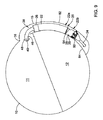
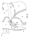
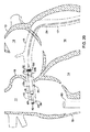
図1は、患者の心臓の右心房、左心房、右心房、及び/又は左心室に電気刺激療法を施すなど、患者の心臓に電気刺激療法を施すための例示的なシステムの概念図である。図1は、心臓10内及び心臓10周囲に植え込まれた例示的なリードレスペーシング装置20を示している。図1の心臓10は、右心房11、左心房12、右心室13、左心室14、冠状静脈洞15、冠状静脈洞口16、大心臓静脈17、及び中隔18を示して描かれている。
FIG. 1 is a conceptual diagram of an exemplary system for applying electrical stimulation therapy to a patient's heart, such as applying electrical stimulation therapy to the right atrium, left atrium, right atrium, and / or left ventricle of the patient's heart. .. FIG. 1 shows an exemplary
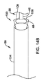
図1の例では、リードレスペーシング装置20は、近位端及び遠位端を有するハウジング22と、ハウジング22の遠位端から遠位方向に延出する遠位延長部24と、を備える。ただし、いくつかの例では、遠位延長部24を備えなくし、さらに/又は1つ以上の他の遠位延長部及び/若しくは近位延長部を備え得る。ハウジング22は、単体部分であり、又は、第1の部分22a(例えば、カン又は本体)、第2の部分22b(例えば、ヘッド部又はモールド部)、及び/若しくは1つ以上の他の部分を有し得る。ハウジング22は、その全長に沿って同じ断面形状を有する必要はないことが想定される。植え込まれるときに、ハウジング22は、患者の心臓10の冠状静脈洞15内に完全又は部分的に留置され得る一方、遠位延長部24は、冠状静脈洞15から延びる血管(例えば、大心臓静脈17、前室間静脈、及び/又はその他の外側方に下降する血管)内に完全又は部分的に留置され得る。
In the example of FIG. 1, the
ハウジング22は、患者の心臓10内の標的部位に植え込むのに適した任意の寸法を有し得る。一例では、ハウジング22は、冠状静脈洞15内に収まるのに十分な断面直径又は断面積を有し得る。冠状静脈洞15のサイズは、ヒトによって約0.12インチ(3mm)〜約0.6インチ(15mm)の間で異なり得る。ハウジング22の直径は、種々の実施形態において、約0.1インチ(2.54mm)〜約0.4インチ(10mm)の範囲であり得る。これらのサイズにより、冠状静脈洞15を通る十分な血液の流れを依然として確保しつつ、様々に異なるサイズの冠状静脈洞内にハウジング22を植え込むことが可能となる。
The
ハウジング22は、その外面に1つ以上の材質を有し得る。ある場合において、ハウジング22の材質は、患者の体内の部位においてハウジング22を安定化し易くする第1の材質と、血液がハウジング22を通り越し易くする第2の材質と、を含み得る。ハウジング22が患者の冠状静脈洞15内に留置されるように構成され得る場合の一例では、興奮性心筋組織に隣接及び/又は接触させることを目的としたハウジング22の第1のサイド(例えば、後述するような凹側及び/若しくはその他のサイド)は、目的の部位においてハウジング22を安定化し易くするための材質表面(例えば、粗い材質)を有し、脂肪組織又は心膜組織に隣接及び/又は接触させることを目的としたハウジング22の第2のサイド(例えば、後述するような凸側若しくはその他のサイド)は、ハウジング22の材質加工された第1のサイドと比較して、冠状静脈洞15内で血液及び/又はその他の液がハウジング22を通り越し易くするための平滑表面を有し得る。材質表面は、サンドブラスト、ビードブラスト、重曹ブラスト、電解研磨、成膜、及び/又は他の1つ以上の材質加工技術によって材質加工され得る。平滑表面は、研磨、保護層の塗布若しくはコーティング、及び/又は他の1つ以上の平滑化技術によって平滑化され得る。
The
いくつかの実施形態では、リードレスペーシング装置20は、さらに、1つ以上の電極を備え得る。一例では、ハウジング22は、第1の電極26及び第2の電極28を支持し得る一方、遠位延長部24は、遠位電極を支持し得る。ある場合において、遠位電極は、複数の電極(例えば、第1の近位リング電極30、第2の近位リング電極32、第3の近位リング電極34、遠位リング電極36、及び/又は他の1つ以上の電極)を含み得る。上記の電極はリング電極であるものとして示され得るが、用途に応じて他の電極タイプを用い得る。
In some embodiments, the
ハウジング22によって支持される電極26、28は、ハウジング22の第1の部分22aと第2の部分22bの両方にそれぞれ配置されるものとして図示しているが、ある場合において、ハウジング22に配置される電極の数及び位置は、用途に応じて様々に異なり得る。例えば、リードレスペーシング装置20が2つのハウジング部分を備える場合に、リードレスペーシング装置20は、第1のハウジング部分22a又は第2のハウジング部分22bの一方のみに配置された電極を有し得る。電極と冠状静脈洞15の壁との間の良好な接触を形成し易くするために、ハウジング22の様々な長手方向長さにおいてハウジング22上に電極を配置することが望ましい場合がある。いくつかの例では、リードレスペーシング装置20は、ハウジング22上に配置された電極を備えなく得る。
The
ハウジング22上の電極26、28の一例の配置では、ハウジング22の第1の部分22aに位置する第1の電極26はアノード電極であり、ハウジング22の第2の部分22bに位置する第2の電極28はカソード電極であり得る。ただし、それらの電極は双極電極であり得るので、本例の配置における第1の電極26をカソード電極に変更し、本例の配置における第2の電極28をアノード電極に変更し得る。対をなす双極電極の極性は、電極の位置に関わりなく切り替えられ得る。
In an example arrangement of the
設けられた場合の、リードレスペーシング装置20の電極は、心臓10に電気刺激を与えるため、及び/又は1つ以上の生理学的信号をセンシングするために、使用され得る。ある場合において、リードレスペーシング装置20は、それらの電極(例えば、電極26〜36又は他の電極)のうちの1つ以上を、限定するものではないが、1つ以上の他のリードレス心臓ペースメーカ及び/又は植込み型除細動器のような、他の1つ以上の装置と通信するために用い得る。いくつかの例では、リードレスペーシング装置20は、伝導通信技術を用いて通信し、電極(例えば、電極26〜36又は他の電極)のうちの1つ以上を通して通信信号を送信及び/又は受信し得る。
When provided, the electrodes of the
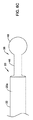
いくつかの例では、ハウジング22は、ハウジング22の近位端から概ね延出する近位部材38(例えば、ドッキングハブ又は他の部材)を含み得る。図1に示す例では、近位部材38は、ハウジング22の第1の部分22aから延出し得る。植え込み時には、近位部材38は、(図1には示していない)位置決め装置に解放可能に結合され得る。結合されると、位置決め装置の動きがハウジング22に伝わり得ることで、医師などの使用者が、ハウジング22を、心臓10内の適切な位置に、例えば冠状静脈洞15内又はその近傍に、操作することが可能となる。
In some examples, the
いくつかの例では、リードレスペーシング装置20は、(図1には示していない)ガイドカテーテルから送達され、ハウジング22を取り囲むガイドカテーテルの部分は、ガイドカテーテルとハウジング22との確実な連結を形成するように、ハウジング22に適合し得る。所定位置になったら、ガイドカテーテルを退避させ、又はスタイレット若しくは他のプッシュ装置でハウジング22をガイドカテーテルから押し出し得る。これらの場合、近位部材38は、さらにテザーアンカ40を含み得る。送達時には、さらなる位置決めのために、使用者がハウジング22をガイドカテーテル内で引き戻すことを可能とするために、テザーアンカ40にテザーを結合し得る。いくつかの例では、テザーはストリングであり、このストリングを、テザーアンカ40に巻き付けることにより、テザーアンカ40に結合させ得る。このテザーをハウジング22から解放するには、使用者は、単に、テザーを切断するか、又はテザーがテザーアンカ40からほどけるまでテザーの一端を引けばよい。
In some examples, the
遠位延長部24を図1に示しているが、いくつかの例では、リードレスペーシング装置20は、遠位延長部24を備えなく得る。リードレスペーシング装置20が、ハウジング22の遠位端(例えば、図1に示すように、ハウジング22の第2の部分22b)から延出する遠位延長部24を備える場合、その備える場合の遠位延長部24は、冠状静脈洞15内に延出して、冠状静脈洞15内に固定され得る。ある場合において、遠位延長部24は、冠状静脈洞15を通って、図1に示すように大心臓静脈17内に、又は冠状静脈洞から延びる他の1つ以上の血管内に、延出し得る。
Although the
遠位延長部24は、近位端24a及び遠位端24bを含み得る。遠位延長部24の遠位端24bは、1つ以上の固定部材42を含み得る。固定部材42は、冠状静脈洞15内又は大心臓静脈17内で、遠位延長部24の遠位端24bを固定する助けとなり得る。固定部材42は、シリコン、生体適合性ポリマ、生体適合性金属、他の生体適合性材料、形状記憶材料(例えば、ニチノール若しくは他の形状記憶材料)、及び/又は生体吸収性材料で構成された1つ以上のアンカ44(例えば、タイン、ヘリカルコイル、タロン、又はその他のアンカ)を含み得る。生体吸収性材料は、当該生体吸収材料でないときは、アンカ44を覆う内皮増殖が起こり得るので、患者からのリードレスペーシング装置20の抜去を容易とするために利用され得る。アンカ44は、遠位延長部24から径方向外向きに延出し、そして、大心臓静脈17の壁に押し当てられ得る。アンカ44と大心臓静脈17の壁との間の力によって、遠位延長部24の遠位端24bを所定位置に保持し得る。
The
固定部材42のアンカ44(例えば、ひいては固定部材42)は、標的部位及び/又は植込み部位における身体血管の弁に対する固定を容易としつつ、身体血管(例えば、静脈、冠状静脈洞など)への容易な挿通を可能とするために、角度付きであり得る。ある場合において、固定部材42のアンカ44は、身体血管内への遠位方向の挿入及び/又は身体血管を通した遠位方向の挿通を容易とするために、近位方向に角度付きであり、さらに、植込み部位において身体血管内の弁に係合して、遠位延長部24を固定するために(例えば、近位方向の移動を阻止又は制限するために)、近位方向に遠位延長部24の長手軸から径方向外向きに延出し得る。
The
図面では、遠位延長部24に1つの固定部材42を示しているが、遠位延長部24は、図面に示す固定部材42から軸方向に離間した1つ以上の追加の固定部材を支持し得る。他の例では、遠位延長部24は、固定部材42を含まなくなり得る。
Although the drawings show one fixing
ある場合において、固定部材42は、1つ以上の電極又はワイヤループを含み、他の1つ以上の装置と通信し、かつ/又は他の1つ以上の装置から電気エネルギーを受信するためのアンテナとして機能し得る。例えば、リードレスペーシング装置20は、誘導通信技術及び/又は伝導通信技術を用いて、固定部材42の電極及び/又はワイヤループを介して、エネルギー伝送を受信し、かつ/又は通信し得る。
In some cases, the fixing
上述のように、遠位延長部24は、1つ以上の電極(例えば、電極30〜36)を含み得る。これらの例のいくつかでは、電極30〜36は、遠位延長部24の遠位端24bの近傍に、ハウジング22から離間して配置され得るが、ただし、他の例では、遠位延長部24上の1つ以上の電極は、遠位延長部24の、ある長さ(例えば、全長)にわたり得る。
As mentioned above, the
ある場合において、遠位延長部24上の電極は、心臓10に電気刺激を与えるために使用され得る。例えば、リードレスペーシング装置20は、電極のうちの1つ以上のセット(例えば、電極30〜36又は他の電極からの、ある電極セット)を通して、心臓10の左心室14に電気刺激を与え得る。ある場合において、リードレスペーシング装置20は、電極30〜36のうちの2つ以上を用いて、同時に、又は(例えば、マルチ電極ペーシングにより)遅延を伴って、心臓10の左心室14に電気刺激を与え得る。いくつかの追加的又は代替的な場合には、リードレスペーシング装置20は、他の1つ以上の装置と通信するために、電極30〜36のうちの1つ以上を使用し得る(例えば、電極30〜36はアンテナとして機能し得る)。例えば、リードレスペーシング装置20は、誘導通信技術又は伝導通信技術を用いて、電極30〜36のうちの1つ以上を介して、エネルギー伝送を受信し、かつ/又は通信し得る。
In some cases, the electrodes on the
リードレスペーシング装置20上の電極26〜36及び/又は他の電極は、電気信号をセンシングすること、電気刺激信号を付与すること、又は電気信号をセンシングするとともに電気刺激信号を付与すること、が可能であり得る。信号処理、通信、及び/又は治療パルスの発生は、適切な処理モジュールが配置され得るリードレスペーシング装置の任意の部分で行われ得る。一例では、リードレスペーシング装置20の電極(例えば、電極26〜36及び/又は他の電極)に関する信号処理、通信、及び治療パルスの発生は、ハウジング22内又はハウジング22に支持されたモジュールにおいて行われ得るが、ただし、これは必須ではない。
Electrodes 26-36 and / or other electrodes on the
リードレスペーシング装置20の電極26〜36及び/又は他の電極は、心臓興奮イベントの近フィールドセンシング及び/又は遠フィールドセンシングを実行するように構成され得る。心臓興奮イベントの「近フィールド」センシングとは、当該電極が位置する局所腔(例えば、電極がセンシングしているのと同じ心腔)で発生する心臓興奮イベントをセンシングすることを指す。心臓興奮イベントの「遠フィールド」センシングとは、当該電極が位置する局所腔以外の心腔で発生する心臓興奮イベントをセンシングすることを指す。例えば、リードレスペーシング装置20の電極が冠状静脈洞15内に留置されて、右心房11の壁を形成する冠状静脈洞15の壁に隣接した電極を有する場合に、その電極は、右心房興奮イベントを近フィールドセンシングし、左心房興奮イベント、左心室興奮イベント、及び右心室興奮イベントを遠フィールドセンシングする。
Electrodes 26-36 and / or other electrodes of the
冠状静脈洞15内及び冠状静脈洞15から延びる血管(例えば、大心臓静脈17)内にリードレスペーシング装置20が植え込まれる図1の例では、第1の電極26(例えば、ハウジング22上で近位側に位置する電極)は、冠状静脈洞15内で右心房11に隣接して留置され、第2の電極28(例えば、ハウジング22上で遠位側に位置する電極)は、冠状静脈洞15内で左心房12に隣接して留置され、遠位延長部24によって支持された電極30〜36は、大心臓静脈17内で左心室14に隣接して留置され得る。このような植え込み構成では、第1の電極26は、右心房11の心臓組織における心房興奮イベント(P波)の近フィールド信号をセンシングするとともに、右心房11の心臓組織にペーシングパルスを供給し、第2の電極は、左心房12の心臓組織における心房興奮イベント(P波)の近フィールド信号をセンシングするとともに、左心房12の心臓組織にペーシングパルスを供給し、遠位延長部24によって支持された電極30〜36は、心房で発生して房室結節及びヒス・プルキンエ系を介して伝導された、左心室14の心臓組織における心室興奮イベント(R波)の近フィールド信号をセンシングするとともに、左心室14の心臓組織にペーシングパルスを供給し得る。
In the example of FIG. 1 in which the
追加的又は代替的に、リードレスペーシング装置20の電極26〜36又は他の電極は、遠フィールドセンシングによって信号をセンシングし得る。例えば、ハウジング22によって支持され得る電極26、28は、心室興奮活動(R波)を遠フィールドセンシングし、遠位延長部24によって支持された電極30〜36は、心房興奮活動(P波)を遠フィールドセンシングし得る。ただし、このようなセンシング信号は、減衰及び遅延することがあり、かつ/又は振幅及び持続時間が、心房興奮活動及び心室興奮活動の信頼できるセンシングのためには不十分であり得るとともに、遠フィールドセンシングによりセンシングされる信号を考慮する場合には、近フィールドセンシングによりセンシングされる信号を考慮する必要があり得る。
Additional or alternative, electrodes 26-36 or other electrodes of the
ある場合において、リードレスペーシング装置20は、要求に応じて、右心房11、左心房12、右心室13、及び/又は左心室14に電気刺激を付与し得る単独装置として(例えば、1つ以上の他のリードレスペーシング装置又は1つ以上の植込み型除細動器を伴うことなく)植え込まれ得る。例えば、リードレスペーシング装置20は、心房細動又は心房粗動を治療するための治療プログラムに従って、電気刺激を与えるように構成され得る。一方、他の場合には、リードレスペーシング装置20は、心臓10内及び/又は心臓10周囲の1箇所以上の様々な部位に植え込まれる1つ以上の他のリードレスペーシング装置及び/又は1つ以上の他の植込み型除細動器を伴って、植え込まれ得る。
In some cases, the
リードレスペーシング装置20を使用する一例では、リードレスペーシング装置20は、心臓再同期療法(CRT)を心臓10に施すためのシングルデバイスシステム又はマルチデバイスシステムの一部であり得る。これらの例では、リードレスペーシング装置20は、右心房11及び左心房12の一方又は両方において、心臓電気信号をセンシングし得る。リードレスペーシング装置20が、右心房11内及び/又は左心房12内を伝播する心臓電気信号をセンシングしたら、リードレスペーシング装置20は、遅延期間(例えば、房室(AV:AtrioVentricular)遅延)の後に、ペーシングパルスを左心室14に供給し得る。その遅延期間の長さは、伝播する心臓電気信号が右心室13に到達して右心室13を収縮させるときに、リードレスペーシング装置20がペーシングパルスを左心室14に供給し得るように、決定又は選択され得る。このようにして、リードレスペーシング装置20は、右心室13と左心室14を同期収縮させるように作用し得る。いくつかの追加的な例では、リードレスペーシング装置20は、感知された心拍数に基づいて遅延期間を調整し得る。例えば、リードレスペーシング装置20が心拍数の増加をセンシングすると、リードレスペーシング装置20は、遅延期間の長さを短縮し得る。逆に、リードレスペーシング装置20が心拍数の低下をセンシングすると、リードレスペーシング装置20は、遅延期間を延長し得る。
In one example of using the
上述のように、リードレスペーシング装置20は、冠状静脈洞15を介して右心房11及び/又は左心房12にペーシングパルスを供給し得る。これらの実施形態では、リードレスペーシング装置20は、リードレスペーシング装置20が右心房11及び/又は左心房12にペーシングパルスを供給した時点で、又はその直後に、遅延期間の計測を開始し得る。前述の実施形態と同様に、これにより、右心室13と左心室14を同期収縮させ得る。リードレスペーシング装置20が、右心室13内に追加のリードレスペーシング装置を備えたシステムの一部である場合に、リードレスペーシング装置20が右心房11及び/又は左心房12にペーシングパルスを供給した後に、リードレスペーシング装置20は、追加のリードレスペーシング装置にトリガを伝達し得る。そのトリガを受信した後に、追加のリードレスペーシング装置は、その独自の遅延期間の後に、ペーシングパルスを右心室13に供給し得る。これらの例の少なくともいくつかでは、追加のリードレスペーシング装置とリードレスペーシング装置20の両方が、右心室13と左心室14に同期的にペーシングパルスを供給するように、追加のリードレスペーシング装置の遅延期間とリードレスペーシング装置20の遅延期間を整合させ得る。一方、他の実施形態では、例えば、右心室13と左心室14を通した伝導が異なる場合に、右心室13と左心室14を同期的に収縮させるために、追加のリードレスペーシング装置の遅延期間とリードレスペーシング装置20の遅延期間は異なり得る。
As described above, the
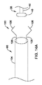
図2は、例示的なリードレスペーシング装置20の概略図である。例示的なリードレスペーシング装置20は、第1のハウジング部分22a及び第2のハウジング部分22bを有するハウジング22を、ある場合においてハウジング22から遠位方向に延出する遠位延長部24と共に、含み得る。ハウジング22は、単体ハウジングであり、又はリードレスペーシング装置20の1つ以上のコンポーネントを収容した2つ以上のハウジング部分(例えば、第1の部分22a、第2の部分22b、及び/又は他の1つ以上のハウジング部分)を含み得る。ハウジング22は、主に、生体適合性金属及び/又は生体適合性ポリマのような生体適合性材料を含み、患者の体内に植え込まれているときに、リードレスペーシング装置20のコンポーネントを、患者の体液及び生体組織からハーメチックシールし得る。リードレスペーシング装置20は、さらに、電極26、28及び/又は他の電極のような1つ以上の電極を有し、それらは、図示の例では、ハウジング22によって支持される(例えば、ハウジング22上にある、ハウジング22から延出している、さらに/又は他の何らかの方法でハウジング22に支持される)。ある場合において、ハウジング22は、異なる数の電極を有し得るか、又は電極を全く有し得ないことが想定される。
FIG. 2 is a schematic view of an exemplary
ハウジング22が2つ以上の部分を含む場合の例では、第1の部分22aは本体であり、第2の部分22bはヘッダであり得る。第1の部分22a(例えば、本体)は、生体適合性金属材料、又はリードレスペーシング装置20の電子部品を封入するのに適した他の材料、で構成され得る。第2の部分22b(例えば、ヘッダ)は、生体適合性ポリマ又はその他の材料で構成され得る。いくつかの例では、第2の部分は、ポリマで構成され、そしてオーバモールドプロセスで、ハウジング22の第1の部分22aの遠位端の上にオーバモールドされ得る。第2の部分22bをモールド技術で形成するときに、遠位延長部24は、遠位延長部24の近位端の上に第2の部分22bをオーバモールドすることにより、ハウジング22に連結され得る。
In the example where the
いくつかの例では、上述のように、ハウジング22は、ハウジング22の第1の部分22aの近位端から延出する近位部材38(例えば、ドッキングハブ)を含み得る。ある場合において、近位部材38は、ハウジング22から突出するとともに第1の外径を有する延長部46を含み、延長部46の近位端は、第2の直径を有する付属体48に連結されるか、又は付属体48を形成し得る。図2に示す例では、付属体48の第2の外径は、延長部46の第1の外径よりも大きく得るが、他の適切な構成も想定される。
In some examples, as described above, the
植え込み時には、位置決め装置を、近位部材38に解放可能に結合し得る。結合されると、位置決め装置の動きがハウジング22に伝わり得ることで、使用者が、リードレスペーシング装置20を植え込み時に位置決めすることが可能となる。ある場合において、近位部材38は、延長部46及び付属体48に対して代替的又は追加的に、インタロック機構の半分を含み、位置決め装置は、近位部材38のインタロック機構に解放可能に結合し得るインタロック機構の残り半分を有し得る。
At the time of implantation, the positioning device may be releasably coupled to the
いくつかの例では、ハウジング22は、固定部材50を含み得る。固定部材は、リードレスペーシング装置20が心臓10の冠状静脈洞15内に植え込まれるときに、リードレスペーシング装置20を冠状静脈洞15内に維持するように構成され得る。固定部材50は、シリコン、生体適合性ポリマ、生体適合性金属、他の生体適合性材料、形状記憶材料(例えば、ニチノール若しくは他の形状記憶材料)、及び/又は生体吸収性材料で構成された1つ以上のアンカ52(例えば、タイン、ヘリカルコイル、タロン、又はその他のアンカ)を含み得る。生体吸収性材料は、当該材料でなければアンカ52を覆う増殖物が生じ得るリードレスペーシング装置20の患者からの抜去を容易とするために利用され得る。アンカ52は、遠位延長部24から径方向外向きに延出し、かつ、冠状静脈洞15の壁に押し当てられ得る。アンカ52と冠状静脈洞15の壁との間の力によって、ハウジング22を冠状静脈洞15内の所定位置に保持し得る。
In some examples, the
固定部材50のアンカ52(例えば、ひいては固定部材50)は、標的部位及び/又は植込み部位における身体血管の弁に対する固定を容易としつつ、身体血管(例えば、静脈、冠状静脈洞など)への容易な挿通を可能とするために、角度付きであり得る。ある場合において、固定部材50のアンカ52は、身体血管内への遠位方向の挿入及び/又は身体血管を通した遠位方向の挿通を容易とするために、近位方向に角度付きであり、さらに、植込み部位において身体血管内の弁に係合して、ハウジング22を固定するために(例えば、近位方向の移動を阻止又は制限するために)、近位方向にハウジング22の長手軸から径方向外向きに延出し得る。
The
少なくともいくつかの例では、固定部材50によって、さらに、ハウジング22は、(例えば、アンカ52が、ハウジング22の周りで等間隔に周方向に離間している場合に)例えば冠状静脈洞15の内腔の中央に浮遊するか、又は(例えば、アンカ52が、ハウジング22の周りで不等間隔に周方向に離間している場合に)心臓10の心腔壁を形成する冠状静脈洞15の壁に押し当てられるなど、冠状静脈洞15の内腔に対して所望の配置に維持され得る。
In at least some examples, the anchoring
図面では、ハウジング22に1つの固定部材50を示しているが、ハウジング22は、図面に示す固定部材50から軸方向に離間した1つ以上の追加の固定部材を支持し得る。他の例では、ハウジング22は、固定部材50を含まなくなり得る。
Although the drawing shows one fixing
ある場合において、固定部材50(及び/又は固定部材42)は、1つ以上の電極又はワイヤループを含み、他の1つ以上の装置と通信し、かつ/又は他の1つ以上の装置から電気エネルギーを受信するためのアンテナとして機能し得る。例えば、リードレスペーシング装置20は、誘導通信技術及び/又は伝導通信技術を用いて、固定部材50の電極及び/又はワイヤループを介して、エネルギー伝送を受信し、かつ/又は通信し得る。
In some cases, the fixing member 50 (and / or the fixing member 42) comprises one or more electrodes or wire loops, communicates with one or more other devices, and / or from one or more other devices. It can function as an antenna for receiving electrical energy. For example, the
ハウジング22の第2の部分22bは、1つ以上の凹部53を含み得る。一例では、ハウジング22の第2の部分22bは、固定部材50の各アンカ52と揃った位置に凹部53を含み、これにより、リードレスペーシング装置を標的部位(例えば、冠状静脈洞15)に送達する際に、アンカ52が、(例えば、ガイドカテーテル、イントロデューサシースなどから)付与された力に応じて関節動作し得るとともに、対応する凹部53内に少なくとも部分的に配置され得る。
The
少なくともいくつかの場合に、ハウジング22は、ハウジング22の第1端から第2端まで延びるハウジング22の側部を通り抜けて延びるガイドワイヤポート54を有し得る。ある場合において、ガイドワイヤポート54は、ハウジング22の第2の部分22b又はその近傍に配置され得るとともに、ガイドワイヤを受容するように構成され得る。リードレスペーシング装置20が遠位延長部24を含む場合に、遠位延長部24は、遠位延長部24の遠位端24bの遠位先端から延びる対応するガイドワイヤポートを有し得る。このような例では、ガイドワイヤは、大心臓静脈17(又は冠状静脈洞15につながっている他の血管)に沿って下降するように留置され得る。リードレスペーシング装置20は、ガイドワイヤの近位端を遠位延長部24に通すようにして遠位延長部24をガイドワイヤの近位端上に装着してから、ガイドワイヤ上に沿ってリードレスペーシング装置20を所定位置まで進めることにより、ガイドワイヤ上を辿り得る。リードレスペーシング装置20が遠位延長部24を含まない実施形態では、ハウジング22は、第2のガイドワイヤポートを含み得る。
In at least some cases, the
遠位延長部24は、特にハウジング22と比較して、細長い可撓性部材であり得る。例えば、遠位延長部24は、ハウジング22の長さの2倍〜10倍の間であり得る。さらに、上述のように、遠位延長部24は、1つ以上の固定部材42を有し得る。ある場合において、固定部材42は、遠位延長部24の遠位端24b又はその近傍に配置され得る。ある場合において、遠位延長部24は、1つ以上の電極(例えば、電極30〜36)を含み得る。
The
電極30〜36及び/又は他の電極は、遠位延長部24の遠位端24bの近傍に配置でき、又は図2に示すように、遠位延長部24の長さに沿って分散し(例えば、長手方向に互いに離間し)得る。遠位延長部24上の電極の他の配置及び/又は構成が想定され、それらを用い得る。(例えば、電極30〜36を用いた)電極の一例の配置では、電極のそれぞれはリング電極であり、そして、電極36(例えば、遠位リング電極)は、遠位延長部24上において遠位延長部24の遠位先端の近傍に配置でき、電極34(例えば、第3の近位リング電極)は、電極36から近位方向に40ミリメートル離間でき、電極32(例えば、第2の近位リング電極)は、電極34から近位方向に10ミリメートル離間でき、電極30(例えば、第1の近位リング電極)は、電極32から近位方向に10ミリメートル離間させ得る。電極30〜36のこのような構成は、リードレスペーシング装置20による患者の心臓10の左心房12のセンシング及び/又はペーシングを可能とするために、遠位延長部24が大心臓静脈17又は他の血管に挿入されたときに、左心房12に合致し得る。ある場合において、遠位延長部24は、ヘリカルコイル又は1巻以上のループのような形状をなすように付勢され得る。
Electrodes 30-36 and / or other electrodes can be placed near the
図3は、リードレスペーシング装置20のハウジング22内に格納され得る1つ以上の電子モジュールの概略ブロック図である。いくつかの例では、リードレスペーシング装置20は、エネルギー貯蔵モジュール56(例えば、電源電圧を供給/付与するための電源)、処理モジュール58、通信モジュール60、パルス発生器モジュール62、電気的センシングモジュール64、及び/又は機械的センシングモジュール66、を備え得る。図3は、さらに導体68〜72も示しており、これらは、モジュール56、58、60、62、64のうちの1つ以上から延出し、かつ/又は1つ以上の電極(例えば、電極26〜36又は他の電極)まで延び得る。3つの導体のみを図3に示しているが、別の導体が、ハウジング22内のモジュールからリードレスペーシング装置20の電極のそれぞれまで延び得る。従って、少なくともいくつかの例では、リードレスペーシング装置20の電子要素及びエネルギー貯蔵モジュールはすべて、ハウジング22内に格納され得る一方、1つ以上の導体のみが電極まで及んでいる。一例では、導体68は、ハウジング22によって支持された第1の電極26まで延び、導体70は、ハウジング22によって支持された第2の電極28まで延び、導体72は、遠位延長部上の電極30〜36まで及ぶ導体を表し得るものであって、この場合、単一の導体が各電極30〜36まで及び得るとともに、遠位リング電極36まで及ぶ導体は、その導体が遠位リング電極36に到達するまでの間、遠位延長部24のルーメン76に沿って、かつ/又はその周りに、巻回され得る。追加的又は代替的に、必要に応じて、他の導体がルーメン76の周りに巻回され得る。電極まで延びる各導体は、その他の導体から電気的に絶縁されて、ある場合において、各導体は、それに専用のルーメンを通して、関連した電極まで延び得るが、ただし、これは必須ではない。
FIG. 3 is a schematic block diagram of one or more electronic modules that can be housed in the
図3に示す例では、通信モジュール60は、電極26〜36に電気的に接続されて、センサ、プログラマ、他の医療装置などのような他の装置と通信するために、患者の組織に対して電気通信パルスのような通信信号を送信するように構成され得る。本明細書で使用する場合の電気通信パルスは、単独で、又は他の1つ以上の変調信号と連携して他の装置に情報を伝える、任意の変調信号であり得る。いくつかの実施形態では、電気通信パルスは、結果的に心臓の捕捉には至らないものの依然として情報は伝達する、閾値以下の信号に制限され得る。電気通信パルスは、患者の生体の外部又は内部のいずれかに位置する他の装置に対して送出され得る。通信モジュール60は、さらに、患者の生体の外部又は内部に位置し得る他の装置によって送出された電気通信パルスをセンシングするように構成され得る。
In the example shown in FIG. 3, the
通信モジュール60は、1つ以上の所望の機能の実現を助けるために通信し得る。いくつかの例示的な機能として、感知されたデータの伝達、伝達されたデータを不整脈のようなイベントの発生の確認に使用すること、電気刺激療法施与のコーディネート、及び/又はその他の機能が含まれる。ある場合において、リードレスペーシング装置20は、未加工情報、処理済み情報、メッセージ及び/若しくはコマンド、並びに/又はその他のデータを伝達するために、電気通信パルスを用いることがある。未加工情報は、感知された電気信号(例えば、感知された心電図(ECG:ElectroCardioGraph))、接続されたセンサから収集された信号などのような情報を含み得る。いくつかの実施形態では、処理済み情報は、1つ以上の信号処理技術を用いてフィルタリングされた信号を含み得る。処理済み情報は、さらに、特定された心拍数、特定された心拍のタイミング、その他の特定されたイベントのタイミング、閾値交差の判定、監視期間の終了、活動レベルパラメータ、血液酸素パラメータ、血圧パラメータ、心音パラメータなどのような、リードレスペーシング装置20及び/又は他の装置によって特定されたパラメータ及び/又はイベントを含み得る。メッセージ及び/若しくはコマンドは、他の装置にアクションの実行を指示する命令など、送信側装置の緊急アクションの通知、受信側装置からの読み取りを求める要求、受信側装置へのデータの書き込みを求める要求、情報メッセージ、及び/又はその他のメッセージコマンド、を含み得る。
The
パルス発生器モジュール62は、1つ以上の電気刺激療法を実施するために、電気刺激パルスを発生し、その電気刺激パルスを、電極26〜36のうちの1つ以上を介して患者の組織に供給するように構成され得る。本明細書で使用される場合の電気刺激パルスは、いずれかのタイプの疾患又は異常の治療を目的として患者の組織に付与され得るあらゆる電気信号を包含するものである。例えば、心臓病の治療に使用される場合、パルス発生器モジュール62は、患者の心臓を捕捉するための、すなわち付与された電気刺激パルスに応答して心臓を収縮させるための、電気刺激ペーシングパルスを発生し得る。他の実施形態では、電気刺激パルスは、除細動のためのショックを心臓に与えるための電気的除細動/カーディオバージョンパルスであり得る。さらなる他の実施形態では、電気刺激パルスは、抗頻拍ペーシング(ATP:anti−tachycardia pacing)パルスであり得る。これらは、ほんの一例である。他の疾患の治療に使用される場合には、パルス発生器モジュール62は、神経刺激療法などに適した電気刺激パルスを発生することがある。パルス発生器モジュール62は、適切な電気刺激パルスの発生及び送出を支援するために、1つ以上のキャパシタ素子及び/又は他の蓄電素子を含み得る。図示の実施形態では、パルス発生器モジュール62は、電気刺激パルスを発生するために、エネルギー貯蔵モジュール56に蓄積されたエネルギーを使用し得る。
The
少なくともいくつかの実施形態では、通信モジュール60(あるいはリードレスペーシング装置20)は、さらに、通信モジュール60がどの電極26〜36に電気通信パルスを送出するかを選択するために、電極26〜36の1つ以上を通信モジュール60に選択的に接続するためのスイッチング回路を含み得る。通信モジュール60は、伝導信号、高周波(RF:Radio Frequency)信号、光信号、音響信号、誘導接続、及び/又は他の適切な通信方法によって、他の装置と通信し得ることが想定される。
In at least some embodiments, the communication module 60 (or leadless pacing device 20) further comprises electrodes 26-36 to select which electrodes 26-36 the
パルス発生器モジュール62は、電気刺激パルスのパルス幅及び/又は振幅を調整するなどして、電気刺激パルスを修正する機能を有し得る。これは、心臓ペーシング時に、ある場合においてバッテリ使用量の削減を伴って、特定の患者の心臓を捕捉するのに合わせて電気刺激パルスを調整する助けとなり得る。神経刺激療法の場合に、パルス幅及び/又は振幅を調整することは、特定の応用に合わせて治療法を調整する助けとなることがあり、さらに/又は治療法を特定の患者に対してより効果的にする助けとなることがある。
The
電気的センシングモジュール64は、1つ以上の電極26〜36に電気的に接続され、電気的センシングモジュール64は、電極26〜36を介して伝導される心臓電気信号を受信するように構成され得る。いくつかの実施形態では、心臓電気信号は、リードレスペーシング装置20が冠状静脈洞15内及び/又はそこから延びる血管内に植え込まれたときに、リードレスペーシング装置20の電極が位置する心腔若しくはその周囲に電極が位置する心腔からの、局所情報(例えば、近フィールド情報)を表し得る。例えば、リードレスペーシング装置20の電極(群)が心臓の心室又は心室の周囲に留置された場合に、電極(群)によりセンシングされる心臓電気信号は、近フィールド信号であり得るとともに、心室心臓電気信号を表し得る。
The
機械的センシングモジュール66は、加速度計、血圧センサ、心音センサ、血液酸素センサ、並びに/又は心臓及び/若しくは患者の1つ以上の生理学的パラメータを測定する他のセンサのような、各種センサを含み得るか、又は各種センサに電気的に接続され得る。設けられた場合の、機械的センシングモジュール66は、それらのセンサからの、様々な生理学的パラメータを示す信号を収集し得る。電気的センシングモジュール64と機械的センシングモジュール66は両方とも、処理モジュール58に接続され得るとともに、感知された心臓電気信号及び/又は生理学的信号を表す信号を処理モジュール58に供給し得る。電気的センシングモジュール64と機械的センシングモジュール66は、図3に関連して、別々のセンシングモジュールとして記載されるが、いくつかの実施形態では、単一のモジュールに併合され得る。
The
処理モジュール58は、リードレスペーシング装置20の動作を制御するように構成され得る。例えば、処理モジュール58は、電気的センシングモジュール64からの近フィールド心臓電気信号及び/若しくは遠フィールド心臓電気信号、並びに/又は機械的センシングモジュール66からの生理学的信号、を受信するように構成され得る。処理モジュール58は、受信した近フィールド信号及び/若しくは遠フィールド信号に基づいて、(例えば、心房イベント並びに/又は心室イベントが発生する場合に)例えば、不整脈の発生及びタイプを特定し得る。一例では、処理モジュール58は、P波、R波、T波、及び/又は関心のある他の心臓イベントを、それぞれの波/イベントの相対タイミングと共に、識別し得る。
The
図1に示すように植え込まれたリードレスペーシング装置20の一例では、処理モジュール58は、ハウジング22によって支持された電極26、28の1つ以上を用いて感知された近フィールド信号に基づいて心房イベントが発生したか否かを判定し得る。処理モジュール58は、遠位延長部24によって支持された電極30〜36の1つ以上を用いて感知された近フィールド信号に基づいて、心室イベントが発生したか否かを判定し得る。さらに/又は、処理モジュール58は、双極構成若しくは他の構成において空間的に対向した電極(例えば、ハウジング22上の電極26、28の1つ以上、及び遠位延長部24上の電極30〜36の1つ以上)を用いて感知された近フィールド信号に基づいて心房イベント若しくは心室イベントが発生したか否かを判定し得る。追加的又は代替的に、処理モジュール58は、電極26、28の1つ以上を用いて感知された遠フィールド信号に基づいて、心室イベントが発生したか否かを判定し得る。処理モジュール58は、電極30〜36の1つ以上を用いて感知された遠フィールド信号に基づいて、心房イベントが発生したか否かを判定し得る。処理モジュール58は、さらに/又は双極構成若しくは他の構成において空間的に対向した電極(例えば、ハウジング22上の電極26、28の1つ以上、及び遠位延長部24上の電極30〜36の1つ以上)を用いて感知された遠フィールド信号に基づいて、心房イベント若しくは心室イベントが発生したか否かを判定し得る。さらに、どの電極(群)で信号をセンシングしたのかに応じて、処理モジュール58は、センシング信号のタイプ(例えば、遠フィールド又は近フィールド)、その信号をセンシングする電極の心臓10内における部位、及び1つ以上の他のセンシング信号に対するセンシング信号のタイミング、のうちの1つ以上に基づいて、確認された心臓興奮イベントが発生した心腔を特定し得る。例えば、処理モジュールは、右心房11における第1の電極26から感知された近フィールド信号に基づいて確認された心臓イベントは、その心臓イベントが右心房心臓興奮イベントであることを意味することを示し得る。
In an example of an implanted
処理モジュール58は、さらに、通信モジュール60からの情報を受信し得る。いくつかの実施形態では、処理モジュール58は、そのような受信情報を追加的に用いて、不整脈の発生及びタイプを特定し得る。一方、他の実施形態では、例えば、その受信情報が電気的センシングモジュール64及び/若しくは機械的センシングモジュール66から受信した信号よりも正確である場合に、又は電気的センシングモジュール64及び/若しくは機械的センシングモジュール66が無効にされるかリードレスペーシング装置20から省かれている場合に、リードレスペーシング装置20は、その受信情報を、電気的センシングモジュール64及び/若しくは機械的センシングモジュール66から受信した信号の代わりに用いることがある。
The
処理モジュール58は、確認された不整脈(例えば、確認された心房心臓イベント及び/又は心室心臓イベント)に基づいて、確認された不整脈を治療するための1つ以上の電気刺激療法に従って電気刺激パルスを発生するために、パルス発生器モジュール62を制御し得る。例えば、処理モジュール58は、1つ以上の電気刺激療法を実施するための様々に異なるパラメータ及び様々に異なるシーケンスでペーシングパルスを発生するために、パルス発生器モジュール62を制御し得る。例えば、徐脈ペーシング治療を施すためのパルス発生器モジュール62の制御では、処理モジュール58は、患者の心拍が所定閾値を下回ることを防ぐ助けとするために、患者の心臓を一定間隔で捕捉するようにデザインされたペーシングパルスを送出するように、パルス発生器モジュール62を制御し得る。ある場合において、患者の活動レベルの増加に伴って、ペーシングレートを増加させ得る(例えば、心拍適合ペーシング)。ATP治療の場合、内因性心臓電気信号に応答するのではなく、付与されたペーシングパルスに応答して心臓を拍動させるために、処理モジュール58は、患者の内因性心拍数よりも高いレートでペーシングパルスを送出するように、パルス発生器モジュール62を制御し得る。心臓がペーシングパルスに追従するようになったら、処理モジュール58は、送出されるペーシングパルスのレートをより安全なレベルまで下げるように、パルス発生器モジュール62を制御し得る。CRTでは、処理モジュール58は、心臓をより効率的に収縮させるために、他の装置と協調してペーシングパルスを送出するように、パルス発生器モジュール62を制御し得る。パルス発生器モジュール62が、電気的除細動/カーディオバージョン治療のための電気的除細動パルス及び/又はカーディオバージョンパルスを発生することが可能な場合に、処理モジュール58は、そのような電気的除細動パルス及び/又はカーディオバージョンパルスを発生させるように、パルス発生器モジュール62を制御し得る。ある場合において、処理モジュール58は、上記の例とは異なる電気刺激療法を施すための電気刺激パルスを発生するように、パルス発生器モジュール62を制御することがある。
The
様々に異なるタイプの電気刺激パルスを様々に異なるシーケンスで発生するためにパルス発生器モジュール62を制御することとは別に、いくつかの実施形態では、処理モジュール58は、さらに、それらの様々な電気刺激パルスを、様々に異なるパルスパラメータで発生するためにも、パルス発生器モジュール62を制御することがある。例えば、それぞれの電気刺激パルスは、パルス幅及びパルス振幅を有し得るとともに、1つ以上の電極から誘導され得る。処理モジュール58は、それらの様々な電気刺激パルスを、特定のパルス幅、特定のパルス振幅、及び特定の電極(例えば、リードレスペーシング装置20の電極26〜36の1つ以上又は他の電極)で発生するように、パルス発生器モジュール62を制御し得る。一例として、処理モジュール58は、電気刺激パルスが効果的に心臓を捕捉していない場合に、電気刺激パルスのパルス幅及び/又はパルス振幅を、パルス発生器モジュール62に調整させることがある。様々な電気刺激パルスの特定のパラメータのこのような制御は、リードレスペーシング装置20が電気刺激療法のより効果的な施与を提供する助けとなり得る。
Apart from controlling the
いくつかの実施形態では、処理モジュール58は、さらに、他の装置に情報を送信するために、通信モジュール60を制御し得る。例えば、処理モジュール58は、装置群からなるシステムの他の装置と通信するための、1つ以上の電気通信パルスを発生するために、通信モジュール60を制御し得る。例えば、処理モジュール58は、電気通信パルスを特定のシーケンスで発生するために、通信モジュール60を制御する。その場合、それらの特定のシーケンスは、様々に異なる情報を伝達する。通信モジュール60は、さらに、処理モジュール58による可能性のあるアクションのための通信信号を受信し得る。
In some embodiments, the
さらなる例では、処理モジュール58は、スイッチング回路を制御し、これにより、通信モジュール60及びパルス発生器モジュール62は、電気通信パルス及び/又は電気刺激パルスを患者の組織に対して送出する。上述のように、通信モジュール60とパルス発生器モジュール62の両方は、1つ以上の電極26〜36を通信モジュール60及び/又はパルス発生器モジュール62に接続するための回路を含み、これにより、それらのモジュールは、ハウジング22によって支持された電極26、28の1つ以上及び/又は遠位延長部24によって支持された電極30、32、34、36の1つ以上を介して、電気通信パルス及び電気刺激パルスを患者の組織に対して送出し得る。通信モジュール60及び/又はパルス発生器モジュール62が電気通信パルス及び電気刺激パルスを送出するときに介する1つ以上の電極の特定の組み合わせは、通信パルスの受信及び/又は電気刺激パルスの有効性に影響を及ぼし得る。通信モジュール60とパルス発生器モジュール62は、それぞれがスイッチング回路を含み得るものとして記載したが、いくつかの実施形態では、リードレスペーシング装置20は、リードレスペーシング装置20の通信モジュール60、パルス発生器モジュール62、及び電極26〜36に接続された、単一のスイッチングモジュールを備え得る。このような場合、ハウジング22によって支持された電極26、28の1つ以上及び/又は遠位延長部24によって支持された電極30、32、34、36の1つ以上を介して、電気通信パルス及び電気刺激パルスを患者の組織に対して発生するために、処理モジュール58は、適宜、リードレスペーシング装置20のモジュール60/62と電極26〜36とを接続するように、スイッチングモジュールを制御し得る。
In a further example, the
いくつかの例では、処理モジュール58は、超大規模集積(VLSI)チップ又は特定用途向け集積回路(ASIC)のような予めプログラムされたチップを含み得る。そのような実施形態では、チップは、リードレスペーシング装置20の動作を制御するための制御ロジックで予めプログラムされ得る。予めプログラムされたチップを使用することにより、処理モジュール58は、基本機能を維持することが可能でありつつ、他のプログラマブル回路よりも少ない電力を使用し得ることで、リードレスペーシング装置20のバッテリ寿命が長くなる可能性がある。他の例では、処理モジュール58は、プログラマブルマイクロプロセッサなどを含み得る。このようなプログラマブルマイクロプロセッサにより、製造後に使用者によるリードレスペーシング装置20の制御ロジックの調整を可能とすることで、予めプログラムされたチップを使用する場合よりも、リードレスペーシング装置20の高い柔軟性を確保する。
In some examples, the
処理モジュール58は、さらなる例では、メモリ回路を含み、処理モジュール58は、そのメモリ回路に情報を保存し得るとともに、メモリ回路から情報を読み取り得る。他の例では、リードレスペーシング装置20は、処理モジュール58と通信する別個のメモリ回路(図示せず)を含み、これにより、処理モジュール58は、その別個のメモリ回路から情報を読み取り得るとともに、その別個のメモリ回路に情報を書き込み得る。メモリ回路は、処理モジュール58の一部であるか処理モジュール58とは別個であるかに関わりなく、揮発性メモリ、不揮発性メモリ、又は揮発性メモリと不揮発性メモリの組み合わせであり得る。
In a further example, the
エネルギー貯蔵モジュール56は、リードレスペーシング装置20に対して、その動作のため電源を提供し得る。いくつかの実施形態では、エネルギー貯蔵モジュール56は、非充電式リチウム系バッテリであり得る。他の実施形態では、非充電式バッテリは、他の適切な材料で構成され得る。いくつかの実施形態では、エネルギー貯蔵モジュール56は、充電式バッテリを含み得る。さらなる他の実施形態では、エネルギー貯蔵モジュール56は、スーパキャパシタのような、他のタイプのエネルギー貯蔵装置を含み得る。
The
図4は、ハウジング22の第2の部分22b及び遠位延長部24の近位部24aの部分概略断面図を示している。図4に示すように、ハウジング22の第2の部分22bにおいて、ある側にあるガイドワイヤポート54は、ハウジング22の第2の部分22bを貫通して形成されたガイドワイヤルーメン74の近位端にある。ガイドワイヤルーメン74は、ハウジング22の第2の部分22bを貫通して、遠位延長部24のルーメン76の近位端まで及び、ルーメン76は、(図4には示していない)遠位ポートで終端している。ガイドワイヤポート54、ガイドワイヤルーメン74、及び遠位延長部24を貫通して延びるルーメン76は、リードレスペーシング装置20が標的部位までガイドワイヤを辿ることを容易とするために、ガイドワイヤを受容するための通路を形成し得る。ある場合において、リードレスペーシング装置20は、ラピッドエクスチェンジ技術を用いて、ガイドワイヤ上を辿る。その場合、ワイヤは、ルーメン76に連通した遠位延長部24の遠位ポートを通してバックロードされて、ルーメン76、ガイドワイヤルーメン74、及びガイドワイヤポート54に通される。他のガイドワイヤトラッキング技術を用いてもよい。
FIG. 4 shows a partial schematic cross-sectional view of the
ハウジングの第2の部分22bを貫通して延びるガイドワイヤルーメン74は、任意の方法で形成され得る。一例では、第2の部分22bがオーバモールドプロセスで形成され得るときに、オーバモールド金型の中にコア材を挿入し、モールド材料(例えば、ウレタン樹脂、シリコン、及び/又はオーバモールドプロセスに適した他の生体適合性のモールド材料)を付与する。そして、オーバモールド材料が硬化したら、ガイドワイヤポート54及びガイドワイヤルーメン74を形成するために、オーバモールド材料からコア材を取り除き得る。ハウジング22の第2の部分22bにおいて、ガイドワイヤポート54をこのように位置決めすることで、ハウジング22の第1の部分22aのコンポーネントを第1の部分22a内にハーメチックシールすることが容易となり得る。
The guidewire lumen 74 extending through the
ガイドワイヤポート54は、ハウジング22の任意の部分に沿って形成され得る。図4に示すように、ガイドワイヤポート54は、ハウジング22の第2の部分22bの近位端と、ハウジング22の第2の部分22b内に配置された第2の電極28と、の間に位置し得る。ある場合において、ガイドワイヤポート54は、図4に示すように、第2の電極28の露出部29とは反対のハウジング22の側に形成され得る。第2の電極28の露出部29は、電極の全体部分であり、又はハウジング22の第2の部分22bの材料から露出している電極の一部分であり得る一方、その電極の他の部分は第2の部分22bの材料で覆われ得る。一例では、第2の電極28は、リング電極であり、第2の電極28の1つ以上の部分が、第2の電極28の露出部29を形成するように、ハウジングの材料から露出し得る。
The
ガイドワイヤポート54と第2の電極28の露出部29を互いにこのように構成することによって、第2の電極28の露出部29と、患者の体内の標的部位と、が接触し易くなり得る。例えば、ガイドワイヤは、可能な限り最大の曲率半径を辿ろうとし、患者の冠状静脈洞15は、心臓10の周りに広がっているので、冠状静脈洞に挿入されたガイドワイヤは、このガイドワイヤが、それ以外に辿ることができるであろうものよりも大きい曲率半径を辿ることが可能であることから、当然に冠状静脈洞の外壁(例えば、心臓10の心腔壁を形成する冠状静脈洞の壁に対向する壁)に沿って進み得る。従って、本例では、ガイドワイヤポート54が、電極22の露出部29とは反対のハウジング22の第2の部分22bの側に位置する場合に、ガイドワイヤポート54は、心臓10の心腔を形成する冠状静脈洞15の壁から離間した冠状静脈洞15の壁に隣接し得ることで、結果的に、電極28の露出部29は、心臓10の心腔壁を形成する冠状静脈洞15の壁に隣接して留置され得る。
By configuring the
図5は、図1の心臓10内に植え込まれたリードレスペーシング装置20の拡大図を示している。リードレスペーシング装置20は、ハウジング22の大部分又は(図5に示すように)全体が冠状静脈洞15内に留置されるように構成され得る。ある場合において、ハウジング22は、ハウジング22から近位方向に延出する近位部材38を有し、リードレスペーシング装置20は、リードレスペーシング装置20が植え込まれたときに、近位部材38が冠状静脈洞口16を通って近位方向に右心房11内に延出し得るように構成され得る。図5の例では、近位部材38が冠状静脈洞口16を通って右心房11に及んでいる場合に、他の部位(例えば、冠状静脈洞15内又はその他の部位)に留置される場合よりも、リードレスペーシング装置20の抜去が必要になった場合に、近位部材38へのアクセスが容易であり得ることで、右心房11に挿入されたカテーテル80(例えば、ガイドカテーテル又はデリバリカテーテル)を通って延びる抜去装置78(例えば、スネア、又は、血管系を通って延在させるための細長本体と、リードレスペーシング装置20の近位部材38に係合するように構成された係合遠位端と、を有する他の装置)によるリードレスペーシング装置20の抜去がより容易に可能となる。
FIG. 5 shows an enlarged view of the
図6A〜図6Cは、近位部材38の様々な例示的な構成を示している。近位部材38は、ハウジング22の近位端から延出する可撓性又は剛性の延長部46と、延長部46の近位端にある付属体48と、を含み得る。ハウジング22及び延長部46の構成は様々であっ得るが、図6A〜図6Cでは、延長部46の近位端に様々に異なるタイプの付属体48を有して、ハウジング22及び延長部46は略同様であり得る。図6Aは、延長部46に対して略垂直である平坦な付属体48を示している。図6Bは、近位端から遠位方向に延びるにつれて径方向外向きに広がる矢印形状の付属体48を示している。図6Cは、円形状又はボール形状の付属体48を示している。図6A〜図6Cには、平坦状、矢印形状、及びボール形状の付属体48を示しているが、抜去装置78により把持又は係合するのに十分な、付属体48の他の構成を用いてもよい。
6A-6C show various exemplary configurations of the
上述のように、リードレスペーシング装置20は、患者の冠状静脈洞15内に植え込まれるように構成され、従って、冠状静脈洞内に収まるようにサイズ設定され得る。しかしながら、冠状静脈洞15内に留置されたときに、リードレスペーシング装置20は、冠状静脈洞15を閉塞又は部分的に閉塞し得るとともに、冠状静脈洞15を通る血液の流れを阻害又は制限し得る。冠状静脈洞15を通る血液の流れは最終的に心臓10への他の通路を見つけ得るものの、冠状静脈洞15内に挿入されたときに液路を形成するようにリードレスペーシング装置20を構成することにより、植え込まれたリードレスペーシング装置20を通り越す血液の流れを確保しつつ、リードレスペーシング装置20を植え込むことが可能であり得る。
As mentioned above, the
図7は、リードレスペーシング装置20が冠状静脈洞15内に植え込まれているときにリードレスペーシング装置20を通り越す血液の流れを確保するように構成された、リードレスペーシング装置20の一例の構成を示している。上述のように、リードレスペーシング装置20は、1つ以上のアンカ52を有する1つ以上の固定部材50を備え得る。図7に示すように、固定部材50のアンカ52は、リードレスペーシング装置20のハウジング22から径方向外向きに延出し得る。冠状静脈洞15の壁に作用する固定部材50によって、冠状静脈洞15の壁を拡張させて、冠状静脈洞15の壁とリードレスペーシング装置のハウジング22の側部との間にスペース86を形成し得る。スペース86を形成した結果として、リードレスペーシング装置20が冠状静脈洞15内に植え込まれているときに、血液がリードレスペーシング装置20を通り越して、心臓10に流れ込むことが可能であり得る。4つのアンカを図7に示しているが、ハウジング22の側部と冠状静脈洞の壁との間に液が流れるためのスペース86を形成するのに適した、他の任意の数のアンカを用い得る。
FIG. 7 is an example of a
ある場合において、固定部材50のアンカ52は、一例では図7に示すように、ハウジング22の外周に沿って非対称的に配置されるか、又は非対称的に位置し得る。ある場合において、第2の電極28の露出部が、心腔(例えば、図7に示すように左心房12、又は他の心腔)の壁も形成する冠状静脈洞15の第2の壁部84(例えば、内壁部)に接触し得るように、アンカ52の配置は、ハウジング22の外周において非対称的に配置されるか、又は非対称的に位置し得る。このような例では、アンカ52は、心臓10の心腔壁を形成する冠状静脈洞15の第2の壁部84に略対向する冠状静脈洞15の少なくとも第1の壁部82(例えば、外壁部)に対して、拡張し得る。第1の壁部82に対するこのような拡張によって、心臓の壁(例えば、第2の壁部84)と第2の電極28との間の良好な電気的接触を促すために、第2の電極28の露出部29を第2の壁部84に当接するように誘導し得る。さらに、アンカ52が第1の壁部82に作用することによる、第2の電極28の露出部29と第2の壁部84との間の良好な電気的接触をさらに促すために、(図7には示していない)ガイドワイヤポート54は、第2の電極28の露出部29と反対側のハウジングの側においてアンカ52に隣接した位置にあり得る。図7には、第2の電極28の配置を示しているが、リードレスペーシング装置20の他の電極(例えば、電極26、30、32、34、36、及び/又は他の電極)と、心臓10の壁と、の間の良好な電気的接触を確保するために、同様の構成を用い得る。
In some cases, the
ある場合において、第2の壁部84は、興奮性心筋組織に隣接し、かつ/又は興奮性心筋組織を含む一方、第1の壁部82は、脂肪組織若しくは心膜組織(例えば、興奮性心筋組織ではない組織)に隣接し、かつ/又は脂肪組織若しくは心膜組織を含み得る。興奮性心筋組織は、心臓10の動作を促す(例えば、電気刺激に応答した心臓10の捕捉を促す)目的で、電気刺激に応答する心臓10の組織であり得る。図8A〜図8Bは、リードレスペーシング装置20が冠状静脈洞15内に植え込まれているときに、リードレスペーシング装置20を通り越す血液の流れを確保するように構成された、リードレスペーシング装置20の他の例示的な構成を示している。図8A〜図8Bに示すように、リードレスペーシング装置20は、ハウジング22にリセス88を含み得る。リセス88は、任意の寸法を有し、かつ、冠状静脈洞内に植え込まれたときのリードレスペーシング装置20を通り越す血液の流れを促すのに適したハウジング22上の任意の位置にあり得る。図8A〜図8Bには、単一のリセス88を示しているが、ハウジング22には複数のリセス88があり得る。ある場合において、リセス88は、ハウジング22の長さ若しくは長さの一部にわたって延びる細長溝(図8A)及び/又は細長平坦面(図8B)であり得る。リセス88の他の構成が想定され、冠状静脈洞15内に植え込まれたときのリードレスペーシング装置を血液が通り越すことを可能とするのに適した任意のリセスを用い得る。例えば、リセス88は、ガイドワイヤルーメンであって、そのガイドワイヤルーメンは、ガイドワイヤルーメン内にガイドワイヤがないときに、そこを血液が流れることを可能とするように構成され得る。
In some cases, the
ハウジング22にリセス88を有するリードレスペーシング装置20が冠状静脈洞15内に植え込まれるときには、植え込まれたリードレスペーシング装置20を通り越して心臓10の右心房11に至る血液の流れを促すために、ハウジング22と冠状静脈洞15の第1の壁部82との間にスペース86が形成され得る。さらに、第2の電極28の露出部29及び/又は第1の電極26と第2の壁部84との間の良好な電気的接触を促すために、(図8A〜図8Bには示していない)ガイドワイヤポート54は、第2の電極28の露出部29と反対側のハウジング22の側においてリセス88に隣接した位置にあり得る。リセス88がガイドワイヤルーメンであり得る例では、ガイドワイヤがリセス88を貫通してガイドワイヤポート内に及ぶことを可能とするために、リセス88のガイドワイヤルーメンの近位開口はハウジング22の近位端に位置し得るとともに、リセス88のガイドワイヤルーメンの遠位開口は、ガイドワイヤポート54に隣接して、かつ、ガイドワイヤポート54の近位側にあり得る。図8A〜図8Bには、第2の電極28の配置を示しているが、リードレスペーシング装置20の他の電極(例えば、電極26、30、32、34、36、及び/又は他の電極)と、心臓10の壁と、の間の良好な電気的接触を確保するために、同様の構成を用い得る。さらに、第2の電極28の露出部29及び/又は第1の電極26と心臓10の第2の壁部84との間の良好な電気的接触を維持するため、並びに、植え込まれたリードレスペーシング装置20を通り越す血液の流れを確保するためのスペースをハウジング22と冠状静脈洞15の第1の壁部82との間に形成するために、リセス88を、アンカ52又は他の固定部材50に代えて、又はそれと組み合わせて用い得る。
When the
図9〜図12は、湾曲付き又は角度付きであるリードレスペーシング装置20のハウジング22を示している。ある場合において、ハウジング22を湾曲させること、又はハウジング22に角度を付けることにより、リードレスペーシング装置20を心臓10に送達するとともにリードレスペーシング装置20を心臓10に植え込むことが容易となることがある。追加的又は代替的に、ハウジング22又はハウジング22の少なくとも一部は、可撓性又は屈曲可能であり得る。一例では、ハウジング22が角度付き又は湾曲付きである場合に、(例えば、直線通路を通して送達するとき、及び/又は他の1つ以上の時点で)ハウジング22を直線状にすること、並びに(例えば、送達時にハウジング22が湾曲通路を通過するとき、植え込むとき、及び/又は他の1つ以上の時点で)ハウジング22が湾曲構成又は角度付き構成に戻ることを可能とすること、を容易とするために、ハウジング22及びその中のコンポーネントは、1つ以上の位置において可撓性を有し得る。ハウジング22は、(例えば、隣接する解剖学的構造に応じて)受動的に、又は(例えば、制御に応じて)能動的に、直線構成と湾曲構成若しくは角度付き構成との間で移行するように構成され得る。
9 to 12 show the
図9は、右心房11、左心房12、及び冠状静脈洞15の概略部分断面図であり、リードレスペーシング装置20が冠状静脈洞15に挿入される。リードレスペーシング装置20のハウジング22は、その長さに沿って角度付きであってよく(例えば、ハウジング22は、滑らかな湾曲を有し、又は互いに180度未満の角度をなす2つ以上の部分を有してよく)、かつ、心臓10の曲線に厳密に沿うように構成される。さらに、第2の電極28の露出部29がハウジング22の凹側にある場合に、リードレスペーシング装置20が冠状静脈洞15内に挿入されて、角度付き構成を有するハウジング22が冠状静脈洞15に接触するときに、第2の電極28の露出部29は、第2の壁部84に当接及び/又は対面する向きとなり得る。
FIG. 9 is a schematic partial cross-sectional view of the
図10は、カテーテル80が留置された心臓の概略部分断面図であり、カテーテル80は、右心房11から通路(例えば、冠状静脈洞15、右心耳、又は右心房11につながっている他の通路)へのアクセスを容易とするために、遠位端に(例えば、遠位先端に、又は遠位先端に隣接して)屈曲部81を有する。ある場合において、リードレスペーシング装置20が下大静脈19を通って右心房11に到達すると、冠状静脈洞15又は他の通路へと比較的急角度で曲がることが必要となることがある。このため、ある場合において、カテーテル80の遠位端の屈曲部81(例えば、湾曲部又は曲がり部)は、装置を下大静脈19から右心房11へ、次に冠状静脈洞15へと案内するために配置され得る。代替的又は追加的に、カテーテル80の遠位端の屈曲部81(例えば、湾曲部又は曲がり部)は、装置を上大静脈から右心房11へ、次に冠状静脈洞15へと案内するために配置され得る。屈曲部81の角度は、冠状静脈洞15へのアクセスを得るために利用する進入経路、及び/又はその他の1つ以上の考慮事項に依存し得る。さらに、リードレスペーシング装置20のハウジング22における湾曲又は角度によって、図10に示すように、カテーテル80の屈曲部81に沿って冠状静脈洞15内へと曲がることが容易となり得る。
FIG. 10 is a schematic partial cross-sectional view of the heart in which the
図11及び図12は、湾曲構成又は角度付き構成を有するリードレスペーシング装置20のハウジング22の例示的な構成を示している。図11は、滑らかな湾曲を有するハウジング22を示している。滑らかな湾曲は、ハウジング22の第1の部分22aのみに沿って、ハウジングの第2の部分22bのみに沿って、又はハウジング22の第1の部分22aと第2の部分22bの両方の少なくとも一部に沿って、延び得る。例えば図9に示しているものと同様に、第2の電極28の露出部29と冠状静脈洞15の第2の壁部84との間の良好な接触を促すために、第2の電極28の露出部29は、ハウジング22の凹側又は凹側に隣接した位置にあり、ガイドワイヤポート54は、ハウジング22の凸側又は凸側に隣接した位置にあり得る。追加的又は代替的に、例えば図9に示しているものと同様に、第1の電極26と冠状静脈洞の第2の壁部84との間の良好な接触を促すために、第1の電極26は、ハウジング22の凹側に露出しているか、又は凹側に位置し得る。
11 and 12 show an exemplary configuration of the
図12は、第1のアングル部92及び第2のアングル部94を有するハウジング22を示しており、これにより結果的に、ハウジング22は凹側及び凸側を有することになり得る。ある場合において、第1のアングル部92は第1の長手軸L1を有し、第2のアングル部94は第2の長手軸L2を有し、第1の長手軸L1と第2の長手軸L2は、第1の直線長手軸L1に対して180度未満であり得る角度aで交差する。第1のアングル部92及び第2のアングル部94は、ハウジング22の長さに沿った任意の位置に形成され得る。例えば、第2のアングル部94は、第1のアングル部92から、(図12に示すように)第1のハウジング部分22aに沿って、第2のハウジング部分22bに沿って、又は第2のハウジング部分22bの近位端及び第1のハウジング部分22aの遠位端において、延び得る。図9に示しているのと同様に、第2の電極28の露出部29と冠状静脈洞15の第2の壁部84との間の良好な接触を促すために、滑らかな湾曲を有するハウジングに関して上述したのと同様に、第2の電極28の露出部29は、ハウジング22の凹側又は凹側に隣接した位置にあり、ガイドワイヤポート54は、ハウジング22の凸側又は凸側に隣接した位置にあり得る。追加的又は代替的に、第1の電極26と冠状静脈洞の第2の壁部84との間の良好な接触を促すために、第1の電極26は、ハウジング22の凹側に露出しているか、又は凹側に位置し得る。
FIG. 12 shows a
いくつかの実施形態では、リードレスペーシング装置20は、図13Aのカテーテル80のようなガイドカテーテルを用いて、植込み部位(例えば、冠状静脈洞15及び/又は冠状静脈洞15につながっている血管)に送達され得る。カテーテル80は、概ね、リードレスペーシング装置20、ガイドワイヤ96、及び位置決め装置98を、カテーテル80のルーメン内に受容することが可能であるようにサイズ設定され得る。リードレスペーシング装置20は、カテーテル80内に配置されるときに、インタロック機構100によって位置決め装置98に連結され得る。インタロック機構100は、ハウジング22の近位部材38に解放可能に結合し得る。
In some embodiments, the
リードレスペーシング装置20を植込み部位に送達するためには、冠状静脈洞15内に、さらに/又は大心臓静脈17(又は冠状静脈洞15から延びる他の血管)に沿って下降するように、予め留置され得るガイドワイヤ96を、リードレスペーシング装置20に通すようにして、リードレスペーシング装置20をガイドワイヤ96上に装着し得る。ある場合において、図13Aに示すように、ガイドワイヤ96をガイドワイヤポート54に通して、遠位延長部24の遠位端から延出させ得る。次に、リードレスペーシング装置20を含むカテーテル80を、ガイドワイヤ96上に沿って進め得る。心臓10の冠状静脈洞15内のような所定位置になったら、カテーテル80を、例えば矢印102の方向に退避させ、これにより、図13Bに示すように、リードレスペーシング装置20を露出させる。リードレスペーシング装置20は、位置決め装置98によって、所定位置に維持され得る。他の例では、カテーテル80を退避させることに対して代替的又は追加的に、リードレスペーシング装置20をカテーテル80の端から押し出すために、位置決め装置98を用い得る。
In order to deliver the
いくつかの例では、位置決め装置98は、半可撓性を有し得る一方、操作されたときにリードレスペーシング装置20に力を付与するための十分な剛性を保持し得る。例えば、カテーテル80が所定位置になった後に、カテーテル80を退避させたら、使用者は、近位部材38を通してリードレスペーシング装置20に力を付与するために、位置決め装置98を操作し得る。このように、使用者は、リードレスペーシング装置20を所望の位置に操作し得る。所定位置になったら、使用者は、インタロック機構100を近位部材38から結合解除して、さらに、ガイドワイヤ96及びカテーテル80を、位置決め装置98を含めて、退避させ得る。係合解除した後に、使用者は、位置決め装置98を含むカテーテル80を、生体内から退避させ得る。
In some examples, the
図14A及び図14Bは、例示的な位置決め装置98及びインタロック機構100を示している。図14A及び図14Bに示す例では、位置決め装置98は、シース104を含み得る。いくつかの例では、シース104は、位置決め装置98が近位部材38を介してハウジング22に結合されるときに、使用者が位置決め装置98及びハウジング22を押すこと、引くこと、及びそれ以外の方法で動かすことを可能とするための十分なレベルの剛性を付与する1つ以上の構造機構を含み得る。例えば、いくつかの実施形態では、シース104は、編組シースであり、又はシース104に結合された編組被覆若しくは内側支持部材を有し得る。他の実施形態では、位置決め装置98は、シース104に結合されたコイル状ワイヤを含み得る。
14A and 14B show an
図示の例では、インタロック機構100は、一端においてプロング108で終端し得る部材106を含み得る。ある場合において、部材106は、シース104に沿って端から端まで延び、プロング108を開位置(図14Aを参照)と閉位置(図14Bを参照)との間で移行させるために、使用者により操作され得る。図14Aは、開構成にあって、近位部材38の近傍に配置された、プロング108を示している。インタロック装置100を結合するときに、使用者は、プロング108を、近位部材38に近接した位置又は近位部材38の周りに位置決めし得る。所定位置になったら、使用者は、プロング108を開位置から閉位置に移行させるために、インタロック部材106を操作し得る。図14Bは、近位部材38の周りで閉位置にあるプロング108を示している。
In the illustrated example, the
図14A及び図14Bに示す例では、シース104を、インタロック部材106に対して動かすことが可能であり得る。例えば、開位置では、図14Aに示すように、シース104は、プロング108の周りに配置されていなく得る。プロング108がシース104の外にあるときに、プロング108がシース104の直径よりも大きい範囲まで広がり得るように、プロング108は付勢され得る。プロング108を閉位置に移行させるには、使用者は、シース104をプロング108に向かってスライドさせるなど、インタロック部材106に対してシース104を単にスライドさせるだけでよい。シース104をプロング108に向かってスライドさせると、プロング108の少なくとも一部が、シース104によって圧縮され得る。プロング108のこの圧縮によって、図14Bに示すように、プロング108を閉位置に移行させ得る。
In the examples shown in FIGS. 14A and 14B, it may be possible to move the
図15A〜図15Cは、位置決め装置98及びインタロック機構100の他の実施形態を示している。図15Aは、近位部材38の近傍に配置された位置決め装置98及びインタロック機構100を示している。これらの実施形態では、位置決め装置98は、図14〜図14Bに関して説明したように、シース104を含み得る。インタロック機構100は、膨張部材110及びバルーン112を含み得る。ある場合において、バルーン112は、略トロイダル形状、又は穴若しくは凹部を有する他の適切な形状を有し得る。近位部材38に結合させるために、使用者は、図15Bに示すように、バルーン112を非膨張状態で近位部材38の周りに位置決めし得る。バルーン112を近位部材38の周りに位置決めしたら、使用者は、膨張部材110を通してバルーン112内に膨張媒体を注入することにより、バルーン112を膨張させ得る。バルーン112は、膨張すると、近位部材38の周りで膨らむことで、図15Cに示すように、近位部材38をバルーン112ひいては位置決め装置98に固定する。結合させたら、使用者は、位置決め装置98を、ひいては近位部材38に取り付けられたハウジング22を、所望の位置に操作し得る。
15A-15C show other embodiments of the
図16〜図21は、心臓10内へのリードレスペーシング装置20の植え込みにおける、ガイドワイヤ96及びカテーテル80の例示的な使用方法を示している。図示の方法は、下大静脈を通して患者の心臓10へのアクセスを得ることを含むが、心臓10へのアクセスは、追加的又は代替的に、上大静脈及び/又は他の進入路を通して得得る。
16-21 show an exemplary use of the
いくつかの実施形態では、心臓10内にリードレスペーシング装置20を植え込むことは、ガイドワイヤ96のようなガイドワイヤを心臓10内に位置決めすることによって開始し得る。ガイドワイヤ96は、患者の皮膚の開口を通して、イントロデューサ又は拡張機構を有する他の装置で拡張される動脈又は静脈(例えば、大腿静脈又は他の血管)内に及び、そして、下大静脈若しくは他の身体血管まで、さらに/又は下大静脈若しくは他の身体血管を通して、ガイドワイヤ96を進めることにより、心臓10へのアクセスを得得る。
In some embodiments, implantation of the
いくつかの例では、ガイドワイヤ96は、ガイドワイヤ96の端に配置された1つ以上のX線不透過性マーカを有し得る。このようなX線不透過性マーカによって、ガイドワイヤ96を心臓10内の位置に操作するときに、1つ以上の医用イメージングシステムを通してガイドワイヤ96を観察することが、より容易に可能となり得る。いくつかの実施形態では、それらのX線不透過性マーカは、既知の距離で互いに離間し得る。このような実施形態では、心臓10内の2つの特徴点の間のX線不透過性マーカの数を数えることにより、それらの2つの特徴点の間の距離を特定し得る。いくつかの実施形態では、リードレスペーシング装置20は、様々なサイズで製造されることがあり、又は、ハウジング22及び遠位延長部24のようなリードレスペーシング装置20の様々な部分は、様々なサイズ及び長さで製造され得る。例えば図16に示すように冠状静脈洞口16と右心房11の中隔18との間の距離である、患者の心臓10の異なる特徴点の間の距離を特定することにより、特定の患者に対して適切にサイズ設定されたハウジング22又は遠位延長部24を選択し得る。
In some examples, the
心臓10の様々な特徴点の間の距離を測定した後に、又はそのような測定の必要がない実施形態では、図17に示すように、ガイドワイヤ96を冠状静脈洞15内で位置決めし得る。ある場合において、ガイドワイヤ96を、冠状静脈洞15の全体を貫通させて、大心臓静脈17内へと、又は冠状静脈洞15から延びる他の血管内へと操作し得る。ガイドワイヤ96が所定位置になったら、リードレスペーシング装置20を任意選択的に収容したカテーテル80を、ガイドワイヤ96上に沿って、心臓10内の所定位置へと操作し得る。図18は、冠状静脈洞15に進められて、冠状静脈洞15内で位置決めされたカテーテル80を示している。ある場合において、カテーテル80は、カテーテル80の遠位端に、又は遠位端に隣接して(例えば、遠位先端に、又は遠位先端に隣接して)、拡張機構を有し得る。拡張機構は、冠状静脈洞15の口16に係合するとともに、冠状静脈洞15に対して、その中にリードレスペーシング装置20を受容し得るように、拡張及び/又はカニュレーションするように構成され得る。一例では、カテーテル80の拡張機構は、円錐テーパ状チップの構造を呈し得ることで、カテーテル80を冠状静脈洞15内に進めることにより、冠状静脈洞15の内径が拡大する。他の例では、拡張機構は、丸いものであり、又は円錐テーパよりも急峻なテーパを有し得る。他の拡張機構構成が想定され、冠状静脈洞15を拡張するのに適した任意の構成を用い得る。このように、リードレスペーシング装置20を受容するために冠状静脈洞15を拡張する必要がある場合には、リードレスペーシング装置20を受容するのに十分な量で冠状静脈洞15を拡張するために、カテーテル80の遠位端又は遠位先端を、冠状静脈洞15の口16に通して進め得る。
After measuring the distance between the various feature points of the
図19は、冠状静脈洞15内で位置決めされたガイドカテーテル80及びリードレスペーシング装置20を示しており、近位部材38は冠状静脈洞15から近位方向に右心房11内へと延出しており、位置決め装置98及びインタロック機構100が近位部材38に連結される。インタロック機構100が近位部材38に連結されるときに、カテーテル80を通してガイドワイヤ96上に沿ってリードレスペーシング装置20を位置決め装置98で押すことにより、リードレスペーシング装置20をこの位置に進め得る。あるいは、リードレスペーシング装置20を位置決めするために、カテーテル80又はガイドワイヤ96の一方のみを用い得る。さらに、カテーテル80もガイドワイヤ96も用いることなく、リードレスペーシング装置20を位置決めし得ることが想定される。ある場合において、インタロック機構100は、位置決め装置98の近位端とのインタラクションによって、積極的又は意図的に解放すなわち連結解除されるまで、近位部材38に連結されて、又は近位部材38に係合し得る。
FIG. 19 shows a
ある場合において、リードレスペーシング装置20を冠状静脈洞15内で調整し得る。一例では、フロー機構(例えば、固定部材50及び/又はリセス88)を、患者の心臓10の心腔壁を形成する冠状静脈洞15の壁(例えば、第2の壁部84)から離間した冠状静脈洞15の壁(例えば、第1の壁部82)に隣接させて位置決めするために、位置決め装置98の近位端とのインタラクションによって、冠状静脈洞15内でリードレスペーシング装置20の向きを調整し得る。このような調整によって、1つ以上の電極を、患者の心臓10の心腔壁を形成する冠状静脈洞15の壁に良好に接触させて(例えば、患者の心臓10における心筋の標的部位に、又は標的部位に隣接させて)留置することが容易となり得る。
In some cases, the
リードレスペーシング装置20が所定位置になったら、位置決め装置98、カテーテル80、及びガイドワイヤ96を退避させ得る。図20は、位置決め装置98、カテーテル80、及びガイドワイヤ96を退避させた後に、リードレスペーシング装置20がどのように留置され得るのか、その一例を示している。リードレスペーシング装置20のハウジング22は、冠状静脈洞15内で右心房11及び左心房12に沿って延びるものとして図示しているが、リードレスペーシング装置20のハウジング22は、冠状静脈洞15内で、全体が右心房11に沿って、又は全体が左心房12に沿って、留置され得る。いくつかの例では、第1の電極26が右心房11の組織に接触し、第2の電極28が左心房12の組織に接触するように、リードレスペーシング装置20のハウジング22は、右心房11と左心房12の両方に沿って留置され得る。このような例では、リードレスペーシング装置20は、電極が双極であることから、個々の電極26、28又は他の電極で、右心房11及び左心房12のうちの1つ以上をセンシング及び/又はペーシングするようにプログラムされ得る。
Once the
ある場合において、植え込まれているリードレスペーシング装置20を冠状静脈洞15から抜去することがあり、さらに/又は植え込まれているリードレスペーシング装置20の位置決めを調整することがある。図21は、冠状静脈洞15内に挿入されて、リードレスペーシング装置20の近位部材38に係合している抜去装置78を示している。抜去装置78をリードレスペーシング装置20の近位部材38に係合させたら、抜去装置78及びリードレスペーシング装置20を、冠状静脈洞15及び患者の心臓10から完全に抜去し、さらに/又は冠状静脈洞15内及び/若しくは冠状静脈洞15につながっている血管内で再位置決めし得る。ある場合において、アンカ50をリードレスペーシング装置の長手軸に向かって関節動作させて、冠状静脈洞15内でのリードレスペーシング装置20の近位方向の移動、及び/又は冠状静脈洞15から抜去するリードレスペーシング装置20の近位方向の移動を容易とするために、シース(図示せず)を、冠状静脈洞15内に挿入して、リードレスペーシング装置20の少なくとも一部の上に沿って位置決めし得る。
In some cases, the implanted
本発明は、本明細書において記載及び想定される具体的な実施形態以外の様々な形態で具現化され得ることは、当業者であれば認識できるであろう。例えば、本明細書に記載のように、種々の実施形態は、各種機能を実行するものとして記載された1つ以上のモジュールを含む。しかしながら、他の実施形態では、記載の機能を、本明細書で記載したものよりも多数のモジュールに分割する追加のモジュールを含み得る。さらに、他の実施形態では、記載の機能を、より少数のモジュールに統合し得る。 Those skilled in the art will recognize that the present invention can be embodied in various forms other than the specific embodiments described and envisioned herein. For example, as described herein, various embodiments include one or more modules described as performing various functions. However, other embodiments may include additional modules that divide the described functionality into more modules than those described herein. Moreover, in other embodiments, the described functions may be integrated into a smaller number of modules.
様々な特徴は、すべての実施形態に関して記載されるわけではないかもしれないが、本発明では、それらの特徴が、いずれの実施形態にも含まれ得ることが想定される。さらに、本明細書に記載の実施形態では、様々な記載の特徴の組み合わせのいくつかを省略しているかもしれないが、本発明では、それぞれの記載の特徴の任意の組み合わせを含む実施形態が想定される。よって、添付の請求項に記載の本発明の範囲及び趣旨から逸脱することなく、形態及び細部を展開させ得る。 Although the various features may not be described for all embodiments, it is envisioned in the present invention that these features may be included in any of the embodiments. Further, although some of the various combinations of described features may be omitted in the embodiments described herein, the present invention includes embodiments that include any combination of the respective described features. is assumed. Therefore, the form and details can be developed without departing from the scope and purpose of the present invention described in the attached claims.
Claims (15)
冠状静脈洞内に留置されるように構成されたハウジングと、
前記ハウジングの遠位端から遠位方向に延出し、前記冠状静脈洞から延びる血管内に留置されるように構成された遠位延長部と、
前記ハウジングによって支持された電極と、
前記遠位延長部によって支持された遠位電極と、
前記ハウジングに形成された近位のガイドワイヤポートから、前記ハウジングおよび前記遠位延長部を通って遠位のガイドワイヤポートまで延びるルーメンと、
前記ハウジングの内部空間内に配置されるとともに、前記ハウジングによって支持された前記電極と前記遠位延長部によって支持された前記遠位電極とに電気的に接続された処理モジュールと、を備え、前記処理モジュールは、
前記ハウジングによって支持された前記電極を用いて感知された近フィールドセンシング信号に基づいて、心房イベントが発生したか否かを判定し、
前記遠位電極を用いて感知された近フィールドセンシング信号に基づいて、心室イベントが発生したか否かを判定する、ように構成される、リードレスペーシング装置。 Leadless pacing device
With a housing configured to be placed in the coronary sinus,
A distal extension configured to extend distally from the distal end of the housing and indwell in a blood vessel extending from the coronary sinus.
With the electrodes supported by the housing
With the distal electrode supported by the distal extension,
Lumens extending from the proximal guidewire port formed in the housing through the housing and the distal extension to the distal guidewire port.
A processing module disposed in the interior space of the housing and electrically connected to the electrode supported by the housing and the distal electrode supported by the distal extension is provided. The processing module is
Based on the near-field sensing signal sensed using the electrodes supported by the housing, it is determined whether or not an atrial event has occurred.
A leadless pacing device configured to determine if a ventricular event has occurred based on a near-field sensing signal sensed using the distal electrode.
前記ハウジングによって支持された第2の電極をさらに備える、請求項1に記載のリードレスペーシング装置。 The electrode supported by the housing is a first electrode, and the leadless pacing device is
The leadless pacing device according to claim 1, further comprising a second electrode supported by the housing.
本リードレスペーシング装置は、前記ハウジングの遠位端によって支持された第2の電極をさらに備え、
前記近位ガイドワイヤポートは、前記第1の電極と前記第2の電極の間の位置で前記ハウジングの側部を通り抜けて延び、
前記遠位延長部によって支持された前記遠位電極は、第3の電極であり、
前記処理モジュールは、前記第1の電極、前記第2の電極、及び前記第3の電極に電気的に接続されており、前記処理モジュールは、
前記第1の電極及び前記第2の電極の一方又は両方を用いて感知された近フィールドセンシング信号に基づいて、心房イベントが発生したか否かを判定し、
前記第3の電極を用いて感知された近フィールドセンシング信号に基づいて、心室イベントが発生したか否かを判定する、ように構成される、請求項1に記載のリードレスペーシング装置。 Electrodes supported by said housing, a first electrode carried by the proximal end of the housing,
The leadless pacing device further comprises a second electrode supported by the distal end of the housing.
The proximal guide wire port extends through a side portion of the housing at a position between the first electrode and the second electrode.
The distal electrode supported by the distal extension is a third electrode,
The processing module, the first electrode, the second electrode, and are electrically connected to the third electrode, the processing module,
Based on the near-field sensing signal sensed using one or both of the first electrode and the second electrode, it is determined whether or not an atrial event has occurred.
The leadless pacing device according to claim 1 , wherein it is configured to determine whether or not a ventricular event has occurred based on a near-field sensing signal sensed using the third electrode.
Applications Claiming Priority (3)
| Application Number | Priority Date | Filing Date | Title |
|---|---|---|---|
| US201762473711P | 2017-03-20 | 2017-03-20 | |
| US62/473,711 | 2017-03-20 | ||
| PCT/US2018/023130 WO2018175314A1 (en) | 2017-03-20 | 2018-03-19 | Leadless pacing device for treating cardiac arrhythmias |
Publications (3)
| Publication Number | Publication Date |
|---|---|
| JP2020511248A JP2020511248A (en) | 2020-04-16 |
| JP2020511248A5 JP2020511248A5 (en) | 2021-01-21 |
| JP6888112B2 true JP6888112B2 (en) | 2021-06-16 |
Family
ID=61913559
Family Applications (1)
| Application Number | Title | Priority Date | Filing Date |
|---|---|---|---|
| JP2019551544A Active JP6888112B2 (en) | 2017-03-20 | 2018-03-19 | Leadless pacing device for treating cardiac arrhythmias |
Country Status (6)
| Country | Link |
|---|---|
| US (1) | US10716944B2 (en) |
| EP (1) | EP3600536B1 (en) |
| JP (1) | JP6888112B2 (en) |
| CN (1) | CN110461411B (en) |
| AU (1) | AU2018237050B2 (en) |
| WO (1) | WO2018175314A1 (en) |
Families Citing this family (49)
| Publication number | Priority date | Publication date | Assignee | Title |
|---|---|---|---|---|
| US10758737B2 (en) | 2016-09-21 | 2020-09-01 | Cardiac Pacemakers, Inc. | Using sensor data from an intracardially implanted medical device to influence operation of an extracardially implantable cardioverter |
| US10994145B2 (en) | 2016-09-21 | 2021-05-04 | Cardiac Pacemakers, Inc. | Implantable cardiac monitor |
| CN109803720B (en) | 2016-09-21 | 2023-08-15 | 心脏起搏器股份公司 | Leadless stimulation device having a housing containing its internal components and functioning as a terminal for a battery case and an internal battery |
| EP3532159B1 (en) | 2016-10-27 | 2021-12-22 | Cardiac Pacemakers, Inc. | Implantable medical device delivery system with integrated sensor |
| US10765871B2 (en) | 2016-10-27 | 2020-09-08 | Cardiac Pacemakers, Inc. | Implantable medical device with pressure sensor |
| WO2018081133A1 (en) | 2016-10-27 | 2018-05-03 | Cardiac Pacemakers, Inc. | Implantable medical device having a sense channel with performance adjustment |
| EP3532160B1 (en) | 2016-10-27 | 2023-01-25 | Cardiac Pacemakers, Inc. | Separate device in managing the pace pulse energy of a cardiac pacemaker |
| US10413733B2 (en) | 2016-10-27 | 2019-09-17 | Cardiac Pacemakers, Inc. | Implantable medical device with gyroscope |
| US10617874B2 (en) | 2016-10-31 | 2020-04-14 | Cardiac Pacemakers, Inc. | Systems and methods for activity level pacing |
| JP6843235B2 (en) | 2016-10-31 | 2021-03-17 | カーディアック ペースメイカーズ, インコーポレイテッド | Systems and methods for activity level pacing |
| WO2018089308A1 (en) | 2016-11-09 | 2018-05-17 | Cardiac Pacemakers, Inc. | Systems, devices, and methods for setting cardiac pacing pulse parameters for a cardiac pacing device |
| US10737102B2 (en) | 2017-01-26 | 2020-08-11 | Cardiac Pacemakers, Inc. | Leadless implantable device with detachable fixation |
| JP7000438B2 (en) | 2017-01-26 | 2022-01-19 | カーディアック ペースメイカーズ, インコーポレイテッド | Human device communication with redundant message transmission |
| US10905872B2 (en) | 2017-04-03 | 2021-02-02 | Cardiac Pacemakers, Inc. | Implantable medical device with a movable electrode biased toward an extended position |
| US10821288B2 (en) | 2017-04-03 | 2020-11-03 | Cardiac Pacemakers, Inc. | Cardiac pacemaker with pacing pulse energy adjustment based on sensed heart rate |
| WO2019036568A1 (en) | 2017-08-18 | 2019-02-21 | Cardiac Pacemakers, Inc. | Implantable medical device with a flux concentrator and a receiving coil disposed about the flux concentrator |
| EP3668592B1 (en) | 2017-08-18 | 2021-11-17 | Cardiac Pacemakers, Inc. | Implantable medical device with pressure sensor |
| EP3684465B1 (en) | 2017-09-20 | 2021-07-14 | Cardiac Pacemakers, Inc. | Implantable medical device with multiple modes of operation |
| US11185703B2 (en) | 2017-11-07 | 2021-11-30 | Cardiac Pacemakers, Inc. | Leadless cardiac pacemaker for bundle of his pacing |
| CN111432874A (en) | 2017-12-01 | 2020-07-17 | 心脏起搏器股份公司 | Method and system for detecting atrial contraction timing reference within search window from a ventricular implanted leadless cardiac pacemaker |
| CN111417433B (en) | 2017-12-01 | 2024-04-30 | 心脏起搏器股份公司 | Method and system for detecting atrial contraction timing reference during ventricular filling from ventricular implanted leadless cardiac pacemaker |
| US11071870B2 (en) | 2017-12-01 | 2021-07-27 | Cardiac Pacemakers, Inc. | Methods and systems for detecting atrial contraction timing fiducials and determining a cardiac interval from a ventricularly implanted leadless cardiac pacemaker |
| EP3717060B1 (en) | 2017-12-01 | 2022-10-05 | Cardiac Pacemakers, Inc. | Leadless cardiac pacemaker with reversionary behavior |
| EP3735293B1 (en) | 2018-01-04 | 2022-03-09 | Cardiac Pacemakers, Inc. | Dual chamber pacing without beat-to-beat communication |
| US11529523B2 (en) | 2018-01-04 | 2022-12-20 | Cardiac Pacemakers, Inc. | Handheld bridge device for providing a communication bridge between an implanted medical device and a smartphone |
| EP3768160B1 (en) | 2018-03-23 | 2023-06-07 | Medtronic, Inc. | Vfa cardiac therapy for tachycardia |
| JP2021518208A (en) | 2018-03-23 | 2021-08-02 | メドトロニック,インコーポレイテッド | AV Synchronized VfA Cardiac Treatment |
| US11235159B2 (en) | 2018-03-23 | 2022-02-01 | Medtronic, Inc. | VFA cardiac resynchronization therapy |
| CN112770807A (en) | 2018-09-26 | 2021-05-07 | 美敦力公司 | Capture in atrial-to-ventricular cardiac therapy |
| US11951313B2 (en) | 2018-11-17 | 2024-04-09 | Medtronic, Inc. | VFA delivery systems and methods |
| US11679265B2 (en) | 2019-02-14 | 2023-06-20 | Medtronic, Inc. | Lead-in-lead systems and methods for cardiac therapy |
| US11541243B2 (en) * | 2019-03-15 | 2023-01-03 | Pacesetter, Inc. | Biostimulator having coaxial fixation elements |
| CN113660977A (en) * | 2019-03-29 | 2021-11-16 | 心脏起搏器股份公司 | System and method for treating cardiac arrhythmias |
| WO2020205397A1 (en) | 2019-03-29 | 2020-10-08 | Cardiac Pacemakers, Inc. | Systems and methods for treating cardiac arrhythmias |
| US11697025B2 (en) | 2019-03-29 | 2023-07-11 | Medtronic, Inc. | Cardiac conduction system capture |
| US11213676B2 (en) | 2019-04-01 | 2022-01-04 | Medtronic, Inc. | Delivery systems for VfA cardiac therapy |
| CN109793989B (en) * | 2019-04-02 | 2021-08-13 | 创领心律管理医疗器械(上海)有限公司 | Leadless pacemaker and leadless pacemaker system |
| US11712188B2 (en) | 2019-05-07 | 2023-08-01 | Medtronic, Inc. | Posterior left bundle branch engagement |
| CN110152191B (en) * | 2019-05-22 | 2023-06-16 | 创领心律管理医疗器械(上海)有限公司 | Leadless pacemaker |
| US11305127B2 (en) | 2019-08-26 | 2022-04-19 | Medtronic Inc. | VfA delivery and implant region detection |
| WO2021050685A1 (en) | 2019-09-11 | 2021-03-18 | Cardiac Pacemakers, Inc. | Tools and systems for implanting and/or retrieving a leadless cardiac pacing device with helix fixation |
| WO2021050679A1 (en) | 2019-09-11 | 2021-03-18 | Cardiac Pacemakers, Inc. | Tools and systems for implanting and/or retrieving a leadless cardiac pacing device with helix fixation |
| EP3791925A1 (en) * | 2019-09-11 | 2021-03-17 | BIOTRONIK SE & Co. KG | Leadless pacemaker and methods for electrically stimulating cardiac tissue, sensing electrical signals and communicating between a leadless pacemaker and an external device |
| US11813466B2 (en) | 2020-01-27 | 2023-11-14 | Medtronic, Inc. | Atrioventricular nodal stimulation |
| US11911168B2 (en) | 2020-04-03 | 2024-02-27 | Medtronic, Inc. | Cardiac conduction system therapy benefit determination |
| US11813464B2 (en) | 2020-07-31 | 2023-11-14 | Medtronic, Inc. | Cardiac conduction system evaluation |
| CN111956205B (en) * | 2020-10-21 | 2021-01-08 | 平安科技(深圳)有限公司 | Electrocardiogram data processing equipment, method and device and storage medium |
| WO2023052883A1 (en) * | 2021-09-30 | 2023-04-06 | Medtronic, Inc. | Method and apparatus for implanating a medical device in a coronary sinus |
| CN117159926A (en) * | 2022-05-27 | 2023-12-05 | 合源医疗器械(上海)有限公司 | Implantable heart failure treatment device |
Family Cites Families (77)
| Publication number | Priority date | Publication date | Assignee | Title |
|---|---|---|---|---|
| US5238004A (en) | 1990-04-10 | 1993-08-24 | Boston Scientific Corporation | High elongation linear elastic guidewire |
| US5170802A (en) | 1991-01-07 | 1992-12-15 | Medtronic, Inc. | Implantable electrode for location within a blood vessel |
| US5540236A (en) | 1994-08-05 | 1996-07-30 | Cardiovascular Imaging Systems, Incorporated | Guide wire exit port |
| US5803928A (en) | 1997-01-24 | 1998-09-08 | Cardiac Pacemakers, Inc. | Side access "over the wire" pacing lead |
| US6070104A (en) | 1997-11-28 | 2000-05-30 | Medtronic, Inc. | Medical electrical right atrium and coronary sinus lead |
| US5925073A (en) | 1998-02-23 | 1999-07-20 | Cardiac Pacemakers, Inc. | Intravenous cardiac lead with wave shaped fixation segment |
| WO2000027462A1 (en) | 1998-11-06 | 2000-05-18 | The Furukawa Electric Co., Ltd. | NiTi-TYPE MEDICAL GUIDE WIRE AND METHOD OF PRODUCING THE SAME |
| US6584362B1 (en) | 2000-08-30 | 2003-06-24 | Cardiac Pacemakers, Inc. | Leads for pacing and/or sensing the heart from within the coronary veins |
| US7519421B2 (en) | 2001-01-16 | 2009-04-14 | Kenergy, Inc. | Vagal nerve stimulation using vascular implanted devices for treatment of atrial fibrillation |
| US6445953B1 (en) | 2001-01-16 | 2002-09-03 | Kenergy, Inc. | Wireless cardiac pacing system with vascular electrode-stents |
| US6592518B2 (en) | 2001-04-05 | 2003-07-15 | Kenergy, Inc. | Cardiac monitoring system and method with multiple implanted transponders |
| US7236821B2 (en) | 2002-02-19 | 2007-06-26 | Cardiac Pacemakers, Inc. | Chronically-implanted device for sensing and therapy |
| US7082336B2 (en) | 2003-06-04 | 2006-07-25 | Synecor, Llc | Implantable intravascular device for defibrillation and/or pacing |
| AU2004251673B2 (en) | 2003-06-04 | 2010-01-28 | Synecor Llc | Intravascular electrophysiological system and methods |
| US7617007B2 (en) | 2003-06-04 | 2009-11-10 | Synecor Llc | Method and apparatus for retaining medical implants within body vessels |
| US8239045B2 (en) | 2003-06-04 | 2012-08-07 | Synecor Llc | Device and method for retaining a medical device within a vessel |
| US7003350B2 (en) | 2003-11-03 | 2006-02-21 | Kenergy, Inc. | Intravenous cardiac pacing system with wireless power supply |
| US20070106357A1 (en) | 2005-11-04 | 2007-05-10 | Stephen Denker | Intravascular Electronics Carrier Electrode for a Transvascular Tissue Stimulation System |
| EP1835964B1 (en) * | 2004-12-21 | 2016-03-09 | EBR Systems, Inc. | Leadless cardiac system for pacing and arrhythmia treatment |
| US7310556B2 (en) | 2005-03-24 | 2007-12-18 | Kenergy, Inc. | Implantable medical stimulation apparatus with intra-conductor capacitive energy storage |
| US7295879B2 (en) | 2005-06-24 | 2007-11-13 | Kenergy, Inc. | Double helical antenna assembly for a wireless intravascular medical device |
| US7749265B2 (en) | 2005-10-05 | 2010-07-06 | Kenergy, Inc. | Radio frequency antenna for a wireless intravascular medical device |
| WO2007092330A1 (en) | 2006-02-03 | 2007-08-16 | Synecor, Llc | Intravascular device for neuromodulation |
| US7769466B2 (en) | 2006-02-24 | 2010-08-03 | Kenergy, Inc. | Class-E radio frequency amplifier for use with an implantable medical device |
| US8160722B2 (en) | 2006-02-28 | 2012-04-17 | Medtronic, Inc. | Subcutaneous lead fixation mechanisms |
| WO2007103262A2 (en) | 2006-03-01 | 2007-09-13 | The Board Of Trustees Of The Leland Stanford Junior University | Implanted cardiac device for defibrillation |
| WO2008034005A2 (en) | 2006-09-13 | 2008-03-20 | Boston Scientific Scimed, Inc. | Cardiac stimulation using leadless electrode assemblies |
| US7894915B1 (en) | 2006-10-27 | 2011-02-22 | Pacesetter, Inc. | Implantable medical device |
| US8311633B2 (en) | 2006-12-04 | 2012-11-13 | Synecor Llc | Intravascular implantable device having superior anchoring arrangement |
| US8103359B2 (en) | 2007-05-17 | 2012-01-24 | Cardiac Pacemakers, Inc. | Systems and methods for fixating transvenously implanted medical devices |
| US8204596B2 (en) | 2007-10-31 | 2012-06-19 | Synecor Llc | Isolation connector for an intravascular implantable medical device |
| US8548586B2 (en) * | 2008-01-29 | 2013-10-01 | Cardiac Pacemakers, Inc. | Configurable intermittent pacing therapy |
| WO2010088687A1 (en) | 2009-02-02 | 2010-08-05 | Nanostim, Inc. | Leadless cardiac pacemaker with secondary fixation capability |
| US8571678B2 (en) | 2009-02-03 | 2013-10-29 | Medtronic, Inc. | Adaptation of modulation parameters for communications between an implantable medical device and an external instrument |
| US9468755B2 (en) | 2009-09-30 | 2016-10-18 | Respicardia, Inc. | Medical lead with preformed bias |
| US9204842B2 (en) | 2010-10-29 | 2015-12-08 | Medtronic, Inc. | Medical device fixation attachment mechanism |
| EP2457612B1 (en) | 2010-11-29 | 2013-01-23 | Sorin CRM SAS | Unit for stimulation/defibrillation of the left ventricle via the endocavity or from a vein of the coronary network |
| US8489205B2 (en) | 2011-05-03 | 2013-07-16 | Biotronik Se & Co. Kg | System for temporary fixation of an implantable medical device |
| US8989873B2 (en) | 2011-07-20 | 2015-03-24 | Medtronic, Inc. | Intravascular medical device with advancable electrode |
| US8758365B2 (en) | 2011-08-03 | 2014-06-24 | Medtronic, Inc. | Implant system including guiding accessory and methods of use |
| US9017341B2 (en) | 2011-10-31 | 2015-04-28 | Pacesetter, Inc. | Multi-piece dual-chamber leadless intra-cardiac medical device and method of implanting same |
| US8634912B2 (en) | 2011-11-04 | 2014-01-21 | Pacesetter, Inc. | Dual-chamber leadless intra-cardiac medical device with intra-cardiac extension |
| US8781605B2 (en) | 2011-10-31 | 2014-07-15 | Pacesetter, Inc. | Unitary dual-chamber leadless intra-cardiac medical device and method of implanting same |
| US8798740B2 (en) | 2011-11-03 | 2014-08-05 | Pacesetter, Inc. | Single chamber leadless intra-cardiac medical device with dual-chamber functionality |
| US8700181B2 (en) * | 2011-11-03 | 2014-04-15 | Pacesetter, Inc. | Single-chamber leadless intra-cardiac medical device with dual-chamber functionality and shaped stabilization intra-cardiac extension |
| US20130123872A1 (en) | 2011-11-03 | 2013-05-16 | Pacesetter, Inc. | Leadless implantable medical device with dual chamber sensing functionality |
| US9265436B2 (en) | 2011-11-04 | 2016-02-23 | Pacesetter, Inc. | Leadless intra-cardiac medical device with built-in telemetry system |
| US8996109B2 (en) | 2012-01-17 | 2015-03-31 | Pacesetter, Inc. | Leadless intra-cardiac medical device with dual chamber sensing through electrical and/or mechanical sensing |
| US20130138006A1 (en) * | 2011-11-04 | 2013-05-30 | Pacesetter, Inc. | Single chamber leadless intra-cardiac medical device having dual chamber sensing with signal discrimination |
| US20130253342A1 (en) | 2012-03-26 | 2013-09-26 | Medtronic, Inc. | Pass-through implantable medical device delivery catheter |
| GB2523466B (en) * | 2012-04-10 | 2016-12-14 | Gloucestershire Hospitals Nhs Found Trust | Apparatus for artifical cardiac stimulation |
| US9008777B2 (en) | 2012-06-21 | 2015-04-14 | Pacesetter, Inc. | Leadless intra-cardiac medical device with reduced number of feed-thrus |
| US8670824B2 (en) | 2012-08-07 | 2014-03-11 | Medtronic, Inc. | Single-pass left-sided DDD pacing lead |
| US20140100627A1 (en) | 2012-10-08 | 2014-04-10 | Pacesetter, Inc. | Leadless intra-cardiac medical device with integrated l-c resonant circuit pressure sensor |
| US20140107723A1 (en) | 2012-10-16 | 2014-04-17 | Pacesetter, Inc. | Single-chamber leadless intra-cardiac medical device with dual-chamber functionality |
| US9808633B2 (en) * | 2012-10-31 | 2017-11-07 | Medtronic, Inc. | Leadless pacemaker system |
| US8670842B1 (en) | 2012-12-14 | 2014-03-11 | Pacesetter, Inc. | Intra-cardiac implantable medical device |
| US20140172034A1 (en) | 2012-12-18 | 2014-06-19 | Pacesetter, Inc. | Intra-cardiac implantable medical device with ic device extension for lv pacing/sensing |
| US8634919B1 (en) * | 2012-12-20 | 2014-01-21 | Pacesetter, Inc. | Intracardiac implantable medical device for biatrial and/or left heart pacing and method of implanting same |
| EP2769750B1 (en) | 2013-02-25 | 2020-01-22 | Sorin CRM SAS | System for leadless pacing of the heart |
| US9168372B2 (en) | 2013-03-07 | 2015-10-27 | Pacesetter, Inc. | Temporary leadless implantable medical device with indwelling retrieval mechanism |
| US10674928B2 (en) | 2014-07-17 | 2020-06-09 | Medtronic, Inc. | Leadless pacing system including sensing extension |
| US9539423B2 (en) | 2014-07-17 | 2017-01-10 | Medtronic, Inc. | Interventional medical systems, tools, and methods of use |
| US9446248B2 (en) | 2014-07-17 | 2016-09-20 | Medtronic, Inc. | Interventional medical systems, tools, and methods of use |
| US9399140B2 (en) | 2014-07-25 | 2016-07-26 | Medtronic, Inc. | Atrial contraction detection by a ventricular leadless pacing device for atrio-synchronous ventricular pacing |
| US10478620B2 (en) | 2014-08-26 | 2019-11-19 | Medtronic, Inc. | Interventional medical systems, devices, and methods of use |
| US9889303B2 (en) * | 2014-09-08 | 2018-02-13 | Medtronic, Inc. | Far-field R-wave detection to control atrial pace timing in a dual-chamber leadless pacemaker |
| US10532206B2 (en) * | 2014-10-24 | 2020-01-14 | Medtronic, Inc. | Coronary sinus medical electrical lead |
| US9623234B2 (en) | 2014-11-11 | 2017-04-18 | Medtronic, Inc. | Leadless pacing device implantation |
| US9289612B1 (en) | 2014-12-11 | 2016-03-22 | Medtronic Inc. | Coordination of ventricular pacing in a leadless pacing system |
| CN107206243A (en) * | 2015-02-06 | 2017-09-26 | 心脏起搏器股份公司 | System and method for treating cardiac arrhythmia |
| WO2016172625A1 (en) | 2015-04-23 | 2016-10-27 | Medtronic, Inc. | Intracardiac medical device |
| US9867964B2 (en) | 2015-04-23 | 2018-01-16 | Medtronic, Inc. | Interventional medical systems, assemblies, and construction methods |
| US9526891B2 (en) | 2015-04-24 | 2016-12-27 | Medtronic, Inc. | Intracardiac medical device |
| DE102015109037A1 (en) * | 2015-06-09 | 2016-12-15 | Biotronik Se & Co. Kg | Rate-adaptive intra- or epicardial cardiac stimulator and activity sensor |
| US10350416B2 (en) | 2015-07-28 | 2019-07-16 | Medtronic, Inc. | Intracardiac pacemaker with sensing extension in pulmonary artery |
| EP3454937A1 (en) | 2016-05-10 | 2019-03-20 | Cardiac Pacemakers, Inc. | Implantable medical device for vascular deployment |
-
2018
- 2018-03-19 EP EP18716732.5A patent/EP3600536B1/en active Active
- 2018-03-19 AU AU2018237050A patent/AU2018237050B2/en active Active
- 2018-03-19 CN CN201880019705.4A patent/CN110461411B/en active Active
- 2018-03-19 WO PCT/US2018/023130 patent/WO2018175314A1/en unknown
- 2018-03-19 JP JP2019551544A patent/JP6888112B2/en active Active
- 2018-03-19 US US15/925,247 patent/US10716944B2/en active Active
Also Published As
| Publication number | Publication date |
|---|---|
| WO2018175314A1 (en) | 2018-09-27 |
| JP2020511248A (en) | 2020-04-16 |
| AU2018237050B2 (en) | 2020-03-12 |
| EP3600536A1 (en) | 2020-02-05 |
| AU2018237050A1 (en) | 2019-09-12 |
| CN110461411B (en) | 2023-06-09 |
| US20180264262A1 (en) | 2018-09-20 |
| EP3600536B1 (en) | 2021-06-16 |
| US10716944B2 (en) | 2020-07-21 |
| CN110461411A (en) | 2019-11-15 |
Similar Documents
| Publication | Publication Date | Title |
|---|---|---|
| JP6888112B2 (en) | Leadless pacing device for treating cardiac arrhythmias | |
| JP6902617B2 (en) | Leadless pacing device and its positioning system | |
| US10994148B2 (en) | Systems and methods for treating cardiac arrhythmias | |
| US11160989B2 (en) | Systems and methods for treating cardiac arrhythmias | |
| US9597514B2 (en) | Epicardial heart rhythm management devices, systems and methods | |
| US10537731B2 (en) | Transvenous mediastinum access for the placement of cardiac pacing and defibrillation electrodes | |
| CN104203341B (en) | Tie the deployment of implantable medical device | |
| US9039594B2 (en) | Signal transmitting and lesion excluding heart implants for pacing, defibrillating, and/or sensing of heart beat | |
| US6909920B2 (en) | System and method for positioning an implantable medical device within a body | |
| US9854982B2 (en) | Implantable medical device deployment within a vessel | |
| US20130253346A1 (en) | Pass-through implantable medical device delivery catheter with removeable distal tip | |
| US9216280B1 (en) | Endovascular electrode system for tissue stimulation | |
| WO2017065877A1 (en) | Intracardiac medical device with pressure sensing |
Legal Events
| Date | Code | Title | Description |
|---|---|---|---|
| A621 | Written request for application examination |
Free format text: JAPANESE INTERMEDIATE CODE: A621 Effective date: 20190927 |
|
| A977 | Report on retrieval |
Free format text: JAPANESE INTERMEDIATE CODE: A971007 Effective date: 20200730 |
|
| A131 | Notification of reasons for refusal |
Free format text: JAPANESE INTERMEDIATE CODE: A131 Effective date: 20200908 |
|
| A524 | Written submission of copy of amendment under article 19 pct |
Free format text: JAPANESE INTERMEDIATE CODE: A524 Effective date: 20201207 |
|
| TRDD | Decision of grant or rejection written | ||
| A01 | Written decision to grant a patent or to grant a registration (utility model) |
Free format text: JAPANESE INTERMEDIATE CODE: A01 Effective date: 20210511 |
|
| A61 | First payment of annual fees (during grant procedure) |
Free format text: JAPANESE INTERMEDIATE CODE: A61 Effective date: 20210519 |
|
| R150 | Certificate of patent or registration of utility model |
Ref document number: 6888112 Country of ref document: JP Free format text: JAPANESE INTERMEDIATE CODE: R150 |
|
| R250 | Receipt of annual fees |
Free format text: JAPANESE INTERMEDIATE CODE: R250 |