JP6878404B2 - Side-loading connectors with in-line cables for use in intravascular devices and related systems and methods - Google Patents
Side-loading connectors with in-line cables for use in intravascular devices and related systems and methods Download PDFInfo
- Publication number
- JP6878404B2 JP6878404B2 JP2018504166A JP2018504166A JP6878404B2 JP 6878404 B2 JP6878404 B2 JP 6878404B2 JP 2018504166 A JP2018504166 A JP 2018504166A JP 2018504166 A JP2018504166 A JP 2018504166A JP 6878404 B2 JP6878404 B2 JP 6878404B2
- Authority
- JP
- Japan
- Prior art keywords
- connector
- connecting piece
- recess
- intravascular device
- component
- Prior art date
- Legal status (The legal status is an assumption and is not a legal conclusion. Google has not performed a legal analysis and makes no representation as to the accuracy of the status listed.)
- Active
Links
Images


Classifications
-
- A—HUMAN NECESSITIES
- A61—MEDICAL OR VETERINARY SCIENCE; HYGIENE
- A61B—DIAGNOSIS; SURGERY; IDENTIFICATION
- A61B5/00—Measuring for diagnostic purposes; Identification of persons
- A61B5/68—Arrangements of detecting, measuring or recording means, e.g. sensors, in relation to patient
- A61B5/6846—Arrangements of detecting, measuring or recording means, e.g. sensors, in relation to patient specially adapted to be brought in contact with an internal body part, i.e. invasive
- A61B5/6847—Arrangements of detecting, measuring or recording means, e.g. sensors, in relation to patient specially adapted to be brought in contact with an internal body part, i.e. invasive mounted on an invasive device
- A61B5/6851—Guide wires
-
- A—HUMAN NECESSITIES
- A61—MEDICAL OR VETERINARY SCIENCE; HYGIENE
- A61B—DIAGNOSIS; SURGERY; IDENTIFICATION
- A61B5/00—Measuring for diagnostic purposes; Identification of persons
- A61B5/02—Detecting, measuring or recording pulse, heart rate, blood pressure or blood flow; Combined pulse/heart-rate/blood pressure determination; Evaluating a cardiovascular condition not otherwise provided for, e.g. using combinations of techniques provided for in this group with electrocardiography or electroauscultation; Heart catheters for measuring blood pressure
- A61B5/021—Measuring pressure in heart or blood vessels
- A61B5/0215—Measuring pressure in heart or blood vessels by means inserted into the body
- A61B5/02158—Measuring pressure in heart or blood vessels by means inserted into the body provided with two or more sensor elements
-
- A—HUMAN NECESSITIES
- A61—MEDICAL OR VETERINARY SCIENCE; HYGIENE
- A61B—DIAGNOSIS; SURGERY; IDENTIFICATION
- A61B8/00—Diagnosis using ultrasonic, sonic or infrasonic waves
- A61B8/08—Detecting organic movements or changes, e.g. tumours, cysts, swellings
- A61B8/0891—Detecting organic movements or changes, e.g. tumours, cysts, swellings for diagnosis of blood vessels
-
- A—HUMAN NECESSITIES
- A61—MEDICAL OR VETERINARY SCIENCE; HYGIENE
- A61B—DIAGNOSIS; SURGERY; IDENTIFICATION
- A61B8/00—Diagnosis using ultrasonic, sonic or infrasonic waves
- A61B8/44—Constructional features of the ultrasonic, sonic or infrasonic diagnostic device
- A61B8/4444—Constructional features of the ultrasonic, sonic or infrasonic diagnostic device related to the probe
- A61B8/445—Details of catheter construction
-
- A—HUMAN NECESSITIES
- A61—MEDICAL OR VETERINARY SCIENCE; HYGIENE
- A61B—DIAGNOSIS; SURGERY; IDENTIFICATION
- A61B2562/00—Details of sensors; Constructional details of sensor housings or probes; Accessories for sensors
- A61B2562/22—Arrangements of medical sensors with cables or leads; Connectors or couplings specifically adapted for medical sensors
- A61B2562/225—Connectors or couplings
- A61B2562/227—Sensors with electrical connectors
-
- A—HUMAN NECESSITIES
- A61—MEDICAL OR VETERINARY SCIENCE; HYGIENE
- A61B—DIAGNOSIS; SURGERY; IDENTIFICATION
- A61B8/00—Diagnosis using ultrasonic, sonic or infrasonic waves
- A61B8/12—Diagnosis using ultrasonic, sonic or infrasonic waves in body cavities or body tracts, e.g. by using catheters
-
- A—HUMAN NECESSITIES
- A61—MEDICAL OR VETERINARY SCIENCE; HYGIENE
- A61M—DEVICES FOR INTRODUCING MEDIA INTO, OR ONTO, THE BODY; DEVICES FOR TRANSDUCING BODY MEDIA OR FOR TAKING MEDIA FROM THE BODY; DEVICES FOR PRODUCING OR ENDING SLEEP OR STUPOR
- A61M25/00—Catheters; Hollow probes
- A61M2025/0001—Catheters; Hollow probes for pressure measurement
- A61M2025/0002—Catheters; Hollow probes for pressure measurement with a pressure sensor at the distal end
-
- A—HUMAN NECESSITIES
- A61—MEDICAL OR VETERINARY SCIENCE; HYGIENE
- A61M—DEVICES FOR INTRODUCING MEDIA INTO, OR ONTO, THE BODY; DEVICES FOR TRANSDUCING BODY MEDIA OR FOR TAKING MEDIA FROM THE BODY; DEVICES FOR PRODUCING OR ENDING SLEEP OR STUPOR
- A61M25/00—Catheters; Hollow probes
- A61M25/01—Introducing, guiding, advancing, emplacing or holding catheters
- A61M25/09—Guide wires
- A61M2025/09175—Guide wires having specific characteristics at the distal tip
-
- H—ELECTRICITY
- H01—ELECTRIC ELEMENTS
- H01R—ELECTRICALLY-CONDUCTIVE CONNECTIONS; STRUCTURAL ASSOCIATIONS OF A PLURALITY OF MUTUALLY-INSULATED ELECTRICAL CONNECTING ELEMENTS; COUPLING DEVICES; CURRENT COLLECTORS
- H01R2201/00—Connectors or connections adapted for particular applications
- H01R2201/12—Connectors or connections adapted for particular applications for medicine and surgery
-
- H—ELECTRICITY
- H01—ELECTRIC ELEMENTS
- H01R—ELECTRICALLY-CONDUCTIVE CONNECTIONS; STRUCTURAL ASSOCIATIONS OF A PLURALITY OF MUTUALLY-INSULATED ELECTRICAL CONNECTING ELEMENTS; COUPLING DEVICES; CURRENT COLLECTORS
- H01R24/00—Two-part coupling devices, or either of their cooperating parts, characterised by their overall structure
- H01R24/58—Contacts spaced along longitudinal axis of engagement
-
- H—ELECTRICITY
- H01—ELECTRIC ELEMENTS
- H01R—ELECTRICALLY-CONDUCTIVE CONNECTIONS; STRUCTURAL ASSOCIATIONS OF A PLURALITY OF MUTUALLY-INSULATED ELECTRICAL CONNECTING ELEMENTS; COUPLING DEVICES; CURRENT COLLECTORS
- H01R31/00—Coupling parts supported only by co-operation with counterpart
- H01R31/06—Intermediate parts for linking two coupling parts, e.g. adapter
-
- H—ELECTRICITY
- H01—ELECTRIC ELEMENTS
- H01R—ELECTRICALLY-CONDUCTIVE CONNECTIONS; STRUCTURAL ASSOCIATIONS OF A PLURALITY OF MUTUALLY-INSULATED ELECTRICAL CONNECTING ELEMENTS; COUPLING DEVICES; CURRENT COLLECTORS
- H01R4/00—Electrically-conductive connections between two or more conductive members in direct contact, i.e. touching one another; Means for effecting or maintaining such contact; Electrically-conductive connections having two or more spaced connecting locations for conductors and using contact members penetrating insulation
- H01R4/28—Clamped connections, spring connections
- H01R4/48—Clamped connections, spring connections utilising a spring, clip, or other resilient member
Description
関係出願の相互参照
[0001] 本出願は、参照によりその全文を本明細書に組み入れてある、2015年7月31日出願の米国特許仮出願第62/199708号の優先権及び利益を主張するものである。
Cross-reference of related applications
[0001] This application claims the priority and interests of US Patent Provisional Application No. 62/199708, filed July 31, 2015, which is incorporated herein by reference in its entirety.
[0002] 本開示は、脈管内装置、システム、及び方法に関する。実施形態によっては、脈管内装置は、1つ又は複数の電子部品を含む、ガイドワイヤである。 [0002] The present disclosure relates to intravascular devices, systems, and methods. In some embodiments, the intravascular device is a guide wire that includes one or more electronic components.
[0003] 心臓病は非常に深刻であり、生命を救うために緊急手術を必要とすることが多い。心臓病の主たる原因は、最終的には血管を閉塞する、血管内部でのプラークの蓄積である。閉塞された血管を開放するのに使用可能な、普通の治療選択肢としては、バルーン血管形成術、回転性アテローム切除術(rotational atherectomy)、及び脈管内ステントが挙げられる。従来から、外科医は、治療を誘導するために、血管の管腔のシルエットの外形を示す、平面画像であるX線蛍光透視画像に依拠していた。残念なことに、X線蛍光透視画像を用いると、閉塞の原因となっている狭窄の厳密な広がりと方位について多大な不確かさがあり、狭窄の厳密な場所を見つけるのが困難となる。さらに、再狭窄は同一場所で発生する可能性があることが知られているが、X線で手術後に血管の内部の状態を確認することは困難である。 [0003] Heart disease is very serious and often requires emergency surgery to save lives. The main cause of heart disease is the accumulation of plaque inside blood vessels, which ultimately occludes the blood vessels. Common treatment options that can be used to open occluded blood vessels include balloon angioplasty, rotational atherectomy, and intravascular stents. Traditionally, surgeons have relied on X-ray fluorescence fluoroscopic images, which are planar images, to show the outline of the silhouette of the lumen of a blood vessel in order to guide treatment. Unfortunately, with fluoroscopic X-ray fluorescence images, there is a great deal of uncertainty about the exact extent and orientation of the stenosis that is causing the obstruction, making it difficult to find the exact location of the stenosis. Furthermore, it is known that restenosis can occur at the same location, but it is difficult to confirm the internal condition of blood vessels by X-ray after surgery.
[0004] 病変を発生させる虚血を含み、血管内の狭窄の重篤度を評価するための、現在受け入れられている技法としては、冠血流予備量比(FFR:fractional flow reserve)がある。FFRは、(狭窄の近位側で採取される)近位圧力測定値に対する、(狭窄の遠位側で採取される)遠位圧力測定値の比の計算値である。FFRは、閉塞が、治療が必要とされる程度まで血管内の血流を制限しているかどうかについての判定を可能にする、狭窄重篤度指標を提供する。健康な血管における、FFRの正常値は1.00であり、これに対して約0.80未満の値は、一般に、重大であると考えられ、治療を必要とする。 [0004] A currently accepted technique for assessing the severity of intravascular stenosis, including ischemia that causes lesions, is the fractional flow reserve (FFR). .. FFR is a calculated ratio of the distal pressure measurement (collected on the distal side of the stenosis) to the proximal pressure measurement (collected on the proximal side of the stenosis). The FFR provides a stenosis severity index that allows determination as to whether the obstruction limits blood flow in the blood vessel to the extent that treatment is required. Normal values for FFR in healthy blood vessels are 1.00, whereas values less than about 0.80 are generally considered significant and require treatment.
[0005] 多くの場合に、脈管内カテーテル及びガイドワイヤが、血管内部の圧力を測定するのに使用される。今日まで、圧力センサ又はその他の電子部品を内蔵するガイドワイヤが、電子部品を内蔵しない標準ガイドワイヤと比較して、性能特性が低下している。例えば、電子部品を内蔵する、従来のガイドワイヤの取扱い性能は、場合によっては、電子部品の導体又は通信線に必要な空間、電子部品を内蔵する剛体ハウジングの剛性、及び/又はガイドワイヤ内部で利用可能な限定された空間における電子部品の機能を提供することに関連するその他の制限を考慮すると、コアワイヤに対して利用可能な空間が限定されていることによって、阻害されてきた。さらに、その直径が小さいために、多くの場合に、ガイドワイヤの近位コネクタ部分(すなわち、ガイドワイヤの電子部品と関連するコントローラ又はプロセッサとの間の通信を可能にするコネクタ)は、脆弱で、ガイドワイヤの機能を破壊するよじれ(kinking)が生じがちとなり得る。この理由で、外科医は、近位コネクタを再び取り付けるときに、ガイドワイヤを破壊する恐れから、治療中に近位コネクタをガイドワイヤから取り外すのを躊躇してきた。しかしながら、ガイドワイヤを近位コネクタに結合させると、ガイドワイヤの操作性及び取扱いをさらに制限することになる。 [0005] Intravascular catheters and guide wires are often used to measure pressure inside blood vessels. To date, guidewires with built-in pressure sensors or other electronic components have reduced performance characteristics compared to standard guidewires without built-in electronic components. For example, the handling performance of a conventional guide wire containing an electronic component is, in some cases, the space required for the conductor or communication line of the electronic component, the rigidity of the rigid housing containing the electronic component, and / or inside the guide wire. Given the other limitations associated with providing the functionality of electronic components in the limited space available, the limited space available to the core wire has been hampered. Moreover, due to its small diameter, the proximal connector portion of the guidewire (ie, the connector that allows communication between the electronic component of the guidewire and the associated controller or processor) is often fragile. , Kinking, which destroys the function of the guide wire, can easily occur. For this reason, surgeons have hesitated to remove the proximal connector from the guidewire during treatment because of the risk of breaking the guidewire when reattaching the proximal connector. However, coupling the guidewire to the proximal connector further limits the operability and handling of the guidewire.
[0006] したがって、1つ又は複数の電子部品を含む、脈管内装置(例えば、カテーテル及びガイドワイヤ)で使用するための改良型のコネクタに対するニーズがある。 [0006] Therefore, there is a need for improved connectors for use in intravascular devices (eg, catheters and guidewires) that include one or more electronic components.
[0007] 本開示の実施形態は、脈管内装置、システム、及び方法を対象とする。 [0007] The embodiments of the present disclosure cover intravascular devices, systems, and methods.
[0008] 実施形態によっては、脈管内システムが提供される。このシステムは、近位部分及び遠位部分を有する、可撓性の細長い部材と、可撓性の細長い部材の遠位部分に固定された少なくとも1つの電子部品と、可撓性の細長い部材の近位部分に固定された少なくとも1つの電気コネクタであって、可撓性の細長い部材の遠位部分に固定された少なくとも1つの電子部品に電気的に結合された、少なくとも1つの電気コネクタとを有する、脈管内装置と、可撓性の細長い部材の近位部分へ結合するためのコネクタであって、第1の接続ピースと、開放位置と閉鎖位置との間で第1の接続ピースに対して可動である第2の接続ピースと、脈管内装置の少なくとも1つの電気コネクタとインターフェイスするように構成された少なくとも1つの電気接点とを有する、コネクタとを備え、開放位置において、細長い開口が、第1の接続ピースと第2の接続ピースと間に形成されて、脈管内装置の長手方向軸に対して横断方向に、第1の接続ピースと第2の接続ピースとの間での脈管内装置の少なくとも1つの電気コネクタの挿入を容易にし、閉鎖位置において、少なくとも1つの電気接点が、第1の接続ピースと第2の接続ピースとの間に受け入れられた脈管内装置の少なくとも1つの電気コネクタに電気的に結合され、通信ケーブルが、コネクタから、脈管内装置の長手方向軸と同軸方向又は平行に延びる、脈管内システムを含む。 [0008] In some embodiments, an intravascular system is provided. The system comprises a flexible elongated member having a proximal and a distal portion, at least one electronic component secured to the distal portion of the flexible elongated member, and a flexible elongated member. At least one electrical connector fixed to the proximal portion, with at least one electrical connector electrically coupled to at least one electronic component fixed to the distal portion of the flexible elongated member. A connector for connecting an intravascular device to a proximal portion of a flexible elongated member, with respect to a first connecting piece and a first connecting piece between an open position and a closed position. The connector comprises a second connecting piece that is movable and has at least one electrical contact that is configured to interface with at least one electrical connector of the intravascular device, with an elongated opening in the open position. Intravascularly formed between the first and second connector pieces and in the transverse direction with respect to the longitudinal axis of the intravascular device, between the first connector piece and the second connector piece. Facilitates the insertion of at least one electrical connector of the device, and in the closed position, at least one electrical contact of the intravascular device is received between the first and second connecting pieces. Includes an intravascular system that is electrically coupled to the connector and extends from the connector in a direction coaxial with or parallel to the longitudinal axis of the intravascular device.
[0009] 実施形態によっては、コネクタは、第1及び第2の接続ピースを閉鎖位置に向かって付勢する、付勢要素を含む。付勢要素には、ばねを含めることができる。第1の接続ピースは、少なくとも1つの電気コネクタを含む脈管内装置の部分を受け入れるように寸法及び形状が決められた凹部を含むことができる。少なくとも1つの電気接点は、第2の接続ピースに固定することができる。少なくとも1つの電子部品には、圧力センシング部品及び/又は流れセンシング部品を含めることができる。少なくとも1つの電子部品はまた、超音波トランスデューサ及び/又は光干渉断層法素子(optical coherence tomography element)等の、脈管内撮像部品を含むこともできる。第2の接続ピースは、第1の接続ピースに対して、平行移動可能(translatable)にすることができる。少なくとも1つの電気接点が、開放位置において、第1の接続ピースの凹部から間隔が空けられ、閉鎖位置において、第1の接続ピースの凹部を横切って延びるように、少なくとも1つの電気接点は、第2の接続ピースに固定することができる。少なくとも1つの電気接点としては、スプリット・オープン・コーム式(split open comb)電気接点、接触パッド、及び/又はその他好適な電気接点が挙げられる。第2の接続ピースは、第1の接続ピースに対して、回転可能にすることができる。第1の接続ピースのまわりの、第2の接続ピースの回転の軸は、脈管内装置が第1の接続ピースと第2の接続ピースとの間に受け入れられるときに、脈管内装置の長手方向軸と同軸又は平行に延びることができる。第2の接続ピースは、第1の接続ピースに対して枢動可能にすることができる。第1の接続ピースに対する第2の接続ピースの枢動軸は、脈管内装置が第1の接続ピースと第2の接続ピースとの間に受け入れられるときに、脈管内装置の長手方向軸と直角に延びることができる。 [0009] In some embodiments, the connector comprises an urging element that urges the first and second connecting pieces towards a closed position. The urging element can include a spring. The first connecting piece may include a recess sized and shaped to accommodate a portion of the intravascular device that includes at least one electrical connector. At least one electrical contact can be fixed to the second connecting piece. At least one electronic component can include a pressure sensing component and / or a flow sensing component. The at least one electronic component can also include an intravascular imaging component such as an ultrasonic transducer and / or an optical coherence tomography element. The second connecting piece can be translated relative to the first connecting piece. The at least one electrical contact is first so that, in the open position, the at least one electrical contact is spaced from the recess of the first connecting piece and in the closed position it extends across the recess of the first connecting piece. It can be fixed to the connection piece of 2. The at least one electrical contact includes a split open comb electrical contact, a contact pad, and / or other suitable electrical contact. The second connecting piece can be made rotatable relative to the first connecting piece. The axis of rotation of the second connecting piece around the first connecting piece is the longitudinal direction of the intravascular device when the intravascular device is received between the first connecting piece and the second connecting piece. It can extend coaxially or parallel to the axis. The second connecting piece can be pivotable with respect to the first connecting piece. The pivot axis of the second connecting piece with respect to the first connecting piece is perpendicular to the longitudinal axis of the intravascular device when the intravascular device is received between the first connecting piece and the second connecting piece. Can be extended to.
[0010] 実施形態によっては、脈管内システム用のコネクタが提供される。このコネクタには、第1の接続ピースと、開放位置と閉鎖位置との間で第1の接続ピースに対して可動である第2の接続ピースと、脈管内装置の少なくとも1つの電気コネクタとインターフェイスするように構成された少なくとも1つの電気接点とを含め、開放位置において、細長い開口が、第1の接続ピースと第2の接続ピースとの間に形成されて、脈管内装置の長手方向軸に対して横断方向に、第1の接続ピースと第2の接続ピースとの間での脈管内装置の少なくとも1つの電気コネクタの挿入を容易にし、閉鎖位置において、少なくとも1つの電気接点が、第1の接続ピースと第2の接続ピースとの間に受け入れられた脈管内装置の少なくとも1つの電気コネクタに電気的に結合され、通信ケーブルが、コネクタから脈管内装置の長手方向軸と同軸方向又は平行に延びる。 [0010] In some embodiments, connectors for intravascular systems are provided. The connector includes a first connecting piece, a second connecting piece that is movable with respect to the first connecting piece between the open and closed positions, and at least one electrical connector and interface of the intravascular device. In the open position, including at least one electrical contact configured to do so, an elongated opening is formed between the first and second connector pieces on the longitudinal axis of the intravascular device. In the transverse direction, the insertion of at least one electrical connector of the intravascular device between the first and second connecting pieces is facilitated, and in the closed position, at least one electrical contact is the first. Electrically coupled to at least one electrical connector of the intravascular device received between the connector and the second connecting piece, the communication cable is coaxial or parallel to the longitudinal axis of the intravascular device from the connector. Extends to.
[0011] 本開示のさらなる態様、特徴、及び利点は、以下の詳細な説明から明白になるであろう。 [0011] Further aspects, features, and advantages of the present disclosure will become apparent from the detailed description below.
[0012] 本開示の例証のための実施形態を、添付の図面を参照して説明する。 An embodiment for illustration of the present disclosure will be described with reference to the accompanying drawings.
[0028] 本開示の原理の理解を促進する目的で、次に、図面において示された実施形態を参照して、それらを説明するのに特有の言語を使用する。それにもかかわらず、本開示の範囲の限定を意図するものではないことを理解されたい。説明された装置、システム、及び方法に対するいかなる変更、及びさらなる修正、並びに本開示の原理のさらなる応用は、本開示が関係する当業者には、通常、想到されるであろうから、本開示の範囲内で十分に検討されて、それに含まれるものである。特に、1つの実施形態について説明された特徴、構成要素、及び/又はステップは、本開示の他の実施形態について説明された特徴、構成要素、及び/又はステップと組み合わせてもよいことは、十分に検討される。しかしながら、簡単にするために、これらの組合せの多数の繰り返しは、別個に説明はしない。 [0028] For the purpose of facilitating an understanding of the principles of the present disclosure, the following embodiments will be referred to in the drawings and a specific language will be used to describe them. Nevertheless, it should be understood that it is not intended to limit the scope of this disclosure. Any changes, and further modifications, to the devices, systems, and methods described, as well as further applications of the principles of the present disclosure, will be conceivable to those skilled in the art to which this disclosure is concerned. It is well considered within the scope and included in it. In particular, it is sufficient that the features, components, and / or steps described for one embodiment may be combined with the features, components, and / or steps described for other embodiments of the present disclosure. Will be considered. However, for the sake of simplicity, many iterations of these combinations will not be described separately.
[0029] 本明細書において使用されるときには、「可撓性の細長い部材」又は「細長い可撓性の部材」は、患者の脈管中に挿入することのできる、少なくとも薄くて、長く、可撓性の構造を含む。本開示の「可撓性の細長い部材」の図示された実施形態は、可撓性の細長い部材の外径を画定する円形断面プロフィールを持つ円筒形プロフィールを有するが、その他の例においては、可撓性の細長い部材の全部又は一部分は、その他の幾何学的断面プロフィール(例えば、長円形、長方形、正方形、楕円形、等)又は非幾何学的断面プロフィールを有する。可撓性の細長い部材は、例えば、脈管内カテーテル及び脈管内ガイドワイヤを含む。それに関して、脈管内カテーテルは、その他の機器を受け入れるために、及び/又は誘導するために、その長さに沿って延びる管腔を含んでもよく、又は含まなくてもよい。脈管内カテーテルが管腔を含む場合には、管腔は、装置の断面プロフィールに対して、中心が合わせられるか、又はオフセットされている。 [0029] As used herein, a "flexible elongated member" or "elongated flexible member" is at least thin, long, and capable of being inserted into a patient's vessel. Includes flexible structure. The illustrated embodiment of the "flexible elongated member" of the present disclosure has a cylindrical profile with a circular cross-sectional profile that defines the outer diameter of the flexible elongated member, but in other examples it is acceptable. All or part of the flexible elongated member has other geometric cross-sectional profiles (eg, oval, rectangular, square, oval, etc.) or non-geometric cross-section profiles. Flexible elongated members include, for example, intravascular catheters and intravascular guide wires. In that regard, the intravascular catheter may or may not include a lumen extending along its length to receive and / or guide other devices. If the intravascular catheter contains a lumen, the lumen is centered or offset with respect to the cross-sectional profile of the device.
[0030] ほとんどの実施形態において、本開示の可撓性の細長い部材は、1つ又は複数の電子、光学、又は電気光学部品を含む。例えば、限定ではなく、可撓性の細長い部材は、以下のタイプの部品:圧力センサ、温度センサ、撮像素子、光ファイバ、超音波トランスデューサ、反射器、鏡、プリズム、アブレーション要素、RF電極、導体、及び/又はそれらの組合せ、の内の1種又は複数種を含んでもよい。一般的に、これらの部品は、可撓性の細長い部材がその中に配置されている、血管又は解剖学的構造の他の部分に関するデータを取得するように構成されている。多くの場合に、部品はまた、それらのデータを、処理及び/又は表示のために、外部装置へ通信するように構成されている。いくつかの観点においては、本開示の実施形態は、医療及び非医療の両用途を含み、血管の管腔内部での撮像のための撮像装置を含む。しかしながら、本開示のいくつかの実施形態は、人の脈管の文脈における使用に特に適している。脈管内空間、特に人の脈管の内壁の撮像は、超音波(脈管内超音波(「IVUS:intravascular ultrasound」)及び心臓内心エコー検査(「ICE:intracardiac echocardiography」)と呼ばれることが多い)及び光干渉断層法(「OCT」)を含む、複数の異なる技法を用いて達成することができる。その他の場合には、赤外線、熱、又はその他の撮像様式が使用される。さらに、場合によっては、可撓性の細長い部材は、複数の電子、光学、及び/又は電気光学部品(例えば、圧力センサ、温度センサ、撮像素子、光ファイバ、超音波トランスデューサ、反射器、鏡、プリズム、アブレーション素子、RF電極、導体、等)を含む。 [0030] In most embodiments, the flexible elongated members of the present disclosure include one or more electronic, optical, or electro-optical components. For example, flexible elongated members include the following types of components: pressure sensors, temperature sensors, image sensors, fiber optics, ultrasonic transducers, reflectors, mirrors, prisms, ablation elements, RF electrodes, conductors. And / or a combination thereof, one or more of them may be included. Generally, these parts are configured to obtain data on blood vessels or other parts of the anatomical structure in which flexible elongated members are located. Often, the component is also configured to communicate their data to an external device for processing and / or display. In some aspects, embodiments of the present disclosure include both medical and non-medical applications, including imaging devices for imaging inside the lumen of a blood vessel. However, some embodiments of the present disclosure are particularly suitable for use in the context of human vasculature. Imaging of the intravascular space, especially the inner wall of a person's vessel, is often referred to as ultrasound ("IVUS: intravascular ultrasonography") and intracardiac echocardiography ("ICE: intracardiac echocardiography") and It can be achieved using a number of different techniques, including optical coherence tomography (“OCT”). In other cases, infrared, thermal, or other imaging modalities are used. In addition, in some cases, flexible elongated members may include multiple electronic, optical, and / or electro-optical components (eg, pressure sensors, temperature sensors, image sensors, optical fibers, ultrasonic transducers, reflectors, mirrors, etc. Includes prisms, ablation elements, RF electrodes, conductors, etc.).
[0031] 本開示の電子、光学、及び/又は電気光学部品は、可撓性の細長い部材の遠位部分の内部に配置されることが多い。本明細書において使用されるときには、可撓性の細長い部材の「遠位部分」は、中央点から遠位先端までの可撓性の細長い部材の任意の部分を含む。可撓性の細長い部材は固体とすることができるので、本開示のいくつかの実施形態は、電子部品を受け入れるための、遠位部分におけるハウジング部分を含む。そのようなハウジング部分は、細長い部材の遠位部分に取り付けられた、管状構造とすることができる。いくつかの可撓性の細長い部材は管状であり、電子部品を遠位部分内部に配置することのできる、1つ又は複数の管腔を有する。 [0031] The electronic, optical, and / or electro-optic components of the present disclosure are often located within the distal portion of a flexible elongated member. As used herein, the "distal portion" of a flexible elongated member includes any portion of the flexible elongated member from the central point to the distal tip. Since the flexible elongated member can be solid, some embodiments of the present disclosure include a housing portion in the distal portion for receiving electronic components. Such a housing portion can be a tubular structure attached to the distal portion of the elongated member. Some flexible elongated members are tubular and have one or more lumens in which electronic components can be placed within the distal portion.
[0032] 電子、光学、及び/又は電気光学部品、並びに関連する通信線は、可撓性の細長い部材の直径を非常に小さくできるように、寸法及び形状が決められている。例えば、本明細書に説明されている1つ又は複数の電子、光学、及び/又は電気光学部品を内蔵する、ガイドワイヤ又はカテーテル等の、細長い部材の外径は、約0.0007”(0.0178mm)から約0.118”(3.0mm)の間であり、いくつかの特定の実施形態の外径は、約0.014”(0.3556mm)及び約0.018”(0.4572mm)である。したがって、本出願の電子、光学、及び/又は電気光学部品を組み込んだ、可撓性の細長い部材は、四肢の静脈及び動脈、腎動脈、脳内及び脳のまわりの血管、及びその他管腔を含む、心臓の一部、又はそれを直に包囲するものの他に、人の患者内部の様々な管腔内での使用に適している。 [0032] Electronic, optical, and / or electro-optic components, and associated communication lines, are sized and shaped to allow the diameter of flexible elongated members to be very small. For example, the outer diameter of an elongated member, such as a guide wire or catheter, that incorporates one or more electronic, optical, and / or electro-optic components as described herein has an outer diameter of about 0.0007 "(0). It ranges from .0178 mm) to about 0.118 "(3.0 mm), and the outer diameters of some particular embodiments are about 0.014" (0.3556 mm) and about 0.018 "(0. 4572 mm). Therefore, flexible elongated members incorporating the electronic, optical, and / or electro-optical components of the present application can be used for veins and arteries of the extremities, renal arteries, blood vessels in and around the brain, and other lumens. It is suitable for use in various lumens inside a human patient, including, including, or those that directly surround it.
[0033] 本明細書において使用されるときに、「接続された」及びその変形形態は、別の要素に、その上に、その中等に接着されるか、又は他の方法で直接的に締結されているような直接接続、並びに1つ又は複数の要素が接続された要素の間に配置される、間接接続を含む。 [0033] As used herein, "connected" and its variants are glued to another element, on top of which, etc., or otherwise fastened directly. Includes direct connections, such as those provided, as well as indirect connections, where one or more elements are placed between connected elements.
[0034] 本明細書において使用されるときに、「固定された」及びその変形形態は、別の要素に、その上に、その中等に接着されているか、又はその他のやり方で締結される等、要素が、それによって別の要素に直接的に固定される方法、並びに1つ又は複数の要素が固定された要素の間に配置される、2つの要素を互いに固定する間接的な手法を含む。 [0034] As used herein, "fixed" and its variants are attached to another element, on top of which, etc., or otherwise fastened, etc. Includes a method in which an element is thereby fixed directly to another element, as well as an indirect method of fixing two elements to each other, where one or more elements are placed between the fixed elements. ..
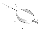
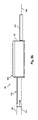
[0035] 最初に図1を参照すると、本開示の実施形態による脈管内システム100が示されている。それに関して、脈管内システムは、脈管内装置102及びコネクタ104を含む。以下にさらに詳細に考察するように、通信ケーブル105は、コネクタ104から、脈管内装置102の長手方向軸と同軸方向又は平行に延びる。通信ケーブル105が脈管内装置と同軸又は平行に延びる結果として、コネクタ104及び通信ケーブル105は、脈管内装置102を操作するときに、患者、患者の衣服、医療機器(チューブ、カテーテル、ワイヤ、リード等を含む)及び/又は処置室内のその他の構造物に引っ掛かり難い。
[0035] First, with reference to FIG. 1, an
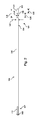
[0036] 次に図2を参照すると、脈管内装置102の側面図が、本開示の実施形態に従って提供されている。図示のように、脈管内装置102は、遠位端108に隣接する遠位部分107と、近位端110に隣接する近位部分109とを有する、可撓性の細長い部材106を含む。部品112は、遠位先端108の近位の可撓性の細長い部材106の遠位部分107内部に位置している。一般に、部品112は、1つ又は複数の電子、光学、又は電気光学部品を表わす。それに関して、部品112としては、圧力センサ、温度センサ、撮像素子、光ファイバ、超音波トランスデューサ、反射器、鏡、プリズム、アブレーション要素、RF電極、導体、及び/又はそれらの組合せを挙げることができる。特定のタイプの部品又は部品の組合せを、脈管内装置の意図する使用に基づいて、選択することができる。場合によっては、部品112は、遠位先端108から10cm未満、5cm未満、又は3cm未満に位置する。場合によっては、部品112は、脈管内装置102のハウジン部内部に位置する。それに関して、ハウジングは、場合によっては、可撓性の細長い部材106に固定された別個の部品とすることができる。他の場合には、ハウジングは、可撓性の細長い部材106の一部として一体的に形成することができる。
[0036] Next, with reference to FIG. 2, a side view of the
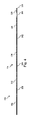
[0037] 脈管内装置102はまた、装置の近位部分109に隣接する接続部分114を含む。それに関して、接続部分114は、可撓性の細長い部材106の近位端110から、距離116だけ間隔を空けることができる。一般に、距離116は、可撓性の細長い部材106の全長の0%から50%の間である。可撓性の細長い部材の全長は、任意の長さとすることができるが、実施形態によっては、全長は、約1300mmから約4000mmの間であり、特定の実施形態の長さは、1400mm、1900mm、及び3000mmである。場合によっては、接続部分114は、近位端110から、約0mmから約1400mmの間で、間隔を空けられている。特定の実施形態においては、接続部分114は、近位端から、0mm、300mm、及び1400mmの距離だけ間隔を空けられている。したがって、場合によっては、接続部分114は、近位端110に位置する。そのような実施形態においては、以下で考察する脈管内装置102の係合及び位置合せ機構の1つ又は複数の態様は、図2の実施形態に示されるように、接続部分114の近位ではなく、接続部分114の遠位に位置するか、又は係合及び位置合せ機構は完全に省略される。
The
[0038] 図2に図示された実施形態において、脈管内装置102は、接続部分114から近位端110へと延びる別の部位120へと近位方向に延びる、部位118を含む。図示された実施形態において、部位120は、近位端110へと丸みがつけられている。他の実施形態において、部位120は、近位端110へと近位方向に延びるにつれて、テーパー状、弓形、及び/又はその他の変化するプロフィールを有する。それに関して、場合によっては、外部プロフィール及び/又は部位120の直径は、それが近位端110へと近位方向に延びるにつれて減少して、減少した近位端のプロフィール及び/又は直径によって、1つ又は複数の他の器具を脈管内装置の全体にわたり導入するのをより容易にするようにする。他の実施形態において、部位120は、近位端110へと近位方向に延びるときに、一定プロフィールを有する。
[0038] In the embodiment illustrated in FIG. 2, the
[0039] 図示されるように、接続部分114は、直径122(又は、非円形断面実施形態に対する外部断面プロフィールに対するその他類似の寸法)を有し、これに対して、部位118は直径124(ここでも、又は非円形断面実施形態に対する外部断面プロフィールに対するその他類似の寸法)を有する。部位118の直径124は、接続部分114の直径122とは異なる。それに関して、直径122、直径124のサイズが異なることによって、コネクタ104等のコネクタに対する、脈管内装置102の位置合せ及び/又は接続を容易にするように構成された、構造が作成される。図示された実施形態において、部位118の直径124は、接続部分114の直径122よりも小さい。実施形態によっては、部位118の直径124は、直径122の約40%から約80%の間であり、特定の実施形態では、直径122の約42%、64%、及び/又はその他の百分率である。それに関して、実施形態によっては、接続部分114の直径122は、約0.0178mmから約3.0mmの間であり、特定の実施形態では、0.3556mm(0.014”)及び0.4572mm(0.018”)である。したがって、実施形態によっては、部位118の直径124は、約0.007mmから約2.4mmの間であり、特定の実施形態では、0.15mm、0.19mm、0.23mm、及び0.29mmである。図示された実施形態では、部位120は、直径122にほぼ等しく、したがって直径124よりも大きい、直径を有する。しかしながら、他の実施形態において、部位120は、直径122よりも大きい、直径122よりも小さい、直径124よりも大きい、直径124に等しい、及び/又は直径124よりも小さい直径を有する。実施形態によっては、部位118は、接続部分114を通過して延びるコアワイヤの部位である。
[0039] As shown, the connecting
[0040] 図2に示されるように、部位118は、接続部分114から近位方向に距離126だけ延びており、一方で部位120は、部位118から近位端110へと距離128だけ延びている。合わせて、距離126及び128は、接続部分114が、脈管内装置102の近位端110から間隔を空けられている、距離に等しい。場合によっては、距離126は、約0.508mm(0.020”)から約2.54mm(0.10”)の間であり、特定の実施形態では、0.762mm(0.030”)、1.016mm(0.040”)、及び1.524mm(0.060”)である。さらに、接続部分114と部位118との間の遷移、並びに部位118と部位120との間の遷移が図示された実施形態において段差として示されているが、その他の実施形態においては、これらの遷移は、テーパー状であり、及び/又はその他の方法で、脈管内装置の長さに沿って外径を漸次的に変化させている。実現形態によっては、テーパー状遷移及び/又は漸次的遷移によって、脈管内装置102の近位部分にはいかなる鋭利な縁端もないという結果となる。実施形態によっては、部位118と、接続部分114又は部位120のいずれかとの間の遷移の一方又は両方に対して、テーパー状遷移及び/又は漸次的遷移を使用すると、装置の近位部分の洗浄(例えば、脈管内装置の近位部分の表面上の液体又はその他の不要な物質を除去すること)が容易になる。
[0040] As shown in FIG. 2, the
[0041] 接続部分114は、脈管内装置102と別の装置との間の通信を促進するように構成されている。より具体的には、実施形態によっては、接続部分114は、コンピュータ装置又はプロセッサ等の、別のデバイスへの、部品112によって取得されたデータの通信を促進するように構成されている。したがって、実施形態によっては、接続部分114は、電気コネクタである。そのような場合には、接続部分114は、可撓性の細長い部材106の長さに沿って延びて、部品112に電気的に結合されている、1つ又は複数の電気導体に電気的に接続するように構成することができる。例えば、接続部分114としては、導体バンド、リング、被覆、コイル、等を挙げることができる。場合によっては、接続部分114は、参照によりその全文が本明細書に組み入れられている、2013年6月28日出願の、「INTRAVASCULAR DEVICES,SYSTEMS,AND METHODS」という名称の米国特許出願第13/931052号(米国特許出願公開第2014/0005543号)に説明されているような、1つ又は複数の電気コネクタを含む。その他の実施形態においては、接続部分114は、光学コネクタを含む。そのような場合には、接続部分114は、可撓性の細長い部材106の長さに沿って延びて、部品112に光学的に結合されている、1つ又は複数の光学通信経路(例えば、光ファイバケーブル)への光学接続を提供する。さらに、実施形態によっては、接続部分114は、部品112に結合された、電気導体と光学通信経路の両方に、電気及び光学接続の両方を提供する。それに関して、ここでも、部品112は、場合によっては複数の要素で構成することもできることを注記すべきである。場合によっては、接続部分114は、直接的に、又は間接的にのいずれかで、別の装置への物理的接続を提供するように構成することができる。他の場合には、接続部分114は、脈管内装置102と別の装置との間のワイヤレス通信を促進するように構成することができる。一般的に、任意の現行の、又は将来開発されるワイヤレスプロトコルを利用してもよい。さらに別の場合には、接続部分114は、別の装置への物理的接続及びワイヤレス接続の両方を促進する。
[0041] The connecting
[0042] 上記のように、場合によっては、接続部分114は、脈管内装置102の部品112と外部装置との間に接続を行う。したがって、実施形態によっては、1つ又は複数の電気導体、1つ又は複数の光学経路、及び/又はそれらの組合せが、接続部分114と部品112との間で可撓性の細長い部材106の長さに沿って延びて、接続部分114と部品112との間の通信を促進する。一般的に、任意の数の電気導体、光学経路、及び/又はそれらの組合せを、接続部分114と部品112との間で可撓性の細長い部材106の長さに沿って延ばすことができる。場合によっては、1から10の間の電気導体及び/又は光学経路が、接続部分114と部品112との間で可撓性の細長い部材106の長さに沿って延びる。分かり易く、且つ簡潔にするために、以下に記述する本開示の実施形態は、3つの電気導体を含み、したがって、接続部分114は、3つの電気導体に対応する、3つの別個の電気接続を有するものとして説明される。
[0042] As described above, in some cases, the connecting
[0043] 例えば、図3に示されるように、場合によっては、接続部分114は、絶縁部分138、140、142、及び144によって、相互に、且つ可撓性の細長い部材106の本体から、離隔されている導電部分132、導電部分134及び導電部分136を含む。それに関して、導電部分132、導電部分134、及び導電部分136は、電導材料で形成され、場合によっては、ハイポチューブ(hypotube)、コイル、筒状部材の上に形成される電導被覆、及び/又はそれらの組合せの部分である。通信経路の総数並びに/又は電気導体及び/若しくは光学経路の数は、他の実施形態においては異なり、したがって、接続部分に含まれる導電部分(又は光学コネクタ)の数は、同様に異なるものと理解される。より具体的には、通信経路の数、並びに可撓性の細長い部材106の長さに沿って延びる電気導体及び光学経路の数を、部品112の所望の機能、及びそのような機能を提供するように部品112を画定する、対応する要素に基づいて選択することができる。結果として、接続部分114によって提供される接続の数及びタイプは、同様に、部品112の所望の機能、そのような機能を提供するように部品112を画定する対応する要素、及びそのような要素に対する通信ニーズによって同様に決定される。さらに、場合によっては、絶縁部分138、140、142、及び144の1つ又は複数が省略される。例えば、図4の例示的実施形態に示されているように、絶縁部分144が省略されている。
[0043] For example, as shown in FIG. 3, in some cases, the connecting
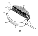
[0044] 図5、図6a及び図6bを参照すると、コネクタ104の追加の詳細が示されている。それに関して、図5は、開放位置におけるコネクタ104を示す、脈管内システム100の模式的な斜視上面図であり;図6aは、閉鎖位置におけるコネクタ104を示す、脈管内システム100の模式的な斜視上面図であり;図6bは、閉鎖位置におけるコネクタ104を示す、脈管内システム100の模式的側面図である。場合によっては、本出願のコネクタは、参照により本明細書にその全文を組み入れてある、2013年6月28日出願の「SIDE−LOADING CONNECTORS FOR USE WITH INTRAVASCULAR DEVICES AND ASSOCIATED SYSTEMS AND METHODS」という名称の、米国特許出願第13/930787号(米国特許出願公開第2014/0005573号)に説明されているコネクタの1つ又は複数の特徴を組み入れてある。それに関して、コネクタ104は、脈管内装置102の接続部分114とインターフェイスして、脈管内装置102と、患者インターフェイスモジュール(PIM)及び/又は処理システム等の、別個の部品との間の通信を促進するように構成されている。特に、コネクタ104は、接続部分114に電気的に結合されている脈管内装置102の1つ又は複数の電子部品と、患者インターフェイスモジュール(PIM)及び/又は1つ又は複数の電子部品に関連する処理システム等の、別個の部品との間の通信を促進するように構成されている。
[0044] With reference to FIGS. 5, 6a and 6b, additional details of
[0045] 図5に示されているように、コネクタ104は、部品152及び部品154を含む。図示された実施形態において、部品152は、部品154に対して可動である。特に、部品152及び部品154は、互いに摺動可能であって、脈管内装置のコネクタ104中への挿入と、その後のコネクタの、受け入れられた脈管内装置との係合とを容易にし、この係合によって、脈管内装置とコネクタとの間の1つ又は複数の電気接続が得られる。図示された実施形態において、部品152は、隆起文字によって示されてもよい把持機構を備える、上面を含む。それに関して、把持機構は、一般的には、任意のタイプの構造(例えば、突起、凹部、それらの組合せ、等)、テキスチャ(例えば、粗面化、ギザギザ成形(knurled)、パターン化、それらの組合せ等)、及び/又はユーザが部品152を部品154に対して平行移動させるか、又はその逆を行うのを補助するインターフェイスを提供するように構成された、それらの組合せを表わす。
[0045] As shown in FIG. 5,
[0046] 図5に示されるように、部品154は、脈管内装置を受け入れるように寸法及び形状が決められた凹部156を含む。特に、凹部156は、脈管内装置の接続部分を受け入れるように寸法及び形状が決められている。場合によっては、凹部156は、それぞれが参照によりその全文が本明細書に組み入れられている、「SIDE−LOADING CONNECTORS FOR USE WITH INTRAVASCULAR DEVICES AND ASSOCIATED SYSTEMS AND METHODS」という名称で、2013年6月28日出願の米国特許出願第13/930787号(米国特許出願公開第2014/0005573号)、及び/又は「SIDE−LOADING CONNECTORS FOR USE WITH INTRAVASCULAR DEVICES AND ASSOCIATED SYSTEMS AND METHODS」という名称で、2013年6月28日出願の米国特許出願第13/930636号(米国特許出願公開第2014/0005536号)に説明されているような特徴を含む。
[0046] As shown in FIG. 5,
[0047] 脈管内装置の接続部分がコネクタ104の電気接点と適正に位置合わせされることを確実にするために、部品152、部品154の一方又は両方は、1つ又は複数の視覚マーカー(能動的及び/又は受動的)を含み、且つ/又は少なくとも部分的に透明又は半透明の材料で形成されている。コネクタ104に対する脈管内装置102の位置合せによって、隣接する導体間のブリッジングを生じさせる可能性のある、脈管内装置102の表面上の液体を除去するための、1つ又は複数の払拭要素の使用を容易にすることもできる。それに関して、部品152、部品154は、1つ又は複数の視覚マーカー及び/又は位置合せを容易にする構造的部品、並びにそれぞれが参照によりその全文が本明細書に組み入れられている、「SIDE−LOADING CONNECTORS FOR USE WITH INTRAVASCULAR DEVICES AND ASSOCIATED SYSTEMS AND METHODS」という名称で、2013年6月28日出願の米国特許出願第13/930787号(米国特許出願公開第2014/0005573号)、及び/又は「SIDE−LOADING CONNECTORS FOR USE WITH INTRAVASCULAR DEVICES AND ASSOCIATED SYSTEMS AND METHODS」という名称で、2013年6月28日出願の米国特許出願第13/930636号(米国特許出願公開第2014/0005536号)に説明されているような1つ又は複数の払拭要素を含む。
[0047] To ensure that the connection portion of the intravascular device is properly aligned with the electrical contacts of the
[0048] 部品154に対する部品152の動きを誘導するために、実施形態によっては、部品152、部品154の一方又は両方は、他方の部品154、部品152の対応するスロット又は開口の内部に、それぞれ受け入れられる突起を含む。それに関して、スロット又は開口は、全体的に、部品の長さに沿って、部品の長手方向軸に平行な方向に延びている。突起は、部品152、部品154が互いに組み付けられると、突起が他方の部品の開口の内部に受け入れられるように、部品から延びている。それに関して、突起は、部品152が部品154に対して平行移動されるときに、突起が開口の長さに沿って平行移動できるように、開口の内部に摺動可能に受け入れられるような寸法及び形状にすることができる。場合によっては、開口の反対端は、部品154に対して、部品152の移動を制限する停止具としての役割をする。それに関して、突起は、部品152が完全に開放された位置にあるとき、開口の第1端と接触し、部品152が完全に閉鎖された位置にあるとき、第1端の反対側の開口の第2端に接触する。実施形態によっては、コネクタ104は、機構を閉鎖位置に軽くロックするために、バネのような付勢要素を含む。それに関して、付勢要素は、コネクタ104の部品152を、部品152、部品154間の摺動運動の少なくとも一部分を介して、閉鎖位置に向かって付勢することができる。
[0048] In order to guide the movement of the
[0049] 部品152は、脈管内装置102の接続部分114の導電部分132、導電部分134、及び導電部分136等の、対応する脈管内装置の電気接点を係合するように構成された、電気接点を含む。コネクタ104と脈管内装置との間の電気接続の任意の配設を使用してもよいことを理解されたい。それに関して、コネクタ104は、任意の数の電気接点(例えば、1、2、3、4、5、6、7、8、又は9以上の電気接点)を含むか、脈管内装置の1つ又は複数の導電部分のそれぞれのための単一接点を含むか、脈管内装置の1つ又は複数の導電部分のそれぞれのための複数接点、及び/又はそれらの組合せを含んでもよい。さらに、部品152には、限定ではなく、スプリット・オープン・コーム式電気接点、接触パッド、接触リング、接触バネ、及び/又はそれらの組合せを含む、任意好適な電気接点を含めることができる。実現形態によっては、電気接点は、電気的接続を維持しながら、脈管内装置102の回転を可能にするように構成される。
[0049] The
[0050] 図5、図6a及び図6bは、まとめて、開放位置(図5)から閉鎖位置(図6a及び図6b)へのコネクタ104の遷移を示す。図5に示されるように、コネクタ104は、側方装填式で、脈管内装置102を受け入れるように構成されている。より具体的には、脈管内装置102をその長手方向軸に対して横断方向に動かすことによって、脈管内装置102を、凹部156内部に着座させられるように部品152が開放位置へと後退させられると、部品154内の凹部156が露出される。コネクタ104内部に脈管内装置を装填するために、コネクタ104は、脈管内装置102に対して動かしてもよく、脈管内装置102をコネクタ104に対して動かしてもよく、且つ/又はそれの組合せとしてもよい。場合によっては、脈管内装置102が部品154の凹部156内部に位置する状態で、脈管内装置102が動かされて、部位120を部品154の外表面と係合させて、開放位置にある間に、脈管内装置を部品154に対して正しく位置合わせする。他の場合には、脈管内装置102は、部品152を閉鎖位置まで移行させた後まで、部位120を部品154の外表面と係合させるために動かすことがない。
[0050] FIGS. 5, 6a and 6b collectively show the transition of the
[0051] 脈管内装置102が部品154の凹部156内部に位置する状態で、部品154が、図5に矢印158で示されるように、部品152に対して、図6a及び図6bに示される閉鎖位置へと平行移動させられる。上記のように、実現形態によっては、コネクタ104は、付勢要素によって閉鎖位置に向かって付勢されている。閉鎖位置において、脈管内装置102は、コネクタ104が脈管内装置の接続部分114と電気的に通信するように、部品152と部品154との間に保持される。特に、閉鎖位置において、部品152の電気接点は、脈管内装置102の接続部分114と係合する。コネクタ104から脈管内装置102を切断して取り外すためには、部品154を、部品152に対して、図5の開放位置へと戻る反対方向に平行移動させる。
[0051] With the
[0052] 上記のように、コネクタ104は、脈管内装置の接続部分とインターフェイスして、脈管内装置と別個の部品との間の通信を促進するように構成されている。そのために、通信ケーブル105は、コネクタ104と別個の部品との間で信号を搬送するように構成されている。特に、通信ケーブル105は、電気信号を搬送するように構成されて、そのような電気通信を促進するためにその長さに沿って延びる1つ又は複数の電気導体を含む。しかしながら、使用される通信ケーブルのタイプは、脈管内装置に組み込まれている、電子、光学、及び/又は電気光学部品に依存する。それに関して、通信ケーブル105は、電気導体、光ファイバ、及び/又はそれらの組合せの内の1種又は複数種を含む。場合によっては、通信ケーブル105は、処理システムのインターフェイス中に差し込まれるように構成される。それに関して、インターフェイスは、場合によっては患者インターフェイスモジュール(PIM)である。
[0052] As described above, the
[0053] 図6a及び図6bに示されるように、通信ケーブル105は、通信ケーブル105の長手方向軸162が、コネクタ内部に受け入れられた脈管内装置102の長手方向軸160と同軸又は平行となるように、部品152から延びる。図6a及び図6bの図示された実施形態において、通信ケーブル105は、コネクタ104によって係合された脈管内装置102に平行に延びる。特に、図6aは、通信ケーブル105の長手方向軸162は、上から見たときに、脈管内装置102の長手方向軸160に対して位置合わせされていることを示すが、図6bは、通信ケーブル105の長手方向軸162は、横から(又は端から)見たときに、脈管内装置102の長手方向軸160に対して、距離164だけオフセットしていることを示す。したがって、図示された実施形態において、通信ケーブル105は、水平方向において脈管内装置102と位置合わせされており、垂直方向においてオフセットしていると考えられる。他の場合において、通信ケーブル105は、脈管内装置102と同軸である。さらに他の場合には、通信ケーブル105は、脈管内装置102に平行に延びるが、脈管内装置に対して、垂直及び水平方向の両方でオフセットしている。
As shown in FIGS. 6a and 6b, in the
[0054] 通信ケーブル105が、脈管内装置と同軸又は平行に延びている結果として、コネクタ104と脈管内装置102との間の接続の曲げモーメントが大きく低減される。特に、コネクタ104及び通信ケーブル105は、脈管内装置に直角な方向に延びるコネクタ及び/又は通信ケーブルと比較して、手術中に脈管内装置102を操作するときに、患者、患者の衣服、医療機器(チューブ、カテーテル、ワイヤ、リード等を含む)及び/又は処置室内のその他の構造物に引っ掛かり難い。したがって、本開示のコネクタは、医療専門家に対してより良好なユーザ体験を提供し、コネクタに結合されている間の脈管内装置の操作性を向上させ、処置中の脈管内装置及び/又はコネクタへの損傷の可能性を低下させ、これらのすべては患者の安全性と治療結果を向上させる。
As a result of the
[0055] 次に、図7〜図14を参照すると、本開示による代替的なコネクタを組み入れた脈管内システムの態様が示されている。図7及び図8を参照すると、本開示による脈管内装置102とコネクタ172とを有する脈管内システム170の態様が示されている。それに関して、コネクタ172は、コネクタ104について上記で説明されたものと類似の、多数の特徴を含み得る。したがって、以下の説明は、コネクタ104の特徴と異なる、コネクタ172の特徴に焦点を当てる。しかしながら、コネクタ104及びコネクタ172の両方の様々な特徴は、本開示と整合性のある、多様な方法の内の任意の方法で、組み合わせてもよいことを理解されたい。それに関して、特に断らない限りは、コネクタ104の任意の特徴は、コネクタ172内部に実現され、その逆も同様であると仮定するべきである。
[0055] Next, with reference to FIGS. 7-14, an embodiment of an intravascular system incorporating an alternative connector according to the present disclosure is shown. With reference to FIGS. 7 and 8, an embodiment of an
[0056] 図7に示されるように、コネクタ172は、ユーザによる把持のためのハンドル174を含む。ハンドルは、脈管内装置102を受け入れるように寸法及び形状が決められた凹部を含む、部品176に結合され、且つ/又は一体的に形成されている。コネクタ172はまた、部品176に対して可動である部品178を含む。特に、部品178は、部品176に対して回転可能であって、脈管内装置のコネクタ172中への挿入と、その後のコネクタの、受け入れられた脈管内装置との係合とを容易にし、この係合によって、脈管内装置とコネクタとの間の1つ又は複数の電気接続が得られる。部品176に対する部品178の回転軸は、ハンドル174の長手方向軸、及び/又はコネクタ172内部に受け入れられた脈管内装置の長手方向軸と同軸又は平行とすることができる。
[0056] As shown in FIG. 7, connector 172 includes a
[0057] 部品178には、部品176に対する部品178の回転を容易にするための、把持機構180を含めることができる。図示された実施形態において、把持機構180は、ユーザの親指又は指が、部品176に対する部品178の回転を起動することを可能にするように構成された、タブ又は突起である。それに関して、把持機構180は、一般的には、任意のタイプの構造(例えば、突起、凹部、それらの組合せ等)、テキスチャ(例えば、粗面化、ギザギザ成形、パターン化、それらの組合せ等)、及び/又はユーザが部品176に対して部品178を回転させるのを補助するインターフェイスを提供するように構成された、それらの組合せを表わす。
[0057] The
[0058] 部品178は、脈管内装置102の接続部分114の導電部分132、導電部分134、及び導電部分136等の、脈管内装置の対応する電気接点を係合するように構成された、電気接点を含む。したがって、部品178が、開放位置(図7)から閉鎖位置(図8)へと回転されるとき、矢印182で示されるように、部品178の電気接点は、部品176内部に受け入れられた脈管内装置102の対応する電気接点と係合して、通信経路を創出する。上記のように、コネクタ172は、脈管内装置の接続部分とインターフェイスして、脈管内装置と別個の部品との間の通信を促進するように構成されている。そのために、図8に示されるように、通信ケーブル105は、通信ケーブル105がコネクタ172内部に受け入れられた脈管内装置102と同軸又は平行になるように、ハンドル174から延びている。
[0058] The
[0059] 図9〜図11を参照すると、本開示による、脈管内装置102とコネクタ192とを有する、脈管内システム190の態様が示されている。それに関して、コネクタ192は、コネクタ104及びコネクタ172について上記で説明されたものに類似する、多数の特徴を含み得る。したがって、以下の説明は、コネクタ104及びコネクタ172の特徴と異なるコネクタ192の特徴に焦点を当てる。しかしながら、コネクタ104、コネクタ172、及びコネクタ192の様々な特徴は、本開示と整合性のある、多様な態様の内の任意の態様で、組み合わせてもよいことを理解されたい。それに関して、特に断らない限りは、コネクタ104、コネクタ172、及びコネクタ192の任意の特徴は、他のコネクタの内部に実現され、その逆も同様であると仮定するべきである。
[0059] With reference to FIGS. 9 to 11, an embodiment of an
[0060] 図9に示されるように、コネクタ192は、部品194及び部品196を含む。部品196は、脈管内装置102を受け入れるように寸法及び形状が決められた凹部198を含む。部品194は、部品196に対して可動である。特に、部品194は、部品196に対して枢動可能であり、脈管内装置のコネクタ192中への挿入と、その後のコネクタの、受け入れられた脈管内装置との係合とを容易にして、この係合によって、脈管内装置とコネクタとの間の1つ又は複数の電気接続が得られる。部品196に対する部品194の枢動軸は、部品196の長手方向軸及び/又はコネクタ192内部に受け入れられた脈管内装置の長手方向軸に直角にすることができる。
[0060] As shown in FIG. 9,
[0061] 部品194は、脈管内装置102の接続部分114の導電部分132、導電部分134、及び導電部分136等の、対応する脈管内装置の電気接点を係合するように構成された、電気接点を含む。したがって、部品178が、開放位置(図9及び図10)から閉鎖位置(図11)へと枢動されると、矢印199で示されるように、部品194の電気接点は、部品196内部に受け入れられた脈管内装置102の対応する電気接点と係合して、通信経路を創出する。場合によっては、コネクタ192は、図11の閉鎖位置に向かって付勢される。例えば、ばね等の付勢要素が、部品194及び部品196を閉鎖位置に向かって付勢することができる。上記のように、コネクタ192は、脈管内装置の接続部分とインターフェイスするように構成されて、脈管内装置と別個の部品との間の通信を促進する。そのために、図9〜図11に示されるように、通信ケーブル105は、通信ケーブル105が、コネクタ192内部に受け入れられた脈管内装置102と同軸又は平行になるように、コネクタ192から延びている。
[0061] The
[0062] 図12〜図14を参照すると、本開示による、脈管内装置102とコネクタ202とを有する、脈管内システム200の態様が示されている。それに関して、コネクタ202は、コネクタ104、コネクタ172、及びコネクタ192について上記で説明されたものに類似する、多数の特徴を含み得る。したがって、以下の説明は、コネクタ104、コネクタ172、及びコネクタ192の特徴と異なるコネクタ202の特徴に焦点を当てる。しかしながら、コネクタ104、コネクタ172、コネクタ192、及び202の様々な特徴は、本開示と整合性のある、多様な方法の内の任意の方法で、組み合わせてもよいことを理解されたい。それに関して、特に断らない限りは、コネクタ104、コネクタ172、コネクタ192、及びコネクタ202の任意の特徴は、他のコネクタの内部に実現され、その逆も同様であると仮定するべきである。
[0062] With reference to FIGS. 12-14, an embodiment of an
[0063] 図12〜図14に示されるように、コネクタ202は、部品204及び部品206を含む。部品204は、脈管内装置102を受け入れるように寸法及び形状を決められた凹部208を含む。部品206は、部品204に対して可動である。特に、部品206は、部品204に対して摺動可能であって、脈管内装置のコネクタ202中への挿入と、その後のコネクタの、受け入れられた脈管内装置との係合とを容易にし、この係合によって、脈管内装置とコネクタとの間の1つ又は複数の電気接続が得られる。部品204に対する部品206の摺動運動の方向は、部品204の長手方向軸及び/又はコネクタ202内部に受け入れられた脈管内装置の長手方向軸に平行とすることができる。
[0063] As shown in FIGS. 12-14,
[0064] 部品206は、脈管内装置102の接続部分114の導電部分132、導電部分134、及び導電部分136等の、脈管内装置の対応する電気接点を係合するように構成された、電気接点210を含む。特に、図14に最も分かり易く示されるように、部品206は、スプリット・オープン・コーム式電気接点210を含む。それに関して、電気接点210の各々は、オープン・コーム式電気接点の歯の一部が、導電部分の上に位置し、オープン・コーム式電気接点の歯の残部が導電部分の下に位置するように、脈管内装置の導電部分をその中に受け入れるように構成することができる。この配設は、コネクタ202の電気接点210と、脈管内装置の対応する導電部分との間の安全で確実な電気接続を提供する。
[0064] The
[0065] さらに、オープン・コーム式電気接点は、部品206が、開放位置から閉鎖位置に向かって部品204に対して平行移動させられるときに、コネクタ202と、部品204の凹部208内部に位置する脈管内装置102との間の適正な電気接続を促進するのに特に適している。さらに、オープン・コーム構成は、脈管内装置が、適正な電気接続を維持しながらコネクタに対して回転されることを可能にする。すなわち、オープン・コーム構成は、ユーザ(例えば、外科医)が、脈管内装置の回転運動に対してほとんど抵抗無しに脈管内装置が脈管中を移動又は前進される間に、コネクタ202を脈管内装置に接続したままで保つことを可能にする。言い換えると、脈管内装置は、コネクタ202が脈管内装置の回転と共に動くことを必要とすることなしに、様々な曲折を受け、脈管中を動かすことができる。また、オープン・コーム構成は、接点の各々に対する複数フィンガによって、良好な電気接触を確保できるようにする。さらに、オープン・コーム構成の開放端は、部品206が閉鎖されるときに、脈管内装置が正しく位置することを確実にするための良好なガイドを提供する。オープン・コーム構成の様々な利点を説明したが、単一接点又は複数の接点を含み、任意の、適当な寸法にされた電気接点を使用することができることを理解されたい。
[0065] Further, the open comb electrical contacts are located inside the
[0066] 部品206が開放位置(図12)から閉鎖位置(図13及び図14)まで平行移動させられるとき、部品206の電気接点210は、部品204内部に受け入れられた脈管内装置102の対応する電気接点と係合して、通信経路を創出する。さらに、部品206の部位212は、部品204の凹部208の上に延びて、コネクタ202内部の脈管内装置102を固定して、電気通信に被害を与えるか、又はそれと干渉する、流体及び/又はその他の潜在的汚染物から電気接続を保護する。場合によっては、コネクタ202は、図14の閉鎖位置に向かって付勢される。例えば、ばね等の付勢要素214は、部品204及び部品206を閉鎖位置に向かって付勢することができる。したがって、部品206を開放位置へ動かすために、ユーザは、付勢要素214に逆らって、矢印216の方向に部品206を前進させる。図12に示されるように、開放位置において、部品206の部位212は、部品206内の開口218が凹部208の上に位置して、脈管内装置102を受け入れるためのコネクタ202中への経路を画定するように、部品204の凹部208から間隔を空けられている。これに関して、図14を参照すると、開放位置において、部品206の部位212は、部品204の部位220の下に位置する。
[0066] When the
[0067] ここでも、コネクタ202は、脈管内装置の接続部分とインターフェイスして、脈管内装置と別個の部品との間の通信を促進するように構成されている。そのために、図12及び図13に示されるように、通信ケーブル105は、通信ケーブル105が、コネクタ202内部に受け入れられた脈管内装置102と同軸又は平行になるように、コネクタ202から延びる。
[0067] Again, the
[0068] 当業者はまた、上記で説明された装置、システム、及び方法は様々な手法で修正することができることを認識するであろう。したがって、当業者は、本開示によって包含される実施形態は、上述の特定の例示的実施形態に限定されるものではないことに気付くであろう。それに関して、例証的な実施形態を示して説明したが、広範囲の修正、変更、及び置換が、前述の開示において検討される。本開示の範囲から逸脱することなく、そのような変形を、前述の開示に対して行うことができることを理解されたい。したがって、添付の特許請求の範囲は広義に、且つ本開示と整合して解釈するのが適当である。 Those skilled in the art will also recognize that the devices, systems, and methods described above can be modified in a variety of ways. Accordingly, one of ordinary skill in the art will appreciate that the embodiments included in the present disclosure are not limited to the particular exemplary embodiments described above. In that regard, although exemplary embodiments have been described, a wide range of modifications, changes, and substitutions are considered in the disclosures described above. It should be understood that such modifications can be made to the aforementioned disclosures without departing from the scope of this disclosure. Therefore, it is appropriate to interpret the appended claims in a broad sense and in line with the present disclosure.
Claims (15)
前記可撓性の細長い部材の前記遠位部分に固定された少なくとも1つの電子部品と、
前記可撓性の細長い部材の前記近位部分に固定された少なくとも1つの電気コネクタであって、前記可撓性の細長い部材の前記遠位部分に固定された前記少なくとも1つの電子部品に電気的に結合された、前記少なくとも1つの電気コネクタとを有する、
脈管内装置と、
前記可撓性の細長い部材の前記近位部分へ結合するためのコネクタであって、
凹部及び第1の開口を含む第1の接続ピースと、
第2の開口を含み、開放位置と閉鎖位置との間で前記第1の接続ピースに対して平行移動可能である第2の接続ピースであって、前記閉鎖位置は前記第2の接続ピースにより前記凹部が閉鎖される位置であり、前記開放位置は前記凹部が前記第2の接続ピースから開放される位置である、前記第2の接続ピースと、
前記脈管内装置の前記少なくとも1つの電気コネクタとインターフェイスする、前記第2の接続ピースに固定された少なくとも1つの電気接点とを有する、
前記コネクタとを備え、
前記開放位置において、前記第1の開口と前記凹部との間に前記第2の開口があるように前記第1の接続ピースの前記第1の開口が前記第2の接続ピースの前記第2の開口と少なくとも部分的に位置合わせされて前記凹部が開放されることにより、前記脈管内装置が前記凹部に受け入れられて、前記第1の接続ピースの前記凹部中への前記脈管内装置の前記少なくとも1つの電気コネクタの挿入を容易にし、
前記閉鎖位置において、前記第2の接続ピースが平行移動して前記凹部を閉鎖したとき、前記第2の接続ピースに固定された前記少なくとも1つの電気接点が、前記凹部中へ挿入された前記脈管内装置の前記少なくとも1つの電気コネクタに電気的に結合され、通信ケーブルが、前記コネクタから、前記脈管内装置とは逆方向に、前記脈管内装置の長手方向軸と同軸又は平行に延びる、システム。 A flexible elongated member having a proximal part and a distal part,
With at least one electronic component fixed to the distal portion of the flexible elongated member,
At least one electrical connector fixed to the proximal portion of the flexible elongated member and electrically to the at least one electronic component fixed to the distal portion of the flexible elongated member. With at least one electrical connector coupled to the
Intravascular device and
A connector for connecting to the proximal portion of the flexible elongated member.
With a first connecting piece, including a recess and a first opening,
A second connecting piece that includes a second opening and is translatable with respect to the first connecting piece between the open and closed positions, the closed position being driven by the second connecting piece. The second connection piece, which is a position where the recess is closed, and the open position is a position where the recess is opened from the second connection piece.
It has at least one electrical contact fixed to the second connecting piece that interfaces with the at least one electrical connector of the intravascular device.
With the connector
In the open position, the first opening of the first connecting piece is the second opening of the second connecting piece so that the second opening is between the first opening and the recess. By opening the recess so that it is at least partially aligned with the opening, the intravascular device is received into the recess and at least the intravascular device into the recess of the first connector piece. Facilitates the insertion of one electrical connector,
When the second connecting piece moves in parallel to close the recess in the closed position, the pulse in which at least one electrical contact fixed to the second connecting piece is inserted into the recess. A system that is electrically coupled to the at least one electrical connector of the intraductal device and the communication cable extends from the connector in the direction opposite to the intravascular device and coaxially or parallel to the longitudinal axis of the intravascular device. ..
第2の開口を含み、開放位置と閉鎖位置との間で前記第1の接続ピースに対して平行移動可能である第2の接続ピースであって、前記閉鎖位置は前記第2の接続ピースにより前記凹部が閉鎖される位置であり、前記開放位置は前記凹部が前記第2の接続ピースから開放される位置である、前記第2の接続ピースと、
脈管内装置の少なくとも1つの電気コネクタとインターフェイスする、前記第2の接続ピースに固定された少なくとも1つの電気接点とを含み、
前記開放位置において、前記第1の開口と前記凹部との間に前記第2の開口があるように前記第1の接続ピースの前記第1の開口が前記第2の接続ピースの前記第2の開口と少なくとも部分的に位置合わせされて前記凹部が開放されることにより、前記脈管内装置が前記凹部に受け入れられて、前記第1の接続ピースの前記凹部中への前記脈管内装置の前記少なくとも1つの電気コネクタの挿入を容易にし、
前記閉鎖位置において、前記第2の接続ピースが平行移動して前記凹部を閉鎖したとき、前記第2の接続ピースに固定された前記少なくとも1つの電気接点が、前記凹部中へ挿入された前記脈管内装置の前記少なくとも1つの電気コネクタに電気的に結合され、通信ケーブルが、前記コネクタから、前記脈管内装置とは逆方向に、前記脈管内装置の長手方向軸と同軸又は平行に延びる、脈管内システム用のコネクタ。 With a first connecting piece, including a recess and a first opening,
A second connecting piece that includes a second opening and is translatable with respect to the first connecting piece between the open and closed positions, the closed position being driven by the second connecting piece. The second connection piece, which is a position where the recess is closed, and the open position is a position where the recess is opened from the second connection piece.
Includes at least one electrical contact secured to the second connecting piece that interfaces with at least one electrical connector of the intravascular device.
In the open position, the first opening of the first connecting piece is the second opening of the second connecting piece so that the second opening is between the first opening and the recess. By opening the recess so that it is at least partially aligned with the opening, the intravascular device is received into the recess and at least the intravascular device into the recess of the first connector piece. Facilitates the insertion of one electrical connector,
When the second connecting piece moves in parallel to close the recess in the closed position, the pulse in which at least one electrical contact fixed to the second connecting piece is inserted into the recess. said tube device is electrically coupled to at least one electrical connector, communication cable, from the connector, in a direction opposite to the said intravascular device, the longitudinal axis and extending coaxially or parallel of the intravascular device, pulse Connector for in-pipe system.
Applications Claiming Priority (3)
| Application Number | Priority Date | Filing Date | Title |
|---|---|---|---|
| US201562199708P | 2015-07-31 | 2015-07-31 | |
| US62/199,708 | 2015-07-31 | ||
| PCT/IB2016/054528 WO2017021834A1 (en) | 2015-07-31 | 2016-07-28 | Side-loading connectors with inline cabling for use with intravascular devices and associated systems and methods |
Publications (3)
| Publication Number | Publication Date |
|---|---|
| JP2018528802A JP2018528802A (en) | 2018-10-04 |
| JP2018528802A5 JP2018528802A5 (en) | 2019-06-27 |
| JP6878404B2 true JP6878404B2 (en) | 2021-05-26 |
Family
ID=56853683
Family Applications (1)
| Application Number | Title | Priority Date | Filing Date |
|---|---|---|---|
| JP2018504166A Active JP6878404B2 (en) | 2015-07-31 | 2016-07-28 | Side-loading connectors with in-line cables for use in intravascular devices and related systems and methods |
Country Status (5)
| Country | Link |
|---|---|
| US (1) | US10342490B2 (en) |
| EP (1) | EP3328270B1 (en) |
| JP (1) | JP6878404B2 (en) |
| CN (1) | CN107847151B (en) |
| WO (1) | WO2017021834A1 (en) |
Families Citing this family (3)
| Publication number | Priority date | Publication date | Assignee | Title |
|---|---|---|---|---|
| CN111315285B (en) * | 2017-08-31 | 2023-06-06 | 皇家飞利浦有限公司 | Sensing guidewire with integrated proximal locking feature |
| CN112074230A (en) * | 2018-02-20 | 2020-12-11 | 巴德阿克塞斯系统股份有限公司 | Connection system for establishing an electrical connection across a sterile field and method therefor |
| US20210196370A1 (en) * | 2019-12-30 | 2021-07-01 | Biosense Webster (Israel) Ltd. | Neurosurgery guidewire with integral connector for sensing and applying therapeutic electrical energy |
Family Cites Families (20)
| Publication number | Priority date | Publication date | Assignee | Title |
|---|---|---|---|---|
| IE911159A1 (en) * | 1990-07-23 | 1992-01-29 | Bard Inc C R | System and technique for measuring blood characteristics by¹centering a sensor in an artery |
| US5931861A (en) | 1997-04-25 | 1999-08-03 | Medtronic, Inc. | Medical lead adaptor having rotatable locking clip mechanism |
| EP1267751A2 (en) * | 2000-03-22 | 2003-01-02 | Advanced Stent Technologies LLC | Guidewire introducer sheath |
| US20020072712A1 (en) * | 2000-10-12 | 2002-06-13 | Nool Jeffrey A. | Medical wire introducer and protective sheath |
| CA2468252A1 (en) * | 2000-11-20 | 2002-05-23 | Surgi-Vision, Inc. | Connector and guidewire connectable thereto |
| US20030199948A1 (en) | 2002-04-19 | 2003-10-23 | Kokones Scott B. | Multiport neurological screening cable |
| US6980863B2 (en) | 2003-03-20 | 2005-12-27 | Medtronic, Inc. | Neurological stimulation lead extension |
| AU2005211666B2 (en) * | 2004-11-09 | 2011-01-06 | St. Jude Medical Coordination Center Bvba | Reducing leakage current in guide wire assembly |
| US7784662B2 (en) * | 2005-02-18 | 2010-08-31 | Ethicon Endo-Surgery, Inc. | Surgical instrument with articulating shaft with single pivot closure and double pivot frame ground |
| JP4972639B2 (en) * | 2005-05-06 | 2012-07-11 | バソノバ・インコーポレイテッド | Method and apparatus for guiding and positioning an intravascular device |
| US20070255145A1 (en) * | 2006-04-28 | 2007-11-01 | Radi Medical Systems Ab | Sensor and guide wire assembly |
| US20100273355A1 (en) * | 2009-04-22 | 2010-10-28 | Tyco Electronics Corporation | Image guide wire connection |
| US8359098B2 (en) * | 2009-05-29 | 2013-01-22 | Medtronic, Inc. | Implantable medical device with exposed generator |
| US9388929B2 (en) * | 2009-12-09 | 2016-07-12 | Nordson Corporation | Male bayonet connector |
| JP2013538600A (en) * | 2010-08-13 | 2013-10-17 | キャスアールエックス リミテッド | Catheter electrical connector assembly |
| JP6066935B2 (en) * | 2011-03-08 | 2017-01-25 | コーエン,トッド,ジェイ. | Ablation catheter system with safety function |
| WO2014005012A1 (en) | 2012-06-28 | 2014-01-03 | Volcano Corporation | Intravascular devices, systems, and methods |
| US20140005573A1 (en) | 2012-06-28 | 2014-01-02 | Volcano Corporation | Side-Loading Connectors for Use With Intravascular Devices and Associated Systems and Methods |
| US9427163B2 (en) * | 2012-06-28 | 2016-08-30 | Volcano Corporation | Side-loading connectors for use with intravascular devices and associated systems and methods |
| CN102908191A (en) * | 2012-11-13 | 2013-02-06 | 陈绍良 | Multipolar synchronous pulmonary artery radiofrequency ablation catheter |
-
2016
- 2016-07-28 WO PCT/IB2016/054528 patent/WO2017021834A1/en active Application Filing
- 2016-07-28 JP JP2018504166A patent/JP6878404B2/en active Active
- 2016-07-28 US US15/749,091 patent/US10342490B2/en active Active
- 2016-07-28 CN CN201680044958.8A patent/CN107847151B/en active Active
- 2016-07-28 EP EP16760172.3A patent/EP3328270B1/en active Active
Also Published As
| Publication number | Publication date |
|---|---|
| US10342490B2 (en) | 2019-07-09 |
| US20180220969A1 (en) | 2018-08-09 |
| EP3328270A1 (en) | 2018-06-06 |
| JP2018528802A (en) | 2018-10-04 |
| WO2017021834A1 (en) | 2017-02-09 |
| EP3328270B1 (en) | 2022-04-27 |
| CN107847151A (en) | 2018-03-27 |
| CN107847151B (en) | 2021-06-01 |
Similar Documents
| Publication | Publication Date | Title |
|---|---|---|
| JP6925383B2 (en) | Lateral loading connectors and related systems and methods for use with intravascular devices | |
| US9554710B2 (en) | Side-loading connectors for use with intravascular devices and associated systems and methods | |
| US20230321398A1 (en) | Torque devices for use with intravascular devices and associated systems and methods | |
| JP7372907B2 (en) | Sensing guidewire with integrated proximal locking feature | |
| JP6878404B2 (en) | Side-loading connectors with in-line cables for use in intravascular devices and related systems and methods | |
| US20140180139A1 (en) | Connectors for Use With Intravascular Devices and Associated Systems and Methods |
Legal Events
| Date | Code | Title | Description |
|---|---|---|---|
| A521 | Request for written amendment filed |
Free format text: JAPANESE INTERMEDIATE CODE: A523 Effective date: 20190527 |
|
| A621 | Written request for application examination |
Free format text: JAPANESE INTERMEDIATE CODE: A621 Effective date: 20190527 |
|
| A871 | Explanation of circumstances concerning accelerated examination |
Free format text: JAPANESE INTERMEDIATE CODE: A871 Effective date: 20190527 |
|
| A975 | Report on accelerated examination |
Free format text: JAPANESE INTERMEDIATE CODE: A971005 Effective date: 20190618 |
|
| A131 | Notification of reasons for refusal |
Free format text: JAPANESE INTERMEDIATE CODE: A131 Effective date: 20190705 |
|
| A521 | Request for written amendment filed |
Free format text: JAPANESE INTERMEDIATE CODE: A523 Effective date: 20191001 |
|
| A02 | Decision of refusal |
Free format text: JAPANESE INTERMEDIATE CODE: A02 Effective date: 20191119 |
|
| A521 | Request for written amendment filed |
Free format text: JAPANESE INTERMEDIATE CODE: A523 Effective date: 20200317 |
|
| C60 | Trial request (containing other claim documents, opposition documents) |
Free format text: JAPANESE INTERMEDIATE CODE: C60 Effective date: 20200317 |
|
| A911 | Transfer to examiner for re-examination before appeal (zenchi) |
Free format text: JAPANESE INTERMEDIATE CODE: A911 Effective date: 20200324 |
|
| C21 | Notice of transfer of a case for reconsideration by examiners before appeal proceedings |
Free format text: JAPANESE INTERMEDIATE CODE: C21 Effective date: 20200330 |
|
| A912 | Re-examination (zenchi) completed and case transferred to appeal board |
Free format text: JAPANESE INTERMEDIATE CODE: A912 Effective date: 20200515 |
|
| C211 | Notice of termination of reconsideration by examiners before appeal proceedings |
Free format text: JAPANESE INTERMEDIATE CODE: C211 Effective date: 20200522 |
|
| C22 | Notice of designation (change) of administrative judge |
Free format text: JAPANESE INTERMEDIATE CODE: C22 Effective date: 20200622 |
|
| C13 | Notice of reasons for refusal |
Free format text: JAPANESE INTERMEDIATE CODE: C13 Effective date: 20201006 |
|
| A521 | Request for written amendment filed |
Free format text: JAPANESE INTERMEDIATE CODE: A523 Effective date: 20201221 |
|
| C23 | Notice of termination of proceedings |
Free format text: JAPANESE INTERMEDIATE CODE: C23 Effective date: 20210222 |
|
| C03 | Trial/appeal decision taken |
Free format text: JAPANESE INTERMEDIATE CODE: C03 Effective date: 20210401 |
|
| C30A | Notification sent |
Free format text: JAPANESE INTERMEDIATE CODE: C3012 Effective date: 20210401 |
|
| A61 | First payment of annual fees (during grant procedure) |
Free format text: JAPANESE INTERMEDIATE CODE: A61 Effective date: 20210428 |
|
| R150 | Certificate of patent or registration of utility model |
Ref document number: 6878404 Country of ref document: JP Free format text: JAPANESE INTERMEDIATE CODE: R150 |