JP6876122B2 - Wireless speaker devices for wireless audio / video recording and communication devices - Google Patents
Wireless speaker devices for wireless audio / video recording and communication devices Download PDFInfo
- Publication number
- JP6876122B2 JP6876122B2 JP2019503206A JP2019503206A JP6876122B2 JP 6876122 B2 JP6876122 B2 JP 6876122B2 JP 2019503206 A JP2019503206 A JP 2019503206A JP 2019503206 A JP2019503206 A JP 2019503206A JP 6876122 B2 JP6876122 B2 JP 6876122B2
- Authority
- JP
- Japan
- Prior art keywords
- wireless
- recording
- doorbell
- radio
- communication
- Prior art date
- Legal status (The legal status is an assumption and is not a legal conclusion. Google has not performed a legal analysis and makes no representation as to the accuracy of the status listed.)
- Active
Links
- 238000004891 communication Methods 0.000 title claims description 310
- 238000000034 method Methods 0.000 claims description 64
- 238000001514 detection method Methods 0.000 claims description 42
- 230000033001 locomotion Effects 0.000 claims description 38
- 230000004044 response Effects 0.000 claims description 35
- 238000012545 processing Methods 0.000 claims description 11
- 238000003825 pressing Methods 0.000 claims description 6
- 230000000737 periodic effect Effects 0.000 claims 1
- 230000015654 memory Effects 0.000 description 71
- 230000008569 process Effects 0.000 description 46
- 238000010586 diagram Methods 0.000 description 30
- 238000003860 storage Methods 0.000 description 21
- 230000005540 biological transmission Effects 0.000 description 18
- 230000006870 function Effects 0.000 description 18
- CTVRBEKNQHJPLX-UHFFFAOYSA-N 1,2,5-trichloro-3-(2,4,6-trichlorophenyl)benzene Chemical compound ClC1=CC(Cl)=CC(Cl)=C1C1=CC(Cl)=CC(Cl)=C1Cl CTVRBEKNQHJPLX-UHFFFAOYSA-N 0.000 description 14
- LKHLFUVHHXCNJH-UHFFFAOYSA-N 1,2,4-trichloro-3-(2,4,5-trichlorophenyl)benzene Chemical compound C1=C(Cl)C(Cl)=CC(Cl)=C1C1=C(Cl)C=CC(Cl)=C1Cl LKHLFUVHHXCNJH-UHFFFAOYSA-N 0.000 description 13
- 238000012546 transfer Methods 0.000 description 10
- 238000007726 management method Methods 0.000 description 9
- 239000000463 material Substances 0.000 description 9
- 230000001960 triggered effect Effects 0.000 description 9
- 239000000853 adhesive Substances 0.000 description 8
- 230000001070 adhesive effect Effects 0.000 description 8
- 238000004590 computer program Methods 0.000 description 8
- BQHCQAQLTCQFJZ-UHFFFAOYSA-N 1,2,4-trichloro-5-(2,3,5-trichlorophenyl)benzene Chemical compound ClC1=CC(Cl)=C(Cl)C(C=2C(=CC(Cl)=C(Cl)C=2)Cl)=C1 BQHCQAQLTCQFJZ-UHFFFAOYSA-N 0.000 description 7
- 230000004913 activation Effects 0.000 description 7
- AQONCPKMJSBHQT-UHFFFAOYSA-N 1,2,4,5-tetrachloro-3-(2,4-dichlorophenyl)benzene Chemical compound ClC1=CC(Cl)=CC=C1C1=C(Cl)C(Cl)=CC(Cl)=C1Cl AQONCPKMJSBHQT-UHFFFAOYSA-N 0.000 description 6
- 239000008186 active pharmaceutical agent Substances 0.000 description 6
- 238000005516 engineering process Methods 0.000 description 6
- 230000003287 optical effect Effects 0.000 description 6
- 230000002085 persistent effect Effects 0.000 description 6
- 230000002093 peripheral effect Effects 0.000 description 5
- 229920003023 plastic Polymers 0.000 description 5
- 230000001413 cellular effect Effects 0.000 description 4
- 238000003384 imaging method Methods 0.000 description 4
- 238000003780 insertion Methods 0.000 description 4
- 230000037431 insertion Effects 0.000 description 4
- 239000004033 plastic Substances 0.000 description 4
- 230000001360 synchronised effect Effects 0.000 description 4
- 230000007704 transition Effects 0.000 description 4
- RYGMFSIKBFXOCR-UHFFFAOYSA-N Copper Chemical compound [Cu] RYGMFSIKBFXOCR-UHFFFAOYSA-N 0.000 description 3
- 239000004606 Fillers/Extenders Substances 0.000 description 3
- 230000009471 action Effects 0.000 description 3
- 230000003044 adaptive effect Effects 0.000 description 3
- 229910052782 aluminium Inorganic materials 0.000 description 3
- XAGFODPZIPBFFR-UHFFFAOYSA-N aluminium Chemical compound [Al] XAGFODPZIPBFFR-UHFFFAOYSA-N 0.000 description 3
- 230000008859 change Effects 0.000 description 3
- 229910052802 copper Inorganic materials 0.000 description 3
- 239000010949 copper Substances 0.000 description 3
- 238000013500 data storage Methods 0.000 description 3
- 230000006266 hibernation Effects 0.000 description 3
- 229910052751 metal Inorganic materials 0.000 description 3
- 239000002184 metal Substances 0.000 description 3
- 229910001092 metal group alloy Inorganic materials 0.000 description 3
- 150000002739 metals Chemical class 0.000 description 3
- 230000004297 night vision Effects 0.000 description 3
- 239000004065 semiconductor Substances 0.000 description 3
- 230000003190 augmentative effect Effects 0.000 description 2
- 230000008901 benefit Effects 0.000 description 2
- 239000004020 conductor Substances 0.000 description 2
- 230000004438 eyesight Effects 0.000 description 2
- 239000000835 fiber Substances 0.000 description 2
- 230000001965 increasing effect Effects 0.000 description 2
- 230000010354 integration Effects 0.000 description 2
- 239000000203 mixture Substances 0.000 description 2
- 238000012986 modification Methods 0.000 description 2
- 230000004048 modification Effects 0.000 description 2
- 229910001220 stainless steel Inorganic materials 0.000 description 2
- 239000010935 stainless steel Substances 0.000 description 2
- -1 stucco Substances 0.000 description 2
- 230000002459 sustained effect Effects 0.000 description 2
- 230000000007 visual effect Effects 0.000 description 2
- XLYOFNOQVPJJNP-UHFFFAOYSA-N water Chemical compound O XLYOFNOQVPJJNP-UHFFFAOYSA-N 0.000 description 2
- 239000004698 Polyethylene Substances 0.000 description 1
- 230000001133 acceleration Effects 0.000 description 1
- 239000004676 acrylonitrile butadiene styrene Substances 0.000 description 1
- 230000006399 behavior Effects 0.000 description 1
- 230000009286 beneficial effect Effects 0.000 description 1
- 230000004397 blinking Effects 0.000 description 1
- 239000011449 brick Substances 0.000 description 1
- 230000000295 complement effect Effects 0.000 description 1
- 230000006835 compression Effects 0.000 description 1
- 238000007906 compression Methods 0.000 description 1
- 230000008878 coupling Effects 0.000 description 1
- 238000010168 coupling process Methods 0.000 description 1
- 238000005859 coupling reaction Methods 0.000 description 1
- 230000003247 decreasing effect Effects 0.000 description 1
- 230000002708 enhancing effect Effects 0.000 description 1
- 230000005484 gravity Effects 0.000 description 1
- 238000005286 illumination Methods 0.000 description 1
- 239000004973 liquid crystal related substance Substances 0.000 description 1
- 238000004519 manufacturing process Methods 0.000 description 1
- 229910044991 metal oxide Inorganic materials 0.000 description 1
- 150000004706 metal oxides Chemical class 0.000 description 1
- 238000010295 mobile communication Methods 0.000 description 1
- 238000012544 monitoring process Methods 0.000 description 1
- 230000006855 networking Effects 0.000 description 1
- 239000004417 polycarbonate Substances 0.000 description 1
- 229920000515 polycarbonate Polymers 0.000 description 1
- 229920000573 polyethylene Polymers 0.000 description 1
- 230000000644 propagated effect Effects 0.000 description 1
- 238000011160 research Methods 0.000 description 1
- 230000005236 sound signal Effects 0.000 description 1
- 238000012795 verification Methods 0.000 description 1
- 125000000391 vinyl group Chemical group [H]C([*])=C([H])[H] 0.000 description 1
- 229920002554 vinyl polymer Polymers 0.000 description 1
- 238000001429 visible spectrum Methods 0.000 description 1
- 230000001755 vocal effect Effects 0.000 description 1
- 239000002023 wood Substances 0.000 description 1
Images


Classifications
-
- G—PHYSICS
- G08—SIGNALLING
- G08B—SIGNALLING OR CALLING SYSTEMS; ORDER TELEGRAPHS; ALARM SYSTEMS
- G08B3/00—Audible signalling systems; Audible personal calling systems
- G08B3/10—Audible signalling systems; Audible personal calling systems using electric transmission; using electromagnetic transmission
-
- G—PHYSICS
- G08—SIGNALLING
- G08B—SIGNALLING OR CALLING SYSTEMS; ORDER TELEGRAPHS; ALARM SYSTEMS
- G08B13/00—Burglar, theft or intruder alarms
- G08B13/18—Actuation by interference with heat, light, or radiation of shorter wavelength; Actuation by intruding sources of heat, light, or radiation of shorter wavelength
- G08B13/189—Actuation by interference with heat, light, or radiation of shorter wavelength; Actuation by intruding sources of heat, light, or radiation of shorter wavelength using passive radiation detection systems
- G08B13/194—Actuation by interference with heat, light, or radiation of shorter wavelength; Actuation by intruding sources of heat, light, or radiation of shorter wavelength using passive radiation detection systems using image scanning and comparing systems
- G08B13/196—Actuation by interference with heat, light, or radiation of shorter wavelength; Actuation by intruding sources of heat, light, or radiation of shorter wavelength using passive radiation detection systems using image scanning and comparing systems using television cameras
- G08B13/19602—Image analysis to detect motion of the intruder, e.g. by frame subtraction
-
- G—PHYSICS
- G08—SIGNALLING
- G08B—SIGNALLING OR CALLING SYSTEMS; ORDER TELEGRAPHS; ALARM SYSTEMS
- G08B25/00—Alarm systems in which the location of the alarm condition is signalled to a central station, e.g. fire or police telegraphic systems
- G08B25/01—Alarm systems in which the location of the alarm condition is signalled to a central station, e.g. fire or police telegraphic systems characterised by the transmission medium
- G08B25/08—Alarm systems in which the location of the alarm condition is signalled to a central station, e.g. fire or police telegraphic systems characterised by the transmission medium using communication transmission lines
-
- G—PHYSICS
- G08—SIGNALLING
- G08B—SIGNALLING OR CALLING SYSTEMS; ORDER TELEGRAPHS; ALARM SYSTEMS
- G08B25/00—Alarm systems in which the location of the alarm condition is signalled to a central station, e.g. fire or police telegraphic systems
- G08B25/01—Alarm systems in which the location of the alarm condition is signalled to a central station, e.g. fire or police telegraphic systems characterised by the transmission medium
- G08B25/10—Alarm systems in which the location of the alarm condition is signalled to a central station, e.g. fire or police telegraphic systems characterised by the transmission medium using wireless transmission systems
-
- H—ELECTRICITY
- H04—ELECTRIC COMMUNICATION TECHNIQUE
- H04N—PICTORIAL COMMUNICATION, e.g. TELEVISION
- H04N7/00—Television systems
- H04N7/18—Closed-circuit television [CCTV] systems, i.e. systems in which the video signal is not broadcast
Landscapes
- Physics & Mathematics (AREA)
- General Physics & Mathematics (AREA)
- Engineering & Computer Science (AREA)
- Business, Economics & Management (AREA)
- Emergency Management (AREA)
- Electromagnetism (AREA)
- Computer Networks & Wireless Communication (AREA)
- Multimedia (AREA)
- Signal Processing (AREA)
- Computer Vision & Pattern Recognition (AREA)
- Interconnected Communication Systems, Intercoms, And Interphones (AREA)
- Circuit For Audible Band Transducer (AREA)
- Telephonic Communication Services (AREA)
Description
関連出願の相互参照
本出願は、2013年7月17日に出願された米国仮特許出願第61/847,274号に対する優先権を主張する、2014年7月17日に出願された国際特許出願第PCT/US2014/046952号の国内段階移行である、2016年1月15日に出願された米国特許出願第14/905,653号の一部継続出願である、2016年5月9日に出願された米国特許出願第15/150,387号の一部継続出願である、2016年7月22日に出願された米国非仮特許出願第15/217,741号の国際特許出願である。2016年7月22日に出願された米国非仮特許出願第15/517,741号はまた、2013年7月18日に出願された米国仮特許出願第61/847,816号に対する優先権を主張する、2014年7月18日に出願された米国特許出願第14/334,922号の一部継続出願である。優先権主張出願の全体的な内容は、完全に示されるようにそれらの全体を参照することによって本明細書に組み込まれる。
Mutual Reference of Related Applications This application is an international patent application filed on July 17, 2014, claiming priority over US Provisional Patent Application No. 61 / 847,274 filed on July 17, 2013. Filed May 9, 2016, a partial continuation of US Patent Application No. 14 / 905,653 filed on January 15, 2016, which is the domestic phase transition of PCT / US2014 / 046952. This is an international patent application of US non-provisional patent application No. 15 / 217,741 filed on July 22, 2016, which is a partial continuation application of US patent application No. 15 / 150,387. US non-provisional patent application No. 15 / 517,741 filed on July 22, 2016 also gives priority to US provisional patent application No. 61 / 847,816 filed on July 18, 2013. Allegedly a partial continuation of US Patent Application No. 14 / 334,922 filed July 18, 2014. The entire contents of the priority claim application are incorporated herein by reference in their entirety as shown in full.
本実施形態は、無線音声/ビデオ(A/V)記録及び通信ドアベルシステムを含む無線A/V記録及び通信デバイスに関する。 The present embodiment relates to wireless A / V recording and communication devices including wireless audio / video (A / V) recording and communication doorbell systems.
住居の安全は、多くの住居の所有者及び賃借人にとっての関心事である。それらの住居を保護又は監視することを求める者は、訪問者、例えば、外部のドア又は通用門を訪問する者とのビデオ及び音声通信を有することを望むことが多い。ドアベルなどの音声/ビデオ(A/V)記録及び通信デバイスは、この機能性を提供し、また、犯罪の検出及び防止に役立つことがある。例えば、A/V記録及び通信デバイスによって捕捉された音声及び/又はビデオは、クラウドにアップロードされ、リモートサーバに記録されることがある。A/V映像の後続の検証は、住居窃盗者及び他の犯罪の犯人を捕捉する際の法的措置に役立つことがある。更に、住居への入口におけるドアベルユニットなど、住居の外側上の1つ以上のA/V記録及び通信デバイスの存在は、窃盗志望者に対する強力な抑止力としての機能を果たす。 Housing safety is a concern for many homeowners and renters. Those seeking to protect or monitor their dwellings often desire to have video and audio communications with visitors, such as those who visit external doors or gates. Voice / video (A / V) recording and communication devices such as doorbells provide this functionality and may also help detect and prevent crime. For example, audio and / or video captured by A / V recording and communication devices may be uploaded to the cloud and recorded on a remote server. Subsequent verification of A / V footage may help with legal action in capturing home thieves and other criminal offenders. In addition, the presence of one or more A / V recording and communication devices on the outside of the dwelling, such as a doorbell unit at the entrance to the dwelling, serves as a powerful deterrent to aspiring theft.
無線音声/ビデオ(A/V)記録及び通信デバイスについての本無線スピーカデバイスの様々な実施形態は、いくつかの特徴を有し、それらの所望の属性に1つのみで関与する単一のものはない。以下の特許請求の範囲によって表されるように本実施形態の範囲を限定することなく、それらの更なる優れた特徴がここで簡潔に議論される。この議論を考慮した後、特に、「発明を実施するための形態」と題するセクションを読んだ後、本実施形態の特徴が本明細書で説明される利点をどのように提供するかを理解するであろう。 Various embodiments of the wireless speaker device for wireless audio / video (A / V) recording and communication devices have several characteristics and are single ones involved in their desired attributes by only one. There is no. Without limiting the scope of this embodiment as represented by the claims below, their further superior features are briefly discussed here. After considering this discussion, especially after reading the section entitled "Modes for Carrying Out the Invention", understand how the features of this embodiment provide the benefits described herein. Will.
第1の態様では、無線音声/ビデオ(A/V)記録及び通信デバイス、1つ以上のローカルエリアネットワーク(LAN)デバイスを含むLAN、並びに1つ以上のワイドエリアネットワーク(WAN)デバイスを含むWANと共に使用するように構成された無線スピーカデバイスが提供され、無線スピーカデバイスは、1つ以上のLANデバイスから無線信号を受信し、無線信号を再ブロードキャストするように構成された無線リピータを含む無線通信モジュールと、スピーカと、を含み、無線スピーカデバイスは、1つ以上のLANデバイスを介して、かつ無線スピーカデバイスの無線通信モジュールを介して、1つ以上のWANデバイスからトーン信号を受信するように構成され、トーン信号は、無線スピーカデバイスのスピーカからトーンを発するための、無線スピーカデバイスへのコマンドを含み、無線スピーカデバイスは、コマンドを含むトーン信号を受信したことに応答して、無線スピーカデバイスのスピーカからトーンを発するように構成される。 In the first aspect, a wireless audio / video (A / V) recording and communication device, a LAN including one or more local area network (LAN) devices, and a WAN including one or more wide area network (WAN) devices. A wireless speaker device configured for use with is provided, the wireless speaker device receiving a wireless signal from one or more LAN devices and wireless communication including a wireless repeater configured to rebroadcast the wireless signal. A wireless speaker device, including a module and a speaker, is configured to receive tone signals from one or more WAN devices via one or more LAN devices and via the wireless communication module of the wireless speaker device. The tone signal is configured to include a command to the wireless speaker device to emit a tone from the speaker of the wireless speaker device, and the wireless speaker device responds to receiving the tone signal containing the command to the wireless speaker device. It is configured to emit a tone from the speaker of.
第1の態様の実施形態では、無線スピーカデバイスは更に、1つ以上のWANデバイスが、1つ以上のLANデバイスを介して、無線A/V記録及び通信デバイスから訪問者検出信号を受信したことに応答して、1つ以上のLANデバイスを介して、かつ無線スピーカデバイスの無線通信モジュールを介して、1つ以上のWANデバイスからトーン信号を受信するように構成され、訪問者検出信号は、訪問者が無線A/V記録及び通信デバイスにおいて検出されたことを示す。 In the embodiment of the first aspect, the wireless speaker device further comprises one or more WAN devices receiving a visitor detection signal from the wireless A / V recording and communication device via one or more LAN devices. In response to, the visitor detection signal is configured to receive tone signals from one or more WAN devices via one or more LAN devices and via the wireless communication module of the wireless speaker device. Indicates that the visitor has been detected on a wireless A / V recording and communication device.
第1の態様の別の実施形態では、無線A/V記録及び通信デバイスは、ボタンを含む無線A/V記録及び通信ドアベルを含み、訪問者検出信号は、ドアベルボタンが押下されたことを示すボタン押下信号を含む。 In another embodiment of the first aspect, the wireless A / V recording and communication device comprises a wireless A / V recording and communication doorbell that includes a button, and a visitor detection signal indicates that the doorbell button has been pressed. Includes button press signal.
第1の態様の別の実施形態では、無線A/V記録及び通信デバイスは更に、動き検出器を含み、訪問者検出信号は、動き検出器が無線A/V記録及び通信デバイスにおいて動きを検出したことに応答して受信される。 In another embodiment of the first aspect, the wireless A / V recording and communication device further comprises a motion detector, and the visitor detection signal is such that the motion detector detects motion in the wireless A / V recording and communication device. Received in response to what you did.
第1の態様の別の実施形態では、1つ以上のWANデバイスは、1つ以上のサーバを含む。 In another embodiment of the first aspect, one or more WAN devices include one or more servers.
第1の態様の別の実施形態では、1つ以上のWANデバイスは、1つ以上のネットワークサービスを含む。 In another embodiment of the first aspect, the one or more WAN devices include one or more network services.
第2の態様では、無線音声/ビデオ(A/V)記録及び通信デバイス、スピーカ及び無線リピータを含む無線スピーカデバイス、1つ以上のローカルエリアネットワーク(LAN)デバイスを含むLAN、並びに1つ以上のワイドエリアネットワーク(WAN)デバイスを含むWANの間で通信する方法が提供され、方法は、無線リピータが、1つ以上のLANデバイスから無線信号を受信し、無線信号を再ブロードキャストすることと、1つ以上のWANデバイスが、1つ以上のLANデバイスを介して、無線A/V記録及び通信デバイスから訪問者検出信号を受信することであって、訪問者検出信号は、訪問者が無線A/V記録及び通信デバイスにおいて検出されたことを示す、受信することと、1つ以上のWANデバイスが、訪問者検出信号を受信したことに応答して、1つ以上のLANデバイスを介して、無線スピーカデバイスにトーン信号を伝送することであって、トーン信号は、無線スピーカデバイスのスピーカからトーンを発するための、無線スピーカデバイスへのコマンドを含む、伝送することと、を含む。 In a second aspect, a wireless audio / video (A / V) recording and communication device, a wireless speaker device including a speaker and a wireless repeater, a LAN including one or more local area network (LAN) devices, and one or more. A method of communicating between WANs, including wide area network (WAN) devices, is provided in which the wireless repeater receives a wireless signal from one or more LAN devices and rebroadcasts the wireless signal. One or more WAN devices receive a visitor detection signal from a wireless A / V recording and communication device via one or more LAN devices, where the visitor detection signal is that the visitor wirelessly A / Receiving, indicating detected in a V-recording and communication device, and wirelessly via one or more LAN devices in response to one or more WAN devices receiving a visitor detection signal. To transmit a tone signal to a speaker device, the tone signal includes transmitting, including a command to the wireless speaker device to emit a tone from the speaker of the wireless speaker device.
第2の態様の実施形態では、無線A/V記録及び通信デバイスは、ボタンを含む無線A/V記録及び通信ドアベルを含む。 In an embodiment of the second aspect, the wireless A / V recording and communication device includes a wireless A / V recording and communication doorbell that includes a button.
第2の態様の別の実施形態では、訪問者検出信号は、ドアベルボタンが押下されたことを示すボタン押下信号を含む。 In another embodiment of the second aspect, the visitor detection signal includes a button press signal indicating that the doorbell button has been pressed.
第2の態様の別の実施形態では、無線A/V記録及び通信デバイスは更に、動き検出器を含む。 In another embodiment of the second aspect, the wireless A / V recording and communication device further comprises a motion detector.
第2の態様の別の実施形態では、訪問者検出信号は、動き検出器が無線A/V記録及び通信デバイスにおいて動きを検出したことに応答して受信される。 In another embodiment of the second aspect, the visitor detection signal is received in response to the motion detector detecting motion in the wireless A / V recording and communication device.
第2の態様の別の実施形態は、1つ以上のWANデバイスが、無線A/V記録及び通信デバイスから第1の警告信号及び第1のビデオ信号を受信することを更に含み、第1のビデオ信号は、無線A/V記録及び通信デバイスのカメラによって捕捉された画像を含む。 Another embodiment of the second aspect further comprises receiving a first warning signal and a first video signal from a wireless A / V recording and communication device by one or more WAN devices, the first. The video signal includes images captured by the camera of the wireless A / V recording and communication device.
第2の態様の別の実施形態は、1つ以上のWANデバイスが、第1の警告信号及び第1のビデオ信号を受信したことに応答して、クライアントデバイスに第2の警告信号及び第2のビデオ信号を伝送することを更に含み、第2のビデオ信号は、無線A/V記録及び通信デバイスのカメラによって捕捉された画像を含む。 In another embodiment of the second aspect, in response to one or more WAN devices receiving the first warning signal and the first video signal, the client device receives a second warning signal and a second. The second video signal further includes transmitting the video signal of the radio A / V recording and the image captured by the camera of the communication device.
第2の態様の別の実施形態では、クライアントデバイスは、スマートフォンである。 In another embodiment of the second aspect, the client device is a smartphone.
第2の態様の別の実施形態では、1つ以上のWANデバイスは、1つ以上のサーバを含む。 In another embodiment of the second aspect, the one or more WAN devices include one or more servers.
第2の態様の別の実施形態では、1つ以上のWANデバイスは、1つ以上のネットワークサービスを含む。 In another embodiment of the second aspect, the one or more WAN devices include one or more network services.
第3の態様では、無線音声/ビデオ(A/V)記録及び通信デバイス、1つ以上のローカルエリアネットワーク(LAN)デバイスを含むLAN、並びに1つ以上のワイドエリアネットワーク(WAN)デバイスを含むWANと共に使用するように構成された無線スピーカデバイスが提供され、無線スピーカデバイスは、別の無線デバイスへの直接無線接続を介して、LANとは独立して、別の無線デバイスに無線でデータを伝送し、及び/又は別の無線デバイスから無線でデータを受信するように構成された無線通信モジュールと、スピーカと、を含み、無線スピーカデバイスは、1つ以上のLANデバイスを介して、かつ無線スピーカデバイスの無線通信モジュールを介して、1つ以上のWANデバイスからトーン信号を受信するように構成され、トーン信号は、無線スピーカデバイスのスピーカからトーンを発するための、無線スピーカデバイスへのコマンドを含み、無線スピーカデバイスは、コマンドを含むトーン信号を受信したことに応答して、無線スピーカデバイスのスピーカからトーンを発するように構成される。 In a third aspect, a wireless audio / video (A / V) recording and communication device, a LAN including one or more local area network (LAN) devices, and a WAN including one or more wide area network (WAN) devices. A wireless speaker device configured for use with is provided, which wirelessly transmits data to another wireless device, independent of the LAN, over a direct wireless connection to the other wireless device. And / or including a wireless communication module and a speaker configured to receive data wirelessly from another wireless device, the wireless speaker device is via one or more LAN devices and the wireless speaker. It is configured to receive a tone signal from one or more WAN devices via the device's wireless communication module, and the tone signal includes a command to the wireless speaker device to emit a tone from the speaker of the wireless speaker device. The wireless speaker device is configured to emit a tone from the speaker of the wireless speaker device in response to receiving a tone signal including a command.
第3の態様の実施形態では、無線スピーカデバイスは更に、1つ以上のWANデバイスが、1つ以上のLANデバイスを介して、無線A/V記録及び通信デバイスから訪問者検出信号を受信したことに応答して、1つ以上のLANデバイスを介して、かつ無線スピーカデバイスの無線通信モジュールを介して、1つ以上のWANデバイスからトーン信号を受信するように構成され、訪問者検出信号は、訪問者が無線A/V記録及び通信デバイスにおいて検出されたことを示す。 In the embodiment of the third aspect, the wireless speaker device further comprises one or more WAN devices receiving a visitor detection signal from the wireless A / V recording and communication device via one or more LAN devices. In response to, the visitor detection signal is configured to receive tone signals from one or more WAN devices via one or more LAN devices and via the wireless communication module of the wireless speaker device. Indicates that the visitor has been detected on a wireless A / V recording and communication device.
第3の態様の別の実施形態では、無線A/V記録及び通信デバイスは、ボタンを含む無線A/V記録及び通信ドアベルを含み、訪問者検出信号は、ドアベルボタンが押下されたことを示すボタン押下信号を含む。 In another embodiment of the third aspect, the wireless A / V recording and communication device comprises a wireless A / V recording and communication doorbell including a button, and the visitor detection signal indicates that the doorbell button has been pressed. Includes button press signal.
第3の態様の別の実施形態では、無線A/V記録及び通信デバイスは更に、動き検出器を含み、訪問者検出信号は、動き検出器が無線A/V記録及び通信デバイスにおいて動きを検出したことに応答して受信される。 In another embodiment of the third aspect, the wireless A / V recording and communication device further comprises a motion detector, and the visitor detection signal is such that the motion detector detects motion in the wireless A / V recording and communication device. Received in response to what you did.
第3の態様の別の実施形態では、1つ以上のWANデバイスは、1つ以上のサーバを含む。 In another embodiment of the third aspect, the one or more WAN devices include one or more servers.
第3の態様の別の実施形態では、1つ以上のWANデバイスは、1つ以上のネットワークサービスを含む。 In another embodiment of the third aspect, the one or more WAN devices include one or more network services.
第4の態様では、無線音声/ビデオ(A/V)記録及び通信デバイス、スピーカ及び無線通信モジュールを含む無線スピーカデバイス、1つ以上のローカルエリアネットワーク(LAN)デバイスを含むLAN、並びに1つ以上のワイドエリアネットワーク(WAN)デバイスを含むWANの間で通信する方法が提供され、方法は、無線通信モジュールが、別の無線デバイスへの直接無線接続を介して、LANとは独立して、別の無線デバイスに無線でデータを伝送し、及び/又は別の無線デバイスから無線でデータを受信することと、1つ以上のWANデバイスが、1つ以上のLANデバイスを介して、無線A/V記録及び通信デバイスから訪問者検出信号を受信することであって、訪問者検出信号は、訪問者が無線A/V記録及び通信デバイスにおいて検出されたことを示す、受信することと、1つ以上のWANデバイスが、訪問者検出信号を受信したことに応答して、1つ以上のLANデバイスを介して、無線スピーカデバイスにトーン信号を伝送することであって、トーン信号は、無線スピーカデバイスのスピーカからトーンを発するための、無線スピーカデバイスへのコマンドを含む、伝送することと、を含む。 In a fourth aspect, a wireless audio / video (A / V) recording and communication device, a wireless speaker device including a speaker and a wireless communication module, a LAN including one or more local area network (LAN) devices, and one or more. A method of communicating between WANs, including Wide Area Network (WAN) devices, is provided, in which the wireless communication module is separate from the LAN via a direct wireless connection to another wireless device. Wirelessly transmitting data to and / or wirelessly receiving data from another wireless device and wireless A / V by one or more WAN devices via one or more LAN devices. Receiving a visitor detection signal from a recording and communication device, the visitor detection signal indicating that the visitor has been detected on the wireless A / V recording and communication device, receiving and one or more. WAN device transmits a tone signal to a wireless speaker device via one or more LAN devices in response to receiving a visitor detection signal, which is the tone signal of the wireless speaker device. Includes transmitting, including commands to wireless speaker devices for emitting tones from the speaker.
第4の態様の実施形態では、無線A/V記録及び通信デバイスは、ボタンを含む無線A/V記録及び通信ドアベルを含む。 In an embodiment of the fourth aspect, the wireless A / V recording and communication device includes a wireless A / V recording and communication doorbell that includes a button.
第4の態様の別の実施形態では、訪問者検出信号は、ドアベルボタンが押下されたことを示すボタン押下信号を含む。 In another embodiment of the fourth aspect, the visitor detection signal includes a button press signal indicating that the doorbell button has been pressed.
第4の態様の別の実施形態では、無線A/V記録及び通信デバイスは更に、動き検出器を含む。 In another embodiment of the fourth aspect, the wireless A / V recording and communication device further comprises a motion detector.
第4の態様の別の実施形態では、訪問者検出信号は、動き検出器が無線A/V記録及び通信デバイスにおいて動きを検出したことに応答して受信される。 In another embodiment of the fourth aspect, the visitor detection signal is received in response to the motion detector detecting motion in the wireless A / V recording and communication device.
第4の態様の別の実施形態は、1つ以上のWANデバイスが、無線A/V記録及び通信デバイスから第1の警告信号及び第1のビデオ信号を受信することを更に含み、第1のビデオ信号は、無線A/V記録及び通信デバイスのカメラによって捕捉された画像を含む。 Another embodiment of the fourth aspect further comprises receiving a first warning signal and a first video signal from a wireless A / V recording and communication device by one or more WAN devices, the first. The video signal includes images captured by the camera of the wireless A / V recording and communication device.
第4の態様の別の実施形態は、1つ以上のWANデバイスが、第1の警告信号及び第1のビデオ信号を受信したことに応答して、クライアントデバイスに第2の警告信号及び第2のビデオ信号を伝送することを更に含み、第2のビデオ信号は、無線A/V記録及び通信デバイスのカメラによって捕捉された画像を含む。 In another embodiment of the fourth aspect, in response to one or more WAN devices receiving the first warning signal and the first video signal, the client device receives a second warning signal and a second. The second video signal further includes transmitting the video signal of the radio A / V recording and the image captured by the camera of the communication device.
第4の態様の別の実施形態では、クライアントデバイスは、スマートフォンである。 In another embodiment of the fourth aspect, the client device is a smartphone.
第4の態様の別の実施形態では、1つ以上のWANデバイスは、1つ以上のサーバを含む。 In another embodiment of the fourth aspect, the one or more WAN devices include one or more servers.
第4の態様の別の実施形態では、1つ以上のWANデバイスは、1つ以上のネットワークサービスを含む。 In another embodiment of the fourth aspect, the one or more WAN devices include one or more network services.
無線音声/ビデオ(A/V)記録及び通信デバイスについての本無線スピーカデバイスの様々な実施形態がここで、有利な特徴を強調して詳細に議論される。それらの実施形態は、例示のみを目的とする添付図面に示される、無線A/V記録及び通信デバイスについての新規且つ非自明的な無線スピーカデバイスを記述する。それらの図面は、以下の図面を含み、そこでは、同一の参照符号が同一の部分を示す。 Various embodiments of the wireless speaker device for wireless audio / video (A / V) recording and communication devices are discussed here in detail, emphasizing advantageous features. Those embodiments describe novel and non-trivial wireless speaker devices for wireless A / V recording and communication devices, shown in the accompanying drawings for illustrative purposes only. The drawings include the following drawings, in which the same reference numerals indicate the same parts.
以下の詳細な説明は、図面を参照して本実施形態を説明する。図面では、参照符号が本実施形態の要素をラベル付けする。それらの参照符号は、対応する図面の特徴の議論と関連して以下で再現される。 The following detailed description describes the present embodiment with reference to the drawings. In the drawings, reference numerals label the elements of this embodiment. Those reference codes are reproduced below in connection with the discussion of the features of the corresponding drawings.
無線音声/ビデオ記録及び通信ドアベルを含む、無線A/V記録及び通信デバイスについての本無線スピーカデバイスの実施形態は、図面を参照して以下で説明される。それらの図面及びそれらの記述される説明は、装置の特定の構成要素が統合して形成され、特定の他の構成要素が別個の部品として形成されることを示す。当業者は、統合して形成されるものとして本明細書で示され及び説明される構成要素が、代替的な実施形態では、別個の部品として形成されてもよいことを認識するであろう。当業者は更に、別個の部品として形成されるものとして本明細書で示され及び説明される構成要素が、代替的な実施形態では、統合して形成されてもよいことを認識するであろう。更に、本明細書で使用されるように、統合という用語は、単一の単位の部品を記述する。 Embodiments of this wireless speaker device for wireless A / V recording and communication devices, including wireless audio / video recording and communication doorbells, are described below with reference to the drawings. The drawings and their described description indicate that certain components of the device are integrally formed and certain other components are formed as separate components. Those skilled in the art will recognize that the components shown and described herein as being integrally formed may be formed as separate components in alternative embodiments. Those skilled in the art will further recognize that the components shown and described herein as being formed as separate parts may be integrally formed in alternative embodiments. .. Moreover, as used herein, the term integration describes a single unit of parts.
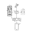
図1は、本開示の態様に従った、USB(ユニバーサルシリアルバス)ドアベルドングル13の実施形態を含むシステムを例示する機能ブロック図である。USBドアベルドングル13は、USBポートに適合するように設計された電子ハードウェアデバイスであってもよい。図1に示されるように、USBドアベルドングル13は、マイクロコントローラ4、フラッシュメモリ6、スピーカ1、LEDライト7、及び通信モジュール8を含む。USBドアベルドングル13の内部の各々の構成要素は、個々の機能を実行し、個々の機能は次いで、システム全体の効率的な働きに貢献する。USBドアベルドングル13は、ドアベル12と直接又は間接的に通信してもよい。ドアベル12は、無線データ伝送の能力を有するドアベルであってもよい。ドアベル12は、マイクロフォン、スピーカ、カメラ、及び/又はボタンを備えてもよい。ドアベル12は、インターホンシステムとしての機能を果たしてもよく、インターホンシステムは次いで、USBドアベルドングル13及び/又はスマートデバイス18にデジタル音声及び/又はビデオを中継し、ユーザ及び訪問者が相互にリモートに通信することを可能にする。
FIG. 1 is a functional block diagram illustrating a system including an embodiment of a USB (universal serial bus)
スマートデバイス18は、インターネットを介してデータを受信及び伝送する能力を有し、音声及びビデオ通信を伝送及び受信する能力を有し、或る程度自律的に動作することができる任意の電子デバイスであってもよい。スマートデバイス18の例は、スマートフォン、タブレット、ラップトップ、コンピュータ、及びVOIP電話システムを含むが、それらに限定されない。1つの非限定的な態様では、スマートデバイス18は、ドアベル12がUSBドアベルドングル13に接続する前の、ドアベル12における訪問者(図示せず)とユーザ(図示せず)との間の内部接点であってもよい。この態様では、ユーザがスマートデバイス18を介してドアベル12に接続することができない場合、サーバ17によって経路指定されたデータは、USBドアベルドングル13に案内されてもよい。
The
1つの態様では、USBドアベルドングル13、スマートデバイス18、及びドアベル12は、Wi−Fiを介して通信する。この態様では、通信モジュール8は、GainspanによるGS2011Mモジュールなど、市販の構成要素であってもよく、又はそれは、マイクロコントローラ及びシリアルホストインタフェースによりデバイスに低電力、高速Wi−Fi、及びインターネット接続性を追加する別のモジュールであってもよい。更に、図1を参照すると、通信モジュール8は、ネットワーク16を介してサーバ17に、サウンド及びUSBドアベルドングル13に関連する識別情報などのデータを含むアウトバウンドデータ呼び出しを送信してもよい。ネットワーク16は、コンピュータが物理的又は仮想的のいずれかでデータを交換することを可能にする電気通信ネットワークであってもよい。サーバ17は、送信された識別情報を使用してどのUSBドアベルドングル13がドアベル12と関連付けられるかを判定し、サーバ17を通じてUSBドアベルドングル13に、伝送された信号を経路指定する。サーバ17は、経路指定などのネットワークサービスを提供し、又は提供することを支援するために、コンピュータネットワークにわたって要求に応答するシステムであってもよい。ドアベル12は、USBドアベルドングル13と通信するために、通信モジュール8を介してネットワーク16に接続してもよい。
In one embodiment, the
Bluetooth(登録商標)又はZigBee(登録商標)(IEEE802.15.4)などの他のデータ伝送プロトコルは、モバイルデバイス又は無線データ伝送を受信する能力を有する任意の他のデバイスにデータを伝送するために、通信モジュール8に組み込まれてもよい。この態様では、データは、ドアベル12へのUSBドアベルドングル13の近接性に応じて、通信モジュール8を介してBluetooth(登録商標)プロトコルを通じて、マイクロコントローラ4に直接伝送されてもよい。
Other data transmission protocols such as Bluetooth® or ZigBee® (IEEE802.5.4) are for transmitting data to mobile devices or any other device capable of receiving wireless data transmission. May be incorporated into the communication module 8. In this aspect, the data may be transmitted directly to the
無線接続が行われると、マイクロコントローラ4は、ドアベル12からUSBドアベルドングル13に配信されたデータを処理することができる。マイクロコントローラ4は、デバイスに入り、デバイスから出るコマンドを取り扱い及び分配し、適切な構成要素にそれらを経路指定するUSBドアベルドングル13に組み込まれた内蔵処理システムであってもよい。ドアベル12のボタンが訪問者によって押下される場合、マイクロコントローラ4は、USBドアベルドングル13を介してユーザに、LEDライト7を活性化すること、及び/又はスピーカ1を通じて音声着信音を発することなどの通知信号を伝送してもよい。USBドアベルドングル13は、1つ以上の入力ボタン3を備えてもよい。ユーザによって押下されるとき、入力ボタン3は、ユーザが音声伝送を通じて訪問者と通信することを可能にするようにマイクロフォン9を活性化してもよい。
When the wireless connection is made, the
図1を更に参照すると、USBコネクタ5は、コンピュータ10(図4A)及び/又はUSBウォールアダプタ11(図4B)からデータ及び/又は電流を伝送してもよい。電流は、電力レギュレータ2に伝送され、電力レギュレータ2は次いで、USBドアベルドングル13内の全ての構成要素に電力を分配する。USBコネクタ5を介してコンピュータ10から伝送された任意のデータは、フラッシュメモリ6に記憶されてもよい。本開示の1つの態様では、ユーザは、ドアベル12のボタンが押下されるときに発することができる音声着信音をフラッシュメモリ6に記憶してもよい。
Further referring to FIG. 1, the
図2は、本開示の態様に従った、USBドアベルドングル13の断面図を示す。USBドアベルドングル13は、スピーカ1、電力レギュレータ2、入力ボタン3、マイクロコントローラ4、USBコネクタ5、LEDライト7、通信モジュール8、及びマイクロフォン9と連動するフラッシュメモリ6を含んでもよい。USBドアベルドングル13の内部に組み込まれたフラッシュメモリ6は、1つのデバイスからコンピュータ10などの別のデバイスにユーザのデータを記憶又は転送するために使用されてもよい。フラッシュメモリ6はまた、ユーザがドアベル12についての音声通知として選択することができる潜在的な着信音を記憶するために使用されてもよい。通信モジュール8は、Bluetooth(登録商標)及び/又はWi−Fi(登録商標)能力を含んでもよく、任意の所与の時に利用可能な無線接続に応じてドアベル12に接続してもよい。本開示の1つの態様では、USBドアベルドングル13は、ネットワーク16内で利用可能な近隣デバイス(複数可)に、利用可能なWi−Fi(登録商標)信号を拡張する能力を有することができる。この態様では、USBドアベルドングル13は、ネットワーク16から伝送された無線信号を受信し、無線信号を増幅し、次いで、ユーザの位置又は設備全体を通じて増大した信号を伝送する能力を有する構成要素(例えば、Wi−Fi(登録商標)ルータにおいて見出される)を含んでもよい。USBドアベルドングル13は、電力がデバイスに対して利用可能でないときに動作を可能にするバッテリ(図示せず)を含んでもよい。
FIG. 2 shows a cross-sectional view of the USB
図3は、本開示の態様に従った、USBドアベルドングル13の前面斜視図である。USBドアベルドングル13の上面は、音声がスピーカ1から発することを可能にする穿孔パターンを特徴付けることができる。LEDライト7が光を発することを可能にする開口部は、USBドアベルドングル13の前向き面上に位置してもよい。USBドアベルドングル13内に取り付けられたLEDライト7は、ドアベル12から伝送された信号に応じて継続的にターンオン及びターンオフし、又は点滅してもよい。LEDライト7はまた、USBドアベルドングル13がコンピュータ10又はUSBウォールアダプタ11に差し込まれる場合に照らされてもよい。この態様では、LEDライト7の照明は、充電又はデータ転送を示してもよく、ユーザがコンピュータ10又はUSBウォールアダプタ11からUSBドアベルドングル13を抜くとターンオフしてもよい。
FIG. 3 is a front perspective view of the USB
入力ボタン3は、USBドアベルドングル13の前向き面上に位置付けられてもよい。USBドアベルドングル13がドアベル12から信号を受信すると、マイクロコントローラ4は、スピーカ1から音声を発し、及び/又はLEDライト7を照らすことによって、ユーザに通知するようにトリガされてもよい。ユーザは、USBドアベルドングル13からドアベル12にデジタル音声を伝送するために、マイクロフォン9を活性化するように入力ボタン3を押下してもよい。
The
図4Aは、本開示の態様に従った、USBドアベルドングル13及びコンピュータ10の前面斜視図である。USBドアベルドングル13は、USBドアベルドングル13をコンピュータ10のUSBポートに差し込むことができるので、コンピュータ10から電力を抽出することができる。USBドアベルドングル13をコンピュータ10に挿入することができるので、ユーザはまた、コンピュータ10からデータを抽出することができ、USBドアベルドングル13に組み込まれたフラッシュメモリ6にデータを記憶することができ、並びに/又はユーザは、コンピュータ10とUSBドアベルドングル13との間で後方及び前方にデータを転送することが可能であってもよい。
FIG. 4A is a front perspective view of the USB
図4Bは、本開示の態様に従った、USBドアベルドングル13及びUSBウォールアダプタ11の前面斜視図である。USBドアベルドングル13は、USBウォールアダプタ11から電力を抽出するために、USBウォールアダプタ11のUSBポートに差し込まれてもよく、USBウォールアダプタ11は、ウォールコンセントに差し込まれてもよい。USBドアベルドングル13は、USBポートを供給し、また、USBドアベルドングル13に電力を提供する任意のデバイスに挿入されてもよい。
FIG. 4B is a front perspective view of the USB
図5は、Wi−Fi(登録商標)ドアベル12と通信するUSBドアベルドングル13を含むシステムを例示する機能ブロック図である。本開示の1つの態様では、通知コマンドがWi−Fi又はBluetooth(登録商標)を通じてドアベル12からUSBドアベルドングル13に伝送されるとき、ユーザは、USBドアベルドングル13に組み込まれたマイクロフォン9を通じて訪問者に話しかける能力を有することができる。
FIG. 5 is a functional block diagram illustrating a system including a
1つの態様では、USBドアベルドングル13は、Wi−Fi(登録商標)を介してドアベル12と通信してもよい。通信モジュール8は、ネットワーク16内に位置するサーバ17に、サウンド及びUSBドアベルドングル13に関連する識別情報などのデータを含むアウトバウンドデータ呼び出しを送信してもよい。サーバ17は次いで、ドアベル12から配信された識別情報を使用して、どのUSBドアベルドングル13がドアベル12と関連付けられるかを判定してもよく、ネットワーク16を通じてUSBドアベルドングル13に、伝送された信号を経路指定してもよい。上記言及されたように、接続はまた、ドアベル12へのその近接性に応じて、USBドアベルドングル13の通信モジュール8に組み込まれたBluetooth(登録商標)モジュールを介して、Bluetooth(登録商標)プロトコルを通じて伝送してもよい。
In one embodiment, the
図6は、本開示の態様に従った、USBドアベルドングル13と関連付けられた例示的な使用及び機能を例示する処理フローチャートである。訪問者は、ブロックB30において、ドアベル12上に位置するボタンを押下してもよい。ブロックB32において、ドアベル12は、ネットワーク16に、ビデオ、音声、及びドアベル12に関連付けられた識別情報などのデータを伝送する。サーバ17は、どのスマートデバイス18、ウェブベースアプリケーション、USBドアベルドングル13、及び/又は他のデバイスをドアベル12と関連付けられることができるかを識別する。サーバ17は、各々のデバイスの機能に基づいて適切なデバイスに、音声及び/又はビデオデータなどの適切なデータを経路指定してもよい。ユーザは最初に、スマートデバイス18又はドアベル12と関連付けられた別のデバイス上で通知を受信してもよい。要求が承認される場合(ブロックB32においてYes)、ユーザ及び訪問者は、ブロックB34において、ドアベル12に及びドアベル12から送信された音声及びビデオ伝送を介して通信してもよい。伝送は次いで、ユーザが切断又はハングアップすると、ブロックB36において終端されてもよい。
FIG. 6 is a processing flow chart illustrating exemplary uses and functions associated with the USB
スマートデバイス18との接続を行うことができない場合(ブロックB32においてNo)、サーバ17は、ブロックB38において、音声チャイムを発するためにUSBドアベルドングル13にデータを経路指定する。それに限定されないが、不良なネットワーク接続、スマートデバイス18がネットワークに接続されていないこと、及び/又はスマートデバイス18が電力をオフにされていることなどの理由は、ユーザに音声チャイムを発するようにUSBドアベルドングル13をトリガすることがある。
If the connection with the
ユーザがUSBドアベルドングル13の前にあり、要求に応える能力を有する場合(ブロックB40においてYes)、ユーザは、ブロックB42において、USBドアベルドングル13上に位置する入力ボタン3を押下してもよい。ブロックB42においてUSBドアベルドングル13上に位置する入力ボタン3を押下することは、ネットワーク16を介したドアベル12とUSBドアベルドングル13との間の接続を生じさせる。ユーザ及び訪問者は、ブロックB44において、ドアベル12及びUSBドアベルドングル13に、並びにドアベル12及びUSBドアベルドングル13から送信された音声伝送を介して通信してもよい。伝送は次いで、ユーザが入力ボタン3を押下することによって切断するとき、ブロックB36において終端されてもよい。
If the user is in front of the USB
ユーザがUSBドアベルドングル13の前になく、又はUSBドアベルドングル13がネットワーク16から切断され、若しくは電力をオフにされているかのいずれかの場合(ブロックB40においてNo)、伝送は次いで、ブロックB36において終端されてもよい。図6に関して上記説明されたステップは、上記説明されたのとは異なる順序で行われてもよい。例えば、サーバ17は、スマートデバイス18にデータを経路指定する前に、USBドアベルドングル13にデータを経路指定してもよい。
If the user is not in front of the USB
図7は、本開示の態様に従った、無線スピーカデバイスを含むシステムを例示する機能ブロック図である。Wi−Fi(登録商標)は、本開示の態様に従った無線データ交換の1つの方法である。図7のシステム内のデバイスは、ユーザのネットワーク65に接続してもよい。ユーザのネットワーク65は、無線ネットワーク内で発声及びデータエンドポイントを接続するローカルエリアネットワーク(LAN)、インターネットエリアネットワーク(IAN)、又はワイドエリアネットワーク(WAN)であってもよい。システム内の1つのデバイスは、ユーザのネットワーク65に接続されると(3G、4G、LTEなどを備えていない限り)、デバイスは次いで、システムネットワーク52にデータを送信することによって通信してもよい。システムネットワーク52は、Wi−Fi(登録商標)対応デバイスへの及びWi−Fi(登録商標)対応デバイスからのデータの転送を可能にする無線電気通信ネットワークである。サーバ53は、システムネットワーク52に組み込まれてもよく、又はシステムネットワーク52に結合されてもよい。サーバ53は、命令及びユーザ優先度に従ってデータを経路指定することなどのネットワークサービスを提供し、又はネットワークサービスを提供することを支援するために、コンピュータネットワークにわたって要求に応答するシステムである。システム内のデバイスは、システムネットワーク52にデータを送信し、システムネットワーク52では、サーバ53がデータを処理し、適切なデバイスにデータを経路指定する。例えば、識別情報、デジタル音声、処理された視覚、及び/又はデバイス診断など、無線通信ドアベル61からのデータは、システムネットワーク52に送信されてもよい。サーバ53は、無線通信ドアベル61から送信されたデータを処理し、それに従ってシステム内の他のデバイスにそれを経路指定する。例えば、サーバ53は、無線通信ドアベル61から送信された診断データを処理してもよく、サーバ53は、無線通信ドアベル61のバッテリが切れかかっている場合(例えば、残っているバッテリが10%)、スマートデバイス54を介してユーザに通知するために診断データを経路指定する。 FIG. 7 is a functional block diagram illustrating a system including a wireless speaker device according to aspects of the present disclosure. Wi-Fi® is a method of wireless data exchange according to aspects of the present disclosure. The devices in the system of FIG. 7 may be connected to the user's network 65. The user's network 65 may be a local area network (LAN), an internet area network (IAN), or a wide area network (WAN) that connects vocal and data endpoints within the wireless network. Once a device in the system is connected to the user's network 65 (unless it has 3G, 4G, LTE, etc.), the device may then communicate by transmitting data to the system network 52. .. The system network 52 is a wireless telecommunications network that enables the transfer of data to and from Wi-Fi® compatible devices. The server 53 may be incorporated into the system network 52 or may be coupled to the system network 52. The server 53 is a system that responds to requests across a computer network to provide network services such as routing data according to instructions and user priorities, or to assist in providing network services. Devices in the system send data to the system network 52, where the server 53 processes the data and routes the data to the appropriate device. Data from the wireless communication doorbell 61, such as identification information, digital audio, processed vision, and / or device diagnostics, may be transmitted to the system network 52. The server 53 processes the data transmitted from the wireless communication doorbell 61 and routes it to other devices in the system accordingly. For example, the server 53 may process the diagnostic data transmitted from the wireless communication doorbell 61, and the server 53 may have the wireless communication doorbell 61 running out of battery (eg, 10% of the remaining battery). , Route diagnostic data to notify the user via the smart device 54.
本開示の1つの態様では、図7において説明されるシステム内で通信する全てのデバイスは、Bluetooth(登録商標)などの他の無線通信プロトコルを使用してもよい。Bluetooth(登録商標)は、相互に近接近したデバイスの間で短距離にわたってデータを交換するための無線技術標準である。Bluetooth(登録商標)無線伝送は、近接近していることを理由にシステムネットワーク52又はサーバ53の使用を必要とせず、識別情報、デジタル音声、処理された視覚、及び/又はデバイス診断などのデータを転送する能力を維持する。 In one aspect of the disclosure, all devices communicating within the system described in FIG. 7 may use other wireless communication protocols such as Bluetooth®. Bluetooth® is a wireless technology standard for exchanging data over short distances between devices that are in close proximity to each other. Bluetooth® wireless transmission does not require the use of system network 52 or server 53 because of its close proximity, and data such as identification information, digital audio, processed vision, and / or device diagnostics. Maintain the ability to transfer.
本開示の1つの方法及びシステムでは、無線通信ドアベル61内の全てのハードウェア構成要素は、無線通信ドアベル61のボタン55が訪問者によって押下されるまで、ハイバネーションの状態にあってもよい。この態様では、通信モジュール及び/又はカメラなど、バッテリから電力を引き出す全ての構成要素は、使用中でないときはバッテリ電力を消耗しない。ボタン55が押下されるとき、それは、全ての構成要素を活性化してもよく、スマートデバイス54へのデータのストリーミングが中断するとき、全ての構成要素は、ハイバネーションモードに戻ってもよい。 In one method and system of the present disclosure, all hardware components within the wireless communication doorbell 61 may be in a hibernation state until the button 55 of the wireless communication doorbell 61 is pressed by the visitor. In this aspect, all components that draw power from the battery, such as communication modules and / or cameras, do not consume battery power when not in use. When the button 55 is pressed, it may activate all components, and when streaming data to the smart device 54 is interrupted, all components may return to hibernation mode.
本開示の1つの態様では、バッテリ寿命及びインターネット接続性など、無線通信ドアベル61と関連付けられた診断データは、通信モジュールがハイバネーションモードから起動するときにシステムネットワーク52に中継されてもよい。無線通信ドアベル61によって提供された診断データにより、サーバ53は、スマートデバイス54に通知を送信してもよく、バッテリを充電すること、又は無線通信ドアベル61へのインターネットの接続性をリセットすることをユーザに通知する。 In one aspect of the disclosure, diagnostic data associated with the wireless communication doorbell 61, such as battery life and internet connectivity, may be relayed to the system network 52 when the communication module boots from hibernation mode. With the diagnostic data provided by the wireless communication doorbell 61, the server 53 may send a notification to the smart device 54 to charge the battery or reset the internet connectivity to the wireless communication doorbell 61. Notify the user.
図7に示され、図8に関して以下で更に詳細に説明されるように、無線通信ドアベル61は、第三者ハードウェア58及び/又は第三者ドアベルチャイム59と通信してもよい。第三者ドアベルチャイム59は、無線通信ドアベル61のボタン55が押下されるとき、ユーザに、他の機能の中で音声チャイム又はメッセージを発することができるスタンドアロン製品又は構成要素であってもよい。無線通信ドアベル61は、第三者ドアベルチャイム59と関連付けられた伝送能力に応じて、第三者ドアベルチャイム59と直接又は間接的に通信してもよい。1つの態様では、通信モジュールと組み込まれる場合、第三者ドアベルチャイム59は、システムネットワーク52を介して無線通信ドアベル61と通信してもよい。この態様では、第三者ドアベルチャイム59は、無線通信ドアベル61とともに、ユーザのネットワーク65に接続されてもよい。本開示の1つの態様では、第三者ドアベルチャイム59は、通信モジュール(例えば、Wi−Fi若しくはBluetooth(登録商標))8、スピーカ1、及び/又はマイクロフォン9を含むUSBドングル13(図1)の形式をとってもよい。この態様では、USBドングル13は、コンピュータ10(図4A)又はUSBアダプタ11(図4B)に差し込まれることによって電力を引き出してもよい。Wi−Fi(登録商標)を通じて接続される場合、デジタル音声及び/又は識別情報など、無線通信ドアベル61から送信されたデータは、システムネットワーク52を通じてUSBドングル13に経路指定されてもよい。Bluetooth(登録商標)プロトコルを使用して接続される場合、無線通信ドアベル61は、USBドングル13に直接、デジタル音声などのデータを配信してもよい。USBドングル13は、USBドングル13内に設置されたLEDライト7(図1)及び/又はスピーカ1から引き出された視覚及び/又は音声キューを使用して、ドアにおける或るユーザを警告してもよい。ユーザは次いで、USBドングル13上に設置されたマイクロフォン9を通じて訪問者と通信することが可能であってもよい。本開示の1つの態様では、USBドングル13は、ユーザのネットワーク65により多くのアクセス又はより良好なアクセスを提供するためのWi−Fi(登録商標)エキステンダ、リピータ、又はブースタとしての機能を果たしてもよい。この態様では、USBドングル13は、ユーザのネットワーク65から伝送された無線信号を受信し、無線信号を増幅し、次いで、ユーザの位置又は設備全体を通じて増大した信号を伝送する能力を有する構成要素を含んでもよい。
As shown in FIG. 7 and described in more detail below with respect to FIG. 8, the wireless communication doorbell 61 may communicate with
図8は、本開示の態様に従った、無線スピーカデバイスの実施形態に関連する処理フローチャートである。この態様では、第三者ドアベルチャイム59(図7)は、通信モジュール、入力ボタン、スピーカ、及びマイクロフォンを含んでもよい。訪問者は、ブロックB70において、無線通信ドアベル61の前面上に位置するボタン55を押下し、システムネットワーク52に無線でデータを伝送するように無線通信ドアベル61をトリガしてもよい。 FIG. 8 is a processing flowchart related to the embodiment of the wireless speaker device according to the aspect of the present disclosure. In this aspect, the third party doorbell chime 59 (FIG. 7) may include a communication module, an input button, a speaker, and a microphone. In block B70, the visitor may press a button 55 located on the front surface of the wireless communication doorbell 61 to trigger the wireless communication doorbell 61 to wirelessly transmit data to the system network 52.
ブロックB72において、無線通信ドアベル61は、システムネットワーク52に、音声、ビデオ、及び/又は無線通信ドアベル61に関連付けられた識別情報などのデータを伝送する。サーバ53は、どのスマートデバイス54、ウェブベースアプリケーション、第三者ドアベルチャイム59、及び/又は他のデバイスを無線通信ドアベル61と関連付けることができるかを識別する。サーバ53は、各々のデバイスの機能に基づいて、適用可能なデバイスに、音声又はビデオデータなどの適切なデータを経路指定してもよい。ユーザは、スマートデバイス54又は無線通信ドアベル61と関連付けられた別のデバイス上で、承認/拒否プロンプトを受信してもよい。要求が承認される場合(ブロックB72においてYes)、ユーザ及び訪問者は、ブロックB74において、無線通信ドアベル61に及び無線通信ドアベル61から送信された音声及びビデオ伝送を介して通信してもよい。伝送は次いで、ユーザが切断又はハングアップすると、ブロックB76において終端されてもよい。 At block B72, the wireless communication doorbell 61 transmits data such as voice, video, and / or identification information associated with the wireless communication doorbell 61 to the system network 52. The server 53 identifies which smart device 54, web-based application, third party doorbell chime 59, and / or other device can be associated with the wireless communication doorbell 61. The server 53 may route appropriate data, such as audio or video data, to applicable devices based on the functionality of each device. The user may receive an approval / rejection prompt on the smart device 54 or another device associated with the wireless communication doorbell 61. If the request is approved (Yes in block B72), users and visitors may communicate in block B74 via audio and video transmissions transmitted to and from the wireless communication doorbell 61. The transmission may then be terminated at block B76 when the user disconnects or hangs.
スマートデバイス54との接続を行うことができない場合(ブロックB72においてNo)、サーバ53は、ブロックB78において、音声チャイムを発するために第三者ドアベルドングル59にデータを経路指定する。それに限定されないが、不良な無線ネットワーク接続、スマートデバイス54がユーザのネットワーク65に接続されていないこと、スマートデバイス54が電力をオフにされていること、又は承認/拒否プロンプトが棄却若しくは無視されていることなどの理由は、ユーザに音声トーンを発するように第三者ドアベルチャイム59をトリガすることがある。 If the connection with the smart device 54 cannot be made (No in block B72), the server 53 routes data to a third party door bell dongle 59 in block B78 to emit a voice chime. Poor wireless network connection, not limited to that, the smart device 54 is not connected to the user's network 65, the smart device 54 is powered off, or the approval / rejection prompt is rejected or ignored. For reasons such as being present, the third party doorbell chime 59 may be triggered to emit a voice tone to the user.
ユーザが第三者ドアベルチャイム59の前にあり、要求に応える能力を有する場合(ブロックB80においてYes)、ユーザは、ブロックB82において、第三者ドアベルチャイム59上に位置する入力ボタンを押下してもよい。第三者ドアベルチャイム59上に位置する入力ボタンを押下することは、システムネットワーク52を介した無線通信ドアベル61と第三者ドアベルチャイム59との間の接続を生じさせる。ユーザ及び訪問者は、ブロックB82において、無線通信ドアベル61と第三者ドアベルチャイム59との間で送信された音声伝送を介して通信してもよい。伝送は次いで、ユーザが入力ボタンを押下することによって切断するとき、ブロックB76において終端されてもよい。 If the user is in front of the third party doorbell chime 59 and has the ability to respond to the request (Yes in block B80), the user presses an input button located on the third party doorbell chime 59 in block B82. May be good. Pressing the input button located on the third party doorbell chime 59 creates a connection between the wireless communication doorbell 61 and the third party doorbell chime 59 via the system network 52. The user and the visitor may communicate in block B82 via voice transmission transmitted between the wireless communication doorbell 61 and the third party doorbell chime 59. The transmission may then be terminated at block B76 when the user disconnects by pressing an input button.
ユーザが第三者ドアベルチャイム59の前になく、又は第三者ドアベルチャイム59がユーザのネットワーク65から切断され、若しくは電力をオフにされているかのいずれかの場合(ブロックB80においてNo)、伝送は次いで、ブロックB84において終端されてもよい。図8に関して上記説明されたステップは、上記説明されたのとは異なる順序で行われてもよい。例えば、サーバ53は、スマートデバイス54にデータを経路指定する前に、第三者ドアベルチャイム59にデータを経路指定してもよい。 Transmission if the user is not in front of the third party doorbell chime 59, or if the third party doorbell chime 59 is disconnected from the user's network 65 or powered off (No in block B80). May then be terminated at block B84. The steps described above with respect to FIG. 8 may be performed in a different order than described above. For example, the server 53 may route the data to the third party doorbell chime 59 before routing the data to the smart device 54.
図9を参照すると、本実施形態は、ドアベル100などの音声/ビデオ(A/V)記録及び通信デバイスを含む。本開示がA/V記録及び通信ドアベルを含む方法及びシステムの多数の例を提供するが、本実施形態は、ドアベル以外のA/V記録及び通信デバイスに対して等しく適用可能である。例えば、本実施形態は、1つ以上のA/V記録及び通信ドアベルに代えて、又はそれに加えて、1つ以上のA/V記録及び通信セキュリティカメラを含んでもよい。例示的なA/V記録及び通信セキュリティカメラは、前方ボタン及び関連する構成要素を有さないが、本明細書で説明されるドアベルの構造及び機能性の全てを実質的に含んでもよい。
Referring to FIG. 9, the present embodiment includes an audio / video (A / V) recording and communication device such as a
無線A/V記録及び通信ドアベル100は典型的には、住居設備、ビジネス、保管設備など、構造(図示せず)への入口の近くに位置する。無線A/V記録及び通信ドアベル100は、カメラ102、マイクロフォン104、及びスピーカ106を含む。カメラ102は、例えば、720p又はそれよりも良好な画像表示解像度においてビデオ画像を捕捉する能力を有するものなど、高解像度(HD)ビデオカメラを含んでもよい。図示されないが、無線A/V記録及び通信ドアベル100はまた、筐体、1つ以上の動きセンサ(及び/又は、他のタイプのセンサ)、ボタンなど、他のハードウェア及び/又は構成要素を含んでもよい。無線A/V記録及び通信ドアベル100は更に、その両方が完全に示されるようにそれらの全体を参照することによって以下に組み込まれる、米国特許出願公開第2015/0022620号(出願番号第14/499,828号)及び第2015/0022618号(出願番号第14/334,922号)において説明された無線通信ドアベルと同様の構成部品及び/又は機能性を含んでもよい。
The wireless A / V recording and
図9を更に参照すると、無線A/V記録及び通信ドアベル100は、ユーザの無線ネットワーク110と通信し、ユーザの無線ネットワーク110は、例えば、IEEE802.11標準及び/又は他の無線通信標準(複数可)と互換性を有するWi−Fiネットワークなどのローカルエリアネットワーク(LAN)であってもよい。ユーザの無線ネットワーク110は、別のネットワーク112に接続され、別のネットワーク112は、例えば、インターネット及び/又は公衆交換電話網(PSTN)を含んでもよい。以下で説明されるように、無線A/V記録及び通信ドアベル100は、無線ネットワーク110及びネットワーク112を介して、ユーザのクライアントデバイス114と通信してもよい。ユーザのクライアントデバイス114は、例えば、スマートフォン、携帯情報端末(PDA)、又は別の通信デバイスなど、携帯電話(セルラ電話とも称されてもよい)を含んでもよい。ユーザのクライアントデバイス114は、ストリーミング及び/又は記録されたビデオ画像を表示する能力を有するディスプレイ(図示せず)及び関連する構成要素を含む。ユーザのクライアントデバイス114はまた、ストリーミング及び/又は記録された音声をブロードキャストする能力を有するスピーカ及び関連する構成要素を含んでもよく、また、マイクロフォンを含んでもよい。無線A/V記録及び通信ドアベル100はまた、無線ネットワーク110及びネットワーク112を介して、1つ以上のリモート記憶装置(複数可)116(「クラウド記憶装置(複数可)」と交換可能に称されてもよい)及び/又は1つ以上のサーバ118と通信してもよい。図9はネットワーク112とは別個の構成要素として記憶装置116及びサーバ118を例示するが、記憶装置116及び/又はサーバ118は、ネットワーク112の構成要素であると見なされてもよいことが理解されよう。
Further referring to FIG. 9, the wireless A / V recording and
ネットワーク112は、図9に示されるように、上記言及されたモジュール、デバイス、及びシステムに動作可能に結合するように構成された、任意の無線ネットワーク若しくは任意の有線ネットワーク、又はそれらの組み合わせであってもよい。例えば、ネットワーク112は、PSTN(公衆交換電話網)、インターネット、ローカルイントラネット、PAN(パーソナルエリアネットワーク)、LAN(ローカルエリアネットワーク)、WAN(ワイドエリアネットワーク)、MAN(メトロポリタンエリアネットワーク)、仮想プライベートネットワーク(VPN)、ストレージエリアネットワーク(SAN)、フレームリレー接続、アドバンストインテリジェントネットワーク(AIN)接続、同期光ネットワーク(SONET)接続、デジタルT1、T3、E1若しくはE3ライン、デジタルデータサービス(DDS)接続、DSL(デジタル加入者ライン)接続、イーサネット(登録商標)接続、ISDN(統合サービスデジタルネットワーク)ライン、V.90、V.34、若しくはV.34bisアナログモデム接続などのダイヤルアップポート、ケーブルモデム、ATM(非同期転送モード)接続、又はFDDI(ファイバ分散データインタフェース)若しくはCDDI(コパー分散データインタフェース)接続のうちの1つ以上を含んでもよい。更に、通信はまた、WAP(無線アプリケーションプロトコル)、GPRS(汎用パケット無線サービス)、GSM(グローバルシステムフォーモバイルコミュニケーション)、CDMA(符号分割多元接続)、TDMA(時分割多元接続)、FDMA(周波数分割多元接続)、及び/若しくはOFDMA(直交周波数分割多元接続)、セルラ電話ネットワーク、GPS、CDPD(セルラデジタルパケットデータ)、RIM(リサーチインモーションリミテッド)多重ネットワーク、Bluetooth(登録商標)無線、又はIEEE802.11ベースの無線周波数ネットワークを含む、様々な無線ネットワークのいずれかへのリンクを含んでもよい。ネットワークは更に、RS−232シリアル接続、IEEE−1394(Firewire)接続、ファイバチャネル接続、IrDA(赤外線)ポート、SCSI(スモールコンピュータシステムインタフェース)接続、USB(ユニバーサルシリアルバス)接続、又は他の有線若しくは無線、デジタル若しくはアナログ、インタフェース若しくは接続、メッシュ若しくはDigi(登録商標)ネットワーキングのうちのいずれか1つ以上を含むことができ、又はそれらのうちのいずれか1つ以上とインタフェース接続することができる。1つの例示的な実施形態では、ネットワーク112は、LANを含むユーザの無線ネットワーク110に接続されたWANを含む。
The
本実施形態の1つ以上の態様に従って、人間(「訪問者」と交換可能に称されてもよい)が無線A/V記録及び通信ドアベル100に到達するとき、無線A/V記録及び通信ドアベル100は、訪問者の存在を検出し、カメラ102の視野内のビデオ画像を捕捉することを開始する。無線A/V記録及び通信ドアベル100はまた、マイクロフォン104を通じて音声を捕捉してもよい。無線A/V記録及び通信ドアベル100は、動きセンサを使用して、並びに/又は訪問者が無線A/V記録及び通信ドアベル100上のボタンを押圧したことを検出することによって、訪問者の存在を検出してもよい。
According to one or more aspects of this embodiment, when a human being (which may be interchangeably referred to as a "visitor") reaches the wireless A / V recording and
訪問者の検出に応答して、無線A/V記録及び通信ドアベル100は、ユーザの無線ネットワーク110及びネットワーク112を介して、ユーザのクライアントデバイス114(図9)に警告を送信する。無線A/V記録及び通信ドアベル100はまた、ユーザのクライアントデバイス114に、ストリーミングビデオを送信し、また、ストリーミング音声を送信してもよい。ユーザが警告に応える場合、双方向音声通信は次いで、無線A/V記録及び通信ドアベル100並びにユーザのクライアントデバイス114を通じて、訪問者とユーザとの間で行われてもよい。ユーザは、呼び出しの期間の全体を通じて訪問者を見ることができるが、訪問者はユーザを見ることができない(無線A/V記録及び通信ドアベル100が、それが一部の実施形態にあることができるディスプレイを含まない限り)。
In response to the visitor's detection, the wireless A / V recording and
無線A/V記録及び通信ドアベル100のカメラ102によって捕捉されたビデオ画像(並びに、マイクロフォン104によって捕捉された音声)は、クラウドにアップロードされてもよく、リモート記憶装置116(図9)に記録されてもよい。一部の実施形態では、ビデオ及び/又は音声は、ユーザが自身のクライアントデバイス114に送信された警告を無視すると選択した場合でさえ、リモート記憶装置116に記録されてもよい。
Radio A / V recording and communication The video image captured by the
図10〜12は、本実施形態の態様に従った、無線音声/ビデオ(A/V)通信ドアベル130を例示する。図10は、取り付けブラケット137と結合されたドアベル130の正面図であり、図11は、取り付けブラケット137と結合されたドアベル130の背面図であり、図12は、取り付けブラケット137と結合されたドアベル130の左側面図である。ドアベル130は、背面板139(図11)に取り付けられた面板135を含む。図12を参照すると、面板135は、実質的に平面な外形を有する。面板135は、それに限定されないが、艶消アルミニウム若しくはステンレス鋼、金属合金、又はプラスチックなどの金属を含む任意の適切な材料を含んでもよい。面板135は、ドアベル130の内在物を保護し、ドアベル130の外側前面としての機能を果たす。
10 to 12 illustrate a wireless voice / video (A / V)
図10を参照すると、面板135は、ボタン133及びライトパイプ136を含む。ボタン133及びライトパイプ136は、面板135の外形に一致してもよく、又は一致しなくてもよい様々な外形を有してもよい。ライトパイプ136は、それに限定されないが、ドアベル130内で生じる光が通過することを可能にする能力を有する、透過プラスチックを含む任意の適切な材料を含んでもよい。光は、以下で更に説明されるように、ドアベル130内に含まれる発光ダイオード(LED)などの1つ以上の発光素子によって生じてもよい。ボタン133は、ボタン133が訪問者によって押下されるとき、ドアベル130内に位置するボタンアクチュエータ(図示せず)と接触してもよい。押下されるとき、ボタン133は、以下で更に説明されるように、ドアベル130の1つ以上の機能をトリガすることができる。
Referring to FIG. 10, the
図10及び12を参照すると、ドアベル130は更に、面板135にかみ合う筐体131を含む。例示される実施形態では、筐体131は、面板135の上縁135T(図10)に隣接するが、代替的な実施形態では、筐体131と面板135との間の1つ以上の隙間は、ドアベル130を通じてサウンド及び/又は光の通過を促進することができる。筐体131は、任意の適切な材料を含んでもよいが、一部の実施形態では、筐体131の材料は好ましくは、赤外線光がドアベル130の内部から周囲、及びその逆に通過することを可能にする。ドアベル130は更に、レンズ132を含む。一部の実施形態では、レンズは、ドアベル130内に位置する1つ以上の赤外線センサに入り込む光を屈折させるようにパターン化することができる、Fresnelレンズを含んでもよい。ドアベル130は更に、以下で説明されるように、活性化されるときにビデオデータを捕捉するカメラ134を含む。
With reference to FIGS. 10 and 12, the doorbell 130 further includes a
図11は、本実施形態の態様に従った、ドアベル130の背面図である。例示されるように、筐体131は、ドアベル130の前方からその背面の周りに延在してもよく、背面板139の縁の周りにぴったりと適合することができる。背面板139は、それに限定されないが、艶消アルミニウム若しくはステンレス鋼、金属合金、又はプラスチックなどの金属を含む任意の適切な材料を含んでもよい。背面板139は、ドアベル130の内在物を保護し、ドアベル130の外側背面としての機能を果たす。面板135は、ドアベル130の前方から延在してもよく、背面板139の周りを少なくとも部分的に覆ってもよく、それによって、面板135と背面板139との間の結合された接続を可能にする。背面板139は、結合を容易にするためにその構造において窪みを有してもよい。
FIG. 11 is a rear view of the doorbell 130 according to the embodiment of the present embodiment. As illustrated, the
図11を更に参照すると、バネ接点140は、電源に接続された他の導電接点と係合されるとき、ドアベル130に電力を提供することができる。バネ接点140は、それに限定されないが、銅を含む任意の適切な導電材料を含んでもよく、内部への力、例えば、係合要素の挿入によって接触されるときに屈折する能力を有してもよい。ドアベル130は更に、マイクロUSB又は他のコネクタなどのコネクタ160を含み、それによって、電力及び/又はデータは、ドアベル130内の構成要素に及び構成要素から供給されてもよい。リセットボタン159は、背面板139上に位置してもよく、リセットボタン159が押下されるとき、ドアベル130内に位置するボタンアクチュエータ(図示せず)と接触してもよい。リセットボタン159が押下されるとき、それは、以下で説明されるように、1つ以上の機能をトリガすることができる。
Further referring to FIG. 11, the
図12は、本実施形態の態様に従った、取り付けブラケット137に結合されたドアベル130の左側外形図である。取り付けブラケット137は、住居又はオフィスなど、建物の外側などの表面にドアベル130を取り付けることを容易にする。図12に例示されるように、面板135は、上記説明されたように、ドアベル130の底部からカメラ134の直下まで延在してもよく、背面板139に接続してもよい。レンズ132は、ドアベル130の側面の周りで部分的に延在及び屈曲してもよい。筐体131は、上記説明されたように、ドアベル130の側面及び最上部の周りで延在及び屈曲してもよく、背面板139に結合されてもよい。カメラ134は、筐体131を通じてわずかに突出してもよく、それによって、より広い視野を与える。取り付けブラケット137は、背面板139と結合してもよく、その結果、それらは、接触の共通面内の様々なポイントにおいて相互に接触し、それによって、ドアベル130及び取り付けブラケット137を含むアセンブリを生成する。この段落において、及び他で説明される結合は、例えば、それに限定されないが、ネジ、締まりバネ、接着剤、又は他のファスナによって固定されてもよい。締まりバネは、異なる要素への接続を支持するための材料の物理強度と結合された圧力及び/又は重力に材料が依存するタイプの接続を指す。
FIG. 12 is a left side outline view of the doorbell 130 coupled to the mounting
図13は、取り付けブラケット137を有さないドアベル130の右側断面図である。例示される実施形態では、レンズ132は、筐体131の前面131Fと実質的に同一平面上にある。代替的な実施形態では、レンズ132は、筐体131内で埋め込まれてもよく、又は筐体131から外側に突出してもよい。カメラ134は、カメラプリント回路基板(PCB)147に結合され、カメラ134のレンズ134aは、筐体131内の開口を通じて突出する。カメラレンズ134aは、明確な画像を撮ることができるようにカメラ134に光の焦点を合わせる能力を有するレンズであってもよい。
FIG. 13 is a right sectional view of the doorbell 130 without the mounting
カメラPCB147は、ネジ、又は締まり接続、接着剤などの任意の適切なファスナによりドアベル内で固定されてもよい。カメラPCB147は、以下で説明されるように、ドアベル130のカメラ134の機能性を有効にする様々な構成要素を含む。赤外線LED168など、赤外線発光素子は、カメラPCB147に結合され、光センサが低レベルの周囲光を検出するときに活性化するようにトリガされてもよい。活性化されるとき、赤外線LED168は、筐体131及び/又はカメラ134を通じて、周囲環境に及び周囲環境から赤外線光を発することができる。赤外線光を検出するように構成することができるカメラ134は次いで、それがカメラ134の視野内の物体に反射するので、赤外線LED168によって発せられた光を捕捉することができ、その結果、ドアベル130は、夜間に画像を明確に捕捉することができる(「暗視」と称されてもよい)。
The
図13を続けて参照すると、ドアベル130は更に、前方PCB146を含み、前方PCB146は、例示される実施形態では、バッテリ166に隣接するドアベル130の下位部に存在する。前方PCB146は、ネジ、又は締まり接続、接着剤などの任意の適切なファスナによりドアベル130内で固定されてもよい。前方PCB146は、以下で更に説明されるように、音声及び照明構成要素の機能性を有効にする様々な構成要素を含む。バッテリ166は、ドアベル130の構成要素に電力を提供すると共に、バネ接点140から電力を受信することができ、それによって、電力消費及び供給のトリクル充電方法に従事する。代わりに、ドアベル130は、バネ接点140から電力を直接引き出すと共に、バネ接点140が全ての機能に必要な電力を提供しないときにのみバッテリ166に依存してもよい。
With reference to FIG. 13, the doorbell 130 further includes a
図13を続けて参照すると、ドアベル130は更に、電力PCB148を含み、電力PCB148は、例示される実施形態では、カメラPCB147の背後に存在する。電力PCB148は、ネジ、又は締まり接続、接着剤などの任意の適切なファスナによりドアベル130内で固定されてもよい。電力PCB148は、以下で更に説明されるように、電力及びデバイス制御構成要素の機能性を有効にする様々な構成要素を含む。
With reference to FIG. 13, the doorbell 130 further includes a
図13を続けて参照すると、ドアベル130は更に、電力PCB148に結合された通信モジュール164を含む。通信モジュール164は、以下で更に説明されるように、1つ以上のリモート位置におけるクライアントデバイスとの通信を容易にする。コネクタ160は、電力PCB148から外側に突出してもよく、背面板139内の孔を通じて延在してもよい。ドアベル130は更に、PIRセンサホルダ143上で又はPIRセンサホルダ143内で固定されたパッシブ赤外線(PIR)センサ144を含み、アセンブリは、レンズ132の背後に存在する。PIRセンサホルダ143は、ネジ、又は締まり接続、接着剤などの任意の適切なファスナによりドアベル130内で固定されてもよい。PIRセンサ144は、視野内の熱源の存在を検出及び通信する能力を有する任意のタイプのセンサであってもよい。更に、代替的な実施形態は、PIRセンサ144の代わりに、又はそれに加えてのいずれかで、1つ以上の動きセンサを含んでもよい。動きセンサは、視野内の熱源の存在を検出することに依存しない手順など、任意の手順を使用して動きを検出するように構成されてもよい。
With reference to FIG. 13, the doorbell 130 further includes a
図14は、本実施形態の態様に従った、ドアベル130及び取り付けブラケット137の分解図である。取り付けブラケット137は、住居又はオフィスなど、構造の取り付け面(図示せず)に取り付けられるように構成される。図14は、取り付けブラケット137の前側137Fを示す。取り付けブラケット137は、取り付け面に取り付けられるように構成され、その結果、その後側137Bが取り付け面に面する。特定の実施形態では、取り付けブラケット137は、ネジ、又は締まり接続、接着剤などの任意の適切なファスナにより、それに限定されないが、木、コンクリート、スタッコ、煉瓦、ヴァイナルサイディング、アルミニウムサイディングなどを含む様々な組成物の面に取り付けられるように構成されてもよい。ドアベル130は、ネジ、又は締まり接続、接着剤などの任意の適切なファスナにより取り付けブラケット137に結合されてもよい。
FIG. 14 is an exploded view of the
図14を続けて参照すると、取り付けブラケット137の例示される実施形態は、端子ネジ138を含む。端子ネジ138は、取り付けブラケット137が取り付けられた構造の取り付け面に隣接する電線を受けるように構成され、その結果、ドアベル130は、構造の電気系統から電力を受信することができる。端子ネジ138は、取り付けブラケットの電気接点177に電気的に接続される。電力が端子ネジ138に供給される場合、電気接点177はまた、端子ネジ138を通じて電力を受信する。電気接点177は、それに限定されないが、銅を含む任意の適切な導電材料を含んでもよく、取り付けブラケット137の面からわずかに突出してもよく、その結果、それらは背面板139上に位置するバネ接点140と係合することができる。
With reference to FIG. 14, an exemplary embodiment of the mounting
図14及び15(取り付けブラケット137の背面図である)を参照すると、取り付けブラケット137は更に、ブラケットPCB149を含む。図15を参照すると、ブラケットPCB149は、ドアベル130の外部に位置し、したがって、加速度計150、圧力計151、湿度センサ152、及び温度センサ153など、周囲条件を測定する様々なセンサに対して構成される。それらの構成要素の機能は、以下で更に詳細に議論される。ブラケットPCB149は、ネジ、又は締まり接続、接着剤などの任意の適切なファスナにより取り付けブラケット137に固定されてもよい。
With reference to FIGS. 14 and 15 (rear view of mounting bracket 137), mounting
図16A及び16Bはそれぞれ、ドアベル130の上面図及び底面図である。上記説明されたように、筐体131は、ドアベル130の前面131Fから背後に延在してもよく、そこでは、それは、背面板139と接触し、背面板139をぴったりと囲む。カメラ134は、筐体131の前面131Fを超えてわずかに突出してもよく、それによって、カメラ134により広い視野を与える。取り付けブラケット137は、実質的に平面な裏面137Rを含んでもよく、その結果、ドアベル130及び取り付けブラケット137のアセンブリは、それらが取り付けられた面に対して平坦に存在することができる。図10Bを参照すると、筐体131の下端は、ネジ又は他のファスナを受けるように構成されたセキュリティネジ開口部141を含んでもよい。
16A and 16B are a top view and a bottom view of the
図11Aは、PIRセンサホルダ143の上面図である。PIRセンサホルダ143は、それに限定されないが、金属、金属合金、又はプラスチックを含む任意の適切な材料を含んでもよい。PIRセンサホルダ143は、レンズ132の背後にPIRセンサ144を取り付けるように構成され、その結果、PIRセンサ144は、可変の角度においてレンズ132を通じて外に向き、それによって、以下で更に説明されるように、PIRセンサ144に対して広い視野を生じさせ、視野をゾーンに分割する。図11Aを更に参照すると、PIRセンサホルダ143は、1つ以上の面178を含み、面178内で又は面178上で、PIRセンサ144が取り付けられてもよい。例示される実施形態では、PIRセンサホルダ143は3つの面178を含み、2つの外面178の各々が面178の中心の1つに対して55度に角度付けられる。代替的な実施形態では、面178の隣接した1つによって形成された角度は、PIRセンサ144の視野を変えるように、要求に応じて増加又は減少してもよい。
FIG. 11A is a top view of the
図11Bは、PIRセンサホルダ143の正面図である。例示される実施形態では、面178の各々は、PIRセンサを取り付けることができる貫通孔180を含む。相互に間隔が空けられた第1及び第2のブラケット182は、PIRセンサホルダ143にわたって横に延在する。ブラケット182の各々は、いずれかの端においてノッチ184を含む。ブラケット182は、ドアベル130内でPIRセンサホルダ143を固定するために使用されてもよい。代替的な実施形態では、面178内の貫通孔180が省略されてもよい。例えば、PIRセンサ144は、貫通孔180なしに面178に直接取り付けられてもよい。概して、面178は、PIRセンサ144を適当な位置に位置付け及び固定するように構成された任意の構造から構成されてもよい。
FIG. 11B is a front view of the
図18A及び18Bはそれぞれ、PIRセンサホルダ143、レンズ132、及び適応性電力回路145を含むPIRセンサアセンブリ179の上面図及び正面図である。PIRセンサホルダ143は、示されるように、レンズ132の裏面132Rに隣接したブラケット182により、レンズ132の裏面132Rに固定されてもよい。PIRセンサ144に及びPIRセンサ144から電力及び/又はデータを配信する能力を有する任意の物又は構成要素とすることができる適応性電力回路145は、PIRセンサホルダ143の裏面143Rに固定され、PIRセンサホルダ143の角度のある形状に合致するように成形されてもよい。適応性電力回路145は、電力PCB148(図13)に接続してもよく、電力PCB148から電力を引き出してもよく、並びに/又は電力PCB148に及び/若しくは電力PCB148からデータを伝送してもよい。
18A and 18B are top and front views of the
図19は、PIRセンサ144の視野を例示するPIRセンサアセンブリ179の上面図である。各々のPIRセンサ144は、それぞれのPIRセンサ144から外側に延在する角度を辿る、「ゾーン」と称される視野を含む。ゾーン1は、パッシブ赤外線センサ144−1にのみ視認可能な領域である。ゾーン2は、PIRセンサ144−1及び144−2にのみ視認可能な領域である。ゾーン3は、パッシブ赤外線センサ144−2にのみ視認可能な領域である。ゾーン4は、PIRセンサ144−2及び144−3にのみ視認可能な領域である。ゾーン5は、パッシブ赤外線センサ144−3にのみ視認可能な領域である。ドアベル130は、どのゾーンが時間系列でトリガされるかに基づいて物体が移動している方向を判定する能力を有することができる。例示される実施形態では、各々のゾーンは、110度の角度にわたって延在する。代替的な実施形態では、各々のゾーンは、110度よりも大きい又は小さい角度など、異なる角度にわたって延在してもよい。
FIG. 19 is a top view of the
図20は、本実施形態の態様に従った、ドアベル130内の構成要素又はドアベル130と通信する構成要素の機能ブロック図である。上記説明されたように、ブラケットPCB149は、加速度計150、圧力計151、湿度センサ152、及び温度センサ153を含んでもよい。加速度計150は、動き及び/又は加速度を感知する能力を有する1つ以上のセンサであってもよい。圧力計151は、ブラケットPCB149が位置することができる周辺環境の気圧を判定する能力を有する1つ以上のセンサであってもよい。湿度センサ152は、ブラケットPCB149が位置することができる大気環境に存在する水蒸気の量を判定する能力を有する1つ以上のセンサであってもよい。温度センサ153は、ブラケットPCB149が位置することができる周囲環境の温度を判定する能力を有する1つ以上のセンサであってもよい。上記説明されたように、ブラケットPCB149は、熱、圧力、水蒸気、及び/又はドアベル130の内部構成要素によって生成された他の刺激からの干渉を減少させるように、ドアベル130の筐体の外側に位置してもよい。
FIG. 20 is a functional block diagram of a component in the doorbell 130 or a component communicating with the doorbell 130 according to the embodiment of the present embodiment. As described above, the
図20を更に参照すると、ブラケットPCB149は更に、端子ネジ挿入部154を含んでもよく、端子ネジ挿入部154は、端子ネジ138を受け、取り付けブラケット137(図14)上で電気接点177に電力を伝送するように構成されてもよい。ブラケットPCB149は、端子ネジ138、端子ネジ挿入部154、バネ接点140、及び電気接点177を通じて電力PCB148に電気的及び/又は機械的に結合されてもよい。端子ネジ138は、建物の壁など、ドアベル130が取り付けられる面に位置する電線を受けてもよく、その結果、ドアベルは、建物の電気系統から電力を受信することができる。端子ネジ138が端子ネジ挿入部154内で固定されると、電力は、ブラケットPCB149に、及び電気接点177を含む、それと関連付けられた構成要素の全てに転送されてもよい。電気接点177は、バネ接点140と係合することによって、電力PCB148に電力を転送してもよい。
Further referring to FIG. 20, the
図20を更に参照すると、前方PCB146は、光センサ155、LED156などの1つ以上の発光素子、1つ以上のスピーカ157、及びマイクロフォン158を含んでもよい。光センサ155は、ドアベル130が位置することができる周辺環境の周囲光のレベルを検出する能力を有する1つ以上のセンサであってもよい。LED156は、電力が供給されるときに可視光を生成する能力を有する1つ以上の発光ダイオードであってもよい。スピーカ157は、電気信号入力に応答してサウンドを生成する能力を有する任意の電気機械デバイスであってもよい。マイクロフォン158は、電気信号に音波を変換する能力を有する音響−電気トランスデューサ又はセンサであってもよい。活性化されるとき、LED156は、ライトパイプ136(図10)を照らしてもよい。前方PCB146及びその全ての構成要素は、電力PCB148に電気的に結合されてもよく、それによって、電力PCB148及び前方PCB146に、並びに電力PCB148及び前方PCB146から、データ及び/又は電力が転送されることを可能にする。
Further referring to FIG. 20, the
スピーカ157及びマイクロフォン158は、音声コーデック161を通じてカメラプロセッサ170に結合されてもよい。例えば、ユーザのクライアントデバイス114、スピーカ157、及びマイクロフォン158からのデジタル音声の転送は、カメラプロセッサ170に結合された音声コーデック161を使用して圧縮及び圧縮解除されてもよい。音声コーデック161によって圧縮されると、デジタル音声データは、通信モジュール164を通じてネットワーク112に送信されてもよく、1つ以上のサーバ118によって経路指定されてもよく、ユーザのクライアントデバイス114に配信されてもよい。ユーザが話すとき、ネットワーク112を通じて転送された後、デジタル音声データは、音声コーデック161によって圧縮解除され、スピーカ157を介して訪問者に発せされる。
The
図20を更に参照すると、電力PCB148は、電力管理モジュール162、マイクロコントローラ163、通信モジュール164、及び電力PCB不揮発性メモリ165を含んでもよい。特定の実施形態では、電力管理モジュール162は、複数の電圧レールの間で仲裁し、それによって、ドアベル130についての動力源を選択する能力を有する集積回路を含んでもよい。バッテリ166、バネ接点140、及び/又はコネクタ160は各々、電力管理モジュール162に電力を提供してもよい。電力管理モジュール162は、バッテリ166、バネ接点140、及びコネクタ160に専用の別個の電力レールを有してもよい。本開示の1つの態様では、電力管理モジュール162は、ドアベル130に電力供給するためにバッテリ166から電力を継続的に引き出すのと同時に、バネ接点140及び/又はコネクタ160からバッテリ166に電力を経路指定してもよく、それによって、バッテリ166が実質的に一定の充電レベルを維持することを可能にする。代わりに、電力管理モジュール162は、ドアベル130に電力供給するためにバネ接点140及び/又はコネクタ160から電力を継続的に引き出すと共に、バネ接点140及び/又はコネクタ160からの電力が低く又は不十分であるとき、バッテリ166からのみ電力を引き出してもよい。電力管理モジュール162はまた、コネクタ160とマイクロコントローラ163との間のデータについての通路としての役割を果たしてもよい。
Further referring to FIG. 20, the
図20を更に参照すると、特定の実施形態では、マイクロコントローラ163は、プロセッサコア、メモリ、及びプログラム可能入力/出力周辺機器を含む集積回路を含んでもよい。マイクロコントローラ163は、PIRセンサ144、ブラケットPCB149、電力管理モジュール162、光センサ155、マイクロフォン158、及び/又は通信モジュール164から、データ及び/又は電力などの入力信号を受信してもよく、以下で更に説明される様々な機能を実行してもよい。マイクロコントローラ163がPIRセンサ144によってトリガされるとき、マイクロコントローラ163は、図22を参照すると以下で説明される機能など、1つ以上の機能を実行するようにトリガされてもよい。光センサ155が低レベルの周囲光を検出するとき、光センサ155は、以下で更に説明されるように、「暗視」を有効にするようにマイクロコントローラ163をトリガしてもよい。マイクロコントローラ163はまた、様々な構成要素と通信モジュール164との間で通信されるデータについての通路としての機能を果たしてもよい。
Further referring to FIG. 20, in certain embodiments, the
図20を更に参照すると、通信モジュール164は、プロセッサコア、メモリ、及びプログラム可能入力/出力周辺機器を含む集積回路を含んでもよい。通信モジュール164はまた、リモートネットワークデバイスに無線でデータを伝送するように構成されてもよく、1つ以上の送受信機(図示せず)を含んでもよい。無線通信は、それに限定されないが、Wi−Fi(登録商標)、セルラ、Bluetooth(登録商標)、及び/又はサテライトネットワークなど、1つ以上の無線ネットワークを含んでもよい。通信モジュール164は、カメラPCB147、マイクロコントローラ163、ボタン133、リセットボタン159、及び/又は電力PCB不揮発性メモリ165から、電力及び/又はデータなどの入力を受信してもよい。ボタン133が押下されるとき、通信モジュール164は、図21を参照して以下で説明される機能など、1つ以上の機能を実行するようにトリガされてもよい。リセットボタン159が押下されるとき、通信モジュール164は、電力PCB不揮発性メモリ165及び/又はカメラPCBメモリ169に記憶された任意のデータを消去するようにトリガされてもよい。通信モジュール164はまた、様々な構成要素とマイクロコントローラ163との間で通信されるデータについての通路としての機能を果たしてもよい。電力PCB不揮発性メモリ165は、データを記憶及び/又は伝送するように構成されたフラッシュメモリを含んでもよい。例えば、特定の実施形態では、電力PCB不揮発性メモリ165は、シリアルペリフェラルインタフェース(SPI)フラッシュメモリを含んでもよい。
Further referring to FIG. 20, the
図20を更に参照すると、カメラPCB147は、カメラ134の動作を容易にする構成要素を含んでもよい。例えば、撮像装置171は、ビデオ記録センサ及び/又はカメラチップを含んでもよい。本開示の1つの態様では、撮像装置171は、相補型金属酸化膜半導体(CMOS)アレイを含んでもよく、高解像度(720p又はそれよりも良好な)ビデオファイルを記録する能力を有することができる。カメラプロセッサ170は、符号化及び圧縮チップを含んでもよい。一部の実施形態では、カメラプロセッサ170は、ブリッジプロセッサを含んでもよい。カメラプロセッサ170は、撮像装置171によって記録されたビデオ及びマイクロフォン158によって記録された音声を処理してもよく、ネットワークへの通信モジュール164による無線転送に適切な形式にこのデータを転換してもよい。カメラPCBメモリ169は、データがカメラプロセッサ170によってバッファ又は符号化されるときに使用することができる揮発性メモリを含んでもよい。例えば、特定の実施形態では、カメラPCBメモリ169は、同期ダイナミックランダムアクセスメモリ(SD RAM)を含んでもよい。IR LED168は、赤外線光を放射する能力を有する発光ダイオードを含んでもよい。IRカットフィルタ167は、トリガされるとき、可視光とは反対に赤外線光を主に見るように撮像装置171を構成するシステムを含んでもよい。光センサ155が低レベルの周囲光(視認可能なスペクトルにおいて撮像装置171の性能を妨げるレベルを含むことがある)を検出するとき、IR LED168は、ドアベル130を通じて筐体から環境に赤外線光を放ってもよく、IRカットフィルタ167は、この赤外線光がドアベルの視野内の物体から反射し、又は物体から屈折するにつれて、撮像装置171がそれを見るようにすることを可能にすることができる。この処理は、ドアベル130に、上記言及された「暗視」機能を提供することができる。
Further referring to FIG. 20, the
図21は、本開示の態様に従った、処理の一実施形態を例示するフローチャートである。ブロックB200において、訪問者は、ドアベル130上のボタン133を押下する。ブロックB202において、通信モジュール164は、ネットワークデバイスに要求を送信する。ブロックB204において、ネットワークデバイスが要求を受信すると、ネットワークデバイスは、ユーザの無線ネットワーク110及びネットワーク112を通じて、ユーザのクライアントデバイス114にドアベル130を接続してもよい。ブロックB206において、ドアベル130は、カメラ134、マイクロフォン158、及び/又は利用可能な他のセンサを使用して、利用可能な音声及び/又はビデオデータを記録してもよい。ブロックB208において、音声及び/又はビデオデータは、ユーザのクライアントデバイス114に伝送される。ブロックB210において、ユーザは、自身のクライアントデバイス114上で、承認又は拒否のいずれかをするようユーザを促す通知を受信してもよい。ユーザが通知を拒否する場合、処理は次いで、ブロックB214に進み、そこでは、音声及び/又はビデオデータがクラウドサーバに記録及び記憶される。セッションは次いで、ブロックB216において終了し、ドアベル130とユーザのクライアントデバイス114との間の接続が終端される。しかしながら、ユーザが通知を承認することを選択する場合、ブロックB212において、ユーザは次いで、ユーザのクライアントデバイス114を通じて訪問者と通信すると共に、カメラ134、マイクロフォン158、及び/又は他のセンサによって捕捉された音声及び/又はビデオデータを提供される。呼び出しの終わりに、ユーザは、ユーザのクライアントデバイス114とドアベル130との間の接続を終端させてもよく、セッションがブロックB216において終了する。一部の実施形態では、音声及び/又はビデオデータは、ユーザが通知を承認し、ユーザのクライアントデバイス114を通じて訪問者と通信する場合でさえ、クラウドサーバに記録及び記憶されてもよい(ブロックB214)。
FIG. 21 is a flowchart illustrating an embodiment of processing according to the embodiment of the present disclosure. At block B200, the visitor presses
図22は、本開示の態様に従った、処理の別の実施形態を例示するフローチャートである。ブロックB300において、物体は、PIRセンサ144の1つ以上の視野に移動することができる。ブロックB302において、PIRセンサ144は、マイクロコントローラ163をトリガしてもよく、マイクロコントローラ163は次いで、ネットワークデバイスに要求を送信するように通信モジュール164をトリガしてもよい。ブロックB304において、ネットワークデバイスは、ユーザの無線ネットワーク110及びネットワーク112を通じて、ユーザのクライアントデバイス114にドアベル130を接続してもよい。ブロックB306において、ドアベル130は、カメラ134、マイクロフォン158、及び/又は任意の他の利用可能なセンサを使用して、利用可能な音声及び/又はビデオデータを記録してもよく、ユーザのクライアントデバイス114にデータをストリーミングしてもよい。ブロックB308において、ユーザは、通知を承認又は拒否のいずれかをするようにユーザを促す通知を受信してもよい。通知が承認される場合、ブロックB310aにおいて、ライブ音声/ビデオデータは次いで、ユーザのクライアントデバイス114上で表示されてもよく、それによって、ドアベル130の視点からのユーザ観察を可能にする。ユーザがこの機能に満足するとき、ユーザは、ブロックB312において接続を切断してもよく、それによって、セッションが終了する。しかしながら、ブロックB308において、ユーザが通知を拒否し、又は通知を無視し、指定された時間間隔が経過した場合、ドアベル130とユーザのクライアントデバイス114との間の接続が終端され、ブロックB310bにおいて、音声/ビデオデータがクラウドサーバに記録及び記憶され、その結果、ユーザは、後の都合のよいときに音声/ビデオデータを見ることができる。ドアベル130は、ブロックB308における通知が拒否又は無視される場合、指定された期間の間に記録するように構成されてもよい。そのような期間が設定される場合、ドアベル130は、ブロックB312において動作を中断する前の期間の間にデータを記録してもよく、それによって、セッションを終了する。一部の実施形態では、音声及び/又はビデオデータは、ユーザが通知を承認し、ユーザのクライアントデバイス114を通じて訪問者と通信する場合でさえ、クラウドサーバに記録及び記憶されてもよい(ブロックB310b)。
FIG. 22 is a flowchart illustrating another embodiment of the process according to the aspects of the present disclosure. At block B300, the object can move into one or more fields of view of the
図23は、本開示の態様に従った、処理の別の実施形態を例示するフローチャートである。ブロックB400において、ユーザは、「スヌーズタイムアウト」を選択することができ、「スヌーズタイムアウト」は、動作が実行された後、例えば、通知が承認され、又は拒否/無視されるかのいずれかの後、ドアベル130が非活性化することがあり、又はそうでない場合、刺激(光、サウンド、若しくは熱の痕跡)に応答しないことがある期間である。例えば、ユーザは、15分のスヌーズタイムアウトを設定することができる。ブロックB402において、物体は、PIRセンサ144の1つ以上の視野に移動する。ブロックB404において、マイクロコントローラ163は、ネットワークデバイスに要求を送信するように通信モジュール164をトリガしてもよい。ブロックB406において、ネットワークデバイスは、ユーザの無線ネットワーク110及びネットワーク112を通じて、ユーザのクライアントデバイス114にドアベル130を接続してもよい。ブロックB408において、ドアベル130によって捕捉された音声/ビデオデータは、ユーザのクライアントデバイス114にストリーミングされてもよい。ブロックB410において、ユーザは、要求を承認又は拒否/無視のいずれかをするようにユーザを促す通知を受信してもよい。要求が拒否又は無視される場合、ブロックB412bにおいて、音声/ビデオデータは次いで、クラウドサーバに記録及び記憶されてもよい。ドアベル130が記録を終了した後、物体は、ブロックB414においてPIRセンサ144の視野に残ってもよい。ブロックB416において、マイクロコントローラ163は、ネットワークデバイスに別の要求をサブミットするように通信モジュール164をトリガする前に、「スヌーズ時間」が、例えば、15分経過するのを待つ。スヌーズ時間が、例えば、15分経過した後、処理は、ブロックB404に再度移動し、上記説明されたように続行する。ユーザがブロックB410において通知要求を承認するまで、このようにサイクルが続いてもよい。処理は次いで、ブロックB412aに移動し、そこでは、ライブ音声及び/又はビデオデータがユーザのクライアントデバイス114上で表示され、それによって、ドアベル130の視点からのユーザ観察を可能にする。ユーザの要求において、接続が断たれてもよく、ブロックB418においてセッションが終了する。このポイントにおいて、ユーザは、処理がブロックB416に再度戻ることを選択することができ、それによって、スヌーズ時間、例えば、15分が前のセッションの終わりから経過するまで更なる応答が存在しないことがあり、又はユーザは、処理がブロックB402に再度戻ることを選択することができ、物体がPIRセンサ144の1つ以上によって認識される次の時に通知を受信することができる。一部の実施形態では、音声及び/又はビデオデータは、ユーザが通知を承認し、ユーザのクライアントデバイス114を通じて訪問者と通信する場合でさえ、クラウドサーバに記録及び記憶されてもよい(ブロックB412b)。
FIG. 23 is a flowchart illustrating another embodiment of the process according to the aspects of the present disclosure. In block B400, the user can select a "snooze timeout", which is after the action has been performed, for example, after the notification has been either approved or rejected / ignored. , The period during which the
上記議論されたように、本開示は、A/V記録及び通信ドアベルを含む方法及びシステムの多数の例を提供するが、本実施形態は、ドアベル以外のA/V記録及び通信デバイスに対して等しく適用可能である。例えば、本実施形態は、1つ以上のA/V記録及び通信ドアベルに代えて、又はそれに加えて、1つ以上のA/V記録及び通信セキュリティカメラを含んでもよい。例示的なA/V記録及び通信セキュリティカメラは、前方ボタン133、ボタンアクチュエータ、及び/又はライトパイプ136を有さないが、ドアベル130の構造及び機能性の全てを実質的に含んでもよい。例示的なA/V記録及び通信セキュリティカメラは更に、例えば、ブラケットPCB149及びその構成要素などの他の構成要素を省略してもよい。
As discussed above, the present disclosure provides a number of examples of methods and systems including A / V recording and communication doorbells, but the present embodiment is for A / V recording and communication devices other than doorbells. Equally applicable. For example, the present embodiment may include one or more A / V recording and communication security cameras in place of, or in addition to, one or more A / V recording and communication doorbells. An exemplary A / V recording and communication security camera does not have a
本実施形態は、ドアベルなどの無線A/V記録及び通信デバイスと共に使用するように構成された無線スピーカデバイスを含む。スピーカを含む無線スピーカデバイスは、標準的なウォールコンセントに差し込まれてもよく、Wi−Fiネットワークなどのユーザのローカルエリアネットワーク(LAN)に接続してもよい。LANは、インターネット及び/又は公衆交換電話網(PSTN)などのワイドエリアネットワーク(WAN)に接続される。無線A/V記録及び通信デバイスが訪問者を検出するとき、それは、LANを介して、サーバ及び/又はサービスなど、WAN内の少なくとも1つのデバイスに信号を送信する。それに応答して、WAN内の少なくとも1つのデバイスは、LANを介して、無線スピーカデバイスに信号を送信する。無線スピーカデバイスへの信号は、無線スピーカがそのスピーカを通じてトーンを発するためのコマンドを含む。無線スピーカデバイスは次いで、ユーザに訪問者が無線A/V記録及び通信デバイスにいることを警告するために、そのスピーカを通じてトーンを発する。 The present embodiment includes a wireless speaker device configured for use with a wireless A / V recording and communication device such as a doorbell. The wireless speaker device, including the speaker, may be plugged into a standard wall outlet or connected to a user's local area network (LAN), such as a Wi-Fi network. The LAN is connected to the Internet and / or a wide area network (WAN) such as the Public Switched Telephone Network (PSTN). When a wireless A / V recording and communication device detects a visitor, it sends a signal over the LAN to at least one device in the WAN, such as a server and / or service. In response, at least one device in the WAN sends a signal to the wireless speaker device over the LAN. The signal to the wireless speaker device includes a command for the wireless speaker to emit a tone through that speaker. The wireless speaker device then emits a tone through its speaker to warn the user that the visitor is on the wireless A / V recording and communication device.
図24〜29は、無線A/V記録及び通信デバイスについての無線スピーカデバイスの本実施形態の様々な態様を例示する。図24は、例えば、本実施形態に従った、無線A/V記録及び通信デバイスについての無線スピーカデバイスを含む無線A/V記録及び通信ドアベルシステムを例示する機能ブロック図である。システムは、無線A/V記録及び通信ドアベル100、ユーザの無線ネットワーク110、ネットワーク112、ユーザのクライアントデバイス114、リモート記憶装置(複数可)116、並びにサーバ(複数可)118を含む、図1に示されたシステムと同一の構成要素の多くを含む。無線A/V記録及び通信ドアベル100は、図10〜23を参照して上記説明された無線A/V記録及び通信ドアベル130と同様又は同一であってもよい。上記説明されたように、無線A/V記録及び通信ドアベル100は、他の実施形態では、セキュリティカメラなど、別のタイプの無線A/V記録及び通信デバイスを含んでもよい。ユーザの無線ネットワーク110は、IEEE802.11標準及び/又は他の無線通信標準(複数可)との互換性を有するWi−Fiネットワークなどのローカルエリアネットワーク(LAN)を含んでもよい。ネットワーク112は、インターネット及び/又は公衆交換電話網(PSTN)などのワイドエリアネットワーク(WAN)を含んでもよい。
FIGS. 24-29 illustrate various aspects of this embodiment of the wireless speaker device for wireless A / V recording and communication devices. FIG. 24 is a functional block diagram illustrating, for example, a wireless A / V recording and communication doorbell system including a wireless speaker device for wireless A / V recording and communication devices according to the present embodiment. The system includes a wireless A / V recording and
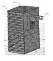
図24のシステムは更に、無線スピーカデバイス500を含む。図25及び26はそれぞれ、無線スピーカデバイス500の例示的な実施形態の前面斜視図及び後面斜視図であり、図27は、無線スピーカデバイス500の例示的な実施形態の機能ブロック図である。図25及び26を参照すると、無線スピーカデバイス500は、前側504(図25)及び後側506(図26)を有する筐体502を含む。例示される実施形態では、筐体502は、長方形の平行六面体として実質的に成形されるが、この形状は1つの例にすぎず、それに限定されない。筐体502は、図27を参照して以下で説明されるように、全ての側面上で閉じられ、無線スピーカデバイス500の様々な構成要素が位置する内部空間を囲む。筐体502は、様々なタイプのプラスチック(例えば、ポリカーボネート、アクリロニトリルブタジエンスチレン(ABS)、ポリエチレンなど)など、好ましくは耐久性があり、非伝導性の(電気的に)任意の適切な材料から構築されてもよい。
The system of FIG. 24 further includes a
図27を参照すると、無線スピーカデバイス500は、プロセッサ508及び通信モジュール510を含む。プロセッサ508及び通信モジュール510は、図27では単一の構成要素として例示されるが、代替的な実施形態では、プロセッサ508及び通信モジュール510は、別個の構成要素を含んでもよい。通信モジュール510は、アンテナ512を含み、ユーザの無線ネットワーク110を通じて無線信号を送信及び受信するための1つ以上の送受信機(図示せず)を含んでもよい。通信モジュール510はまた、別の無線デバイスへの直接接続を介してなど、ユーザの無線ネットワーク110とは独立して、1つ以上のデバイスに無線でデータを伝送し、及び/又は1つ以上のデバイスから無線でデータを受信するように構成されてもよい。1つの例では、無線スピーカデバイス500は、Bluetooth(登録商標)(又は、他の短距離無線プロトコル)接続を介して、ユーザのクライアントデバイス114と通信してもよい。
Referring to FIG. 27, the
代替的な実施形態では、無線スピーカデバイス500は、ユーザの無線ネットワーク110及び/又はネットワーク112への有線接続のために構成されてもよい。例えば、無線スピーカデバイス500は、イーサネット(登録商標)ケーブルなど、ケーブルのコネクタを受けるための1つ以上のポート(図示せず)を含んでもよい。そのような実施形態では、無線スピーカデバイス500は、ケーブルを介して、ユーザの無線ネットワーク110のルータ、又は任意の他のネットワークデバイスに接続してもよい。イーサネット(登録商標)ケーブルを受けるように構成された実施形態では、無線スピーカデバイス500は、パワーオーバイーサネット(登録商標)(PoE)を介して電力が供給されてもよく、パワーオーバイーサネット(登録商標)では、接続されたイーサネット(登録商標)ケーブルを介して、データに沿って電力を渡すことができる。そのような実施形態では、ACピン518が省略されてもよい。代わりに、無線スピーカデバイス500は、ACピン518及びPoE接続の両方を介して電力が供給されてもよい。
In an alternative embodiment, the
プロセッサ508は、以下で説明されるように、データ処理及び様々な他の機能を実行してもよい。プロセッサ508は、プロセッサコア(図示せず)、揮発性メモリ514、不揮発性メモリ516、及び/又はプログラム可能入力/出力周辺機器(図示せず)を含む集積回路を含んでもよい。揮発性メモリ514は、例えば、DDR3(ダブルデータレートタイプの3つの同期ダイナミックランダムアクセスメモリ)を含んでもよい。不揮発性メモリ516は、例えば、NANDフラッシュメモリを含んでもよい。図27に例示される実施形態では、揮発性メモリ514及び不揮発性メモリ516は、プロセッサ508を表すボックス内で例示される。しかしながら、図27に例示される実施形態は例にすぎず、一部の実施形態では、揮発性メモリ514及び/又は不揮発性メモリ516は、必ずしも物理的にプロセッサ508と共に組み込まれないことが理解されよう。揮発性メモリ514及び/又は不揮発性メモリ516は、それらの物理位置に関わらず、本無線スピーカデバイス500の1つ以上の他の構成要素(プロセッサ508に加えて)によって共有されてもよい。
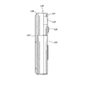
図27を続けて参照すると、無線スピーカデバイス500は更に、無線スピーカデバイス500が標準的なウォールコンセントに差し込まれることを可能にする、AC(交流電流)ピン518のペアを含む。図26を参照すると、ACピン518は、筐体502の後側506から外側に延在する。図27を参照すると、無線スピーカデバイス500は更に、ACメイン電力をDC(直流)に変換するAC/DC整流器520を含み、DCは次いで、無線スピーカデバイス500に電力を供給するためにプロセッサ508に配信される。一部の実施形態はまた、整流器520とプロセッサ508との間でDC−DC変換器(図示せず)を含んでもよい。DC−DC変換器は、整流器520から第1の電圧を入力として受信してもよく、プロセッサ508によって入力として受信された第2の電圧を出力として生成してもよい。
With reference to FIG. 27, the
図27を続けて参照すると、無線スピーカデバイス500は更に、デジタル−アナログ音声変換器524を通じてプロセッサ508に動作可能に接続されたスピーカ522を含む。図25を参照すると、筐体502の前側504は、筐体502内に位置するスピーカ522から周辺環境へのサウンドの通りを促進する、少なくとも1つの開口526を含む。図27を参照すると、無線スピーカデバイス500は更に、ユーザが、機能しない場合のプロセッサ508及び/又は通信モジュール510をリセットすることを可能にする、リセットボタン528及びリセットロジック530を含む。図25及び26を参照すると、筐体502の側面532は、リセットボタン528へのアクセスを提供する小型開口534を含む。ペーパクリップなどの細い物体を挿入することによって、小型開口534を通じて、ユーザは、リセット処理を開始するためにリセットボタンを押圧することができる。
With reference to FIG. 27 in succession, the
図27を参照すると、無線スピーカデバイス500は更に、プロセッサ508に動作可能に接続されたLED536(又は、別のタイプの照明デバイス)を含む。図25を参照すると、LED536は、筐体502の前側504上に位置してもよい。LED536は、ユーザに、無線スピーカデバイス500の現在の動作状態の視覚的インジケータを提供する。例えば、無線スピーカデバイス500がウォールコンセントに差し込まれるとき、LED536は照らされてもよく、無線スピーカデバイス500がフロントドアにおける訪問者に対してユーザを警告するように鳴動するとき、LED536は、設定されたパターンに従って点灯及び消灯してもよい。LED536の点滅又は閃光は特に、聞くことが困難なユーザ、例えば、訪問者がフロントドアにいるときに無線スピーカデバイス500からのサウンドを聞くことができないユーザに対して有益であることがある。
Referring to FIG. 27, the
図24を参照すると、無線A/V記録及び通信ドアベルシステムは更に、API540及び無線スピーカサービス542を含むバックエンドAPI538を含んでもよい。図24は、バックエンドAPI538、API540、及び無線スピーカサービス542をネットワーク112とは別個の構成要素として例示するが、バックエンドAPI538、API540、及び/又は無線スピーカサービス542がネットワーク112の構成要素であると見なされてもよいことが理解されよう。それらの構成要素は、図28を参照して説明され、図28は、本実施形態に従った、無線A/V記録及び通信ドアベル100/130などの無線A/V記録及び通信デバイス、ユーザの無線ネットワーク110などのローカルエリアネットワーク、ネットワーク112などのワイドエリアネットワーク、並びに無線スピーカデバイス500などの無線スピーカデバイスの間で通信するシステム544を例示する機能ブロック図である。
With reference to FIG. 24, the wireless A / V recording and communication doorbell system may further include a
図28のシステムは、1つ以上の構成要素を含む、バックエンドAPI538などのバックエンドAPIを含んでもよい。バックエンドAPI(アプリケーションプログラミングインタフェース)は、例えば、サーバ(例えば、実サーバ、仮想マシン、若しくはクラウドインフラストラクチャ内でサービスとして稼働するマシン)、又は少なくとも1つのAPIをそれにアクセスするクライアント(複数可)に公開する、共にネットワーク化された複数のサーバを含んでもよい。それらのサーバは、どの他の構成要素が含まれるかに応じて、キャッシュ層、データベース層、又は他の構成要素など、アプリケーションサーバ(例えば、ソフトウェアサーバ)などの構成要素を含んでもよい。バックエンドAPIは、例えば、その各々がそれらのパブリックAPIを使用して相互に通信する、多くのそのようなアプリケーションを含んでもよい。一部の実施形態では、APIバックエンドは、ユーザデータの大部分を保持してもよく、ユーザ管理能力を供給してもよく、クライアントを非常に制限された状態を有するようにさせる。
The system of FIG. 28 may include a backend API, such as a
図28に例示されるバックエンドAPI538は、API540などの1つ以上のAPIを含んでもよい。APIは、ソフトウェア及びアプリケーションを構築するためのルーチン、プロトコル、及びツールのセットである。APIは、その動作、入力、出力、及び基本的なタイプに関するソフトウェア構成要素を表し、インタフェースに影響を与えることなく定義及び実装態様が変わることを可能にする、それぞれの実装態様とは独立した機能性を定義する。有利なことに、APIは、プログラマがアプリケーション自体を修正する必要なく、又はアプリケーションがどのように作用しているかをさえも理解する必要なく、プログラマにアプリケーションの機能性へのアクセスを提供することができる。APIは、ウェブベースシステム、オペレーティングシステム、又はデータベースシステム用であってもよく、それは、所与のプログラミング言語を使用して、そのシステムについてのアプリケーションを開発するための設備を提供する。データベース、ハードディスクドライブのようなコンピュータハードウェア、又はビデオカードにアクセスすることに加えて、APIは、プログラミンググラフィカルユーザインタフェース(GUI)構成要素の作用を容易にすることができる。例えば、APIは、既存のアプリケーションへの新たな特徴の統合(いわゆる「プラグインAPI」)を容易にすることができる。APIはまた他に、共有データにより異なるアプリケーションを支援することができ、共有データは、アプリケーションの機能性を統合及び強化することを支援することができる。
The
図28に例示されるバックエンドAPI538は更に、無線スピーカサービス542など、1つ以上のサービス(ネットワークサービスとも称される)を含んでもよい。ネットワークサービスは、データ記憶、操作、提示、通信、及び/又は他の能力を提供するアプリケーションである。ネットワークサービスは、アプリケーション層ネットワークプロトコルに基づいて、クライアント−サーバアーキテクチャを使用して実施されることが多い。各々のサービスは、1つ以上のコンピュータ(複数のサービスを供給する専用サーバコンピュータなど)上で稼働するサーバ構成要素によって提供されてもよく、他のデバイス上で稼働するクライアント構成要素によってネットワークを介してアクセスされてもよい。しかしながら、クライアント及びサーバ構成要素は両方とも、同一のマシン上で稼働することができる。クライアント及びサーバは、ユーザインタフェース、及び時にそれらと関連付けられた他のハードウェアを有してもよい。
The back-
図28に例示されるバックエンドAPI538は、無線スピーカサービス542などの無線スピーカサービスを含む。無線スピーカサービス542は、無線スピーカデバイス500などの複数の無線スピーカデバイスに関する情報を記憶した1つ以上の無線スピーカデータ構造546を含んでもよい。例えば、情報は、無線A/V記録及び通信デバイス100など、各々の無線スピーカデバイス並びに少なくとも1つの関連する無線A/V記録及び通信デバイスに関する情報を含んでもよい。無線スピーカサービス542は、以下で更に説明されるように、どの無線スピーカデバイス(複数可)がバックエンドAPI538に訪問者検出信号550を送信する無線A/V記録及び通信デバイスと関連付けられるかを判定することが必要とされるとき、無線スピーカデータ構造(複数可)546内の情報にアクセスしてもよい。無線スピーカサービス542はまた、無線スピーカデータ構造(複数可)546内で情報を維持してもよく、新たな無線スピーカデバイスが活性化されるとき、既存の無線スピーカデバイスが非活性化されるとき、並びに/又は既存の無線スピーカデバイスと無線A/V記録及び通信デバイスとの間の関連付けが変更されるとき、無線スピーカデータ構造(複数可)546内の情報を更新してもよい。一部の実施形態では、無線スピーカサービス542は、無線スピーカデバイス500との持続的な接続を有してもよい。持続的な接続は有利なことに、以下で更に説明されるように、無線スピーカサービス542と無線スピーカデバイス500との間の待ち時間を減少させる。
The back-
無線A/V記録及び通信ドアベルと関連して本無線スピーカデバイス500を使用するために、ユーザは、標準的なウォールコンセントに無線スピーカデバイス500のACピン518を差し込み、次いで、ユーザの無線ネットワーク110(図24)に無線スピーカデバイス500を接続する。ユーザは次いで、セットアップ処理を通じて案内されてもよく、セットアップ処理では、無線スピーカデバイス500がユーザのドアベル100と関連付けられ、関連付けがデータ構造に記憶され、その結果、訪問者がドアベルボタン133を押下するとき、システムは、どの無線スピーカデバイス500を活性化するかを把握する。例えば、セットアップ処理は、ユーザのクライアントデバイス114上でアプリケーションを実行することを含んでもよい。無線スピーカデバイス500が成功して無線ネットワーク110に接続された後、プロンプトがユーザのクライアントデバイス114上に表示されてもよい。プロンプトは、無線スピーカデバイス500に関連付ける、ドアベル又はセキュリティカメラなどの無線A/V記録及び通信デバイスを選択するようにユーザに要求することができる。ユーザが選択を行うとき、ユーザのクライアントデバイス114は、無線ネットワーク110及びネットワーク112を介して、バックエンドAPI538に信号を送信してもよく、無線スピーカサービス542は、無線スピーカデータ構造(複数可)546内の情報を更新してもよく、その結果、無線スピーカデバイス500は、ユーザにより選択された無線A/V記録及び通信デバイスと関連付けられる。後に、以下で更に説明されるように、動きイベント及び/又はボタン押下イベントがユーザにより選択された無線A/V記録及び通信デバイスによって開始されるとき、無線スピーカサービス542は、関連する無線スピーカデバイス500に信号を送信し、無線スピーカデバイス500は、トーンを発する。
To use the
ユーザの無線A/V記録及び通信ドアベル100はまた、無線ネットワーク110に接続される。以下で詳細に説明されるように、訪問者が無線A/V記録及び通信ドアベル100において検出されるとき、ドアベル100は、無線ネットワーク110(LAN)を介して、API540(WAN)に信号を送信する。API540は次いで、無線スピーカサービス542に信号を送信し、無線スピーカサービス542は、LANを介して無線スピーカデバイス500に信号を送信する。無線スピーカデバイス500は次いで、訪問者が無線A/V記録及び通信ドアベル100において検出された無線スピーカデバイス500の聞こえる範囲内で、任意の人間(複数可)に警告するようにトーンを発する。上記説明されたように、一部の実施形態では、無線スピーカサービス542は、無線スピーカデバイス500との持続的な接続を有してもよい。持続的な接続は有利なことに、無線スピーカサービス542と無線スピーカデバイス500との間の待ち時間を減少させ、その結果、無線スピーカサービス542が無線スピーカデバイス500にトーンを送信するとき、送信されているトーン信号554とそのスピーカ522からトーンを発する無線スピーカデバイス500との間のいずれの遅延はほとんどない。例えば、持続的な接続を理由に、無線スピーカデバイス500がトーン信号554を受信することができる前に、無線スピーカデバイス500が無線スピーカサービス542上でそれ自体を再確立する必要性がない。
The user's wireless A / V recording and
図28のシステムでは、及び図29を参照すると、無線A/V記録及び通信ドアベル100は、ドアベル100の視野内で訪問者を検出してもよい。例えば、無線A/V記録及び通信ドアベル100は、カメラ102、134、及び/若しくは動きセンサ(複数可)144を使用して動きを検出することによって、並びに/又は訪問者がA/V記録及び通信ドアベル100/130上のボタン133を押圧したことを検出することによって、訪問者の存在を検出してもよい。訪問者を検出したことに応答して、無線A/V記録及び通信ドアベル100は、API540に訪問者検出信号550(図29)を送信してもよく、API540は、無線A/V記録及び通信ドアベル100から訪問者検出信号550を受信してもよい。訪問者検出信号550は、感知された動きを介して、又はボタン押下を介して訪問者が検出されたかなど、訪問者−検出イベントに関する情報を含んでもよい。図24及び29を参照すると、無線A/V記録及び通信ドアベル100は、LANとすることができるユーザの無線ネットワーク110、及びWANとすることができるネットワーク112を介して、API540に訪問者検出信号550を送信する。
In the system of FIG. 28 and with reference to FIG. 29, the wireless A / V recording and
図28及び29を参照すると、API540は、無線A/V記録及び通信ドアベル100から訪問者検出信号550を受信したことに応答して、無線スピーカサービス542に無線スピーカ活性化信号552を伝送してもよく、無線スピーカサービス542は、API540から無線スピーカ活性化信号552を受信してもよい。API540から無線スピーカ活性化信号552を受信したことに応答して、無線スピーカサービス542は、無線スピーカデータ構造(複数可)546にアクセスしてもよく、無線スピーカ活性化信号552内の識別情報に基づいて、無線スピーカデバイス500などの少なくとも1つの無線スピーカデバイス500を判定してもよく、少なくとも1つの無線スピーカデバイス500と、訪問者検出信号550を送信した無線A/V記録及び通信ドアベル100が関連付けられる。無線スピーカサービス542は次いで、無線スピーカデータ構造(複数可)546から判定された少なくとも1つの無線スピーカデバイス500にトーン信号554を送信してもよく、少なくとも1つの無線スピーカデバイス500は、無線スピーカサービス542からトーン信号554を受信してもよい。トーン信号554は、少なくとも1つの無線スピーカデバイス500のスピーカ522からトーンを発するための、少なくとも1つの無線スピーカデバイス500へのコマンドを含む。よって、無線スピーカサービス542からトーン信号554を受信したことに応答して、少なくとも1つの無線スピーカデバイス500は、訪問者が無線A/V記録及び通信ドアベル100において検出されたスピーカ522の聞こえる範囲内で任意の人間(複数可)に通知するように、そのスピーカ522からトーンを発してもよい。
Referring to FIGS. 28 and 29, the
上記説明されたように、一部の実施形態では、無線スピーカサービス542は、無線スピーカデバイス500との持続的な接続を有してもよい。持続的な接続は有利なことに、無線スピーカサービス542と無線スピーカデバイス500との間の待ち時間を減少させ、その結果、無線スピーカサービス542が無線スピーカデバイス500にトーン信号554を送信するとき、送信されているトーン信号554とそのスピーカ522からトーンを発する無線スピーカデバイス500との間でいずれの遅延はほとんどない。例えば、持続的な接続を理由に、無線スピーカデバイス500がトーン信号554を受信することができる前に、無線スピーカデバイス500が無線スピーカサービス542上でそれ自体を再確立する必要性がない。
As described above, in some embodiments, the
上記説明されたように、本実施形態は有利なことに、ドアベルなどの無線A/V記録及び通信デバイスと共に使用するように構成された無線スピーカデバイスを提供する。スピーカを含む無線スピーカデバイスは、標準的なウォールコンセントに差し込まれてもよく、Wi−Fiネットワークなどのユーザのローカルエリアネットワーク(LAN)に接続してもよい。LANは、インターネット及び/又は公衆交換電話網(PSTN)などのワイドエリアネットワーク(WAN)に接続される。無線A/V記録及び通信デバイスが訪問者を検出するとき、それは、LANを介して、サーバ及び/又はサービスなど、WAN内の少なくとも1つのデバイスに信号を送信する。それに応答して、WAN内の少なくとも1つのデバイスは、LANを介して、無線スピーカデバイスに信号を送信する。無線スピーカデバイスへの信号は、無線スピーカデバイスがそのスピーカを通じてトーンを発するためのコマンドを含む。無線スピーカデバイスは次いで、ユーザに訪問者が無線A/V記録及び通信デバイスにいることを警告するために、そのスピーカを通じてトーンを発する。 As described above, the present embodiment advantageously provides a wireless speaker device configured for use with a wireless A / V recording and communication device such as a doorbell. The wireless speaker device, including the speaker, may be plugged into a standard wall outlet or connected to a user's local area network (LAN), such as a Wi-Fi network. The LAN is connected to the Internet and / or a wide area network (WAN) such as the Public Switched Telephone Network (PSTN). When a wireless A / V recording and communication device detects a visitor, it sends a signal over the LAN to at least one device in the WAN, such as a server and / or service. In response, at least one device in the WAN sends a signal to the wireless speaker device over the LAN. The signal to the wireless speaker device includes commands for the wireless speaker device to emit a tone through its speaker. The wireless speaker device then emits a tone through its speaker to warn the user that the visitor is on the wireless A / V recording and communication device.
一部の実施形態では、無線スピーカ活性化信号552及び/又はトーン信号554は、無線スピーカデバイス500のスピーカ522によって発されることになるトーンのタイプに関する情報を含んでもよい。例えば、トーンのタイプは、処理を開始した訪問者の検出のタイプに依存してもよい。訪問者が動きを介して検出された場合、第1のタイプのトーンがスピーカ522によって発せされてもよく、無線スピーカ活性化信号552及び/又はトーン信号554は、第1のタイプのトーンを発するための、無線スピーカデバイス500へのコマンドを含んでもよい。訪問者がボタン押下を介して検出された場合、第2のタイプのトーンは、スピーカ522によって発せされてもよく、無線スピーカ活性化信号552及び/又はトーン信号554は、第2のタイプのトーンを発するための、無線スピーカデバイス500へのコマンドを含んでもよい。様々なタイプのトーンは、無線スピーカデバイス500の不揮発性メモリ516に記憶されてもよい。任意の数の異なるトーンは、無線スピーカデバイス500に記憶されてもよい。上記説明された第1及び第2のタイプは、非限定的な例にすぎない。
In some embodiments, the wireless
一部の実施形態では、無線スピーカデバイス500のスピーカ522によって発せられたトーンは、ユーザによって構成可能であってもよい。例えば、ユーザのクライアントデバイス114上で実行するアプリケーションは、メニューを表示してもよく、メニューから、ユーザは、複数の異なるトーンから選択することができる。トーンは、製造の時点において無線スピーカデバイス500に記憶されてもよい。代わりに、又は加えて、トーンは、不揮発性メモリ516においてなど、無線スピーカデバイス500にダウンロード及び記憶されてもよい。例えば、ユーザは、クライアントデバイス114を使用して、バックエンドAPI538においてなど、ネットワーク112内の1つ以上のサーバに記憶されたトーンにアクセスしてもよい。ユーザは、ネットワーク112から1つ以上のトーンを選択することができ、無線ネットワーク110及びプロセッサ/通信モジュール508/510を介して、無線スピーカデバイス500にそれらをダウンロードすることができる。代わりに、又は加えて、ユーザは、無線ネットワーク110及びプロセッサ/通信モジュール508/510を介して、クライアントデバイス114から無線スピーカデバイス500にトーンを転送してもよい。
In some embodiments, the tones emitted by
一部の実施形態では、無線スピーカデバイス500のスピーカ522によって発せられたトーンは、複数の異なる無線A/V記録及び通信デバイスのうちのどれが訪問者検出信号550を生成したかに応じて変わってもよい。例えば、無線スピーカデバイス500は、1つよりも多い無線A/V記録及び通信デバイスと関連付けられてもよい。次いで、無線スピーカデバイス500は、無線スピーカデバイス500と関連付けられた第1の無線A/V記録及び通信デバイスによって訪問者検出信号550が生成されるとき、第1のタイプのトーンを発してもよく、無線スピーカデバイス500は、無線スピーカデバイス500と関連付けられた第2の無線A/V記録及び通信デバイスによって訪問者検出信号550が生成されるとき、第2のタイプのトーンを発してもよい。無線スピーカデバイス500は、任意の数の無線A/V記録及び通信デバイスと関連付けられてもよい。上記説明された第1及び第2の関連付けられた無線A/V記録及び通信デバイスは、非限定的な例にすぎない。
In some embodiments, the tone emitted by the
代替的な実施形態では、無線スピーカデバイス500は、動きセンサ(図示せず)を含んでもよい。無線スピーカデバイス500の動きセンサが動きを検出するとき、無線スピーカデバイス500は、バックエンドAPI538に信号を送信してもよい。信号は、上記説明された訪問者検出信号550と同様であってもよい。無線スピーカデバイス500から信号を受信したことに応答して、バックエンドAPI538は、1つ以上の接続されたデバイスに、無線スピーカデバイス500によって動きが検出されたことをユーザに警告するための信号を送信してもよい。例えば、バックエンドAPI538は、ユーザのクライアントデバイス114に信号を送信してもよい。
In an alternative embodiment, the
代替的な実施形態では、無線スピーカデバイス500は、マイクロフォン(図示せず)を含んでもよい。そのような実施形態では、ユーザは、無線スピーカデバイス500のマイクロフォン及びスピーカ522を使用して、無線スピーカデバイス500並びに無線A/V記録及び通信デバイスを通じて訪問者と通信してもよい。
In an alternative embodiment, the
一部の実施形態では、無線スピーカデバイス500は、別の無線デバイスからのストリーミング音声を再生する能力を有することができる。例えば、無線スピーカデバイス500は、Bluetooth(登録商標)接続を介して、ユーザのクライアントデバイス114から無線音声信号を受信してもよく、無線スピーカデバイス500は、スピーカ522を介して音声を再生してもよい。
In some embodiments, the
図30及び31はそれぞれ、無線スピーカデバイス600の別の例示的な実施形態の前面斜視図及び後面斜視図であり、図32は、図30及び31の無線スピーカデバイス600の機能ブロック図である。図30〜32の無線スピーカデバイス600は、図30〜32を参照すると、前側604(図30)及び後側606(図31)を有する筐体602、プロセッサ608(図32)、通信モジュール610、AC(交流電流)ピン518のペア、AC/DC整流器520、スピーカ522、デジタル−アナログ音声変換器524、筐体602内に位置するスピーカ522から周辺環境へのサウンドの通りを促進する筐体602の前側604内の少なくとも1つの開口612、リセットボタン528、リセットロジック530、リセットボタン528へのアクセスを提供する筐体602の側面616内の小型開口614、及びLED536を含む、図25〜27の対応する構成要素に構造及び/又は機能において類似するいくつかの構成要素を含む。再度、それらの構成要素の多くは、図25〜27の構成要素に構造及び/又は機能において類似する。したがって、以下の説明は、図25〜27の構成要素とは異なるそれらの構成要素の態様に焦点を当てる。
30 and 31 are front and rear perspective views of another exemplary embodiment of the
図27に示される実施形態とは対照的に、図32に示される実施形態では、プロセッサ608及び通信モジュール610は、別個の構成要素として例示され、揮発性メモリ618及び不揮発性メモリ620は、プロセッサ608及び通信モジュール610の両方とは別個に例示される。通信モジュール610は、第1及び第2のアンテナ622(図30及び31にも示される)を含み、ユーザの無線ネットワーク110を通じて無線信号を送信及び受信するための1つ以上の送受信機(図示せず)を含んでもよい。通信モジュール610はまた、別の無線デバイスへの直接接続を介してなど、ユーザの無線ネットワーク110とは独立して、1つ以上のデバイスに無線でデータを伝送し、及び/又は1つ以上のデバイスから無線でデータを受信するように構成されてもよい。1つの例では、無線スピーカデバイス600は、他の無線デバイスへの無線スピーカデバイス600の近接性に応じて、Bluetooth(登録商標)(又は、他の短距離無線プロトコル)接続を介して、ユーザのクライアントデバイス114などの別の無線デバイスと通信してもよい。よって、通信モジュール610は、無線スピーカデバイス600がWi−Fi(IEEE802.11)、Bluetooth(登録商標)、ZigBee(登録商標)(IEEE802.15.4)、又は任意の他のプロトコルなどの様々なデータ伝送プロトコルを通じて無線で通信することを可能にする、1つ以上のチップ(集積回路)などの構成要素(複数可)を含んでもよい。
In the embodiment shown in FIG. 32, in contrast to the embodiment shown in FIG. 27, the
代替的な実施形態では、無線スピーカデバイス600は、ユーザの無線ネットワーク110及び/又はネットワーク112への有線接続のために構成されてもよい。例えば、無線スピーカデバイス600は、イーサネット(登録商標)ケーブルなどのケーブルのコネクタを受けるための1つ以上のポート(図示せず)を含んでもよい。そのような実施形態では、無線スピーカデバイス600は、ケーブルを介して、ユーザの無線ネットワーク110のルータ、又は任意の他のネットワークデバイスに接続してもよい。イーサネット(登録商標)ケーブルを受けるように構成された実施形態では、無線スピーカデバイス600は、パワーオーバイーサネット(PoE)を介して電力が供給されてもよく、パワーオーバイーサネット(登録商標)では、接続されたイーサネット(登録商標)ケーブルを介して、データに沿って電力を渡すことができる。そのような実施形態では、ACピン518が省略されてもよい。代わりに、無線スピーカデバイス600は、ACピン518及びPoE接続の両方を介して電力が供給されてもよい。
In an alternative embodiment, the
図32を更に参照すると、プロセッサ608は、以下で説明されるように、データ処理及び様々な他の機能を実行してもよい。プロセッサ608は、プロセッサコア(図示せず)及び/又はプログラム可能入力/出力周辺機器(図示せず)を含む集積回路を含んでもよい。プロセッサ608は、揮発性メモリ618及び/又は不揮発性メモリ620にアクセスしてもよい。揮発性メモリ618は、例えば、DDR3(ダブルデータレートタイプの3つの同期ダイナミックランダムアクセスメモリ)を含んでもよい。不揮発性メモリ620は、例えば、NANDフラッシュメモリを含んでもよい。図32に例示される実施形態では、揮発性メモリ618及び不揮発性メモリ620は、プロセッサ608とは別個の構成要素として例示される。しかしながら、図32に例示される実施形態は例にすぎず、一部の実施形態では、揮発性メモリ618及び/又は不揮発性メモリ620は、必ずしも物理的にプロセッサ608とは別個ではないことが理解されよう。揮発性メモリ618及び/又は不揮発性メモリ620は、それらの物理位置に関わらず、本無線スピーカデバイス600の1つ以上の他の構成要素(プロセッサ608に加えて)によって共有されてもよい。
Further referring to FIG. 32,
図32を続けて参照すると、無線スピーカデバイス600の通信モジュール610は更に、無線リピータ624(無線範囲エキステンダとも称されてもよい)を含んでもよい。無線リピータ624は、ユーザの無線ネットワーク110内の無線ルータ(又は、別のネットワークデバイス)から無線信号を受信し、信号を再ブロードキャストするように構成される。無線ルータのブロードキャスト範囲内になく、又は単に無線ルータから無線信号を弱く受信する無線デバイスは、無線スピーカデバイス600から再ブロードキャストされた信号を受信してもよく、よって、無線スピーカデバイス600を通じてユーザの無線ネットワーク110に接続してもよい。一部の実施形態では、無線リピータ624は、データを伝送及び受信し、例えば、Wi−Fi(IEEE802.11)、WiMAX(IEEE802.16)、又は任意の他のプロトコル及び/若しくは技術など、1つ以上のプロトコル及び/又は技術を使用することができる1つ以上の送受信機モジュール(図示せず)を含んでもよい。
With reference to FIG. 32 in succession, the
上記説明されたように、通信モジュール610は、第1及び第2のアンテナ622(図30〜32)を含み、無線信号を送信及び受信するための1つ以上の送受信機(図示せず)を含んでもよい。第1及び第2のアンテナ622は、無線スピーカデバイス600が多入力多出力(MIMO)を介して無線で通信することを可能にする。MIMOは、マルチパス伝播を利用するために複数の伝送及び受信アンテナを使用して、無線リンクの能力を増大させるための技術である。図31及び32に示されるように、第1及び第2のアンテナ622は、無線スピーカデバイス600の筐体602の反対側面から延在してもよい。しかしながら、例示される構成は1つの例にすぎず、それに限定されない。第1及び第2のアンテナ622は、筐体602に対して固定又は移動可能であってもよい。例えば、第1及び第2のアンテナ622は、筐体602を通じて両方のアンテナ622に垂直に延在する軸の周りを枢動可能であってもよい。
As described above, the
通信モジュール610はまた、別の無線デバイスへの直接接続を介してなど、ユーザの無線ネットワーク110とは独立して、1つ以上のデバイスに無線でデータを伝送し、及び/又は1つ以上のデバイスから無線でデータを受信するように構成されてもよい。1つの例では、無線スピーカデバイス600は、他の無線デバイスへの無線スピーカデバイス600の近接性に応じて、Bluetooth(登録商標)(又は、他の短距離無線プロトコル)接続を介して、ユーザのクライアントデバイス114などの別の無線デバイスと通信してもよい。よって、通信モジュール610は、無線スピーカデバイス600がWi−Fi(登録商標)(IEEE802.11)、Bluetooth(登録商標)、ZigBee(登録商標)(IEEE802.15.4)、又は任意の他のプロトコルなどの様々なデータ伝送プロトコルを通じて無線で通信することを可能にする、1つ以上のチップ(集積回路)など、1つ以上のモジュール(複数可)又は構成要素(複数可)を含んでもよい。
The
様々な実施形態では、無線スピーカデバイス600は、1つ以上の他の無線デバイスを無線で制御するために使用されてもよい。例示的な無線で制御可能なデバイスの非包括的及び非限定的なリストは、電子ロック、アラーム、アラーム監視システム、セキュリティシステム、ガレージドアオープナ、電機ゲート、自動セキュリティゲート、テレビ、カメラ、ビデオストリーミングデバイス、ビデオ記録及びビデオ受信デバイス、デジタルビデオレコーダ、デジタルビデオストリーミングデバイス、無線対応電機プラグコンセント、照明システム、ライト、光センサ及びスイッチ、光スイッチ、照明制御パネル、電球、電球についての固定具、又は任意の他のタイプの無線で制御可能なデバイス若しくは構成要素を含む。
In various embodiments, the
様々な実施形態では、他のデバイスは、ユーザの無線ネットワーク110を通じて送信された信号、無線スピーカデバイス600と1つ以上の他の無線デバイスとの間で直接送信された信号、又はそのような信号の任意の組み合わせにより、無線スピーカデバイス600を通じて無線で制御されてもよい。例えば、図33を参照すると、ユーザのクライアントデバイス114上で実行するアプリケーションは、ユーザが無線スピーカデバイス600を介してユーザのクライアントデバイス114と他の無線デバイス626との間で送信された信号により別の無線デバイス626を制御することを可能にすることができる。1つの例では、ユーザのクライアントデバイス114及び無線スピーカデバイス600は、Bluetooth(登録商標)接続(又は、近接近したデバイスの間で相互に近距離を通じてデータを交換するための別の無線技術標準)を通じてなど、信号628を相互に直接送信してもよく、無線スピーカデバイス600及び他の無線デバイス626は、Bluetooth(登録商標)接続(又は、近接近したデバイスの間で相互に近距離を通じてデータを交換するための別の無線技術標準)を通じてなど、信号630を相互に直接送信してもよい。別の例では、ユーザのクライアントデバイス114及び無線スピーカデバイス600は、Wi−Fi(登録商標)ネットワーク(又は、別の無線技術標準)などのユーザの無線ネットワーク110を介して信号632、634を相互に送信してもよく、無線スピーカデバイス600及び他の無線デバイス626は、ユーザの無線ネットワーク110を介して信号636、634を相互に送信してもよい。更なる別の例では、ユーザのクライアントデバイス114、無線スピーカデバイス600、及び他の無線デバイス626は、それらの信号628、630、632、634、636の混合を介して信号を相互に送信してもよい。例えば、ユーザのクライアントデバイス114及び無線スピーカデバイス600は、信号628を介して相互に直接通信してもよく、無線スピーカデバイス600及び他の無線デバイス626は、ユーザの無線ネットワーク110を通じて送信された信号634、636を介して相互に通信してもよい。代わりに、ユーザのクライアントデバイス114及び無線スピーカデバイス600は、ユーザの無線ネットワーク110を通じて送信された信号632、634を介して相互に通信してもよく、無線スピーカデバイス600及び他の無線デバイス626は、信号630を介して相互に直接通信してもよい。
In various embodiments, the other device is a signal transmitted through the user's
図32を参照すると、無線スピーカデバイス600は更に、1つ以上の認証モジュール638を含んでもよい。認証モジュール638は、無線スピーカデバイス600と1つ以上の他の電子デバイスとの間の機能性を認証するように構成された集積回路を含んでもよい。1つの非限定的な例では、認証モジュール638は、無線スピーカデバイス600とApple Inc.によって作成された1つ以上の他の電子デバイスとの間の機能性を認証するように構成されたMFi(「iPhone(登録商標)/iPod(登録商標)/iPad(登録商標)のために作成された」)チップを含んでもよい。
With reference to FIG. 32, the
図34〜37は、本開示に従った、無線ネットワークに本無線スピーカデバイス600を接続し、本無線スピーカデバイス600に1つ以上の無線デバイスを接続する処理の実施形態を例示する。図34を参照すると、ユーザのクライアントデバイス114は最初に、ユーザの無線ネットワーク110に接続されてもよく(両矢印640によって示されるように)、無線スピーカデバイス600は、任意の他のデバイス又はネットワークに接続されず、電力をオフにされてもよい。一部の実施形態では、ユーザの無線ネットワーク110に無線スピーカデバイス600を接続する処理は、ユーザのクライアントデバイス114上で実行するアプリケーションによって容易にされてもよい。ユーザの無線ネットワーク110に無線スピーカデバイス600を接続する他の処理は、アプリケーションを参照する以下の説明を明確にするために、ユーザのクライアントデバイス114上で実行するそのようなアプリケーションを含まなくてもよい。
FIGS. 34 to 37 illustrate an embodiment of a process of connecting the
ユーザのクライアントデバイス114上で実行するアプリケーションは、無線スピーカデバイス600の電力をオンにするようにユーザを促すことができる。その後、無線スピーカデバイス600は、標準的なウォールコンセントにACピン518を差し込むことによってなど、電力をオンにされてもよい。無線スピーカデバイス600は次いで、AP(アクセスポイント)モードにあってもよく、APモードでは、それは、無線プロビジョニングビーコンをブロードキャストする。プロビジョニングビーコンは、他の無線デバイスに、無線スピーカデバイス600が無線アクセスポイントであることを示すブロードキャスト無線信号である。プロビジョニングビーコンは、SSID(サービスセット識別子)などの識別情報を含む。プロビジョニングビーコンはまた、無線アクセスポイントのセキュリティが開放されている(無線アクセスポイントに接続するためにパスワードが必要とされない)ことを示してもよい。
An application running on the user's
ユーザのクライアントデバイス114上で実行するアプリケーションは、アプリケーションを終了し、ユーザの無線ネットワーク110からユーザのクライアントデバイス114を切断し、無線スピーカデバイス600の無線アクセスポイントにユーザのクライアントデバイス114を接続するようにユーザを促すことができる。図35を参照すると、ユーザのクライアントデバイス114は次いで、ユーザの無線ネットワーク110から切断してもよく、無線スピーカデバイス600の無線アクセスポイントに接続してもよい(両矢印642によって示されるように)。ユーザのクライアントデバイス114は次いで、無線スピーカデバイス600に、無線ルータなど、ユーザの無線ネットワーク110内のネットワークデバイスについての認証情報を伝送してもよい。ユーザのクライアントデバイス114が前にユーザの無線ネットワーク110に接続されたことを理由に、それは、そのメモリ(又は、記憶装置)に無線ルータ(又は、別のネットワークデバイス)についての認証情報を記憶していることがある。ネットワークデバイスについての認証情報は、SSIDなどのネットワークデバイスについての識別子、及び/又はネットワークデバイスに接続するためにパスワードが必要とされる場合にパスワードを含んでもよい。
An application running on the user's
図36を参照すると、無線スピーカデバイス600は次いで、ユーザのクライアントデバイス114によって提供された認証情報を使用して、ユーザの無線ネットワーク110内のネットワークデバイスに接続してもよい(両矢印644によって示されるように)。無線スピーカデバイス600は次いで、ユーザの無線ネットワーク110及び/又はネットワーク112を介してバックエンドAPI538と通信してもよい。バックエンドAPI538は、無線スピーカデバイス600についての認証情報を生成し、無線スピーカデバイス600に生成された認証情報を伝送してよい。認証情報は、以下で説明されるように、プロビジョニングビーコンが無効にされた後、無線リピータ624(及び、無線アクセスポイント)として動作している無線スピーカデバイス600に役立つことができる。無線スピーカデバイス600についての認証情報は、以下で説明されるように、SSIDなどの無線スピーカデバイス600についての識別子、及び/又は無線スピーカデバイス600がリピータモードに遷移した後に無線スピーカデバイス600に接続するために他のデバイスが提供することが必要とされるパスワードを含んでもよい。パスワードは、Wi−Fi保護アクセス(WPA)、Wi−Fi保護アクセスII(WPA2)、有線同等プライバシ(WEP)、又は任意の他のセキュリティプロトコルなど、任意の適切なセキュリティプロトコルを含んでもよい。
Referring to FIG. 36, the
無線スピーカデバイス600がバックエンドAPI538から認証情報を受信した後、無線スピーカデバイス600は、プロビジョニングビーコンを無効にして、リピータモードに遷移してもよい。図37を参照すると、リピータモードでは、無線スピーカデバイス600は、ユーザの無線ネットワーク110内の無線アクセスポイント(例えば、ルータ)に接続され(両矢印644によって示されるように)、また、他の無線デバイスについての無線アクセスポイントを提供する。この構成では、無線スピーカデバイス600は、ユーザの無線ネットワーク110内で無線アクセスポイント(例えば、ルータ)との局(無線クライアント又はノードとも称される)の接続を維持することができ、また、他の無線デバイスについての無線アクセスポイントを提供することができる。例えば、図37に示されるように、無線A/V記録及び通信ドアベル100は、無線スピーカデバイス600によって提供された無線アクセスポイントに接続してもよい(破線の両矢印646によって示されるように)。例えば、無線スピーカデバイス600が、ユーザの無線ネットワーク110内の無線アクセスポイント(例えば、ルータ)によって提供された信号と比較して、無線A/V記録及び通信ドアベル100により強い信号を提供する場合、無線A/V記録及び通信ドアベル100は、無線スピーカデバイス600を介してユーザの無線ネットワーク110に接続してもよい。リピータモードでは、無線スピーカデバイス600は、無線スピーカデバイス600によって提供された無線アクセスポイントの存在を告知するために、ビーコンフレームを定期的にブロードキャストしてもよい。
After the
上記説明されたように、バックエンドAPI538は、無線スピーカデバイス600についての認証情報を生成してもよく、無線スピーカデバイス600に生成された認証情報を伝送してもよい。一部の実施形態では、無線スピーカデバイス600について生成された識別子(例えば、SSID)は、各々のユーザに対して一意であってもよく、それは有利なことに、隣接するユーザが相互の帯域幅を使用することを防止する。一部の実施形態では、それにも関わらず、同一のユーザに属する複数の無線スピーカデバイス600が同一の(又は、同様の)認証情報を受信することができる。よって、所与のユーザが1つよりも多い無線スピーカデバイス600を有する場合、バックエンドAPI538は、ユーザが1つよりも多い無線スピーカデバイス600を有することを認識することができ、ユーザの既存の無線スピーカデバイス(複数可)600の認証情報への1つ以上の事項において類似する新たに接続された無線スピーカデバイス600についての認証情報を生成することができる。例えば、2つ以上の無線スピーカデバイス600が同一の識別子及び/又はパスワードを有する場合、無線スピーカデバイス600は、ローミングネットワークを形成してもよく、ローミングネットワークでは、2つ以上の無線スピーカデバイス600が、同一の(又は、同様の)認証情報を有する複数の無線アクセスポイントを提供する。ローミングネットワークでは、無線デバイスは、同一の(又は、同様の)認証情報を有する無線アクセスポイントのいずれかに接続してもよく、その結果、所与の無線デバイスは、例えば、その現在の位置においてその無線デバイスに最も強い信号を提供するいずれかの無線アクセスポイントに接続することができる。無線デバイスが第1の位置から第2の位置に移動し、第1の無線アクセスポインが第1の位置において最も強い信号を提供するが、第2の無線アクセスポイントが第2の位置において最も強い信号を提供する場合、第1及び第2の無線アクセスポイントが同一の(又は、同様の)認証情報を有することを理由に、無線デバイスは、ユーザ介入に対するいかなる必要もなく、第1の無線アクセスポイントから第2の無線アクセスポイントに容易に切り替えることができる。よって、ローミングネットワークは、各々の無線デバイスがローミングネットワーク内の任意の所与の位置において最良の利用可能な無線信号を享受し、無線デバイスの位置などの1つ以上の条件が変化するにつれて、1つの無線アクセスポイントから別の無線アクセスポイントに容易に遷移することを可能にする。
As described above, the
一部の実施形態では、ローミングネットワークは、少なくともユーザの無線ネットワーク110内の無線アクセスポイント(例えば、ルータ)が、ローミングネットワーク内の無線スピーカデバイス(複数可)600とは異なる識別子(例えば、SSID)及び/又はパスワードを有することがあることを理由に、ユーザの無線ネットワーク110内で無線アクセスポイント(例えば、ルータ)を含まなくてもよい。しかしながら、一部の実施形態では、ユーザの無線ネットワーク110内の無線アクセスポイント(例えば、ルータ)は、代替的な無線アクセスポイントとして無線デバイスに対して利用可能であってもよい。例えば、ローミングネットワーク内の無線スピーカデバイス(複数可)600の認証情報とは異なる場合の、ユーザの無線ネットワーク110内の無線アクセスポイント(例えば、ルータ)の認証情報は、ローミングネットワークに接続する無線デバイスに提供されてもよい。そのような実施形態では、ユーザの無線ネットワーク110内の無線アクセスポイント(例えば、ルータ)は、無線スピーカデバイス(複数可)600のアクセスポイント(複数可)が利用可能でない場合に、代替的なアクセスポイントとしてそのような無線デバイスに対して利用可能であってもよい。
In some embodiments, the roaming network has at least an identifier (eg, SSID) in which the wireless access point (eg, router) in the user's
一部の実施形態では、無線スピーカデバイス600について生成された識別子は、無線スピーカデバイス600が接続されたユーザの無線ネットワーク110内の無線アクセスポイント(例えば、ルータ)と関連付けられた識別子(例えば、SSID)の機能であってもよい。例えば、無線スピーカデバイス600について生成された識別子は、無線スピーカデバイス600が接続されたユーザの無線ネットワーク110内の無線アクセスポイント(例えば、ルータ)と関連付けられた識別子(例えば、SSID)と同一であってもよい。別の例では、無線スピーカデバイス600について生成された識別子は、無線スピーカデバイス600が接続されたユーザの無線ネットワーク110内の無線アクセスポイント(例えば、ルータ)と関連付けられた識別子(例えば、SSID)と同様であってもよいが、同一ではない。そのような実施形態では、ユーザの無線ネットワーク110内の異なるデバイス及び/又は位置は、相互に区別されてもよい。
In some embodiments, the identifier generated for the
一部の実施形態では、無線スピーカデバイス600について生成されたパスワード、及び無線スピーカデバイス600について生成された識別子に対応するパスワードは、バックエンドAPI538によってランダムに生成されてもよい。また、一部の実施形態では、無線スピーカデバイス600についてバックエンドAPI538によって生成されたパスワードがランダムに生成されるか否かに関わらず、パスワードは、ユーザに対してアクセス可能でないことがある。この態様は、無線リピータ624として動作しているとき、無線スピーカデバイス600に接続することを試みる他の無線デバイスを認証することを容易にすることができる。例えば、別の無線デバイスが無線スピーカデバイス600に接続することを試みるとき(無線リピータ624として動作しているとき)、無線スピーカデバイス600は、無線スピーカデバイス600に接続することを試みている無線デバイスから識別子を受信してもよい。例えば、SSID、MAC(媒体アクセス制御)アドレスなどとすることができる識別子に基づいて、無線スピーカデバイス600は、他の無線デバイスに接続してもよく、又は他の無線デバイスへの接続を拒否してもよい。例えば、それに限定されないが、無線スピーカデバイス600(及び/又は、バックエンドAPI538などのネットワークデバイス)は、既知の識別子のリストに、無線スピーカデバイス600に接続することを試みている無線デバイスからの識別子を比較してもよい。無線スピーカデバイス600に接続することを試みている無線デバイスからの識別子が既知の識別子のリスト上にある場合、無線デバイスは、無線スピーカデバイス600に接続することを許可されてもよい。別の例では、無線スピーカデバイス600(及び/又は、バックエンドAPI538などのネットワークデバイス)は、無線スピーカデバイス600に接続することを試みている無線デバイスから、識別子内の既知の文字又は一連の文字を探索してもよい。既知の文字又は一連の文字が無線デバイスからの識別子に存在する場合、無線デバイスは、無線スピーカデバイス600に接続することを許可されてもよい。
In some embodiments, the password generated for the
代替的な実施形態では、無線スピーカデバイス600に接続することを試みている別の無線デバイスを認証する処理は、ハンドシェイクを含んでもよい。例えば、無線スピーカデバイス600は、他の無線デバイスに認証要求を送信してもよく、他の無線デバイスが無線スピーカデバイス600に予測される応答を送信する場合のみ、他の無線デバイスが接続することを許可してもよい。無線スピーカデバイス600が成功して他の無線デバイスを認証し、他の無線デバイスを接続する場合、無線スピーカデバイス600は、他の無線デバイスに、無線スピーカデバイス600についてバックエンドAPI538によって生成されたパスワードを伝送してもよい。他の無線デバイスが無線スピーカデバイス600に接続することを許可される前に認証を必要とすることによって、本実施形態は有利なことに、セキュリティを強化する。更に、本実施形態は有利なことに、いかなるユーザ介入も必要とすることなく、この増強されたセキュリティを提供し、よって、ユーザ経験を高度化する。
In an alternative embodiment, the process of authenticating another wireless device attempting to connect to the
図38〜40は、本開示に従った、本無線スピーカデバイス600に1つ以上の無線デバイスを接続する処理の実施形態を例示する。例示される実施形態では、無線スピーカデバイス600に接続されることになる無線デバイスは、ドアベルなどの無線A/V記録及び通信デバイス648である。しかしながら、例示される無線デバイス648は、1つの非限定的な例にすぎない。代替的な実施形態では、任意のタイプの無線デバイスは、無線スピーカデバイス600に接続されてもよい。
FIGS. 38-40 exemplify an embodiment of a process of connecting one or more wireless devices to the
図38を参照すると、ユーザのクライアントデバイス114は、ユーザの無線ネットワーク110に接続されてもよく(両矢印640によって示されるように)、無線A/V記録及び通信デバイス648は、いずれの他のデバイス又はネットワークに接続されず、電力をオフにされてもよい。一部の実施形態では、無線スピーカデバイス600に無線A/V記録及び通信デバイス648を接続する処理は、ユーザのクライアントデバイス114上で実行するアプリケーションによって容易にされてもよい。無線スピーカデバイス600に無線A/V記録及び通信デバイス648を接続する他の処理は、アプリケーションを参照する以下の説明を明確にするために、ユーザのクライアントデバイス114上で実行するそのようなアプリケーションを含まなくてもよい。
With reference to FIG. 38, the user's
ユーザのクライアントデバイス114上で実行するアプリケーションは、AP(アクセスポイント)モードに無線A/V記録及び通信デバイス648を設定するようにユーザを促すことができる。APモードに無線A/V記録及び通信デバイス648を設定することは、例えば、無線A/V記録及び通信デバイス648上のボタンを押下すること、並びに/又は無線A/V記録及び通信デバイス648の電力をオンにすることを含んでもよい。APモードに設定されると、無線A/V記録及び通信デバイス648は、無線プロビジョニングビーコンをブロードキャストしてもよい。プロビジョニングビーコンは、他の無線デバイスに、無線A/V記録及び通信デバイス648が無線アクセスポイントであることを示すブロードキャスト無線信号である。プロビジョニングビーコンは、SSID(サービスセット識別子)などの識別情報を含む。プロビジョニングビーコンはまた、無線アクセスポイントのセキュリティが開放されている(無線アクセスポイントに接続するためにパスワードが必要とされない)ことを示してもよい。
An application running on the user's
ユーザのクライアントデバイス114上で実行するアプリケーションは次いで、ユーザの無線ネットワーク110及び/又はネットワーク112を介して、バックエンドAPI538に信号を送信してもよい。ユーザのクライアントデバイス114からの信号は、バックエンドAPI538に、新たな無線デバイス648が追加されていることを示してもよい。バックエンドAPI538は次いで、無線スピーカデバイス600に、新たな無線デバイス648が追加されていることを無線スピーカデバイス600に示す信号を送信してもよい。バックエンドAPI538から無線スピーカデバイス600への信号は、無線A/V記録及び通信デバイス648によってブロードキャストされたプロビジョニングビーコンを検索するための、無線スピーカデバイス600へのコマンドを含んでもよい。
An application running on the user's
バックエンドAPI538からコマンドを受信した後、無線スピーカデバイス600は、無線A/V記録及び通信デバイス648によってブロードキャストされたプロビジョニングビーコンを検索及び特定してもよい。図39を参照すると、無線A/V記録及び通信デバイス648によってブロードキャストされたプロビジョニングビーコンを特定した後、無線スピーカデバイス600は、ユーザの無線ネットワーク110内の無線アクセスポイント(例えば、ルータ)とのその局の接続を切断してもよく、無線A/V記録及び通信デバイス648の無線アクセスポイントに接続してもよい(両矢印650によって示されるように)。無線スピーカデバイス600は次いで、無線A/V記録及び通信デバイス648に、SSIDなどの無線スピーカデバイス600についての識別子、及び/又は無線スピーカデバイス600に接続するためにパスワードが必要とされる場合にパスワードを含む、無線スピーカデバイス600の認証情報を伝送してもよい。図40を参照すると、無線スピーカデバイス600が無線A/V記録及び通信デバイス648にその認証情報を送信した後、無線スピーカデバイス600は、無線A/V記録及び通信デバイス648とのその局の接続を切断してもよく、ユーザの無線ネットワーク110内の無線アクセスポイント(例えば、ルータ)とのその局の接続を再確立してもよく(両矢印652によって示されるように)、無線A/V記録及び通信デバイス648は、無線スピーカデバイス600によって提供された認証情報を使用して、無線スピーカデバイス600によって提供された無線アクセスポイントに接続してもよい(両矢印654によって示されるように)。
After receiving the command from the
図38〜40を参照して上記説明された、本無線スピーカデバイス600に無線デバイス648を接続する処理は有利なことに、ユーザ介入をほとんど必要としない。ユーザは、ユーザのクライアントデバイス114上で実行するアプリケーションを開くことができ、APモードに接続されることになる無線デバイス648を設定することができる。それとは別の方法で、処理の全ての他の態様は、無線スピーカデバイス600、バックエンドAPI538、及び接続されている無線デバイス648によって自動的に実行されてもよい。代替的な実施形態では、ユーザのクライアントデバイス114上で実行するアプリケーションが省略されてもよい。例えば、ユーザは、APモードに接続されることになる無線デバイス648を設定すること以外に何もしなくてもよい。無線スピーカデバイス600は次いで、無線デバイス648によってブロードキャストされた無線プロビジョニングビーコンを検出してもよく、ユーザの無線ネットワーク110内の無線アクセスポイント(例えば、ルータ)とのその局の接続を自動的に切断してもよく、次いで、無線デバイス648の無線アクセスポイントに接続してもよい。接続処理の残りの態様は次いで、上記説明されたように実質的に続行してもよい。よって、本実施形態は有利なことに、無線スピーカデバイス600に無線デバイスを接続するために必要なユーザ介入の量を減少させることによって、ユーザ経験を高度化する。
The process of connecting the
一部の実施形態では、1つよりも多い無線スピーカデバイス600は、ユーザの無線ネットワーク110に接続されてもよい。そのような実施形態では、バックエンドAPI538が、新たな無線デバイスが追加されていることを通知されるとき、バックエンドAPI538は、全ての接続された無線スピーカデバイス600に、追加される無線デバイスによってブロードキャストされたプロビジョニングビーコンを検索するためのコマンドを含む信号を送信してもよい。無線スピーカデバイス600の中で無線デバイスのプロビジョニングビーコンを特定し、無線デバイスのプロビジョニングビーコンに接続するための最初のもののいずれもが次いで、上記説明されたのと同一又は同様の方式において接続処理を続行することができる。
In some embodiments, more than one
一部の実施形態では、無線スピーカデバイス600に新たな無線デバイスを接続する処理の間、無線スピーカデバイス600によって提供された無線APは、無線スピーカデバイス600がユーザの無線ネットワーク110内の無線アクセスポイント(例えば、ルータ)へのその局の接続から切断される間でさえ、完全な状態のままであり得る。この態様は有利なことに、無線スピーカデバイス600によって提供されたAPに既に接続されていることがある任意の他の無線デバイスに対し、無線スピーカデバイス600に新たな無線デバイスを接続する処理を見えないものにする。
In some embodiments, during the process of connecting a new wireless device to the
上記説明されたように、本実施形態は有利なことに、ドアベルなどの無線A/V記録及び通信デバイスと共に使用するように構成され、また、無線リピータ(又は、範囲エキステンダ)として使用するように構成された無線スピーカデバイス600を提供する。無線リピータ624を含む無線スピーカデバイス600は、Wi−Fiネットワークなどのユーザのローカルエリアネットワーク(LAN)に接続してもよく、他の無線デバイスが接続することができる無線アクセスポイントを提供してもよい。無線スピーカデバイス600は、バックエンドAPI538から、識別子及び/又はパスワードなどのその認証情報を受信してもよく、よって、1つ以上の追加の無線デバイスの接続を容易にする。そのような追加の無線デバイスは、ユーザ介入がほとんど又は全く必要とされることなく、無線スピーカデバイス600に接続することができる。無線スピーカデバイス600は、追加される無線デバイス(複数可)にその認証情報を渡してもよく、その結果、ユーザは、自身のこの情報を入力する必要がない。無線スピーカデバイス600は更に、1つ以上の追加の無線スピーカデバイス600と連動して、同一の(又は、同様の)認証情報を有する複数の無線スピーカデバイス600のいずれかに接続することによって、接続された無線デバイスが最も強い利用可能な信号を享受することを可能にするローミングネットワークを形成することができる。無線スピーカデバイス600はまた、新たなデバイスを認証することを容易にし、権限が付与されたデバイスのみが無線スピーカデバイス600によって提供された無線アクセスポイントに接続することが可能であることを保証する。
As described above, the present embodiment is advantageously configured for use with wireless A / V recording and communication devices such as doorbells and as a wireless repeater (or range extender). The
図41は、本開示の様々な態様に従った、無線A/V記録及び通信デバイスと共に使用するように構成されたクライアントデバイス800の機能ブロック図である。図1を参照して説明されたユーザのクライアントデバイス114は、クライアントデバイス800の構成要素及び/又は機能性の一部又は全てを含んでもよい。クライアントデバイス800は、例えば、スマートフォンを含んでもよい。
FIG. 41 is a functional block diagram of a
図41を参照すると、クライアントデバイス800は、プロセッサ802、メモリ804、ユーザインタフェース806、通信モジュール808、及びデータポート810を含む。それらの構成要素は、相互接続バス812によって共に通信可能に結合される。プロセッサ802は、ARMプロセッサ(アドバンストRISC(縮小命令セットコンピュータ)マシン(ARM)によって開発されたRISCアーキテクチャに基づいたプロセッサ)など、スマートフォン及び/又はポータブルコンピューティングデバイスにおいて使用される任意のプロセッサを含んでもよい。一部の実施形態では、プロセッサ802は、1つ以上の従来のマイクロプロセッサなどの1つ以上の他のプロセッサ、及び/又は計算コプロセッサなどの1つ以上の補助的コプロセッサを含んでもよい。
Referring to FIG. 41, the
メモリ804は、ランダムアクセスメモリ(RAM)などの動作メモリ及びリードオンリメモリ(ROM)、ハードドライブ、フラッシュメモリ、又は任意の他の適切なメモリ/記憶素子などのデータ記憶装置の両方を含んでもよい。メモリ804は、コンパクトフラッシュ(登録商標)カード、マルチメディアカード(MMC)、及び/又はセキュアデジタル(SD)カードなど、着脱可能メモリ素子を含んでもよい。一部の実施形態では、メモリ804は、磁気、光学、及び/又は半導体メモリの組み合わせを含んでもよく、例えば、RAM、ROM、フラッシュドライブ、及び/又はハードディスク若しくはドライブを含んでもよい。プロセッサ802及びメモリ804は各々、例えば、単一のデバイス内に全体的に位置してもよく、或いはUSBポート、シリアルポートケーブル、同軸ケーブル、イーサネット(登録商標)タイプケーブル、電話線、無線周波数送受信機、若しくは他の同様の無線若しくは有線媒体、又は上述の組み合わせなど、通信媒体によって相互に接続されてもよい。例えば、プロセッサ802は、データポート810を介してメモリ804に接続されてもよい。
Memory 804 may include both operating memory such as random access memory (RAM) and data storage devices such as read-only memory (ROM), hard drive, flash memory, or any other suitable memory / storage element. .. Memory 804 may include removable memory elements such as CompactFlash® cards, MultimediaCards (MMCs), and / or Secure Digital (SD) cards. In some embodiments, the memory 804 may include a combination of magnetic, optical, and / or semiconductor memories, such as a RAM, ROM, flash drive, and / or a hard disk or drive. The
ユーザインタフェース806は、キーパッド、ディスプレイスクリーン、タッチスクリーン、マイクロフォン、及びスピーカなど、スマートフォン及び/又はポータブルコンピューティングデバイスに適切な任意のユーザインタフェース又は提示要素を含んでもよい。通信モジュール808は、クライアントデバイス800と他の外部デバイス又は受信機との間の通信リンクを取り扱い、入来/発信データを適切に経路指定するように構成される。例えば、データポート810からのインバウンドデータは、プロセッサ802に案内される前に通信モジュール808を通じて経路指定されてもよく、プロセッサ802からのアウトバウンドデータは、データポート810に案内される前に通信モジュール808を通じて経路指定されてもよい。通信モジュール808は、データを送信及び受信し、例えば、GSM、UMTS(3GSM)、IS−95(CDMA1)、IS−2000(CDMA2000)、LTE、FDMA、TDMA、W−CDMA、CDMA、OFDMA、Wi−Fi、WiMAX、又は任意の他のプロトコル及び/若しくは技術など、1つ以上のプロトコル及び/又は技術を使用することができる1つ以上の送受信機を含んでもよい。
The
データポート810は、ミニUSBポート、IPHONE(登録商標)/IPOD(登録商標) 30ピンコネクタ、又はLIGHTNING(登録商標)コネクタなど、スマートフォン及び/又はポータブルコンピューティングデバイスと物理的にインタフェース接続するために使用される任意のタイプのコネクタであってもよい。他の実施形態では、データポート810は、例えば、他のプロセッサ、サーバ、及び/又はクライアント端末との同時通信のための複数の通信チャネルを含んでもよい。
The
メモリ804は、コンピュータなどの他のシステムと通信するための命令を記憶してもよい。メモリ804は、例えば、本実施形態に従ってプロセッサ802に命令するように適合されたプログラム(例えば、コンピュータプログラムコード)を記憶してもよい。命令はまた、オペレーティングシステムなどのプログラム要素を含んでもよい。プログラムにおける一連の命令の実行によって、プロセッサ802が本明細書で説明される処理ステップを実行するが、本実施形態の処理の実施のためのソフトウェア/ファームウェア命令の代わりに、又はそれとの組み合わせで配線接続回路が使用されてもよい。よって、本実施形態は、ハードウェア及びソフトウェアの任意の特定の組み合わせに限定されない。
Memory 804 may store instructions for communicating with other systems such as computers. Memory 804 may store, for example, a program (eg, computer program code) adapted to instruct
図42は、本開示の様々な態様に従った、無線A/V記録及び通信ドアベルと共に使用するように構成された汎用コンピューティングシステムの機能ブロック図である。コンピュータシステム900は、パーソナルコンピュータ(デスクトップコンピュータとも称される)900A、ポータブルコンピュータ(ラップトップ若しくはノートブックコンピュータとも称される)900B、及び/又はサーバ900Cの少なくとも1つにおいて具体化されてもよい。サーバは、他のマシン又はソフトウェア(クライアント)からの要求を待ち、それらに応答するコンピュータプログラム及び/又はマシンである。サーバは典型的には、データを処理する。サーバの目的は、クライアントの間でデータ、ハードウェア、及び/又はソフトウェアリソースを共有することである。このアーキテクチャは、クライアント−サーバモデルと呼ばれる。クライアントは、同一のコンピュータ上で稼働してもよく、又はネットワークを通じてサーバに接続してもよい。コンピューティングサーバの例は、データベースサーバ、ファイルサーバ、メールサーバ、プリントサーバ、ウェブサーバ、ゲームサーバ、及びアプリケーションサーバを含む。サーバという用語は、1つ以上のクライアント処理に対してリソースを共有する任意のコンピュータ化された処理を含むと広義に解釈されてもよい。
FIG. 42 is a functional block diagram of a general purpose computing system configured for use with wireless A / V recording and communication doorbells according to various aspects of the present disclosure. The
コンピュータシステム900は、上記説明された動作の少なくとも一部を実行してもよい。コンピュータシステム900は、少なくとも1つのプロセッサ910、メモリ920、少なくとも1つの記憶装置930、及び入力/出力(I/O)デバイス940を含んでもよい。構成要素910、920、930、940の一部又は全ては、システムバス950を介して相互接続されてもよい。プロセッサ910は、シングルスレッド又はマルチスレッドであってもよく、1つ以上のコアを有してもよい。プロセッサ910は、メモリ920及び/又は記憶装置930に記憶された命令などの命令を実行してもよい。情報は、1つ以上のI/Oデバイス940を使用して受信及び出力されてもよい。
The
メモリ920は、情報を記憶してもよく、揮発性又は不揮発性メモリなどのコンピュータ可読媒体であってもよい。記憶装置(複数可)930は、システム900についての記憶を提供することができ、コンピュータ可読媒体であってもよい。様々な態様では、記憶装置(複数可)930は、フラッシュメモリデバイス、ハードディスクデバイス、光ディスクデバイス、テープデバイス、又は任意の他のタイプの記憶装置であってもよい。
The
I/Oデバイス940は、システム900についての入力/出力操作を提供することができる。I/Oデバイス940は、キーボード、ポインティングデバイス、及び/又はマイクロフォンを含んでもよい。I/Oデバイス940は更に、グラフィカルユーザインタフェースを表示するためのディスプレイユニット、スピーカ、及び/又はプリンタを含んでもよい。外部データは、1つ以上のアクセス可能な外部データベース960に記憶されてもよい。
The I /
本明細書で説明される本実施形態の特徴は、デジタル電子回路、並びに/又はコンピュータハードウェア、ファームウェア、ソフトウェア、及び/若しくはそれらの組み合わせにおいて実施されてもよい。本実施形態の特徴は、プログラム可能プロセッサによる実行のための、機械可読記憶装置などの情報搬送波、及び/又は伝播信号において有形的に具体化されたコンピュータプログラム製品において実施されてもよい。本方法のステップの実施形態は、入力データに関して動作し、出力を生成することによって説明された実装態様の機能を実行するように命令のプログラムを実行するプログラム可能プロセッサによって実行されてもよい。 The features of this embodiment described herein may be implemented in digital electronic circuits and / or in computer hardware, firmware, software, and / or combinations thereof. The features of this embodiment may be implemented in a computer program product tangibly embodied in an information carrier such as a machine-readable storage device and / or a propagated signal for execution by a programmable processor. Embodiments of the steps of the method may be performed by a programmable processor that operates on the input data and executes the program of instructions to perform the functions of the implementation embodiments described by producing the output.
本明細書で説明される本実施形態の特徴は、データ記憶システム、少なくとも1つの入力デバイス、及び少なくとも1つの出力デバイスからデータ及び/又は命令を受信し、それらにデータ及び/又は命令を伝送するように結合された少なくとも1つのプログラム可能プロセッサを含む、プログラム可能システム上で実行可能な1つ以上のコンピュータプログラムにおいて実施されてもよい。コンピュータプログラムは、特定の動作を実行し、又は特定の結果を引き起こすためにコンピュータにおいて直接又は間接的に使用することができる命令セットを含んでもよい。コンピュータプログラムは、コンパイル言語又はインタプリタ言語を含む任意の形式のプログラミング言語で記述されてもよく、それは、スタンドアロンプログラム若しくはモジュール、コンンポーネント、サブルーチン、又はコンピューティング環境における使用に適切な他のユニットとして含む、任意の形式において開発されてもよい。 A feature of this embodiment as described herein is that it receives data and / or instructions from a data storage system, at least one input device, and at least one output device and transmits the data and / or instructions to them. It may be implemented in one or more computer programs running on a programmable system, including at least one programmable processor coupled in this way. A computer program may include a set of instructions that can be used directly or indirectly in a computer to perform a particular operation or to produce a particular result. Computer programs may be written in any form of programming language, including compiled or interpreted languages, including stand-alone programs or modules, components, subroutines, or other units suitable for use in a computing environment. , May be developed in any format.
命令のプログラムの実行に適切なプロセッサは、例えば、汎用プロセッサ及び特殊目的プロセッサの両方、並びに/又は任意の種類のコンピュータの単一のプロセッサ若しくは複数のプロセッサのうちの1つを含んでもよい。概して、プロセッサは、リードオンリメモリ(ROM)、ランダムアクセスメモリ(RAM)、又はその両方から命令及び/又はデータを受信してもよい。そのようなコンピュータは、命令を実行するためのプロセッサ、並びに命令及び/又はデータを記憶するための1つ以上のメモリを含んでもよい。 Suitable processors for executing the program of instructions may include, for example, both general purpose and special purpose processors, and / or one of a single processor or multiple processors of any type of computer. In general, the processor may receive instructions and / or data from read-only memory (ROM), random access memory (RAM), or both. Such a computer may include a processor for executing instructions and one or more memories for storing instructions and / or data.
概して、コンピュータはまた、データファイルを記憶するための1つ以上の大容量記憶装置を含んでもよく、又は1つ以上の大容量記憶装置と通信するように動作可能に結合されてもよい。そのようなデバイスは、内部ハードディスク及び/若しくは着脱可能ディスクなどの磁気ディスク、磁気−光ディスク、並びに/又は光ディスクを含む。コンピュータプログラム命令及び/又はデータを有形的に具体化するために適切な記憶装置は、例えば、EPROM、EEPROM、及びフラッシュメモリデバイスなどの半導体メモリデバイス、内部ハードディスク及び着脱可能ディスクなどの磁気ディスク、磁気−光ディスク、並びにCD−ROM及びDVD−ROMディスクを含む、全ての形式の不揮発性メモリを含んでもよい。プロセッサ及びメモリは、1つ以上のASIC(特定用途向け集積回路)によって補完されてもよく、又は1つ以上のASICに組み込まれてもよい。 In general, a computer may also include one or more mass storage devices for storing data files, or may be operably coupled to communicate with one or more mass storage devices. Such devices include internal hard disks and / or magnetic disks such as removable disks, magnetic-optical discs, and / or optical discs. Suitable storage devices for tangibly embodying computer program instructions and / or data include, for example, semiconductor memory devices such as EPROMs, EEPROMs, and flash memory devices, magnetic disks such as internal hard disks and removable disks, magnetic. -Optical discs and all types of non-volatile memory, including CD-ROM and DVD-ROM discs, may be included. The processor and memory may be complemented by one or more ASICs (application specific integrated circuits) or incorporated into one or more ASICs.
ユーザとの対話を提供するために、本実施形態の特徴は、ユーザに情報を表示するための、LCD(液晶ディスプレイ)モニタなどのディスプレイデバイスを有するコンピュータ上で実施されてもよい。コンピュータは更に、キーボード、マウス若しくはトラックボールなどのポインティングデバイス、及び/又はタッチスクリーンを含んでもよく、それらによって、ユーザは、コンピュータに入力を提供することができる。 To provide dialogue with the user, the features of this embodiment may be implemented on a computer having a display device such as an LCD (Liquid Crystal Display) monitor for displaying information to the user. The computer may further include a pointing device such as a keyboard, mouse or trackball, and / or a touch screen, which allows the user to provide input to the computer.
本実施形態の特徴は、データサーバなどのバックエンド構成要素を含み、並びに/或いはアプリケーションサーバ若しくはインターネットサーバなどのミドルウェア構成要素を含み、並びに/或いはグラフィカルユーザインタフェース(GUI)及び/若しくはインターネットブラウザ、又はそれらの任意の組み合わせを有するクライアントコンピュータなどのフロントエンド構成要素を含む、コンピュータシステムにおいて実施されてもよい。システムの構成要素は、通信ネットワークなど、デジタルデータ通信の任意の形式又は媒体によって接続されてもよい。通信ネットワークの例は、例えば、LAN(ローカルエリアネットワーク)、WAN(ワイドエリアネットワーク)、並びに/又はインターネットを形成するコンピュータ及びネットワークを含んでもよい。 Features of this embodiment include back-end components such as a data server and / or middleware components such as an application server or an internet server, and / or a graphical user interface (GUI) and / or an internet browser, or It may be implemented in a computer system that includes front-end components such as client computers with any combination thereof. The components of the system may be connected by any form or medium of digital data communication, such as a communication network. Examples of communication networks may include, for example, LANs (local area networks), WANs (wide area networks), and / or computers and networks that form the Internet.
コンピュータシステムは、クライアント及びサーバを含んでもよい。クライアント及びサーバは、相互にリモートであってもよく、本明細書で説明されるネットワークなどのネットワークを通じて対話してもよい。クライアント及びサーバの関係は、それぞれのコンピュータ上で稼働し、相互にクライアント−サーバ関係を有するコンピュータプログラムによって生じてもよい。 The computer system may include a client and a server. The client and server may be remote to each other and may interact through a network such as the network described herein. The client-server relationship may be created by computer programs that run on their respective computers and have a client-server relationship with each other.
上記説明は、任意の関連する当業者が本実施形態を実施することを可能にするように、そのような完全、明確、簡潔、且つ正確な用語において、それらの実施形態を実行するため、及びそれらを実施する方式及び処理の、考慮される最良モードを提示する。しかしながら、本実施形態は、完全に均等である上記議論されたものからの修正及び代替的な構成の影響を受ける。その結果として、本発明は、開示される特定の実施形態に限定されない。むしろ、本発明は、本開示の精神及び範囲内にある全ての修正及び代替的な構成に及ぶ。例えば、本明細書で説明される処理におけるステップは、それらが提示されたのと同一の順序で実行される必要はなく、任意の順序(複数可)で実行されてもよい。更に、別個に実行されるとして提示されたステップは、代替的な実施形態では、同時に実行されてもよい。同様に、同時に実行されるとして提示されたステップは、代替的な実施形態では、別個に実行されてもよい。 The above description is to implement those embodiments in such complete, clear, concise, and accurate terminology so that any relevant person skilled in the art can implement the embodiments, and The best mode to be considered for the method and process of performing them is presented. However, this embodiment is subject to modifications and alternative configurations from those discussed above that are perfectly equal. As a result, the invention is not limited to the particular embodiments disclosed. Rather, the invention extends to all modifications and alternative configurations within the spirit and scope of the present disclosure. For example, the steps in the processes described herein need not be performed in the same order as they were presented, but may be performed in any order (s). Further, the steps presented as being performed separately may be performed simultaneously in an alternative embodiment. Similarly, the steps presented as being performed concurrently may be performed separately in alternative embodiments.
Claims (16)
ルータから無線信号を受信し、前記無線A/V記録及び通信ドアベルがルータのブロードキャスト範囲内にないときに前記無線A/V記録及び通信ドアベルを前記無線スピーカデバイスによって提供された無線アクセスポイントに接続するために、ビーコンフレームを定期的にブロードキャストするように、且つ前記ルータから受信された前記無線信号を前記無線A/V記録及び通信ドアベルに再ブロードキャストするように構成された無線リピータを含む無線通信モジュールと、
前記無線スピーカデバイスがバックエンドサーバから、(a)バックエンドサーバが訪問者の動きが前記無線A/V記録及び通信ドアベルにおいて検出されたことを示す訪問者検出信号を受信したことに応じて送信した第1タイプのトーンを発する第1コマンド、又は(b)バックエンドサーバが前記無線A/V記録及び通信ドアベルにおいて訪問者によるボタン押下が検出されたことを示す訪問者検出信号を受信したことに応じて送信した第2タイプのトーンを発する第2コマンドを含むトーン信号を受信するとき、前記第1タイプのトーン又は前記第2タイプのトーンを発するように構成されたスピーカと、
を含む、前記無線スピーカデバイス。 A wireless speaker device configured for use with wireless audio / video (A / V) recording and communication doorbells.
Receives a radio signal from the router and connects the radio A / V recording and communication doorbell to the radio access point provided by the radio speaker device when the radio A / V recording and communication doorbell is not within the broadcast range of the router. Radio communication including a radio repeater configured to periodically broadcast a beacon frame and rebroadcast the radio signal received from the router to the radio A / V recording and communication doorbell. Module and
The wireless speaker device transmits from the back-end server in response to (a) the back-end server receiving a visitor detection signal indicating that the visitor's movement was detected in the wireless A / V recording and communication doorbell. The first command that emits the first type of tone, or (b) the back-end server receives a visitor detection signal indicating that a button press by a visitor has been detected in the wireless A / V recording and communication doorbell. When receiving a tone signal including a second command that emits a second type tone transmitted in response to, a speaker configured to emit the first type tone or the second type tone, and a speaker.
The wireless speaker device including.
ルータから無線信号を受信し、前記無線A/V記録及び通信ドアベルがルータのブロードキャスト範囲内にないときに前記無線A/V記録及び通信ドアベルを前記無線スピーカデバイスによって提供された無線アクセスポイントに接続するために、ビーコンフレームを定期的にブロードキャストするように、且つ前記無線スピーカのリピータモジュールによって前記ルータから受信された前記無線信号を前記無線A/V記録及び通信ドアベルに再ブロードキャストすることと、
前記無線スピーカデバイスがバックエンドサーバから、(a)バックエンドサーバが訪問者の動きが前記無線A/V記録及び通信ドアベルにおいて検出されたことを示す訪問者検出信号を受信したことに応じて送信した第1タイプのトーンを発する第1コマンド、又は(b)バックエンドサーバが前記無線A/V記録及び通信ドアベルにおいて訪問者によるボタン押下が検出されたことを示す訪問者検出信号を受信したことに応じて送信した第2タイプのトーンを発する第2コマンドを含むトーン信号を受信することと、
前記トーン信号を受信したことに応答して、前記トーン信号が前記第1コマンドを含むとき前記訪問者の動きを示す前記第1タイプのトーン又は前記トーン信号が前記第2コマンドを含むとき前記訪問者のボタン押下を示す前記第2タイプのトーンを前記無線スピーカデバイスのスピーカから発することと、
を含む、方法。 Wireless audio / video (A / V) recording and communication A method of emitting tones from a wireless speaker device that communicates with a doorbell.
Receives a radio signal from the router and connects the radio A / V recording and communication doorbell to the radio access point provided by the radio speaker device when the radio A / V recording and communication doorbell is not within the broadcast range of the router. To periodically broadcast the beacon frame and to rebroadcast the radio signal received from the router by the repeater module of the radio speaker to the radio A / V recording and communication doorbell.
The wireless speaker device transmits from the back-end server in response to (a) the back-end server receiving a visitor detection signal indicating that the visitor's movement was detected in the wireless A / V recording and communication doorbell. The first command that emits the first type of tone, or (b) the back-end server receives a visitor detection signal indicating that a button press by a visitor has been detected in the wireless A / V recording and communication doorbell. Receiving a tone signal containing a second command that emits a second type of tone transmitted in response to
In response to receiving the tone signal, the first type of tone indicating the movement of the visitor when the tone signal includes the first command or the visit when the tone signal includes the second command. Emitting the second type of tone indicating a person's button press from the speaker of the wireless speaker device, and
Including methods.
ルータから無線信号を受信すること、
前記無線A/V記録及び通信ドアベルがルータのブロードキャスト範囲内にないときに前記無線A/V記録及び通信ドアベルを前記無線スピーカデバイスによって提供された無線アクセスポイントに接続するために、ビーコンフレームを定期的にブロードキャストし、且つ前記無線スピーカのリピータモジュールによって前記無線A/V記録及び通信ドアベルに前記無線信号を再ブロードキャストすること、
バックエンドサーバから、(a)バックエンドサーバが訪問者の動きが前記無線A/V記録及び通信ドアベルにおいて検出されたことを示す訪問者検出信号を受信したことに応じて送信した第1タイプのトーンを発する第1コマンド、又は(b)バックエンドサーバが訪問者のボタン押下を前記無線A/V記録及び通信ドアベルにおいて検出されたことを示す訪問者検出信号を受信したことに応じて送信した第2タイプのトーンを発する第2コマンドを含むトーン信号を受信すること、
前記バックエンドサーバから前記トーン信号を受信したことに応答して、前記トーン信号が前記第1コマンドを含むとき前記訪問者の動きを示す前記第1タイプのトーン又は前記トーン信号が前記第2コマンドを含むとき前記訪問者のボタン押下を示す前記第2タイプのトーンを前記無線スピーカデバイスのスピーカから発すること、
のための命令セットを含む、非一時的機械可読媒体。 A non-transitory machine-readable medium of the wireless speaker device that stores a program that can be executed by at least one processing unit of the wireless speaker device, wherein the program is a wireless audio / video (A / V) recording and communication doorbell. The program is intended to emit a tone when a visitor is detected.
Receiving a radio signal from a router,
Periodic beacon frames to connect the wireless A / V recording and communication doorbell to the wireless access point provided by the wireless speaker device when the wireless A / V recording and communication doorbell is not within the broadcast range of the router. And rebroadcasting the radio signal to the radio A / V recording and communication doorbell by the repeater module of the radio speaker.
The first type transmitted from the back-end server in response to (a) the back-end server receiving a visitor detection signal indicating that the visitor's movement was detected in the wireless A / V recording and communication doorbell. The first command to emit the tone, or (b) the backend server transmitted in response to receiving a visitor detection signal indicating that the visitor's button press was detected in the radio A / V recording and communication doorbell. Receiving a tone signal containing a second command that emits a second type of tone,
In response to receiving the tone signal from the back-end server, the first type tone or the tone signal indicating the movement of the visitor when the tone signal includes the first command is the second command. The second type of tone indicating the visitor's button press when including is emitted from the speaker of the wireless speaker device.
A non-transitory machine-readable medium containing an instruction set for.
前記プログラムは更に、前記ルータから、前記LANに接続され、かつ前記ルータのブロードキャスト範囲内にない第2の無線デバイスに受信された第2の無線信号を再ブロードキャストするための命令セットを含む、請求項7に記載の非一時的機械可読媒体。 The radio signal is a first radio signal, and the radio A / V recording and communication doorbell is a first radio device.
The program further comprises an instruction set for rebroadcasting a second radio signal received from the router to a second radio device connected to the LAN and not within the broadcast range of the router. Item 7. The non-temporary machine-readable medium according to Item 7.
The instruction set for rebroadcasting the radio signal to the radio A / V recording and communication doorbell is the radio A / V recording and communication doorbell when the radio A / V recording and communication doorbell weakly receives the radio signal from the router. 7. A set of instructions for rebroadcasting the radio signal to the radio A / V recording and communication doorbell to connect the V-recording and communication doorbell to the radio access point provided by the radio-speaker device. Non-temporary machine-readable medium described in.
Applications Claiming Priority (3)
| Application Number | Priority Date | Filing Date | Title |
|---|---|---|---|
| US15/217,741 | 2016-07-22 | ||
| US15/217,741 US9948892B2 (en) | 2013-07-17 | 2016-07-22 | Wireless speaker devices for wireless audio/video recording and communication devices |
| PCT/US2017/038924 WO2018017284A1 (en) | 2016-07-22 | 2017-06-23 | Wireless speaker devices for wireless audio/video recording and communication devices |
Publications (2)
| Publication Number | Publication Date |
|---|---|
| JP2019527963A JP2019527963A (en) | 2019-10-03 |
| JP6876122B2 true JP6876122B2 (en) | 2021-05-26 |
Family
ID=60992814
Family Applications (1)
| Application Number | Title | Priority Date | Filing Date |
|---|---|---|---|
| JP2019503206A Active JP6876122B2 (en) | 2016-07-22 | 2017-06-23 | Wireless speaker devices for wireless audio / video recording and communication devices |
Country Status (4)
| Country | Link |
|---|---|
| EP (1) | EP3488426B1 (en) |
| JP (1) | JP6876122B2 (en) |
| CN (1) | CN109643478B (en) |
| WO (1) | WO2018017284A1 (en) |
Families Citing this family (4)
| Publication number | Priority date | Publication date | Assignee | Title |
|---|---|---|---|---|
| JP6810720B2 (en) * | 2018-05-10 | 2021-01-06 | レノボ・シンガポール・プライベート・リミテッド | Electronic devices, information processing systems, information processing methods, and programs |
| JP7390683B2 (en) * | 2019-12-27 | 2023-12-04 | パナソニックIpマネジメント株式会社 | Communications system |
| CN112153525B (en) * | 2020-08-11 | 2022-09-16 | 广东声音科技有限公司 | Positioning method and system for multi-loudspeaker panoramic sound effect |
| CN114143909A (en) * | 2021-12-06 | 2022-03-04 | 阿里巴巴达摩院(杭州)科技有限公司 | Data transmission method, pluggable switching equipment and computer storage medium |
Family Cites Families (12)
| Publication number | Priority date | Publication date | Assignee | Title |
|---|---|---|---|---|
| EP1770870B1 (en) * | 2005-10-03 | 2019-04-03 | Avago Technologies International Sales Pte. Limited | Powerline communication device and method |
| US7808985B2 (en) * | 2006-11-21 | 2010-10-05 | Gigle Networks Sl | Network repeater |
| EP2323447A2 (en) * | 2009-11-11 | 2011-05-18 | Samsung Electronics Co., Ltd. | Electronic device and network accessing method thereof |
| US9953514B2 (en) * | 2012-09-21 | 2018-04-24 | Google Llc | Visitor feedback to visitor interaction with a doorbell at a smart-home |
| US9961719B2 (en) * | 2013-03-11 | 2018-05-01 | Zte Corporation | Integrated relay in wireless communication networks |
| US9734675B2 (en) * | 2013-07-17 | 2017-08-15 | BOT Home Automation, Inc. | Wireless communication USB dongle |
| US9736284B2 (en) * | 2013-07-26 | 2017-08-15 | SkyBell Technologies, Inc. | Doorbell communication and electrical systems |
| WO2015031812A1 (en) * | 2013-08-30 | 2015-03-05 | SkyBell Technologies, Inc. | Doorbell communication systems and methods |
| JP6211998B2 (en) * | 2014-06-19 | 2017-10-11 | Necプラットフォームズ株式会社 | Relay device, relay method, and computer program |
| EP3158714A1 (en) * | 2014-06-23 | 2017-04-26 | Google, Inc. | Methods and apparatus for using smart environment devices via application program interfaces |
| CN104320494A (en) * | 2014-11-15 | 2015-01-28 | 周成亮 | Intelligent home doorbell system based on cloud technology and Internet of Things technology |
| CN205211050U (en) * | 2015-12-03 | 2016-05-04 | 深圳市泛海三江电子有限公司 | Wireless door bell device |
-
2017
- 2017-06-23 WO PCT/US2017/038924 patent/WO2018017284A1/en unknown
- 2017-06-23 CN CN201780051911.9A patent/CN109643478B/en active Active
- 2017-06-23 JP JP2019503206A patent/JP6876122B2/en active Active
- 2017-06-23 EP EP17831537.0A patent/EP3488426B1/en active Active
Also Published As
| Publication number | Publication date |
|---|---|
| EP3488426A1 (en) | 2019-05-29 |
| EP3488426B1 (en) | 2021-03-03 |
| CN109643478A (en) | 2019-04-16 |
| EP3488426A4 (en) | 2019-08-14 |
| CN109643478B (en) | 2019-12-27 |
| JP2019527963A (en) | 2019-10-03 |
| WO2018017284A1 (en) | 2018-01-25 |
Similar Documents
| Publication | Publication Date | Title |
|---|---|---|
| US10499011B2 (en) | Wireless speaker devices for wireless audio/video recording and communication devices | |
| US11138867B2 (en) | Wireless speaker devices for wireless audio/video recording and communication devices | |
| US11044554B2 (en) | Auto-provisioning of wireless speaker devices for audio/video recording and communication devices | |
| US10142597B2 (en) | Wireless entrance communication device | |
| CN212933505U (en) | Display assistant device | |
| US11006083B2 (en) | Wireless entrance communication device | |
| AU2016258199B2 (en) | Wireless audio/video recording and communication doorbells with integrated image sensor/button | |
| US10152857B2 (en) | Configurable motion detection and alerts for audio/video recording and communication devices | |
| JP6876122B2 (en) | Wireless speaker devices for wireless audio / video recording and communication devices | |
| US11570354B2 (en) | Display assistant device having a monitoring mode and an assistant mode | |
| WO2017117137A1 (en) | Wireless entrance communication device | |
| US20230179855A1 (en) | Display assistant device having a monitoring mode and an assistant mode | |
| CN111316193B (en) | display assistant device | |
| EP3292544B1 (en) | Wireless audio/video recording and communication doorbells with integrated image sensor/button |
Legal Events
| Date | Code | Title | Description |
|---|---|---|---|
| A621 | Written request for application examination |
Free format text: JAPANESE INTERMEDIATE CODE: A621 Effective date: 20190219 |
|
| A871 | Explanation of circumstances concerning accelerated examination |
Free format text: JAPANESE INTERMEDIATE CODE: A871 Effective date: 20190219 |
|
| A975 | Report on accelerated examination |
Free format text: JAPANESE INTERMEDIATE CODE: A971005 Effective date: 20190522 |
|
| A131 | Notification of reasons for refusal |
Free format text: JAPANESE INTERMEDIATE CODE: A131 Effective date: 20190731 |
|
| A601 | Written request for extension of time |
Free format text: JAPANESE INTERMEDIATE CODE: A601 Effective date: 20191031 |
|
| A521 | Request for written amendment filed |
Free format text: JAPANESE INTERMEDIATE CODE: A523 Effective date: 20191205 |
|
| A02 | Decision of refusal |
Free format text: JAPANESE INTERMEDIATE CODE: A02 Effective date: 20200114 |
|
| A521 | Request for written amendment filed |
Free format text: JAPANESE INTERMEDIATE CODE: A523 Effective date: 20200323 |
|
| C60 | Trial request (containing other claim documents, opposition documents) |
Free format text: JAPANESE INTERMEDIATE CODE: C60 Effective date: 20200323 |
|
| A911 | Transfer to examiner for re-examination before appeal (zenchi) |
Free format text: JAPANESE INTERMEDIATE CODE: A911 Effective date: 20200331 |
|
| C21 | Notice of transfer of a case for reconsideration by examiners before appeal proceedings |
Free format text: JAPANESE INTERMEDIATE CODE: C21 Effective date: 20200406 |
|
| A912 | Re-examination (zenchi) completed and case transferred to appeal board |
Free format text: JAPANESE INTERMEDIATE CODE: A912 Effective date: 20200529 |
|
| C211 | Notice of termination of reconsideration by examiners before appeal proceedings |
Free format text: JAPANESE INTERMEDIATE CODE: C211 Effective date: 20200608 |
|
| C22 | Notice of designation (change) of administrative judge |
Free format text: JAPANESE INTERMEDIATE CODE: C22 Effective date: 20200622 |
|
| C22 | Notice of designation (change) of administrative judge |
Free format text: JAPANESE INTERMEDIATE CODE: C22 Effective date: 20200817 |
|
| C13 | Notice of reasons for refusal |
Free format text: JAPANESE INTERMEDIATE CODE: C13 Effective date: 20201020 |
|
| A521 | Request for written amendment filed |
Free format text: JAPANESE INTERMEDIATE CODE: A523 Effective date: 20210114 |
|
| C302 | Record of communication |
Free format text: JAPANESE INTERMEDIATE CODE: C302 Effective date: 20210128 |
|
| A521 | Request for written amendment filed |
Free format text: JAPANESE INTERMEDIATE CODE: A523 Effective date: 20210216 |
|
| C13 | Notice of reasons for refusal |
Free format text: JAPANESE INTERMEDIATE CODE: C13 Effective date: 20210216 |
|
| C23 | Notice of termination of proceedings |
Free format text: JAPANESE INTERMEDIATE CODE: C23 Effective date: 20210310 |
|
| C03 | Trial/appeal decision taken |
Free format text: JAPANESE INTERMEDIATE CODE: C03 Effective date: 20210412 |
|
| C30A | Notification sent |
Free format text: JAPANESE INTERMEDIATE CODE: C3012 Effective date: 20210412 |
|
| A61 | First payment of annual fees (during grant procedure) |
Free format text: JAPANESE INTERMEDIATE CODE: A61 Effective date: 20210423 |
|
| R150 | Certificate of patent or registration of utility model |
Ref document number: 6876122 Country of ref document: JP Free format text: JAPANESE INTERMEDIATE CODE Ref document number: 6876122 Country of ref document: JP Free format text: JAPANESE INTERMEDIATE CODE: R150 |
|
| R250 | Receipt of annual fees |
Free format text: JAPANESE INTERMEDIATE CODE: R250 |