JP6873647B2 - Ultrasonic diagnostic equipment and ultrasonic diagnostic support program - Google Patents
Ultrasonic diagnostic equipment and ultrasonic diagnostic support program Download PDFInfo
- Publication number
- JP6873647B2 JP6873647B2 JP2016195129A JP2016195129A JP6873647B2 JP 6873647 B2 JP6873647 B2 JP 6873647B2 JP 2016195129 A JP2016195129 A JP 2016195129A JP 2016195129 A JP2016195129 A JP 2016195129A JP 6873647 B2 JP6873647 B2 JP 6873647B2
- Authority
- JP
- Japan
- Prior art keywords
- ultrasonic
- image
- image data
- alignment
- data
- Prior art date
- Legal status (The legal status is an assumption and is not a legal conclusion. Google has not performed a legal analysis and makes no representation as to the accuracy of the status listed.)
- Active
Links
- 239000000523 sample Substances 0.000 claims description 136
- 238000000034 method Methods 0.000 claims description 63
- 238000012545 processing Methods 0.000 claims description 58
- 230000008569 process Effects 0.000 claims description 40
- 238000004364 calculation method Methods 0.000 claims description 13
- 230000001360 synchronised effect Effects 0.000 claims description 12
- 238000002604 ultrasonography Methods 0.000 claims description 12
- 238000011156 evaluation Methods 0.000 claims description 8
- 238000003745 diagnosis Methods 0.000 claims description 6
- 239000000284 extract Substances 0.000 claims description 4
- 230000006870 function Effects 0.000 description 79
- 238000002591 computed tomography Methods 0.000 description 25
- 238000010586 diagram Methods 0.000 description 20
- 238000012937 correction Methods 0.000 description 11
- 238000004891 communication Methods 0.000 description 10
- 230000005540 biological transmission Effects 0.000 description 9
- 238000001514 detection method Methods 0.000 description 9
- 210000004204 blood vessel Anatomy 0.000 description 6
- 238000006243 chemical reaction Methods 0.000 description 6
- 238000003384 imaging method Methods 0.000 description 6
- 230000017531 blood circulation Effects 0.000 description 5
- 210000004185 liver Anatomy 0.000 description 5
- 238000002595 magnetic resonance imaging Methods 0.000 description 5
- 210000000056 organ Anatomy 0.000 description 5
- 210000003240 portal vein Anatomy 0.000 description 5
- 210000001015 abdomen Anatomy 0.000 description 4
- 230000008859 change Effects 0.000 description 4
- 201000007270 liver cancer Diseases 0.000 description 4
- 208000014018 liver neoplasm Diseases 0.000 description 4
- 238000012986 modification Methods 0.000 description 4
- 230000004048 modification Effects 0.000 description 4
- 238000002600 positron emission tomography Methods 0.000 description 4
- 238000009877 rendering Methods 0.000 description 4
- 210000002989 hepatic vein Anatomy 0.000 description 3
- 239000003550 marker Substances 0.000 description 3
- 230000000241 respiratory effect Effects 0.000 description 3
- 230000011218 segmentation Effects 0.000 description 3
- 238000004458 analytical method Methods 0.000 description 2
- 238000007796 conventional method Methods 0.000 description 2
- 239000006185 dispersion Substances 0.000 description 2
- 230000000694 effects Effects 0.000 description 2
- 238000000605 extraction Methods 0.000 description 2
- 230000006872 improvement Effects 0.000 description 2
- 238000009206 nuclear medicine Methods 0.000 description 2
- 230000003287 optical effect Effects 0.000 description 2
- 238000003825 pressing Methods 0.000 description 2
- 239000004065 semiconductor Substances 0.000 description 2
- 210000001519 tissue Anatomy 0.000 description 2
- 230000001133 acceleration Effects 0.000 description 1
- 230000003321 amplification Effects 0.000 description 1
- 230000002238 attenuated effect Effects 0.000 description 1
- 210000004369 blood Anatomy 0.000 description 1
- 239000008280 blood Substances 0.000 description 1
- 210000000988 bone and bone Anatomy 0.000 description 1
- 239000002131 composite material Substances 0.000 description 1
- 238000006073 displacement reaction Methods 0.000 description 1
- 239000003814 drug Substances 0.000 description 1
- 230000007717 exclusion Effects 0.000 description 1
- 230000014509 gene expression Effects 0.000 description 1
- 238000007429 general method Methods 0.000 description 1
- 230000010354 integration Effects 0.000 description 1
- 239000004973 liquid crystal related substance Substances 0.000 description 1
- 238000013507 mapping Methods 0.000 description 1
- 239000000463 material Substances 0.000 description 1
- 230000013011 mating Effects 0.000 description 1
- 239000011159 matrix material Substances 0.000 description 1
- 238000003199 nucleic acid amplification method Methods 0.000 description 1
- 238000005457 optimization Methods 0.000 description 1
- 238000002203 pretreatment Methods 0.000 description 1
- 230000003252 repetitive effect Effects 0.000 description 1
- 238000011160 research Methods 0.000 description 1
- 238000001356 surgical procedure Methods 0.000 description 1
- 230000001225 therapeutic effect Effects 0.000 description 1
- 238000012546 transfer Methods 0.000 description 1
- 238000013519 translation Methods 0.000 description 1
- 230000002792 vascular Effects 0.000 description 1
- 238000012800 visualization Methods 0.000 description 1
Images


Classifications
-
- A—HUMAN NECESSITIES
- A61—MEDICAL OR VETERINARY SCIENCE; HYGIENE
- A61B—DIAGNOSIS; SURGERY; IDENTIFICATION
- A61B8/00—Diagnosis using ultrasonic, sonic or infrasonic waves
- A61B8/46—Ultrasonic, sonic or infrasonic diagnostic devices with special arrangements for interfacing with the operator or the patient
- A61B8/461—Displaying means of special interest
- A61B8/463—Displaying means of special interest characterised by displaying multiple images or images and diagnostic data on one display
-
- A—HUMAN NECESSITIES
- A61—MEDICAL OR VETERINARY SCIENCE; HYGIENE
- A61B—DIAGNOSIS; SURGERY; IDENTIFICATION
- A61B8/00—Diagnosis using ultrasonic, sonic or infrasonic waves
- A61B8/42—Details of probe positioning or probe attachment to the patient
- A61B8/4245—Details of probe positioning or probe attachment to the patient involving determining the position of the probe, e.g. with respect to an external reference frame or to the patient
- A61B8/4254—Details of probe positioning or probe attachment to the patient involving determining the position of the probe, e.g. with respect to an external reference frame or to the patient using sensors mounted on the probe
-
- A—HUMAN NECESSITIES
- A61—MEDICAL OR VETERINARY SCIENCE; HYGIENE
- A61B—DIAGNOSIS; SURGERY; IDENTIFICATION
- A61B8/00—Diagnosis using ultrasonic, sonic or infrasonic waves
- A61B8/46—Ultrasonic, sonic or infrasonic diagnostic devices with special arrangements for interfacing with the operator or the patient
- A61B8/461—Displaying means of special interest
- A61B8/465—Displaying means of special interest adapted to display user selection data, e.g. icons or menus
-
- A—HUMAN NECESSITIES
- A61—MEDICAL OR VETERINARY SCIENCE; HYGIENE
- A61B—DIAGNOSIS; SURGERY; IDENTIFICATION
- A61B8/00—Diagnosis using ultrasonic, sonic or infrasonic waves
- A61B8/46—Ultrasonic, sonic or infrasonic diagnostic devices with special arrangements for interfacing with the operator or the patient
- A61B8/461—Displaying means of special interest
- A61B8/466—Displaying means of special interest adapted to display 3D data
-
- A—HUMAN NECESSITIES
- A61—MEDICAL OR VETERINARY SCIENCE; HYGIENE
- A61B—DIAGNOSIS; SURGERY; IDENTIFICATION
- A61B8/00—Diagnosis using ultrasonic, sonic or infrasonic waves
- A61B8/48—Diagnostic techniques
- A61B8/483—Diagnostic techniques involving the acquisition of a 3D volume of data
-
- A—HUMAN NECESSITIES
- A61—MEDICAL OR VETERINARY SCIENCE; HYGIENE
- A61B—DIAGNOSIS; SURGERY; IDENTIFICATION
- A61B8/00—Diagnosis using ultrasonic, sonic or infrasonic waves
- A61B8/52—Devices using data or image processing specially adapted for diagnosis using ultrasonic, sonic or infrasonic waves
- A61B8/5215—Devices using data or image processing specially adapted for diagnosis using ultrasonic, sonic or infrasonic waves involving processing of medical diagnostic data
- A61B8/5238—Devices using data or image processing specially adapted for diagnosis using ultrasonic, sonic or infrasonic waves involving processing of medical diagnostic data for combining image data of patient, e.g. merging several images from different acquisition modes into one image
- A61B8/5246—Devices using data or image processing specially adapted for diagnosis using ultrasonic, sonic or infrasonic waves involving processing of medical diagnostic data for combining image data of patient, e.g. merging several images from different acquisition modes into one image combining images from the same or different imaging techniques, e.g. color Doppler and B-mode
-
- A—HUMAN NECESSITIES
- A61—MEDICAL OR VETERINARY SCIENCE; HYGIENE
- A61B—DIAGNOSIS; SURGERY; IDENTIFICATION
- A61B8/00—Diagnosis using ultrasonic, sonic or infrasonic waves
- A61B8/06—Measuring blood flow
-
- A—HUMAN NECESSITIES
- A61—MEDICAL OR VETERINARY SCIENCE; HYGIENE
- A61B—DIAGNOSIS; SURGERY; IDENTIFICATION
- A61B8/00—Diagnosis using ultrasonic, sonic or infrasonic waves
- A61B8/13—Tomography
-
- A—HUMAN NECESSITIES
- A61—MEDICAL OR VETERINARY SCIENCE; HYGIENE
- A61B—DIAGNOSIS; SURGERY; IDENTIFICATION
- A61B8/00—Diagnosis using ultrasonic, sonic or infrasonic waves
- A61B8/56—Details of data transmission or power supply
- A61B8/565—Details of data transmission or power supply involving data transmission via a network
Landscapes
- Health & Medical Sciences (AREA)
- Life Sciences & Earth Sciences (AREA)
- Engineering & Computer Science (AREA)
- Heart & Thoracic Surgery (AREA)
- Molecular Biology (AREA)
- Biophysics (AREA)
- Nuclear Medicine, Radiotherapy & Molecular Imaging (AREA)
- Pathology (AREA)
- Radiology & Medical Imaging (AREA)
- Biomedical Technology (AREA)
- Veterinary Medicine (AREA)
- Medical Informatics (AREA)
- Physics & Mathematics (AREA)
- Surgery (AREA)
- Animal Behavior & Ethology (AREA)
- General Health & Medical Sciences (AREA)
- Public Health (AREA)
- Human Computer Interaction (AREA)
- Computer Graphics (AREA)
- General Engineering & Computer Science (AREA)
- Computer Vision & Pattern Recognition (AREA)
- Ultra Sonic Daignosis Equipment (AREA)
Description
本発明の実施形態は、超音波診断装置および超音波診断支援プログラムに関する。 Embodiments of the present invention relate to an ultrasonic diagnostic apparatus and an ultrasonic diagnostic support program.
近年、医用画像診断において、医用画像診断装置(X線コンピュータ断層撮像装置、磁気共鳴イメージング装置、超音波診断装置、X線診断装置、核医学診断装置等)を用いて取得された3次元画像データ間の位置合わせが、種々の手法を用いて行われている。
例えば、超音波3次元(3D)画像データと他の医用3次元(3D)画像データとの位置合わせは、位置センサが装着された超音波プローブを用いて位置情報が付された3次元画像データを取得し、当該位置情報と他の医用3D画像データに付された位置情報とを用いて行われる。
また、3次元CT(Computed Tomography)画像データと3次元MR(magnetic resonance)画像データとの位置合わせは、それぞれの画像データを解析してランドマークとなる部位を特定し、特定された位置が対応するように位置合わせが行われる。
In recent years, in medical image diagnosis, three-dimensional image data acquired by using a medical image diagnostic device (X-ray computer tomographic imaging device, magnetic resonance imaging device, ultrasonic diagnostic device, X-ray diagnostic device, nuclear medicine diagnostic device, etc.) Alignment between them is performed using various methods.
For example, the alignment of ultrasonic three-dimensional (3D) image data with other medical three-dimensional (3D) image data is performed by using an ultrasonic probe equipped with a position sensor to attach position information to the three-dimensional image data. Is acquired, and the position information and the position information attached to other medical 3D image data are used.
In addition, for the alignment of 3D CT (Computed Tomography) image data and 3D MR (magnetic resonance) image data, each image data is analyzed to identify a landmark part, and the specified position corresponds. The alignment is done so that it does.
しかし、従来の手法による超音波3D画像データと医用3D画像データ(医用画像診断装置によって取得されたCTやMRの3次元画像データ)との位置合わせには、以下の問題がある。まず、超音波プローブを手技によってCTやMR画像と位置合わせ操作しなければならないことから、主に角度成分にずれが生じ、関心領域全体で位置合わせのための精度が低下しやすい。また、CT画像やMR画像と共通する構造を超音波3D画像データに見つけて位置合わせすることはユーザのスキルに依存するため、位置合わせの精度にばらつきが発生する。CT画像やMR画像と超音波画像では、組織や血管・血液の見え方が異なる。超音波ではガスや骨の深部は構造を見ることができない。3Dの超音波画像は、そのボリューム領域が、CTやMRに比べて非常に小さく、構造物の一部しか含まない。CTやMTはベットにより画像の向きは一定している。 However, the alignment of the ultrasonic 3D image data and the medical 3D image data (3D image data of CT or MR acquired by the medical image diagnostic apparatus) by the conventional method has the following problems. First, since the ultrasonic probe must be manually aligned with the CT or MR image, the angular component is mainly deviated, and the accuracy for alignment is likely to decrease in the entire region of interest. Further, since it depends on the skill of the user to find and align the structure common to the CT image and the MR image in the ultrasonic 3D image data, the accuracy of the alignment varies. The appearance of tissues, blood vessels, and blood differs between CT and MR images and ultrasonic images. Ultrasound cannot see the structure of gas or deep bones. The volume region of the 3D ultrasonic image is very small as compared with CT and MR, and includes only a part of the structure. In CT and MT, the orientation of the image is constant due to the bet.
しかし、超音波の3Dデータは、超音波プローブの当て方により自由であり、CTやMRとの位置合わせでは、位置ずれも角度ずれも大きくなり、位置合わせの検索範囲を広く設定する必要がある。検索範囲を大きくすると局所最適点にトラップされ、位置合わせに到達できない可能性が大きくなり、成功率が低下する。従って、画像位置合わせをCTやMRと超音波簡で行うことに困難さがある。研究機関や超音波診断装置で、CTやMRと超音簡の画像位置合わせの試みがなされているが、成功しておらず、実用の品質が確保されていない。超音波診断装置が2次元断層像でほとんど診断されており、3D超音波データ自体があまり存在しないことも、CTやMRと超音波簡の位置合わせの実施の障害になっている。さらに、超音波3Dデータ間での位置合わせを考えた場合は、小さいボリューム間の位置合わせとなり、位置や向きの自由度が大きく、データの重なりの確保も困難さがある。小さい重なりであることは、含まれる共通の構造体も少ないことを意味している。超音波3Dデータ間の画像位置合わせは、研究自体も少なく、実用化もされていない。
以上の点から、従来の手法による超音波3D画像データと医用3D画像データとの画像位置合わせは、その成功率が低く、実用的でないと言える。
However, the 3D data of ultrasonic waves is free depending on how the ultrasonic probe is applied, and when aligning with CT or MR, the misalignment and angle misalignment become large, and it is necessary to set a wide search range for alignment. .. Increasing the search range increases the possibility that the local optimum point will be trapped and the alignment cannot be reached, and the success rate will decrease. Therefore, it is difficult to perform image alignment with CT or MR and ultrasonic simple. At research institutes and ultrasonic diagnostic equipment, attempts have been made to align images of CT and MR with supersonic sounds, but they have not been successful and practical quality has not been ensured. Most of the ultrasonic diagnostic equipment is diagnosed with a two-dimensional tomographic image, and the lack of 3D ultrasonic data itself is also an obstacle to the alignment of CT and MR with the ultrasonic simple. Further, when considering the alignment between ultrasonic 3D data, the alignment is performed between small volumes, the degree of freedom in position and orientation is large, and it is difficult to secure the overlap of data. The small overlap means that there are few common structures included. Image alignment between ultrasonic 3D data has not been studied and put into practical use.
From the above points, it can be said that the image alignment between the ultrasonic 3D image data and the medical 3D image data by the conventional method has a low success rate and is not practical.
本開示は、上述の課題を解決するためになされたものであり、超音波3D画像データと医用3D画像データとの位置合わせを画像位置合わせのアルゴリズムにより自動化して高い成功率で容易に正確に行うことができる超音波診断装置および超音波診断支援プログラムを提供することを目的とする。 The present disclosure has been made to solve the above-mentioned problems, and the alignment of ultrasonic 3D image data and medical 3D image data is automated by an image alignment algorithm to easily and accurately with a high success rate. It is an object of the present invention to provide an ultrasonic diagnostic apparatus and an ultrasonic diagnostic support program that can be performed.
本実施形態に係る超音波診断装置は、位置情報取得部と、超音波データ取得部と、センサ位置合わせ部と、画像位置合わせ部とを含む。位置情報取得部は、超音波プローブないし超音波画像に関する位置情報を取得する。超音波データ取得部は、前記位置情報を取得した位置における前記超音波プローブからの超音波の送受信により得られる超音波画像データを、前記位置情報と対応付けて取得する。センサ位置合わせ部は、前記位置情報に関する第1座標系と医用画像データに関する第2座標系との対応付けを行う。画像位置合わせ部は、前記対応付けが行われた前記超音波画像データに基づく超音波画像と前記医用画像データに基づく医用画像との画像位置合わせを行う。 The ultrasonic diagnostic apparatus according to the present embodiment includes a position information acquisition unit, an ultrasonic data acquisition unit, a sensor alignment unit, and an image alignment unit. The position information acquisition unit acquires position information related to the ultrasonic probe or the ultrasonic image. The ultrasonic data acquisition unit acquires ultrasonic image data obtained by transmitting and receiving ultrasonic waves from the ultrasonic probe at the position where the position information is acquired in association with the position information. The sensor alignment unit associates the first coordinate system related to the position information with the second coordinate system related to the medical image data. The image alignment unit aligns the ultrasonic image based on the associated ultrasonic image data with the medical image based on the medical image data.
また、本実施形態に係る超音波診断装置は、位置情報取得部と、第1超音波データ取得部と、センサ位置合わせ部と、領域指定部と、第2超音波データ取得部と、画像位置合わせ部とを含む。位置情報取得部は、超音波プローブないし超音波画像に関する位置情報を取得する。センサ位置合わせ部は、超音波プローブないし超音波画像の位置情報の第1座標系と医用画像データに関する第2座標系との対応付けを行う。領域指定部は、前記超音波プローブないし超音波画像の位置情報の第1座標系に基づく超音波画像と前記医用画像データの座標系に基づく医用画像との少なくともいずれか一方において、前記画像位置合わせの基準となる領域情報を指定する。超音波データ取得部は、前記位置情報を取得した位置における前記超音波プローブからの超音波の送受信により得られる超音波画像データを、前記位置情報と対応付けて取得する。第2超音波データ取得部は、前記領域情報に基づいて、画像位置合わせ用の第2超音波画像データを取得する。画像位置合わせ部は、前記対応付けと前記領域情報に基づいて、前記超音波画像データに基づく超音波画像と前記医用画像データに基づく医用画像との画像位置合わせを行う。 Further, the ultrasonic diagnostic apparatus according to the present embodiment includes a position information acquisition unit, a first ultrasonic data acquisition unit, a sensor alignment unit, a region designation unit, a second ultrasonic data acquisition unit, and an image position. Including the mating part. The position information acquisition unit acquires position information related to the ultrasonic probe or the ultrasonic image. The sensor alignment unit associates the first coordinate system of the position information of the ultrasonic probe or the ultrasonic image with the second coordinate system of the medical image data. The region designation unit aligns the image in at least one of an ultrasonic image based on the first coordinate system of the position information of the ultrasonic probe or the ultrasonic image and a medical image based on the coordinate system of the medical image data. Specify the area information that serves as the reference for. The ultrasonic data acquisition unit acquires ultrasonic image data obtained by transmitting and receiving ultrasonic waves from the ultrasonic probe at the position where the position information is acquired in association with the position information. The second ultrasonic data acquisition unit acquires the second ultrasonic image data for image alignment based on the area information. The image alignment unit aligns the ultrasonic image based on the ultrasonic image data and the medical image based on the medical image data based on the association and the area information.
また、本実施形態に係る超音波診断装置は、超音波データ取得部と、領域指定部と、画像位置合わせ部とを含む。超音波データ取得部は、超音波画像データを取得する。領域指定部は、前記超音波画像データに基づく超音波画像と医用画像データに基づく医用画像との少なくともいずれか一方において、画像位置合わせの基準となる領域情報を指定する。画像位置合わせ部は、前記領域情報に基づいて、前記超音波画像と前記医用画像との画像位置合わせを行う。 Further, the ultrasonic diagnostic apparatus according to the present embodiment includes an ultrasonic data acquisition unit, a region designation unit, and an image alignment unit. The ultrasonic data acquisition unit acquires ultrasonic image data. The area designation unit designates area information as a reference for image alignment in at least one of the ultrasonic image based on the ultrasonic image data and the medical image based on the medical image data. The image alignment unit aligns the image of the ultrasonic image and the medical image based on the area information.
以下、図面を参照しながら本実施形態に係わる超音波診断装置および超音波診断支援プログラムについて説明する。以下の実施形態では、同一の参照符号を付した部分は同様の動作をおこなうものとして、重複する説明を適宜省略する。 Hereinafter, the ultrasonic diagnostic apparatus and the ultrasonic diagnostic support program related to the present embodiment will be described with reference to the drawings. In the following embodiments, the parts with the same reference numerals perform the same operation, and duplicate description will be omitted as appropriate.
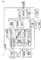
図1は、本実施形態に係る超音波診断装置1の構成例を示すブロック図である。図1に示されるように、超音波診断装置1は、本体装置10、超音波プローブ70、及び位置センサシステム30を具備する。本体装置10は、ネットワーク100を介して外部装置40と接続される。また、本体装置10は、表示機器50および入力装置60と接続される。
FIG. 1 is a block diagram showing a configuration example of the ultrasonic
位置センサシステム30は、超音波プローブ70および超音波画像の3次元の位置情報を取得するためのシステムである。位置センサシステム30は、位置センサ31と位置検出装置32とを含む。
The
位置センサシステム30は、例えば、磁気センサ、赤外線センサまたは赤外線カメラ用のターゲット等を位置センサ31として超音波プローブ70に装着させることで、超音波プローブ70の3次元の位置情報を取得する。なお、超音波プローブ70にジャイロセンサ(角速度センサ)を内蔵させ、このジャイロセンサにより超音波プローブ70の3次元の位置情報を取得してもよい。また、位置センサシステム30は、超音波プローブ70をカメラで撮影し、撮影した画像を画像認識処理することにより超音波プローブ70の3次元の位置情報を取得してもよい。また、位置センサシステム30は、超音波プローブ70をロボットアームで保持し、ロボットアームの3次元空間の位置を超音波プローブ70の位置情報として取得してもよい。
The
なお、以下では、位置センサシステム30が磁気センサを用いて超音波プローブ70の位置情報を取得する場合を例に説明する。具体的には、位置センサシステム30は、例えば磁気発生コイルなどを有する磁気発生器(図示せず)をさらに含む。磁気発生器は、磁気発生器自身を中心として、外側に向かって磁場を形成する。形成された磁場には、位置精度が保証される磁場空間が定義される。よって、磁気発生器の配置は、超音波検査の対象となる生体が、位置精度が保証される磁場空間内に包含されるように配置されればよい。超音波プローブ70に装着される位置センサ31は、磁気発生器によって形成される3次元の磁場の強度および傾きを検出する。これにより、超音波プローブ70の位置と向きとを取得することができる。位置センサ31は、検出した磁場の強度および傾きを位置検出装置32へ出力する。
In the following, a case where the
位置検出装置32は、位置センサ31で検出された磁場の強度および傾きに基づき、例えば、所定の位置を原点とした3次元空間における超音波プローブ70の位置(スキャン面の位置(x、y、z)及び回転角度(θx、θy、θz))を算出する。このとき、所定の位置は、例えば、磁気発生器が配置される位置とする。位置検出装置32は、算出した位置(x、y、z、θx、θy、θz)に関する位置情報を本体装置10へ送信する。
The
なお、上述のように取得した位置情報と超音波プローブ70から送受信された超音波の超音波画像データとを時刻同期などで対応付けることにより、超音波画像データに位置情報を付与することができる。
By associating the position information acquired as described above with the ultrasonic image data of the ultrasonic waves transmitted and received from the
超音波プローブ70は、複数の圧電振動子、圧電振動子に設けられる整合層、及び圧電振動子から後方への超音波の伝播を防止するバッキング材等を有する。超音波プローブ70は、本体装置10と着脱自在に接続される。複数の圧電振動子は、本体装置10が有する超音波送信回路11から供給される駆動信号に基づき超音波を発生する。また、超音波プローブ70には、後述するオフセット処理や、超音波画像のフリーズなどの際に押下されるボタンが配置されてもよい。
The
超音波プローブ70から生体Pに超音波が送信されると、送信された超音波は、生体Pの体内組織における音響インピーダンスの不連続面で次々と反射され、反射波信号として超音波プローブ70が有する複数の圧電振動子にて受信される。受信される反射波信号の振幅は、超音波が反射される不連続面における音響インピーダンスの差に依存する。なお、送信された超音波パルスが、移動している血流や心臓壁などの表面で反射された場合の反射波信号は、ドプラ効果により、移動体の超音波送信方向に対する速度成分に依存して、周波数偏移を受ける。超音波プローブ70は、生体Pからの反射波信号を受信して電気信号に変換する。
When ultrasonic waves are transmitted from the
本実施形態に係る超音波プローブ70は、上述したように、位置センサ31が装着されているので、生体Pを3次元で走査したときの位置情報を検出することが可能である。具体的には、本実施形態に係る超音波プローブ70は、生体Pを2次元で走査する複数の超音波振動子を有する1次元アレイプローブである。なお、位置センサ31が装着される超音波プローブ70は、あるエンクロージャ内に1次元アレイプローブとプローブ揺動用モータを備え、超音波振動子を所定の角度(揺動角度)で揺動させることで煽り走査や回転走査を機械的に行い、生体Pを3次元で走査するメカニカル4次元プローブ(機械揺動方式の3次元プローブ)でもよい。さらに、複数の超音波振動子がマトリックス状に配置される2次元アレイプローブ、又は1次元に配列された複数の振動子が複数に分割される1.5次元アレイプローブであってもよい。
As described above, the
図1に示される本体装置10は、超音波プローブ70が受信した反射波信号に基づいて超音波画像を生成する装置である。本体装置10は、図1に示すように、超音波送信回路11、超音波受信回路12、Bモード処理回路13、ドプラ処理回路14、3次元処理回路15、表示処理回路17、内部記憶回路18、画像メモリ19(シネメモリ)、画像データベース20、入力インタフェース回路21、通信インタフェース回路22および制御回路23を含む。
The main body device 10 shown in FIG. 1 is a device that generates an ultrasonic image based on a reflected wave signal received by the
超音波送信回路11は、超音波プローブ70に駆動信号を供給するプロセッサである。超音波送信回路11は、例えば、トリガ発生回路、遅延回路、及びパルサ回路等により実現される。トリガ発生回路は、所定のレート周波数で、送信超音波を形成するためのレートパルスを繰り返し発生する。遅延回路は、超音波プローブ70から発生される超音波をビーム状に集束して送信指向性を決定するために必要な圧電振動子毎の遅延時間を、トリガ発生回路が発生する各レートパルスに対し与える。パルサ回路は、レートパルスに基づくタイミングで、超音波プローブ70に駆動信号(駆動パルス)を印加する。遅延回路により各レートパルスに対し与える遅延時間を変化させることで、圧電振動子面からの送信方向が任意に調整可能となる。
The
超音波受信回路12は、超音波プローブ70が受信した反射波信号に対して各種処理を施し、受信信号を生成するプロセッサである。超音波受信回路12は、例えば、アンプ回路、A/D変換器、受信遅延回路、及び加算器等により実現される。アンプ回路は、超音波プローブ70が受信した反射波信号をチャンネル毎に増幅してゲイン補正処理を行なう。A/D変換器は、ゲイン補正された反射波信号をデジタル信号に変換する。受信遅延回路は、デジタル信号に受信指向性を決定するのに必要な遅延時間を与える。加算器は、遅延時間が与えられた複数のデジタル信号を加算する。加算器の加算処理により、受信指向性に応じた方向からの反射成分が強調された受信信号が発生する。
The ultrasonic
Bモード処理回路13は、超音波受信回路12から受け取った受信信号に基づき、Bモードデータを生成するプロセッサである。Bモード処理回路13は、超音波受信回路12から受け取った受信信号に対して包絡線検波処理、及び対数増幅処理等を施し、信号強度が輝度の明るさで表現されるデータ(Bモードデータ)を生成する。生成されたBモードデータは、2次元的な超音波走査線上のBモードRAWデータとして不図示のRAWデータメモリに記憶される。
The B-
ドプラ処理回路14は、超音波受信回路12から受け取った受信信号に基づき、ドプラ波形、及びドプラデータを生成するプロセッサである。ドプラ処理回路14は、受信信号から血流信号を抽出し、抽出した血流信号からドプラ波形を生成すると共に、血流信号から平均速度、分散、及びパワー等の情報を多点について抽出したデータ(ドプラデータ)を生成する。
The
3次元処理回路15は、Bモード処理回路13、及びドプラ処理回路14により生成されたデータに基づき、位置情報付きの3次元画像データを生成可能なプロセッサである。位置センサ31が装着されている超音波プローブ70が1次元アレイプローブ、又は1.5次元アレイプローブである場合、3次元処理回路15は、RAWデータメモリに記憶されたBモードRAWデータに対し、位置検出装置32で算出された超音波プローブ70の位置情報を付加する。また、3次元処理回路15は、RAW−ピクセル変換を実行することで、ピクセルから構成される2次元画像データを生成し、生成した2次元画像データに対し、位置検出装置32で算出された超音波プローブ70の位置情報を付加してもよい。
The three-
また、3次元処理回路15は、RAWデータメモリに記憶されたBモードRAWデータに対し、空間的な位置情報を加味した補間処理を含むRAW−ボクセル変換を実行することで、所望の範囲のボクセルから構成される3次元の画像データ(以下、ボリュームデータと称する。)を生成する。ボリュームデータには、位置検出装置32で算出された超音波プローブ70の位置情報が付加される。位置センサ31が装着されている超音波プローブ70がメカニカル4次元プローブ(機械揺動方式の3次元プローブ)、又は2次元アレイプローブの場合も同様に、2次元のRAWデータ、2次元画像データ、及び3次元画像データに位置情報が付加される。
また、3次元処理回路15は、発生したボリュームデータに対してレンダリング処理を施し、レンダリング画像データを生成する。
Further, the three-
Further, the three-
表示処理回路17は、3次元処理回路15において発生された各種画像データに対し、ダイナミックレンジ、輝度(ブライトネス)、コントラスト、γカーブ補正、及びRGB変換等の各種処理を実行することで、画像データをビデオ信号に変換する。表示処理回路17は、ビデオ信号を表示機器50に表示させる。なお、表示処理回路17は、操作者が入力インタフェース回路21により各種指示を入力するためのユーザインタフェース(GUI:Graphical User Interface)を生成し、GUIを表示機器50に表示させてもよい。表示機器50としては、例えば、CRTディスプレイや液晶ディスプレイ、有機ELディスプレイ、LEDディスプレイ、プラズマディスプレイ、又は当技術分野で知られている他の任意のディスプレイが適宜利用可能である。
The
内部記憶回路18は、例えば、磁気的若しくは光学的記録媒体、又は半導体メモリ等のプロセッサにより読み取り可能な記録媒体等を有する。内部記憶回路18は、超音波送受信を実現するための制御プログラム、画像処理を行うための制御プログラム、及び表示処理を行なうための制御プログラム等を記憶している。また、内部記憶回路18は、診断情報(例えば、患者ID、医師の所見等)、診断プロトコル、ボディマーク生成プログラム、及び映像化に用いるカラーデータの範囲を診断部位毎に予め設定する変換テーブル等のデータ群を記憶している。また、内部記憶回路18は、生体内の臓器の構造に関する解剖学図譜、例えば、アトラスを記憶してもよい。
The
また、内部記憶回路18は、入力インタフェース回路21を介して入力される記憶操作に従い、3次元処理回路15で発生された2次元画像データ、ボリュームデータ、レンダリング画像データを記憶する。なお、内部記憶回路18は、入力インタフェース回路21を介して入力される記憶操作に従い、3次元処理回路15で発生された位置情報付きの2次元画像データ、位置情報付きのボリュームデータ、位置情報付きのレンダリング画像データを、操作順番及び操作時間を含めて記憶してもよい。内部記憶回路18は、記憶しているデータを、通信インタフェース回路22を介して外部装置へ転送することも可能である。
Further, the
画像メモリ19は、例えば、磁気的若しくは光学的記録媒体、又は半導体メモリ等のプロセッサにより読み取り可能な記録媒体等を有する。画像メモリ19は、入力インタフェース回路21を介して入力されるフリーズ操作直前の複数フレームに対応する画像データを保存する。画像メモリ19に記憶されている画像データは、例えば、連続表示(シネ表示)される。
The
画像データベース20は、外部装置40から転送される画像データを記憶する。例えば、画像データベース20は、過去の診察において取得された同一患者に関する過去画像データを、外部装置40から取得して記憶する。過去画像データには、超音波画像データ、CT(Computed Tomography)画像データ、MR画像データ、PET(Positron Emission Tomography)−CT画像データ、PET−MR画像データおよびX線画像データが含まれる。
The
なお、画像データベース20は、MO、CD−R、DVDなどの記憶媒体(メディア)に記録された画像データを読み込むことで、所望の画像データを格納してもよい。
The
入力インタフェース回路21は、入力装置60を介して、ユーザからの各種指示を受け付ける。入力装置60は、例えば、マウス、キーボード、パネルスイッチ、スライダースイッチ、トラックボール、ロータリーエンコーダ、操作パネルおよびタッチコマンドスクリーン(TCS)である。入力インタフェース回路21は、例えばバスを介して制御回路23に接続され、操作者から入力される操作指示を電気信号へ変換し、電気信号を制御回路23へ出力する。なお、本明細書において入力インタフェース回路21は、マウス及びキーボード等の物理的な操作部品と接続するものだけに限られない。例えば、超音波診断装置1とは別体に設けられた外部の入力機器から入力される操作指示に対応する電気信号を無線信号として受け取り、この電気信号を制御回路23へ出力する電気信号の処理回路も入力インタフェース回路21の例に含まれる。
The
通信インタフェース回路22は、位置センサシステム30と例えば無線により接続し、位置検出装置32から送信される位置情報を受信する。また、通信インタフェース回路22は、ネットワーク100等を介して外部装置40と接続され、外部装置40との間でデータ通信を行う。外部装置40は、例えば、各種の医用画像のデータを管理するシステムであるPACS(Picture Archiving and Communication System)のデータベース、医用画像が添付された電子カルテを管理する電子カルテシステムのデータベース等である。また、外部装置40は、例えば、X線CT装置、及びMRI(Magnetic Resonance Imaging)装置、核医学診断装置、及びX線診断装置等、本実施形態に係る超音波診断装置1以外の各種医用画像診断装置である。なお、外部装置40との通信の規格は、如何なる規格であっても良いが、例えば、DICOM(digital imaging and communication in medicine)が挙げられる。
The
制御回路23は、例えば、超音波診断装置1の中枢として機能するプロセッサである。制御回路23は、内部記憶回路に記憶されている制御プログラムを実行することで、当該プログラムに対応する機能を実現する。具体的には、制御回路23は、位置情報取得機能101、超音波データ取得機能102、センサ位置合わせ機能103、領域指定機能104、画像位置合わせ機能105および同期制御機能106を実行する。
The
位置情報取得機能101を実行することで、制御回路23は、位置センサシステム30から通信インタフェース回路22を介して超音波プローブ70に関する位置情報を取得する。
By executing the position
超音波データ取得機能102を実行することで、制御回路23は、3次元処理回路15から超音波画像データを取得し、超音波画像データと位置情報とを対応付けて位置情報付き超音波画像データを生成する。
By executing the ultrasonic
センサ位置合わせ機能103を実行することで、位置センサの座標系と医用3D画像データの座標系が関連付けられる。超音波画像データは、位置センサ座標系で位置情報が定義されたのち、位置情報付き超音波画像データと医用3D画像データが位置合わせされる。センサ位置合わせ機能103は、センサ座標系での医用3D画像間の位置合わせ機能である。医用3D画像と超音波3D画像間、あるいは、超音波3D画像間では、自由な向きと位置のデータであることから、画像位置合わせの検索範囲を広くする必要があるが、位置センサの座標系で位置合わせを行うことで、医用3D画像データ間の位置合わせの粗調整を行うことができる。医用3D画像データ間の位置や回転の差異を小さくした状態で、次のステップである画像位置合わせを実施することができる。言い換えると、センサ位置合わせは、医用3D画像間の位置や回転の差異を、画像位置合わせアルゴリズムのキャプチャーレンジ内に抑える役割がある。
By executing the
領域指定機能104を実行することで、制御回路23は、例えば、ユーザからの入力装置60への入力を入力インタフェース回路21を介して受け取り、当該入力に基づいて、超音波画像と医用画像との少なくともいずれか一方において、画像位置合わせの基準となる領域情報を指定する。
By executing the
画像位置合わせ機能105を実行することで、制御回路23は、センサ位置合わせ機能103により対応付けが行われた超音波画像データに基づく超音波画像と前記医用画像データに基づく医用画像との画像位置合わせを行う。
By executing the
同期制御機能106を実行することで、制御回路23は、画像位置合わせが完了したことにより決定される第1座標系と第2座標系との対応関係に基づいて、超音波プローブ70によって新たに取得される超音波画像データに基づく画像であるリアルタイム超音波画像と、リアルタイム超音波画像に対応する前記医用画像データに基づく医用画像とを同期させ、連動して表示させる。
By executing the
位置情報取得機能101、超音波データ取得機能102、センサ位置合わせ機能103、領域指定機能104、画像位置合わせ機能105および同期制御機能106は、制御プログラムとして組み込まれていてもよいし、制御回路23自体または本体装置10に制御回路23が参照可能な回路として、各機能を実行可能な専用のハードウェア回路が組み込まれていてもよい。
The position
制御回路23は、これら専用のハードウェア回路を組み込んだ特定用途向け集積回路(Application Specific Integrated Circuit:ASIC)、フィールド・プログラマブル・ゲート・アレイ(Field Programmable Logic Device:FPGA)、他の複合プログラマブル論理デバイス(Complex Programmable Logic Device:CPLD)、又は単純プログラマブル論理デバイス(Simple Programmable Logic Device:SPLD)により実現されてもよい。
The
次に、超音波診断装置1で収集される超音波画像データの3次元表示(3D表示)および4次元表示(4D表示)について、図2を参照して説明する。なお、図2に示す処理は、3次元処理回路15がおこなってもよいし、制御回路23がおこなってもよい。
図2の上段は超音波データの収集から表示までの流れを各ステップで示し、図2の下段は各ステップで得られるデータの状態を示す。
Next, the three-dimensional display (3D display) and the four-dimensional display (4D display) of the ultrasonic image data collected by the ultrasonic
The upper part of FIG. 2 shows the flow from the collection of ultrasonic data to the display at each step, and the lower part of FIG. 2 shows the state of the data obtained at each step.
ステップS201では、例えば、ユーザが超音波プローブ70を3次元的に走査することにより、3次元の超音波画像データをスタックデータとして収集される。なお、超音波プローブ70として、メカニカル4Dプローブや2次元アレイプローブを用いた電子走査により、3次元的な繰り返し走査が可能となるので、時間的に連続して収集された3次元画像データであって、時間軸を含む4次元の超音波画像データを収集することもできる。
In step S201, for example, the user scans the
ステップS202では、収集されたスタックデータである複数の2次元の超音波画像データ(断層画像)は、それぞれ異なる座標で収集されているため、各断層画像に共通に使用できる座標系を導入する。そのため、等方的なボクセルとして3次元の超音波画像データを再構成(リサンプリング)し、ボリュームデータを得る。 In step S202, since the plurality of two-dimensional ultrasonic image data (tomographic images), which are the collected stack data, are collected at different coordinates, a coordinate system that can be commonly used for each tomographic image is introduced. Therefore, the three-dimensional ultrasonic image data is reconstructed (resampled) as an isotropic voxel to obtain volume data.
ステップS203では、ボリュームデータを、3次元から2次元平面上に投影表示(レンダリング)する。レンダリングの手法としては、例えば、MPR(Multi-Planar Reconstruction/ Reformation)法、VR(Volume Rendering)法およびVR(Volume Rendering)法が挙げられる。 In step S203, the volume data is projected and displayed (rendered) on a three-dimensional to two-dimensional plane. Examples of the rendering method include an MPR (Multi-Planar Reconstruction / Reformation) method, a VR (Volume Rendering) method, and a VR (Volume Rendering) method.
MPR法は、任意方向の断層像を作成する手法であり、指定した断層面近傍のボクセル値を補間することで画素値を求める。MPR法は、通常の超音波撮像では見えない断面を観測できるという点で有用である。通常、立体構造を把握するために、指定断面と当該断面に直交する2断面を合わせた3断面を同時に表示する。 The MPR method is a method of creating a tomographic image in an arbitrary direction, and obtains pixel values by interpolating voxel values in the vicinity of a designated tomographic plane. The MPR method is useful in that it can observe a cross section that cannot be seen by ordinary ultrasonic imaging. Usually, in order to grasp the three-dimensional structure, three cross sections including a designated cross section and two cross sections orthogonal to the cross section are displayed at the same time.
MIP法は、視点と投影面との間の直線上に存在するボクセル値を調べ、その中の最大値を投影面に投影する表示手法である。カラードプラ法による血管像や超音波造影エコー法における造影エコー像の立体描出などに有用である。ただし、MIP法では奥行き情報が消えるため、角度を変えて作成した像を回転させてシネ表示する必要がある。 The MIP method is a display method in which voxel values existing on a straight line between a viewpoint and a projection plane are examined, and the maximum value among them is projected onto the projection plane. It is useful for stereoscopic imaging of blood vessel images by the color Doppler method and contrast-enhanced echo images by the ultrasonic contrast-enhanced echo method. However, since the depth information disappears in the MIP method, it is necessary to rotate the image created by changing the angle and display it in a cine.
VR法は、仮想スクリーンから一様な光が発せられ、発せられた光がボクセル値によって表現される3次元物体によって反射、減衰および吸収されるという仮想的な物理現象をシミュレーションした手法である。スタート点である仮想スクリーン上の点から、一定のステップ間隔で透過光および反射光を更新する。更新処理時に、ボクセル値に応じた不透明度(Opacity)を設定することで、生体の表面から内部構造まで多様な表現ができる。特に微細構造の抽出に優れている。 The VR method is a method of simulating a virtual physical phenomenon in which uniform light is emitted from a virtual screen and the emitted light is reflected, attenuated, and absorbed by a three-dimensional object represented by a voxel value. From the point on the virtual screen that is the starting point, the transmitted light and reflected light are updated at regular step intervals. By setting the opacity according to the voxel value at the time of the update process, various expressions can be made from the surface of the living body to the internal structure. It is particularly excellent in extracting fine structures.
(超音波画像データ間での位置合わせ)
以下では、超音波画像データと医用画像データとの位置合わせ処理として、医用画像データが超音波画像データであり、取得時間が異なる超音波画像データ間の位置合わせ処理について、第一の実施例として、図3のフローチャートを参照して説明する。本実施形態では、例えば、肝臓ガンの治療の場合を想定し、治療前に肝臓ガン周辺の超音波画像データを取得し、治療後に再度、治療された肝臓ガン周辺の超音波画像データを取得し、治療前後の画像を比較して治療効果を判定するような場合を想定する。
(Alignment between ultrasonic image data)
In the following, as the alignment process between the ultrasonic image data and the medical image data, the alignment process between the ultrasonic image data in which the medical image data is the ultrasonic image data and the acquisition time is different will be described as a first embodiment. , Will be described with reference to the flowchart of FIG. In the present embodiment, for example, assuming the case of treatment of liver cancer, the ultrasonic image data around the liver cancer is acquired before the treatment, and the ultrasonic image data around the treated liver cancer is acquired again after the treatment. , Suppose a case where the treatment effect is judged by comparing the images before and after the treatment.
ステップS301では、本実施形態に係る超音波診断装置の超音波プローブ70が操作されることにより、超音波データ取得機能102を実行する制御回路23が、治療対象となる肝臓ガン付近の生体部位(対象部位ともいう)の超音波画像データを取得する。位置情報取得機能101を実行する制御回路23はまた、位置センサシステム30から超音波画像データの取得時における超音波プローブ70の位置情報を取得し、位置情報付き超音波画像データを生成する。
In step S301, the
ステップS302では、制御回路23または3次元処理回路15が、超音波画像データおよび超音波プローブ70の位置情報を用いて、図2に上述した手順により超音波画像データの3次元再構成を行い、位置情報付き超音波画像データのボリュームデータ(第1ボリュームデータともいう)を生成する。なお、治療前の位置情報付き超音波画像データであるため、過去の超音波画像データとして画像データベース20に格納される。
In step S302, the
その後、治療が進んで手術が終了し、治療効果の判定が行われる段階を想定する。
ステップS303では、位置情報取得機能101および超音波データ取得機能102を実行する制御回路23が、ステップS301と同様に、超音波プローブ70および超音波画像データの位置情報を取得する。治療前と同様に、治療後の対象部位に対して超音波プローブ70が操作され、制御回路23が、対象部位の超音波画像データを取得し、位置センサシステムから超音波プローブ70の位置情報を取得し、位置情報付き超音波画像データを生成する。
After that, it is assumed that the treatment progresses, the surgery is completed, and the therapeutic effect is judged.
In step S303, the
ステップS304では、制御回路23または3次元処理回路15が、ステップS302と同様に、取得した超音波画像データおよび位置情報を用いて、位置情報付き超音波画像データのボリュームデータ(第2ボリュームデータともいう)を生成する。
In step S304, the
ステップS305では、センサ位置合わせ機能103を実行する制御回路23が、取得した超音波プローブ70および超音波画像データの位置情報に基づいて、第1ボリュームデータの座標系(第1座標系ともいう)と第2ボリュームデータの座標系(第2座標系ともいう)とを、対象部位の位置が大略合うようにセンサ位置合わせを行う。超音波の第1ボリュームデータの位置も第2ボリュームデータの位置も、共通して位置センサ座標系の記述されている。従って、ボリュームデータに付帯する位置情報で直接位置合わせすることができる。
ステップS306では、第1ボリュームデータの取得から第2ボリュームデータの取得までの間に、生体が動かなければ、センサ位置合わせのみで良好な位置合わせ状態となる。その場合は、図3でステップS308の超音波画像の並列表示を行う。体動などにより、センサ座標系内で位置ずれが発生している場合、ステップS307の画像位置合わせを実施する。位置合わせ結果が良好であれば、ステップS308の超音波画像の並列表示を行う。
画像位置合わせの詳細については、図4を参照して後述する。
In step S305, the
In step S306, if the living body does not move between the acquisition of the first volume data and the acquisition of the second volume data, only the sensor alignment is sufficient to achieve a good alignment state. In that case, the ultrasonic images in step S308 are displayed in parallel in FIG. When the position shift occurs in the sensor coordinate system due to body movement or the like, the image alignment in step S307 is performed. If the alignment result is good, the ultrasonic images in step S308 are displayed in parallel.
Details of image alignment will be described later with reference to FIG.
ステップS308では、制御回路23が、例えば表示処理回路17に指示することにより、治療前である第1ボリュームデータに基づく超音波画像と、治療後である第2ボリュームデータに基づく超音波画像を並列表示する。以上で超音波画像データ間の位置合わせ処理を終了する。
In step S308, the
次に、ステップS307に示す画像位置合わせ機能が実現する制御回路23による画像位置合わせ処理について図4のフローチャートを参照して説明する。
ステップS401では、制御回路23が、第1ボリュームデータと第2ボリュームデータのうちの一方に関して、ここでは第2ボリュームデータに関して、座標を変換する。例えば、対象となる画像データに対して最低、X方向、Y方向、Z方向の回転と平行移動の6つのパラメータ、必要であれば3つのせん断方向も含めた9つのパラメータで座標変換すればよい。
Next, the image alignment process by the
In step S401, the
ステップS402では、制御回路23が、座標変換された領域をチェックする。具体的には、例えば、ボリュームデータ領域外のデータを除外する。領域内を1、領域外をゼロで表した配列を同時に生成してもよい。また、領域外を特定の画素値(例えば255)に設定し、輝度を0〜254により表現してもよい。
In step S402, the
ステップS403では、制御回路23が、第1ボリュームデータと第2ボリュームデータとの類似度に関する特徴量を計算する。例えば、ボクセルの輝度値などを特徴量として計算する。
In step S403, the
ステップS404では、制御回路23が、第1ボリュームデータと第2ボリュームデータとの位置ずれの評価関数を計算する。評価関数としては、例えば、ステップS403で算出した輝度値の輝度差分、相互相関、または、ボリュームデータ間の輝度の構造情報をあわせた後に類似度が最も高い領域を探索する等の相互情報量を用いればよい。
In step S404, the
ステップS405では、制御回路23が、評価関数が最適値基準を満たすかどうかを判定する。最適値基準を満たす場合、ステップS406に進み、最適値基準を満たさない場合、ステップS406に進む。最適値基準を満たすかどうかは、類似度の基準の向上をそれ以上望めなくなった時点で最適値基準を満たすとすればよい。
In step S405, the
ステップS406では、制御回路23が、最適値基準の結果に応じて、変換パラメータを変更する。類似度の基準値の向上が望めなくなった場合、局所解に陥っている可能性がある。当然のことながら、このときの類似度基準は最適解のそれよりも小さく、大きく位置がずれているときの画像の類似度基準との比を、経験的にわかっている最適解時のそれと比較することで判定することができる。もし、局所解に陥っていると判断した場合、その位置より、パラメータを少し変更して最適化を再度実行することで最適解に収束することが期待できる。パラメータの変更は、例えばdownhill、symplex法の場合であれば、初期設定するシンプレックスの位置を前回より大きくするなどで対応する。
In step S406, the
ステップS407では、位置ずれ量を決定し、位置ずれ量の分だけ補正する。以上で画像位置合わせ処理を終了する。なお、図4に示す画像位置合わせは一例であり、画像位置合わせに関する一般的な手法を用いてもよい。 In step S407, the amount of misalignment is determined and corrected by the amount of misalignment. This completes the image alignment process. The image alignment shown in FIG. 4 is an example, and a general method for image alignment may be used.
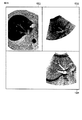
図3により説明してきた超音波3D画像データ間の位置合わせの一例を、図5に示す。 図5の左側の画像が治療前の第1ボリュームデータに基づく超音波画像であり、図5の右側の画像が治療後の第2ボリュームデータに基づく超音波画像である。図3のステップS305の状態にある。なお以下では、超音波画像は白黒反転表示で図示する。図5に示すように、超音波画像データを取得する時期が異なれば、同一の対象部位を走査した場合でも、体動などが原因で位置ずれが生じうる。 An example of the alignment between the ultrasonic 3D image data described with reference to FIG. 3 is shown in FIG. The image on the left side of FIG. 5 is an ultrasonic image based on the first volume data before the treatment, and the image on the right side of FIG. 5 is an ultrasonic image based on the second volume data after the treatment. It is in the state of step S305 of FIG. In the following, the ultrasonic image is shown in black-and-white inverted display. As shown in FIG. 5, if the timing of acquiring the ultrasonic image data is different, even if the same target site is scanned, the position shift may occur due to body movement or the like.
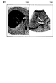
次に、ステップS308に示す画像位置合わせ後の超音波画像表示の一例について図6を参照して説明する。
図6の左側の画像が治療前の第1ボリュームデータに基づく超音波画像であり、図6の右側の画像が治療後の第2ボリュームデータに基づく超音波画像である。図6に示すように、治療前後の超音波画像データが位置合わせされ、第1ボリュームデータに基づく超音波画像が第2ボリュームデータに基づく超音波画像の位置に合わせて回転して並列表示される。図6のように、超音波画像間で位置合わせが完了しているので、ユーザはパネル操作などで、所望の断面を位置合わせした状態で検索して表示でき、対象部位の評価(治療部位の治療状態)を容易に把握することができる。
Next, an example of the ultrasonic image display after the image alignment shown in step S308 will be described with reference to FIG.
The image on the left side of FIG. 6 is an ultrasonic image based on the first volume data before the treatment, and the image on the right side of FIG. 6 is an ultrasonic image based on the second volume data after the treatment. As shown in FIG. 6, the ultrasonic image data before and after the treatment are aligned, and the ultrasonic image based on the first volume data is rotated and displayed in parallel according to the position of the ultrasonic image based on the second volume data. .. As shown in FIG. 6, since the alignment between the ultrasonic images is completed, the user can search and display the desired cross section in the aligned state by operating the panel or the like, and evaluate the target site (treatment site). The treatment status) can be easily grasped.
(体動や呼吸時相による位置ずれの補正)
第2の実施例を、図7にて説明する。
(Correction of misalignment due to body movement and respiratory phase)
A second embodiment will be described with reference to FIG.
治療中において体動により、超音波画像データ間で位置センサ座標系で大きな位置ずれが発生し、画像位置合わせでの補正可能な範囲を超えることがある。磁場強度の維持の観点で、磁場の送信機を患部に近い場所に移動させることもある。そのようなケースでは、センサ位置合わせ機能103により、センサの座標系を対応付けた後も、超音波画像データ間に大きな位置ずれが残存する場合も想定される。そのようなケースに対して、第2の実施例として図7のフローチャートがある。ユーザは、ステップS306でセンサ位置合わせ後も大きな位置ずれありと判断し、ステップS701のプロセスを行う。
During treatment, body movement may cause a large displacement in the position sensor coordinate system between the ultrasound image data, which may exceed the correctable range for image alignment. From the viewpoint of maintaining the magnetic field strength, the magnetic field transmitter may be moved to a place closer to the affected area. In such a case, it is assumed that a large positional deviation remains between the ultrasonic image data even after the coordinate system of the sensor is associated with the
ユーザが、第1ボリュームデータに基づく超音波画像と第2ボリュームデータに基づく超音波画像との間で対応する生体部位を示す対応点を、それぞれの超音波画像において指定する。対応点の指定方法は、例えば、表示処理回路17が生成したユーザインタフェースにより、ユーザが操作パネルを用いて画面に表示されるカーソルを動かし、対応点を指定してもよいし、タッチスクリーンであれば、直接画面上で対応点をタッチしてもよい。図8の例では、ユーザによって、第1ボリュームデータに基づく超音波画像上の対応点801が指定され、第2ボリュームデータに基づく超音波画像上で、対応点801に対応する対応点802が指定される。制御回路23は、指定された対応点801及び対応点802を、例えば「+」のマークで表示させる。これによって、ユーザは対応点を容易に把握することができ、ユーザに対して対応点の入力を支援することができる。領域指定機能104を実行する制御回路23は、それぞれ指定された対応点801間の位置ずれを計算し、位置ずれを補正する。位置ずれの補正は、例えば、対応点801と対応点802との相対距離をずれ量として計算し、ずれ量の分、第2ボリュームデータに基づく超音波画像を移動および回転させればよい。
The user specifies in each ultrasonic image a corresponding point indicating a corresponding biological part between the ultrasonic image based on the first volume data and the ultrasonic image based on the second volume data. As a method of designating the corresponding points, for example, the user may move the cursor displayed on the screen by using the operation panel by the user interface generated by the
なお、対応する生体部位における所定範囲の領域を対応領域として指定してもよく、対応領域が指定される場合でも対応点の場合と同様に処理すればよい。
さらに、体動や呼吸時相による位置ずれを補正する例を示したが、ユーザが画像位置合わせにおける関心領域(ROI)を指定するために、対応点または対応領域を指定してもよい。
A predetermined range of a region in the corresponding biological part may be designated as the corresponding region, and even when the corresponding region is designated, it may be processed in the same manner as in the case of the corresponding point.
Further, although an example of correcting the positional deviation due to the body movement or the respiratory phase is shown, the corresponding point or the corresponding area may be specified in order for the user to specify the region of interest (ROI) in the image alignment.
図7のステップS702により超音波画像間の位置ずれが補正された後、第1の実施形態と同様に、ユーザは画像位置合わせの指示を、例えば操作パネルによりまたは超音波プローブ70に取り付けられるボタンを押下することにより指示する。図7のステップS703の画像位置合わせ機能は、位置ずれが補正された超音波画像データに基づいて、画像位置合わせを行えばよい。図3のフローチャートと同様に、図6に示した状態になる。
画像位置合わせの指示があった後、表示処理回路17は、図7のステップS308にて位置合わせした超音波画像を並列表示させる。これにより、ユーザは超音波診断装置の操作パネルなどで画像の位置や向きを自由に変更して観察することができる、超音波3D画像データは、第1ボリュームデータと第2ボリュームデータの位置関係が連結され、MPR断面が同期して移動・回転することができる。必要により、同期を解除して独立に観察することもできる。超音波診断装置の操作パネルに変えて、超音波プローブ70をMPR断面の移動や回転のユーザインタフェースにすることもできる。超音波プローブ70には磁気センサが設置されており、超音波システムは超音波プローブ70の動き量・回転量・向きを検出できる。超音波プローブ70の動きで、超音波3D画像データの第1ボリュームデータと第2ボリュームデータとの位置を同期させて移動・回転させることができる。
After the misalignment between the ultrasonic images is corrected by step S702 in FIG. 7, the user gives an image alignment instruction, for example, by an operation panel or a button attached to the
After receiving the image alignment instruction, the
(超音波画像データと超音波画像以外の医用画像データとの間の位置合わせ)
第3の実施例を、説明する。
以下では、CT画像データ、MR画像データ、X線画像データ、PET画像データなどの他のモダリティにより得られた医用画像データと超音波プローブ70を用いて現在取得される超音波画像データとの間の位置合わせを行う場合について説明する。なお、以下では医用画像データとしてMRI画像データを用いる場合を想定する。
(Alignment between ultrasonic image data and medical image data other than ultrasonic images)
A third embodiment will be described.
In the following, between the medical image data obtained by other modalities such as CT image data, MR image data, X-ray image data, PET image data, and the ultrasonic image data currently acquired using the
超音波画像データと医用画像データとの位置合わせ処理について、図9のフローチャートを参照して説明する。なお、医用画像データとして3次元画像データを想定するが、必要に応じて、4次元画像データを医用画像データとしてもよい。 The alignment process of the ultrasonic image data and the medical image data will be described with reference to the flowchart of FIG. Although three-dimensional image data is assumed as the medical image data, the four-dimensional image data may be used as the medical image data if necessary.
ステップS901では、制御回路23が、画像データベース20から医用3D画像データを読み出す。
ステップS902では、位置センサシステム30のセンサ座標系と医用3D画像データの座標系との対応付けを行う。
ステップS903では、位置情報取得機能101および超音波データ取得機能102を実行する制御回路23が、超音波プローブ70で取得される位置情報と超音波画像データと、超音波画像データを取得したときの位置情報とを対応付けて位置情報付き超音波画像データとして取得する。
In step S901, the
In step S902, the sensor coordinate system of the
In step S903, when the
ステップS904では、位置情報付き超音波画像データのボリュームデータを生成する。
ステップS905では、画像位置合わせ機能105を実行する制御回路23が、ステップS307と同様にボリュームデータと医用3D画像データとの間で画像位置合わせを行う。
ステップS906では、表示処理回路17が、ボリュームデータに基づく超音波画像と医用3D画像データに基づく医用画像とを並列表示する。
In step S904, volume data of ultrasonic image data with position information is generated.
In step S905, the
In step S906, the
次に、ステップS902に示すセンサ座標系と医用3D画像データの座標系との対応付けについて、図10Aから図10Cを参照して説明する。図3のフローチャートのステップS306に相当するセンサ位置合わせのプロセスである。 Next, the correspondence between the sensor coordinate system shown in step S902 and the coordinate system of the medical 3D image data will be described with reference to FIGS. 10A to 10C. This is a sensor alignment process corresponding to step S306 in the flowchart of FIG.
図10Aは初期状態を表しており、図10Aに示すように、超音波画像データに付加される位置情報を生成するための位置センサシステムの位置センサ座標系1001と、医用画像データの医用画像座標系1002とが、独立して定義される。
図10Bは、それぞれの座標系の軸合わせのプロセスを示している。位置センサ座標系1001の座標軸と医用画像座標系1002の座標軸とが同一の方向となるように揃える。すなわち、座標系の座標軸の向きを揃える。
図10Cは、目印合わせのプロセスである。位置センサ座標系1001と医用画像座標系1002との座標を所定の基準点に従って合わせた場合を示し、座標系間で軸の向きだけでなく、座標の位置も一致させることができる。
FIG. 10A shows an initial state, and as shown in FIG. 10A, the position sensor coordinate
FIG. 10B shows the process of aligning the axes of each coordinate system. The coordinate axes of the position sensor coordinate
FIG. 10C is a mark matching process. The case where the coordinates of the position sensor coordinate
センサ座標系と医用3D画像データの座標系との対応付けの実際の装置上で実現するプロセスについて、図11Aおよび図11Bを参照して説明する。
図11Aは、医師が肝臓の検査を行う場合の例の模式図を示している。医師は、超音波プローブ70を患者の腹部に水平方向に設置する。CTやMRのアキシャル(Axial)画像と同じ向きの超音波断層像が得られるように、超音波プローブ70は体軸に垂直で、かつ超音波断層像がお腹側から背中に向かって鉛直に設置する。これにより、図11Bのような画像が得られる。本実施例では、ステップS901で画像データベース20より3次元MR画像データを読み込み、モニタの左側に表示される3次元MR画像である。アイコン1101の位置で得られるアキシャル断面のMR画像が、図11Bに示すMR画像1102であり、モニタの左側に表示される。さらに、モニタの右側には、MR画像1102に並列して、そのときのリアルタイムに更新されるリアルタイム超音波画像1103が表示される。図11Aのように超音波プローブ70を腹部に設置することにより、MRのAxial面と同じ向きの超音波断層像が得られる。
The process of associating the sensor coordinate system with the coordinate system of the medical 3D image data on an actual device will be described with reference to FIGS. 11A and 11B.
FIG. 11A shows a schematic diagram of an example when a doctor performs a liver examination. The doctor places the
ユーザは、超音波プローブ70をアキシャル断面の方向で生体の体表に当接する。超音波プローブ70がアキシャル断面の方向となっているかどうかは、ユーザが、目視により確認する。ユーザがアキシャル断面の方向に超音波プローブ70を生体に当接した場合に、操作パネルによるクリックや、ボタンを押下するなどの登録処理を行うことで、制御回路23は、この状態の超音波プローブ70のセンサの位置情報のセンサ座標とMRデータのMPR面の位置のMRデータ座標とを取得して関連づける。生体のMR画像データにおけるアキシャル断面を位置センサ座標に変換して認識することができる。これによって、図11Bで示した軸合わせ(座標系の座標軸の向きの一致)が完了する。システムは、軸合わせの状態で、MRのMPR像とリアルタイムの超音波断層像をセンサ座標で関連付けて、連動させて表示することができる。このとき、両座標系の軸は合っているので画像の向きは合うが、体軸方向の位置にずれが残っている。ユーザは、体軸方向の位置にずれがある状態で、超音波プローブ70を動かすことで、MRのMPR面とリアルタイムの超音波像を連動して観察することができる。
The user abuts the
次に、図11Cで示した目印合わせのプロセスの装置での実現の方法を、図12を参照して説明する。
図12は、モニタに表示される、図11Bに示すMR画像1102およびリアルタイム超音波画像1103の並列表示画面である。
Next, a method of realizing the mark matching process shown in FIG. 11C with an apparatus will be described with reference to FIG.
FIG. 12 is a parallel display screen of the
軸合わせが完了したのち、ユーザは、体軸方向の位置にずれがある状態で、超音波プローブ70を動かすことで、MRのMPR面とリアルタイムの超音波像とを連動して観察することができる。
ユーザは、モニタに表示されるリアルタイム超音波画像1103を見ながら、超音波プローブ70を走査することにより位置合わせをする領域の中心または構造物などの対象部位(またはROI)をモニタに表示させる。その後、ユーザは、操作パネルなどにより対象部位を対応点1201として指定する。図12の例では、指定された対応点を、「+」で示す。この時、システムは対応点1201のセンサ座標系の位置情報を取得して記録する。
After the axis alignment is completed, the user can observe the MPR surface of the MR and the real-time ultrasonic image in conjunction with each other by moving the
While viewing the real-time
次に、ユーザは、超音波プローブ70を動かすことでMRのMPR断面を動かし、ユーザにより指定された超音波画像の対応点1201を含む断面に対応するMR画像の断面像を表示する。対応点1201を含む断面に対応するMR画像の断面像が表示された場合、ユーザは、MR画像の断面像において指定された位置合わせをする領域の中心または構造物などの対象部位(またはROI)を、操作パネルなどにより対応点1202として指定する。この時、システムは対応点1201のMRデータの座標系の位置情報を取得して記録する。
Next, the user moves the MPR cross section of the MR by moving the
領域指定機能を実行する制御回路23は、指定された対応点のセンサ座標系での位置とMRデータの座標系での位置に基づいて、MR画像データの座標系とセンサ座標系との位置ずれを補正する。具体的には、例えば、対応点1201と対応点1202との差分に基づいて、MR画像データの座標系とセンサ座標系のずれを補正して、座標系の位置合わせを行う。これにより、図10Cの目印合わせのプロセスが完了し、図9のフローチャートのステップS902のステップが完了する。
The
次に、図9のフローチャートのS903のステップである、MRデータの座標系とセンサ座標系の位置合わせがされた状態での超音波画像データの収集例について図13の模式図にて説明する。
ユーザは、位置補正が完了したのち、3次元MR画像データを参照しながら、対象部位を含む領域について超音波プローブ70を用手的に操作して、位置情報付き超音波画像データを収集する。図13には、ユーザが腹部で超音波プローブ70を用手的に動かす模式図を示す。
Next, an example of collecting ultrasonic image data in a state where the coordinate system of MR data and the sensor coordinate system are aligned, which is the step of S903 in the flowchart of FIG. 9, will be described with reference to the schematic diagram of FIG.
After the position correction is completed, the user manually operates the
次に、ユーザは、画像位置合わせのスイッチを押下して、画像位置合わせを行う。これまでのプロセスで、MRデータと超音波データの位置は概ね一致しており、両者に共通する対象を含んでいるので、画像位置合わせが良好に動作する。画像位置合わせ後の超音波画像表示の一例について図14を参照して説明する。図9のステップS906のとおり、MR画像と位置合わせされた超音波画像は、並列に表示される。
図14に示すように、画像位置合わせに応じて、超音波画像データの超音波画像1401が、MR3D画像データのMR3D画像1402に対応するように観点して表示される。よって、超音波画像とMR3D画像との位置関係が把握しやすくなる。超音波診断装置の操作パネルなどで画像の位置や向きを自由に変更して観察することができる、MR3Dデータと超音波3D画像データは、位置関係が連結され、MPR断面が同期して移動・回転することができる。必要により、同期を解除して独立に観察することもできる。超音波診断装置の操作パネルに変えて、超音波プローブ70をMPR断面の移動や回転のユーザインタフェースにすることもできる。超音波プローブ70には磁気センサが設置されており、超音波システムは超音波プローブ70の動き量・回転量・向きを検出できる。超音波プローブ70の動きで、MR3Dデータと超音波3D画像データとの位置を同期させて移動・回転させることができる。
Next, the user presses the image alignment switch to perform image alignment. In the process so far, the positions of the MR data and the ultrasonic data are almost the same, and since they include an object common to both, the image alignment works well. An example of ultrasonic image display after image alignment will be described with reference to FIG. As shown in step S906 of FIG. 9, the ultrasonic image aligned with the MR image is displayed in parallel.
As shown in FIG. 14, the
第三の実施例において、MR3Dデータを例に説明を行ったが、CT・X線・超音波・PET等の医用3D画像データに同様に適用できる。医用3Dデータの座標系と位置センサの座標系の関連付けは、図10A〜図10Cに示した軸合わせと目印合わせとのステップにて説明したが、座標間の位置合わせは、様々な手法で可能である。両座標で3点以上を指定して、位置を合わせるなど、他の方法を持ちうることも可能である。さらに、位置ずれの補正が完了した後に位置情報付き超音波画像データを収集する代わりに、位置ずれの補正前に位置情報付き超音波画像データを取得してボリュームデータを生成し、超音波画像データのボリュームデータに基づく超音波画像と医用3D画像データに基づく医用画像との間で対応点を指定し、位置ずれの補正をしてもよい。 In the third embodiment, MR3D data has been described as an example, but it can be similarly applied to medical 3D image data such as CT, X-ray, ultrasonic wave, and PET. The association between the coordinate system of the medical 3D data and the coordinate system of the position sensor was explained in the steps of axis alignment and mark alignment shown in FIGS. 10A to 10C, but the alignment between the coordinates can be performed by various methods. Is. It is also possible to have other methods such as specifying three or more points with both coordinates and aligning the positions. Further, instead of collecting the ultrasonic image data with the position information after the correction of the misalignment is completed, the ultrasonic image data with the position information is acquired and the volume data is generated before the correction of the misalignment, and the ultrasonic image data is generated. Corresponding points may be specified between the ultrasonic image based on the volume data of the above and the medical image based on the medical 3D image data, and the misalignment may be corrected.
(超音波画像と医用画像との同期表示)
第四の実施例を示す。
(Synchronous display of ultrasound images and medical images)
A fourth embodiment is shown.
上述したセンサ位置合わせおよび画像位置合わせが完了すると、医用画像の座標系(ここではMR座標系)と位置センサ座標系との対応関係が決定される。表示処理回路17は、位置合わせ処理が完了した後にユーザが自由に超音波プローブ70を動かして得られるリアルタイム(ライブ)の超音波画像の位置情報を参照して、対応するMRのMPR断面を表示することができる。高精度に位置合わせが行われたMR画像とリアルタイムの超音波画像との対応断面を連動させて表示(同期表示ともいう)させることができる。
超音波3D画像間でも同様の手法で同期表示することができる。すなわち、過去に取得した超音波3D画像とリアルタイムの超音波3D画像とについて同期表示させることができる。図3と図7のステップS308のステップ、および図9のステップS906のステップにて、医用3D画像と位置合わせされた超音波3D画像の並列の同期表示を例示してきたが、センサ座標を利用して、リアルタイムの超音波断層像を切り替えて表示することが可能である。
When the above-mentioned sensor alignment and image alignment are completed, the correspondence between the coordinate system of the medical image (here, the MR coordinate system) and the position sensor coordinate system is determined. The
Synchronous display can be performed between ultrasonic 3D images by the same method. That is, the ultrasonic 3D image acquired in the past and the real-time ultrasonic 3D image can be displayed in synchronization. In steps S308 of FIGS. 3 and 7 and step S906 of FIG. 9, the parallel synchronous display of the ultrasonic 3D image aligned with the medical 3D image has been illustrated, but the sensor coordinates are used. It is possible to switch and display real-time ultrasonic tomographic images.
超音波画像と医用画像との同期表示の一例を図15に示す。例えば、超音波プローブ70を走査すると、リアルタイムの超音波画像1501と、対応するMR3D画像1502と、位置合わせに用いた位置合わせ用超音波画像1503とが表示される。なお、図16に示すように、位置合わせ用超音波画像1503を表示させず、リアルタイムの超音波画像1501とMR3D画像1502とを並列表示してもよい。
FIG. 15 shows an example of synchronous display of an ultrasonic image and a medical image. For example, when the
第五の実施例を示す。
図17のフローチャートが示すとおり、超音波3Dデータの取得の後に、センサ座標と医用3D画像データのデータ座標の関連づけを行っても良い。例えば、図17のフローチャートのステップS1701およびステップS1702は、図18に示すように、超音波データ取得機能を実行する制御回路23は、3次元超音波データを読み込み、モニタの右側に超音波3D画像1801を表示させる。制御回路23は、画像データベースから医用3D画像データの医用3D画像1802(ここでは、3次元CT画像データ)を読み込み、モニタの左側に表示する。
A fifth embodiment is shown.
As shown in the flowchart of FIG. 17, after the acquisition of the ultrasonic 3D data, the sensor coordinates and the data coordinates of the medical 3D image data may be associated with each other. For example, in steps S1701 and S1702 of the flowchart of FIG. 17, as shown in FIG. 18, the
図17のフローチャートのステップS1703は、図18では、領域指定機能を実行する制御回路23は、3次元CT画像の断面と超音波画像の断面とに対して領域情報、ここでは対応点または対応領域を指定する。図18では、「+」の印で指定場所を表示している。なお、対応点または対応領域ではなく、画像位置合わせの計算を行う際の領域を指定させることもできる。
領域指定機能104を実行する制御回路23は、MRのデータ座標での対応点の座標と位置センサ座標での対応点の座標とを関連づけて、センサ位置合わせを行う。
In step S1703 of the flowchart of FIG. 17, in FIG. 18, the
The
画像位置合わせ機能105を実行する制御回路23は、領域情報に基づいて、超音波画像と医用画像との画像位置合わせを行う。ユーザは、センサ位置合わせがされた状態で、画像位置合わせを例えば、操作パネルより指示する。対応領域に基づいて3次元CT画像データと3次元超音波データを読み込み、画像位置合わせアルゴリズムによる処理を行う。
The
図19は、画像位置合わせ処理後の画像の表示例を示す。図19に示すように、超音波3D画像1801の位置に合わせて医用3D画像1802が回転して表示される。また、図20も、画像位置合わせ処理後の画像の表示例であるが、3次元CT画像と超音波3D画像との対応する断面が重ね合わせ表示2001として表示される。
FIG. 19 shows an example of displaying an image after the image alignment process. As shown in FIG. 19, the
以上に示した本実施形態によれば、位置センサシステムにより位置情報が付加された超音波プローブ70を走査して得られる超音波画像データに基づいて、取得時期、取得場所が異なる超音波画像データを含む医用画像間の座標系の対応付けを行い、対応付けに基づいて画像位置合わせを行うことで、画像位置合わせの成功率が高まり、簡便で正確な位置合わせが行われた超音波画像と医用画像とをユーザに提示することができる。また、画像位置合わせが完了したセンサ座標系と医用画像の座標系とを間に同期が取れているため、超音波プローブ70の走査に連動して医用3D画像のMPR断面とリアルタイムの超音波断層像を同期して表示することができる。医用画像と超音波画像との正確な比較が実現され、超音波診断の客観性を向上させることができる。
According to the present embodiment shown above, the acquisition time and the acquisition location are different from the ultrasonic image data based on the ultrasonic image data obtained by scanning the
これまで記述した本実施例では、位置センサシステムとして磁気センサを利用した位置センサシステムを例示した。
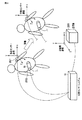
図21には、位置センサシステムとして、赤外線を利用した場合の実施例を示す。赤外線発生器2102より赤外線が少なくとも2方向より送信される。超音波プローブ70に設置されたマーカー2101により赤外線が反射される。反射した赤外線を赤外線発生器2102が受信して、データが位置センサシステム30に送信される。位置センサシステム30は、複数方向から観察された赤外線情報よりマーカーの位置と向きを検出して、超音波診断装置に位置情報を送信する。
In the present embodiment described so far, a position sensor system using a magnetic sensor has been exemplified as the position sensor system.
FIG. 21 shows an embodiment when infrared rays are used as the position sensor system. Infrared rays are transmitted from the
図22には、位置センサシステムとして、ロボットアームを利用した場合の実施例を示す。ロボットアーム2201が、超音波プローブ70を動かす。あるいは、超音波プローブ70にロボットアーム2201が装着された状態で医師が超音波プローブ70を動かす。ロボットアーム2201には位置センサが取り付けられており、ロボットアーム制御部2202にロボットアーム各所の位置情報が逐次送信される。ロボットアーム制御部2202は、超音波プローブ70の位置情報に変換して、超音波診断装置に送信する。
FIG. 22 shows an embodiment when a robot arm is used as the position sensor system. The
図23には、位置センサシステムとして、ジャイロセンサを利用した場合の実施例を示す。ジャイロセンサ2301が、超音波プローブ70に内蔵されるか、超音波プローブ70表面に設置される。ジャイロセンサ2301よりケーブルにより位置情報が、位置センサシステム30に送信される。ケーブルは、超音波プローブ70用のケーブルの一部を使用するか、専用のケーブルを使うことがある。位置センサシステム30も、専用のユニットの場合と、超音波装置内のソフトウエアで実現する場合もある。ジャイロセンサでは、所定の初期位置に対して、加速度や回転情報を積分して、位置と向きの変化を検出することができる。GPS情報により、位置を補正することも考えられる。あるいは、ユーザの入力により、初期位置設定や補正を行うことができる。位置センサシステム30により、ジャイロセンサの情報が積分処理などにより位置情報に変換され、超音波診断装置に送信される。
FIG. 23 shows an embodiment when a gyro sensor is used as the position sensor system. The
図24には、位置センサシステムとして、カメラを利用した場合の実施例を示す。カメラ2401より超音波プローブ70周辺が複数方向より撮影される。撮影された画像は画像記録解析部2403に送られ、超音波プローブ70を自動認識して位置を計算する。撮像制御部2402は、計算された位置を超音波プローブ70の位置情報として、超音波診断装置に送信する。
FIG. 24 shows an embodiment when a camera is used as the position sensor system. The area around the
(センサ位置合わせ部の変形例)
図1に示したセンサ位置合わせ機能には、様々な実施形態がある。第1の実施例から第4の実施例までの説明で述べられているが、その形態を改めて記述し、さらに変形例を述べる。
(Modification example of sensor alignment part)
The sensor alignment function shown in FIG. 1 has various embodiments. Although it has been described in the description from the first embodiment to the fourth embodiment, the form thereof will be described again, and a modified example will be further described.
本実施形態に係るセンサ位置合わせ部は、様々な実施形態がある。センサ位置合わせ部の第1の実施例は、医用3D画像データの位置合わせ対象領域を、超音波プローブ70を動かして超音波画像で描出して、その超音波画像の位置センサ座標と対応する医用3D画像データの座標を関連づける。図9のフローチャートや図12で説明を行った。
The sensor alignment unit according to this embodiment has various embodiments. In the first embodiment of the sensor alignment unit, the alignment target area of the medical 3D image data is visualized as an ultrasonic image by moving the
センサ位置合わせ部の第2の実施例は、医用3D画像データが位置センサの位置情報付き超音波3D画像データの場合である。センサ位置合わせ部は、共通の位置センサ座標を利用して関連づけることが、図3のフローチャートに示されている。図25に磁気センサによる位置センサシステムの模式図を示す。例えば、磁気の送信機2501に磁場空間の座標を定義する。この送信機座標で超音波プローブ70に装着された超音波プローブ用磁気センサ2502の位置が定義できる。
超音波プローブ70を動かして超音波3D画像データを取得する場合、共通の送信機座標で超音波3D画像データ間の位置や向きの関係を把握して、位置合わせを行うことができる。
The second embodiment of the sensor alignment unit is a case where the medical 3D image data is ultrasonic 3D image data with position information of the position sensor. It is shown in the flowchart of FIG. 3 that the sensor alignment unit is associated with each other by using the common position sensor coordinates. FIG. 25 shows a schematic diagram of a position sensor system using a magnetic sensor. For example, a
When the
センサ位置合わせ部の第3の実施例は、体表にもう一つの磁気センサを設置するケースである。図26に、超音波検査中に生体が移動した場合の模式図を示す。磁場の空間は、送信機座標系であり、生体の移動により超音波プローブ70の位置が変化する。しかしながら、生体と超音波プローブ70の位置関係に変化がないことがあり得る。その場合、第二の実施例のとおりに、共通の送信機座標で超音波3D画像データ間の位置合わせを行うと、生体の移動分のずれが発生する。図27に、体表にもう一つの磁気センサ2701を設置し、体表の磁気センサ2701を原点とする磁場空間の座標系を定義する。図26のように生体が動いても、図27に示すとおり、体表の磁気センサ2701を原点とする体表センサ座標では、生体の動きの影響を除去することができる。図27のとおり、体表センサ座標を共通の座標系として、超音波3D画像データ間の位置や向きの関係を把握して、位置合わせを行うことができる。
A third embodiment of the sensor alignment unit is a case where another magnetic sensor is installed on the body surface. FIG. 26 shows a schematic diagram when the living body moves during the ultrasonic examination. The space of the magnetic field is the transmitter coordinate system, and the position of the
図22に示した位置センサシステムとして用いられるロボットアームは、1台に限定されない。位置センサシステムは、第2のロボットアームを備えてもよい。第2のロボットアームは、例えば、生体Pの体表における指定された点を追従するように制御される。ロボットアーム制御部(図示せず)は、第2のロボットアームの位置を把握しながら、第2のロボットアームの移動を制御する。制御回路23は、第2のロボットアームが追従する位置を生体の指定された点であると認識する。なお、指定された点が体内に存在する場合には、第2のロボットアームが追従する位置と、超音波断層画像内の指定部位の位置とから、指定された点の位置を算出する。これにより、生体Pが検査中に動いた場合、及び検査中に生体Pの体位を変更する必要が生じた場合においても、継続して生体対象部位を認識し続けることが可能となる。
The number of robot arms used as the position sensor system shown in FIG. 22 is not limited to one. The position sensor system may include a second robot arm. The second robot arm is controlled to follow a designated point on the body surface of the living body P, for example. The robot arm control unit (not shown) controls the movement of the second robot arm while grasping the position of the second robot arm. The
(超音波画像データの変形例)
ここまで、超音波画像データとして、位置情報付きの超音波3D画像データを例示してきた。しかしながら、超音波画像データは、位置情報付きの2D断層像であっても良い。
図4の画像位置あわせ処理の流れにおいて、例えば、Volume2を2D断層像にすることができる。Volume1を位置情報付き超音波3D画像データとして、Volume2の2D断層像を座標変換でVolume1と重なる領域を変えながら類似度を評価する。位置ずれ評価関数が基準を満たした段階で位置合わせを終了し、Volume1の位置情報付き超音波3D画像データとVolume2の2D断層像の位置関係が決定される。
(Modification example of ultrasonic image data)
Up to this point, ultrasonic 3D image data with position information has been illustrated as ultrasonic image data. However, the ultrasonic image data may be a 2D tomographic image with position information.
In the flow of the image alignment process of FIG. 4, for example, Volume 2 can be made into a 2D tomographic image. Using
超音波画像データは、位置情報付きの機械揺動式の4Dプローブ(メカニカル4Dプローブ)か、2Dアレイプローブによる電子走査により収集された超音波3D画像データ、あるいは超音波4D画像データでも良い。図28には、2Dアレイプローブに位置センサを設置した実施例を示す。図1に示した第一の実施例では、用手的に超音波プローブ70を動かして位置情報付きの超音波3D画像データを取得した、図28では、2Dアレイプローブにて電子的制御にて超音波3D画像データを取得することができる。超音波3D画像データは繰り返し取得することが可能で、各超音波3D画像データには、位置情報が添付される。図4、あるいは図9で示した超音波3D画像データは、2Dアレイプローブにて電子的制御にて取得することができる。超音波3D画像データに添付された位置情報により、図5と同様にセンサ位置合わせを実施することができる。2Dアレイプローブは、連続的に超音波3D画像データを生成可能あることより、図5のようなセンサ位置合わせを連続的に行うことが可能である。さらに、画像位置合わせを連続的に実施し、モニタ上に、リアルタイムに位置合わせされた画像を並列に表示することができる。操作者は、超音波プローブ70を動かして、観察場所を変えながら診断することができる。図29に、リアルタイム3D位置合わせ表示の処理の流れを示す。
The ultrasonic image data may be a mechanical swing type 4D probe (mechanical 4D probe) with position information, ultrasonic 3D image data collected by electronic scanning with a 2D array probe, or ultrasonic 4D image data. FIG. 28 shows an example in which a position sensor is installed on a 2D array probe. In the first embodiment shown in FIG. 1, the
図8や図12や図18のとおり、生体や臓器の動きなどにより、位置ずれが発生した場合は、位置合わせ中心位置をユーザが画像上で指定することにより、ずれを補正することができる。この位置補正が行われた状態で、画像位置合わせを連続的に実施し、モニタ上に、リアルタイムに位置合わせされた画像を並列に表示することができる。 As shown in FIGS. 8, 12, and 18, when a misalignment occurs due to the movement of a living body or an organ, the misalignment can be corrected by the user designating the alignment center position on the image. With this position correction performed, image alignment can be continuously performed, and the images aligned in real time can be displayed in parallel on the monitor.
(領域指定機能の変形例)
図1に示した領域指定機能には、様々な実施形態がある。第1の実施例から第4の実施例までの説明で述べられているが、その形態を改めて記述し、さらに変形例を述べる。
(Modification example of area specification function)
The area designation function shown in FIG. 1 has various embodiments. Although it has been described in the description from the first embodiment to the fourth embodiment, the form thereof will be described again, and a modified example will be further described.
領域指定機能の第1の実施例は、図7に示されている。第1の実施例では、領域指定機能は、医用3D画像データと超音波3Dデータの対応する領域を指定するユーザインタフェースと、前記指定領域の座標情報より位置センサシステムの位置センサ座標と医用3D画像データの座標の関連づけを修正する機能にて構成される。
図8において、超音波3D画像データ間に大きな位置ずれが残っている場合は、操作パネル4を用いて、両方の超音波3D画像で対応する領域を指定する。図8では、「+」の印で指定場所を表示している。領域指定機能は、この指定の情報を用いて、超音波3Dデータ間の位置関係の情報を補正する。補正により、図4と同様に、ずれが所定の大きさ以内の状態を実現し、表示される。
A first embodiment of the area designation function is shown in FIG. In the first embodiment, the area designation function includes a user interface for designating the corresponding area of the medical 3D image data and the ultrasonic 3D data, and the position sensor coordinates of the position sensor system and the medical 3D image from the coordinate information of the designated area. It consists of a function to modify the association of data coordinates.
In FIG. 8, when a large positional deviation remains between the ultrasonic 3D image data, the
図18に、CTの3D画像データと超音波3D画像データでの実施例を示す。超音波データ取得機能102を実行する制御回路23より、超音波3Dデータを読み込み、モニタの右側に表示する。画像データベース20より、CT3D画像データを読み込み、モニタの左側に表示する。操作者は、操作パネルより、各データの対応領域を含む断面を捜し、並列表示する。図12のMR3D画像の断面において対応領域を指定したように、図18の場合においても、CT3D画像の断面と超音波断面の対応する領域を指定する。図12では、「+」の印で指定場所を表示している。画像位置合わせ計算を行う領域の範囲を指定させることもできる。領域指定機能は、この指定の情報を用いて、CT3D画像と超音波3Dデータ間の位置関係の情報を発生させる。
FIG. 18 shows an example of CT 3D image data and ultrasonic 3D image data. The ultrasonic 3D data is read from the
領域指定機能の第2の実施例は、図12に示されている。第2の実施例では、領域指定機能は、医用3D画像データの所望の対象領域を指定するユーザインタフェースと、超音波プローブ70を動かし、超音波のリアルタイムの断層像で、医用画像3Dデータの対象領域を指定するユーザインタフェースと、前記指定領域の座標情報より位置センサシステムの位置センサ座標と医用3D画像データの座標の関連づけを修正する機能を有するセンサ位置合わせ部と、前記修正された座標関係の中で超音波画像データを取得する超音波データ取得部により構成される。
A second embodiment of the region designation function is shown in FIG. In the second embodiment, the area designation function moves a user interface for designating a desired target area of medical 3D image data and an
図12に、MRの3D画像データと超音波3D画像データでの実施例を示す。図12のとおり、超音波プローブ70を走査することにより、位置合わせする領域の中心、あるいは領域内の構造物を、操作パネルなどにより指定する。次に、所定のユーザインタフェースにより、MR断面を動かし、指定された超音波断面の領域に対応するMR断面を表示して、さらに位置合わせする領域の中心、あるいは領域内の構造物を指定する。図12では、「+」の印で指定場所を表示している。画像位置合わせ計算を行う領域の範囲を指定させることもできる。領域指定機能は、この指定の情報を用いて、MRデータ座標と位置センサ座標間の位置関係を補正する。
FIG. 12 shows an example of MR 3D image data and ultrasonic 3D image data. As shown in FIG. 12, by scanning the
位置合わせのための領域情報を指定する領域指定機能において、予め、位置合わせに適した領域の画像パターンをデータベース化し、医用3D画像データより自動検索することが考えられる。図30には、EOB−MRIと超音波Bモード像との肝臓の例を示す。画像で、共通に肝静脈が良好に描出されている。画像位置合わせを行う上で、医用3D画像データ間の共通の構造は重要である。臨床において、医師は特徴的な構造を手がかりに、臓器と断層面の関係を把握している。医師が構造把握の手がかりにしている臓器構造の候補を予めデータベース化する。肝臓では、門脈や肝静脈、肝表面の構造が考えられる。心臓では、四腔構造の典型的な観察断面がある。四腔像・二腔像・短軸像など。他の臓器でも、事前に医師が診断で構造把握に利用する特徴的な構造が存在する。特徴的な構造の画像データベースを構築する。画像データベースを参照して、位置合わせを行う医用3D画像データより位置合わせを行う領域を自動検索する。図18の例であれば、MRおよび超音波の3Dデータより例えば、門脈の領域を自動検出して、候補断面を描出する。 In the area designation function for designating the area information for alignment, it is conceivable to create a database of image patterns of the area suitable for alignment in advance and automatically search from the medical 3D image data. FIG. 30 shows an example of a liver with EOB-MRI and an ultrasonic B-mode image. The images show the hepatic veins well in common. A common structure between medical 3D image data is important for image alignment. In clinical practice, doctors use the characteristic structure as a clue to understand the relationship between organs and tomographic planes. Create a database of organ structure candidates that doctors use as clues to understand the structure in advance. In the liver, the structure of the portal vein, hepatic vein, and liver surface can be considered. In the heart, there is a typical observation section of the four-chamber structure. Four-cavity image, two-cavity image, short-axis image, etc. Other organs also have characteristic structures that doctors use in advance to grasp the structure by diagnosis. Build an image database with a characteristic structure. The area to be aligned is automatically searched from the medical 3D image data to be aligned by referring to the image database. In the example of FIG. 18, for example, the portal vein region is automatically detected from the 3D data of MR and ultrasonic waves, and a candidate cross section is drawn.
図12の例であれば、MRの3Dデータより、例えば、門脈の領域を自動検出して、それを参照しながら、リアルタイムの超音波断層像で、超音波プローブ70を動かしながら、対応する断面を表示する。
図31と図32に位置合わせ結果を表示する実施例を示す。図31は、超音波3Dデータ間での位置合わせ品質の表示3101の実施例である。図32は、医用3D画像データと超音波3Dデータ間での位置合わせ品質の表示3201の実施例である。図4に示す画像位置合わせ計算による基準ボリュームに対する位置移動量と角度移動量が表示されている。位置合わせの類似像関数として相互情報量(MI値)が利用された場合、MI値を表示する。あるいは、位置合わせの類似度関数とは独立に、画像の輝度差分値など画像の類似度が表示される。位置合わせ前、あるいは位置合わせ後の3D画像データ間の重なり領域の比率が表示されている。超音波3D画像の領域は小さいので、重なりの量は、位置合わせ品質に大きく影響する。
In the example of FIG. 12, for example, the area of the portal vein is automatically detected from the 3D data of MR, and the
31 and 32 show an embodiment in which the alignment result is displayed. FIG. 31 is an example of the
これにより、医師は、位置合わせの品質などに関する情報を得ることができる。品質情報より、医師の判断で、位置合わせ処理をキャンセルしたり、条件を変えて、再試行を行うことが考えられる。
さらに、システムが予め、位置移動量と角度移動量、位置合わせの類似像関数の評価値、画像の類似度、医用3D画像データ間の重なり領域の量や比率に判定のアルゴリズムを準備して、設定基準の範囲を超える場合は、自動的に位置合わせ処理をキャンセルする機能が考えられる。
This allows the doctor to obtain information about the quality of alignment and the like. From the quality information, it is conceivable to cancel the alignment process or change the conditions and retry at the doctor's discretion.
Further, the system prepares a determination algorithm in advance for the amount of position movement and the amount of angle movement, the evaluation value of the similar image function for alignment, the degree of image similarity, and the amount and ratio of the overlapping area between the medical 3D image data. If it exceeds the setting standard range, a function to automatically cancel the alignment process can be considered.
図33に、処理のフローチャートの例を示す。すなわち、ステップS3201において、位置合わせ結果を許容する設定基準(最低値基準)を、満たすかどうかを判定する。位置合わせ結果を許容する設定基準は、例えば、「移動距離 < **mm以内」、「回転量 < **度以内、「類似度関数値 < **以上」、「画像類似度 < **以上」、「重なり比率 < **以上」といった条件を設定すればよい。
類似度関数としては、相互情報量、相互相関量など様々な評価関数が考えられる。画像類似度として、輝度差分値など様々な評価関数が考えられる。
FIG. 33 shows an example of a flowchart of processing. That is, in step S3201, it is determined whether or not the setting standard (minimum value standard) that allows the alignment result is satisfied. The setting criteria that allow the alignment result are, for example, "movement distance <** mm or less", "rotation amount <** degree or less", "similarity function value <** or more", "image similarity <** or more". , "Overlap ratio << ** or more" may be set.
As the similarity function, various evaluation functions such as mutual information amount and cross-correlation amount can be considered. Various evaluation functions such as a luminance difference value can be considered as the image similarity.
画像位置合わせ機能を実行する制御回路23は、医用3D画像データ、あるいは超音波画像データにおいて、ノイズ領域を検出して、位置合わせ計算より除外する機能が付加されていても良い。図34に超音波3D画像データでの実施例を示す。治療前の超音波3D画像がモニタの左側に表示され、治療後の超音波3D画像がモニタの右側に表示される。図5に示した超音波画像において、所望の条件によりノイズ領域3401およびノイズ領域3402を定義して、画像処理によりノイズ領域を抽出する。検出されたノイズ領域3401およびノイズ領域3402は画像位置合わせ計算より除外する。ノイズ領域3401およびノイズ領域3402の抽出のアルゴリズムの例としては、輝度値のレベルや輝度値の分散などが指標として考えられる。また、超音波画像に対しては、超音波信号の送信をせず、受信のみで同様の3D画像を生成してノイズ画像の3D画像とする。超音波の送受信を行った3Dデータと比較してノイズの3D画像との輝度差分などを行い、類似の領域をノイズ領域と定義することもできる。画像位置合わせ処理より、ノイズ領域を除外することにより、位置合わせの精度が向上する。医用3D画像と超音波3D画像の位置合わせをする場合は、超音波3D画像のみ、上記のノイズ領域の計算より除外することも考えられる。
The
画像位置合わせ機能105を実行する制御回路23は、医用3D画像データ、あるいは超音波画像データにおいて、共通の構造を有する領域を検出して、画像位置合わせ計算を行うことも考えられる。画像位置合わせでは、血管構造は重要な位置合わせ構造である。
図35に示すとおり、超音波3Dカラーデータ3501、3502および3504は、MPR表示であり、ドプラ法により血管領域が抽出されている。超音波3D画像データ間の位置合わせでは、超音波3Dカラーデータ間で位置合わせを行うことが考えられる。CT3DデータやMR3Dデータと超音波3Dデータとの位置合わせにおいて、CTやMRでは、所望のセグメンテーション処理により、肝静脈や門脈を抽出することができる。抽出された血管同士での画像位置合わせが考えられる。
超音波3Dデータにおいても、輝度値などをベースに血管腔についてセグメンテーション処理を行い、画像位置合わせに利用することができる。血流情報が強調された造影超音波データ3504にセグメンテーション処理を行うことも考えられる。
It is also conceivable that the
As shown in FIG. 35, the ultrasonic
Also in ultrasonic 3D data, segmentation processing can be performed on the blood vessel cavity based on the brightness value and the like, and it can be used for image alignment. It is also conceivable to perform a segmentation process on the contrast-enhanced
図3に示すフローチャートは、超音波画像データ間の位置合わせ処理の場合について説明したが、超音波画像データと他のモダリティによる医用画像データとの間の位置合わせ処理に適用してもよい。 Although the flowchart shown in FIG. 3 has described the case of the alignment process between the ultrasonic image data, it may be applied to the alignment process between the ultrasonic image data and the medical image data by another modality.
さらに、図7に示した、体動や呼吸時相による位置ずれの補正の処理についても、超音波画像データ間に限らず、超音波画像データと他のモダリティによる医用画像データとの間の位置合わせ処理においても適用できる。 Further, regarding the process of correcting the positional deviation due to the body movement and the respiratory phase as shown in FIG. 7, the position between the ultrasonic image data and the medical image data by other modalities is not limited to the ultrasonic image data. It can also be applied in the matching process.
上記説明において用いた「プロセッサ」という文言は、例えば、CPU(central processing unit)、GPU(Graphics Processing Unit)、或いは、特定用途向け集積回路(Application Specific Integrated Circuit:ASIC))、プログラマブル論理デバイス(例えば、単純プログラマブル論理デバイス(Simple Programmable Logic Device:SPLD)、複合プログラマブル論理デバイス(Complex Programmable Logic Device:CPLD)、及びフィールドプログラマブルゲートアレイ(Field Programmable Gate Array:FPGA))等の回路を意味する。プロセッサは記憶回路に保存されたプログラムを読み出し実行することで機能を実現する。なお、本実施形態の各プロセッサは、プロセッサ毎に単一の回路として構成される場合に限らず、複数の独立した回路を組み合わせて1つのプロセッサとして構成し、その機能を実現するようにしてもよい。さらに、図1における複数の構成要素を1つのプロセッサへ統合してその機能を実現するようにしてもよい。 The word "processor" used in the above description means, for example, a CPU (central processing unit), a GPU (Graphics Processing Unit), an integrated circuit for a specific application (Application Specific Integrated Circuit: ASIC)), or a programmable logic device (for example, , Simple Programmable Logic Device (SPLD), Complex Programmable Logic Device (CPLD), and Field Programmable Gate Array (FPGA). The processor realizes the function by reading and executing the program stored in the storage circuit. It should be noted that each processor of the present embodiment is not limited to the case where each processor is configured as a single circuit, and a plurality of independent circuits may be combined to form one processor to realize its function. Good. Further, the plurality of components in FIG. 1 may be integrated into one processor to realize the function.
上述の説明では、位置合わせを行う超音波画像データおよび医用画像データは、2つのデータ間の場合を想定していたが、これに限らず、3つ以上のデータ間、例えば、現在走査する超音波画像データと、過去に撮影した超音波画像データと3次元CT画像データとの位置合わせを行い、それぞれ並列表示するようにしてもよい。 In the above description, the ultrasonic image data and the medical image data to be aligned are assumed to be between two data, but the present invention is not limited to this, and the ultrasonic image data and the medical image data to be aligned are not limited to this, and are not limited to this, and are limited to the case where three or more data, for example, the ultrasonic image data currently scanned. The ultrasonic image data, the ultrasonic image data captured in the past, and the three-dimensional CT image data may be aligned and displayed in parallel.
本発明の実施形態を説明したが、この実施形態は、例として提示したものであり、発明の範囲を限定することは意図していない。この実施形態は、その他の様々な形態で実施されることが可能であり、発明の要旨を逸脱しない範囲で、種々の省略、置き換え、変更を行うことができる。これら実施形態やその変形は、発明の範囲や要旨に含まれると同様に、特許請求の範囲に記載された発明とその均等の範囲に含まれるものである。 Although embodiments of the present invention have been described, these embodiments are presented as examples and are not intended to limit the scope of the invention. This embodiment can be implemented in various other forms, and various omissions, replacements, and changes can be made without departing from the gist of the invention. These embodiments and modifications thereof are included in the scope and gist of the invention, as well as in the scope of the invention described in the claims and the equivalent scope thereof.
1・・・超音波診断装置、10・・・本体装置、11・・・超音波送信回路、12・・・超音波受信回路、13・・・Bモード処理回路、14・・・ドプラ処理回路、15・・・3次元処理回路、16・・・画像演算回路、17・・・表示処理回路、18・・・内部記憶回路、19・・・画像メモリ、20・・・画像データベース、21・・・入力インタフェース回路、22・・・通信インタフェース回路、23・・・制御回路、30・・・位置センサシステム、31・・・位置センサ、32・・・位置検出装置、40・・・外部装置、50・・・表示機器、60・・・入力装置、70・・・超音波プローブ、100・・・ネットワーク、101・・・位置情報取得機能、102・・・超音波データ取得機能、103・・・センサ位置合わせ機能、104・・・領域指定機能、105・・・画像位置合わせ機能、106・・・同期制御機能、801、802、1201、1202・・・対応点、1001・・・位置センサ座標系、1002・・・医用画像座標系、1101・・・アイコン、1102・・・MR画像、1103・・・リアルタイム超音波画像、1401、1501・・・超音波画像、1402、1502・・・3次元MR画像、1503・・・位置合わせ用超音波画像、1801・・・超音波3D画像、1802・・・医用3D画像、2001・・・重ね合わせ表示、2101・・・マーカー、2102・・・赤外線発生器、2201・・・ロボットアーム、2202・・・ロボットアーム制御部、2301・・・ジャイロセンサ、2302・・・撮影制御部、2401・・・カメラ、2402・・・撮像制御部、2403・・・画像記録解析部、2501・・・送信機、2502・・・超音波プローブ用磁気センサ、2701・・・体表の磁気センサ、3101、3201・・・品質の表示、3401,3402・・・ノイズ領域、3501,3502,3503・・・超音波3Dカラーデータ、3504・・・造影超音波データ。
1 ... Ultrasonic diagnostic device, 10 ... Main device, 11 ... Ultrasonic transmission circuit, 12 ... Ultrasonic reception circuit, 13 ... B mode processing circuit, 14 ... Doppler processing circuit , 15 ... 3D processing circuit, 16 ... image calculation circuit, 17 ... display processing circuit, 18 ... internal storage circuit, 19 ... image memory, 20 ... image database, 21 ...・ ・ Input interface circuit, 22 ・ ・ ・ Communication interface circuit, 23 ・ ・ ・ Control circuit, 30 ・ ・ ・ Position sensor system, 31 ・ ・ ・ Position sensor, 32 ・ ・ ・ Position detection device, 40 ・ ・ ・ External device , 50 ... Display device, 60 ... Input device, 70 ... Ultrasonic probe, 100 ... Network, 101 ... Position information acquisition function, 102 ... Ultrasonic data acquisition function, 103.・ ・ Sensor alignment function, 104 ・ ・ ・ Area designation function, 105 ・ ・ ・ Image alignment function, 106 ・ ・ ・ Synchronous control function, 801, 802, 1201, 1202 ・ ・ ・ Corresponding point, 1001 ・ ・ ・ Position Sensor coordinate system, 1002 ... Medical image coordinate
Claims (24)
前記位置情報を取得した位置における前記超音波プローブからの超音波の送受信により得られる超音波画像データを、前記位置情報と対応付けて取得する超音波データ取得部と、
前記位置情報に関する第1座標系と医用画像データに関する前記第1座標系とは異なる第2座標系との対応付けを行うセンサ位置合わせ部と、
前記センサ位置合わせ部における前記対応付けに閾値以上の位置ずれが発生した場合、ユーザ指示により、前記超音波画像データに基づく超音波画像および前記医用画像データに基づく医用画像間で対応する対応点または対応領域の指定をそれぞれ受け付け、前記位置ずれを補正する領域指定部と、
前記第1座標系と前記第2座標系との前記位置ずれが補正された前記超音波画像と前記医用画像とについて、画像位置合わせを行う画像位置合わせ部と、を具備する超音波診断装置。 An ultrasonic probe or a position information acquisition unit that acquires position information related to an ultrasonic image,
An ultrasonic data acquisition unit that acquires ultrasonic image data obtained by transmitting and receiving ultrasonic waves from the ultrasonic probe at the position where the position information has been acquired in association with the position information.
A sensor alignment unit that associates a first coordinate system related to the position information with a second coordinate system different from the first coordinate system related to medical image data.
When the alignment in the sensor alignment unit is displaced by a threshold value or more, a corresponding point or a corresponding point or a corresponding point between the ultrasonic image based on the ultrasonic image data and the medical image based on the medical image data is instructed by the user. An area designation unit that accepts the designation of the corresponding area and corrects the misalignment,
Ultrasonic comprising the before Symbol ultrasound image and the previous SL physician image for the positional deviation between the first coordinate system and said second coordinate system is corrected, and the image registration unit that performs image registration, the Diagnostic device.
前記画像位置合わせ部は、前記領域情報に基づいて前記画像位置合わせを行う請求項1に記載の超音波診断装置。 The area specifying unit, said at least one of the ultrasonic image the medical image, the area information as a reference for the image registration is specified,
The ultrasonic diagnostic apparatus according to claim 1, wherein the image alignment unit performs the image alignment based on the area information.
前記同期制御部は、3次元のリアルタイム超音波画像と、該3次元のリアルタイム超音波画像に対応する3次元の医用画像の対応断面とを同期して表示させる請求項3に記載の超音波診断装置。 The ultrasonic image data is three-dimensional image data associated with position information or four-dimensional image data associated with the position information.
The ultrasonic diagnosis according to claim 3 , wherein the synchronous control unit synchronously displays a three-dimensional real-time ultrasonic image and a corresponding cross section of a three-dimensional medical image corresponding to the three-dimensional real-time ultrasonic image. apparatus.
前記領域指定部は、前記指定された対応点または対応領域に基づいて、前記第1座標系と前記第2座標系との対応付けを補正する請求項1に記載の超音波診断装置。 Further comprising a user interface for specifying the pre-SL corresponding point or the corresponding region to the user,
The ultrasonic diagnostic apparatus according to claim 1 , wherein the area designation unit corrects the association between the first coordinate system and the second coordinate system based on the designated corresponding point or corresponding area.
前記領域指定部は、前記対応領域の座標に基づいて前記第1座標系と前記第2座標系との対応付けを補正し、
前記超音波データ取得部は、補正された対応付けに基づいて新たに超音波画像データを取得する請求項1に記載の超音波診断装置。 Further provided with a user interface that allows the user to specify a desired region in the medical image data and allows the user to specify a corresponding region corresponding to the desired region in a cross-sectional image of real-time ultrasonic image data.
The area designation unit corrects the association between the first coordinate system and the second coordinate system based on the coordinates of the corresponding area.
The ultrasonic diagnostic apparatus according to claim 1 , wherein the ultrasonic data acquisition unit newly acquires ultrasonic image data based on the corrected association.
前記領域指定部は、並列表示された前記超音波画像と前記医用画像とに対する前記対応領域の入力を支援する請求項12または請求項13に記載の超音波診断装置。 A display processing unit that displays the ultrasonic image and the medical image in parallel is further provided.
The ultrasonic diagnostic apparatus according to claim 12 or 13 , wherein the region designation unit supports input of the corresponding region to the ultrasonic image and the medical image displayed in parallel.
前記超音波画像は、前記超音波画像と前記医用画像とが並列表示された後に取得される請求項12または請求項13に記載の超音波診断装置。 A display processing unit that displays the ultrasonic image and the medical image in parallel is further provided.
The ultrasonic diagnostic apparatus according to claim 12 or 13 , wherein the ultrasonic image is acquired after the ultrasonic image and the medical image are displayed in parallel.
超音波プローブないし超音波画像に関する位置情報を取得する位置情報取得手段と、
前記位置情報を取得した位置における前記超音波プローブからの超音波の送受信により得られる超音波画像データを、前記位置情報と対応付けて取得する超音波データ取得手段と、
前記位置情報に関する第1座標系と医用画像データに関する前記第1座標系とは異なる第2座標系との対応付けを行うセンサ位置合わせ手段と、
前記センサ位置合わせ手段における前記対応付けに閾値以上の位置ずれが発生した場合、ユーザ指示により、前記超音波画像データに基づく超音波画像および前記医用画像データに基づく医用画像間で対応する対応点または対応領域の指定をそれぞれ受け付け、前記位置ずれを補正する領域指定手段と、
前記第1座標系と前記第2座標系との前記位置ずれが補正された前記超音波画像と前記医用画像とについて、画像位置合わせを行う画像位置合わせ手段と、して機能させるための超音波診断支援プログラム。 Computer,
A position information acquisition means for acquiring position information related to an ultrasonic probe or an ultrasonic image, and
An ultrasonic data acquisition means for acquiring ultrasonic image data obtained by transmitting and receiving ultrasonic waves from the ultrasonic probe at the position where the position information has been acquired in association with the position information.
A sensor positioning means for associating a first coordinate system related to the position information with a second coordinate system different from the first coordinate system related to medical image data.
When the alignment in the sensor alignment means is displaced by a threshold value or more, a corresponding corresponding point or a corresponding point or a corresponding point between the ultrasonic image based on the ultrasonic image data and the medical image based on the medical image data is instructed by the user. Area designation means that accepts the designation of the corresponding area and corrects the misalignment, and
For said first coordinate system and said second coordinate system and the position deviation is corrected the ultrasound image and the previous SL Medical images of the image registration unit that performs image registration, in order to to the function of Ultrasound diagnostic support program.
前記画像位置合わせ手段は、前記領域情報に基づいて前記画像位置合わせを行う請求項23に記載の超音波診断支援プログラム。 The region designating means designates region information that serves as a reference for image alignment in at least one of the ultrasonic image and the medical image .
The ultrasonic diagnosis support program according to claim 23 , wherein the image alignment means performs the image alignment based on the area information.
Priority Applications (3)
| Application Number | Priority Date | Filing Date | Title |
|---|---|---|---|
| JP2016195129A JP6873647B2 (en) | 2016-09-30 | 2016-09-30 | Ultrasonic diagnostic equipment and ultrasonic diagnostic support program |
| US15/718,578 US20180092628A1 (en) | 2016-09-30 | 2017-09-28 | Ultrasonic diagnostic apparatus |
| US18/243,153 US20230414201A1 (en) | 2016-09-30 | 2023-09-07 | Ultrasonic diagnostic apparatus |
Applications Claiming Priority (1)
| Application Number | Priority Date | Filing Date | Title |
|---|---|---|---|
| JP2016195129A JP6873647B2 (en) | 2016-09-30 | 2016-09-30 | Ultrasonic diagnostic equipment and ultrasonic diagnostic support program |
Publications (2)
| Publication Number | Publication Date |
|---|---|
| JP2018057428A JP2018057428A (en) | 2018-04-12 |
| JP6873647B2 true JP6873647B2 (en) | 2021-05-19 |
Family
ID=61757484
Family Applications (1)
| Application Number | Title | Priority Date | Filing Date |
|---|---|---|---|
| JP2016195129A Active JP6873647B2 (en) | 2016-09-30 | 2016-09-30 | Ultrasonic diagnostic equipment and ultrasonic diagnostic support program |
Country Status (2)
| Country | Link |
|---|---|
| US (2) | US20180092628A1 (en) |
| JP (1) | JP6873647B2 (en) |
Families Citing this family (11)
| Publication number | Priority date | Publication date | Assignee | Title |
|---|---|---|---|---|
| US11123139B2 (en) | 2018-02-14 | 2021-09-21 | Epica International, Inc. | Method for determination of surgical procedure access |
| JP7171228B2 (en) * | 2018-05-09 | 2022-11-15 | キヤノンメディカルシステムズ株式会社 | Ultrasound diagnostic equipment and medical information processing program |
| WO2020008458A2 (en) * | 2018-07-02 | 2020-01-09 | Vayyar Imaging Ltd. | System and methods for environment mapping |
| CN111353942B (en) * | 2018-12-20 | 2024-01-12 | 核动力运行研究所 | Ultrasonic signal noise extraction and quantization algorithm |
| JP7280711B2 (en) * | 2019-02-26 | 2023-05-24 | キヤノンメディカルシステムズ株式会社 | Ultrasound diagnostic device, medical image processing device, and position information correction processing program |
| KR20200104103A (en) * | 2019-02-26 | 2020-09-03 | 삼성메디슨 주식회사 | Ultrasound diagnosis apparatus for registrating an ultrasound image and other modality image and method for operating the same |
| KR20210120716A (en) * | 2020-03-27 | 2021-10-07 | 삼성메디슨 주식회사 | Ultrasound diagnosis apparatus and operating method for the same |
| CN111904464A (en) * | 2020-09-01 | 2020-11-10 | 无锡祥生医疗科技股份有限公司 | Positioning method in ultrasonic automatic scanning and ultrasonic equipment |
| JPWO2022202289A1 (en) * | 2021-03-26 | 2022-09-29 | ||
| FR3124071B1 (en) * | 2021-06-16 | 2023-12-22 | Quantum Surgical | Medical robot for placing medical instruments under ultrasound guidance |
| CN113768535A (en) * | 2021-08-23 | 2021-12-10 | 武汉库柏特科技有限公司 | Method, system and device for self-calibration of ultrasonic profiling probe attitude for teleoperation |
Family Cites Families (15)
| Publication number | Priority date | Publication date | Assignee | Title |
|---|---|---|---|---|
| JP2005152346A (en) * | 2003-11-26 | 2005-06-16 | Aloka Co Ltd | Ultrasonic diagnostic system |
| WO2006055251A2 (en) * | 2004-11-02 | 2006-05-26 | Metrohealth System | Method and apparatus for determining correlation between spatial coordinates in breast |
| JP5105981B2 (en) * | 2007-07-18 | 2012-12-26 | 株式会社東芝 | MEDICAL IMAGE PROCESSING DISPLAY DEVICE AND PROCESSING PROGRAM THEREOF |
| JP5835680B2 (en) * | 2007-11-05 | 2015-12-24 | 株式会社東芝 | Image alignment device |
| JP4468432B2 (en) * | 2007-11-30 | 2010-05-26 | 株式会社東芝 | Ultrasonic diagnostic equipment |
| JP5486182B2 (en) * | 2008-12-05 | 2014-05-07 | キヤノン株式会社 | Information processing apparatus and information processing method |
| WO2010116965A1 (en) * | 2009-04-06 | 2010-10-14 | 株式会社 日立メディコ | Medical image diagnosis device, region-of-interest setting method, medical image processing device, and region-of-interest setting program |
| JP2011125568A (en) * | 2009-12-18 | 2011-06-30 | Canon Inc | Image processor, image processing method, program and image processing system |
| JP2012075794A (en) * | 2010-10-05 | 2012-04-19 | Toshiba Corp | Ultrasonic diagnostic apparatus, medical image processor, and medical image processing program |
| JP5645742B2 (en) * | 2011-04-21 | 2014-12-24 | ジーイー・メディカル・システムズ・グローバル・テクノロジー・カンパニー・エルエルシー | Ultrasonic diagnostic apparatus and control program therefor |
| US20130079627A1 (en) * | 2011-09-23 | 2013-03-28 | Samsung Medison Co., Ltd. | Augmented reality ultrasound system and image forming method |
| JP6238651B2 (en) * | 2012-09-03 | 2017-11-29 | 東芝メディカルシステムズ株式会社 | Ultrasonic diagnostic apparatus and image processing method |
| JP6109556B2 (en) * | 2012-12-12 | 2017-04-05 | 東芝メディカルシステムズ株式会社 | Ultrasonic diagnostic apparatus and image processing program |
| JP6537981B2 (en) * | 2013-02-28 | 2019-07-03 | コーニンクレッカ フィリップス エヌ ヴェKoninklijke Philips N.V. | Segmentation of large objects from multiple 3D views |
| JP6383483B2 (en) * | 2015-02-26 | 2018-08-29 | 株式会社日立製作所 | Ultrasonic imaging apparatus and image processing apparatus |
-
2016
- 2016-09-30 JP JP2016195129A patent/JP6873647B2/en active Active
-
2017
- 2017-09-28 US US15/718,578 patent/US20180092628A1/en not_active Abandoned
-
2023
- 2023-09-07 US US18/243,153 patent/US20230414201A1/en active Pending
Also Published As
| Publication number | Publication date |
|---|---|
| US20180092628A1 (en) | 2018-04-05 |
| US20230414201A1 (en) | 2023-12-28 |
| JP2018057428A (en) | 2018-04-12 |
Similar Documents
| Publication | Publication Date | Title |
|---|---|---|
| JP6873647B2 (en) | Ultrasonic diagnostic equipment and ultrasonic diagnostic support program | |
| EP3003161B1 (en) | Method for 3d acquisition of ultrasound images | |
| US11653897B2 (en) | Ultrasonic diagnostic apparatus, scan support method, and medical image processing apparatus | |
| US20190046153A1 (en) | Ultrasonic diagnostic apparatus | |
| US10456106B2 (en) | Ultrasonic diagnostic apparatus, medical image processing apparatus, and medical image processing method | |
| CN109310399B (en) | Medical ultrasonic image processing apparatus | |
| JP6833533B2 (en) | Ultrasonic diagnostic equipment and ultrasonic diagnostic support program | |
| JP2012523910A (en) | System and method for adaptive volume imaging | |
| US10368841B2 (en) | Ultrasound diagnostic apparatus | |
| WO2014076931A1 (en) | Image-processing apparatus, image-processing method, and program | |
| JPWO2013161277A1 (en) | Ultrasonic diagnostic apparatus and control method thereof | |
| US20180360427A1 (en) | Ultrasonic diagnostic apparatus and medical image processing apparatus | |
| US20150320391A1 (en) | Ultrasonic diagnostic device and medical image processing device | |
| EP3420914A1 (en) | Ultrasound system and method | |
| JP6720001B2 (en) | Ultrasonic diagnostic device and medical image processing device | |
| JP6125380B2 (en) | Ultrasonic diagnostic apparatus, medical image processing apparatus, and image processing program | |
| US9990725B2 (en) | Medical image processing apparatus and medical image registration method using virtual reference point for registering images | |
| US11191524B2 (en) | Ultrasonic diagnostic apparatus and non-transitory computer readable medium | |
| JP5498185B2 (en) | Ultrasonic diagnostic apparatus and ultrasonic image display program | |
| JP4350214B2 (en) | Ultrasonic diagnostic equipment | |
| JP6334013B2 (en) | Ultrasonic diagnostic equipment | |
| US11883241B2 (en) | Medical image diagnostic apparatus, ultrasonic diagnostic apparatus, medical imaging system, and imaging control method | |
| JP2019063508A (en) | Ultrasonic diagnostic apparatus and control program |
Legal Events
| Date | Code | Title | Description |
|---|---|---|---|
| A621 | Written request for application examination |
Free format text: JAPANESE INTERMEDIATE CODE: A621 Effective date: 20190719 |
|
| A977 | Report on retrieval |
Free format text: JAPANESE INTERMEDIATE CODE: A971007 Effective date: 20200710 |
|
| A131 | Notification of reasons for refusal |
Free format text: JAPANESE INTERMEDIATE CODE: A131 Effective date: 20200818 |
|
| A521 | Request for written amendment filed |
Free format text: JAPANESE INTERMEDIATE CODE: A523 Effective date: 20201019 |
|
| A131 | Notification of reasons for refusal |
Free format text: JAPANESE INTERMEDIATE CODE: A131 Effective date: 20201110 |
|
| A521 | Request for written amendment filed |
Free format text: JAPANESE INTERMEDIATE CODE: A523 Effective date: 20210112 |
|
| TRDD | Decision of grant or rejection written | ||
| A01 | Written decision to grant a patent or to grant a registration (utility model) |
Free format text: JAPANESE INTERMEDIATE CODE: A01 Effective date: 20210323 |
|
| A61 | First payment of annual fees (during grant procedure) |
Free format text: JAPANESE INTERMEDIATE CODE: A61 Effective date: 20210421 |
|
| R150 | Certificate of patent or registration of utility model |
Ref document number: 6873647 Country of ref document: JP Free format text: JAPANESE INTERMEDIATE CODE: R150 |