JP6869967B2 - Equipment and methods for performing percutaneous Glen and Fontan procedures - Google Patents
Equipment and methods for performing percutaneous Glen and Fontan procedures Download PDFInfo
- Publication number
- JP6869967B2 JP6869967B2 JP2018514884A JP2018514884A JP6869967B2 JP 6869967 B2 JP6869967 B2 JP 6869967B2 JP 2018514884 A JP2018514884 A JP 2018514884A JP 2018514884 A JP2018514884 A JP 2018514884A JP 6869967 B2 JP6869967 B2 JP 6869967B2
- Authority
- JP
- Japan
- Prior art keywords
- prosthesis
- delivery system
- flange
- wall
- region
- Prior art date
- Legal status (The legal status is an assumption and is not a legal conclusion. Google has not performed a legal analysis and makes no representation as to the accuracy of the status listed.)
- Active
Links
- 238000000034 method Methods 0.000 title claims description 24
- 238000001356 surgical procedure Methods 0.000 claims description 21
- 210000004204 blood vessel Anatomy 0.000 claims description 12
- 239000004744 fabric Substances 0.000 claims description 12
- UQSXHKLRYXJYBZ-UHFFFAOYSA-N Iron oxide Chemical compound [Fe]=O UQSXHKLRYXJYBZ-UHFFFAOYSA-N 0.000 claims description 4
- 230000005855 radiation Effects 0.000 claims description 4
- 230000000472 traumatic effect Effects 0.000 claims description 4
- 230000001154 acute effect Effects 0.000 claims description 3
- 239000003550 marker Substances 0.000 claims description 3
- 210000001367 artery Anatomy 0.000 claims description 2
- 238000002059 diagnostic imaging Methods 0.000 claims description 2
- 239000012530 fluid Substances 0.000 claims description 2
- RVTZCBVAJQQJTK-UHFFFAOYSA-N oxygen(2-);zirconium(4+) Chemical compound [O-2].[O-2].[Zr+4] RVTZCBVAJQQJTK-UHFFFAOYSA-N 0.000 claims 1
- 210000001147 pulmonary artery Anatomy 0.000 description 15
- 239000007943 implant Substances 0.000 description 8
- 210000002620 vena cava superior Anatomy 0.000 description 8
- 210000000709 aorta Anatomy 0.000 description 4
- 238000011499 palliative surgery Methods 0.000 description 4
- 208000002330 Congenital Heart Defects Diseases 0.000 description 3
- 208000028831 congenital heart disease Diseases 0.000 description 3
- 230000002685 pulmonary effect Effects 0.000 description 3
- 206010010356 Congenital anomaly Diseases 0.000 description 2
- 206010019280 Heart failures Diseases 0.000 description 2
- 206010045545 Univentricular heart Diseases 0.000 description 2
- 230000003872 anastomosis Effects 0.000 description 2
- 238000013459 approach Methods 0.000 description 2
- 230000002457 bidirectional effect Effects 0.000 description 2
- 239000000463 material Substances 0.000 description 2
- 229910001000 nickel titanium Inorganic materials 0.000 description 2
- 230000007704 transition Effects 0.000 description 2
- 238000002054 transplantation Methods 0.000 description 2
- 206010011703 Cyanosis Diseases 0.000 description 1
- 241001465754 Metazoa Species 0.000 description 1
- 238000004873 anchoring Methods 0.000 description 1
- 238000010171 animal model Methods 0.000 description 1
- 210000002376 aorta thoracic Anatomy 0.000 description 1
- 230000009286 beneficial effect Effects 0.000 description 1
- 230000015572 biosynthetic process Effects 0.000 description 1
- 239000008280 blood Substances 0.000 description 1
- 210000004369 blood Anatomy 0.000 description 1
- 230000017531 blood circulation Effects 0.000 description 1
- 238000013461 design Methods 0.000 description 1
- 239000003814 drug Substances 0.000 description 1
- 229940079593 drug Drugs 0.000 description 1
- 238000002594 fluoroscopy Methods 0.000 description 1
- 210000002837 heart atrium Anatomy 0.000 description 1
- 238000007726 management method Methods 0.000 description 1
- 210000000056 organ Anatomy 0.000 description 1
- 230000035479 physiological effects, processes and functions Effects 0.000 description 1
- 238000013310 pig model Methods 0.000 description 1
- 229920000728 polyester Polymers 0.000 description 1
- 238000011084 recovery Methods 0.000 description 1
- 230000000087 stabilizing effect Effects 0.000 description 1
- 230000009885 systemic effect Effects 0.000 description 1
- 238000012360 testing method Methods 0.000 description 1
- 230000002792 vascular Effects 0.000 description 1
- 238000012800 visualization Methods 0.000 description 1
- 238000004804 winding Methods 0.000 description 1
Images


Classifications
-
- A—HUMAN NECESSITIES
- A61—MEDICAL OR VETERINARY SCIENCE; HYGIENE
- A61B—DIAGNOSIS; SURGERY; IDENTIFICATION
- A61B17/00—Surgical instruments, devices or methods, e.g. tourniquets
- A61B17/11—Surgical instruments, devices or methods, e.g. tourniquets for performing anastomosis; Buttons for anastomosis
-
- A—HUMAN NECESSITIES
- A61—MEDICAL OR VETERINARY SCIENCE; HYGIENE
- A61F—FILTERS IMPLANTABLE INTO BLOOD VESSELS; PROSTHESES; DEVICES PROVIDING PATENCY TO, OR PREVENTING COLLAPSING OF, TUBULAR STRUCTURES OF THE BODY, e.g. STENTS; ORTHOPAEDIC, NURSING OR CONTRACEPTIVE DEVICES; FOMENTATION; TREATMENT OR PROTECTION OF EYES OR EARS; BANDAGES, DRESSINGS OR ABSORBENT PADS; FIRST-AID KITS
- A61F2/00—Filters implantable into blood vessels; Prostheses, i.e. artificial substitutes or replacements for parts of the body; Appliances for connecting them with the body; Devices providing patency to, or preventing collapsing of, tubular structures of the body, e.g. stents
- A61F2/02—Prostheses implantable into the body
- A61F2/04—Hollow or tubular parts of organs, e.g. bladders, tracheae, bronchi or bile ducts
- A61F2/06—Blood vessels
- A61F2/064—Blood vessels with special features to facilitate anastomotic coupling
-
- A—HUMAN NECESSITIES
- A61—MEDICAL OR VETERINARY SCIENCE; HYGIENE
- A61M—DEVICES FOR INTRODUCING MEDIA INTO, OR ONTO, THE BODY; DEVICES FOR TRANSDUCING BODY MEDIA OR FOR TAKING MEDIA FROM THE BODY; DEVICES FOR PRODUCING OR ENDING SLEEP OR STUPOR
- A61M25/00—Catheters; Hollow probes
-
- A—HUMAN NECESSITIES
- A61—MEDICAL OR VETERINARY SCIENCE; HYGIENE
- A61B—DIAGNOSIS; SURGERY; IDENTIFICATION
- A61B17/00—Surgical instruments, devices or methods, e.g. tourniquets
- A61B17/00234—Surgical instruments, devices or methods, e.g. tourniquets for minimally invasive surgery
- A61B2017/00238—Type of minimally invasive operation
- A61B2017/00243—Type of minimally invasive operation cardiac
- A61B2017/00247—Making holes in the wall of the heart, e.g. laser Myocardial revascularization
- A61B2017/00252—Making holes in the wall of the heart, e.g. laser Myocardial revascularization for by-pass connections, i.e. connections from heart chamber to blood vessel or from blood vessel to blood vessel
-
- A—HUMAN NECESSITIES
- A61—MEDICAL OR VETERINARY SCIENCE; HYGIENE
- A61B—DIAGNOSIS; SURGERY; IDENTIFICATION
- A61B17/00—Surgical instruments, devices or methods, e.g. tourniquets
- A61B17/11—Surgical instruments, devices or methods, e.g. tourniquets for performing anastomosis; Buttons for anastomosis
- A61B2017/1107—Surgical instruments, devices or methods, e.g. tourniquets for performing anastomosis; Buttons for anastomosis for blood vessels
-
- A—HUMAN NECESSITIES
- A61—MEDICAL OR VETERINARY SCIENCE; HYGIENE
- A61B—DIAGNOSIS; SURGERY; IDENTIFICATION
- A61B17/00—Surgical instruments, devices or methods, e.g. tourniquets
- A61B17/11—Surgical instruments, devices or methods, e.g. tourniquets for performing anastomosis; Buttons for anastomosis
- A61B2017/1139—Side-to-side connections, e.g. shunt or X-connections
-
- A—HUMAN NECESSITIES
- A61—MEDICAL OR VETERINARY SCIENCE; HYGIENE
- A61F—FILTERS IMPLANTABLE INTO BLOOD VESSELS; PROSTHESES; DEVICES PROVIDING PATENCY TO, OR PREVENTING COLLAPSING OF, TUBULAR STRUCTURES OF THE BODY, e.g. STENTS; ORTHOPAEDIC, NURSING OR CONTRACEPTIVE DEVICES; FOMENTATION; TREATMENT OR PROTECTION OF EYES OR EARS; BANDAGES, DRESSINGS OR ABSORBENT PADS; FIRST-AID KITS
- A61F2/00—Filters implantable into blood vessels; Prostheses, i.e. artificial substitutes or replacements for parts of the body; Appliances for connecting them with the body; Devices providing patency to, or preventing collapsing of, tubular structures of the body, e.g. stents
- A61F2/02—Prostheses implantable into the body
- A61F2/04—Hollow or tubular parts of organs, e.g. bladders, tracheae, bronchi or bile ducts
- A61F2/06—Blood vessels
- A61F2/07—Stent-grafts
-
- A—HUMAN NECESSITIES
- A61—MEDICAL OR VETERINARY SCIENCE; HYGIENE
- A61F—FILTERS IMPLANTABLE INTO BLOOD VESSELS; PROSTHESES; DEVICES PROVIDING PATENCY TO, OR PREVENTING COLLAPSING OF, TUBULAR STRUCTURES OF THE BODY, e.g. STENTS; ORTHOPAEDIC, NURSING OR CONTRACEPTIVE DEVICES; FOMENTATION; TREATMENT OR PROTECTION OF EYES OR EARS; BANDAGES, DRESSINGS OR ABSORBENT PADS; FIRST-AID KITS
- A61F2/00—Filters implantable into blood vessels; Prostheses, i.e. artificial substitutes or replacements for parts of the body; Appliances for connecting them with the body; Devices providing patency to, or preventing collapsing of, tubular structures of the body, e.g. stents
- A61F2/82—Devices providing patency to, or preventing collapsing of, tubular structures of the body, e.g. stents
- A61F2002/828—Means for connecting a plurality of stents allowing flexibility of the whole structure
-
- A—HUMAN NECESSITIES
- A61—MEDICAL OR VETERINARY SCIENCE; HYGIENE
- A61F—FILTERS IMPLANTABLE INTO BLOOD VESSELS; PROSTHESES; DEVICES PROVIDING PATENCY TO, OR PREVENTING COLLAPSING OF, TUBULAR STRUCTURES OF THE BODY, e.g. STENTS; ORTHOPAEDIC, NURSING OR CONTRACEPTIVE DEVICES; FOMENTATION; TREATMENT OR PROTECTION OF EYES OR EARS; BANDAGES, DRESSINGS OR ABSORBENT PADS; FIRST-AID KITS
- A61F2/00—Filters implantable into blood vessels; Prostheses, i.e. artificial substitutes or replacements for parts of the body; Appliances for connecting them with the body; Devices providing patency to, or preventing collapsing of, tubular structures of the body, e.g. stents
- A61F2/82—Devices providing patency to, or preventing collapsing of, tubular structures of the body, e.g. stents
- A61F2/86—Stents in a form characterised by the wire-like elements; Stents in the form characterised by a net-like or mesh-like structure
- A61F2/90—Stents in a form characterised by the wire-like elements; Stents in the form characterised by a net-like or mesh-like structure characterised by a net-like or mesh-like structure
- A61F2/91—Stents in a form characterised by the wire-like elements; Stents in the form characterised by a net-like or mesh-like structure characterised by a net-like or mesh-like structure made from perforated sheet material or tubes, e.g. perforated by laser cuts or etched holes
- A61F2/915—Stents in a form characterised by the wire-like elements; Stents in the form characterised by a net-like or mesh-like structure characterised by a net-like or mesh-like structure made from perforated sheet material or tubes, e.g. perforated by laser cuts or etched holes with bands having a meander structure, adjacent bands being connected to each other
- A61F2002/9155—Adjacent bands being connected to each other
- A61F2002/91575—Adjacent bands being connected to each other connected peak to trough
-
- A—HUMAN NECESSITIES
- A61—MEDICAL OR VETERINARY SCIENCE; HYGIENE
- A61F—FILTERS IMPLANTABLE INTO BLOOD VESSELS; PROSTHESES; DEVICES PROVIDING PATENCY TO, OR PREVENTING COLLAPSING OF, TUBULAR STRUCTURES OF THE BODY, e.g. STENTS; ORTHOPAEDIC, NURSING OR CONTRACEPTIVE DEVICES; FOMENTATION; TREATMENT OR PROTECTION OF EYES OR EARS; BANDAGES, DRESSINGS OR ABSORBENT PADS; FIRST-AID KITS
- A61F2250/00—Special features of prostheses classified in groups A61F2/00 - A61F2/26 or A61F2/82 or A61F9/00 or A61F11/00 or subgroups thereof
- A61F2250/0014—Special features of prostheses classified in groups A61F2/00 - A61F2/26 or A61F2/82 or A61F9/00 or A61F11/00 or subgroups thereof having different values of a given property or geometrical feature, e.g. mechanical property or material property, at different locations within the same prosthesis
- A61F2250/0029—Special features of prostheses classified in groups A61F2/00 - A61F2/26 or A61F2/82 or A61F9/00 or A61F11/00 or subgroups thereof having different values of a given property or geometrical feature, e.g. mechanical property or material property, at different locations within the same prosthesis differing in bending or flexure capacity
-
- A—HUMAN NECESSITIES
- A61—MEDICAL OR VETERINARY SCIENCE; HYGIENE
- A61F—FILTERS IMPLANTABLE INTO BLOOD VESSELS; PROSTHESES; DEVICES PROVIDING PATENCY TO, OR PREVENTING COLLAPSING OF, TUBULAR STRUCTURES OF THE BODY, e.g. STENTS; ORTHOPAEDIC, NURSING OR CONTRACEPTIVE DEVICES; FOMENTATION; TREATMENT OR PROTECTION OF EYES OR EARS; BANDAGES, DRESSINGS OR ABSORBENT PADS; FIRST-AID KITS
- A61F2250/00—Special features of prostheses classified in groups A61F2/00 - A61F2/26 or A61F2/82 or A61F9/00 or A61F11/00 or subgroups thereof
- A61F2250/0014—Special features of prostheses classified in groups A61F2/00 - A61F2/26 or A61F2/82 or A61F9/00 or A61F11/00 or subgroups thereof having different values of a given property or geometrical feature, e.g. mechanical property or material property, at different locations within the same prosthesis
- A61F2250/0039—Special features of prostheses classified in groups A61F2/00 - A61F2/26 or A61F2/82 or A61F9/00 or A61F11/00 or subgroups thereof having different values of a given property or geometrical feature, e.g. mechanical property or material property, at different locations within the same prosthesis differing in diameter
-
- A—HUMAN NECESSITIES
- A61—MEDICAL OR VETERINARY SCIENCE; HYGIENE
- A61F—FILTERS IMPLANTABLE INTO BLOOD VESSELS; PROSTHESES; DEVICES PROVIDING PATENCY TO, OR PREVENTING COLLAPSING OF, TUBULAR STRUCTURES OF THE BODY, e.g. STENTS; ORTHOPAEDIC, NURSING OR CONTRACEPTIVE DEVICES; FOMENTATION; TREATMENT OR PROTECTION OF EYES OR EARS; BANDAGES, DRESSINGS OR ABSORBENT PADS; FIRST-AID KITS
- A61F2250/00—Special features of prostheses classified in groups A61F2/00 - A61F2/26 or A61F2/82 or A61F9/00 or A61F11/00 or subgroups thereof
- A61F2250/0058—Additional features; Implant or prostheses properties not otherwise provided for
- A61F2250/0082—Additional features; Implant or prostheses properties not otherwise provided for specially designed for children, e.g. having means for adjusting to their growth
-
- A—HUMAN NECESSITIES
- A61—MEDICAL OR VETERINARY SCIENCE; HYGIENE
- A61F—FILTERS IMPLANTABLE INTO BLOOD VESSELS; PROSTHESES; DEVICES PROVIDING PATENCY TO, OR PREVENTING COLLAPSING OF, TUBULAR STRUCTURES OF THE BODY, e.g. STENTS; ORTHOPAEDIC, NURSING OR CONTRACEPTIVE DEVICES; FOMENTATION; TREATMENT OR PROTECTION OF EYES OR EARS; BANDAGES, DRESSINGS OR ABSORBENT PADS; FIRST-AID KITS
- A61F2250/00—Special features of prostheses classified in groups A61F2/00 - A61F2/26 or A61F2/82 or A61F9/00 or A61F11/00 or subgroups thereof
- A61F2250/0058—Additional features; Implant or prostheses properties not otherwise provided for
- A61F2250/0096—Markers and sensors for detecting a position or changes of a position of an implant, e.g. RF sensors, ultrasound markers
- A61F2250/0098—Markers and sensors for detecting a position or changes of a position of an implant, e.g. RF sensors, ultrasound markers radio-opaque, e.g. radio-opaque markers
Landscapes
- Health & Medical Sciences (AREA)
- Life Sciences & Earth Sciences (AREA)
- Engineering & Computer Science (AREA)
- Biomedical Technology (AREA)
- Veterinary Medicine (AREA)
- Public Health (AREA)
- Heart & Thoracic Surgery (AREA)
- Animal Behavior & Ethology (AREA)
- General Health & Medical Sciences (AREA)
- Surgery (AREA)
- Pulmonology (AREA)
- Vascular Medicine (AREA)
- Cardiology (AREA)
- Oral & Maxillofacial Surgery (AREA)
- Transplantation (AREA)
- Gastroenterology & Hepatology (AREA)
- Nuclear Medicine, Radiotherapy & Molecular Imaging (AREA)
- Medical Informatics (AREA)
- Molecular Biology (AREA)
- Biophysics (AREA)
- Anesthesiology (AREA)
- Hematology (AREA)
- Prostheses (AREA)
- Surgical Instruments (AREA)
Description
本特許出願は、2015年9月15日になされた米国仮特許出願第62/219118号及び2016年7月18日になされた米国仮特許出願第62/363716号に基づく優先権を主張する。各特許出願の内容は、参照として本明細書に取り込まれる。 This patent application claims priority under US Provisional Patent Application No. 62/219118 filed on September 15, 2015 and US Provisional Patent Application No. 62/363716 filed on July 18, 2016. The content of each patent application is incorporated herein by reference.
本開示は、2つの隣接する血管の間の非外科的、経皮的かつ非解剖学的バイパスのための経カテーテル(つまり、カテーテルの内腔を介して行われる)グレンシャント及びフォンタンシステム(経カテーテル大動脈肺動脈バイパスエンドグラフトプロテーゼ及びデリバリ)のための装置及び方法に関する。 The present disclosure is a transcatheter for non-surgical, percutaneous and non-anatomical bypass between two adjacent vessels (ie, performed through the lumen of the catheter) Glenshunt and Fontan system (trans-catheter). Catheter Aortic Pulmonary Bypass End Graft Prosthesis and Delivery).
チアノーゼ先天性心疾患(CCHD)の形態の1つである、単心室生理機能(SVP)、を持って生まれた子供達は、全ての先天性心疾患患者の7.7%を示し、10000人当たり約4−8人の割合で生まれてくる。アメリカでは、これは、毎年約2000人の出生児を示す。現在、SVP幼児には、一連の段階的な外科的手術が行われている。最初の緩和手術は、単心室への過負荷を最小化しつつ、全身及び肺のアウトプット間のバランスを確立する。次の緩和手術は、多くの場合、受動的な肺の血流を許容するための双方向グレンシャントあるいはヘミフォンタン手術を介した大静脈肺動脈吻合である。これらは、当該若い患者にとってはかなりの回復時間及び過度の負担を要する侵襲的かつ外傷的な外科的手術である。 Children born with single ventricle physiology (SVP), a form of cyanosis congenital heart disease (CCHD), account for 7.7% of all congenital heart disease patients, per 10,000. It is born at a rate of about 4-8 people. In the United States, this represents about 2000 babies born each year. Currently, SVP infants are undergoing a series of step-by-step surgical procedures. Initial palliative surgery establishes a balance between systemic and pulmonary outputs while minimizing overload on single ventricle. The next palliative surgery is often a vena cava pulmonary artery anastomosis via bidirectional Glenshunt or Hemifontan surgery to allow passive pulmonary blood flow. These are invasive and traumatic surgeries that require considerable recovery time and undue burden for the young patient.
本開示の目的及び利点は、本明細書において示され、以下の詳細な説明によって明らかにされる。開示する実施の形態の追加的な利点については、添付の図面と共に、ここに記載される説明において具体的に示される方法及び装置によって実現及び達成される。 The purposes and advantages of the present disclosure are set forth herein and will be demonstrated by the detailed description below. The additional advantages of the disclosed embodiments, along with the accompanying drawings, are realized and achieved by the methods and devices specified in the description herein.
上述した外科的手術の結果を得るための経カテーテルアプローチは、先天性心疾患患者を持つ当該子供たちのマネージメントについて改革をもたらすことができる。ノーウッド手術、双方向グレン手術及びフォンタン手術の代替として、非外科的経カテーテル治療は、幼児への手術の負担を制限するとともに、コストを低減する。専用の大静脈肺動脈吻合装置には、考慮すべき課題があった。出願人の知る限りにおいて、FDAの認可外の医学的用途について、商用的な代替は存在しなかった。 The transcatheter approach to obtain the results of the surgical procedures described above can revolutionize the management of children with congenital heart disease. As an alternative to Norwood, bidirectional Glenn and Fontan procedures, non-surgical transcatheter treatment limits the burden of surgery on infants and reduces costs. The dedicated vena cava pulmonary artery anastomosis device had challenges to consider. To the best of our knowledge, there have been no commercial alternatives for FDA-approved medical uses.
本開示の目的に従ってこれら及び他の利点を達成するため、実施の形態として、一つの態様において、本開示は、大静脈肺動脈自己拡張型インプラントの実施の形態を包含し、介入性の心臓専門医が、上大静脈(SVC)と主肺動脈(MPA)との間にシャントを形成することが可能にする。このインプラントは、先天性の心不全を有する子供達に、早急に必要とされている選択肢を提供するもので、三段階の手術(いわゆる緩和手術)の負担、緩和手術の失敗後の追加の心臓移植の負担、あるいは直接心臓移植後の生涯に渡る薬剤摂取の負担を低減する。 In order to achieve these and other benefits in accordance with the purposes of the present disclosure, in one embodiment, the present disclosure includes embodiments of a vena cava pulmonary artery self-expanding implant by an intervening cardiologist. Allows the formation of a shunt between the superior vena cava (SVC) and the main pulmonary artery (MPA). This implant provides children with congenital heart failure with an urgent need for options, the burden of three-stage surgery (so-called palliative surgery), and additional heart transplantation after palliative surgery failure. Or reduce the burden of lifelong drug intake after direct heart transplantation.
いくつかの実装例において、放射状に自己拡張するエンドグラフトプロテーゼは、(i)自己拡張し、前記プロテーゼのボディに対して略垂直に反転して組織の壁に対する前記プロテーゼの固定の一助となるよう構成される遠フランジと、(ii)血管の壁に形成される穴の開状態を維持するのに十分な剛性を有し、前記遠フランジの近傍から延伸する遠領域と、(iii)前記遠領域の近傍から延伸する伸展性中間領域であって、前記遠領域よりも伸展性を有し、管状の布に取り付けられた個別に移動可能な起伏状波型のストラットリングを有し、組み合わせ構造が柔軟性及び伸展性を提供して折り曲げられた際に完全な開通を可能にし、最大で90度まで折り曲げられるように構成された伸展性中間領域と、(iv)互いに接続された複数の隣接する起伏状ストラットリングを有し、血管の壁に対して固定するのに十分な剛性を有する近領域と、(v)複数の開口を有し、前記開口を介して係合されるテザーを収容し、前記テザーに張力が加えられた場合に前記プロテーゼが放射状に内側につぶれるようにする近端と、を備える。 In some implementations, the radially self-expanding endgraft prosthesis is (i) self-expanding and flipping approximately perpendicular to the body of the prosthesis to help secure the prosthesis to the tissue wall. The far flange to be constructed, (ii) a far region having sufficient rigidity to maintain the open state of the hole formed in the wall of the blood vessel, and extending from the vicinity of the far flange, and (iii) the far An extensible intermediate region extending from the vicinity of the region, which is more extensible than the distant region, has individually movable undulating wavy strut rings attached to a tubular cloth, and has a combined structure. An extensible intermediate region configured to provide flexibility and extensibility for full opening when folded and to fold up to 90 degrees, and (iv) multiple adjacencies connected to each other. Containing a near region that has an undulating strut ring and is rigid enough to secure to the wall of the blood vessel, and (v) a tether that has multiple openings and is engaged through the openings. It also includes a near end that allows the prosthesis to radiate inwardly when tension is applied to the tether.
いくつかの実装例において、上記のプロテーゼを備えるデリバリシステムは、前記プロテーゼが長手方向内側部材及び退避可能なさやの内側にマウントされて提供される。前記プロテーゼを介して通された前記テザーの両端が、前記デリバリシステムの近領域を介してその外側の近傍に延伸してよい。さらに、前記デリバリシステムは、前記デリバリシステムの遠端の近傍に放射線不透過性マーカの第1の組と、前記デリバリシステム及び前記プロテーゼの相対的な位置を示す、手術の際に患者の外部から視認可能なマーカの第2の組とを備えてよく、前記第1及び第2の組のマーカは、手術の間に互いの位置が維持されてよい。前記第1の組のマーカは、酸化鉄から形成された前記デリバリシステムの非外傷性遠端に位置し、MRIあるいは他の画像診断技術による案内を容易にし、前記デリバリシステムを正確に位置決めし、前記第2の組のマーカは、前記デリバリシステムの前記部分の長手方向における相対位置を示すものであってよい。前記マーカは、前記プロテーゼの前記遠フランジが、動脈、例えば主肺動脈の前記壁の内面に対して引っ張られるのに好適に構成されるようになったときに、その旨示すように構成されてよい。 In some implementation examples, a delivery system with the above prosthesis is provided with the prosthesis mounted inside a longitudinal inner member and retractable pod. Both ends of the tether, passed through the prosthesis, may extend near the outside of the tether through a near region of the delivery system. In addition, the delivery system exhibits a first set of radiation opaque markers near the far end of the delivery system and the relative positions of the delivery system and the prosthesis from outside the patient during surgery. A second set of visible markers may be provided, and the first and second sets of markers may be maintained in position with each other during surgery. The first set of markers is located at the non-traumatic far end of the delivery system formed of iron oxide, facilitating guidance by MRI or other diagnostic imaging techniques, and accurately positioning the delivery system. The second set of markers may indicate the longitudinal relative position of the portion of the delivery system. The marker may be configured to indicate when the far flange of the prosthesis is configured to be suitable for being pulled against an artery, eg, the inner surface of the wall of the main pulmonary artery. ..
さらに、前記プロテーゼは、内腔の前記内壁に対する並置を向上させるフレア状あるいはベル状の近領域を備えてよい。前記プロテーゼは、さらに、前記プロテーゼの側壁を介した少なくとも1つの窓部を画定し、体液の漏出を前記窓部を介して許容してよい。 In addition, the prosthesis may include flared or bell-shaped near regions that improve the juxtaposition of the lumen with respect to the inner wall. The prosthesis may further define at least one window through the side wall of the prosthesis and allow fluid to leak through the window.
いくつかの実装例において、管状のプロテーゼは、第1のフランジ端と第2のフランジ端とを備え、前記プロテーゼが第1のボディ内腔と第2のボディ内腔との壁に設けられた開口を介してマウントされる際に、前記各フランジ端が、それぞれ、第1のボディ内腔と第2のボディ内腔とに押しつけられるように構成される。前記プロテーゼは、長さの調整が可能であってよい。前記プロテーゼは、中央弾性領域によって接続された近部分及び遠部分とを備え、前記プロテーゼが引き延ばされて当該プロテーゼの前記フランジ端が当該フランジ端がマウントされた前記内腔に対して引っ張られることを可能にする。 In some implementations, the tubular prosthesis comprises a first flange end and a second flange end, the prosthesis being provided on the wall between the first body lumen and the second body lumen. When mounted through the opening, each of the flange ends is configured to be pressed against a first body cavity and a second body cavity, respectively. The prosthesis may be adjustable in length. The prosthesis comprises near and far portions connected by a central elastic region, the prosthesis is stretched and the flange end of the prosthesis is pulled relative to the lumen on which the flange end is mounted. Make it possible.
上記の概要及び以下の詳細な説明は、共に、例示的なものであり、本明細書に開示する実施の形態についての更なる説明を提供することを意図したものである。 Both the above overview and the following detailed description are exemplary and are intended to provide further description of the embodiments disclosed herein.
添付の図面は、本明細書の一部を構成し、本開示の方法及び装置について更なる理解を図示及び提供するために含まれるものである。詳細な説明と共に、図面は開示する実施の形態の原理を説明する。 The accompanying drawings form part of this specification and are included to illustrate and provide a further understanding of the methods and devices of the present disclosure. Along with a detailed description, the drawings describe the principles of the disclosed embodiments.
例示的な実施の形態の、上述した及び他の目的、観点、特徴並びに利点については、添付の図面と共に以下の詳細な説明を参照することで明らかとなる。 The above-mentioned and other purposes, viewpoints, features and advantages of the exemplary embodiments will become apparent with reference to the following detailed description along with the accompanying drawings.
本開示の好ましい実施の形態を詳細に説明し。それらの例を添付の図面において図示する。開示する実施の形態に係る方法及び対応するステップについては、システムについての詳細な説明とともに説明する。以下に示す例示的な実施の形態は、経皮的ではあるがグレン並びにフォンタン手術を行う場合に適用可能である。しかしながら、開示する実施の形態あるいはその変形例については、血管あるいは他の生物学的内腔の自然もしくは人工的構造への接続を含む多数の手術に適用可能である。 The preferred embodiments of the present disclosure will be described in detail. These examples are illustrated in the accompanying drawings. The methods and corresponding steps according to the disclosed embodiments will be described with a detailed description of the system. The exemplary embodiments shown below are percutaneous but applicable when performing the Glen and Fontan procedures. However, the disclosed embodiments or variations thereof are applicable to a number of surgeries involving connections of blood vessels or other biological lumens to natural or artificial structures.
開示するTCBE(経カテーテル大静脈肺動脈バイパスエンドグラフト)についての実施の形態は、開胸手術に対して安全で、負担を軽減し、有効な代替を必要とする内科医及び若い患者のための潜在的な突破口を示すもので、先天的な心不全を治すための経皮的なアプローチである。 The disclosed embodiments of TCBE (Transcatheter Vena Cava Pulmonary Artery Bypass End Graft) are safe for open chest surgery, reduce the burden, and have potential for physicians and young patients in need of an effective alternative. It is a percutaneous approach to cure congenital heart failure.
具体的な実装例においては、TCBEの根本的なデザインは、4つの構成要素に基づき、(i)フランジ(マルチポイント(例えば、6ポイント)のスターから構成される)と、2から4列の(縫合によって)接続された起伏するワイヤ部とに分割される遠部分、(ii)非接続のより長い起伏するワイヤ部を含む中間部分、(iii)及び、血管内のインプラントをブリッジして安定化するのに役立つ最大寸法の近部分、である。インプラントのサイズによっては、「グレンシャント」(長さ約5cm)あるいは「フォンタンシャント」(長さ約8cm)として形成可能である。これらは、例えば、特別にデザインされたデリバリシステムによってもたらされる超弾性ニチノール担持管状ポリエステル布インプラントとすることができる。好ましくは、プロテーゼ及びデリバリシステムは、ともにMRI互換性を有する。TCBEについての例示的な実施の形態は、経カテーテル大静脈肺動脈バイパスの用途に特に開発された複数の有用な特徴を含むものである。 In a concrete implementation example, the underlying design of TCBE is based on four components: (i) flanges (consisting of multipoint (eg, 6 point) stars) and 2 to 4 rows. A distant portion divided into a connected undulating wire portion (by suture), an intermediate portion (iii) containing a longer undulating wire portion that is not connected, and (iii) bridging and stabilizing the implant in the blood vessel. It is a near-maximum dimension that helps to transform. Depending on the size of the implant, it can be formed as a "Glen shunt" (about 5 cm in length) or a "Fontan shunt" (about 8 cm in length). These can be, for example, superelastic nitinol-supported tubular polyester cloth implants provided by a specially designed delivery system. Preferably, the prosthesis and delivery system are both MRI compatible. An exemplary embodiment for TCBE includes a number of useful features specifically developed for transcatheter vena cava pulmonary artery bypass applications.
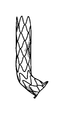
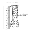
限定ではなく説明の目的で、ここで具現するように、また図1に示すように、プロテーゼは、デリバリシステムの遠領域上での経カテーテル大静脈肺動脈バイパスのために提供される。図示するように、装置は、起伏する「ジグザグ」パターンを有するリング状の部分から形成される管状並びにステント状の構造を有する。まず、プロテーゼの近端は、プロテーゼの最近傍のリングによって画定される起伏端を有する。遠端は、起伏状の材料のリングから形成される、同様の起伏する端を有するが、材料は熱処理され、プロテーゼの中央長手方向に略平行な第1の方向から「反転」されており、膨張が許容された場合に、プロテーゼの長手方向に略垂直な先端を有する折り曲げられたフランジへと変化する。フランジは、長手方向に対して任意の好適な角度で展開可能であり、好ましくは長手方向に対して垂直、あるいは、プロテーゼの壁に対してわずかな鋭角(70度から90度の間)を有してもよい。フランジは、血管あるいは他の組織壁の開口を介してプロテーゼの残りの部分を前進させる際に、血管あるいは他の組織壁の内側に対して引っ張る場合に有益であり、乗り越えてしまうことを防止し、グレン並びにフォンタン手術だけでなく容易化された吻合手術を主に可能にする。 For purposes of illustration, but not limitation, as embodied here and as shown in FIG. 1, the prosthesis is provided for transcatheter vena cava pulmonary artery bypass over a distant region of the delivery system. As shown, the device has a tubular and stent-like structure formed from ring-shaped portions with an undulating "zigzag" pattern. First, the near end of the prosthesis has an undulating end defined by the ring closest to the prosthesis. The far end has a similar undulating end formed from a ring of undulating material, but the material has been heat treated and "reversed" from a first direction approximately parallel to the central longitudinal direction of the prosthesis. If expansion is allowed, it changes to a bent flange with a tip that is approximately perpendicular to the longitudinal direction of the prosthesis. The flange can be deployed at any suitable angle with respect to the longitudinal direction, preferably perpendicular to the longitudinal direction or with a slight acute angle (between 70 and 90 degrees) with respect to the prosthesis wall. You may. Flange is beneficial when pulling against the inside of the vessel or other tissue wall as it advances the rest of the prosthesis through the opening of the vessel or other tissue wall and prevents it from getting over. It mainly enables simplified anastomotic surgery as well as Glenn and Fontan surgery.
図示するように、プロテーゼの近端は、起伏状リングの巻線を介して送られる、それを通るテザーを受ける。テザーは、コアを形成するコア部材、あるいはデリバリシステムのプッシュロッドを通る管状部材(例えば、さや)の近傍を介して引き出される。コアは、さやに対してスライド可能に配置可能である。プロテーゼをマウントした状態でコア部材をさやの遠側及び外側に前進させることで、プロテーゼは自己拡張する。しかしながら、さやに張力が加わっている場合、プロテーゼの近端が放射状に内側につぶれ、これによってプロテーゼがさやの内部へと引き出される。プロテーゼの、特に当該プロテーゼの遠端近傍の隣接する起伏状のリングは、互いに(例えば、縫合によって)接続可能であるが、互いに独立した状態で維持されて、内側及び/又は外側管状布層に取り付け可能でもある。所望の性能を得るために、プロテーゼの剛性が選択及び/または構成される。従って、遠端は、開状態で血管あるいは他の器官の壁内で開いた状態を維持するよう、比較的硬質であり、当該開状態は、プロテーゼが血管の壁からの穴を「閉じようと」する力に抗してプロテーゼが通った状態である。近領域は、剛性が低く、それがマウントされる血管の血管曲率を増大することができる。 As shown, the near end of the prosthesis receives a tether through which it is fed through the windings of the undulating ring. The tether is pulled out via the vicinity of a core member forming the core or a tubular member (eg, sheath) that passes through the push rods of the delivery system. The core can be slidably placed relative to the pod. The prosthesis self-expands by advancing the core member far and outward of the pod with the prosthesis mounted. However, when tension is applied to the pods, the near ends of the prosthesis squeeze inward radially, which pulls the prosthesis into the pods. Adjacent undulating rings of the prosthesis, especially near the far end of the prosthesis, are connectable to each other (eg, by sutures) but are maintained independent of each other into the medial and / or lateral tubular fabric layers. It can also be attached. The stiffness of the prosthesis is selected and / or configured to obtain the desired performance. Thus, the far end is relatively rigid to remain open within the walls of the vessel or other organ in the open state, in which the prosthesis attempts to "close" the hole from the wall of the vessel. The prosthesis has passed against the force of ". The near region is less rigid and can increase the vascular curvature of the vessel on which it is mounted.
デリバリシステムは、典型的には、ガイドワイヤが通過可能な非外傷性の遠端を有し、例えば、蛍光透視法におけるビジュアル化を容易にするための1つ以上の放射線不透過性マーカを備えてよい。(デリバリシステムに装填された場合にプロテーゼを囲む)デリバリシステムのさやの遠端あるいは端部領域もまた、放射線不透過性マーカを備えてよい。 The delivery system typically has a non-traumatic far end through which the guide wire can pass, eg, with one or more radiation opaque markers to facilitate visualization in fluoroscopy. It's okay. The far or end region of the pod of the delivery system (which surrounds the prosthesis when loaded into the delivery system) may also be provided with a radiation impermeable marker.
図2A−2Dは、図12を参照して後述して詳細に説明するクラムシェル状の装填ツールを用いたデリバリシステムのコア部材へのプロテーゼの装填を示す。図2Cは、つぶれた状態のデリバリシステムを示す。デリバリシステムは、それを通るガイドワイヤ内腔を画定する上記コア部材を備える。さやはコアに取り付けられ、テザーはコアとさやとの間の環状の空間内の構成要素間に渡って展開される。図3Aに示すように、さやが近傍に前進することで、プロテーゼのフレア状の遠端が、0から90度で反転する。プロテーゼの近端は、テザーの張力が解除されるまで、テザーによって放射状にかつ内側に保持される。テザーが取り外されない限り、プロテーゼが完全に取り外し可能であるようにするため、テザーに張力を再度加えることも可能である。 2A-2D shows the loading of the prosthesis into the core member of the delivery system using a clamshell loading tool, which will be described in detail below with reference to FIG. FIG. 2C shows a delivery system in a collapsed state. The delivery system comprises the core member defining a guidewire lumen through which it passes. The pods are attached to the core and the tethers are deployed across the components within the annular space between the cores and pods. As shown in FIG. 3A, the flared far end of the prosthesis is inverted at 0 to 90 degrees as the pod advances closer. The near end of the prosthesis is held radially and inward by the tether until the tether is re-tensioned. It is also possible to re-tension the tether to ensure that the prosthesis is completely removable unless the tether is removed.
図4Aは、グレン手術のための本開示のプロテーゼを示す。プロテーゼの遠領域は、柔軟性を有し、プロテーゼが曲がった血管を通過できるようにする。図4Dは、グレン手術において、プロテーゼの近端が上大静脈へ延伸した状態で、主肺動脈(MPA)の内壁に対して引っ張られるプロテーゼのフランジ遠端を示す。 FIG. 4A shows the prosthesis of the present disclosure for Glenn surgery. The far area of the prosthesis is flexible and allows the prosthesis to pass through curved blood vessels. FIG. 4D shows the far end of the flange of the prosthesis pulled against the inner wall of the main pulmonary artery (MPA) in Glenn surgery with the near end of the prosthesis extending into the superior vena cava.
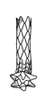
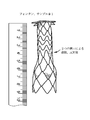
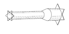
図5Aは、フォンタン型プロテーゼの概要斜視図であり、図5Bは、当該プロテーゼの側面概要図である。プロテーゼのフレームワークの隣接リングは、好ましくはフレームワークのリングを通過する管状の布に(例えば縫合によって)取り付けられ、フレームワークは、例えば、.014インチの直径のNiTiから形成される。各構造リングの長手方向寸法は、異なっていてよい。例えば、プロテーゼの領域「A」は、比較的剛性が高く、リングは直接あるいは布を介して互いに取り付け可能で、領域B、C、D、及びEは、それとは異なり、剛性が低い。 FIG. 5A is a schematic perspective view of the Fontan type prosthesis, and FIG. 5B is a side schematic view of the prosthesis. The adjacent ring of the framework of the prosthesis is preferably attached to a tubular cloth (eg by suture) that passes through the ring of the framework, and the framework is described, for example. Formed from NiTi with a diameter of 014 inches. The longitudinal dimensions of each structural ring may be different. For example, the area "A" of the prosthesis is relatively rigid, the rings can be attached to each other either directly or via cloth, and areas B, C, D, and E are different and less rigid.
図6Aは、フォンタン手術のためのプロテーゼについての第1の実施の形態を示す。ボディは、図5のプロテーゼのものと同様であるが、例えば.013インチのNiTiワイヤから形成される。図6Bは、同じワイヤから形成される第2の実施の形態を示すが、フランジが鋭角で形成され、プロテーゼが展開される際に遠端フランジの反転あるいは移動量を増加させる。プロテーゼは、中央領域において布に1つ以上の(例えば、2つの)窓部を備えてよく、プロテーゼが、主肺動脈内に展開されたその遠端から上大静脈へ広がる際に漏出物を右心房に入れるようにする。以下の表は、図5Bに示すプロテーゼについて好適な寸法例を示す。 FIG. 6A shows a first embodiment of a prosthesis for the Fontan procedure. The body is similar to that of the prosthesis of FIG. 5, but for example. Formed from 013 inch NiTi wire. FIG. 6B shows a second embodiment formed from the same wire, where the flanges are formed at an acute angle to increase the amount of reversal or movement of the far end flange as the prosthesis is deployed. The prosthesis may have one or more (eg, two) windows on the fabric in the central region, and the prosthesis is to the right of the leak as it spreads from its far end into the superior vena cava into the main pulmonary artery. Try to put it in the atrium. The table below shows suitable dimensional examples for the prosthesis shown in FIG. 5B.

各プロテーゼの端における星形のフランジは、血管内でプロテーゼを固定させるのに有用である。いくつかの実施の形態においては、テザーは、デリバリシステムの長手方向に沿って平行な内腔を伝って展開可能で、互いに絡まってしまうことを防止する。フォンタン手術のプロテーゼは、好ましくは、図6Bに示すようにフレア状近領域を備え、壁の並置を強化する。 A star-shaped flange at the end of each prosthesis is useful for anchoring the prosthesis within the blood vessel. In some embodiments, the tether can be deployed along a parallel lumen along the longitudinal direction of the delivery system to prevent it from becoming entangled with each other. The Fontan procedure prosthesis preferably comprises a flared near region as shown in FIG. 6B to enhance wall juxtaposition.
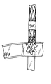
図7は、本開示のデリバリシステムを用いる、開示のプロテーゼの2つが取り付けられた動物モデルを示し、一方は(上大静脈(SVC)から主肺動脈(MPA)に血液を供給するためにSVCをMPAに接続する)グレン手術におけるもので、他方は(心室を介して下大静脈(IVC)を主肺動脈(MPA)に接続する)フォンタン手術におけるものであり、プロテーゼは、心室内へ漏出物を入れるようにする窓部を備える。 FIG. 7 shows an animal model fitted with two of the disclosed prostheses using the delivery system of the present disclosure, one of which uses the SVC to supply blood from the superior aorta (SVC) to the main pulmonary artery (MPA). In Glenn surgery (connecting to MPA), the other in Fontan surgery (connecting the inferior aorta (IVC) to the main pulmonary artery (MPA) through the ventricles), the prosthesis leaks into the ventricles. It is equipped with a window to allow it to enter.
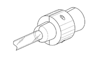
図8Aは、プロテーゼ(グレンあるいはフォンタン手術用)がマウントされたデリバリシステムを示す。図8Bは、コアと、前進した遠端とを示し、プロテーゼのフレア状の遠端が展開されている。図8Cは、プロテーゼのフレア状遠端のクローズアップ図である。図8Dは、プロテーゼの大部分が展開されているが、テザーに張力が加わってプロテーゼの近端が放射状に内側に保持されている状態を示す。図9A及び9Bは、上述したプロテーゼについての2つの異なる実施の形態を示し、図9Cは、プロテーゼがデリバリシステムのさや内でつぶれた状態を示し、図9Dは、各プロテーゼのデリバリシステムの近端を示す。図9Eは、用途に応じて適用可能な異なるサイズの遠端を示す。遠端は、装置の中央のガイドワイヤ内腔に対して遠側かつ外側に延伸するガイドワイヤに対する応力緩衝部として機能する。そのため、端部は比較的長いことが望ましいが、デリバリシステムが斜めに進入する際に、比較的狭い内腔を案内しないように、長すぎないことも有用である。 FIG. 8A shows a delivery system with a prosthesis (for Glen or Fontan procedure) mounted. FIG. 8B shows the core and the forward far end, with the flared far end of the prosthesis unfolded. FIG. 8C is a close-up view of the flared far end of the prosthesis. FIG. 8D shows a state in which most of the prosthesis is unfolded, but tension is applied to the tether to hold the near end of the prosthesis radially inward. 9A and 9B show two different embodiments for the prostheses described above, FIG. 9C shows the prosthesis collapsed within the pods of the delivery system, and FIG. 9D shows the near end of the delivery system for each prosthesis. Is shown. FIG. 9E shows far ends of different sizes applicable depending on the application. The far end acts as a stress buffer for the guidewire extending distant and outward with respect to the central guidewire lumen of the device. Therefore, it is desirable that the ends be relatively long, but it is also useful that they are not too long so that they do not guide the relatively narrow lumen when the delivery system enters at an angle.
図10A−10Bは、フランジ端を有するプロテーゼの側面図及び等角図法による図である。図10C−10Dは、(プロテーゼ展開時の)フランジ状の近端とともにフランジ状の遠端を有するプロテーゼの側面図及び等角図法による図である。図示するプロテーゼは、比較的大きな径を有する例えばフランジ端近傍の第1の部分であって、小さな径を有する領域に移行する移行部である第1の部分を有する。プロテーゼは、また、調整可能な伸縮長さを有してよい。内径は、好ましくは、プロテーゼの長さが調整された場合に略不変である。 10A-10B are side views and isometric views of the prosthesis having flange ends. 10C-10D are side views and isometric views of a prosthesis having a flange-like near end as well as a flange-like far end (when the prosthesis is deployed). The illustrated prosthesis has a first portion having a relatively large diameter, eg, near the flange end, which is a transition portion that transitions to a region having a small diameter. The prosthesis may also have an adjustable stretch length. The inner diameter is preferably substantially invariant when the length of the prosthesis is adjusted.
図11A−11Bは、管状の構造領域に取り付けられた2つのフランジ端を有する調整可能な長さのプロテーゼを示し、それらはばね等の弾性部材によって中央領域において連結されている。管状の布部材は、好ましくは、プロテーゼの長さ方向に沿って内側あるいは外側を通過する。図示するプロテーゼは、図の理解の容易化する目的で管状の布部材を有していないが、各端は、互いに異なる直径を有してよい。このようなプロテーゼは、例えば大動脈を減圧するために下行大動脈から主肺動脈までのシャントを形成するのに有用である。プロテーゼの長さは調整可能で、ばねによってプロテーゼに張力が維持され、これがフランジ端を大動脈及びMPAの内壁に対して安定する際の一助となる。 11A-11B show adjustable length prostheses with two flange ends attached to a tubular structural region, which are connected in the central region by elastic members such as springs. The tubular fabric member preferably passes inside or outside along the length direction of the prosthesis. The illustrated prosthesis does not have a tubular fabric member for the purpose of facilitating the comprehension of the figure, but each end may have different diameters from each other. Such prostheses are useful, for example, to form a shunt from the descending aorta to the main pulmonary artery to decompress the aorta. The length of the prosthesis is adjustable and the springs maintain tension in the prosthesis, which helps stabilize the flange ends against the aorta and the inner wall of the MPA.
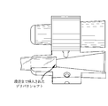
図12A−12Hは、本開示に係るプロテーゼ装填ツールの態様を示す。図示するように、装填ツールは、2つの部分を有し、その内面を図12A及び12Bに示す。内部チャンネルは、比較的大きな径から比較的小さな径に絞られる第1のファンネル部であって、一定の径を有する第2の領域に移行する第1のファンネル部を有するが、小さな径の領域に段差あるいは肩を有し、これによってファンネル部が効果的に一定の径を有する領域よりも若干小さな径を有している。図12C−12Eに示すように、2つの部分は、ツールの一方の一組の突起が、ツールの他方の一組の切り欠きあるいは穴に挿入されることで互いに位置合わせされて合体される。使用においては、プロテーゼを覆うさやの遠端が、一定の径の部分を有するプロテーゼの一端に、肩に当接するまで挿入される。使用において、デリバリシステムの中央シャフトがさや及びファンネル部分を通過する。テザーがその近端に取り付けられたプロテーゼは、その後、ファンネルに向かって押し込まれ、さやの内側にフィットするように、そしてデリバリシステムの中央シャフトあるいは管状コア部材を包囲する。ファンネル部に向かってプロテーゼを押し込むことで、圧縮力が働くようになる。プロテーゼを装填した後は、装填ツールは単に取り外される。 12A-12H show aspects of the prosthesis loading tool according to the present disclosure. As shown, the loading tool has two parts, the inner surfaces of which are shown in FIGS. 12A and 12B. The internal channel is a first funnel portion narrowed down from a relatively large diameter to a relatively small diameter, having a first funnel portion transitioning to a second region having a constant diameter, but a small diameter region. Has a step or shoulder, which allows the funnel portion to have a diameter slightly smaller than the region effectively having a constant diameter. As shown in FIGS. 12C-12E, the two parts are aligned and united with each other by inserting one set of protrusions on the tool into the other set of notches or holes in the tool. In use, the far end of the sheath covering the prosthesis is inserted into one end of the prosthesis with a portion of constant diameter until it touches the shoulder. In use, the central shaft of the delivery system passes through the pods and funnel sections. The prosthesis with the tether attached to its near end is then pushed towards the funnel to fit inside the pod and surround the central shaft or tubular core member of the delivery system. By pushing the prosthesis toward the funnel, compressive force works. After loading the prosthesis, the loading tool is simply removed.
一般に、展開中に、デリバリシステムは、プロテーゼを展開すべき位置まで前進させられる。次に、ガイドワイヤの遠端及びコアを、プロテーゼと同様に遠側へ前進させ、プロテーゼのフランジを、血管あるいは他の組織の壁の開口を介して展開する。次に、フランジ端を、血管の内壁に押し付ける。デリバリシステムの近端において対応するマーカを用いてよく、これによってフランジがどのポイントまで前進して展開されたか確認できる。次に、デリバリシステムを近側に若干引っ張り、フランジを固定させる。固定が十分な場合、ユーザは、デリバリシステムの内側シャフトを保持し、外側さやを後退させて全インプラントを解放する。その後、テザーが張力から解放されてインプラントの近端が開く。最後に、ユーザはテザーの一端を引っ張りインプラントを取り外し、デリバリシステムを取り外すことができる。しかしながら、必要であれば、テザーの取り外しの前に、テザーに再度張力を加えてよく、これによってプロテーゼの近端が放射状に内側につぶれ、プロテーゼがデリバリシステムのさやに退避されて取り外される。 Generally, during deployment, the delivery system is advanced to the position where the prosthesis should be deployed. The far end and core of the guide wire are then advanced as far away as the prosthesis, and the flange of the prosthesis is unfolded through an opening in the wall of a blood vessel or other tissue. The flange end is then pressed against the inner wall of the blood vessel. Corresponding markers may be used at the near end of the delivery system, which allows you to see to what point the flange has advanced and deployed. Next, the delivery system is pulled slightly closer to fix the flange. If the fixation is sufficient, the user holds the inner shaft of the delivery system and retracts the outer pod to release the entire implant. The tether is then released from tension and the near end of the implant opens. Finally, the user can remove the implant by pulling on one end of the tether and remove the delivery system. However, if necessary, the tether may be re-tensioned prior to removal of the tether, which causes the near end of the prosthesis to radiate inward and retract the prosthesis into the pod of the delivery system for removal.
本明細書に開示した装置及び方法は、そのまま、あるいは特定の方法に好適なように変形したうえで、他の方法に適用できる。本発明の原理を適用可能な多数の可能性のある実施の形態を鑑みて、例示した実施の形態はあくまでも本開示の好適な実施の形態であり、本開示の技術的範囲を限定するものと認識されるべきではない。 The devices and methods disclosed herein can be applied to other methods as they are or after being modified to suit a particular method. In view of the many possible embodiments to which the principles of the present invention can be applied, the illustrated embodiments are merely preferred embodiments of the present disclosure and limit the technical scope of the present disclosure. Should not be recognized.
Claims (15)
第1の血管の壁に対する前記プロテーゼの固定の一助となる遠フランジと、
遠領域であって、前記遠領域が通る前記第1の血管の壁に形成される穴の開状態を維持するのに十分な剛性を有し、前記遠フランジの近傍から延伸する遠領域と、
前記遠領域の近傍から延伸する伸展性中間領域であって、前記遠領域よりも伸展性を有し、内側の管状の布及び外側の管状の布の少なくとも1つに取り付けられた複数の起伏状のストラットリングを含み、組み合わせ構造が柔軟性及び伸展性を提供して折り曲げられた際に完全な開通性を許容し、最大で90度まで折り曲げられるようにさらに構成された伸展性中間領域と、
互いに接続された複数の隣接する起伏状のストラットリングを有し、第2の血管の壁に対して固定され、押し付けられるのに十分な剛性を有する近領域と、
テザーを含む起伏状の近端であって、前記テザーは開口に通され、前記テザーに張力が加えられた場合に放射状に内側につぶれる前記プロテーゼの近端と、
を備え、
前記プロテーゼの側壁を介した少なくとも1つの窓部を画定し、体液の漏出を前記窓部を介して許容する、
ことを特徴とするプロテーゼ。 An enhanced end-graft shunt prosthesis,
A far flange that helps secure the prosthesis to the wall of the first vessel,
A distant region that is rigid enough to maintain an open state of a hole formed in the wall of the first blood vessel through which the distant region passes and extends from the vicinity of the distant flange.
A plurality of undulating shapes extending from the vicinity of the far region, which are more extensible than the far region and are attached to at least one of the inner tubular cloth and the outer tubular cloth. With an extensible intermediate region, including a strut ring, the combined structure provides flexibility and extensibility, allows full openness when folded, and is further configured to fold up to 90 degrees.
A near region that has multiple adjacent undulating struts connected to each other and is rigid enough to be secured and pressed against the wall of the second vessel.
An undulating near end containing a tether, the tether being passed through an opening and radially inwardly collapsing when tension is applied to the tether and the near end of the prosthesis.
Equipped with a,
At least one window is defined through the side wall of the prosthesis, allowing fluid to leak through the window.
A prosthesis characterized by that.
前記遠フランジは、マルチポイントのスターの形状である、
ことを特徴とする請求項1に記載のプロテーゼ。 When not pressed, it is configured and arranged to radiate outwardly self-expand.
The far flange is in the shape of a multipoint star.
The prosthesis according to claim 1.
各フランジ端は、前記プロテーゼが第1のボディ内腔と第2のボディ内腔との壁に設けられた開口を介してマウントされる際に、前記第1のボディ内腔及び前記第2のボディ内腔に押しつけられるよう構成される、ことを特徴とする請求項1に記載のプロテーゼ。 The prosthesis further comprises a flange at the near end of the prosthesis.
Each flange end is the first body cavity and the second body as the prosthesis is mounted through an opening provided in the wall between the first body cavity and the second body cavity. The prosthesis according to claim 1, wherein the prosthesis is configured to be pressed against the lumen of the body.
前記プロテーゼは、長手方向内側部材と、退避可能なさやの内側とにマウントされることを特徴とするデリバリシステム。 A delivery system in which the prosthesis according to claim 1 is mounted.
The prosthesis delivery system characterized by being mounted in the longitudinal inner member, and an inner retractable sheath.
Applications Claiming Priority (5)
| Application Number | Priority Date | Filing Date | Title |
|---|---|---|---|
| US201562219118P | 2015-09-15 | 2015-09-15 | |
| US62/219,118 | 2015-09-15 | ||
| US201662363716P | 2016-07-18 | 2016-07-18 | |
| US62/363,716 | 2016-07-18 | ||
| PCT/US2016/052005 WO2017049003A1 (en) | 2015-09-15 | 2016-09-15 | Devices and methods for effectuating percutaneous glenn and fontan procedures |
Publications (3)
| Publication Number | Publication Date |
|---|---|
| JP2018528009A JP2018528009A (en) | 2018-09-27 |
| JP2018528009A5 JP2018528009A5 (en) | 2018-11-08 |
| JP6869967B2 true JP6869967B2 (en) | 2021-05-12 |
Family
ID=58257893
Family Applications (1)
| Application Number | Title | Priority Date | Filing Date |
|---|---|---|---|
| JP2018514884A Active JP6869967B2 (en) | 2015-09-15 | 2016-09-15 | Equipment and methods for performing percutaneous Glen and Fontan procedures |
Country Status (4)
| Country | Link |
|---|---|
| US (3) | US10426482B2 (en) |
| EP (1) | EP3349687B1 (en) |
| JP (1) | JP6869967B2 (en) |
| WO (1) | WO2017049003A1 (en) |
Families Citing this family (6)
| Publication number | Priority date | Publication date | Assignee | Title |
|---|---|---|---|---|
| JP6869967B2 (en) | 2015-09-15 | 2021-05-12 | ザ ユナイテッド ステイツ オブ アメリカ, アズ リプレゼンテッド バイ ザ セクレタリー, デパートメント オブ ヘルス アンド ヒューマン サービスThe United States Of America, As Represented By The Secretary, Department Of Health And Human Service | Equipment and methods for performing percutaneous Glen and Fontan procedures |
| EP3691568A4 (en) * | 2017-09-01 | 2021-08-25 | Transmural Systems LLC | Percutaneous shunt devices and related methods |
| US11717429B2 (en) * | 2018-09-19 | 2023-08-08 | Nxt Biomedical, Llc | Methods and technology for creating connections and shunts between vessels and chambers of biologic structures |
| US20200101270A1 (en) * | 2018-09-24 | 2020-04-02 | Michael Warren Sutherland | Pulmonary arterial compliance enhancement and control device |
| JP2022519869A (en) | 2019-02-07 | 2022-03-25 | エヌエックスティー バイオメディカル,エルエルシー | Rivet shunt and placement method |
| EP4009903A1 (en) * | 2019-08-06 | 2022-06-15 | Edwards Lifesciences Corporation | External cardiac bypass shunting |
Family Cites Families (155)
| Publication number | Priority date | Publication date | Assignee | Title |
|---|---|---|---|---|
| CA1069652A (en) | 1976-01-09 | 1980-01-15 | Alain F. Carpentier | Supported bioprosthetic heart valve with compliant orifice ring |
| AR221872A1 (en) | 1979-03-16 | 1981-03-31 | Liotta Domingo S | IMPROVEMENTS IN IMPANTABLE HEART VALVES |
| IT1208326B (en) | 1984-03-16 | 1989-06-12 | Sorin Biomedica Spa | CARDIAC VALVE PROSTHESIS PROVIDED WITH VALVES OF ORGANIC FABRIC |
| CH672247A5 (en) | 1986-03-06 | 1989-11-15 | Mo Vysshee Tekhnicheskoe Uchil | |
| US5411552A (en) | 1990-05-18 | 1995-05-02 | Andersen; Henning R. | Valve prothesis for implantation in the body and a catheter for implanting such valve prothesis |
| BR9205978A (en) | 1991-05-08 | 1994-07-26 | Nika Health Products Ltd | Process and apparatus for the production of a heart valve prosthesis |
| US5449384A (en) | 1992-09-28 | 1995-09-12 | Medtronic, Inc. | Dynamic annulus heart valve employing preserved porcine valve leaflets |
| US5639278A (en) * | 1993-10-21 | 1997-06-17 | Corvita Corporation | Expandable supportive bifurcated endoluminal grafts |
| ES2187554T3 (en) | 1995-02-07 | 2003-06-16 | Bard Inc C R | BINDER OF ELASTIC BANDS IN TELESCOPIC TYPE SERIES. |
| WO1996036297A1 (en) * | 1995-05-19 | 1996-11-21 | Kanji Inoue | Transplantation instrument, method of bending same and method of transplanting same |
| ES2293653T3 (en) * | 1995-12-14 | 2008-03-16 | Gore Enterprise Holdings, Inc. | REINFORCEMENT OF STENT RESISTANT TO RETORCIMIENTO. |
| US5861028A (en) | 1996-09-09 | 1999-01-19 | Shelhigh Inc | Natural tissue heart valve and stent prosthesis and method for making the same |
| US5749921A (en) * | 1996-02-20 | 1998-05-12 | Medtronic, Inc. | Apparatus and methods for compression of endoluminal prostheses |
| US6090136A (en) * | 1996-07-29 | 2000-07-18 | Radiance Medical Systems, Inc. | Self expandable tubular support |
| EP0850607A1 (en) | 1996-12-31 | 1998-07-01 | Cordis Corporation | Valve prosthesis for implantation in body channels |
| US5928281A (en) | 1997-03-27 | 1999-07-27 | Baxter International Inc. | Tissue heart valves |
| US5895410A (en) | 1997-09-12 | 1999-04-20 | B. Braun Medical, Inc. | Introducer for an expandable vascular occlusion device |
| US7491232B2 (en) | 1998-09-18 | 2009-02-17 | Aptus Endosystems, Inc. | Catheter-based fastener implantation apparatus and methods with implantation force resolution |
| US6106510A (en) | 1998-05-28 | 2000-08-22 | Medtronic, Inc. | Extruded guide catheter shaft with bump extrusion soft distal segment |
| WO2000015147A1 (en) | 1998-09-10 | 2000-03-23 | Percardia, Inc. | Transmycardial shunt and its attachment mechanism, for left ventricular revascularization |
| JP2002526193A (en) | 1998-09-18 | 2002-08-20 | ユナイテッド ステイツ サージカル コーポレーション | Intravascular fastener applicator |
| US6059769A (en) | 1998-10-02 | 2000-05-09 | Medtronic, Inc. | Medical catheter with grooved soft distal segment |
| US6152937A (en) | 1998-11-06 | 2000-11-28 | St. Jude Medical Cardiovascular Group, Inc. | Medical graft connector and methods of making and installing same |
| US6059824A (en) * | 1998-12-23 | 2000-05-09 | Taheri; Syde A. | Mated main and collateral stent and method for treatment of arterial disease |
| US6736845B2 (en) | 1999-01-26 | 2004-05-18 | Edwards Lifesciences Corporation | Holder for flexible heart valve |
| US6364905B1 (en) | 1999-01-27 | 2002-04-02 | Sulzer Carbomedics Inc. | Tri-composite, full root, stentless valve |
| US6248122B1 (en) * | 1999-02-26 | 2001-06-19 | Vascular Architects, Inc. | Catheter with controlled release endoluminal prosthesis |
| AU772615B2 (en) * | 1999-05-03 | 2004-05-06 | Ventrica, Inc. | Methods and devices for placing a conduit in fluid communication with a target vessel |
| US6790229B1 (en) | 1999-05-25 | 2004-09-14 | Eric Berreklouw | Fixing device, in particular for fixing to vascular wall tissue |
| US6346116B1 (en) | 1999-08-03 | 2002-02-12 | Medtronic Ave, Inc. | Distal protection device |
| SE515231C2 (en) * | 1999-10-13 | 2001-07-02 | Jan Otto Solem | Covered stent and way to manufacture the same |
| US20070043435A1 (en) | 1999-11-17 | 2007-02-22 | Jacques Seguin | Non-cylindrical prosthetic valve system for transluminal delivery |
| US7195641B2 (en) | 1999-11-19 | 2007-03-27 | Advanced Bio Prosthetic Surfaces, Ltd. | Valvular prostheses having metal or pseudometallic construction and methods of manufacture |
| US6458153B1 (en) | 1999-12-31 | 2002-10-01 | Abps Venture One, Ltd. | Endoluminal cardiac and venous valve prostheses and methods of manufacture and delivery thereof |
| US6953476B1 (en) | 2000-03-27 | 2005-10-11 | Neovasc Medical Ltd. | Device and method for treating ischemic heart disease |
| IL153753A0 (en) | 2002-12-30 | 2003-07-06 | Neovasc Medical Ltd | Varying-diameter vascular implant and balloon |
| US6454799B1 (en) | 2000-04-06 | 2002-09-24 | Edwards Lifesciences Corporation | Minimally-invasive heart valves and methods of use |
| US6602271B2 (en) | 2000-05-24 | 2003-08-05 | Medtronic Ave, Inc. | Collapsible blood filter with optimal braid geometry |
| US7510572B2 (en) | 2000-09-12 | 2009-03-31 | Shlomo Gabbay | Implantation system for delivery of a heart valve prosthesis |
| US7374571B2 (en) | 2001-03-23 | 2008-05-20 | Edwards Lifesciences Corporation | Rolled minimally-invasive heart valves and methods of manufacture |
| US6733525B2 (en) | 2001-03-23 | 2004-05-11 | Edwards Lifesciences Corporation | Rolled minimally-invasive heart valves and methods of use |
| US6911036B2 (en) | 2001-04-03 | 2005-06-28 | Medtronic Vascular, Inc. | Guidewire apparatus for temporary distal embolic protection |
| US6818006B2 (en) | 2001-04-03 | 2004-11-16 | Medtronic Vascular, Inc. | Temporary intraluminal filter guidewire |
| US6866677B2 (en) | 2001-04-03 | 2005-03-15 | Medtronic Ave, Inc. | Temporary intraluminal filter guidewire and methods of use |
| US7044958B2 (en) | 2001-04-03 | 2006-05-16 | Medtronic Vascular, Inc. | Temporary device for capturing embolic material |
| FR2826863B1 (en) | 2001-07-04 | 2003-09-26 | Jacques Seguin | ASSEMBLY FOR PLACING A PROSTHETIC VALVE IN A BODY CONDUIT |
| US20030065386A1 (en) | 2001-09-28 | 2003-04-03 | Weadock Kevin Shaun | Radially expandable endoprosthesis device with two-stage deployment |
| CA2462509A1 (en) | 2001-10-04 | 2003-04-10 | Neovasc Medical Ltd. | Flow reducing implant |
| US20050177180A1 (en) | 2001-11-28 | 2005-08-11 | Aptus Endosystems, Inc. | Devices, systems, and methods for supporting tissue and/or structures within a hollow body organ |
| US20050070992A1 (en) | 2001-11-28 | 2005-03-31 | Aptus Endosystems, Inc. | Prosthesis systems and methods sized and configured for the receipt and retention of fasteners |
| EP1448117B1 (en) | 2001-11-28 | 2013-05-22 | Aptus Endosystems, Inc. | Endovascular aneurysm repair system |
| US7147657B2 (en) | 2003-10-23 | 2006-12-12 | Aptus Endosystems, Inc. | Prosthesis delivery systems and methods |
| US7137993B2 (en) * | 2001-12-03 | 2006-11-21 | Xtent, Inc. | Apparatus and methods for delivery of multiple distributed stents |
| US7105021B2 (en) * | 2002-04-25 | 2006-09-12 | Scimed Life Systems, Inc. | Implantable textile prostheses having PTFE cold drawn yarns |
| EP1534180A4 (en) | 2002-08-08 | 2007-04-04 | Neovasc Medical Ltd | Geometric flow regulator |
| WO2004014474A1 (en) | 2002-08-08 | 2004-02-19 | Neovasc Medical Ltd. | Flow reducing implant |
| US8075585B2 (en) | 2002-08-29 | 2011-12-13 | Stryker Corporation | Device and method for treatment of a vascular defect |
| US8518096B2 (en) * | 2002-09-03 | 2013-08-27 | Lifeshield Sciences Llc | Elephant trunk thoracic endograft and delivery system |
| US7404824B1 (en) | 2002-11-15 | 2008-07-29 | Advanced Cardiovascular Systems, Inc. | Valve aptation assist device |
| US7189259B2 (en) | 2002-11-26 | 2007-03-13 | Clemson University | Tissue material and process for bioprosthesis |
| US7399315B2 (en) | 2003-03-18 | 2008-07-15 | Edwards Lifescience Corporation | Minimally-invasive heart valve with cusp positioners |
| US7294135B2 (en) | 2003-03-20 | 2007-11-13 | Medtronic Vascular, Inc | Control handle for intraluminal devices |
| WO2004087236A2 (en) | 2003-03-28 | 2004-10-14 | Board Of Regents, The University Of Texas System | Stents and methods for creating an anastomosis |
| JP2004298472A (en) * | 2003-03-31 | 2004-10-28 | Clinical Supply:Kk | Stent |
| US7998188B2 (en) | 2003-04-28 | 2011-08-16 | Kips Bay Medical, Inc. | Compliant blood vessel graft |
| US7316706B2 (en) | 2003-06-20 | 2008-01-08 | Medtronic Vascular, Inc. | Tensioning device, system, and method for treating mitral valve regurgitation |
| US7201772B2 (en) | 2003-07-08 | 2007-04-10 | Ventor Technologies, Ltd. | Fluid flow prosthetic device |
| US7160322B2 (en) | 2003-08-13 | 2007-01-09 | Shlomo Gabbay | Implantable cardiac prosthesis for mitigating prolapse of a heart valve |
| WO2005037133A2 (en) | 2003-10-10 | 2005-04-28 | Arshad Quadri | System and method for endoluminal grafting of bifurcated and branched vessels |
| WO2005046488A2 (en) | 2003-11-12 | 2005-05-26 | Medtronic Vascular, Inc. | Cardiac valve annulus reduction system |
| US7955384B2 (en) | 2003-11-12 | 2011-06-07 | Medtronic Vascular, Inc. | Coronary sinus approach for repair of mitral valve regurgitation |
| US7716801B2 (en) | 2003-11-24 | 2010-05-18 | Medtronic Vascular, Inc. | Low-profile distal protection device |
| JP2005178627A (en) | 2003-12-19 | 2005-07-07 | Toyota Motor Corp | Integrated control system for vehicle |
| US7445631B2 (en) | 2003-12-23 | 2008-11-04 | Sadra Medical, Inc. | Methods and apparatus for endovascularly replacing a patient's heart valve |
| US7959666B2 (en) | 2003-12-23 | 2011-06-14 | Sadra Medical, Inc. | Methods and apparatus for endovascularly replacing a heart valve |
| JP4403183B2 (en) | 2004-02-05 | 2010-01-20 | チルドレンズ・メディカル・センター・コーポレイション | Transcatheter delivery of replacement heart valves |
| US9039724B2 (en) | 2004-03-19 | 2015-05-26 | Aga Medical Corporation | Device for occluding vascular defects |
| US8012201B2 (en) | 2004-05-05 | 2011-09-06 | Direct Flow Medical, Inc. | Translumenally implantable heart valve with multiple chamber formed in place support |
| US7842069B2 (en) | 2004-05-07 | 2010-11-30 | Nmt Medical, Inc. | Inflatable occluder |
| US9706997B2 (en) * | 2004-08-27 | 2017-07-18 | Rox Medical, Inc. | Device and method for establishing an artificial arterio-venous fistula |
| US7780721B2 (en) * | 2004-09-01 | 2010-08-24 | C. R. Bard, Inc. | Stent and method for manufacturing the stent |
| FR2874813B1 (en) | 2004-09-07 | 2007-06-22 | Perouse Soc Par Actions Simpli | VALVULAR PROSTHESIS |
| US7682352B2 (en) | 2004-09-28 | 2010-03-23 | Medtronic Vascular, Inc. | Catheter with curved distal section having reinforcing strip and method of making same |
| US20060085012A1 (en) | 2004-09-28 | 2006-04-20 | Medtronic Vascular, Inc. | Torquing device delivered over a guidewire to rotate a medical fastener |
| US20100106171A1 (en) * | 2005-05-06 | 2010-04-29 | Johns Hopkins University | Transcaval mesenteric venous anastomosis and access system |
| US7914569B2 (en) | 2005-05-13 | 2011-03-29 | Medtronics Corevalve Llc | Heart valve prosthesis and methods of manufacture and use |
| US20070067029A1 (en) | 2005-09-16 | 2007-03-22 | Shlomo Gabbay | Support apparatus to facilitate implantation of cardiac prosthesis |
| DE102005052628B4 (en) | 2005-11-04 | 2014-06-05 | Jenavalve Technology Inc. | Self-expanding, flexible wire mesh with integrated valvular prosthesis for the transvascular heart valve replacement and a system with such a device and a delivery catheter |
| AU2006315812B2 (en) | 2005-11-10 | 2013-03-28 | Cardiaq Valve Technologies, Inc. | Balloon-expandable, self-expanding, vascular prosthesis connecting stent |
| EP1991168B1 (en) | 2006-02-16 | 2016-01-27 | Transcatheter Technologies GmbH | Minimally invasive heart valve replacement |
| WO2007106755A1 (en) | 2006-03-10 | 2007-09-20 | Arbor Surgical Technologies, Inc. | Valve introducers and methods for making and using them |
| US7699892B2 (en) | 2006-04-12 | 2010-04-20 | Medtronic Vascular, Inc. | Minimally invasive procedure for implanting an annuloplasty device |
| DK2010102T3 (en) | 2006-04-12 | 2019-09-16 | Medtronic Vascular Inc | ANNULOPLASTIAN DEVICE WITH A SPIRAL ANCHOR |
| US7442207B2 (en) | 2006-04-21 | 2008-10-28 | Medtronic Vascular, Inc. | Device, system, and method for treating cardiac valve regurgitation |
| WO2007130881A2 (en) | 2006-04-29 | 2007-11-15 | Arbor Surgical Technologies, Inc. | Multiple component prosthetic heart valve assemblies and apparatus and methods for delivering them |
| US20070293942A1 (en) | 2006-06-16 | 2007-12-20 | Daryush Mirzaee | Prosthetic valve and deployment method |
| WO2008013915A2 (en) | 2006-07-28 | 2008-01-31 | Arshad Quadri | Percutaneous valve prosthesis and system and method for implanting same |
| US8876894B2 (en) | 2006-09-19 | 2014-11-04 | Medtronic Ventor Technologies Ltd. | Leaflet-sensitive valve fixation member |
| US8388680B2 (en) | 2006-10-18 | 2013-03-05 | Guided Delivery Systems, Inc. | Methods and devices for catheter advancement and delivery of substances therethrough |
| WO2008055301A1 (en) * | 2006-11-07 | 2008-05-15 | Univ Sydney | Devices and methods for the treatment of heart failure |
| ES2708789T3 (en) | 2006-12-19 | 2019-04-11 | St Jude Medical | Method for manufacturing a prosthetic heart valve that includes a structure of endoprostheses and tissue leaflets |
| US7753949B2 (en) | 2007-02-23 | 2010-07-13 | The Trustees Of The University Of Pennsylvania | Valve prosthesis systems and methods |
| US8070802B2 (en) | 2007-02-23 | 2011-12-06 | The Trustees Of The University Of Pennsylvania | Mitral valve system |
| CA2679614C (en) * | 2007-03-06 | 2014-11-18 | William A. Cook Australia Pty. Ltd | Endovascular deployment device |
| US7806917B2 (en) | 2007-04-17 | 2010-10-05 | Medtronic Vascular, Inc. | Stent graft fixation system and method |
| WO2009045334A1 (en) | 2007-09-28 | 2009-04-09 | St. Jude Medical, Inc. | Collapsible/expandable prosthetic heart valves with native calcified leaflet retention features |
| US8992593B2 (en) | 2007-12-26 | 2015-03-31 | Cook Medical Technologies Llc | Apparatus and methods for deployment of a modular stent-graft system |
| US7806919B2 (en) | 2008-04-01 | 2010-10-05 | Medtronic Vascular, Inc. | Double-walled stent system |
| JP5685183B2 (en) | 2008-04-23 | 2015-03-18 | メドトロニック,インコーポレイテッド | Heart valve device with stent |
| US7972370B2 (en) | 2008-04-24 | 2011-07-05 | Medtronic Vascular, Inc. | Stent graft system and method of use |
| US20090270976A1 (en) | 2008-04-24 | 2009-10-29 | Medtronic Vascular, Inc. | Stent Graft Fixation System and Method of Use |
| JP5341181B2 (en) | 2008-06-05 | 2013-11-13 | メドトロニック,インコーポレイテッド | Connection system for a two-piece prosthetic heart valve assembly |
| EP2901966B1 (en) | 2008-09-29 | 2016-06-29 | Edwards Lifesciences CardiAQ LLC | Heart valve |
| US8337541B2 (en) | 2008-10-01 | 2012-12-25 | Cardiaq Valve Technologies, Inc. | Delivery system for vascular implant |
| US8986361B2 (en) | 2008-10-17 | 2015-03-24 | Medtronic Corevalve, Inc. | Delivery system for deployment of medical devices |
| US8308798B2 (en) | 2008-12-19 | 2012-11-13 | Edwards Lifesciences Corporation | Quick-connect prosthetic heart valve and methods |
| US8905961B2 (en) * | 2008-12-19 | 2014-12-09 | St. Jude Medical, Inc. | Systems, apparatuses, and methods for cardiovascular conduits and connectors |
| US20100174363A1 (en) | 2009-01-07 | 2010-07-08 | Endovalve, Inc. | One Piece Prosthetic Valve Support Structure and Related Assemblies |
| US8998982B2 (en) | 2009-01-12 | 2015-04-07 | Valve Medical Ltd. | Method and apparatus for fine adjustment of a percutaneous valve structure |
| US9402720B2 (en) | 2009-01-12 | 2016-08-02 | Valve Medical Ltd. | Modular percutaneous valve structure and delivery method |
| US9681950B2 (en) | 2009-01-12 | 2017-06-20 | Valve Medical Ltd. | System and method for placing a percutaneous valve device |
| US20100217382A1 (en) | 2009-02-25 | 2010-08-26 | Edwards Lifesciences | Mitral valve replacement with atrial anchoring |
| WO2010106438A2 (en) | 2009-03-17 | 2010-09-23 | Biomedxl | Heart valve prosthesis with collapsible valve and method of delivery thereof |
| CA2758156A1 (en) | 2009-04-10 | 2010-10-14 | Lon Sutherland Annest | An implantable scaffolding containing an orifice for use with a prosthetic or bio-prosthetic valve |
| EP2419050B2 (en) | 2009-04-15 | 2023-10-18 | Edwards Lifesciences CardiAQ LLC | Vascular implant and delivery system |
| EP3138517B1 (en) * | 2009-04-20 | 2019-06-12 | Rox Medical, Inc. | Device for establishing an artificial arterio-venous fistula |
| FR2947716B1 (en) | 2009-07-10 | 2011-09-02 | Cormove | IMPLANT IMPLANT IMPROVED |
| US9730790B2 (en) | 2009-09-29 | 2017-08-15 | Edwards Lifesciences Cardiaq Llc | Replacement valve and method |
| US8449599B2 (en) | 2009-12-04 | 2013-05-28 | Edwards Lifesciences Corporation | Prosthetic valve for replacing mitral valve |
| JP2013512765A (en) | 2009-12-08 | 2013-04-18 | アヴァロン メディカル リミテッド | Devices and systems for transcatheter mitral valve replacement |
| CN102113921A (en) | 2009-12-30 | 2011-07-06 | 微创医疗器械(上海)有限公司 | Intervention-type heart valve |
| US9504562B2 (en) | 2010-01-12 | 2016-11-29 | Valve Medical Ltd. | Self-assembling modular percutaneous valve and methods of folding, assembly and delivery |
| US8579964B2 (en) | 2010-05-05 | 2013-11-12 | Neovasc Inc. | Transcatheter mitral valve prosthesis |
| CA2803149C (en) | 2010-06-21 | 2018-08-14 | Impala, Inc. | Replacement heart valve |
| RU100718U1 (en) | 2010-07-08 | 2010-12-27 | Учреждение Российской академии медицинских наук Научный центр сердечно-сосудистой хирургии имени А.Н. Бакулева РАМН | HEART VALVE BIOPROTHESIS |
| US9132009B2 (en) | 2010-07-21 | 2015-09-15 | Mitraltech Ltd. | Guide wires with commissural anchors to advance a prosthetic valve |
| WO2012018917A1 (en) * | 2010-08-03 | 2012-02-09 | World Heart Corporation | Conformal cannula device and related methods |
| US9463269B2 (en) | 2010-09-10 | 2016-10-11 | W. L. Gore & Associates, Inc. | Anastomotic devices and methods |
| US20120078360A1 (en) | 2010-09-23 | 2012-03-29 | Nasser Rafiee | Prosthetic devices, systems and methods for replacing heart valves |
| US10321998B2 (en) | 2010-09-23 | 2019-06-18 | Transmural Systems Llc | Methods and systems for delivering prostheses using rail techniques |
| US9579193B2 (en) | 2010-09-23 | 2017-02-28 | Transmural Systems Llc | Methods and systems for delivering prostheses using rail techniques |
| WO2012061809A2 (en) | 2010-11-06 | 2012-05-10 | Mehr Medical Llc | Methods and systems for delivering prostheses using rail techniques |
| EP3459500B1 (en) | 2010-09-23 | 2020-09-16 | Edwards Lifesciences CardiAQ LLC | Replacement heart valves and delivery devices |
| EP2665422A1 (en) * | 2011-01-19 | 2013-11-27 | Endologix, Inc. | Methods and systems for treating aneurysms |
| KR20140030206A (en) | 2011-04-26 | 2014-03-11 | 쓰리엠 이노베이티브 프로퍼티즈 컴파니 | Pressure-sensitive adhesives with mixed photocrosslinking system |
| CA2957442C (en) * | 2011-08-11 | 2019-06-04 | Tendyne Holdings, Inc. | Improvements for prosthetic valves and related inventions |
| WO2013131069A1 (en) | 2012-03-02 | 2013-09-06 | Mehr Medical Llc | Prostheses |
| US9549817B2 (en) | 2011-09-22 | 2017-01-24 | Transmural Systems Llc | Devices, systems and methods for repairing lumenal systems |
| US20130158673A1 (en) * | 2011-12-15 | 2013-06-20 | Cook Medical Technologies Llc | Anti-Leakage Prosthesis |
| KR101501614B1 (en) | 2012-03-29 | 2015-03-11 | 연세대학교 산학협력단 | Anastomosis stent |
| EP2861182B1 (en) | 2012-06-15 | 2019-02-20 | Phraxis Inc. | Arterial and venous anchor devices forming an anastomotic connector |
| CA2905283C (en) * | 2013-03-15 | 2021-03-02 | Corvia Medical, Inc. | Devices and methods for retrievable intra-atrial implants |
| WO2015148821A1 (en) | 2014-03-27 | 2015-10-01 | Nasser Rafiee | Devices and methods for closure of transvascular or transcameral access ports |
| JP6869967B2 (en) * | 2015-09-15 | 2021-05-12 | ザ ユナイテッド ステイツ オブ アメリカ, アズ リプレゼンテッド バイ ザ セクレタリー, デパートメント オブ ヘルス アンド ヒューマン サービスThe United States Of America, As Represented By The Secretary, Department Of Health And Human Service | Equipment and methods for performing percutaneous Glen and Fontan procedures |
| EP3691568A4 (en) | 2017-09-01 | 2021-08-25 | Transmural Systems LLC | Percutaneous shunt devices and related methods |
-
2016
- 2016-09-15 JP JP2018514884A patent/JP6869967B2/en active Active
- 2016-09-15 EP EP16847336.1A patent/EP3349687B1/en active Active
- 2016-09-15 US US15/267,075 patent/US10426482B2/en active Active
- 2016-09-15 WO PCT/US2016/052005 patent/WO2017049003A1/en active Application Filing
-
2019
- 2019-04-30 US US16/399,670 patent/US11179156B2/en active Active
-
2021
- 2021-08-31 US US17/462,190 patent/US11871928B2/en active Active
Also Published As
| Publication number | Publication date |
|---|---|
| US11871928B2 (en) | 2024-01-16 |
| US11179156B2 (en) | 2021-11-23 |
| US10426482B2 (en) | 2019-10-01 |
| US20220125430A1 (en) | 2022-04-28 |
| WO2017049003A1 (en) | 2017-03-23 |
| US20170071722A1 (en) | 2017-03-16 |
| EP3349687A4 (en) | 2019-06-26 |
| US20190321043A1 (en) | 2019-10-24 |
| EP3349687A1 (en) | 2018-07-25 |
| EP3349687B1 (en) | 2020-09-09 |
| JP2018528009A (en) | 2018-09-27 |
Similar Documents
| Publication | Publication Date | Title |
|---|---|---|
| JP6869967B2 (en) | Equipment and methods for performing percutaneous Glen and Fontan procedures | |
| JP7191339B2 (en) | Improved embolic protection device and method | |
| US11589985B2 (en) | Apparatus and methods for transfemoral delivery of prosthetic mitral valve | |
| JP6957441B2 (en) | Embolic protection device and usage | |
| EP3253331B1 (en) | Prosthetic heart valve with tether and expandable epicardial pad | |
| JP5106537B2 (en) | Delivery tool for transdermal delivery of prostheses | |
| US20070100440A1 (en) | Device for the implantation and fixation of prosthetic valves | |
| JP7249332B2 (en) | Percutaneous shunt device and related methods | |
| KR20150040931A (en) | Systems of deployment of endoluminal devices | |
| JP2015520637A (en) | Embolic protection system |
Legal Events
| Date | Code | Title | Description |
|---|---|---|---|
| A521 | Request for written amendment filed |
Free format text: JAPANESE INTERMEDIATE CODE: A523 Effective date: 20180813 |
|
| A521 | Request for written amendment filed |
Free format text: JAPANESE INTERMEDIATE CODE: A523 Effective date: 20180928 |
|
| A621 | Written request for application examination |
Free format text: JAPANESE INTERMEDIATE CODE: A621 Effective date: 20190719 |
|
| A977 | Report on retrieval |
Free format text: JAPANESE INTERMEDIATE CODE: A971007 Effective date: 20200529 |
|
| A131 | Notification of reasons for refusal |
Free format text: JAPANESE INTERMEDIATE CODE: A131 Effective date: 20200630 |
|
| A601 | Written request for extension of time |
Free format text: JAPANESE INTERMEDIATE CODE: A601 Effective date: 20200914 |
|
| A521 | Request for written amendment filed |
Free format text: JAPANESE INTERMEDIATE CODE: A523 Effective date: 20201130 |
|
| TRDD | Decision of grant or rejection written | ||
| A01 | Written decision to grant a patent or to grant a registration (utility model) |
Free format text: JAPANESE INTERMEDIATE CODE: A01 Effective date: 20210316 |
|
| A61 | First payment of annual fees (during grant procedure) |
Free format text: JAPANESE INTERMEDIATE CODE: A61 Effective date: 20210414 |
|
| R150 | Certificate of patent or registration of utility model |
Ref document number: 6869967 Country of ref document: JP Free format text: JAPANESE INTERMEDIATE CODE: R150 |
|
| R250 | Receipt of annual fees |
Free format text: JAPANESE INTERMEDIATE CODE: R250 |