JP6863740B2 - Respiratory motor drive system - Google Patents
Respiratory motor drive system Download PDFInfo
- Publication number
- JP6863740B2 JP6863740B2 JP2016522135A JP2016522135A JP6863740B2 JP 6863740 B2 JP6863740 B2 JP 6863740B2 JP 2016522135 A JP2016522135 A JP 2016522135A JP 2016522135 A JP2016522135 A JP 2016522135A JP 6863740 B2 JP6863740 B2 JP 6863740B2
- Authority
- JP
- Japan
- Prior art keywords
- motor
- breathing apparatus
- pressure
- circuit
- power supply
- Prior art date
- Legal status (The legal status is an assumption and is not a legal conclusion. Google has not performed a legal analysis and makes no representation as to the accuracy of the status listed.)
- Active
Links
- 230000000241 respiratory effect Effects 0.000 title claims description 58
- 238000000034 method Methods 0.000 claims description 70
- 230000029058 respiratory gaseous exchange Effects 0.000 claims description 64
- 230000001052 transient effect Effects 0.000 claims description 57
- 238000010521 absorption reaction Methods 0.000 claims description 54
- 238000009423 ventilation Methods 0.000 claims description 49
- 230000008569 process Effects 0.000 claims description 10
- 239000003990 capacitor Substances 0.000 claims description 7
- 230000001629 suppression Effects 0.000 claims description 6
- 230000005611 electricity Effects 0.000 claims 1
- 230000001172 regenerating effect Effects 0.000 claims 1
- 230000000116 mitigating effect Effects 0.000 description 87
- 238000005516 engineering process Methods 0.000 description 69
- 238000004422 calculation algorithm Methods 0.000 description 38
- 230000001225 therapeutic effect Effects 0.000 description 25
- 230000003434 inspiratory effect Effects 0.000 description 24
- 238000001514 detection method Methods 0.000 description 23
- 206010067775 Upper airway obstruction Diseases 0.000 description 20
- 238000004891 communication Methods 0.000 description 19
- 239000007789 gas Substances 0.000 description 15
- 230000006870 function Effects 0.000 description 12
- 208000037265 diseases, disorders, signs and symptoms Diseases 0.000 description 11
- CURLTUGMZLYLDI-UHFFFAOYSA-N Carbon dioxide Chemical compound O=C=O CURLTUGMZLYLDI-UHFFFAOYSA-N 0.000 description 10
- 210000004072 lung Anatomy 0.000 description 10
- 230000007246 mechanism Effects 0.000 description 10
- 229910052760 oxygen Inorganic materials 0.000 description 10
- 206010008501 Cheyne-Stokes respiration Diseases 0.000 description 9
- QVGXLLKOCUKJST-UHFFFAOYSA-N atomic oxygen Chemical compound [O] QVGXLLKOCUKJST-UHFFFAOYSA-N 0.000 description 9
- 239000001301 oxygen Substances 0.000 description 9
- 208000023504 respiratory system disease Diseases 0.000 description 9
- 238000002560 therapeutic procedure Methods 0.000 description 9
- 238000010586 diagram Methods 0.000 description 8
- 210000003928 nasal cavity Anatomy 0.000 description 8
- 210000003800 pharynx Anatomy 0.000 description 8
- 230000007958 sleep Effects 0.000 description 8
- 206010021079 Hypopnoea Diseases 0.000 description 7
- 208000008784 apnea Diseases 0.000 description 7
- 210000003123 bronchiole Anatomy 0.000 description 7
- 238000011161 development Methods 0.000 description 7
- 230000018109 developmental process Effects 0.000 description 7
- 201000010099 disease Diseases 0.000 description 7
- 230000033001 locomotion Effects 0.000 description 7
- 208000001797 obstructive sleep apnea Diseases 0.000 description 7
- 238000011144 upstream manufacturing Methods 0.000 description 7
- 230000008901 benefit Effects 0.000 description 6
- 230000008859 change Effects 0.000 description 6
- 238000009434 installation Methods 0.000 description 6
- 230000000670 limiting effect Effects 0.000 description 6
- 239000000463 material Substances 0.000 description 6
- 210000002345 respiratory system Anatomy 0.000 description 6
- 230000000007 visual effect Effects 0.000 description 6
- 208000004756 Respiratory Insufficiency Diseases 0.000 description 5
- 238000009529 body temperature measurement Methods 0.000 description 5
- 229910002092 carbon dioxide Inorganic materials 0.000 description 5
- 239000001569 carbon dioxide Substances 0.000 description 5
- 210000000867 larynx Anatomy 0.000 description 5
- 230000007774 longterm Effects 0.000 description 5
- 208000018360 neuromuscular disease Diseases 0.000 description 5
- 201000004193 respiratory failure Diseases 0.000 description 5
- 230000004044 response Effects 0.000 description 5
- 201000002859 sleep apnea Diseases 0.000 description 5
- 208000024891 symptom Diseases 0.000 description 5
- 238000012360 testing method Methods 0.000 description 5
- 210000003437 trachea Anatomy 0.000 description 5
- 208000006545 Chronic Obstructive Pulmonary Disease Diseases 0.000 description 4
- 208000000059 Dyspnea Diseases 0.000 description 4
- 206010013975 Dyspnoeas Diseases 0.000 description 4
- 230000003247 decreasing effect Effects 0.000 description 4
- 208000035475 disorder Diseases 0.000 description 4
- 238000005259 measurement Methods 0.000 description 4
- 210000001331 nose Anatomy 0.000 description 4
- 230000036961 partial effect Effects 0.000 description 4
- 238000002644 respiratory therapy Methods 0.000 description 4
- 238000004448 titration Methods 0.000 description 4
- 206010019233 Headaches Diseases 0.000 description 3
- 206010041235 Snoring Diseases 0.000 description 3
- 238000009530 blood pressure measurement Methods 0.000 description 3
- 230000007423 decrease Effects 0.000 description 3
- 238000000537 electroencephalography Methods 0.000 description 3
- 238000002567 electromyography Methods 0.000 description 3
- 210000003238 esophagus Anatomy 0.000 description 3
- 231100000869 headache Toxicity 0.000 description 3
- 210000000214 mouth Anatomy 0.000 description 3
- 210000001989 nasopharynx Anatomy 0.000 description 3
- 230000009467 reduction Effects 0.000 description 3
- 230000036387 respiratory rate Effects 0.000 description 3
- 210000001584 soft palate Anatomy 0.000 description 3
- 230000002269 spontaneous effect Effects 0.000 description 3
- 210000000115 thoracic cavity Anatomy 0.000 description 3
- 210000002105 tongue Anatomy 0.000 description 3
- 210000001260 vocal cord Anatomy 0.000 description 3
- 230000002618 waking effect Effects 0.000 description 3
- 208000019505 Deglutition disease Diseases 0.000 description 2
- 208000007590 Disorders of Excessive Somnolence Diseases 0.000 description 2
- 206010013801 Duchenne Muscular Dystrophy Diseases 0.000 description 2
- 206010019280 Heart failures Diseases 0.000 description 2
- 206010020591 Hypercapnia Diseases 0.000 description 2
- 208000008589 Obesity Diseases 0.000 description 2
- 206010002026 amyotrophic lateral sclerosis Diseases 0.000 description 2
- 230000037007 arousal Effects 0.000 description 2
- 230000033228 biological regulation Effects 0.000 description 2
- 239000008280 blood Substances 0.000 description 2
- 210000004369 blood Anatomy 0.000 description 2
- 210000000621 bronchi Anatomy 0.000 description 2
- 210000000038 chest Anatomy 0.000 description 2
- 230000001684 chronic effect Effects 0.000 description 2
- 238000004590 computer program Methods 0.000 description 2
- 230000034994 death Effects 0.000 description 2
- 238000011156 evaluation Methods 0.000 description 2
- 230000005713 exacerbation Effects 0.000 description 2
- 206010016256 fatigue Diseases 0.000 description 2
- 239000012530 fluid Substances 0.000 description 2
- 210000003026 hypopharynx Anatomy 0.000 description 2
- 239000004973 liquid crystal related substance Substances 0.000 description 2
- 210000003205 muscle Anatomy 0.000 description 2
- 235000020824 obesity Nutrition 0.000 description 2
- 210000003300 oropharynx Anatomy 0.000 description 2
- 208000037821 progressive disease Diseases 0.000 description 2
- 230000000750 progressive effect Effects 0.000 description 2
- 230000008929 regeneration Effects 0.000 description 2
- 238000011069 regeneration method Methods 0.000 description 2
- 230000003252 repetitive effect Effects 0.000 description 2
- 210000003019 respiratory muscle Anatomy 0.000 description 2
- 230000002441 reversible effect Effects 0.000 description 2
- 239000004065 semiconductor Substances 0.000 description 2
- 238000003860 storage Methods 0.000 description 2
- 210000000779 thoracic wall Anatomy 0.000 description 2
- XLYOFNOQVPJJNP-UHFFFAOYSA-N water Substances O XLYOFNOQVPJJNP-UHFFFAOYSA-N 0.000 description 2
- RZVAJINKPMORJF-UHFFFAOYSA-N Acetaminophen Chemical compound CC(=O)NC1=CC=C(O)C=C1 RZVAJINKPMORJF-UHFFFAOYSA-N 0.000 description 1
- 101100243025 Arabidopsis thaliana PCO2 gene Proteins 0.000 description 1
- 206010006458 Bronchitis chronic Diseases 0.000 description 1
- 208000024172 Cardiovascular disease Diseases 0.000 description 1
- 208000003417 Central Sleep Apnea Diseases 0.000 description 1
- RYGMFSIKBFXOCR-UHFFFAOYSA-N Copper Chemical compound [Cu] RYGMFSIKBFXOCR-UHFFFAOYSA-N 0.000 description 1
- 206010011224 Cough Diseases 0.000 description 1
- NOQGZXFMHARMLW-UHFFFAOYSA-N Daminozide Chemical compound CN(C)NC(=O)CCC(O)=O NOQGZXFMHARMLW-UHFFFAOYSA-N 0.000 description 1
- 206010014561 Emphysema Diseases 0.000 description 1
- 208000037149 Facioscapulohumeral dystrophy Diseases 0.000 description 1
- 230000005355 Hall effect Effects 0.000 description 1
- 206010021133 Hypoventilation Diseases 0.000 description 1
- 206010021143 Hypoxia Diseases 0.000 description 1
- 206010023509 Kyphosis Diseases 0.000 description 1
- 208000032376 Lung infection Diseases 0.000 description 1
- 241000721701 Lynx Species 0.000 description 1
- 206010027940 Mood altered Diseases 0.000 description 1
- 208000010428 Muscle Weakness Diseases 0.000 description 1
- 206010028372 Muscular weakness Diseases 0.000 description 1
- 206010068871 Myotonic dystrophy Diseases 0.000 description 1
- 208000004166 Obesity Hypoventilation Syndrome Diseases 0.000 description 1
- 206010073310 Occupational exposures Diseases 0.000 description 1
- 206010030113 Oedema Diseases 0.000 description 1
- 206010030124 Oedema peripheral Diseases 0.000 description 1
- 206010031123 Orthopnoea Diseases 0.000 description 1
- 206010035004 Pickwickian syndrome Diseases 0.000 description 1
- 206010062519 Poor quality sleep Diseases 0.000 description 1
- 238000012356 Product development Methods 0.000 description 1
- 206010036790 Productive cough Diseases 0.000 description 1
- 208000032140 Sleepiness Diseases 0.000 description 1
- 206010041349 Somnolence Diseases 0.000 description 1
- 210000000683 abdominal cavity Anatomy 0.000 description 1
- 230000005856 abnormality Effects 0.000 description 1
- 230000001133 acceleration Effects 0.000 description 1
- 230000004913 activation Effects 0.000 description 1
- 230000003044 adaptive effect Effects 0.000 description 1
- 238000003915 air pollution Methods 0.000 description 1
- 229940035674 anesthetics Drugs 0.000 description 1
- 230000000844 anti-bacterial effect Effects 0.000 description 1
- 230000004596 appetite loss Effects 0.000 description 1
- 230000009118 appropriate response Effects 0.000 description 1
- 230000001174 ascending effect Effects 0.000 description 1
- 208000029618 autoimmune pulmonary alveolar proteinosis Diseases 0.000 description 1
- 230000006399 behavior Effects 0.000 description 1
- 208000029028 brain injury Diseases 0.000 description 1
- 206010006451 bronchitis Diseases 0.000 description 1
- 238000004364 calculation method Methods 0.000 description 1
- 210000000845 cartilage Anatomy 0.000 description 1
- 238000006243 chemical reaction Methods 0.000 description 1
- 208000007451 chronic bronchitis Diseases 0.000 description 1
- 208000013116 chronic cough Diseases 0.000 description 1
- 230000000295 complement effect Effects 0.000 description 1
- 238000011513 continuous positive airway pressure therapy Methods 0.000 description 1
- 230000010485 coping Effects 0.000 description 1
- 229910052802 copper Inorganic materials 0.000 description 1
- 239000010949 copper Substances 0.000 description 1
- 230000001419 dependent effect Effects 0.000 description 1
- 230000001066 destructive effect Effects 0.000 description 1
- 238000003745 diagnosis Methods 0.000 description 1
- 230000010339 dilation Effects 0.000 description 1
- 239000003814 drug Substances 0.000 description 1
- 229940079593 drug Drugs 0.000 description 1
- 238000001647 drug administration Methods 0.000 description 1
- 210000002409 epiglottis Anatomy 0.000 description 1
- 230000029142 excretion Effects 0.000 description 1
- 208000008570 facioscapulohumeral muscular dystrophy Diseases 0.000 description 1
- 239000000835 fiber Substances 0.000 description 1
- 230000005021 gait Effects 0.000 description 1
- 239000003193 general anesthetic agent Substances 0.000 description 1
- 230000007274 generation of a signal involved in cell-cell signaling Effects 0.000 description 1
- 230000002068 genetic effect Effects 0.000 description 1
- 210000001983 hard palate Anatomy 0.000 description 1
- 201000000615 hard palate cancer Diseases 0.000 description 1
- 238000010438 heat treatment Methods 0.000 description 1
- 208000000122 hyperventilation Diseases 0.000 description 1
- 230000007954 hypoxia Effects 0.000 description 1
- 230000000977 initiatory effect Effects 0.000 description 1
- 230000002452 interceptive effect Effects 0.000 description 1
- 210000000088 lip Anatomy 0.000 description 1
- 235000021266 loss of appetite Nutrition 0.000 description 1
- 208000019017 loss of appetite Diseases 0.000 description 1
- 238000004519 manufacturing process Methods 0.000 description 1
- 239000000203 mixture Substances 0.000 description 1
- 238000012544 monitoring process Methods 0.000 description 1
- 230000007510 mood change Effects 0.000 description 1
- 230000004220 muscle function Effects 0.000 description 1
- 230000003387 muscular Effects 0.000 description 1
- 201000006938 muscular dystrophy Diseases 0.000 description 1
- 210000000537 nasal bone Anatomy 0.000 description 1
- 210000002184 nasal cartilage Anatomy 0.000 description 1
- 210000000492 nasalseptum Anatomy 0.000 description 1
- 230000007171 neuropathology Effects 0.000 description 1
- 230000000414 obstructive effect Effects 0.000 description 1
- 231100000675 occupational exposure Toxicity 0.000 description 1
- 210000000056 organ Anatomy 0.000 description 1
- 208000012144 orthopnea Diseases 0.000 description 1
- 238000002640 oxygen therapy Methods 0.000 description 1
- 238000004806 packaging method and process Methods 0.000 description 1
- 230000000737 periodic effect Effects 0.000 description 1
- 238000007781 pre-processing Methods 0.000 description 1
- 230000002265 prevention Effects 0.000 description 1
- 208000026526 progressive weakness Diseases 0.000 description 1
- 230000001902 propagating effect Effects 0.000 description 1
- 230000001681 protective effect Effects 0.000 description 1
- 230000000541 pulsatile effect Effects 0.000 description 1
- 238000002106 pulse oximetry Methods 0.000 description 1
- 230000000306 recurrent effect Effects 0.000 description 1
- 230000004202 respiratory function Effects 0.000 description 1
- 230000036412 respiratory physiology Effects 0.000 description 1
- 230000001020 rhythmical effect Effects 0.000 description 1
- 210000001991 scapula Anatomy 0.000 description 1
- 206010039722 scoliosis Diseases 0.000 description 1
- 229940125723 sedative agent Drugs 0.000 description 1
- 239000000932 sedative agent Substances 0.000 description 1
- 238000004904 shortening Methods 0.000 description 1
- 208000019116 sleep disease Diseases 0.000 description 1
- 238000010321 sleep therapy Methods 0.000 description 1
- 230000000391 smoking effect Effects 0.000 description 1
- 239000007787 solid Substances 0.000 description 1
- 208000024794 sputum Diseases 0.000 description 1
- 210000003802 sputum Anatomy 0.000 description 1
- 230000000087 stabilizing effect Effects 0.000 description 1
- 230000003068 static effect Effects 0.000 description 1
- 239000000126 substance Substances 0.000 description 1
- 230000002889 sympathetic effect Effects 0.000 description 1
- 230000001360 synchronised effect Effects 0.000 description 1
- 230000036962 time dependent Effects 0.000 description 1
- 210000001519 tissue Anatomy 0.000 description 1
- 210000001944 turbinate Anatomy 0.000 description 1
- 230000003313 weakening effect Effects 0.000 description 1
Images


Classifications
-
- A—HUMAN NECESSITIES
- A61—MEDICAL OR VETERINARY SCIENCE; HYGIENE
- A61M—DEVICES FOR INTRODUCING MEDIA INTO, OR ONTO, THE BODY; DEVICES FOR TRANSDUCING BODY MEDIA OR FOR TAKING MEDIA FROM THE BODY; DEVICES FOR PRODUCING OR ENDING SLEEP OR STUPOR
- A61M16/00—Devices for influencing the respiratory system of patients by gas treatment, e.g. mouth-to-mouth respiration; Tracheal tubes
- A61M16/0057—Pumps therefor
- A61M16/0066—Blowers or centrifugal pumps
-
- A—HUMAN NECESSITIES
- A61—MEDICAL OR VETERINARY SCIENCE; HYGIENE
- A61M—DEVICES FOR INTRODUCING MEDIA INTO, OR ONTO, THE BODY; DEVICES FOR TRANSDUCING BODY MEDIA OR FOR TAKING MEDIA FROM THE BODY; DEVICES FOR PRODUCING OR ENDING SLEEP OR STUPOR
- A61M16/00—Devices for influencing the respiratory system of patients by gas treatment, e.g. mouth-to-mouth respiration; Tracheal tubes
- A61M16/0051—Devices for influencing the respiratory system of patients by gas treatment, e.g. mouth-to-mouth respiration; Tracheal tubes with alarm devices
-
- A—HUMAN NECESSITIES
- A61—MEDICAL OR VETERINARY SCIENCE; HYGIENE
- A61M—DEVICES FOR INTRODUCING MEDIA INTO, OR ONTO, THE BODY; DEVICES FOR TRANSDUCING BODY MEDIA OR FOR TAKING MEDIA FROM THE BODY; DEVICES FOR PRODUCING OR ENDING SLEEP OR STUPOR
- A61M16/00—Devices for influencing the respiratory system of patients by gas treatment, e.g. mouth-to-mouth respiration; Tracheal tubes
- A61M16/0057—Pumps therefor
- A61M16/0066—Blowers or centrifugal pumps
- A61M16/0069—Blowers or centrifugal pumps the speed thereof being controlled by respiratory parameters, e.g. by inhalation
-
- A—HUMAN NECESSITIES
- A61—MEDICAL OR VETERINARY SCIENCE; HYGIENE
- A61M—DEVICES FOR INTRODUCING MEDIA INTO, OR ONTO, THE BODY; DEVICES FOR TRANSDUCING BODY MEDIA OR FOR TAKING MEDIA FROM THE BODY; DEVICES FOR PRODUCING OR ENDING SLEEP OR STUPOR
- A61M16/00—Devices for influencing the respiratory system of patients by gas treatment, e.g. mouth-to-mouth respiration; Tracheal tubes
- A61M16/021—Devices for influencing the respiratory system of patients by gas treatment, e.g. mouth-to-mouth respiration; Tracheal tubes operated by electrical means
- A61M16/022—Control means therefor
- A61M16/024—Control means therefor including calculation means, e.g. using a processor
-
- A—HUMAN NECESSITIES
- A61—MEDICAL OR VETERINARY SCIENCE; HYGIENE
- A61M—DEVICES FOR INTRODUCING MEDIA INTO, OR ONTO, THE BODY; DEVICES FOR TRANSDUCING BODY MEDIA OR FOR TAKING MEDIA FROM THE BODY; DEVICES FOR PRODUCING OR ENDING SLEEP OR STUPOR
- A61M16/00—Devices for influencing the respiratory system of patients by gas treatment, e.g. mouth-to-mouth respiration; Tracheal tubes
- A61M16/06—Respiratory or anaesthetic masks
-
- A—HUMAN NECESSITIES
- A61—MEDICAL OR VETERINARY SCIENCE; HYGIENE
- A61M—DEVICES FOR INTRODUCING MEDIA INTO, OR ONTO, THE BODY; DEVICES FOR TRANSDUCING BODY MEDIA OR FOR TAKING MEDIA FROM THE BODY; DEVICES FOR PRODUCING OR ENDING SLEEP OR STUPOR
- A61M16/00—Devices for influencing the respiratory system of patients by gas treatment, e.g. mouth-to-mouth respiration; Tracheal tubes
- A61M16/10—Preparation of respiratory gases or vapours
- A61M16/105—Filters
-
- A—HUMAN NECESSITIES
- A61—MEDICAL OR VETERINARY SCIENCE; HYGIENE
- A61M—DEVICES FOR INTRODUCING MEDIA INTO, OR ONTO, THE BODY; DEVICES FOR TRANSDUCING BODY MEDIA OR FOR TAKING MEDIA FROM THE BODY; DEVICES FOR PRODUCING OR ENDING SLEEP OR STUPOR
- A61M16/00—Devices for influencing the respiratory system of patients by gas treatment, e.g. mouth-to-mouth respiration; Tracheal tubes
- A61M16/10—Preparation of respiratory gases or vapours
- A61M16/14—Preparation of respiratory gases or vapours by mixing different fluids, one of them being in a liquid phase
- A61M16/16—Devices to humidify the respiration air
-
- A—HUMAN NECESSITIES
- A61—MEDICAL OR VETERINARY SCIENCE; HYGIENE
- A61M—DEVICES FOR INTRODUCING MEDIA INTO, OR ONTO, THE BODY; DEVICES FOR TRANSDUCING BODY MEDIA OR FOR TAKING MEDIA FROM THE BODY; DEVICES FOR PRODUCING OR ENDING SLEEP OR STUPOR
- A61M16/00—Devices for influencing the respiratory system of patients by gas treatment, e.g. mouth-to-mouth respiration; Tracheal tubes
- A61M16/20—Valves specially adapted to medical respiratory devices
-
- F—MECHANICAL ENGINEERING; LIGHTING; HEATING; WEAPONS; BLASTING
- F04—POSITIVE - DISPLACEMENT MACHINES FOR LIQUIDS; PUMPS FOR LIQUIDS OR ELASTIC FLUIDS
- F04D—NON-POSITIVE-DISPLACEMENT PUMPS
- F04D27/00—Control, e.g. regulation, of pumps, pumping installations or pumping systems specially adapted for elastic fluids
- F04D27/004—Control, e.g. regulation, of pumps, pumping installations or pumping systems specially adapted for elastic fluids by varying driving speed
-
- H—ELECTRICITY
- H02—GENERATION; CONVERSION OR DISTRIBUTION OF ELECTRIC POWER
- H02P—CONTROL OR REGULATION OF ELECTRIC MOTORS, ELECTRIC GENERATORS OR DYNAMO-ELECTRIC CONVERTERS; CONTROLLING TRANSFORMERS, REACTORS OR CHOKE COILS
- H02P27/00—Arrangements or methods for the control of AC motors characterised by the kind of supply voltage
- H02P27/04—Arrangements or methods for the control of AC motors characterised by the kind of supply voltage using variable-frequency supply voltage, e.g. inverter or converter supply voltage
- H02P27/06—Arrangements or methods for the control of AC motors characterised by the kind of supply voltage using variable-frequency supply voltage, e.g. inverter or converter supply voltage using dc to ac converters or inverters
-
- H—ELECTRICITY
- H02—GENERATION; CONVERSION OR DISTRIBUTION OF ELECTRIC POWER
- H02P—CONTROL OR REGULATION OF ELECTRIC MOTORS, ELECTRIC GENERATORS OR DYNAMO-ELECTRIC CONVERTERS; CONTROLLING TRANSFORMERS, REACTORS OR CHOKE COILS
- H02P6/00—Arrangements for controlling synchronous motors or other dynamo-electric motors using electronic commutation dependent on the rotor position; Electronic commutators therefor
- H02P6/14—Electronic commutators
-
- H—ELECTRICITY
- H02—GENERATION; CONVERSION OR DISTRIBUTION OF ELECTRIC POWER
- H02P—CONTROL OR REGULATION OF ELECTRIC MOTORS, ELECTRIC GENERATORS OR DYNAMO-ELECTRIC CONVERTERS; CONTROLLING TRANSFORMERS, REACTORS OR CHOKE COILS
- H02P6/00—Arrangements for controlling synchronous motors or other dynamo-electric motors using electronic commutation dependent on the rotor position; Electronic commutators therefor
- H02P6/24—Arrangements for stopping
-
- A—HUMAN NECESSITIES
- A61—MEDICAL OR VETERINARY SCIENCE; HYGIENE
- A61M—DEVICES FOR INTRODUCING MEDIA INTO, OR ONTO, THE BODY; DEVICES FOR TRANSDUCING BODY MEDIA OR FOR TAKING MEDIA FROM THE BODY; DEVICES FOR PRODUCING OR ENDING SLEEP OR STUPOR
- A61M16/00—Devices for influencing the respiratory system of patients by gas treatment, e.g. mouth-to-mouth respiration; Tracheal tubes
- A61M16/06—Respiratory or anaesthetic masks
- A61M16/0683—Holding devices therefor
-
- A—HUMAN NECESSITIES
- A61—MEDICAL OR VETERINARY SCIENCE; HYGIENE
- A61M—DEVICES FOR INTRODUCING MEDIA INTO, OR ONTO, THE BODY; DEVICES FOR TRANSDUCING BODY MEDIA OR FOR TAKING MEDIA FROM THE BODY; DEVICES FOR PRODUCING OR ENDING SLEEP OR STUPOR
- A61M16/00—Devices for influencing the respiratory system of patients by gas treatment, e.g. mouth-to-mouth respiration; Tracheal tubes
- A61M16/10—Preparation of respiratory gases or vapours
- A61M16/105—Filters
- A61M16/1055—Filters bacterial
-
- A—HUMAN NECESSITIES
- A61—MEDICAL OR VETERINARY SCIENCE; HYGIENE
- A61M—DEVICES FOR INTRODUCING MEDIA INTO, OR ONTO, THE BODY; DEVICES FOR TRANSDUCING BODY MEDIA OR FOR TAKING MEDIA FROM THE BODY; DEVICES FOR PRODUCING OR ENDING SLEEP OR STUPOR
- A61M16/00—Devices for influencing the respiratory system of patients by gas treatment, e.g. mouth-to-mouth respiration; Tracheal tubes
- A61M16/10—Preparation of respiratory gases or vapours
- A61M16/105—Filters
- A61M16/106—Filters in a path
- A61M16/107—Filters in a path in the inspiratory path
-
- A—HUMAN NECESSITIES
- A61—MEDICAL OR VETERINARY SCIENCE; HYGIENE
- A61M—DEVICES FOR INTRODUCING MEDIA INTO, OR ONTO, THE BODY; DEVICES FOR TRANSDUCING BODY MEDIA OR FOR TAKING MEDIA FROM THE BODY; DEVICES FOR PRODUCING OR ENDING SLEEP OR STUPOR
- A61M16/00—Devices for influencing the respiratory system of patients by gas treatment, e.g. mouth-to-mouth respiration; Tracheal tubes
- A61M16/0003—Accessories therefor, e.g. sensors, vibrators, negative pressure
- A61M2016/0027—Accessories therefor, e.g. sensors, vibrators, negative pressure pressure meter
-
- A—HUMAN NECESSITIES
- A61—MEDICAL OR VETERINARY SCIENCE; HYGIENE
- A61M—DEVICES FOR INTRODUCING MEDIA INTO, OR ONTO, THE BODY; DEVICES FOR TRANSDUCING BODY MEDIA OR FOR TAKING MEDIA FROM THE BODY; DEVICES FOR PRODUCING OR ENDING SLEEP OR STUPOR
- A61M16/00—Devices for influencing the respiratory system of patients by gas treatment, e.g. mouth-to-mouth respiration; Tracheal tubes
- A61M16/0003—Accessories therefor, e.g. sensors, vibrators, negative pressure
- A61M2016/003—Accessories therefor, e.g. sensors, vibrators, negative pressure with a flowmeter
- A61M2016/0033—Accessories therefor, e.g. sensors, vibrators, negative pressure with a flowmeter electrical
-
- A—HUMAN NECESSITIES
- A61—MEDICAL OR VETERINARY SCIENCE; HYGIENE
- A61M—DEVICES FOR INTRODUCING MEDIA INTO, OR ONTO, THE BODY; DEVICES FOR TRANSDUCING BODY MEDIA OR FOR TAKING MEDIA FROM THE BODY; DEVICES FOR PRODUCING OR ENDING SLEEP OR STUPOR
- A61M2202/00—Special media to be introduced, removed or treated
- A61M2202/02—Gases
- A61M2202/0208—Oxygen
-
- A—HUMAN NECESSITIES
- A61—MEDICAL OR VETERINARY SCIENCE; HYGIENE
- A61M—DEVICES FOR INTRODUCING MEDIA INTO, OR ONTO, THE BODY; DEVICES FOR TRANSDUCING BODY MEDIA OR FOR TAKING MEDIA FROM THE BODY; DEVICES FOR PRODUCING OR ENDING SLEEP OR STUPOR
- A61M2205/00—General characteristics of the apparatus
- A61M2205/15—Detection of leaks
-
- A—HUMAN NECESSITIES
- A61—MEDICAL OR VETERINARY SCIENCE; HYGIENE
- A61M—DEVICES FOR INTRODUCING MEDIA INTO, OR ONTO, THE BODY; DEVICES FOR TRANSDUCING BODY MEDIA OR FOR TAKING MEDIA FROM THE BODY; DEVICES FOR PRODUCING OR ENDING SLEEP OR STUPOR
- A61M2205/00—General characteristics of the apparatus
- A61M2205/17—General characteristics of the apparatus with redundant control systems
-
- A—HUMAN NECESSITIES
- A61—MEDICAL OR VETERINARY SCIENCE; HYGIENE
- A61M—DEVICES FOR INTRODUCING MEDIA INTO, OR ONTO, THE BODY; DEVICES FOR TRANSDUCING BODY MEDIA OR FOR TAKING MEDIA FROM THE BODY; DEVICES FOR PRODUCING OR ENDING SLEEP OR STUPOR
- A61M2205/00—General characteristics of the apparatus
- A61M2205/21—General characteristics of the apparatus insensitive to tilting or inclination, e.g. spill-over prevention
-
- A—HUMAN NECESSITIES
- A61—MEDICAL OR VETERINARY SCIENCE; HYGIENE
- A61M—DEVICES FOR INTRODUCING MEDIA INTO, OR ONTO, THE BODY; DEVICES FOR TRANSDUCING BODY MEDIA OR FOR TAKING MEDIA FROM THE BODY; DEVICES FOR PRODUCING OR ENDING SLEEP OR STUPOR
- A61M2205/00—General characteristics of the apparatus
- A61M2205/33—Controlling, regulating or measuring
- A61M2205/3365—Rotational speed
-
- A—HUMAN NECESSITIES
- A61—MEDICAL OR VETERINARY SCIENCE; HYGIENE
- A61M—DEVICES FOR INTRODUCING MEDIA INTO, OR ONTO, THE BODY; DEVICES FOR TRANSDUCING BODY MEDIA OR FOR TAKING MEDIA FROM THE BODY; DEVICES FOR PRODUCING OR ENDING SLEEP OR STUPOR
- A61M2205/00—General characteristics of the apparatus
- A61M2205/33—Controlling, regulating or measuring
- A61M2205/3368—Temperature
-
- A—HUMAN NECESSITIES
- A61—MEDICAL OR VETERINARY SCIENCE; HYGIENE
- A61M—DEVICES FOR INTRODUCING MEDIA INTO, OR ONTO, THE BODY; DEVICES FOR TRANSDUCING BODY MEDIA OR FOR TAKING MEDIA FROM THE BODY; DEVICES FOR PRODUCING OR ENDING SLEEP OR STUPOR
- A61M2205/00—General characteristics of the apparatus
- A61M2205/35—Communication
- A61M2205/3546—Range
- A61M2205/3553—Range remote, e.g. between patient's home and doctor's office
-
- A—HUMAN NECESSITIES
- A61—MEDICAL OR VETERINARY SCIENCE; HYGIENE
- A61M—DEVICES FOR INTRODUCING MEDIA INTO, OR ONTO, THE BODY; DEVICES FOR TRANSDUCING BODY MEDIA OR FOR TAKING MEDIA FROM THE BODY; DEVICES FOR PRODUCING OR ENDING SLEEP OR STUPOR
- A61M2205/00—General characteristics of the apparatus
- A61M2205/35—Communication
- A61M2205/3546—Range
- A61M2205/3561—Range local, e.g. within room or hospital
-
- A—HUMAN NECESSITIES
- A61—MEDICAL OR VETERINARY SCIENCE; HYGIENE
- A61M—DEVICES FOR INTRODUCING MEDIA INTO, OR ONTO, THE BODY; DEVICES FOR TRANSDUCING BODY MEDIA OR FOR TAKING MEDIA FROM THE BODY; DEVICES FOR PRODUCING OR ENDING SLEEP OR STUPOR
- A61M2205/00—General characteristics of the apparatus
- A61M2205/35—Communication
- A61M2205/3576—Communication with non implanted data transmission devices, e.g. using external transmitter or receiver
- A61M2205/3584—Communication with non implanted data transmission devices, e.g. using external transmitter or receiver using modem, internet or bluetooth
-
- A—HUMAN NECESSITIES
- A61—MEDICAL OR VETERINARY SCIENCE; HYGIENE
- A61M—DEVICES FOR INTRODUCING MEDIA INTO, OR ONTO, THE BODY; DEVICES FOR TRANSDUCING BODY MEDIA OR FOR TAKING MEDIA FROM THE BODY; DEVICES FOR PRODUCING OR ENDING SLEEP OR STUPOR
- A61M2205/00—General characteristics of the apparatus
- A61M2205/35—Communication
- A61M2205/3576—Communication with non implanted data transmission devices, e.g. using external transmitter or receiver
- A61M2205/3592—Communication with non implanted data transmission devices, e.g. using external transmitter or receiver using telemetric means, e.g. radio or optical transmission
-
- A—HUMAN NECESSITIES
- A61—MEDICAL OR VETERINARY SCIENCE; HYGIENE
- A61M—DEVICES FOR INTRODUCING MEDIA INTO, OR ONTO, THE BODY; DEVICES FOR TRANSDUCING BODY MEDIA OR FOR TAKING MEDIA FROM THE BODY; DEVICES FOR PRODUCING OR ENDING SLEEP OR STUPOR
- A61M2205/00—General characteristics of the apparatus
- A61M2205/42—Reducing noise
-
- A—HUMAN NECESSITIES
- A61—MEDICAL OR VETERINARY SCIENCE; HYGIENE
- A61M—DEVICES FOR INTRODUCING MEDIA INTO, OR ONTO, THE BODY; DEVICES FOR TRANSDUCING BODY MEDIA OR FOR TAKING MEDIA FROM THE BODY; DEVICES FOR PRODUCING OR ENDING SLEEP OR STUPOR
- A61M2205/00—General characteristics of the apparatus
- A61M2205/50—General characteristics of the apparatus with microprocessors or computers
-
- A—HUMAN NECESSITIES
- A61—MEDICAL OR VETERINARY SCIENCE; HYGIENE
- A61M—DEVICES FOR INTRODUCING MEDIA INTO, OR ONTO, THE BODY; DEVICES FOR TRANSDUCING BODY MEDIA OR FOR TAKING MEDIA FROM THE BODY; DEVICES FOR PRODUCING OR ENDING SLEEP OR STUPOR
- A61M2205/00—General characteristics of the apparatus
- A61M2205/75—General characteristics of the apparatus with filters
- A61M2205/7545—General characteristics of the apparatus with filters for solid matter, e.g. microaggregates
-
- A—HUMAN NECESSITIES
- A61—MEDICAL OR VETERINARY SCIENCE; HYGIENE
- A61M—DEVICES FOR INTRODUCING MEDIA INTO, OR ONTO, THE BODY; DEVICES FOR TRANSDUCING BODY MEDIA OR FOR TAKING MEDIA FROM THE BODY; DEVICES FOR PRODUCING OR ENDING SLEEP OR STUPOR
- A61M2205/00—General characteristics of the apparatus
- A61M2205/82—Internal energy supply devices
- A61M2205/8237—Charging means
-
- Y—GENERAL TAGGING OF NEW TECHNOLOGICAL DEVELOPMENTS; GENERAL TAGGING OF CROSS-SECTIONAL TECHNOLOGIES SPANNING OVER SEVERAL SECTIONS OF THE IPC; TECHNICAL SUBJECTS COVERED BY FORMER USPC CROSS-REFERENCE ART COLLECTIONS [XRACs] AND DIGESTS
- Y02—TECHNOLOGIES OR APPLICATIONS FOR MITIGATION OR ADAPTATION AGAINST CLIMATE CHANGE
- Y02B—CLIMATE CHANGE MITIGATION TECHNOLOGIES RELATED TO BUILDINGS, e.g. HOUSING, HOUSE APPLIANCES OR RELATED END-USER APPLICATIONS
- Y02B30/00—Energy efficient heating, ventilation or air conditioning [HVAC]
- Y02B30/70—Efficient control or regulation technologies, e.g. for control of refrigerant flow, motor or heating
Landscapes
- Health & Medical Sciences (AREA)
- Engineering & Computer Science (AREA)
- Life Sciences & Earth Sciences (AREA)
- Public Health (AREA)
- Emergency Medicine (AREA)
- Pulmonology (AREA)
- Anesthesiology (AREA)
- Biomedical Technology (AREA)
- Heart & Thoracic Surgery (AREA)
- Hematology (AREA)
- Veterinary Medicine (AREA)
- Animal Behavior & Ethology (AREA)
- General Health & Medical Sciences (AREA)
- Power Engineering (AREA)
- General Engineering & Computer Science (AREA)
- Mechanical Engineering (AREA)
- Measurement Of The Respiration, Hearing Ability, Form, And Blood Characteristics Of Living Organisms (AREA)
- Respiratory Apparatuses And Protective Means (AREA)
- Percussion Or Vibration Massage (AREA)
- External Artificial Organs (AREA)
- Control Of Motors That Do Not Use Commutators (AREA)
- Control Of Electric Motors In General (AREA)
- Flow Control (AREA)
Description
[関連出願の相互参照]
本願は、2013年7月1日に出願された米国仮特許出願第61/841,650号の出願日の利益を主張し、その開示内容はそれを参照することによって本明細書に組み入れられるものとする。
[Cross-reference of related applications]
The present application claims the benefit of the filing date of US Provisional Patent Application No. 61 / 841,650 filed on July 1, 2013, the disclosure of which is incorporated herein by reference. And.
[発明の分野]
本技術は、呼吸器疾患の診断、治療、及び/又は改善のための機器、並びに呼吸器疾患を防止する手順に関する。特に、本技術は、呼吸器疾患の治療及び呼吸器疾患の防止等のための医療機器及びその構成要素に関する。かかる技術は、安全確保等を目的として、このような機器の制御性能又は動作性能を向上させる保護回路等の構成要素に関し得る。
[Field of invention]
The present technology relates to devices for diagnosing, treating and / or ameliorating respiratory diseases, and procedures for preventing respiratory diseases. In particular, the present technology relates to medical devices and their components for the treatment of respiratory diseases and the prevention of respiratory diseases. Such techniques may relate to components such as protection circuits that improve the control or operating performance of such devices for the purpose of ensuring safety and the like.
身体の呼吸器系は、ガスの交換を促すようになっており、鼻及び口は、患者の気道の入口を構成している。 The body's respiratory system is designed to facilitate gas exchange, and the nose and mouth form the entrance to the patient's airways.
気道には、肺深くに入り込むと狭く、短く、かつ数多くなる一連の分岐管が含まれている。肺の主要な機能は、ガス交換によって、空気中の酸素の静脈血に向かう移動及び二酸化炭素の排出を可能にすることにある。気管は、左右の主気管支に分かれた後、最終的には終末細気管支へとさらに分かれている。気管支は、誘導気道を構成しており、ガス交換には寄与しないようになっている。気道がさらに分かれると、呼吸細気管支となって、最終的には肺胞となる。肺の胞状領域は、ガス交換を行う場所となっており、呼吸領域と呼ばれている(非特許文献1を参照)。 The airways contain a series of narrow, short, and numerous bifurcations that penetrate deep into the lungs. The main function of the lungs is to allow the movement of oxygen in the air towards venous blood and the excretion of carbon dioxide by gas exchange. The trachea divides into the left and right main bronchioles and finally into the terminal bronchioles. The bronchi make up the induced airways and do not contribute to gas exchange. When the airways further divide, they become respiratory bronchioles and eventually alveoli. The vesicular region of the lung is a place for gas exchange and is called a respiratory region (see Non-Patent Document 1).
このような呼吸器の疾患には様々なものが存在する。 There are various types of such respiratory diseases.
睡眠呼吸障害(SDB)の一形態である閉塞性睡眠時無呼吸(OSA)は、睡眠中における上部気道の閉鎖又は閉塞を特徴としている。これは、異常なほど小さくなった上部気道と、睡眠中の舌、軟口蓋、及び中咽頭後壁の領域における筋緊張の正常性喪失との組み合わせに起因する。このような状態になると、罹患患者は、通常30秒〜120秒の間継続して、時には一晩に200回〜300回呼吸が停止する。このことによって、過度の日中傾眠が起こることが多くなり、心血管疾患及び脳損傷の原因となる場合がある。この症状は、特に、中年の肥満男性に一般的な疾患であるが、罹患者はこの問題に気付いていない場合がある(特許文献1(Sullivan)を参照)。 Obstructive sleep apnea (OSA), a form of sleep apnea (SDB), is characterized by closure or obstruction of the upper airways during sleep. This is due to the combination of the abnormally small upper airways and the loss of normality of muscle tone in the areas of the tongue, soft palate, and posterior wall of the oropharynx during sleep. When this happens, the affected patient usually stops breathing for 30 to 120 seconds, sometimes 200 to 300 times a night. This often results in excessive daytime somnolence, which can lead to cardiovascular disease and brain injury. This symptom is a common disease, especially in middle-aged obese men, but affected individuals may be unaware of this problem (see Patent Document 1 (Sullivan)).
チェーンストークス呼吸(CSR)は、換気の増減を伴う律動的な交互期間が存在するような患者の呼吸調節系の疾患であって、動脈血が脱酸素及び再酸素化を繰り返すような疾患である。CSRは、低酸素状態を繰り返すために有害となる可能性がある。患者によっては、CSRは、睡眠からの反復的な覚醒を伴うために、深刻な睡眠障害、交感神経活動の活発化、及び後負担の増加の原因となる(特許文献2(Berthon−Jones)を参照)。 Cheyne-Stokes respiration (CSR) is a disease of the patient's respiratory control system in which there is a rhythmic alternating period with increased or decreased ventilation, in which arterial blood repeatedly deoxidizes and reoxygenates. CSR can be harmful due to repeated hypoxia. In some patients, CSR causes severe sleep disorders, increased sympathetic activity, and increased post-burden due to repetitive awakenings from sleep (Patent Document 2 (Berson-Jones)). reference).
肥満過呼吸症候群(OHS、肥満低換気症候群)は、低換気の他の原因が分からない場合における極度の肥満と覚醒時の慢性的な高炭酸ガス血症との組み合わせとして定義されている。症状としては、呼吸困難、起床時の頭痛、及び過度の日中傾眠が挙げられる。 Obesity hyperventilation syndrome (OHS, obesity hypoventilation syndrome) is defined as a combination of extreme obesity and chronic hypercapnia during arousal in the absence of other causes of hypoventilation. Symptoms include dyspnea, headache when waking up, and excessive daytime somnolence.
慢性閉塞性肺疾患(COPD)は、ある共通の特徴を有する下部気道疾患群のうちのいずれかを含むものとなっている。このような疾患としては、空気の移動に対する抵抗の増加、呼吸の呼気相の拡大、及び肺の通常弾性の喪失が挙げられる。COPDの例としては、気腫及び慢性気管支炎が挙げられる。COPDの原因は、慢性的な喫煙(第1危険因子)、職業性曝露、大気汚染、及び遺伝因子である。症状としては、運動時の呼吸困難、慢性咳、及び痰の産生が挙げられる。 Chronic obstructive pulmonary disease (COPD) includes one of a group of lower airway diseases with some common characteristics. Such disorders include increased resistance to air movement, dilation of the expiratory phase of respiration, and loss of normal elasticity of the lungs. Examples of COPD include emphysema and chronic bronchitis. The causes of COPD are chronic smoking (first risk factor), occupational exposure, air pollution, and genetic factors. Symptoms include dyspnea during exercise, chronic cough, and sputum production.
神経筋疾患(NMD)は、直接的には本質的な筋病理学において又は間接的には神経病理学において、筋肉の機能を損なう多くの疾患及び病気を含んだ広義語となっている。NMD患者の中には、歩行喪失、車椅子への束縛、嚥下障害、呼吸筋力低下に伴って最終的に呼吸不全のために死に至る進行性の筋力低下により特徴付けられるものが含まれている。神経筋疾患は、(i)急速進行性の疾患が、数か月に渡って悪化して、数年で死に至る筋力低下により特徴付けられるもの(例えば、10代の筋萎縮性側索硬化症(ALS)及びデュシェンヌ型筋ジストロフィ(DMD))、(ii)可変又は緩徐進行性の疾患が、数年に渡って悪化して、寿命の短縮が緩やかであるような筋力低下により特徴付けられるもの(例えば、肢帯筋ジストロフィ、顔面肩甲上腕型筋ジストロフィ、及び筋強直性ジストロフィ)として、急速進行性及び緩徐進行性に分けることができる。NMDの呼吸不全の症状としては、全身衰弱、嚥下障害、運動及び休息時の呼吸困難、疲労、傾眠、起床時の頭痛、及び集中障害の増大、並びに気分の変化が挙げられる。 Neuromuscular disease (NMD) is a broad term that includes many diseases and illnesses that impair muscle function, either directly in essential myopathology or indirectly in neuropathology. Some NMD patients are characterized by progressive weakness that leads to loss of gait, wheelchair restraint, dysphagia, respiratory weakness and eventually death due to respiratory failure. Neuromuscular disease is characterized by (i) rapidly progressive disease exacerbation over months and weakness that leads to death in years (eg, teenage amyotrophic lateral sclerosis). (ALS) and Duchenne muscular dystrophy (DMD)), (ii) Variable or slowly progressive disease characterized by muscle weakness that is exacerbated over several years and has a gradual shortening of lifespan. (For example, limb muscular dystrophy, facioscapulohumeral muscular dystrophy, and myotonic dystrophy) can be divided into rapidly progressive and slowly progressive. Symptoms of NMD respiratory failure include general weakness, dysphagia, dyspnea during exercise and rest, fatigue, somnolence, headache when waking up, and increased concentration disorders, as well as mood changes.
胸壁疾患は、呼吸筋と胸郭との無用な接続を生じさせる胸郭変形の一分類である。この疾患は、通例では拘束性障害を特徴とし、かつ長期的な高炭酸ガス性呼吸不全の可能性となり得る。また、脊柱側彎症及び/又は後彎症によって、深刻な呼吸不全が引き起こされる場合がある。呼吸不全の症状としては、運動時の呼吸困難、抹消浮腫、起座呼吸、反復的な肺感染症、起床時の頭痛、疲労、低質な睡眠、及び食欲の喪失が挙げられる。 Chest wall disease is a category of thoracic deformity that results in unnecessary connections between the respiratory muscles and the thorax. The disease is usually characterized by a restrictive disorder and can be a potential for long-term hypercapnia respiratory failure. In addition, scoliosis and / or kyphosis may cause severe respiratory failure. Symptoms of respiratory failure include dyspnea during exercise, peripheral edema, orthopnea, recurrent lung infections, headache when waking up, fatigue, poor sleep, and loss of appetite.
その一方で、健常者が、呼吸器疾患の発症を防止するシステム及び機器を利用する場合がある。 On the other hand, healthy individuals may use systems and devices to prevent the development of respiratory illness.
CSRの診断は、通例では、睡眠検査の実施及び得られた睡眠ポリグラフィ(「PSG」)データの分析を伴う。全体的な診断PSG検査においては、鼻漏信号、呼吸努力の程度、パルスオキシメトリ、睡眠姿勢等を通常含む様々な生物学的パラメータがモニタリングされ、脳波検査(EEG)、心電図検査(ECG)、筋電図検査(EMG)、及び電気眼球図検査(EOG)が含まれることもある。また、視覚的特徴から呼吸特性が特定されることによって、臨床医は、睡眠時の呼吸機能を評価すると共に、CSRの有無を評価することができる。臨床医による診察は、最も包括的な方法ではあるが、コストの掛かるプロセスであり、また、臨床経験及び理解に大きく依存するものとなっている。 Diagnosis of CSR usually involves performing a sleep test and analyzing the sleep polygraphy (“PSG”) data obtained. Overall Diagnostic PSG testing usually monitors various biological parameters, including nasal leakage signals, degree of respiratory effort, pulse oximetry, sleeping posture, etc., and includes electroencephalography (EEG), electromyography (ECG), Electromyography (EMG) and electroencephalography (EOG) may also be included. In addition, by identifying the respiratory characteristics from the visual features, the clinician can evaluate the respiratory function during sleep and the presence or absence of CSR. Clinician consultation, while the most comprehensive method, is a costly process and is highly dependent on clinical experience and understanding.
[システム]
睡眠呼吸障害の治療に用いられる既知の製品としては、ResMed製のS9 Sleep Therapy Systemが挙げられる。
[system]
Known products used in the treatment of sleep apnea disorders include ResMed's S9 Sleep Therapy System.
[療法]
閉塞性睡眠時無呼吸(OSA)の治療には、経鼻的持続気道陽圧(CPAP)療法が利用されている。その前提としては、持続気道陽圧が空気圧スプリントとして作用し、中咽頭後壁から離れるように軟口蓋及び舌を前方に押し付けることによって、上部気道の閉塞を防止することがある。
[Treatment]
Nasal continuous positive airway pressure (CPAP) therapy is used to treat obstructive sleep apnea (OSA). The premise is that continuous positive airway pressure acts as a pneumatic sprint, preventing obstruction of the upper airway by pushing the soft palate and tongue forward away from the posterior wall of the oropharynx.
CSR、OHS、COPD、MD、及び胸壁疾患の治療には、非侵襲的換気(NIV)が利用されている。NIVの一部においては、例えば、1回換気量又は分時換気量を測定することによって、かつ目標換気を満足するように換気の程度を制御することによって当該目標換気を実行するように、加圧治療を制御することがある。また、換気の瞬時程度と換気の長期程度との比較等による換気の程度に関連したサーボ制御が、CSRを弱める治療として機能することもある。このような場合、装置によりもたらされる加圧治療の形態を圧支持換気とすることができる。このような加圧治療では、通常、吸気時に高レベルの圧力(例えば、IPAP)が生成されると共に、呼気時に低レベルの圧力(例えば、EPAP)が生成される。 Non-invasive ventilation (NIV) is used to treat CSR, OHS, COPD, MD, and chest wall disease. In some parts of NIV, the target ventilation is performed, for example, by measuring the tidal volume or the minute ventilation volume, and by controlling the degree of ventilation to satisfy the target ventilation. May control pressure therapy. In addition, servo control related to the degree of ventilation by comparing the instantaneous degree of ventilation with the long-term degree of ventilation may function as a treatment for weakening CSR. In such cases, the form of pressure therapy provided by the device can be pressure-supported ventilation. Such pressure therapy typically produces high levels of pressure during inspiration (eg, IPAP) and low levels of pressure during exhalation (eg, EPAP).
[患者用インターフェース]
患者の気道の入口に対して陽圧の空気を供給することへの適用は、鼻マスク、フルフェイスマスク、又は鼻枕等の患者用インターフェースを用いることによって促される。患者用インターフェース機器としては様々なものが知られているが、その多くは、目障り、審美的に望ましくない、不適合、使用が困難、及び特に長期の着用の場合又は患者がシステムに不慣れな場合に不快であるといった問題のうち1つ又は複数を有している。個人保護装置の一部として飛行士のみを対象に設計されたマスク又は麻酔薬の投与のために設計されたマスクは、それぞれの本来の用途には許容できるが、例えば、それを睡眠時等の長期間の着用することは不快であり、かつ望ましくない。
[Patient interface]
Application to supplying positive pressure air to the entrance of the patient's airways is facilitated by using a patient interface such as a nasal mask, full face mask, or nasal pillow. A variety of patient interface devices are known, many of which are obtrusive, aesthetically unpleasant, incompatible, difficult to use, and especially for long-term wear or when the patient is unfamiliar with the system. Have one or more of the problems of being uncomfortable. Masks designed exclusively for aviators as part of personal protection devices or masks designed for the administration of anesthetics are acceptable for their intended use, but for example, during sleep. Long-term wear is unpleasant and undesirable.
[PAP機器]
陽圧の空気は、通常、モータ駆動の送風機等のような気道陽圧(PAP)装置又は機器によって患者の気道に供給される。送風機の出口は、柔軟な導管路を介して、上述の患者用インターフェースに接続されるようになっている。
[PAP equipment]
Positive pressure air is typically supplied to the patient's airway by an airway positive pressure (PAP) device or device, such as a motor-driven blower or the like. The outlet of the blower is adapted to be connected to the patient interface described above via a flexible conduit.
チェーンストークス呼吸等のような中枢性の周期的な呼吸疾患は、上部気道の閉塞と同時に発生する場合がある。呼吸筋肉組織の主な振動は、上部気道筋肉組織の振動と関連付けられることによって、上部気道閉塞のあらゆる傾向に寄与する場合がある。通常患者の努力が強い期間よりも患者の努力が弱い期間に人工呼吸器の駆動を高めて患者の換気を行い、これによって呼吸ドライブの自律振動を弱めようとするいかなる方法においても、換気支援を行おうとする場合には、上部気道を実質的に開いておく必要がある。さもなければ、患者の努力が弱い期間又はゼロの期間に換気支援がある程度無効になり、かつ多くは完全に無効になって、その結果、患者の換気を安定化できなくなる。 Central periodic respiratory illnesses such as Cheyne-Stokes respiration may occur at the same time as obstruction of the upper airways. The major vibrations of respiratory muscle tissue may contribute to any tendency of upper airway obstruction by being associated with vibrations of upper airway muscle tissue. Ventilation support in any way that attempts to increase ventilator drive to ventilate the patient during periods of weaker patient effort than during periods of normal patient effort, thereby reducing the autonomous vibration of the respiratory drive. If you want to do this, you need to keep the upper airway substantially open. Otherwise, ventilation assistance will be somewhat ineffective during periods of weak or zero patient effort, and many will be completely ineffective, resulting in inability to stabilize patient ventilation.
このように上部気道を開いておく必要性に対しては、通常、上部気道が常に開いた状態となるように呼気気道陽圧(EPAP)を設定しようとする試みが行われている。これは、滴定と呼ばれる手順にて、気道の開存性の指標を様々なEPAPレベルで観測している際にある種の反復的なEPAPを調節することによって実現されてもよい。滴定は、特殊技能を必要とし、通常高価な作業であり、睡眠検査室にて行われるのが好ましく、かつ上部気道閉塞(UAO)を克服するために十分なEPAPが得られない場合もある。この理由としては、UAOがしばし姿勢に関連しており、滴定を行う夜間に、患者が、最悪のUAOとなる姿勢、通常は仰臥姿勢をとることはないという事実が挙げられる。上部気道には、鎮静剤等の薬が可変的に影響する場合がある。また、心不全の具合が上部気道の浮腫によって上部気道閉塞の具合に影響を及ぼすことも明らかである。そのため、心不全の悪化によって、滴定を行う夜間に予測し得ない程度まで上部気道閉塞が悪化する場合がある。 In response to the need to keep the upper airway open, attempts are usually made to set the expiratory airway positive pressure (EPAP) so that the upper airway is always open. This may be achieved by adjusting some repetitive ECAP while observing indicators of airway patency at various ECAP levels in a procedure called titration. Titration requires special skills and is usually an expensive task, preferably performed in a sleep laboratory, and may not provide sufficient ECAP to overcome upper airway obstruction (UAO). The reason for this is the fact that the UAO is often associated with posture and that the patient does not take the worst UAO posture, usually the supine posture, at night when the titration is performed. Drugs such as sedatives may variably affect the upper airways. It is also clear that the condition of heart failure affects the condition of upper airway obstruction due to edema of the upper airway. Therefore, exacerbation of heart failure may exacerbate upper airway obstruction to an unpredictable extent at night when titration is performed.
場合によっては、このような装置に、患者のSDB事象及び/又は換気を評価する方法が組み入れられてもよい。また、呼吸加圧治療の制御の基礎として、(1つ又は複数の)評価が機能するようになっていてもよい。例えば、このような機器は、EPAPのレベルを自動的に調節することによって、呼吸加圧治療中に上部気道閉塞を弱めるように構成されてもよい。同様に、圧力の変化(例えば、IPAP及びEPAPの2段階治療)が、患者の呼吸サイクルのタイミングを再現するように起動かつ繰り返されてもよいし、さもなければ、検出サイクルと同期されてもよい。このような圧力の変化によって、PAP機器の動作が変化する可能性があるので、モニタリングが必要となる。 In some cases, such a device may incorporate a method of assessing a patient's SDB event and / or ventilation. Also, the evaluation (s) may serve as the basis for the control of respiratory pressurization therapy. For example, such devices may be configured to weaken upper airway obstruction during respiratory pressurization therapy by automatically adjusting the level of ECAP. Similarly, changes in pressure (eg, two-step treatment of IPAP and ECAP) may be initiated and repeated to reproduce the timing of the patient's respiratory cycle, or else be synchronized with the detection cycle. Good. Such a change in pressure may change the operation of the PAP device, so monitoring is required.
例えば、このようなPAP機器又は他の呼吸治療装置の適正な動作及び/又は安全な使用を保証するために、保護制御を実行することが重要となり得る。かかる制御の要素は、望ましくない状態又は危険な状態を検出又は回避することによって、PAP機器に安全性をもたらすことができる。このような望ましくない状態又は危険な状態としては、例えば、PAP機器のモータの制動又は急減速時に生じ得るような過度のエネルギーが挙げられる。同様に、このような構成要素は、危険な過圧状況を回避するように機能してもよい。望ましくない状態又は危険な状態の他の例としては、数ある可能性の中で特に、停電、トランスデューサの異常、構成要素の有無の検出ミス、及び動作パラメータの推奨範囲超過が挙げられる。既知の安全機能は、通常、大きなプリント基板(PCB)の設置領域、労力、及び開発時間を必要とする複雑な解決手法を用いてもたらされるので、機器当たりの大幅なコスト増加をもたらすこととなる。 For example, it may be important to perform protective controls to ensure proper operation and / or safe use of such PAP devices or other respiratory therapy devices. Such control elements can bring safety to the PAP device by detecting or avoiding unwanted or dangerous conditions. Such undesired or dangerous conditions include, for example, excessive energy that can occur during braking or sudden deceleration of motors in PAP equipment. Similarly, such components may function to avoid dangerous overpressure situations. Other examples of undesired or dangerous conditions include, among other possibilities, power outages, transducer abnormalities, misdetection of the presence or absence of components, and over-recommended operating parameters. Known safety features are typically provided using complex solutions that require large printed circuit board (PCB) installation space, effort, and development time, resulting in significant cost increases per device. ..
そのため、安全性に関する解決手法を簡素化し、PCBの設置領域、労力、開発時間、及び/又は機器当たりの全体コストを低減可能とする別途の実施態様を開発することが望ましいと考えられる。 Therefore, it is desirable to simplify the safety solution and develop a separate embodiment that can reduce the PCB installation area, labor, development time, and / or overall cost per device.
本技術は、快適性、コスト、有効性、使い勝手、及び製造可能性のうち1つ又は複数を改善可能とし、かつ呼吸状態の検出、診断、改善、治療、及び/又は防止に利用可能とする医療機器又はその構成要素を提供するものである。 The technology can improve one or more of comfort, cost, effectiveness, usability, and manufacturability, and can be used to detect, diagnose, improve, treat, and / or prevent respiratory status. It provides a medical device or its components.
本技術のいくつかの実施形態は、呼吸器疾患の検出、診断、改善、治療、又は防止に用いられる装置に関する。 Some embodiments of the present invention relate to devices used for detecting, diagnosing, ameliorating, treating, or preventing respiratory diseases.
本技術のいくつかの実施形態は、呼吸装置を含むものとなっている。かかる装置は、バスに接続された電源と、呼吸可能なガスの流れを生成するように構成される送風機とを備えていてもよい。送風機は、バスを介して電源により給電されるモータを含んでいてもよく、モータは、一定のタイミングでエネルギーを生成するように構成されてもよい。また、かかる装置は、生成されたエネルギーを吸収するようにモータ及び電源の間にてバス上にある過渡吸収ダイオード回路を備えていてもよい。 Some embodiments of the technique include a breathing apparatus. Such a device may include a power source connected to the bus and a blower configured to generate a breathable gas stream. The blower may include a motor powered by a power source via a bus, and the motor may be configured to generate energy at a fixed timing. The device may also include a transient absorption diode circuit on the bus between the motor and the power supply to absorb the generated energy.
また、場合により、このような呼吸装置は、生成されたエネルギーの少なくとも一部を蓄積するようにモータ及び電源の間にある1つ又は複数の蓄電器を備えていてもよい。モータはブラシレスDCモータであってもよい。モータにより生成されるエネルギーは、回転運動エネルギーから変換されたものであってもよい。かかる呼吸装置は気道陽圧装置又は非侵襲的換気装置であってもよい。 Also, optionally, such a breathing apparatus may include one or more capacitors between the motor and the power source to store at least a portion of the generated energy. The motor may be a brushless DC motor. The energy generated by the motor may be converted from the rotational kinetic energy. Such a breathing device may be a positive airway pressure device or a non-invasive ventilation device.
いくつかの形式においては、過渡吸収ダイオード回路が、2つ以上の過渡電圧抑制ダイオードを含んでいてもよい。これら2つ以上の過渡電圧抑制ダイオードは直列接続されてもよい。過渡吸収ダイオード回路は、生成されたエネルギーをモータ制動中に吸収するように構成されてもよい。過渡吸収ダイオード回路は、生成されたエネルギーを約100ミリ秒以上の時間に渡って吸収するように構成されてもよい。また、過渡吸収ダイオード回路が、直流ラインに接続される第1の端子と、接地ラインに接続される第2の端子とを含んでいてもよい。 In some forms, the transient absorption diode circuit may include two or more transient voltage suppression diodes. These two or more transient voltage suppression diodes may be connected in series. The transient absorption diode circuit may be configured to absorb the generated energy during motor braking. The transient absorption diode circuit may be configured to absorb the generated energy over a time of about 100 ms or longer. Further, the transient absorption diode circuit may include a first terminal connected to the DC line and a second terminal connected to the ground line.
場合により、このような呼吸装置は、モータを動作させるように構成されたブリッジ回路を備えていてもよい。過渡吸収ダイオード回路は、ブリッジ回路と並列に電源に接続されてもよい。ブリッジ回路はインバータブリッジ回路であってもよい。ブリッジ回路は、少なくとも1つのスイッチング用MOSFETを含んでいてもよい。また、ブリッジ回路は、モータを減速又は制動するように構成されてもよい。かかる呼吸装置は、モータの動作を制御するようにブリッジ回路に接続されるモータ駆動部を備えていてもよい。モータ駆動部がブラシレスDCモータ用制御器を含んでいてもよい。 Optionally, such a breathing apparatus may include a bridge circuit configured to operate the motor. The transient absorption diode circuit may be connected to the power supply in parallel with the bridge circuit. The bridge circuit may be an inverter bridge circuit. The bridge circuit may include at least one switching MOSFET. The bridge circuit may also be configured to decelerate or brake the motor. Such a respirator may include a motor drive that is connected to a bridge circuit to control the operation of the motor. The motor drive unit may include a controller for a brushless DC motor.
いくつかの形式においては、電源が商用電源用スイッチング電源を含んでいてもよい。商用電源用スイッチング電源は負の再生電流を遮断するように構成されてもよい。電源はブリッジ回路に接続されてもよい。直流ラインによって、電源の第1の端子がブリッジ回路の第1の端子に接続されてもよい。また、接地ラインによって、電源の第2の端子がブリッジ回路の第2の端子に接続されてもよい。 In some forms, the power supply may include a switching power supply for commercial power supply. The switching power supply for commercial power supply may be configured to cut off the negative regeneration current. The power supply may be connected to a bridge circuit. The first terminal of the power supply may be connected to the first terminal of the bridge circuit by the DC line. Further, the second terminal of the power supply may be connected to the second terminal of the bridge circuit by the ground line.
本技術のいくつかの実施形態は、呼吸装置を含むものとなっている。このような装置は、呼吸可能なガスの流れを生成するようにモータによって駆動される送風機と、物理パラメータ及びシステムパラメータの少なくとも一方を示す少なくとも1つの入力信号を与えるように構成された少なくとも1つのセンサとを備えていてもよい。上記少なくとも物理及びシステムパラメータは、システムリセット、圧力、モータ電流、温度、モータ速度、及びモータバス電圧信号のうち1つ又は複数を含んでいてもよい。かかる装置は、モータを制御する実行可能命令を与えるように構成されるマイクロプロセッサを備えていてもよい。 Some embodiments of the technique include a breathing apparatus. Such a device is configured to provide a blower driven by a motor to generate a flow of breathable gas and at least one input signal indicating at least one of physical and system parameters. It may be provided with a sensor. The at least physical and system parameters may include one or more of the system reset, pressure, motor current, temperature, motor speed, and motor bus voltage signals. Such devices may include a microprocessor configured to give executable instructions to control the motor.
このような装置はまた、モータ及びマイクロプロセッサと繋がった障害緩和用集積回路を備えていてもよい。障害緩和用集積回路は、少なくとも1つのセンサから少なくとも1つの入力信号を受信し、当該受信した少なくとも1つの入力信号に基づいて障害を検出し、当該検出した障害に基づいてモータを停止する出力信号を生成するように構成されてもよい。 Such devices may also include fault mitigation integrated circuits connected to motors and microprocessors. The fault mitigation integrated circuit receives at least one input signal from at least one sensor, detects a fault based on the received at least one input signal, and stops the motor based on the detected fault. May be configured to generate.
場合により、障害緩和用集積回路は、検出した障害を表すマイクロプロセッサ情報とデジタル通信されるように構成されていてもよい。上記少なくとも1つの入力信号は、アナログ信号及びデジタル信号の少なくとも一方を含んでいてもよい。障害緩和用集積回路はプログラマブルロジックデバイスを含んでいてもよい。また、障害緩和用集積回路は計時器を含んでいてもよい。 In some cases, the fault mitigation integrated circuit may be configured to digitally communicate with microprocessor information representing the detected fault. The at least one input signal may include at least one of an analog signal and a digital signal. The fault mitigation integrated circuit may include a programmable logic device. Further, the fault mitigation integrated circuit may include a timekeeping device.
いくつかの形式においては、障害緩和用集積回路が、1つ又は複数のデジタル出力ピンを含んでいてもよい。障害緩和用集積回路が、上記1つ又は複数のデジタル出力ピンのうち1つを介して、マイクロプロセッサに割り込む停止信号を送信するように構成されてもよい。また、障害緩和用集積回路は、1つ又は複数の他のデジタル出力ピンに対して、検出した障害の種類を示す2進値を設定するように構成されてもよい。2進値は、マイクロプロセッサによって読み取り可能であってもよい。 In some forms, the fault mitigation integrated circuit may include one or more digital output pins. The fault mitigation integrated circuit may be configured to transmit a stop signal that interrupts the microprocessor via one of the one or more digital output pins described above. Further, the fault mitigation integrated circuit may be configured to set a binary value indicating the type of fault detected for one or more other digital output pins. The binary value may be readable by the microprocessor.
場合により、障害緩和用集積回路により生成されると共にモータを停止する出力信号は、デジタル信号であってもよい。障害緩和用集積回路は、この信号をラッチするように構成されてもよい。ラッチされた信号は、障害の発生を示すマイクロプロセッサへの割り込み信号であってもよい。障害緩和用集積回路は、検出した障害の種類を示す信号を複数のデジタル出力ピンにてラッチするように構成されてもよい。複数のデジタル出力ピンにおける信号が2進コードを表していてもよい。 In some cases, the output signal generated by the fault mitigation integrated circuit and stopping the motor may be a digital signal. The fault mitigation integrated circuit may be configured to latch this signal. The latched signal may be an interrupt signal to the microprocessor indicating the occurrence of a failure. The fault mitigation integrated circuit may be configured to latch a signal indicating the type of fault detected by a plurality of digital output pins. The signals at the plurality of digital output pins may represent binary codes.
いくつかの形式においては、障害緩和用集積回路が、当該装置の電源サイクル毎にリセットされるように構成されていてもよい。また、障害緩和用集積回路が、システムリセット信号の受信時にリセットされるように構成されてもよい。 In some forms, the fault mitigation integrated circuit may be configured to be reset at each power cycle of the device. Further, the fault mitigation integrated circuit may be configured to be reset when the system reset signal is received.
詳細な説明に用いる項目名は、読む者にとって参照を容易にすることのみを目的として採用したものであり、本開示又は特許請求の範囲全体を通じた主題を制限するためには用いられない。また、これらの項目名は、特許請求の範囲又はその限定事項の解釈に用いないものとする。 Item names used in the detailed description are used solely for the purpose of facilitating reference by the reader and are not used to limit the subject matter throughout the scope of the present disclosure or claims. In addition, these item names shall not be used in the interpretation of the claims or their limitations.
上記例示的な実施形態の種々態様を他の特定の例示的な実施形態の態様と組み合わせることによって、さらに別の実施形態を実現することも可能である。また、任意の一例における1つ又は複数の特徴をその他の例における1つ又は複数の特徴と組み合わせてもよいと解釈されるものとする。さらに、任意の1つ又は複数の例におけるいかなる1つの特徴又は複数の特徴の組み合わせもまた、特許可能な主題を構成することができる。 It is also possible to realize yet another embodiment by combining various aspects of the above exemplary embodiment with other embodiments of a particular exemplary embodiment. It is also construed that one or more features in any one example may be combined with one or more features in another example. Moreover, any one feature or combination of features in any one or more examples can also constitute a patentable subject matter.
本技術の他の特徴については、以下の詳細な説明に含まれる情報を考慮することによって明らかにされる。 Other features of the technology will be clarified by taking into account the information contained in the detailed description below.
本技術は、添付の図面中にて一例として示されるものであり、何ら限定をされるものではない。以下の図中において、同じ符号は類似の要素を表している。 The present technology is shown as an example in the attached drawings and is not limited in any way. In the figures below, the same reference numerals represent similar elements.
本技術の詳細な説明に先立って、本技術は、本明細書に記載の特定の例に限定されず、変化し得ると解釈されるものとする。また、本開示において使用する専門用語は、本明細書に記載の特定の例を説明することのみを目的としたものであって、何ら限定をもたらすものではないと解釈されるものとする。 Prior to a detailed description of the present technology, the present technology shall be construed as being variable without limitation to the particular examples described herein. In addition, the terminology used in the present disclosure shall be construed as being used solely for the purpose of explaining the particular examples described herein and without any limitation.
[治療システム]
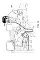
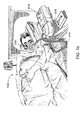
一実施形態において、本技術は呼吸器疾患を治療する装置を含むものとなっている。かかる装置は、患者用インターフェース3000に繋がる空気導管を介して空気等の加圧呼吸ガスを患者1000に供給するように構成される流れ生成器又は送風機を備えていてもよい。
[Treatment system]
In one embodiment, the technique includes a device for treating a respiratory disease. Such a device may include a flow generator or blower configured to supply a pressurized breathing gas, such as air, to the
[療法]
一実施形態において、本技術は、患者1000の気道の入口に陽圧を印加するステップを含む呼吸器疾患治療方法を含むものとなっている。
[Treatment]
In one embodiment, the technique comprises a method of treating a respiratory disease that includes the step of applying positive pressure to the entrance of the airway of
[OSA用経鼻CPAP]
一実施形態において、本技術は、患者に経鼻的持続気道陽圧を印加することによって患者の閉塞性睡眠時無呼吸を治療する方法を含むものとなっている。
[Nasal CPAP for OSA]
In one embodiment, the technique includes a method of treating obstructive sleep apnea in a patient by applying nasal continuous positive airway pressure to the patient.
本技術の特定の実施形態においては、1つ又は複数の鼻孔を介して、患者の鼻道に陽圧の空気が供給される。 In certain embodiments of the technique, positive pressure air is supplied to the patient's nasal passages through one or more nostrils.
[患者用インターフェース3000]
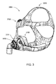
図3を参照すると、本技術の一態様に係る非侵襲的患者用インターフェース3000は、機能的態様、すなわち、密閉構造3100と、プレナム室3200と、位置決め・安定化構造3300と、空気回路4170に接続するための接続部とを備えている。いくつかの実施形態においては、1つ又は複数の物理的構成要素によって機能的態様がもたらされてもよい。また、いくつかの実施形態においては、1つの物理的構成要素によって1つ又は複数の機能的態様がもたらされてもよい。使用に際して、密閉構造3100は、患者の気道の入口を囲むことによって、陽圧の空気を気道に供給することを促すように構成されている。患者用インターフェース3000は、呼気の二酸化炭素を清浄化できるように構成及び配置された通気口3400を含んでいてもよい。また、患者用インターフェース3000が前頭支持部3700を含んでいてもよい。他の種類の患者用インターフェースがまた実現されてもよい。
[Patient Interface 3000]
Referring to FIG. 3, the
[PAP機器4000]
図4aを参照すると、PAP機器4000等の呼吸治療装置は、機械的空気圧構成要素4100及び電気的構成要素4200を含んでいてもよく、1つ又は複数のアルゴリズム4300(図4dに示す)を実行するようにプログラムされていてもよい。図4aの形式において示すように、PAP機器は、2つの部品により構成された外部ハウジング4010と、外部ハウジング4010の上部4012と、外部ハウジング4010の下部4014とを有している。別の実施形態においては、外部ハウジング4010が1つ又は複数のパネル4015を含んでいてもよい。PAP機器4000は、その1つ又は複数の内部構成要素を支持するように構成されるシャーシ部材4016を備えている。一実施形態においては、シャーシ部材4016によって空気圧ブロック機構4020が支持されているか、又はシャーシ部材4016の一部として空気圧ブロック機構4020が形成されている。PAP機器4000は取っ手部材4018を含んでいてもよい。
[PAP device 4000]
With reference to FIG. 4a, a respiratory therapy device such as the
図4bを参照すると、PAP機器4000の空気圧経路は、入口側空気フィルタ4112と、入口側マフラー4122と、陽圧の空気を供給可能に構成される制御可能な圧力機器4140(好ましくは、送風機4142)と、出力側マフラー4124とを備えている。空気圧経路には、1つ又は複数の圧力センサ及び流量センサが設置されている。
Referring to FIG. 4b, the air pressure path of the
空気圧ブロック機構4020には、外部ハウジング4010内に配置された空気圧経路の部分を含んでいてもよい。
The
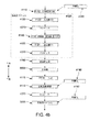
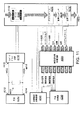
図4cを参照すると、PAP機器4000の電子的構成要素4200は、電源4210と、1つ又は複数の入力機器4220と、中央制御器4230と、治療機器用制御器4240と、治療機器4245と、1つ又は複数の保護回路4250と、メモリ4260と、トランスデューサ4270と、データ通信インターフェース4280と、1つ又は複数の出力機器4290とを含んでいてもよい。図4aに示すように、電気的構成要素4200は、単一のプリント基板組立体(PCBA)4202上に実装されてもよい。別の実施形態においては、PAP機器4000は、2つ以上のPCBA4202を含んでいてもよい。
Referring to FIG. 4c, the
図4dを参照すると、PAP機器4000の中央制御器4230は、一実施態様において、前処理モジュール4310と、治療用エンジンモジュール4320と、圧力制御モジュール4330と、障害状態検出モジュール4340とを含む1つ又は複数のアルゴリズム4300のモジュールを実行するようにプログラムされている。
Referring to FIG. 4d, the
本技術のいくつかの態様によれば、中央制御器4230は、任意選択的には、障害状態動作モジュール4340を省略していてもよい。それどころか、障害検出は、中央制御器4230とは別個の障害緩和用集積回路4500によって実行されてもよい。このような障害緩和用集積回路4500については、本明細書においてより詳しく説明する。
According to some aspects of the present technology, the
一実施形態において、PAP機器4000は、区別なく人工呼吸器と呼ばれることがある。
In one embodiment, the
[PAP機器の機械的空気圧構成要素4100]
[(1つ又は複数の)空気フィルタ4110]
図4bを参照すると、本技術の一実施形態に係るPAP機器は1つ又は複数の空気フィルタ4110を含んでいてもよい。
[Mechanical pneumatic component of PAP equipment 4100]
[(One or more) air filters 4110]
Referring to FIG. 4b, the PAP apparatus according to one embodiment of the present technology may include one or
一実施形態において、送風機4142の上流側の空気圧経路における始点には、入口側空気フィルタ4112が配置されている(図4b参照)。
In one embodiment, an
一実施形態において、空気圧ブロック機構4020の出口と患者用インターフェース3000との間には、抗菌フィルタ等の出口側空気フィルタ4114が配置されている(図4b参照)。
In one embodiment, an outlet-
[(1つ又は複数の)マフラー4120]
本技術の一実施形態において、入口側マフラー4122は、送風機4142の上流側の空気圧経路に配置されている(図4b参照)。
[(One or more) muffler 4120]
In one embodiment of the present technology, the inlet side muffler 4122 is arranged in the air pressure path on the upstream side of the blower 4142 (see FIG. 4b).
本技術の一実施形態において、出口側マフラー4124は、送風機4142と患者用インターフェース3000との間の空気圧経路に配置されている(図4b参照)。
In one embodiment of the present technology, the outlet side muffler 4124 is located in the pneumatic path between the
[圧力機器4140]
図4bを参照すると、本技術の一実施形態においては、陽圧の空気の流れを生成するように構成される圧力機器4140が制御可能な送風機4142となっている。例えば、送風機は、1つ又は複数のインペラを螺旋状に収容しているブラシレスDCモータ4144を含んでいてもよい。また、送風機は、例えば、約120リットル/分にて、約4cmH2O〜約20cmH2O、他の実施形態では、最大約30cmH2Oの範囲にある陽圧の空気を供給可能である。
[Pressure equipment 4140]
Referring to FIG. 4b, in one embodiment of the present technology, the
圧力機器4140は治療機器用制御器4240の制御下にある。
The
[(1つ又は複数の)トランスデューサ4270]
図4bを参照すると、本技術の一実施形態においては、圧力機器4140の上流側に1つ又は複数のトランスデューサ4270が配置されている。この1つ又は複数のトランスデューサ4270は、空気圧経路の当該地点における空気の特性を測定するように構成及び配置されている。
[(One or more) Transducers 4270]
Referring to FIG. 4b, in one embodiment of the present technology, one or
本技術の一実施形態においては、1つ又は複数のトランスデューサ4270が、圧力機器4140の下流側かつ空気回路4170の上流側に配置されている。この1つ又は複数のトランスデューサ4270は、空気圧経路の当該地点における空気の特性を測定するように構成及び配置されている。
In one embodiment of the technique, one or
本技術の一実施形態においては、1つ又は複数のトランスデューサ4270が、患者用インターフェース3000に近接して配置されている。
In one embodiment of the technique, one or
[逆流防止弁4160]
本技術の一実施形態においては、加湿器5000と空気圧ブロック機構4020との間に逆流防止弁が配置されている。逆流防止弁は、加湿器5000からモータ4144等に向かって上流側に水が流れるような危険性を減らすように構成及び配置されている。
[Check valve 4160]
In one embodiment of the present technology, a check valve is arranged between the
[空気回路4170]
図4bに示すように、本技術の一態様に係る空気回路4170は、空気圧ブロック機構4020と患者用インターフェース3000との間にて空気又は呼吸可能なガスが流れ得るように構成及び配置されている。
[Air circuit 4170]
As shown in FIG. 4b, the
[酸素の供給]
引き続き図4bを参照すると、本技術の一実施形態においては、空気圧経路のある地点に予備酸素4180が供給される。
[Oxygen supply]
Continuing with reference to FIG. 4b, in one embodiment of the present technology,
本技術の一実施形態においては、予備酸素4180は、空気圧ブロック機構4020の上流側に供給される。
In one embodiment of the present technology, the
本技術の一実施形態においては、予備酸素4180は、空気回路4170に供給される。
In one embodiment of the present technology, the
本技術の一実施形態においては、予備酸素4180は、患者用インターフェース3000に供給される。
In one embodiment of the technique, the
[PAP機器の電気的構成要素4200]
[基本PAP機器]
[電源4210]
図4cを参照すると、電源4210は、基本PAP機器4000の他の構成要素、すなわち、入力機器4220と、中央制御器4230と、治療機器4245と、出力機器4290とに電力を供給するようになっている。
[Electrical component of PAP equipment 4200]
[Basic PAP equipment]
[Power supply 4210]
Referring to FIG. 4c, the
本技術の一実施形態において、電源4210は、PAP機器4000の外部ハウジング4010の内部に設けられている。本技術の別の実施形態においては、電源4210は、PAP機器4000の外部ハウジング4010の外部に設けられている。
In one embodiment of the present technology, the
電源4210は、負の再生電流を遮断可能に構成される商用電源用スイッチング電源を含んでいてもよい。
The
[(1つ又は複数の)入力機器4220]
入力機器4220(図4cに示す)は、PAP機器4000を人と相互作用することを可能にすべく、ボタン、スイッチ、ダイヤルのうち1つ又は複数を含んでいてもよい。ボタン、スイッチ、又はダイヤルは、物理的機器であってもよいし、タッチスクリーンを介してアクセス可能に構成されるソフトウェア機器であってもよい。ボタン、スイッチ、又はダイヤルは、一実施形態においては、外部ハウジング4010に対して物理的に接続されていてもよいし、別の実施形態においては、中央制御器4230に対して電気的に接続された受信機と無線通信するようになっていてもよい。
[(One or more) input devices 4220]
The input device 4220 (shown in FIG. 4c) may include one or more of buttons, switches, dials to allow the
一実施形態においては、入力機器4220は、人によって値及び/又はメニューオプションが選択可能となるように構成及び配置されていてもよい。
In one embodiment, the
[中央制御器4230]
本技術の一実施形態において、中央制御器4230(図4cに示す)は、入力機器4220から(1つ又は複数の)入力信号を受信すると共に、(1つ又は複数の)出力信号を出力機器4290及び/又は治療機器制御器4240に与えるように構成された専用の電子回路となっている。
[Central controller 4230]
In one embodiment of the present technology, the central controller 4230 (shown in FIG. 4c) receives (one or more) input signals from the
一実施形態においては、中央制御器4230は特定用途向けの集積回路となっている。別の実施形態においては、中央制御器4230に、個別の電子的構成要素が形成されてもよい。
In one embodiment, the
[治療機器4245]
本技術の一実施形態において、治療機器4245(図4cに示す)は、中央制御器4230の制御下において、患者1000に治療を施すように構成されている。また、治療機器4245は、空気陽圧機器4140等の制御可能な圧力機器4140であってもよい。
[Treatment equipment 4245]
In one embodiment of the technique, the treatment device 4245 (shown in FIG. 4c) is configured to treat
[出力機器4290]
本技術に係る出力機器4290(図4cに示す)は、視覚出力機器、音響出力機器、及び触覚出力機器のうち1つ又は複数の形態であってもよい。視覚出力機器は、液晶ディスプレイ(LCD)又は発光ダイオード(LED)ディスプレイであってもよい。音響出力機器は、スピーカ又は音声階調放出機器であってもよい。
[Output device 4290]
The output device 4290 (shown in FIG. 4c) according to the present technology may be in the form of one or more of a visual output device, an acoustic output device, and a tactile output device. The visual output device may be a liquid crystal display (LCD) or a light emitting diode (LED) display. The sound output device may be a speaker or a sound gradation emitting device.
[マイクロプロセッサ制御PAP機器]
[電源4210]
本技術の一実施形態において、電源4210(図4cに示す)は、PAP機器4000の外部ハウジング4010の内部に設けられている。本技術の別の実施形態においては、電源4210は、PAP機器4000の外部ハウジング4010の外部に設けられている。
[Microprocessor-controlled PAP device]
[Power supply 4210]
In one embodiment of the present technology, the power supply 4210 (shown in FIG. 4c) is provided inside the outer housing 4010 of the
本技術の一実施形態において、電源4210は、PAP機器4000のみに電力を供給するようになっている。本技術の別の実施形態においては、電源4210は、PAP機器4000及び加湿器5000の両方に電力を供給するようになっている。
In one embodiment of the present technology, the
[入力機器4220]
本技術の一実施形態において、PAP機器4000は、当該機器を人と相互作用することを可能にすべく、ボタン、スイッチ、ダイヤルの形態のうち1つ又は複数の入力機器4220(図4cに示す)を含んでいる。ボタン、スイッチ、又はダイヤルは、物理的機器であってもよいし、タッチスクリーンを介してアクセス可能に構成されるソフトウェア機器であってもよい。ボタン、スイッチ、又はダイヤルは、一実施形態において、外部ハウジング4010に対して物理的に接続されていてもよいし、別の実施形態においては、中央制御器4230に対して電気的に接続された受信機と無線通信するようになっていてもよい。
[Input device 4220]
In one embodiment of the present technology, the
一実施形態においては、入力機器4220が、人によって値及び/又はメニューオプションが選択可能となるように構成及び配置されていてもよい。
In one embodiment, the
[中央制御器4230]
本技術の一実施形態において、中央制御器4230(図4cに示す)は、x86 INTELプロセッサ等のように、PAP機器4000の制御に適したプロセッサ又はマイクロプロセッサであってもよい。
[Central controller 4230]
In one embodiment of the present technology, the central controller 4230 (shown in FIG. 4c) may be a processor or microprocessor suitable for controlling the
本技術の別の実施形態に係るPAP機器4000の制御に適した中央制御器4230は、ARM HoldingsのARM Cortex−Mプロセッサに基づくプロセッサを含んでいてもよい。例えば、ST MICROELECTRONICSのSTM32シリーズマイクロコントローラを用いてもよい。
A
本技術のさらに別の実施形態において、中央制御器4230は、ARM9ベースの32ビットRISC CPUのファミリから選択される1つを含んでいてもよい。例えば、ST MICROELECTRONICSのSTR9シリーズマイクロコントローラを用いてもよい。
In yet another embodiment of the technique, the
本技術における別の特定の実施形態では、PAP機器4000の中央制御器4230として16ビットRISC CPUを用いてもよい。例えば、TEXAS INSTRUMENTS製のMSP430マイクロコントローラファミリのプロセッサを用いてもよい。
In another particular embodiment of the art, a 16-bit RISC CPU may be used as the
中央制御器4230は、1つ又は複数のトランスデューサ4270及び1つ又は複数の入力機器4220から(1つ又は複数の)入力信号を受信するように構成されてもよい。
The
中央制御器4230は、出力機器4290、治療機器用制御器4240、データ通信インターフェース4280、及び加湿器用制御器5250のうち1つ又は複数に対して、(1つ又は複数の)出力信号を与えるように構成されている。
The
中央制御器4230又は複数のそのようなプロセッサは、メモリ4260等のコンピュータ読取可能記憶媒体に格納されたコンピュータプログラムとして表される1つ又は複数のアルゴリズム4300(図4dに示す)等のように、本明細書に記載の1つ又は複数の方法を実施するように構成されている。場合によっては、上記の通り、(1つ又は複数の)このようなプロセッサがPAP機器4000と統合されてもよい。ただし、いくつかの機器においては、呼吸治療の提供を直接的に制御することなく本明細書に記載の方法のいずれかを実施すること等を目的として、PAP機器の流れ生成構成要素とは個別に(1つ又は複数の)プロセッサが実装されてもよい。例えば、このようなプロセッサは、本明細書に記載のいずれかのセンサ等からの格納データの分析によって人工呼吸器又は他の呼吸関連事象の制御設定を決定することを目的として、本明細書に記載の方法のいずれかを実施するようになっていてもよい。
The
[クロック4232]
PAP機器4000は、プロセッサ又は中央制御器4230に接続されたクロック4232(図4cに示す)を含んでいると好ましい。
[Clock 4232]
The
[治療機器用制御器4240]
本技術の一実施形態において、治療機器用制御器4240(図4cに示す)は、中央制御器4230による実行又は中央制御器4230と協働した実行が成されるようなアルゴリズム4300の特徴を実装可能な治療制御モジュール4330(図4dに示す)となっている。場合により、治療機器用制御器4240には、モータ駆動部が実装されてもよい。
[Control for treatment equipment 4240]
In one embodiment of the technique, the therapeutic device controller 4240 (shown in FIG. 4c) implements the features of
本技術の一実施形態において、治療機器用制御器4240は、専用のモータ制御集積回路となっている。例えば、一実施形態においては、ONSEMI製のMC33035ブラシレスDCモータ用制御器が用いられる。
In one embodiment of the present technology, the
[保護回路4250]
本技術に係るPAP機器4000は、図4cに示すような1つ又は複数の保護回路4250を含んでいると好ましい。
[Protection circuit 4250]
The
本技術に係る保護回路4250の一実施形態は、電気保護回路とすることができる。
One embodiment of the
本技術に係る保護回路4250の一実施形態は、温度又は圧力安全回路とすることができる。
One embodiment of the
本技術のいくつかの形式において、保護回路4250が過渡吸収ダイオード回路4400を含んでいてもよい。この回路は、送風機モータ等からの回転運動エネルギーから生成又は変換されたエネルギーを吸収するように構成されていてもよい。本技術の別の実施態様によれば、保護回路4250は、障害緩和用集積回路4500(図8及び図9に示す単一のIC回路等)を含んでいてもよい。過渡吸収ダイオード回路4400及び障害緩和用集積回路4500に関する特定の実施形態については、本明細書においてより詳しく論じる。
In some forms of the art, the
[メモリ4260]
本技術の一実施形態によれば、PAP機器4000は、メモリ4260(図4cに示す)、好ましくは、不揮発性メモリを含んでいる。いくつかの実施形態においては、メモリ4260が電池式のスタティックRAMを含んでいてもよい。いくつかの実施形態においては、メモリ4260が揮発性RAMを含んでいてもよい。
[Memory 4260]
According to one embodiment of the present technology, the
メモリ4260は、PCBA4202(図4aに示す)上に配置されると好ましい。また、メモリ4260は、EEPROM又はNANDフラッシュの形態であってもよい。
The
このことに対する追加又は代替として、PAP機器4000が、セキュアデジタル(SD)規格に従って構成されたメモリカード等のような着脱式のメモリ4260を含んでいてもよい。
As an addition or alternative to this, the
本技術の一実施形態において、メモリ4260は、1つ又は複数のアルゴリズム4300等のように、本明細書に記載の1つ又は複数の方法を表すコンピュータプログラム命令を格納したコンピュータ読取可能記憶媒体として作用するものとなっている。
In one embodiment of the present technology, the
[トランスデューサ4270]
トランスデューサ4270(図4cに示す)は、PAP機器の内部に設けられてもよいし、外部に設けられてもよい。外部のトランスデューサは、例えば、空気供給回路及び/又は患者用インターフェース上に配置されていてもよいし、空気供給回路及び/又は患者用インターフェースの一部を構成していてもよい。また、外部のトランスデューサは、データをPAP機器に送信又は転送するドップラーレーダ移動センサ等の非接触式センサの形態であってもよい。
[Transducer 4270]
The transducer 4270 (shown in FIG. 4c) may be provided inside or outside the PAP device. The external transducer may be located, for example, on the air supply circuit and / or the patient interface, or may form part of the air supply circuit and / or the patient interface. Further, the external transducer may be in the form of a non-contact sensor such as a Doppler radar movement sensor that transmits or transfers data to a PAP device.
[流量]
本技術に係る流量トランスデューサ4274(図4cに示す)は、SENSIRIONのSDP600シリーズ差圧トランスデューサ等の差圧トランスデューサに基づいていてもよい。差圧トランスデューサは、それぞれが流量制限要素の第1及び第2の接点に接続された状態で空気圧回路と流体連通している。
[Flow rate]
The flow rate transducer 4274 (shown in FIG. 4c) according to the present technology may be based on a differential pressure transducer such as SENSIRION's SDP600 series differential pressure transducer. The differential pressure transducers fluidly communicate with the pneumatic circuit, each connected to the first and second contacts of the flow limiting element.
使用時においては、流量トランスデューサ4274からの総流量Qtを表す信号を中央制御器4230が受信する。ただし、このような流量信号の生成又は流量の推定を行う他のセンサが実装されてもよい。例えば、いくつかの実施形態においては、熱線質量流量センサ等の質量流量センサの実装によって、流量信号が生成されてもよい。任意選択的には、流量は、米国特許出願第12/192,247号に記載の方法等のいずれかに従って、本明細書に記載の他のセンサの1つ又は複数の信号から推定されてもよく、その開示内容は、それを参照することによって本明細書に組み入れられるものとする。
In use, the
[圧力]
本技術に係る圧力トランスデューサ4272(図4cに示す)は、空気圧回路と流体連通するように配置されてもよい。適切な圧力トランスデューサの一例は、HONEYWELL ASDXシリーズのセンサであるとよい。別の適切な圧力トランスデューサは、GENERAL ELECTRICのNPAシリーズのセンサであるとよい。
[pressure]
The
使用時においては、圧力トランスデューサ4272からの信号を中央制御器4230が受信する。一実施形態においては、圧力トランスデューサ4272からの信号は、中央制御器4230により受信される前にフィルタリングされる。
In use, the
[モータ速度]
本技術の一実施形態においては、モータ速度トランスデューサ4276(図4cに示す)からのモータ速度信号が生成される。モータ速度信号は、治療機器制御器4240によって与えられると好ましい。モータ速度は、例えば、ホール効果センサ等の速度センサによって生成されてもよい。
[Motor speed]
In one embodiment of the present technology, a motor speed signal is generated from a motor speed transducer 4276 (shown in FIG. 4c). The motor speed signal is preferably given by the
[温度]
温度トランスデューサ4278(図4cに示す)は、空気圧回路のガスの温度を測定するように構成されてもよい。温度トランスデューサ4278の一例としては、熱電対又は抵抗温度検出器(RTD)が挙げられる。
[temperature]
The temperature transducer 4278 (shown in FIG. 4c) may be configured to measure the temperature of the gas in the pneumatic circuit. An example of a
[データ通信システム]
本技術の好適な一実施形態においては、データ通信インターフェース4280(図4cに示す)が設けられ、これが中央制御器4230に接続されている。データ通信インターフェース4280は、リモート外部通信ネットワーク4282に接続可能であると好ましい。また、データ通信インターフェース4280は、ローカル外部通信ネットワーク4284に接続可能であると好ましい。リモート外部通信ネットワーク4282は、リモート外部機器4286に接続可能であると好ましい。ローカル外部通信ネットワーク4284は、ローカル外部機器4288に接続可能であると好ましい。
[Data communication system]
In a preferred embodiment of the present technology, a data communication interface 4280 (shown in FIG. 4c) is provided, which is connected to the
一実施形態においては、データ通信インターフェース4280が中央制御器4230の一部となっている。別の実施形態においては、データ通信インターフェース4280が、中央制御器4230とは別個の集積回路となっている。
In one embodiment, the
一実施形態においては、リモート外部通信ネットワーク4282がインターネットとなっている。データ通信インターフェース4280は、有線通信(例えば、イーサネット(登録商標)又は光ファイバ経由)又は無線プロトコルを用いてインターネットに接続するようになっていてもよい。
In one embodiment, the remote external communication network 4482 is the Internet. The
一実施形態においては、ローカル外部通信ネットワーク4284が、Bluetooth(登録商標)等の1つ若しくは複数の通信規格又はコンシューマ赤外線プロトコルを利用するようになっている。
In one embodiment, the local
一実施形態においては、リモート外部機器4286が、ネットワークコンピュータのクラスタ等のような1つ又は複数のコンピュータとなっている。一実施形態においては、リモート外部機器4286が、物理コンピュータではなく仮想コンピュータであってもよい。いずれにしても、このようなリモート外部機器4286は、臨床医等のような適切な許可を得た人が利用し易いものであるとよい。
In one embodiment, the remote
ローカル外部機器4288は、パーソナルコンピュータ、携帯電話、タブレット、又はリモコンであると好ましい。
The local
[任意選択的にディスプレイ、アラームを含む出力機器]
本技術に係る出力機器4290(図4cに示す)は、視覚ユニット、音声ユニット、及び触覚ユニットのうち1つ又は複数の形態であってもよい。視覚表示機器は、液晶ディスプレイ(LCD)又は発光ダイオード(LED)ディスプレイであってもよい。
[Output equipment including display and alarm arbitrarily]
The output device 4290 (shown in FIG. 4c) according to the present technology may be in the form of one or more of a visual unit, an audio unit, and a tactile unit. The visual display device may be a liquid crystal display (LCD) or a light emitting diode (LED) display.
[ディスプレイドライバ4292]
ディスプレイドライバ4292(図4cに示す)は、ディスプレイ4294への表示を意図した文字、記号、又は画像の入力を受けて、ディスプレイ4294にこれらの文字、記号、又は画像を表示させるコマンドに変換するようになっている。
[Display driver 4292]
The display driver 4292 (shown in FIG. 4c) receives input of characters, symbols, or images intended to be displayed on the
[ディスプレイ4294]
ディスプレイ4294(図4cに示す)は、ディスプレイドライバ4292から受信したコマンドに応答して、文字、記号、又は画像を視覚表示するように構成されている。例えば、ディスプレイ4294は、8セグメントディスプレイであってもよく、この場合、ディスプレイドライバ4292は、数字「0」等の各文字又は記号を、8つの各セグメントを有効にして特定の文字又は記号を表示するか否かを示す8つの論理信号に変換するようになっている。
[Display 4294]
The display 4294 (shown in FIG. 4c) is configured to visually display characters, symbols, or images in response to commands received from the
[過渡吸収ダイオード回路4400]
本技術のいくつかの態様によれば、保護回路4250は、モータ4144の制動又は急減速時に生じる電圧及び/又は電流等のような過剰なエネルギーを吸収する運動エネルギー吸収回路を含んでいてもよい。このようなエネルギーは、制動又は急減速時のモータの回転運動エネルギーにより生成又は再生される場合がある。
[Transient absorption diode circuit 4400]
According to some aspects of the technique, the
一例として、PAP機器が定常状態にある場合、モータ4144は、特定の速度で動作するように構成されていてもよい。この状態で、モータ4144は、印加された負荷及び内部損失に比例して、電源4210により供給された電力を消費するようになっていてもよい。このプロセスにおいて、モータ4144は、電源4210により供給された電気エネルギー、すなわち、電力を回転運動エネルギーに変換するようになっている。
As an example, when the PAP device is in steady state, the motor 4144 may be configured to operate at a particular speed. In this state, the motor 4144 may consume the power supplied by the
モータ4144は、急減速又は制動時に、過渡期間に渡ってエネルギー変換を反転するようになっている。例えば、モータ4144は、急減速又は制動時に、回転方向と反対の方向に与えられた回転運動エネルギーの結果としてエネルギーを生成するようになっている。モータ4144は、急減速又は制動時に、回転運動エネルギーを電気エネルギーに変換する。通常では、これによって、電源4210及びモータ4144間のバス又は回路ライン上の電圧又は電流が急上昇する。このような電圧及び/又は電流の上昇を防止すべく、電源4210及びモータ4144間のバス又は回路ラインには、運動エネルギー吸収回路が配置されてもよい。
The motor 4144 is adapted to reverse the energy conversion over a transient period during sudden deceleration or braking. For example, the motor 4144 is adapted to generate energy as a result of rotational kinetic energy given in a direction opposite to the rotational direction during sudden deceleration or braking. The motor 4144 converts rotational kinetic energy into electrical energy during sudden deceleration or braking. Normally, this causes a spike in voltage or current on the bus or circuit line between the
一実施形態においては、運動エネルギー吸収回路が、図6に示す構成等のような過渡吸収ダイオード回路4400であってもよい。図6は、例示的なPAP機器4000の態様の模式図である。図6に示すように、過渡吸収ダイオード回路4400は、電源4210及びモータ4144間に実装されてもよく、例えば、電源4210とインバータブリッジ回路4410等のブリッジ回路との間に実装されてもよい。
In one embodiment, the kinetic energy absorption circuit may be a transient
インバータブリッジ回路4410は電子回路となっている。このような回路によって、モータ4144の両方向に1つ又は複数の電圧レベルを印加することにより、モータ4144の加速又は減速が可能であってもよい。例えば、インバータブリッジ回路4410には、1つ又は複数のスイッチング要素(例えば、トランジスタ又はMOSFET)が実装されてもよい。モータ4144の動作は、モータの加速又は減速等を行う異なるスイッチの開放又は閉鎖の制御によって設定されてもよい。例えば、インバータブリッジ回路4410は、モータの逆起電力(EMF)電圧を下回るレベルまでモータの有効電圧を下げることによって、モータ4144の制動又は急減速を行うように構成されてもよい。このプロセスによって、電流の方向が反転して、電流がインバータブリッジ回路4410から電源4210へと流れる。より具体的には、モータの制動のために、負の有効電圧がモータに誘導される。負の有効電圧によって、電流が反転して電源4210及びモータ4144間のバス又は回路ライン上に逆流し、その結果、バス又は回路ライン上の電圧レベルが上昇する。また、インバータブリッジ回路4410は、モータとPAP機器4000のその他の電子的構成要素(例えば、治療機器用制御器及び/又は中央制御器)との間に電流信号等の制御接続を含んでいてもよい。
The
図6に示すように、インバータブリッジ回路は、治療機器用制御器4240によって制御されるようになっていてもよい。上述の通り、治療機器用制御器4240は、中央制御器4230により実行されるアルゴリズムのプロセスの一部を実装した治療制御モジュールであってもよい。例えば、図6に示すように、中央制御器4230は、圧力トランスデューサ4272、流量トランスデューサ4274、及び温度トランスデューサ4278からそれぞれ受信した圧力、流量、及び温度測定結果等の1つ又は複数の入力信号に基づく実行可能命令を与えることによって、治療機器用制御器4240の動作を制御するように構成されてもよい。これらのトランスデューサは、送風機4142の出口4432の近接位置等のような送風機4142に対する様々な位置にて、空気圧経路における呼吸可能なガスの流れの特性を測定するように位置決めされてもよい。
As shown in FIG. 6, the inverter bridge circuit may be controlled by the
また、中央制御器4230は、治療機器用制御器4240からモータ速度を受信するように構成されてもよい。1つ又は複数の様々な入力に応じて、中央制御器4230は、モータブリッジの制御に基づいてモータ4144に供給される電流又は電圧の変更を治療機器用制御器4240に指示することによって、送風機4142の出力を調節するように構成されてもよい。
Further, the
引き続き図6を参照すると、本技術の一態様によれば、過渡吸収ダイオード回路4400は、電源4210とインバータブリッジ回路4410との間に配置されてもよい。具体的には、図6に示すように、電源4210の第1の端子4212が第1のライン4422(例えば、ワイヤ又は信号線)によってインバータブリッジ回路4410の第1の端子4412に接続され、電源4210の第2の端子4214が第2のライン4424によってインバータブリッジ回路4410の第2の端子4414に接続されるように、電源4210がインバータブリッジ回路4410に接続されてもよい。場合によっては、第1のライン4422が直流(DC)バス又はラインである一方、第2のライン4424が接地ラインであってもよいし、その逆も可能である。
Continuing with reference to FIG. 6, according to one aspect of the present technology, the transient
図6に示すように、過渡吸収ダイオード回路4400は、当該過渡吸収ダイオード回路4400の第1の端子4402が第1のライン4422に接続されると共に当該過渡吸収ダイオード回路4400の第2の端子4404が第2のライン4424に接続されるように、電源4210とインバータブリッジ回路4410との間に配置されている。
As shown in FIG. 6, in the transient
一実施形態によれば、過渡吸収ダイオード回路4400は、1つ又は2つ以上の過渡吸収ダイオード4420を含んでいてもよい。過渡吸収ダイオード4420の例としては、数ある可能性の中で特に、過渡電圧抑制(TVS)ダイオード及びTransil(商標)が挙げられる。過渡吸収ダイオード4420は、互いに直列又は並列に接続されることによって、一体的に、第1のライン4422及び第2のライン4424に跨る電圧クランプとして機能するようになっていてもよい。特に、過渡吸収ダイオード4420を互いに直列に接続することによって、各過渡吸収ダイオード4420において、エネルギー吸収をより均一に分散させることができる。図6に示す例においては、第1のライン4422及び第2のライン4424に跨って、2つの過渡吸収ダイオード4420(例えば、過渡電圧抑制ダイオード)が直列に接続されている。再生エネルギーの増加を取り扱う必要に応じて、過渡吸収ダイオード回路4400には、別の過渡吸収ダイオード4420が追加されてもよい。
According to one embodiment, the transient
このような構成によって、モータ4144の制動又は急減速時に生成されたエネルギーは、過渡吸収ダイオード回路4400へと放出又は転流される。この点について、過渡吸収ダイオードは、通常、数十マイクロ秒オーダ等の極短時間に渡る非常に高いエネルギーの外部の破壊的なスパイクを吸収するものであると解釈できる。それでもなお、本技術の通常の用途においては、(例えば、流れ生成器のモータからの)エネルギーのスパイクが100ミリ秒オーダ等の長い時間に渡って継続する場合であってもそのエネルギー量がはるかに小さければ、過渡吸収ダイオード回路4400がそのスパイクを抑制するように機能してもよいことが決まっている。過渡吸収ダイオード回路4400は、例えば、当該回路4400の分岐合流点において温度が許容限界を超えることなく、長い時間に渡ってエネルギーのスパイクを抑制できるように、所定の速度でエネルギーを吸収するように構成されてもよい。直列接続された2つ以上の過渡吸収ダイオード4420を使用することによって、プリント基板(PCB)のより多くの銅にエネルギー散逸負荷、ひいては、熱が拡がり、その結果として、回路4400の分岐合流点における温度が許容限界内に維持されるようになっていてもよい。
With such a configuration, the energy generated during braking or sudden deceleration of the motor 4144 is released or commutated to the transient
図7に示すように、本技術の別の実施形態によれば、過渡吸収ダイオード回路4400は、過渡吸収ダイオード4420の他、1つ又は複数の蓄電器4421を含んでいてもよい。この1つ又は複数の蓄電器4421は、例えば、並列に互いに接続されてもよい。また、この1つ又は複数の蓄電器4421は、順次接続された過渡吸収ダイオード4420によって、例えば、並列に接続されてもよい。この1つ又は複数の蓄電器4421は、モータ4144の制動又は急減速時に生成されたエネルギーの少なくとも一部を蓄積するように機能してもよい。そして、蓄積されたエネルギーは、モータ等の回路のパワー構成要素に再利用されてもよい。
As shown in FIG. 7, according to another embodiment of the present technology, the transient
[過渡吸収ダイオード回路4400の潜在的な利点]
このような過渡吸収ダイオード回路については、複数の利点が考えられる。例えば、過渡吸収ダイオード回路4400は、モータの制動又は急減速時に生成された運動再生エネルギーに対処するコスト効率の高い簡単な手法を提供するようになっていてもよい。
[Potential advantages of transient absorption diode circuit 4400]
There are several possible advantages for such a transient absorption diode circuit. For example, the transient
例えば、過渡吸収ダイオード回路4400は、実装し得るより高価なスイッチトレジスタ負荷又はスイッチトレジスタ回路の代替として機能するようになっていてもよい。このようなスイッチトレジスタ負荷又はスイッチトレジスタ回路においては、一般的に、非常に大きなプリント基板(PCB)設置領域が必要となり、構成要素のコスト、労力、及び開発時間の大幅な増加が必要となる。さらに、スイッチトレジスタ回路法では、制御回路が必要であり、複雑性、コスト、及び故障モードが増大する場合がある。ただし、過渡吸収ダイオード回路を使用する場合、このような制御回路は不要である。スイッチトレジスタ負荷又はスイッチトレジスタ回路を過渡吸収ダイオード回路4400に置き換えることによって、PCB設置領域、労力、開発時間が大幅に抑えられるため、商品としてのコスト又は機器当たりのコストが大幅に低くなる可能性がある。
For example, the transient
[障害緩和用集積回路4500]
本技術の一態様によれば、保護回路4250は、単一の集積回路又はチップを含んでいてもよい。このようなチップは、障害検出を実行するように構成されてもよい。このような集積回路の動作は、中央制御器4230とは独立かつ別個であってもよい。ただし、このような回路は、障害情報(例えば、1つ又は複数の出力信号)を中央制御器4230に与えるように構成されてもよい。また、このような集積回路は、障害緩和用集積回路(IC)4500として機能するようになっていてもよい。このような構成要素の一例を図8及び図9に示す。
[Integrated circuit for fault mitigation 4500]
According to one aspect of the technique, the
いくつかの形式においては、障害緩和IC4500が、混合型の単一チップとなっていてもよい。このようなチップは、アナログ及びデジタル入力信号であるとよい1つ又は複数の信号を受信するように構成されている。障害緩和IC4500により受信される(1つ又は複数の)入力信号は、PAP機器4000の1つ又は複数の物理又はシステムパラメータを表していてもよい。このような物理又はシステムパラメータとしては、モータ電流、モータバス電圧、モータ速度、圧力測定結果、流量測定結果、温度測定結果、及びシステムリセット信号のうち1つ又は複数が挙げられるが、これらに限定されない。
In some forms, the
障害緩和IC4500は、物理又はシステムパラメータのうち1つ又は複数に依拠することによって、任意の望ましくない状態又は潜在的に危険な状態、すなわち、障害が存在するか否かを検出するように構成されてもよい。障害緩和IC4500は、PAP機器4000に関して、数ある可能性の中で特に、(a)ゼロ電力又は不十分な電力等の停電、(b)推奨範囲外の動作パラメータ(例えば、圧力、流量、温度、又はPaO2測定結果)、(c)試験アラームによる検出可能なアラーム信号の生成ミス、(d)例えば、圧力トランスデューサ4272、流量トランスデューサ4274、モータ速度トランスデューサ4276、及び温度トランスデューサ4278等のトランスデューサのいずれかに関する異常、並びに(e)構成要素の有無の検出ミス等のような様々な種類の障害を検出する構成であるとよいが、これらに限定されない。
The fault mitigation IC4500 is configured to detect any unwanted or potentially dangerous condition, ie, the presence or absence of a fault, by relying on one or more of the physical or system parameters. You may. The
障害緩和IC4500は、障害を検出したら、1つ又は複数の信号(例えば、デジタル及び/又はアナログ)を生成して、重要なハードウェアを停止するように構成されてもよい。このような重要なハードウェアの例としては、数ある可能性の中で特に、送風機4142、モータ4144、インバータブリッジ回路4410、及び治療機器用制御器4240のうち1つ又は複数が挙げられる。このことに対する追加又は代替として、障害緩和IC4500は、障害を検出した場合、当該検出した障害を表す情報を(例えば、デジタル割り込み信号の送信によって)中央制御器4230に報告するように構成されてもよい。
The
図8〜図11を参照すると、障害緩和IC4500は、一般的に、信号を受信及び出力する入力ピン及び出力ピン、受信信号の評価に基づいて障害を判定する機構を実装したプログラマブルロジック、並びに1つ若しくは複数の計時器のような構成要素のうち1つ又は複数を含んでいてもよい。以下、各構成要素を詳細に論じる。
Referring to FIGS. 8-11, the
[入力ピン]
障害緩和IC4500は、図8及び図9に示す8つの入力ピン等のような任意数の入力ピンを含んでいてもよい。また、障害緩和IC4500は、入力ピンのうちの1つ又は複数を介して、アナログ及びデジタル入力信号を受信するように構成されてもよい。入力ピンのうち1つ又は複数は、機器4000における1つ又は複数の構成要素に接続されることによって、当該機器4000の物理又はシステムパラメータを受信するようになっていてもよい。例えば、機器4000の様々な構成要素との接続によって、入力ピンは、モータ電流、モータバス電圧、モータ速度、圧力測定結果、流量測定結果、温度測定結果、及びシステムリセット信号等の入力信号を受信するようになっていてもよい。
[Input pin]
The
さらに一例として、図11に示すように、入力ピン「IN1」は、治療機器用制御器4240に接続されることによって、モータ4144に供給された電流、すなわち、要求電流信号又はモータ電流信号を受信するようになっていてもよい。また、入力ピン「IN2」及び「IN3」についても、治療機器用制御器4240に接続されることによって、モータバス電圧信号及びモータ速度信号をそれぞれ受信するようになっていてもよい。入力ピン「IN4」は、圧力トランスデューサ4272に接続されることによって、圧力測定結果信号を受信するようになっていてもよい。入力ピン「IN5」は、流量トランスデューサ4274に接続されることによって、流量測定結果信号を受信するようになっていてもよい。入力ピン「IN6」は、温度トランスデューサ4278に接続されることによって、温度測定結果信号を受信するようになっていてもよい。入力ピン「IN7」は、システムリセット信号を受信するように構成されていてもよい。システムリセット信号は、入力機器4220(図11には示さず)又は中央制御器4230によって与えられるようになっていてもよい。
As a further example, as shown in FIG. 11, the input pin “IN1” receives the current supplied to the motor 4144 by being connected to the
図8〜図11に示す入力ピンの数は説明上の便宜的なものに過ぎない。実際には、障害緩和IC4500は、実施態様の様々な必要性又は複雑性に基づいて、任意数の入力ピンを含んでいてもよく、図示の数に必ずしも限定されない。
The numbers of input pins shown in FIGS. 8 to 11 are for convenience of explanation only. In practice, the
[出力ピン]
図8〜図11を参照すると、障害緩和IC4500は、8つの出力ピン等のような任意数の出力ピンを含んでいてもよい。また、障害緩和IC4500は、出力ピンのうち1つ又は複数を介して、アナログ及び/又はデジタル信号を生成するように構成されてもよい。いくつかの実施形態において、各出力ピンは、2進値を表す論理出力を生成するようになっていてもよい。出力ピンの論理出力がhighの場合、当該出力ピンにより与えられる対応2進値は「1」と見なすことができる。これに対して、出力ピンの論理出力がlowの場合、当該出力ピンにより与えられる対応2進値は「0」と見なすことができる。
[Output pin]
Referring to FIGS. 8-11, the
障害緩和IC4500は、チップのプログラム論理等に従って障害を検出した場合は、中央制御器等のソフトウェアを介在させることなく、1つ又は複数の出力信号によって、機器4000の重要なハードウェアのうち一部又は全部を直接制御するように構成されてもよい。また、障害緩和IC4500は、1つ又は複数の出力信号によって、検出した障害を中央制御器4230に報告するように構成されてもよい。場合により、障害緩和IC4500は、同じ出力信号を実装することによって、機器4000の重要なハードウェアを制御すると共に、障害情報を中央制御器4230に報告するように構成されてもよい。
When the fault mitigation IC4500 detects a fault according to the program logic of the chip, it uses one or more output signals without intervening software such as a central controller, and is a part of the important hardware of the
例えば、いくつかの実施形態においては、障害緩和IC4500が、障害を検出した場合、「OUT1」等のデジタル出力ピンを介して停止信号(割り込み信号とも呼び得る)を出力すると共に、「OUT2」、「OUT3」、及び「OUT4」等の1つ又は複数の他の出力ピンを介して、検出した障害の種類を出力するように構成されてもよい。 For example, in some embodiments, when the fault mitigation IC4500 detects a fault, it outputs a stop signal (which may also be called an interrupt signal) via a digital output pin such as "OUT1" and "OUT2", It may be configured to output the detected fault type via one or more other output pins such as "OUT3" and "OUT4".
例えば、障害が一切検出されていない場合、出力ピン「OUT1」の論理出力は、2進値「0」にてlowに設定されるようになっていてもよい。そして、機器4000は、この状況下で正常動作するようになっていてもよい。障害が検出された場合、出力ピン「OUT1」の論理出力は、2進値「1」にてhighに設定され、停止信号を出力するようになっていてもよい。
For example, when no failure is detected, the logical output of the output pin “OUT1” may be set to low at the binary value “0”. Then, the
出力ピン「OUT1」の論理出力は、複数の目的を果たすようになっていてもよい。例えば、出力ピン「OUT1」は、治療機器用制御器4240に接続されてもよい。出力ピン「OUT1」の論理出力が障害緩和IC4500によってlowに設定されている場合、治療機器用制御器4240、インバータブリッジ回路4410、及びモータ4144は、それぞれの動作を正常通りに継続するようになっていてもよい。ただし、出力ピン「OUT1」の論理出力が障害緩和IC4500によってhighに設定された場合、言い換えると、停止信号が生成されている場合、治療機器用制御器4240は、これに応じてモータ4144の動作を停止するように動作してもよい。この構成の利点として、ソフトウェアプロセスを一切呼び出すことなく、重要なハードウェア構成要素(モータ4144等)を停止可能とすることが挙げられる。場合により、出力ピン「OUT1」は、デジタル信号を出すようになっていてもよい。
The logical output of the output pin "OUT1" may serve a plurality of purposes. For example, the output pin “OUT1” may be connected to the
また、出力ピン「OUT1」は中央制御器4230に接続されてもよい。出力ピン「OUT1」の論理出力がlowを維持する場合、中央制御器4230は、その正常動作を継続するようになっていてもよい。ただし、出力ピン「OUT1」の論理出力がhighになった場合は、停止信号の生成によって、中央制御器4230への割り込みが行われる。中央制御器4230は、停止信号を受信した場合、検出された障害の種類に関する信号情報を読み出すこと又は評価することによって、障害緩和IC4500へのアクセス等のような相応の動作を行うように構成されてもよい。
Further, the output pin "OUT1" may be connected to the
いくつかの実施形態においては、出力ピン「OUT1」により生成された停止信号に基づいて、モータ4144及び中央制御器4230の両方の動作が同時に制御される。
In some embodiments, the operation of both the motor 4144 and the
さらに、障害緩和IC4500は、障害を検出した場合、1つ又は複数の他の出力ピンにおいて、検出した障害の種類を示すように構成されてもよい。例えば、障害緩和IC4500は、1つ又は複数の出力ピンの論理出力を設定することによって、検出した障害の種類を示すように構成されてもよい。一例として、障害緩和IC4500は、複数の出力ピン(例えば、「OUT2」、「OUT3」、及び「OUT4」)を駆動することによって、障害の種類を示すように構成されてもよい。図12は、障害の種類と出力ピン「OUT2」、「OUT3」、及び「OUT4」の様々な出力組み合わせとの間における例示的な関係を含んだテーブル4560を示す。図12に示すように、3つの出力ピンすべての2進値が「0」の場合は、障害の種類がないことを示す。ただし、出力ピン「OUT2」、「OUT3」、及び「OUT4」の2進値がそれぞれ「0」、「0」、「1」の場合、検出した障害の種類は超過圧力である。従って、図12に示すように、3つのデジタル出力ピンを介した3ビットの2進コードは、8つの異なる障害の種類を付与することができる。当然のことながら、障害緩和IC4500は、より多く又はより少ない出力ピンを用いて、より多く又はより少ない異なる障害の種類を表すように構成されてもよい。任意選択的には、このような出力は、1つ又は複数のアナログ信号により表されるようになっていてもよい。出力ピンにより表される異なる障害の種類の数は、2の使用出力ピン数乗となっている。例えば、2つのデジタル出力ピンを介した2ビットの2進コードは、22=4のように4つの異なる障害の種類を付与し、4つのデジタル出力ピンを介した4ビットの2進コードは、24=16のように16個の異なる障害の種類を付与することとなる。
Further, the
障害緩和IC4500は、障害を検出した場合、「OUT1」、「OUT2」、「OUT3」、及び「OUT4」等の様々な出力ピンの論理出力を同時に変更するように構成されてもよい。具体的には、障害緩和IC4500は、様々な出力ピンにおいて同時に、停止信号を生成すると共に障害の種類を示すように構成されてもよい。これによって、中央制御器4230は、停止信号による割り込みがあった場合、検出された障害の種類を直ちに利用することができる。従って、中央制御器4230は、割り込みがあった場合、「OUT2」、「OUT3」、及び「OUT4」等の出力ピンの信号から障害の種類を読み取った後、機器の動作制御の変更、障害の記録、並びに/又は表示装置若しくは電子通信による障害の警告若しくはメッセージの提示等によって、相応の応答を行うように構成されてもよい。
The
いくつかの実施形態において、障害緩和IC4500は、システムリセット信号を受信した場合、例えば、各出力ピンの論理出力をlow、すなわち、2進値「0」に設定することによって、すべての出力ピンの論理出力をクリアするように構成されてもよい。
In some embodiments, the
図8〜図11に示す出力ピンの数は説明上の便宜的なものに過ぎない。実際には、障害緩和IC4500は、実施態様の様々な必要性又は複雑性に基づいて、任意数の出力ピンを含んでいてもよく、図示の数に必ずしも限定されない。
The numbers of output pins shown in FIGS. 8 to 11 are for convenience of explanation only. In practice, the
[プログラマブルロジック]
図10に示すように、障害緩和IC4500は、障害検出アルゴリズムを実装したプログラマブルロジック4510を有する1つ又は複数のプログラマブルロジックデバイス(PLD)を含んでいてもよい。適切なプログラマブルロジックデバイスには、例えば、プログラマブルロジックセル又はプログラマブルロジックアレイが実装されてもよい。
[Programmable logic]
As shown in FIG. 10, the
場合により、プログラマブルロジックデバイスにPLD半導体が実装されてもよい。このようなデバイスは、選択的に構成可能であるが、通常はソフトウェアプロセッサよりもはるかに小さく、信頼性が高いと考えられる。例えば、プログラマブルロジックデバイスは、プログラム可能なリードオンリーメモリコアを含んでいてもよい。また、プログラマブルロジックデバイスは、複雑な障害緩和アルゴリズム等の論理関数を実装したトランジスタセルのアレイを含んでいてもよい。トランジスタセルのアレイは、インバータ4514を介して得られた入力又はその論理補数に関して、各出力の2進論理方程式を実装するように構成されてもよい。図10に示すように、プログラマブルロジック4510は、様々な入力ピンから受信した入力に基づいて、様々な出力ピンを駆動するようになっていてもよい。
In some cases, the PLD semiconductor may be mounted on the programmable logic device. Although such devices can be selectively configured, they are usually considered to be much smaller and more reliable than software processors. For example, a programmable logic device may include a programmable read-only memory core. The programmable logic device may also include an array of transistor cells that implement logic functions such as complex fault mitigation algorithms. The array of transistor cells may be configured to implement a binary logic equation for each output with respect to the input or its complement obtained via the
プログラマブルロジック4510は、PAP機器4000の様々な障害の種類を検出する論理関数を実装していてもよい。例えば、プログラマブルロジック4510は、1つ又は複数の予想範囲から外れた1つ若しくは複数の所与の動作パラメータ又はその任意の組み合わせを検出するようになっていてもよい。一例として、プログラマブルロジック4510は、測定圧力が超過圧力閾値又は予想圧力範囲を超える場合に、超過圧力状態を検出するようになっていてもよい。超過圧力閾値又は予想圧力範囲は、予め定められていてもよいし、又はプログラマブルロジック内に設定されるようになっていてもよい。図11に示すように、プログラマブルロジック4510は、「IN4」等の入力ピンを介して測定圧力を取得し、この測定圧力を閾値又は予想範囲と比較するようになっていてもよい。超過圧力閾値又は予想範囲の超過等のように測定圧力が高過ぎる場合は、モータ4144の動作がユーザに危険と判断されるようになっていてもよい。その結果として、障害緩和IC4500は、「OUT1」等の出力ピンを介して停止信号を生成することによって、障害の検出を示すように構成されてもよい。同時に、障害緩和IC4500は、ストール(stall)又は超過圧力状態等の検出した障害の種類を1つ又は複数の他の出力ピンに設定するように構成されてもよい。例えば、出力ピン「OUT2」、「OUT3」、及び「OUT4」の論理出力又は信号をそれぞれ2進値「0」、「0」、「1」に設定することによって、検出した障害の種類として超過圧力が示されるようになっていてもよい。
The
同様に、プログラマブルロジック4510は、測定圧力が不足圧力閾値又は予想圧力範囲を下回っているか否かを判定するようになっていてもよい。下回っている場合、プログラマブルロジック4510は、検出した障害の種類として不足圧力を出力するようになっていてもよい。
Similarly, the
これに対して、測定圧力が予想圧力範囲内にある場合は、圧力トランスデューサ4272が機器4000の正常動作に適していると判断されるようになっていてもよい。これによっては、障害は検出されない。「OUT1」等の障害報告に使用する出力ピンの論理出力がlowを維持してもよい。この点について、中央制御器4230と、治療機器用制御器4240と、インバータブリッジ回路4410と、モータ4144とを含む機器4000は、それぞれの正常動作を継続するようになっていてもよい。
On the other hand, when the measured pressure is within the expected pressure range, the
また、プログラマブルロジック4510には、モータ電流、モータバス電圧、モータ速度、流量、又は温度の測定結果がそれぞれの閾値又は予想範囲を超えているか否か等のような他の種類の障害を検出する論理が実装されてもよい。
The
[計時器]
図10に示すように、障害緩和IC4500は、1つ又は複数の計時器4512を含んでいてもよい。この1つ又は複数の計時器4512は、図10に示すようにプログラマブルロジック4510の内部に設けられてもよいし、プログラマブルロジック4510の外部に設けられてもよい。このような計時器4512は、高度に設定可能であってもよく、複雑な時間依存性障害緩和方法の実装を容易にするようになっていてもよい。計時器4512は、クロック信号を生成するように構成されてもよい。
[Timekeeper]
As shown in FIG. 10, the
[ラッチ]
図10に示すように、障害緩和IC4500は、プログラマブルロジック4510と出力ピンとの間に配置された1つ又は複数のラッチ4520を含んでいてもよい。また、ラッチ4520は、状態情報を格納するように構成されたフリップフロップと呼ばれる場合もある。ラッチ4520は、数ある可能性の中で特に、単純なセット・リセットラッチ(例えば、SR NORラッチ、SR NANDラッチ、JKラッチ)、ゲーテッドラッチ(例えば、ゲーテッドSRラッチ、ゲーテッドDラッチ、アールラッチ)、Dフリップフロップ、Tフリップフロップ、及びJKフリップフロップ等のように様々な種類とすることができるが、これらに限定されない。
[latch]
As shown in FIG. 10, the
図10に示す一例においては、ラッチ4520がDフリップフロップとなっている。各ラッチ4520は、例えば、計時器4512からクロック信号を受信するようになっていてもよい。プログラマブルロジック4510がラッチ4520のD入力ピンに信号を生成した場合は、ラッチ4520によりこの信号が取得されてロックされる。D入力ピンに関するその後のいかなる変化も、次のクロックイベントまで無視されるようになっていてもよい。
In the example shown in FIG. 10, the
[例示的な動作]
図11を参照すると、動作時、障害緩和IC4500は、特に、モータ電流、モータバス電圧、モータ速度、圧力、流量、温度、及びシステムリセット等の機器4000の物理及びシステムパラメータをモニタリングしてもよい。これらのパラメータのうち1つ又は複数に基づいて、障害緩和IC4500は、危険な状況が差し迫っているか否か、すなわち、障害が存在するか否かを判定してもよい。存在する場合、障害緩和IC4500は、モータ4144を停止して、ユーザ及び/又は機器4000の安全を損ない得る危険状態の発生の防止又は改善を行うように構成されてもよい。
[Example operation]
With reference to FIG. 11, during operation, the
例えば、障害緩和IC4500は、障害を検出した場合、「OUT1」等の出力ピンにおいて、単一のデジタル出力信号をラッチしてもよい。この単一のデジタル出力信号によって、治療機器用制御器4240を停止にしてもよい。その結果として、モータ4144が停止することとなる。
For example, the
また、信号分岐ラインを介して同じ単一のデジタル出力信号を印加することによって、中央制御器4230への割り込みを行って、障害が発生したことを知らせてもよい。
Further, by applying the same single digital output signal via the signal branch line, the
さらに、障害緩和IC4500は、障害を検出した場合、「OUT2」、「OUT3」、及び「OUT4」等のような1つ又は複数の他の出力ピンにおいて、1つ又は複数の信号をラッチすることによって、検出した障害の種類を報告してもよい。プログラマブルロジック4510は、障害の種類を判定して、それに応じて障害の種類に対応する2進値を出力ピンに設定してもよい。
Further, when the fault mitigation IC4500 detects a fault, it latches one or more signals at one or more other output pins such as "OUT2", "OUT3", "OUT4" and the like. May report the type of failure detected. The
いくつかの実施形態において、障害緩和IC4500の出力ピンのうち1つ又は複数は、システムの電源サイクル又はシステムリセット信号の受信までラッチされたままであってもよい。システムリセット信号によって、当該ラッチの解放、障害緩和IC4500のリセット、又は機器4000全体のリセットが行われてもよい。従って、例えば、モータ4144の動作を停止する停止信号は、流れ生成器の連続使用に対する保護のため、実質的に維持されてもよい。
In some embodiments, one or more of the output pins of the
いくつかの形式においては、障害緩和IC4500が、開始手順の一部等のような患者の治療に先立って、(1つ又は複数の)障害を検出するように構成されていてもよい。このことに対する追加又は代替として、障害緩和IC4500が、患者の治療中に、障害を周期的又は連続的に検出するように構成されてもよい。
In some forms, the disability mitigation IC4500 may be configured to detect the disability (s) prior to treatment of the patient, such as part of the initiation procedure. As an addition or alternative to this, the
[障害緩和用集積回路4500の潜在的な利点]
障害緩和IC4500については、複数の利点が考えられる。第1に、単一の集積回路としての実装によって、障害検出を実行するために本来使用すべき個別の電子部品、構成要素、又は他の回路要素の必要性が置き換えられる。個別の電子部品、構成要素、又は回路では、一般的に、非常に大きなプリント基板(PCB)設置領域が必要であり、構成要素のコスト、労力、及び開発時間の大幅な増加を必要とする場合がある。個別の電子部品、構成要素、又は回路を障害緩和IC4500に置き換えることによって、PCB設置領域、労力、開発時間が大幅に抑えられるので、商品としてのコスト又は機器当たりのコストが低くなる可能性がある。
[Potential advantages of
There are several possible advantages for the obstacle mitigation IC4500. First, implementation as a single integrated circuit replaces the need for individual electronic components, components, or other circuit elements that should be used to perform fault detection. Individual electronic components, components, or circuits typically require a very large printed circuit board (PCB) installation area, which requires significant increases in component cost, effort, and development time. There is. Replacing individual electronic components, components, or circuits with the fault mitigation IC4500 can significantly reduce PCB installation space, labor, and development time, which can reduce commercial costs or cost per device. ..
第2に、障害緩和IC4500のプログラマブルロジック4510が高度に設定可能であることから、製品開発時間を抑えることができる。また、障害緩和IC4500は、その高度に設定可能な性質のため、様々な種類の障害を検出するように容易に構成及び再構成可能である。
Secondly, since the
第3に、障害緩和IC4500は、ハードウェアのみによって障害検出アルゴリズムを実装しており、ソフトウェア実装の必要性を一切排除している。これによって、機器4000の安全性が大幅に向上することとなる。
Third, the fault mitigation IC4500 implements the fault detection algorithm only by hardware, eliminating the need for software implementation at all. As a result, the safety of the
さらに、障害緩和IC4500は、中央制御器4230とは独立かつ別個に障害検出を実行できるので、中央制御器4230の実装が簡素化されることとなる。
Further, since the
[PAP機器のアルゴリズム]
上述の通り、中央制御器には、呼吸治療の機能を実行するプロセスにおけるアルゴリズムが実装されてもよい。以下の例示的なプロセスモジュールのうちいずれか1つ又は複数が備わっていてもよい。
[Algorithm of PAP equipment]
As mentioned above, the central controller may implement algorithms in the process of performing respiratory therapy functions. One or more of the following exemplary process modules may be included.
[前処理モジュール4310]
図4dを参照すると、本技術に係る前処理モジュール4310は、圧力トランスデューサ4272又は流量トランスデューサ4274等のトランスデューサからの生データを入力として受信し、1つ又は複数のプロセスステップを実行することによって、治療用エンジンモジュール4320等のような別のモジュールへの入力として用いられる1つ又は複数の出力値を計算すると好ましい。
[Preprocessing module 4310]
Referring to FIG. 4d, the
本技術の一実施形態においては、出力値として、インターフェース又はマスク圧力Pm、呼吸流量Qr、及び漏れ流量Qlが挙げられる。 In one embodiment of the present technology, the output values include an interface or mask pressure Pm, a respiratory flow rate QR, and a leak flow rate Ql.
本技術の種々の実施形態において、前処理モジュール4310は、圧力補償アルゴリズム4312、通気口流量アルゴリズム4314、漏れ流量アルゴリズム4316、呼吸流量アルゴリズム4318、及び妨害検出アルゴリズム4319のようなアルゴリズムのうちの1つ又は複数を含んでいる。
In various embodiments of the technique, the
[圧力補償]
本技術の一実施形態において、圧力補償アルゴリズム4312(図4dに示す)は、空気圧ブロック機構の出口に近接する空気圧経路の圧力を示す信号を入力として受信する。圧力補償アルゴリズム4312は、空気回路4170の圧力低下を推定すると共に、患者用インターフェース3000における推定圧力Pmを出力として付与する。
[Pressure compensation]
In one embodiment of the technique, the pressure compensation algorithm 4312 (shown in FIG. 4d) receives as input a signal indicating the pressure in the pneumatic path close to the outlet of the pneumatic block mechanism. The
[通気口流量]
本技術の一実施形態においては、通気口流量を計算するための通気口流量アルゴリズム4314(図4dに示す)が、患者用インターフェース3000における推定圧力Pmを入力として受信すると共に、患者用インターフェース3000の通気口3400からの通気口空気流量Qvを推定する。
[Vent flow rate]
In one embodiment of the present invention, the vent flow rate algorithm 4314 (shown in FIG. 4d) for calculating the vent flow rate receives the estimated pressure Pm in the
[漏れ流量]
本技術の一実施形態においては、漏れ流量アルゴリズム4316(図4dに示す)が、総流量Qt及び通気口流量Qvを入力として受信すると共に、約10秒等のように複数の呼吸サイクルを含むのに十分長い時間に渡って、Qt−Qvの平均を計算することによって、漏れ流量Qlを出力として付与する。
[Leakage flow rate]
In one embodiment of the invention, the leak flow algorithm 4316 (shown in FIG. 4d) receives the total flow rate Qt and the vent flow rate Qv as inputs and includes a plurality of breathing cycles, such as about 10 seconds. Leakage flow rate Ql is given as an output by calculating the average of Qt-Qv over a sufficiently long time.
一実施形態においては、漏れ流量アルゴリズム4316が、総流量Qt、通気口流量Qv、及び患者用インターフェース3000における推定圧力Pmを入力として受信すると共に、漏れコンダクタンスの計算並びに漏れコンダクタンス及びインターフェース圧力Pmの関数としての漏れ流量Qlの判定によって、漏れ流量Qlを出力として付与する。一実施態様において、漏れコンダクタンスは、低域通過非通気口流量Qt−Qv及びマスク圧力Pmの低域通過平方根の割合として計算され、低域通過フィルタの時定数は、約10秒等の複数の呼吸サイクルを含むように十分長い値を有している。
In one embodiment, the
[呼吸流量]
本技術の一実施形態において、呼吸流量アルゴリズム4318が、総流量Qt、通気口流量Qv、及び漏れ流量Qlを入力として受信すると共に、総流量Qtから通気口流量Qv及び漏れ流量Qlを減算することによって、患者の呼吸流量Qrを推定する。
[Respiratory flow rate]
In one embodiment of the present technology, the respiration
[妨害検出]
漏れが直近で変化して、漏れ流量アルゴリズム4316がこの変化を完全に補償していない場合は、「妨害」と表される状態が存在することとなるが、これは、米国特許第6,532,957号、米国特許第6,810,876号、又は米国特許出願公開第2010/0101574A1号に記載の方法に従って判定されてもよく、それぞれの開示内容は、それを参照することによって本明細書に取り入れられるものとする。妨害状態においては、呼吸流量の基準値が通例ある程度間違っており、これによって流れの形状がひずむと共に、流量制限の検出への影響がもたらされる。補償されていない漏れの程度を表すものと考えられる妨害は、妨害検出アルゴリズム4319(図4dに示す)によって計算される。
[Interference detection]
If the leak has changed most recently and the
[治療用エンジンモジュール4320]
本技術の一実施形態において、治療用エンジンモジュール4320(図4dに示す)は、患者用インターフェース3000における圧力Pm、患者への呼吸空気流量Qr、漏れ流量Ql、妨害変数のうち1つ又は複数を入力として受信すると共に、1つ又は複数の治療パラメータを出力として付与するようになっている。
[Therapeutic engine module 4320]
In one embodiment of the invention, the therapeutic engine module 4320 (shown in FIG. 4d) comprises one or more of the pressure Pm at the
本技術のいくつかの形式においては、治療パラメータが、CPAP治療圧力Pt又は2段階圧力治療となっている。 In some forms of the technique, the treatment parameter is CPAP treatment pressure Pt or two-step pressure treatment.
本技術の一実施形態において、治療パラメータは、圧補助レベル及び目標換気のうち1つ又は複数となっている。 In one embodiment of the technique, the therapeutic parameter is one or more of pressure assist levels and target ventilation.
[位相決定]
本技術の一実施形態において、PAP機器4000は位相を決定しないようになっている。
[Phase determination]
In one embodiment of the present technology, the
本技術の一実施形態においては、位相決定アルゴリズム4321(図4dに示す)が、呼吸流量Qrを示す信号を入力として受信すると共に、患者1000における呼吸サイクルの位相の推定値Φを付与する。位相の変化速度は呼吸速度を示す。
In one embodiment of the present invention, the phase determination algorithm 4321 (shown in FIG. 4d) receives a signal indicating the respiratory flow rate Qr as an input and imparts an estimated value Φ of the phase of the respiratory cycle in the
[波形の決定]
本技術の一実施形態において、治療制御モジュール4330は、治療機器4245を制御することによって、患者の呼吸サイクル全体で略一定の気道陽圧を付与する。
[Determination of waveform]
In one embodiment of the technique, the
本技術の一実施形態において、治療制御モジュール4330が、治療機器4245を制御することによって、圧力対位相の所定の波形に応じた気道陽圧を付与する。一実施形態において、この波形は、すべての位相値に対して略一定のレベルに維持される。また、一実施形態においては、この波形は、一部の位相値に対して高い値を有し、他の位相値に対して低いレベルを有する方形波となっている。
In one embodiment of the present technology, the
本技術の一実施形態において、波形決定アルゴリズム4322(図4dに示す)が、患者の現在の換気を示す値Ventを入力として受信すると共に、圧力対位相の波形を出力として付与する。 In one embodiment of the technique, the waveform determination algorithm 4322 (shown in FIG. 4d) receives a value Vent indicating the patient's current ventilation as an input and a pressure vs. phase waveform as an output.
一実施形態においては、この波形が、吸気に対応する早い位相値に対して値1を有し、呼気に対応する遅い位相値に対して値0を有する方形波となっている。他の実施形態においては、この波形は、早い位相値の場合に1まで徐々に上昇し、かつ遅い位相値の場合に0まで徐々に降下するようなより「滑らかで快適な」波形となっている。 In one embodiment, this waveform is a square wave having a value of 1 for an early phase value corresponding to inspiration and a value of 0 for a slow phase value corresponding to exhalation. In other embodiments, the waveform becomes a more "smooth and comfortable" waveform, with a gradual rise to 1 for fast phase values and a gradual fall to 0 for slow phase values. There is.
[換気決定]
本技術の一実施形態において、換気決定アルゴリズム4323(図4dに示す)は、呼吸流量Qrを入力として受信すると共に、患者の換気を示す尺度Ventを決定する。
[Ventilation decision]
In one embodiment of the technique, the ventilation deterministic algorithm 4323 (shown in FIG. 4d) receives the respiratory flow rate QR as an input and determines a measure Vent indicating the ventilation of the patient.
一実施形態においては、換気決定アルゴリズム4323が、呼吸流量Qrの低域通過絶対値の半分として、患者の換気の現在値Ventを決定する。
In one embodiment, the ventilation
[吸気流量制限の決定]
本技術の一実施形態において、プロセッサは、1つ又は複数の吸気流量制限アルゴリズム4324(図4dに示す)を実行することによって、吸気流量制限を検出する。
[Determination of intake flow rate limit]
In one embodiment of the technique, the processor detects an inspiratory flow rate limitation by executing one or more inspiratory flow rate limiting algorithms 4324 (shown in FIG. 4d).
一実施形態においては、吸気流量制限アルゴリズム4324が、呼吸流量信号Qrを入力として受信すると共に、呼吸の吸気部分が吸気流量制限を示すような程度の測定基準を出力として与える。
In one embodiment, the inspiratory
吸気流量制限アルゴリズム4324は、通常の平坦型、M型、及び「逆椅子型(reverse chairness)」のような3種類の吸気流量制限のうち少なくとも1つの尺度を演算する。
The intake flow
[無呼吸及び低呼吸の検出]
本技術の一実施形態において、中央制御器4230は、1つ又は複数の無呼吸及び/又は低呼吸アルゴリズム4325(図4dに示す)を実行することによって、無呼吸及び/又は低呼吸を検出する。
[Detection of apnea and hypopnea]
In one embodiment of the technique, the
[いびきの検出]
本技術の一実施形態において、中央制御器4230は、1つ又は複数のいびきアルゴリズム4326(図4dに示す)を実行することによって、いびきを検出する。
[Detection of snoring]
In one embodiment of the technique, the
[EPAPの決定]
本技術の一実施形態において、上部気道閉塞(「UAO」)を示す多くの異なる特徴が存在する場合は、これらによって、EPAPが、予め設定された最小値の最小EPAPを超えて、上部気道閉塞の重症度に概ね比例する程度まで上昇する。UAOを示す特徴が存在しない場合、EPAPは、予め設定された最小EPAPに向かって漸次低下する。この低下によって、供給されるEPAPが最小となる傾向がある。任意所与の時間において、EPAPは、上昇させようとする力と低下傾向との間にて平衡である。また、緩やかなUAOの予備的指標によってEPAPが上昇し、UAOの指標がない場合に生じる低下によって、これが相殺される略均衡が達成されるようになっていてもよい。
[Determination of ECAP]
In one embodiment of the technique, if there are many different features indicating upper airway obstruction (“UAO”), these will cause the ECAP to exceed the preset minimum minimum ECAP and cause the upper airway obstruction. It rises to a degree that is roughly proportional to the severity of the disease. In the absence of UAO-indicating features, ECAP gradually decreases towards a preset minimum ECAP. This reduction tends to minimize the supply of ECAP. At any given time, ECAP is in equilibrium between the force to raise and the tendency to fall. Also, a gradual preliminary index of UAO may increase ECAP, and a decrease that occurs in the absence of a UAO index may result in a near equilibrium that offsets this.
EPAP調節アルゴリズム4327(図4dに示す)がEPAPの上昇を規定している場合は、当該上昇が瞬時に発生しない場合がある。このようなEPAPの上昇は、中央制御器4230により制御されると共にに、PAP機器4000により吸気と見なされる間のみ発生するようにタイミング調節されていてもよい。このような技術の一例は、米国特許出願公開第2011/0203588A1号に開示されており、その開示内容は、それを参照することによって本明細書に組み入れられるものとする。
If the ECAP regulation algorithm 4327 (shown in FIG. 4d) specifies an increase in ECAP, the increase may not occur instantaneously. Such an increase in ECAP may be controlled by the
[目標換気4328の決定]
場合により、目標換気は、瞬時換気に適用される時定数3分の1次低域通過フィルタ(換気フィルタ)の出力として計算された最新通常換気の百分率(例えば、90%)に設定されてもよい。
[Determination of target ventilation 4328]
In some cases, the target ventilation may be set to the percentage of the latest normal ventilation (eg, 90%) calculated as the output of the
[治療パラメータの決定]
中央制御器4230が、1つ又は複数のアルゴリズム4329(図4dに示す)を実行することによって、治療パラメータを決定する。
[Determination of treatment parameters]
The
[制御モジュール4330]
本技術の一実施形態に係る治療制御モジュール4330は、目標治療圧力Ptを入力として受信すると共に、当該圧力を供給するように治療機器4245を制御する構成となっている。
[Control module 4330]
The
本技術の別の実施形態に係る治療制御モジュール4330は、EPAP、波形値、及び圧補助レベルを入力として受信すると共に、目標治療圧力Ptを演算して、当該圧力を供給するように治療機器4245を制御する構成となっている。
The
本技術の別の実施形態に係る治療制御モジュール4330は、EPAP、波形値、目標換気、及び瞬時換気を入力として受信すると共に、目標換気及び瞬時換気から圧補助レベルを演算し、EPAP、波形値、及び圧補助を用いることによって目標治療圧力Ptを演算して、当該圧力を供給するように治療機器4245を制御する構成となっている。
The
[障害状態の検出]
本技術の一実施形態において、中央制御器4230が、障害状態を検出する1つ又は複数の方法を実行してもよい。この1つ又は複数の方法により検出された障害状態には、以下のうちの少なくとも1つを含んでいてもよい。
− 停電(ゼロ電力又は不十分な電力)
− トランスデューサ障害検出
− 構成要素の有無の検出ミス
− 推奨範囲外の動作パラメータ(例えば、圧力、流量、温度、PaO2)
− 試験アラームによる検出可能なアラーム信号の生成ミス
[Failure state detection]
In one embodiment of the technique, the
-Power outage (zero power or insufficient power)
− Transducer failure detection − Missing detection of the presence or absence of components − Operating parameters outside the recommended range (eg pressure, flow rate, temperature, PaO 2 )
− Detectable alarm signal generation error due to test alarm
障害状態の検出時に、対応するアルゴリズムは、以下のうちの1つ又は複数によって、障害の有無を知らせる。
− 可聴、視覚、及び/又は運動(例えば、振動)アラームの開始
− 外部機器へのメッセージの送信
− 事象の記録
Upon detection of a failure condition, the corresponding algorithm informs the presence or absence of a failure by one or more of the following:
-Initiation of audible, visual and / or motion (eg vibration) alarms-Sending messages to external devices-Recording events
本技術の別の実施態様によれば、中央制御器4230は、障害状態を検出するソフトウェアモジュールを省略していてもよい。それどころか、上述の通り、障害状態の検出は、中央制御器4230とは別個の障害緩和用集積回路4500によって排他的に取り扱われるようになっていてもよい。場合により、障害緩和用集積回路4500は、アルゴリズムを中央制御器にて同様に処理する類似の障害検出/緩和モジュールの冗長バックアップとして機能してもよい。
According to another embodiment of the technique, the
[治療機器4245]
本技術の好適な一実施形態においては、治療機器4245(図4cに示す)が、治療制御モジュール4330の制御下にて、患者1000に治療を施すように構成されている。
[Treatment equipment 4245]
In a preferred embodiment of the technique, a treatment device 4245 (shown in FIG. 4c) is configured to treat
治療機器4245は空気陽圧機器4140であると好ましい。
The
[加湿器5000]
本技術の一実施形態においては、水タンク及び加熱板を備える加湿器5000(図5に示す)が設けられている。
[Humidifier 5000]
In one embodiment of the present technology, a humidifier 5000 (shown in FIG. 5) including a water tank and a heating plate is provided.
[用語解説]
本技術の開示を目的として、本技術の特定の実施形態においては、以下の定義のうち1つ又は複数を適用することができる。本技術の他の実施形態においては、別の定義を適用することができる。
[Glossary]
For the purposes of disclosure of the present technology, one or more of the following definitions may be applied in certain embodiments of the present technology. In other embodiments of the technique, another definition may be applied.
[全般]
空気:本技術の特定の実施形態においては、患者に供給される空気が大気であってもよく、本技術の他の実施形態においては、大気に酸素が追加されていてもよい。
[General]
Air: In certain embodiments of the technique, the air supplied to the patient may be the atmosphere, and in other embodiments of the technique, oxygen may be added to the atmosphere.
持続気道陽圧(CPAP):CPAP治療は、大気に対して持続的に陽圧であり、好ましくは、患者の呼吸サイクルを通して略一定の圧力で空気又は呼吸可能なガスを気道の入口に供給することを意味するものと考えられる。いくつかの実施形態においては、気道の入口における圧力は、吸気中の上昇及び呼気中の降下等、1回の呼吸サイクルにおいて数水柱センチメートルだけ変動する。また、いくつかの実施形態においては、気道の入口における圧力は、呼気中にてわずかに上昇し、吸気中にてわずかに降下する。いくつかの実施形態においては、この圧力は、部分的な上部気道閉塞の兆候の検出に応じた上昇及び部分的な上部気道閉塞の兆候がない場合の降下等のように、患者の異なる呼吸サイクル間で変動する。 Continuous Positive Airway Pressure (CPAP): CPAP treatment is a continuous positive airway pressure, preferably supplying air or breathable gas to the airway inlet at a substantially constant pressure throughout the patient's respiratory cycle. It is thought to mean that. In some embodiments, the pressure at the inlet of the airway fluctuates by a few centimeters in a single breathing cycle, such as an ascent during inspiration and a descent during exhalation. Also, in some embodiments, the pressure at the inlet of the airway rises slightly during exhalation and falls slightly during inspiration. In some embodiments, this pressure is a different respiratory cycle of the patient, such as an increase in response to the detection of signs of partial upper airway obstruction and a descent in the absence of signs of partial upper airway obstruction. It fluctuates between.
[PAP機器の態様]
空気回路:PAP機器と患者用インターフェースとの間で空気又は呼吸可能なガスを供給する用途で構成及び配置された管路又は管である。特に、空気回路は、空気圧ブロック機構の出口及び患者用インターフェースと流体接続されてもよい。空気回路は、空気導管と呼ばれる場合もある。場合によっては、回路の別個の枝部が吸気及び呼気用に設けられていてもよい。別の場合には、単一の枝部が用いられる。
[Aspects of PAP equipment]
Pneumatic Circuits: Pipelines or tubing configured and arranged for the purpose of supplying air or breathable gas between a PAP device and a patient interface. In particular, the air circuit may be fluid connected to the outlet of the pneumatic block mechanism and the patient interface. Air circuits are sometimes referred to as air conduits. In some cases, separate branches of the circuit may be provided for inspiration and expiration. In other cases, a single branch is used.
APAP:自動気道陽圧であり、SDB事象の兆候の有無に応じて、最小限界と最大限界との間で継続的に調節可能な気道陽圧である。 APAP: Automatic positive airway pressure, which is continuously adjustable between the minimum and maximum limits, depending on the presence or absence of signs of SDB events.
送風機又は流れ生成器:周囲圧力よりも高い圧力で空気流を供給する機器である。 Blower or flow generator: A device that supplies an air flow at a pressure higher than the ambient pressure.
制御器:入力に基づいて出力を調節する機器又は機器の一部である。例えば、制御器の一形態は、機器の入力を構成する制御変数として、制御下の変数を有する。機器の出力は、制御変数の現在値の関数及び当該変数の設定点である。サーボ人工呼吸器は、入力としての換気、設定点としての目標換気、及び出力としての圧補助レベルを有する制御器を含んでいてもよい。入力の他の形態は、酸素飽和度(SaO2)、二酸化炭素の分圧(PCO2)、移動、光電式指尖容積脈波からの信号、及びピーク流量のうち1つ又は複数であってもよい。制御器の設定点は、固定、可変、又は学習のうち1つ又は複数であってもよい。例えば、人工呼吸器の設定点は、患者の測定換気の長期平均であってもよい。別の人工呼吸器は、時間と共に変化する換気設定点を有していてもよい。圧力制御器は、特定の圧力で空気を供給する送風機又はポンプを制御するように構成されてもよい。 Controller: A device or part of a device that adjusts the output based on the input. For example, one form of controller has a variable under control as a control variable that constitutes the input of the device. The output of the device is the function of the current value of the control variable and the setting point of the variable. The servo ventilator may include a controller having ventilation as an input, target ventilation as a set point, and a pressure assist level as an output. Other forms of input may be one or more of oxygen saturation (SaO2), carbon dioxide partial pressure (PCO2), movement, signals from photoelectric fingertip pulsatile waves, and peak flow rates. .. The set point of the controller may be one or more fixed, variable, or learning. For example, the ventilator setting point may be the long-term average of the patient's measured ventilation. Another ventilator may have a ventilation setting point that changes over time. The pressure controller may be configured to control a blower or pump that supplies air at a particular pressure.
療法:本背景における療法は、陽圧療法、酸素療法、二酸化炭素療法、死腔の調節、及び薬の投与のうち1つ又は複数であってもよい。 Therapy: Therapies in this context may be one or more of positive pressure therapy, oxygen therapy, carbon dioxide therapy, dead space regulation, and drug administration.
モータ:電気エネルギーを部材の回転移動に変換する機器である。本背景において、回転部材はインペラであり、適所で固定軸周りを回転することによって、回転軸に沿って移動する空気を昇圧する。 Motor: A device that converts electrical energy into rotational movement of members. In this background, the rotating member is an impeller, which rotates around a fixed axis in place to boost air moving along the axis of rotation.
気道陽圧(PAP)機器:陽圧の空気を気道に供給する機器である。 Positive airway pressure (PAP) device: A device that supplies positive pressure air to the airways.
トランスデューサ:ある形態のエネルギー又は信号を別の形態に変換する機器である。トランスデューサは、機械的エネルギー(移動等)を電気信号に変換するセンサ又は検出器であってもよい。トランスデューサの例としては、圧力センサ、流量センサ、二酸化炭素(CO2)センサ、酸素(O2)センサ、力センサ、移動センサ、ノイズセンサ、容積脈波記録計、及びカメラが挙げられる。 Transducer: A device that converts one form of energy or signal into another. The transducer may be a sensor or detector that converts mechanical energy (movement, etc.) into an electrical signal. Examples of transducers include pressure sensors, flow rate sensors, carbon dioxide (CO 2 ) sensors, oxygen (O 2 ) sensors, force sensors, mobile sensors, noise sensors, volumetric pulse wave recorders, and cameras.
渦巻室:インペラにより送られた空気を受容する遠心力ポンプのケーシングであり、かつ空気の流量を低下させると共に圧力を上昇させるようになっている。渦巻室の断面積は、排出口に向かって大きくなる。 Swirl chamber: A casing of a centrifugal pump that receives the air sent by the impeller, and is designed to reduce the flow rate of air and increase the pressure. The cross-sectional area of the spiral chamber increases toward the outlet.
[呼吸サイクルの態様]
無呼吸:無呼吸は、10秒等の継続時間に渡って流量が所定の閾値を下回る場合に発生しているものと考えられる。閉塞性無呼吸は、患者の努力にも関わらず、気道の何らかの閉塞によって空気が流れない場合に発生しているものと考えられる。中枢性無呼吸は、呼吸努力の低下又は呼吸努力の消失に起因する無呼吸が検出される場合に発生しているものと考えられる。
[Aspect of respiratory cycle]
Apnea: Apnea is considered to occur when the flow rate falls below a predetermined threshold over a duration of 10 seconds or the like. Obstructive apnea is thought to occur when air does not flow due to some obstruction of the airways, despite the patient's efforts. Central apnea is thought to occur when apnea is detected due to decreased or loss of respiratory effort.
呼吸速度:患者の自発呼吸の速度であって、通例、1分当たりの呼吸数にて測定される。 Respiratory rate: The rate of spontaneous breathing of the patient, usually measured at the respiratory rate per minute.
デューティサイクル:総呼吸時間Ttotに対する吸気時間Tiの比率である。 Duty cycle: The ratio of inspiratory time Ti to total respiration time Ttot.
努力(呼吸):呼吸努力は、呼吸を試みる自発呼吸者が行う行為と考えるのが好ましい。 Effort (breathing): Breathing effort is preferably thought of as an act performed by a spontaneous breather attempting to breathe.
呼吸サイクルの呼気部分:呼気流の開始から吸気流の開始までの時間である。 Expiratory part of the respiratory cycle: The time from the start of the expiratory airflow to the start of the inspiratory flow.
流量制限:流量制限は、患者の努力の増大に対応して流量が増加していない患者の呼吸状態と捉えるのが好ましい。呼吸サイクルの吸気部分で流量制限が発生している場合は、吸気流量制限と表される。呼吸サイクルの呼気部分で流量制限が発生している場合は、呼気流量制限と表される。 Flow Limit: Flow limit is preferably considered as the respiratory condition of a patient whose flow has not increased in response to increased patient effort. If the inspiratory portion of the respiratory cycle has a flow rate limitation, it is referred to as the inspiratory flow rate limitation. If a flow limit occurs in the expiratory part of the respiratory cycle, it is referred to as an expiratory flow limit.
[流量制限吸気波形の種類]
(i)平坦型:上昇後、相対的に平坦な部分が存在し、その後降下する。
(ii)M型:前縁に1つ及び後縁に1つの2つの局所的なピークが存在し、2つのピーク間に相対的に平坦な部分が存在する。
(iii)椅子型:前縁に1つの局所的なピークが存在し、その後、相対的に平坦な部分が存在する。
(iv)逆椅子型:相対的に平坦な部分が存在し、その後、後縁に1つの局所的なピークが存在する。
[Type of flow rate limiting intake waveform]
(I) Flat type: After ascending, there is a relatively flat portion, and then descending.
(Ii) M type: There are two local peaks, one on the front edge and one on the trailing edge, and there is a relatively flat portion between the two peaks.
(Iii) Chair type: There is one local peak on the anterior edge, followed by a relatively flat portion.
(Iv) Inverted chair type: There is a relatively flat portion, followed by one local peak on the trailing edge.
低呼吸:低呼吸は、流量の低下であり、流れの中断とは捉えないのが好ましい。一形態において、低呼吸は、継続時間に渡って流量が低下して閾値を下回る場合に発生しているものと考えられる。大人の場合の一形態においては、以下のいずれかが低呼吸と見なされる。
(i)少なくとも10秒間にわたる患者の呼吸の30%低下(4%の飽和度低下を伴う)
(ii)少なくとも10秒間にわたる患者の呼吸の低下(ただし、50%未満)(少なくとも3%の飽和度低下又は覚醒を伴う)
Hypopnea: Hypopnea is a decrease in flow rate and should not be considered a flow interruption. In one form, hypopnea is believed to occur when the flow rate drops below a threshold over a duration. In one form in the case of an adult, one of the following is considered hypopnea:
(I) 30% reduction in patient breathing over at least 10 seconds (with 4% reduction in saturation)
(Ii) Decreased patient breathing for at least 10 seconds (but less than 50%) (with at least 3% decreased saturation or arousal)
呼吸サイクルの吸気部分:吸気流の開始から呼気流の開始までの時間を呼吸サイクルの吸気部分と捉えるのが好ましい。 Inspiratory part of the respiratory cycle: It is preferable to consider the time from the start of the inspiratory flow to the start of the expiratory flow as the inspiratory part of the respiratory cycle.
開存性(気道):気道の開口度又は気道の開口程度である。開放気道は、開口状態である。気道開存性は、例えば値1を開放、値0を閉鎖として数値で表すことができる。 Patriotic (airway): The degree of airway opening or the degree of airway opening. The open airway is open. Airway patency can be expressed numerically, for example, with a value of 1 being open and a value of 0 being closed.
呼気終末陽圧(PEEP):呼気の終末に存在する肺中の大気を上回る圧力である。 Positive end-expiratory pressure (PEEP): The pressure above the atmosphere in the lungs present at the end of exhalation.
ピーク流量(Qpeak):呼吸流量波形の吸気部分における流量の最大値である。 Peak flow rate (Qpeak): The maximum value of the flow rate in the inspiratory portion of the respiratory flow rate waveform.
呼吸流量、空気流量、患者空気流量、呼吸空気流量(Qr):これらの同義語は、患者が経験する実際の呼吸流量である「真の呼吸流量」又は「真の呼吸空気流量」とは対照的に、PAP機器による呼吸空気流量の推定値を表し、通例、1分当たりのリットルで表されることが理解されるであろう。 Respiratory flow, air flow, patient air flow, respiratory air flow (Qr): These synonyms contrast with the actual respiratory flow experienced by the patient, "true respiratory flow" or "true respiratory air flow". It will be appreciated that it represents an estimate of respiratory airflow by a PAP device, typically in liters per minute.
1回換気量(Vt):特別な努力がなされていない場合の正常呼吸時の吸気又は呼気の空気体積である。 Tidal volume (Vt): The volume of inspiratory or expiratory air during normal respiration without special effort.
(吸気)時間(Ti):呼吸流量波形の吸気部分の持続時間である。 (Inspiratory) time (Ti): The duration of the inspiratory portion of the respiratory flow waveform.
(呼気)時間(Te):呼吸流量波形の呼気部分の持続時間である。 (Exhalation) time (Te): The duration of the exhalation portion of the respiratory flow waveform.
(総)時間(Ttot):ある呼吸流量波形の吸気部分の開始と次の呼吸流量波形の吸気部分の開始との間の総持続時間である。 (Total) Time (Ttot): The total duration between the start of the inspiratory portion of one respiratory flow waveform and the start of the inspiratory portion of the next respiratory flow waveform.
最新通常換気:所定の時間スケールを超える最新値が集まる傾向にある換気の値すなわち換気の最新値の中心傾向の尺度である。 Latest normal ventilation: A measure of the central tendency of the ventilation value, that is, the latest value of ventilation, in which the latest values exceeding a predetermined time scale tend to be collected.
上部気道閉塞(UAO):部分的な上部気道閉塞及び全体的な上部気道閉塞の両方を含む。これは、上部気道全体の圧力差が上昇した場合に流量レベルが少しだけ上昇するか、又は降下する場合もある流量制限状態に関連する(スターリングレジスタ挙動)。 Upper airway obstruction (UAO): Includes both partial upper airway obstruction and total upper airway obstruction. This is related to a flow limiting condition in which the flow level may rise or fall slightly when the pressure difference across the upper airways rises (Sterling register behavior).
換気(Vent):単位時間当たりに患者の呼吸器系が交換する総ガス量の尺度であって、吸気流及び呼気流の両方を含む。1分当たりの体積として表される場合、この量は、「分時換気量」と呼ばれることが多い。分時換気量は、単に体積として付与される場合がある(1分当たりの体積として解釈されるものとする)。 Ventilation: A measure of the total amount of gas exchanged by the patient's respiratory system per unit time, including both inspiratory and expiratory airflow. When expressed as a volume per minute, this amount is often referred to as "minute ventilation". Ventilation volume per minute may simply be given as a volume (assuming it is interpreted as a volume per minute).
[PAP機器のパラメータ]
流量:単位時間当たりに供給される空気の瞬時体積(又は質量)である。流量及び換気は、単位時間当たりの体積又は質量という同じ次元を有するが、流量は、はるかに短い時間に渡って測定される。流量は名目上、患者の呼吸サイクルの吸気部分で正、患者の呼吸サイクルの呼気部分で負であってもよい。場合により、流量の言及は、スカラー量すなわち大きさのみを有する量を表す。別の場合、流量の言及は、ベクトル量すなわち大きさ及び方向の両方を有する量を表す。流量は、記号Qで表される。総流量Qtは、PAP機器から出る空気の流量である。通気口流量Qvは、呼気ガスを清浄化可能な通気口から出る空気の流量である。漏れ流量Qlは、患者用インターフェースシステムからの予期せぬ漏れの流量である。呼吸流量Qrは、患者の呼吸器系に受容される空気の流量である。
[Parameters of PAP equipment]
Flow rate: The instantaneous volume (or mass) of air supplied per unit time. Flow rate and ventilation have the same dimension of volume or mass per unit time, but flow rate is measured over a much shorter period of time. The flow rate may be nominally positive at the inspiratory portion of the patient's respiratory cycle and negative at the expiratory portion of the patient's respiratory cycle. In some cases, the reference to the flow rate represents a scalar quantity or quantity having only magnitude. In another case, the reference to flow rate represents a vector quantity or quantity having both magnitude and direction. The flow rate is represented by the symbol Q. The total flow rate Qt is the flow rate of air coming out of the PAP device. The vent flow rate Qv is the flow rate of air coming out of the vent that can purify the exhaled gas. Leakage flow rate Ql is the flow rate of an unexpected leak from the patient interface system. Respiratory flow rate QR is the flow rate of air received by the patient's respiratory system.
漏れ:漏れという用語は、大気中への空気の流れと捉えるのが好ましい。漏れは、例えば、呼気CO2の清浄化を可能にすることを意図されたものであってもよい。また、漏れは、例えば、マスクと患者の顔との間の不完全な封止の結果として、意図されていないものであってもよい。 Leakage: The term leak is preferably thought of as the flow of air into the atmosphere. The leak may be, for example, intended to allow for cleansing of exhaled CO 2. The leak may also be unintended, for example as a result of an incomplete seal between the mask and the patient's face.
圧力:単位面積当たりの力である。圧力は、cmH2O、g−f/cm2、及びヘクトパスカル等、様々な単位で測定可能である。1cmH2Oは、1g−f/cm2に等しく、約0.98ヘクトパスカルである。本明細書においては、特に指定のない限り、圧力をcmH2Oの単位で示している。OSAの経鼻CPAP治療の場合、治療圧力の言及は、約4cmH2O〜20cmH2O又は約4cmH2O〜30cmH2Oの範囲の圧力を表す。患者用インターフェースにおける圧力は、記号Pmで表される。
Pressure: Force per unit area. Pressure can be measured in various units such as cmH 2 O, g-f /
音響出力:音波が伝える単位時間当たりのエネルギーである。音響出力は、波面の面積を乗じた音圧の2乗に比例する。また、音響出力は、通例、デシベルSWL、すなわち、通常10−12ワットの基準出力に対するデシベルで与えられる。 Acoustic output: Energy per unit time transmitted by sound waves. The acoustic output is proportional to the square of the sound pressure multiplied by the area of the wave surface. Also, the acoustic output is typically given in decibels SWL, i.e., decibels for a reference output of typically 10-12 watts.
音圧:音波が媒体を伝搬した結果としての所与の瞬間における大気圧力からの局所偏差である。音響出力は、通例、デシベルSPLすなわち人間の聴覚閾値と考えられる通常20×10−6パスカル(Pa)の基準出力に対するデシベルで与えられる。 Sound pressure: The local deviation from atmospheric pressure at a given moment as a result of sound waves propagating through the medium. The acoustic output is typically given in decibels SPL, or decibels relative to a reference output of usually 20 × 10-6 pascals (Pa), which is considered the human auditory threshold.
[人工呼吸器の用語]
適応サーボ人工呼吸器:目標換気が固定ではなく変更可能な人工呼吸器である。変更可能な目標換気は、患者の呼吸特性等、患者の何らかの特性から学習されるようになっていてもよい。
[Terms of ventilator]
Adaptive Servo Ventilator: A ventilator whose target ventilation is variable rather than fixed. The variable target ventilation may be learned from some patient characteristic, such as the patient's respiratory characteristics.
バックアップ速度:特に起動されていない場合に患者にもたらされる最小呼吸速度(通常、1分当たりの呼吸数)を規定する人工呼吸器のパラメータである。 Backup rate: A ventilator parameter that defines the minimum respiratory rate (usually the number of breaths per minute) that is brought to the patient when not specifically activated.
サイクル:人工呼吸器の吸気相の終端である。人工呼吸器は、自発呼吸している患者に呼吸を提供している場合、呼吸サイクルの吸気部分の終末において、呼吸の提供をサイクル停止するものと考えられる。 Cycle: The end of the ventilator's inspiratory phase. Ventilators are thought to cycle out of respiratory delivery at the end of the inspiratory portion of the respiratory cycle if they are providing breathing to a spontaneously breathing patient.
EPAP(又は、EEP):呼吸の範囲内で変動する圧力の追加によって、人工呼吸器が所与の時間に実現しようとする所望のマスク圧力を生成する基準圧である。 EPAP (or EEP): A reference pressure that produces the desired mask pressure that the ventilator seeks to achieve at a given time by adding pressure that fluctuates within the range of breathing.
IPAP:呼吸の吸気部分において人工呼吸器が実現しようとする所望のマスク圧力である。 IPAP: The desired mask pressure that the ventilator seeks to achieve in the inspiratory portion of the breath.
圧補助:人工呼吸器の呼気時を超える人工呼吸器の吸気時の圧力上昇を示す値であって、一般的には、吸気時の最大値と呼気時の最小値との間の圧力差を意味する(例えば、PS=IPAP−EPAP)。いくつかの背景において、圧補助は、人工呼吸器が実際に実現した差ではなく、実現しようとしている差を意味する。 Pressure assist: A value that indicates the pressure rise of the ventilator during inspiration beyond the time of expiration of the ventilator, and is generally the pressure difference between the maximum value during inspiration and the minimum value during expiration. Means (eg, PS = IPAP-EPAP). In some backgrounds, pressure assist means the difference that the ventilator is trying to make, not the difference that it actually made.
サーボ人工呼吸器:患者の換気を測定する人工呼吸器は、目標換気を有し、圧補助レベルを調節することによって、患者の換気を目標換気に近づける。 Servo ventilator: Measuring patient ventilation A ventilator has a target ventilation and adjusts the pressure assist level to bring the patient's ventilation closer to the target ventilation.
自発/タイミング(S/T):自発的に呼吸している患者の呼吸の開始を検出しようとする人工呼吸器等の機器のモードである。ただし、この機器は、所定の時間内に呼吸を検出できない場合、自動的に呼吸の提供を開始する。 Spontaneous / Timing (S / T): A mode of equipment such as a ventilator that attempts to detect the start of breathing in a patient who is breathing spontaneously. However, if the device cannot detect respiration within a predetermined time, it will automatically start providing respiration.
スイング:圧補助の等価語である。 Swing: An equivalent of pressure assistance.
起動:自発的に呼吸している患者に対して人工呼吸器が呼吸を提供する場合は、患者の努力による呼吸サイクルの呼吸部分の開始時にこれが起動するものと考えられる。 Activation: If the ventilator provides breathing to a patient who is breathing spontaneously, it is likely to activate at the beginning of the respiratory portion of the breathing cycle due to the patient's efforts.
人工呼吸器:圧補助を患者に与えて呼吸行為の一部又は全部を実行する機械装置である。 Ventilator: A mechanical device that provides pressure assistance to a patient to perform some or all of the breathing activity.
人工呼吸器の吸気及び人工呼吸器の呼気:患者の吸気及び呼気それぞれに適した圧力を供給すべきと人工呼吸器が見なす期間である。患者と人工呼吸器との同期の質及び上部気道閉塞の有無に応じて、患者の実際の吸気又は呼気に対応していてもよいし、対応していなくてもよい。 Ventilator Inspiration and Ventilator Exhalation: The period during which the ventilator considers that a suitable pressure should be supplied for each of the patient's inspiration and expiration. Depending on the quality of synchronization between the patient and the ventilator and the presence or absence of upper airway obstruction, the patient's actual inspiration or exhalation may or may not be addressed.
[呼吸器系の構造]
横隔膜:胸郭の底部全体に拡がった筋層である。横隔膜は、心臓、肺、及び肋骨を含む胸腔を腹腔から分離している。横隔膜が収縮すると胸腔の容積が増加して、肺に空気が引き込まれる。
[Respiratory system structure]
Diaphragm: A muscular layer that extends to the entire bottom of the rib cage. The diaphragm separates the thoracic cavity, including the heart, lungs, and ribs, from the abdominal cavity. As the diaphragm contracts, the volume of the thoracic cavity increases, drawing air into the lungs.
喉頭:喉頭(larynx又はvoice box)は、声帯を収容するとともに、咽頭の下部(下咽頭)を気管に接続している。 Larynx: The larynx (lynx or voice box) houses the vocal cords and connects the lower part of the pharynx (hypopharynx) to the trachea.
肺:人間の呼吸器である。肺の気道には、気管、気管支、細気管支、及び終末細気管支を含む。呼吸領域には、呼吸細気管支、肺胞管、及び肺胞を含む。 Lungs: Human respiratory organs. The airways of the lungs include the trachea, bronchioles, bronchioles, and terminal bronchioles. The respiratory area includes the respiratory bronchioles, alveolar ducts, and alveoli.
鼻腔:鼻腔(又は、鼻窩)は、顔中央の鼻の上側背後における大容量含気空間である。鼻腔は、鼻中隔と呼ばれる縦ひれによって2つに分かれている。鼻腔の左右には、鼻甲介又は鼻甲骨と呼ばれる3つの水平伸長部が存在する。鼻腔の前部までが鼻であり、後部は後鼻孔を介して鼻咽頭に紛れ込んでいる。 Nasal cavity: The nasal cavity (or nasal fossa) is a large aerated space behind the upper side of the nose in the center of the face. The nasal cavity is divided into two by vertical fins called the nasal septum. To the left and right of the nasal cavity are three horizontal extensions called the turbinates or scapulas. The nose extends to the anterior part of the nasal cavity, and the posterior part penetrates into the nasopharynx through the choana.
咽頭:鼻腔の直下(下側)かつ食道及び喉頭の上にある咽喉の一部である。咽頭は従来、鼻咽頭(上咽頭)(咽頭の鼻部)、中咽頭(中間咽頭)(咽頭の口部)、及び咽喉頭(下咽頭)という3つの部分に分かれている。 Pharynx: Part of the throat just below (below) the nasal cavity and above the esophagus and larynx. The pharynx is conventionally divided into three parts: the nasopharynx (nasopharynx) (the nose of the pharynx), the mesopharynx (intermediate pharynx) (the mouth of the pharynx), and the pharynx (the hypopharynx).
[その他の特記事項]
本特許文献の開示の一部には、著作権保護の対象物が含まれる。著作権所有者は、本特許文献又は特許開示が特許商標庁の包袋又は特許記録に現れる場合は、いかなる者による複製にも異存はないが、その他の場合はいかなるものであっても、すべての著作権を留保する。
[Other special notes]
Some of the disclosures in this patent document include copyrighted material. The copyright holder has no objection to reproduction by anyone if the patent document or patent disclosure appears in the packaging or patent record of the Patent and Trademark Office, but in any other case, in all cases. Reserve the copyright of.
文脈上の明確な指定がない限り、値の範囲が規定されている場合、当該範囲の上限と下限との間の下限単位の四捨五入としての各中間値及び上記指定範囲のその他任意の表示値又は中間値は、本技術の範囲に含まれると解釈される。また、中間範囲に独立して含まれ得るこれら中間範囲の上限及び下限についても、上記指定範囲で具体的に除外された任意の限界に応じて、本技術の範囲に含まれる。上記指定範囲が上記限界の一方又は両方を含む場合は、このように含まれる限界の一方又は両方を除く範囲についても、本技術に含まれる。 Unless explicitly specified in the context, if a range of values is specified, each intermediate value as a rounding of the lower limit unit between the upper and lower limits of the range and any other display value of the above specified range or Intermediate values are to be interpreted as being within the scope of the present technology. Further, the upper limit and the lower limit of these intermediate ranges that can be independently included in the intermediate range are also included in the scope of the present technology according to any limit specifically excluded in the above specified range. When the specified range includes one or both of the above limits, the range excluding one or both of the limits thus included is also included in the present technology.
さらに、本技術の一部として実現されるものとして1つ又は複数の値が本明細書に記載されている場合、このような値は、特に指定のない限りは近似可能であり、実際の技術的実装で許可又は必要とされ得る程度まで、任意適当な有効桁で利用可能と解釈される。 Further, where one or more values are described herein as being realized as part of the art, such values are approximate unless otherwise specified, and the actual technology. It is interpreted as available in any suitable valid digit to the extent permitted or required by the implementation.
特段の定義のない限り、本明細書に使用するすべての技術的用語及び化学的用語は、本技術が属する技術分野の当業者が一般的に理解しているものと同じ意味を有する。本技術の実施又は試験においては、本明細書の記載と同様又は同等の任意の方法及び材料も使用可能であるが、本明細書においては、限られた数の例示的な方法及び材料のみを記載している。 Unless otherwise defined, all technical and chemical terms used herein have the same meaning as commonly understood by one of ordinary skill in the art to which this technology belongs. Any methods and materials similar to or equivalent to those described herein may be used in the practice or testing of the present technology, but only a limited number of exemplary methods and materials are used herein. It is described.
構成要素の構成に特定の材料を使用するのが好ましいと確認された場合は、特性が類似する明らかに別の材料を代替として使用するようにしてもよい。さらに、反対の指定がない限りは、本明細書に記載のありとあらゆる構成要素が製造可能であるため、一体的又は別個に製造するようにしてもよいことが解釈される。 If it is determined that it is preferable to use a particular material for the composition of the components, then apparently another material with similar properties may be used as an alternative. Further, it is construed that, unless otherwise specified, all components described herein can be manufactured and may be manufactured integrally or separately.
本明細書及び添付の特許請求の範囲において、単数形「a」、「an」、及び「the」は、文脈上の明確な指定がない限り、それぞれの複数同等物を含むことに留意する必要がある。 It should be noted that, within the scope of this specification and the appended claims, the singular forms "a", "an", and "the" include their respective plural equivalents, unless explicitly stated in the context. There is.
本明細書に記載のすべての刊行物は、本明細書に援用することによって、これら刊行物の主題である方法及び/又は材料を開示及び記載する。本明細書に記載の刊行物は、本願の出願日に先立つそれぞれの開示のみを目的としている。本明細書は、先行発明を理由として本技術が当該刊行物に先行する権利がないことを認めるものと何ら解釈すべきではない。さらに、提供される公開日は、実際の公開日と異なる場合があるため、個別に確認する必要がある。 All publications described herein disclose and describe the methods and / or materials that are the subject of these publications by reference herein. The publications described herein are for the purposes of their respective disclosures prior to the filing date of the present application. This specification should not be construed as recognizing that the present technology does not have the right to precede the publication on the grounds of prior inventions. In addition, the published dates provided may differ from the actual published dates and must be checked individually.
さらに、本開示の解釈において、すべての用語は、文脈に矛盾することなく最も広い合理的な様態で解釈すべきである。特に、用語「備える(comprises及びcomprising)」は、非排他的に要素、構成要素、又はステップを表しており、当該言及要素、構成要素、又はステップが、明確に言及されていない他の要素、構成要素、又はステップと併せて存在、利用、又は組み合わせ可能であることを示しているものと解釈すべきである。 Moreover, in the interpretation of this disclosure, all terms should be construed in the broadest rational manner consistent with the context. In particular, the term "interprets and comprising" refers to an element, component, or step non-exclusively, and the mentioned element, component, or step is not explicitly mentioned. It should be construed as indicating that it can exist, be used, or be combined with a component or step.
詳細な説明に用いた項目名は、読者の容易な参照のみを目的として採用したものであり、本開示又は特許請求の範囲全体を通した主題を制限するために使用しないものとする。また、これらの項目名は、特許請求の範囲又はその限定事項の解釈に使用しないものとする。 Item names used in the detailed description are for easy reference only by the reader and shall not be used to limit the subject matter throughout the scope of this disclosure or claims. In addition, these item names shall not be used in the interpretation of the claims or their limitations.
以上、特定の実施形態を参照して本技術を説明したが、これらの実施形態は、本技術の原理及び用途の一例に過ぎないと解釈されるものとする。いくつかの例において、上記専門用語及び記号は、本技術の実施に必要ではない特定の詳細を意味する場合がある。例えば、「第1」及び「第2」という用語を使用可能であるが、特段の定めのない限り、これらの用語は、何ら順序を示すものではなく、異なる要素間の識別に利用可能である。さらに、上記方法のプロセスステップは、ある順序で記載又は図示可能であるが、このような順序付けは不要である。当業者には、このような順序付けの変更及び/又はその態様の同時又は同期実行が可能であることが認識されよう。 Although the present technology has been described above with reference to specific embodiments, these embodiments shall be construed as merely examples of the principles and uses of the present technology. In some examples, the terminology and symbols may mean certain details that are not necessary for the practice of the art. For example, the terms "first" and "second" can be used, but unless otherwise specified, these terms do not indicate any order and can be used to distinguish between different elements. .. Further, the process steps of the above method can be described or illustrated in an order, but such an order is not required. Those skilled in the art will recognize that such reordering and / or aspects thereof can be performed simultaneously or synchronously.
従って、本技術の主旨及び範囲から逸脱することなく、上記例示的な実施形態を多様に改良可能であるとともに、他の構成を考案可能であると解釈されるものとする。
なお、以下に本発明の実施形態例を追加的に記載する。
[実施形態例1]
呼吸可能なガスの流れを生成するように構成される送風機であって、モータによって駆動される送風機と、
物理パラメータ及びシステムパラメータの少なくとも一方を示す少なくとも1つの入力信号を与えるように構成される少なくとも1つのセンサと、
前記モータを制御する実行可能命令を与えるように構成されたマイクロプロセッサと、
前記モータ及び前記マイクロプロセッサに繋がる障害緩和用集積回路と
を備え、
該障害緩和用集積回路が、前記少なくとも1つのセンサから前記少なくとも1つの入力信号を受信するように構成されており、前記受信した少なくとも1つの入力信号に基づいて障害を検出するように構成されており、かつ前記検出した障害に基づいて前記モータを停止する出力信号を生成するように構成されている、呼吸装置。
[実施形態例2]
前記障害緩和用集積回路が、前記検出した障害を表すマイクロプロセッサ情報とデジタル通信されるように構成されている、実施形態例1に記載の呼吸装置。
[実施形態例3]
前記少なくとも1つの入力信号が、アナログ信号及びデジタル信号の少なくとも一方を含んでいる、実施形態例1に記載の呼吸装置。
[実施形態例4]
前記障害緩和用集積回路がプログラマブルロジックデバイスを含んでいる、実施形態例1〜3のいずれか一項に記載の呼吸装置。
[実施形態例5]
前記障害緩和用集積回路が計時器を含んでいる、実施形態例1〜4のいずれか一項に記載の呼吸装置。
[実施形態例6]
前記少なくとも1つの物理及びシステムパラメータが、システムリセット、圧力、モータ電流、温度、モータ速度、及びモータバス電圧信号のうち1つ又は複数を含んでいる、実施形態例1〜5のいずれか一項に記載の呼吸装置。
[実施形態例7]
前記障害緩和用集積回路が1つ又は複数のデジタル出力ピンを含んでいる、実施形態例1〜6のいずれか一項に記載の呼吸装置。
[実施形態例8]
前記障害緩和用集積回路が、前記1つ又は複数のデジタル出力ピンのうち1つを介して、前記マイクロプロセッサに割り込む停止信号を送信する構成となっている、実施形態例7に記載の呼吸装置。
[実施形態例9]
前記障害緩和用集積回路が、1つ又は複数の他のデジタル出力ピンに対して、前記検出した障害の種類を示す2進値であって、前記マイクロプロセッサによって読み取り可能な2進値を設定するように構成されている、実施形態例8に記載の呼吸装置。
[実施形態例10]
前記生成された信号がデジタル信号となっており、
前記集積回路が前記信号をラッチするように構成されている、実施形態例1〜9のいずれか一項に記載の呼吸装置。
[実施形態例11]
前記ラッチされた信号が、障害の発生を示す前記マイクロプロセッサへの割り込み信号となっている、実施形態例10に記載の呼吸装置。
[実施形態例12]
前記障害緩和用集積回路が、前記検出した障害の種類を示す信号を複数のデジタル出力ピンにてラッチするように構成されている、実施形態例1〜11のいずれか一項に記載の呼吸装置。
[実施形態例13]
前記複数のデジタル出力ピンにおける前記信号が2進コードを表すようになっている、実施形態例12に記載の呼吸装置。
[実施形態例14]
前記障害緩和用集積回路が、前記呼吸装置の電源サイクル毎にリセットされるように構成されている、実施形態例1〜13のいずれか一項に記載の呼吸装置。
[実施形態例15]
前記障害緩和用集積回路が、システムリセット信号の受信時にリセットされるように構成されている、実施形態例1〜13のいずれか一項に記載の呼吸装置。
Therefore, it should be interpreted that the above exemplary embodiments can be variously improved and other configurations can be devised without departing from the gist and scope of the present technology.
An example of an embodiment of the present invention will be additionally described below.
[Example 1]
A blower configured to generate a flow of breathable gas, with a motor-driven blower and
With at least one sensor configured to give at least one input signal indicating at least one of the physical and system parameters.
A microprocessor configured to give executable instructions to control the motor, and
With an integrated circuit for fault mitigation connected to the motor and the microprocessor
With
The fault mitigation integrated circuit is configured to receive the at least one input signal from the at least one sensor and is configured to detect a fault based on the received at least one input signal. A breathing apparatus that is configured to generate an output signal that stops the motor based on the detected fault.
[Example 2]
The breathing apparatus according to the first embodiment, wherein the fault mitigation integrated circuit is configured to digitally communicate with microprocessor information representing the detected fault.
[Example 3]
The breathing apparatus according to the first embodiment, wherein the at least one input signal includes at least one of an analog signal and a digital signal.
[Example 4]
The breathing apparatus according to any one of
[Example 5]
The breathing apparatus according to any one of
[Example 6]
In any one of embodiments 1-5, wherein the at least one physical and system parameter comprises one or more of a system reset, pressure, motor current, temperature, motor speed, and motor bus voltage signal. Respiratory device as described.
[Example 7]
The breathing apparatus according to any one of
[Example 8]
The breathing apparatus according to the seventh embodiment, wherein the obstacle mitigation integrated circuit is configured to transmit a stop signal interrupting the microprocessor via one of the one or a plurality of digital output pins. ..
[Example 9]
The fault mitigation integrated circuit sets, for one or more other digital output pins, a binary value indicating the type of fault detected, which is readable by the microprocessor. The breathing apparatus according to the eighth embodiment, which is configured as described above.
[Example 10]
The generated signal is a digital signal and
The breathing apparatus according to any one of
[Example 11]
The breathing apparatus according to a tenth embodiment, wherein the latched signal is an interrupt signal to the microprocessor indicating the occurrence of a failure.
[Example 12]
The breathing apparatus according to any one of
[Example 13]
The breathing apparatus according to a twelfth embodiment, wherein the signals at the plurality of digital output pins represent a binary code.
[Example 14]
The breathing apparatus according to any one of
[Example 15]
The breathing apparatus according to any one of
Claims (20)
呼吸可能なガスの流れを生成するように構成される送風機であって、前記バスを介して前記電源により給電されるモータを含み、該モータが、動作中の一定のタイミングで電気エネルギーを生成するように構成され、前記一定のタイミングが、前記モータの有効電圧を前記モータの逆起電力電圧を下回るレベルまで下げる前記モータの減速の期間を含み、前記期間が100ミリ秒オーダである、送風機と、
前記直流ライン及び前記接地ラインに接続される過渡吸収ダイオード回路であって、前記バス上の前記電気エネルギーのスパイクを前記過渡吸収ダイオード回路における1つ又は複数の過渡吸収ダイオード内で抑えるように、前記モータによって生成された前記バス上の前記電気エネルギーを処理すべく、前記直流ライン及び前記接地ラインに跨る電圧クランプとして機能するように前記モータ及び前記電源の間にて前記バス上に設けられる過渡吸収ダイオード回路と
を備えている呼吸装置。 A power supply connected to a bus with a DC line and a ground line,
A blower configured to generate a flow of breathable gas, including a motor powered by the power source via the bus, the motor generating electrical energy at a given timing during operation. With a blower, wherein the constant timing includes a deceleration period of the motor that lowers the active voltage of the motor to a level below the counter electromotive force voltage of the motor, the period of which is on the order of 100 milliseconds. ,
A transient absorption diode circuit connected to the DC line and the ground line, wherein the spike of electrical energy on the bus is suppressed within one or more transient absorption diodes in the transient absorption diode circuit. A transient absorption provided on the bus between the motor and the power source to function as a voltage clamp across the DC line and the ground line to process the electrical energy on the bus generated by the motor. A breathing device with a diode circuit.
前記電源の第1の端子が、前記直流ラインによって前記ブリッジ回路の第1の端子に接続されており、
前記電源の第2の端子が、前記接地ラインによって前記ブリッジ回路の第2の端子に接続されている、請求項11〜17のいずれか一項に記載の呼吸装置。 The power supply is connected to the bridge circuit and
The first terminal of the power supply is connected to the first terminal of the bridge circuit by the DC line.
The breathing apparatus according to any one of claims 11 to 17, wherein the second terminal of the power supply is connected to the second terminal of the bridge circuit by the grounding line.
Applications Claiming Priority (3)
| Application Number | Priority Date | Filing Date | Title |
|---|---|---|---|
| US201361841650P | 2013-07-01 | 2013-07-01 | |
| US61/841,650 | 2013-07-01 | ||
| PCT/AU2014/050085 WO2015000025A1 (en) | 2013-07-01 | 2014-06-20 | Motor drive system for respiratory apparatus |
Related Child Applications (1)
| Application Number | Title | Priority Date | Filing Date |
|---|---|---|---|
| JP2019116933A Division JP7106493B2 (en) | 2013-07-01 | 2019-06-25 | Respirator motor drive system |
Publications (3)
| Publication Number | Publication Date |
|---|---|
| JP2016529949A JP2016529949A (en) | 2016-09-29 |
| JP2016529949A5 JP2016529949A5 (en) | 2017-07-27 |
| JP6863740B2 true JP6863740B2 (en) | 2021-04-21 |
Family
ID=52142935
Family Applications (3)
| Application Number | Title | Priority Date | Filing Date |
|---|---|---|---|
| JP2016522135A Active JP6863740B2 (en) | 2013-07-01 | 2014-06-20 | Respiratory motor drive system |
| JP2019116933A Active JP7106493B2 (en) | 2013-07-01 | 2019-06-25 | Respirator motor drive system |
| JP2021178912A Pending JP2022023961A (en) | 2013-07-01 | 2021-11-01 | Motor drive system of breathing device |
Family Applications After (2)
| Application Number | Title | Priority Date | Filing Date |
|---|---|---|---|
| JP2019116933A Active JP7106493B2 (en) | 2013-07-01 | 2019-06-25 | Respirator motor drive system |
| JP2021178912A Pending JP2022023961A (en) | 2013-07-01 | 2021-11-01 | Motor drive system of breathing device |
Country Status (6)
| Country | Link |
|---|---|
| US (2) | US10792448B2 (en) |
| EP (2) | EP3017345B1 (en) |
| JP (3) | JP6863740B2 (en) |
| CN (2) | CN110960772A (en) |
| NZ (2) | NZ733221A (en) |
| WO (1) | WO2015000025A1 (en) |
Families Citing this family (15)
| Publication number | Priority date | Publication date | Assignee | Title |
|---|---|---|---|---|
| US10286167B2 (en) | 2011-07-13 | 2019-05-14 | Fisher & Paykel Healthcare Limited | Impeller and motor assembly |
| AU2013365897A1 (en) | 2012-12-18 | 2015-07-16 | Fisher & Paykel Healthcare Limited | Impeller and motor assembly |
| USD751188S1 (en) * | 2013-03-27 | 2016-03-08 | ResMes Limited | Patient interface |
| GB2557475B (en) | 2015-06-24 | 2021-11-03 | Fisher & Paykel Healthcare Ltd | Breathing assistance apparatus |
| RU2710850C2 (en) | 2015-07-28 | 2020-01-14 | Конинклейке Филипс Н.В. | Braking energy recovery system and method for electric motor |
| AU2016364628B2 (en) * | 2015-12-02 | 2022-06-23 | Fisher & Paykel Healthcare Limited | Flow path sensing for flow therapy apparatus |
| CN105797248A (en) * | 2016-03-08 | 2016-07-27 | 张舒维 | Low-energy-consumption type intelligent physiotherapy breathing equipment |
| KR20220115810A (en) * | 2016-05-17 | 2022-08-18 | 피셔 앤 페이켈 핼스케어 리미티드 | Flow path sensing for flow therapy apparatus |
| US20180089351A1 (en) * | 2016-09-27 | 2018-03-29 | International Business Machines Corporation | Method to increase performance when modeling random latch values |
| SG10202103637XA (en) * | 2016-10-11 | 2021-05-28 | Fisher & Paykel Healthcare Ltd | An integrated sensor assembly of a respiratory therapy system |
| EP3537961A1 (en) | 2016-11-10 | 2019-09-18 | The Research Foundation for The State University of New York | System, method and biomarkers for airway obstruction |
| CN114288513A (en) | 2017-04-23 | 2022-04-08 | 费雪派克医疗保健有限公司 | Breathing assistance apparatus |
| US11679214B2 (en) * | 2019-07-15 | 2023-06-20 | Resmed Pty Ltd. | Energy transfer circuit |
| FR3115465A1 (en) * | 2020-10-23 | 2022-04-29 | Eove | System for controlling the motorized micro-blower of a respiratory assistance device |
| FR3118680B1 (en) | 2021-01-06 | 2023-12-22 | Air Liquide Medical Systems | Dissipation of braking energy generated by the electric motor of the micro-blower of a medical ventilator |
Family Cites Families (46)
| Publication number | Priority date | Publication date | Assignee | Title |
|---|---|---|---|---|
| US3365617A (en) | 1964-03-25 | 1968-01-23 | Texas Instruments Inc | Protective means for electrical circuits |
| US3551781A (en) * | 1969-06-26 | 1970-12-29 | Gen Motors Corp | Transient voltage suppression circuit |
| US3634874A (en) * | 1970-07-27 | 1972-01-11 | Minarik Electric Co | Triac motor speed control |
| JPS5580113A (en) | 1978-12-13 | 1980-06-17 | Matsushita Electric Ind Co Ltd | Driver circuit for flow control valve |
| JPS58500551A (en) | 1981-04-24 | 1983-04-14 | ソメド プテイ.リミテツド | Nasal mask air supply device |
| GB2221164B (en) | 1988-07-26 | 1992-02-12 | Racal Safety Ltd | Breathing apparatus |
| JPH03289362A (en) | 1990-04-02 | 1991-12-19 | Mitsubishi Electric Corp | Power converter |
| JPH07308087A (en) | 1994-05-12 | 1995-11-21 | Juki Corp | Braking circuit for motor |
| US5606232A (en) * | 1994-11-22 | 1997-02-25 | Nidec Corporation | DC on line AC brushless motor |
| US5744921A (en) * | 1996-05-02 | 1998-04-28 | Siemens Electric Limited | Control circuit for five-phase brushless DC motor |
| AUPO247496A0 (en) | 1996-09-23 | 1996-10-17 | Resmed Limited | Assisted ventilation to match patient respiratory need |
| US5747954A (en) | 1997-01-30 | 1998-05-05 | Union Switch & Signal Inc. | Highway crossing guard mechanism controller |
| AUPP366398A0 (en) | 1998-05-22 | 1998-06-18 | Resmed Limited | Ventilatory assistance for treatment of cardiac failure and cheyne-stokes breathing |
| AUPP688998A0 (en) * | 1998-11-02 | 1998-11-26 | Resmed Limited | Fast accelerating flow generator |
| AUPP693398A0 (en) | 1998-11-05 | 1998-12-03 | Resmed Limited | Fault diagnosis in CPAP and NIPPV devices |
| ATE468874T1 (en) | 2000-12-29 | 2010-06-15 | Resmed Ltd | CHARACTERIZATION OF MASK SYSTEMS |
| US8600519B2 (en) | 2001-04-13 | 2013-12-03 | Greatbatch Ltd. | Transient voltage/current protection system for electronic circuits associated with implanted leads |
| JP2004350493A (en) | 2003-04-28 | 2004-12-09 | Matsushita Electric Ind Co Ltd | Inverter controller for driving motor and air conditioner using the same |
| AU2003903787A0 (en) * | 2003-07-22 | 2003-08-07 | Sergio Adolfo Maiocchi | A system for operating a dc motor |
| CN101014380B (en) | 2004-06-18 | 2010-12-22 | 英瓦卡尔公司 | System and method for providing a breathing gas |
| AU2005301097B2 (en) | 2004-11-04 | 2012-03-15 | ResMed Pty Ltd | Using motor speed in a PAP device to estimate flow |
| US20060174885A1 (en) | 2005-02-08 | 2006-08-10 | Acoba, Llc | Method and related system to control applied pressure in CPAP systems |
| EP1945288B1 (en) | 2005-10-21 | 2020-09-16 | Compumedics Medical Innovation Pty Ltd | Apparatus for delivery of pressurised gas |
| EP3025748B1 (en) | 2006-08-30 | 2019-01-16 | ResMed Limited | Determination of leak during cpap treatment |
| US8322339B2 (en) | 2006-09-01 | 2012-12-04 | Nellcor Puritan Bennett Llc | Method and system of detecting faults in a breathing assistance device |
| CN114632248A (en) * | 2006-11-08 | 2022-06-17 | 瑞思迈私人有限公司 | Catheter for use in a respiratory device |
| US9119923B2 (en) | 2007-04-13 | 2015-09-01 | Resmed Limited | Method and system for motor failure detection |
| CN101842128B (en) | 2007-05-11 | 2014-05-07 | 雷斯梅德有限公司 | Automated control for detection of flow limitation |
| JP5468747B2 (en) * | 2007-06-05 | 2014-04-09 | レスメド・モーター・テクノロジーズ・インコーポレーテッド | Blower with bearing tube |
| AU2008203812B2 (en) | 2007-08-17 | 2014-10-02 | ResMed Pty Ltd | Methods and Apparatus for Pressure Therapy in the Treatment of Sleep Disordered Breathing |
| US9802022B2 (en) | 2008-03-06 | 2017-10-31 | Resmed Limited | Humidification of respiratory gases |
| WO2010027282A2 (en) * | 2008-09-05 | 2010-03-11 | Fisher & Paykel Healthcare Limited | Contactless power transfer in a system for providing respiratory gases to a user for therapeutic purposes |
| CN104971416B (en) * | 2008-09-10 | 2018-05-01 | 瑞思迈有限公司 | Improved power management in respiratory therapy |
| US8649510B2 (en) | 2009-01-30 | 2014-02-11 | Devilbiss Healthcare, Llc | Device having coded output of operational data |
| US9283339B2 (en) * | 2009-05-18 | 2016-03-15 | Zoll Medical Corporation | Life support and monitoring apparatus with malfunction correction guidance |
| EP3205267B1 (en) * | 2009-07-16 | 2020-08-19 | ResMed Pty Ltd | Detection of sleep condition |
| US8193660B2 (en) * | 2009-07-27 | 2012-06-05 | Rocky Research | HVAC/R system having power back-up system with a DC-DC converter |
| BR112012010171B1 (en) * | 2009-11-03 | 2021-04-20 | Koninklijke Philips N.V. | system configured for monitoring an individual's breath and method for monitoring an individual's breath |
| CN102762247B (en) * | 2009-11-03 | 2015-08-12 | 瑞思迈有限公司 | CPAP system |
| JP4817204B2 (en) * | 2010-03-19 | 2011-11-16 | シャープ株式会社 | Motor control device |
| JP2013532565A (en) | 2010-07-30 | 2013-08-19 | レスメド・リミテッド | Method and device using leak detection |
| JP2013534338A (en) | 2010-08-02 | 2013-09-02 | コーニンクレッカ フィリップス エヌ ヴェ | Method for semantic communication of device data between a source and a receiving client |
| DE102010060380B3 (en) * | 2010-11-05 | 2012-02-02 | Lti Drives Gmbh | Emergency-operated pitch motor drive circuit |
| CN202076975U (en) | 2011-06-03 | 2011-12-14 | 宁波杜亚机电技术有限公司 | Direct-current (DC) motor power interruption braking device |
| CN103747828B (en) | 2011-06-16 | 2017-07-28 | 瑞思迈有限公司 | Humidifier and laminar heating element heater |
| EP2776101B1 (en) * | 2011-11-07 | 2017-05-17 | ResMed Limited | Apparatus for providing ventilation to a patient |
-
2014
- 2014-06-20 WO PCT/AU2014/050085 patent/WO2015000025A1/en active Application Filing
- 2014-06-20 CN CN201911090330.3A patent/CN110960772A/en active Pending
- 2014-06-20 JP JP2016522135A patent/JP6863740B2/en active Active
- 2014-06-20 NZ NZ733221A patent/NZ733221A/en unknown
- 2014-06-20 CN CN201480038473.9A patent/CN105579923B/en active Active
- 2014-06-20 EP EP14819384.0A patent/EP3017345B1/en active Active
- 2014-06-20 NZ NZ631134A patent/NZ631134A/en unknown
- 2014-06-20 EP EP18208214.9A patent/EP3489789A1/en active Pending
- 2014-06-20 US US14/900,899 patent/US10792448B2/en active Active
-
2019
- 2019-06-25 JP JP2019116933A patent/JP7106493B2/en active Active
-
2020
- 2020-09-03 US US16/948,125 patent/US20200398007A1/en active Pending
-
2021
- 2021-11-01 JP JP2021178912A patent/JP2022023961A/en active Pending
Also Published As
| Publication number | Publication date |
|---|---|
| NZ733221A (en) | 2019-02-22 |
| EP3489789A1 (en) | 2019-05-29 |
| JP7106493B2 (en) | 2022-07-26 |
| WO2015000025A1 (en) | 2015-01-08 |
| CN105579923A (en) | 2016-05-11 |
| JP2016529949A (en) | 2016-09-29 |
| CN110960772A (en) | 2020-04-07 |
| US10792448B2 (en) | 2020-10-06 |
| JP2019202151A (en) | 2019-11-28 |
| JP2022023961A (en) | 2022-02-08 |
| US20200398007A1 (en) | 2020-12-24 |
| EP3017345A1 (en) | 2016-05-11 |
| NZ631134A (en) | 2017-08-25 |
| EP3017345A4 (en) | 2017-03-22 |
| CN105579923B (en) | 2019-12-06 |
| US20160375209A1 (en) | 2016-12-29 |
| EP3017345B1 (en) | 2018-11-28 |
Similar Documents
| Publication | Publication Date | Title |
|---|---|---|
| JP6863740B2 (en) | Respiratory motor drive system | |
| JP7337991B2 (en) | Device for retaining humidity at the patient interface | |
| US20220399102A1 (en) | Self-optimising respiratory therapy system | |
| JP7237584B2 (en) | Method, system, and respiratory apparatus for detecting the occurrence of an open circuit event in a respiratory apparatus | |
| TWI658816B (en) | Methods and devices of real-time detection of periodic breathing | |
| JP6636692B2 (en) | Device for treating respiratory diseases with power connection | |
| CN107106800B (en) | Method and apparatus for treating hyperarousal disorders | |
| JP6712228B2 (en) | Diagnosis and treatment of respiratory diseases | |
| JP2022046772A (en) | Conduit headgear connector for patient interface | |
| JP7436472B2 (en) | Systems and methods for active power management in medical devices | |
| JP2015515868A (en) | Method and apparatus for adjusting pressure treatment | |
| JP2022514506A (en) | Pneumatic block for respiratory pressure treatment devices | |
| JP2022527110A (en) | Saving, controlling and porting breathing settings from a remote server | |
| US11679214B2 (en) | Energy transfer circuit | |
| CN202822387U (en) | Ventilation curing equipment | |
| JP2023506705A (en) | Apparatus and method for detecting user interaction with a respiratory therapy device |
Legal Events
| Date | Code | Title | Description |
|---|---|---|---|
| A521 | Request for written amendment filed |
Free format text: JAPANESE INTERMEDIATE CODE: A523 Effective date: 20170613 |
|
| A621 | Written request for application examination |
Free format text: JAPANESE INTERMEDIATE CODE: A621 Effective date: 20170613 |
|
| A977 | Report on retrieval |
Free format text: JAPANESE INTERMEDIATE CODE: A971007 Effective date: 20180518 |
|
| A131 | Notification of reasons for refusal |
Free format text: JAPANESE INTERMEDIATE CODE: A131 Effective date: 20180525 |
|
| A601 | Written request for extension of time |
Free format text: JAPANESE INTERMEDIATE CODE: A601 Effective date: 20180824 |
|
| A521 | Request for written amendment filed |
Free format text: JAPANESE INTERMEDIATE CODE: A523 Effective date: 20181025 |
|
| A02 | Decision of refusal |
Free format text: JAPANESE INTERMEDIATE CODE: A02 Effective date: 20190226 |
|
| A521 | Request for written amendment filed |
Free format text: JAPANESE INTERMEDIATE CODE: A523 Effective date: 20190625 |
|
| C60 | Trial request (containing other claim documents, opposition documents) |
Free format text: JAPANESE INTERMEDIATE CODE: C60 Effective date: 20190625 |
|
| A911 | Transfer to examiner for re-examination before appeal (zenchi) |
Free format text: JAPANESE INTERMEDIATE CODE: A911 Effective date: 20190703 |
|
| C21 | Notice of transfer of a case for reconsideration by examiners before appeal proceedings |
Free format text: JAPANESE INTERMEDIATE CODE: C21 Effective date: 20190705 |
|
| A912 | Re-examination (zenchi) completed and case transferred to appeal board |
Free format text: JAPANESE INTERMEDIATE CODE: A912 Effective date: 20190809 |
|
| C211 | Notice of termination of reconsideration by examiners before appeal proceedings |
Free format text: JAPANESE INTERMEDIATE CODE: C211 Effective date: 20190814 |
|
| C22 | Notice of designation (change) of administrative judge |
Free format text: JAPANESE INTERMEDIATE CODE: C22 Effective date: 20200318 |
|
| C22 | Notice of designation (change) of administrative judge |
Free format text: JAPANESE INTERMEDIATE CODE: C22 Effective date: 20200529 |
|
| C13 | Notice of reasons for refusal |
Free format text: JAPANESE INTERMEDIATE CODE: C13 Effective date: 20200605 |
|
| A601 | Written request for extension of time |
Free format text: JAPANESE INTERMEDIATE CODE: A601 Effective date: 20200907 |
|
| A601 | Written request for extension of time |
Free format text: JAPANESE INTERMEDIATE CODE: A601 Effective date: 20200930 |
|
| A601 | Written request for extension of time |
Free format text: JAPANESE INTERMEDIATE CODE: A601 Effective date: 20201102 |
|
| A521 | Request for written amendment filed |
Free format text: JAPANESE INTERMEDIATE CODE: A523 Effective date: 20201202 |
|
| C23 | Notice of termination of proceedings |
Free format text: JAPANESE INTERMEDIATE CODE: C23 Effective date: 20210202 |
|
| C03 | Trial/appeal decision taken |
Free format text: JAPANESE INTERMEDIATE CODE: C03 Effective date: 20210309 |
|
| C30A | Notification sent |
Free format text: JAPANESE INTERMEDIATE CODE: C3012 Effective date: 20210309 |
|
| A61 | First payment of annual fees (during grant procedure) |
Free format text: JAPANESE INTERMEDIATE CODE: A61 Effective date: 20210401 |
|
| R150 | Certificate of patent or registration of utility model |
Ref document number: 6863740 Country of ref document: JP Free format text: JAPANESE INTERMEDIATE CODE: R150 |
|
| R250 | Receipt of annual fees |
Free format text: JAPANESE INTERMEDIATE CODE: R250 |