JP6862425B2 - Ultrasound surgical instrument with activation member pair and sliding cover - Google Patents
Ultrasound surgical instrument with activation member pair and sliding cover Download PDFInfo
- Publication number
- JP6862425B2 JP6862425B2 JP2018510486A JP2018510486A JP6862425B2 JP 6862425 B2 JP6862425 B2 JP 6862425B2 JP 2018510486 A JP2018510486 A JP 2018510486A JP 2018510486 A JP2018510486 A JP 2018510486A JP 6862425 B2 JP6862425 B2 JP 6862425B2
- Authority
- JP
- Japan
- Prior art keywords
- ultrasonic
- buttons
- movable member
- activation
- blade
- Prior art date
- Legal status (The legal status is an assumption and is not a legal conclusion. Google has not performed a legal analysis and makes no representation as to the accuracy of the status listed.)
- Active
Links
Images

Classifications
-
- A—HUMAN NECESSITIES
- A61—MEDICAL OR VETERINARY SCIENCE; HYGIENE
- A61B—DIAGNOSIS; SURGERY; IDENTIFICATION
- A61B17/00—Surgical instruments, devices or methods, e.g. tourniquets
- A61B17/32—Surgical cutting instruments
- A61B17/320068—Surgical cutting instruments using mechanical vibrations, e.g. ultrasonic
-
- A—HUMAN NECESSITIES
- A61—MEDICAL OR VETERINARY SCIENCE; HYGIENE
- A61B—DIAGNOSIS; SURGERY; IDENTIFICATION
- A61B17/00—Surgical instruments, devices or methods, e.g. tourniquets
- A61B2017/00017—Electrical control of surgical instruments
-
- A—HUMAN NECESSITIES
- A61—MEDICAL OR VETERINARY SCIENCE; HYGIENE
- A61B—DIAGNOSIS; SURGERY; IDENTIFICATION
- A61B17/00—Surgical instruments, devices or methods, e.g. tourniquets
- A61B2017/00367—Details of actuation of instruments, e.g. relations between pushing buttons, or the like, and activation of the tool, working tip, or the like
-
- A—HUMAN NECESSITIES
- A61—MEDICAL OR VETERINARY SCIENCE; HYGIENE
- A61B—DIAGNOSIS; SURGERY; IDENTIFICATION
- A61B17/00—Surgical instruments, devices or methods, e.g. tourniquets
- A61B2017/0042—Surgical instruments, devices or methods, e.g. tourniquets with special provisions for gripping
- A61B2017/00424—Surgical instruments, devices or methods, e.g. tourniquets with special provisions for gripping ergonomic, e.g. fitting in fist
-
- A—HUMAN NECESSITIES
- A61—MEDICAL OR VETERINARY SCIENCE; HYGIENE
- A61B—DIAGNOSIS; SURGERY; IDENTIFICATION
- A61B17/00—Surgical instruments, devices or methods, e.g. tourniquets
- A61B17/32—Surgical cutting instruments
- A61B17/320068—Surgical cutting instruments using mechanical vibrations, e.g. ultrasonic
- A61B2017/320069—Surgical cutting instruments using mechanical vibrations, e.g. ultrasonic for ablating tissue
-
- A—HUMAN NECESSITIES
- A61—MEDICAL OR VETERINARY SCIENCE; HYGIENE
- A61B—DIAGNOSIS; SURGERY; IDENTIFICATION
- A61B17/00—Surgical instruments, devices or methods, e.g. tourniquets
- A61B17/32—Surgical cutting instruments
- A61B17/320068—Surgical cutting instruments using mechanical vibrations, e.g. ultrasonic
- A61B2017/320071—Surgical cutting instruments using mechanical vibrations, e.g. ultrasonic with articulating means for working tip
-
- A—HUMAN NECESSITIES
- A61—MEDICAL OR VETERINARY SCIENCE; HYGIENE
- A61B—DIAGNOSIS; SURGERY; IDENTIFICATION
- A61B17/00—Surgical instruments, devices or methods, e.g. tourniquets
- A61B17/32—Surgical cutting instruments
- A61B17/320068—Surgical cutting instruments using mechanical vibrations, e.g. ultrasonic
- A61B2017/320089—Surgical cutting instruments using mechanical vibrations, e.g. ultrasonic node location
Landscapes
- Health & Medical Sciences (AREA)
- Surgery (AREA)
- Engineering & Computer Science (AREA)
- Life Sciences & Earth Sciences (AREA)
- Heart & Thoracic Surgery (AREA)
- Nuclear Medicine, Radiotherapy & Molecular Imaging (AREA)
- Mechanical Engineering (AREA)
- Biomedical Technology (AREA)
- Dentistry (AREA)
- Medical Informatics (AREA)
- Molecular Biology (AREA)
- Animal Behavior & Ethology (AREA)
- General Health & Medical Sciences (AREA)
- Public Health (AREA)
- Veterinary Medicine (AREA)
- Surgical Instruments (AREA)
Description
様々な外科用器具が、組織を(例えば、組織細胞内のタンパク質を変性させることにより)切断及び/又は封着するために超音波周波で振動するブレード要素を有するエンドエフェクタを含む。これらの器具は、電力を超音波振動に変換する1つ又は2つ以上の圧電素子を含み、これらの振動は、音響導波管に沿ってブレード要素に伝達される。切断及び凝固の精度は、操作者の技術によって、かつ電力レベル、ブレードエッジ角度、組織引張、及びブレード圧力を調節することによって、制御され得る。 Various surgical instruments include end effectors with blade elements that vibrate at ultrasonic frequencies to cut and / or seal tissue (eg, by denaturing proteins in tissue cells). These instruments include one or more piezoelectric elements that convert electric power into ultrasonic vibrations, which vibrations are transmitted to the blade elements along the acoustic waveguide. The accuracy of cutting and solidification can be controlled by the skill of the operator and by adjusting the power level, blade edge angle, tissue tension, and blade pressure.
超音波外科用器具の例としては、HARMONIC ACE(登録商標)Ultrasonic Shears、HARMONIC WAVE(登録商標)Ultrasonic Shears、HARMONIC FOCUS(登録商標)Ultrasonic Shears、及びHARMONIC SYNERGY(登録商標)Ultrasonic Bladesが挙げられ、これらはいずれもEthicon Endo−Surgery,Inc.(Cincinnati,Ohio)製である。かかる装置及び関連する概念の更なる例は、以下の文献に開示されている:その開示が、本明細書において、参照することにより組み込まれる、1994年6月21日発行の「Clamp Coagulator/Cutting System for Ultrasonic Surgical Instruments」と題された米国特許第5,322,055号、その開示が、本明細書において、参照することにより組み込まれる、1999年2月23日発行の「Ultrasonic Clamp Coagulator Apparatus Having Improved Clamp Mechanism」と題された米国特許第5,873,873号、その開示が、本明細書に参照により組み込まれる、1999年11月9日発行の「Ultrasonic Clamp Coagulator Apparatus Having Improved Clamp Arm Pivot Mount」と題された米国特許第5,980,510号、その開示が、本明細書に参照により組み込まれる、2001年9月4日発行の「Method of Balancing Asymmetric Ultrasonic Surgical Blades」と題された米国特許第6,283,981号、その開示が、本明細書に参照により組み込まれる、2001年10月30日発行の「Curved Ultrasonic Blade having a Trapezoidal Cross Section」と題された米国特許第6,309,400号、その開示が、本明細書において、参照することにより組み込まれる、2001年12月4日発行の「Blades with Functional Balance Asymmetries for use with Ultrasonic Surgical Instruments」と題された米国特許第6,325,811号、その開示が、本明細書に参照により組み込まれる、2002年7月23日発行の「Ultrasonic Surgical Blade with Improved Cutting and Coagulation Features」と題された米国特許第6,423,082号、その開示が、本明細書に参照により組み込まれる、2004年8月10日発行の「Blades with Functional Balance Asymmetries for Use with Ultrasonic Surgical Instruments」と題された米国特許第6,773,444号、その開示が、本明細書に参照により組み込まれる、2004年8月31日発行の「Robotic Surgical Tool with Ultrasound Cauterizing and Cutting Instrument」と題された米国特許第6,783,524号、その開示が、本明細書に参照により組み込まれる、2011年11月15日発行の「Ultrasonic Surgical Instrument Blades」と題された米国特許第8,057,498号、その開示が、本明細書に参照により組み込まれる、2013年6月11日発行の「Rotating Transducer Mount for Ultrasonic Surgical Instruments」と題された米国特許第8,461,744号、その開示が、本明細書に参照により組み込まれる、2013年11月26日発行の「Ultrasonic Surgical Instrument Blades」と題された米国特許第8,591,536号、及び、その開示が、本明細書に参照により組み込まれる、2014年1月7日発行の「Ergonomic Surgical Instruments」と題された米国特許第8,623,027号。 Examples of ultrasonic surgical instruments include HARMONIC ACE (registered trademark) Ultrasonic Shears, HARMONIC WAVE (registered trademark) Ultrasonic Shears, HARMONIC FOCUS (registered trademark) Ultrasonic Shears (registered trademark) Ultrasonic Shears, and HARMON (registered trademark) Ultrasonic Shears, and HARMON. All of these are described in Ultrasound Endo-Surgery, Inc. (Cincinnati, Ohio). Further examples of such devices and related concepts are disclosed in the following documents: "Patent Coagulator / Cutting" published June 21, 1994, the disclosure of which is incorporated herein by reference. US Pat. No. 5,322,055, entitled "System for Ultrasonic Surgical Instruments," the disclosure of which is incorporated herein by reference, "Ultrasonic Clamp Coupulator Apparus", published February 23, 1999. US Pat. No. 5,873,873 entitled "Improved Clamp Mechanism", the disclosure of which is incorporated herein by reference, "Ultrasonic Clump Coagulator Apparatus Having Immoved Clump Arm", published November 9, 1999. US Pat. No. 5,980,510, the disclosure of which is incorporated herein by reference, entitled "Method of Balancing Asymmetric Ultrasonic Blades", published September 4, 2001. US Pat. No. 6,283,981, whose disclosure is incorporated herein by reference, US Pat. No. 6,309, entitled "Curved Ultrasonic Blade having a Trapezoidal Cross Section," issued October 30, 2001. , 400, US Pat. No. 6, 2004, entitled "Blades with Fundamental Balance Assets for us with Ultrasonic Surgical Instruments," whose disclosure is incorporated herein by reference. No. 325,811, US Pat. No. 6, entitled "Ultrasonic Surgical Blade with Implemented Cutting and Coagulation Features," issued July 23, 2002, the disclosure of which is incorporated herein by reference. No. 423,082, US Patent No. 423,082, entitled "Blades with Fundamental Balance Assets for Use with Ultrasonic Surgical Instruments," issued August 10, 2004, the disclosure of which is incorporated herein by reference. 444, US Pat. No. 6,783,524, entitled "Robotic Surgical Tool with Ultrasound Instrument and Cutting Instrument," issued August 31, 2004, the disclosure of which is incorporated herein by reference. US Pat. No. 8,057,498, entitled "Ultrasonic Surgical Instrument Blades," issued November 15, 2011, the disclosure of which is incorporated herein by reference, the disclosure of which is incorporated herein by reference. US Pat. US Pat. No. 8,591,536, entitled "Ultrasonic Surgical Instrument Blades," published March 26, and its disclosure, incorporated herein by reference, "Ergnomic," published January 7, 2014. US Pat. No. 8,623,027 entitled "Surgical Instruments".
超音波外科用器具のまた更なる例が、以下に開示されている:その開示が参照により本明細書に組み込まれる、2006年4月13日公開の「Tissue Pad for Use with an Ultrasonic Surgical Instrument」という名称の米国特許公開第2006/0079874号、その開示が、参照により本明細書に組み込まれる、2007年8月16日公開の「Ultrasonic Device for Cutting and Coagulating」という名称の米国特許公開第2007/0191713号、その開示が、参照により本明細書に組み込まれる、2007年12月6日公開の「Ultrasonic Waveguide and Blade」という名称の米国特許公開第2007/0282333号、その開示が、本明細書に参照により組み込まれる、2008年8月21日公開の「Ultrasonic Device for Cutting and Coagulating」と題された米国公開第2008/0200940号、その開示が、本明細書に参照により組み込まれる、2008年9月25日公開の「Ultrasonic Surgical Instruments」と題された米国公開第2008/0234710号、及び、その開示が、本明細書に参照により組み込まれる、及びその開示が、参照により本明細書に組み込まれる、2010年3月18日公開の「Ultrasonic Device for Fingertip Control」という名称の米国特許公開第2010/0069940号に開示されている。 Further examples of ultrasonic surgical instruments are disclosed below: "Tisse Pad for Use with an Ultrasonic Surgical Instrument" published April 13, 2006, the disclosure of which is incorporated herein by reference. US Patent Publication No. 2006/0079874, whose disclosure is incorporated herein by reference, US Patent Publication No. 2007 /, entitled "Ultrasonic Device for Cutting and Coagulating," published August 16, 2007. 0191713, US Patent Publication No. 2007/0282333, published December 6, 2007, entitled "Ultrasonic Waveguide and Blade," the disclosure of which is incorporated herein by reference. US Publication No. 2008/0200940, entitled "Ultrasonic Device for Cutting and Coagulating", published August 21, 2008, incorporated by reference, the disclosure of which is incorporated by reference herein. US Publication No. 2008/0234710, entitled "Ultrasonic Surgical Instruments" published on the 25th, and its disclosures are incorporated herein by reference, and the disclosures are incorporated herein by reference. It is disclosed in US Patent Publication No. 2010/0069940 entitled "Ultrasonic Device for Fingertip Control" published on March 18, 2010.
いくつかの超音波外科用器具は、以下に開示されているもののようなコードレストランスデューサを含み得る:その開示が、参照により本明細書に組み込まれる、2012年5月10日公開の「Recharge System for Medical Devices」という名称の題された米国特許公開第2012/0112687号、その開示が、参照により本明細書に組み込まれる、2012年5月10日公開の「Surgical Instrument with Charging Devices」という名称の米国特許公開第2012/0116265号、及び/又はその開示が参照により本明細書に組み込まれる、2010年11月5日出願の「Energy−Based Surgical Instruments」と題された米国特許出願第61/410,603号。 Some ultrasonic surgical instruments may include cordless transducers such as those disclosed below: The "Recharge System for" published May 10, 2012, the disclosure of which is incorporated herein by reference. U.S. Patent Publication No. 2012/0112687 entitled "Medical Devices", the United States of America named "Surgical Instruments with Charging Devices" published May 10, 2012, the disclosure of which is incorporated herein by reference. U.S. Patent Application No. 61/410, entitled "Energy-Based Surgical Instruments," filed November 5, 2010, of which Publication No. 2012/0116265 and / or disclosure thereof is incorporated herein by reference. No. 603.
更に、いくつかの超音波外科用器具は、関節運動シャフト部分を含み得る。かかる超音波外科用器具の例は、その開示が、本明細書に参照により組み込まれる、2014年1月2日公開の、「Surgical Instruments with Articulating Shafts」と題された米国公開第2014/0005701号、及びその開示が、本明細書に参照により組み込まれる、2014年4月24日公開の「Flexible Harmonic Waveguides/Blades for Surgical Instruments」と題された米国公開第2014/0114334号に開示されている。 In addition, some ultrasonic surgical instruments may include a joint motion shaft portion. An example of such a surgical instrument is US Publication No. 2014/0005701, published January 2, 2014, entitled "Surgical Instruments with Artificating Shafts," the disclosure of which is incorporated herein by reference. , And its disclosures are disclosed in US Publication No. 2014/0114334, published April 24, 2014, entitled "Flexible Harmonic Waveguides / Blades for Surgical Instruments," which is incorporated herein by reference.
いくつかの外科用器具及びシステムが作製され使用されてきたが、本発明者らよりも以前に、添付の特許請求の範囲に記載する本発明を行い又は使用したものは存在しないと考えられる。 Although several surgical instruments and systems have been made and used, it is believed that none of them have performed or used the present invention as described in the appended claims prior to the present inventors.
本明細書は、本技術を具体的に指摘し、かつ明確にその権利を特許請求する、特許請求の範囲によって完結するが、本技術は、以下の特定の実施例の説明を、添付図面と併せ読むことで、より良く理解されるものと考えられ、図面では、同様の参照符号は、同じ要素を特定する。
I.例示的な超音波外科用システムの概説
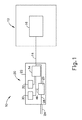
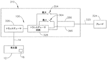
図1は、例示的な外科用システム(10)の構成要素を図形的ブロック形態で示したものである。示されるように、システム(10)は、超音波発生器(12)及び超音波外科用器具(20)を備える。以下でより詳細に記載されるように、器具(20)は、超音波振動エネルギーを使用して、実質的に同時に、組織(例えば、血管など)を切開し、組織を封着又は接合するように動作可能である。あくまで一例として、器具(20)は、米国特許第5,322,055号、米国特許第5,873,873号、米国特許第5,980,510号、米国特許第6,325,811号、米国特許第6,773,444号、米国特許第6,783,524号、米国特許第9,095,367号、米国特許公開第2006/0079874号、米国特許公開第2007/0191713号、米国特許公開第2007/0282333号、米国特許公開第2008/0200940号、米国特許公開第2009/0105750号、米国特許公開第2010/0069940号、米国特許公開第2011/0015660号、米国特許公開第2012/0112687号、米国特許公開第2012/0116265号、米国特許公開第2014/0005701号、米国特許公開第2015/0080924号、及び/又は米国特許出願第61/410,603号の教示のうちの少なくとも一部に従って構築され、動作可能であってもよい。前述の特許、公開、及び出願の各々の開示が参照により本明細書に組み込まれる。
I. Overview of an exemplary ultrasonic surgical system FIG. 1 shows the components of an exemplary surgical system (10) in graphical block form. As shown, the system (10) comprises an ultrasonic generator (12) and an ultrasonic surgical instrument (20). As described in more detail below, the instrument (20) uses ultrasonic vibrational energy to incise tissue (eg, blood vessels, etc.) at substantially the same time to seal or join the tissue. It is possible to operate. As an example, the appliance (20) includes U.S. Pat. No. 5,322,055, U.S. Pat. No. 5,873,873, U.S. Pat. No. 5,980,510, U.S. Pat. No. 6,325,811, U.S. Patent No. 6,773,444, U.S. Patent No. 6,783,524, U.S. Patent No. 9,095,367, U.S. Patent Publication No. 2006/0079874, U.S. Patent Publication No. 2007/0191713, U.S. Patent Publication No. 2007/0282333, US Patent Publication No. 2008/0200940, US Patent Publication No. 2009/0105750, US Patent Publication No. 2010/0069940, US Patent Publication No. 2011/0015660, US Patent Publication No. 2012/0112687 No., U.S. Patent Publication No. 2012/0116265, U.S. Patent Publication No. 2014/0005701, U.S. Patent Publication No. 2015/0080924, and / or at least part of the teachings of U.S. Patent Application No. 61 / 410,603. It may be constructed and operational according to. The disclosures of the patents, publications, and applications mentioned above are incorporated herein by reference.
また、器具(20)がHARMONIC ACE(登録商標)Ultrasonic Shears、HARMONIC WAVE(登録商標)Ultrasonic Shears、HARMONIC FOCUS(登録商標)Ultrasonic Shears、及び/又はHARMONIC SYNERGY(登録商標)Ultrasonic Bladesとの様々な構造的及び機能的な類似性を有し得ることを理解されたい。更に、器具(20)は、本明細書で引用され、参照により本明細書に組み込まれる他の参考文献のうちのいずれかにおいて教示される装置と、様々な構造的及び機能的な類似性を有し得る。本明細書に引用される参考文献の教示と、HARMONIC ACE(登録商標)Ultrasonic Shears、HARMONIC WAVE(登録商標)Ultrasonic Shears、HARMONIC FOCUS(登録商標)Ultrasonic Shears、及び/又はHARMONIC SYNERGY(登録商標)Ultrasonic Bladesの教示と、器具(20)に関する以下の教示との間に何らかの重複が存在する場合は、本明細書のいかなる記述も、認められた先行技術と見なす意図はない。本明細書のいくつかの教示は、事実、本明細書に引用した参考文献、並びにHARMONIC ACE(登録商標)Ultrasonic Shears、HARMONIC WAVE(登録商標)Ultrasonic Shears、HARMONIC FOCUS(登録商標)Ultrasonic Shears、及びHARMONIC SYNERGY(登録商標)Ultrasonic Bladesの教示の範囲を超えるであろう。 In addition, the instrument (20) is Harmonic ACE (registered trademark) Ultrasonic Shears, HARMONIC WAVE (registered trademark) Ultrasonic Shears, HARMONIC FOCUS (registered trademark) Ultrasonic Shears (registered trademark) Ultrasonic Ultras It should be understood that they can have physical and functional similarities. In addition, instrument (20) has various structural and functional similarities to the devices cited herein and taught in any of the other references incorporated herein by reference. Can have. The teachings of the references cited herein and the HARMONIC ACE® Ultrasonic Shears, HARMONIC WAVE® Ultrasonic Shears, HARMONIC FOCUS® Ultrasonic Shears®, and / or Harmonic Shears. If there is any overlap between the Brades teachings and the following teachings regarding the instrument (20), then no description herein is intended to be considered as recognized prior art. Some of the teachings herein are, in fact, the references cited herein, as well as the HARMONIC ACE® Ultrasonic Shears, HARMONIC WAVE® Ultrasonic Shears, HARMONIC FOCUS® Ultrasound It will be beyond the teachings of HARMONIC SYNERGY® Ultrasonic Blades.
発生器(12)及び器具(20)は、ケーブル(14)を介して一緒に連結される。ケーブル(14)は、複数の導線を備えてもよく、発生器(12)から器具(20)への一方向の電気的導通、及び/又は発生器(12)と器具(20)との間の双方向の電気的導通を与えることができる。あくまで一例として、発生器(12)は、Ethicon Endo−Surgery,Inc.(Cincinnati,Ohio)により販売されているGEN04、GEN11、又はGEN300を備えてもよい。加えて、又はあるいは、発生器(12)は、2011年4月14日公開の「Surgical Generator for Ultrasonic and Electrosurgical Devices」と題される米国公開第2011/0087212号の教示の少なくとも一部に従って構築され得、その開示は、参照により本明細書に組み込まれる。あるいは、任意の他の好適な発生器(12)が使用されてもよい。以下でより詳細に記載されるように、発生器(12)は、電力を器具(20)に供給して超音波外科手術を行うように動作可能である。ケーブル(14)が単に省略され得るように、システム(10)のいくつかの変形例が、発生器(12)を器具(20)内に組み込むことができることも理解されたい。 The generator (12) and the appliance (20) are connected together via a cable (14). The cable (14) may include a plurality of conductors, one-way electrical conduction from the generator (12) to the appliance (20), and / or between the generator (12) and the appliance (20). Bidirectional electrical continuity can be provided. As an example, the generator (12) is described by Ethicon Endo-Surgery, Inc. May include GEN04, GEN11, or GEN300 sold by (Cincinnati, Ohio). In addition, or / or, the generator (12) was constructed in accordance with at least part of the teachings of US Publication No. 2011/0087212, entitled "Surgical Generator for Ultrasonic and Electrical Devices," published April 14, 2011. Obtained, the disclosure thereof is incorporated herein by reference. Alternatively, any other suitable generator (12) may be used. As described in more detail below, the generator (12) can operate to power the instrument (20) to perform ultrasonic surgery. It should also be appreciated that some variants of the system (10) can incorporate the generator (12) into the appliance (20) so that the cable (14) may simply be omitted.
器具(20)は、ハンドルアセンブリ(22)を備え、ハンドルアセンブリ(22)は、外科手術中に操作者の片手(又は両手)に把持されて操作者の片手(又は両手)によって操作されるように構成されている。例えば、いくつかの変形例では、ハンドルアセンブリ(22)は、操作者によって鉛筆のように把持されてもよい。いくつかの他の変形例では、ハンドルアセンブリ(22)は、操作者によってハサミのように握られるハサミグリップを含んでいてもよい。いくつかの他の変形例では、ハンドルアセンブリ(22)は、操作者によってピストルのように握られるピストルグリップを含んでいてもよい。言うまでもなく、ハンドルアセンブリ(22)は、任意の他の好適な様態で握られるように構成されてもよい。更に、器具(20)のいくつかの変形例では、ハンドルアセンブリ(22)の代わりに、器具を(例えば、リモートコントロールなどを介して)動作させるように構成されたロボット手術システムに連結された本体を代用してもよい。 The instrument (20) comprises a handle assembly (22) such that the handle assembly (22) is gripped by one (or both) hands of the operator during surgery and operated by one (or both) hands of the operator. It is configured in. For example, in some variations, the handle assembly (22) may be gripped by the operator like a pencil. In some other variations, the handle assembly (22) may include scissors grips that are gripped like scissors by the operator. In some other variations, the handle assembly (22) may include a pistol grip that is gripped like a pistol by the operator. Needless to say, the handle assembly (22) may be configured to be gripped in any other suitable manner. Further, in some variants of the instrument (20), instead of the handle assembly (22), the body connected to a robotic surgery system configured to operate the instrument (eg, via remote control, etc.). May be substituted.
本例では、ブレード(24)は、ハンドルアセンブリ(22)から遠位に延在している。ハンドルアセンブリ(22)は、超音波トランスデューサ(26)及び超音波導波管(28)を含み、超音波導波管(28)は、超音波トランスデューサ(26)をブレード(24)と連結する。超音波トランスデューサ(26)は、ケーブル(14)を介して発生器(12)から電力を受け取る。超音波トランスデューサ(26)は、その圧電特性により、かかる電力を超音波振動エネルギーに変換するように動作可能である。 In this example, the blade (24) extends distally from the handle assembly (22). The handle assembly (22) includes an ultrasonic transducer (26) and an ultrasonic waveguide (28), which connects the ultrasonic transducer (26) to the blade (24). The ultrasonic transducer (26) receives power from the generator (12) via the cable (14). Due to its piezoelectric properties, the ultrasonic transducer (26) can operate to convert the applied electric power into ultrasonic vibration energy.
超音波導波管(28)は、可撓性、半可撓性、剛性のものであってもよいか、又は任意の他の好適な性質を有してもよい。上述のように、超音波トランスデューサ(26)は、超音波導波管(28)を介してブレード(24)と一体連結される。具体的には、超音波トランスデューサ(26)を超音波周波数で振動するように起動している場合、かかる振動は、超音波導波管(28)を介してブレード(24)に伝達されて、ブレード(24)も超音波周波数で振動することになる。ブレード(24)が起動状態である(すなわち、超音波的に振動している)場合、ブレード(24)は、組織を効果的に切断し、組織を封着するように動作可能である。したがって、超音波トランスデューサ(26)、超音波導波管(28)、及びブレード(24)は、発生器(12)によって電力供給される際に外科手術を行うための超音波エネルギーを供給する音響アセンブリを一緒に形成する。ハンドルアセンブリ(22)は、操作者を、トランスデューサ(26)、超音波導波管(28)、及びブレード(24)によって形成される音響アセンブリの振動から実質的に隔離するように構成されている。 The ultrasonic waveguide (28) may be flexible, semi-flexible, rigid, or may have any other suitable property. As described above, the ultrasonic transducer (26) is integrally connected to the blade (24) via the ultrasonic waveguide (28). Specifically, when the ultrasonic transducer (26) is activated to vibrate at an ultrasonic frequency, the vibration is transmitted to the blade (24) via the ultrasonic waveguide (28). The blade (24) will also oscillate at the ultrasonic frequency. When the blade (24) is in the activated state (ie, ultrasonically vibrating), the blade (24) can behave to effectively cut the tissue and seal the tissue. Thus, the ultrasonic transducer (26), ultrasonic waveguide (28), and blade (24) provide acoustic energy to perform surgery when powered by the generator (12). Form the assembly together. The handle assembly (22) is configured to substantially isolate the operator from the vibrations of the acoustic assembly formed by the transducer (26), ultrasonic waveguide (28), and blade (24). ..
いくつかの変形例では、超音波導波管(28)は、超音波導波管(28)を介してブレード(24)に伝達される機械的振動を増幅してもよい。超音波導波管(28)は、超音波導波管(28)に沿った長手方向振動の利得を制御するための特徴部、及び/又は超音波導波管(28)をシステム(10)の共振周波数と同調させるための特徴部を更に有してもよい。例えば、超音波導波管(28)は、ほぼ均一な断面などの任意の好適な断面寸法/構成を有してもよく、様々な部分で先細りになっていてもよく、その全長に沿って先細りになっていてもよく、又は任意の他の好適な構成を有してもよい。超音波導波管(28)は、例えば、システムの波長の1/2の整数倍にほぼ等しい長さ(nλ/2)を有してもよい。超音波導波管(28)及びブレード(24)は、チタン合金(すなわち、Ti−6Al−4V)、アルミニウム合金、サファイア、ステンレス鋼、又は任意の他の音響的に適合した材料若しくは材料の組み合わせなどの超音波エネルギーを効率的に伝搬する材料又は材料の組み合わせから構築された中実コアシャフトから製作されてもよい。 In some variations, the ultrasonic waveguide (28) may amplify the mechanical vibration transmitted to the blade (24) via the ultrasonic waveguide (28). The ultrasonic waveguide (28) includes a feature portion for controlling the gain of longitudinal vibration along the ultrasonic waveguide (28) and / or the ultrasonic waveguide (28) in the system (10). It may further have a feature portion for tuning with the resonance frequency of. For example, the ultrasonic waveguide (28) may have any suitable cross-sectional dimensions / configuration, such as a nearly uniform cross-section, or may be tapered at various parts along its overall length. It may be tapered or may have any other suitable configuration. The ultrasonic waveguide (28) may have, for example, a length (nλ / 2) approximately equal to an integral multiple of 1/2 the wavelength of the system. The ultrasonic waveguide (28) and blade (24) are made of titanium alloy (ie, Ti-6Al-4V), aluminum alloy, sapphire, stainless steel, or any other acoustically compatible material or combination of materials. It may be made from a solid core shaft constructed from a material or a combination of materials that efficiently propagates ultrasonic energy such as.
本例では、ブレード(24)の遠位端は、組織による負荷が音響アセンブリに加えられていないとき、好ましい共振周波数foに音響アセンブリを同調させるために、導波管(28)を介して伝達される共振超音波振動に関連付けられるアンチノードに対応する位置に(すなわち、音響アンチノードに)位置する。トランスデューサ(26)が通電されると、ブレード(24)の遠位端は、例えば、ピーク間で約10〜500マイクロメートル、場合によっては、例えば、55.5kHzの所定の振動周波数foにて約20〜約200マイクロメートルの範囲で長手方向に移動するように構成されている。本例のトランスデューサ(26)が起動しているとき、これらの機械的な振動は、ブレード(24)に到達するように導波管(28)を介して伝達され、それにより共振超音波周波数でブレード(24)の振動をもたらす。このため、ブレード(24)の超音波振動が、組織の切断と隣接した組織細胞内のタンパク質の変性とを同時に行い、それにより比較的少ない熱拡散で凝固効果を提供することができる。いくつかの変形例では、また、組織を焼灼するために電流がブレード(24)を介して提供されてもよい。 In this embodiment, the distal end of the blade (24), when the load by the tissue is not applied to the acoustic assembly, in order to tune the acoustic assembly to a preferred resonant frequency f o, via a waveguide (28) It is located at the position corresponding to the antinode associated with the transmitted resonant ultrasonic vibration (ie, at the acoustic antinode). When the transducer (26) is energized, the distal end of the blade (24), for example, about 10 to 500 microns peak-to-peak, in some cases, for example, at a predetermined vibration frequency f o of 55.5kHz It is configured to move longitudinally in the range of about 20 to about 200 micrometers. When the transducer (26) of this example is activated, these mechanical vibrations are transmitted through the waveguide (28) to reach the blade (24), thereby at resonant ultrasonic frequencies. It causes vibration of the blade (24). Therefore, the ultrasonic vibration of the blade (24) simultaneously cuts the tissue and denatures the protein in the adjacent tissue cells, whereby the coagulation effect can be provided with relatively little heat diffusion. In some variations, an electric current may also be provided through the blade (24) to cauterize the tissue.
あくまで一例として、超音波導波管(28)及びブレード(24)は、Ethicon Endo−Surgery,Inc.(Cincinnati,Ohio)により製品コードSNGHK及びSNGCBとして販売されている構成要素を備えてもよい。あくまで更なる一例として、超音波導波管(28)及び/又はブレード(24)は、開示内容が参照により本明細書に組み込まれる、2002年7月23日発行の米国特許第6,423,082号、表題「Ultrasonic Surgical Blade with Improved Cutting and Coagulation Features」の教示に従って構築されてもよく、動作可能であり得る。別の単なる例証的な例として、超音波導波管(28)及び/又はブレード(24)は、開示内容が参照により本明細書に組み込まれる、1994年6月28日発行の米国特許第5,324,299号、表題「Ultrasonic Scalpel Blade and Methods of Application」の教示に従って構築されて、動作可能であり得る。超音波導波管(28)及びブレード(24)の他の好適な特性及び形態が、本明細書の教示を考慮することにより当業者に明らかになるであろう。 As an example, the ultrasonic waveguide (28) and the blade (24) are described in Ethicon Endo-Surgery, Inc. (Cincinnati, Ohio) may include components sold as product codes SNGHK and SNGCB. As a further example, ultrasonic waveguides (28) and / or blades (24) are provided in US Pat. No. 6,423, issued July 23, 2002, the disclosure of which is incorporated herein by reference. It may be constructed and operational according to the teachings of No. 082, entitled "Ultrasonic Surgical Blade with Implemented Cutting and Coamination Features". As another mere exemplary example, ultrasonic waveguides (28) and / or blades (24) are described in US Pat. No. 5, issued June 28, 1994, the disclosure of which is incorporated herein by reference. , 324,299, title "Ultrasonic Scalpel Blade and Methods of Application", can be constructed and operational according to the teachings. Other suitable properties and forms of the ultrasonic waveguide (28) and blade (24) will be apparent to those skilled in the art by considering the teachings herein.
本例のハンドルアセンブリ(22)はまた、制御セレクタ(30)及び起動スイッチ(32)を含み、これらは各々、回路基板(34)と通信する。あくまで一例として、回路基板(34)は、従来の回路基板、フレックス回路、リジッドフレックス回路を備えてもよく、又は任意の他の好適な形態を有してもよい。制御セレクタ(30)及び起動スイッチ(32)は、1つ若しくは2つ以上の導線を介して、回路基板若しくはフレックス回路に形成された配線を介して、かつ/又は任意の他の好適な方法で、回路基板(34)と通信することができる。回路基板(34)は、ケーブル(14)と連結され、ケーブル(14)は、次いで、発生器(12)内の制御回路(16)と連結される。起動スイッチ(32)は、超音波トランスデューサ(26)への電源を選択的に起動させるように動作可能である。特に、スイッチ(32)が起動すると、かかる起動によってケーブル(14)を介して超音波トランスデューサ(26)に適切な電力が伝達される。あくまで一例として、起動スイッチ(32)は、本明細書で引用される様々な参照文献の教示のうちのいずれかに従って構築されてもよい。起動スイッチ(32)がとり得る他の様々な形態は、本明細書の教示を考慮することにより当業者に明らかになるであろう。 The handle assembly (22) of this example also includes a control selector (30) and a start switch (32), each communicating with a circuit board (34). As an example, the circuit board (34) may include a conventional circuit board, a flex circuit, a rigid flex circuit, or may have any other suitable form. The control selector (30) and start switch (32) are via one or more conductors, via wiring formed on the circuit board or flex circuit, and / or by any other suitable method. , Can communicate with the circuit board (34). The circuit board (34) is connected to the cable (14), which is then connected to the control circuit (16) in the generator (12). The activation switch (32) can operate to selectively activate the power supply to the ultrasonic transducer (26). In particular, when the switch (32) is activated, such activation transfers appropriate power to the ultrasonic transducer (26) via the cable (14). As an example only, the activation switch (32) may be constructed according to any of the teachings of the various references cited herein. Various other forms that the activation switch (32) can take will be apparent to those skilled in the art by considering the teachings herein.
本例では、外科用システム(10)は、少なくとも2つの異なるレベル又は種類の超音波エネルギー(例えば、異なる周波数及び/又は振幅など)をブレード(24)において供給するように動作可能である。そのために、制御セレクタ(30)は、操作者が所望のレベル/振幅の超音波エネルギーを選択することができるように動作可能である。あくまで一例として、制御セレクタ(30)は、本明細書で引用される様々な参照文献の教示のうちのいずれかに従って構築されてもよい。制御セレクタ(30)がとり得る他の様々な形態は、本明細書の教示を考慮することにより当業者に明らかになるであろう。いくつかの変形例では、操作者が制御セレクタ(30)によって選択を行う場合、操作者の選択は、ケーブル(14)を介して発生器(12)の制御回路(16)に戻して伝達され、これに従って、次回操作者が起動スイッチ(32)を作動させるときに、制御回路(16)が発生器(12)から伝達される電力を調節する。 In this example, the surgical system (10) can operate to deliver at least two different levels or types of ultrasonic energy (eg, different frequencies and / or amplitudes, etc.) at the blade (24). To that end, the control selector (30) is operable so that the operator can select the ultrasonic energy of the desired level / amplitude. As an example only, the control selector (30) may be constructed according to any of the teachings of the various references cited herein. Various other forms that the control selector (30) can take will become apparent to those skilled in the art by considering the teachings herein. In some variants, when the operator makes a selection with the control selector (30), the operator's selection is transmitted back to the control circuit (16) of the generator (12) via the cable (14). According to this, the next time the operator activates the start switch (32), the control circuit (16) adjusts the power transmitted from the generator (12).
ブレード(24)において供給される超音波エネルギーのレベル/振幅は、発生器(12)からケーブル(14)を介して器具(20)に伝達される電力の特性の関数であり得ることを理解されたい。したがって、発生器(12)の制御回路(16)は、制御セレクタ(30)を通じて選択された超音波エネルギーのレベル/振幅又は種類に関連付けられる特性を有する電力を(ケーブル(14)を介して)供給することができる。したがって、発生器(12)は、制御セレクタ(30)を介して操作者によって行われる選択に基づいて異なる種類又は程度の電力を超音波トランスデューサ(26)に伝達するように動作可能であり得る。具体的には、かつあくまで一例として、発生器(12)は、印加される信号の電圧及び/又は電流を増大させて、音響アセンブリの長手方向振幅を増大させることができる。単なる例証的な一例として、発生器(12)は、それぞれ、約50マイクロメートル及び約90マイクロメートルの振動共振振幅に対応し得る「レベル1」と「レベル5」との間の選択可能性を提供することができる。制御回路(16)が構成され得る様々な方法が本明細書の教示を考慮することにより当業者に明らかになるであろう。制御セレクタ(30)及び起動スイッチ(32)の代わりに、2つ又は3つ以上の起動スイッチ(32)が使用され得ることも理解されたい。いくつかのかかる変形例では、ある起動スイッチ(32)は、ある電力レベル/種類でブレード(24)を起動させるように動作可能である一方で、別の起動スイッチ(32)は、別の電力レベル/種類などでブレード(24)を起動させるように動作可能である。 It is understood that the level / amplitude of ultrasonic energy delivered at the blade (24) can be a function of the characteristics of the power transmitted from the generator (12) to the appliance (20) via the cable (14). I want to. Therefore, the control circuit (16) of the generator (12) delivers power (via cable (14)) with properties associated with the level / amplitude or type of ultrasonic energy selected through the control selector (30). Can be supplied. Thus, the generator (12) may be operational to transfer different types or degrees of power to the ultrasonic transducer (26) based on the choices made by the operator via the control selector (30). Specifically, and only as an example, the generator (12) can increase the voltage and / or current of the applied signal to increase the longitudinal amplitude of the acoustic assembly. As a mere exemplary example, the generator (12) offers a choice between "level 1" and "level 5" that can accommodate vibration resonance amplitudes of about 50 micrometers and about 90 micrometers, respectively. Can be provided. Various methods by which the control circuit (16) can be constructed will be apparent to those skilled in the art by considering the teachings herein. It should also be understood that two or more activation switches (32) may be used instead of the control selector (30) and activation switch (32). In some such variants, one start switch (32) can operate to activate the blade (24) at one power level / type, while another start switch (32) has another power. It is possible to operate so as to activate the blade (24) depending on the level / type and the like.
いくつかの代替の変形例では、制御回路(16)は、ハンドルアセンブリ(22)内に位置する。例えば、いくつかのこのような変形例では、発生器(12)は、単に1つのタイプの電力(例えば、利用可能な単に1つの電圧及び/又は電流)をハンドルアセンブリ(22)に伝達し、ハンドルアセンブリ(22)内の制御回路(16)は、電力が超音波トランスデューサ(26)に達する前に、制御セレクタ(30)を介して操作者が行った選択に従って、電力(例えば、電力の電圧)を変更するように動作可能である。更に、発生器(12)を外科用システム(10)の全ての他のコンポーネントと一緒にハンドルアセンブリ(22)内に組み込んでもよい。例えば、1つ若しくは2つ以上の電池(図示せず)又は他の携帯型電力源をハンドルアセンブリ(22)内に設けてもよい。図1に示される構成要素が再配置されるか、又は他の方法で構成若しくは修正され得る更なる他の好適な方法が、本明細書の教示を考慮することにより当業者に明らかになるであろう。 In some alternative variants, the control circuit (16) is located within the handle assembly (22). For example, in some such variants, the generator (12) simply transfers one type of power (eg, just one voltage and / or current available) to the handle assembly (22). The control circuit (16) in the handle assembly (22) follows the choice made by the operator through the control selector (30) before the power reaches the ultrasonic transducer (26), according to the power (eg, voltage of power). ) Can be changed. In addition, the generator (12) may be incorporated into the handle assembly (22) along with all other components of the surgical system (10). For example, one or more batteries (not shown) or other portable power source may be provided within the handle assembly (22). Further other suitable methods in which the components shown in FIG. 1 can be rearranged or otherwise configured or modified will become apparent to those skilled in the art by considering the teachings herein. There will be.
II.例示的な超音波外科用器具の概要
以下の考察は、器具(20)の様々な例示的な構成要素及び構成に関するものである。以下に記載される器具(20)の様々な実施例を、上述の外科用システム(10)に容易に組み込むことができることを理解されたい。また、上述の器具(20)の様々な構成要素及び動作性を以下に記載の器具(20)の例示的な変形例に容易に組み込むことができることも理解されたい。上記及び下記の教示を組み合わせ得る様々な好適な方法が、本明細書の教示を考慮することにより当業者に明らかになるであろう。また、下記の教示が、本明細書で引用される参考文献の様々な教示と容易に組み合わせられ得ることも理解されたい。
II. Outline of the exemplary ultrasonic surgical instrument The following discussion relates to various exemplary components and configurations of the instrument (20). It should be understood that various embodiments of the instruments (20) described below can be easily incorporated into the surgical system (10) described above. It should also be appreciated that the various components and operability of the device (20) described above can be easily incorporated into the exemplary variants of the device (20) described below. Various suitable methods that can combine the above and the following teachings will become apparent to those skilled in the art by considering the teachings herein. It should also be appreciated that the following teachings can be easily combined with the various teachings of the references cited herein.
A.例示的な超音波外科用メス及び掻爬取器具
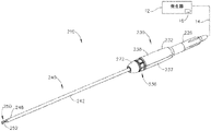
図2は、上述のシステム(10)の器具(20))として使用され得る例示的な超音波外科用器具(110)を示す。したがって、器具(110)の少なくとも一部は、器具(20)に関する上述の教示のうちの少なくとも一部に従って、構築及び動作されてもよい。器具(20)と同様に、器具(110)は、実質的に同時に、組織を切開し、組織(例えば、血管など)を封着又は接合するように動作可能である。この例の器具(110)は、メスとして、かつ/又掻爬取器具として使用されるように構成されている。
A. Illustrative Ultrasonic Scalpel and Curettage Instrument FIG. 2 shows an exemplary ultrasonic surgical instrument (110) that can be used as the instrument (20)) of the system (10) described above. Thus, at least a portion of the instrument (110) may be constructed and operated in accordance with at least some of the above teachings relating to the instrument (20). Like the instrument (20), the instrument (110) can operate at substantially the same time to incise the tissue and seal or join the tissue (eg, blood vessels, etc.). The instrument (110) of this example is configured to be used as a scalpel and / also as a curettage instrument.
図2に示されるように、器具(110)は、トランスデューサアセンブリ(100)、音響導波管(120)、及び囲い板(130)を備える。導波管(120)の遠位端は、超音波ブレード(124)を含む。本例の超音波ブレード(124)は、スコップ状の形状を有する。超音波ブレード(124)は、湾曲したブレード(例えば、Ethicon Endo−Surgery,Inc.製品コードSNGCB)、フックブレード(例えば、Ethicon Endo−Surgery,Inc.製品コードSNGHK)、組み合わせフックブレード(例えば、Ethicon Endo−Surgery,Inc.製品コードSNGHK2)を備えてもよいことを理解されたい。なお別の単なる例証的な例として、ブレード(24)は、その開示が参照により本明細書に組み込まれる、2014年6月12日発行の「Ultrasonic Surgical Blade」と題された米国公開第2014/0163595号、及び/又はその開示が参照により本明細書に組み込まれる、2011年11月15発行の「Ultrasonic Surgical Instrument Blades」と題された米国特許第8,057,498号の教示の少なくとも一部に従って構築され得る。ブレード(124)に使用され得る他の好適な構成は、本明細書の教示を考慮することにより当業者には明らかになるであろう。 As shown in FIG. 2, the instrument (110) comprises a transducer assembly (100), an acoustic waveguide (120), and an enclosure (130). The distal end of the waveguide (120) includes an ultrasonic blade (124). The ultrasonic blade (124) of this example has a scoop-like shape. The ultrasonic blade (124) includes a curved blade (for example, Ethicon Endo-Surgery, Inc. product code SNGCB), a hook blade (for example, Ethicon Endo-Surgery, Inc. product code SNGHK), and a combination hook blade (for example, Ethicon). It should be understood that Endo-Surgery, Inc. product code SNGHK2) may be provided. Yet another mere exemplary example is Blade (24), published in June 12, 2014, entitled "Ultrasonic Surgical Blade," whose disclosure is incorporated herein by reference. At least part of the teaching of US Pat. No. 8,057,498, entitled "Ultrasonic Surgical Instrument Blades," published November 15, 2011, which is incorporated herein by reference at 0163595 and / or its disclosure. Can be constructed according to. Other suitable configurations that may be used for the blade (124) will become apparent to those skilled in the art by considering the teachings herein.
以下でより詳細に記載されるように、導波管(120)は、超音波振動をトランスデューサアセンブリ(100)から超音波ブレード(124)に伝達し、それによって組織を切断及び/又は封着するように構成される。囲い板(130)の近位端は、トランスデューサアセンブリ(100)の遠位端とねじ込み連結する。囲い板(130)は、囲い板(130)を近位端から遠位端まで完全に貫通する内部ボア(132)を画定することによって、近位開口部及び遠位開口部を画定する。導波管(120)は、導波管(120)が囲い板(130)の近位開口部を介してトランスデューサアセンブリ(100)とねじ込み連結され得るように、囲い板(130)の内部ボア(132)内に配設される。超音波ブレード(124)を含む導波管(120)の遠位部分は、囲い板(130)の遠位開口部を介して囲い板(130)の遠位端から遠位方向に突出する。 As described in more detail below, the waveguide (120) transmits ultrasonic vibrations from the transducer assembly (100) to the ultrasonic blade (124), thereby cutting and / or sealing the tissue. It is configured as follows. The proximal end of the enclosure (130) is screwed into connection with the distal end of the transducer assembly (100). The enclosure (130) defines the proximal and distal openings by defining an internal bore (132) that completely penetrates the enclosure (130) from the proximal end to the distal end. The waveguide (120) has an internal bore of the enclosure (130) so that the waveguide (120) can be screwed into the transducer assembly (100) through the proximal opening of the enclosure (130). 132) is arranged in. The distal portion of the waveguide (120), including the ultrasonic blade (124), projects distally from the distal end of the enclosure (130) through the distal opening of the enclosure (130).
本例のトランスデューサアセンブリ100は、ケーブル(14)を介して発生器(12)に連結されるが、トランスデューサアセンブリ(100)の代わりにコードレストランスデューサであってもよいことを理解されたい。トランスデューサアセンブリ(100)は、その開示が参照により本明細書に組み込まれる、2015年5月28日発行の「Methods and Features for Coupling Ultrasonic Surgical Instrument Components Together」と題された米国特許公開第2015/0148829号の教示に従って構成され得る。本例では、トランスデューサアセンブリ(100)は、トランスデューサハウジング(112)内に圧電スタック(図示せず)を含む。本例のトランスデューサアセンブリ(100)を起動させると、圧電スタック中で電界が生じ、圧電スタック及びホーン(図示せず)がハウジング(112)内でそれに対して振動する。装着フランジ(図示せず)は、トランスデューサアセンブリ(100)のホーン(図示せず)をハウジング(112)に連結し、それにより圧電スタックをハウジング(112)内で構造的に支持するために使用される。装着フランジは、圧電スタックからホーンに伝達される共振超音波振動と関連付けられたノードに位置し得る。トランスデューサアセンブリ(100)は、超音波周波数(例えば、55.5kHz)で機械的エネルギー又は振動を生み出すように動作可能である。トランスデューサアセンブリ(100)がホーンを介して導波管(120)に連結される場合、これらの機械的振動は、導波管(120)を通して超音波ブレード(124)に伝達される。
It should be understood that the
上述のトランスデューサ(26)と同様に、トランスデューサアセンブリ(100)は、ケーブル(14)を介して発生器(12)と連結される。トランスデューサアセンブリ(100)は、発生器(12)から電力を受け取り、上述のようにその電力を超音波振動に変換する。発生器(12)は、電源と、トランスデューサアセンブリ(100)を介した超音波振動の生成に特に適した電力プロファイルをトランスデューサアセンブリ(100)に供給するように構成された制御モジュールとを含み得る。あくまで一例として、発電機(12)は、Ethicon Endo−Surgery,Inc.(Cincinnati,Ohio)により販売されているGEN 300を含み得る。加えて、又はあるいは、発生器(12)は、2011年4月14日公開の「Surgical Generator for Ultrasonic and Electrosurgical Devices」と題される米国公開第2011/0087212号の教示の少なくとも一部に従って構築され得、その開示は、参照により本明細書に組み込まれる。また、発生器(12)の機能の少なくとも一部は器具(110)に統合されてもよく、器具(110)は更には電池又は他の内蔵電源を含んで、ケーブル(14)が省略されてもよいことを理解されたい。発生器(12)がとり得るなお他の好適な形態、並びに発生器(12)が提供し得る種々の特徴及び動作性は、本明細書の教示を考慮することにより当業者に明らかになるであろう。 Similar to the transducer (26) described above, the transducer assembly (100) is connected to the generator (12) via a cable (14). The transducer assembly (100) receives power from the generator (12) and converts that power into ultrasonic vibrations as described above. The generator (12) may include a power source and a control module configured to supply the transducer assembly (100) with a power profile that is particularly suitable for generating ultrasonic vibrations through the transducer assembly (100). As an example, the generator (12) is described by Ethicon Endo-Surgery, Inc. GEN 300 sold by (Cincinnati, Ohio) may be included. In addition, or / or, the generator (12) was constructed in accordance with at least part of the teachings of US Publication No. 2011/0087212, entitled "Surgical Generator for Ultrasonic and Electrical Devices," published April 14, 2011. Obtained, the disclosure thereof is incorporated herein by reference. Also, at least some of the functionality of the generator (12) may be integrated into the appliance (110), which further includes a battery or other built-in power supply, omitting the cable (14). Please understand that it is also good. Still other suitable forms that the generator (12) can take, as well as the various features and operability that the generator (12) can provide, will become apparent to those skilled in the art by considering the teachings herein. There will be.
トランスデューサアセンブリ(100)によって生成された超音波振動は、囲い板(130)を通って延び超音波ブレード(124)に達する、音響導波管(120)に沿って伝達される。上述のように、超音波ブレード(124)が起動状態(すなわち、超音波振動している)にあるとき、超音波ブレード(124)は、組織を効率的に切開及び封着するように動作可能である。導波管(120)が、導波管(120)を通って伝達される機械的振動を増幅するように構成され得ることを理解されたい。更に、導波管(120)は、導波管(120)に沿った長手方向の振動のゲインを制御するように動作可能な特徴部、及び/又は導波管(210)を系の共振周波数に同調させる特徴部を含み得る。 The ultrasonic vibrations generated by the transducer assembly (100) are transmitted along an acoustic waveguide (120) that extends through the enclosure (130) and reaches the ultrasonic blades (124). As mentioned above, when the ultrasonic blade (124) is in the activated state (ie, ultrasonically vibrating), the ultrasonic blade (124) can operate to efficiently incis and seal the tissue. Is. It should be understood that the waveguide (120) may be configured to amplify the mechanical vibrations transmitted through the waveguide (120). Further, the waveguide (120) has a feature portion that can operate to control the gain of vibration in the longitudinal direction along the waveguide (120), and / or the resonant frequency of the waveguide (210). It may include a feature that is tuned to.
本例では、導波管(120)に連結された超音波ブレード(124)は、超音波周波数で振動する。本例では、組織による負荷が音響アセンブリに加えられていないときに、音響アセンブリを好ましい共振周波数foに同調させるために、超音波ブレード(124)の遠位端は、導波管(120)を通して伝達される共振超音波振動と関連付けられたアンチノードに対応する位置に位置付けられている。トランスデューサアセンブリ(100)が通電されると、超音波ブレード(124)の遠位端は、例えば、ピーク間で約10〜500マイクロメートル、場合によっては、例えば、55,500Hzの所定の振動周波数foにて約20〜約200マイクロメートルの範囲で長手方向に移動するように構成されている。 In this example, the ultrasonic blade (124) connected to the waveguide (120) vibrates at the ultrasonic frequency. In this example, when the load by the tissue is not applied to the acoustic assembly, in order to tune the acoustic assembly to a preferred resonant frequency f o, the distal end of the ultrasonic blade (124), the waveguide (120) It is located in a position corresponding to the antinode associated with the resonant ultrasonic vibration transmitted through. When the transducer assembly (100) is energized, the distal end of the ultrasonic blade (124) will have a predetermined vibration frequency f, eg, about 10 to 500 micrometers between peaks, and in some cases 55,500 Hz. It is configured to move in the longitudinal direction in the range of about 20 to about 200 micrometers at o.
本例のトランスデューサアセンブリ(100)が起動すると、得られた機械的振動は、導波管(120)を介して伝達されて超音波ブレード(124)に達し、それにより共振超音波振動での超音波ブレード(124)の振動が提供される。このようにして、組織に超音波ブレード(124)が接触すると、超音波ブレード(124)の超音波振動は、組織を切断すると同時に、隣接する組織細胞中のタンパク質を変性させ、それにより比較的少量の熱分散を伴う凝固効果が提供され得る。いくつかの変形例では、組織を更に封着するために、超音波ブレード(124)を通して電流(例えば、RF範囲内)も供給され得る。例えば、単極又は双極RFエネルギーが、超音波ブレード(124)を通して供給され得る。 When the transducer assembly (100) of this example is activated, the resulting mechanical vibration is transmitted through the waveguide (120) to reach the ultrasonic blade (124), thereby superimposing in resonant ultrasonic vibration. Vibration of the ultrasonic blade (124) is provided. In this way, when the ultrasonic blade (124) comes into contact with the tissue, the ultrasonic vibration of the ultrasonic blade (124) cuts the tissue and at the same time denatures the proteins in the adjacent tissue cells, thereby relatively A coagulation effect with a small amount of thermal dispersion can be provided. In some variations, an electric current (eg, within the RF range) may also be supplied through the ultrasonic blade (124) to further seal the tissue. For example, unipolar or bipolar RF energy can be supplied through an ultrasonic blade (124).
器具(110)の前述の構成要素及び動作性は、単に例証である。器具(110)は、本明細書の教示を考慮することにより当業者に明らかになるであろう様々な他の方法で構成することができる。あくまで一例として、器具(110)の少なくとも一部は、その開示内容の全てが参照により本明細書に組み込まれる次の特許文献のいずれかの教示の少なくとも一部に従って構築及び動作可能されてもよい:米国特許第5,322,055号、米国特許第5,873,873号、米国特許第5,980,510号、米国特許第6,325,811号、米国特許第6,783,524号、米国特許第9,095,367号、米国特許公開第2006/0079874号、米国特許公開第2007/0191713号、米国特許公開第2007/0282333号、米国特許公開第2008/0200940号、米国特許公開第2010/0069940号、米国特許公開第2011/0015660号、米国特許公開第2012/0112687号、米国特許公開第2012/0116265、及び/又は米国特許公開第2014/0005701号。器具(110)の追加の単なる例証的な変形形態を以下でより詳細に説明する。以下に説明する変形形態は、とりわけ、上述した器具(110)及び本明細書に引用される参考文献のいずれかに言及される器具のいずれかに容易に適用され得ることを理解されたい。 The aforementioned components and operability of the instrument (110) are merely exemplary. The device (110) can be configured in various other ways that will be apparent to those skilled in the art by considering the teachings herein. As an example, at least a portion of the appliance (110) may be constructed and operational in accordance with at least a portion of the teachings of any of the following patent documents, all of which are disclosed herein by reference. : US Pat. No. 5,322,055, US Pat. No. 5,873,873, US Pat. No. 5,980,510, US Pat. No. 6,325,811, US Pat. No. 6,783,524. , U.S. Patent Publication Nos. 9,095,367, U.S. Patent Publication No. 2006/0079874, U.S. Patent Publication No. 2007/01/91713, U.S. Patent Publication No. 2007/0282333, U.S. Patent Publication No. 2008/0200940, U.S. Patent Publication 2010/0069940, US Patent Publication No. 2011/0015660, US Patent Publication No. 2012/0112687, US Patent Publication No. 2012/0116265, and / or US Patent Publication No. 2014/0005701. An additional mere exemplary variant of the instrument (110) is described in more detail below. It should be appreciated that the variants described below can be readily applied, among other things, to any of the instruments mentioned above (110) and any of the references cited herein.
B.環状アレイの起動ボタンを有する例示的な超音波外科用器具
図3は、上述のシステム(10)の器具(20)として使用され得る別の例示的な超音波外科用器具(210)を示す。したがって、器具(210)の少なくとも一部は、器具(20)に関する上述の教示のうちの少なくとも一部に従って構築及び動作されてもよい。器具(20)と同様に、器具(210)は、実質的に同時に、組織を切開し、組織(例えば、血管など)を封着又は接合するように動作可能である。この例の器具(210)は、メスとして使用されるように構成される。以下でより詳細に記載されるように、器具(210)は、起動特徴部への改良されたアクセスを提供する。
B. An exemplary ultrasonic surgical instrument with an annular array activation button FIG. 3 shows another exemplary ultrasonic surgical instrument (210) that can be used as an instrument (20) in the system (10) described above. Thus, at least a portion of the instrument (210) may be constructed and operated in accordance with at least some of the above teachings relating to the instrument (20). Like the instrument (20), the instrument (210) can operate at substantially the same time to make an incision in the tissue and seal or join the tissue (eg, blood vessel, etc.). The instrument (210) in this example is configured to be used as a scalpel. As described in more detail below, the instrument (210) provides improved access to the activation feature.
図3に示されるように、器具(210)は、ハンドルアセンブリ(230)、シャフトアセンブリ(240)、及びエンドエフェクタ(250)を備える。器具(210)の近位端は、超音波トランスデューサ(226)のハンドルアセンブリ(230)への挿入により、超音波トランスデューサ(226)を受容し、それを装着される。ハンドルアセンブリ(230)は、超音波トランスデューサ(226)が、シャフトアセンブリ(240)内でねじ込み接続によって導波管(248)に連結され得るように、超音波トランスデューサ(226)を受容するように構成されるが、任意の他の好適な種類の連結を使用してもよい。図2〜3示されるように、器具(210)は、超音波トランスデューサ(226)と連結して、単一ユニットを形成してもよい。 As shown in FIG. 3, the appliance (210) comprises a handle assembly (230), a shaft assembly (240), and an end effector (250). The proximal end of the instrument (210) receives and mounts the ultrasonic transducer (226) by inserting the ultrasonic transducer (226) into the handle assembly (230). The handle assembly (230) is configured to receive the ultrasonic transducer (226) so that the ultrasonic transducer (226) can be connected to the waveguide (248) by a screw connection within the shaft assembly (240). However, any other suitable type of coupling may be used. As shown in FIGS. 2-3, the instrument (210) may be coupled with an ultrasonic transducer (226) to form a single unit.
シャフトアセンブリ(240)は、外側シース(242)及び外側シース(242)内に配設された導波管(248)を含む。いくつかの変形例では、外側シース(242)及び導波管(248)は、器具(210)が低侵襲外科手術において使用され得るように、トロカール又は他の低侵襲性アクセスポートを通って嵌合するように寸法決めされる。導波管(248)は、導波管(28)に関して上述したものと類似の様式で、トランスデューサ(226)から超音波ブレード(252)に超音波振動を伝達するように構成されている。導波管(248)は、可撓性、半可撓性、又は剛性であってもよい。導波管(248)は、導波管(248)を介してブレード(252)に伝達される機械的振動を増幅するようにも構成されてもよい。導波管(248)は、導波管(248)の長手方向軸に対して実質的に垂直に、それを通って延在する少なくとも1つのボア(図示せず)を更に含み得る。ボアは、導波管(248)に沿って伝達される超音波振動と関連付けられたノードに対応する長手方向位置に位置してもよい。ボアは、導波管(248)を外側シース(242)に接続するコネクタピン(図示せず)を受容するように構成され得る。コネクタピンはノード位置に位置することになるため、ピンは、導波管(248)から外側シース(242)に超音波振動を伝達しないが、コネクタピンは依然として、外側シース(242)の長手方向及び回転の基底を提供し得る。 The shaft assembly (240) includes an outer sheath (242) and a waveguide (248) disposed within the outer sheath (242). In some variants, the outer sheath (242) and waveguide (248) fit through a trocar or other minimally invasive access port so that the instrument (210) can be used in minimally invasive surgery. It is sized to fit. The waveguide (248) is configured to transmit ultrasonic vibrations from the transducer (226) to the ultrasonic blade (252) in a manner similar to that described above for the waveguide (28). The waveguide (248) may be flexible, semi-flexible, or rigid. The waveguide (248) may also be configured to amplify the mechanical vibrations transmitted to the blades (252) via the waveguide (248). The waveguide (248) may further include at least one bore (not shown) extending substantially perpendicular to the longitudinal axis of the waveguide (248) and extending through it. The bore may be located in the longitudinal position corresponding to the node associated with the ultrasonic vibration transmitted along the waveguide (248). The bore may be configured to accept connector pins (not shown) that connect the waveguide (248) to the outer sheath (242). Since the connector pin will be located at the node position, the pin does not transmit ultrasonic vibrations from the waveguide (248) to the outer sheath (242), but the connector pin is still in the longitudinal direction of the outer sheath (242). And can provide the basis of rotation.
ブレード(252)は、超音波導波管(248)と統合されて、単一ユニットとして形成されてもよい。いくつかの変形例では、ブレード(252)は、ねじ込み接続、溶接継手、及び/又はいくつかの他の連結特徴部(複数可)によって導波管(248)に接続され得る。ブレード(252)の遠位端は、組織による負荷が音響アセンブリに加えられていないときに音響アセンブリを好ましい共振周波数foに同調させるために、導波管(248)及びブレード(252)に沿って伝達される超音波振動と関連付けられたアンチノードに対応する長手方向位置に、又はその近くに配設される。トランスデューサ(226)が通電されると、ブレード(252)の遠位端は、例えば、ピーク間で約10〜500マイクロメートル、場合によっては、例えば、55.5kHzの所定の振動周波数foにて約20〜約200マイクロメートルの範囲で長手方向に移動するように構成されている。ブレード(252)の遠位端はまた、y軸方向に、x軸方向の運動の約1〜約10パーセントだけ移動し得る。トランスデューサ(226)が通電されたときのブレード(252)の移動が、代替として任意の他の好適な特性を有し得ることは言うまでもない。 The blade (252) may be integrated with the ultrasonic waveguide (248) to form a single unit. In some variations, the blade (252) may be connected to the waveguide (248) by a screw connection, a welded joint, and / or some other connection feature (s). The distal end of the blade (252), in order to tune the acoustic assembly to a preferred resonant frequency f o when the load by the tissue is not applied to the acoustic assembly, along the waveguide (248) and the blade (252) It is located at or near the longitudinal position corresponding to the antinode associated with the transmitted ultrasonic vibration. When the transducer (226) is energized, the distal end of the blade (252), for example, about 10 to 500 microns peak-to-peak, in some cases, for example, at a predetermined vibration frequency f o of 55.5kHz It is configured to move longitudinally in the range of about 20 to about 200 micrometers. The distal end of the blade (252) can also move in the y-axis direction by about 1 to about 10 percent of the movement in the x-axis direction. It goes without saying that the movement of the blade (252) when the transducer (226) is energized may have any other suitable properties as an alternative.
ハンドルアセンブリ(230)は、複数のボタン(236)を含む管状の細長い本体(232)を含む。細長い本体(232)は、ユーザが様々な位置からハンドルアセンブリ(230)を握ることを可能にするように構成されている。あくまで一例として、ハンドルアセンブリ(230)は、鉛筆の握りのような配置で、ねじ回しの握りのような配置で、及び/又は任意の他の好適な方法で把持され、かつ操作されるように成形されてもよい。本例のハンドルアセンブリ(230)は、嵌合ハウジング部分(237)及び(238)を含むが、ハンドルアセンブリ(230)は、代替として単一のハウジング構成要素のみを含んでもよいことを理解されたい。ハウジング部分(237、238)は、ポリカーボネート又は液晶ポリマーなどの耐久性のあるプラスチックによって構築され得る。ハウジング部分(237、238)が、代替として、他のプラスチック、セラミック、及び/若しくは金属などを含むがこれらに限定されない様々な材料又は材料の組み合わせから作製され得ることも企図される。 The handle assembly (230) includes a tubular elongated body (232) containing a plurality of buttons (236). The elongated body (232) is configured to allow the user to grip the handle assembly (230) from various positions. As an example only, the handle assembly (230) is to be gripped and operated in a pencil grip-like arrangement, a screwdriver grip-like arrangement, and / or any other suitable method. It may be molded. It should be understood that the handle assembly (230) of this example includes the mating housing portions (237) and (238), but the handle assembly (230) may optionally include only a single housing component. .. The housing portion (237, 238) can be constructed of durable plastic such as polycarbonate or liquid crystal polymer. It is also contemplated that the housing portion (237, 238) may, as an alternative, be made from a variety of materials or combinations of materials, including but not limited to other plastics, ceramics, and / or metals.
本例では、ハンドルアセンブリ(230)の本体(232)は、近位端、遠位端、及びその内部に長手方向に延在する空洞(図示せず)を含む。空洞は、その開示が参照により本明細書に組み込まれる、2014年10月15日出願の「Activation Features for Ultrasonic Surgical Instrument」と題された米国特許出願第14/515,129号の教示と類似する様式でスイッチアセンブリ及び作動アセンブリを受け入れるように構成されている。空洞はまた、上述のように、トランスデューサ(226)の少なくとも一部を受容するように構成されている。空洞内で、トランスデューサ(226)の電気的接続は、スイッチアセンブリとインターフェースをとり、操作者に外科用器具(210)上の指起動式制御を提供する。本例のトランスデューサ(226)は、トランスデューサ(226)の本体内に固定して配設された2つの導電リング(図示せず)を含む。あくまで一例として、かかる導電リング及び/又はトランスデューサ(226)の他の特徴部は、2012年4月10日発行の「Medical Ultrasound System and Handpiece and Methods for Making and Tuning」という名称の米国公開第8,152,825号の教示のうちの少なくとも一部に従って提供される。 In this example, the body (232) of the handle assembly (230) includes a proximal end, a distal end, and a cavity (not shown) extending longitudinally within it. The cavity is similar to the teaching of US Patent Application No. 14 / 515,129, entitled "Activation Features for Ultrasonic Surgical Instrument," filed October 15, 2014, the disclosure of which is incorporated herein by reference. It is configured to accept switch and actuating assemblies in a fashion. The cavity is also configured to receive at least a portion of the transducer (226), as described above. Within the cavity, the electrical connection of the transducer (226) interfaces with the switch assembly, providing the operator with finger-activated control on the surgical instrument (210). The transducer (226) of this example includes two conductive rings (not shown) fixed and disposed within the body of the transducer (226). As an example only, such a conductive ring and / or other feature of the transducer (226) is published in the United States on April 10, 2012, entitled "Medical Ultrasound System and Handpiece and Methods for Making and Tuning". Provided according to at least some of the teachings of Nos. 152 and 825.
スイッチアセンブリは、任意のボタン8236)の作動が発生器(12)の起動をもたらし、次いでトランスデューサ(226)が起動されて超音波振動が生成されるように、トランスデューサ(226)を介したハンドルアセンブリ(230)のボタン(236)と発生器(12)との間の電気機械的インターフェースを提供する。あくまで一例として、スイッチアセンブリの様々な構成要素が、トランスデューサ(226)のリング導体を介してトランスデューサ(226)とインターフェースをとることができ、それらは転じて、発生器(12)に接続するケーブル(14)内のコンダクターに接続される。このようにして、任意のボタン(236)を押し下げることによってスイッチアセンブリの接触スイッチが作動すると、発生器(12)は、トランスデューサ(226)を起動させて、超音波振動を生成する。ボタン(236)は、本例では、ボタン(236)が互いに等距離に角度をなして離間された状態で環状アレイ状に提供される。ボタン(236)は、その開示が参照により本明細書に組み込まれる、2014年10月15日出願の「Activation Features for Ultrasonic Surgical Instrument」と題された米国特許出願第14/515,129号の教示と類似する様式でスイッチアセンブリ及び作動アセンブリを受け入れるように構成されている。 The switch assembly is a handle assembly via the transducer (226) such that the activation of any button 8236) results in the activation of the generator (12), which in turn activates the transducer (226) to generate ultrasonic vibrations. It provides an electromechanical interface between the button (236) of (230) and the generator (12). As an example only, various components of the switch assembly can interface with the transducer (226) via the ring conductor of the transducer (226), which in turn connects to the generator (12) cable (12). 14) Connected to the conductor in. In this way, when the contact switch of the switch assembly is activated by pressing down any button (236), the generator (12) activates the transducer (226) to generate ultrasonic vibrations. The buttons (236) are provided in an annular array in this example, with the buttons (236) equidistantly spaced apart from each other. Button (236) is the teaching of US Patent Application No. 14 / 515,129, entitled "Activation Features for Ultrasonic Surgical Instrument", filed October 15, 2014, the disclosure of which is incorporated herein by reference. It is configured to accept switch and actuating assemblies in a manner similar to.
角度をなした配列でボタン(236)を提供することにより、ハンドルアセンブリ(230)の長手方向軸を中心とした様々な握り位置で、操作者が1つ又は2つ以上のボタン(236)を起動させる(かつそれによりトランスデューサ(226)及びブレード(252)を起動させる)ことを可能にし得ることを理解されたい。言い換えれば、操作者はハンドルアセンブリ(230)を把持しているいずれかの角度をなした配向から、操作者がトランスデューサ(226)及びブレード(252)を起動させるために指、手、手首、又は腕を曲げる必要がなくなる。ボタン(236)へのこの改良されたアクセスは、ブレード(252)の異なる側部で組織を係合することによって組織に異なる効果を提供するように、ブレード(252)が非対称性を有する(例えば、ブレード(252)が導波管(248)の長手方向軸を中心に異なる角度配向で配向される)場合に、特に有用であり得る。したがって、操作者は、組織に対してブレード(252)の様々な配向を選択的に達成するために、人間工学的な快適性を犠牲にすることを強いられなくなる。 By providing the buttons (236) in an angled arrangement, the operator can press one or more buttons (236) at various grip positions around the longitudinal axis of the handle assembly (230). It should be understood that it may be possible to activate (and thereby activate the transducer (226) and blade (252)). In other words, the operator is holding the handle assembly (230) from any angled orientation, with the operator's fingers, hands, wrists, or fingers, hands, wrists, or to activate the transducers (226) and blades (252). Eliminates the need to bend your arms. This improved access to the button (236) causes the blade (252) to have asymmetry (eg, so that it provides different effects to the tissue by engaging the tissue at different sides of the blade (252)). , The blade (252) is oriented in different angular orientations about the longitudinal axis of the waveguide (248)), which can be particularly useful. Thus, the operator is not forced to sacrifice ergonomic comfort to selectively achieve various orientations of the blade (252) with respect to the tissue.
C.スライド式電力モードセレクタを有する例示的な超音波外科用器具
上述のように、操作者が、超音波ブレードと連結された超音波導波管の長手方向軸を中心に様々な異なる角度配向で組織を超音波ブレードに係合させることを可能にすることが望ましい場合があり得る。これは、起動したブレードが組織にもたらす効果が、ブレードが組織に係合する角度配向(導波管の長手方向軸を中心とした)によって異なるように、超音波ブレードが非対称性を有する場合に、特に望ましいことがある。器具において、この機能性は、一組のボタンを環状アレイ状に提供することによって促進される。ボタンを環状アレイ状に提供することによって、操作者は、操作者の手の中でハンドルアセンブリが位置付けられる角度配向(導波管及びハンドルアセンブリの長手方向軸を中心とした)にかかわらず、同じ方法でハンドルアセンブリを把持及び操作し続けることができる。
C. An exemplary ultrasonic surgical instrument with a sliding power mode selector As described above, the operator tissuees in a variety of different angular orientations around the longitudinal axis of the ultrasonic waveguide connected to the ultrasonic blade. It may be desirable to be able to engage the ultrasonic blade. This is when the ultrasonic blade has asymmetry so that the effect of the activated blade on the tissue depends on the angular orientation (centered on the longitudinal axis of the waveguide) in which the blade engages the tissue. , Which may be particularly desirable. In the instrument, this functionality is facilitated by providing a set of buttons in an annular array. By providing the buttons in an annular array, the operator is the same regardless of the angular orientation (centered on the waveguide and longitudinal axis of the handle assembly) in which the handle assembly is positioned in the operator's hand. The handle assembly can continue to be gripped and manipulated in a manner.
いくつかの場合では、2つ又は3つ以上の超音波電力設定(例えば、振幅、周波数、及び/又は他の超音波振動パラメータが変動する)でトランスデューサ及びブレードの起動を可能にすることが必要となることがある。したがって、操作者が2つ又は3つ以上の超音波電力設定の間で選択することを可能にすることが望ましい場合があり得る。改良された人間工学の前提を継続し、操作者の手の中でハンドルアセンブリが位置付けられる角度配向(導波管及びハンドルアセンブリの長手方向軸を中心とした)にかかわらず、同じ方法でそのような電力選択を可能にすることが更に望ましい場合があり得る。言い換えれば、操作者が、その瞬間に操作者がハンドルアセンブリを把持している角度配向にかかわらず、異なる電力設定又はモードから選択することを可能にすることが望ましい場合があり得る。以下の考察は、かかる改良された電力モード選択がどのように提供され得るかの1つの単なる例証的な実施例を提供する。その他の実施例は、本明細書の教示を考慮すれば当業者には明らかであろう。 In some cases it is necessary to allow activation of transducers and blades with two or more ultrasonic power settings (eg, amplitude, frequency, and / or other ultrasonic vibration parameters fluctuate). May become. Therefore, it may be desirable to allow the operator to choose between two or more ultrasonic power settings. Continuing the improved ergonomic assumptions, so in the same way regardless of the angular orientation (centered on the waveguide and longitudinal axis of the handle assembly) where the handle assembly is positioned in the operator's hand. It may be even more desirable to allow for a flexible power selection. In other words, it may be desirable to allow the operator to choose from different power settings or modes regardless of the angular orientation in which the operator is gripping the handle assembly at that moment. The following discussion provides just one exemplary embodiment of how such improved power mode selection can be provided. Other embodiments will be apparent to those skilled in the art in light of the teachings herein.
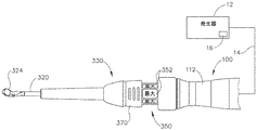
図4〜6は、上述のシステム(10)の器具(20)として使用され得る別の例示的な超音波外科用器具(310)を示す。以下に説明する違い以外には、本例の器具(310)は、器具(110)及び器具(210)と実質的な類似性を有する。したがって、器具(310)は、器具(20、110、210)に関する上述の教示の内の少なくとも一部に従って構築及び動作されてもよい。器具(310)は、ほぼ同時に、組織を切開し、組織(例えば、血管など)を封着又は接合するように動作可能である。本例の器具(310)は、メスとして使用されるように構成される。以下でより詳細に記載されるように、器具(310)は、起動特徴部への改良されたアクセス及び電力モード選択特徴部への改良されたアクセスを提供する。 FIGS. 4-6 show another exemplary ultrasonic surgical instrument (310) that can be used as the instrument (20) of the system (10) described above. Except for the differences described below, the instrument (310) of this example has substantial similarities to the instrument (110) and the instrument (210). Thus, the instrument (310) may be constructed and operated according to at least some of the above teachings regarding the instrument (20, 110, 210). The instrument (310) can operate at about the same time to make an incision in the tissue and seal or join the tissue (eg, blood vessel, etc.). The instrument (310) of this example is configured to be used as a scalpel. As described in more detail below, the appliance (310) provides improved access to the activation feature and improved access to the power mode selection feature.
図4〜5Bに示されるように、本例の器具(310)は、トランスデューサアセンブリ(100)、音響導波管(320)、及び囲い板アセンブリ(330)を備える。導波管(320)の遠位端は、超音波ブレード(324)を含む。超音波ブレード(324)は、上述の超音波ブレード(124)と同様に構成されてもよい。あるいは、超音波ブレード(324)は、上述の超音波ブレード(252)と同様に構成されてもよい。なお別の代替案として、超音波ブレード(324)は、本明細書における他の教示のうちのいずれかに従って、かつ/又は本明細書に引用される様々な参考文献の教示のうちのいずれかに従って構成されてもよい。ブレード(324)に使用され得る他の好適な構成は、本明細書の教示を考慮することにより当業者には明らかになるであろう。 As shown in FIGS. 4-5B, the instrument (310) of this example includes a transducer assembly (100), an acoustic waveguide (320), and an enclosure assembly (330). The distal end of the waveguide (320) includes an ultrasonic blade (324). The ultrasonic blade (324) may be configured in the same manner as the ultrasonic blade (124) described above. Alternatively, the ultrasonic blade (324) may be configured in the same manner as the ultrasonic blade (252) described above. Yet another alternative is that the ultrasonic blade (324) follows any of the other teachings herein and / or any of the teachings of the various references cited herein. It may be configured according to. Other suitable configurations that may be used for the blade (324) will become apparent to those skilled in the art by considering the teachings herein.
以下でより詳細に記載されるように、導波管(320)は、超音波振動をトランスデューサアセンブリ(100)から超音波ブレード(324)に伝達し、それによって組織を切断及び/又は封着するように構成される。囲い板(330)の近位端は、トランスデューサアセンブリ(100)の遠位端とねじ込み連結する。囲い板(330)は、囲い板(330)を近位端から遠位端まで完全に貫通する内部ボア(図示せず)を画定し、それによって近位開口部及び遠位開口部を画定する。導波管(320)は、導波管(320)が囲い板(330)の近位開口部を介してトランスデューサアセンブリ(100)とねじ込み連結され得るように、囲い板(330)の内部ボア内に配設される。超音波ブレード(324)を含む導波管(320)の遠位部分は、囲い板(330)の遠位開口部を介して囲い板(330)の遠位端から遠位方向に突出する。 As described in more detail below, the waveguide (320) transmits ultrasonic vibrations from the transducer assembly (100) to the ultrasonic blade (324), thereby cutting and / or sealing the tissue. It is configured as follows. The proximal end of the enclosure (330) is screwed into connection with the distal end of the transducer assembly (100). The enclosure (330) defines an internal bore (not shown) that completely penetrates the enclosure (330) from the proximal end to the distal end, thereby defining the proximal and distal openings. .. The waveguide (320) is in the internal bore of the enclosure (330) so that the waveguide (320) can be screwed into the transducer assembly (100) through the proximal opening of the enclosure (330). It is arranged in. The distal portion of the waveguide (320), including the ultrasonic blade (324), projects distally from the distal end of the enclosure (330) through the distal opening of the enclosure (330).
トランスデューサアセンブリ(100)は、上述のトランスデューサアセンブリ(100)と実質的に類似するか、又は同一である。具体的には、本例のトランスデューサ(100)は、ケーブル(14)を介して発生器(12)に連結されるが、トランスデューサアセンブリ(100)の代わりにコードレストランスデューサであってよいことを理解されたい。トランスデューサアセンブリ(100)によって生成された超音波振動は、囲い板(330)を通って延在する音響導波管(320)に沿って伝達されて超音波ブレード(324)に達する。上述のように、超音波ブレード(324)が起動状態(すなわち、超音波振動している)にあるとき、超音波ブレード(324)は、組織を効率的に切開及び封着するように動作可能である。導波管(320)が、導波管(320)を通って伝達される機械的振動を増幅するように構成され得ることを理解されたい。更に、導波管(320)は、導波管(320)に沿った長手方向の振動のゲインを制御するように動作可能な特徴部、及び/又は導波管(20)を系の共振周波数に同調させる特徴部を含み得る。 The transducer assembly (100) is substantially similar to or identical to the transducer assembly (100) described above. Specifically, it is understood that the transducer (100) of this example is connected to the generator (12) via a cable (14), but may be a cordless transducer instead of the transducer assembly (100). I want to. The ultrasonic vibration generated by the transducer assembly (100) is transmitted along the acoustic waveguide (320) extending through the enclosure (330) and reaches the ultrasonic blade (324). As mentioned above, when the ultrasonic blade (324) is in the activated state (ie, ultrasonically vibrating), the ultrasonic blade (324) can operate to efficiently incis and seal the tissue. Is. It should be understood that the waveguide (320) may be configured to amplify the mechanical vibrations transmitted through the waveguide (320). Further, the waveguide (320) has a feature portion that can operate to control the gain of vibration in the longitudinal direction along the waveguide (320), and / or the resonant frequency of the waveguide (20). It may include a feature that is tuned to.
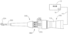
本例の器具(310)は、二組のアクチベータ(350、360)を含み、その作動が、2つの異なる超音波電力レベル又はモードでのトランスデューサ(100)及びブレード(324)の起動をもたらす。アクチベータ(350)は、アクチベータ(360)に対して近位に位置する。アクチベータ(350)は、環状アレイのボタン(352)を含む。アクチベータ(360)も、環状アレイのボタン(362)を含む。各アレイのボタン(352、362)は、上述のボタン(236)と同様に構成され、動作可能であってもよい。あるいは、各アレイのボタン(352、362)は、任意の他の好適な構成を有してもよい。例えば、各アレイのボタン(352,362)は、薄膜スイッチのアレイを含んでもよい。各アクチベータ(350,360)を形成するために使用され得る他の好適な構成要素及び構成は、本明細書の教示を考慮することにより当業者には明らかになるであろう。 The instrument (310) of this example includes two sets of activators (350, 360), the operation of which results in activation of the transducer (100) and blade (324) at two different ultrasonic power levels or modes. The activator (350) is located proximal to the activator (360). The activator (350) includes a button (352) in an annular array. The activator (360) also includes a ring-shaped array button (362). The buttons (352, 362) of each array may be configured and operable in the same manner as the buttons (236) described above. Alternatively, the buttons (352, 362) in each array may have any other suitable configuration. For example, the buttons (352,362) in each array may include an array of thin film switches. Other suitable components and configurations that can be used to form each activator (350, 360) will be apparent to those skilled in the art by considering the teachings herein.
以下でより詳細に記載されるように、アクチベータ(350)は、比較的低い超音波電力レベルでのトランスデューサ(100)及びブレード(324)の起動を提供する一方、アクチベータ(360)は、比較的高い超音波電力レベルでのトランスデューサ(100)及びブレード(324)の起動を提供する。そのため、いくつかの例では、操作者がボタン(352)のうちの1つを作動させると、操作者の選択がケーブル(14)を介して発生器(12)の制御回路(16)に戻って伝達され、制御回路(16)は、低電力起動モードに従って発生器(12)から電力を伝達する。同様に、操作者がボタン(362)のうちの1つを作動させると、操作者の選択がケーブル(14)を介して発生器(12)の制御回路(16)に戻って伝達され、制御回路(16)は、高電力起動モードに従って発生器(12)から電力を伝達する。制御回路(16)がこの機能性を提供するように構成され得る様々な方法は、本明細書の教示を考慮することにより当業者には明らかになるであろう。 As described in more detail below, the activator (350) provides activation of the transducers (100) and blades (324) at relatively low ultrasonic power levels, while the activator (360) is relatively Provides activation of transducers (100) and blades (324) at high ultrasonic power levels. So, in some examples, when the operator activates one of the buttons (352), the operator's choice returns to the control circuit (16) of the generator (12) via the cable (14). The control circuit (16) transfers power from the generator (12) according to the low power start mode. Similarly, when the operator activates one of the buttons (362), the operator's selection is transmitted back to the control circuit (16) of the generator (12) via the cable (14) for control. The circuit (16) transfers power from the generator (12) according to the high power start mode. Various methods by which the control circuit (16) can be configured to provide this functionality will become apparent to those skilled in the art by considering the teachings herein.
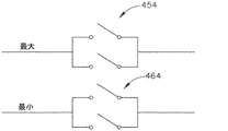
囲い板アセンブリ(330)は、アクチベータ(350、360)を選択的に被覆又は露出するために第1の位置(図4、5B)と第2の位置(図5A)との間で移動可能なスライド可能なリング(370)を含む。特に、スライド可能なリング(370)が図4及び5Bに示される第1の位置にあるとき、スライド可能なリング(370)は、アクチベータ(350)を被覆し、アクチベータ(360)を露出したままにする。したがって、スライド可能なリング(370)が第1の位置にあるとき、操作者は、ボタン(362)を作動させることができるが、ボタン(352)を作動させることはできない。スライド可能なリング(370)が図5Aに示される第2の位置にあるとき、スライド可能なリング(370)は、アクチベータ(360)を被覆し、アクチベータ(350)を露出したままにする。したがって、スライド可能なリング(370)が第2の位置にあるとき、操作者は、ボタン(352)を作動させることができるが、ボタン(362)を作動させることはできない。 The enclosure assembly (330) is movable between a first position (FIGS. 4 and 5B) and a second position (FIG. 5A) to selectively cover or expose the activator (350, 360). Includes a slidable ring (370). In particular, when the slidable ring (370) is in the first position shown in FIGS. 4 and 5B, the slidable ring (370) covers the activator (350) and leaves the activator (360) exposed. To. Thus, when the slidable ring (370) is in the first position, the operator can activate the button (362) but not the button (352). When the slidable ring (370) is in the second position shown in FIG. 5A, the slidable ring (370) covers the activator (360) and leaves the activator (350) exposed. Thus, when the slidable ring (370) is in the second position, the operator can activate the button (352) but not the button (362).
スライド可能なリング(370を第1の位置に位置付けることは、「最小」電力モードの器具を提供し、アクチベータ(350)は、比較的低い超音波電力レベルでのトランスデューサ(100)及びブレード(324)の起動を提供することになる一方、第2の位置にあるスライド可能なリング(370)は、「最大」電力モードの器具を提供し、アクチベータ(350)は、比較的高い超音波電力レベルでのトランスデューサ(100)及びブレード(324)の起動を提供することになることは、前述のことから理解されたい。アクチベータ(350、360)は、器具(310)がどの電力モードにあるかを示す可視指示を提供するためにしるし(例えば、それぞれ「最小」及び「最大」の文字標示など)を含み得る。しるしがとり得る様々な好適な形態は、本明細書の教示を考慮することにより当業者には明らかになるであろう。 Sliding ring (positioning 370 in the first position provides an instrument in "minimum" power mode, the activator (350) is a transducer (100) and blade (324) at relatively low ultrasonic power levels. ) Will be provided, while the slideable ring (370) in the second position provides the instrument in "maximum" power mode, and the transducer (350) has a relatively high ultrasonic power level. It should be understood from the above that it will provide activation of the transducer (100) and blade (324) in the activator (350, 360) which power mode the appliance (310) is in. The indications may include indications (eg, "minimum" and "maximum" character markings, respectively) to provide the indications, and various suitable forms in which the indications may be taken by taking into account the teachings herein. It will be clear to those in the art.
上述のように、スライド可能なリング(370)が遠位位置にあるとき、器具(310)は、第1のレベルの超音波エネルギーによってブレード(324)で動作可能であり、スライド可能なリング(370)が近位位置にあるとき、器具(310)は、第2のレベルの超音波エネルギーによってブレード(324)で動作可能である。あくまで一例として、スライド可能なリング(370)の遠位端が「最大」電力を提供する一方、スライド可能なリング(370)の近位端が「最小」電力を提供するように、第1のレベルのエネルギーは、第2のレベルのエネルギーを上回る場合がある。言うまでもなく、これは単なる例証的な非限定的な例である。当業者であれば、所望の場合には上述の関連性は容易に逆転することができることをすぐに理解するであろう。すなわち、スライド可能なリング(370)の遠位位置が「最小」電力を提供する一方、スライド可能なリング(370)の近位位置が「最大」電力を提供するように、第1のレベルのエネルギーが第2のレベルのエネルギーよりも低い場合がある。スライド可能なリング(370)が、遠位位置と近位位置との間の様々な他の位置に移動可能であり得、選択できる更なる電力レベルが提供され得ることも理解されたい。更に、スライド可能なリング(370)は、異なるエネルギー様式間の切り替えを提供するように動作可能であり得る。例えば、スライド可能なリング(370)は、ブレード(324)での超音波エネルギーの提供とブレード(324)でのRFエネルギーの提供との間で切り替えるように動作可能であり得る。異なる起動モードと関連付けられ得る他の好適な動作特性は、本明細書の教示を考慮することにより当業者には明らかになるであろう。 As mentioned above, when the slidable ring (370) is in the distal position, the instrument (310) can be actuated on the blade (324) by the first level of ultrasonic energy and the slidable ring (310). When the 370) is in the proximal position, the instrument (310) can operate on the blade (324) with a second level of ultrasonic energy. As an example, the first, such that the distal end of the slidable ring (370) provides the "maximum" power, while the proximal end of the slidable ring (370) provides the "minimum" power. The energy of the level may exceed the energy of the second level. Needless to say, this is just an exemplary, non-limiting example. Those skilled in the art will immediately appreciate that the above associations can be easily reversed if desired. That is, the distal position of the slidable ring (370) provides the "minimum" power, while the proximal position of the slidable ring (370) provides the "maximum" power. The energy may be lower than the second level of energy. It should also be appreciated that the slidable ring (370) may be movable to various other positions between the distal and proximal positions, providing additional power levels to choose from. In addition, the slidable ring (370) may be operational to provide switching between different energy modes. For example, the slidable ring (370) may be operable to switch between providing ultrasonic energy at the blade (324) and providing RF energy at the blade (324). Other suitable operating characteristics that may be associated with different activation modes will become apparent to those skilled in the art by considering the teachings herein.
示される例では、スライド可能なリング(370)は、戻り止め機構(図示せず)などの係止機構によって第1及び第2の位置で固定可能である。例えば、スライド可能なリング(370)がいったん第1の位置に置かれると、戻り止め機構は、遠位方向(ブレード(324)に向かって)の十分な力がなくてもスライド可能なリング(370)を第1の位置に維持するように構成される。同様に、スライド可能なリング(370)がいったん第2の位置に置かれると、戻り止め機構は、近位方向の十分な力がなくてもスライド可能なリング(370)を第2の位置に維持するように構成される。他の例では、戻り止め機構は、作動又は押し下げられると、戻り止め機構を開放し、囲い板(330)に対してスライド可能なリング(370)が移動することを許可するボタン又は他の特徴部と関連付けられ得る。戻り止め特徴部がそれでもまだ、操作者が器具(310)のその握りを大幅に変えることを必要とせずに、操作者がスライド可能なリング(370)を移動させることを許可することを理解されたい。例えば、操作者は、操作者の残りの指を所定位置に固定して留めたまま、単一の指(例えば、人差し指又は親指)のみでスライド可能なリング(370)を長手方向に平行移動させることができる。戻り止め特徴部がとり得る様々な好適な形態は、本明細書の教示を考慮することにより当業者には明らかになるであろう。 In the example shown, the slidable ring (370) can be fixed in the first and second positions by a locking mechanism such as a detent mechanism (not shown). For example, once the slidable ring (370) is in the first position, the detent mechanism is a slidable ring (towards the blade (324)) without sufficient force. 370) is configured to be maintained in the first position. Similarly, once the slidable ring (370) is placed in the second position, the detent mechanism will place the slidable ring (370) in the second position without sufficient force in the proximal direction. Configured to maintain. In another example, the detent mechanism is a button or other feature that, when actuated or pushed down, opens the detent mechanism and allows the slidable ring (370) to move relative to the enclosure (330). Can be associated with a department. It is understood that the detent feature still allows the operator to move the slidable ring (370) without requiring the operator to significantly change its grip on the instrument (310). I want to. For example, the operator translates the slidable ring (370) in the longitudinal direction with only one finger (eg, index finger or thumb) while retaining the operator's remaining fingers in place. be able to. Various suitable forms that the detent feature may take will be apparent to those skilled in the art by considering the teachings herein.
いくつかの例では、スライド可能なリング(370)は、スライド可能なリング(370)が第1又は第2の位置のいずれかに置かれなければならず、スライド可能なリング(370)が第1及び第2の位置の間の中間位置、又は第1若しくは第2の位置ではない別の位置に置かれてはならないように構成されてもよい。いくつかのかかる例では、スライド可能なリング(370)は、例えば、操作者がスライド可能なリング(370)を第1又は第2の位置まで完全に移動させ損ねた場合にスライド可能なリング(370)を第1又は第2の位置のうちの1つに引き寄せるように構成された付勢要素と関連付けられ得る。しかしながら、他の例では、スライド可能なリング(370)は、第1及び第2の位置以外の位置(例えば、任意の動作モードと関連付けられていない)に置かれることが許容され得る。例えば、スライド可能なリング(370)は、第1及び第2の位置の間にある位置に置かれてもよい。上述のように、スライド可能なリング(370)の中間位置は、中間電力モードと対応してもよい。別の単なる例証的な代替案として、スライド可能なリング(370)は、スライド可能なリング(370)が遠位及び近位位置の間の中間位置に位置するときに、両方のアクチベータ(350、360)を動作不可能にし得る。したがって、スライド可能なリング(370)は、スライド可能なリング(370)が遠位及び近位位置の間の中間位置に位置付けられる場合、「オフ」位置と見なされ得る。 In some examples, the slidable ring (370) requires the slidable ring (370) to be placed in either the first or second position, with the slidable ring (370) being the first. It may be configured so that it must not be placed in an intermediate position between the first and second positions, or in a position other than the first or second position. In some such examples, the slidable ring (370) is, for example, a slidable ring (370) if the operator fails to completely move the slidable ring (370) to the first or second position. 370) may be associated with an urging element configured to attract 370) to one of the first or second positions. However, in another example, the slidable ring (370) may be allowed to be placed in a position other than the first and second positions (eg, not associated with any mode of operation). For example, the slidable ring (370) may be placed in a position between the first and second positions. As mentioned above, the intermediate position of the slidable ring (370) may correspond to the intermediate power mode. As another mere exemplary alternative, the slidable ring (370) is used when the slidable ring (370) is located in the middle position between the distal and proximal positions, both activators (350,). 360) can be inoperable. Therefore, the slidable ring (370) can be considered an "off" position if the slidable ring (370) is positioned in the middle position between the distal and proximal positions.
本例の器具(310)が2つのアクチベータ(350、360)を含む一方、代替の例では、3つ又は4つ以上などの2つを超えるアクチベータ(350,360)が存在してもよい。かかる例では、スライド可能なリング(370)は、1つのみのアクチベータ(350、360)へのアクセスを許可する一方で、他のアクチベータ(350、360)のうちの1つ又は2つ以上へのアクセスを防止するように構成されてもよい。いくつかのかかる例では、アクチベータ(350、360)の追加又は代替の構成に適応するために1つを超えるスライド可能なリング(370)が存在し得る。更に、示されるように、各アクチベータ(350,360)は、それぞれの組の4つのボタン(352、362)を含む。あるいは、各アクチベータ(350、360)は、それぞれの組の3つ以下のボタン(352、362)、又は5つ若しくは6つ以上のボタン(352、362)を含み得る。更に、アクチベータ(350)と関連付けられたボタン(352)の数は、アクチベータ(360)と関連付けられたボタン(362)の数と異なる場合がある。 While the instrument (310) of this example includes two activators (350, 360), in an alternative example, there may be more than two activators (350, 360), such as three or four or more. In such an example, the slidable ring (370) allows access to only one activator (350, 360), while to one or more of the other activators (350, 360). May be configured to prevent access to. In some such examples, there may be more than one slidable ring (370) to accommodate additional or alternative configurations of activators (350, 360). Further, as shown, each activator (350,360) includes each set of four buttons (352,362). Alternatively, each activator (350, 360) may include a set of 3 or less buttons (352, 362), or 5 or 6 or more buttons (352, 362). Further, the number of buttons (352) associated with the activator (350) may differ from the number of buttons (362) associated with the activator (360).
図6は、器具(310)のブロック概略図を示す。図6に示されるように、器具(310)は、トランスデューサ(326)、トランスデューサ回路(328)、第1のアクチベータ(350)と関連付けられた第1のスイッチ(354)、及び第2のアクチベータ(360)と関連付けられた第2のスイッチ(364)を含むトランスデューサアセンブリ(100)を含む。器具(310)は、トランスデューサ回路(328)を導波管(320)と動作可能に接続するライン(356)、及びトランスデューサ回路(328)を導波管(320)(と動作可能に接続する別のライン(366)を更に含む。いくつかの例では、スイッチ(354)は、スライド可能なリング(370)が第1の位置にあるときに、閉鎖位置に移動され得る。その後、ボタン(352)が作動すると、例えば、発生器(12)は回路(328)を通して電力を伝達し、結果として得られた超音波エネルギーが第1の起動モードに従ってブレード(324)に送達される。同様に、スイッチ(364)は、スライド可能なリング(370)が第2の位置にあるときに、閉鎖位置に移動され得る。したがって、ボタン(362)が作動すると、例えば、発生器(12)は回路(3218)を通して導波管(320)に電力を伝達し、結果として得られた超音波エネルギーが第2の起動モードに従ってブレード(324)に送達される。 FIG. 6 shows a schematic block view of the appliance (310). As shown in FIG. 6, the instrument (310) includes a transducer (326), a transducer circuit (328), a first switch (354) associated with a first activator (350), and a second activator ( Includes a transducer assembly (100) that includes a second switch (364) associated with 360). The instrument (310) is a line (356) that operably connects the transducer circuit (328) to the waveguide (320), and another that operably connects the transducer circuit (328) to the waveguide (320). In some examples, the switch (354) can be moved to the closed position when the slidable ring (370) is in the first position. Then the button (352). ) Is activated, for example, the generator (12) transfers power through the circuit (328) and the resulting ultrasonic energy is delivered to the blade (324) according to the first activation mode. The switch (364) can be moved to the closed position when the slidable ring (370) is in the second position. Therefore, when the button (362) is activated, for example, the generator (12) is in the circuit (12). Power is transmitted to the waveguide (320) through the 3218) and the resulting ultrasonic energy is delivered to the blade (324) according to a second activation mode.
代替の例では、スイッチ(354、364)の一方又は両方は、示される様式とは異なって構成されてもよい。例えば、図7を参照して、代替のスイッチ(454、464)は各々、スイッチ(354、364)に関して説明された様式と同じ又は異なる様式で開閉し得る一組のスイッチを並列に含む。スイッチ(354、364、454、464)の他の好適な構成は、本明細書の教示を考慮することにより当業者には明らかになるであろう。トランスデューサ回路(328)が、図1に示され、上述した制御回路(34)と類似した様式で構成され得ることを理解されたい。 In an alternative example, one or both of the switches (354, 364) may be configured differently than shown. For example, with reference to FIG. 7, each alternative switch (454, 464) includes a set of switches in parallel that can be opened and closed in the same or different manner as described for the switch (354,364). Other suitable configurations of switches (354, 364, 454, 464) will be apparent to those skilled in the art by considering the teachings herein. It should be understood that the transducer circuit (328) can be configured in a manner similar to that of the control circuit (34) shown in FIG. 1 and described above.
スライド可能なリング(370)が2つの異なる構成で提供され得ることは、前述から理解されたい。1つの例示的な構成において、スライド可能なリング(370)は、単に、ボタン(352、362)を選択的に被覆して、それによりボタン(352、362)が作動されることを防止する機械的シールドとして機能する。例えば、スライド可能なリング(370)が遠位位置にあるとき、スライド可能なリング(370)は、ボタン(362)を被覆し、それによりボタン(362)が作動されることを防止するが、ボタン(352)へのアクセスを提供し、それによりボタン(352)が作動されることを許可する。逆に、スライド可能なリング(370)が近位位置にあるとき、スライド可能なリング(370)は、ボタン(352)を被覆し、それによりボタン(352)が作動されることを防止するが、ボタン(362)へのアクセスを提供し、それによりボタン(362)が作動されることを許可する。スライド可能なリング(370)が、単に、ボタン(352、362)へのアクセスを選択的に妨げる機械的カバーとして機能するいくつかのかかる変形例では、スライド可能なリング(370)は、あらゆる種類のスイッチと係合しない。かかる変形例では、各組のボタン(352、362)は、各組のボタン(352、362)が対応する超音波電力レベルでブレード(324)を起動させることを可能にするそれぞれの回路に配線される。言い換えれば、ボタン(352)は、第1の超音波電力レベルでブレード(324)を起動させるための専用の回路に配線されてもよい一方、ボタン(362)は、第1の超音波電力レベルでブレード(324)を起動させる別個の専用の回路に配線されてもよい。したがって、スライド可能なリング(370)の長手方向位置付けは、あらゆる電気回路構成に影響を及ぼさず、単に、ボタン(352、362)のアクセス性に影響を及ぼす。 It should be understood from the above that the slidable ring (370) can be provided in two different configurations. In one exemplary configuration, the slidable ring (370) is simply a machine that selectively covers the buttons (352, 362), thereby preventing the buttons (352, 362) from being activated. Functions as a target shield. For example, when the slidable ring (370) is in the distal position, the slidable ring (370) covers the button (362), thereby preventing the button (362) from being activated. Provides access to the button (352), thereby allowing the button (352) to be activated. Conversely, when the slidable ring (370) is in the proximal position, the slidable ring (370) covers the button (352), thereby preventing the button (352) from being activated. , Provide access to the button (362), thereby allowing the button (362) to be activated. In some such variations where the slidable ring (370) simply acts as a mechanical cover that selectively interferes with access to the buttons (352, 362), the slidable ring (370) is of any kind. Does not engage with the switch. In such a variant, each set of buttons (352, 362) is wired to a respective circuit that allows each set of buttons (352, 362) to activate the blade (324) at the corresponding ultrasonic power level. Will be done. In other words, the button (352) may be wired to a dedicated circuit to activate the blade (324) at the first ultrasonic power level, while the button (362) may be wired to the first ultrasonic power level. It may be wired to a separate dedicated circuit that activates the blade (324) at. Therefore, the longitudinal positioning of the slidable ring (370) does not affect any electrical circuit configuration, but merely the accessibility of the buttons (352, 362).
しかしながら、別の例示的な構成において、スライド可能なリング(370)は、実際には、スライド可能なリング(370)が位置付けられた位置に基づいて、特定の電力モードを選択するスイッチを作動させる。いくつかのかかる変形例では、スライド可能なリング(370)が遠位位置にあるとき、スライド可能なリング(370)は、第1の電力レベルでの超音波ブレード(324)の起動と関連付けられたスイッチを閉じる(入れる)。スライド可能なリング(370)が近位位置にあるとき、スライド可能なリング(370)は、第2の電力レベルでの超音波ブレード(324)の起動と関連付けられたスイッチを閉じる(入れる)。かかる変形例では、ボタン(352)は、必ずしも、ボタン(362)が配線された回路とは別個の回路に配線されていない。いくつかのかかる変形例では、スライド可能なリング(370)が除去されることになると、ボタン(352)は、ボタン(362)と同じ超音波電力レベルで超音波ブレード(324)を起動させることになる。したがって、ボタン(352)は、ボタン(362)と共に単一の組のボタン(2つの別個の長手方向に離間された組のボタン(352、362)ではなく)に統合されてもよく、統合された組のボタンは、スライド可能なリング(370)の長手方向に位置にかかわらずアクセス可能であることを理解されたい。 However, in another exemplary configuration, the slidable ring (370) actually activates a switch that selects a particular power mode based on where the slidable ring (370) is located. .. In some such variants, when the slidable ring (370) is in the distal position, the slidable ring (370) is associated with activation of the ultrasonic blade (324) at the first power level. Close (turn on) the switch. When the slidable ring (370) is in the proximal position, the slidable ring (370) closes (turns on) the switch associated with the activation of the ultrasonic blade (324) at the second power level. In such a modification, the button (352) is not necessarily wired to a circuit separate from the circuit to which the button (362) is wired. In some such variants, when the slidable ring (370) is to be removed, the button (352) activates the ultrasonic blade (324) at the same ultrasonic power level as the button (362). become. Thus, the button (352) may be integrated with the button (362) into a single set of buttons (rather than two separate, longitudinally spaced pairs of buttons (352, 362)). It should be understood that the set of buttons is accessible regardless of their position in the longitudinal direction of the slidable ring (370).
この例の別の変形形態として、制御回路は、制御回路がスライド可能なリングの長手方向位置に基づいて超音波電力レベルを選択するように、スライド可能なリング(370)の長手方向位置を感知するように動作可能である特徴部を含み得る。スライド可能なリング(370)が単にボタン(352、362)へのアクセスを制御する前述の例とは異なり、この代替の例では、スライド可能なリング(370)の長手方向の位置付けは、実際には、ボタン(352、362)のアクセス性に影響を及ぼすことに加えて、電気回路構成を変化させることを理解されたい。 As another variant of this example, the control circuit senses the longitudinal position of the slidable ring (370) so that the control circuit selects the ultrasonic power level based on the longitudinal position of the slidable ring. It may include features that are capable of acting as such. In this alternative example, the longitudinal positioning of the slidable ring (370) is actually different from the previous example where the slidable ring (370) simply controls access to the buttons (352, 362). It should be understood that, in addition to affecting the accessibility of the buttons (352, 362), it alters the electrical circuit configuration.
III.例示的な組み合わせ
以下の実施例は、本明細書の教示を組み合わせるか又は適用することができる様々な非網羅的な方法に関する。以下の実施例は、本出願における又は本出願の後の出願におけるどの時点でも提示され得るいずれの請求項の適用範囲をも限定することを目的としたものではないことを理解されたい。一切の権利放棄を意図するものではない。以下の実施例は単なる例証目的で与えられるものにすぎない。本明細書の様々な教示は、多くの他の方法で配置及び適用され得ることが企図される。また、いくつかの変形形態では、以下の実施例で言及される特定の特徴を省略してもよいことも企図される。したがって、本発明者によって、又は本発明者の利益となる継承者によって、後日、そうである旨が明示的に示されない限り、以下に言及される態様又は特徴のいずれも重要なものとしてみなされるべきではない。以下に言及される特徴以外の更なる特徴を含む請求項が本出願において、又は本出願に関連する後の出願において示される場合、これらの更なる特徴は、特許性に関連するいずれの理由によって追加されたものとしても仮定されるべきではない。
III. Illustrative Combinations The following examples relate to various non-exhaustive methods to which the teachings herein can be combined or applied. It should be understood that the following examples are not intended to limit the scope of any claim that may be presented at any time in this application or in subsequent applications. It is not intended to be a waiver of any rights. The following examples are given for illustration purposes only. It is contemplated that the various teachings herein may be arranged and applied in many other ways. It is also contemplated that in some variants, certain features referred to in the examples below may be omitted. Accordingly, any of the aspects or features referred to below will be deemed important unless expressly indicated at a later date by the inventor or by a successor in the interest of the inventor. Should not be. Where a claim containing additional features other than those mentioned below is presented in this application or in a later application related to this application, these additional features may be for any reason relating to patentability. It should not be assumed as an addition.
(実施例1)
超音波器具であって、(a)本体であって、長手方向軸を画定し、超音波トランスデューサを受容するように構成されている、本体と、(b)作動アセンブリであって、(i)第1の起動部材と、(ii)第2の起動部材と、を備える、作動アセンブリと、(c)シャフトアセンブリであって、音響導波管を備える、シャフトアセンブリと、(d)音響導波管と音響通信する超音波ブレードであって、第1の起動部材が、第1の電力モードで超音波ブレードの起動を引き起こすように動作可能であり、第2の起動部材が、第2の電力モードで超音波ブレードの起動を引き起こすように動作可能である、超音波ブレードと、(e)第1の位置と第2の位置との間で移動するように構成された移動可能な部材と、を備え、移動可能な部材は、移動可能な部材が第1の位置にあるときに、第1の起動部材へのアクセスを許可し、かつ第2の起動部材へのアクセスを防止するように構成されており、移動可能な部材は、移動可能な部材が第2の位置にあるときに、第2の起動部材へのアクセスを許可し、かつ第1の起動部材へのアクセスを防止するように構成されている、超音波器具。
(Example 1)
An ultrasonic instrument, (a) a body, a body that defines a longitudinal axis and is configured to receive an ultrasonic transducer, and (b) an actuating assembly, (i). An actuating assembly comprising a first activation member and (ii) a second activation member, (c) a shaft assembly comprising an acoustic waveguide, and (d) an acoustic waveguide. An ultrasonic blade that acoustically communicates with a tube, in which the first activation member can operate to trigger the activation of the ultrasonic blade in the first power mode, and the second activation member is the second power. An ultrasonic blade that is capable of operating to cause activation of the ultrasonic blade in mode, and (e) a movable member configured to move between a first position and a second position. The movable member is configured to allow access to the first activation member and prevent access to the second activation member when the movable member is in the first position. The movable member is so as to allow access to the second activation member and prevent access to the first activation member when the movable member is in the second position. It is composed of ultrasonic instruments.
(実施例2)
少なくとも1つのスイッチを更に備え、少なくとも1つのスイッチが、作動アセンブリ又は移動可能な部材と通信する、実施例1に記載の超音波器具。
(Example 2)
The ultrasonic instrument according to Example 1, further comprising at least one switch, wherein the at least one switch communicates with a working assembly or a movable member.
(実施例3)
少なくとも1つのスイッチが、第1の起動部材の作動に応じて、開放状態から閉鎖状態に移行するように構成された第1のスイッチを含む、実施例2に記載の超音波器具。
(Example 3)
The ultrasonic device according to a second embodiment, wherein at least one switch includes a first switch configured to transition from an open state to a closed state in response to an operation of a first activation member.
(実施例4)
少なくとも1つのスイッチが、第2の起動部材の作動に応じて、開放状態から閉鎖状態に移行するように構成された第2のスイッチを含む、実施例3に記載の超音波器具。
(Example 4)
The ultrasonic device according to a third embodiment, wherein at least one switch includes a second switch configured to transition from an open state to a closed state in response to an operation of a second activation member.
(実施例5)
少なくとも1つのスイッチが、移動可能な部材の第1の位置と第2の位置との間の移動に応じて、開放状態から閉鎖状態に移行するように構成されている、実施例2に記載の超音波器具。
(Example 5)
The second embodiment, wherein at least one switch is configured to transition from an open state to a closed state in response to movement of the movable member between a first position and a second position. Ultrasonic instrument.
(実施例6)
第1の起動部材が、第1の複数のボタンを備える、実施例1〜5のいずれか1つ又は2つ以上に記載の超音波器具。
(Example 6)
The ultrasonic device according to any one or two or more of Examples 1 to 5, wherein the first activation member includes a first plurality of buttons.
(実施例7)
第1の複数のボタンが、長手方向軸を中心に環状アレイ状に配置されている、実施例6に記載の超音波器具。
(Example 7)
The ultrasonic device according to a sixth embodiment, wherein the first plurality of buttons are arranged in an annular array around the longitudinal axis.
(実施例8)
第2の起動部材が、第2の複数のボタンを備える、実施例7に記載の超音波器具。
(Example 8)
The ultrasonic device according to a seventh embodiment, wherein the second activation member includes a second plurality of buttons.
(実施例9)
第2の複数のボタンが、長手方向軸を中心に環状アレイ状に配置されている、実施例8に記載の超音波器具。
(Example 9)
The ultrasonic instrument according to Example 8, wherein the second plurality of buttons are arranged in an annular array around the longitudinal axis.
(実施例10)
第2の起動部材が、第2の複数のボタンを備える、実施例6に記載の超音波器具。
(Example 10)
The ultrasonic device according to a sixth embodiment, wherein the second activation member includes a second plurality of buttons.
(実施例11)
第2の複数のボタンが、第1の複数のボタンに対して遠位に位置付けられている、実施例10に記載の超音波器具。
(Example 11)
The ultrasonic device according to Example 10, wherein the second plurality of buttons are located distal to the first plurality of buttons.
(実施例12)
移動可能な部材が、第1の位置と第2の位置との間で本体に沿って平行移動するように構成されている、実施例1〜11のいずれか1つ又は2つ以上に記載の超音波器具。
(Example 12)
The movable member according to any one or more of Examples 1 to 11, wherein the movable member is configured to translate between the first position and the second position along the main body. Ultrasonic instrument.
(実施例13)
移動可能な部材が、スライド可能なリングを含む、実施例1〜12のいずれか1つ又は2つ以上に記載の超音波器具。
(Example 13)
The ultrasonic device according to any one or two or more of Examples 1 to 12, wherein the movable member includes a slidable ring.
(実施例14)
移動可能な部材を第1の位置に選択的に保持するように構成された第1の組の戻り止め特徴部を更に備える、実施例1〜13のいずれか1つ又は2つ以上に記載の超音波器具。
(Example 14)
The one or more of Examples 1-13, further comprising a first set of detent features configured to selectively hold the movable member in the first position. Ultrasonic instrument.
(実施例15)
移動可能な部材を第2の位置に選択的に保持するように構成された第2の組の戻り止め特徴部を更に備える、実施例1〜14のいずれか1つ又は2つ以上に記載の超音波器具。
(Example 15)
The one or more of Examples 1-14, further comprising a second set of detent features configured to selectively hold the movable member in a second position. Ultrasonic instrument.
(実施例16)
第1の電力モードが、第2の電力モードよりも高いレベルの超音波振動電力を供給し、これにより、第2の起動部材が超音波ブレードの起動を引き起こすように動作可能な電力よりも高い電力で第1の起動部材が超音波ブレードの起動を引き起こすように動作可能になる、実施例1〜15のいずれか1つ又は2つ以上に記載の超音波器具。
(Example 16)
The first power mode provides a higher level of ultrasonic oscillating power than the second power mode, which is higher than the power that the second activation member can operate to trigger the activation of the ultrasonic blades. The ultrasonic instrument according to any one or more of Examples 1 to 15, wherein the first actuating member can be operated by electric power to cause the activation of the ultrasonic blade.
(実施例17)
超音波外科用器具のハンドルアセンブリであって、(a)本体であって、長手方向軸を画定し、超音波トランスデューサを受容するように構成されている、本体と、(b)シャフトアセンブリであって、音響導波管を備える、シャフトアセンブリと、(c)音響導波管と音響通信する超音波ブレードと、(d)作動アセンブリであって、(i)第1の複数のボタンであって、本体の周りに角度をなして配設されている、第1の複数のボタンと、(ii)第2の複数のボタンであって、本体の周りに角度をなして配設されている、第2の複数のボタンと、(iii)第1の複数のボタン又は第2の複数のボタンのうちの一方又は両方が第1の電力レベルで超音波ブレードの起動を引き起こすことを可能にするように動作可能な第1のスイッチと、(iv)第1の複数のボタン又は第2の複数のボタンのうちの一方又は両方が第2の電力レベルで超音波ブレードの起動を引き起こすことを可能にするように動作可能な第2のスイッチと、を備える、作動アセンブリと、(e)移動可能な部材であって、移動可能な部材が、第1の位置と第2の位置との間で本体に対して移動可能であり、移動可能な部材が、移動可能な部材の第1の位置での位置付けに応じて第1のスイッチを作動させるように動作可能であり、移動可能な部材が、移動部材の第2の位置での位置付けに応じて第2のスイッチを作動させるように動作可能である、移動可能な部材と、を備える、超音波外科用器具のハンドルアセンブリ。
(Example 17)
A handle assembly for an ultrasonic surgical instrument, (a) a body, a body that defines a longitudinal axis and is configured to receive an ultrasonic transducer, and (b) a shaft assembly. A shaft assembly comprising an acoustic waveguide, (c) an ultrasonic blade that acoustically communicates with the acoustic waveguide, (d) an actuating assembly, and (i) a first plurality of buttons. A first plurality of buttons arranged at an angle around the main body and (ii) a second plurality of buttons arranged at an angle around the main body. Allowing one or both of the second plurality of buttons and (iii) the first plurality of buttons or the second plurality of buttons to trigger the activation of the ultrasonic blade at the first power level. Allows the first switch to operate and (iv) one or both of the first plurality of buttons or the second plurality of buttons to trigger the activation of the ultrasonic blade at the second power level. An actuating assembly comprising a second switch that is movable so as to (e) a movable member, the movable member of which is a body between a first position and a second position. The movable member is movable with respect to the movable member, and the movable member can be operated so as to operate the first switch according to the position of the movable member in the first position. A handle assembly of an ultrasonic surgical instrument comprising a movable member that is movable to actuate a second switch depending on the position of the member in the second position.
(実施例18)
超音波器具であって、(a)本体であって、長手方向軸を画定し、超音波トランスデューサを受容するように構成されている、本体と、(b)作動アセンブリであって、(i)第1の環状起動部材と、(ii)第2の環状起動部材と、を備える、作動アセンブリと、(c)シャフトアセンブリであって、音響導波管を備える、シャフトアセンブリと、(d)超音波ブレードであって、超音波ブレードが、音響導波管と音響通信し、第1の環状起動部材が、超音波ブレードを第1の電力レベルで起動させるように動作可能であり、第2の環状起動部材が、超音波ブレードを第2の電力レベルで起動させるように動作可能である、超音波ブレードと、(e)本体の一部の周りに配設されたリングであって、第1の位置と第2の位置との間で長手方向軸に沿って移動可能である、リングと、を備え、リングは、リングの第1の位置での位置付けに応じて作動アセンブリが超音波ブレードを第1の電力レベルで起動させることを可能にするように構成されており、リングは、リングの第2の位置での位置付けに応じて作動アセンブリが超音波ブレードを第2の電力レベルで起動させることを可能にするように構成されている、超音波器具。
(Example 18)
An ultrasonic instrument, (a) a body, a body that defines a longitudinal axis and is configured to receive an ultrasonic transducer, and (b) an actuating assembly, (i). An actuating assembly comprising a first annular activation member, (ii) a second annular activation member, (c) a shaft assembly comprising an acoustic waveguide, and (d) an ultrasound. A second, the ultrasonic blade is capable of acoustically communicating with the acoustic waveguide and the first annular activation member activating the ultrasonic blade at the first power level. The first, the annular activation member is the ultrasonic blade and (e) a ring disposed around a part of the body, capable of operating to activate the ultrasonic blade at a second power level. The ring is equipped with a ring, which is movable along the longitudinal axis between the position and the second position, and the ring operates according to the position of the ring in the first position. Configured to allow activation at the first power level, the ring is actuated according to the position of the ring in the second position. The assembly activates the ultrasonic blade at the second power level. An ultrasonic instrument that is configured to allow you to do that.
(実施例19)
リングが、第1の位置及び/又は第2の位置に固定されるように構成されている、実施例18に記載の超音波器具。
(Example 19)
The ultrasonic instrument according to Example 18, wherein the ring is configured to be fixed in a first position and / or a second position.
(実施例20)
リングが、第1の位置及び/又は第2の位置に向かって付勢されるように構成されている、実施例18又は19のうちのいずれか1つ又は2つに記載の超音波器具。
(Example 20)
The ultrasonic instrument according to any one or two of Examples 18 or 19, wherein the ring is configured to be urged towards a first position and / or a second position.
IV.その他
明細書に記載される器具のいずれの変形例も、本明細書で上述されるものに加えて、又はそれらの代わりに、種々の他の特徴を含んでもよいことを理解されたい。あくまで一例として、本明細書で説明する器具のいずれもが、本明細書において、参照することにより組み込まれる種々の参考文献のいずれかで開示される種々の特徴のうちの1つ又は2つ以上を含むこともできる。本明細書の教示は、本明細書の引用文献のいずれかの教示と多数の方法で容易に組み合わせ得るため、本明細書の教示は、本明細書の他の引用文献のいずれかに記載される器具のいずれにも容易に適用され得ることが理解されよう。本明細書の教示が組み込まれ得る他の種類の器具が、当業者には明らかであろう。
IV. Other It should be understood that any modification of the instruments described herein may include various other features in addition to or in place of those described herein. As an example only, any of the instruments described herein is one or more of the various features disclosed herein in any of the various references incorporated by reference. Can also be included. The teachings herein are described in any of the other references herein, as the teachings herein can be easily combined with the teachings of any of the references cited herein in a number of ways. It will be appreciated that it can be easily applied to any of the following instruments. Other types of instruments to which the teachings herein may be incorporated will be apparent to those skilled in the art.
参照により本明細書に援用されると言及されたいかなる特許、刊行物、又は他の開示内容も、全体的に又は部分的に、援用された内容が現行の定義、見解、又は本開示に記載された他の開示内容とあくまで矛盾しない範囲でのみ本明細書に援用されることを認識されたい。それ自体、また必要な範囲で、本明細書に明瞭に記載される開示内容は、参照により本明細書に援用されるあらゆる矛盾する記載に優先するものとする。参照により本明細書に援用されるものとするが、既存の定義、記載、又は本明細書に記載される他の開示文献と矛盾する任意の文献、又はそれらの部分は、援用文献と既存の開示内容との間に矛盾が生じない範囲においてのみ援用されるものとする。 Any patents, publications, or other disclosures referred to herein by reference, in whole or in part, are described in the current definition, opinion, or disclosure. Please be aware that this is incorporated herein only to the extent that it is consistent with the other disclosures made. As such, and to the extent necessary, the disclosures expressly set forth herein shall supersede any contradictory statements incorporated herein by reference. Any document, or portion thereof, that is incorporated herein by reference but is inconsistent with existing definitions, descriptions, or other disclosed documents described herein is in reference and existing. It shall be incorporated only to the extent that there is no contradiction with the disclosed content.
上述の装置の変形例は、医療専門家によって行われる従来の治療及び処置での用途だけでなく、ロボット支援された治療及び処置での用途も有することができる。あくまでも一例として、本明細書の様々な教示は、ロボット手術システム、例えばIntuitive Surgical,Inc.(Sunnyvale,California)によるDAVINCI(商標)システムに容易に組み込まれ得る。同様に、当業者には明らかとなることであるが、本明細書の種々の教示は、その開示が、本明細書において、参照することにより組み込まれる5004年8月31日公開の「Robotic Surgical Tool with Ultrasound Cauterizing and Cutting Instrument」と題された米国特許第6,783,524号の種々の教示と容易に組み合わされ得る。 Modifications of the devices described above can have applications in robot-assisted therapies and procedures as well as in conventional therapies and procedures performed by medical professionals. As an example only, the various teachings herein are described in robotic surgery systems such as Intuitive Surgical, Inc. It can be easily incorporated into the DAVINCI ™ system by (Sunnyvale, California). Similarly, as will be apparent to those skilled in the art, the various teachings herein are incorporated herein by reference in the "Robotic Surgical" published August 31, 5004. It can be easily combined with the various teachings of US Pat. No. 6,783,524 entitled "Tool with Ultrasound Cauterizing and Cutting Instrument".
上述の変形例は、1回の使用後に廃棄されるように設計されてもよく、あるいは、それらは、複数回使用されるように設計されてもよい。いずれか又は両方の場合において、変形例は、少なくとも1回の使用後に再利用のために再調整され得る。再調整は、デバイスの分解工程、それに続く特定の部分の洗浄又は交換工程、及びその後の再組立工程の任意の組み合わせを含み得る。特に、装置のいくつかの変形例は分解することができ、また、装置の任意の数の特定の部分又は部品を、任意の組み合わせで選択的に交換するか又は取り外してもよい。特定の部品の洗浄及び/又は交換に際して、装置のいくつかの変形例を、再調整用の施設において、又は手術の直前に使用者により再組み立てして、その後の使用に供することができる。当業者であれば、デバイスの再調整において、分解、洗浄/交換、及び再組立のための様々な技術を利用することができることを認識するであろう。かかる技術の使用、及び結果として得られる再調整されたデバイスは、全て本発明の範囲内にある。 The modifications described above may be designed to be discarded after a single use, or they may be designed to be used multiple times. In either or both cases, the variants may be readjusted for reuse after at least one use. The readjustment may include any combination of a device disassembly step, followed by a cleaning or replacement step of a particular portion, and a subsequent reassembly step. In particular, some modifications of the device can be disassembled and any number of specific parts or parts of the device may be selectively replaced or removed in any combination. Upon cleaning and / or replacement of certain parts, some modifications of the device may be reassembled by the user in a readjustment facility or shortly before surgery for subsequent use. Those skilled in the art will recognize that various techniques for disassembly, cleaning / replacement, and reassembly can be utilized in readjustment of the device. The use of such techniques and the resulting readjusted devices are all within the scope of the present invention.
あくまで一例として、本明細書に記載される変形例は、手術の前及び/又は後に滅菌されてもよい。1つの滅菌法では、装置をプラスチック製又はTYVEK製のバックなどの閉鎖及び密封された容器に入れる。次いで、容器及び装置を、γ線、X線、又は高エネルギー電子線などの、容器を透過し得る放射線場に置くことができる。放射線は、装置の表面及び容器内の細菌を死滅させることができる。この後、滅菌された装置を、後の使用のために、滅菌容器中で保管することができる。デバイスはまた、β線若しくはγ線、エチレンオキシド、又は水蒸気が挙げられるがこれらに限定されない、当該技術分野で既知の任意の別の技術を用いて滅菌され得る。 As an example, the variants described herein may be sterilized before and / or after surgery. In one sterilization method, the device is placed in a closed and sealed container such as a plastic or TYVEK bag. The vessel and device can then be placed in a radiation field that can penetrate the vessel, such as gamma rays, X-rays, or high energy electron beams. Radiation can kill bacteria on the surface of the device and in the container. After this, the sterilized device can be stored in a sterilized container for later use. The device can also be sterilized using any other technique known in the art, including but not limited to beta or gamma rays, ethylene oxide, or water vapor.
以上、本発明の様々な実施形態を図示及び説明したが、本発明の範囲から逸脱することなく、当業者による適切な改変により、本明細書に記載される方法及びシステムの更なる適合化を実現することができる。そのような可能な改変のうちのいくつかについて述べたが、他の改変も当業者には明らかであろう。例えば、上記で論じた実施例、実施形態、形状、材料、寸法、比率、工程などは例証的なものであって、必須のものではない。したがって、本発明の範囲は、以下の特許請求の範囲の観点から考慮されるべきものであり、本明細書及び図面において図示され、説明された構造及び動作の細部に限定されないものとして理解されたい。 Although various embodiments of the present invention have been illustrated and described above, further adaptation of the methods and systems described herein can be made by appropriate modification by those skilled in the art without departing from the scope of the present invention. It can be realized. Some of such possible modifications have been mentioned, but other modifications will be apparent to those skilled in the art. For example, the examples, embodiments, shapes, materials, dimensions, ratios, processes, etc. discussed above are exemplary and not essential. Therefore, the scope of the present invention should be considered in view of the following claims and should be understood as not limited to the structural and operational details illustrated and described herein and in the drawings. ..
〔実施の態様〕
(1) 超音波器具であって、
(a)本体であって、長手方向軸を画定し、超音波トランスデューサを受容するように構成されている、本体と、
(b)作動アセンブリであって、
(i)第1の起動部材と、
(ii)第2の起動部材と、を備える、作動アセンブリと、
(c)シャフトアセンブリであって、音響導波管を備える、シャフトアセンブリと、
(d)前記音響導波管と音響通信する超音波ブレードであって、前記第1の起動部材が、第1の電力モードで前記超音波ブレードの起動を引き起こすように動作可能であり、前記第2の起動部材が、第2の電力モードで前記超音波ブレードの起動を引き起こすように動作可能である、超音波ブレードと、
(e)第1の位置と第2の位置との間で移動するように構成された移動可能な部材とを備え、
前記移動可能な部材は、前記移動可能な部材が前記第1の位置にあるときに、前記第1の起動部材へのアクセスを許可し、かつ前記第2の起動部材へのアクセスを防止するように構成されており、
前記移動可能な部材は、前記移動可能な部材が前記第2の位置にあるときに、前記第2の起動部材へのアクセスを許可し、かつ前記第1の起動部材へのアクセスを防止するように構成されている、超音波器具。
(2) 少なくとも1つのスイッチを更に備え、前記少なくとも1つのスイッチが、前記作動アセンブリ又は前記移動可能な部材と通信する、実施態様1に記載の超音波器具。
(3) 前記少なくとも1つのスイッチが、前記第1の起動部材の作動に応じて、開放状態から閉鎖状態に移行するように構成された第1のスイッチを含む、実施態様2に記載の超音波器具。
(4) 前記少なくとも1つのスイッチが、前記第2の起動部材の作動に応じて、開放状態から閉鎖状態に移行するように構成された第2のスイッチを含む、実施態様3に記載の超音波器具。
(5) 前記少なくとも1つのスイッチが、前記移動可能な部材の前記第1の位置と前記第2の位置との間の移動に応じて、開放状態から閉鎖状態に移行するように構成されている、実施態様2に記載の超音波器具。
[Implementation mode]
(1) It is an ultrasonic instrument and
(A) A body that defines a longitudinal axis and is configured to receive an ultrasonic transducer.
(B) Working assembly
(I) The first starting member and
(Ii) A working assembly comprising a second activation member,
(C) A shaft assembly comprising an acoustic waveguide and a shaft assembly.
(D) An ultrasonic blade that acoustically communicates with the acoustic waveguide, wherein the first activation member can operate so as to cause activation of the ultrasonic blade in the first power mode, and the first activation member. With the ultrasonic blade, the activation member of 2 is capable of operating to cause the activation of the ultrasonic blade in the second power mode.
(E) A movable member configured to move between a first position and a second position.
The movable member allows access to the first activation member and prevents access to the second activation member when the movable member is in the first position. Is composed of
The movable member allows access to the second activation member and prevents access to the first activation member when the movable member is in the second position. It is composed of ultrasonic instruments.
(2) The ultrasonic instrument according to embodiment 1, further comprising at least one switch, wherein the at least one switch communicates with the working assembly or the movable member.
(3) The ultrasonic wave according to the second embodiment, wherein the at least one switch includes a first switch configured to shift from an open state to a closed state in response to an operation of the first starting member. Instrument.
(4) The ultrasonic wave according to the third embodiment, wherein the at least one switch includes a second switch configured to shift from an open state to a closed state in response to an operation of the second starting member. Instrument.
(5) The at least one switch is configured to transition from an open state to a closed state in response to movement of the movable member between the first position and the second position. , The ultrasonic instrument according to the second embodiment.
(6) 前記第1の起動部材が、第1の複数のボタンを備える、実施態様1に記載の超音波器具。
(7) 前記第1の複数のボタンが、前記長手方向軸を中心に環状アレイ状に配置されている、実施態様6に記載の超音波器具。
(8) 前記第2の起動部材が、第2の複数のボタンを備える、実施態様7に記載の超音波器具。
(9) 前記第2の複数のボタンが、前記長手方向軸を中心に環状アレイ状に配置されている、実施態様8に記載の超音波器具。
(10) 前記第2の起動部材が、第2の複数のボタンを備える、実施態様6に記載の超音波器具。
(6) The ultrasonic instrument according to the first embodiment, wherein the first activation member includes a first plurality of buttons.
(7) The ultrasonic instrument according to embodiment 6, wherein the first plurality of buttons are arranged in an annular array around the longitudinal axis.
(8) The ultrasonic device according to embodiment 7, wherein the second activation member includes a second plurality of buttons.
(9) The ultrasonic instrument according to embodiment 8, wherein the second plurality of buttons are arranged in an annular array around the longitudinal axis.
(10) The ultrasonic device according to embodiment 6, wherein the second activation member includes a second plurality of buttons.
(11) 前記第2の複数のボタンが、前記第1の複数のボタンに対して遠位に位置付けられている、実施態様10に記載の超音波器具。
(12) 前記移動可能な部材が、前記第1の位置と前記第2の位置との間で前記本体に沿って平行移動するように構成されている、実施態様1に記載の超音波器具。
(13) 前記移動可能な部材が、スライド可能なリングを含む、実施態様1に記載の超音波器具。
(14) 前記移動可能な部材を前記第1の位置に選択的に保持するように構成された第1の組の戻り止め特徴部を更に備える、実施態様1に記載の超音波器具。
(15) 前記移動可能な部材を前記第2の位置に選択的に保持するように構成された第2の組の戻り止め特徴部を更に備える、実施態様1に記載の超音波器具。
(11) The ultrasonic instrument according to
(12) The ultrasonic instrument according to the first embodiment, wherein the movable member is configured to translate along the main body between the first position and the second position.
(13) The ultrasonic device according to the first embodiment, wherein the movable member includes a slidable ring.
(14) The ultrasonic instrument according to the first embodiment, further comprising a first set of detent features configured to selectively hold the movable member in the first position.
(15) The ultrasonic instrument according to the first embodiment, further comprising a second set of detent features configured to selectively hold the movable member in the second position.
(16) 前記第1の電力モードが、前記第2の電力モードよりも高いレベルの超音波振動電力を供給し、これにより、前記第2の起動部材が前記超音波ブレードの起動を引き起こすように動作可能な電力よりも高い電力で前記第1の起動部材が前記超音波ブレードの起動を引き起こすように動作可能になる、実施態様1に記載の超音波器具。
(17) 超音波外科用器具のハンドルアセンブリであって、
(a)本体であって、長手方向軸を画定し、超音波トランスデューサを受容するように構成されている、本体と、
(b)シャフトアセンブリであって、音響導波管を備える、シャフトアセンブリと、
(c)前記音響導波管と音響通信する超音波ブレードと、
(d)作動アセンブリであって、
(i)第1の複数のボタンであって、前記本体の周りに角度をなして配設されている、第1の複数のボタンと、
(ii)第2の複数のボタンであって、前記本体の周りに角度をなして配設されている、第2の複数のボタンと、
(iii)前記第1の複数のボタン又は前記第2の複数のボタンのうちの一方又は両方が第1の電力レベルで前記超音波ブレードの起動を引き起こすことを可能にするように動作可能な第1のスイッチと、
(iv)前記第1の複数のボタン又は前記第2の複数のボタンのうちの一方又は両方が第2の電力レベルで前記超音波ブレードの起動を引き起こすことを可能にするように動作可能な第2のスイッチと、を備える、作動アセンブリと、
(e)移動可能な部材であって、前記移動可能な部材が、第1の位置と第2の位置との間で前記本体に対して移動可能であり、前記移動可能な部材が、前記移動可能な部材の前記第1の位置での位置付けに応じて前記第1のスイッチを作動させるように動作可能であり、前記移動可能な部材が、前記移動可能な部材の前記第2の位置での位置付けに応じて前記第2のスイッチを作動させるように動作可能である、移動可能な部材とを備える、超音波外科用器具のハンドルアセンブリ。
(18) 超音波器具であって、
(a)本体であって、長手方向軸を画定し、超音波トランスデューサを受容するように構成されている、本体と、
(b)作動アセンブリであって、
(i)第1の環状起動部材と、
(ii)第2の環状起動部材と、を備える、作動アセンブリと、
(c)シャフトアセンブリであって、音響導波管を備える、シャフトアセンブリと、
(d)超音波ブレードであって、前記超音波ブレードが、前記音響導波管と音響通信し、前記第1の環状起動部材が、前記超音波ブレードを第1の電力レベルで起動させるように動作可能であり、前記第2の環状起動部材が、前記超音波ブレードを第2の電力レベルで起動させるように動作可能である、超音波ブレードと、
(e)前記本体の一部の周りに配設されたリングであって、第1の位置と第2の位置との間で前記長手方向軸に沿って移動可能である、リングと、を備え、
前記リングは、前記リングの前記第1の位置での位置付けに応じて、前記作動アセンブリが前記超音波ブレードを前記第1の電力レベルで起動させることを可能にするように構成されており、
前記リングは、前記リングの前記第2の位置での位置付けに応じて、前記作動アセンブリが前記超音波ブレードを前記第2の電力レベルで起動させることを可能にするように構成されている、超音波器具。
(19) 前記リングが、前記第1の位置及び/又は前記第2の位置に固定されるように構成されている、実施態様18に記載の超音波器具。
(20) 前記リングが、前記第1の位置及び/又は前記第2の位置に向かって付勢されるように構成されている、実施態様18に記載の超音波器具。
(16) The first power mode supplies a higher level of ultrasonic oscillating power than the second power mode so that the second activation member triggers the activation of the ultrasonic blade. The ultrasonic device according to the first embodiment, wherein the first activation member can operate so as to cause activation of the ultrasonic blade with a power higher than the operable power.
(17) A handle assembly for an ultrasonic surgical instrument.
(A) A body that defines a longitudinal axis and is configured to receive an ultrasonic transducer.
(B) A shaft assembly comprising an acoustic waveguide,
(C) An ultrasonic blade that acoustically communicates with the acoustic waveguide,
(D) Working assembly
(I) The first plurality of buttons, the first plurality of buttons arranged at an angle around the main body, and the first plurality of buttons.
(Ii) A second plurality of buttons, which are arranged at an angle around the main body, and a second plurality of buttons.
(Iii) A second capable of operating such that one or both of the first plurality of buttons or the second plurality of buttons can trigger activation of the ultrasonic blade at a first power level. 1 switch and
(Iv) A second capable of operating such that one or both of the first plurality of buttons or the second plurality of buttons can trigger activation of the ultrasonic blade at a second power level. An actuating assembly with two switches,
(E) A movable member, the movable member is movable with respect to the main body between a first position and a second position, and the movable member is the movable member. It is possible to operate the first switch according to the positioning of the possible member in the first position, and the movable member is the movable member in the second position. A handle assembly for an ultrasonic surgical instrument comprising a movable member that is operable to actuate the second switch depending on its position.
(18) It is an ultrasonic instrument and
(A) A body that defines a longitudinal axis and is configured to receive an ultrasonic transducer.
(B) Working assembly
(I) The first annular starting member and
(Ii) An actuating assembly comprising a second annular actuating member.
(C) A shaft assembly comprising an acoustic waveguide and a shaft assembly.
(D) An ultrasonic blade such that the ultrasonic blade acoustically communicates with the acoustic waveguide and the first annular activation member activates the ultrasonic blade at a first power level. With the ultrasonic blade, which is operable and the second annular activation member is operable to activate the ultrasonic blade at a second power level,
(E) A ring disposed around a part of the main body, which is movable along the longitudinal axis between a first position and a second position. ,
The ring is configured to allow the working assembly to activate the ultrasonic blade at the first power level, depending on the position of the ring in the first position.
The ring is configured to allow the working assembly to activate the ultrasonic blade at the second power level, depending on the positioning of the ring in the second position. Ultrasonic instrument.
(19) The ultrasonic instrument according to
(20) The ultrasonic instrument according to
Claims (16)
(a)本体であって、長手方向軸を画定し、超音波トランスデューサを受容するように構成されている、本体と、
(b)作動アセンブリであって、
(i)第1の起動部材と、
(ii)第2の起動部材と、を備える、作動アセンブリと、
(c)シャフトアセンブリであって、音響導波管を備える、シャフトアセンブリと、
(d)前記音響導波管と音響通信する超音波ブレードであって、前記第1の起動部材が、第1の電力モードで前記超音波ブレードの起動を引き起こすように動作可能であり、前記第2の起動部材が、第2の電力モードで前記超音波ブレードの起動を引き起こすように動作可能である、超音波ブレードと、
(e)第1の位置と第2の位置との間で移動するように構成された移動可能な部材であって、
前記移動可能な部材は、前記移動可能な部材が前記第1の位置にあるときに、前記第1の起動部材へのアクセスを許可し、かつ前記第2の起動部材へのアクセスを防止するように構成されており、
前記移動可能な部材は、前記移動可能な部材が前記第2の位置にあるときに、前記第2の起動部材へのアクセスを許可し、かつ前記第1の起動部材へのアクセスを防止するように構成されている、移動可能な部材と、
(f)前記移動可能な部材と通信する少なくとも1つのスイッチと、
を備え、前記少なくとも1つのスイッチが、
開放状態と閉鎖状態との間を移行するように構成された第1のスイッチと、
開放状態と閉鎖状態との間を移行するように構成された第2のスイッチと、
を含み、前記第1および第2のスイッチが、前記移動可能な部材の前記第1の位置と前記第2の位置との間の移動に応じて、前記開放状態から前記閉鎖状態に移行するように構成されており、前記第1のスイッチは、前記移動可能な部材が前記第1の位置にあるときに、前記閉鎖状態に移行し、前記第2のスイッチは、前記移動可能な部材が前記第2の位置にあるときに、前記閉鎖状態に移行するように構成されている、超音波器具。 It ’s an ultrasonic instrument,
(A) A body that defines a longitudinal axis and is configured to receive an ultrasonic transducer.
(B) Working assembly
(I) The first starting member and
(Ii) A working assembly comprising a second activation member,
(C) A shaft assembly comprising an acoustic waveguide and a shaft assembly.
(D) An ultrasonic blade that acoustically communicates with the acoustic waveguide, wherein the first activation member can operate so as to cause activation of the ultrasonic blade in the first power mode, and the first activation member. With the ultrasonic blade, the activation member of 2 is capable of operating to cause the activation of the ultrasonic blade in the second power mode.
(E) A movable member configured to move between a first position and a second position .
The movable member allows access to the first activation member and prevents access to the second activation member when the movable member is in the first position. Is composed of
The movable member allows access to the second starting member and prevents access to the first starting member when the movable member is in the second position. Movable members and
(F) At least one switch that communicates with the movable member, and
The at least one switch
A first switch configured to transition between open and closed states,
A second switch configured to transition between the open and closed states,
The first and second switches so as to transition from the open state to the closed state in response to the movement of the movable member between the first position and the second position. The first switch shifts to the closed state when the movable member is in the first position, and the second switch has the movable member in the closed state. An ultrasonic instrument configured to transition to the closed state when in the second position.
(a)本体であって、長手方向軸を画定し、超音波トランスデューサを受容するように構成されている、本体と、
(b)シャフトアセンブリであって、音響導波管を備える、シャフトアセンブリと、
(c)前記音響導波管と音響通信する超音波ブレードと、
(d)作動アセンブリであって、
(i)第1の複数のボタンであって、前記本体の周りに角度をなして配設されている、第1の複数のボタンと、
(ii)第2の複数のボタンであって、前記本体の周りに角度をなして配設されている、第2の複数のボタンと、
(iii)前記第1の複数のボタン又は前記第2の複数のボタンのうちの一方又は両方が第1の電力レベルで前記超音波ブレードの起動を引き起こすことを可能にするように動作可能な第1のスイッチと、
(iv)前記第1の複数のボタン又は前記第2の複数のボタンのうちの一方又は両方が第2の電力レベルで前記超音波ブレードの起動を引き起こすことを可能にするように動作可能な第2のスイッチと、を備える、作動アセンブリと、
(e)移動可能な部材であって、前記移動可能な部材が、第1の位置と第2の位置との間で前記本体に対して移動可能であり、前記移動可能な部材が、前記移動可能な部材の前記第1の位置での位置付けに応じて前記第1のスイッチを作動させるように動作可能であり、前記移動可能な部材が、前記移動可能な部材の前記第2の位置での位置付けに応じて前記第2のスイッチを作動させるように動作可能である、移動可能な部材と、
を備え、前記第1および第2のスイッチが、前記移動可能な部材の前記第1の位置と前記第2の位置との間の移動に応じて、開放状態から閉鎖状態に移行するように構成されており、前記第1のスイッチは、前記移動可能な部材が前記第1の位置にあるときに、前記閉鎖状態に移行し、前記第2のスイッチは、前記移動可能な部材が前記第2の位置にあるときに、前記閉鎖状態に移行するように構成されている、超音波外科用器具のハンドルアセンブリ。 A handle assembly for ultrasonic surgical instruments
(A) A body that defines a longitudinal axis and is configured to receive an ultrasonic transducer.
(B) A shaft assembly comprising an acoustic waveguide,
(C) An ultrasonic blade that acoustically communicates with the acoustic waveguide,
(D) Working assembly
(I) The first plurality of buttons, the first plurality of buttons arranged at an angle around the main body, and the first plurality of buttons.
(Ii) A second plurality of buttons, which are arranged at an angle around the main body, and a second plurality of buttons.
(Iii) A second capable of operating such that one or both of the first plurality of buttons or the second plurality of buttons can trigger activation of the ultrasonic blade at a first power level. 1 switch and
(Iv) A second capable of operating such that one or both of the first plurality of buttons or the second plurality of buttons can trigger activation of the ultrasonic blade at a second power level. With 2 switches, with an actuating assembly,
(E) A movable member, the movable member is movable with respect to the main body between a first position and a second position, and the movable member is the movable member. It is possible to operate the first switch according to the positioning of the possible member in the first position, and the movable member is the movable member in the second position. A movable member that can operate to operate the second switch according to the position .
The first and second switches are configured to transition from an open state to a closed state in response to movement of the movable member between the first position and the second position. The first switch shifts to the closed state when the movable member is in the first position, and the second switch has the movable member in the second position. when in position, that is configured to transition to the closed state, the handle assembly of an ultrasonic surgical instrument.
(a)本体であって、長手方向軸を画定し、超音波トランスデューサを受容するように構成されている、本体と、
(b)作動アセンブリであって、
(i)第1の環状起動部材と、
(ii)第2の環状起動部材と、を備える、作動アセンブリと、
(c)シャフトアセンブリであって、音響導波管を備える、シャフトアセンブリと、
(d)超音波ブレードであって、前記超音波ブレードが、前記音響導波管と音響通信し、前記第1の環状起動部材が、前記超音波ブレードを第1の電力レベルで起動させるように動作可能であり、前記第2の環状起動部材が、前記超音波ブレードを第2の電力レベルで起動させるように動作可能である、超音波ブレードと、
(e)前記本体の一部の周りに配設されたリングであって、第1の位置と第2の位置との間で前記長手方向軸に沿って移動可能である、リングであって、
前記リングは、前記リングの前記第1の位置での位置付けに応じて、前記作動アセンブリが前記超音波ブレードを前記第1の電力レベルで起動させることを可能にするように構成されており、
前記リングは、前記リングの前記第2の位置での位置付けに応じて、前記作動アセンブリが前記超音波ブレードを前記第2の電力レベルで起動させることを可能にするように構成されている、リングと、
(f)前記リングと通信する少なくとも1つのスイッチと、
を備え、前記少なくとも1つのスイッチが、
開放状態と閉鎖状態との間を移行するように構成された第1のスイッチと、
開放状態と閉鎖状態との間を移行するように構成された第2のスイッチと、
を含み、前記第1および第2のスイッチが、前記リングの前記第1の位置と前記第2の位置との間の移動に応じて、前記開放状態から前記閉鎖状態に移行するように構成されており、前記第1のスイッチは、前記リングが前記第1の位置にあるときに、前記閉鎖状態に移行し、前記第2のスイッチは、前記リングが前記第2の位置にあるときに、前記閉鎖状態に移行するように構成されている、超音波器具。 It ’s an ultrasonic instrument,
(A) A body that defines a longitudinal axis and is configured to receive an ultrasonic transducer.
(B) Working assembly
(I) The first annular starting member and
(Ii) An actuating assembly comprising a second annular actuating member.
(C) A shaft assembly comprising an acoustic waveguide and a shaft assembly.
(D) An ultrasonic blade such that the ultrasonic blade acoustically communicates with the acoustic waveguide and the first annular activation member activates the ultrasonic blade at a first power level. With the ultrasonic blade, which is operable and the second annular activation member is operable to activate the ultrasonic blade at a second power level,
(E) A ring disposed around a part of the main body, which is movable along the longitudinal axis between a first position and a second position .
The ring is configured to allow the working assembly to activate the ultrasonic blade at the first power level, depending on the position of the ring in the first position.
It said ring, depending on the position in the said second position of said ring, said actuating assembly is configured to allow activating the ultrasonic blade in the second power level, the ring When,
(F) At least one switch that communicates with the ring,
The at least one switch
A first switch configured to transition between open and closed states,
A second switch configured to transition between the open and closed states,
The first and second switches are configured to transition from the open state to the closed state in response to movement between the first position and the second position of the ring. The first switch transitions to the closed state when the ring is in the first position, and the second switch is when the ring is in the second position. An ultrasonic instrument configured to transition to the closed state.
Applications Claiming Priority (3)
| Application Number | Priority Date | Filing Date | Title |
|---|---|---|---|
| US14/836,207 | 2015-08-26 | ||
| US14/836,207 US10413314B2 (en) | 2015-08-26 | 2015-08-26 | Ultrasonic surgical instrument with activation member pair and slidable cover |
| PCT/US2016/047349 WO2017034880A1 (en) | 2015-08-26 | 2016-08-17 | Ultrasonic surgical instrument with activation member pair and slidable cover |
Publications (2)
| Publication Number | Publication Date |
|---|---|
| JP2018525153A JP2018525153A (en) | 2018-09-06 |
| JP6862425B2 true JP6862425B2 (en) | 2021-04-21 |
Family
ID=56801835
Family Applications (1)
| Application Number | Title | Priority Date | Filing Date |
|---|---|---|---|
| JP2018510486A Active JP6862425B2 (en) | 2015-08-26 | 2016-08-17 | Ultrasound surgical instrument with activation member pair and sliding cover |
Country Status (6)
| Country | Link |
|---|---|
| US (1) | US10413314B2 (en) |
| EP (1) | EP3340903B1 (en) |
| JP (1) | JP6862425B2 (en) |
| CN (1) | CN108348275B (en) |
| BR (1) | BR112018003715B1 (en) |
| WO (1) | WO2017034880A1 (en) |
Families Citing this family (2)
| Publication number | Priority date | Publication date | Assignee | Title |
|---|---|---|---|---|
| US11471168B2 (en) * | 2019-12-20 | 2022-10-18 | Innovations 4 Surgery, LLC | Medical devices and related methods for transforming bone, other tissue, or material |
| US20210369295A1 (en) * | 2020-06-02 | 2021-12-02 | Covidien Lp | Ultrasonic transducer casing, ultrasonic transducer assembly, and ultrasonic surgical instrument |
Family Cites Families (36)
| Publication number | Priority date | Publication date | Assignee | Title |
|---|---|---|---|---|
| US4919129A (en) * | 1987-11-30 | 1990-04-24 | Celebration Medical Products, Inc. | Extendable electrocautery surgery apparatus and method |
| US5324299A (en) | 1992-02-03 | 1994-06-28 | Ultracision, Inc. | Ultrasonic scalpel blade and methods of application |
| US5322055B1 (en) | 1993-01-27 | 1997-10-14 | Ultracision Inc | Clamp coagulator/cutting system for ultrasonic surgical instruments |
| US5980510A (en) | 1997-10-10 | 1999-11-09 | Ethicon Endo-Surgery, Inc. | Ultrasonic clamp coagulator apparatus having improved clamp arm pivot mount |
| US5873873A (en) | 1997-10-10 | 1999-02-23 | Ethicon Endo-Surgery, Inc. | Ultrasonic clamp coagulator apparatus having improved clamp mechanism |
| CA2276316C (en) | 1998-06-29 | 2008-02-12 | Ethicon Endo-Surgery, Inc. | Method of balancing asymmetric ultrasonic surgical blades |
| US6309400B2 (en) | 1998-06-29 | 2001-10-30 | Ethicon Endo-Surgery, Inc. | Curved ultrasonic blade having a trapezoidal cross section |
| US6325811B1 (en) | 1999-10-05 | 2001-12-04 | Ethicon Endo-Surgery, Inc. | Blades with functional balance asymmetries for use with ultrasonic surgical instruments |
| US6423082B1 (en) | 2000-03-31 | 2002-07-23 | Ethicon Endo-Surgery, Inc. | Ultrasonic surgical blade with improved cutting and coagulation features |
| US6945981B2 (en) * | 2000-10-20 | 2005-09-20 | Ethicon-Endo Surgery, Inc. | Finger operated switch for controlling a surgical handpiece |
| US6783524B2 (en) | 2001-04-19 | 2004-08-31 | Intuitive Surgical, Inc. | Robotic surgical tool with ultrasound cauterizing and cutting instrument |
| CN101502441B (en) * | 2004-09-14 | 2010-10-13 | 奥林巴斯株式会社 | Ultrasonic treatment implement, and probe for ultrasonic treatment implement |
| US20060079874A1 (en) | 2004-10-08 | 2006-04-13 | Faller Craig N | Tissue pad for use with an ultrasonic surgical instrument |
| US20070191713A1 (en) | 2005-10-14 | 2007-08-16 | Eichmann Stephen E | Ultrasonic device for cutting and coagulating |
| US8152825B2 (en) | 2005-10-14 | 2012-04-10 | Ethicon Endo-Surgery, Inc. | Medical ultrasound system and handpiece and methods for making and tuning |
| JP2007275291A (en) | 2006-04-06 | 2007-10-25 | Olympus Medical Systems Corp | Ultrasonic treatment device |
| US8574252B2 (en) | 2006-06-01 | 2013-11-05 | Ethicon Endo-Surgery, Inc. | Ultrasonic blade support |
| US20080171938A1 (en) * | 2007-01-15 | 2008-07-17 | Shinya Masuda | Ultrasonic operating apparatus |
| US20080200940A1 (en) | 2007-01-16 | 2008-08-21 | Eichmann Stephen E | Ultrasonic device for cutting and coagulating |
| US8911460B2 (en) | 2007-03-22 | 2014-12-16 | Ethicon Endo-Surgery, Inc. | Ultrasonic surgical instruments |
| US8057498B2 (en) | 2007-11-30 | 2011-11-15 | Ethicon Endo-Surgery, Inc. | Ultrasonic surgical instrument blades |
| EP2217157A2 (en) | 2007-10-05 | 2010-08-18 | Ethicon Endo-Surgery, Inc. | Ergonomic surgical instruments |
| EP2361042B1 (en) * | 2008-09-12 | 2016-11-30 | Ethicon Endo-Surgery, Inc. | Ultrasonic device for fingertip control |
| JP2010287194A (en) * | 2009-06-15 | 2010-12-24 | Sony Corp | Mouse device |
| PL3263054T3 (en) * | 2009-07-15 | 2019-08-30 | Ethicon Llc | Ultrasonic surgical instruments having clamp |
| US8461744B2 (en) | 2009-07-15 | 2013-06-11 | Ethicon Endo-Surgery, Inc. | Rotating transducer mount for ultrasonic surgical instruments |
| US8986302B2 (en) | 2009-10-09 | 2015-03-24 | Ethicon Endo-Surgery, Inc. | Surgical generator for ultrasonic and electrosurgical devices |
| US9381058B2 (en) | 2010-11-05 | 2016-07-05 | Ethicon Endo-Surgery, Llc | Recharge system for medical devices |
| US20120116265A1 (en) | 2010-11-05 | 2012-05-10 | Houser Kevin L | Surgical instrument with charging devices |
| GB2496624A (en) * | 2011-11-16 | 2013-05-22 | Gyrus Medical Ltd | Surgical instrument with a plurality of handswitches |
| US9393037B2 (en) | 2012-06-29 | 2016-07-19 | Ethicon Endo-Surgery, Llc | Surgical instruments with articulating shafts |
| US9095367B2 (en) | 2012-10-22 | 2015-08-04 | Ethicon Endo-Surgery, Inc. | Flexible harmonic waveguides/blades for surgical instruments |
| US9848900B2 (en) | 2012-12-07 | 2017-12-26 | Ethicon Llc | Ultrasonic surgical blade |
| US10172636B2 (en) | 2013-09-17 | 2019-01-08 | Ethicon Llc | Articulation features for ultrasonic surgical instrument |
| US10226271B2 (en) | 2013-11-22 | 2019-03-12 | Ethicon Llc | Methods and features for coupling ultrasonic surgical instrument components together |
| US9907565B2 (en) | 2014-10-15 | 2018-03-06 | Eithicon LLC | Activation features for ultrasonic surgical instrument |
-
2015
- 2015-08-26 US US14/836,207 patent/US10413314B2/en active Active
-
2016
- 2016-08-17 WO PCT/US2016/047349 patent/WO2017034880A1/en active Application Filing
- 2016-08-17 EP EP16757449.0A patent/EP3340903B1/en active Active
- 2016-08-17 CN CN201680062611.6A patent/CN108348275B/en active Active
- 2016-08-17 BR BR112018003715-0A patent/BR112018003715B1/en active IP Right Grant
- 2016-08-17 JP JP2018510486A patent/JP6862425B2/en active Active
Also Published As
| Publication number | Publication date |
|---|---|
| US20170056052A1 (en) | 2017-03-02 |
| WO2017034880A1 (en) | 2017-03-02 |
| US10413314B2 (en) | 2019-09-17 |
| EP3340903A1 (en) | 2018-07-04 |
| JP2018525153A (en) | 2018-09-06 |
| EP3340903B1 (en) | 2020-09-23 |
| CN108348275A (en) | 2018-07-31 |
| BR112018003715B1 (en) | 2022-10-11 |
| CN108348275B (en) | 2021-03-19 |
| BR112018003715A2 (en) | 2018-09-25 |
Similar Documents
| Publication | Publication Date | Title |
|---|---|---|
| US20220313305A1 (en) | Surgical instrument with multi-function button | |
| JP6896736B2 (en) | Surgical instruments with multifunctional triggers | |
| US11559323B2 (en) | Surgical instrument with selector | |
| JP6874004B2 (en) | Snap-fit clamp pad for ultrasonic surgical instruments | |
| US11051839B2 (en) | Ultrasonic surgical instrument with slidable flexing activation member | |
| US9750521B2 (en) | Ultrasonic blade overmold | |
| US9907565B2 (en) | Activation features for ultrasonic surgical instrument | |
| JP6862425B2 (en) | Ultrasound surgical instrument with activation member pair and sliding cover | |
| US10426506B2 (en) | Ultrasonic surgical instrument with multi-grip activation and power selection | |
| US10130383B2 (en) | Ultrasonic surgical instrument with rotatable actuation levers and mechanical lockout | |
| US11439424B2 (en) | Activation features for ultrasonic surgical instrument |
Legal Events
| Date | Code | Title | Description |
|---|---|---|---|
| A621 | Written request for application examination |
Free format text: JAPANESE INTERMEDIATE CODE: A621 Effective date: 20190816 |
|
| A977 | Report on retrieval |
Free format text: JAPANESE INTERMEDIATE CODE: A971007 Effective date: 20200828 |
|
| A131 | Notification of reasons for refusal |
Free format text: JAPANESE INTERMEDIATE CODE: A131 Effective date: 20200915 |
|
| A521 | Request for written amendment filed |
Free format text: JAPANESE INTERMEDIATE CODE: A523 Effective date: 20201208 |
|
| TRDD | Decision of grant or rejection written | ||
| A01 | Written decision to grant a patent or to grant a registration (utility model) |
Free format text: JAPANESE INTERMEDIATE CODE: A01 Effective date: 20210302 |
|
| A61 | First payment of annual fees (during grant procedure) |
Free format text: JAPANESE INTERMEDIATE CODE: A61 Effective date: 20210331 |
|
| R150 | Certificate of patent or registration of utility model |
Ref document number: 6862425 Country of ref document: JP Free format text: JAPANESE INTERMEDIATE CODE: R150 |