JP6862210B2 - Image processing equipment, image processing system, image processing method and program - Google Patents
Image processing equipment, image processing system, image processing method and program Download PDFInfo
- Publication number
- JP6862210B2 JP6862210B2 JP2017027294A JP2017027294A JP6862210B2 JP 6862210 B2 JP6862210 B2 JP 6862210B2 JP 2017027294 A JP2017027294 A JP 2017027294A JP 2017027294 A JP2017027294 A JP 2017027294A JP 6862210 B2 JP6862210 B2 JP 6862210B2
- Authority
- JP
- Japan
- Prior art keywords
- image
- display
- display image
- captured
- region
- Prior art date
- Legal status (The legal status is an assumption and is not a legal conclusion. Google has not performed a legal analysis and makes no representation as to the accuracy of the status listed.)
- Active
Links
- 238000012545 processing Methods 0.000 title claims description 62
- 238000003672 processing method Methods 0.000 title claims description 3
- 230000003287 optical effect Effects 0.000 claims description 66
- 238000003705 background correction Methods 0.000 claims description 54
- 238000003384 imaging method Methods 0.000 claims description 52
- 238000000034 method Methods 0.000 claims description 24
- 238000005520 cutting process Methods 0.000 claims description 21
- 239000002131 composite material Substances 0.000 claims description 18
- 238000009826 distribution Methods 0.000 claims description 18
- 238000012937 correction Methods 0.000 claims description 16
- 230000000007 visual effect Effects 0.000 claims description 6
- 230000002194 synthesizing effect Effects 0.000 claims description 5
- 238000010586 diagram Methods 0.000 description 11
- 230000002093 peripheral effect Effects 0.000 description 5
- 239000000203 mixture Substances 0.000 description 3
- 230000015572 biosynthetic process Effects 0.000 description 2
- 238000007796 conventional method Methods 0.000 description 2
- 230000007423 decrease Effects 0.000 description 2
- 238000012986 modification Methods 0.000 description 2
- 230000004048 modification Effects 0.000 description 2
- 238000003786 synthesis reaction Methods 0.000 description 2
- 230000004927 fusion Effects 0.000 description 1
- 210000003128 head Anatomy 0.000 description 1
- 238000005286 illumination Methods 0.000 description 1
- 239000004973 liquid crystal related substance Substances 0.000 description 1
- 238000011160 research Methods 0.000 description 1
- 239000007787 solid Substances 0.000 description 1
Images


Classifications
-
- G—PHYSICS
- G06—COMPUTING; CALCULATING OR COUNTING
- G06T—IMAGE DATA PROCESSING OR GENERATION, IN GENERAL
- G06T5/00—Image enhancement or restoration
- G06T5/90—Dynamic range modification of images or parts thereof
- G06T5/94—Dynamic range modification of images or parts thereof based on local image properties, e.g. for local contrast enhancement
-
- G—PHYSICS
- G06—COMPUTING; CALCULATING OR COUNTING
- G06T—IMAGE DATA PROCESSING OR GENERATION, IN GENERAL
- G06T15/00—3D [Three Dimensional] image rendering
- G06T15/10—Geometric effects
- G06T15/30—Clipping
-
- G—PHYSICS
- G06—COMPUTING; CALCULATING OR COUNTING
- G06T—IMAGE DATA PROCESSING OR GENERATION, IN GENERAL
- G06T5/00—Image enhancement or restoration
- G06T5/80—Geometric correction
-
- H—ELECTRICITY
- H04—ELECTRIC COMMUNICATION TECHNIQUE
- H04N—PICTORIAL COMMUNICATION, e.g. TELEVISION
- H04N13/00—Stereoscopic video systems; Multi-view video systems; Details thereof
-
- H—ELECTRICITY
- H04—ELECTRIC COMMUNICATION TECHNIQUE
- H04N—PICTORIAL COMMUNICATION, e.g. TELEVISION
- H04N13/00—Stereoscopic video systems; Multi-view video systems; Details thereof
- H04N13/20—Image signal generators
- H04N13/204—Image signal generators using stereoscopic image cameras
- H04N13/239—Image signal generators using stereoscopic image cameras using two 2D image sensors having a relative position equal to or related to the interocular distance
-
- H—ELECTRICITY
- H04—ELECTRIC COMMUNICATION TECHNIQUE
- H04N—PICTORIAL COMMUNICATION, e.g. TELEVISION
- H04N25/00—Circuitry of solid-state image sensors [SSIS]; Control thereof
- H04N25/60—Noise processing, e.g. detecting, correcting, reducing or removing noise
- H04N25/61—Noise processing, e.g. detecting, correcting, reducing or removing noise the noise originating only from the lens unit, e.g. flare, shading, vignetting or "cos4"
-
- G—PHYSICS
- G06—COMPUTING; CALCULATING OR COUNTING
- G06T—IMAGE DATA PROCESSING OR GENERATION, IN GENERAL
- G06T19/00—Manipulating 3D models or images for computer graphics
- G06T19/006—Mixed reality
-
- G—PHYSICS
- G06—COMPUTING; CALCULATING OR COUNTING
- G06T—IMAGE DATA PROCESSING OR GENERATION, IN GENERAL
- G06T2207/00—Indexing scheme for image analysis or image enhancement
- G06T2207/20—Special algorithmic details
- G06T2207/20212—Image combination
Landscapes
- Engineering & Computer Science (AREA)
- Physics & Mathematics (AREA)
- General Physics & Mathematics (AREA)
- Theoretical Computer Science (AREA)
- Multimedia (AREA)
- Signal Processing (AREA)
- Geometry (AREA)
- Computer Graphics (AREA)
- Testing, Inspecting, Measuring Of Stereoscopic Televisions And Televisions (AREA)
- Studio Devices (AREA)
- Stereoscopic And Panoramic Photography (AREA)
Description
本発明は、撮像部により撮像された画像を補正する技術に関する。 The present invention relates to a technique for correcting an image captured by an imaging unit.
近年、現実空間に仮想空間の情報をリアルタイムに重ね合せて利用者に提示する複合現実感に関する研究が行われている。複合現実感では、両眼に対応した2つの撮像部(ビデオカメラなど)によって撮像された現実の映像の全域または一部に、撮像部の位置姿勢に応じた仮想空間の画像であるコンピュータグラフィックス(CG)を重畳した合成画像を表示する。 In recent years, research has been conducted on mixed reality, in which information in virtual space is superimposed on real space in real time and presented to users. In mixed reality, computer graphics, which are images of virtual space according to the position and orientation of the imaging unit, cover the entire area or part of the actual image captured by two imaging units (such as a video camera) that support both eyes. A composite image in which (CG) is superimposed is displayed.
このとき、使用される2つの撮像部は左右に視差をもって配置されるが、それら2つの撮像部の撮像光学系から得られる撮像画像が同様の特性となっていることが視覚的な融像を助け、より自然な立体視を実現する。通常、2つの撮像光学系は、周辺減光など同じ光学特性を有するものが用いられるが、それでも各撮像光学系には個体差がある。そこで、特許文献1には、撮像光学系の個体差を補正するための方法が提案されている。この方法では、周辺減光を補正するためのシェーディング補正において、画角位置に応じて撮像画像の明るさを均一に補正することで、左右の撮像画像の何れの位置を切り出しても左右の明るさが均一となるように補正される。 At this time, the two imaging units used are arranged with parallax on the left and right, but the visual fusion is that the captured images obtained from the imaging optical systems of the two imaging units have the same characteristics. Helps to achieve a more natural stereoscopic vision. Usually, two imaging optical systems have the same optical characteristics such as limb darkening, but there are still individual differences in each imaging optical system. Therefore, Patent Document 1 proposes a method for correcting individual differences in an imaging optical system. In this method, in shading correction for correcting limb darkening, the brightness of the captured image is uniformly corrected according to the angle of view position, so that the left and right brightness is obtained regardless of which position of the left or right captured image is cut out. Is corrected to be uniform.
しかしながら、特許文献1に記載の方法では、各撮像部の撮像光学系の光軸を中心としたシェーディング補正を行っている。しかし、光軸が異なる2つの撮像部によって撮像された撮像画像から画角の異なる表示画像を切り出し、観察する構成では、観察する表示画像の中心が撮像光学系の中心と一致しない。そのため、このような構成では、2つの撮像部で撮像された画像の明るさの分布が一致せずに、ずれが発生してしまう。そこで、本発明は、2つの撮像部で撮像された画像から生成される表示画像の光量分布のずれを軽減することを目的とする。 However, in the method described in Patent Document 1, shading correction is performed centering on the optical axis of the imaging optical system of each imaging unit. However, in a configuration in which display images having different angles of view are cut out from captured images captured by two imaging units having different optical axes and observed, the center of the displayed display image to be observed does not coincide with the center of the imaging optical system. Therefore, in such a configuration, the brightness distributions of the images captured by the two imaging units do not match, and a shift occurs. Therefore, an object of the present invention is to reduce the deviation of the light amount distribution of the display image generated from the images captured by the two imaging units.
上記課題を解決するために、本発明は、それぞれ異なる光軸を有し、ユーザの左眼と右眼とに対応する第1の撮像部および第2の撮像部によって撮像された第1の撮像画像と第2の撮像画像に対してシェーディング補正を行う補正手段と、前記第1の撮像画像および第2の撮像画像から、それぞれの前記光軸に対する相対位置が異なる領域を第1の表示画像および第2の表示画像として切り出す切り出し手段と、前記切り出された第1の表示画像および第2の表示画像と仮想物体とを合成して第1の合成画像および第2の合成画像を生成する生成手段と、を有し、前記切り出し手段は、前記第1の表示画像および第2の表示画像それぞれにユーザが被写体を立体視する立体視領域を含むように前記第1の表示画像および第2の表示画像を切り出し、前記補正手段は、前記第1の表示画像および第2の表示画像それぞれの前記立体視領域の中心の位置を中心として前記シェーディング補正を行うことを特徴とする。 In order to solve the above problems, the present invention has a first image pickup that has different optical axes and is imaged by a first image pickup unit and a second image pickup unit corresponding to the user's left eye and right eye. A correction means for performing shading correction on the image and the second captured image, and a region from the first captured image and the second captured image whose relative positions with respect to the optical axis are different from the first displayed image and the first displayed image and the second captured image. A cutting means for cutting out as a second display image, and a generation means for generating a first composite image and a second composite image by synthesizing the cut out first display image, the second display image, and a virtual object. The first display image and the second display image have the above-mentioned first display image and the second display image so that the first display image and the second display image each include a stereoscopic viewing region in which the user views the subject stereoscopically. The image is cut out, and the correction means performs the shading correction centering on the position of the center of the stereoscopic visual region of each of the first display image and the second display image.
以上の構成によれば、本発明では、2つの撮像部で撮像された画像から生成される表示画像の光量分布のずれを軽減することが可能になる。 According to the above configuration, in the present invention, it is possible to reduce the deviation of the light amount distribution of the display image generated from the images captured by the two imaging units.
[第1の実施形態]
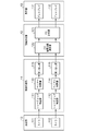
以下、本発明の第1の実施形態の詳細について図面を参照しつつ説明する。図1は、本実施形態に係る画像処理システムの構成を説明する図である。本実施形態の画像処理システムは、頭部装着型の画像表示装置、いわゆるヘッドマウントディスプレイ(以下、HMD)と、HMDと有線または無線により接続された画像処理装置とから構成されている。
[First Embodiment]
Hereinafter, the details of the first embodiment of the present invention will be described with reference to the drawings. FIG. 1 is a diagram illustrating a configuration of an image processing system according to the present embodiment. The image processing system of the present embodiment includes a head-mounted image display device, a so-called head-mounted display (hereinafter, HMD), and an image processing device connected to the HMD by wire or wirelessly.
HMDは、カメラを含み撮像画像を生成する撮像部10と、表示画像をディスプレイに表示する表示部13とから構成される。また、画像処理装置は、撮像画像に対して画像処理を行って表示画像を生成する画像処理部11と、表示画像の内容に応じて重畳する仮想物体のCGデータの位置を演算し、表示画像にCGデータを合成する画像合成部12とから構成される。
The HMD includes an
ここでは、画像処理部11および画像合成部12は、HMDとは別体の画像処理装置に備えられる構成として説明しているが、全ての機能をHMDに持たせることにより、HMD単体で動作できるようにしてもよい。HMDを頭部に装着した体験者(ユーザ)は、外界を映した画像にCGを重畳した画像をHMD内部のディスプレイを通じて観察することができ、現実と仮想世界がリアルタイムに融合した複合現実感を体感することができる。
Here, the
画像処理装置は、CPU、ROM、RAM、HDD等のハードウェア構成を備え、CPUがROMやHD等に格納されたプログラムを実行することにより、各機能構成やフローチャートの処理が実現される。RAMは、CPUがプログラムを展開して実行するワークエリアとして機能する記憶領域を有する。ROMは、CPUが実行するプログラム等を格納する記憶領域を有する。HDDは、CPUが処理を実行する際に要する各種のプログラム、閾値に関するデータ等を含む各種のデータを格納する記憶領域を有する。 The image processing device includes a hardware configuration such as a CPU, ROM, RAM, and HDD, and the CPU executes a program stored in the ROM, HD, or the like to realize processing of each functional configuration or flowchart. The RAM has a storage area that functions as a work area in which the CPU develops and executes a program. The ROM has a storage area for storing a program or the like executed by the CPU. The HDD has a storage area for storing various data including various programs required for the CPU to execute processing, data related to a threshold value, and the like.
撮像部10は、CCDやCMOS等の撮像素子と撮像光学系で構成されるカメラ101、102を含み、一定の周期でフレームごとに現実空間における被写体を撮影する。カメラ101は体験者の左眼に対応して現実空間の画像を撮影し、カメラ102は体験者の左眼に対応して現実空間の画像を撮影する。本実施形態のHMDは、視差のある画像を撮像する方法として平行法を用いる。詳細は後述するが、平行法を用いる場合、カメラ101および102は、互いの光軸間を所定距離(基線長)だけ離した状態で、光軸が互いに平行になるように配置される。
The
画像処理部11は、シェーディング補正部111、112と、ベイヤー補間部113、114と、切り出し部115、116により構成される。シェーディング補正部111、112は、後述する光量分布となるように、カメラ101、102により撮像された撮像画像に対して画角位置に応じたゲインをかけて、撮像光学系の周辺減光を補正するシェーディング補正処理を行う。ベイヤー補間部113、114は、撮像素子から出力されるベイヤー配列のベイヤーデータからRGB信号を生成するベイヤー補間処理を行う。切り出し部115、116は、撮像画像から後述する輻輳距離に応じた位置とサイズで切り出して立体視可能な表示画像を生成する切り出し処理を行う。
The
なお、本実施形態において、切り出し処理は、ベイヤー補間処理より後に行うと説明しているが、これに限るものではない。例えば、シェーディング補正処理より前に行ってもよいし、後述するCG合成処理より後に行ってもよい。また、切り出し処理は複数回に分けて行ってもよく、例えば、シェーディング補正処理の前に第1の切り出しサイズに切り出し、ベイヤー補間処理の後に第2の切り出しサイズに切り出し処理を行ってもよい。このとき、第1の切り出しサイズは第2の切り出しサイズよりも大きくなる。 In the present embodiment, it is explained that the cutting process is performed after the Bayer interpolation process, but the present invention is not limited to this. For example, it may be performed before the shading correction process or after the CG synthesis process described later. Further, the cutting process may be performed in a plurality of times. For example, the cutting process may be performed to the first cutting size before the shading correction processing, and may be performed to the second cutting size after the Bayer interpolation processing. At this time, the first cutout size is larger than the second cutout size.
画像合成部12は、CG描画位置演算部122と、CG合成部123により構成され、CG描画位置演算部122は、入力される複数の撮像映像内を画像解析し、HMD(すなわち撮像部)の位置姿勢を推定するとともに、CGの描画位置を算出する演算を行う。また、CG合成部123は、CG描画位置演算部122で求められた描画位置情報に基づき撮像画像に対してCG描画を行う。
The
表示部13は、画像合成部12によってCGが合成された合成画像を、液晶ディスプレイや有機ELディスプレイなどの表示パネルを用いたディスプレイ131と132に表示する。このようして、HMDは、2つのカメラ101、102で撮像された視差のある2つの撮像画像にCGを合成し、それら合成画像をユーザの左眼および右眼に対応するディスプレイ131、132に表示する。これにより、ユーザは立体視および複合現実感の体験が可能となる。
The
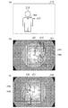
図2と図3を用いて、本実施形態における撮像部10のカメラ101、102の配置と、立体視のための視差をもった表示画像の切り出し位置およびサイズについて詳細に説明する。図2は、本実施形態における撮像部10の幾何学的配置を模式的に表した図である。図3は、本実施形態における被写体と撮像画像、表示画像の関係を表す図である。
With reference to FIGS. 2 and 3, the arrangement of the
本実施形態のカメラ101、102は、撮像素子203、204と撮像光学系201、202で構成される。なお、ここではHMDを上面から見た場合の配置についてのみ説明し、高さ方向について説明は簡略化のために省略する。本実施形態では、視差のある画像を撮像する方法として平行法を用いるため、図2の通り、撮像光学系201、202の光軸207、208は平行となるように配置される。各撮像光学系の主点205、206を結んだ線の中間位置から被写体210側に伸ばした中間線222が被写体210と交わる点を輻輳点209といい、中間位置と輻輳点209までの距離を輻輳距離211という。
The
本実施形態のHMDにおいては、基線長を63mm、輻輳距離を1.4mと設定する。輻輳点209を決定し、輻輳点209の位置に被写体があるとき、もっとも立体視が自然にできるようHMDが設計される。本実施形態では、カメラ101、102と被写体210との距離が前記輻輳距離であるとき、撮像素子203、204で撮像可能な範囲213、214が重なる領域内に、輻輳点209を中心とした立体視可能な立体視領域215を設定する。
In the HMD of the present embodiment, the baseline length is set to 63 mm and the convergence distance is set to 1.4 m. The HMD is designed so that when the
本実施形態において、撮像光学系201、202は、それぞれ撮像素子203、204の有効画像領域の中心が光軸と一致し、かつ有効画像領域220、221いっぱいに被写体の像を結像し、撮像画像を出力する。切り出し部115、116では、撮像素子203、204に結像される撮像画像において、輻輳点209と主点205、206とをそれぞれ結ぶ線と撮像素子が交わる点216、217を立体視領域の中心として切り出し処理を行う。また、立体視領域は、撮像素子203、204上において結像される範囲218、219となり、切り出し部115、116は、撮像画像から範囲218、219を表示画像として切り出す。すなわち、本実施形態では、撮像光学系の中心とは異なる位置を中心とした範囲を切り出し範囲として切り出すようにしている。
In the present embodiment, in the imaging
図3(a)は、範囲213において、カメラ101から輻輳距離211離れた被写体210と、カメラ101の光軸207、および輻輳点209との関係を示す。また、図3(b)は、図3(a)の被写体210が撮像素子203に結像される像301、光軸207、立体視領域218、およびその中心216の関係を示す。撮像素子203に結像される像は倒立の像となるため、被写体210は光軸207を中心として点対象に見える。また、撮像光学系201の光学特性により周辺減光が発生している。図3(b)に示すように、本実施形態における周辺減光は、光軸207を中心として、光軸207から離れるにつれて減光量が連続的に増加する。
FIG. 3A shows the relationship between the subject 210, which is a
図3(c)は、撮像素子203から出力される撮像画像220と立体視領域218およびその中心216との関係を示す。撮像素子203から出力される撮像画像220は、正立の像となるよう回転して出力される。図3(c)に示すように、表示画像として切り出す立体視領域218は、撮像画像220に対して光軸207より輻輳距離に応じた分だけ中間線222に寄った領域となることがわかる。なお、もう一方のカメラ102の場合も同様で、表示画像として切り出す立体視領域219は、光軸207より輻輳距離に応じた分だけ中間線222に寄った領域となる。このように、本実施形態では、左右の撮像画像それぞれで、撮像光学系の光軸中心とは異なる位置を中心とした範囲を切り出し範囲として切り出すようにしており、光軸に対する切り出し範囲の相対位置は左右の撮像画像において異なっている。
FIG. 3C shows the relationship between the captured
図4は、本実施形態において撮像光学系および撮像画像の光量分布を説明する図であり、図5は、本実施形態に係るシェーディング補正を説明する図である。図4において、401は撮像光学系201の周辺光量を示しており、402は本実施形態のシェーディング補正処理によって補正された光量分布を示している。図に示す周辺光量401の通り、本実施形態の撮像光学系201は、光軸207の位置で光量が100%となり、周辺に向かって徐々に減光し、端部では20%程度まで光量が落ちているのがわかる。
FIG. 4 is a diagram for explaining the light amount distribution of the imaging optical system and the captured image in the present embodiment, and FIG. 5 is a diagram for explaining the shading correction according to the present embodiment. In FIG. 4, 401 shows the peripheral light amount of the imaging
図5において、501は周辺光量401を全画角位置で均一となるようにシェーディング補正する場合の画角位置に応じた画素毎のゲインを示している。また、502は本実施形態のシェーディング補正処理で用いる画角位置に応じた画素毎のゲインを示している。図に示すゲイン501の通り、従来手法のシェーディング補正では、光軸207の画角位置では100%のゲインとなるが、周辺に向かって徐々にゲインが大きくなり、最大で500%ものゲインが必要になる。この場合、撮像画像に含まれるノイズ成分も同じだけ増幅されるため、光軸207付近に比べて撮像画像周辺は非常にノイズの多い画像となってしまう。
In FIG. 5, 501 shows the gain for each pixel according to the angle of view position when shading correction is performed so that the
一方、本実施形態のシェーディング補正では、光量分布402のように、立体視領域の中心216を中心とし、光軸207までを半径とした範囲を100%の光量となるように補正している。そのため、本実施形態のシェーディング補正は、従来手法に比べてノイズの発生を抑制することができる。
On the other hand, in the shading correction of the present embodiment, as in the
また、立体視領域の中心216を中心として、その範囲を超える画角に対しては、周辺に向かって徐々に減光させ、光量が100%未満となるように補正する。ゲイン502のように、立体視領域の中心216に対して光軸207までを半径とした範囲では、全画角位置で100%に補正するゲイン501と同様のゲインとなる。また、前記範囲を超える画角に対しては、ゲイン501と比較して、周辺に向かって徐々にゲインが低下しているのがわかる。
Further, with the
なお、本実施形態では、ゲイン502は、撮像画像の明るさを損なわないために、全画角位置において、100%のゲインを下回らないよう設計されている(すなわち、1倍以上のゲインをかけるようにしている)。また、ここまでカメラ101の場合を説明してきたが、もう一方のカメラ102の場合も同様で、立体視領域の中心217を中心とし、光軸208までを半径とした範囲で光量が100%となるようシェーディング補正処理が行われる。このように、本実施形態では、左右の表示画像(切り出し範囲)それぞれで、立体視領域の中心位置を中心としたシェーディング補正処理が実行される。
In the present embodiment, the
図6は、本実施形態におけるシェーディング補正処理を行った後の被写体と撮像画像、表示画像の関係を表す図である。撮像画像601は、撮像画像220に対して、ゲイン502を用いてシェーディング補正処理を行ったものである。図6に示すように、立体視領域の中心216が中心となるように周辺減光がシェーディング補正処理によって補正され、また、立体視領域の中心216から撮像画像601の外側の周辺に向かって徐々に周辺光量が抑えられていることがわかる。
FIG. 6 is a diagram showing the relationship between the subject, the captured image, and the displayed image after the shading correction processing in the present embodiment is performed. The captured
本実施形態の画像処理装置では、撮像画像601から切り出し処理によって立体視領域218が右眼用の表示画像として切り出され、CGが描画される。その処理の後、CGが描画された合成画像がHMDに送られ、ディスプレイ131に表示される。
In the image processing apparatus of the present embodiment, the
なお、本実施形態のシェーディング補正処理に用いるゲインは、画角位置に応じて画素毎にゲイン値を持つと説明したが、これに限るものではない。例えば、所定数の画素おきに離散的なゲイン値を持ち、ゲイン値を持たない画素位置においては、その周囲のゲイン値から補間処理を行うことによってゲイン値を求めるなどしてもよい。 Although it has been explained that the gain used for the shading correction processing of the present embodiment has a gain value for each pixel according to the angle of view position, the gain is not limited to this. For example, at a pixel position that has discrete gain values every predetermined number of pixels and does not have a gain value, the gain value may be obtained by performing interpolation processing from the surrounding gain values.
図12には、本実施形態に係る画像処理装置による画像処理の詳細を示すフローチャートである。ステップS1201において、画像処理部11は、画像処理装置のI/Fを介してHMDの撮像部10(カメラ101、102)により撮像された撮像画像を取得する。次に、ステップS1201において、シェーディング補正部111、112は撮像された撮像画像に対して画角位置に応じたゲインをかけて、撮像光学系の周辺減光を補正するシェーディング補正処理を行う。本実施形態においては、前述のとおり、立体視領域の中心216を中心としたシェーディング補正を実行する。
FIG. 12 is a flowchart showing details of image processing by the image processing apparatus according to the present embodiment. In step S1201, the
ステップS1203において、ベイヤー補間部113、114はベイヤー補間処理を行う。次に、ステップS1204において、切り出し部115、116は、撮像画像から立体視可能な表示画像を生成する切り出し処理を行う。本実施形態の切り出し処理は、前述のとおり、撮像光学系の中心とは異なる位置を中心とした範囲を切り出し範囲(表示画像)として切り出す。
In step S1203, the
ステップS1205において、HMD(すなわち撮像部)の位置姿勢を推定し、CGの描画位置を算出する。次に、ステップS1206において、CG合成部123は、算出した描画位置に基づいて撮像画像に対してCG描画を行い、合成画像を生成する。ステップS1207において、画像合成部12は、画像処理装置のI/Fを介して、HMDに生成した合成を出力する。
In step S1205, the position and orientation of the HMD (that is, the imaging unit) are estimated, and the drawing position of the CG is calculated. Next, in step S1206, the
以上説明したように、本実施形態によれば、シェーディング補正処理によって、左右2つの撮像部により撮像された撮像画像から生成された(切り出された)表示画像の光量分布がほぼ一致するため、自然な立体視を実現することができる。 As described above, according to the present embodiment, the light intensity distributions of the display images generated (cut out) from the captured images captured by the two left and right imaging units by the shading correction process are substantially the same, so that it is natural. A solid stereoscopic view can be realized.
[第2の実施形態]
次に、本発明の第2の実施形態について説明する。第1の実施形態では、輻輳距離に応じて設定される立体視領域を切り出して、視差のある左右の表示画像とし、ディスプレイ131、132に表示することにより、立体視および複合現実感の体験が可能となる構成を説明した。本実施形態においては、表示視野角を大きくするために、撮像画像から立体視不可能な平面視領域も含む領域を表示画像として切り出して表示する。なお、第1の実施形態において既に説明をした構成については同一の符号を付し、その説明は省略する。
[Second Embodiment]
Next, a second embodiment of the present invention will be described. In the first embodiment, the stereoscopic area set according to the congestion distance is cut out to be left and right display images with parallax, and the images are displayed on the
図7は、本実施形態における撮像部10の幾何学的配置を模式的に表した図である。本実施形態では、第1の実施形態で説明したように、輻輳距離211であるとき、撮像素子203、204で撮像可能な範囲213、214が重なる領域内に、輻輳点209を中心とした立体視領域215を設定する。さらに、立体視領域215と連続し、中間線222から離れる方向に、立体視不可能な平面視領域701、702を設定する。本実施形態における平面視領域とは、輻輳距離だけ離れた被写体において、一方のカメラにのみ映る領域である。撮像素子203、204に結像される撮像画像において、立体視領域は218、219、平面視領域は703、704となる。本実施形態の切り出し部115、116は、撮像画像から立体視領域と平面視領域を含む範囲705、706を表示画像として切り出す。
FIG. 7 is a diagram schematically showing the geometrical arrangement of the
図8は、本実施形態における撮像画像、表示画像の関係を表す図である。図8には、撮像素子203から出力される撮像画像220と立体視領域218とその中心216、平面視領域703、表示画像705の関係を示す。撮像素子203から出力される撮像画像220は、正立の像となる。図8に示すように、表示画像として切り出す領域705は、立体視領域218と、平面視領域703とから成る。立体視領域218は、撮像画像220に対して、光軸207より輻輳距離に応じた分だけ中間線222に寄った領域である。また、平面視領域703は、中間線222から離れる方向に、立体視領域218と連続した領域となることがわかる。なお、もう一方のカメラ102の場合も同様で、表示画像として切り出す立体視領域219は、光軸207より輻輳距離に応じた分だけ中間線222に寄った領域となる。また、平面視領域706は中間線222から離れる方向に、立体視領域219と連続した領域となる。
FIG. 8 is a diagram showing the relationship between the captured image and the displayed image in the present embodiment. FIG. 8 shows the relationship between the captured
次に、図9、図10、図11を用いて、本実施形態におけるシェーディング補正部111、112で行われるシェーディング補正処理について詳細に説明する。図9は、本実施形態における撮像光学系の周辺光量と、本実施形態のシェーディング補正処理によって補正された撮像画像の光量分布を示す図である。図10は、本実施形態のシェーディング補正処理によって用いられるゲインを示す図である。なお、ここでは説明を簡単にするために、撮像画像の光軸および立体視領域の中心を通る水平位置でスライスした場合を例に説明する。
Next, the shading correction processing performed by the
本実施形態においても、第1の実施形態と同様に、光量分布402となるように、すなわち、立体視領域の中心216を中心とし、光軸207までを半径とした範囲を100%の光量となるように補正を行う。また、立体視領域の中心216を中心として、上述の範囲を超える画角に対しては、平面視領域703も含み、周辺に向かって徐々に減光させ、光量が100%未満となるように補正する。図に示すように、ゲイン502は、立体視領域の中心216を中心とし、光軸207までを半径とした範囲では、全画角位置で100%に補正するゲイン501と同様のゲインとなる。また、上述の範囲を超える画角に対しては、平面視領域703も含み、周辺に向かって徐々にゲインが低下していることがわかる。また、表示画像として切り出す領域705において、シェーディング補正処理後の光量分布をある位置でスライスした場合に、平面視領域の光量は立体視領域よりも低くなるように補正される。
Also in the present embodiment, as in the first embodiment, the light amount is 100% so that the light amount distribution is 402, that is, the range centered on the
なお、本実施形態において、ゲイン502は、撮像画像の明るさを損なわないために、全画角位置において、100%のゲインを下回らないよう設計される。なお、ここまでカメラ101について説明してきたが、もう一方のカメラ102も同様で、立体視領域の中心217を中心として、光軸208までを半径とした範囲で光量が100%となるようシェーディング補正処理が行われる。
In the present embodiment, the
図11は、本実施形態におけるシェーディング補正処理を行った後の被写体と撮像画像、表示画像の関係を表す図である。撮像画像1101は、撮像画像220に対して、ゲイン502を用いてシェーディング補正処理を行ったものである。図11に示すように、立体視領域の中心216が中心となるように周辺減光がシェーディング補正処理によって補正され、また、立体視領域の中心216から撮像画像1101の周辺に向かって徐々に周辺光量が抑えられていることがわかる。本実施形態の画像処理装置では、撮像画像1101から切り出し処理によって立体視領域218と平面視領域703を含む領域705が右眼用の表示画像として切り出され、その表示画像にCGが描画された合成画像を生成する。そして、生成された合成画像はHMDに送られ、HMDのディスプレイ131に表示される。
FIG. 11 is a diagram showing the relationship between the subject, the captured image, and the displayed image after the shading correction processing in the present embodiment is performed. The captured
なお、本実施形態のシェーディング補正処理に用いるゲインは、画角位置に応じて画素毎にゲイン値を持つと説明したが、これに限るものではない。第1の実施形態で説明したように、例えば、数画素おきに離散的なゲイン値を持ち、ゲイン値を持たない画素位置においては、その周囲のゲイン値から補間処理を行うことによってゲイン値を求めるなどしてもよい。 Although it has been explained that the gain used for the shading correction processing of the present embodiment has a gain value for each pixel according to the angle of view position, the gain is not limited to this. As described in the first embodiment, for example, at a pixel position having discrete gain values every few pixels and having no gain value, the gain value is calculated by performing interpolation processing from the surrounding gain values. You may ask for it.
以上説明したように、本実施形態によれば、シェーディング補正処理によって、過度にノイズを増幅することなく、左右の立体視可能な立体視領域の光量分布がほぼ一致するため、自然な立体視を実現することができる。 As described above, according to the present embodiment, the shading correction processing substantially matches the light amount distributions of the left and right stereoscopic viewing regions without excessively amplifying noise, so that natural stereoscopic vision can be achieved. It can be realized.
[その他の実施形態]
また、本発明は、実施形態の機能を実現するソフトウェア(プログラム)を、ネットワーク又は各種記憶媒体を介してシステム或いは装置に供給し、そのシステム或いは装置のコンピュータ(又はCPUやMPU等)がプログラムを読み出して実行する処理である。また、1以上の機能を実現する回路(例えば、ASIC)によっても実現可能である。また、本発明は、複数の機器から構成されるシステムに適用しても、1つの機器からなる装置に適用してもよい。本発明は上記実施形態に限定されるものではなく、本発明の趣旨に基づき種々の変形(各実施形態の有機的な組合せを含む)が可能であり、それらを本発明の範囲から除外するものではない。即ち、上述した各実施形態及びその変形例を組み合わせた構成も全て本発明に含まれるものである。
[Other Embodiments]
Further, in the present invention, software (program) that realizes the functions of the embodiment is supplied to a system or device via a network or various storage media, and a computer (or CPU, MPU, etc.) of the system or device executes the program. This is a process to read and execute. It can also be realized by a circuit (for example, ASIC) that realizes one or more functions. Further, the present invention may be applied to a system composed of a plurality of devices or a device composed of one device. The present invention is not limited to the above embodiments, and various modifications (including organic combinations of each embodiment) are possible based on the gist of the present invention, and these are excluded from the scope of the present invention. is not it. That is, all the configurations in which each of the above-described embodiments and modifications thereof are combined are also included in the present invention.
10 撮像部
11 画像処理部
12 画像合成部
13 表示部
10
Claims (17)
前記第1の撮像画像および第2の撮像画像から、それぞれの前記光軸に対する相対位置が異なる領域を第1の表示画像および第2の表示画像として切り出す切り出し手段と、
前記切り出された第1の表示画像および第2の表示画像と仮想物体とを合成して第1の合成画像および第2の合成画像を生成する生成手段と、を有し、
前記切り出し手段は、前記第1の表示画像および第2の表示画像それぞれにユーザが被写体を立体視する立体視領域を含むように前記第1の表示画像および第2の表示画像を切り出し、
前記補正手段は、前記第1の表示画像および第2の表示画像それぞれの前記立体視領域の中心の位置を中心として前記シェーディング補正を行うことを特徴とする画像処理装置。 Shading correction for the first captured image and the second captured image captured by the first imaging unit and the second imaging unit, which have different optical axes and correspond to the user's left eye and right eye. And the correction means to do
A cutting means for cutting out a region having a different relative position with respect to the optical axis from the first captured image and the second captured image as a first display image and a second display image.
It has a generation means for generating a first composite image and a second composite image by synthesizing the cut-out first display image, the second display image, and a virtual object.
The cutting means cuts out the first display image and the second display image so that each of the first display image and the second display image includes a stereoscopic viewing region in which the user stereoscopically views the subject.
The correction means is an image processing apparatus characterized in that the shading correction is performed centering on the position of the center of the stereoscopic region of each of the first display image and the second display image.
前記第1の撮像部および第2の撮像部によって撮像された第1の撮像画像と第2の撮像画像に対してシェーディング補正を行う補正手段と、
前記第1の撮像画像および第2の撮像画像から、それぞれの前記光軸に対する相対位置が異なる領域を第1の表示画像および第2の表示画像として切り出す切り出し手段と、
前記切り出された第1の表示画像および第2の表示画像と仮想物体とを合成して第1の合成画像および第2の合成画像を生成する生成手段と、を有し、
前記切り出し手段は、前記第1の表示画像および第2の表示画像それぞれにユーザが被写体を立体視する立体視領域を含むように前記第1の表示画像および第2の表示画像を切り出し、
前記補正手段は、前記第1の表示画像および第2の表示画像それぞれの前記立体視領域の中心の位置を中心として前記シェーディング補正を行うことを特徴とする画像処理システム。 A first imaging unit and a second imaging unit, each having a different optical axis and corresponding to the user's left eye and right eye,
A correction means for performing shading correction on the first captured image and the second captured image captured by the first imaging unit and the second imaging unit, and
A cutting means for cutting out a region having a different relative position with respect to the optical axis from the first captured image and the second captured image as a first display image and a second display image.
It has a generation means for generating a first composite image and a second composite image by synthesizing the cut-out first display image, the second display image, and a virtual object.
The cutting means cuts out the first display image and the second display image so that each of the first display image and the second display image includes a stereoscopic viewing region in which the user stereoscopically views the subject.
The correction means is an image processing system characterized in that the shading correction is performed centering on the position of the center of the stereoscopic visual region of each of the first display image and the second display image.
前記第1の撮像画像および第2の撮像画像から、それぞれの前記光軸に対する相対位置が異なる領域を第1の表示画像および第2の表示画像として切り出すステップと、
前記切り出された第1の表示画像および第2の表示画像と仮想物体とを合成して第1の合成画像および第2の合成画像を生成するステップと、を有し、
前記切り出すステップでは、前記第1の表示画像および第2の表示画像それぞれにユーザが被写体を立体視する立体視領域を含むように前記第1の表示画像および第2の表示画像を切り出し、
前記補正するステップでは、前記第1の表示画像および第2の表示画像それぞれの前記立体視領域の中心の位置を中心として前記シェーディング補正を行うことを特徴とする画像処理方法。 Shading correction for the first captured image and the second captured image captured by the first imaging unit and the second imaging unit, which have different optical axes and correspond to the user's left eye and right eye. And the steps to do
A step of cutting out a region having a different relative position with respect to the optical axis from the first captured image and the second captured image as a first display image and a second display image.
It has a step of synthesizing the cut-out first display image, the second display image, and a virtual object to generate a first composite image and a second composite image.
In the cutout step, the first display image and the second display image are cut out so that each of the first display image and the second display image includes a stereoscopic viewing region in which the user stereoscopically views the subject.
The image processing method, characterized in that, in the correction step, the shading correction is performed centering on the position of the center of the stereoscopic visual region of each of the first display image and the second display image.
Priority Applications (2)
| Application Number | Priority Date | Filing Date | Title |
|---|---|---|---|
| JP2017027294A JP6862210B2 (en) | 2017-02-16 | 2017-02-16 | Image processing equipment, image processing system, image processing method and program |
| US15/892,303 US10438402B2 (en) | 2017-02-16 | 2018-02-08 | Image processing apparatus, image processing system, image processing method, and storage medium |
Applications Claiming Priority (1)
| Application Number | Priority Date | Filing Date | Title |
|---|---|---|---|
| JP2017027294A JP6862210B2 (en) | 2017-02-16 | 2017-02-16 | Image processing equipment, image processing system, image processing method and program |
Publications (3)
| Publication Number | Publication Date |
|---|---|
| JP2018133746A JP2018133746A (en) | 2018-08-23 |
| JP2018133746A5 JP2018133746A5 (en) | 2020-02-06 |
| JP6862210B2 true JP6862210B2 (en) | 2021-04-21 |
Family
ID=63104739
Family Applications (1)
| Application Number | Title | Priority Date | Filing Date |
|---|---|---|---|
| JP2017027294A Active JP6862210B2 (en) | 2017-02-16 | 2017-02-16 | Image processing equipment, image processing system, image processing method and program |
Country Status (2)
| Country | Link |
|---|---|
| US (1) | US10438402B2 (en) |
| JP (1) | JP6862210B2 (en) |
Families Citing this family (4)
| Publication number | Priority date | Publication date | Assignee | Title |
|---|---|---|---|---|
| WO2020069460A1 (en) | 2018-09-28 | 2020-04-02 | Bounce Imaging, Inc. | Panoramic camera and image processing systems and methods |
| CN113557717A (en) | 2019-03-19 | 2021-10-26 | 索尼集团公司 | Information processing apparatus, information processing method, and program |
| US11137607B2 (en) * | 2019-06-28 | 2021-10-05 | Canon Kabushiki Kaisha | Image capturing and display apparatus and wearable device |
| JP2021039444A (en) * | 2019-08-30 | 2021-03-11 | キヤノン株式会社 | Image processing device, control method and program thereof |
Family Cites Families (12)
| Publication number | Priority date | Publication date | Assignee | Title |
|---|---|---|---|---|
| JP4442624B2 (en) * | 2006-06-22 | 2010-03-31 | 株式会社デンソーウェーブ | Optical information reader |
| JP5317562B2 (en) * | 2008-07-17 | 2013-10-16 | キヤノン株式会社 | Phase difference detection device, imaging device, phase difference detection method, phase difference detection program |
| WO2011121841A1 (en) * | 2010-03-31 | 2011-10-06 | 富士フイルム株式会社 | 3d-image capturing device |
| JP5567901B2 (en) * | 2010-05-24 | 2014-08-06 | オリンパスイメージング株式会社 | Interchangeable lens and imaging system for stereo photography |
| US8336539B2 (en) * | 2010-08-03 | 2012-12-25 | Sunpower Corporation | Opposing row linear concentrator architecture |
| US8803764B2 (en) * | 2011-03-24 | 2014-08-12 | Seiko Epson Corporation | Head-mount type display device and method of controlling head-mount type display device |
| JP5444505B2 (en) * | 2011-05-03 | 2014-03-19 | オリンパスイメージング株式会社 | Stereoscopic image processing apparatus and stereoscopic image processing method |
| JP5765070B2 (en) * | 2011-06-13 | 2015-08-19 | ソニー株式会社 | Display switching device, display switching method, display switching program |
| US8873112B2 (en) * | 2011-10-21 | 2014-10-28 | Canon Kabushiki Kaisha | Image processing apparatus and determination method |
| TWI649675B (en) * | 2013-03-28 | 2019-02-01 | 新力股份有限公司 | Display device |
| CN105122793B (en) * | 2013-03-29 | 2017-05-10 | 株式会社尼康 | Image processing device, image capture device, and image processing program |
| KR102401582B1 (en) * | 2015-09-24 | 2022-05-24 | 삼성전자주식회사 | Lens shading correction circuit and apparatus having the same |
-
2017
- 2017-02-16 JP JP2017027294A patent/JP6862210B2/en active Active
-
2018
- 2018-02-08 US US15/892,303 patent/US10438402B2/en active Active
Also Published As
| Publication number | Publication date |
|---|---|
| US10438402B2 (en) | 2019-10-08 |
| JP2018133746A (en) | 2018-08-23 |
| US20180232945A1 (en) | 2018-08-16 |
Similar Documents
| Publication | Publication Date | Title |
|---|---|---|
| US9191658B2 (en) | Head-mounted display and position gap adjustment method | |
| JP4875762B2 (en) | Image processing apparatus, image display apparatus, and image pickup apparatus | |
| JP6862210B2 (en) | Image processing equipment, image processing system, image processing method and program | |
| JP5355208B2 (en) | Three-dimensional display device and digital zoom correction method | |
| WO2017138458A1 (en) | Video display system | |
| US10547832B2 (en) | Image processing apparatus, method, and storage medium for executing gradation on stereoscopic images | |
| JP7358448B2 (en) | Image generation device, head mounted display, and image generation method | |
| US7940295B2 (en) | Image display apparatus and control method thereof | |
| US20230239457A1 (en) | System and method for corrected video-see-through for head mounted displays | |
| JP5820985B2 (en) | Stereoscopic image processing apparatus and stereoscopic image processing method | |
| JP6253030B2 (en) | Image processing apparatus, imaging apparatus, and image processing method | |
| WO2020115815A1 (en) | Head-mounted display device | |
| WO2019131160A1 (en) | Information processing device, information processing method, and recording medium | |
| JP2018133746A5 (en) | ||
| JP5645255B2 (en) | Image processing apparatus and image processing method | |
| TW201733351A (en) | Three-dimensional auto-focusing method and the system thereof | |
| JPWO2018189880A1 (en) | Information processing apparatus, information processing system, and image processing method | |
| JP6887824B2 (en) | Image processing equipment, image processing methods and programs | |
| JP7365184B2 (en) | Image processing device, head-mounted display, and image display method | |
| JP7429515B2 (en) | Image processing device, head-mounted display, and image display method | |
| JP2017215688A (en) | Image processor and image processing method | |
| JP6932526B2 (en) | Image display device, image display method and program | |
| JP7066414B2 (en) | Image processing equipment, display system, image processing method and program | |
| JPWO2019082415A1 (en) | Image processing device, imaging device, control method of image processing device, image processing program and recording medium | |
| JP6930011B2 (en) | Information processing equipment, information processing system, and image processing method |
Legal Events
| Date | Code | Title | Description |
|---|---|---|---|
| A521 | Request for written amendment filed |
Free format text: JAPANESE INTERMEDIATE CODE: A523 Effective date: 20191220 |
|
| A621 | Written request for application examination |
Free format text: JAPANESE INTERMEDIATE CODE: A621 Effective date: 20191220 |
|
| A977 | Report on retrieval |
Free format text: JAPANESE INTERMEDIATE CODE: A971007 Effective date: 20200918 |
|
| A131 | Notification of reasons for refusal |
Free format text: JAPANESE INTERMEDIATE CODE: A131 Effective date: 20200929 |
|
| A521 | Request for written amendment filed |
Free format text: JAPANESE INTERMEDIATE CODE: A523 Effective date: 20201120 |
|
| TRDD | Decision of grant or rejection written | ||
| A01 | Written decision to grant a patent or to grant a registration (utility model) |
Free format text: JAPANESE INTERMEDIATE CODE: A01 Effective date: 20210302 |
|
| A61 | First payment of annual fees (during grant procedure) |
Free format text: JAPANESE INTERMEDIATE CODE: A61 Effective date: 20210331 |
|
| R151 | Written notification of patent or utility model registration |
Ref document number: 6862210 Country of ref document: JP Free format text: JAPANESE INTERMEDIATE CODE: R151 |