JP6858717B2 - Dynamic holography Depth of focus printing device - Google Patents
Dynamic holography Depth of focus printing device Download PDFInfo
- Publication number
- JP6858717B2 JP6858717B2 JP2017566644A JP2017566644A JP6858717B2 JP 6858717 B2 JP6858717 B2 JP 6858717B2 JP 2017566644 A JP2017566644 A JP 2017566644A JP 2017566644 A JP2017566644 A JP 2017566644A JP 6858717 B2 JP6858717 B2 JP 6858717B2
- Authority
- JP
- Japan
- Prior art keywords
- lcos
- slm
- control signal
- holographic
- target material
- Prior art date
- Legal status (The legal status is an assumption and is not a legal conclusion. Google has not performed a legal analysis and makes no representation as to the accuracy of the status listed.)
- Active
Links
- 238000007639 printing Methods 0.000 title claims description 97
- 238000001093 holography Methods 0.000 title description 41
- 238000000034 method Methods 0.000 claims description 49
- 239000013077 target material Substances 0.000 claims description 40
- 230000005855 radiation Effects 0.000 claims 1
- 230000003287 optical effect Effects 0.000 description 25
- 230000015654 memory Effects 0.000 description 21
- 239000004973 liquid crystal related substance Substances 0.000 description 18
- 239000002609 medium Substances 0.000 description 16
- 238000010586 diagram Methods 0.000 description 15
- 230000006870 function Effects 0.000 description 14
- 238000010438 heat treatment Methods 0.000 description 11
- 238000010146 3D printing Methods 0.000 description 10
- XUIMIQQOPSSXEZ-UHFFFAOYSA-N Silicon Chemical compound [Si] XUIMIQQOPSSXEZ-UHFFFAOYSA-N 0.000 description 10
- 229910052710 silicon Inorganic materials 0.000 description 10
- 239000010703 silicon Substances 0.000 description 10
- 238000001723 curing Methods 0.000 description 9
- 230000008569 process Effects 0.000 description 8
- 230000001052 transient effect Effects 0.000 description 8
- 239000000463 material Substances 0.000 description 7
- 239000000758 substrate Substances 0.000 description 7
- 238000004891 communication Methods 0.000 description 6
- 230000001066 destructive effect Effects 0.000 description 5
- 230000005540 biological transmission Effects 0.000 description 4
- 230000000694 effects Effects 0.000 description 4
- 238000012545 processing Methods 0.000 description 4
- 230000008901 benefit Effects 0.000 description 3
- 238000001514 detection method Methods 0.000 description 3
- 238000009826 distribution Methods 0.000 description 3
- 230000001678 irradiating effect Effects 0.000 description 3
- 230000004044 response Effects 0.000 description 3
- 230000003595 spectral effect Effects 0.000 description 3
- 230000000007 visual effect Effects 0.000 description 3
- 238000013500 data storage Methods 0.000 description 2
- 238000005516 engineering process Methods 0.000 description 2
- 238000012986 modification Methods 0.000 description 2
- 230000004048 modification Effects 0.000 description 2
- 238000005245 sintering Methods 0.000 description 2
- 230000009466 transformation Effects 0.000 description 2
- 239000006163 transport media Substances 0.000 description 2
- 230000001133 acceleration Effects 0.000 description 1
- 230000009471 action Effects 0.000 description 1
- 238000007792 addition Methods 0.000 description 1
- XAGFODPZIPBFFR-UHFFFAOYSA-N aluminium Chemical compound [Al] XAGFODPZIPBFFR-UHFFFAOYSA-N 0.000 description 1
- 229910052782 aluminium Inorganic materials 0.000 description 1
- 238000013459 approach Methods 0.000 description 1
- 230000006399 behavior Effects 0.000 description 1
- 230000036772 blood pressure Effects 0.000 description 1
- 230000008859 change Effects 0.000 description 1
- 238000006243 chemical reaction Methods 0.000 description 1
- 230000001427 coherent effect Effects 0.000 description 1
- 230000003750 conditioning effect Effects 0.000 description 1
- 230000008878 coupling Effects 0.000 description 1
- 238000010168 coupling process Methods 0.000 description 1
- 238000005859 coupling reaction Methods 0.000 description 1
- 239000013078 crystal Substances 0.000 description 1
- 230000001934 delay Effects 0.000 description 1
- 239000011521 glass Substances 0.000 description 1
- 238000013007 heat curing Methods 0.000 description 1
- 230000006872 improvement Effects 0.000 description 1
- 238000012804 iterative process Methods 0.000 description 1
- 238000001459 lithography Methods 0.000 description 1
- 239000002243 precursor Substances 0.000 description 1
- 230000001902 propagating effect Effects 0.000 description 1
- 230000008054 signal transmission Effects 0.000 description 1
- 238000007711 solidification Methods 0.000 description 1
- 230000008023 solidification Effects 0.000 description 1
- 238000001228 spectrum Methods 0.000 description 1
- 230000003068 static effect Effects 0.000 description 1
- 230000002194 synthesizing effect Effects 0.000 description 1
- 238000012546 transfer Methods 0.000 description 1
- 238000000844 transformation Methods 0.000 description 1
Images


Classifications
-
- B—PERFORMING OPERATIONS; TRANSPORTING
- B29—WORKING OF PLASTICS; WORKING OF SUBSTANCES IN A PLASTIC STATE IN GENERAL
- B29C—SHAPING OR JOINING OF PLASTICS; SHAPING OF MATERIAL IN A PLASTIC STATE, NOT OTHERWISE PROVIDED FOR; AFTER-TREATMENT OF THE SHAPED PRODUCTS, e.g. REPAIRING
- B29C64/00—Additive manufacturing, i.e. manufacturing of three-dimensional [3D] objects by additive deposition, additive agglomeration or additive layering, e.g. by 3D printing, stereolithography or selective laser sintering
- B29C64/10—Processes of additive manufacturing
- B29C64/106—Processes of additive manufacturing using only liquids or viscous materials, e.g. depositing a continuous bead of viscous material
-
- B—PERFORMING OPERATIONS; TRANSPORTING
- B29—WORKING OF PLASTICS; WORKING OF SUBSTANCES IN A PLASTIC STATE IN GENERAL
- B29C—SHAPING OR JOINING OF PLASTICS; SHAPING OF MATERIAL IN A PLASTIC STATE, NOT OTHERWISE PROVIDED FOR; AFTER-TREATMENT OF THE SHAPED PRODUCTS, e.g. REPAIRING
- B29C64/00—Additive manufacturing, i.e. manufacturing of three-dimensional [3D] objects by additive deposition, additive agglomeration or additive layering, e.g. by 3D printing, stereolithography or selective laser sintering
- B29C64/20—Apparatus for additive manufacturing; Details thereof or accessories therefor
- B29C64/227—Driving means
-
- B—PERFORMING OPERATIONS; TRANSPORTING
- B29—WORKING OF PLASTICS; WORKING OF SUBSTANCES IN A PLASTIC STATE IN GENERAL
- B29C—SHAPING OR JOINING OF PLASTICS; SHAPING OF MATERIAL IN A PLASTIC STATE, NOT OTHERWISE PROVIDED FOR; AFTER-TREATMENT OF THE SHAPED PRODUCTS, e.g. REPAIRING
- B29C64/00—Additive manufacturing, i.e. manufacturing of three-dimensional [3D] objects by additive deposition, additive agglomeration or additive layering, e.g. by 3D printing, stereolithography or selective laser sintering
- B29C64/20—Apparatus for additive manufacturing; Details thereof or accessories therefor
- B29C64/264—Arrangements for irradiation
- B29C64/268—Arrangements for irradiation using laser beams; using electron beams [EB]
- B29C64/273—Arrangements for irradiation using laser beams; using electron beams [EB] pulsed; frequency modulated
-
- B—PERFORMING OPERATIONS; TRANSPORTING
- B29—WORKING OF PLASTICS; WORKING OF SUBSTANCES IN A PLASTIC STATE IN GENERAL
- B29C—SHAPING OR JOINING OF PLASTICS; SHAPING OF MATERIAL IN A PLASTIC STATE, NOT OTHERWISE PROVIDED FOR; AFTER-TREATMENT OF THE SHAPED PRODUCTS, e.g. REPAIRING
- B29C64/00—Additive manufacturing, i.e. manufacturing of three-dimensional [3D] objects by additive deposition, additive agglomeration or additive layering, e.g. by 3D printing, stereolithography or selective laser sintering
- B29C64/20—Apparatus for additive manufacturing; Details thereof or accessories therefor
- B29C64/264—Arrangements for irradiation
- B29C64/277—Arrangements for irradiation using multiple radiation means, e.g. micromirrors or multiple light-emitting diodes [LED]
-
- B—PERFORMING OPERATIONS; TRANSPORTING
- B33—ADDITIVE MANUFACTURING TECHNOLOGY
- B33Y—ADDITIVE MANUFACTURING, i.e. MANUFACTURING OF THREE-DIMENSIONAL [3-D] OBJECTS BY ADDITIVE DEPOSITION, ADDITIVE AGGLOMERATION OR ADDITIVE LAYERING, e.g. BY 3-D PRINTING, STEREOLITHOGRAPHY OR SELECTIVE LASER SINTERING
- B33Y10/00—Processes of additive manufacturing
-
- G—PHYSICS
- G03—PHOTOGRAPHY; CINEMATOGRAPHY; ANALOGOUS TECHNIQUES USING WAVES OTHER THAN OPTICAL WAVES; ELECTROGRAPHY; HOLOGRAPHY
- G03H—HOLOGRAPHIC PROCESSES OR APPARATUS
- G03H1/00—Holographic processes or apparatus using light, infrared or ultraviolet waves for obtaining holograms or for obtaining an image from them; Details peculiar thereto
- G03H1/0005—Adaptation of holography to specific applications
-
- G—PHYSICS
- G03—PHOTOGRAPHY; CINEMATOGRAPHY; ANALOGOUS TECHNIQUES USING WAVES OTHER THAN OPTICAL WAVES; ELECTROGRAPHY; HOLOGRAPHY
- G03H—HOLOGRAPHIC PROCESSES OR APPARATUS
- G03H1/00—Holographic processes or apparatus using light, infrared or ultraviolet waves for obtaining holograms or for obtaining an image from them; Details peculiar thereto
- G03H1/04—Processes or apparatus for producing holograms
- G03H1/0476—Holographic printer
-
- G—PHYSICS
- G03—PHOTOGRAPHY; CINEMATOGRAPHY; ANALOGOUS TECHNIQUES USING WAVES OTHER THAN OPTICAL WAVES; ELECTROGRAPHY; HOLOGRAPHY
- G03H—HOLOGRAPHIC PROCESSES OR APPARATUS
- G03H1/00—Holographic processes or apparatus using light, infrared or ultraviolet waves for obtaining holograms or for obtaining an image from them; Details peculiar thereto
- G03H1/22—Processes or apparatus for obtaining an optical image from holograms
- G03H1/2294—Addressing the hologram to an active spatial light modulator
-
- B—PERFORMING OPERATIONS; TRANSPORTING
- B33—ADDITIVE MANUFACTURING TECHNOLOGY
- B33Y—ADDITIVE MANUFACTURING, i.e. MANUFACTURING OF THREE-DIMENSIONAL [3-D] OBJECTS BY ADDITIVE DEPOSITION, ADDITIVE AGGLOMERATION OR ADDITIVE LAYERING, e.g. BY 3-D PRINTING, STEREOLITHOGRAPHY OR SELECTIVE LASER SINTERING
- B33Y50/00—Data acquisition or data processing for additive manufacturing
-
- G—PHYSICS
- G03—PHOTOGRAPHY; CINEMATOGRAPHY; ANALOGOUS TECHNIQUES USING WAVES OTHER THAN OPTICAL WAVES; ELECTROGRAPHY; HOLOGRAPHY
- G03H—HOLOGRAPHIC PROCESSES OR APPARATUS
- G03H1/00—Holographic processes or apparatus using light, infrared or ultraviolet waves for obtaining holograms or for obtaining an image from them; Details peculiar thereto
- G03H1/0005—Adaptation of holography to specific applications
- G03H2001/0094—Adaptation of holography to specific applications for patterning or machining using the holobject as input light distribution
-
- G—PHYSICS
- G03—PHOTOGRAPHY; CINEMATOGRAPHY; ANALOGOUS TECHNIQUES USING WAVES OTHER THAN OPTICAL WAVES; ELECTROGRAPHY; HOLOGRAPHY
- G03H—HOLOGRAPHIC PROCESSES OR APPARATUS
- G03H1/00—Holographic processes or apparatus using light, infrared or ultraviolet waves for obtaining holograms or for obtaining an image from them; Details peculiar thereto
- G03H1/02—Details of features involved during the holographic process; Replication of holograms without interference recording
- G03H2001/0208—Individual components other than the hologram
- G03H2001/0224—Active addressable light modulator, i.e. Spatial Light Modulator [SLM]
-
- G—PHYSICS
- G03—PHOTOGRAPHY; CINEMATOGRAPHY; ANALOGOUS TECHNIQUES USING WAVES OTHER THAN OPTICAL WAVES; ELECTROGRAPHY; HOLOGRAPHY
- G03H—HOLOGRAPHIC PROCESSES OR APPARATUS
- G03H1/00—Holographic processes or apparatus using light, infrared or ultraviolet waves for obtaining holograms or for obtaining an image from them; Details peculiar thereto
- G03H1/22—Processes or apparatus for obtaining an optical image from holograms
- G03H1/2286—Particular reconstruction light ; Beam properties
- G03H2001/2292—Using scanning means
-
- G—PHYSICS
- G03—PHOTOGRAPHY; CINEMATOGRAPHY; ANALOGOUS TECHNIQUES USING WAVES OTHER THAN OPTICAL WAVES; ELECTROGRAPHY; HOLOGRAPHY
- G03H—HOLOGRAPHIC PROCESSES OR APPARATUS
- G03H2210/00—Object characteristics
- G03H2210/30—3D object
-
- G—PHYSICS
- G03—PHOTOGRAPHY; CINEMATOGRAPHY; ANALOGOUS TECHNIQUES USING WAVES OTHER THAN OPTICAL WAVES; ELECTROGRAPHY; HOLOGRAPHY
- G03H—HOLOGRAPHIC PROCESSES OR APPARATUS
- G03H2225/00—Active addressable light modulator
- G03H2225/30—Modulation
- G03H2225/32—Phase only
-
- G—PHYSICS
- G03—PHOTOGRAPHY; CINEMATOGRAPHY; ANALOGOUS TECHNIQUES USING WAVES OTHER THAN OPTICAL WAVES; ELECTROGRAPHY; HOLOGRAPHY
- G03H—HOLOGRAPHIC PROCESSES OR APPARATUS
- G03H2225/00—Active addressable light modulator
- G03H2225/52—Reflective modulator
Landscapes
- Physics & Mathematics (AREA)
- Engineering & Computer Science (AREA)
- Materials Engineering (AREA)
- Chemical & Material Sciences (AREA)
- General Physics & Mathematics (AREA)
- Optics & Photonics (AREA)
- Manufacturing & Machinery (AREA)
- Mechanical Engineering (AREA)
- Toxicology (AREA)
- Health & Medical Sciences (AREA)
- Plasma & Fusion (AREA)
- Microelectronics & Electronic Packaging (AREA)
- Holo Graphy (AREA)
Description
本開示は、装置および方法に関する。より具体的には本開示は、3Dプリンタおよび3Dプリンティングの方法に関する。さらに具体的には本開示は、ホログラフィック3Dプリンタおよびホログラフィック投影を用いた3Dプリンティングの方法に関する。いくつかの実施形態は、3Dターゲット表面を加熱するためのホログラフィック投影装置およびホログラフィック投影を用いて3Dターゲット表面を加熱する方法に関する。いくつかの実施形態は、3Dターゲット表面を硬化するためのホログラフィック投影装置およびホログラフィック投影を用いて3Dターゲット表面を硬化する方法に関する。 The present disclosure relates to devices and methods. More specifically, the present disclosure relates to 3D printers and 3D printing methods. More specifically, the present disclosure relates to a holographic 3D printer and a method of 3D printing using holographic projection. Some embodiments relate to a holographic projection device for heating the 3D target surface and a method of heating the 3D target surface using a holographic projection. Some embodiments relate to a holographic projection device for curing a 3D target surface and a method of curing a 3D target surface using a holographic projection.
3Dプリンティングという用語は、3次元の対象を合成するために使われる種々のプロセスを意味する。3Dプリンティングでは、3次元の物理的対象を生成するために、コンピュータ制御の下で、連続する材料の層が形成される。これらの対象は、ほぼいかなる形状や幾何学構造であってもよく、3Dモデルその他の電子データソースから製造される。残念ながら1回にプリントされるものが1つの層に限られるため、3Dプリンティングには極めて長い時間がかかる可能性がある。 The term 3D printing refers to the various processes used to synthesize three-dimensional objects. In 3D printing, a continuous layer of material is formed under computer control to create a three-dimensional physical object. These objects may be of almost any shape or geometric structure and are manufactured from 3D models or other electronic data sources. Unfortunately, 3D printing can take an extremely long time, as only one layer can be printed at a time.
本明細書には、ホログラフィック投影システムを用いて、ターゲット表面を加熱する(さらにいえば、硬化させる)ための装置、方法およびシステムが記載される。 This specification describes devices, methods and systems for heating (and for that matter, curing) the target surface using a holographic projection system.
対象から散乱される光は、強度と位相の情報を含む。この強度と位相の情報は、周知の干渉技術、すなわち干渉縞を持つホログラフィック記録(「ホログラム」)を生成する干渉技術を用いて、例えば感光性プレートの上に取り込むことができる。ホログラムは適切な光で照射することにより再構成することができ、これにより、元の対象を表現する2次元または3次元のホログラフィック再構成、すなわち再生画像が生成される。 The light scattered from the object contains intensity and phase information. This intensity and phase information can be captured, for example, on a photosensitive plate using well-known interference techniques, ie, interference techniques that produce holographic recordings (“holograms”) with interference fringes. The hologram can be reconstructed by irradiating it with appropriate light, which produces a two-dimensional or three-dimensional holographic reconstruction, or reproduced image, representing the original object.
コンピュータ生成ホログラフィは、干渉プロセスを数値的にシミュレートすることができる。コンピュータ生成ホログラム(Comuter−Generated Hologram:「CGH」)は、フレネル変換やフーリエ変換などの数学的変換に基づく技術により計算されてよい。これらのタイプのホログラムは、フレネルホログラムやフーリエホログラムと呼ばれてよい。フーリエホログラムは、対象のフーリエ領域表現または対象の周波数領域表現であると考えてよい。CGHはまた、コヒーレント・レイ・トレーシングやポイントクラウド技術などにより計算されてもよい。 Computer-generated holography can numerically simulate the interference process. A computer-generated hologram (“CGH”) may be calculated by a technique based on mathematical transformations such as Fresnel transformation and Fourier transform. These types of holograms may be referred to as Fresnel holograms or Fourier holograms. A Fourier hologram can be thought of as a Fourier domain representation of interest or a frequency domain representation of interest. CGH may also be calculated by coherent ray tracing, point cloud technology, or the like.
CGHは、入射光の強度および/または位相を変調するように構成された空間光変調器(Spatial Light Mdulator:「SLM」)上でコード化されてよい。光変調は、電気的にアドレス可能な液晶、光学的にアドレス可能な液晶、あるいはマイクロミラーなどを用いて実現されてよい。 The CGH may be encoded on a Spatial Light Modulator (“SLM”) configured to modulate the intensity and / or phase of the incident light. The optical modulation may be realized by using an electrically addressable liquid crystal, an optically addressable liquid crystal, a micromirror, or the like.
SLMは、セルまたはエレメントとも呼ばれる個別にアドレス可能な複数のピクセルを備えてよい。光変調のスキームは、バイナリ、マルチレベルあるいは連続的でよい。代替的に、デバイスは連続的(すなわち、ピクセルから構成されない)であってもよく、従って光変調はデバイス全体にわたって連続的であってもよい。SLMは、変調光がSLMから反射して出力される反射手段であってよい。同等にSLMは、変調光がSLMから透過して出力される透過手段であってもよい。 The SLM may include multiple individually addressable pixels, also called cells or elements. The optical modulation scheme may be binary, multi-level or continuous. Alternatively, the device may be continuous (ie, not composed of pixels), so the optical modulation may be continuous throughout the device. The SLM may be a reflecting means in which the modulated light is reflected from the SLM and output. Similarly, the SLM may be a transmission means through which the modulated light is transmitted and output from the SLM.
任意の特定の要素または動作に関する考察の区別を容易にするため、参照番号における最上位の桁は、該要素が最初に導入された図の番号を指す。
一実施例に係る方法およびシステムが、動的ホログラフィプリンティング装置に向けられる。例示は可能な変形の代表にすぎない。特段の断りのない限り、構造(例えばモジュールなどの構造的部品)は、選択自由であり結合または分割されてよい。また操作(例えば手続き、アルゴリズムその他の機能)は、順序が変更されてよく結合または分割されてよい。以下の記述では、説明を目的に多くの特定の詳細が解説され、実施例の完全な理解が与えられる。しかしながら当業者には、こうした特定の詳細がなくとも本主題が実行可能であることは明らかだろう。 A method and system according to an embodiment is directed to a dynamic holographic printing device. The illustrations are only representative of possible variants. Unless otherwise noted, structures (such as structural components such as modules) are freely selectable and may be combined or split. Operations (eg procedures, algorithms and other functions) may also be reordered and often combined or split. The following description provides many specific details for illustration purposes and provides a complete understanding of the examples. However, it will be apparent to those skilled in the art that the subject matter is feasible without these specific details.
動的ホログラフィック波面が生成され、レーザ光の建設的および破壊的干渉が3次元の空間領域全体にわたって正確に制御されるように、動的ホログラフィック波面を操作することができる。十分なエネルギーがあれば、これらの建設的および破壊的干渉点は、熱を生成するのに十分なエネルギーを持つ。従来型の3Dプリンティングリソグラフィ/焼結技術を用いて3次元の対象をプリントする目的で、3次元空間にフォーカスした熱/エネルギーを正確に生成するために、レーザ波面の建設的および破壊的干渉を用いて、熱の位置および強さを制御することができる。 The dynamic holographic wave surface can be manipulated so that a dynamic holographic wave surface is generated and the constructive and destructive interference of the laser beam is precisely controlled over the entire three-dimensional spatial region. With enough energy, these constructive and destructive points of interference have enough energy to generate heat. Constructive and destructive interference of the laser wave front to accurately generate heat / energy focused in 3D space for the purpose of printing 3D objects using conventional 3D printing lithography / sintering techniques. It can be used to control the location and intensity of heat.
全体的な空間スキャンにより、プリンティング「位置」の正確な制御が可能となる。この制御された、深さに関する動的ホログラフィ技術により、より制御された3Dプリンティングアプローチが与えられる。従って、単に3次元空間内にスキャン可能な「点」や完全な層「マスク」を与えることに代えて、硬化可能な体積内のすべてのホログラフィック点で材料を硬化させるのに十分なパワーを用いることにより、該体積内に完全な3Dホログラフィック「画像」を生成することができる。これにより、ホログラム形状の完全な3Dプリントが1つのパスで生成される。 The overall spatial scan allows precise control of the printing "position". This controlled, depth-related dynamic holography technique provides a more controlled 3D printing approach. Therefore, instead of simply giving a scannable "point" or a complete layer "mask" in 3D space, enough power to cure the material at all holographic points in the curable volume. By using it, a complete 3D holographic "image" can be generated within the volume. This produces a complete 3D print of the hologram shape in one pass.
本プリンタ装置は、ホログラフィック空間光変調器(例えばLCOS−SLM(シリコン上液晶空間光変調器)システム)によって回折(および光学的に屈折)されたレーザ光を使用する。LCOS−SLM(シリコン上液晶空間光変調器)は、ホログラフィック波面(すなわち、(例えば面上で)ホログラフィック再構成またはホログラフィック画面を形成するように再構成する波面)を生成する目的で、レーザ光の位相または強度を変調するために使われる。変調光の位相は、選択的に複数の焦点または単一の焦点で、複雑なホログラフィック波面が生成できるような仕方で制御される。変調光の位相は、任意の構成を有するホログラフィック画像を生成するような仕方で制御されてよい。すなわち、LCOS−SLMは、受信した光学的エネルギーを、LCOS−SLM制御信号に基づいて再分配する。本開示から理解できるように、受信した光学的エネルギーは、例えば少なくとも1つの焦点にフォーカスされてよい。複数のホログラフィック波面からの建設的および破壊的干渉が焦点に発生し、これはレーザ光からのエネルギーの集中となる。集中したエネルギーは、ターゲット材料(例えば感熱紙)の表面層または基板層における材料を、加熱または硬化する。焦点は波形の再構成によって生成されるため、焦点のパターンおよび位置を極めて正確に制御することができる。これにより、レーザ光の位相および/または強度を変調することで、複雑なパターンおよび形状を生成することができる。いくつかの実施形態では、SLMはLCOS−SLMである。こうしてユーザは、LCOS−SLMにより干渉パターンの位置を変化させることにより、ホログラフィック領域を操作することができる。 The printer device uses laser light diffracted (and optically refracted) by a holographic spatial light modulator (eg, an LCOS-SLM (Liquid Crystal on Silicon Spatial Light Modulator) system). The LCOS-SLM (LCD Spatial Light Modulator on Silicon) is intended to generate holographic wave planes (ie, wave planes that are (eg, on the plane) reconstructed to form a holographic reconstruction or holographic screen). It is used to modulate the phase or intensity of the laser light. The phase of the modulated light is selectively controlled in multiple or single focal points in such a way that complex holographic wave planes can be generated. The phase of the modulated light may be controlled in such a way as to generate a holographic image having an arbitrary configuration. That is, the LCOS-SLM redistributes the received optical energy based on the LCOS-SLM control signal. As can be seen from the present disclosure, the received optical energy may be focused on, for example, at least one focal point. Constructive and destructive interference from multiple holographic wave planes occurs at the focal point, which is the concentration of energy from the laser beam. The concentrated energy heats or cures the material in the surface or substrate layer of the target material (eg thermal paper). Since the focal point is generated by the reconstruction of the waveform, the pattern and position of the focal point can be controlled extremely accurately. This allows complex patterns and shapes to be generated by modulating the phase and / or intensity of the laser beam. In some embodiments, the SLM is LCOS-SLM. In this way, the user can operate the holographic area by changing the position of the interference pattern by LCOS-SLM.
いくつかの実施形態では、装置は、ハードウェアプロセッサと、レーザ光源と(/または)、LCOS−SLM、を含む。レーザ光源は、レーザ制御信号に基づいて、一群の入射レーザビームを生成するように構成される。LCOS−SLMは、一群の入射レーザビームを受光し、LCOS−SLM制御信号に基づいて、一群の入射レーザビームを変調し、一群のホログラフィック波面を生成し、一群のホログラフィック波面の焦点の干渉点に基づいて、一群の個別にフォーカスされた光照射野領域を生成し、一群の個別にフォーカスされた光照射野領域でターゲット材料の部分を硬化する、ように構成される。ホログラフィック波面の各々は、少なくとも1つの対応する焦点を形成する。一群の個別にフォーカスされた光照射野領域は、ターゲット材料内で形成される3次元対象体に相当する。 In some embodiments, the device comprises a hardware processor, a laser light source and / or LCOS-SLM. The laser light source is configured to generate a group of incident laser beams based on the laser control signal. The LCOS-SLM receives a group of incident laser beams, modulates the group of incident laser beams based on the LCOS-SLM control signal, generates a group of holographic wave planes, and interferes with the focal points of the group of holographic wave planes. Based on the points, a group of individually focused light field regions is generated, and a group of individually focused light field regions is configured to cure a portion of the target material. Each of the holographic wave planes forms at least one corresponding focal point. A group of individually focused light field regions correspond to three-dimensional objects formed within the target material.
ハードウェアプロセッサと、レーザ光源と、LCOS−SLMと、を含む装置が与えられる。ハードウェアプロセッサは、動的ホログラフィプリンティングアプリケーションを含む。動的ホログラフィプリンティングアプリケーションは、3次元の対象に基づいて、レーザ制御信号と、LCOS−SLM(シリコン上液晶空間光変調器)制御信号と、を生成するように構成される。レーザ光源は、レーザ制御信号に基づいて、複数の入射レーザビームを生成するように構成される。LCOS−SLMは、複数の入射レーザビームを受光し、LCOS−SLM制御信号に基づいて、複数の入射レーザビームを変調し、変調された複数の入射レーザビームから、複数のホログラフィック波面を生成し、複数のホログラフィック波面の焦点の干渉点に基づいて、複数の個別にフォーカスされた光照射野領域を生成し、複数の個別にフォーカスされた光照射野領域でターゲット材料の部分を硬化する、ように構成される。ホログラフィック波面の各々は、対応する焦点を有する。複数の個別にフォーカスされた光照射野領域は、ターゲット材料内で形成される3次元対象体に相当する。ターゲット材料の部分は、3次元対象体を含む。 A device including a hardware processor, a laser light source, and an LCOS-SLM is provided. Hardware processors include dynamic holographic printing applications. The dynamic holography printing application is configured to generate a laser control signal and an LCOS-SLM (Liquid Crystal on Silicon Spatial Light Modulator) control signal based on a three-dimensional object. The laser light source is configured to generate a plurality of incident laser beams based on the laser control signal. The LCOS-SLM receives a plurality of incident laser beams, modulates the plurality of incident laser beams based on the LCOS-SLM control signal, and generates a plurality of holographic wave planes from the plurality of modulated incident laser beams. Generate multiple individually focused light field regions based on the focal interference points of multiple holographic wave planes and cure a portion of the target material in the multiple individually focused light field regions. It is configured as follows. Each of the holographic wave planes has a corresponding focal point. A plurality of individually focused light field regions correspond to three-dimensional objects formed in the target material. The portion of the target material includes a three-dimensional object.
いくつかの実施形態では、ハードウェアプロセッサは、動的ホログラフィプリンティングアプリケーションを含んでよい。動的ホログラフィプリンティングアプリケーションは、3次元の対象に基づいて、レーザ制御信号と、LCOS−SLM(シリコン上液晶空間光変調器)制御信号と、を生成するように構成される。ターゲット材料の部分は、3次元対象体を含んでよい。 In some embodiments, the hardware processor may include a dynamic holographic printing application. The dynamic holography printing application is configured to generate a laser control signal and an LCOS-SLM (Liquid Crystal on Silicon Spatial Light Modulator) control signal based on a three-dimensional object. The portion of the target material may include a three-dimensional object.
いくつかの実施形態では、こうした装置は、レーザ光源に結合されたレーザ光源制御部をさらに含んでよい。レーザ光源制御部は、レーザ制御信号を受信し、レーザ制御信号に応答してレーザ光源を制御するように構成される。LCOS−SLM制御部は、LCOS−SLMに結合され、LCOS−SLM制御信号を受信し、LCOS−SLM制御信号に応答してLCOS−SLMを制御するように構成される。 In some embodiments, such a device may further include a laser light source control unit coupled to the laser light source. The laser light source control unit is configured to receive the laser control signal and control the laser light source in response to the laser control signal. The LCOS-SLM control unit is configured to be coupled to the LCOS-SLM, receive the LCOS-SLM control signal, and control the LCOS-SLM in response to the LCOS-SLM control signal.
いくつかの実施形態では、LCOS−SLMは、レーザ光を少なくとも1つの焦点にフォーカスするように構成される。パワー密度が十分高い場合は、少なくとも1つの焦点で硬化が発生してもよい。すなわち、これらの実施形態では、硬化に必要なパワー密度が実現するのは、複数の焦点の干渉点である必要はない。 In some embodiments, the LCOS-SLM is configured to focus the laser beam on at least one focal point. If the power density is high enough, curing may occur at at least one focal point. That is, in these embodiments, it is not necessary for the power densities required for curing to be achieved at multiple focal interference points.
いくつかの実施形態では、LCOS−SLMは、第1のレーザ光と第2のレーザ光とを受光するように構成される。いくつかの実施形態では、第1のレーザ光は、SLMの第1の複数のピクセル上で受光され、第2のレーザ光は、SLMの第2の複数のピクセル上で受光される。いくつかの実施形態では、第1のレーザ光および第2のレーザ光は、同時にまたは実質的に同時に受光される。第1の複数のピクセルは、第1のレーザ光を少なくとも1つの第1の焦点にフォーカスさせるように構成される。第2の複数のピクセルは、第2のレーザ光を少なくとも1つの第2の焦点にフォーカスさせるように構成される。いくつかの実施形態では、少なとも1つの第1の焦点と、少なくとも1つの第2の焦点とは、実質的に一致する。これらの実施形態では、建設的干渉が焦点に発生し、パワー密度が十分大きいときは、ターゲット表面の硬化が発生するだろう。SLMのピクセルは任意の数のサブセットに分割されていてよく、各サブセットが、それぞれのレーザ光を受光し、該それぞれのレーザ光を少なくとも1つの焦点にフォーカスさせるように構成されることが理解されるだろう。別の実施形態では、対応する複数のレーザ光ビームを共通の個別にフォーカスされた光照射野領域に導き、該個別にフォーカスされた光照射野領域でターゲット表面を硬化するために、複数のSLMが使用されてよい。 In some embodiments, the LCOS-SLM is configured to receive a first laser beam and a second laser beam. In some embodiments, the first laser beam is received on the first plurality of pixels of the SLM and the second laser beam is received on the second plurality of pixels of the SLM. In some embodiments, the first laser beam and the second laser beam are received simultaneously or substantially simultaneously. The first plurality of pixels are configured to focus the first laser beam on at least one first focal point. The second plurality of pixels are configured to focus the second laser beam on at least one second focal point. In some embodiments, at least one first focus and at least one second focus are substantially aligned. In these embodiments, constructive interference will occur at the focal point and, when the power density is high enough, hardening of the target surface will occur. It is understood that the pixels of the SLM may be divided into any number of subsets, each subset being configured to receive its own laser light and focus each laser light on at least one focal point. Will be. In another embodiment, multiple SLMs are used to direct the corresponding laser beam to a common, individually focused light field region and cure the target surface in the individually focused light field region. May be used.
いくつかの実施形態では、すくなくともいくつかの焦点が、ターゲット材料内で異なる深さにあってよい。すなわち、各焦点は、SLMから異なる距離(すなわち垂直距離)のところに形成される。いくつかの実施形態は、異なる焦点パワーを持つソフトウェアレンズを用いて実現される。この点については以下で詳述する。ターゲットにおける任意の定義された3D体は、異なるソフトウェアレンズおよびホログラムの一部としての回折格子機能を用いて、任意の複数の個別にフォーカスされた光照射野を結合することにより、照射されてよい(例えば実質的に同時に)ことが理解されてよい。この点についても以下で詳説する。 In some embodiments, at least some focal points may be at different depths within the target material. That is, each focal point is formed at a different distance (ie, vertical distance) from the SLM. Some embodiments are implemented using software lenses with different focal powers. This point will be described in detail below. Any defined 3D body at the target may be irradiated by combining any plurality of individually focused light fields using different software lenses and diffraction grating features as part of the hologram. It may be understood (eg, substantially at the same time). This point is also explained in detail below.
いくつかの実施形態では、動的ホログラフィアプリケーションは、LCOS−SLMに隣接するターゲット材料内の3次元対象体に相当する一群の所与の空間位置を特定するとともに、変調された一群の入射レーザビームの焦点位置を、一群の所与の空間位置に一致させるように調整するために、LCOS−SLM制御信号およびレーザ制御信号を生成するように構成される。LCOS−SLMにより、一群の所与の空間位置に基づいて形成される干渉点で、ターゲット材料の一部を硬化させることができる。 In some embodiments, the dynamic holography application identifies a given spatial position corresponding to a three-dimensional object in the target material adjacent to the LCOS-SLM, as well as a modulated set of incident laser beams. Is configured to generate LCOS-SLM and laser control signals to adjust the focal position of the to match a given spatial position in the group. LCOS-SLM allows a portion of the target material to be cured at interference points formed based on a group of given spatial positions.
いくつかの実施形態では、動的ホログラフィプリンティングアプリケーションは、LCOS−SLMに隣接するターゲット材料内の3次元対象体の第1の部分に相当する第1の群の所与の空間位置を特定し、第1の群の所与の空間位置に基づいて、レーザ制御信号およびLCOS−SLM制御信号を調整し、第1の群の所与の空間位置に基づいて、一群の変調されたレーザ光ビームの第2の群の焦点を形成するように構成される。3次元対象体の第1の部分は、ターゲット材料内の第2の群の焦点に基づく干渉点で硬化される。 In some embodiments, the dynamic holographic printing application identifies a given spatial position of a first group that corresponds to the first part of a 3D object in a target material adjacent to an LCOS-SLM. The laser control signal and the LCOS-SLM control signal are adjusted based on a given spatial position in the first group, and a group of modulated laser light beams based on a given spatial position in the first group. It is configured to form the focus of the second group. The first part of the 3D object is cured at the focus-based interference points of the second group in the target material.
いくつかの実施形態では、動的ホログラフィプリンティングアプリケーションは、LCOS−SLMに隣接するターゲット材料内の3次元対象体の第2の部分に相当する第2の群の所与の空間位置を特定し、第2の群の所与の空間位置に基づいて、レーザ制御信号およびLCOS−SLM制御信号を調整し、第2の群の所与の空間位置に基づいて、一群の変調されたレーザ光ビームの第3の群の焦点を生成し、第2の群の焦点に基づく干渉点に加えて、第3の群の焦点に基づいて、別の組の干渉点を生成するように構成される。3次元対象体の第2の部分は、ターゲット材料内の別の組の干渉点で硬化されてよい。 In some embodiments, the dynamic holographic printing application identifies a given spatial position in a second group that corresponds to a second portion of the 3D object in the target material adjacent to the LCOS-SLM. The laser control signal and the LCOS-SLM control signal are adjusted based on a given spatial position in the second group, and a set of modulated laser light beams based on a given spatial position in the second group. It is configured to generate a third group of focal points and, in addition to the interference points based on the second group of focal points, generate another set of interference points based on the third group of focal points. The second portion of the 3D object may be cured at another set of interference points in the target material.
いくつかの実施形態では、動的ホログラフィプリンティングアプリケーションは、3次元の対象に相当するプリンティングデータを受信し、プリンティングデータに基づいて、ターゲット材料内の領域を特定し、プリンティングデータに基づいて、ターゲット材料内の該領域に相当する第2の群の焦点を特定し、第2の群の焦点に基づいて、レーザ制御信号およびLCOS−SLM制御信号を調整するように構成される。ターゲット材料内の領域は、第2の群の焦点に基づく干渉点で硬化されてよい。 In some embodiments, the dynamic holographic printing application receives the printing data corresponding to the three-dimensional object, identifies the region within the target material based on the printing data, and based on the printing data, the target material. It is configured to identify the focus of the second group corresponding to the region within and adjust the laser control signal and the LCOS-SLM control signal based on the focus of the second group. Areas within the target material may be cured at interference points based on the focus of the second group.
いくつかの実施形態では、動的ホログラフィプリンティングアプリケーションは、3次元の対象に相当するプリンティングデータを受信し、プリンティングデータに基づいて、3次元空間に沿った一群の干渉点位置を計算し、一群の干渉点位置に相当する一群の焦点位置を算出し、ホログラフィック波面を形成するために、一群の干渉点位置に相当する一群の焦点位置に基づいて、レーザ制御信号およびLCOS−SLM制御信号を生成し、ホログラフィック波面の一群の干渉点位置でターゲット材料を加熱し、ターゲット材料の加熱された部分で3次元対象体を形成するように構成される。 In some embodiments, the dynamic holographic printing application receives the printing data corresponding to the 3D object, calculates the position of a group of interference points along the 3D space based on the printing data, and sets the group of interference points. A group of focal positions corresponding to the interference point positions is calculated, and a laser control signal and an LCOS-SLM control signal are generated based on the group of focal positions corresponding to the group of interference point positions in order to form a holographic wave plane. Then, the target material is heated at the position of a group of interference points on the holographic wave surface, and the heated portion of the target material is configured to form a three-dimensional object.
いくつかの実施形態では、LCOS−SLMは、焦点で一群のホログラフィック波面を生成するために、一群の入射レーザビームの少なくとも位相または強度を変調するように構成される。 In some embodiments, the LCOS-SLM is configured to modulate at least the phase or intensity of the group of incident laser beams in order to generate a group of holographic wave planes at the focal point.
いくつかの実施形態では、このような装置は、MEMS装置および/またはMEMS制御部をさらに含んでもよい。MEMS装置は、レーザ光源から一群の入射レーザビームを受光するように構成され、MEMS制御部は、MEMS装置にMEMS制御信号を生成するように構成される。MEMS装置は、MEMS制御信号に基づいて、LCOS−SLM上の一群の位置に一群の入射レーザビームを反射する。LCOS−SLMは、一群の位置で前記複数の入射レーザビームを受光し、一群の位置で一群の入射レーザビームを変調し、一群の位置で変調された一群の入射レーザビームから第2の複数のホログラフィック波面を生成するように構成される。 In some embodiments, such a device may further include a MEMS device and / or a MEMS control unit. The MEMS device is configured to receive a group of incident laser beams from a laser light source, and the MEMS control unit is configured to generate a MEMS control signal in the MEMS device. The MEMS device reflects a group of incident laser beams at a group of positions on the LCOS-SLM based on the MEMS control signal. The LCOS-SLM receives the plurality of incident laser beams at a group of positions, modulates the group of incident laser beams at a group of positions, and a second plurality of incident laser beams from the group of modulated laser beams modulated at the group of positions. It is configured to generate a holographic wave front.
いくつかの実施形態では、各ホログラフィック波面は、少なくとも1つの対応する焦点を形成する。第2の群のホログラフィック波面の焦点の干渉点で、ターゲット材料の一部分が加熱される(さらにいえば硬化される)。 In some embodiments, each holographic wave surface forms at least one corresponding focal point. At the focal point of the second group of holographic wave planes, a portion of the target material is heated (or even cured).
いくつかの実施形態では、変調されたレーザビームは少なくとも、空間的に変調された位相限定光と、空間的に変調された強度限定光との組み合わせを含んでよい。 In some embodiments, the modulated laser beam may include at least a combination of spatially modulated phase limiting light and spatially modulated intensity limiting light.
いくつかの実施形態では、LCOS−SLMは反射型装置である。すなわちLCOS−SLMは、空間変調光を反射して出力する。しかしながら本開示は、透過型LCOS−SLMにも同等に適合する。 In some embodiments, the LCOS-SLM is a reflective device. That is, the LCOS-SLM reflects and outputs the spatially modulated light. However, the present disclosure is equally compatible with transmissive LCOS-SLM.
「ホログラム」という用語は、対象に関する強度および/または位相の情報を含む記録の意味に用いられる。「ホログラフィック再構成」という用語は、ホログラムを照射することにより形成された対象の光学的再構成の意味に用いられる。「再生領域」という用語は、ホログラフィック再構成が形成される空間の面の意味に用いられる。「画像」および「画像領域」という用語は、ホログラフィック再構成を形成する光に照射された再生領域のエリアの意味に用いられる。 The term "hologram" is used to mean a recording that contains intensity and / or phase information about an object. The term "holographic reconstruction" is used to mean the optical reconstruction of an object formed by irradiating a hologram. The term "reproduction area" is used to mean the surface of the space in which the holographic reconstruction is formed. The terms "image" and "image area" are used to mean the area of the reproduction area illuminated by the light that forms the holographic reconstruction.
空間光変調器によって生成された空間変調光の波面に関する「ホログラフィック波面」について述べる。このような波面は、再生領域にホログラフィック再構成を生成することから、ホログラフィックであると記述される。いくつかの実施形態では、ホログラフィック波面は、干渉を用いて再生領域にホログラフィック再構成を生成する。いくつかの実施形態では、空間光変調器が、空間的に変化する位相遅延を波面に与える。従って各入射レーザビームは、対応するホログラフィック波面を生成する。いくつかの実施形態では、LCOS−SLMは、複数の入射レーザビームを受光し、それぞれの複数のホログラフィック波面を出力するように構成される。 The "holographic wave surface" relating to the wave surface of the spatially modulated light generated by the spatial light modulator will be described. Such a wave surface is described as holographic because it produces a holographic reconstruction in the reproduction area. In some embodiments, the holographic wave plane uses interference to generate a holographic reconstruction in the reproduction region. In some embodiments, the spatial light modulator provides a spatially varying phase delay to the wave surface. Therefore, each incident laser beam produces a corresponding holographic wave front. In some embodiments, the LCOS-SLM is configured to receive a plurality of incident laser beams and output a plurality of holographic wave planes, respectively.
再生領域におけるホログラフィック再構成の生成に関する「焦点の生成(forming focal points)」について述べる。「焦点(focal points)」という用語は、再生領域における光学エネルギーの集中の存在のことをいう。例えば、各ホログラフィック波面は、再生領域における複数の比較的小さな領域に、光を集中させてよい。従って「焦(focal)」という用語は、光学エネルギーが集中していることを反映するにすぎない。従って「点(points)」という用語は、これらの集中領域が複数あってよく、高エネルギー密度を実現するように比較的小さくてよいことを反映するにすぎない。例えば、空間光変調器によって受光されたレーザビームは、再生領域における複数の点に集中して(またはフォーカスして)よい。 "Forming focal points" relating to the generation of holographic reconstruction in the reproduction region will be described. The term "focal points" refers to the presence of a concentration of optical energy in the reproduction region. For example, each holographic wave surface may focus light on a plurality of relatively small areas in the reproduction area. Therefore, the term "focal" only reflects the concentration of optical energy. Therefore, the term "points" only reflects that these concentrated regions may be multiple and relatively small to achieve high energy densities. For example, the laser beam received by the spatial light modulator may be focused (or focused) on a plurality of points in the reproduction region.
「コード化」、「書き込み」または「アドレシング」という用語は、SLMの複数のピクセルに対し、各ピクセルの変調レベルを個別に決定するための複数の制御値をそれぞれ与えるプロセスを示すために使用される。SLMのピクセルは、複数の制御値を受信したことに応答して、光変調分布を「表示する」ように構成されるということができる。 The terms "coding," "writing," or "addressing" are used to describe the process of giving multiple pixels in an SLM multiple control values to individually determine the modulation level for each pixel. To. It can be said that the pixels of the SLM are configured to "display" the optical modulation distribution in response to receiving a plurality of control values.
本明細書では「光」という用語は最も広い意味で使用される。いくつかの実施形態は、可視光、赤外光、および紫外光、ならびにこれらの任意の組み合わせに対しても同等に適用可能である。 The term "light" is used in the broadest sense herein. Some embodiments are equally applicable to visible, infrared, and ultraviolet light, as well as any combination thereof.
いくつかの実施形態により、例示のみにより1Dおよび2Dホログラフィック再構成を説明する。他の実施形態では、ホログラフィック再構成は3Dホログラフィック再構成である。すなわちいくつかの実施形態では、各コンピュータ生成ホログラムは、3Dホログラフィック再構成を生成する。 Some embodiments illustrate 1D and 2D holographic reconstructions by way of example only. In another embodiment, the holographic reconstruction is a 3D holographic reconstruction. That is, in some embodiments, each computer-generated hologram produces a 3D holographic reconstruction.
いくつかの実施形態は、例示のみによりレーザに言及する。本願は、前述のターゲット材料(例えば3Dプリンティングプリカーサ材料)を加熱し硬化させるのに十分な光学エネルギーを持つ任意の光に同等に適用可能である。 Some embodiments refer to lasers by way of example only. The present application is equally applicable to any light having sufficient optical energy to heat and cure the aforementioned target material (eg, 3D printing precursor material).
許容できる品質のホログラフィック再構成は、元の対象に関する位相情報のみを含む「ホログラム」から生成されることが知られている。このようなホログラフィック記録は、位相限定型ホログラム(phase―only holograms)と呼ぶことができる。いくつかの実施形態は、例示のみを用いて、位相限定型ホログラフィに関する。すなわちいくつかの実施形態では、空間光変調器は、入射光に位相遅延のみを与える。いくつかの実施形態では、各ピクセルによって与えられる位相遅延はマルチレベルである。すなわち各ピクセルは、離散的な数の位相レベルの1つに設定されてよい。離散的な数の位相レベルは、より多数の位相レベルまたは「パレット」の中から選択されてもよい。 Acceptable quality holographic reconstructions are known to be generated from "holograms" that contain only phase information about the original object. Such holographic recordings can be referred to as phase-only holograms. Some embodiments relate to phase-limited holography, using only examples. That is, in some embodiments, the spatial light modulator provides only phase delay to the incident light. In some embodiments, the phase delay given by each pixel is multi-level. That is, each pixel may be set to one of the discrete number of phase levels. The discrete number of phase levels may be selected from a larger number of phase levels or "palettes".
いくつかの実施形態では、コンピュータ生成ホログラムは、再構成の対象のフーリエ変換である。これらの実施形態では、ホログラムは、対象のフーリエ領域表現または周波数領域表現であるといってよい。いくつかの実施形態は、位相限定ホログラムを表示するために反射型LCOSを利用し、ホログラフィック再構成を再生領域(例えば、スクリーンや拡散板などの受光面)に生成する。 In some embodiments, the computer-generated hologram is the Fourier transform of the object of reconstruction. In these embodiments, the hologram can be said to be a Fourier domain representation or a frequency domain representation of interest. Some embodiments utilize reflective LCOS to display phase-limited holograms and generate holographic reconstructions in the reproduction region (eg, a light receiving surface such as a screen or diffuser).
コリメーティングレンズを介してSLM140を照射するために、レーザやレーザダイオードなどの光源が配置される。コリメーティングレンズにより、ほぼ平面状の光の波面がSLMに入射する。波面の方向は、法線方向からずれている(例えば、透明層平面に対する真の垂直方向から、2度または3度外れている)。いくつかの実施形態では、ほぼ平面状の波面は、例えばビームスプリッタを用いて、垂直入射で与えられる。いくつかの実施形態では、光源からの光が、SLMのミラー状の背面で反射し、位相変調層と相互作用して出射波面を形成するように配置がされる。出射波面は、フーリエ変換レンズを含む光学素子に適用され、スクリーン125に焦点を結ぶ。 A light source such as a laser or a laser diode is arranged to irradiate the SLM 140 through the collimating lens. The collimating lens causes a nearly planar wave surface of light to enter the SLM. The direction of the wave surface deviates from the normal direction (for example, it deviates by 2 or 3 degrees from the true perpendicular direction to the transparent layer plane). In some embodiments, a nearly planar wave surface is provided with vertical incidence, for example using a beam splitter. In some embodiments, the light from the light source is arranged to be reflected by the mirrored back surface of the SLM and interact with the phase modulation layer to form an outgoing wave front. The outgoing wave plane is applied to an optical element that includes a Fourier transform lens and focuses on the screen 125.
フーリエ変換レンズは、SLMからの位相変調光を受光し、スクリーンにホログラフィック再構成を生成するために周波数領域の変換を実行する。 The Fourier transform lens receives the phase modulated light from the SLM and performs frequency domain conversion to generate a holographic reconstruction on the screen.
光は、SLMの位相限定層(すなわち位相変調素子のアレイ)を通って入射される。位相変調層から出射する変調光は、再生領域に配光される。特にこのタイプのホログラフィでは、ホログラムの各ピクセルは再構成全体に寄与する。すなわち、再生領域上の特定の点と特定の位相変調素子との間に1対1の相関関係は存在しない。 Light is incident through a phase limiting layer of the SLM (ie, an array of phase modulation elements). The modulated light emitted from the phase modulation layer is distributed to the reproduction region. Especially in this type of holography, each pixel of the hologram contributes to the overall reconstruction. That is, there is no one-to-one correlation between a specific point on the reproduction region and a specific phase modulation element.
これらの実施形態では、ホログラフィック再構成の空間的位置は、フーリエ変換レンズの屈折(焦点)パワーによって決定される。いくつかの実施形態では、フーリエ変換レンズは、物理的レンズである。すなわち、フーリエ変換レンズは光学的フーリエ変換レンズであり、フーリエ変換は光学的に実行される。いかなるレンズもフーリエ変換レンズとして機能し得るが、実行されるフーリエ変換の精度はレンズの性能により制限されるだろう。当業者は、レンズを用いて光学的フーリエ変換を実行する方法を理解する。しかしながら別の実施形態では、フーリエ変換は、レンズデータをホログラフィックデータ内に包含させることにより、計算的に実行される。すなわちホログラムは、対象を表すデータとともにレンズを表すデータを含む。コンピュータ生成ホログラムの分野では、レンズを表すホログラフィックデータの計算方法が知られている。レンズを表すホログラフィックデータは、ソフトウェアレンズと呼ばれてもよい。例えば位相限定型ホログラフィックレンズの形成は、光路長の空間的変化と屈折率分布とが原因でレンズの各点で発生する位相遅延を計算することにより行われてよい。例えば凸レンズの中心における光路長は、該レンズの端部における光路長より長い。強度限定型ホログラフィックレンズは、フレネルゾーンプレートにより形成されてもよい。コンピュータ生成ホログラムの技術ではまた、物理的フーリエレンズを使用する必要なくフーリエ変換を実行できるように、レンズを表すホログラフィックデータを、対象を表すホログラフィックデータと合成する方法が知られている。いくつかの実施形態では、レンズデータは単純なベクトル和によってホログラフィックデータと合成される。いくつかの実施形態では、物理的レンズが、フーリエ変換を実行するソフトウェアレンズと組み合わせて使用される。代替的に別の実施形態では、ホログラフィック再生が遠方領域で発生するように、フーリエ変換レンズが完全に割愛される。さらなる実施形態では、ホログラムは、回折格子データ、すなわちビーム操作のような回折格子の機能を果たすように構成されたデータを含んでよい。再びコンピュータ生成ホログラムの分野では、このようなホログラフィックデータを計算する方法、および該データと対象を表すホログラフィックデータとを合成する方法が知られている。例えば、位相限定型ホログラフィック回折格子が、ブレーズド回折格子の表面上の各点で発生する位相遅延をモデル化することにより形成されてよい。強度限定型ホログラムの角度操作を実現するために、強度限定型ホログラフィック回折格子が、対象を表す強度限定型ホログラムに単純に重ね合わされてよい。 In these embodiments, the spatial position of the holographic reconstruction is determined by the refraction (focal) power of the Fourier transform lens. In some embodiments, the Fourier transform lens is a physical lens. That is, the Fourier transform lens is an optical Fourier transform lens, and the Fourier transform is performed optically. Any lens can function as a Fourier transform lens, but the accuracy of the Fourier transform performed will be limited by the performance of the lens. One of ordinary skill in the art will understand how to perform an optical Fourier transform with a lens. However, in another embodiment the Fourier transform is performed computationally by including the lens data in the holographic data. That is, the hologram includes data representing a lens as well as data representing an object. In the field of computer-generated holograms, a method of calculating holographic data representing a lens is known. The holographic data representing the lens may be referred to as a software lens. For example, the phase-limited holographic lens may be formed by calculating the phase delay that occurs at each point of the lens due to the spatial change in the optical path length and the refractive index distribution. For example, the optical path length at the center of a convex lens is longer than the optical path length at the end of the lens. The intensity limited holographic lens may be formed by a Fresnel zone plate. Computer-generated hologram technology also knows how to synthesize holographic data representing a lens with holographic data representing an object so that the Fourier transform can be performed without the need to use a physical Fourier lens. In some embodiments, the lens data is combined with the holographic data by a simple vector sum. In some embodiments, a physical lens is used in combination with a software lens that performs a Fourier transform. Alternatively, in another embodiment, the Fourier transform lens is completely omitted so that holographic reproduction occurs in the distant region. In a further embodiment, the hologram may include grating data, i.e., data configured to perform a grating function such as beam manipulation. Again, in the field of computer-generated holograms, a method of calculating such holographic data and a method of synthesizing the data with holographic data representing an object are known. For example, a phase-limited holographic grating may be formed by modeling the phase delays that occur at each point on the surface of the blazed grating. In order to realize the angular manipulation of the intensity limited hologram, the intensity limited holographic diffraction grating may be simply superposed on the intensity limited hologram representing the object.
いくつかの実施形態では、ホログラムは単にソフトウェアレンズである。すなわち、ソフトウェアレンズは、対象を表すホログラフィックデータといった他のホログラフィックデータと合成されない。いくつかの実施形態では、ホログラムは、ソフトウェアレンズと、該ソフトウェアレンズによりフォーカスされる光の空間的位置を決定するように構成されたソフトウェア回折格子とを含む。すなわち、ホログラムが任意の所望の光照射野を生成することができると理解されてよい。いくつかの実施形態では、複数のホログラフィック的に生成された光照射野が干渉し(例えば建設的に干渉し)、個別にフォーカスされた光照射野領域を生成する。空間光変調器は異なるホログラムに関して動的に再構成可能なため、個別にフォーカスされた光照射野領域がソフトウェア制御されることを理解されたい。従って、少なくとも1つの個別にフォーカスされた光照射野領域で、例えば比較的高い強度(例えばエネルギーまたはパワー密度)を持つ建設的干渉で、ターゲットを制御可能に照射するためのホログラフィックシステムが与えられる。 In some embodiments, the hologram is simply a software lens. That is, the software lens is not combined with other holographic data such as holographic data representing the object. In some embodiments, the hologram comprises a software lens and a software grating configured to determine the spatial position of the light focused by the software lens. That is, it may be understood that the hologram can generate any desired light field. In some embodiments, multiple holographically generated light field areas interfere (eg, constructively interfere) to produce individually focused light field areas. It should be understood that the spatial light modulators are dynamically reconfigurable for different holograms, so the individually focused light field regions are software controlled. Thus, a holographic system is provided for controllingly illuminating the target in at least one individually focused light field region, eg, with constructive interference with relatively high intensity (eg energy or power density). ..
所望の2D画像のフーリエホログラムは、Gerchberg―Saxtonアルゴリズムなどのアルゴリズムの利用を含む種々の方法で計算されてもよい。(2D画像のような)空間領域における強度情報から、フーリエ領域における位相情報を導出するために、Gerchberg―Saxtonアルゴリズムが使われてもよい。すなわち対象に関する位相情報は、空間領域における強度(または振幅)限定情報から「回復」されてもよい。従って、フーリエ領域における対象の位相限定型ホログラフィック表現が計算されてよい。 The Fourier hologram of the desired 2D image may be calculated in a variety of ways, including the use of algorithms such as the Gerchberg-Saxton algorithm. The Gerchberg-Saxton algorithm may be used to derive phase information in the Fourier region from intensity information in the spatial region (such as a 2D image). That is, the phase information about the object may be "recovered" from the intensity (or amplitude) limited information in the spatial region. Therefore, the phase-limited holographic representation of the object in the Fourier region may be calculated.
いくつかの実施形態では、コンピュータ生成ホログラムは、Gerchberg Saxtonアルゴリズムまたはその変形を用いて、強度情報から計算される。光ビームの平面AおよびBそれぞれにおける強度断面IA(x,y)およびIB(x,y)が既知であり、IA(x,y)とIB(x,y)とが単一のフーリエ変換で関係付けられているとき、Gerchberg Saxtonアルゴリズムは、位相回復問題を考察する。強度断面が与えられたとき、平面AおよびBそれぞれにおける位相分布ΨA(x,y)およびΨB(x,y)の近似法が得られる。Gerchberg Saxtonアルゴリズムは、反復的プロセスに従うことによりこの問題の解を求める。 In some embodiments, the computer-generated hologram is calculated from the intensity information using the Gerchberg Saston algorithm or a variant thereof. Intensity cross sections IA (x, y) and IB (x, y) in planes A and B of the light beam are known, and IA (x, y) and IB (x, y) are a single Fourier transform. When associated, the Gerchberg Saston algorithm considers a phase retrieval problem. Given the intensity cross section, an approximation of the phase distributions ΨA (x, y) and ΨB (x, y) on planes A and B, respectively, is obtained. The Gerchberg Saston algorithm finds a solution to this problem by following an iterative process.
Gerchberg Saxtonアルゴリズムは、IA(x,y)とIB(x,y)を表すデータセット(強度と位相)を、空間領域とフーリエ(スペクトル)領域との間で繰り返し変換しながら、空間およびスペクトルの拘束条件を反復的に適用する。空間およびスペクトルの拘束条件は、それぞれIA(x,y)とIB(x,y)である。空間またはスペクトル領域における拘束条件は、データセットの強度に組み入れられる。相当する位相情報が、一連の反復を通して回復される。 Gerchberg Saxton algorithm, I A (x, y) and I B (x, y) data set representing the (strength and phase), while repeatedly convert between spatial domain and the Fourier (spectral) regions, spatial and The spectral constraints are applied iteratively. Constraints of space and spectra are respectively I A (x, y) and I B (x, y). Constraints in the spatial or spectral region are incorporated into the intensity of the dataset. Corresponding phase information is recovered through a series of iterations.
いくつかの実施形態では、ホログラムは、英国特許第2、498、170号明細書や2,501、112号明細書に記載のGerchberg―Saxtonアルゴリズムに基づくアルゴリズムを用いて計算される。これらの明細書は、その全体が参考文献として本明細書に組み込まれる。 In some embodiments, the hologram is calculated using an algorithm based on the Gerchberg-Saxton algorithm described in UK Pat. Nos. 2,498,170 and 2,501,112. These specifications are incorporated herein by reference in their entirety.
いくつかの実施形態では、画像データを受信し、アルゴリズムを用いてホログラムをリアルタイムに計算するように構成されたリアルタイムエンジンが与えられる。いくつかの実施形態では、画像データは、画像フレームの連続を含むビデオである。別の実施形態では、ホログラムは、事前に計算されてコンピュータメモリに記憶され、SLMへの投影が必要なとき呼び出される。すなわちいくつかの実施形態では、事前に決定されたホログラムの記憶場所が与えられる。 In some embodiments, a real-time engine configured to receive image data and calculate holograms in real time using an algorithm is provided. In some embodiments, the image data is a video that includes a series of image frames. In another embodiment, the hologram is precomputed, stored in computer memory and recalled when projection onto SLM is required. That is, in some embodiments, a predetermined hologram storage location is provided.
しかしながらいくつかの実施形態は、例示としてのみフーリエホログラフィやGerchberg―Saxtonタイプのアルゴリズムに関係する。本開示は、ポイントクラウド法に基づくような他の技術により計算されるフレネルホログラフィやホログラムに対しても同等に適用できる。 However, some embodiments relate to Fourier holography and Gerchberg-Saxton type algorithms only by way of example. The present disclosure is equally applicable to Fresnel holography and holograms calculated by other techniques such as those based on the point cloud method.
本開示は、様々な異なるタイプのSLMの任意のものを用いて実現されてよい。SLMは、空間変調光を反射または透過して出力してよい。いくつかの実施形態では、SLMはシリコン上液晶LCOS−SLMであるが、本開示はこのタイプのSLMに限定されない。 The present disclosure may be implemented using any of a variety of different types of SLM. The SLM may reflect or transmit the spatially modulated light and output it. In some embodiments, the SLM is a liquid crystal LCOS-SLM on silicon, but the disclosure is not limited to this type of SLM.
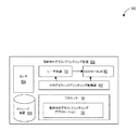
図1は、一実施例に係る動的ホログラフィプリンティング装置の一例を示すブロック図である。動的ホログラフィプリンティング装置106は、レーザ光源110と、LCOS−SLM112と、ホログラフィックプリンティング制御部102と、プロセッサ114と、センサ104と、ストレージ装置108と、を含む。
FIG. 1 is a block diagram showing an example of a dynamic holography printing device according to an embodiment. The dynamic
レーザ光源110は、(一または複数の)レーザビーム(例えば少なくとも1Wのレーザビーム)を生成する。レーザ光源110は、(一または複数の)レーザビームをLCOS−SLM112に導く。LCOS−SLM112は、プロセッサ114からの信号データに基づいて入射レーザビーム(例えば、レーザ光源110からのレーザ光)を、生成反射光(例えば変調レーザ光)に変調する。LCOS−SLM112からの変調されたレーザ光は、ホログラフィック波面を形成する。ホログラフィック波面の建設的干渉点で熱が形成される。入射レーザビームの変調、入射レーザビームの数、レーザビームの強度および方向などを調整することにより、熱を成形、制御および操作することができる。熱は、3次元プリンティングのためのターゲット材料における特定の3次元領域を硬化するために利用することができる。すなわち、空間光変調器に表された1つ以上のホログラムを制御することにより、加熱領域の形状を制御することができる。いくつかの実施形態では、空間光変調器は、受信光を少なくとも1つの対応焦点に導くために、少なくとも1つの位相限定レンズを与えるように構成される。いくつかの実施形態では、空間光変調器は、対応焦点を制御可能に位置づけるために、少なくとも1つの位相限定レンズと、少なくとも1つの対応する回折格子とを与えるように構成される。
The
ホログラフィックプリンティング制御部102は、プロセッサ114によって特定されたパターンに基づいて、レーザ光源110へのレーザ制御信号と、LCOS−SLM112へのLCOS−SLM112制御信号とを生成する。
The holographic
プロセッサ114は、干渉領域(例えば加熱領域)を制御し操作するための動的ホログラフィプリンティングアプリケーション118を含む。動的ホログラフィプリンティングアプリケーション118は、プリンティングパターンおよびLCOS−SLM112の表面に対する位置を特定する。プリンティングパターンおよびターゲット材料表面までの距離は、ユーザによって選択されてもよいし、センサ104からのデータに基づいて決定されてもよい。
一実施例では、動的ホログラフィプリンティングアプリケーション118は、所望のプリンティングパターン(例えば3次元の対象のモデル)に相当する、ターゲット材料上の所与の空間位置を特定する。動的ホログラフィプリンティングアプリケーション118は、複数の変調された入射レーザビームの焦点位置が所与の空間位置に一致するように調整するために、LCOS−SLM制御信号およびレーザ制御信号を生成する。LCOS−SLM112は、対応領域を硬化させることによりターゲット材料内に3D対象を形成するために、所与の空間的位置に基づいて、干渉点に加熱/高強度領域を生成する。
In one embodiment, the dynamic
別の実施例では、動的ホログラフィプリンティングアプリケーション118は、LCOS−SLM112に隣接する所与の空間的位置の第1の組を特定し、この所与の空間的位置の第1の組に基づいて、レーザ制御信号およびLCOS−SLM制御信号を調整する。動的ホログラフィプリンティングアプリケーション118は、所与の空間的位置の第1の組に基づいて、変調されたレーザ光ビームの組の焦点の組を決定する。LCOS−SLM112は、変調されたレーザ光ビームの組の焦点の組に基づいて、個別にフォーカスされた光照射野領域を干渉点に形成する。
In another embodiment, the dynamic
別の実施例では、動的ホログラフィプリンティングアプリケーション118は、所与の空間的位置の別の組を特定し、この所与の空間的位置の別の組に基づいて、レーザ制御信号およびLCOS−SLM制御信号を調整する。動的ホログラフィプリンティングアプリケーション118は、この所与の空間的位置の別の組に基づいて、変調されたレーザ光ビームの組の焦点の組を決定する。LCOS−SLM112は、この所与の空間的位置の別の組に基づく変調されたレーザ光の焦点に基づく干渉点への焦点の組に基づいて、プラズマの位置を干渉点から変更する。
In another embodiment, the dynamic
別の実施例では、動的ホログラフィプリンティングアプリケーション118は、3次元コンテンツ(例えば3Dモデル)に基づいて、空間的位置および幾何学的プリンティングパターンの特定を受信する。動的ホログラフィプリンティングアプリケーション118は、空間的位置および幾何学的プリンティングパターンの特定に相当する焦点の組を特定する。動的ホログラフィプリンティングアプリケーション118は、この焦点の組に基づいて、レーザ制御信号およびLCOS−SLM制御信号を調整する。この焦点の組に基づいて、干渉点で熱が形成される。いくつかの実施形態では、第2の焦点の組に基づいて、干渉点にプラズマが形成される。これらの実施形態では、プラズマは局在化した熱の原因となる。
In another embodiment, the dynamic
別の実施例では、動的ホログラフィプリンティングアプリケーション118は、プラズマの空間的位置および幾何学的プリンティングパターンの特定を受信し、この空間的位置および幾何学的プリンティングパターンの特定に相当する干渉点の組を特定する。動的ホログラフィプリンティングアプリケーション118は、この干渉点の組に基づいて、焦点の第2の組を特定し、この焦点の第2の組に基づいて、レーザ制御信号およびLCOS−SLM制御信号を調整する。第2の焦点の組に基づいて、干渉点にプラズマが形成されてよい。
In another embodiment, the dynamic
別の実施例では、プロセッサ114は、センサ104で検知された物理的対象に関するコンテンツをストレージ装置108から読み出す。ある実施例では、動的ホログラフィプリンティングアプリケーション118は、特定の物理的対象(例えばボール)を特定し、その位置とプリンティングパターン(例えばボールの3Dモデル)を生成する。
In another embodiment, the
センサ104は、例えば温度計、赤外線カメラ、バロメータ、湿度計、EEGセンサ、近接または位置センサ(近距離無線通信、GPS、ブルートゥース(登録商標)、WiFi(登録商標)等)、光学センサ(カメラ等)、方向センサ(ジャイロスコープ等)、音響センサ(マイクロフォン等)、その他これらの任意の好適な組み合わせを含む。本明細書に記載されたセンサは説明を目的とするものであり、センサ104はこれらに限定されないことに注意されたい。 The sensor 104 includes, for example, a thermometer, an infrared camera, a barometer, a hygrometer, an EEG sensor, a proximity or position sensor (short-range wireless communication, GPS, Bluetooth (registered trademark), WiFi (registered trademark), etc.), an optical sensor (camera, etc.). ), Directional sensors (gyroscopes, etc.), acoustic sensors (microphones, etc.), and any other suitable combination thereof. It should be noted that the sensors described herein are for illustration purposes only and the sensor 104 is not limited thereto.
ストレージ装置108は、センサの特定およびそれらのそれぞれの機能を蓄積する。
ストレージ装置108は、視覚的参照(画像、視覚的識別子、画像の特徴等)および対応するプラズマの幾何学的形状やパターン(球面、ビーム、立方体等)のためのデータベースをさらに含む。
The storage device 108 stores the identification of the sensors and their respective functions.
The storage device 108 further includes a database for visual references (images, visual identifiers, image features, etc.) and corresponding plasma geometry and patterns (spheres, beams, cubes, etc.).
ある実施形態では、動的ホログラフィプリンティング装置106は、視覚的参照のデータベース部分を読み出すために、コンピュータネットワークを介してサーバと通信してよい。コンピュータネットワークは、マシン、データベースおよび装置(例えば動的ホログラフィプリンティング装置106)との間の通信を可能とする任意のネットワークであってよい。従ってコンピュータネットワークは、有線ネットワーク、無線ネットワーク(モバイルまたは携帯電話ネットワーク等)その他これらの任意の好適な組み合わせであってよい。コンピュータネットワークは、プライベートネットワーク、公衆ネットワーク(インターネット等)その他これらの任意の好適な組み合わせを構成する1つ以上の部分を含んでよい。
In certain embodiments, the dynamic
本明細書に記載される1つ以上のモジュールは、ハードウェア(マシンのプロセッサ等)またはハードウェアとソフトウェアとの組み合わせを用いて実現されてよい。例えば本明細書に記載される任意のモジュールは、本明細書に記載される当該モジュールのための操作を実行するプロセッサを構成してよい。さらにこれらの任意の2つ以上のモジュールが組み合わされて単一モジュールになってもよく、本明細書に記載の単一のモジュールのための機能が複数のモジュールに分割されてもよい。さらに種々の実施例に従い、本明細書に記載の単一のマシン、データベースまたは装置に実装されたモジュールが、複数のマシン、データベースまたは装置に分散されてもよい。 The one or more modules described herein may be implemented using hardware (such as a processor in a machine) or a combination of hardware and software. For example, any module described herein may constitute a processor that performs the operations for that module described herein. Further, any two or more of these modules may be combined into a single module, and the functions for a single module described herein may be divided into a plurality of modules. Further, according to various embodiments, modules implemented in a single machine, database or device described herein may be distributed across multiple machines, databases or devices.
図2は、一実施例に係る動的ホログラフィプリンティング装置の別の例を示すブロック図である。動的ホログラフィプリンティング装置106は、LCOS−SLM112と、LCOS−SLM制御部202と、レーザ光源110と、レーザ制御部204と、ホログラフィックプリンティング制御部102と、動的ホログラフィプリンティングアプリケーション118を含むプロセッサ114と、を含む。
FIG. 2 is a block diagram showing another example of the dynamic holography printing device according to one embodiment. The dynamic
動的ホログラフィプリンティングアプリケーション118は、加熱(またはプリンティング)パターンを特定し、加熱パターンを生成するために、ホログラフィック波の干渉点の位置およびパターンを計算する。動的ホログラフィプリンティングアプリケーション118は、干渉点の位置およびパターンを、ホログラフィックプリンティング制御部102に通知する。別の実施例では、動的ホログラフィプリンティングアプリケーション118は、干渉点の位置およびパターンを計算し、計算された干渉点の位置およびパターンに基づいて、ホログラフィックプリンティング制御部102へのレーザ制御信号およびLCOS−SLM制御信号を生成する。
The dynamic
ホログラフィックプリンティング制御部102は、レーザ制御信号をレーザ制御部204に送信する。ホログラフィックプリンティング制御部102はまた、LCOS−SLM制御信号をレーザ制御部204に送信する。レーザ制御部204は、レーザ光源110の強度、ビーム数およびビーム方向を制御するためのレーザ制御信号を生成および通信する。LCOS−SLM制御部202は、LCOS−SLM112を制御するためのLCOS−SLM制御信号を生成および通信する。LCOS−SLM112は、波面干渉がエネルギー(例えば熱)を生成するように、レーザ光源からのレーザ光を変調する。
The holographic
図2は、LCOS−SLM112に導かれる第1の入射レーザビームおよび第2の入射レーザビームを生成する、レーザ光源110を示す。LCOS−SLM112は、第1の組のホログラフィック光照射野214(例えば第1のホログラフィック波面)への第1の入射レーザビームと、第2の組のホログラフィック光照射野216(例えば第2のホログラフィック波面)への第2の入射レーザビームとを生成する。第1の組のホログラフィック光照射野214と、第2の組のホログラフィック光照射野216との間の建設的干渉により、熱が生成される。熱の形状および位置は、レーザ制御部204およびLCOS−SLM制御部202への制御信号を調整することにより、制御および操作することができる。
FIG. 2 shows a
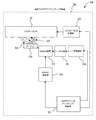
図3は、一実施例に係る動的ホログラフィプリンティング装置の別の例を示すブロック図である。動的ホログラフィプリンティング装置106は、LCOS−SLM112と、LCOS−SLM制御部202と、レーザ光源110と、レーザ制御部204と、MEMS装置302と、MEMS制御部304と、を含む。
FIG. 3 is a block diagram showing another example of the dynamic holography printing device according to one embodiment. The dynamic
動的ホログラフィプリンティングアプリケーション118は、パターンを特定し、3次元の加熱パターンを生成するために、ホログラフィック波の干渉点の位置およびパターンを計算する。動的ホログラフィプリンティングアプリケーション118は、干渉点の位置およびパターンを、ホログラフィックプリンティング制御部102に通知する。
The dynamic
ホログラフィックプリンティング制御部102は、レーザ制御信号をレーザ制御部204に送信する。ホログラフィックプリンティング制御部102はまた、LCOS−SLM制御信号をレーザ制御部204に送信する。ある実施例では、ホログラフィックプリンティング制御部102は、MEMS制御信号をMEMS制御部304に送信する。
The holographic
MEMS制御部304は、レーザ光源110からのレーザビームの方向を制御するために、MEMS制御信号をMEMS装置302に通信する。ある実施例では、MEMS制御部304は、レーザ光源110およびMEMS装置302の両方への同期信号を生成する。同期信号により、MEMS装置302は、レーザ光源110からの対応する個別の光ビームを操作し反射することができる。
The
MEMS装置302は、1つ以上のレーザビームをレーザ光源110から受光し、対応する個別の光ビームをLCOS−SLM112に向けて反射する。対応する個別の光ビームを、LCOS−SLM112の対応する位置に導くために、MEMS装置302は、MEMS制御部304またはホログラフィックプリンティング制御部102からの同期信号に基づいて、光ビームを反射する。MEMS装置302は、例えば1つ以上のミラーを含む。ミラーの位置および向きは、MEMS制御部304から受信した同期信号に基づいて、制御および調整される。
The
図4は、一実施例に係る動的ホログラフィプリンティング装置を用いたプリンティング操作の例を示すブロック図である。動的ホログラフィプリンティングアプリケーション118は、3次元の加熱パターンを特定し、3次元の加熱パターンを生成するために、ホログラフィック波の干渉点の位置およびパターンを計算する。動的ホログラフィプリンティングアプリケーション118は、干渉点の位置およびパターンを、ホログラフィックプリンティング制御部102に通知する。
FIG. 4 is a block diagram showing an example of a printing operation using the dynamic holography printing device according to the embodiment. The dynamic
図4は、LCOS−SLM112に導かれる第1の入射レーザビームおよび第2のレーザビームを生成する、レーザ光源110を示す。LCOS−SLM112は、第1の組のホログラフィック光照射野402(例えば第1のホログラフィック波面)への第1の入射レーザビームと、第2の組のホログラフィック光照射野404(例えば第2のホログラフィック波面)への第2の入射レーザビームとを変調する。第1の組のホログラフィック光照射野402と、第2の組のホログラフィック光照射野404との間の建設的/破壊的干渉406により、熱が生成される。干渉406の形状および位置は、レーザ制御部204およびLCOS−SLM制御部202への制御信号を調整することにより、制御および操作することができる。
FIG. 4 shows a
動的ホログラフィプリンティング装置106は、ホログラフィック光照射野を空間的に移動して調整することができる。例えばターゲット206は、干渉406で固形化する硬化性または易焼結性の材料を含む。硬化方向408は、硬化/焼結の位置が調整可能となるように波面が調整可能であることを示し、これにより複数点における固形化が実現する。
The dynamic
別の実施例では、複数の組ホログラフィック光照射野を生成することにより、複数領域(406、410、412)の干渉が同時に形成されてよい。複数領域の干渉は、3Dプリント対象に対応する3次元の空間領域を形成する。いくつかの実施形態では、各ホログラフィック光照射野は、1つのSLM(または共通のSLM)上のそれぞれのホログラムによって形成される。いくつかの実施形態では、各ホログラムは、各ホログラフィック光照射野のサイズ、形状および位置が正確に制御できるようなレンズ機能および/または回折格子機能をもたらす、ホログラフィックデータを含む。いくつかの実施形態では、加熱、硬化および3Dプリンティングの少なくとも一つに必要な光強度を得るために、ホログラフィック光照射野は干渉(例えば建設的干渉)を受ける。 In another embodiment, interference in multiple regions (406, 410, 412) may be formed simultaneously by generating multiple pairs of holographic light fields. Interference in multiple regions forms a three-dimensional spatial region corresponding to the 3D print target. In some embodiments, each holographic light field is formed by a respective hologram on one SLM (or common SLM). In some embodiments, each hologram comprises holographic data that provides a lens function and / or a diffraction grating function that allows precise control of the size, shape and position of each holographic light field. In some embodiments, the holographic light field is subject to interference (eg, constructive interference) in order to obtain the light intensity required for at least one of heating, curing and 3D printing.
図5は、一実施例に係る3次元プリント対象の例を示すブロック図である。動的ホログラフィプリンティングアプリケーション118は、図4に関連する前述の技術を用いて、複数領域のホログラフィック光照射野(510、512、502)を生成する。組み合わされた領域510、512、502は、ターゲット206の材料内部に硬化された3次元の対象504を形成する。再び、対応するソフトウェアレンズの光学パワーを選択することにより、ターゲット材料内部に、異なる深さでホログラフィック光照射野が生成されてよい。
FIG. 5 is a block diagram showing an example of a three-dimensional print target according to an embodiment. The dynamic
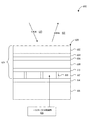
図6は、一例に係るLCOS−SLM(シリコン上液晶空間光変調器)の断面を示す図である。LCOS−SLM628は、単一のシリコン結晶基板616を用いて形成される。基板616は、ギャップ618により分離して配置され、基板616の上面に設置された、正方形の平面状アルミニウム電極612の2次元アレイを備える。電極612は、基板616内に埋め込まれた回路614を介して、基板616に接続される。電極612の各々は、それぞれ平面状のミラーを形成する。電極612は、LCOS−SLM制御部626に接続されてよい。換言すれば、電極612は、LCOS−SLM制御部626から制御信号を受信する。
FIG. 6 is a diagram showing a cross section of an LCOS-SLM (liquid crystal spatial light modulator on silicon) according to an example. The LCOS-SLM628 is formed using a single
調整層610が、電極612の2次元アレイの頂部に配置される。液晶層608が、調整層610の上に配置される。
The
第2調整層606が、液晶層608の頂部に配置される。平面状透明層602(例えばガラス製)が、第2調整層606の頂部に配置される。単一の透明電極604が、平面状透明層602と第2調整層606との間に配置される。
The
正方形の電極612の各々は、透明電極604のオーバレイ領域および介在する液晶層608とともに、制御可能な位相変調素子624(ピクセルとも呼ばれる)を定義する。効果的なピクセル領域(またはフィルファクタ)は、ピクセル間の空間またはギャップ618を考慮した上で、光学活性なピクセル全体の割合である。各電極612に付加される電圧を透明電極604に関連して制御することにより、それぞれの位相変調素子の液晶材料(液晶層608内の液晶)の特性は変化し得る。位相変調素子を変化させることにより、入射光620の遅延を変化させることができる。その効果として、波面に位相限定変調が与えられる(すなわち、結果として得られる変調光に強度的な効果は発生しない)。
Each of the
反射型LCOS空間光変調器を用いる利点の1つは、透過型デバイスを用いた場合と比べて、液晶層の厚さを半分にできる点である。これにより液晶のスイッチング速度を大幅に改善することができる(これは、動画像ビデオを表示する上でのキーポイントである)。別の利点は、LCOSデバイスはまた位相限定素子の巨大なアレイを小さな開口で表示できる点である。素子が小さい(典型的には約10ミクロン以下)ことにより、光学システムに非常に長い光路長を与える必要なく、実用的な回折角(数度)を得ることができる。 One of the advantages of using a reflective LCOS spatial light modulator is that the thickness of the liquid crystal layer can be halved as compared to the case of using a transmissive device. This can greatly improve the switching speed of the liquid crystal (this is a key point in displaying moving image video). Another advantage is that LCOS devices can also display a large array of phase limiting elements with a small aperture. Due to the small size of the device (typically about 10 microns or less), a practical diffraction angle (several degrees) can be obtained without having to give the optical system a very long optical path length.
LCOS−SLM628の小さな開口(数平方センチメートル)を適切に照射することは、より大きな液晶デバイスの開口の場合と比べて容易である。またLCOS−SLMは大きな開口比を持ち、ピクセル間のデッドスペースは非常に小さい(なぜなら、ピクセルを駆動するための回路はミラーの下に埋め込まれているからである)。開口が小さいことにより、再生領域における光学ノイズが低減される。 Properly irradiating a small aperture (several square centimeters) of the LCOS-SLM628 is easier than with a larger liquid crystal device aperture. LCOS-SLM also has a large aperture ratio and very small dead space between pixels (because the circuit for driving the pixels is embedded under the mirror). The small aperture reduces optical noise in the reproduction region.
シリコンバックプレーン(例えばシリコン基板616)を用いることのもう1つの利点は、位相変調デバイスにとって重要であることに、ピクセルが光学的に平坦である点である。 Another advantage of using a silicon backplane (eg, silicon substrate 616) is that the pixels are optically flat, which is important for phase modulation devices.
実施形態が反射型LCOS−SLMに関する一方、当業者は、透過型SLMを含む他のタイプのSLMも使用可能であることを認識するだろう。 While embodiments relate to reflective LCOS-SLMs, those skilled in the art will recognize that other types of SLMs, including transmissive SLMs, are also available.
図7は、一実施例に係る動的ホログラフィプリンティング装置の操作の他の例を示すフロー図である。ブロック704で、動的ホログラフィプリンティングアプリケーション118は、所与の空間位置(例えばターゲット材料内の所望の位置)の特定を受信する。ブロック706で、動的ホログラフィプリンティングアプリケーション118は、所与の空間位置に対応するホログラフィック波面の干渉点の位置を(LCOS−SLM112によって生成できるように)計算する。ブロック708で、動的ホログラフィプリンティングアプリケーション118は、ホログラフィック波面の干渉点の位置に対応する焦点の位置を算出する。ブロック710で、動的ホログラフィプリンティングアプリケーション118は、ホログラフィック波面を生成するために、焦点の位置に基づいて、レーザ光源110へのレーザ制御信号およびLCOS−SLM112へのLCOS−SLM制御信号を生成する。
FIG. 7 is a flow chart showing another example of the operation of the dynamic holography printing device according to one embodiment. At
図8は、一実施例に係る動的ホログラフィプリンティング装置の操作の他の例を示すフロー図である。ブロック804で、レーザ制御部204は、レーザビームの強度、レーザビームの方向およびレーザビームの数を制御するために、レーザ光源110へのレーザ制御信号を生成する。ブロック806で、LCOS−SLM制御部202は、LCOS−SLM112に導かれる入射光ビームの変調を制御するために、LCOS−SLM112へのLCOS−SLM制御信号を生成する。ブロック810で、LCOS−SLM112は、レーザ光源110からの入射レーザビームを変調する。ブロック812で、LCOS−SLM112は、変調されたレーザビームからホログラフィック波面を形成する。ブロック814で、ホログラフィック波面の干渉点の位置で熱が生成され、熱が対応する熱の位置でターゲット材料を硬化させる。
FIG. 8 is a flow chart showing another example of the operation of the dynamic holography printing device according to one embodiment. At
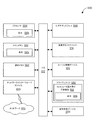
図9は、一実施例に係る動的ホログラフィプリンティング装置の操作の他の例を示すフロー図である。ブロック904で、動的ホログラフィプリンティングアプリケーション118は、3次元の対象に相当するプリンティングデータを受信する。ブロック906で、動的ホログラフィプリンティングアプリケーション118は、プリンティングデータに基づいて、ターゲット材料内部の干渉点の位置を計算する。ブロック908で、動的ホログラフィプリンティングアプリケーション118は、干渉点の位置に相当する焦点の位置を算出する。ブロック910で、動的ホログラフィプリンティングアプリケーション118は、焦点に基づいてホログラフィック波面を形成するために、レーザ光源110へのレーザ制御信号およびLCOS−SLM112へのLCOS−SLM制御信号を生成する。
FIG. 9 is a flow chart showing another example of the operation of the dynamic holography printing device according to one embodiment. At
図10は、いくつかの実施例に従い、マシン1000の部品を示すブロック図である。
マシン1000は、コンピュータ読み取り可能媒体1018(例えば、非一過性マシン読み取り可能媒体、マシン読み取り可能ストレージ媒体、コンピュータ読み取り可能ストレージ媒体、その他それらの任意の好適な組み合わせ)から命令1006を読み出すことができ、本明細書に記載の任意の1つ以上の方法を全体的にまたは部分的に実行することができる。特に、本例のマシン1000は、本明細書に記載の任意の1つ以上の方法を全体的にまたは部分的にマシン1000に実行させるための命令(例えばソフトウェア、プログラム、アプリケーション、アプレット、app、その他の実行可能可能コード)が内部で実行可能な、コンピュータシステム(例えばコンピュータ)を構成する。
FIG. 10 is a block diagram showing parts of the
The
代替的な実施形態では、マシン1000は、スタンドアロン装置として動作してよく、あるいは他のマシンと通信可能に結合(例えばネットワーク化)されてよい。ネットワーク化された構成では、マシン1000は、サーバクライアント環境内のサーバマシンまたはクライアントマシンの役割で動作してよく、あるいは分散ネットワーク(例えばピア・トゥ・ピア)ネットワーク環境内のピアマシンとして動作してもよい。マシン1000は、サーバコンピュータ、クライアントコンピュータ、パーソナルコンピュータ(PC)、タブレットコンピュータ、ラップトップコンピュータ、携帯電話、スマートフォン、セットトップボックス(STB)、携帯情報端末(PDA)、ウェブアプライアンス、ネットワークルータ、ネットワークスイッチ、ネットワークブリッジなどであってよく、また命令1006(すなわちマシンが実行する動作を特定する命令)を連続的にまたはその他の仕方で実行可能な任意のマシンであってよい。さらに、単一のマシンのみが記載されるが、「マシン」という用語はまた、個別にまたは共同して命令1006を実行し、本明細書に記載の任意の1つ以上の方法を全体的にまたは部分的に実行する複数のマシンの集合を含むと解釈されてよい。
In an alternative embodiment, the
マシン1000は、プロセッサ1004(例えば中央処理装置(CPU))、グラフィック処理装置(GPU)、デジタル信号処理プロセッサ(DSP)、特定用途向け集積回路(ASIC)、高周波集積回路(RFIC)その他これらの任意の好適な組み合わせ)、メインメモリ1010および静的メモリ1022を含み、これらはバス1012を介して互いに通信するように構成される。プロセッサ1004は、プロセッサ1004が本明細書に記載の任意の1つ以上の方法を全体的にまたは部分的に実行するために構成されるように、命令1006の一部または全部を用いて一時的または永久的に設定可能な、固体デジタルマイクロ回路(例えば電気的、光学的、またはその両方)を含む。例えば、プロセッサ1004の1つ以上のマイクロ回路の組は、本明細書に記載の1つ以上のモジュール(例えばソフトウェアモジュール)を実行するように設定可能であってよい。いくつかの実施例では、プロセッサは、内部で複数のコアの各々が本明細書に記載の任意の1つ以上の方法を全体的にまたは部分的に実行することのできる別個のプロセッサとして振る舞うマルチCPU(例えばデュアルコアCPU、クアッドコアCPU、または128コアCPU)である。本明細書に記載の有利な効果は少なくともプロセッサ1004を備えるマシン1000によって与えられるが、プロセッサレスマシンが本明細書に記載の1つ以上の方法を実行するように構成された場合は、同等の有利な効果がプロセッサを備えない別種のマシン(例えば純粋機械システム、純粋油圧システム、または機械油圧ハイブリッドシステム)によって与えられてよい。
The
マシン1000は、ビデオディスプレイ1008(例えばプラズマディスプレイパネル(PDP))、発光ダイオード(LED)ディスプレイ、液晶(LCD)ディスプレイ、プロジェクタ、ブラウン管(CRT)その他の、画像やビデオを表示可能な任意のディスプレイをさらに含んでよい。マシン1000はまた、英数字入力デバイス1014(例えばキーボードまたはキーパッド)、カーソル制御デバイス1016(例えばマウス、タッチパッド、トラックボール、ジョイスティック、モーションセンサ、アイトラッキングデバイスその他のポインティング手段)、ドライブユニット1002、信号発生デバイス1020(例えばサウンドカード、アンプ、スピーカ、ヘッドホンジャックまたはこれらの任意の好適な組み合わせ)、およびネットワークインターフェースデバイス1024を含んでよい。
The
ドライブユニット1002(例えばデータストレージ装置)は、本明細書に記載の任意の1つ以上の方法また機能を具現化する命令1006が蓄積されるコンピュータ読み取り可能媒体1018(例えば有形かつ非一過性マシン読み取り可能媒体)を含む。命令1006はまた、マシンの1000による実行前または実行中、その全体または少なくとも一部が、メインメモリ1010の中、プロセッサ1004の中(例えばプロセッサのキャッシュメモリの中)またはその両方の中にあってよい。従って、メインメモリ1010およびプロセッサ1004は、マシン読み取り可能媒体(例えば有形かつ非一過性マシン読み取り可能媒体)であると考えられてよい。命令1006は、ネットワークインターフェースデバイス1024を介して、コンピュータネットワーク上で伝達または受信されてよい。例えば、ネットワークインターフェースデバイス1024は、任意の1つ以上の通信プロトコル(例えばハイパーテキストトランスファープロトコル(HTTP))を用いて、命令1006を通信してよい。
The drive unit 1002 (eg, a data storage device) is a computer-readable medium 1018 (eg, a tangible and non-transient machine read) in which instructions 1006 embodying any one or more of the methods or functions described herein are stored. Possible media) included. Instruction 1006 is also in the main memory 1010, in the processor 1004 (eg in the processor cache memory), or both, before or during execution by the
いくつかの実施例では、マシン1000は、携帯型計算装置(例えばスマートフォン、タブレットコンピュータその他のウェアラブルデバイス)であってよく、1つ以上の追加的な入力部品(例えばセンサやゲージ)を有してよい。このような入力部品の例は、画像入力部品(例えば1つ以上のカメラ)、音響入力部品(例えば1つ以上のマイクロホン)、向き入力部品(例えばコンパス)、位置入力部品(例えばグルーバルポジショニングシステム(GPS)受信機)、方向部品(例えばジャイロスコープ)、モーション検知部品(例えば1つ以上の加速度センサ)、高度検知部品(例えば1つ以上の高度計)、バイオメトリック入力部品(例えば心拍計や血圧計)およびガス検知部品(例えばガスセンサ)を含む。これらの1つ以上の任意の入力部品で収集された入力データは、本明細書に記載の任意のモジュールでの使用のためにアクセス可能であり入手可能であってよい。
In some embodiments, the
本明細書で用いられる「メモリ」という用語は、データを一時的または永久に蓄積可能なマシン読み取り可能媒体のことをいい、例えば、ランダムアクセスメモリ(RAM)、リードオンリーメモリ(ROM)、バッファメモリ、フラッシュメモリ、およびキャッシュメモリなどを含む(しかし限定されない)と解釈されてよい。実施例ではコンピュータ読み取り可能媒体1080が単一媒体として記述されるが、「マシン読み取り可能媒体」という用語は、命令を蓄積可能な単一媒体または複数媒体(例えば集中データベースまたは分散データベース、あるいは関連するキャッシュおよびサーバ)を含むと解釈されるべきである。「コンピュータ読み取り可能媒体」という用語はまた、マシン1000による実行命令1006を蓄積可能な任意の媒体または複数の媒体の組み合わせを含むと理解されてよい。ここで、この命令1006がマシン1000の1つ以上のプロセッサ(例えばプロセッサ1004)で実行されると、前述の任意の1つ以上の方法が、全体的または部分的にマシン1000により実行される。従って「マシン読み取り可能媒体」は、単一の蓄積装置またはデバイスを指すとともに、クラウドベースのストレージシステムや、複数の蓄積装置またはデバイスを含むストレージネットワークを指す。従って「マシン読み取り可能媒体」という用語は、例えば固体メモリチップ、光ディスク、磁気ディスクその他これらの任意の好適な組み合わせといった形態の1つ以上の具体的かつ非一過性のデータ収納場所(すなわちデータボリューム)を含む(しかし限定されない)と解釈されるべきである。本明細書で用いられる「非一過性」マシン読み取り可能媒体は、特に伝播信号自体を含まない。いくつかの実施形態例では、マシン1000による実行のための命令1006は搬送媒体を用いて通信されてもよい。このような搬送媒体の例は、ストレージ媒体(例えば固体メモリなどの非一過性マシン読み取り可能媒体で、ある場所から他の場所に物理的に移動されるもの)と、一時的媒体(例えば命令1006を通信する伝送信号)とを含む。
As used herein, the term "memory" refers to a machine-readable medium that can store data temporarily or permanently, such as random access memory (RAM), read-only memory (ROM), buffer memory. , Flash memory, and cache memory, etc., may be interpreted as including (but not limited to). Although the computer readable medium 1080 is described as a single medium in the embodiments, the term "machine readable medium" refers to a single medium or multiple media (eg, centralized or distributed database, or related) capable of accumulating instructions. Should be interpreted as including cache and server). The term "computer-readable medium" may also be understood to include any medium or a combination of multiple media capable of accumulating execution instructions 1006 by the
本明細書に記載のある実施例は、モジュールを含むと記載される。モジュールはソフトウェアモジュール(例えば保存されたコード、またはマシン読み取り可能媒体や伝送媒体中でその他の方法により具現化されたコード)、ハードウェアモジュールまたはこれらの任意の好適な組み合わせを構成してよい。「ハードウェアモジュール」は、ある命令を実行可能な有形の(例えば非一過性の)物理的な部品(例えば1つ以上のプロセッサの組)であり、何らかの物理的な方法で構成され配置されてよい。様々な実施例で、1つ以上のコンピュータシステムまたはそれらの1つ以上のハードウェアモジュールは、ソフトウェア(例えばアプリケーションやその一部)により、本明細書に記載の当該モジュールのための操作を実行するために動作するハードウェアモジュールとして構成されてよい。 The examples described herein are described as including modules. The module may constitute a software module (eg, stored code, or code embodied in a machine-readable or transmission medium by other means), a hardware module, or any suitable combination thereof. A "hardware module" is a tangible (eg, non-transient) physical component (eg, a set of one or more processors) capable of executing an instruction, configured and arranged in some physical way. You can. In various embodiments, one or more computer systems or one or more hardware modules thereof perform the operations for such modules described herein by software (eg, an application or part thereof). It may be configured as a hardware module that works for.
いくつかの実施例では、ハードウェアモジュールは、機械的に、電気的に、油圧的にまたはこれらの任意の好適な組み合わせにより具現化されてよい。例えばハードウェアモジュールは、ある操作を実行するように永久的に構成される専用の回路またはロジックを含んでよい。ハードウェアモジュールは、フィールドプログラマブルゲートアレイ(FPGA)やASICなどの特定目的プロセッサであってよく、これらを含んでもよい。ハードウェアモジュールは、ある操作を実行するようにソフトウェアにより一時的に構成される、プログラム可能なロジックまたは回路を含んでもよい。一例として、ハードウェアモジュールは、CPUその他のプログラム可能なプロセッサに包含されるソフトウェアを含んでよい。ハードウェアモジュールを、機械的に、油圧的に、専用の永久的に構成した回路内に具現化するか、あるいは一時的に構成した(例えばソフトウェアで構成した)回路内に具現化するかに関する決定は、コストや時間を考慮してされてよいことは理解されるだろう。 In some embodiments, the hardware module may be embodied mechanically, electrically, hydraulically or by any suitable combination thereof. Hardware modules, for example, may include dedicated circuits or logic that are permanently configured to perform certain operations. The hardware module may be a special purpose processor such as a field programmable gate array (FPGA) or an ASIC, and may include these. Hardware modules may include programmable logic or circuits that are temporarily configured by software to perform certain operations. As an example, a hardware module may include software contained in a CPU or other programmable processor. Determining whether a hardware module is mechanically, hydraulically, or embodied in a dedicated, permanently configured circuit or in a temporarily configured (eg, software) circuit. Will be understood that cost and time may be taken into account.
従って「ハードウェアモジュール」という表現は、物理的に、永久的に(例えば配線され)あるいは一時的に構成される(例えばプログラムされる)ものであって、本明細書に記載の操作をある方法で操作または実行する有形の実体を含むことは理解されるべきである。さらに本明細書で使用される「ハードウェアで具現化されたモジュール」という表現は、ハードウェアモジュールのことをいう。ハードウェアモジュールが一時的に構成された(例えばプログラムされた)実施例を考慮すると、ハードウェアモジュールの各々は、時間的に同時に構成または具体化される必要はない。例えば、ハードウェアモジュールがソフトウェアにより特定目的のプロセッサに設定されるCPUを含む場合、該CPUは、異なる時に、それぞれ異なる特定目的のプロセッサ(例えば異なるハードウェアモジュールに含まれる)に設定されてよい。従ってソフトウェア(例えばソフトウェアモジュール)は、1つ以上のプロセッサを設定し、例えば、時間的なある時にある特定ハードウェアモジュールになる(または構成する)ようにし、時間的な別の時に別のハードウェアモジュールになる(または構成する)ようにしてよい。 Thus, the expression "hardware module" is physically, permanently (eg, wired) or temporarily configured (eg, programmed), and the operations described herein are performed in some way. It should be understood to include tangible entities that operate or perform in. Furthermore, the expression "module embodied in hardware" as used herein refers to a hardware module. Considering an embodiment in which a hardware module is temporarily configured (eg, programmed), each of the hardware modules does not need to be configured or embodied simultaneously in time. For example, if a hardware module includes a CPU that is set to a particular purpose processor by software, the CPU may be set to different special purpose processors (eg, included in different hardware modules) at different times. Thus, software (eg, a software module) configures one or more processors, eg, to become (or configure) one particular hardware module at one time in time, and another hardware at another time in time. It may be a module (or configure).
ハードウェアモジュールは、他のハードウェアモジュールに情報を提供し、他のハードウェアモジュールから情報を受信することができる。従って、記載されるハードウェアモジュールは、通信可能に結合されていると考えられてよい。複数のハードウェアモジュールが同時に存在する場合、通信は2つ以上のハードウェアモジュール間の信号伝達(例えば好適な回路やバスを介した)により実現されてよい。複数のハードウェアが異なる時に構成または設定される実施形態では、こうしたハードウェアモジュール間の通信は、例えば該ハードウェアモジュールがアクセス可能なストレージやメモリ構造内の情報の読み出しにより実現されてよい。例えばハードウェアモジュールは、操作を実行し、該操作の結果を、通信可能に結合されたメモリ(例えばメモリデバイス)内に蓄積してよい。その後、さらなるハードウェアモジュールが該メモリにアクセスし、蓄積された結果を読み出して処理してもよい。ハードウェアモジュールはまた、入力または出力デバイスでの通信を初期化してもよく、リソース(例えば計算リソースからの情報の集合)上で動作してもよい。 A hardware module can provide information to other hardware modules and receive information from other hardware modules. Therefore, the hardware modules described may be considered communicably coupled. When a plurality of hardware modules exist at the same time, communication may be realized by signal transmission between two or more hardware modules (for example, via a suitable circuit or bus). In an embodiment in which a plurality of hardware is configured or set at different times, communication between such hardware modules may be realized, for example, by reading information in a storage or memory structure accessible to the hardware modules. For example, a hardware module may perform an operation and store the result of the operation in communicably coupled memory (eg, a memory device). After that, a further hardware module may access the memory, read the accumulated result, and process it. Hardware modules may also initialize communication on input or output devices and may operate on resources (eg, sets of information from computational resources).
本明細書に例示により記載された方法の種々の操作は、少なくとも部分的には、関連する操作を実行するように一時的に(例えばソフトウェアによって)または永久的に設定された1つ以上のプロセッサにより実行されてよい。構成が一時的であれ永久的でれ、このようなプロセッサは、本明細書に記載の1つ以上の操作または機能を実行するように動作するプロセッサ実現モジュールを構成してよい。本明細書で使用される「プロセッサ実現モジュール」という用語は、内部に1つ以上のプロセッサを含むハードウェアモジュールのことをいう。従って本明細書に記載の操作は、少なくとも部分的には、プロセッサ実現、ハードウェア実現またはその両方であってよい。なぜなら、プロセッサはハードウェアの一例であり、本明細書で検討された任意の1つ以上の方法内の少なくともいくつかの操作は、1つ以上のプロセッサ実現モジュール、ハードウェア実現モジュールまたはこれらの任意の好適な組み合わせで実行されてよいからである。 The various operations of the methods illustrated herein are, at least in part, one or more processors that are temporarily (eg, by software) or permanently configured to perform related operations. May be executed by. Such processors, whether temporary or permanent, may constitute processor implementation modules that operate to perform one or more of the operations or functions described herein. As used herein, the term "processor realization module" refers to a hardware module that contains one or more processors internally. Thus, the operations described herein may, at least in part, be processor realizations, hardware realizations, or both. Because a processor is an example of hardware, at least some operations within any one or more of the methods discussed herein are one or more processor realization modules, hardware realization modules or any of these. This is because it may be executed in a suitable combination of.
さらに、このような1つ以上のプロセッサは、「クラウドコンピューティング」環境で、またはそのサービス(例えば「Software as a Service」(SaaS))として操作を実行してよい。例えば、本明細書に記載で検討された任意の1つ以上の方法内の少なくともいくつかの操作は、コンピュータ群(例えばプロセッサを含むマシン群)で実行されてよく、これらの操作は、ネットワーク(例えばインターネット)および1つ以上の適切なインタフェース(例えばアプリケーションやプログラムインタフェース(API))を介してアクセス可能である。ある操作が単一のマシン内にあろうと複数のマシンをまたいで分散していようと、該操作は1つ以上のプロセッサの間で分散されて実行されてよい。いくつかの実施例では、1つ以上のプロセッサまたはハードウェアモジュール(例えばプロセッサ実現モジュール)は、1つの地理的位置(例えば宅内環境、オフィス環境またはサーバファーム内)にあってよい。他の実施例では、1つ以上のプロセッサまたはハードウェアモジュールは、複数の地理的位置をまたいで分散していてもよい。 In addition, one or more such processors may perform operations in a "cloud computing" environment or as a service thereof (eg, "Software as a Service" (Software as a Service)). For example, at least some of the operations within any one or more of the methods discussed herein may be performed on a group of computers (eg, a group of machines including a processor), and these operations may be performed on a network (eg, a group of machines including a processor). It is accessible via (eg, the Internet) and one or more suitable interfaces (eg, application or program interface (API)). Whether an operation is within a single machine or distributed across multiple machines, the operation may be distributed among one or more processors. In some embodiments, one or more processors or hardware modules (eg, processor realization modules) may be in one geographic location (eg, in a home environment, office environment, or server farm). In other embodiments, one or more processors or hardware modules may be distributed across multiple geographic locations.
本明細書全体を通して、単一の例として記載された部品、操作または構造を、複数の例が実現してよい。1つ以上の方法の個々の操作は別個の操作として記述され説明されているが、1つ以上の個々の操作が同時に実行されてもよく、これらの操作が本明細書で説明された順序で実行される必要もない。例示された構成では別個の部品または機能として示された構造およびその機能は、組み合わされた機能を有する組み合わされた構造または部品であってもよい。同様に、単一の部品として示された構造および機能は、別個の部品および機能として実現されてもよい。これらまたはその他の変形、修正、追加および改良は、本明細書の主題の範囲内にある。 Throughout this specification, multiple examples may implement the parts, operations or structures described as a single example. Although the individual operations of one or more methods are described and described as separate operations, one or more individual operations may be performed simultaneously and these operations are in the order described herein. It doesn't even have to be executed. The structure and its function shown as separate parts or functions in the illustrated configuration may be a combined structure or part having a combined function. Similarly, structures and functions shown as a single part may be realized as separate parts and functions. These or other modifications, modifications, additions and improvements are within the scope of the subject matter herein.
本明細書で検討された主題のある部分は、アルゴリズムで示されてもよく、あるいは、メモリ(例えばコンピュータメモリまたは他のマシンメモリ)内のビットまたはバイナリデジタル信号として蓄積されたデータ上の操作の記号表現で表されてもよい。このようなアルゴリズムまたは記号表現は、データ処理分野の当業者が、他の当業者に内容を伝えるために使用する技術の一例である。本明細書で使用される「アルゴリズム」は、自己矛盾のない操作または同様の処理の連続であって、所望の結果を導くものである。この文脈において、アルゴリズムおよび操作は、物理的実体の物理的操作を含む。典型的に、しかし必然的ではなく、このような実体は、記憶、アクセス、伝達、結合、比較などといったマシンによる操作が可能な、電気的、磁気的または光学的信号の形を取ってよい。主に共通的使用という目的から、このような信号は時に「データ」「コンテンツ」「ビット」「値」「エレメント」「記号」「文字」「ターム」「数」「数値」などといった用語を使って参照されてもよい。しかしながらこれらの単語は単なる便宜的なラベルであって、適切な物理的実体と関連すべきである。 Some parts of the subject matter discussed herein may be indicated by algorithms, or of operations on data stored as bits or binary digital signals in memory (eg, computer memory or other machine memory). It may be represented by a symbolic representation. Such algorithms or symbolic representations are examples of techniques used by those skilled in the art of data processing to convey content to others. As used herein, an "algorithm" is a sequence of self-consistent operations or similar processes that yields the desired result. In this context, algorithms and operations include the physical operations of physical entities. Typically, but not necessarily, such entities may take the form of electrical, magnetic or optical signals that can be manipulated by machines such as memory, access, transmission, coupling, comparison and the like. Such signals sometimes use terms such as "data", "content", "bits", "values", "elements", "symbols", "characters", "terms", "numbers", "numbers", etc., mainly for the purpose of common use. May be referred to. However, these words are merely expedient labels and should be associated with the appropriate physical entity.
特段の断りのない限り、本明細書で「アクセスする」「処理する」「検知する」「計算する」「算出する」「決定する」「生成する」「示す」「表示する」などといった用語を使ってなされた検討は、1つ以上のメモリ(例えば揮発性メモリ、不揮発性メモリまたはこれらの任意の好適な組み合わせ)、レジスタその他の情報を受信、蓄積、伝達または表示するマシン部品内の物理的(例えば電気的、磁気的または光学的)実体として表現されたデータを処理または変換するマシン(例えばコンピュータ)により実行可能な動作または処理のことをいう。さらに特許文献では共通であるように、特段の断りのない限り、本明細書で使用される「一つの(a、an)」という用語は1つ以上の例を含む。最後に、特段の断りのない限り、本明細書で使用される「または(or)」という接続詞は、非排他的な意味の「または」のことをいう。 Unless otherwise noted, terms such as "access," "process," "detect," "calculate," "calculate," "determine," "generate," "show," and "display" are used herein. The studies made using are physical in machine components that receive, store, transmit or display one or more memories (eg, volatile memory, non-volatile memory or any suitable combination thereof), registers and other information. An operation or process that can be performed by a machine (eg, a computer) that processes or transforms data represented as an entity (eg, electrical, magnetic, or optical). Further, as is common in patent literature, unless otherwise specified, the term "one (a, an)" as used herein includes one or more examples. Finally, unless otherwise noted, the conjunction "or" as used herein refers to the non-exclusive meaning of "or".
Claims (7)
前記方法は、
3次元対象に基づく画像データを受信し、ホログラムをリアルタイムに計算するステップと、
レーザ制御信号とLCOS−SLM制御信号を生成するステップであって、前記LCOS−SLM制御信号がリアルタイムで計算された前記ホログラムに基づくものと、
レーザ光源(110)を用いて、前記レーザ制御信号に基づいて、複数の入射レーザビームを生成するステップと、
LCOS−SLM(112)を用いて、前記LCOS−SLM制御信号に基づいて、前記複数の入射レーザビームを変調するステップと、
変調された前記複数の入射レーザビームから、複数のホログラフィック波面(402,404)を生成し、前記ホログラフィック波面の各々が少なくとも1つの対応する焦点を形成し、前記複数のホログラフィック波面(402,404)の前記焦点に基づいて複数の光照射野領域を生成するステップであって、前記複数の光照射野領域が前記ターゲット材料(206)内に形成される前記3次元対象の本体に相当するものと、
前記複数の光照射野領域の干渉により生じた熱で前記ターゲット材料(206)の部分を硬化するステップであって、前記ターゲット材料の部分が前記3次元対象の本体を含むものと、をこの順で備え、
前記レーザ制御信号とLCOS−SLM制御信号を生成するステップは、前記複数のホログラフィック波面(402,404)の前記焦点を決定するステップをさらに含み、前記複数のホログラフィック波面(402,404)の焦点は、フーリエ変換を実行するソフトウェアレンズと物理レンズの組み合わせにより決定され、前記ソフトウェアレンズは、前記ホログラムに含まれるレンズを表すデータであり、前記物理レンズは、前記LCOS−SLMであり、
前記レーザ制御信号と前記LCOS−SLM制御信号は、前記複数のホログラフィック波面(402,404)の前記焦点が形成されるように生成される、
方法。 A method of curing the target material (206) using holographic projection.
The method is
The step of receiving image data based on a 3D object and calculating the hologram in real time,
A step of generating a laser control signal and an LCOS-SLM control signal, wherein the LCOS-SLM control signal is based on the hologram calculated in real time.
A step of generating a plurality of incident laser beams based on the laser control signal using a laser light source (110), and
A step of modulating the plurality of incident laser beams based on the LCOS-SLM control signal using the LCOS-SLM (112).
A plurality of holographic wave planes (402, 404) are generated from the plurality of modulated incident laser beams, and each of the holographic wave planes forms at least one corresponding focal point, and the plurality of holographic wave planes (402) are formed. , 404), which is a step of generating a plurality of light irradiation field regions based on the focal point, and corresponds to the main body of the three-dimensional object in which the plurality of light irradiation field regions are formed in the target material (206). What to do and
The step of curing the portion of the target material (206) with the heat generated by the interference of the plurality of light irradiation field regions, in which the portion of the target material includes the main body of the three-dimensional object, in this order. Prepare with
The step of generating the laser control signal and the LCOS-SLM control signal further includes a step of determining the focal point of the plurality of holographic wave surfaces (402, 404), and the step of generating the plurality of holographic wave surfaces (402, 404). The focal point is determined by a combination of a software lens and a physical lens that perform a Fourier transform, the software lens is data representing a lens included in the hologram, and the physical lens is the LCOS-SLM.
The laser control signal and the LCOS-SLM control signal are generated so that the focal points of the plurality of holographic wave planes (402, 404) are formed.
Method.
変調された複数の入射レーザビームの焦点位置を、前記複数の空間位置に一致させるように調整するために、前記LCOS−SLM制御信号および前記レーザ制御信号を生成するステップと、をさらに備える
請求項1に記載の方法。 A step of providing a plurality of spatial positions in the target material (206) close to the LCOS-SLM (112), wherein the plurality of spatial positions correspond to the three-dimensional object.
Claim that further comprises a step of generating the LCOS-SLM control signal and the laser control signal in order to adjust the focal positions of the plurality of modulated incident laser beams to match the plurality of spatial positions. The method according to 1.
前記プリンティングデータに基づいて、前記ターゲット材料(206)内に領域を提供するステップと、
前記プリンティングデータに基づいて、前記ターゲット材料(206)内に前記領域に相当する第2の複数の焦点を提供するステップと、
前記第2の複数の焦点に基づいて、前記レーザ制御信号および前記LCOS−SLM制御信号を調整して、前記第2の複数の焦点で前記ターゲット材料(206)を硬化させるステップと、をさらに備える
請求項1または2に記載の方法。 The step of receiving the printing data corresponding to the three-dimensional object, and
A step of providing a region within the target material (206) based on the printing data.
A step of providing a second plurality of focal points corresponding to the region within the target material (206) based on the printing data.
A step of adjusting the laser control signal and the LCOS-SLM control signal based on the second plurality of focal points to cure the target material (206) at the second plurality of focal points is further provided. The method according to claim 1 or 2.
請求項1から3のいずれか一項に記載の方法。 Further comprising the step of modulating at least one of the phases or intensities of the plurality of incident laser beams in order to generate the plurality of holographic wave planes (402, 404).
The method according to any one of claims 1 to 3.
前記MEMS装置は、前記MEMS制御信号に基づいて、前記LCOS−SLM(112)上の複数の位置に前記複数の入射レーザビームを反射し、
前記LCOS−SLMは、前記複数の位置で前記複数の入射レーザビームを受光するように構成される
請求項1から4のいずれか一項に記載の方法。 Further including a step of generating a MEMS control signal for the MEMS apparatus (302).
Based on the MEMS control signal, the MEMS device reflects the plurality of incident laser beams at a plurality of positions on the LCOS-SLM (112).
The method according to any one of claims 1 to 4, wherein the LCOS-SLM is configured to receive the plurality of incident laser beams at the plurality of positions.
請求項1から5のいずれか一項に記載の方法。 The method according to any one of claims 1 to 5, wherein the modulated laser beam includes phase-modulated light.
3次元対象に基づく画像データを受信し、ホログラムをリアルタイムに計算するステップと、
レーザ制御信号とLCOS−SLM制御信号を生成するステップであって、前記LCOS−SLM制御信号がリアルタイムで計算された前記ホログラムに基づくものものと、
前記レーザ制御信号に基づいてレーザ光源(110)を制御して、複数の入射レーザビームを生成するステップと、
前記LCOS−SLM制御信号に基づいてLCOS−SLM(112)を制御して、前記複数の入射レーザビームを変調するステップと、
変調された前記複数の入射レーザビームから、複数のホログラフィック波面(402,404)を生成し、前記ホログラフィック波面の各々が少なくとも1つの対応する焦点を形成し、前記複数のホログラフィック波面(402,404)の前記焦点に基づいて複数の光照射野領域を生成ステップであって、前記複数の光照射野領域がターゲット材料内に形成される前記3次元対象の本体に相当するものと、
前記複数の光照射野領域の干渉により生じた熱で前記ターゲット材料(206)の部分を硬化するステップであって、前記ターゲット材料の部分が前記3次元対象の本体を含み、
前記レーザ制御信号とLCOS−SLM制御信号を生成するステップは、前記複数のホログラフィック波面(402,404)の前記焦点を決定するステップをさらに含み、前記複数のホログラフィック波面(402,404)の焦点は、フーリエ変換を実行するソフトウェアレンズと物理レンズの組み合わせにより決定され、前記ソフトウェアレンズは、前記ホログラムに含まれるレンズを表すデータであり、前記物理レンズは、前記LCOS−SLMであり、
前記レーザ制御信号と前記LCOS−SLM制御信号は、前記複数のホログラフィック波面(402,404)の前記焦点が形成されるように生成される、
ものとを
前記コンピュータに実行させる前記媒体。 A non-temporary computer-readable storage medium that contains instructions to be executed by a computer.
The step of receiving image data based on a 3D object and calculating the hologram in real time,
A step of generating a laser control signal and an LCOS-SLM control signal, wherein the LCOS-SLM control signal is based on the hologram calculated in real time.
A step of controlling the laser light source (110) based on the laser control signal to generate a plurality of incident laser beams, and
A step of controlling the LCOS-SLM (112) based on the LCOS-SLM control signal to modulate the plurality of incident laser beams.
A plurality of holographic wave planes (402, 404) are generated from the plurality of incident laser beams that are modulated, and each of the holographic wave planes forms at least one corresponding focal point, and the plurality of holographic wave planes (402) are formed. , 404), which is a step of generating a plurality of light irradiation field regions based on the focal point, and the plurality of light irradiation field regions correspond to the main body of the three-dimensional object formed in the target material.
A step of curing the portion of the plurality of the target material by the heat generated by the interference of light radiation area (206), the portion of the target material observed including the three-dimensional object body,
The step of generating the laser control signal and the LCOS-SLM control signal further includes a step of determining the focal point of the plurality of holographic wave surfaces (402, 404), and the step of generating the plurality of holographic wave surfaces (402, 404). The focal point is determined by a combination of a software lens and a physical lens that perform a Fourier transform, the software lens is data representing a lens included in the hologram, and the physical lens is the LCOS-SLM.
The laser control signal and the LCOS-SLM control signal are generated so that the focal points of the plurality of holographic wave planes (402, 404) are formed.
The medium that causes the computer to execute things.
Applications Claiming Priority (3)
| Application Number | Priority Date | Filing Date | Title |
|---|---|---|---|
| US201562273027P | 2015-12-30 | 2015-12-30 | |
| US62/273,027 | 2015-12-30 | ||
| PCT/GB2016/054041 WO2017115077A1 (en) | 2015-12-30 | 2016-12-22 | Dynamic holography focused depth printing device |
Publications (3)
| Publication Number | Publication Date |
|---|---|
| JP2018525659A JP2018525659A (en) | 2018-09-06 |
| JP2018525659A5 JP2018525659A5 (en) | 2019-05-16 |
| JP6858717B2 true JP6858717B2 (en) | 2021-04-14 |
Family
ID=57750292
Family Applications (1)
| Application Number | Title | Priority Date | Filing Date |
|---|---|---|---|
| JP2017566644A Active JP6858717B2 (en) | 2015-12-30 | 2016-12-22 | Dynamic holography Depth of focus printing device |
Country Status (7)
| Country | Link |
|---|---|
| US (2) | US10976703B2 (en) |
| EP (1) | EP3295256B1 (en) |
| JP (1) | JP6858717B2 (en) |
| KR (1) | KR102047545B1 (en) |
| CN (1) | CN107850867B (en) |
| DE (1) | DE202016008701U1 (en) |
| WO (1) | WO2017115077A1 (en) |
Families Citing this family (20)
| Publication number | Priority date | Publication date | Assignee | Title |
|---|---|---|---|---|
| WO2017115081A1 (en) | 2015-12-30 | 2017-07-06 | Daqri Holographics Ltd | Near eye dynamic holography |
| US20190004476A1 (en) * | 2015-12-30 | 2019-01-03 | Dualitas Ltd | Dynamic Holography Printing Device |
| JP6858717B2 (en) | 2015-12-30 | 2021-04-14 | デュアリタス リミテッド | Dynamic holography Depth of focus printing device |
| US10802440B2 (en) | 2015-12-30 | 2020-10-13 | Dualitas Ltd. | Dynamic holography non-scanning printing device |
| EP3557307A4 (en) | 2016-12-15 | 2020-11-18 | Alps Alpine Co., Ltd. | Image display device |
| US11085018B2 (en) * | 2017-03-10 | 2021-08-10 | Prellis Biologics, Inc. | Three-dimensional printed organs, devices, and matrices |
| US10933579B2 (en) | 2017-03-10 | 2021-03-02 | Prellis Biologics, Inc. | Methods and systems for printing biological material |
| US10347030B2 (en) | 2017-05-15 | 2019-07-09 | Envisics Ltd | Adjusting depth of augmented reality content on a heads up display |
| JP2020524483A (en) | 2017-05-25 | 2020-08-20 | プレリス バイオロジクス,インク. | Three-dimensional printed organs, devices, and matrices |
| CN109878076A (en) * | 2017-12-06 | 2019-06-14 | 苏州苏大维格光电科技股份有限公司 | Three-dimensional structure Method of printing and system |
| CN111819500B (en) * | 2018-03-06 | 2022-06-07 | 香港中文大学 | Ultrafast laser manufacturing method and system |
| GB2569208B (en) * | 2018-07-19 | 2019-12-04 | Envisics Ltd | A head-up display |
| CN112955306B (en) * | 2018-07-31 | 2023-12-22 | 普瑞利思生物制品公司 | Three-dimensional printing method and system |
| GB2580298B (en) * | 2018-11-12 | 2021-08-11 | Dualitas Ltd | A spatial light modulator for holographic projection |
| GB2586511B (en) | 2019-08-23 | 2021-12-01 | Dualitas Ltd | Holographic projector |
| GB2586512B (en) | 2019-08-23 | 2021-12-08 | Dualitas Ltd | Holographic projection |
| GB2587400B (en) * | 2019-09-27 | 2022-02-16 | Dualitas Ltd | Hologram display using a liquid crystal display device |
| KR102630028B1 (en) * | 2020-11-27 | 2024-01-30 | 경북대학교 산학협력단 | Holographic printing system and holographic printing method using the same |
| EP4334061A1 (en) * | 2021-05-07 | 2024-03-13 | Barco N.V. | Additive manufacturing using light steering and/or dynamic beam shaping |
| CN114859679B (en) * | 2022-04-19 | 2022-12-20 | 华中科技大学 | Holographic wavefront printing system and method |
Family Cites Families (46)
| Publication number | Priority date | Publication date | Assignee | Title |
|---|---|---|---|---|
| GB2221353A (en) | 1988-07-25 | 1990-01-31 | Gen Hybrid Limited | Manufacturing electrical circuits |
| DE69128103T2 (en) * | 1990-04-05 | 1998-04-02 | Seiko Epson Corp | Optical device |
| JP3475947B2 (en) * | 1991-05-21 | 2003-12-10 | セイコーエプソン株式会社 | Optical device |
| JPH06305032A (en) * | 1993-04-27 | 1994-11-01 | Nippondenso Co Ltd | Method for forming three dimensional shape |
| US6008914A (en) * | 1994-04-28 | 1999-12-28 | Mitsubishi Denki Kabushiki Kaisha | Laser transfer machining apparatus |
| TW478032B (en) * | 1999-11-04 | 2002-03-01 | Seiko Epson Corp | Method and device for laser plotting, hologram master and the manufacturing method thereof |
| US7568445B2 (en) * | 2000-11-17 | 2009-08-04 | Lockheed Martin Corporation | System and method for the holographic deposition of material |
| US6819469B1 (en) * | 2003-05-05 | 2004-11-16 | Igor M. Koba | High-resolution spatial light modulator for 3-dimensional holographic display |
| JP2006235226A (en) * | 2005-02-24 | 2006-09-07 | Fuji Photo Film Co Ltd | Hologram information recording method of optical information recording and reproduction apparatus |
| JP5018076B2 (en) * | 2006-12-22 | 2012-09-05 | ソニー株式会社 | Stereolithography apparatus and stereolithography method |
| CN101861228B (en) | 2007-11-14 | 2013-09-11 | 浜松光子学株式会社 | Laser machining device and laser machining method |
| WO2010043274A1 (en) * | 2008-10-17 | 2010-04-22 | Huntsman Advanced Materials (Switzerland) Gmbh | Improvements for rapid prototyping apparatus |
| CN101939703B (en) * | 2008-12-25 | 2011-08-31 | 深圳市泛彩溢实业有限公司 | Hologram three-dimensional image information collecting device and method, reproduction device and method |
| US9492969B2 (en) * | 2010-05-28 | 2016-11-15 | Lawrence Livermore National Security, Llc | High resolution projection micro stereolithography system and method |
| GB201011829D0 (en) | 2010-07-14 | 2010-09-01 | Two Trees Photonics Ltd | Display system |
| GB201011830D0 (en) * | 2010-07-14 | 2010-09-01 | Two Trees Photonics Ltd | Imaging |
| EP3104059B1 (en) | 2010-09-07 | 2019-08-21 | Dai Nippon Printing Co., Ltd. | Illumination apparatus using coherent light source |
| GB2496108B (en) | 2011-10-26 | 2015-03-04 | Two Trees Photonics Ltd | Image production |
| GB2498170B (en) | 2011-10-26 | 2014-01-08 | Two Trees Photonics Ltd | Frame inheritance |
| GB2499579B (en) | 2012-02-07 | 2014-11-26 | Two Trees Photonics Ltd | Lighting device |
| GB2501112B (en) * | 2012-04-12 | 2014-04-16 | Two Trees Photonics Ltd | Phase retrieval |
| GB2509180B (en) | 2012-12-21 | 2015-04-08 | Two Trees Photonics Ltd | Projector |
| US9948915B2 (en) * | 2013-07-24 | 2018-04-17 | Qualcomm Incorporated | Sub-PU motion prediction for texture and depth coding |
| JP6600315B2 (en) * | 2013-12-03 | 2019-10-30 | プリズムラボ チャイナ リミテッド | Photo-curable 3D printing apparatus and imaging system therefor |
| GB2526159B (en) | 2014-05-16 | 2017-12-20 | Two Trees Photonics Ltd | Diffuser for head-up display |
| GB2526275B (en) | 2014-05-16 | 2017-12-13 | Two Trees Photonics Ltd | Display for reducing speckle |
| GB2554575B (en) | 2014-05-16 | 2018-09-26 | Two Trees Photonics Ltd | Diffuser for head-up display |
| GB2526158B (en) | 2014-05-16 | 2017-12-20 | Two Trees Photonics Ltd | Imaging device for moving a virtual image |
| US20170232668A1 (en) * | 2014-05-26 | 2017-08-17 | Institute Of Automation Chinese Academy Of Sciences | 3D Printing System |
| CN104118120B (en) * | 2014-07-10 | 2016-09-14 | 广州中国科学院先进技术研究所 | A kind of optical system printed for 3D and control method thereof |
| US10207365B2 (en) | 2015-01-12 | 2019-02-19 | The Chinese University Of Hong Kong | Parallel laser manufacturing system and method |
| JP6858717B2 (en) | 2015-12-30 | 2021-04-14 | デュアリタス リミテッド | Dynamic holography Depth of focus printing device |
| US20190004476A1 (en) | 2015-12-30 | 2019-01-03 | Dualitas Ltd | Dynamic Holography Printing Device |
| US10802440B2 (en) | 2015-12-30 | 2020-10-13 | Dualitas Ltd. | Dynamic holography non-scanning printing device |
| GB2547929B (en) | 2016-03-03 | 2018-02-21 | Daqri Holographics Ltd | Display system |
| GB2547926B (en) | 2016-03-03 | 2020-04-29 | Dualitas Ltd | Display system |
| WO2017154831A1 (en) | 2016-03-09 | 2017-09-14 | キヤノン株式会社 | Image forming device |
| US10875247B2 (en) | 2016-07-15 | 2020-12-29 | Lawrence Livermore National Securitv. LLC | Multi-beam resin curing system and method for whole-volume additive manufacturing |
| WO2018078366A1 (en) | 2016-10-27 | 2018-05-03 | Dualitas Ltd. | Method of operating a display driver |
| WO2018100395A1 (en) | 2016-12-02 | 2018-06-07 | Dualitas Ltd. | Holographic projector |
| GB2567410B (en) | 2017-08-02 | 2020-08-19 | Envisics Ltd | A display device and system |
| EP3686651B1 (en) | 2017-08-02 | 2021-10-20 | Envisics Ltd. | Display device |
| GB2567409B (en) | 2017-08-02 | 2020-08-26 | Envisics Ltd | A display device and system |
| GB2565834B (en) | 2017-08-25 | 2020-05-20 | Dualitas Ltd | Display system |
| GB2569206B (en) | 2018-05-25 | 2019-12-04 | Dualitas Ltd | A method of displaying a hologram on a display device comprising pixels |
| GB2569208B (en) | 2018-07-19 | 2019-12-04 | Envisics Ltd | A head-up display |
-
2016
- 2016-12-22 JP JP2017566644A patent/JP6858717B2/en active Active
- 2016-12-22 CN CN201680039088.5A patent/CN107850867B/en active Active
- 2016-12-22 US US15/739,113 patent/US10976703B2/en active Active
- 2016-12-22 DE DE202016008701.1U patent/DE202016008701U1/en active Active
- 2016-12-22 EP EP16822727.0A patent/EP3295256B1/en active Active
- 2016-12-22 KR KR1020177037800A patent/KR102047545B1/en active IP Right Grant
- 2016-12-22 WO PCT/GB2016/054041 patent/WO2017115077A1/en active Application Filing
-
2021
- 2021-03-29 US US17/215,911 patent/US11586144B2/en active Active
Also Published As
| Publication number | Publication date |
|---|---|
| CN107850867A (en) | 2018-03-27 |
| US20200041957A1 (en) | 2020-02-06 |
| US10976703B2 (en) | 2021-04-13 |
| DE202016008701U1 (en) | 2019-02-07 |
| US11586144B2 (en) | 2023-02-21 |
| JP2018525659A (en) | 2018-09-06 |
| US20210216038A1 (en) | 2021-07-15 |
| EP3295256A1 (en) | 2018-03-21 |
| KR20180014091A (en) | 2018-02-07 |
| KR102047545B1 (en) | 2019-11-21 |
| EP3295256B1 (en) | 2023-11-08 |
| WO2017115077A1 (en) | 2017-07-06 |
| CN107850867B (en) | 2020-11-24 |
Similar Documents
| Publication | Publication Date | Title |
|---|---|---|
| JP6858717B2 (en) | Dynamic holography Depth of focus printing device | |
| US10802440B2 (en) | Dynamic holography non-scanning printing device | |
| WO2017115076A1 (en) | Dynamic holography 3d solidification printing device | |
| CN108604079B (en) | Dynamic holographic printing device | |
| US11281003B2 (en) | Near eye dynamic holography | |
| Damberg et al. | High brightness HDR projection using dynamic freeform lensing | |
| KR101665238B1 (en) | Apparatus and mehtod for forming 3 dimensional holographic image using scattering layer | |
| KR102250189B1 (en) | Apparatus and method for holographic generation | |
| US20190025757A1 (en) | Holographic System for Controlling Plasma | |
| JP2006309012A (en) | Hologram data generating apparatus, method, and program, and hologram data generating system, and hologram display system | |
| EP3398017B1 (en) | Dynamic holography system for electromagnetic wave propagation | |
| KR102577439B1 (en) | Hologram content generating apparatus, hologram data display system having the same and operating method thereof | |
| RU2508567C1 (en) | Optical device with fourier transform optical elements for single-step recording of multiple microholograms using prism systems | |
| Madsen et al. | Algorithmic considerations for complex light | |
| JP2019133002A (en) | Diffraction element | |
| US11740587B2 (en) | Method and apparatus for generating computer-generated hologram | |
| CN113168019B (en) | Diffractive optical element for large-field imaging | |
| Yang et al. | Time-reversed optical focusing through scattering media by digital full phase and amplitude recovery using a single phase-only SLM | |
| JP2017083598A (en) | Hologram data generation device and program of the same | |
| Yu et al. | Digital 3D holographic display using scattering layers for enhanced viewing angle and image size | |
| JP2006309013A (en) | Hologram data generating apparatus, method, and program, and hologram data generating system, and hologram display system | |
| Yoon et al. | A method to reduce the size of LUT for generation of a full-color CGH using a relation between distance and wavelength in Fresnel diffraction |
Legal Events
| Date | Code | Title | Description |
|---|---|---|---|
| A521 | Request for written amendment filed |
Free format text: JAPANESE INTERMEDIATE CODE: A523 Effective date: 20180216 |
|
| A621 | Written request for application examination |
Free format text: JAPANESE INTERMEDIATE CODE: A621 Effective date: 20180216 |
|
| RD02 | Notification of acceptance of power of attorney |
Free format text: JAPANESE INTERMEDIATE CODE: A7422 Effective date: 20180710 |
|
| A521 | Request for written amendment filed |
Free format text: JAPANESE INTERMEDIATE CODE: A821 Effective date: 20180710 |
|
| RD04 | Notification of resignation of power of attorney |
Free format text: JAPANESE INTERMEDIATE CODE: A7424 Effective date: 20180809 |
|
| A977 | Report on retrieval |
Free format text: JAPANESE INTERMEDIATE CODE: A971007 Effective date: 20181214 |
|
| A131 | Notification of reasons for refusal |
Free format text: JAPANESE INTERMEDIATE CODE: A131 Effective date: 20190108 |
|
| A521 | Request for written amendment filed |
Free format text: JAPANESE INTERMEDIATE CODE: A523 Effective date: 20190402 |
|
| A524 | Written submission of copy of amendment under article 19 pct |
Free format text: JAPANESE INTERMEDIATE CODE: A524 Effective date: 20190402 |
|
| A131 | Notification of reasons for refusal |
Free format text: JAPANESE INTERMEDIATE CODE: A131 Effective date: 20191001 |
|
| A601 | Written request for extension of time |
Free format text: JAPANESE INTERMEDIATE CODE: A601 Effective date: 20191122 |
|
| A521 | Request for written amendment filed |
Free format text: JAPANESE INTERMEDIATE CODE: A523 Effective date: 20200310 |
|
| A02 | Decision of refusal |
Free format text: JAPANESE INTERMEDIATE CODE: A02 Effective date: 20200915 |
|
| A521 | Request for written amendment filed |
Free format text: JAPANESE INTERMEDIATE CODE: A523 Effective date: 20210108 |
|
| C60 | Trial request (containing other claim documents, opposition documents) |
Free format text: JAPANESE INTERMEDIATE CODE: C60 Effective date: 20210108 |
|
| A911 | Transfer to examiner for re-examination before appeal (zenchi) |
Free format text: JAPANESE INTERMEDIATE CODE: A911 Effective date: 20210119 |
|
| C21 | Notice of transfer of a case for reconsideration by examiners before appeal proceedings |
Free format text: JAPANESE INTERMEDIATE CODE: C21 Effective date: 20210126 |
|
| TRDD | Decision of grant or rejection written | ||
| A01 | Written decision to grant a patent or to grant a registration (utility model) |
Free format text: JAPANESE INTERMEDIATE CODE: A01 Effective date: 20210316 |
|
| A61 | First payment of annual fees (during grant procedure) |
Free format text: JAPANESE INTERMEDIATE CODE: A61 Effective date: 20210324 |
|
| R150 | Certificate of patent or registration of utility model |
Ref document number: 6858717 Country of ref document: JP Free format text: JAPANESE INTERMEDIATE CODE: R150 |
|
| S531 | Written request for registration of change of domicile |
Free format text: JAPANESE INTERMEDIATE CODE: R313531 |
|
| R350 | Written notification of registration of transfer |
Free format text: JAPANESE INTERMEDIATE CODE: R350 |
|
| R250 | Receipt of annual fees |
Free format text: JAPANESE INTERMEDIATE CODE: R250 |