JP6855701B2 - Communication device, communication method and recording medium - Google Patents
Communication device, communication method and recording medium Download PDFInfo
- Publication number
- JP6855701B2 JP6855701B2 JP2016157397A JP2016157397A JP6855701B2 JP 6855701 B2 JP6855701 B2 JP 6855701B2 JP 2016157397 A JP2016157397 A JP 2016157397A JP 2016157397 A JP2016157397 A JP 2016157397A JP 6855701 B2 JP6855701 B2 JP 6855701B2
- Authority
- JP
- Japan
- Prior art keywords
- mode
- communication
- communication device
- parameter
- subframe
- Prior art date
- Legal status (The legal status is an assumption and is not a legal conclusion. Google has not performed a legal analysis and makes no representation as to the accuracy of the status listed.)
- Active
Links
Images


Classifications
-
- H—ELECTRICITY
- H04—ELECTRIC COMMUNICATION TECHNIQUE
- H04W—WIRELESS COMMUNICATION NETWORKS
- H04W72/00—Local resource management
- H04W72/12—Wireless traffic scheduling
- H04W72/1263—Mapping of traffic onto schedule, e.g. scheduled allocation or multiplexing of flows
-
- H—ELECTRICITY
- H04—ELECTRIC COMMUNICATION TECHNIQUE
- H04W—WIRELESS COMMUNICATION NETWORKS
- H04W56/00—Synchronisation arrangements
- H04W56/004—Synchronisation arrangements compensating for timing error of reception due to propagation delay
- H04W56/0045—Synchronisation arrangements compensating for timing error of reception due to propagation delay compensating for timing error by altering transmission time
-
- H—ELECTRICITY
- H04—ELECTRIC COMMUNICATION TECHNIQUE
- H04W—WIRELESS COMMUNICATION NETWORKS
- H04W28/00—Network traffic management; Network resource management
- H04W28/02—Traffic management, e.g. flow control or congestion control
- H04W28/06—Optimizing the usage of the radio link, e.g. header compression, information sizing, discarding information
-
- H—ELECTRICITY
- H04—ELECTRIC COMMUNICATION TECHNIQUE
- H04W—WIRELESS COMMUNICATION NETWORKS
- H04W72/00—Local resource management
- H04W72/04—Wireless resource allocation
-
- H—ELECTRICITY
- H04—ELECTRIC COMMUNICATION TECHNIQUE
- H04W—WIRELESS COMMUNICATION NETWORKS
- H04W72/00—Local resource management
- H04W72/04—Wireless resource allocation
- H04W72/044—Wireless resource allocation based on the type of the allocated resource
- H04W72/0446—Resources in time domain, e.g. slots or frames
Landscapes
- Engineering & Computer Science (AREA)
- Computer Networks & Wireless Communication (AREA)
- Signal Processing (AREA)
- Mobile Radio Communication Systems (AREA)
Description
本開示は、通信装置、通信方法及び記録媒体に関する。 The present disclosure relates to communication devices, communication methods and recording media.
セルラー移動通信の無線アクセス方式および無線ネットワーク(以下、「Long Term Evolution(LTE)」、「LTE-Advanced(LTE-A)」、「LTE-Advanced Pro(LTE-A Pro)」、「New Radio(NR)」、「New Radio Access Technology(NRAT)」、「Evolved Universal Terrestrial Radio Access(EUTRA)」、または「Further EUTRA(FEUTRA)」とも称する。)が、第三世代パートナーシッププロジェクト(3rd Generation Partnership Project: 3GPP)において検討されている。なお、以下の説明において、LTEは、LTE-A、LTE-A Pro、およびEUTRAを含み、NRは、NRAT、およびFEUTRAを含む。LTEおよびNRでは、基地局装置(基地局)はeNodeB(evolved NodeB)、端末装置(移動局、移動局装置、端末)はUE(User Equipment)とも称する。LTEおよびNRは、基地局装置がカバーするエリアをセル状に複数配置するセルラー通信システムである。単一の基地局装置は複数のセルを管理してもよい。 Wireless access system and wireless network for cellular mobile communication (hereinafter, "Long Term Evolution (LTE)", "LTE-Advanced (LTE-A)", "LTE-Advanced Pro (LTE-A Pro)", "New Radio ( NR) ”,“ New Radio Access Technology (NRAT) ”,“ Evolved Universal Terrestrial Radio Access (EUTRA) ”, or“ Further EUTRA (FEUTRA) ”) is the 3rd Generation Partnership Project: It is being considered in 3GPP). In the following description, LTE includes LTE-A, LTE-A Pro, and EUTRA, and NR includes NRAT and FEUTRA. In LTE and NR, a base station device (base station) is also referred to as an eNodeB (evolved NodeB), and a terminal device (mobile station, mobile station device, terminal) is also referred to as a UE (User Equipment). LTE and NR are cellular communication systems in which a plurality of areas covered by a base station apparatus are arranged in a cell shape. A single base station device may manage multiple cells.
NRは、LTEに対する次世代の無線アクセス方式として、LTEとは異なるRAT(Radio Access Technology)である。NRは、eMBB(Enhanced mobile broadband)、mMTC(Massive machine type communications)およびURLLC(Ultra reliable and low latency communications)を含む様々なユースケースに対応できるアクセス技術である。NRは、それらのユースケースにおける利用シナリオ、要求条件、および配置シナリオなどに対応する技術フレームワークを目指して検討される。NRのシナリオや要求条件の詳細は、非特許文献1に開示されている。
NR is RAT (Radio Access Technology), which is different from LTE, as a next-generation radio access system for LTE. NR is an access technology that can support various use cases including eMBB (Enhanced mobile broadband), mMTC (Massive machine type communications) and URLLC (Ultra reliable and low latency communications). NR will be examined aiming at a technical framework corresponding to usage scenarios, requirements, and deployment scenarios in those use cases. Details of the NR scenario and requirements are disclosed in
次に、伝搬遅延に起因する影響について説明する。例えば、上りリンク送信において、端末装置からの送信信号には、基地局までの距離に応じて伝搬遅延が生じる。そして、基地局までの距離が異なる複数の端末装置から送信されたそれぞれの送信信号に対する受信時間差がCP(Cyclic Prefix)を超える場合、それぞれの送信信号は互いに干渉することになるため、伝送特性に影響を及ぼすことになる。そのような問題を解決する方法の1つとして、基地局は、端末装置毎に個別に送信タイミングを制御することにより、基地局での受信タイミングを合わせることができる。そのような制御は、タイミングアドバンス(TA:Timing Advance)とも呼称される。例えば、LTEにおけるタイミングアドバンスでは、基地局は、端末装置から送信されるPRACHまたはSRSなどの上りリンク送信に基づいて、基地局における受信タイミングのズレを識別し、端末装置に対する送信タイミングを制御するための制御情報を端末装置に通知する。端末装置は、基地局から通知される制御情報に基づいて送信タイミングを調整し、上りリンク送信を行う。LTEにおけるタイミングアドバンスの詳細は、非特許文献2に開示されている。また、端末装置の基地局に対する上りリンクの送信タイミングの調整は、RA手続きにおいて行われ得ることが知られている。LTEにおけるRA手続きの詳細は、非特許文献3に開示されている。
Next, the effect caused by the propagation delay will be described. For example, in uplink transmission, a propagation delay occurs in the transmission signal from the terminal device according to the distance to the base station. When the reception time difference for each transmission signal transmitted from a plurality of terminal devices having different distances to the base station exceeds CP (Cyclic Prefix), the transmission signals interfere with each other, resulting in transmission characteristics. It will affect you. As one of the methods for solving such a problem, the base station can adjust the reception timing at the base station by individually controlling the transmission timing for each terminal device. Such control is also referred to as Timing Advance (TA). For example, in the timing advance in LTE, the base station identifies the deviation of the reception timing in the base station based on the uplink transmission such as PRACH or SRS transmitted from the terminal device, and controls the transmission timing to the terminal device. Notify the terminal device of the control information of. The terminal device adjusts the transmission timing based on the control information notified from the base station, and performs uplink transmission. Details of timing advance in LTE are disclosed in
また、NRでは、特に低レイテンシー通信に好適なフレーム構成として、Self−contained(自己完結型)サブフレームが検討されている。例えば、Self−containedサブフレームでは、1つのサブフレームが、下りリンクのデータと、その下りリンクのデータに対する上りリンクのHARQ−ACKとを含む。Self−containedサブフレームでは、1つのサブフレームが、下りリンクの制御情報と、その下りリンクの制御情報にスケジューリングされた上りリンクのデータとを含む。例えば、Self−containedサブフレームの詳細は、非特許文献4に開示されている。
Further, in NR, a Self-controlled (self-contained) subframe is being studied as a frame configuration particularly suitable for low-latency communication. For example, in a Self-contined subframe, one subframe contains downlink data and uplink HARQ-ACK for the downlink data. In the Self-controlled subframe, one subframe contains the downlink control information and the uplink data scheduled for the downlink control information. For example, the details of the Self-contined subframe are disclosed in Non-Patent
NRでは、様々なユースケースを柔軟にサポートするため、LTEに比べて、送信信号、フレーム構成、及びチャネル構成などが拡張される可能性が高い。しかし、NRは、未だ検討の途中であり、想定される様々なユースケースをサポートするための技術が十分に提案されているとは言い難い。例えば、通信装置間で行われる通信のタイミングに関する様々なユースケースをサポートするための技術も、十分には提案されていないものの一つである。 In NR, in order to flexibly support various use cases, there is a high possibility that the transmission signal, frame configuration, channel configuration, etc. will be expanded as compared with LTE. However, NR is still under consideration, and it is hard to say that a technology for supporting various possible use cases has been sufficiently proposed. For example, a technique for supporting various use cases regarding the timing of communication between communication devices is one of those that has not been sufficiently proposed.
そこで、本開示では、通信のタイミングに関する柔軟な設計を可能にする仕組みを提案する。 Therefore, this disclosure proposes a mechanism that enables flexible design regarding communication timing.
本開示によれば、通信装置であって、通信相手の他の通信装置宛てに送信されるサブフレームの送信タイミングを制御する通信制御部と、前記通信制御部による制御モードを第1のモード又は第2のモードに設定する設定部と、を備え、前記通信制御部は、前記第1のモードが設定された場合、前記通信装置に固有の第1のパラメータ及び前記他の通信装置に固有の第2のパラメータに基づいて送信タイミングを制御し、前記第2のモードが設定された場合、前記第2のパラメータに基づいて送信タイミングを制御する、通信装置が提供される。 According to the present disclosure, the communication control unit that controls the transmission timing of a subframe transmitted to another communication device of the communication partner, and the control mode by the communication control unit are the first mode or the control mode. The communication control unit includes a setting unit for setting the second mode, and when the first mode is set, the communication control unit has a first parameter specific to the communication device and a specific parameter specific to the other communication device. A communication device is provided that controls the transmission timing based on the second parameter and, when the second mode is set, controls the transmission timing based on the second parameter.
また、本開示によれば、通信装置であって、通信相手の他の通信装置における、前記他の通信装置から前記通信装置宛てに送信されるサブフレームの送信タイミングの制御モードを第1のモード又は第2のモードに設定する設定部と、前記設定部により設定された前記制御モードに基づいて前記他の通信装置との通信を制御する通信制御部と、
を備え、前記通信制御部は、前記第1のモードにおいては、前記他の通信装置に固有に通知される第1のパラメータ及び前記通信装置に固有の設定によって決まる第2のパラメータに基づく送信タイミングで送信されたサブフレームの受信処理を行い、前記第2のモードにおいては、前記第2のパラメータに基づく送信タイミングで送信されたサブフレームの受信処理を行い、前記設定部は、設定する前記制御モードを示す情報、及び前記第1のモードを設定する場合は前記第1のパラメータを、前記他の通信装置へ通知する、通信装置が提供される。
Further, according to the present disclosure, in the communication device, the control mode of the transmission timing of the subframe transmitted from the other communication device to the communication device in the other communication device of the communication partner is set as the first mode. Alternatively, a setting unit that sets the second mode, and a communication control unit that controls communication with the other communication device based on the control mode set by the setting unit.
In the first mode, the communication control unit has a transmission timing based on a first parameter uniquely notified to the other communication device and a second parameter determined by a setting unique to the communication device. In the second mode, the subframe transmitted at the transmission timing based on the second parameter is received, and the setting unit sets the control. A communication device is provided that notifies the other communication device of information indicating a mode and, when setting the first mode, the first parameter.
また、本開示によれば、通信装置のプロセッサにより実行される通信方法であって、通信相手の他の通信装置宛てに送信されるサブフレームの送信タイミングを制御することと、制御モードを第1のモード又は第2のモードに設定することと、を含み、前記制御することは、前記第1のモードが設定された場合、前記通信装置に固有の第1のパラメータ及び前記他の通信装置に固有の第2のパラメータに基づいて送信タイミングを制御し、前記第2のモードが設定された場合、前記第2のパラメータに基づいて送信タイミングを制御することを含む、通信方法が提供される。 Further, according to the present disclosure, in the communication method executed by the processor of the communication device, the transmission timing of the subframe transmitted to the other communication device of the communication partner is controlled, and the control mode is set to the first. The control includes setting the mode or the second mode to the first parameter specific to the communication device and the other communication device when the first mode is set. A communication method is provided that includes controlling the transmission timing based on a unique second parameter and, when the second mode is set, controlling the transmission timing based on the second parameter.
また、本開示によれば、通信装置のプロセッサにより実行される通信方法であって、通信相手の他の通信装置における、前記他の通信装置から前記通信装置宛てに送信されるサブフレームの送信タイミングの制御モードを第1のモード又は第2のモードに設定することと、設定された前記制御モードに基づいて前記他の通信装置との通信を制御することと、を備え、前記制御することは、前記第1のモードにおいては、前記他の通信装置に固有に通知される第1のパラメータ及び前記通信装置に固有の設定によって決まる第2のパラメータに基づく送信タイミングで送信されたサブフレームの受信処理を行い、前記第2のモードにおいては、前記第2のパラメータに基づく送信タイミングで送信されたサブフレームの受信処理を行うことを含み、前記設定することは、設定する前記制御モードを示す情報、及び前記第1のモードを設定する場合は前記第1のパラメータを、前記他の通信装置へ通知することを含む、通信方法が提供される。 Further, according to the present disclosure, it is a communication method executed by a processor of a communication device, and is a transmission timing of a subframe transmitted from the other communication device to the communication device in another communication device of the communication partner. The control mode is set to a first mode or a second mode, and communication with the other communication device is controlled based on the set control mode. In the first mode, reception of a subframe transmitted at a transmission timing based on a first parameter uniquely notified to the other communication device and a second parameter determined by a setting specific to the communication device. The processing is performed, and in the second mode, the reception processing of the subframe transmitted at the transmission timing based on the second parameter is included, and the setting is information indicating the control mode to be set. , And, when setting the first mode, a communication method including notifying the other communication device of the first parameter is provided.
また、本開示によれば、コンピュータを、通信装置であって、通信相手の他の通信装置宛てに送信されるサブフレームの送信タイミングを制御する通信制御部と、前記通信制御部による制御モードを第1のモード又は第2のモードに設定する設定部と、を備え、前記通信制御部は、前記第1のモードが設定された場合、前記通信装置に固有の第1のパラメータ及び前記他の通信装置に固有の第2のパラメータに基づいて送信タイミングを制御し、前記第2のモードが設定された場合、前記第2のパラメータに基づいて送信タイミングを制御する、通信装置として機能させるためのプログラムを記録した記録媒体が提供される。 Further, according to the present disclosure, the computer is a communication device, and has a communication control unit that controls the transmission timing of a subframe transmitted to another communication device of the communication partner, and a control mode by the communication control unit. The communication control unit includes a setting unit for setting the first mode or the second mode, and when the first mode is set, the communication control unit has a first parameter specific to the communication device and the other. The transmission timing is controlled based on the second parameter peculiar to the communication device, and when the second mode is set, the transmission timing is controlled based on the second parameter to function as a communication device. A recording medium on which the program is recorded is provided.
また、本開示によれば、コンピュータを、通信装置であって、通信相手の他の通信装置における、前記他の通信装置から前記通信装置宛てに送信されるサブフレームの送信タイミングの制御モードを第1のモード又は第2のモードに設定する設定部と、前記設定部により設定された前記制御モードに基づいて前記他の通信装置との通信を制御する通信制御部と、を備え、前記通信制御部は、前記第1のモードにおいては、前記他の通信装置に固有に通知される第1のパラメータ及び前記通信装置に固有の設定によって決まる第2のパラメータに基づく送信タイミングで送信されたサブフレームの受信処理を行い、前記第2のモードにおいては、前記第2のパラメータに基づく送信タイミングで送信されたサブフレームの受信処理を行い、前記設定部は、設定する前記制御モードを示す情報、及び前記第1のモードを設定する場合は前記第1のパラメータを、前記他の通信装置へ通知する、通信装置として機能させるためのプログラムを記録した記録媒体が提供される。 Further, according to the present disclosure, the computer is a communication device, and the control mode of the transmission timing of the subframe transmitted from the other communication device to the communication device in the other communication device of the communication partner is defined as the control mode. The communication control is provided with a setting unit for setting one mode or a second mode, and a communication control unit for controlling communication with the other communication device based on the control mode set by the setting unit. In the first mode, the unit is a subframe transmitted at a transmission timing based on a first parameter uniquely notified to the other communication device and a second parameter determined by a setting specific to the communication device. In the second mode, the subframes transmitted at the transmission timing based on the second parameter are received, and the setting unit receives information indicating the control mode to be set, and information indicating the control mode to be set. When the first mode is set, a recording medium is provided, which notifies the other communication device of the first parameter and records a program for functioning as the communication device.
以上説明したように本開示によれば、通信のタイミングに関する柔軟な設計を可能にする仕組みが提供される。なお、上記の効果は必ずしも限定的なものではなく、上記の効果とともに、または上記の効果に代えて、本明細書に示されたいずれかの効果、または本明細書から把握され得る他の効果が奏されてもよい。 As described above, the present disclosure provides a mechanism that enables flexible design regarding the timing of communication. It should be noted that the above effects are not necessarily limited, and either in combination with or in place of the above effects, any of the effects shown herein, or any other effect that can be grasped from this specification. May be played.
以下に添付図面を参照しながら、本開示の好適な実施の形態について詳細に説明する。なお、本明細書及び図面において、実質的に同一の機能構成を有する構成要素については、同一の符号を付することにより重複説明を省略する。また、特に明記されない限り、以下で説明される技術、機能、方法、構成、手順、およびその他全ての記載は、LTEおよびNRに適用できる。 Preferred embodiments of the present disclosure will be described in detail below with reference to the accompanying drawings. In the present specification and the drawings, components having substantially the same functional configuration are designated by the same reference numerals, so that duplicate description will be omitted. Also, unless otherwise stated, the techniques, functions, methods, configurations, procedures, and all other descriptions described below are applicable to LTE and NR.
なお、説明は以下の順序で行うものとする。
1.はじめに
2.技術的課題
3.技術的特徴
3.1.上位層処理部の構成例
3.2.NRのフレーム構成
3.3.送信タイミング制御
3.4.補足
4.応用例
5.まとめ
The explanations will be given in the following order.
1. 1.
<<1.はじめに>>
まず、本開示の一実施形態の背景技術について説明する。
<< 1. Introduction >>
First, the background technology of one embodiment of the present disclosure will be described.
<本実施形態における無線通信システム>
本実施形態において、無線通信システムは、基地局装置1および端末装置2を少なくとも具備する。基地局装置1は複数の端末装置を収容できる。基地局装置1は、他の基地局装置とX2インターフェースの手段によって互いに接続できる。また、基地局装置1は、S1インターフェースの手段によってEPC(Evolved Packet Core)に接続できる。さらに、基地局装置1は、S1−MMEインターフェースの手段によってMME(Mobility Management Entity)に接続でき、S1−Uインターフェースの手段によってS−GW(Serving Gateway)に接続できる。S1インターフェースは、MMEおよび/またはS−GWと基地局装置1との間で、多対多の接続をサポートしている。また、本実施形態において、基地局装置1および端末装置2は、それぞれLTEおよび/またはNRをサポートする。
<Wireless communication system in this embodiment>
In the present embodiment, the wireless communication system includes at least a
<本実施形態における無線アクセス技術>
本実施形態において、基地局装置1および端末装置2は、それぞれ1つ以上の無線アクセス技術(RAT)をサポートする。例えば、RATは、LTEおよびNRを含む。1つのRATは、1つのセル(コンポーネントキャリア)に対応する。すなわち、複数のRATがサポートされる場合、それらのRATは、それぞれ異なるセルに対応する。本実施形態において、セルは、下りリンクリソース、上りリンクリソース、および/または、サイドリンクの組み合わせである。また、以下の説明において、LTEに対応するセルはLTEセルと呼称され、NRに対応するセルはNRセルと呼称される。
<Wireless access technology in this embodiment>
In this embodiment, the
下りリンクの通信は、基地局装置1から端末装置2に対する通信である。下りリンク送信は、基地局装置1から端末装置2に対する送信であり、下りリンク物理チャネルおよび/または下りリンク物理信号の送信である。上りリンクの通信は、端末装置2から基地局装置1に対する通信である。上りリンク送信は、端末装置2から基地局装置1に対する送信であり、上りリンク物理チャネルおよび/または上りリンク物理信号の送信である。サイドリンクの通信は、端末装置2から別の端末装置2に対する通信である。サイドリンク送信は、端末装置2から別の端末装置2に対する送信であり、サイドリンク物理チャネルおよび/またはサイドリンク物理信号の送信である。
The downlink communication is communication from the
サイドリンクの通信は、端末装置間の近接直接検出および近接直接通信のために定義される。サイドリンクの通信は、上りリンクおよび下りリンクと同様なフレーム構成を用いることができる。また、サイドリンクの通信は、上りリンクリソースおよび/または下りリンクリソースの一部(サブセット)に制限されうる。 Sidelink communication is defined for proximity direct detection and proximity direct communication between terminal devices. For side link communication, the same frame configuration as the uplink and downlink can be used. Also, sidelink communication can be restricted to a portion (subset) of uplink resources and / or downlink resources.
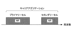
基地局装置1および端末装置2は、下りリンク、上りリンクおよび/またはサイドリンクにおいて、1つ以上のセルの集合を用いる通信をサポートできる。複数のセルの集合は、キャリアアグリゲーションまたはデュアルコネクティビティとも呼称される。キャリアアグリゲーションとデュアルコネクティビティの詳細は後述される。また、それぞれのセルは、所定の周波数帯域幅を用いる。所定の周波数帯域幅における最大値、最小値および設定可能な値は、予め規定できる。
The
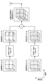
図1は、本実施形態におけるコンポーネントキャリアの設定の一例を示す図である。図1の例では、1つのLTEセルと2つのNRセルが設定される。1つのLTEセルは、プライマリーセルとして設定される。2つのNRセルは、それぞれプライマリーセカンダリーセルおよびセカンダリーセルとして設定される。2つのNRセルは、キャリアアグリゲーションにより統合される。また、LTEセルとNRセルは、デュアルコネクティビティにより統合される。なお、LTEセルとNRセルは、キャリアアグリゲーションにより統合されてもよい。図1の例では、NRは、プライマリーセルであるLTEセルにより接続をアシストされることが可能であるため、スタンドアロンで通信するための機能のような一部の機能をサポートしなくてもよい。スタンドアロンで通信するための機能は、初期接続に必要な機能を含む。 FIG. 1 is a diagram showing an example of setting a component carrier in the present embodiment. In the example of FIG. 1, one LTE cell and two NR cells are set. One LTE cell is set as the primary cell. The two NR cells are set as the primary secondary cell and the secondary cell, respectively. The two NR cells are integrated by carrier aggregation. In addition, LTE cells and NR cells are integrated by dual connectivity. The LTE cell and the NR cell may be integrated by carrier aggregation. In the example of FIG. 1, since the NR can be assisted by the LTE cell, which is the primary cell, it is not necessary to support some functions such as the function for communicating standalone. The functions for stand-alone communication include the functions required for the initial connection.
図2は、本実施形態におけるコンポーネントキャリアの設定の一例を示す図である。図2の例では、2つのNRセルが設定される。2つのNRセルは、それぞれプライマリーセルおよびセカンダリーセルとして設定され、キャリアアグリゲーションにより統合される。この場合、NRセルがスタンドアロンで通信するための機能をサポートすることにより、LTEセルのアシストが不要になる。なお、2つのNRセルは、デュアルコネクティビティにより統合されてもよい。 FIG. 2 is a diagram showing an example of setting the component carrier in the present embodiment. In the example of FIG. 2, two NR cells are set. The two NR cells are set as primary cells and secondary cells, respectively, and are integrated by carrier aggregation. In this case, by supporting the function for the NR cell to communicate standalone, the assist of the LTE cell becomes unnecessary. The two NR cells may be integrated by dual connectivity.
<本実施形態における無線フレーム構成>
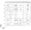
本実施形態において、10ms(ミリ秒)で構成される無線フレーム(radio frame)が規定される。無線フレームのそれぞれは2つのハーフフレームから構成される。ハーフフレームの時間間隔は、5msである。ハーフフレームのそれぞれは、5つのサブフレームから構成される。サブフレームの時間間隔は、1msであり、2つの連続するスロットによって定義される。スロットの時間間隔は、0.5msである。無線フレーム内のi番目のサブフレームは、(2×i)番目のスロットと(2×i+1)番目のスロットとから構成される。つまり、無線フレームのそれぞれにおいて、10個のサブフレームが規定される。
<Wireless frame configuration in this embodiment>
In this embodiment, a radio frame composed of 10 ms (milliseconds) is defined. Each radio frame consists of two half frames. The time interval of the half frame is 5 ms. Each half frame consists of five subframes. The subframe time interval is 1 ms and is defined by two consecutive slots. The slot time interval is 0.5 ms. The i-th subframe in the wireless frame is composed of the (2 × i) th slot and the (2 × i + 1) th slot. That is, 10 subframes are defined for each of the wireless frames.
サブフレームは、下りリンクサブフレーム、上りリンクサブフレーム、スペシャルサブフレームおよびサイドリンクサブフレームなどを含む。 Subframes include downlink subframes, uplink subframes, special subframes, sidelink subframes, and the like.
下りリンクサブフレームは下りリンク送信のために予約されるサブフレームである。上りリンクサブフレームは上りリンク送信のために予約されるサブフレームである。スペシャルサブフレームは3つのフィールドから構成される。3つのフィールドは、DwPTS(Downlink Pilot Time Slot)、GP(Guard Period)、およびUpPTS(Uplink Pilot Time Slot)を含む。DwPTS、GP、およびUpPTSの合計の長さは1msである。DwPTSは下りリンク送信のために予約されるフィールドである。UpPTSは上りリンク送信のために予約されるフィールドである。GPは下りリンク送信および上りリンク送信が行われないフィールドである。なお、スペシャルサブフレームは、DwPTSおよびGPのみによって構成されてもよいし、GPおよびUpPTSのみによって構成されてもよい。スペシャルサブフレームは、TDD(Time Division Duplex)において下りリンクサブフレームと上りリンクサブフレームとの間に配置され、下りリンクサブフレームから上りリンクサブフレームに切り替えるために用いられる。サイドリンクサブフレームは、サイドリンク通信のために予約または設定されるサブフレームである。サイドリンクは、端末装置間の近接直接通信および近接直接検出のために用いられる。 A downlink subframe is a subframe reserved for downlink transmission. An uplink subframe is a subframe reserved for uplink transmission. The special subframe consists of three fields. The three fields include DwPTS (Downlink Pilot Time Slot), GP (Guard Period), and UpPTS (Uplink Pilot Time Slot). The total length of DwPTS, GP, and UpPTS is 1 ms. DwPTS is a field reserved for downlink transmission. UpPTS is a field reserved for uplink transmission. GP is a field in which downlink transmission and uplink transmission are not performed. The special subframe may be composed of only DwPTS and GP, or may be composed of only GP and UpPTS. The special subframe is arranged between the downlink subframe and the uplink subframe in TDD (Time Division Duplex) and is used to switch from the downlink subframe to the uplink subframe. A sidelink subframe is a subframe reserved or set for sidelink communication. Sidelinks are used for proximity direct communication and proximity direct detection between terminal devices.
単一の無線フレームは、下りリンクサブフレーム、上りリンクサブフレーム、スペシャルサブフレームおよび/またはサイドリンクサブフレームから構成される。また、単一の無線フレームは、下りリンクサブフレーム、上りリンクサブフレーム、スペシャルサブフレームまたはサイドリンクサブフレームのみで構成されてもよい。
複数の無線フレーム構成がサポートされる。無線フレーム構成は、フレーム構成タイプで規定される。フレーム構成タイプ1は、FDD(Frequency Division Duplex)のみに適用できる。フレーム構成タイプ2は、TDDのみに適用できる。フレーム構成タイプ3は、LAA(Licensed Assisted Access)セカンダリーセルの運用のみに適用できる。
A single radio frame consists of downlink subframes, uplink subframes, special subframes and / or sidelink subframes. Further, a single radio frame may be composed of only a downlink subframe, an uplink subframe, a special subframe, or a side link subframe.
Multiple wireless frame configurations are supported. The wireless frame configuration is defined by the frame configuration type.
フレーム構成タイプ2において、複数の上りリンク−下りリンク構成が規定される。上りリンク−下りリンク構成において、1つの無線フレームにおける10のサブフレームのそれぞれは、下りリンクサブフレーム、上りリンクサブフレーム、およびスペシャルサブフレームのいずれかに対応する。サブフレーム0、サブフレーム5およびDwPTSは常に下りリンク送信のために予約される。UpPTSおよびそのスペシャルサブフレームの直後のサブフレームは常に上りリンク送信のために予約される。
In
フレーム構成タイプ3において、1つの無線フレーム内の10のサブフレームが下りリンク送信のために予約される。端末装置2は、PDSCHまたは検出信号が送信されないサブフレームを空のサブフレームとして扱うことができる。端末装置2は、所定の信号、チャネルおよび/または下りリンク送信があるサブフレームで検出されない限り、そのサブフレームにいかなる信号および/またはチャネルも存在しないと想定する。下りリンク送信は、1つまたは複数の連続したサブフレームで専有される。その下りリンク送信の最初のサブフレームは、そのサブフレーム内のどこからでも開始されてもよい。その下りリンク送信の最後のサブフレームは、完全に専有されるか、DwPTSで規定される時間間隔で専有されるか、のいずれかであってもよい。
In
なお、フレーム構成タイプ3において、1つの無線フレーム内の10のサブフレームが上りリンク送信のために予約されてもよい。また、1つの無線フレーム内の10のサブフレームのそれぞれが、下りリンクサブフレーム、上りリンクサブフレーム、スペシャルサブフレームおよびサイドリンクサブフレームのいずれかに対応するようにしてもよい。
In the
基地局装置1は、スペシャルサブフレームのDwPTSにおいて、下りリンク物理チャネルおよび下りリンク物理信号を送信してもよい。基地局装置1は、スペシャルサブフレームのDwPTSにおいて、PBCHの送信を制限できる。端末装置2は、スペシャルサブフレームのUpPTSにおいて、上りリンク物理チャネルおよび上りリンク物理信号を送信してもよい。端末装置2は、スペシャルサブフレームのUpPTSにおいて、一部の上りリンク物理チャネルおよび上りリンク物理信号の送信を制限できる。
The
なお、1つの送信における時間間隔はTTI(Transmission Time Interval)と呼称され、LTEにおいて、1ms(1サブフレーム)を1TTIと定義される。 The time interval in one transmission is called TTI (Transmission Time Interval), and 1 ms (1 subframe) is defined as 1 TTI in LTE.
<本実施形態におけるLTEのフレーム構成>
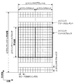
図3は、本実施形態におけるLTEの下りリンクサブフレームの一例を示す図である。図3に示される図は、LTEの下りリンクリソースグリッドとも呼称される。基地局装置1は、端末装置2への下りリンクサブフレームにおいて、LTEの下りリンク物理チャネルおよび/またはLTEの下りリンク物理信号を送信できる。端末装置2は、基地局装置1からの下りリンクサブフレームにおいて、LTEの下りリンク物理チャネルおよび/またはLTEの下りリンク物理信号を受信できる。
<LTE frame configuration in this embodiment>
FIG. 3 is a diagram showing an example of the LTE downlink subframe in the present embodiment. The figure shown in FIG. 3 is also referred to as an LTE downlink resource grid. The
図4は、本実施形態におけるLTEの上りリンクサブフレームの一例を示す図である。図4に示される図は、LTEの上りリンクリソースグリッドとも呼称される。端末装置2は、基地局装置1への上りリンクサブフレームにおいて、LTEの上りリンク物理チャネルおよび/またはLTEの上りリンク物理信号を送信できる。基地局装置1は、端末装置2からの上りリンクサブフレームにおいて、LTEの上りリンク物理チャネルおよび/またはLTEの上りリンク物理信号を受信できる。
FIG. 4 is a diagram showing an example of the LTE uplink subframe in the present embodiment. The figure shown in FIG. 4 is also referred to as an LTE uplink resource grid. The
本実施形態において、LTEの物理リソースは以下のように定義されうる。1つのスロットは複数のシンボルによって定義される。スロットのそれぞれにおいて送信される物理信号または物理チャネルは、リソースグリッドによって表現される。下りリンクにおいて、リソースグリッドは、周波数方向に対する複数のサブキャリアと、時間方向に対する複数のOFDMシンボルによって定義される。上りリンクにおいて、リソースグリッドは、周波数方向に対する複数のサブキャリアと、時間方向に対する複数のSC−FDMAシンボルによって定義される。サブキャリアまたはリソースブロックの数は、セルの帯域幅に依存して決まるようにしてもよい。1つのスロットにおけるシンボルの数は、CP(Cyclic Prefix)のタイプによって決まる。CPのタイプは、ノーマルCPまたは拡張CPである。ノーマルCPにおいて、1つのスロットを構成するOFDMシンボルまたはSC−FDMAシンボルの数は7である。拡張CPにおいて、1つのスロットを構成するOFDMシンボルまたはSC−FDMAシンボルの数は6である。リソースグリッド内のエレメントのそれぞれはリソースエレメントと称される。リソースエレメントは、サブキャリアのインデックス(番号)とシンボルのインデックス(番号)とを用いて識別される。なお、本実施形態の説明において、OFDMシンボルまたはSC−FDMAシンボルは単にシンボルとも呼称される。 In this embodiment, LTE physical resources can be defined as follows. A slot is defined by a plurality of symbols. The physical signal or channel transmitted in each of the slots is represented by a resource grid. On the downlink, the resource grid is defined by multiple subcarriers in the frequency direction and multiple OFDM symbols in the time direction. In the uplink, the resource grid is defined by a plurality of subcarriers in the frequency direction and a plurality of SC-FDMA symbols in the time direction. The number of subcarriers or resource blocks may depend on the bandwidth of the cell. The number of symbols in one slot is determined by the type of CP (Cyclic Prefix). The type of CP is normal CP or extended CP. In normal CP, the number of OFDM symbols or SC-FDMA symbols constituting one slot is 7. In the expansion CP, the number of OFDM symbols or SC-FDMA symbols constituting one slot is 6. Each of the elements in the resource grid is called a resource element. Resource elements are identified using the subcarrier index (number) and the symbol index (number). In the description of this embodiment, the OFDM symbol or the SC-FDMA symbol is also simply referred to as a symbol.
リソースブロックは、ある物理チャネル(PDSCHまたはPUSCHなど)をリソースエレメントにマッピングするために用いられる。リソースブロックは、仮想リソースブロックと物理リソースブロックを含む。ある物理チャネルは、仮想リソースブロックにマッピングされる。仮想リソースブロックは、物理リソースブロックにマッピングされる。1つの物理リソースブロックは、時間領域において所定数の連続するシンボルで定義される。1つの物理リソースブロックは、周波数領域において所定数の連続するサブキャリアとから定義される。1つの物理リソースブロックにおけるシンボル数およびサブキャリア数は、そのセルにおけるCPのタイプ、サブキャリア間隔および/または上位層によって設定されるパラメータなどに基づいて決まる。例えば、CPのタイプがノーマルCPであり、サブキャリア間隔が15kHzである場合、1つの物理リソースブロックにおけるシンボル数は7であり、サブキャリア数は12である。その場合、1つの物理リソースブロックは(7×12)個のリソースエレメントから構成される。物理リソースブロックは周波数領域において0から番号が付けられる。また、同一の物理リソースブロック番号が対応する、1つのサブフレーム内の2つのリソースブロックは、物理リソースブロックペア(PRBペア、RBペア)として定義される。 Resource blocks are used to map a physical channel (such as PDSCH or PUSCH) to a resource element. The resource block includes a virtual resource block and a physical resource block. A physical channel is mapped to a virtual resource block. Virtual resource blocks are mapped to physical resource blocks. One physical resource block is defined by a predetermined number of consecutive symbols in the time domain. One physical resource block is defined from a predetermined number of contiguous subcarriers in the frequency domain. The number of symbols and the number of subcarriers in one physical resource block is determined based on the type of CP in the cell, the subcarrier interval and / or the parameters set by the upper layer and the like. For example, when the CP type is normal CP and the subcarrier interval is 15 kHz, the number of symbols in one physical resource block is 7, and the number of subcarriers is 12. In that case, one physical resource block is composed of (7 × 12) resource elements. Physical resource blocks are numbered from 0 in the frequency domain. Further, two resource blocks in one subframe corresponding to the same physical resource block number are defined as a physical resource block pair (PRB pair, RB pair).
LTEセルのそれぞれにおいて、あるサブフレームでは、1つの所定のパラメータが用いられる。例えば、その所定のパラメータは、送信信号に関するパラメータ(物理パラメータ)である。送信信号に関するパラメータは、CP長、サブキャリア間隔、1つのサブフレーム(所定の時間長)におけるシンボル数、1つのリソースブロック(所定の周波数帯域)のおけるサブキャリア数、多元接続方式、および、信号波形などを含む。 In each of the LTE cells, one predetermined parameter is used in a certain subframe. For example, the predetermined parameter is a parameter (physical parameter) relating to a transmission signal. The parameters related to the transmission signal are CP length, subcarrier interval, number of symbols in one subframe (predetermined time length), number of subcarriers in one resource block (predetermined frequency band), multiple access method, and signal. Includes waveforms, etc.
すなわち、LTEセルでは、下りリンク信号および上りリンク信号は、それぞれ所定の時間長(例えば、サブフレーム)において、1つの所定のパラメータを用いて生成される。換言すると、端末装置2は、基地局装置1から送信される下りリンク信号、および、基地局装置1に送信する上りリンク信号が、それぞれ所定の時間長において、1つの所定のパラメータで生成される、と想定する。また、基地局装置1は、端末装置2に送信する下りリンク信号、および、端末装置2から送信される上りリンク信号が、それぞれ所定の時間長において、1つの所定のパラメータで生成されるように設定する。
That is, in the LTE cell, the downlink signal and the uplink signal are each generated for a predetermined time length (for example, a subframe) using one predetermined parameter. In other words, in the
<本実施形態におけるNRのフレーム構成>
NRセルのそれぞれにおいて、ある所定の時間長(例えば、サブフレーム)では、1つ以上の所定のパラメータが用いられる。すなわち、NRセルでは、下りリンク信号および上りリンク信号は、それぞれ所定の時間長において、1つ以上の所定のパラメータを用いて生成される。換言すると、端末装置2は、基地局装置1から送信される下りリンク信号、および、基地局装置1に送信する上りリンク信号が、それぞれ所定の時間長において、1つ以上の所定のパラメータで生成される、と想定する。また、基地局装置1は、端末装置2に送信する下りリンク信号、および、端末装置2から送信される上りリンク信号が、それぞれ所定の時間長において、1つ以上の所定のパラメータで生成されるように設定できる。複数の所定のパラメータが用いられる場合、それらの所定のパラメータが用いられて生成される信号は、所定の方法により多重される。例えば、所定の方法は、FDM(Frequency Division Multiplexing)、TDM(Time Division Multiplexing)、CDM(Code Division Multiplexing)および/またはSDM(Spatial Division Multiplexing)などを含む。
<Frame configuration of NR in this embodiment>
In each of the NR cells, one or more predetermined parameters are used for a given time length (eg, subframe). That is, in the NR cell, the downlink signal and the uplink signal are each generated for a predetermined time length using one or more predetermined parameters. In other words, in the
NRセルに設定される所定のパラメータの組み合わせは、パラメータセットとして、複数種類を予め規定できる。 A plurality of types of predetermined parameter combinations set in the NR cell can be defined in advance as a parameter set.
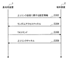
図5は、NRセルにおける送信信号に関するパラメータセットの一例を示す図である。図5の例では、パラメータセットに含まれる送信信号に関するパラメータは、サブキャリア間隔、NRセルにおけるリソースブロックあたりのサブキャリア数、サブフレームあたりのシンボル数、および、CP長タイプである。CP長タイプは、NRセルで用いられるCP長のタイプである。例えば、CP長タイプ1はLTEにおけるノーマルCPに相当し、CP長タイプ2はLTEにおける拡張CPに相当する。
FIG. 5 is a diagram showing an example of a parameter set relating to a transmission signal in the NR cell. In the example of FIG. 5, the parameters related to the transmission signal included in the parameter set are the subcarrier interval, the number of subcarriers per resource block in the NR cell, the number of symbols per subframe, and the CP length type. The CP length type is the type of CP length used in the NR cell. For example,
NRセルにおける送信信号に関するパラメータセットは、下りリンクおよび上りリンクでそれぞれ個別に規定することができる。また、NRセルにおける送信信号に関するパラメータセットは、下りリンクおよび上りリンクでそれぞれ独立に設定できる。 The parameter set for the transmission signal in the NR cell can be specified individually for the downlink and the uplink, respectively. Further, the parameter set related to the transmission signal in the NR cell can be set independently for the downlink and the uplink.
図6は、本実施形態におけるNRの下りリンクサブフレームの一例を示す図である。図6の例では、パラメータセット1、パラメータセット0およびパラメータセット2を用いて生成される信号が、セル(システム帯域幅)において、FDMされる。図6に示される図は、NRの下りリンクリソースグリッドとも呼称される。基地局装置1は、端末装置2への下りリンクサブフレームにおいて、NRの下りリンク物理チャネルおよび/またはNRの下りリンク物理信号を送信できる。端末装置2は、基地局装置1からの下りリンクサブフレームにおいて、NRの下りリンク物理チャネルおよび/またはNRの下りリンク物理信号を受信できる。
FIG. 6 is a diagram showing an example of a downlink subframe of NR in the present embodiment. In the example of FIG. 6, the signals generated using parameter set 1, parameter set 0 and parameter set 2 are FDMed in the cell (system bandwidth). The figure shown in FIG. 6 is also referred to as an NR downlink resource grid. The
図7は、本実施形態におけるNRの上りリンクサブフレームの一例を示す図である。図7の例では、パラメータセット1、パラメータセット0およびパラメータセット2を用いて生成される信号が、セル(システム帯域幅)において、FDMされる。図6に示される図は、NRの上りリンクリソースグリッドとも呼称される。基地局装置1は、端末装置2への上りリンクサブフレームにおいて、NRの上りリンク物理チャネルおよび/またはNRの上りリンク物理信号を送信できる。端末装置2は、基地局装置1からの上りリンクサブフレームにおいて、NRの上りリンク物理チャネルおよび/またはNRの上りリンク物理信号を受信できる。
FIG. 7 is a diagram showing an example of an uplink subframe of NR in the present embodiment. In the example of FIG. 7, the signals generated using parameter set 1, parameter set 0 and parameter set 2 are FDMed in the cell (system bandwidth). The figure shown in FIG. 6 is also referred to as an NR uplink resource grid. The
<本実施形態におけるアンテナポート>
アンテナポートは、あるシンボルを運ぶ伝搬チャネルが、同一のアンテナポートにおける別のシンボルを運ぶ伝搬チャネルから推測できるようにするために定義される。例えば、同一のアンテナポートにおける異なる物理リソースは、同一の伝搬チャネルで送信されていると想定できる。すなわち、あるアンテナポートにおけるシンボルは、そのアンテナポートにおける参照信号により伝搬チャネルを推定し、復調することができる。また、アンテナポート毎に1つのリソースグリッドがある。アンテナポートは、参照信号によって定義される。また、それぞれの参照信号は、複数のアンテナポートを定義できる。
<Antenna port in this embodiment>
Antenna ports are defined so that a propagation channel carrying one symbol can be inferred from a propagation channel carrying another symbol on the same antenna port. For example, it can be assumed that different physical resources on the same antenna port are transmitted on the same propagation channel. That is, a symbol at an antenna port can be demodulated by estimating the propagation channel from the reference signal at that antenna port. There is also one resource grid for each antenna port. The antenna port is defined by the reference signal. Also, each reference signal can define multiple antenna ports.
アンテナポートはアンテナポート番号によって特定または識別される。例えば、アンテナポート0〜3は、CRSが送信されるアンテナポートである。すなわち、アンテナポート0〜3で送信されるPDSCHは、アンテナポート0〜3に対応するCRSで復調できる。
Antenna ports are identified or identified by antenna port number. For example,
2つのアンテナポートは所定の条件を満たす場合、準同一位置(QCL:Quasi co-location)であると表すことができる。その所定の条件は、あるアンテナポートにおけるシンボルを運ぶ伝搬チャネルの広域的特性が、別のアンテナポートにおけるシンボルを運ぶ伝搬チャネルから推測できることである。広域的特性は、遅延分散、ドップラースプレッド、ドップラーシフト、平均利得および/または平均遅延を含む。 The two antenna ports can be expressed as having a quasi-co-location (QCL) if a predetermined condition is satisfied. The predetermined condition is that the wide-area characteristics of the propagation channel carrying the symbol at one antenna port can be inferred from the propagation channel carrying the symbol at another antenna port. Wide-area characteristics include delay variance, Doppler spread, Doppler shift, average gain and / or average delay.
本実施形態において、アンテナポート番号は、RAT毎に異なって定義されてもよいし、RAT間で共通に定義されてもよい。例えば、LTEにおけるアンテナポート0〜3は、CRSが送信されるアンテナポートである。NRにおいて、アンテナポート0〜3は、LTEと同様のCRSが送信されるアンテナポートとすることができる。また、NRにおいて、LTEと同様のCRSが送信されるアンテナポートは、アンテナポート0〜3とは異なるアンテナポート番号とすることができる。本実施形態の説明において、所定のアンテナポート番号は、LTEおよび/またはNRに対して適用できる。
In the present embodiment, the antenna port number may be defined differently for each RAT, or may be commonly defined among the RATs. For example,
<本実施形態における物理チャネルおよび物理信号>
本実施形態において、物理チャネルおよび物理信号が用いられる。
<Physical channel and physical signal in this embodiment>
In this embodiment, physical channels and physical signals are used.
物理チャネルは、下りリンク物理チャネル、上りリンク物理チャネルおよびサイドリンク物理チャネルを含む。物理信号は、下りリンク物理信号、上りリンク物理信号およびサイドリンク物理信号を含む。 Physical channels include downlink physical channels, uplink physical channels, and sidelink physical channels. Physical signals include downlink physical signals, uplink physical signals and side link physical signals.
LTEにおける物理チャネルおよび物理信号は、それぞれLTE物理チャネルおよびLTE物理信号とも呼称される。NRにおける物理チャネルおよび物理信号は、それぞれNR物理チャネルおよびNR物理信号とも呼称される。LTE物理チャネルおよびNR物理チャネルは、それぞれ異なる物理チャネルとして定義できる。LTE物理信号およびNR物理信号は、それぞれ異なる物理信号として定義できる。本実施形態の説明において、LTE物理チャネルおよびNR物理チャネルは単に物理チャネルとも呼称され、LTE物理信号およびNR物理信号は単に物理信号とも呼称される。すなわち、物理チャネルに対する説明は、LTE物理チャネルおよびNR物理チャネルのいずれに対しても適用できる。物理信号に対する説明は、LTE物理信号およびNR物理信号のいずれに対しても適用できる。 Physical channels and physical signals in LTE are also referred to as LTE physical channels and LTE physical signals, respectively. The physical channel and physical signal in NR are also referred to as NR physical channel and NR physical signal, respectively. The LTE physical channel and the NR physical channel can be defined as different physical channels. The LTE physical signal and the NR physical signal can be defined as different physical signals. In the description of this embodiment, the LTE physical channel and the NR physical channel are also referred to simply as physical channels, and the LTE physical signal and the NR physical signal are also simply referred to as physical signals. That is, the description for physical channels can be applied to both LTE and NR physical channels. The description for physical signals can be applied to both LTE and NR physical signals.
<本実施形態におけるNR物理チャネルおよびNR物理信号>
LTEにおける物理チャネルおよび物理信号に対する説明は、それぞれNR物理チャネルおよびNR物理信号に対しても適用できる。NR物理チャネルおよびNR物理信号は、以下のように呼称される。
<NR physical channel and NR physical signal in this embodiment>
The description for physical channels and signals in LTE also applies to NR physical channels and NR physical signals, respectively. The NR physical channel and the NR physical signal are referred to as follows.
NR下りリンク物理チャネルは、NR−PBCH、NR−PCFICH、NR−PHICH、NR−PDCCH、NR−EPDCCH、NR−MPDCCH、NR−R−PDCCH、NR−PDSCH、および、NR−PMCHなどを含む。 The NR downlink physical channel includes NR-PBCH, NR-PCFICH, NR-PHICH, NR-PDCCH, NR-EPDCCH, NR-MPDCCH, NR-R-PDCCH, NR-PDSCH, NR-PMCH, and the like.
NR下りリンク物理信号は、NR−SS、NR−DL−RSおよびNR−DSなどを含む。NR−SSは、NR−PSSおよびNR−SSSなどを含む。NR−RSは、NR−CRS、NR−PDSCH−DMRS、NR−EPDCCH−DMRS、NR−PRS、NR−CSI−RS、およびNR−TRSなどを含む。 The NR downlink physical signal includes NR-SS, NR-DL-RS, NR-DS and the like. NR-SS includes NR-PSS, NR-SSS and the like. NR-RS includes NR-CRS, NR-PDSCH-DMRS, NR-EPDCCH-DMRS, NR-PRS, NR-CSI-RS, NR-TRS and the like.
NR上りリンク物理チャネルは、NR−PUSCH、NR−PUCCH、およびNR−PRACHなどを含む。 NR uplink physical channels include NR-PUSCH, NR-PUCCH, NR-PRACH, and the like.
NR上りリンク物理信号は、NR−UL−RSを含む。NR−UL−RSは、NR−UL−DMRSおよびNR−SRSなどを含む。 The NR uplink physical signal includes NR-UL-RS. NR-UL-RS includes NR-UL-DMRS, NR-SRS and the like.
NRサイドリンク物理チャネルは、NR−PSBCH、NR−PSCCH、NR−PSDCH、およびNR−PSSCHなどを含む。 NR side-link physical channels include NR-PSBCH, NR-PSCCH, NR-PSDCH, NR-PSSCH and the like.
<本実施形態における下りリンク物理チャネル>
PBCHは、基地局装置1のサービングセルに固有の報知情報であるMIB(Master Information Block)を報知するために用いられる。PBCHは無線フレーム内のサブフレーム0のみで送信される。MIBは、40ms間隔で更新できる。PBCHは10ms周期で繰り返し送信される。具体的には、SFN(System Frame Number)を4で割った余りが0である条件を満たす無線フレームにおけるサブフレーム0においてMIBの初期送信が行なわれ、他の全ての無線フレームにおけるサブフレーム0においてMIBの再送信(repetition)が行われる。SFNは無線フレームの番号(システムフレーム番号)である。MIBはシステム情報である。例えば、MIBは、SFNを示す情報を含む。
<Downlink physical channel in this embodiment>
The PBCH is used to notify the MIB (Master Information Block), which is the notification information unique to the serving cell of the
PHICHは、基地局装置1が受信した上りリンクデータ(Uplink Shared Channel: UL-SCH)に対するACK(ACKnowledgement)またはNACK(Negative ACKnowledgement)を示すHARQ−ACK(HARQインディケータ、HARQフィードバック、応答情報)を送信するために用いられる。例えば、端末装置2がACKを示すHARQ−ACKを受信した場合は、対応する上りリンクデータを再送しない。例えば、端末装置2がNACKを示すHARQ−ACKを受信した場合は、端末装置2は対応する上りリンクデータを所定の上りリンクサブフレームで再送する。あるPHICHは、ある上りリンクデータに対するHARQ−ACKを送信する。基地局装置1は、同一のPUSCHに含まれる複数の上りリンクデータに対するHARQ−ACKのそれぞれを複数のPHICHを用いて送信する。
PHICH transmits HARQ-ACK (HARQ indicator, HARQ feedback, response information) indicating ACK (ACKnowledgement) or NACK (Negative ACKnowledgement) for the uplink data (Uplink Shared Channel: UL-SCH) received by the
PDCCHおよびEPDCCHは、下りリンク制御情報(Downlink Control Information: DCI)を送信するために用いられる。下りリンク制御情報の情報ビットのマッピングが、DCIフォーマットとして定義される。下りリンク制御情報は、下りリンクグラント(downlink grant)および上りリンクグラント(uplink grant)を含む。下りリンクグラントは、下りリンクアサインメント(downlink assignment)または下りリンク割り当て(downlink allocation)とも称する。 PDCCH and EPDCCH are used to transmit Downlink Control Information (DCI). The mapping of the information bits of the downlink control information is defined as the DCI format. The downlink control information includes a downlink grant and an uplink grant. Downlink grants are also referred to as downlink assignments or downlink allocations.
PDCCHは、連続する1つまたは複数のCCE(Control Channel Element)の集合によって送信される。CCEは、9つのREG(Resource Element Group)で構成される。REGは、4つのリソースエレメントで構成される。PDCCHがn個の連続するCCEで構成される場合、そのPDCCHは、CCEのインデックス(番号)であるiをnで割った余りが0である条件を満たすCCEから始まる。 The PDCCH is transmitted by a set of one or more consecutive CCEs (Control Channel Elements). CCE is composed of 9 REGs (Resource Element Groups). The REG is composed of four resource elements. When the PDCCH is composed of n consecutive CCEs, the PDCCH starts from the CCE satisfying the condition that the remainder of dividing i, which is the index (number) of the CCE, by n is 0.
EPDCCHは、連続する1つまたは複数のECCE(Enhanced Control Channel Element)の集合によって送信される。ECCEは、複数のEREG(Enhanced Resource Element Group)で構成される。 The EPDCCH is transmitted by a set of one or more consecutive ECCEs (Enhanced Control Channel Elements). ECCE is composed of a plurality of EREGs (Enhanced Resource Element Groups).
下りリンクグラントは、あるセル内のPDSCHのスケジューリングに用いられる。下りリンクグラントは、その下りリンクグラントが送信されたサブフレームと同じサブフレーム内のPDSCHのスケジューリングに用いられる。上りリンクグラントは、あるセル内のPUSCHのスケジューリングに用いられる。上りリンクグラントは、その上りリンクグラントが送信されたサブフレームより4つ以上後のサブフレーム内の単一のPUSCHのスケジューリングに用いられる。 The downlink grant is used for scheduling PDSCH in a cell. The downlink grant is used to schedule the PDSCH in the same subframe as the subframe in which the downlink grant was transmitted. Uplink grants are used to schedule PUSCH within a cell. The uplink grant is used to schedule a single PUSCH in a subframe four or more later than the subframe in which the uplink grant was transmitted.
DCIには、CRC(Cyclic Redundancy Check)パリティビットが付加される。CRCパリティビットは、RNTI(Radio Network Temporary Identifier)でスクランブルされる。RNTIは、DCIの目的などに応じて、規定または設定できる識別子である。RNTIは、仕様で予め規定される識別子、セルに固有の情報として設定される識別子、端末装置2に固有の情報として設定される識別子、または、端末装置2に属するグループに固有の情報として設定される識別子である。例えば、端末装置2は、PDCCHまたはEPDCCHのモニタリングにおいて、DCIに付加されたCRCパリティビットに所定のRNTIでデスクランブルし、CRCが正しいかどうかを識別する。CRCが正しい場合、そのDCIは端末装置2のためのDCIであることが分かる。
A CRC (Cyclic Redundancy Check) parity bit is added to the DCI. The CRC parity bit is scrambled by RNTI (Radio Network Temporary Identifier). RNTI is an identifier that can be specified or set according to the purpose of DCI and the like. RNTI is set as an identifier defined in advance in the specifications, an identifier set as cell-specific information, an identifier set as terminal device 2-specific information, or information unique to a group belonging to the
PDSCHは、下りリンクデータ(Downlink Shared Channel: DL-SCH)を送信するために用いられる。また、PDSCHは、上位層の制御情報を送信するためにも用いられる。 The PDSCH is used to transmit downlink data (Downlink Shared Channel: DL-SCH). The PDSCH is also used to transmit control information of the upper layer.
PMCHは、マルチキャストデータ(Multicast Channel: MCH)を送信するために用いられる。 PMCH is used to transmit multicast data (Multicast Channel: MCH).
PDCCH領域において、複数のPDCCHが周波数、時間、および/または、空間多重されてもよい。EPDCCH領域において、複数のEPDCCHが周波数、時間、および/または、空間多重されてもよい。PDSCH領域において、複数のPDSCHが周波数、時間、および/または、空間多重されてもよい。PDCCH、PDSCHおよび/またはEPDCCHは周波数、時間、および/または、空間多重されてもよい。 In the PDCCH region, multiple PDCCHs may be frequency, temporal, and / or spatially multiplexed. In the EPDCCH region, multiple EPDCCHs may be frequency, temporal, and / or spatially multiplexed. In the PDSCH region, multiple PDSCHs may be frequency, time, and / or spatially multiplexed. PDCCH, PDSCH and / or EPDCCH may be frequency, temporal, and / or spatially multiplexed.
<本実施形態における下りリンク物理信号>
PDSCHは、送信モードおよびDCIフォーマットに基づいて、CRSまたはURSの送信に用いられるアンテナポートで送信される。DCIフォーマット1Aは、CRSの送信に用いられるアンテナポートで送信されるPDSCHのスケジューリングに用いられる。DCIフォーマット2Dは、URSの送信に用いられるアンテナポートで送信されるPDSCHのスケジューリングに用いられる。
<Downlink physical signal in this embodiment>
The PDSCH is transmitted at the antenna port used for CRS or URS transmission based on the transmission mode and DCI format. DCI format 1A is used for scheduling PDSCH transmitted at the antenna port used for CRS transmission. DCI format 2D is used for scheduling PDSCH transmitted at the antenna port used for URS transmission.
EPDCCHに関連するDMRSは、DMRSが関連するEPDCCHの送信に用いられるサブフレームおよび帯域で送信される。DMRSは、DMRSが関連するEPDCCHの復調を行なうために用いられる。EPDCCHは、DMRSの送信に用いられるアンテナポートで送信される。EPDCCHに関連するDMRSは、アンテナポート107〜114の1つまたは複数で送信される。 The EPDCCH-related DMRS is transmitted in the subframes and bands used by the DMRS to transmit the EPDCCH associated. DMRS is used to demodulate the EPDCCH associated with DMRS. The EPDCCH is transmitted at the antenna port used to transmit the DMRS. The DMRS associated with EPDCCH is transmitted on one or more of antenna ports 107-114.
<本実施形態における上りリンク物理チャネル>
PUCCHは、上りリンク制御情報(Uplink Control Information: UCI)を送信するために用いられる物理チャネルである。上りリンク制御情報は、下りリンクのチャネル状態情報(Channel State Information: CSI)、PUSCHリソースの要求を示すスケジューリング要求(Scheduling Request: SR)、下りリンクデータ(Transport block: TB, Downlink-Shared Channel: DL-SCH)に対するHARQ−ACKを含む。HARQ−ACKは、ACK/NACK、HARQフィードバック、または、応答情報とも称される。また、下りリンクデータに対するHARQ−ACKは、ACK、NACK、またはDTXを示す。
<Uplink physical channel in this embodiment>
PUCCH is a physical channel used to transmit Uplink Control Information (UCI). The uplink control information includes downlink channel state information (CSI), scheduling request indicating a PUSCH resource request (SR), and downlink data (Transport block: TB, Downlink-Shared Channel: DL). -Includes HARQ-ACK for SCH). HARQ-ACK is also referred to as ACK / NACK, HARQ feedback, or response information. Further, HARQ-ACK for downlink data indicates ACK, NACK, or DTX.
PUSCHは、上りリンクデータ(Uplink-Shared Channel: UL-SCH)を送信するために用いられる物理チャネルである。また、PUSCHは、上りリンクデータと共にHARQ−ACKおよび/またはチャネル状態情報を送信するために用いられてもよい。また、PUSCHは、チャネル状態情報のみ、または、HARQ−ACKおよびチャネル状態情報のみを送信するために用いられてもよい。 PUSCH is a physical channel used to transmit uplink data (Uplink-Shared Channel: UL-SCH). The PUSCH may also be used to transmit HARQ-ACK and / or channel state information along with uplink data. In addition, PUSCH may be used to transmit only channel state information, or only HARQ-ACK and channel state information.
PRACHは、ランダムアクセスプリアンブルを送信するために用いられる物理チャネルである。PRACHは、端末装置2が基地局装置1と時間領域の同期をとるために用いられることができる。また、PRACHは、初期コネクション構築(initial connection establishment)手続き(処理)、ハンドオーバ手続き、コネクション再構築(connection re-establishment)手続き、上りリンク送信に対する同期(タイミング調整)、および/または、PUSCHリソースの要求を示すためにも用いられる。
The PRACH is a physical channel used to transmit a random access preamble. The PRACH can be used by the
PUCCH領域において、複数のPUCCHが周波数、時間、空間および/またはコード多重される。PUSCH領域において、複数のPUSCHが周波数、時間、空間および/またはコード多重されてもよい。PUCCHおよびPUSCHは周波数、時間、空間および/またはコード多重されてもよい。PRACHは単一のサブフレームまたは2つのサブフレームにわたって配置されてもよい。複数のPRACHが符号多重されてもよい。 In the PUCCH region, multiple PUCCHs are frequency, temporal, spatial and / or code-multiplexed. In the PUSCH region, multiple PUSCHs may be frequency, temporal, spatial and / or code-multiplexed. PUCCH and PUSCH may be frequency, temporal, spatial and / or code-multiplexed. The PRACH may be located over a single subframe or two subframes. A plurality of PRACHs may be code-multiplexed.
<本実施形態における基地局装置1の構成例>
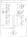
図8は、本実施形態の基地局装置1の構成を示す概略ブロック図である。図示するように、基地局装置1は、上位層処理部101、制御部103、受信部105、送信部107、および、送受信アンテナ109、を含んで構成される。また、受信部105は、復号化部1051、復調部1053、多重分離部1055、無線受信部1057、およびチャネル測定部1059を含んで構成される。また、送信部107は、符号化部1071、変調部1073、多重部1075、無線送信部1077、および下りリンク参照信号生成部1079を含んで構成される。
<Structure example of
FIG. 8 is a schematic block diagram showing the configuration of the
既に説明したように、基地局装置1は、1つ以上のRATをサポートできる。図8に示す基地局装置1に含まれる各部の一部または全部は、RATに応じて個別に構成されうる。例えば、受信部105および送信部107は、LTEとNRとで個別に構成される。また、NRセルにおいて、図8に示す基地局装置1に含まれる各部の一部または全部は、送信信号に関するパラメータセットに応じて個別に構成されうる。例えば、あるNRセルにおいて、無線受信部1057および無線送信部1077は、送信信号に関するパラメータセットに応じて個別に構成されうる。
As described above, the
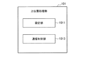
上位層処理部101は、媒体アクセス制御(MAC: Medium Access Control)層、パケットデータ統合プロトコル(Packet Data Convergence Protocol: PDCP)層、無線リンク制御(Radio Link Control: RLC)層、無線リソース制御(Radio Resource Control: RRC)層の処理を行う。また、上位層処理部101は、受信部105、および送信部107の制御を行うために制御情報を生成し、制御部103に出力する。
The upper
制御部103は、上位層処理部101からの制御情報に基づいて、受信部105および送信部107の制御を行う。制御部103は、上位層処理部101への制御情報を生成し、上位層処理部101に出力する。制御部103は、復号化部1051からの復号化された信号およびチャネル測定部1059からのチャネル推定結果を入力する。制御部103は、符号化する信号を符号化部1071へ出力する。また、制御部103は、基地局装置1の全体または一部を制御するために用いられる。
The
上位層処理部101は、RAT制御、無線リソース制御、サブフレーム設定、スケジューリング制御、および/または、CSI報告制御に関する処理および管理を行う。上位層処理部101における処理および管理は、端末装置毎、または基地局装置に接続している端末装置共通に行われる。上位層処理部101における処理および管理は、上位層処理部101のみで行われてもよいし、上位ノードまたは他の基地局装置から取得してもよい。また、上位層処理部101における処理および管理は、RATに応じて個別に行われてもよい。例えば、上位層処理部101は、LTEにおける処理および管理と、NRにおける処理および管理とを個別に行う。
The upper
上位層処理部101におけるRAT制御では、RATに関する管理が行われる。例えば、RAT制御では、LTEに関する管理および/またはNRに関する管理が行われる。NRに関する管理は、NRセルにおける送信信号に関するパラメータセットの設定および処理を含む。
In the RAT control in the upper
上位層処理部101における無線リソース制御では、下りリンクデータ(トランスポートブロック)、システムインフォメーション、RRCメッセージ(RRCパラメータ)、および/または、MAC制御エレメント(CE:Control Element)の生成および/または管理が行われる。
In the radio resource control in the upper
上位層処理部101におけるサブフレーム設定では、サブフレーム設定、サブフレームパターン設定、上りリンク−下りリンク設定、上りリンク参照UL−DL設定、および/または、下りリンク参照UL−DL設定の管理が行われる。なお、上位層処理部101におけるサブフレーム設定は、基地局サブフレーム設定とも呼称される。また、上位層処理部101におけるサブフレーム設定は、上りリンクのトラフィック量および下りリンクのトラフィック量に基づいて決定できる。また、上位層処理部101におけるサブフレーム設定は、上位層処理部101におけるスケジューリング制御のスケジューリング結果に基づいて決定できる。
In the subframe setting in the upper
上位層処理部101におけるスケジューリング制御では、受信したチャネル状態情報およびチャネル測定部1059から入力された伝搬路の推定値やチャネルの品質などに基づいて、物理チャネルを割り当てる周波数およびサブフレーム、物理チャネルの符号化率および変調方式および送信電力などが決定される。例えば、制御部103は、上位層処理部101におけるスケジューリング制御のスケジューリング結果に基づいて、制御情報(DCIフォーマット)を生成する。
In the scheduling control in the upper
上位層処理部101におけるCSI報告制御では、端末装置2のCSI報告が制御される。例えば、端末装置2においてCSIを算出するために想定するためのCSI参照リソースに関する設定が制御される。
In the CSI report control in the upper
受信部105は、制御部103からの制御に従って、送受信アンテナ109を介して端末装置2から送信された信号を受信し、さらに分離、復調、復号などの受信処理を行い、受信処理された情報を制御部103に出力する。なお、受信部105における受信処理は、あらかじめ規定された設定、または基地局装置1が端末装置2に通知した設定に基づいて行われる。
The receiving
無線受信部1057は、送受信アンテナ109を介して受信された上りリンクの信号に対して、中間周波数への変換(ダウンコンバート)、不要な周波数成分の除去、信号レベルが適切に維持されるように増幅レベルの制御、受信された信号の同相成分および直交成分に基づく直交復調、アナログ信号からディジタル信号への変換、ガードインターバル(Guard Interval: GI)の除去、および/または、高速フーリエ変換(Fast Fourier Transform: FFT)による周波数領域信号の抽出を行う。
The radio receiver 1057 converts the uplink signal received via the transmission /
多重分離部1055は、無線受信部1057から入力された信号から、PUCCHまたはPUSCHなどの上りリンクチャネルおよび/または上りリンク参照信号を分離する。多重分離部1055は、上りリンク参照信号をチャネル測定部1059に出力する。多重分離部1055は、チャネル測定部1059から入力された伝搬路の推定値から、上りリンクチャネルに対する伝搬路の補償を行う。
The
復調部1053は、上りリンクチャネルの変調シンボルに対して、BPSK(Binary Phase Shift Keying)、QPSK(Quadrature Phase shift Keying)、16QAM(Quadrature Amplitude Modulation)、64QAM、256QAM等の変調方式を用いて受信信号の復調を行う。復調部1053は、MIMO多重された上りリンクチャネルの分離および復調を行う。
The
復号化部1051は、復調された上りリンクチャネルの符号化ビットに対して、復号処理を行う。復号された上りリンクデータおよび/または上りリンク制御情報は制御部103へ出力される。復号化部1051は、PUSCHに対しては、トランスポートブロック毎に復号処理を行う。
The
チャネル測定部1059は、多重分離部1055から入力された上りリンク参照信号から伝搬路の推定値および/またはチャネルの品質などを測定し、多重分離部1055および/または制御部103に出力する。例えば、チャネル測定部1059は、UL−DMRSを用いてPUCCHまたはPUSCHに対する伝搬路補償を行うための伝搬路の推定値を測定し、SRSを用いて上りリンクにおけるチャネルの品質を測定する。
The
送信部107は、制御部103からの制御に従って、上位層処理部101から入力された下りリンク制御情報および下りリンクデータに対して、符号化、変調および多重などの送信処理を行う。例えば、送信部107は、PHICH、PDCCH、EPDCCH、PDSCH、および下りリンク参照信号を生成および多重し、送信信号を生成する。なお、送信部107における送信処理は、あらかじめ規定された設定、基地局装置1が端末装置2に通知した設定、または、同一のサブフレームで送信されるPDCCHまたはEPDCCHを通じて通知される設定に基づいて行われる。
The
符号化部1071は、制御部103から入力されたHARQインディケータ(HARQ−ACK)、下りリンク制御情報、および下りリンクデータを、ブロック符号化、畳込み符号化、ターボ符号化等の所定の符号化方式を用いて符号化を行う。変調部1073は、符号化部1071から入力された符号化ビットをBPSK、QPSK、16QAM、64QAM、256QAM等の所定の変調方式で変調する。下りリンク参照信号生成部1079は、物理セル識別子(PCI:Physical cell identification)、端末装置2に設定されたRRCパラメータなどに基づいて、下りリンク参照信号を生成する。多重部1075は、各チャネルの変調シンボルと下りリンク参照信号を多重し、所定のリソースエレメントに配置する。
The
無線送信部1077は、多重部1075からの信号に対して、逆高速フーリエ変換(Inverse Fast Fourier Transform: IFFT)による時間領域の信号への変換、ガードインターバルの付加、ベースバンドのディジタル信号の生成、アナログ信号への変換、直交変調、中間周波数の信号から高周波数の信号への変換(アップコンバート: up convert)、余分な周波数成分の除去、電力の増幅などの処理を行い、送信信号を生成する。無線送信部1077が出力した送信信号は、送受信アンテナ109から送信される。
The
<本実施形態における端末装置2の構成例>
図9は、本実施形態の端末装置2の構成を示す概略ブロック図である。図示するように、端末装置2は、上位層処理部201、制御部203、受信部205、送信部207、および送受信アンテナ209を含んで構成される。また、受信部205は、復号化部2051、復調部2053、多重分離部2055、無線受信部2057、およびチャネル測定部2059を含んで構成される。また、送信部207は、符号化部2071、変調部2073、多重部2075、無線送信部2077、および上りリンク参照信号生成部2079を含んで構成される。
<Structure example of
FIG. 9 is a schematic block diagram showing the configuration of the
既に説明したように、端末装置2は、1つ以上のRATをサポートできる。図9に示す端末装置2に含まれる各部の一部または全部は、RATに応じて個別に構成されうる。例えば、受信部205および送信部207は、LTEとNRとで個別に構成される。また、NRセルにおいて、図9に示す端末装置2に含まれる各部の一部または全部は、送信信号に関するパラメータセットに応じて個別に構成されうる。例えば、あるNRセルにおいて、無線受信部2057および無線送信部2077は、送信信号に関するパラメータセットに応じて個別に構成されうる。
As described above, the
上位層処理部201は、上りリンクデータ(トランスポートブロック)を、制御部203に出力する。上位層処理部201は、媒体アクセス制御(MAC: Medium Access Control)層、パケットデータ統合プロトコル(Packet Data Convergence Protocol: PDCP)層、無線リンク制御(Radio Link Control: RLC)層、無線リソース制御(Radio Resource Control: RRC)層の処理を行なう。また、上位層処理部201は、受信部205、および送信部207の制御を行うために制御情報を生成し、制御部203に出力する。
The upper
制御部203は、上位層処理部201からの制御情報に基づいて、受信部205および送信部207の制御を行う。制御部203は、上位層処理部201への制御情報を生成し、上位層処理部201に出力する。制御部203は、復号化部2051からの復号化された信号およびチャネル測定部2059からのチャネル推定結果を入力する。制御部203は、符号化する信号を符号化部2071へ出力する。また、制御部203は、端末装置2の全体または一部を制御するために用いられてもよい。
The
上位層処理部201は、RAT制御、無線リソース制御、サブフレーム設定、スケジューリング制御、および/または、CSI報告制御に関する処理および管理を行う。上位層処理部201における処理および管理は、あらかじめ規定される設定、および/または、基地局装置1から設定または通知される制御情報に基づく設定に基づいて行われる。例えば、基地局装置1からの制御情報は、RRCパラメータ、MAC制御エレメントまたはDCIを含む。また、上位層処理部201における処理および管理は、RATに応じて個別に行われてもよい。例えば、上位層処理部201は、LTEにおける処理および管理と、NRにおける処理および管理とを個別に行う。
The upper
上位層処理部201におけるRAT制御では、RATに関する管理が行われる。例えば、RAT制御では、LTEに関する管理および/またはNRに関する管理が行われる。NRに関する管理は、NRセルにおける送信信号に関するパラメータセットの設定および処理を含む。
In the RAT control in the upper
上位層処理部201における無線リソース制御では、自装置における設定情報の管理が行われる。上位層処理部201における無線リソース制御では、上りリンクデータ(トランスポートブロック)、システムインフォメーション、RRCメッセージ(RRCパラメータ)、および/または、MAC制御エレメント(CE:Control Element)の生成および/または管理が行われる。
In the radio resource control in the upper
上位層処理部201におけるサブフレーム設定では、基地局装置1および/または基地局装置1とは異なる基地局装置におけるサブフレーム設定が管理される。サブフレーム設定は、サブフレームに対する上りリンクまたは下りリンクの設定、サブフレームパターン設定、上りリンク−下りリンク設定、上りリンク参照UL−DL設定、および/または、下りリンク参照UL−DL設定を含む。なお、上位層処理部201におけるサブフレーム設定は、端末サブフレーム設定とも呼称される。
In the subframe setting in the upper
上位層処理部201におけるスケジューリング制御では、基地局装置1からのDCI(スケジューリング情報)に基づいて、受信部205および送信部207に対するスケジューリングに関する制御を行うための制御情報が生成される。
In the scheduling control in the upper
上位層処理部201におけるCSI報告制御では、基地局装置1に対するCSIの報告に関する制御が行われる。例えば、CSI報告制御では、チャネル測定部2059でCSIを算出するために想定するためのCSI参照リソースに関する設定が制御される。CSI報告制御では、DCIおよび/またはRRCパラメータに基づいて、CSIを報告するために用いられるリソース(タイミング)を制御する。
In the CSI report control in the upper
受信部205は、制御部203からの制御に従って、送受信アンテナ209を介して基地局装置1から送信された信号を受信し、さらに分離、復調、復号などの受信処理を行い、受信処理された情報を制御部203に出力する。なお、受信部205における受信処理は、あらかじめ規定された設定、または基地局装置1からの通知または設定に基づいて行われる。
The receiving
無線受信部2057は、送受信アンテナ209を介して受信された上りリンクの信号に対して、中間周波数への変換(ダウンコンバート)、不要な周波数成分の除去、信号レベルが適切に維持されるように増幅レベルの制御、受信された信号の同相成分および直交成分に基づく直交復調、アナログ信号からディジタル信号への変換、ガードインターバル(Guard Interval: GI)の除去、および/または、高速フーリエ変換(Fast Fourier Transform: FFT)による周波数領域の信号の抽出を行う。
The radio receiver 2057 converts the uplink signal received via the transmission /
多重分離部2055は、無線受信部2057から入力された信号から、PHICH、PDCCH、EPDCCHまたはPDSCHなどの下りリンクチャネル、下りリンク同期信号および/または下りリンク参照信号を分離する。多重分離部2055は、下りリンク参照信号をチャネル測定部2059に出力する。多重分離部2055は、チャネル測定部2059から入力された伝搬路の推定値から、下りリンクチャネルに対する伝搬路の補償を行う。
The
復調部2053は、下りリンクチャネルの変調シンボルに対して、BPSK、QPSK、16QAM、64QAM、256QAM等の変調方式を用いて受信信号の復調を行う。復調部2053は、MIMO多重された下りリンクチャネルの分離および復調を行う。
The
復号化部2051は、復調された下りリンクチャネルの符号化ビットに対して、復号処理を行う。復号された下りリンクデータおよび/または下りリンク制御情報は制御部203へ出力される。復号化部2051は、PDSCHに対しては、トランスポートブロック毎に復号処理を行う。
The
チャネル測定部2059は、多重分離部2055から入力された下りリンク参照信号から伝搬路の推定値および/またはチャネルの品質などを測定し、多重分離部2055および/または制御部203に出力する。チャネル測定部2059が測定に用いる下りリンク参照信号は、少なくともRRCパラメータによって設定される送信モードおよび/または他のRRCパラメータに基づいて決定されてもよい。例えば、DL−DMRSはPDSCHまたはEPDCCHに対する伝搬路補償を行うための伝搬路の推定値を測定する。CRSはPDCCHまたはPDSCHに対する伝搬路補償を行うための伝搬路の推定値、および/または、CSIを報告するための下りリンクにおけるチャネルを測定する。CSI−RSは、CSIを報告するための下りリンクにおけるチャネルを測定する。チャネル測定部2059は、CRS、CSI−RSまたは検出信号に基づいて、RSRP(Reference Signal Received Power)および/またはRSRQ(Reference Signal Received Quality)を算出し、上位層処理部201へ出力する。
The
送信部207は、制御部203からの制御に従って、上位層処理部201から入力された上りリンク制御情報および上りリンクデータに対して、符号化、変調および多重などの送信処理を行う。例えば、送信部207は、PUSCHまたはPUCCHなどの上りリンクチャネルおよび/または上りリンク参照信号を生成および多重し、送信信号を生成する。なお、送信部207における送信処理は、あらかじめ規定された設定、または、基地局装置1から設定または通知に基づいて行われる。
The
符号化部2071は、制御部203から入力されたHARQインディケータ(HARQ−ACK)、上りリンク制御情報、および上りリンクデータを、ブロック符号化、畳込み符号化、ターボ符号化等の所定の符号化方式を用いて符号化を行う。変調部2073は、符号化部2071から入力された符号化ビットをBPSK、QPSK、16QAM、64QAM、256QAM等の所定の変調方式で変調する。上りリンク参照信号生成部2079は、端末装置2に設定されたRRCパラメータなどに基づいて、上りリンク参照信号を生成する。多重部2075は、各チャネルの変調シンボルと上りリンク参照信号を多重し、所定のリソースエレメントに配置する。
The
無線送信部2077は、多重部2075からの信号に対して、逆高速フーリエ変換(Inverse Fast Fourier Transform: IFFT)による時間領域の信号への変換、ガードインターバルの付加、ベースバンドのディジタル信号の生成、アナログ信号への変換、直交変調、中間周波数の信号から高周波数の信号への変換(アップコンバート: up convert)、余分な周波数成分の除去、電力の増幅などの処理を行い、送信信号を生成する。無線送信部2077が出力した送信信号は、送受信アンテナ209から送信される。
The
<本実施形態における制御情報のシグナリング>
基地局装置1および端末装置2は、それぞれ制御情報のシグナリング(通知、報知、設定)のために、様々な方法を用いることができる。制御情報のシグナリングは、様々な層(レイヤー)で行うことができる。制御情報のシグナリングは、物理層(レイヤー)を通じたシグナリングである物理層シグナリング、RRC層を通じたシグナリングであるRRCシグナリング、および、MAC層を通じたシグナリングであるMACシグナリングなどを含む。RRCシグナリングは、端末装置2に固有の制御情報を通知する専用のRRCシグナリング(Dedicated RRC signaling)、または、基地局装置1に固有の制御情報を通知する共通のRRCシグナリング(Common RRC signaling)である。RRCシグナリングやMACシグナリングなど、物理層から見て上位の層が用いるシグナリングは上位層シグナリングとも呼称される。
<Signaling of control information in this embodiment>
The
RRCシグナリングは、RRCパラメータをシグナリングすることにより実現される。MACシグナリングは、MAC制御エレメントをシグナリングすることにより実現される。物理層シグナリングは、下りリンク制御情報(DCI:Downlink Control Information)または上りリンクリンク制御情報(UCI:Uplink Control Information)をシグナリングすることにより実現される。RRCパラメータおよびMAC制御エレメントは、PDSCHまたはPUSCHを用いて送信される。DCIは、PDCCHまたはEPDCCHを用いて送信される。UCIは、PUCCHまたはPUSCHを用いて送信される。RRCシグナリングおよびMACシグナリングは、準静的(semi-static)な制御情報をシグナリングするために用いられ、準静的シグナリングとも呼称される。物理層シグナリングは、動的(dynamic)な制御情報をシグナリングするために用いられ、動的シグナリングとも呼称される。DCIは、PDSCHのスケジューリングまたはPUSCHのスケジューリングなどのために用いられる。UCIは、CSI報告、HARQ−ACK報告、および/またはスケジューリング要求(SR:Scheduling Request)などのために用いられる。 RRC signaling is realized by signaling RRC parameters. MAC signaling is realized by signaling MAC control elements. Physical layer signaling is realized by signaling downlink control information (DCI) or uplink control information (UCI). RRC parameters and MAC control elements are transmitted using PDSCH or PUSCH. DCI is transmitted using PDCCH or EPDCCH. UCI is transmitted using PUCCH or PUSCH. RRC signaling and MAC signaling are used to signal semi-static control information and are also referred to as quasi-static signaling. Physical layer signaling is used to signal dynamic control information and is also referred to as dynamic signaling. DCI is used for PDSCH scheduling, PUSCH scheduling, and the like. UCI is used for CSI reporting, HARQ-ACK reporting, and / or Scheduling Request (SR) and the like.
<本実施形態における下りリンク制御情報の詳細>
DCIはあらかじめ規定されるフィールドを有するDCIフォーマットを用いて通知される。DCIフォーマットに規定されるフィールドは、所定の情報ビットがマッピングされる。DCIは、下りリンクスケジューリング情報、上りリンクスケジューリング情報、サイドリンクスケジューリング情報、非周期的CSI報告の要求、または、上りリンク送信電力コマンドを通知する。
<Details of downlink control information in this embodiment>
DCI is notified using DCI format with pre-defined fields. A predetermined information bit is mapped to the field specified in the DCI format. The DCI notifies downlink scheduling information, uplink scheduling information, sidelink scheduling information, aperiodic CSI reporting requests, or uplink transmit power commands.
端末装置2がモニタするDCIフォーマットは、サービングセル毎に設定された送信モードによって決まる。すなわち、端末装置2がモニタするDCIフォーマットの一部は、送信モードによって異なることができる。例えば、下りリンク送信モード1が設定された端末装置2は、DCIフォーマット1AとDCIフォーマット1をモニタする。例えば、下りリンク送信モード4が設定された端末装置2は、DCIフォーマット1AとDCIフォーマット2をモニタする。例えば、上りリンク送信モード1が設定された端末装置2は、DCIフォーマット0をモニタする。例えば、上りリンク送信モード2が設定された端末装置2は、DCIフォーマット0とDCIフォーマット4をモニタする。
The DCI format monitored by the
端末装置2に対するDCIを通知するPDCCHが配置される制御領域は通知されず、端末装置2は端末装置2に対するDCIをブラインドデコーディング(ブラインド検出)により検出する。具体的には、端末装置2は、サービングセルにおいて、PDCCH候補のセットをモニタする。モニタリングは、そのセットの中のPDCCHのそれぞれに対して、全てのモニタされるDCIフォーマットによって復号を試みることを意味する。例えば、端末装置2は、端末装置2宛に送信される可能性がある全てのアグリゲーションレベル、PDCCH候補、および、DCIフォーマットについてデコードを試みる。端末装置2は、デコード(検出)が成功したDCI(PDCCH)を端末装置2に対するDCI(PDCCH)として認識する。
The control area in which the PDCCH for notifying the DCI to the
DCIに対して、巡回冗長検査(CRC: Cyclic Redundancy Check)が付加される。CRCは、DCIのエラー検出およびDCIのブラインド検出のために用いられる。CRC(CRCパリティビット)は、RNTI(Radio Network Temporary Identifier)によってスクランブルされる。端末装置2は、RNTIに基づいて、端末装置2に対するDCIかどうかを検出する。具体的には、端末装置2は、CRCに対応するビットに対して、所定のRNTIでデスクランブルを行い、CRCを抽出し、対応するDCIが正しいかどうかを検出する。
Cyclic Redundancy Check (CRC) is added to DCI. The CRC is used for DCI error detection and DCI blind detection. The CRC (CRC parity bit) is scrambled by RNTI (Radio Network Temporary Identifier). The
RNTIは、DCIの目的や用途に応じて規定または設定される。RNTIは、C−RNTI(Cell-RNTI)、SPS C−RNTI(Semi Persistent Scheduling C-RNTI)、SI−RNTI(System Information-RNTI)、P−RNTI(Paging-RNTI)、RA−RNTI(Random Access-RNTI)、TPC−PUCCH−RNTI(Transmit Power Control-PUCCH-RNTI)、TPC−PUSCH−RNTI(Transmit Power Control-PUSCH-RNTI)、一時的C−RNTI、M−RNTI(MBMS (Multimedia Broadcast Multicast Services) -RNTI)、および、eIMTA−RNTI、CC−RNTIを含む。 RNTI is defined or set according to the purpose and use of DCI. RNTI is C-RNTI (Cell-RNTI), SPS C-RNTI (Semi Persistent Scheduling C-RNTI), SI-RNTI (System Information-RNTI), P-RNTI (Paging-RNTI), RA-RNTI (Random Access). -RNTI), TPC-PUCCH-RNTI (Transmit Power Control-PUCCH-RNTI), TPC-PUSCH-RNTI (Transmit Power Control-PUSCH-RNTI), Temporary C-RNTI, M-RNTI (MBMS (Multimedia Broadcast Multicast Services) ) -RNTI), and includes eIMTA-RNTI and CC-RNTI.
スケジューリング情報(下りリンクスケジューリング情報、上りリンクスケジューリング情報、サイドリンクスケジューリング情報)は、周波数領域のスケジューリングとして、リソースブロックまたはリソースブロックグループを単位にスケジューリングを行うための情報を含む。リソースブロックグループは、連続するリソースブロックのセットであり、スケジューリングされる端末装置に対する割り当てられるリソースを示す。リソースブロックグループのサイズは、システム帯域幅に応じて決まる。 The scheduling information (downlink scheduling information, uplink scheduling information, sidelink scheduling information) includes information for scheduling in units of resource blocks or resource block groups as frequency domain scheduling. A resource block group is a set of contiguous resource blocks that indicate the resources allocated to a scheduled terminal device. The size of the resource block group depends on the system bandwidth.
<本実施形態における下りリンク制御チャネルの詳細>
DCIはPDCCHまたはEPDCCHなどの制御チャネルを用いて送信される。端末装置2は、RRCシグナリングによって設定された1つまたは複数のアクティベートされたサービングセルのPDCCH候補のセットおよび/またはEPDCCH候補のセットをモニタする。ここで、モニタリングとは、全てのモニタされるDCIフォーマットに対応するセット内のPDCCHおよび/またはEPDCCHのデコードを試みることである。
<Details of downlink control channel in this embodiment>
DCI is transmitted using a control channel such as PDCCH or EPDCCH. The
PDCCH候補のセットまたはEPDCCH候補のセットは、サーチスペースとも呼称される。サーチスペースには、共有サーチスペース(CSS)と端末固有サーチスペース(USS)が定義される。CSSは、PDCCHに関するサーチスペースのみに対して定義されてもよい。 A set of PDCCH candidates or a set of EPDCCH candidates is also referred to as a search space. A shared search space (CSS) and a terminal-specific search space (USS) are defined as the search space. CSS may be defined only for the search space for PDCCH.
CSS(Common Search Space)は、基地局装置1に固有のパラメータおよび/または予め規定されたパラメータに基づいて設定されるサーチスペースである。例えば、CSSは、複数の端末装置で共通に用いられるサーチスペースである。そのため、基地局装置1が複数の端末装置で共通の制御チャネルをCSSにマッピングすることにより、制御チャネルを送信するためのリソースが低減される。
The CSS (Common Search Space) is a search space set based on the parameters peculiar to the
USS(UE-specific Search Space)は、少なくとも端末装置2に固有のパラメータを用いて設定されるサーチスペースである。そのため、USSは、端末装置2に固有のサーチスペースであり、基地局装置1はUSSによって端末装置2に固有の制御チャネルを個別に送信することができる。そのため、基地局装置1は複数の端末装置に固有の制御チャネルを効率的にマッピングできる。
The USS (UE-specific Search Space) is a search space set by using at least parameters unique to the
USSは、複数の端末装置に共通に用いられるように設定されてもよい。複数の端末装置に対して共通のUSSが設定されるために、端末装置2に固有のパラメータは、複数の端末装置の間で同じ値になるように設定される。例えば、複数の端末装置の間で同じパラメータに設定される単位は、セル、送信点、または所定の端末装置のグループなどである。
The USS may be set to be commonly used by a plurality of terminal devices. Since a common USS is set for a plurality of terminal devices, the parameters unique to the
<本実施形態におけるCAとDCの詳細>
端末装置2は複数のセルが設定され、マルチキャリア送信を行うことができる。端末装置2が複数のセルを用いる通信は、CA(キャリアアグリゲーション)またはDC(デュアルコネクティビティ)と称される。本実施形態に記載の内容は、端末装置2に対して設定される複数のセルのそれぞれまたは一部に適用できる。端末装置2に設定されるセルを、サービングセルとも称する。
<Details of CA and DC in this embodiment>
A plurality of cells are set in the
CAおいて、設定される複数のサービングセルは、1つのプライマリーセル(PCell: Primary Cell)と1つ以上のセカンダリーセル(SCell: Secondary Cell)とを含む。CAをサポートしている端末装置2に対して、1つのプライマリーセルと1つ以上のセカンダリーセルが設定されうる。
In CA, a plurality of serving cells to be set include one primary cell (PCell: Primary Cell) and one or more secondary cells (SCell: Secondary Cell). One primary cell and one or more secondary cells may be configured for the
プライマリーセルは、初期コネクション構築(initial connection establishment)手続きが行なわれたサービングセル、コネクション再構築(connection re-establishment)手続きを開始したサービングセル、または、ハンドオーバ手続きにおいてプライマリーセルと指示されたセルである。プライマリーセルは、プライマリー周波数でオペレーションする。セカンダリーセルは、コネクションの構築または再構築以降に設定されうる。セカンダリーセルは、セカンダリー周波数でオペレーションする。なお、コネクションは、RRCコネクションとも称される。 The primary cell is a serving cell in which the initial connection establishment procedure has been performed, a serving cell in which the connection re-establishment procedure has been initiated, or a cell designated as the primary cell in the handover procedure. The primary cell operates at the primary frequency. The secondary cell can be set after the connection is built or rebuilt. The secondary cell operates at the secondary frequency. The connection is also referred to as an RRC connection.
DCは、少なくとも2つの異なるネットワークポイントから提供される無線リソースを所定の端末装置2が消費するオペレーションである。ネットワークポイントは、マスター基地局装置(MeNB: Master eNB)とセカンダリー基地局装置(SeNB: Secondary eNB)である。デュアルコネクティビティは、端末装置2が、少なくとも2つのネットワークポイントでRRC接続を行なうことである。デュアルコネクティビティにおいて、2つのネットワークポイントは、非理想的バックホール(non-ideal backhaul)によって接続されてもよい。
DC is an operation in which a predetermined
DCにおいて、少なくともS1−MME(Mobility Management Entity)に接続され、コアネットワークのモビリティアンカーの役割を果たす基地局装置1は、マスター基地局装置と称される。また、端末装置2に対して追加の無線リソースを提供するマスター基地局装置ではない基地局装置1は、セカンダリー基地局装置と称される。マスター基地局装置に関連されるサービングセルのグループは、マスターセルグループ(MCG: Master Cell Group)とも呼称される。セカンダリー基地局装置に関連されるサービングセルのグループは、セカンダリーセルグループ(SCG: Secondary Cell Group)とも呼称される。なお、サービングセルのグループは、セルグループ(CG)と呼称される。
In the DC, the
DCにおいて、プライマリーセルは、MCGに属する。また、SCGにおいて、プライマリーセルに相当するセカンダリーセルをプライマリーセカンダリーセル(PSCell: Primary Secondary Cell)と称する。PSCell(pSCellを構成する基地局装置)には、PCell(PCellを構成する基地局装置)と同等の機能(能力、性能)がサポートされてもよい。また、PSCellには、PCellの一部の機能だけがサポートされてもよい。例えば、PSCellには、CSSまたはUSSとは異なるサーチスペースを用いて、PDCCH送信を行なう機能がサポートされてもよい。また、PSCellは、常にアクティベーションの状態であってもよい。また、PSCellは、PUCCHを受信できるセルである。 In DC, the primary cell belongs to MCG. Further, in SCG, a secondary cell corresponding to a primary cell is referred to as a primary secondary cell (PSCell). The PSCell (base station apparatus constituting the pSCell) may support the same functions (capacity, performance) as the PCell (base station apparatus constituting the PCell). In addition, PSCell may support only some functions of PCell. For example, PSCell may support the ability to perform PDCCH transmission using a search space different from CSS or USS. Further, PSCell may be in the activated state at all times. Further, PSCell is a cell capable of receiving PUCCH.
DCにおいて、無線ベアラ(データ無線ベアラ(DRB: Date Radio Bearer)および/またはシグナリング無線ベアラ(SRB: Signaling Radio Bearer))は、MeNBとSeNBで個別に割り当てられてもよい。MCG(PCell)とSCG(PSCell)に対して、それぞれ個別にデュプレックスモードが設定されてもよい。MCG(PCell)とSCG(PSCell)は、互いに同期されなくてもよい。すなわち、MCGのフレーム境界とSCGのフレーム境界が一致しなくてもよい。MCG(PCell)とSCG(PSCell)に対して、複数のタイミング調整のためのパラメータ(TAG: Timing Advance Group)が独立に設定されてもよい。デュアルコネクティビティにおいて、端末装置2は、MCG内のセルに対応するUCIをMeNB(PCell)のみで送信し、SCG内のセルに対応するUCIをSeNB(pSCell)のみで送信する。それぞれのUCIの送信において、PUCCHおよび/またはPUSCHを用いた送信方法はそれぞれのセルグループで適用される。
In the DC, radio bearers (Data Radio Bearers (DRBs) and / or Signaling Radio Bearers (SRBs)) may be individually assigned by MeNBs and SeNBs. Duplex mode may be set individually for MCG (PCell) and SCG (PSCell). The MCG (PCell) and SCG (PSCell) do not have to be synchronized with each other. That is, the frame boundary of the MCG and the frame boundary of the SCG do not have to match. A plurality of timing adjustment parameters (TAG: Timing Advance Group) may be set independently for MCG (PCell) and SCG (PSCell). In the dual connectivity, the
PUCCHおよびPBCH(MIB)は、PCellまたはPSCellのみで送信される。また、PRACHは、CG内のセル間で複数のTAG(Timing Advance Group)が設定されない限り、PCellまたはPSCellのみで送信される。 PUCCH and PBCH (MIB) are transmitted only by PCell or PSCell. Further, PRACH is transmitted only by PCell or PSCell unless a plurality of TAGs (Timing Advance Group) are set between cells in CG.
PCellまたはPSCellでは、SPS(Semi-Persistent Scheduling)やDRX(Discontinuous Transmission)を行ってもよい。セカンダリーセルでは、同じセルグループのPCellまたはPSCellと同じDRXを行ってもよい。 In PCell or PSCell, SPS (Semi-Persistent Scheduling) or DRX (Discontinuous Transmission) may be performed. In the secondary cell, the same DRX as the PCell or PSCell of the same cell group may be performed.
セカンダリーセルにおいて、MACの設定に関する情報/パラメータは、基本的に、同じセルグループのPCellまたはPSCellと共有している。一部のパラメータは、セカンダリーセル毎に設定されてもよい。一部のタイマーやカウンタが、PCellまたはPSCellのみに対して適用されてもよい。 In the secondary cell, the information / parameters related to the MAC setting are basically shared with the PCell or PSCell of the same cell group. Some parameters may be set for each secondary cell. Some timers and counters may be applied only to PCell or PSCell.
CAにおいて、TDD方式が適用されるセルとFDD方式が適用されるセルが集約されてもよい。TDDが適用されるセルとFDDが適用されるセルとが集約される場合に、TDDが適用されるセルおよびFDDが適用されるセルのいずれか一方に対して本開示を適用することができる。 In CA, cells to which the TDD method is applied and cells to which the FDD method is applied may be aggregated. When the cells to which TDD is applied and the cells to which FDD is applied are aggregated, the present disclosure can be applied to either the cell to which TDD is applied or the cell to which FDD is applied.
端末装置2は、端末装置2によってCAおよび/またはDCがサポートされているバンド組み合わせを示す情報(supportedBandCombination)を、基地局装置1に送信する。端末装置2は、バンド組み合わせのそれぞれに対して、異なる複数のバンドにおける前記複数のサービングセルにおける同時送信および受信をサポートしているかどうかを指示する情報を、基地局装置1に送信する。
The
<本実施形態におけるリソース割り当ての詳細>
基地局装置1は、端末装置2にPDSCHおよび/またはPUSCHのリソース割り当ての方法として、複数の方法を用いることができる。リソース割り当ての方法は、動的スケジューリング、セミパーシステントスケジューリング、マルチサブフレームスケジューリング、およびクロスサブフレームスケジューリングを含む。
<Details of resource allocation in this embodiment>
The
動的スケジューリングにおいて、1つのDCIは1つのサブフレームにおけるリソース割り当てを行う。具体的には、あるサブフレームにおけるPDCCHまたはEPDCCHは、そのサブフレームにおけるPDSCHに対するスケジューリングを行う。あるサブフレームにおけるPDCCHまたはEPDCCHは、そのサブフレームより後の所定のサブフレームにおけるPUSCHに対するスケジューリングを行う。 In dynamic scheduling, one DCI allocates resources in one subframe. Specifically, the PDCCH or EPDCCH in a subframe schedules the PDSCH in that subframe. The PDCCH or EPDCCH in a subframe schedules the PUSCH in a predetermined subframe after that subframe.
マルチサブフレームスケジューリングにおいて、1つのDCIは1つ以上のサブフレームにおけるリソース割り当てを行う。具体的には、あるサブフレームにおけるPDCCHまたはEPDCCHは、そのサブフレームより所定数後の1つ以上のサブフレームにおけるPDSCHに対するスケジューリングを行う。あるサブフレームにおけるPDCCHまたはEPDCCHは、そのサブフレームより所定数後の1つ以上のサブフレームにおけるPUSCHに対するスケジューリングを行う。その所定数はゼロ以上の整数にすることができる。その所定数は、あらかじめ規定されてもよいし、物理層シグナリングおよび/またはRRCシグナリングに基づいて決められてもよい。マルチサブフレームスケジューリングにおいて、連続したサブフレームがスケジューリングされてもよいし、所定の周期を有するサブフレームがスケジューリングされてもよい。スケジューリングされるサブフレームの数は、あらかじめ規定されてもよいし、物理層シグナリングおよび/またはRRCシグナリングに基づいて決められてもよい。 In multi-subframe scheduling, one DCI allocates resources in one or more subframes. Specifically, the PDCCH or EPDCCH in a certain subframe schedules the PDSCH in one or more subframes after a predetermined number of the subframes. The PDCCH or EPDCCH in a certain subframe schedules the PUSCH in one or more subframes after a predetermined number of the subframes. The predetermined number can be an integer greater than or equal to zero. The predetermined number may be predetermined or may be determined based on physical layer signaling and / or RRC signaling. In multi-subframe scheduling, consecutive subframes may be scheduled, or subframes having a predetermined period may be scheduled. The number of scheduled subframes may be predetermined or may be determined based on physical layer signaling and / or RRC signaling.
クロスサブフレームスケジューリングにおいて、1つのDCIは1つのサブフレームにおけるリソース割り当てを行う。具体的には、あるサブフレームにおけるPDCCHまたはEPDCCHは、そのサブフレームより所定数後の1つのサブフレームにおけるPDSCHに対するスケジューリングを行う。あるサブフレームにおけるPDCCHまたはEPDCCHは、そのサブフレームより所定数後の1つのサブフレームにおけるPUSCHに対するスケジューリングを行う。その所定数はゼロ以上の整数にすることができる。その所定数は、あらかじめ規定されてもよいし、物理層シグナリングおよび/またはRRCシグナリングに基づいて決められてもよい。クロスサブフレームスケジューリングにおいて、連続したサブフレームがスケジューリングされてもよいし、所定の周期を有するサブフレームがスケジューリングされてもよい。 In cross-subframe scheduling, one DCI allocates resources in one subframe. Specifically, the PDCCH or EPDCCH in a certain subframe schedules the PDSCH in one subframe after a predetermined number of the subframes. The PDCCH or EPDCCH in a certain subframe schedules the PUSCH in one subframe after a predetermined number of the subframes. The predetermined number can be an integer greater than or equal to zero. The predetermined number may be predetermined or may be determined based on physical layer signaling and / or RRC signaling. In cross-subframe scheduling, consecutive subframes may be scheduled, or subframes having a predetermined period may be scheduled.
セミパーシステントスケジューリング(SPS)において、1つのDCIは1つ以上のサブフレームにおけるリソース割り当てを行う。端末装置2は、RRCシグナリングによってSPSに関する情報が設定され、SPSを有効にするためのPDCCHまたはEPDCCHを検出した場合、SPSに関する処理を有効にし、SPSに関する設定に基づいて所定のPDSCHおよび/またはPUSCHを受信する。端末装置2は、SPSが有効である時にSPSをリリースするためのPDCCHまたはEPDCCHを検出した場合、SPSをリリース(無効に)し、所定のPDSCHおよび/またはPUSCHの受信を止める。SPSのリリースは、所定の条件を満たした場合に基づいて行ってもよい。例えば、所定数の空送信のデータを受信した場合に、SPSはリリースされる。SPSをリリースするためのデータの空送信は、ゼロMAC SDU(Service Data Unit)を含むMAC PDU(Protocol Data Unit)に対応する。
In semi-persistent scheduling (SPS), one DCI allocates resources in one or more subframes. When information about SPS is set by RRC signaling and PDCCH or EPDCCH for enabling SPS is detected, the
RRCシグナリングによるSPSに関する情報は、SPSのRNTIであるSPS C−RNTI、PDSCHのスケジューリングされる周期(インターバル)に関する情報、PUSCHのスケジューリングされる周期(インターバル)に関する情報、SPSをリリースするための設定に関する情報、および/または、SPSにおけるHARQプロセスの番号を含む。SPSは、プライマリーセルおよび/またはプライマリーセカンダリーセルのみにサポートされる。 Information on SPS by RRC signaling is related to SPS C-RNTI which is RNTI of SPS, information on scheduled cycle (interval) of PDSCH, information on scheduled cycle (interval) of PUSCH, and setting for releasing SPS. Contains information and / or the number of the HARQ process in the SPS. SPS is supported only on the primary cell and / or the primary secondary cell.
<本実施形態におけるHARQ>
本実施形態において、HARQは様々な特徴を有する。HARQはトランスポートブロックを送信および再送する。HARQにおいて、所定数のプロセス(HARQプロセス)が用いられ(設定され)、プロセスのそれぞれはストップアンドウェイト方式で独立に動作する。
<HARQ in this embodiment>
In this embodiment, HARQ has various characteristics. HARQ transmits and retransmits the transport block. In HARQ, a predetermined number of processes (HARQ processes) are used (set), and each process operates independently in a stop-and-wait manner.
下りリンクにおいて、HARQは非同期であり、適応的に動作する。すなわち、下りリンクにおいて、再送は常にPDCCHを通じてスケジューリングされる。下りリンク送信に対応する上りリンクHARQ−ACK(応答情報)はPUCCHまたはPUSCHで送信される。下りリンクにおいて、PDCCHは、そのHARQプロセスを示すHARQプロセス番号、および、その送信が初送か再送かを示す情報を通知する。 On the downlink, HARQ is asynchronous and operates adaptively. That is, on the downlink, retransmissions are always scheduled through the PDCCH. The uplink HARQ-ACK (response information) corresponding to the downlink transmission is transmitted by PUCCH or PUSCH. On the downlink, the PDCCH notifies the HARQ process number indicating the HARQ process and information indicating whether the transmission is the first transmission or the retransmission.
上りリンクにおいて、HARQは同期または非同期に動作する。上りリンク送信に対応する下りリンクHARQ−ACK(応答情報)はPHICHで送信される。上りリンクHARQにおいて、端末装置の動作は、その端末装置によって受信されるHARQフィードバックおよび/またはその端末装置によって受信されるPDCCHに基づいて決まる。例えば、PDCCHは受信されず、HARQフィードバックがACKである場合、端末装置は送信(再送)を行わず、HARQバッファ内のデータを保持する。その場合、PDCCHが再送を再開するために送信されるかもしれない。また、例えば、PDCCHは受信されず、HARQフィードバックがNACKである場合、端末装置は所定の上りリンクサブフレームで非適応的に再送を行う。また、例えば、PDCCHが受信された場合、HARQフィードバックの内容に関わらず、端末装置はそのPDCCHで通知される内容に基づいて、送信または再送を行う。 On the uplink, HARQ operates synchronously or asynchronously. The downlink HARQ-ACK (response information) corresponding to the uplink transmission is transmitted by PHICH. In uplink HARQ, the operation of the terminal device is determined based on the HARQ feedback received by the terminal device and / or the PDCCH received by the terminal device. For example, if the PDCCH is not received and the HARQ feedback is ACK, the terminal device does not transmit (retransmit) and retains the data in the HARQ buffer. In that case, PDCCH may be sent to resume retransmission. Further, for example, when PDCCH is not received and HARQ feedback is NACK, the terminal device retransmits non-adaptively in a predetermined uplink subframe. Further, for example, when the PDCCH is received, the terminal device transmits or retransmits based on the content notified by the PDCCH regardless of the content of the HARQ feedback.
なお、上りリンクにおいて、所定の条件(設定)を満たした場合、HARQは非同期のみで動作するようにしてもよい。すなわち、下りリンクHARQ−ACKは送信されず、上りリンクにおける再送は常にPDCCHを通じてスケジューリングされてもよい。 In the uplink, if a predetermined condition (setting) is satisfied, HARQ may be operated only asynchronously. That is, the downlink HARQ-ACK may not be transmitted and retransmissions on the uplink may always be scheduled through the PDCCH.
HARQ−ACK報告において、HARQ−ACKは、ACK、NACK、またはDTXを示す。HARQ−ACKがACKである場合、そのHARQ−ACKに対応するトランスポートブロック(コードワード、チャネル)は正しく受信(デコード)できたことを示す。HARQ−ACKがNACKである場合、そのHARQ−ACKに対応するトランスポートブロック(コードワード、チャネル)は正しく受信(デコード)できなかったことを示す。HARQ−ACKがDTXである場合、そのHARQ−ACKに対応するトランスポートブロック(コードワード、チャネル)は存在しない(送信されていない)ことを示す。 In the HARQ-ACK report, HARQ-ACK indicates ACK, NACK, or DTX. When HARQ-ACK is ACK, it indicates that the transport block (codeword, channel) corresponding to the HARQ-ACK has been correctly received (decoded). When HARQ-ACK is NACK, it indicates that the transport block (codeword, channel) corresponding to the HARQ-ACK could not be received (decoded) correctly. When HARQ-ACK is DTX, it indicates that the transport block (codeword, channel) corresponding to the HARQ-ACK does not exist (is not transmitted).
下りリンクおよび上りリンクのそれぞれにおいて、所定数のHARQプロセスが設定(規定)される。例えば、FDDにおいて、サービングセル毎に最大8つのHARQプロセスが用いられる。また、例えば、TDDにおいて、HARQプロセスの最大数は、上りリンク/下りリンク設定によって決定される。HARQプロセスの最大数は、RTT(Round Trip Time)に基づいて決定されてもよい。例えば、RTTが8TTIである場合、HARQプロセスの最大数は8にすることができる。 A predetermined number of HARQ processes are set (specified) for each of the downlink and the uplink. For example, in FDD, up to eight HARQ processes are used per serving cell. Also, for example, in TDD, the maximum number of HARQ processes is determined by the uplink / downlink settings. The maximum number of HARQ processes may be determined based on RTT (Round Trip Time). For example, if the RTT is 8 TTI, the maximum number of HARQ processes can be 8.
本実施形態において、HARQ情報は、少なくともNDI(New Data Indicator)およびTBS(トランスポートブロックサイズ)で構成される。NDIは、そのHARQ情報に対応するトランスポートブロックが初送か再送かを示す情報である。TBSはトランスポートブロックのサイズである。トランスポートブロックは、トランスポートチャネル(トランスポートレイヤー)におけるデータのブロックであり、HARQを行う単位とすることができる。DL−SCH送信において、HARQ情報は、さらにHARQプロセスID(HARQプロセス番号)を含む。UL−SCH送信において、HARQ情報は、さらにトランスポートブロックに対する符号化後の情報ビットとパリティビットを指定するための情報であるRV(Redundancy Version)を含む。DL−SCHにおいて空間多重の場合、そのHARQ情報は、それぞれのトランスポートブロックに対してNDIおよびTBSのセットを含む。 In this embodiment, HARQ information is composed of at least NDI (New Data Indicator) and TBS (Transport Block Size). The NDI is information indicating whether the transport block corresponding to the HARQ information is the first transmission or the retransmission. TBS is the size of the transport block. The transport block is a block of data in the transport channel (transport layer), and can be a unit for performing HARQ. In DL-SCH transmission, the HARQ information further includes a HARQ process ID (HARQ process number). In UL-SCH transmission, the HARQ information further includes RV (Redundancy Version) which is information for designating the information bit and the parity bit after encoding for the transport block. In the case of spatial multiplexing in DL-SCH, the HARQ information includes a set of NDI and TBS for each transport block.
<本実施形態におけるNRの下りリンクリソースエレメントマッピングの詳細>
図10は、本実施形態におけるNRの下りリンクリソースエレメントマッピングの一例を示す図である。図10は、パラメータセット0が用いられる場合に、所定のリソースにおけるリソースエレメントの集合を示す。図10に示される所定のリソースは、LTEにおける1つのリソースブロックペアと同じ時間長および周波数帯域幅から成るリソースである。
<Details of NR downlink resource element mapping in this embodiment>
FIG. 10 is a diagram showing an example of downlink resource element mapping of NR in the present embodiment. FIG. 10 shows a set of resource elements in a given resource when parameter set 0 is used. The predetermined resource shown in FIG. 10 is a resource having the same time length and frequency bandwidth as one resource block pair in LTE.
NRにおいて、所定のリソースは、NR−RB(NRリソースブロック)とも呼称される。所定のリソースは、NR−PDSCHまたはNR−PDCCHの割り当ての単位、所定のチャネルまたは所定の信号のリソースエレメントに対するマッピングの定義を行う単位、または、パラメータセットが設定される単位などに用いることができる。 In NR, a given resource is also referred to as NR-RB (NR resource block). A predetermined resource can be used as a unit for NR-PDSCH or NR-PDCCH allocation, a unit for defining a mapping for a resource element of a predetermined channel or a predetermined signal, a unit for which a parameter set is set, and the like. ..
図10の例では、所定のリソースは、時間方向においてOFDMシンボル番号0〜13で示される14個のOFDMシンボル、および、周波数方向においてサブキャリア番号0〜11で示される12個のサブキャリアで構成される。システム帯域幅が複数の所定のリソースで構成される場合、サブキャリア番号はそのシステム帯域幅に渡って割り当てる。
In the example of FIG. 10, a predetermined resource is composed of 14 OFDM symbols represented by
C1〜C4で示されるリソースエレメントは、アンテナポート15〜22の伝送路状況測定用参照信号(CSI−RS)を示す。D1〜D2で示されるリソースエレメントは、それぞれCDMグループ1〜CDMグループ2のDL−DMRSを示す。
The resource elements represented by C1 to C4 represent transmission line condition measurement reference signals (CSI-RS) for
図11は、本実施形態におけるNRの下りリンクリソースエレメントマッピングの一例を示す図である。図11は、パラメータセット1が用いられる場合に、所定のリソースにおけるリソースエレメントの集合を示す。図11に示される所定のリソースは、LTEにおける1つのリソースブロックペアと同じ時間長および周波数帯域幅から成るリソースである。 FIG. 11 is a diagram showing an example of downlink resource element mapping of NR in the present embodiment. FIG. 11 shows a set of resource elements in a given resource when parameter set 1 is used. The predetermined resource shown in FIG. 11 is a resource having the same time length and frequency bandwidth as one resource block pair in LTE.
図11の例では、所定のリソースは、時間方向においてOFDMシンボル番号0〜6で示される7個のOFDMシンボル、および、周波数方向においてサブキャリア番号0〜23で示される24個のサブキャリアで構成される。システム帯域幅が複数の所定のリソースで構成される場合、サブキャリア番号はそのシステム帯域幅に渡って割り当てる。
In the example of FIG. 11, a predetermined resource is composed of seven OFDM symbols represented by
C1〜C4で示されるリソースエレメントは、アンテナポート15〜22の伝送路状況測定用参照信号(CSI−RS)を示す。D1〜D2で示されるリソースエレメントは、それぞれCDMグループ1〜CDMグループ2のDL−DMRSを示す。
The resource elements represented by C1 to C4 represent transmission line condition measurement reference signals (CSI-RS) for
図12は、本実施形態におけるNRの下りリンクリソースエレメントマッピングの一例を示す図である。図12は、パラメータセット1が用いられる場合に、所定のリソースにおけるリソースエレメントの集合を示す。図12に示される所定のリソースは、LTEにおける1つのリソースブロックペアと同じ時間長および周波数帯域幅から成るリソースである。 FIG. 12 is a diagram showing an example of downlink resource element mapping of NR in the present embodiment. FIG. 12 shows a set of resource elements in a given resource when parameter set 1 is used. The predetermined resource shown in FIG. 12 is a resource having the same time length and frequency bandwidth as one resource block pair in LTE.
図12の例では、所定のリソースは、時間方向においてOFDMシンボル番号0〜27で示される28個のOFDMシンボル、および、周波数方向においてサブキャリア番号0〜6で示される6個のサブキャリアで構成される。システム帯域幅が複数の所定のリソースで構成される場合、サブキャリア番号はそのシステム帯域幅に渡って割り当てる。
In the example of FIG. 12, a predetermined resource is composed of 28 OFDM symbols represented by
C1〜C4で示されるリソースエレメントは、アンテナポート15〜22の伝送路状況測定用参照信号(CSI−RS)を示す。D1〜D2で示されるリソースエレメントは、それぞれCDMグループ1〜CDMグループ2のDL−DMRSを示す。
The resource elements represented by C1 to C4 represent transmission line condition measurement reference signals (CSI-RS) for
<本実施形態におけるNRのフレーム構成>
NRでは、物理チャネルおよび/または物理信号を自己完結型送信(self-contained transmission)によって送信することができる。図13に、本実施形態における自己完結型送信のフレーム構成の一例を示す。自己完結型送信では、1つの送受信は、先頭から連続する下りリンク送信、GP、および連続する下りリンク送信の順番で構成される。連続する下りリンク送信には、少なくとも1つの下りリンク制御情報およびDMRSが含まれる。その下りリンク制御情報は、その連続する下りリンク送信に含まれる下りリンク物理チャネルの受信、またはその連続する上りリンク送信に含まれる上りリンク物理チャネルの送信を指示する。その下りリンク制御情報が下りリンク物理チャネルの受信を指示した場合、端末装置2は、その下りリンク制御情報に基づいてその下りリンク物理チャネルの受信を試みる。そして、端末装置2は、その下りリンク物理チャネルの受信成否(デコード成否)を、GP後に割り当てられる上りリンク送信に含まれる上りリンク制御チャネルによって送信する。一方で、その下りリンク制御情報が上りリンク物理チャネルの送信を指示した場合、その下りリンク制御情報に基づいて送信される上りリンク物理チャネルを上りリンク送信に含めて送信を行う。このように、下りリンク制御情報によって、上りリンクデータの送信と下りリンクデータの送信を柔軟に切り替えることで、上りリンクと下りリンクのトラヒック比率の増減に即座に対応することができる。また、下りリンクの受信成否を直後の上りリンク送信で通知することで、下りリンクの低遅延通信を実現することができる。
<Frame configuration of NR in this embodiment>
In NR, physical channels and / or physical signals can be transmitted by self-contained transmission. FIG. 13 shows an example of the frame configuration of the self-contained transmission in the present embodiment. In the self-contained transmission, one transmission / reception is composed of a continuous downlink transmission, a GP, and a continuous downlink transmission from the beginning. Consecutive downlink transmissions include at least one downlink control information and DMRS. The downlink control information instructs the reception of the downlink physical channel included in the continuous downlink transmission or the transmission of the uplink physical channel included in the continuous uplink transmission. When the downlink control information instructs the reception of the downlink physical channel, the
単位スロット時間は、下りリンク送信、GP、または上りリンク送信を定義する最小の時間単位である。単位スロット時間は、下りリンク送信、GP、または上りリンク送信のいずれかのために予約される。単位スロット時間の中に、下りリンク送信と上りリンク送信の両方は含まれない。単位スロット時間は、その単位スロット時間に含まれるDMRSと関連付けられるチャネルの最小送信時間としてもよい。1つの単位スロット時間は、例えば、NRのサンプリング間隔(Ts)またはシンボル長の整数倍で定義される。 A unit slot time is the smallest time unit that defines downlink transmission, GP, or uplink transmission. The unit slot time is reserved for either downlink transmission, GP, or uplink transmission. Both downlink transmission and uplink transmission are not included in the unit slot time. The unit slot time may be the minimum transmission time of the channel associated with the DMRS included in the unit slot time. One unit slot time, for example, is defined as an integer multiple of the sampling interval (T s) or symbol length of NR.
単位フレーム時間は、スケジューリングで指定される最小時間であってもよい。単位フレーム時間は、トランスポートブロックが送信される最小単位であってもよい。単位スロット時間は、その単位スロット時間に含まれるDMRSと関連付けられるチャネルの最大送信時間としてもよい。単位フレーム時間は、端末装置2において上りリンク送信電力を決定する単位時間であってもよい。単位フレーム時間は、サブフレームと称されてもよい。単位フレーム時間には、下りリンク送信のみ、上りリンク送信のみ、上りリンク送信と下りリンク送信の組み合わせの3種類のタイプが存在する。1つの単位フレーム時間は、例えば、NRのサンプリング間隔(Ts)、シンボル長、または単位スロット時間の整数倍で定義される。
The unit frame time may be the minimum time specified in the scheduling. The unit frame time may be the smallest unit in which a transport block is transmitted. The unit slot time may be the maximum transmission time of the channel associated with the DMRS included in the unit slot time. The unit frame time may be a unit time for determining the uplink transmission power in the
送受信時間は、1つの送受信の時間である。1つの送受信と他の送受信との間は、どの物理チャネルおよび物理信号も送信されない時間(ギャップ)で占められる。端末装置2は、異なる送受信間でCSI測定を平均してはいけない。送受信時間は、TTIと称されてもよい。1つの送受信時間は、例えば、NRのサンプリング間隔(Ts)、シンボル長、単位スロット時間、または単位フレーム時間の整数倍で定義される。
The transmission / reception time is one transmission / reception time. Between one transmission and reception is occupied by a time (gap) in which no physical channel or physical signal is transmitted. The
<NOMA(Non−Orthogonal Multiple Access)>
直交多元接続(Orthogonal Multiple Access:OMA)においては、例えば直交する周波数軸および時間軸を用いて送受信を行う。この時、図6で示したように、サブキャリア間隔によって周波数および時間リソースのフレーム構成が決定され、リソースエレメント数以上のリソースを使用することはできない。一方、NOMAにおいては、直交する周波数軸および時間軸に加えて、非直交軸である、例えば、Interleave patternV軸, Spreading Pattern軸, Scrambling Pattern軸, Codebook軸、Power軸などを追加して、フレーム構成が決定される。例えば、図14は送信装置において非直交軸で送信信号を多重し、かつ非直交軸で多重されるリソースが全て同一のパラメータセットの場合を表している。ここで、送信装置は基地局装置1または端末装置2のいずれかを示す。送信装置は、多重をする複数の送信信号セットを用意する。図14では、2つの送信信号セットが多重されるものとする。ここでは送信信号セットの数を2つとしているが、3つ以上の送信信号セットでもよい。また、それぞれの送信信号セットは別々の受信装置に対する送信信号でもよいし、同一の受信装置に対する送信信号でもよい。ここで、受信装置は基地局装置1または端末装置2のいずれかを示す。それぞれの送信信号セットは、対応するNOMA Pattern Vectorが適用される。ここで、NOMA Pattern Vectorには、例えば、Interleave pattern、Spreading Pattern、Scrambling Pattern、Codebook、Power Allocation、などが含まれる。NOMA Pattern Vector適用後の信号は同一の周波数および時間リソース上で多重され、同一のアンテナポートへ送られる。また、図14では同一のパラメータセットの送信信号セットを多重したが、異なるパラメータセットの送信信号セットを多重してもよい。
<NOMA (Non-Orthogonal Multiple Access)>
In orthogonal multiple access (OMA), transmission and reception are performed using, for example, orthogonal frequency axes and time axes. At this time, as shown in FIG. 6, the frame configuration of the frequency and time resources is determined by the subcarrier interval, and it is not possible to use more resources than the number of resource elements. On the other hand, in NOMA, in addition to the orthogonal frequency axis and time axis, non-orthogonal axes such as the Interleave Pattern V axis, the Spreading Pattern axis, the Scrambling Pattern axis, the Codebook axis, and the Power axis are added to form a frame configuration. Is determined. For example, FIG. 14 shows a case where the transmission signal is multiplexed on the non-orthogonal axis and the resources multiplexed on the non-orthogonal axis are all the same parameter set in the transmission device. Here, the transmitting device indicates either the
図15は受信装置の一例である。図15に示すように、受信信号では、同一の周波数および時間リソース上で複数の送信信号が多重された状態で受信される。受信装置は、多重された送信信号セットを復号するため、送信機で適用されたNOMA Pattern Vectorを適用し、チャネル等化および干渉信号キャンセラにより所望の信号を取り出す。この時、同一のNOMA Pattern Vectorが用いられて多重をしてしまった場合は、多重された信号間の干渉の影響が大きくなってしまい、復号をすることが難しくなってしまう。 FIG. 15 is an example of a receiving device. As shown in FIG. 15, in the received signal, a plurality of transmitted signals are received in a state of being multiplexed on the same frequency and time resource. The receiving device applies the NOMA Pattern Vector applied in the transmitter to decode the multiplexed transmission signal set and extracts the desired signal by channel equalization and interference signal canceller. At this time, if the same NOMA Pattern Vector is used for multiplexing, the influence of interference between the multiplexed signals becomes large, and decoding becomes difficult.
以上のように、NOMA 送信では送信装置および受信装置で適用されたNOMA Pattern Vectorを送信装置および受信装置間で共有し、かつ、NOMA Pattern Vectorが重複することなく適用される必要がある。 As described above, in the NOMA transmission, it is necessary to share the NOMA Pattern Vector applied by the transmitting device and the receiving device between the transmitting device and the receiving device, and to apply the NOMA Pattern Vector without duplication.
<<2.技術的課題>>
以下、図16〜図19を参照して、本実施形態に係る技術的課題を詳しく説明する。図16〜図19は、本実施形態に係る技術的課題を説明するための図である。
<< 2. Technical issues >>
Hereinafter, the technical problems according to the present embodiment will be described in detail with reference to FIGS. 16 to 19. 16 to 19 are diagrams for explaining technical problems according to the present embodiment.
図16に示すように、基地局装置までの距離が異なる複数の端末装置が存在する状況を想定して、伝搬遅延に起因する影響について説明する。上りリンク送信においては、基地局装置までの距離に応じて端末装置からの送信信号に伝搬遅延が生じる。そのため、図17に示すように、基地局装置までの距離が異なる複数の端末装置が同時に送信信号を送信した場合、基地局装置における受信タイミングは、基地局装置までの距離に応じて生じる伝搬遅延によって異なることとなる。詳しくは、基地局装置との距離が近い端末装置からの送信信号の受信タイミングは、基地局装置との距離が遠い端末装置からの送信信号の受信タイミングよりも、その距離の差に応じた時間早いものとなる。そして、それぞれの送信信号に対する受信時間差がCP(Cyclic Prefix)を超える場合、それぞれの送信信号は互いに干渉することになるため、伝送特性に影響を及ぼすことになる。 As shown in FIG. 16, the influence caused by the propagation delay will be described assuming a situation in which a plurality of terminal devices having different distances to the base station device exist. In uplink transmission, a propagation delay occurs in the transmission signal from the terminal device according to the distance to the base station device. Therefore, as shown in FIG. 17, when a plurality of terminal devices having different distances to the base station device simultaneously transmit transmission signals, the reception timing in the base station device is a propagation delay that occurs according to the distance to the base station device. It will be different depending on. Specifically, the reception timing of the transmission signal from the terminal device that is close to the base station device is the time according to the difference in the distance rather than the reception timing of the transmission signal from the terminal device that is far from the base station device. It will be fast. When the reception time difference for each transmission signal exceeds CP (Cyclic Prefix), each transmission signal interferes with each other, which affects the transmission characteristics.
このような伝送特性への影響を緩和若しくは回避するための方法のひとつとして、PRACHを用いた送信タイミングの制御(例えば、上述したタイミングアドバンス)が考えられる。 As one of the methods for alleviating or avoiding such an influence on the transmission characteristics, control of transmission timing using PRACH (for example, the timing advance described above) can be considered.
PRACHを用いる送信タイミングの制御は、ランダムアクセス(RA)手続きで行われうる。ランダムアクセス手続きは、コンテンション(衝突、競合)ベース(衝突有り)の手続きと、コンテンションフリー(衝突なし)の手続きとが定義されている。コンテンションベースのRA手続きか、コンテンションフリーのRA手続きかは、RA手続きの目的に応じて決まる。例えば、端末装置がトリガするRA手続きは、コンテンションベースのRA手続きであり、基地局がトリガするRA手続きは、コンテンションフリーのRA手続きである。 Control of transmission timing using PRACH can be performed by a random access (RA) procedure. Random access procedures are defined as contention (collision, conflict) -based (with collision) and contention-free (no collision) procedures. Whether it is a contention-based RA procedure or a contention-free RA procedure depends on the purpose of the RA procedure. For example, a terminal device-triggered RA procedure is a contention-based RA procedure, and a base station-triggered RA procedure is a contention-free RA procedure.
以下、図18及び図19を参照して、RA手続きの流れの一例を説明する。 Hereinafter, an example of the flow of the RA procedure will be described with reference to FIGS. 18 and 19.
図18は、コンテンションベースのRA手続きの流れの一例を示すシーケンス図である。本シーケンスには、基地局装置及び端末装置が関与する。図18に示すように、まず、端末装置は、RACH(Random Access Channel)でプリアンブルシーケンス(RAプリアンブル)を基地局装置へ送信する(ステップS102)。次いで、基地局装置は、受信したプリアンブルシーケンスに基づいてランダムアクセス応答を端末装置へ送信する(ステップS104)。なお、ランダムアクセス応答は、端末装置固有のIDであるC−RNTIの割り当て情報、端末装置の上りリンク送信のタイミング制御情報、及びULのリソースの割り当て情報等を含む。そして、端末装置は、RRC接続要求メッセージを作成し、割り当てられたULのリソースでPUSCHを送信する。その後、端末装置は、他の端末装置との間で衝突が生じていないかどうかの確認要求及び応答の通信を行う。より詳しくは、端末装置は、コンテンションリクエストを基地局装置へ送信し(ステップS106)、基地局装置は、コンテンションリゾリューションを端末装置へ送信する(ステップS108)。 FIG. 18 is a sequence diagram showing an example of the flow of the contention-based RA procedure. The base station device and the terminal device are involved in this sequence. As shown in FIG. 18, first, the terminal device transmits a preamble sequence (RA preamble) to the base station device via RACH (Random Access Channel) (step S102). The base station apparatus then transmits a random access response to the terminal apparatus based on the received preamble sequence (step S104). The random access response includes C-RNTI allocation information, which is an ID unique to the terminal device, uplink transmission timing control information of the terminal device, UL resource allocation information, and the like. Then, the terminal device creates an RRC connection request message and transmits the PUSCH with the allocated UL resource. After that, the terminal device communicates a confirmation request and a response as to whether or not a collision has occurred with another terminal device. More specifically, the terminal device transmits a contention request to the base station device (step S106), and the base station device transmits a contention resolution to the terminal device (step S108).
図19は、コンテンションフリーのRA手続きの流れの一例を示すシーケンス図である。本シーケンスには、基地局装置及び端末装置が関与する。図19に示すように、まず、基地局装置は、プリアンブル割り当て情報を端末装置へ送信する(ステップS202)。なお、プリアンブル割り当て情報は、対象の端末装置に固有のプリアンブルシーケンスとプリアンブルシーケンスの送信に用いられるリソースとの割り当てを行うための制御情報を含む。次いで、端末装置は、割り当てられたプリアンブルシーケンスを、所定のリソースを用いて基地局装置へ送信する(ステップS204)。次に、基地局装置は、プリアンブルシーケンスに基づいて、ランダムアクセス応答を端末装置へ送信する(ステップS206)。 FIG. 19 is a sequence diagram showing an example of the flow of the contention-free RA procedure. The base station device and the terminal device are involved in this sequence. As shown in FIG. 19, first, the base station apparatus transmits the preamble allocation information to the terminal apparatus (step S202). The preamble allocation information includes control information for allocating a preamble sequence unique to the target terminal device and a resource used for transmitting the preamble sequence. The terminal device then transmits the assigned preamble sequence to the base station device using a predetermined resource (step S204). Next, the base station apparatus transmits a random access response to the terminal apparatus based on the preamble sequence (step S206).
以上、RA手続きの流れの一例を説明した。このようなRA手続きにおいて、送信タイミングの調整制御が行われる。 The above is an example of the flow of RA procedure. In such an RA procedure, adjustment control of transmission timing is performed.
NRのユースケースのひとつとして、多端末接続が考えられており、そのような環境下で全ての端末装置が上述したRA手続きを行う場合、大きなオーバーヘッドとなり得る。そこで、本実施形態では、NRに導入可能な、拡張されたRA手続きを提案する。 As one of the use cases of NR, multi-terminal connection is considered, and when all the terminal devices perform the RA procedure described above in such an environment, it can be a large overhead. Therefore, in this embodiment, we propose an extended RA procedure that can be introduced into NR.
<<3.技術的特徴>>
<3.1.制御部の構成例>
まず、図20及び図21を参照して、本実施形態に係る基地局装置1及び端末装置2のより詳細な構成例を説明する。
<< 3. Technical features >>
<3.1. Control unit configuration example>
First, a more detailed configuration example of the
図20は、本実施形態に係る基地局装置1の上位層処理部101の論理的な構成の一例を示すブロック図である。図20に示すように、本実施形態に係る基地局装置1の上位層処理部101は、設定部1011及び通信制御部1013を含む。設定部1011は、通信制御部1013の制御モードを設定する機能を有する。通信制御部1013は、設定部1011による設定に基づいて端末装置2との通信を制御する機能を有する。設定部1011及び通信制御部1013の機能については、後に詳しく説明する。
FIG. 20 is a block diagram showing an example of a logical configuration of the upper
図21は、本実施形態に係る端末装置2の上位層処理部201の論理的な構成の一例を示すブロック図である。図21に示すように、本実施形態に係る端末装置2の上位層処理部201は、設定部2011及び通信制御部2013を含む。設定部2011は、通信制御部2013の制御モードを設定する機能を有する。通信制御部2013は、設定部2011による設定に基づいて基地局装置1との通信を制御する機能を有する。設定部2011及び通信制御部2013の機能については、後に詳しく説明する。
FIG. 21 is a block diagram showing an example of a logical configuration of the upper
なお、上位層処理部101及び上位層処理部201の各々は、プロセッサ、回路又は集積回路等として実現されてもよい。
Each of the upper
<3.2.NRのフレーム構成>
NRでは、サポートされるユースケースに応じて好適なフレーム構成が採用され得る。そのフレーム構成は、下りリンク送信と、その下りリンク送信に対応する上りリンク送信とに対する構成を含む。
<3.2. NR frame configuration>
In NR, a suitable frame configuration may be adopted depending on the supported use cases. The frame configuration includes a configuration for downlink transmission and uplink transmission corresponding to the downlink transmission.
図22は、PDSCH送信の場合のNon self−containedサブフレームの構成例を示す。図22は、下りリンクおよび上りリンクにおける4つのサブフレームを示している。下りリンクにおいて、それぞれのサブフレームは、PDCCHおよびPDSCHを含む。上りリンクにおいて、それぞれのサブフレームは、PUCCHを含む。PDCCHは、そのサブフレームまたはそれ以降のサブフレームにおけるPDSCHのスケジューリングに関する情報を含んで送信される。PUCCHは、その上りリンクサブフレームよりも前の下りリンクサブフレームで送信されたPDSCHに対するHARQ−ACKをレポートするための情報を含んで送信される。 FIG. 22 shows a configuration example of a Non self-controlled subframe in the case of PDSCH transmission. FIG. 22 shows four subframes on the downlink and uplink. On the downlink, each subframe contains a PDCCH and a PDSCH. On the uplink, each subframe contains a PUCCH. The PDCCH is transmitted containing information regarding the scheduling of the PDSCH in its subframe or subsequent subframes. The PUCCH is transmitted containing information for reporting an HARQ-ACK for a PDSCH transmitted in a downlink subframe prior to its uplink subframe.
なお、図22では、PUCCHは、1つ前のサブフレームにおけるPDSCHに対するHARQ−ACKをレポートしているが、これに限定されるものではなく、HARQ−ACKはPDSCHを受信するサブフレームの所定数のサブフレーム後のPUCCHでレポートできる。その所定数は、予め規定されてもよいし、端末固有または基地局固有に設定されてもよい。 In FIG. 22, PUCCH reports HARQ-ACK for PDSCH in the previous subframe, but the present invention is not limited to this, and HARQ-ACK is a predetermined number of subframes that receive PDSCH. It can be reported by PUCCH after the subframe of. The predetermined number may be predetermined, or may be set unique to a terminal or a base station.
図23は、PDSCH送信の場合のSelf−containedサブフレームの構成例を示す。図23は、下りリンクおよび上りリンクにおける4つのサブフレームを示している。下りリンクにおいて、それぞれのサブフレームは、PDCCHおよびPDSCHを含む。上りリンクにおいて、それぞれのサブフレームは、PUCCHを含む。PDCCHは、そのサブフレームまたはそれ以降のサブフレームにおけるPDSCHのスケジューリングに関する情報を含んで送信される。PUCCHは、その上りリンクサブフレームと同じ下りリンクサブフレームで送信されたPDSCHに対するHARQ−ACKをレポートするための情報を含んで送信される。 FIG. 23 shows a configuration example of a Self-controlled subframe in the case of PDSCH transmission. FIG. 23 shows four subframes on the downlink and uplink. On the downlink, each subframe contains a PDCCH and a PDSCH. On the uplink, each subframe contains a PUCCH. The PDCCH is transmitted containing information regarding the scheduling of the PDSCH in its subframe or subsequent subframes. The PUCCH is transmitted containing information for reporting HARQ-ACK for the PDSCH transmitted in the same downlink subframe as its uplink subframe.
図23におけるフレーム構成では、PDSCHの送信時間(最後のシンボル)は、PDSCHのHARQ−ACKをレポートするための情報を生成するまでの処理時間と、PUCCHを送信する時間(シンボル)を考慮して決まる。 In the frame configuration in FIG. 23, the PDSCH transmission time (last symbol) takes into consideration the processing time until the information for reporting the HARQ-ACK of the PDSCH is generated and the PUCCH transmission time (symbol). It is decided.
図22に示すフレーム構成および図23に示すフレーム構成は、それぞれPDSCH送信の場合(すなわち、PDCCHがPDSCHのスケジューリング情報を通知する場合)を説明したが、PUSCH送信の場合(すなわち、PDCCHがPUSCHのスケジューリング情報を通知する場合)でも同様に様々なフレーム構成を取りうる。 The frame configuration shown in FIG. 22 and the frame configuration shown in FIG. 23 have described the case of PDSCH transmission (that is, the case where PDCCH notifies the scheduling information of PDSCH), respectively, but the case of PUSCH transmission (that is, PDCCH is PUSCH). (When notifying scheduling information), various frame configurations can be adopted in the same manner.
図24は、PUSCH送信の場合のNon self−containedサブフレームの構成例を示す。図24は、下りリンクおよび上りリンクにおける4つのサブフレームを示している。下りリンクにおいて、それぞれのサブフレームは、PDCCHを含む。上りリンクにおいて、それぞれのサブフレームは、PUCCHおよびPUSCHを含む。PDCCHは、そのサブフレーム以降の上りリンクサブフレームにおけるPUSCHのスケジューリングに関する情報を含んで送信される。 FIG. 24 shows a configuration example of a Non self-controlled subframe in the case of PUSCH transmission. FIG. 24 shows four subframes on the downlink and uplink. On the downlink, each subframe contains a PDCCH. On the uplink, each subframe contains PUCCH and PUSCH. The PDCCH is transmitted including information regarding the scheduling of the PUSCH in the uplink subframes after the subframe.
なお、図24では、PUSCHは、1つ前のサブフレームにおけるPDCCHによりスケジューリングされているが、これに限定されるものではなく、PUSCHを送信する上りリンクサブフレームの所定数のサブフレーム前のPDCCHでスケジューリングできる。その所定数は、予め規定されてもよいし、端末固有または基地局固有に設定されてもよい。 In FIG. 24, the PUSCH is scheduled by the PDCCH in the previous subframe, but the present invention is not limited to this, and the PDCCH before a predetermined number of subframes of the uplink subframe that transmits the PUSCH is not limited to this. Can be scheduled with. The predetermined number may be predetermined, or may be set unique to a terminal or a base station.
図25は、PUSCH送信の場合のSelf−containedサブフレームの構成例を示す。図25は、下りリンクおよび上りリンクにおける4つのサブフレームを示している。下りリンクにおいて、それぞれのサブフレームは、PDCCHを含む。上りリンクにおいて、それぞれのサブフレームは、PUCCHおよびPUSCHを含む。PDCCHは、その上りリンクサブフレームにおけるPUSCHのスケジューリングに関する情報を含んで送信される。 FIG. 25 shows a configuration example of a Self-controlled subframe in the case of PUSCH transmission. FIG. 25 shows four subframes on the downlink and uplink. On the downlink, each subframe contains a PDCCH. On the uplink, each subframe contains PUCCH and PUSCH. The PDCCH is transmitted containing information regarding the scheduling of the PUSCH in its uplink subframe.
図25におけるフレーム構成では、PUSCHの送信時間(最初のシンボル)は、PDCCHのスケジューリングに基づいてPUSCHを生成するまでの処理時間と、PDCCHを送信する時間(シンボル)を考慮して決まる。 In the frame configuration in FIG. 25, the PUSCH transmission time (first symbol) is determined in consideration of the processing time until the PUSCH is generated based on the PDCCH scheduling and the time (symbol) for transmitting the PDCCH.
なお、以降の説明では、図22および図23で示されるようなPDSCH送信の場合を説明するが、図24および図25で示されるようなPUSCH送信の場合にも同様の説明が適用できる。そのため、特に断りがない場合、PDSCH送信における技術や内容は、PUSCH送信に置き換えることができる。 In the following description, the case of PDSCH transmission as shown in FIGS. 22 and 23 will be described, but the same description can be applied to the case of PUSCH transmission as shown in FIGS. 24 and 25. Therefore, unless otherwise specified, the techniques and contents of PDSCH transmission can be replaced with PUSCH transmission.
また、図23に示すフレーム構成において、PDSCHの最後のシンボルは、その下りリンクサブフレームの最後のシンボルよりも前になる。その下りリンクサブフレームにおいて、PDSCHの最後のシンボルより後ろのシンボル(以降、下りリンクのGAP領域とも呼称される。)は、何も送信しないようにしてもよいし、他の下りリンクチャネルおよび/または下りリンク信号を送信してもよい。 Further, in the frame configuration shown in FIG. 23, the last symbol of the PDSCH is before the last symbol of the downlink subframe. In that downlink subframe, the symbols after the last symbol of PDSCH (hereinafter also referred to as the downlink GAP area) may send nothing, other downlink channels and /. Alternatively, a downlink signal may be transmitted.
例えば、下りリンクのGAP領域は、MIB(Master Information Block)を送信するPBCH、SIB(System Information Block)を送信するPDSCH、または複数の端末装置に報知するためのチャネルをマッピングするために用いられる。また、例えば、下りリンクのGAP領域は、PSSまたはSSSのような同期信号、RRM測定を行うために用いられる検出信号(Discovery Signal)、CSI測定を行うために用いられるCSI−RSの送信に用いられる。 For example, the downlink GAP region is used to map a PBCH that transmits a MIB (Master Information Block), a PDSCH that transmits an SIB (System Information Block), or a channel for notifying a plurality of terminal devices. Further, for example, the downlink GAP region is used for transmitting a synchronization signal such as PSS or SSS, a detection signal (Discovery Signal) used for performing RRM measurement, and CSI-RS used for performing CSI measurement. Be done.
また、図25に示すフレーム構成において、PUSCHの最初のシンボルは、その上りリンクサブフレームの最初のシンボルよりも後になる。その上りリンクサブフレームにおいて、PUSCHの最初のシンボルより前のシンボル(以降、上りリンクのGAP領域とも呼称される。)は、何も送信しないようにしてもよいし、他の上りリンクチャネルおよび/または上りリンク信号を送信してもよい。 Further, in the frame configuration shown in FIG. 25, the first symbol of PUSCH is after the first symbol of the uplink subframe. In that uplink subframe, symbols prior to the first symbol of PUSCH (hereinafter also referred to as the uplink GAP region) may send nothing, other uplink channels and /. Alternatively, an uplink signal may be transmitted.
例えば、上りリンクのGAP領域は、上りリンクの伝送路状態を測定するためのサウンディングRS、その上りリンクサブフレームで送信されるPUSCHに対するDMRS、所定のUCI(Uplink Control Information)を送信するためのPUCCH、前の下りリンクサブフレームで送信されたPDSCHに対するHARQ−ACKをレポートするためのPUCCHなどをマッピングするために用いることができる。 For example, the GAP region of the uplink includes a sounding RS for measuring the transmission line state of the uplink, a DMRS for the PUSCH transmitted in the uplink subframe, and a PUCCH for transmitting a predetermined UCI (Uplink Control Information). , PUCCH for reporting HARQ-ACK for PDSCH transmitted in the previous downlink subframe, etc. can be used to map.
また、以上の説明では、図22〜図25をそれぞれ異なる図面で説明したが、これらのフレーム構成は、互いに組み合わせて(同時に)用いることができる。すなわち、複数のPDCCHが所定の方法により多重して送信することができ、そのPDCCHで通知されるDCI (Downlink Control Information)に応じて、PDSCH送信および/またはPUSCH送信を行う。 Further, in the above description, FIGS. 22 to 25 have been described with different drawings, but these frame configurations can be used in combination (simultaneously) with each other. That is, a plurality of PDCCHs can be multiplexed and transmitted by a predetermined method, and PDSCH transmission and / or PUSCH transmission is performed according to the DCI (Downlink Control Information) notified by the PDCCH.
例えば、PDSCH送信およびPUSCH送信の両方は、Non self−containedサブフレームまたはSelf−containedサブフレームのいずれかとすることができる。すなわち、図22および図24は同時に用いることができ、図23および図25は同時に用いることができる。 For example, both PDSCH and PUSCH transmissions can be either Non self-controlled subframes or Self-controlled subframes. That is, FIGS. 22 and 24 can be used at the same time, and FIGS. 23 and 25 can be used at the same time.
また、例えば、PDSCH送信およびPUSCH送信のそれぞれは、Non self−containedサブフレームまたはSelf−containedサブフレームが互いに異なるようにすることができる。すなわち、図22および図25は同時に用いることができ、図23および図24は同時に用いることができる。 Further, for example, the PDSCH transmission and the PUSCH transmission can each have different Non self-controlled subframes or Self-controlled subframes. That is, FIGS. 22 and 25 can be used at the same time, and FIGS. 23 and 24 can be used at the same time.
なお、LTEとNRとは、使用される周波数帯が異なることが想定されるので、例えばLTEとNRとでHARQ−ACKを送信する領域が衝突することは回避される。また、LTEとNRとで、使用される周波数帯が重複したとしても、LTEとNRとでHARQ−ACKを送信する領域を分けることで(例えば、異なるRBを用いる等)、衝突を回避することができる。 Since it is assumed that LTE and NR use different frequency bands, it is possible to avoid collision between LTE and NR, for example, in regions where HARQ-ACK is transmitted. Further, even if the frequency bands used by LTE and NR overlap, collision can be avoided by dividing the area for transmitting HARQ-ACK between LTE and NR (for example, using different RBs). Can be done.
以下では、上記説明した、Non self−containedサブフレーム(即ち、図22に示すフレーム構成または図24に示すフレーム構成)とSelf−containedサブフレーム(即ち、図23に示すフレーム構成または図24に示すフレーム構成)との相違点を説明する。 In the following, the Non self-controlled subframe (that is, the frame configuration shown in FIG. 22 or the frame configuration shown in FIG. 24) and the Self-controlled subframe (that is, the frame configuration shown in FIG. 23 or FIG. 24) described above are shown. The difference from the frame configuration) will be explained.
相違点のひとつは、PDSCHに関しては、PDSCHを受信してから、そのPDSCHに対するHARQ−ACKをレポートするための情報を生成するまでの時間に関する。また、PUSCHに関しては、PDCCHを受信してから、そのPDCCHでスケジューリングされるPUSCHを送信するための上りリンクデータを生成するまでの時間に関する。 One of the differences is, with respect to PDSCH, the time from receipt of PDSCH to the generation of information for reporting HARQ-ACK for that PDSCH. Further, the PUSCH relates to the time from receiving the PDCCH to generating the uplink data for transmitting the PUSCH scheduled by the PDCCH.
Self−containedサブフレームの場合、PDSCH及びHARQ−ACKのレポートを含めて、又はPDCCH及びPUSCHを含めて、1つのサブフレームで完結しているため、他のサブフレームの送受信に影響を与えないようにすることが可能である。また、Self−containedサブフレームの場合、PDSCHを受信してからHARQ−ACKを生成するまでの処理時間、又はPDCCHを受信してからPUSCHを生成するまでの処理時間が、Non self−containedサブフレームの場合と比べて短いため、端末装置2の処理の負荷が比較的大きい。
In the case of Self-contined subframes, the PDSCH and HARQ-ACK reports are included, or the PDCCH and PUSCH are included and completed in one subframe, so do not affect the transmission and reception of other subframes. It is possible to. Further, in the case of the Self-contined subframe, the processing time from receiving the PDSCH to generating HARQ-ACK or the processing time from receiving the PDCCH to generating the PUSCH is the Non self-contined subframe. Since it is shorter than the case of the above case, the processing load of the
その一方で、Non self−containedサブフレームの場合、PDSCHを受信してからHARQ−ACKを生成するまでの処理時間、又はPDCCHを受信してからPUSCHを生成するまでの処理時間がSelf−containedサブフレームの場合と比べて長いため、端末装置2の処理の負荷が比較的小さい。また、Non self−containedサブフレームの場合、HARQ−ACKをレポートするためのサブフレームまたはPUSCHを送信するためのサブフレームを考慮して、上りリンクサブフレームの利用が決められる。
On the other hand, in the case of the Non self-controlled subframe, the processing time from receiving the PDSCH to generating HARQ-ACK, or the processing time from receiving the PDCCH to generating the PUSCH is the Self-contined subframe. Since it is longer than the case of the frame, the processing load of the
そのため、どちらのサブフレームを採用するかは、端末装置2の処理能力、又は基地局装置1がサポートするユースケースなどに応じて、端末装置2固有に、又は基地局装置1固有に設定されてもよい。
Therefore, which subframe is adopted is set uniquely to the
<3.3.送信タイミング制御>
(1)タイミングアドバンス時間
端末装置2(例えば、通信制御部2013)は、通信相手の他の通信装置(例えば、基地局装置1)宛てに送信されるサブフレームの送信タイミングを制御する。以下では、Non self−containedサブフレームが採用される場合を想定して、送信タイミング制御に関する技術的特徴について説明する。もちろん、本技術的特徴は、Self−containedサブフレームが採用される場合も同様に適用可能である。
<3.3. Transmission timing control>
(1) Timing Advance Time The terminal device 2 (for example, the communication control unit 2013) controls the transmission timing of the subframe transmitted to another communication device (for example, the base station device 1) of the communication partner. Hereinafter, the technical features related to the transmission timing control will be described on the assumption that the Non self-controlled subframe is adopted. Of course, the present technical features are similarly applicable when the Self-controlled subframe is adopted.
例えば、端末装置2は、上りリンクにおけるi番目の無線フレームの送信を、対応する下りリンクにおけるi番目の無線フレームを基準にしてオフセットさせたタイミングで行う。オフセットの時間を、以下ではタイミングアドバンス時間とも称する。タイミングアドバンス時間は、下りリンクサブフレームの受信開始タイミングと上りリンクサブフレームの送信開始タイミングとの間隔とも捉えることが可能である。タイミングアドバンス時間TTAは、次式により与えられ得る。
For example, the
![]()
![]()
Tsは、例えばサンプリング周波数に基づいて決まる値である。例えば、Tsは、10ミリ秒を307200で割った値であってもよい。 T s is a value determined based on, for example, the sampling frequency. For example, T s is the 10 ms may be divided by 307200.
NTAは、端末装置2に固有のパラメータ(第1のパラメータに相当)である。NTAは、動的に設定される値であり、端末装置2に固有に通知される。例えば、NTAは、基地局装置1から設定又は通知されるTA(Timing Advance)コマンドに基づいて設定される。TAコマンドは、MAC層の制御情報として通知され得る。また、TAコマンドはランダムアクセスレスポンスの制御情報に含まれて通知されてもよい。
NTA is a parameter (corresponding to the first parameter) peculiar to the
NTAは、0以上の整数であり、所定の値以下の整数である。NTAの取り得る最大値は、予め規定される。例えば、NTAの取りうる最大値は、20512である。また、NTAの取り得る最大値は、フレーム構成の種類に応じて決まってもよい。例えば、Self−containedサブフレームの場合の最大値は、Non self−containedサブフレームの場合の最大値よりも、小さくてもよい。これは、NTAが大きくなりタイミングアドバンス時間が長くなると、その分だけ上りリンクサブフレームの送信タイミングが早くなることに起因する。より詳しくは、例えば図23に示したSelf−containedサブフレームが採用される場合、タイミングアドバンス時間が長くなると、HARQ−ACKの生成のための短い処理時間がさらに短くなってしまう。そのため、Self−containedサブフレームが採用される場合、HARQ−ACKの生成が可能な最低限の処理時間が少なくとも確保されるよう、NTAの最大値が設定されることが望ましい。 NTA is an integer of 0 or more and an integer of a predetermined value or less. Maximum possible value of N TA is defined in advance. For example, the maximum possible value of N TA is 20512. The maximum possible value of N TA can may depend on the type of frame structure. For example, the maximum value for the Self-contined subframe may be smaller than the maximum value for the Non self-contined subframe. This is because as the NTA becomes larger and the timing advance time becomes longer, the transmission timing of the uplink subframe becomes earlier by that amount. More specifically, for example, when the Self-controlled subframe shown in FIG. 23 is adopted, the longer the timing advance time, the shorter the short processing time for generating HARQ-ACK. Therefore, when the Self-contined subframe is adopted, it is desirable that the maximum value of NTA is set so that at least the minimum processing time during which HARQ-ACK can be generated is secured.
NTAoffsetは、基地局装置1に固有のパラメータ(第2のパラメータに相当)である。NTAoffsetは、基地局装置1に固有の設定によって決まる、静的(即ち、固定的)又は準静的に設定される値である。例えば、NTAoffsetは、FDDまたはTDDなどの複信方式、又は基地局装置1から設定されるパラメータ等に基づいて設定される。
The N TAoffset is a parameter (corresponding to the second parameter) unique to the
(2)制御モード
端末装置2(例えば、設定部2011)は、送信タイミングの制御に関する制御モードを第1のモード又は第2のモードに設定する。そして、端末装置2(例えば、通信制御部2013)は、設定された制御モードに応じて基地局装置1との通信を制御する。例えば、端末装置2は、第1のモードが設定された場合、NTA及びNTAoffsetに基づいて送信タイミングを制御する。換言すると、端末装置2は、第1のモードが設定される場合、動的に決まるパラメータ、及び静的又は準静的に決まるパラメータに基づいて送信タイミングを制御する。また、端末装置2は、第2のモードが設定された場合、NTAoffsetに基づいて送信タイミングを制御する。換言すると、端末装置2は、第2のモードが設定された場合、静的又は準静的に決まるパラメータに基づいて送信タイミングを制御する。このように、本実施形態に係る端末装置2は、第1のモードと第2のモードとをサポートするので、通信のタイミングに関する柔軟な設計が可能となる。
(2) Control Mode The terminal device 2 (for example, the setting unit 2011) sets the control mode related to the control of the transmission timing to the first mode or the second mode. Then, the terminal device 2 (for example, the communication control unit 2013) controls the communication with the
基地局装置1(例えば、設定部1011)は、通信相手の他の通信装置(例えば、端末装置2)における、端末装置2から基地局装置1宛てに送信されるサブフレームの送信タイミングの制御モードを第1のモード又は第2のモードに設定する。より詳しくは、基地局装置1は、設定する制御モードを示す情報、即ち第1のモード又は第2のモードのいずれの制御モードを設定すべきかを示す設定情報を端末装置2へ通知する。端末装置2は、基地局装置1から受信した設定情報に基づいて、制御モードをいずれかに設定する。
The base station device 1 (for example, the setting unit 1011) controls the transmission timing of the subframe transmitted from the
また、基地局装置1(例えば、通信制御部1013)は、設定された端末装置2の制御モードに応じて端末装置2との通信を制御する。より詳しくは、基地局装置1は、制御モードに応じたタイミングで受信される端末装置2からのサブフレームの受信処理を行う。即ち、基地局装置1は、第1のモードにおいては、NTA及びNTAoffsetに基づく送信タイミングで送信されたサブフレームの受信処理を行い、第2のモードにおいては、NTAoffsetに基づく送信タイミングで送信されたサブフレームの受信処理を行う。また、基地局装置1は、後述するように制御モードに応じたアクセス方式で端末装置2との通信を行う。
Further, the base station device 1 (for example, the communication control unit 1013) controls communication with the
以下、第1のモード及び第2のモードについて詳しく説明する。 Hereinafter, the first mode and the second mode will be described in detail.
・第1のモード
第1のモードによる送信タイミングは、第1の送信タイミングとも称され得る。第1の送信タイミングは、基地局装置1と端末装置2との距離又は伝搬遅延に基づく送信タイミングの調整(即ち、タイミングアドバンス)が、行われる場合の送信タイミングである。
-First mode The transmission timing in the first mode may also be referred to as the first transmission timing. The first transmission timing is the transmission timing when the transmission timing is adjusted (that is, timing advance) based on the distance between the
図26は、本実施形態に係る第1のモードを説明するための図である。図26では、FDDの場合の、端末装置2における下りリンクサブフレームの受信タイミングと上りリンクサブフレームの送信タイミングとが示されている。図26に示すように、上りリンクサブフレームは、下りリンクサブフレームよりもTTAだけ前に送信される。換言すると、端末装置2は、上りリンクにおけるi番目の無線フレームの送信を、対応する下りリンクにおけるi番目の無線フレームを基準にして、TTA前のタイミングで行う。
FIG. 26 is a diagram for explaining the first mode according to the present embodiment. FIG. 26 shows the reception timing of the downlink subframe and the transmission timing of the uplink subframe in the
第1のモードでは、端末装置2に固有なパラメータを用いて送信タイミングが調整されるので、基地局装置1と端末装置2との距離に応じて基地局装置1側での受信タイミングを合わせることが可能となる。従って、第1のモードは、上りリンクのアクセス方式として、OFDMA及びSC−FDMA等の直交アクセス方式に好適である。よって、端末装置2は、第1のモードにおいては、直交アクセス方式を用いて基地局装置1と通信する。
In the first mode, the transmission timing is adjusted using the parameters unique to the
第1のモードにおいて、基地局装置1(例えば、通信制御部1013)は、NTAを決定する。詳しくは、基地局装置1は、端末装置2からの上りリンク送信(例えば、ランダムアクセスチャネル又はサウンディング参照信号等)に基づいて、伝搬遅延を認識して、伝搬遅延に応じたタイミングアドバンス時間を設定させるためのNTAを決定する。そして、基地局装置1は、決定したNTAを端末装置2に通知する。即ち、基地局装置1は、第1のモードを設定する場合、第1のモードを設定すべき旨を示す設定情報、及びNTAを端末装置2へ通知する。これらの通知は同時に行われてもよいし、別個に行われてもよい。例えば、基地局装置1は、NTA又はNTAを決めるためのパラメータを含めたTAコマンドを端末装置2に通知する。
In the first mode, the base station apparatus 1 (for example, the communication control unit 1013) determines the NTA. Specifically, the
第1のモードにおいて、NTAoffsetは、通信方式または通信に関するパラメータに応じて予め規定されてもよい。例えば、複信方式がFDDの場合はNTAoffsetが0であってもよく、複信方式がTDDの場合はNTAoffsetが624であってもよい。また、上りリンクと下りリンクとを切り替える時間が必要な場合には、NTAoffsetには所定の値が設定され得る。 In the first mode, the NTA office may be predetermined depending on the communication method or parameters related to communication. For example, when the duplex method is FDD, the N TAoffset may be 0, and when the duplex method is TDD, the N TAoffset may be 624. Further, when it is necessary to take time to switch between the uplink and the downlink, a predetermined value may be set in the NTA office.
・第2のモード
第2のモードによる送信タイミングは、第2の送信タイミングとも称され得る。第2の送信タイミングは、基地局装置1と端末装置2との距離又は伝搬遅延に基づく送信タイミングの調整(即ち、タイミングアドバンス)が、行われない場合の送信タイミングである。
-Second mode The transmission timing in the second mode can also be referred to as the second transmission timing. The second transmission timing is the transmission timing when the transmission timing is not adjusted (that is, timing advance) based on the distance between the
図27は、本実施形態に係る第2のモードを説明するための図である。図27では、FDDの場合の、端末装置2における下りリンクサブフレームの受信タイミングと上りリンクサブフレームの送信タイミングとが示されている。図27に示すように、上りリンクサブフレームは、下りリンクサブフレームと同じタイミングで送信される。換言すると、端末装置2は、上りリンクにおけるi番目の無線フレームの送信を、対応する下りリンクにおけるi番目の無線フレームを基準にして、同じタイミングで行う。
FIG. 27 is a diagram for explaining a second mode according to the present embodiment. FIG. 27 shows the reception timing of the downlink subframe and the transmission timing of the uplink subframe in the
第2のモードでは、端末装置2に固有なパラメータを用いた送信タイミングの調整は行われないので、基地局装置1との距離が異なる複数の端末装置2からの送信信号の間で、基地局装置1での受信タイミングを合わせることは困難となる。従って、第1のモードは、上りリンクのアクセス方式として、IDMA(Interleaved Division Multiple Access)及びSCMA(Sparse Code Multiple Access)等の非直交アクセス方式に好適である。よって、端末装置2は、第2のモードにおいては、非直交アクセス方式を用いて基地局装置1と通信する。
In the second mode, since the transmission timing is not adjusted using the parameters unique to the
第2のモードにおいて、基地局装置1は、端末装置2へのNTAの通知を省略してもよい。換言すると、基地局装置1は、TAコマンドを通知しなくてもよい。そのため、端末装置2は、NTAを例えば所定値(典型的には、0)に設定し得る。また、端末装置2へのTAコマンドの通知が省略されるので、多端末接続が実現される環境下でのオーバーヘッドを削減することが可能となる。
In the second mode, the
第2のモードにおいて、NTAoffsetは、通信方式または通信に関するパラメータに応じて予め規定されてもよい。例えば、複信方式がFDDの場合はNTAoffsetが0であってもよく、複信方式がTDDの場合はNTAoffsetが624であってもよい。また、上りリンクと下りリンクとを切り替える時間が必要な場合には、NTAoffsetには所定の値が設定され得る。 In the second mode, the NTA office may be predetermined depending on the communication method or parameters related to communication. For example, when the duplex method is FDD, the N TAoffset may be 0, and when the duplex method is TDD, the N TAoffset may be 624. Further, when it is necessary to take time to switch between the uplink and the downlink, a predetermined value may be set in the NTA office.
NTAoffsetは、フレーム構成の種類に応じて設定されてもよい。例えば、NTAoffsetは、Self−containedサブフレームではない場合、即ちNon self−containedサブフレームである場合は0が設定され、Self−containedサブフレームである場合は0でない値が設定されてもよい。具体的には、NTAoffsetは、Self−containedサブフレームである場合は上りリンクの制御チャネル(例えば、PUCCH)のシンボル長及び/又は上りリンクの制御チャネルの生成のための処理時間に応じて設定されてもよい。ここでの処理時間とは、例えば上述したPDSCHのHARQ−ACKをレポートするための情報を生成するまでの処理時間を指す。これは、TTAの長さに応じて、PDSCHの受信完了後PUCCHの送信が開始されるまでの時間が変化するためである。端末装置2は、NTAoffsetを上りリンクの制御チャネルのシンボル長及び/又は処理時間に応じて設定することで、少なくとも処理時間の分は確保されるようにTTAを設定することが可能となる。その他にも、NTAoffsetは、上りリンクサブフレームが下りリンクサブフレームよりも前または後で送信されるように設定されてもよい。
N TAoffset may be set according to the type of frame configuration. For example, N TAoffset may be set to 0 if it is not a Self-contined subframe, that is, if it is a Non self-contained subframe, and may be set to a non-zero value if it is a Self-contined subframe. Specifically, the N TAoffset is set according to the symbol length of the uplink control channel (for example, PUCCH) and / or the processing time for generating the uplink control channel when it is a Self-controlled subframe. May be done. The processing time here refers to, for example, the processing time until the information for reporting the HARQ-ACK of the PDSCH described above is generated. This is because the time from the completion of receiving the PDSCH to the start of the transmission of the PUCCH changes according to the length of the T TA. By setting the NTA office according to the symbol length and / or the processing time of the uplink control channel, the
以上、第1のモード及び第2のモードについて詳しく説明した。上記説明したように、本実施形態において制御対象となる通信のタイミングとは、下りリンクサブフレームを基準とした、上りリンクサブフレームの送信タイミングである。 The first mode and the second mode have been described in detail above. As described above, the communication timing to be controlled in the present embodiment is the transmission timing of the uplink subframe with reference to the downlink subframe.
・TDDの場合
上記では、FDDの場合の第1のモード及び第2のモードを説明したが、送信タイミングの制御はTDDの場合も同様に行われる。
-In the case of TDD In the above, the first mode and the second mode in the case of FDD have been described, but the control of the transmission timing is also performed in the case of TDD.
図28は、本実施形態に係る第1のモードを説明するための図である。図28では、TDDの場合の、端末装置2における下りリンクサブフレームの受信タイミングと上りリンクサブフレームの送信タイミングとが示されている。図28では、便宜上、下りリンクと上りリンクとを分けて図示しているが、下りリンクと上りリンクとで使用される周波数帯は同一である。そして、1番目のサブフレームが下りリンクサブフレームであり、2番目のサブフレームがスペシャルサブフレームであり、3番目のサブフレームが上りリンクサブフレームである。図28に示すように、上りリンクサブフレームは、下りリンクサブフレームと基準にしてTTA前に送信される。
FIG. 28 is a diagram for explaining the first mode according to the present embodiment. FIG. 28 shows the reception timing of the downlink subframe and the transmission timing of the uplink subframe in the
図29は、本実施形態に係る第2のモードを説明するための図である。図29では、TDDの場合の、端末装置2における下りリンクサブフレームの受信タイミングと上りリンクサブフレームの送信タイミングとが示されている。図29では、便宜上、下りリンクと上りリンクとを分けて図示しているが、下りリンクと上りリンクとで使用される周波数帯は同一である。そして、1番目のサブフレームが下りリンクサブフレームであり、2番目のサブフレームがスペシャルサブフレームであり、3番目のサブフレームが上りリンクサブフレームである。図29に示すように、上りリンクサブフレームは、下りリンクサブフレームと基準にして同じタイミングで送信される。
FIG. 29 is a diagram for explaining a second mode according to the present embodiment. FIG. 29 shows the reception timing of the downlink subframe and the transmission timing of the uplink subframe in the
・処理の流れ
以下、図30及び図31を参照して、無線通信システムにおける上述した制御モードの設定処理の流れの一例を説明する。
-Processing Flow Hereinafter, an example of the flow of the control mode setting processing described above in the wireless communication system will be described with reference to FIGS. 30 and 31.
図30は、本実施形態に係る無線通信システムにおいて実行される制御モード設定処理の流れの一例を示すシーケンス図である。本シーケンスでは、第1のモードが設定される例を説明する。本シーケンスには、基地局装置1及び端末装置2が関与する。
FIG. 30 is a sequence diagram showing an example of the flow of the control mode setting process executed in the wireless communication system according to the present embodiment. In this sequence, an example in which the first mode is set will be described. The
図30に示すように、まず、基地局装置1は、上りリンク送信に関する設定情報を端末装置2へ送信する(ステップS302)。この設定情報は、例えば第1のモードを設定すべき旨の情報を含む。次いで、端末装置2は、ランダムアクセスチャネルを基地局装置1へ送信する(ステップS304)。次に、基地局装置1は、受信したランダムアクセスチャネルに基づいて、基地局装置1における受信タイミングを認識、送信元の端末装置2における送信タイミングを調整するためのTAコマンドを生成し、端末装置2へ送信する(ステップS306)。そして、端末装置2は、受信したTAコマンドに基づいてタイミングアドバンス時間を設定して、設定したタイミングアドバンス時間に基づくタイミングで上りリンクチャネルを基地局装置1へ送信する(ステップS308)。
As shown in FIG. 30, first, the
なお、送信タイミングの調整のための上りリンク送信は、ランダムアクセスチャネルに限定されない。例えば、送信タイミング制御のために、サウンディング参照信号などの他の上りリンクチャネルまたは上りリンク信号が送信されてもよい。 The uplink transmission for adjusting the transmission timing is not limited to the random access channel. For example, other uplink channels or uplink signals, such as a sounding reference signal, may be transmitted for transmission timing control.
図31は、本実施形態に係る無線通信システムにおいて実行される制御モード設定処理の流れの一例を示すシーケンス図である。本シーケンスでは、第2のモードが設定される例を説明する。本シーケンスには、基地局装置1及び端末装置2が関与する。
FIG. 31 is a sequence diagram showing an example of the flow of the control mode setting process executed in the wireless communication system according to the present embodiment. In this sequence, an example in which the second mode is set will be described. The
図31に示すように、まず、基地局装置1は、上りリンク送信に関する設定情報を端末装置2へ送信する(ステップS302)。この設定情報は、例えば第2のモードを設定すべき旨の情報を含む。そして、端末装置2は、タイミングアドバンス時間を設定して、設定したタイミングアドバンス時間に基づくタイミングで上りリンクチャネルを基地局装置1へ送信する(ステップS308)。
As shown in FIG. 31, first, the
このように、図31に示したシーケンスでは、図30に示したシーケンスから、ランダムアクセスチャネル等の送信タイミング制御のための上りリンク送信、及びTAコマンドの通知が省略される。 As described above, in the sequence shown in FIG. 31, the uplink transmission for controlling the transmission timing of the random access channel and the like and the notification of the TA command are omitted from the sequence shown in FIG.
以上のような処理は、セルまたはパラメータセット毎に個別に行われるようにしてもよい。すなわち、端末装置2における上述した制御モードは、セルまたはパラメータセット毎に個別に設定され得る。
The above processing may be performed individually for each cell or parameter set. That is, the above-mentioned control mode in the
・端末能力情報
制御モードは、端末装置2の能力に応じて設定され得る。
-Terminal capability information The control mode can be set according to the capability of the
例えば、端末装置2は、自身の処理能力を示す情報、例えば第2のモードをサポートするか否かを示す情報である端末能力情報(例えば、UEケイパビリティ情報)を、基地局装置1に通知する。そして、基地局装置1は、端末装置2からの端末能力情報に基づいて、制御モードを設定する。例えば、端末装置2は、基地局装置1から第2のモードを設定すべき旨の設定情報を受信しない限り第1のモードを設定してもよい。そして、端末装置2は、基地局装置1から第2のモードを設定すべき旨の設定情報を受信した場合に第2のモードを設定してもよい。なお、第2のモードをサポートするか否かを示す情報は、例えば非直交アクセス方式をサポートするか否かを示す情報として捉えられてもよい。もちろん、上記説明の第1のモードと第2のモードとは逆であってもよい。その場合、第1のモードをサポートするか否かを示す情報は、例えば図23に示したSelf−containedサブフレームの採用及び第1のモードの設定により短くなった処理時間でHARQ−ACKを生成可能か否かを示す情報として捉えられてもよい。
For example, the
端末能力情報は、多様な手段で通知され得る。例えば、端末装置2は、RRCシグナリングを介して端末能力情報を通知してもよい。他にも、端末装置2は、RA手続きにおいて端末能力情報を通知してもよい。例えば、端末装置2は、制御モードに対応付けられたRACH(例えば、プリアンブルシーケンス及び/又は物理リソース)を用いることで、端末能力情報を黙示的に通知し得る。即ち、端末装置2は、第2のモードをサポートする場合、第2のモードに対応する所定のRACHを用いることで、第2のモードをサポートすることを示す情報を基地局装置1に通知し得る。他方、端末装置2は、RA手続きにおけるコンテンションリクエストの送信に用いるPUSCHに端末能力情報を含ませて明示的に通知し得る。なお、以上のような端末能力情報は、パラメータセット毎に個別に通知できるようにしてもよい。また、所定のパラメータセットでは、以上のような端末能力は、必須機能(マンダトリー機能)として規定されてもよい。
The terminal capability information can be notified by various means. For example, the
以下、図32を参照して、端末能力情報の通知を含む制御モード設定処理の流れを説明する。 Hereinafter, the flow of the control mode setting process including the notification of the terminal capability information will be described with reference to FIG. 32.
図32は、本実施形態に係る無線通信システムにおいて実行される制御モード設定処理の流れの一例を示すシーケンス図である。本シーケンスには、基地局装置1及び端末装置2が関与する。
FIG. 32 is a sequence diagram showing an example of the flow of the control mode setting process executed in the wireless communication system according to the present embodiment. The
図32に示すように、まず、基地局装置1は、端末能力情報の問い合わせを端末装置2に送信する(ステップS502)。次いで、端末装置2は、第2のモードをサポートするか否かを示す情報を含む端末能力情報を基地局装置1に送信する(ステップS504)。そして、基地局装置1は、端末装置2が第2のモードをサポートする場合、第2のモードを設定すべき旨の設定情報を端末装置2に送信する(ステップS506)。そして、端末装置2は、第2のモードを設定して、第2のモードによるタイミングでの送信を行う(ステップS508)。
As shown in FIG. 32, first, the
(3)設定方法のバリエーション
端末装置2(例えば、設定部2011)は、多様な設定方法を採用し得る。例えば、上記では、制御モードは、基地局装置1から端末装置2への設定情報の通知に伴い明示的(Explicit)に設定されるものと説明したが、制御モードの設定方法はかかる例に限定されない。例えば、制御モードは、基地局装置1又は端末装置2の設定又は状態等に基づいて黙示的(Implicit)に設定されてもよい。
(3) Variation of Setting Method The terminal device 2 (for example, the setting unit 2011) can adopt various setting methods. For example, in the above description, it has been described that the control mode is explicitly set according to the notification of the setting information from the
また、制御モードを設定することは、第1のモードと第2のモードとを切り替えること、として捉えられてもよい。 Further, setting the control mode may be regarded as switching between the first mode and the second mode.
端末装置2(例えば、通信制御部2013)は、制御モードが第1のモードから第2のモードへ切り替えられる場合、第1のモードにおいて用いていたNTAをリセットする又は引き続き用いてもよい。即ち、端末装置2は、第2のモードにおいては、NTAを0として取り扱ってもよいし、第1のモードで用いていた値を引き続き用いてもよい。
When the control mode is switched from the first mode to the second mode, the terminal device 2 (for example, the communication control unit 2013) may reset or continue to use the NTA used in the first mode. That is, the
また、端末装置2は、制御モードの設定が有効になるまでの時間を制御してもよい。例えば、端末装置2は、制御モードを設定してから、その設定が有効になる(即ち、タイミングアドバンスが行われる)までの時間を、所定の時間に設定してもよいし、別途設定してもよい。また、設定が有効になるまでの時間は、例えばサブフレームを単位として設定されてもよい。
Further, the
・設定基準の一例
以下、制御モードの設定基準の一例を説明する。
-Example of setting standard The following is an example of the setting standard of the control mode.
例えば、制御モードは、端末装置2の処理能力又は基地局装置1がサポートするユースケース等に応じて、基地局装置1固有に、又は端末装置2固有に設定されてもよい。端末装置2は、所定の制御モードのみをサポートしていてもよく、例えば、MTC(Machine Type Communication)をサポートする端末装置2は、第2のモードのみをサポートしていてもよい(即ち、第2のモードのみ設定可能であってもよい)。
For example, the control mode may be set uniquely to the
例えば、制御モードは、端末装置2の情報に応じて設定されてもよい。具体的には、制御モードは、端末装置2の状況が所定の状況にあるか否か、端末装置2の状態、端末装置2上で動作するアプリケーション、ユースケース及び/又は設定内容に基づいて、第1のモード又は第2のモードに設定されてもよい。
For example, the control mode may be set according to the information of the
例えば、制御モードは、デフォルトの設定があり、必要に応じて切り替えられてもよい。具体的には、制御モードは、デフォルトで第1のモードが設定され、所定の条件が満たされる場合に第2のモードが設定されてもよい。所定の条件とは、例えば基地局装置1から第2のモードを設定すべき旨の設定情報を受信したこと等である。例えば、端末装置2は、第2のモードが設定されるまで第1のモードで動作し、第2のモードが設定された後に第2のモードで動作する。
For example, the control mode has default settings and may be switched as needed. Specifically, as the control mode, the first mode is set by default, and the second mode may be set when a predetermined condition is satisfied. The predetermined condition is, for example, that the
例えば、制御モードは、基地局装置1の能力に応じて設定されてもよい。具体的には、制御モードは、端末装置2による初期アクセス時には第1のモードが設定され、第2のモードをサポートする基地局装置1に接続された場合は第2のモードが設定されてもよい。
For example, the control mode may be set according to the capability of the
例えば、制御モードは、RRC状態に応じて設定されてもよい。具体的には、制御モードは、RRC接続(RRC Connected)状態においては第1のモードが設定され、RRCアイドル(RRC Idle)状態においては第2のモードが設定されてもよい。逆に、制御モードは、RRCアイドル状態においては第1のモードが設定され、RRC接続状態においては第2のモードが設定されてもよい。 For example, the control mode may be set according to the RRC state. Specifically, as the control mode, the first mode may be set in the RRC Connected state, and the second mode may be set in the RRC idle state. On the contrary, as the control mode, the first mode may be set in the RRC idle state, and the second mode may be set in the RRC connected state.
例えば、制御モードは、アクセス方式に応じて設定されてもよい。具体的には、制御モードは、上りリンク送信が直交アクセス方式の場合は第1のモードが設定され、上りリンク送信が非直交アクセス方式の場合は第2のモードが設定されてもよい。例えば、端末装置2は、RRCシグナリングに基づいて、直交アクセス方式又は非直交アクセス方式を用いることを設定し、それに応じて黙示的に制御モードを設定する。
For example, the control mode may be set according to the access method. Specifically, as the control mode, the first mode may be set when the uplink transmission is an orthogonal access method, and the second mode may be set when the uplink transmission is a non-orthogonal access method. For example, the
例えば、制御モードは、使用されるサブフレームの種類に応じて設定されてもよい。具体的には、制御モードは、Non self−containedサブフレームが使用される場合に第1のモードが設定され、Self−containedサブフレームが使用される場合に第2のモードが設定されてもよい。例えば、端末装置2は、RRCシグナリングに基づいて、Non self−containedサブフレーム又はSelf−containedサブフレームを使用することが設定され、これに基づいて黙示的に第1のモード又は第2のモードを設定してもよい。また、Non self−containedサブフレームが使用される場合とSelf−containedサブフレームが使用される場合とで、個別にタイミングアドバンスの値を決定するためのパラメータ(即ち、NTA及びNTAoffset)が設定されてもよい。
For example, the control mode may be set according to the type of subframe used. Specifically, the control mode may be set to a first mode when the Non self-controlled subframe is used and a second mode when the Self-controlled subframe is used. .. For example, the
例えば、制御モードは、複信方式に応じて設定されてもよい。具体的には、制御モードは、TDDの場合は第1のモードが設定され、FDDの場合は第2のモードが設定されてもよい。 For example, the control mode may be set according to the duplex method. Specifically, as the control mode, the first mode may be set in the case of TDD, and the second mode may be set in the case of FDD.
例えば、制御モードは、アプリケーション又はユースケースに応じて設定されてもよい。具体的には、第1のアプリケーション又は第1のユースケースの場合は第1のモードが設定され、第2のアプリケーション又は第2のユースケースの場合は第2のモードが設定されてもよい。例えば、第1のアプリケーション又は第1のユースケースは、低レイテンシー通信のアプリケーション又はユースケースであり、第2のアプリケーション又は第2のユースケースは、高速且つ広帯域通信のアプリケーション又はユースケースである。 For example, the control mode may be set according to the application or use case. Specifically, the first mode may be set in the case of the first application or the first use case, and the second mode may be set in the case of the second application or the second use case. For example, the first application or first use case is a low latency communication application or use case, and the second application or second use case is a high speed and broadband communication application or use case.
例えば、制御モードは、サブキャリア間隔に応じて設定されてもよい。具体的には、制御モードは、サブキャリア間隔が閾値以下の場合または第1のサブキャリア間隔である場合に第1のモードが設定され、サブキャリア間隔が閾値を超える場合又は第2のサブキャリア間隔である場合に第2のモードが設定されてもよい。なお、閾値は、例えばLTEにおけるサブキャリア間隔である15kHzであってもよい。なお、サブキャリア間隔が設定されるパラメータセットの一部である場合、制御モードはパラメータセットに応じて設定されるとしてもよい。 For example, the control mode may be set according to the subcarrier interval. Specifically, the control mode is set when the subcarrier interval is less than or equal to the threshold value or when the subcarrier interval is the first subcarrier interval, and when the subcarrier interval exceeds the threshold value or is the second subcarrier. A second mode may be set if there is an interval. The threshold value may be, for example, 15 kHz, which is the subcarrier interval in LTE. When the subcarrier interval is set as a part of the parameter set, the control mode may be set according to the parameter set.
例えば、制御モードは、TTI(Transmission Time Interval)長に応じて設定されてもよい。具体的には、制御モードは、TTI長が閾値以下の場合又は第1のTTI長の場合に第1のモードが設定され、TTI長が閾値を超える場合又は第2のTTI長の場合に第2のモードが設定されてもよい。なお、閾値は、例えば1ミリ秒であってもよい。なお、TTI長が設定されるパラメータセットの一部である場合、制御モードはパラメータセットに応じて設定されるとしてもよい。 For example, the control mode may be set according to the TTI (Transmission Time Interval) length. Specifically, the control mode is set when the TTI length is equal to or less than the threshold value or when the first TTI length is set, and when the TTI length exceeds the threshold value or is the second TTI length, the first mode is set. Two modes may be set. The threshold value may be, for example, 1 millisecond. When the TTI length is a part of the parameter set to be set, the control mode may be set according to the parameter set.
なお、上記の設定基準は、適宜組み合わせることが可能である。例えば、制御モードは、RRC状態及びアクセス方式の組み合わせに応じて設定されてもよい。非直交アクセス方式が用いられる場合、RRC接続状態となって直交性を得るために行われるタイミングアドバンスが行われずとも、端末装置2は送信可能なためである。
The above setting criteria can be combined as appropriate. For example, the control mode may be set according to the combination of the RRC state and the access method. This is because when the non-orthogonal access method is used, the
また、上記では、第1のモードが設定される場合と第2のモードが設定される場合の具体例を説明したが、各々の具体例において第1のモードと第2のモードとが逆に設定されてもよい。 Further, in the above description, specific examples of the case where the first mode is set and the case where the second mode is set have been described, but in each specific example, the first mode and the second mode are reversed. It may be set.
・制御モードの切り替えに伴う処理
端末装置2(例えば、通信制御部2013)は、制御モードの切り替えに伴う処理を行い得る。
-Processing associated with switching of control mode The terminal device 2 (for example, communication control unit 2013) can perform processing associated with switching of control mode.
例えば、制御モードが第2のモードから第1のモードに切り替えられる場合、その切り替えのタイミングにおいて、連続する2つの上りリンクサブフレームの一部が、互いに重複することとなる。そこで、端末装置2は、制御モードが第2のモードから第1のモードに切り替えられる場合、重複部分を有する連続する2つの上りリンクサブフレームのうち少なくともいずれか一方の一部又は全部を、上りリンクの送信に用いない。例えば、端末装置2は、重複部分を有する2つの上りリンクサブフレームの、送信タイミングが前または後ろの上りリンクサブフレームのいずれかにおける全てのシンボルを、送信に用いなくてもよい。その場合、当該送信に用いないサブフレームに含まれるチャネル及び/又は信号の送信は、全てドロップされることとなる。また、例えば、端末装置2は、重複部分を有する2つの上りリンクサブフレームの、送信タイミングが前または後ろの上りリンクサブフレームのいずれかにおける一部のシンボルを、送信に用いなくてもよい。送信に用いられないシンボルは、一部の領域でも重複するシンボルを含む。よって、端末装置2は、送信に用いられないシンボルに含まれるチャネル及び/又は信号を、そのシンボルを除くリソースで送信することができる。
For example, when the control mode is switched from the second mode to the first mode, a part of two consecutive uplink subframes overlap each other at the timing of the switching. Therefore, when the control mode is switched from the second mode to the first mode, the
・例外処理
端末装置2(例えば、設定部2011)は、基地局装置1からの設定情報に基づいて制御モードを設定している場合であっても、例外的に所定の条件下では制御モードを切り替えてもよい。例えば、端末装置2は、所定の条件が満たされる場合、所定の状況の場合、所定のチャネルの送信の場合、及び/又は所定の信号の送信の場合、制御モードを切り替えてもよい。例えば、端末装置2は、基地局装置1からの設定情報に基づいて第2のモードを設定している場合であっても、以下のいずれかの場合は第1のモードに切り替えてもよい。
-Exception handling Even when the terminal device 2 (for example, the setting unit 2011) sets the control mode based on the setting information from the
例えば、端末装置2は、アクセス処理の段階に応じて制御モードを切り替えてもよい。例えば、端末装置2は、ランダムアクセス処理を行う際に、第1のモードに切り替える。
For example, the
例えば、端末装置2は、送信するチャネルの種類に応じて制御モードを切り替えてもよい。例えば、端末装置2は、ランダムアクセスチャネルを送信する際に、第1のモードに切り替える。
For example, the
例えば、端末装置2は、送信又は受信されるデータサイズに応じて、制御モードを第1のモードに切り替えてもよい。具体的には、端末装置2は、送信又は受信されるデータサイズが閾値より大きい場合に、第1のモードに切り替える。ここで、データサイズとは、トランスポートブロックサイズ又はコードワードのサイズを意味し得る。
For example, the
例えば、端末装置2は、割り当てられるリソースブロックの数及び/又は変調方式のオーダー(Modulation order)に応じて、制御モードを第1のモードに切り替えてもよい。具体的には、端末装置2は、割り当てられるリソースブロックの数が閾値より大きい場合、及び/又は変調方式のオーダーが閾値より大きい場合に、第1のモードに切り替える。このことは、データサイズに応じて切り替えることと同様の意味を有する。
For example, the
例えば、端末装置2は、DCIにより明示的に又は黙示的に第1のモードを設定するよう基地局装置1から通知された場合に、制御モードを第1のモードに切り替えてもよい。即ち、端末装置2は、RRCシグナリングを用いた通知に基づいて静的に又は準静的に第2のモードを設定しつつ、DCIを用いた通知に基づいて動的に第1のモードに切り替える。
For example, the
例えば、端末装置2は、設定されるタイミングアドバンス(Timing Advance)の値(即ち、TTA)に応じて、制御モードを第1のモードに切り替えてもよい。具体的には、端末装置2は、設定されるタイミングアドバンスの値が第1の閾値以上又は第2の閾値以下である場合に、第1のモードに切り替える。なお、第1の閾値と第2の閾値とは同一であってもよいし、異なっていてもよい。タイミングアドバンスの値は、大きいほど上りリンク送信のタイミングが早くなるので、例えばPDSCHを受信してからHARQ−ACKを生成するまでの処理時間の長短に直結する。そのため、端末装置2は、例えば、Self−containedサブフレームが採用される場合、TTAの分短くなる処理時間でもHARQ−ACKを生成することが可能な場合にのみ、第1のモードに切り替えることが可能となる。一方で、端末装置2は、処理時間が短くなりすぎる場合には、第2のモードのままとすることで、十分な処理時間を確保することが可能となる。
For example, the
例えば、端末装置2は、スケジューリング情報を含む下りリンクの制御チャネル(例えば、PDCCH)のスクランブルに用いられるRNTIに応じて、制御モードを第1のモードに切り替えてもよい。具体的には、端末装置2は、スケジューリング情報を含む下りリンクの制御チャネルが所定のRNTIを用いてスクランブルされている場合に、第1のモードに切り替える。ここで、所定のRNTIとは、端末装置2に固有ではないRNTIである。例えば、所定のRNTIとは、報知情報を送信するために用いられるRNTIであってもよい。
For example, the
例えば、端末装置2は、スケジューリング情報を含む下りリンクの制御チャネル(例えば、PDCCH)がマッピングされるサーチスペースに応じて、制御モードを第1のモードに切り替えてもよい。具体的には、端末装置2は、スケジューリング情報を含む下りリンクの制御チャネルが所定のサーチスペースにマッピングされる場合に、第1のモード切り替える。ここで、所定のサーチスペースとは、例えば共通サーチスペースであってもよい。サーチスペースに応じて切り替えることは、制御チャネルが端末装置2自身向けであるか否かを基準とする点で、RNTIに応じて切り替えることと同様である。
For example, the
例えば、端末装置2は、複数のサブフレーム(TTI)に対するスケジューリングを行うマルチサブフレームスケジューリング(マルチTTIスケジューリング)を行うかどうかに応じて、制御モードを第1のモードに切り替えてもよい。具体的には、端末装置2は、1つのサブフレームに対するスケジューリングを行うシングルサブフレームスケジューリング(シングルTTIスケジューリング)を行う場合は、第2のモードを用い、マルチサブフレームスケジューリングを行う場合は、第1のモードを用いる。
For example, the
なお、上記の例外処理の基準は、適宜組み合わせることが可能である。また、上記の例外処理の基準は、第1のモードと第2のモードとが逆であってもよい。即ち、設定情報に基づいて第1のモードが設定され、上記基準に基づいて例外的に第2のモードに切り替えられてもよい。 The above exception handling criteria can be combined as appropriate. Further, the above-mentioned exception handling criteria may be the opposite of the first mode and the second mode. That is, the first mode may be set based on the setting information, and may be exceptionally switched to the second mode based on the above criteria.
<3.4.補足>
なお、上記では、上りリンクにおける送信タイミングの制御について説明を行ったが、本技術はこれに限定されない。例えば、本技術は、サイドリンクにおける送信タイミングの制御にも適用可能である。ここで、サイドリンクにおける送信タイミングは、タイミング参照フレームを基準にして調整される。即ち、端末装置2は、サイドリンクにおけるi番目の無線フレームの送信を、対応するi番目のタイミング参照無線フレームを基準にして、所定のタイミングアドバンス時間前または後のタイミングで行う。
<3.4. Supplement>
Although the control of the transmission timing in the uplink has been described above, the present technology is not limited to this. For example, the present technology can also be applied to control the transmission timing in the side link. Here, the transmission timing in the side link is adjusted with reference to the timing reference frame. That is, the
<<4.応用例>>
本開示に係る技術は、様々な製品へ応用可能である。例えば、基地局装置1は、マクロeNB又はスモールeNBなどのいずれかの種類のeNB(evolved Node B)として実現されてもよい。スモールeNBは、ピコeNB、マイクロeNB又はホーム(フェムト)eNBなどの、マクロセルよりも小さいセルをカバーするeNBであってよい。その代わりに、基地局装置1は、NodeB又はBTS(Base Transceiver Station)などの他の種類の基地局として実現されてもよい。基地局装置1は、無線通信を制御する本体(基地局装置ともいう)と、本体とは別の場所に配置される1つ以上のRRH(Remote Radio Head)とを含んでもよい。また、後述する様々な種類の端末が一時的に又は半永続的に基地局機能を実行することにより、基地局装置1として動作してもよい。
<< 4. Application example >>
The technology according to the present disclosure can be applied to various products. For example, the
また、例えば、端末装置2は、スマートフォン、タブレットPC(Personal Computer)、ノートPC、携帯型ゲーム端末、携帯型/ドングル型のモバイルルータ若しくはデジタルカメラなどのモバイル端末、又はカーナビゲーション装置などの車載端末として実現されてもよい。また、端末装置2は、M2M(Machine To Machine)通信を行う端末(MTC(Machine Type Communication)端末ともいう)として実現されてもよい。さらに、端末装置2は、これら端末に搭載される無線通信モジュール(例えば、1つのダイで構成される集積回路モジュール)であってもよい。
Further, for example, the
<4.1.基地局に関する応用例>
(第1の応用例)
図33は、本開示に係る技術が適用され得るeNBの概略的な構成の第1の例を示すブロック図である。eNB800は、1つ以上のアンテナ810、及び基地局装置820を有する。各アンテナ810及び基地局装置820は、RFケーブルを介して互いに接続され得る。
<4.1. Application examples related to base stations>
(First application example)
FIG. 33 is a block diagram showing a first example of a schematic configuration of an eNB to which the techniques according to the present disclosure can be applied. The
アンテナ810の各々は、単一の又は複数のアンテナ素子(例えば、MIMOアンテナを構成する複数のアンテナ素子)を有し、基地局装置820による無線信号の送受信のために使用される。eNB800は、図33に示したように複数のアンテナ810を有し、複数のアンテナ810は、例えばeNB800が使用する複数の周波数帯域にそれぞれ対応してもよい。なお、図33にはeNB800が複数のアンテナ810を有する例を示したが、eNB800は単一のアンテナ810を有してもよい。
Each of the
基地局装置820は、コントローラ821、メモリ822、ネットワークインタフェース823及び無線通信インタフェース825を備える。
The
コントローラ821は、例えばCPU又はDSPであってよく、基地局装置820の上位レイヤの様々な機能を動作させる。例えば、コントローラ821は、無線通信インタフェース825により処理された信号内のデータからデータパケットを生成し、生成したパケットをネットワークインタフェース823を介して転送する。コントローラ821は、複数のベースバンドプロセッサからのデータをバンドリングすることによりバンドルドパケットを生成し、生成したバンドルドパケットを転送してもよい。また、コントローラ821は、無線リソース管理(Radio Resource Control)、無線ベアラ制御(Radio Bearer Control)、移動性管理(Mobility Management)、流入制御(Admission Control)又はスケジューリング(Scheduling)などの制御を実行する論理的な機能を有してもよい。また、当該制御は、周辺のeNB又はコアネットワークノードと連携して実行されてもよい。メモリ822は、RAM及びROMを含み、コントローラ821により実行されるプログラム、及び様々な制御データ(例えば、端末リスト、送信電力データ及びスケジューリングデータなど)を記憶する。
The
ネットワークインタフェース823は、基地局装置820をコアネットワーク824に接続するための通信インタフェースである。コントローラ821は、ネットワークインタフェース823を介して、コアネットワークノード又は他のeNBと通信してもよい。その場合に、eNB800と、コアネットワークノード又は他のeNBとは、論理的なインタフェース(例えば、S1インタフェース又はX2インタフェース)により互いに接続されてもよい。ネットワークインタフェース823は、有線通信インタフェースであってもよく、又は無線バックホールのための無線通信インタフェースであってもよい。ネットワークインタフェース823が無線通信インタフェースである場合、ネットワークインタフェース823は、無線通信インタフェース825により使用される周波数帯域よりもより高い周波数帯域を無線通信に使用してもよい。
The
無線通信インタフェース825は、LTE(Long Term Evolution)又はLTE−Advancedなどのいずれかのセルラー通信方式をサポートし、アンテナ810を介して、eNB800のセル内に位置する端末に無線接続を提供する。無線通信インタフェース825は、典型的には、ベースバンド(BB)プロセッサ826及びRF回路827などを含み得る。BBプロセッサ826は、例えば、符号化/復号、変調/復調及び多重化/逆多重化などを行なってよく、各レイヤ(例えば、L1、MAC(Medium Access Control)、RLC(Radio Link Control)及びPDCP(Packet Data Convergence Protocol))の様々な信号処理を実行する。BBプロセッサ826は、コントローラ821の代わりに、上述した論理的な機能の一部又は全部を有してもよい。BBプロセッサ826は、通信制御プログラムを記憶するメモリ、当該プログラムを実行するプロセッサ及び関連する回路を含むモジュールであってもよく、BBプロセッサ826の機能は、上記プログラムのアップデートにより変更可能であってもよい。また、上記モジュールは、基地局装置820のスロットに挿入されるカード若しくはブレードであってもよく、又は上記カード若しくは上記ブレードに搭載されるチップであってもよい。一方、RF回路827は、ミキサ、フィルタ及びアンプなどを含んでもよく、アンテナ810を介して無線信号を送受信する。
The
無線通信インタフェース825は、図33に示したように複数のBBプロセッサ826を含み、複数のBBプロセッサ826は、例えばeNB800が使用する複数の周波数帯域にそれぞれ対応してもよい。また、無線通信インタフェース825は、図33に示したように複数のRF回路827を含み、複数のRF回路827は、例えば複数のアンテナ素子にそれぞれ対応してもよい。なお、図33には無線通信インタフェース825が複数のBBプロセッサ826及び複数のRF回路827を含む例を示したが、無線通信インタフェース825は単一のBBプロセッサ826又は単一のRF回路827を含んでもよい。
The
図33に示したeNB800において、図8を参照して説明した上位層処理部101又は制御部103に含まれる1つ以上の構成要素(設定部1011及び/又は通信制御部1013)は、無線通信インタフェース825において実装されてもよい。あるいは、これらの構成要素の少なくとも一部は、コントローラ821において実装されてもよい。一例として、eNB800は、無線通信インタフェース825の一部(例えば、BBプロセッサ826)若しくは全部、及び/又はコントローラ821を含むモジュールを搭載し、当該モジュールにおいて上記1つ以上の構成要素が実装されてもよい。この場合に、上記モジュールは、プロセッサを上記1つ以上の構成要素として機能させるためのプログラム(換言すると、プロセッサに上記1つ以上の構成要素の動作を実行させるためのプログラム)を記憶し、当該プログラムを実行してもよい。別の例として、プロセッサを上記1つ以上の構成要素として機能させるためのプログラムがeNB800にインストールされ、無線通信インタフェース825(例えば、BBプロセッサ826)及び/又はコントローラ821が当該プログラムを実行してもよい。以上のように、上記1つ以上の構成要素を備える装置としてeNB800、基地局装置820又は上記モジュールが提供されてもよく、プロセッサを上記1つ以上の構成要素として機能させるためのプログラムが提供されてもよい。また、上記プログラムを記録した読み取り可能な記録媒体が提供されてもよい。
In the
また、図33に示したeNB800において、図8を参照して説明した受信部105及び送信部107は、無線通信インタフェース825(例えば、RF回路827)において実装されてもよい。また、送受信アンテナ109は、アンテナ810において実装されてもよい。
Further, in the
(第2の応用例)
図34は、本開示に係る技術が適用され得るeNBの概略的な構成の第2の例を示すブロック図である。eNB830は、1つ以上のアンテナ840、基地局装置850、及びRRH860を有する。各アンテナ840及びRRH860は、RFケーブルを介して互いに接続され得る。また、基地局装置850及びRRH860は、光ファイバケーブルなどの高速回線で互いに接続され得る。
(Second application example)
FIG. 34 is a block diagram showing a second example of a schematic configuration of an eNB to which the techniques according to the present disclosure can be applied. The
アンテナ840の各々は、単一の又は複数のアンテナ素子(例えば、MIMOアンテナを構成する複数のアンテナ素子)を有し、RRH860による無線信号の送受信のために使用される。eNB830は、図34に示したように複数のアンテナ840を有し、複数のアンテナ840は、例えばeNB830が使用する複数の周波数帯域にそれぞれ対応してもよい。なお、図34にはeNB830が複数のアンテナ840を有する例を示したが、eNB830は単一のアンテナ840を有してもよい。
Each of the
基地局装置850は、コントローラ851、メモリ852、ネットワークインタフェース853、無線通信インタフェース855及び接続インタフェース857を備える。コントローラ851、メモリ852及びネットワークインタフェース853は、図33を参照して説明したコントローラ821、メモリ822及びネットワークインタフェース823と同様のものである。
The
無線通信インタフェース855は、LTE又はLTE−Advancedなどのいずれかのセルラー通信方式をサポートし、RRH860及びアンテナ840を介して、RRH860に対応するセクタ内に位置する端末に無線接続を提供する。無線通信インタフェース855は、典型的には、BBプロセッサ856などを含み得る。BBプロセッサ856は、接続インタフェース857を介してRRH860のRF回路864と接続されることを除き、図33を参照して説明したBBプロセッサ826と同様のものである。無線通信インタフェース855は、図34に示したように複数のBBプロセッサ856を含み、複数のBBプロセッサ856は、例えばeNB830が使用する複数の周波数帯域にそれぞれ対応してもよい。なお、図34には無線通信インタフェース855が複数のBBプロセッサ856を含む例を示したが、無線通信インタフェース855は単一のBBプロセッサ856を含んでもよい。
The
接続インタフェース857は、基地局装置850(無線通信インタフェース855)をRRH860と接続するためのインタフェースである。接続インタフェース857は、基地局装置850(無線通信インタフェース855)とRRH860とを接続する上記高速回線での通信のための通信モジュールであってもよい。
The
また、RRH860は、接続インタフェース861及び無線通信インタフェース863を備える。
The RRH860 also includes a
接続インタフェース861は、RRH860(無線通信インタフェース863)を基地局装置850と接続するためのインタフェースである。接続インタフェース861は、上記高速回線での通信のための通信モジュールであってもよい。
The
無線通信インタフェース863は、アンテナ840を介して無線信号を送受信する。無線通信インタフェース863は、典型的には、RF回路864などを含み得る。RF回路864は、ミキサ、フィルタ及びアンプなどを含んでもよく、アンテナ840を介して無線信号を送受信する。無線通信インタフェース863は、図34に示したように複数のRF回路864を含み、複数のRF回路864は、例えば複数のアンテナ素子にそれぞれ対応してもよい。なお、図34には無線通信インタフェース863が複数のRF回路864を含む例を示したが、無線通信インタフェース863は単一のRF回路864を含んでもよい。
The
図34に示したeNB830において、図8を参照して説明した上位層処理部101又は制御部103に含まれる1つ以上の構成要素(設定部1011及び/又は通信制御部1013)は、無線通信インタフェース855及び/又は無線通信インタフェース863において実装されてもよい。あるいは、これらの構成要素の少なくとも一部は、コントローラ851において実装されてもよい。一例として、eNB830は、無線通信インタフェース855の一部(例えば、BBプロセッサ856)若しくは全部、及び/又はコントローラ851を含むモジュールを搭載し、当該モジュールにおいて上記1つ以上の構成要素が実装されてもよい。この場合に、上記モジュールは、プロセッサを上記1つ以上の構成要素として機能させるためのプログラム(換言すると、プロセッサに上記1つ以上の構成要素の動作を実行させるためのプログラム)を記憶し、当該プログラムを実行してもよい。別の例として、プロセッサを上記1つ以上の構成要素として機能させるためのプログラムがeNB830にインストールされ、無線通信インタフェース855(例えば、BBプロセッサ856)及び/又はコントローラ851が当該プログラムを実行してもよい。以上のように、上記1つ以上の構成要素を備える装置としてeNB830、基地局装置850又は上記モジュールが提供されてもよく、プロセッサを上記1つ以上の構成要素として機能させるためのプログラムが提供されてもよい。また、上記プログラムを記録した読み取り可能な記録媒体が提供されてもよい。
In the
また、図34に示したeNB830において、例えば、図8を参照して説明した受信部105及び送信部107は、無線通信インタフェース863(例えば、RF回路864)において実装されてもよい。また、送受信アンテナ109は、アンテナ840において実装されてもよい。
Further, in the
<4.2.端末装置に関する応用例>
(第1の応用例)
図35は、本開示に係る技術が適用され得るスマートフォン900の概略的な構成の一例を示すブロック図である。スマートフォン900は、プロセッサ901、メモリ902、ストレージ903、外部接続インタフェース904、カメラ906、センサ907、マイクロフォン908、入力デバイス909、表示デバイス910、スピーカ911、無線通信インタフェース912、1つ以上のアンテナスイッチ915、1つ以上のアンテナ916、バス917、バッテリー918及び補助コントローラ919を備える。
<4.2. Application examples related to terminal devices>
(First application example)
FIG. 35 is a block diagram showing an example of a schematic configuration of a
プロセッサ901は、例えばCPU又はSoC(System on Chip)であってよく、スマートフォン900のアプリケーションレイヤ及びその他のレイヤの機能を制御する。メモリ902は、RAM及びROMを含み、プロセッサ901により実行されるプログラム及びデータを記憶する。ストレージ903は、半導体メモリ又はハードディスクなどの記憶媒体を含み得る。外部接続インタフェース904は、メモリーカード又はUSB(Universal Serial Bus)デバイスなどの外付けデバイスをスマートフォン900へ接続するためのインタフェースである。
The
カメラ906は、例えば、CCD(Charge Coupled Device)又はCMOS(Complementary Metal Oxide Semiconductor)などの撮像素子を有し、撮像画像を生成する。センサ907は、例えば、測位センサ、ジャイロセンサ、地磁気センサ及び加速度センサなどのセンサ群を含み得る。マイクロフォン908は、スマートフォン900へ入力される音声を音声信号へ変換する。入力デバイス909は、例えば、表示デバイス910の画面上へのタッチを検出するタッチセンサ、キーパッド、キーボード、ボタン又はスイッチなどを含み、ユーザからの操作又は情報入力を受け付ける。表示デバイス910は、液晶ディスプレイ(LCD)又は有機発光ダイオード(OLED)ディスプレイなどの画面を有し、スマートフォン900の出力画像を表示する。スピーカ911は、スマートフォン900から出力される音声信号を音声に変換する。
The
無線通信インタフェース912は、LTE又はLTE−Advancedなどのいずれかのセルラー通信方式をサポートし、無線通信を実行する。無線通信インタフェース912は、典型的には、BBプロセッサ913及びRF回路914などを含み得る。BBプロセッサ913は、例えば、符号化/復号、変調/復調及び多重化/逆多重化などを行なってよく、無線通信のための様々な信号処理を実行する。一方、RF回路914は、ミキサ、フィルタ及びアンプなどを含んでもよく、アンテナ916を介して無線信号を送受信する。無線通信インタフェース912は、BBプロセッサ913及びRF回路914を集積したワンチップのモジュールであってもよい。無線通信インタフェース912は、図35に示したように複数のBBプロセッサ913及び複数のRF回路914を含んでもよい。なお、図35には無線通信インタフェース912が複数のBBプロセッサ913及び複数のRF回路914を含む例を示したが、無線通信インタフェース912は単一のBBプロセッサ913又は単一のRF回路914を含んでもよい。
The
さらに、無線通信インタフェース912は、セルラー通信方式に加えて、近距離無線通信方式、近接無線通信方式又は無線LAN(Local Area Network)方式などの他の種類の無線通信方式をサポートしてもよく、その場合に、無線通信方式ごとのBBプロセッサ913及びRF回路914を含んでもよい。
Further, the
アンテナスイッチ915の各々は、無線通信インタフェース912に含まれる複数の回路(例えば、異なる無線通信方式のための回路)の間でアンテナ916の接続先を切り替える。
Each of the
アンテナ916の各々は、単一の又は複数のアンテナ素子(例えば、MIMOアンテナを構成する複数のアンテナ素子)を有し、無線通信インタフェース912による無線信号の送受信のために使用される。スマートフォン900は、図35に示したように複数のアンテナ916を有してもよい。なお、図35にはスマートフォン900が複数のアンテナ916を有する例を示したが、スマートフォン900は単一のアンテナ916を有してもよい。
Each of the
さらに、スマートフォン900は、無線通信方式ごとにアンテナ916を備えてもよい。その場合に、アンテナスイッチ915は、スマートフォン900の構成から省略されてもよい。
Further, the
バス917は、プロセッサ901、メモリ902、ストレージ903、外部接続インタフェース904、カメラ906、センサ907、マイクロフォン908、入力デバイス909、表示デバイス910、スピーカ911、無線通信インタフェース912及び補助コントローラ919を互いに接続する。バッテリー918は、図中に破線で部分的に示した給電ラインを介して、図35に示したスマートフォン900の各ブロックへ電力を供給する。補助コントローラ919は、例えば、スリープモードにおいて、スマートフォン900の必要最低限の機能を動作させる。
The
図35に示したスマートフォン900において、図9を参照して説明した上位層処理部201又は制御部203に含まれる1つ以上の構成要素(設定部2011及び/又は通信制御部2013)は、無線通信インタフェース912において実装されてもよい。あるいは、これらの構成要素の少なくとも一部は、プロセッサ901又は補助コントローラ919において実装されてもよい。一例として、スマートフォン900は、無線通信インタフェース912の一部(例えば、BBプロセッサ913)若しくは全部、プロセッサ901、及び/又は補助コントローラ919を含むモジュールを搭載し、当該モジュールにおいて上記1つ以上の構成要素が実装されてもよい。この場合に、上記モジュールは、プロセッサを上記1つ以上の構成要素として機能させるためのプログラム(換言すると、プロセッサに上記1つ以上の構成要素の動作を実行させるためのプログラム)を記憶し、当該プログラムを実行してもよい。別の例として、プロセッサを上記1つ以上の構成要素として機能させるためのプログラムがスマートフォン900にインストールされ、無線通信インタフェース912(例えば、BBプロセッサ913)、プロセッサ901、及び/又は補助コントローラ919が当該プログラムを実行してもよい。以上のように、上記1つ以上の構成要素を備える装置としてスマートフォン900又は上記モジュールが提供されてもよく、プロセッサを上記1つ以上の構成要素として機能させるためのプログラムが提供されてもよい。また、上記プログラムを記録した読み取り可能な記録媒体が提供されてもよい。
In the
また、図35に示したスマートフォン900において、例えば、図9を参照して説明した受信部205及び送信部207は、無線通信インタフェース912(例えば、RF回路914)において実装されてもよい。また、送受信アンテナ209は、アンテナ916において実装されてもよい。
Further, in the
(第2の応用例)
図36は、本開示に係る技術が適用され得るカーナビゲーション装置920の概略的な構成の一例を示すブロック図である。カーナビゲーション装置920は、プロセッサ921、メモリ922、GPS(Global Positioning System)モジュール924、センサ925、データインタフェース926、コンテンツプレーヤ927、記憶媒体インタフェース928、入力デバイス929、表示デバイス930、スピーカ931、無線通信インタフェース933、1つ以上のアンテナスイッチ936、1つ以上のアンテナ937及びバッテリー938を備える。
(Second application example)
FIG. 36 is a block diagram showing an example of a schematic configuration of a
プロセッサ921は、例えばCPU又はSoCであってよく、カーナビゲーション装置920のナビゲーション機能及びその他の機能を制御する。メモリ922は、RAM及びROMを含み、プロセッサ921により実行されるプログラム及びデータを記憶する。
The
GPSモジュール924は、GPS衛星から受信されるGPS信号を用いて、カーナビゲーション装置920の位置(例えば、緯度、経度及び高度)を測定する。センサ925は、例えば、ジャイロセンサ、地磁気センサ及び気圧センサなどのセンサ群を含み得る。データインタフェース926は、例えば、図示しない端子を介して車載ネットワーク941に接続され、車速データなどの車両側で生成されるデータを取得する。
The
コンテンツプレーヤ927は、記憶媒体インタフェース928に挿入される記憶媒体(例えば、CD又はDVD)に記憶されているコンテンツを再生する。入力デバイス929は、例えば、表示デバイス930の画面上へのタッチを検出するタッチセンサ、ボタン又はスイッチなどを含み、ユーザからの操作又は情報入力を受け付ける。表示デバイス930は、LCD又はOLEDディスプレイなどの画面を有し、ナビゲーション機能又は再生されるコンテンツの画像を表示する。スピーカ931は、ナビゲーション機能又は再生されるコンテンツの音声を出力する。
The
無線通信インタフェース933は、LTE又はLTE−Advancedなどのいずれかのセルラー通信方式をサポートし、無線通信を実行する。無線通信インタフェース933は、典型的には、BBプロセッサ934及びRF回路935などを含み得る。BBプロセッサ934は、例えば、符号化/復号、変調/復調及び多重化/逆多重化などを行なってよく、無線通信のための様々な信号処理を実行する。一方、RF回路935は、ミキサ、フィルタ及びアンプなどを含んでもよく、アンテナ937を介して無線信号を送受信する。無線通信インタフェース933は、BBプロセッサ934及びRF回路935を集積したワンチップのモジュールであってもよい。無線通信インタフェース933は、図36に示したように複数のBBプロセッサ934及び複数のRF回路935を含んでもよい。なお、図36には無線通信インタフェース933が複数のBBプロセッサ934及び複数のRF回路935を含む例を示したが、無線通信インタフェース933は単一のBBプロセッサ934又は単一のRF回路935を含んでもよい。
The
さらに、無線通信インタフェース933は、セルラー通信方式に加えて、近距離無線通信方式、近接無線通信方式又は無線LAN方式などの他の種類の無線通信方式をサポートしてもよく、その場合に、無線通信方式ごとのBBプロセッサ934及びRF回路935を含んでもよい。
Further, the
アンテナスイッチ936の各々は、無線通信インタフェース933に含まれる複数の回路(例えば、異なる無線通信方式のための回路)の間でアンテナ937の接続先を切り替える。
Each of the
アンテナ937の各々は、単一の又は複数のアンテナ素子(例えば、MIMOアンテナを構成する複数のアンテナ素子)を有し、無線通信インタフェース933による無線信号の送受信のために使用される。カーナビゲーション装置920は、図36に示したように複数のアンテナ937を有してもよい。なお、図36にはカーナビゲーション装置920が複数のアンテナ937を有する例を示したが、カーナビゲーション装置920は単一のアンテナ937を有してもよい。
Each of the
さらに、カーナビゲーション装置920は、無線通信方式ごとにアンテナ937を備えてもよい。その場合に、アンテナスイッチ936は、カーナビゲーション装置920の構成から省略されてもよい。
Further, the
バッテリー938は、図中に破線で部分的に示した給電ラインを介して、図36に示したカーナビゲーション装置920の各ブロックへ電力を供給する。また、バッテリー938は、車両側から給電される電力を蓄積する。
The
図36に示したカーナビゲーション装置920において、図9を参照して説明した上位層処理部201又は制御部203に含まれる1つ以上の構成要素(設定部2011及び/又は通信制御部2013)は、無線通信インタフェース933において実装されてもよい。あるいは、これらの構成要素の少なくとも一部は、プロセッサ921において実装されてもよい。一例として、カーナビゲーション装置920は、無線通信インタフェース933の一部(例えば、BBプロセッサ934)若しくは全部及び/又はプロセッサ921を含むモジュールを搭載し、当該モジュールにおいて上記1つ以上の構成要素が実装されてもよい。この場合に、上記モジュールは、プロセッサを上記1つ以上の構成要素として機能させるためのプログラム(換言すると、プロセッサに上記1つ以上の構成要素の動作を実行させるためのプログラム)を記憶し、当該プログラムを実行してもよい。別の例として、プロセッサを上記1つ以上の構成要素として機能させるためのプログラムがカーナビゲーション装置920にインストールされ、無線通信インタフェース933(例えば、BBプロセッサ934)及び/又はプロセッサ921が当該プログラムを実行してもよい。以上のように、上記1つ以上の構成要素を備える装置としてカーナビゲーション装置920又は上記モジュールが提供されてもよく、プロセッサを上記1つ以上の構成要素として機能させるためのプログラムが提供されてもよい。また、上記プログラムを記録した読み取り可能な記録媒体が提供されてもよい。
In the
また、図36に示したカーナビゲーション装置920において、例えば、図9を参照して説明した受信部205及び送信部207は、無線通信インタフェース933(例えば、RF回路935)において実装されてもよい。また、送受信アンテナ209は、アンテナ937において実装されてもよい。
Further, in the
また、本開示に係る技術は、上述したカーナビゲーション装置920の1つ以上のブロックと、車載ネットワーク941と、車両側モジュール942とを含む車載システム(又は車両)940として実現されてもよい。車両側モジュール942は、車速、エンジン回転数又は故障情報などの車両側データを生成し、生成したデータを車載ネットワーク941へ出力する。
Further, the technique according to the present disclosure may be realized as an in-vehicle system (or vehicle) 940 including one or more blocks of the
<<5.まとめ>>
以上、図1〜図36を参照して、本開示の一実施形態について詳細に説明した。上記説明したように、端末装置2は、通信相手の基地局装置1宛てに送信されるサブフレームの送信タイミングの制御モードを第1のモード又は第2のモードに設定して、設定した制御モードに従って送信タイミングを制御する。端末装置2は、第1のモードが設定された場合、端末装置2に固有の第1のパラメータ及び基地局装置1に固有の第2のパラメータに基づいて送信タイミングを制御し、第2のモードが設定された場合、第2のパラメータに基づいて送信タイミングを制御する。このように、本実施形態に係る無線通信システムは、第1のモードと第2のモードとをサポートしている。これにより、通信のタイミングに関する柔軟な設計が可能となる。詳しくは、無線通信システムに含まれる各通信装置は、第1のモードによる送信タイミングと第2のモードによる送信タイミングとを、柔軟に選択することが可能となる。そして、このような柔軟な設計が可能となることで、システム全体の伝送効率を大幅に向上させることが可能となる。
<< 5. Summary >>
As described above, one embodiment of the present disclosure has been described in detail with reference to FIGS. 1 to 36. As described above, the
以上、添付図面を参照しながら本開示の好適な実施形態について詳細に説明したが、本開示の技術的範囲はかかる例に限定されない。本開示の技術分野における通常の知識を有する者であれば、特許請求の範囲に記載された技術的思想の範疇内において、各種の変更例または修正例に想到し得ることは明らかであり、これらについても、当然に本開示の技術的範囲に属するものと了解される。 Although the preferred embodiments of the present disclosure have been described in detail with reference to the accompanying drawings, the technical scope of the present disclosure is not limited to such examples. It is clear that a person having ordinary knowledge in the technical field of the present disclosure can come up with various modifications or modifications within the scope of the technical ideas described in the claims. Of course, it is understood that the above also belongs to the technical scope of the present disclosure.
また、本明細書においてフローチャート及びシーケンス図を用いて説明した処理は、必ずしも図示された順序で実行されなくてもよい。いくつかの処理ステップは、並列的に実行されてもよい。また、追加的な処理ステップが採用されてもよく、一部の処理ステップが省略されてもよい。 Further, the processes described with reference to the flowchart and the sequence diagram in the present specification do not necessarily have to be executed in the order shown in the drawings. Some processing steps may be performed in parallel. Further, additional processing steps may be adopted, and some processing steps may be omitted.
また、本明細書に記載された効果は、あくまで説明的または例示的なものであって限定的ではない。つまり、本開示に係る技術は、上記の効果とともに、または上記の効果に代えて、本明細書の記載から当業者には明らかな他の効果を奏しうる。 In addition, the effects described herein are merely explanatory or exemplary and are not limited. That is, the techniques according to the present disclosure may exhibit other effects apparent to those skilled in the art from the description herein, in addition to or in place of the above effects.
なお、以下のような構成も本開示の技術的範囲に属する。
(1)
通信装置であって、
通信相手の他の通信装置宛てに送信されるサブフレームの送信タイミングを制御する通信制御部と、
前記通信制御部による制御モードを第1のモード又は第2のモードに設定する設定部と、
を備え、
前記通信制御部は、前記第1のモードが設定された場合、前記通信装置に固有の第1のパラメータ及び前記他の通信装置に固有の第2のパラメータに基づいて送信タイミングを制御し、前記第2のモードが設定された場合、前記第2のパラメータに基づいて送信タイミングを制御する、通信装置。
(2)
前記第1のパラメータは動的に設定され、前記第2のパラメータは静的に又は準静的に設定される、前記(1)に記載の通信装置。
(3)
前記第2のパラメータは、フレーム構成の種類に応じて設定される、前記(1)又は(2)に記載の通信装置。
(4)
前記第2のパラメータは、Self−containedサブフレームでない場合は0が設定され、Self−containedサブフレームである場合は0でない値が設定される、前記(3)に記載の通信装置。
(5)
前記第2のパラメータは、Self−containedサブフレームである場合は上りリンクの制御チャネルのシンボル長及び/又は生成のための処理時間に応じて設定される、前記(4)に記載の通信装置。
(6)
前記第1のパラメータの取り得る最大値は、フレーム構成の種類に応じて決まる、前記(1)〜(5)のいずれか一項に記載の通信装置。
(7)
前記通信制御部は、前記第2のモードにおいては、非直交アクセス方式を用いて前記他の通信装置と通信する、前記(1)〜(6)のいずれか一項に記載の通信装置。
(8)
前記通信制御部は、前記制御モードが前記第1のモードから前記第2のモードへ切り替えられる場合、前記第1のモードにおいて用いていた前記第1のパラメータをリセットする、又は引き続き用いる、前記(1)〜(7)のいずれか一項に記載の通信装置。
(9)
前記通信制御部は、前記制御モードの設定が有効になるまでの時間を制御する、前記(1)〜(8)のいずれか一項に記載の通信装置。
(10)
前記通信制御部は、前記制御モードが前記第2のモードから前記第1のモードに切り替えられる場合、重複部分を有する連続する2つの上りリンクサブフレームのうち少なくともいずれか一方の一部又は全部を、上りリンクの送信に用いない、前記(1)〜(9)のいずれか一項に記載の通信装置。
(11)
前記制御モードは、デフォルトで前記第1のモードが設定され、所定の条件が満たされる場合に前記第2のモードが設定される、前記(1)〜(10)のいずれか一項に記載の通信装置。
(12)
前記制御モードは、RRC(Radio Resource Control)状態に応じて設定される、前記(1)〜(11)のいずれか一項に記載の通信装置。
(13)
前記制御モードは、複信方式に応じて設定される、前記(1)〜(12)のいずれか一項に記載の通信装置。
(14)
前記制御モードは、サブキャリア間隔に応じて設定される、前記(1)〜(13)のいずれか一項に記載の通信装置。
(15)
前記制御モードは、TTI(Transmission Time Interval)長に応じて設定される、前記(1)〜(14)のいずれか一項に記載の通信装置。
(16)
通信装置であって、
通信相手の他の通信装置における、前記他の通信装置から前記通信装置宛てに送信されるサブフレームの送信タイミングの制御モードを第1のモード又は第2のモードに設定する設定部と、
前記設定部により設定された前記制御モードに基づいて前記他の通信装置との通信を制御する通信制御部と、
を備え、
前記通信制御部は、前記第1のモードにおいては、前記他の通信装置に固有に通知される第1のパラメータ及び前記通信装置に固有の設定によって決まる第2のパラメータに基づく送信タイミングで送信されたサブフレームの受信処理を行い、前記第2のモードにおいては、前記第2のパラメータに基づく送信タイミングで送信されたサブフレームの受信処理を行い、
前記設定部は、設定する前記制御モードを示す情報、及び前記第1のモードを設定する場合は前記第1のパラメータを、前記他の通信装置へ通知する、通信装置。
(17)
通信装置のプロセッサにより実行される通信方法であって、
通信相手の他の通信装置宛てに送信されるサブフレームの送信タイミングを制御することと、
制御モードを第1のモード又は第2のモードに設定することと、
を含み、
前記制御することは、前記第1のモードが設定された場合、前記通信装置に固有の第1のパラメータ及び前記他の通信装置に固有の第2のパラメータに基づいて送信タイミングを制御し、前記第2のモードが設定された場合、前記第2のパラメータに基づいて送信タイミングを制御することを含む、通信方法。
(18)
通信装置のプロセッサにより実行される通信方法であって、
通信相手の他の通信装置における、前記他の通信装置から前記通信装置宛てに送信されるサブフレームの送信タイミングの制御モードを第1のモード又は第2のモードに設定することと、
設定された前記制御モードに基づいて前記他の通信装置との通信を制御することと、
を備え、
前記制御することは、前記第1のモードにおいては、前記他の通信装置に固有に通知される第1のパラメータ及び前記通信装置に固有の設定によって決まる第2のパラメータに基づく送信タイミングで送信されたサブフレームの受信処理を行い、前記第2のモードにおいては、前記第2のパラメータに基づく送信タイミングで送信されたサブフレームの受信処理を行うことを含み、
前記設定することは、設定する前記制御モードを示す情報、及び前記第1のモードを設定する場合は前記第1のパラメータを、前記他の通信装置へ通知することを含む、通信方法。
(19)
コンピュータを、
通信装置であって、
通信相手の他の通信装置宛てに送信されるサブフレームの送信タイミングを制御する通信制御部と、
前記通信制御部による制御モードを第1のモード又は第2のモードに設定する設定部と、
を備え、
前記通信制御部は、前記第1のモードが設定された場合、前記通信装置に固有の第1のパラメータ及び前記他の通信装置に固有の第2のパラメータに基づいて送信タイミングを制御し、前記第2のモードが設定された場合、前記第2のパラメータに基づいて送信タイミングを制御する、通信装置として機能させるためのプログラムを記録した記録媒体。
(20)
コンピュータを、
通信装置であって、
通信相手の他の通信装置における、前記他の通信装置から前記通信装置宛てに送信されるサブフレームの送信タイミングの制御モードを第1のモード又は第2のモードに設定する設定部と、
前記設定部により設定された前記制御モードに基づいて前記他の通信装置との通信を制御する通信制御部と、
を備え、
前記通信制御部は、前記第1のモードにおいては、前記他の通信装置に固有に通知される第1のパラメータ及び前記通信装置に固有の設定によって決まる第2のパラメータに基づく送信タイミングで送信されたサブフレームの受信処理を行い、前記第2のモードにおいては、前記第2のパラメータに基づく送信タイミングで送信されたサブフレームの受信処理を行い、
前記設定部は、設定する前記制御モードを示す情報、及び前記第1のモードを設定する場合は前記第1のパラメータを、前記他の通信装置へ通知する、通信装置として機能させるためのプログラムを記録した記録媒体。
The following configurations also belong to the technical scope of the present disclosure.
(1)
It ’s a communication device,
A communication control unit that controls the transmission timing of subframes transmitted to other communication devices of the communication partner,
A setting unit that sets the control mode by the communication control unit to the first mode or the second mode,
With
When the first mode is set, the communication control unit controls the transmission timing based on the first parameter peculiar to the communication device and the second parameter peculiar to the other communication device. A communication device that controls transmission timing based on the second parameter when the second mode is set.
(2)
The communication device according to (1) above, wherein the first parameter is dynamically set and the second parameter is statically or quasi-statically set.
(3)
The communication device according to (1) or (2) above, wherein the second parameter is set according to the type of frame configuration.
(4)
The communication device according to (3) above, wherein the second parameter is set to 0 if it is not a Self-controlled subframe, and is set to a non-zero value if it is a Self-contined subframe.
(5)
The communication device according to (4) above, wherein the second parameter is set according to the symbol length and / or the processing time for generation of the uplink control channel in the case of a Self-controlled subframe.
(6)
The communication device according to any one of (1) to (5) above, wherein the maximum value that the first parameter can take is determined according to the type of frame configuration.
(7)
The communication device according to any one of (1) to (6) above, wherein the communication control unit communicates with the other communication device by using a non-orthogonal access method in the second mode.
(8)
When the control mode is switched from the first mode to the second mode, the communication control unit resets or continues to use the first parameter used in the first mode. 1) The communication device according to any one of (7).
(9)
The communication device according to any one of (1) to (8) above, wherein the communication control unit controls the time until the setting of the control mode becomes effective.
(10)
When the control mode is switched from the second mode to the first mode, the communication control unit sets a part or all of at least one of two consecutive uplink subframes having overlapping portions. The communication device according to any one of (1) to (9) above, which is not used for uplink transmission.
(11)
The control mode is set according to any one of (1) to (10) above, wherein the first mode is set by default, and the second mode is set when a predetermined condition is satisfied. Communication device.
(12)
The communication device according to any one of (1) to (11), wherein the control mode is set according to an RRC (Radio Resource Control) state.
(13)
The communication device according to any one of (1) to (12) above, wherein the control mode is set according to the duplex method.
(14)
The communication device according to any one of (1) to (13) above, wherein the control mode is set according to the subcarrier interval.
(15)
The communication device according to any one of (1) to (14), wherein the control mode is set according to a TTI (Transmission Time Interval) length.
(16)
It ’s a communication device,
A setting unit that sets the control mode of the transmission timing of the subframe transmitted from the other communication device to the communication device in the other communication device of the communication partner to the first mode or the second mode.
A communication control unit that controls communication with the other communication device based on the control mode set by the setting unit.
With
In the first mode, the communication control unit is transmitted at a transmission timing based on a first parameter uniquely notified to the other communication device and a second parameter determined by a setting unique to the communication device. The subframe is received, and in the second mode, the subframe transmitted at the transmission timing based on the second parameter is received.
The setting unit is a communication device that notifies the other communication device of information indicating the control mode to be set and the first parameter when setting the first mode.
(17)
A communication method executed by the processor of a communication device.
Controlling the transmission timing of subframes transmitted to other communication devices of the communication partner, and
Setting the control mode to the first mode or the second mode,
Including
The control controls the transmission timing based on the first parameter peculiar to the communication device and the second parameter peculiar to the other communication device when the first mode is set. A communication method comprising controlling the transmission timing based on the second parameter when the second mode is set.
(18)
A communication method executed by the processor of a communication device.
Setting the control mode of the transmission timing of the subframe transmitted from the other communication device to the communication device in the other communication device of the communication partner to the first mode or the second mode, and
Controlling communication with the other communication device based on the set control mode,
With
The control is transmitted at a transmission timing based on the first parameter uniquely notified to the other communication device and the second parameter determined by the setting specific to the communication device in the first mode. In the second mode, the reception processing of the subframe transmitted at the transmission timing based on the second parameter is included.
The setting includes notifying the other communication device of the information indicating the control mode to be set and the first parameter when setting the first mode.
(19)
Computer,
It ’s a communication device,
A communication control unit that controls the transmission timing of subframes transmitted to other communication devices of the communication partner,
A setting unit that sets the control mode by the communication control unit to the first mode or the second mode,
With
When the first mode is set, the communication control unit controls the transmission timing based on the first parameter peculiar to the communication device and the second parameter peculiar to the other communication device. A recording medium on which a program for functioning as a communication device, which controls transmission timing based on the second parameter when the second mode is set, is recorded.
(20)
Computer,
It ’s a communication device,
A setting unit that sets the control mode of the transmission timing of the subframe transmitted from the other communication device to the communication device in the other communication device of the communication partner to the first mode or the second mode.
A communication control unit that controls communication with the other communication device based on the control mode set by the setting unit.
With
In the first mode, the communication control unit is transmitted at a transmission timing based on a first parameter uniquely notified to the other communication device and a second parameter determined by a setting unique to the communication device. The subframe is received, and in the second mode, the subframe transmitted at the transmission timing based on the second parameter is received.
The setting unit provides a program for functioning as a communication device, which notifies the other communication device of the information indicating the control mode to be set and the first parameter when setting the first mode. The recording medium on which it was recorded.
1 基地局装置
101 上位層処理部
1011 設定部
1013 通信制御部
103 制御部
105 受信部
1051 復号化部
1053 復調部
1055 多重分離部
1057 無線受信部
1059 チャネル測定部
107 送信部
1071 符号化部
1073 変調部
1075 多重部
1077 無線送信部
1079 下りリンク参照信号生成部
109 送受信アンテナ
2 端末装置
201 上位層処理部
2011 設定部
2013 通信制御部
203 制御部
205 受信部
2051 復号化部
2053 復調部
2055 多重分離部
2057 無線受信部
2059 チャネル測定部
207 送信部
2071 符号化部
2073 変調部
2075 多重部
2077 無線送信部
2079 上りリンク参照信号生成部
209 送受信アンテナ
1
Claims (20)
通信相手の他の通信装置宛てに送信されるサブフレームの送信タイミングを制御する通信制御部と、
前記通信制御部による制御モードを第1のモード又は第2のモードに設定する設定部と、を備え、
前記通信制御部は、
前記第1のモードが設定された場合、前記通信装置に固有の第1のパラメータ及び前記他の通信装置に固有の第2のパラメータに基づいて送信タイミングを制御し、
前記第2のモードが設定された場合、前記第1のパラメータを所定の値に設定し、前記第2のパラメータに基づいて送信タイミングを制御する、
通信装置。 It ’s a communication device,
A communication control unit that controls the transmission timing of subframes transmitted to other communication devices of the communication partner,
A setting unit for setting the control mode by the communication control unit to the first mode or the second mode is provided.
The communication control unit
When the first mode is set, the transmission timing is controlled based on the first parameter peculiar to the communication device and the second parameter peculiar to the other communication device.
When the second mode is set, the first parameter is set to a predetermined value, and the transmission timing is controlled based on the second parameter.
Communication device.
通信相手の他の通信装置における、前記他の通信装置から前記通信装置宛てに送信されるサブフレームの送信タイミングの制御モードを第1のモード又は第2のモードに設定する設定部と、
前記設定部により設定された前記制御モードに基づいて前記他の通信装置との通信を制御する通信制御部と、
を備え、
前記通信制御部は、
前記第1のモードにおいては、前記他の通信装置に固有に通知される第1のパラメータ及び前記通信装置に固有の設定によって決まる第2のパラメータに基づく送信タイミングで送信されたサブフレームの受信処理を行い、
前記第2のモードにおいては、前記第1のパラメータは所定の値に設定され、前記第2のパラメータに基づく送信タイミングで送信されたサブフレームの受信処理を行い、
設定する前記制御モードを示す情報、及び前記第1のモードを設定する場合は前記第1のパラメータを前記他の通信装置へ通知する、通信装置。 It ’s a communication device,
A setting unit that sets the control mode of the transmission timing of the subframe transmitted from the other communication device to the communication device in the other communication device of the communication partner to the first mode or the second mode.
A communication control unit that controls communication with the other communication device based on the control mode set by the setting unit.
With
The communication control unit
In the first mode, reception processing of a subframe transmitted at a transmission timing based on a first parameter uniquely notified to the other communication device and a second parameter determined by a setting unique to the communication device. And
In the second mode, the first parameter is set to a predetermined value, and the subframe received at the transmission timing based on the second parameter is received.
Information indicating the control mode to set, and when setting the first mode of notifying the first parameter to the previous SL other communication device.
通信相手の他の通信装置宛てに送信されるサブフレームの送信タイミングを制御することと、
制御モードを第1のモード又は第2のモードに設定することと、
を含み、
前記制御することは、
前記第1のモードが設定された場合、前記通信装置に固有の第1のパラメータ及び前記他の通信装置に固有の第2のパラメータに基づいて送信タイミングを制御し、
前記第2のモードが設定された場合、前記第1のパラメータは所定の値に設定され、前記第2のパラメータに基づいて送信タイミングを制御することを含む、通信方法。 A communication method executed by the processor of a communication device.
Controlling the transmission timing of subframes transmitted to other communication devices of the communication partner, and
Setting the control mode to the first mode or the second mode,
Including
The control is
When the first mode is set, the transmission timing is controlled based on the first parameter peculiar to the communication device and the second parameter peculiar to the other communication device.
A communication method including, when the second mode is set, the first parameter is set to a predetermined value and the transmission timing is controlled based on the second parameter.
通信相手の他の通信装置における、前記他の通信装置から前記通信装置宛てに送信されるサブフレームの送信タイミングの制御モードを第1のモード又は第2のモードに設定することと、
設定された前記制御モードに基づいて前記他の通信装置との通信を制御することと、を備え、
前記制御することは、
前記第1のモードにおいては、前記他の通信装置に固有に通知される第1のパラメータ及び前記通信装置に固有の設定によって決まる第2のパラメータに基づく送信タイミングで送信されたサブフレームの受信処理を行い、
前記第2のモードにおいては、前記第1のパラメータは所定の値に設定され、前記第2のパラメータに基づく送信タイミングで送信されたサブフレームの受信処理を行い、
設定する前記制御モードを示す情報、及び前記第1のモードを設定する場合は前記第1のパラメータを、前記他の通信装置へ通知することを含む、通信方法。 A communication method executed by the processor of a communication device.
Setting the control mode of the transmission timing of the subframe transmitted from the other communication device to the communication device in the other communication device of the communication partner to the first mode or the second mode, and
Controlling communication with the other communication device based on the set control mode,
The control is
In the first mode, reception processing of a subframe transmitted at a transmission timing based on a first parameter uniquely notified to the other communication device and a second parameter determined by a setting unique to the communication device. And
Wherein in the second mode, the first parameter is set to a predetermined value, it has rows reception processing of the second sub-frame transmitted by the transmission timing based on the parameter,
Information indicating the control mode to set, and when setting the first mode involves the first parameter, and notifies to said other communication apparatus, a communication method.
通信装置であって、
通信相手の他の通信装置宛てに送信されるサブフレームの送信タイミングを制御する通信制御部と、
前記通信制御部による制御モードを第1のモード又は第2のモードに設定する設定部と、を備え、
前記通信制御部は、前記第1のモードが設定された場合、前記通信装置に固有の第1のパラメータ及び前記他の通信装置に固有の第2のパラメータに基づいて送信タイミングを制御し、前記第2のモードが設定された場合、前記第1のパラメータは所定の値に設定され、前記第2のパラメータに基づいて送信タイミングを制御する、通信装置として機能させるためのプログラムを記録した記録媒体。 Computer,
It ’s a communication device,
A communication control unit that controls the transmission timing of subframes transmitted to other communication devices of the communication partner,
A setting unit for setting the control mode by the communication control unit to the first mode or the second mode is provided.
When the first mode is set, the communication control unit controls the transmission timing based on the first parameter peculiar to the communication device and the second parameter peculiar to the other communication device. When the second mode is set, the first parameter is set to a predetermined value, and a recording medium recording a program for functioning as a communication device, which controls transmission timing based on the second parameter. ..
通信装置であって、
通信相手の他の通信装置における、前記他の通信装置から前記通信装置宛てに送信されるサブフレームの送信タイミングの制御モードを第1のモード又は第2のモードに設定する設定部と、
前記設定部により設定された前記制御モードに基づいて前記他の通信装置との通信を制御する通信制御部と、
を備え、
前記通信制御部は、
前記第1のモードにおいては、前記他の通信装置に固有に通知される第1のパラメータ及び前記通信装置に固有の設定によって決まる第2のパラメータに基づく送信タイミングで送信されたサブフレームの受信処理を行い、
前記第2のモードにおいては、前記第1のパラメータは所定の値に設定され、前記第2のパラメータに基づく送信タイミングで送信されたサブフレームの受信処理を行い、
設定する前記制御モードを示す情報、及び前記第1のモードを設定する場合は前記第1のパラメータを、前記他の通信装置へ通知する、通信装置として機能させるためのプログラムを記録した記録媒体。 Computer,
It ’s a communication device,
A setting unit that sets the control mode of the transmission timing of the subframe transmitted from the other communication device to the communication device in the other communication device of the communication partner to the first mode or the second mode.
A communication control unit that controls communication with the other communication device based on the control mode set by the setting unit.
With
The communication control unit
In the first mode, reception processing of a subframe transmitted at a transmission timing based on a first parameter uniquely notified to the other communication device and a second parameter determined by a setting unique to the communication device. And
In the second mode, the first parameter is set to a predetermined value, and the subframe received at the transmission timing based on the second parameter is received.
Information indicating the control mode to set, and the said first parameter when setting the first mode, to notify the other communication apparatus, a recording medium recording a program for functioning as a communication device ..
Priority Applications (7)
| Application Number | Priority Date | Filing Date | Title |
|---|---|---|---|
| JP2016157397A JP6855701B2 (en) | 2016-08-10 | 2016-08-10 | Communication device, communication method and recording medium |
| RU2019102800A RU2019102800A (en) | 2016-08-10 | 2017-07-05 | COMMUNICATION DEVICE, COMMUNICATION METHOD AND RECORDING MEDIA |
| US16/322,130 US10917904B2 (en) | 2016-08-10 | 2017-07-05 | Communication apparatus, communication method, and recording medium |
| EP17839112.4A EP3481121B1 (en) | 2016-08-10 | 2017-07-05 | Communication device, communication method, and recording medium |
| PCT/JP2017/024626 WO2018030038A1 (en) | 2016-08-10 | 2017-07-05 | Communication device, communication method, and recording medium |
| TW106125231A TW201817259A (en) | 2016-08-10 | 2017-07-27 | Communication device, communication method, and recording medium |
| US17/120,299 US20210105801A1 (en) | 2016-08-10 | 2020-12-14 | Communication apparatus, communication method, and recording medium |
Applications Claiming Priority (1)
| Application Number | Priority Date | Filing Date | Title |
|---|---|---|---|
| JP2016157397A JP6855701B2 (en) | 2016-08-10 | 2016-08-10 | Communication device, communication method and recording medium |
Publications (3)
| Publication Number | Publication Date |
|---|---|
| JP2018026704A JP2018026704A (en) | 2018-02-15 |
| JP2018026704A5 JP2018026704A5 (en) | 2019-09-12 |
| JP6855701B2 true JP6855701B2 (en) | 2021-04-07 |
Family
ID=61162121
Family Applications (1)
| Application Number | Title | Priority Date | Filing Date |
|---|---|---|---|
| JP2016157397A Active JP6855701B2 (en) | 2016-08-10 | 2016-08-10 | Communication device, communication method and recording medium |
Country Status (6)
| Country | Link |
|---|---|
| US (2) | US10917904B2 (en) |
| EP (1) | EP3481121B1 (en) |
| JP (1) | JP6855701B2 (en) |
| RU (1) | RU2019102800A (en) |
| TW (1) | TW201817259A (en) |
| WO (1) | WO2018030038A1 (en) |
Families Citing this family (20)
| Publication number | Priority date | Publication date | Assignee | Title |
|---|---|---|---|---|
| US10869300B2 (en) * | 2017-01-08 | 2020-12-15 | Lg Electronics Inc. | Uplink signal transmission method of terminal in wireless communication system and device for supporting same |
| CN108347787B (en) * | 2017-01-25 | 2019-07-05 | 电信科学技术研究院 | A kind of scheduling request SR transmission method and relevant device |
| EP3668246B1 (en) * | 2017-08-09 | 2023-04-12 | NTT DoCoMo, Inc. | Terminal, base station apparatus and communication method |
| KR102412891B1 (en) * | 2017-08-10 | 2022-06-24 | 삼성전자 주식회사 | Method and apparatus for transmitting data by pedestrian ue in v2x communication |
| EP3649765B1 (en) * | 2017-08-10 | 2023-10-11 | Samsung Electronics Co., Ltd. | Method and apparatus for determining uplink transmission timing |
| US10523324B2 (en) * | 2017-11-03 | 2019-12-31 | Cable Television Laboratories, Inc | System and methods for non-orthogonal multiple access |
| US11457351B2 (en) * | 2017-11-09 | 2022-09-27 | Mediatek Inc. | Flexible signaling of capability of UE processing time in wireless communications |
| US10812968B2 (en) * | 2017-11-09 | 2020-10-20 | Mediatek Inc. | Flexible signaling of capability of UE processing time in wireless communications |
| US11102777B2 (en) * | 2017-11-10 | 2021-08-24 | Telefonaktiebolaget Lm Ericsson (Publ) | Timing advance offset for uplink-downlink switching in new radio |
| CN110572877B (en) * | 2017-11-17 | 2020-11-10 | 华为技术有限公司 | Method and device for sending and receiving information |
| WO2019095284A1 (en) * | 2017-11-17 | 2019-05-23 | Panasonic Intellectual Property Corporation Of America | User equipment, base station, and communication thereof |
| CN114390665B (en) * | 2017-12-06 | 2024-04-05 | 荣耀终端有限公司 | Method and apparatus in a communication node for wireless communication |
| CN110198567B (en) * | 2018-02-26 | 2021-11-26 | 深圳市中兴微电子技术有限公司 | Random access detection method and device |
| US11019612B2 (en) * | 2018-05-11 | 2021-05-25 | Qualcomm Incorporated | HARQ-ACK reporting for downlink communications included in multiple downlink association sets |
| US20210235258A1 (en) * | 2018-07-06 | 2021-07-29 | Ntt Docomo, Inc. | User terminal and radio communication method |
| WO2021016968A1 (en) * | 2019-07-31 | 2021-02-04 | Oppo广东移动通信有限公司 | Method and apparatus for determining uplink channel transmission mode, and device and medium |
| CN113924791A (en) * | 2019-08-15 | 2022-01-11 | Oppo广东移动通信有限公司 | Apparatus and method for controlling side-chain communication thereof |
| US11785639B2 (en) * | 2019-09-26 | 2023-10-10 | Lg Electronics Inc. | Method and apparatus for transmitting and receiving signal in wireless communication system |
| CN117044137A (en) * | 2021-01-05 | 2023-11-10 | 欧芬诺有限责任公司 | Processing time in control channel repetition |
| US11611459B1 (en) * | 2021-08-25 | 2023-03-21 | Qualcomm Incorporated | Symbol configuration for single-carrier for frequency domain equalization waveform |
Family Cites Families (9)
| Publication number | Priority date | Publication date | Assignee | Title |
|---|---|---|---|---|
| CN103348746B (en) * | 2011-02-11 | 2017-05-24 | 黑莓有限公司 | Time-advanced random access channel transmission |
| US8971280B2 (en) * | 2012-04-20 | 2015-03-03 | Ofinno Technologies, Llc | Uplink transmissions in a wireless device |
| KR20150035673A (en) * | 2013-09-27 | 2015-04-07 | 주식회사 케이티 | Methods for setting control channel timing with TDD-FDD joint operation and Apparatuses thereof |
| US10051634B2 (en) * | 2014-06-10 | 2018-08-14 | Qualcomm Incorporated | Devices and methods for facilitating non-orthogonal wireless communications |
| US10433320B2 (en) * | 2014-12-12 | 2019-10-01 | Sony Corporation | Switching and synchronization device |
| WO2016138662A1 (en) * | 2015-03-05 | 2016-09-09 | Qualcomm Incorporated | Control signaling for flexible duplex in wireless communications |
| KR102513274B1 (en) * | 2015-08-21 | 2023-03-24 | 삼성전자주식회사 | Method and apparatus for performing hybrid automatic repeat request in a wireless communication system |
| US11457477B2 (en) * | 2016-03-29 | 2022-09-27 | Lg Electronics Inc. | Method for performing random access procedure in next generation wireless communication system and apparatus therefor |
| US10667253B2 (en) * | 2016-06-10 | 2020-05-26 | Lg Electronics Inc. | Signal transmission and reception method for reducing latency in wireless communication system, and apparatus therefor |
-
2016
- 2016-08-10 JP JP2016157397A patent/JP6855701B2/en active Active
-
2017
- 2017-07-05 US US16/322,130 patent/US10917904B2/en active Active
- 2017-07-05 WO PCT/JP2017/024626 patent/WO2018030038A1/en unknown
- 2017-07-05 RU RU2019102800A patent/RU2019102800A/en not_active Application Discontinuation
- 2017-07-05 EP EP17839112.4A patent/EP3481121B1/en active Active
- 2017-07-27 TW TW106125231A patent/TW201817259A/en unknown
-
2020
- 2020-12-14 US US17/120,299 patent/US20210105801A1/en active Pending
Also Published As
| Publication number | Publication date |
|---|---|
| TW201817259A (en) | 2018-05-01 |
| EP3481121A4 (en) | 2019-06-12 |
| WO2018030038A1 (en) | 2018-02-15 |
| RU2019102800A (en) | 2020-08-03 |
| US10917904B2 (en) | 2021-02-09 |
| US20210105801A1 (en) | 2021-04-08 |
| EP3481121B1 (en) | 2021-03-24 |
| US20190174516A1 (en) | 2019-06-06 |
| JP2018026704A (en) | 2018-02-15 |
| EP3481121A1 (en) | 2019-05-08 |
Similar Documents
| Publication | Publication Date | Title |
|---|---|---|
| JP6855701B2 (en) | Communication device, communication method and recording medium | |
| US10893480B2 (en) | Terminal device, base station device, communication method, and program | |
| WO2017195463A1 (en) | Terminal device, base station device, communication method and program | |
| JP6932928B2 (en) | Wireless communication device, wireless communication method and computer program | |
| JP7209456B2 (en) | BASE STATION DEVICE, TERMINAL DEVICE, COMMUNICATION METHOD, AND PROGRAM | |
| JP2021108478A (en) | Terminal device and communication method | |
| JP6911296B2 (en) | Communication equipment, communication methods, and programs | |
| JP6763229B2 (en) | Communication equipment, communication methods, and programs | |
| JP6753205B2 (en) | Communication device, communication method and recording medium | |
| JP6876238B2 (en) | Terminal equipment, base station equipment and communication methods | |
| JP6828728B2 (en) | Communication equipment, base station equipment and communication method | |
| JP7006586B2 (en) | Base station equipment, terminal equipment, methods and storage media | |
| WO2018030158A1 (en) | Communication device, communication method, and program | |
| WO2018030076A1 (en) | Communication device, communication method, and program | |
| JP6930107B2 (en) | Base station equipment, terminal equipment, methods and recording media | |
| JP6773052B2 (en) | Terminal equipment, base station equipment and communication methods | |
| US11337212B2 (en) | Communication apparatus, communication method, and recording medium |
Legal Events
| Date | Code | Title | Description |
|---|---|---|---|
| RD04 | Notification of resignation of power of attorney |
Free format text: JAPANESE INTERMEDIATE CODE: A7424 Effective date: 20190208 |
|
| RD03 | Notification of appointment of power of attorney |
Free format text: JAPANESE INTERMEDIATE CODE: A7423 Effective date: 20190214 |
|
| RD04 | Notification of resignation of power of attorney |
Free format text: JAPANESE INTERMEDIATE CODE: A7424 Effective date: 20190222 |
|
| RD02 | Notification of acceptance of power of attorney |
Free format text: JAPANESE INTERMEDIATE CODE: A7422 Effective date: 20190515 |
|
| RD04 | Notification of resignation of power of attorney |
Free format text: JAPANESE INTERMEDIATE CODE: A7424 Effective date: 20190522 |
|
| A521 | Request for written amendment filed |
Free format text: JAPANESE INTERMEDIATE CODE: A523 Effective date: 20190731 |
|
| A621 | Written request for application examination |
Free format text: JAPANESE INTERMEDIATE CODE: A621 Effective date: 20190731 |
|
| A131 | Notification of reasons for refusal |
Free format text: JAPANESE INTERMEDIATE CODE: A131 Effective date: 20200707 |
|
| A521 | Request for written amendment filed |
Free format text: JAPANESE INTERMEDIATE CODE: A523 Effective date: 20200907 |
|
| TRDD | Decision of grant or rejection written | ||
| A01 | Written decision to grant a patent or to grant a registration (utility model) |
Free format text: JAPANESE INTERMEDIATE CODE: A01 Effective date: 20210216 |
|
| A61 | First payment of annual fees (during grant procedure) |
Free format text: JAPANESE INTERMEDIATE CODE: A61 Effective date: 20210301 |
|
| R151 | Written notification of patent or utility model registration |
Ref document number: 6855701 Country of ref document: JP Free format text: JAPANESE INTERMEDIATE CODE: R151 |