JP6855587B2 - Devices and methods for acquiring distance information from a viewpoint - Google Patents
Devices and methods for acquiring distance information from a viewpoint Download PDFInfo
- Publication number
- JP6855587B2 JP6855587B2 JP2019541848A JP2019541848A JP6855587B2 JP 6855587 B2 JP6855587 B2 JP 6855587B2 JP 2019541848 A JP2019541848 A JP 2019541848A JP 2019541848 A JP2019541848 A JP 2019541848A JP 6855587 B2 JP6855587 B2 JP 6855587B2
- Authority
- JP
- Japan
- Prior art keywords
- epipolar
- image
- pixels
- depth
- line
- Prior art date
- Legal status (The legal status is an assumption and is not a legal conclusion. Google has not performed a legal analysis and makes no representation as to the accuracy of the status listed.)
- Active
Links
- 238000000034 method Methods 0.000 title claims description 89
- 238000004422 calculation algorithm Methods 0.000 claims description 17
- 238000012545 processing Methods 0.000 claims description 14
- 238000004458 analytical method Methods 0.000 claims description 9
- 238000003708 edge detection Methods 0.000 claims description 7
- 238000004590 computer program Methods 0.000 claims description 4
- 238000001514 detection method Methods 0.000 claims description 3
- 230000000877 morphologic effect Effects 0.000 claims description 3
- 238000010801 machine learning Methods 0.000 claims description 2
- 230000008569 process Effects 0.000 description 21
- 238000012417 linear regression Methods 0.000 description 16
- 239000011159 matrix material Substances 0.000 description 16
- 238000004364 calculation method Methods 0.000 description 12
- 230000004075 alteration Effects 0.000 description 10
- 238000006243 chemical reaction Methods 0.000 description 7
- 238000013459 approach Methods 0.000 description 5
- 238000005286 illumination Methods 0.000 description 5
- 238000010586 diagram Methods 0.000 description 3
- 238000006073 displacement reaction Methods 0.000 description 3
- 238000005516 engineering process Methods 0.000 description 3
- 238000012804 iterative process Methods 0.000 description 3
- 230000003287 optical effect Effects 0.000 description 3
- 230000008859 change Effects 0.000 description 2
- 238000013461 design Methods 0.000 description 2
- 230000006870 function Effects 0.000 description 2
- 238000003384 imaging method Methods 0.000 description 2
- 101150006217 lex1 gene Proteins 0.000 description 2
- 238000005259 measurement Methods 0.000 description 2
- 238000005070 sampling Methods 0.000 description 2
- 238000012935 Averaging Methods 0.000 description 1
- 230000001594 aberrant effect Effects 0.000 description 1
- 230000006978 adaptation Effects 0.000 description 1
- 238000013473 artificial intelligence Methods 0.000 description 1
- 230000008901 benefit Effects 0.000 description 1
- 230000001427 coherent effect Effects 0.000 description 1
- 239000003086 colorant Substances 0.000 description 1
- 230000000295 complement effect Effects 0.000 description 1
- 230000000694 effects Effects 0.000 description 1
- 238000004519 manufacturing process Methods 0.000 description 1
- 230000002093 peripheral effect Effects 0.000 description 1
- 230000002028 premature Effects 0.000 description 1
- 238000011002 quantification Methods 0.000 description 1
- 238000013139 quantization Methods 0.000 description 1
- 230000009467 reduction Effects 0.000 description 1
- 238000000638 solvent extraction Methods 0.000 description 1
- 238000001228 spectrum Methods 0.000 description 1
- 230000009466 transformation Effects 0.000 description 1
Images


Classifications
-
- G—PHYSICS
- G06—COMPUTING; CALCULATING OR COUNTING
- G06T—IMAGE DATA PROCESSING OR GENERATION, IN GENERAL
- G06T7/00—Image analysis
- G06T7/50—Depth or shape recovery
- G06T7/55—Depth or shape recovery from multiple images
- G06T7/557—Depth or shape recovery from multiple images from light fields, e.g. from plenoptic cameras
-
- G06T5/70—
-
- G—PHYSICS
- G06—COMPUTING; CALCULATING OR COUNTING
- G06T—IMAGE DATA PROCESSING OR GENERATION, IN GENERAL
- G06T7/00—Image analysis
- G06T7/10—Segmentation; Edge detection
- G06T7/13—Edge detection
-
- G—PHYSICS
- G06—COMPUTING; CALCULATING OR COUNTING
- G06T—IMAGE DATA PROCESSING OR GENERATION, IN GENERAL
- G06T7/00—Image analysis
- G06T7/10—Segmentation; Edge detection
- G06T7/155—Segmentation; Edge detection involving morphological operators
-
- G—PHYSICS
- G06—COMPUTING; CALCULATING OR COUNTING
- G06T—IMAGE DATA PROCESSING OR GENERATION, IN GENERAL
- G06T7/00—Image analysis
- G06T7/50—Depth or shape recovery
- G06T7/55—Depth or shape recovery from multiple images
- G06T7/593—Depth or shape recovery from multiple images from stereo images
-
- G—PHYSICS
- G06—COMPUTING; CALCULATING OR COUNTING
- G06T—IMAGE DATA PROCESSING OR GENERATION, IN GENERAL
- G06T2200/00—Indexing scheme for image data processing or generation, in general
- G06T2200/28—Indexing scheme for image data processing or generation, in general involving image processing hardware
-
- G—PHYSICS
- G06—COMPUTING; CALCULATING OR COUNTING
- G06T—IMAGE DATA PROCESSING OR GENERATION, IN GENERAL
- G06T2207/00—Indexing scheme for image analysis or image enhancement
- G06T2207/10—Image acquisition modality
- G06T2207/10004—Still image; Photographic image
- G06T2207/10012—Stereo images
-
- G—PHYSICS
- G06—COMPUTING; CALCULATING OR COUNTING
- G06T—IMAGE DATA PROCESSING OR GENERATION, IN GENERAL
- G06T2207/00—Indexing scheme for image analysis or image enhancement
- G06T2207/10—Image acquisition modality
- G06T2207/10016—Video; Image sequence
-
- G—PHYSICS
- G06—COMPUTING; CALCULATING OR COUNTING
- G06T—IMAGE DATA PROCESSING OR GENERATION, IN GENERAL
- G06T2207/00—Indexing scheme for image analysis or image enhancement
- G06T2207/10—Image acquisition modality
- G06T2207/10052—Images from lightfield camera
Description
本発明は、デジタル画像処理の分野に含まれ、より詳細には、距離を推定し、画像から深度マップを生成するための方法に関する。 The present invention is included in the field of digital image processing and, in more detail, relates to methods for estimating distances and generating depth maps from images.
プレノプティックカメラは、シーンの空間情報だけでなく角度情報も取り込む撮像装置である。この捕捉された情報は、ライトフィールドとして知られている。ライトフィールドは、4次元関数LF(px、py、lx、ly)として表すことができ、ここで、px,pyはセンサへの光線の到達方向を選択し、lx、lyはその光線の空間位置である。 A plenoptic camera is an imaging device that captures not only spatial information of a scene but also angle information. This captured information is known as the light field. The light field can be expressed as a four-dimensional function LF (px, py, lp, ly), where px, py select the direction of arrival of the ray to the sensor, and lp, ly are the spatial positions of the ray. Is.
プレノプティックカメラは、典型的には、イメージセンサの前に配置されたマイクロレンズアレイによって形成される。この画像捕捉システムは、いくつかの視点(プレノプティックカメラの同等のアパーチャの周りに均等に分散された、いくつかのカメラのような、いわゆるプレノプティックビュー)からシーンを捕捉することと同等である。プレノプティックビューは、変数をある対の値(px、py)に固定することによって、ライトフィールドから得られる。ライトフィールドを捕捉することができる別のシステムは、いくつかのカメラのアレイによって形成することができる。したがって、シーンの異なる対象の深さ(すなわち、その対象自体とカメラとの間の距離)に関する情報は、ライトフィールド内に暗黙的に取り込まれる。 The plenoptic camera is typically formed by a microlens array placed in front of the image sensor. This image capture system captures scenes from several viewpoints (some camera-like, so-called prenoptic views, evenly distributed around the equivalent aperture of a prenoptic camera). Is equivalent to. Plenoptic views are obtained from light fields by fixing variables to a pair of values (px, py). Another system capable of capturing the light field can be formed by an array of several cameras. Therefore, information about the depth of different objects in the scene (ie, the distance between the object itself and the camera) is implicitly captured within the light field.
対象ポイントの深度情報を抽出するための一般的なアプローチは、シーンのいくつかの捕捉されたプレノプティックビューにわたるこの対象ポイントの画像の変位を測定することである。変位または視差は、対象の実際の深さに直接関連する。点の視差を得るためには、いくつかのビュー(または少なくとも2つのビュー)において同じ点の位置を識別する必要がある。この問題を解決するために、通常、ビュー間の対応アルゴリズムが使用される。ある視点の1つの点を考慮すると、これらの方法は、周囲の領域を分析し、残りのビューにおいて最も類似した領域を見つけようと試み、したがって、残りのビューにおける同じ点の位置を識別する。視差が得られ、デバイス構造のパラメータを知ると、三角測量法によって対応する深さを得ることができる。また、ライトフィールドをいくつかの深度平面に再焦点合わせし、より焦点合わせされた画像の領域を検出することによって、深度情報を決定することも可能である。これらの方法の主な欠点は、モバイルプラットフォーム上でリアルタイムの深度マップを得るためには、計算量が多すぎることである。 A common approach for extracting depth information for a point of interest is to measure the displacement of the image of this point of interest across several captured prenoptic views of the scene. Displacement or parallax is directly related to the actual depth of the object. In order to obtain point parallax, it is necessary to identify the position of the same point in some views (or at least two views). Correspondence algorithms between views are typically used to solve this problem. Given one point in Un Certain Regard, these methods analyze the surrounding area and attempt to find the most similar area in the remaining views, thus identifying the position of the same point in the remaining views. Once the parallax is obtained and the parameters of the device structure are known, the corresponding depth can be obtained by triangulation. It is also possible to determine depth information by refocusing the light field to several depth planes and detecting areas of the more focused image. The main drawback of these methods is that they are too computationally intensive to obtain a real-time depth map on a mobile platform.
ライトフィールドからシーンの深度情報を得る別の方法は、エピポーラ画像を分析することである。エピポーラ画像は、ライトフィールドの2次元スライスである。水平エピポーラ画像は、変数py、lyを固定することによって形成され、垂直エピポーラ画像は、変数px、lxを固定することによって形成される。水平/垂直エピポーラ画像は、異なるビューpy/pxの同じ線lx/lyのスタックとして理解することができる。プレノプティックカメラ内のすべてのビューによって同じ対象ポイントが捕捉されると仮定すると、異なる点に対応する線がエピポーラ画像内に形成される。プレノプティックカメラにおける隣接するビュー間の最大変位は、±1画素である。したがって、ある線に対応するすべての点がエピポーラ画像内の残りのビューの同じ点に直接接続されるので、この種のデバイスでは対応アルゴリズムを回避することができる。しかし、フーリエ領域技術および深度・フロム・デフォーカス技術のような現在のプレノプティックカメラ・アルゴリズムは、画像のすべての点(本発明のようにエッジだけではない)を分析し処理するので、計算が非常に非効率的である。一方、単純なライトフィールド勾配法(水平、垂直方向)は、信頼性のない深度推定を伴う非常に不十分な深度マップをもたらす。さらに、これらの実施形態は、1つのフレームを処理するためだけに、数百ミリ秒から数分要するので、リアルタイムのビデオ画像を扱うことができない。 Another way to get depth information for a scene from a light field is to analyze an epipolar image. The epipolar image is a two-dimensional slice of the light field. The horizontal epipolar image is formed by fixing the variables py and ly, and the vertical epipolar image is formed by fixing the variables px and lp. Horizontal / vertical epipolar images can be understood as a stack of the same lines lp / ly with different views py / px. Assuming that all views in the plenoptic camera capture the same point of interest, lines corresponding to different points are formed in the epipolar image. The maximum displacement between adjacent views in a plenoptic camera is ± 1 pixel. Therefore, all points corresponding to a line are directly connected to the same points in the rest of the view in the epipolar image, and the corresponding algorithm can be circumvented in this type of device. However, current prenoptic camera algorithms such as Fourier region technology and depth from defocus technology analyze and process every point in the image (not just the edges as in the present invention), so The calculation is very inefficient. On the other hand, the simple lightfield gradient method (horizontal, vertical) results in a very poor depth map with unreliable depth estimation. Moreover, these embodiments cannot handle real-time video images because it takes hundreds of milliseconds to minutes just to process one frame.
したがって、モバイル装置(携帯電話、タブレット、またはラップトップなど)内のプレノプティックカメラおよび3D画像が、深度マップを計算し、リアルタイムビデオ画像(たとえば、毎秒60フレーム)を処理することを可能にする、極めて効率的な方法が必要とされている。 Thus, prenoptic cameras and 3D images in mobile devices (such as mobile phones, tablets, or laptops) can calculate depth maps and process real-time video images (eg, 60 frames per second). There is a need for an extremely efficient way to do this.
本発明は、プレノプティックカメラまたは他の任意のライトフィールド取得装置、プレノプティック機能サンプリング装置または統合画像取得装置によって取り込まれたライトフィールド画像を処理することによって深度マップを取得するコンピュータにより実行される方法および装置に関する。この方法は、非常に計算的に効率的であり、その結果、バッテリによって動作される低コストのプロセッサを有する低コストのモバイルデバイスにおいてさえ、リアルタイムの深度マップを得るために使用され得、ここで、効率的な計算は、バッテリの早い消耗を回避するために必要とされる。 The present invention is by a computer that acquires a depth map by processing a light field image captured by a prenoptic camera or any other light field acquisition device, a prenoptic function sampling device or an integrated image acquisition device. Regarding the method and equipment to be performed. This method is very computationally efficient and as a result can be used to obtain real-time depth maps, even on low cost mobile devices with low cost processors powered by batteries, where Efficient calculations are needed to avoid premature battery drain.
本発明は、対象のエッジを識別し、識別されたエッジについてのみ深度を計算することによって、プレノプティックカメラ・カメラ、モバイルデバイス(携帯電話、タブレット、ラップトップ、コンパクトカメラなど)、動作感知入力デバイス、およびリアルタイムビデオ画像を(毎秒60フレーム以上で)処理する3Dカメラにおける3D画像を可能にする、極めて効率的なアルゴリズムを使用する。 The present invention identifies prenoptic cameras / cameras, mobile devices (mobile phones, tablets, laptops, compact cameras, etc.) and motion sensing by identifying the edges of interest and calculating the depth only for the identified edges. It uses a highly efficient algorithm that enables 3D images on input devices and 3D cameras that process real-time video images (at 60 frames per second or higher).
エピポーラ画像に生成される線の傾きと、シーン内の対象の実際の深さとの間には関係がある。したがって、エピポーラ画像の線の傾きを検出することによって、シーンの深度マップを生成することが可能である。通常、エピポーラ画像の2次元勾配に基づく方法が、対応する勾配を得るために使用される。4次元勾配に基づく同様の方法(したがって、より計算費用がかかる)を使用することもできる。これらの全てのアプローチとは対照的に、本方法は、エッジについてのみシーンの深さを計算し、計算の必要性を大幅に低減する。 There is a relationship between the slope of the lines generated in the epipolar image and the actual depth of the object in the scene. Therefore, it is possible to generate a depth map of the scene by detecting the inclination of the lines of the epipolar image. Usually, a method based on a two-dimensional gradient of an epipolar image is used to obtain the corresponding gradient. A similar method based on the 4D gradient (and therefore more computationally expensive) can be used. In contrast to all these approaches, the method calculates the depth of the scene only for the edges, greatly reducing the need for calculation.
本発明の説明のために、定義を以下に考察する。
For the purposes of the present invention, the definitions will be considered below.
プレノプティックカメラ:入射光線の空間位置だけでなく到来方向も捕捉することができる装置である。 Plenoptic camera: A device that can capture not only the spatial position of incident light rays but also the direction of arrival.
ライトフィールド:プレノプティックカメラのマイクロレンズ(lx、ly)の下の画素(px、py)によって捕捉された光の情報を含む4次元構造(px、py、lx、ly)。 Lightfield: A four-dimensional structure (px, py, lp, ly) containing information on the light captured by the pixels (px, py) under the microlens (lp, ly) of the prenoptic camera.
深度:シーンの対象ポイントの平面とカメラの主平面との間の距離であり、両方の平面は光軸に垂直である。 Depth: The distance between the plane of interest in the scene and the main plane of the camera, both planes perpendicular to the optical axis.
エピポーラ画像:ある値、(px、lx)(垂直エピポーラ画像)、または(py、ly)(水平エピポーラ画像)を選択することによって構成されるライトフィールド構造の2次元スライス。 Epipolar image: A two-dimensional slice of a light field structure composed by selecting a value, (px, lp) (vertical epipolar image), or (py, ly) (horizontal epipolar image).
水平中心エピポーラ画像:マイクロレンズの下の任意lyを、py次元の中心画素として選択することによって構成されるエピポーラ画像(ライトフィールド構造の2次元スライス)。 Horizontal center epipolar image: An epipolar image (two-dimensional slice of a light field structure) constructed by selecting any ly under the microlens as the central pixel of the py dimension.
垂直中心エピポーラ画像:マイクロレンズおよび任意のLxを、px次元の中心画素として選択することによって構成されるエピポーラ画像(ライトフィールド構造の2次元スライス)。 Vertical center epipolar image: An epipolar image (two-dimensional slice of a light field structure) composed by selecting a microlens and any Lx as the center pixel of the px dimension.
エピポーラ線:エッジとして検出されるエピポーラ画像内の接続された画素のセット(すなわち、接続されたエッジ画素のセット)。 Epipolar line: A set of connected pixels in an epipolar image that is detected as an edge (ie, a set of connected edge pixels).
有効なエピポーラ線:収差、位置ずれ、および製造公差のない理想的なカメラにおいて、対象ワールドのエッジによって生成されると予想される形状と適合する形状のエピポーラ線。 Effective Epipolar Lines: Epipolar lines with a shape that matches the shape expected to be produced by the edges of the target world in an ideal camera with no aberrations, misalignments, and manufacturing tolerances.
プレノプティックビュー:ある値(px、py)を選択し、ライトフィールド構造のサブセットを撮影することによって形成される2次元画像。マイクロレンズ(lx、ly)ごとに、同じ(px、py)を選択する。 Plenoptic view: A two-dimensional image formed by selecting a value (px, py) and capturing a subset of the lightfield structure. Select the same (px, py) for each microlens (lp, ly).
深度マップ:対象ワールドの計算された深度値dzが、追加の次元値として、2次元画像の全ての画素(dx、dy)に加算された2次元画像。(dx、dy、dz)を含む。 Depth map: A two-dimensional image in which the calculated depth value dz of the target world is added to all the pixels (dx, dy) of the two-dimensional image as an additional dimensional value. (Dx, dy, dz) is included.
マイクロレンズアレイ:小さいレンズ(マイクロレンズ)のアレイ。 Microlens array: An array of small lenses (microlens).
マイクロ画像:特定のマイクロレンズによってセンサ上の生成される主アパーチャの画像。 Microimage: An image of the main aperture generated on the sensor by a particular microlens.
本発明の一態様によれば、ライトフィールドから深度情報を取得する方法が提供される。この方法は、(プレノプティックカメラなどの)ライトフィールド取得装置によって取得されたライトフィールドから複数の画像(例えば、少なくとも1つの水平エピポーラ画像、少なくとも1つの垂直エピポーラ画像、またはそれらの組合せ)を生成するステップと、エピポーラ画像において、ライトフィールド取得装置によって取得されたシーン内の対象のエッジを検出するエッジ検出ステップと、各エピポーラ画像において、エッジのセットによって形成された有効エピポーラ線を検出するステップと、有効エピポーラ線の勾配を決定するステップと、を含む。 According to one aspect of the present invention, there is provided a method of obtaining depth information from a light field. This method captures multiple images (eg, at least one horizontal epipolar image, at least one vertical epipolar image, or a combination thereof) from a light field acquired by a light field acquisition device (such as a prenoptic camera). A step to generate, an edge detection step to detect the target edge in the scene acquired by the light field acquisition device in the epipolar image, and a step to detect the effective epipolar line formed by the set of edges in each epipolar image. And the step of determining the slope of the effective epipolar line.
一実施形態では、前記エッジ検出ステップは、エピポーラ画像の各画素について空間二次導関数を計算するステップと、空間二次導関数のゼロ交差を検出するステップとを含む。有効なエピポーラ線の勾配を決定するステップは、検出されたエッジに適合する線を適用するステップを含んでもよい。 In one embodiment, the edge detection step includes calculating a spatial quadratic derivative for each pixel of the epipolar image and detecting zero intersections of the spatial quadratic derivative. The step of determining the gradient of a valid epipolar line may include applying a line that matches the detected edge.
エピポーラ画像における有効なエピポーラ線の検出は、エピポーラ線を接続されたエッジのセットとして決定するステップと、前記エピポーラ線が有効であるか否かを決定するために前記エピポーラ線を分析するステップとを含んでもよい。前記エピポーラ線は、好ましくは、接続されたエッジ画素のセットとして決定される。一実施形態では、前記エピポーラ線が有効であるか否かを判定するためのエピポーラ線の分析は、少なくとも1つの基準に準拠しているかどうかをチェックすることを含む。一実施形態では、基準は、決定された閾値を超えるエピポーラ線を形成する画素数に関する(例えば、エピポーラ線を形成する画素数は、対応するエピポーラ画像の高さの画素数に少なくとも等しくなければならない)。別の基準は、エピポーラ画像内のエッジ画素の方向の一貫性に関するものでもよい。一実施形態では、上述の基準の組合せが使用される。あるいは、少なくとも1つの基準に準拠しているかどうかをチェックする代わりに、前記エピポーラ線が有効であるかどうかを決定するためのエピポーラ線の分析は、形態素解析、発見的方法、または機械学習アルゴリズムを含んでもよい。一実施形態では、前記エピポーラ線の分析は、エピポーラ画像の上部および下部の少なくとも何れかの画素の1つまたはいくつかの列を廃棄することを含んでもよい。 Detection of a valid epipolar line in an epipolar image involves determining the epipolar line as a set of connected edges and analyzing the epipolar line to determine whether the epipolar line is valid or not. It may be included. The epipolar line is preferably determined as a set of connected edge pixels. In one embodiment, the analysis of the epipolar line to determine whether the epipolar line is valid comprises checking whether it complies with at least one criterion. In one embodiment, the reference is for the number of pixels forming an epipolar line that exceeds a determined threshold (eg, the number of pixels forming an epipolar line must be at least equal to the number of pixels at the height of the corresponding epipolar image. ). Another criterion may be about the orientation consistency of the edge pixels in the epipolar image. In one embodiment, a combination of the criteria described above is used. Alternatively, instead of checking for compliance with at least one criterion, the analysis of the epipolar line to determine whether the epipolar line is valid uses morphological analysis, heuristics, or machine learning algorithms. It may be included. In one embodiment, the analysis of the epipolar line may include discarding one or several rows of at least one or several pixels at the top and bottom of the epipolar image.
この方法は、対象のワールド内の位置に勾配を割り当てる勾配マップ生成することも含んでもよい。一実施形態では、勾配マップを生成するステップは、検出されたエッジのみに勾配値を割り当てるステップを含んでもよい。勾配マップを生成するステップは、また、検出されたエッジについて以前に取得された勾配を考慮に入れて、勾配値を勾配マップの位置に割り当てるために充填アルゴリズムを適用することを含んでもよい。この方法は、同じ位置について異なる有効エピポーラ線から得られた冗長勾配の組合せから単一の勾配マップを生成することを含んでもよい。一実施形態では、そのような位置の値の残りに対して高い分散を有する特定の位置に割り当てられた勾配は、廃棄される。 This method may also include generating a gradient map that assigns a gradient to a position in the target world. In one embodiment, the step of generating a gradient map may include assigning a gradient value only to the detected edges. The step of generating a gradient map may also include applying a filling algorithm to assign gradient values to the positions of the gradient map, taking into account previously acquired gradients for the detected edges. This method may include generating a single gradient map from a combination of redundant gradients obtained from different effective epipolar lines for the same location. In one embodiment, the gradient assigned to a particular position with a high variance over the rest of the values at such a position is discarded.
この方法は、対象ワールド内の位置に深度値を割り当てる深度マップを生成することをさらに含んでもよく、前記深度マップは、勾配から深度への変換を深度マップに適用することによって得られる。別の実施形態によれば、この方法は、有効なエピポーラ線の勾配に対応する深度値を取得するステップと、深度値を対象ワールド内の位置に割り当てる深度マップを生成するステップとを含む。 The method may further include generating a depth map that assigns depth values to positions within the target world, the depth map being obtained by applying a gradient-to-depth conversion to the depth map. According to another embodiment, the method includes obtaining a depth value corresponding to the gradient of a valid epipolar line and generating a depth map that assigns the depth value to a position in the target world.
深度マップを生成するステップは、検出されたエッジのみに深度値を割り当てるステップを含んでもよい。深度マップを生成するステップは、検出されたエッジについて予め取得された深度値を考慮に入れて深度値を深度マップの位置に割り当てるために充填アルゴリズムを適用することを含んでもよい。この方法は、単一の深度マップを生成するために、同じ位置について異なるエピポーラ画像から得られた冗長な深度値の組み合わせから単一の深度マップを生成することを含んでもよい。一実施形態では、そのような位置の値の残りに対して高い分散を有する特定の位置に割り当てられた勾配は、廃棄される。 The step of generating the depth map may include a step of assigning a depth value only to the detected edges. The step of generating the depth map may include applying a filling algorithm to assign the depth values to the positions of the depth map, taking into account the depth values obtained in advance for the detected edges. The method may include generating a single depth map from a combination of redundant depth values obtained from different epipolar images for the same location in order to generate a single depth map. In one embodiment, the gradient assigned to a particular position with a high variance over the rest of the values at such a position is discarded.
一実施形態では、この方法は、ゼロ交差で得られたサブ画素精度を使用することによって、傾斜マップおよび深度マップの少なくとも何れかの位置の数がマイクロレンズの数よりも多い、傾斜マップおよび深度マップの少なくとも何れかの生成を含む。 In one embodiment, the method uses the sub-pixel accuracy obtained at zero intersection, so that the number of positions in at least one of the tilt map and depth map is greater than the number of microlenses, tilt map and depth. Includes the generation of at least one of the maps.
一実施形態では、有効なエピポーラ線1本当たり1つの勾配値のみが得られる。この方法は、また、エッジ検出段階の前にフィルタリングされたエピポーラ画像を得るためにエピポーラ画像にフィルタを適用するステップを含んでもよい。 In one embodiment, only one gradient value is obtained per valid epipolar line. The method may also include applying a filter to the epipolar image to obtain a filtered epipolar image prior to the edge detection step.
本発明のさらなる態様によれば、ライトフィールドから深度マップを生成するための装置が提供される。この装置は、先に説明した方法のステップを実行するように構成された処理手段を備える。一実施形態では、装置は、プレノプティックカメラなどのライトフィールド取得装置を含んでもよい。好ましくは、前記装置は、スマートフォン、タブレット、ラップトップ、またはコンパクトカメラなどの電子モバイル装置である。処理手段は、水平エピポーラ画像を取得して解析するように構成された第1のCPUと、垂直エピポーラ画像を取得して解析するように構成された第2のCPUとを備えてもよい。別の実施形態では、処理手段は、マルチコアプロセッサを含む。あるいは、またはそれに加えて、処理手段は、グラフィックス処理ユニットを含んでもよい。 A further aspect of the invention provides an apparatus for generating a depth map from a light field. The device comprises processing means configured to perform the steps of the method described above. In one embodiment, the device may include a light field acquisition device such as a prenoptic camera. Preferably, the device is an electronic mobile device such as a smartphone, tablet, laptop, or compact camera. The processing means may include a first CPU configured to acquire and analyze a horizontal epipolar image and a second CPU configured to acquire and analyze a vertical epipolar image. In another embodiment, the processing means includes a multi-core processor. Alternatively, or in addition, the processing means may include a graphics processing unit.
本発明のさらに別の態様によれば、プレノプティックカメラによって捕捉された画像から深度マップを生成するか、または1つまたは複数のプレノプティックカメラおよび1つまたは複数の従来のカメラによって捕捉された画像のセットから深度マップを生成するためのコンピュータプログラム製品であって、プロセッサによって実行されると、プロセッサに前述の方法を実行させるコンピュータコード命令を含むコンピュータプログラム製品が提供される。一実施形態では、コンピュータプログラム製品は、コンピュータコード命令が記録された少なくとも1つのコンピュータ可読記憶媒体を含む。 According to yet another aspect of the invention, a depth map is generated from an image captured by a plenoptic camera, or by one or more plenoptic cameras and one or more conventional cameras. A computer program product for generating a depth map from a set of captured images, which, when executed by a processor, includes computer code instructions that cause the processor to perform the aforementioned method. In one embodiment, the computer program product comprises at least one computer-readable storage medium on which computer code instructions are recorded.
本発明をよりよく理解するのを助け、本発明の非限定的な例として提示される、前記発明の実施形態に明確に関連する一連の図面を、以下に非常に簡潔に説明する。
本発明は、ライトフィールドから深度マップを生成するための装置及び方法に関する。ライトフィールドは、複数の種類のデバイスによって捕捉することができる。簡単にするために、まず、プレノプティックカメラのみを考慮する。しかし、本明細書に記載の方法は、他の一体型撮像装置を含む他の任意の装置によって捕捉されるライトフィールドに適用することができる。 The present invention relates to an apparatus and a method for generating a depth map from a light field. Lightfields can be captured by multiple types of devices. For simplicity, first consider only prenoptic cameras. However, the methods described herein can be applied to light fields captured by any other device, including other integrated imaging devices.
従来のカメラは、センサによって捕捉された光線の2次元空間情報のみを捕捉する。さらに、色情報は、いわゆるベイヤー・パターン・センサまたは他の色センサを使用することによって取り込むこともできる。プレノプティックカメラは、この情報だけでなく、光線の到来方向も捕捉する。通常、プレノプティックカメラは、主レンズとセンサとの間にマイクロレンズアレイを配置することによって製造される。各マイクロレンズ(lx、ly)は、主アパーチャの小さな画像をセンサ上に形成している。これらの小さな画像は、マイクロ画像として知られており、任意のマイクロ画像の各画素(px、py)は、主アパーチャの異なる部分から来る光線を捕捉しており、任意のマイクロレンズ下のマイクロ画像のすべては、主レンズアパーチャの画像であり、各マイクロレンズ内の位置(px、py)または(pxn、pyn)の全ての画素は、マイクロレンズの位置とは無関係に、アパーチャ(axn、ayn)の所与の部分から来る光を統合する。対象ワールドからの異なる位置から到来し、位置(axn、ayn)でアパーチャを横切る光は、異なるマイクロレンズに当たるが、常に画素(pxn、pyn)によって積分される。したがって、マイクロ画像内の画素の座標(px、py)は、所与のマイクロレンズへの捕捉された光線の到来方向を決定し、(lx、ly)は2次元空間位置を決定する。すべてのこの情報はライトフィールドとして知られ、4多次元マトリックス、または、色情報が考慮される場合は5多次元マトリックスによって表すことができる。以下では、単色センサのみが考慮される。これらのセンサは、それらが設計された全スペクトルに対する感知された光の強度を捕捉する。しかし、本明細書で説明される本発明は、当業者には明らかであるように、色情報も取り込むセンサに簡単に拡張することができる。これらの種類のセンサに対する本発明の可能な適応は、深度推定の冗長性をさらに増大させるために、本明細書に記載の方法を各色チャネルに別々に適用することができる。 A conventional camera captures only the two-dimensional spatial information of the light beam captured by the sensor. In addition, color information can also be captured by using so-called Bayer pattern sensors or other color sensors. The plenoptic camera captures not only this information, but also the direction of arrival of the light beam. Plenoptic cameras are typically manufactured by placing a microlens array between the primary lens and the sensor. Each microlens (lp, ly) forms a small image of the main aperture on the sensor. These small images are known as microimages, where each pixel (px, py) of any microimage captures light rays coming from different parts of the principal aperture, and the microimage under any microlens. All of are images of the primary lens aperture, and all pixels at position (px, py) or (pxn, pyn) within each microlens are apertures (axn, ayn) regardless of the position of the microlens. Integrates the light coming from a given part of. Light coming from different positions from the target world and crossing the aperture at position (axn, ayn) hits different microlenses but is always integrated by pixels (pxn, pin). Therefore, the coordinates (px, py) of the pixels in the microimage determine the direction of arrival of the captured light beam to a given microlens, and (lp, ly) determines the two-dimensional spatial position. All this information is known as a light field and can be represented by a 4 multidimensional matrix or, if color information is taken into account, a 5 multidimensional matrix. In the following, only monochromatic sensors will be considered. These sensors capture the perceived intensity of light for the entire spectrum in which they are designed. However, the invention described herein can be easily extended to sensors that also capture color information, as will be apparent to those skilled in the art. The possible adaptations of the invention to these types of sensors can be applied separately to each color channel as described herein to further increase the redundancy of depth estimation.
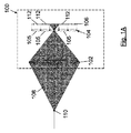
カメラまでの異なる深さ又は距離にある対象は、プレノプティックカメラのセンサに異なる照明パターンを生成する。図1Aは、主レンズ102と、マイクロレンズアレイ104(行および列に集められた複数のマイクロレンズ105によって形成される)と、強度、色および方向情報を感知するためにマイクロレンズアレイ104の背後に配置されたイメージセンサ106とを備えるプレノプティックカメラ100の模式図二次元図を示す。図1Aに示す実施例では、プレノプティックカメラ100は、マイクロレンズ配列104の共役面に配置された対象点110からの入射光線108を捕捉している。図1Bは、プレノプティックカメラ100のイメージセンサ106によって捕捉された光を表す。グリッドの各セルは、イメージセンサ106上の各マイクロレンズ105によって生成されたマイクロ画像112を表す。
Objects at different depths or distances to the camera produce different illumination patterns on the sensors of the prenoptic camera. FIG. 1A shows a
対象点110の画像がマイクロレンズアレイ104上に合焦されるとき、対象点110は、プレノプティックカメラ100の主レンズ102を介してMLAの共役面に配置され、マイクロレンズ105上の無限小点のみが照明される(実際には、無限小点ではなく、回折パターン)。さらに、マイクロレンズ105とイメージセンサ106との間の間隔は、マイクロレンズ105のほぼ焦点距離であるので、対応するマイクロ画像112のすべての画素は、図1Bに示すように、正確に同じ光強度を集める。ここに示される画像センサ平面上の全ての画像において、黒色は、光の欠如を表すために使用され、画素が白色であるほど強く照射されており、部分的な照明はグレーレベルで示されている。
When the image of the
一方、対象ワールドのマイクロレンズアレイ104の共役面よりも近いシーンの対象ポイント110は、画像ワールドの焦点がマイクロレンズアレイ104よりも遠く(より右側に向かって)あり、センサ画素によって捕捉されるパターンが異なるので、より多くのマイクロレンズ105を照明する。このシナリオの図は、図2Aに示されており、図2Bは、イメージセンサ106上に生成された対応するパターンを示している。
On the other hand, the
逆に、マイクロレンズアレイ104の共役面よりも遠い対象点110も、より多くのマイクロレンズ105を照明するが、ここでは、焦点は、マイクロレンズアレイ104の位置よりも主レンズ102に近く、したがって、イメージセンサ106によって捕捉されるパターンは、図3Aおよび図3Bに示されるように、2つの上述の状況とは異なる。マイクロ画像112のいくつかにおけるグレーレベルは、部分的に照明された画素に対応し、一方、白画素においては、画素の全領域が、対象ワールドにおける対象ポイント110から来る光によって照射されている。
Conversely, a
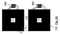
イメージセンサ106によって捕捉されたライトフィールドのこれらの様々なパターンは、ライトフィールドの2次元スライスを撮影することによってエピポーラ画像で表すことができる。図4A〜図4Cは、それぞれ、図3A〜図3Cのシナリオのそれぞれ1つについて、イメージセンサ106によって取り込まれた画素を再編成することによる、水平エピポーラ画像400(上段)および垂直エピポーラ画像402(下段)の生成プロセスを示す。図4Aの例では、対象ポイント110は、マイクロレンズアレイ104の共役面に配置され、図4Bでは、対象ポイント110は、マイクロレンズアレイ104の共役面よりも近くに、図4Cでは、マイクロレンズアレイ104の共役面よりも遠くに位置する。
These various patterns of the light field captured by the
水平エピポーラ画像400は、ライトフィールドの座標(py、ly)を固定することによって形成され、垂直エピポーラ画像402は、座標(px、lx)を固定することによって形成される。図4A〜4Cでは、水平エピポーラ画像400および垂直エピポーラ画像402は、それぞれ、水平中心エピポーラ画像および垂直中心エピポーラ画像であり、これは、エピポーラ画像のために固定された画素py及びpxが、それぞれのマイクロレンズの水平中心および垂直中心の画素だからである。図4A〜図4Cは、垂直エピポーラ画像402(下列)および水平エピポーラ画像400(上列)が、取り込まれたライトフィールドから直接形成される様子を示す。
The
図4Dは、同じ行ly((図4Dの実施例のly=3では、マイクロレンズアレイ104の水平中心マイクロレンズ105)に位置するマイクロレンズ105に対応するマイクロ画像112の高さpy=Yに位置する画素ライン(410、412、414、416、418)を積み重ねることによって形成される水平エピポーラ画像400(図4Aの上の行のズームビュー)の生成プロセスをより詳細に示す。マイクロ画像112内の画素ライン(410、412、414、416、418)の選択された高さpy=Yが中心高さであるので、水平エピポーラ画像400は、水平中心エピポーラ画像と考えられる。図4Dの各画素ライン(410、412、414、416、418)を形成する個々の画素(px=1、px=2、…)は図示されていない。対照的に、各垂直エピポーラ画像(402)は、同じ列lxに位置するマイクロレンズ105に対応するマイクロ画像112の所定の幅px=Xに位置する画素ラインを積み重ねることによって形成される。
FIG. 4D shows the height py = Y of the
図4A〜図4Dから分かるように、水平エピポーラ画像400および垂直エピポーラ画像402には、エピポーラ線430(白色)が形成されている。図1B〜3Bの例に示すように、このエピポーラ線430のすべての照明された画素(白画素)は、対象ワールドの同じ対象点110に対応する。エピポーラ線430は、エッジとして検出されるエピポーラ画像内の接続された照明画素(黒画素ではない)のセットである。さらに、エピポーラ線430の傾きは、マイクロレンズ104上およびイメージセンサ106上に照射されるパターンのタイプに直接関連し、また、対象ワールドにおける対象ポイント対応する深さにも直接関連する。図4Dの例では、エピポーラ線430の傾きは∞であり(横軸に対して角度=90°)、これは、対象ポイント110がマイクロレンズ配列104(図1A)の共役面に配置されるような距離に対応する。勾配が正(角度が90°よりも小さい)である場合、対象ポイント110は主レンズ102に近く(図2A)、勾配が負(角度が90°よりも大きい)である場合、対象ポイント110は主レンズ102から遠い(図3A)。
As can be seen from FIGS. 4A to 4D, epipolar lines 430 (white) are formed in the
したがって、このパターンを知ることによって、画素によってサンプリングされたパターンを、サンプリングカメラ100を通してバックトレースし、そのようなパターンを生成する対象ポイント110の正確な深さ(dz)を得ることが可能である。深さと勾配との間の関係は、ライトフィールドを捕捉するために使用されるプレノプティックカメラ100の物理的寸法及び設計(既知である)に依存する。
Therefore, by knowing this pattern, it is possible to backtrace the pattern sampled by the pixels through the
したがって、エピポーラ線430のある勾配は、現実の3次元ワールドシーンの対象ポイント110のある深さに明確に関連する。
Therefore, a certain gradient of the
エピポーラ線の推定勾配は、ある対象の深さ情報を含む。勾配および深さは、同じ硬貨の2つの側面である(確定的な方法で勾配から深さを得ることが可能であり、その逆も可能であり、センサ画素が無限小ではないという事実による変換における定量化誤差のみを伴う)。勾配自体は、シーンの異なる対象の相対的な深さに関する情報を得るのに十分である。この相対情報(すなわち、勾配)は、同じ深度(同じ勾配)に位置するシーンの異なる対象を識別するなど、絶対的な深度情報を提供する必要がないいくつかの用途に有用であり得る。したがって、このようなシナリオでは、勾配の計算は十分であり、勾配から深さへの変換を省略することができる。 The estimated gradient of the epipolar line contains depth information for an object. Gradient and depth are two sides of the same coin (it is possible to get the depth from the gradient in a deterministic way and vice versa, the transformation due to the fact that the sensor pixels are not infinitesimal. With only quantification error in). The gradient itself is sufficient to get information about the relative depth of different objects in the scene. This relative information (ie, gradient) can be useful in some applications where it is not necessary to provide absolute depth information, such as identifying different objects in a scene located at the same depth (same gradient). Therefore, in such a scenario, the calculation of the gradient is sufficient and the gradient-to-depth conversion can be omitted.
本発明の方法は、マイクロレンズ配列104上のワールドの照射におけるエッジが存在する領域(または、対象ワールド上の同じエッジであるもの)ついてのみの、深さの計算に基づく。好ましい実施形態では、ある勾配を得るために、エピポーラ線430を形成する照明された画素に線形回帰が適用される。水平400または垂直402エピポーラ画像内のエピポーラ線430を分析するとき、水平(px)または垂直(py)次元に沿って分布された全てのプレノプティックビューは、同じ対象ポイント110がこれらの全てのビューによって捕捉されているので、考慮される。したがって、線形回帰法は、1次元に沿った冗長な情報を利用することによって、統計的ノイズを低減する。
The method of the present invention is based on the calculation of the depth only for the region where the edge exists (or the same edge on the target world) in the irradiation of the world on the
さらに、この方法は、水平方向400および垂直方向402のエピポーラ画像内の同じ対象ポイント110を分析し、同じ対象ポイント110の情報を含む様々なエピポーラ画像(400、402)で得られた深度値を考慮することによって、統計的ノイズをさらに低減する追加ステージを含む(例えば、図1〜図4に示すように、対象ワールド内の一意の対象ポイント110が、イメージセンサ106のいくつかの点にいくつかのインプリントを生成し、これらのインプリントがいくつかの垂直方向およびいくつかの水平方向エピポーラ画像に現れる)。
In addition, this method analyzes the
一実施形態では、水平エピポーラ画像400および垂直エピポーラ画像402に形成されたすべてのエピポーラ線430が識別され、対応する勾配が計算される。次いで、対象ポイント110の対応する深さが、装置の物理的寸法を考慮することによって計算される。
In one embodiment, all
エピポーラ線は、いくつかの視点から捕捉された同じ対象点110によって形成されるので、エピポーラ線430当たり1つの勾配および深度値だけが計算される。このため、以下の2つの要因により、データ量が大幅に削減される。
Since the epipolar line is formed by the same point of
(i)イメージセンサ106によって捕捉された全ての点を処理する他のアプローチと比較して、本方法は、関心のある点、すなわち、エッジとして検出される対象ワールドの領域のみを処理するが、これは、それらがエピポーラ線を生成するからである(エッジのない完全に均一な対象ワールドの領域として、エピポーラ線を生成せず、均一な色を生成するからである)。
(I) Compared to other approaches that process all points captured by the
(ii)エピポーラ線430を形成する画素毎に1つの値を記憶する代わりに、エピポーラ線430毎に1つの勾配値のみを記憶することが可能である。
(Ii) Instead of storing one value for each pixel forming the
したがって、この計算プロセスの出力は、これらの検出された勾配の対応する深度値だけであってもよい。 Therefore, the output of this calculation process may be only the corresponding depth values of these detected gradients.
垂直エピポーラ画像402および水平エピポーラ画像400の両方を分析するときに同じセンサ画素が考慮され、したがって、いくつかの勾配値が対象ワールドの同じ点によって生成された可能性がある。このため、一実施形態によれば、水平エピポーラ画像400および垂直エピポーラ画像402を分析することによって得られる勾配とエピポーラ線430を一つの4次元マトリックスに結合して、出力の信頼性が追加測定の冗長性によって改善されるという事実のために、統計的なノイズを減らす。
The same sensor pixels were considered when analyzing both the vertical
計算された勾配は、プレノプティックカメラ100の物理的パラメータを考慮することによって、対応する対象の深さに変換される。一実施形態では、この変換段階は、すべての冗長な勾配を組み合わせた後に実行され、勾配から深度への変換の数を大幅に低減する。
The calculated gradient is converted to the corresponding depth of object by taking into account the physical parameters of the
別の実施形態では、予め生成された深さ/勾配の4多次元マトリックスは、2次元の疎な深さ/勾配マップ(対象ワールドにエッジが存在する場合にのみ読み取り値を提供するため、疎な)に結合され、統計的ノイズをさらに低減し、したがって、深度マップの品質を向上させる。
In another embodiment, the pre-generated depth /
さらに別の実施形態では、水平エピポーラ画像400および垂直エピポーラ画像402内のエピポーラ線430について計算された深さ/勾配は、2次元の疎深さ/勾配マップ直接結合され、したがって、単一の結合段階を実行し、計算効率を向上させる。
In yet another embodiment, the depths / gradients calculated for the
一実施形態では、疎深度/勾配マップは、画像充填技法を適用して、すべての画素(dx、dy)について深度/勾配値を取得することによって充填される。 In one embodiment, the sparse depth / gradient map is filled by applying an image filling technique to obtain depth / gradient values for all pixels (dx, dy).
さらに別の実施形態では、図4A〜4Dに示すように、水平中心エピポーラ画像(座標をマイクロ画像112内のpy寸法の中心画素に等しくなるように設定することによって形成される)のみ、および/または垂直中心エピポーラ画像(座標pxをマイクロ画像内のpx次元の中心画素に等しくなるように、座標pxを取ることによって形成される)のみが、分析するエピポーラ画像の数を減らすことを目的として考慮され、したがって、統計的冗長性を減らす代わりに、性能が向上する。 In yet another embodiment, as shown in FIGS. 4A-4D, only the horizontal center epipolar image (formed by setting the coordinates to be equal to the center pixel of the py dimension in the microimage 112) and / Or only the vertical center epipolar image (formed by taking the coordinate px so that the coordinate px is equal to the central pixel of the px dimension in the microimage) is considered for the purpose of reducing the number of epipolar images to analyze. Therefore, performance is improved at the cost of reducing statistical redundancy.
本発明の方法は、プレノプティックカメラを備えたモバイル装置(例えば、スマートフォン、タブレット、またはラップトップ)において実施することができる。 The method of the present invention can be carried out on a mobile device (eg, a smartphone, tablet, or laptop) equipped with a prenoptic camera.
図5は、一実施形態による、深度マップを生成するための方法のフロー図を示す。深度マップを生成するために、本方法は、プレノプティックカメラ100によって捕捉されたライトフィールド(501)から水平(502)及び垂直エピポーラ画像(503)を生成する。生成された各水平エピポーラ画像(502)および垂直エピポーラ画像(503)について、エピポーラ画像内の有効なエピポーラ線(510、511)が識別される。次に、これらの有効なエピポーラ線(510、511)の勾配(512、513)が計算され、対応する深度値(514、515)が最終的に得られる。
FIG. 5 shows a flow chart of a method for generating a depth map according to one embodiment. To generate a depth map, the method produces horizontal (502) and vertical epipolar images (503) from the light field (501) captured by the
図5は、有効なエピポーラ線(510、511)を識別し、処理し、捕捉されたライトフィールドを入力として取り込み(501)、すべての水平エピポーラ画像(502)および垂直エピポーラ画像(503)(図5の「EPI」)を処理し、以下のステップを実行するプロセスを説明する。
FIG. 5 identifies and processes valid epipolar lines (510, 511), captures captured light fields as inputs (501), and captures all horizontal epipolar images (502) and vertical epipolar images (503) (FIG. 5). A process of
ステップ502では、各水平エピポーラ画像について、固定された2つの値(py、ly)が得られる。
In
ステップ504では、lx次元に沿って1次元(またはそれ以上)のフィルタを適用して、ノイズを低減し、フィルタリングされた水平エピポーラ画像を得る。
In
ステップ506では、各画素(px、lx)について、lx次元に沿った画素の光強度またはコントラストにわたる画素(px、lx)における空間二次導関数を計算する。
In
ステップ508では、サブ画素精度でエピポーラ線を分析することによって、より具体的には、空間二次導関数のゼロ交差を検出することによって、対象ワールドのエッジを決定する。
In
ステップ10では、有効なエピポーラ線を形成するように正しく配置されたゼロ交差の1つごとに探索し、無効なエピポーラ線を廃棄する。
In
ステップ503では、各垂直エピポーラ画像について、固定された2つの値(px、lx)が得られる。
In
ステップ505では、ノイズを低減するために、ly次元に沿って1次元フィルタを適用し、フィルタリングされた垂直エピポーラ画像を得る。
In
ステップ507では、各画素(py、ly)について、ly次元に沿って空間二次導関数を計算する。
In
ステップ509では、サブ画素精度でエピポーラ線を分析することによって、より具体的には、空間二次導関数のゼロ交差を検出することによって、対象ワールドのエッジを決定する。
In
ステップ511では、有効なエピポーラ線511を形成するように正しく配置されたゼロ交差の1つごとに探索し、無効なエピポーラ線を廃棄する。
In
ステップ512、513では、水平エピポーラ画像および垂直エピポーラ画像の両方で見出される各有効エピポーラ線(ステップ510、511)について、サブ画素精度エッジは、線形回帰法を実行することによって、有効エピポーラ線(ステップ510、511)の勾配を決定するために使用される(しかし、任意の他のフィッティング技術も使用される)。
In
ステップ514、515では、計算された各勾配に対して、変換勾配から深度値への変換が適用される。
In
最後に、ステップ516、517では、2つの深度マトリックス、すなわち、水平エピポーラ画像(ステップ502)に対する水平深度マトリックスと、垂直エピポーラ画像(ステップ503)に対する垂直深度マトリックスとが生成される。
Finally, in
フィルタリングされた水平(ステップ504)または垂直エピポーラ画像(ステップ505)を得るためのノイズ低減フィルタステップは、処理速度を上げるために任意選択で省略されてもよい。 The noise reduction filter step for obtaining a filtered horizontal (step 504) or vertical epipolar image (step 505) may be optionally omitted to increase processing speed.
別の実施形態では、水平エピポーラ画像(ステップ502)および垂直エピポーラ画像から得られる(ステップ503)2つの勾配マトリックスは、単一の勾配マトリックスに結合され、最終的に単一の深度マトリックスを得る。 In another embodiment, the two gradient matrices obtained from the horizontal epipolar image (step 502) and the vertical epipolar image (step 503) are combined into a single gradient matrix to finally obtain a single depth matrix.
一実施形態によれば、空間二次導関数のゼロ交差は、空間二次導関数の連続する正負または負正の値によって識別される。更に、サブ画素精度を得るために、これらの点の二次導関数の大きさは、実際のゼロ交差がどこで起こっているかを決定するために考慮される。当業者は、多くの他のエッジ検出方法(例えば、Cannyエッジ検出器オペレータ、曲線フィッティング方法、またはモーメントベースの方法)もこの目的のために適用することができ、本明細書で説明する技法はゼロ交差方法に限定されないことを認識するであろう。しかし、検出されたエッジによって形成される線の勾配を決定するときに可能な限り最大の精度を得ることが非常に重要であり、それが、エッジを決定するためのサブ画素精度が非常に重要である理由である。提案された方法の目標の1つは、計算的に効率的であることである(この要件は、採用されるエッジ検出アルゴリズムを選択するときに考慮されるべきである)。 According to one embodiment, the zero crossing of the spatial second derivative is identified by a negative or negative-positive values consecutive spatial second derivative. Furthermore, in order to obtain sub-pixel accuracy, the magnitude of the quadratic derivatives of these points is taken into account to determine where the actual zero intersection is occurring. One of ordinary skill in the art can also apply many other edge detection methods (eg, Canny edge detector operator, curve fitting method, or moment-based method) for this purpose, and the techniques described herein are: You will recognize that it is not limited to the zero crossing method. However, it is very important to get the maximum possible accuracy when determining the slope of the line formed by the detected edges, which is why the sub-pixel accuracy for determining the edges is very important. That is the reason. One of the goals of the proposed method is to be computationally efficient (this requirement should be taken into account when choosing the edge detection algorithm to be adopted).
全ての画素がカメラまでの光源の距離とは無関係に、全く同じ光強度を記録するので、完全に均一な(テクスチャまたは色のコントラストなし)対象ワールドの領域は、エピポーラ線を生成しない。図1〜図4に示す全ての実施形態は、エピポーラ画像(400、402)内にエピポーラ線430を生成する1つの放射点光源(対象点110)によって、「暗い」対象ワールドに対応する。
A perfectly uniform region of the target world (no texture or color contrast) does not produce epipolar lines, as all pixels record exactly the same light intensity regardless of the distance of the light source to the camera. All embodiments shown in FIGS. 1-4 correspond to a "dark" target world with a single radiant point light source (target point 110) that produces
実際の状況では、エピポーラ線430は、コントラストの変化または色の変化によって生成され、それが、エピポーラ線430が対象ワールドのエッジ(色またはコントラストの変化)に対応する理由である。
In a real situation, the
したがって、エピポーラ線430は、対象のエッジによって生成される。エピポーラ画像の一次導関数(すなわち、画素の強度にわたる)は、勾配(すなわち、光強度またはコントラストが変化する速さ)を提供する。二次導関数は、コントラストがどこで最も速く変化しているかを示す(これは、対象ワールドにおける対象のエッジ対応する)。二次導関数は、所与の画素において必ずしもゼロ交差を有するとは限らないので(例えば、図6Aのエピポーラ画像は、あるグレーレベルを有するなど、画素における光の強度の値に依存するので)、対象のエッジは、サブ画素数精度で決定されている。
Therefore, the
プレノプティックカメラ100のまさにその性質および設計上の制約のために、エピポーラ画像内で有効なエピポーラ線(ステップ510、511)を形成する画素は、必然的に隣接する位置になければならず(すなわち、有効なエピポーラ線を形成する点が接続されなければならない)、エピポーラ線内で上下、または下上のように、同じ方向に向かうすべての点を有する線を構成しなければならない。
Due to the very nature and design constraints of the
図6A〜図6Cは、エピポーラ画像600における有効なエピポーラ線610の例(図6A)と、それぞれのエピポーラ画像(602、604)における無効なエピポーラ線(612、614)のいくつかの例(図6Bおよび図6C)とを示す。好ましい実施形態では、有効なエピポーラ線を形成するためにエピポーラ画像内のエッジを探すときに、隣接する位置のみが考慮される(エッジとして検出された中心画素から始まり、図6A〜図6Cの矢印は、エピポーラ線を形成する接続されたエッジ画素を決定するために考慮される隣接する位置を表す)。その結果、図6Aに示されるもののようなエピポーラ線610は有効であると考えられ、一方、図6Bに示されるもののようなエピポーラ線612は、エピポーラ画像602の頂部620の画素および底部622の画素がエピポーラ線612の残りの部分に接続されていないので、無効であると検出される。
6A-6C show examples of
一見すると、図6Cに示すようなエピポーラ線614は、有効なエピポーラ線と思われるかもしれない。しかし、プレノプティックカメラ100の性質のために、そのような線は、欠陥のない装置では起こらない(上部630および下部632の画素は、エピポーラ線の残りの部分と同じ方向に従わない)。一実施形態では、こういった種類の線の、こうした端の画素(630、632)は、エピポーラ線の勾配を計算するときに省略することができ、外側の画素が主レンズの収差から生じる可能性があるので、依然として有効なエピポーラ線と見なすことができる。このようにして、我々は、受光パワーと勾配識別性能とを交換して、アパーチャの最も収差のある周辺部分を横切る光線によって形成される端の画素の収差を低減する。また、有効でないエピポーラ線を用いて計算を実行することを回避するために、線全体を無効としてラベル付けすることも可能である。
At first glance, the
発見的には、人間が、線の形態を視覚的に検査することによって、有効なエピポーラ線と有効でないエピポーラ線とを区別することは容易である。しかし、コンピュータ上で決定を下すアルゴリズムは簡単ではない。当業者にとって、そのタスクを実行するためのいくつかの異なるアルゴリズムを考えることは困難ではなく、形態を分析する任意のアルゴリズムの特定の実装は、本発明の内容には無関係である。有効なエピポーラ線をどのように識別するか、およびそのタスクを実行するための多くのコンピュータ・ソリューションをどのように開発することができるかは、発見的に定義されている。 Discoverably, it is easy for humans to distinguish between valid and ineffective epipolar lines by visually inspecting the morphology of the lines. However, the algorithms for making decisions on a computer are not easy. It is not difficult for those skilled in the art to think of several different algorithms for performing the task, and the particular implementation of any algorithm that analyzes the morphology is irrelevant to the content of the present invention. How to identify valid epipolar lines and how many computer solutions to perform that task can be developed is discoveryally defined.
一実施形態では、エピポーラ画像の高さと少なくとも同数の照明画素数を有するエピポーラ線のみが有効な線とみなされる。これは、収差が実際に(光学的に又は前の段階で計算的に)補正された装置における勾配計算の精度を高めることができる。 In one embodiment, only epipolar lines having at least as many illumination pixels as the height of the epipolar image are considered valid lines. This can increase the accuracy of the gradient calculation in the device where the aberrations are actually (optically or computationally) corrected in the previous step.
主レンズ102の最も高い収差は、レンズの両端(近軸近似がもはや有効でない中心から遠い領域)で生じる。主レンズ102のこれらの端の部分を通過する全ての光線は、その中心に近いレンズを横切る光線よりも収差が大きい。プレノプティックカメラ100では、これらの光線は、すべてのマイクロ画像112の端の画素、またはすべてのマイクロレンズ104の端の画素によって捕捉され、これらはまた、エピポーラ画像上部または下部の近くの端の画素640(図6A)である。したがって、一実施形態では、エピポーラ画像の端の画素数640を省略して、光学収差の影響を低減するとともに、検出される深度値の数を増加させることができる(端の画素を廃棄することによって、有効なエピポーラ線の数を増加させる)。したがって、エピポーラ画像の画素の高さよりも少ない画素を有するエピポーラ線も、例えば、図6Bおよび図6Cにおいて、それらの上部(620、630)および下部(622、632)の画素を廃棄するように、有効であると考えることができる。
The highest aberrations of the
図6D〜6Gは、図6Aのエピポーラ画像600におけるエピポーラ線610の勾配の計算プロセスの一例を表す。この例では、図6Dの表642に示されるように、以下の画素の強度値「I」が考慮されている:黒い画素について0の値、暗いグレー画素について20の値、明るいグレー画素について60の値、および白い画素について100の値(を割り当てる)。図6Eの表644は、以下の式に従って、lx次元に沿った強度Iの画素数iにおける数値的な二次導関数を表す。
6D-6G represent an example of the process of calculating the gradient of the

ここで、i+1は、後続の画素を表し、i−1は、lx次元にわたって先行する画素を表す。連続する画素間の距離Δlxは常に同じである(Δlx=1の値とみなされる)。 Here, i + 1 represents a subsequent pixel, and i-1 represents a preceding pixel over the lp dimension. The distance Δlx between consecutive pixels is always the same (considered as a value of Δlx = 1).
図6Fは、1x次元(水平サブ軸)に沿ったすべての画素px(横軸)についての2次導関数(縦軸)の値を有するグラフ646を示し、連続する正負または負正の値によって識別される2次導関数のゼロ交差650を示す。先に説明したように、対象ワールド内の対象のエッジは、空間二次導関数のゼロ交差650を検出することによって決定される。
FIG. 6F shows a
図6Gは、図6Aのエピポーラ画像600において、サブ画素精度を有するゼロ交差650を示す。サブ画素精度を理解するために、マイクロレンズlx=2(二次導関数値100を有する)とlx=3(二次導関数値ど−200を有する)との間の画素px=1について生じたゼロ交差は、ズームインする。両方の2次導関数値を接続する線652は、サブ画素精度でlx=2の内側に位置するゼロ交差650のゼロ縦座標と交差する。図6Gのエピポーラ線610の勾配は、検出されたゼロ交差650に線形回帰656を適用し、線形回帰656の勾配を直接計算することによって得られる。
FIG. 6G shows zero
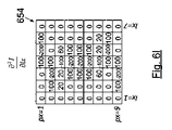
図6H〜図6Jは、図6Bのエピポーラ画像602におけるエピポーラ線612の勾配の計算プロセスの別の例を表す。画素の強度値Iは、図6Hの表653に示され、一方、図6Iの表654は、二次導関数値を表す。ゼロ交差650は計算され、図6Jに点として示される。エピポーラ線612の勾配は、検出されたゼロ交差650に線形回帰658を適用することによって計算される。図6Jのエピポーラ線612の線形回帰658は、画素数620および622からそれぞれ得られるゼロ交差650aおよび650bのために、図6Gのエピポーラ線610の線形回帰656よりも高い勾配を有することに留意されたい。
6H-6J represent another example of the process of calculating the gradient of the
一実施形態では、すべてのゼロ交差は、線形回帰において考慮される。しかし、別の実施形態では、ゼロ交差のいくつかは、予め廃棄してもよく、エピポーラ線の勾配を得るプロセスでは考慮されなくてもよい。線形回帰法を適用するために使用される残りの点と比較して高い分散を有する点は、より正確な勾配推定を得るために、または異常値を廃棄するために、このプロセスから識別され、除外することができる。例えば、図6Jでは、上部620および底面622画素は、上部620および下部622の画素はエピポーラ線612を生成する残りの画素に接続されていないため(この場合、上部620および下部622の画素は、主レンズ102の異常によって引き起こされた可能性がある)、線形回帰658(図6Gのエピポーラ線610について得られた勾配に類似した勾配を有するエピポーラ線を得る)を計算する際に、エピポーラ画像602の上部画素620によって生じるゼロ交差650aおよびエピポーライメージ602の底面画素622によって生じるゼロ交差650bを廃棄してもよい。
In one embodiment, all zero intersections are considered in linear regression. However, in another embodiment, some of the zero intersections may be pre-discarded and may not be considered in the process of obtaining the slope of the epipolar line. Points with high variance compared to the remaining points used to apply the linear regression method are identified from this process to obtain more accurate gradient estimates or to discard outliers. Can be excluded. For example, in FIG. 6J, the top 620 and bottom 622 pixels are such that the top 620 and bottom 622 pixels are not connected to the remaining pixels that generate the epipolar line 612 (in this case, the top 620 and bottom 622 pixels are
二次導関数644が計算されると、それらが有効なエピポーラ線を定義するか否かが決定される。このプロセスでは、先に説明したように、いくつかの画素に対応する二次導関数のいくつかの値を廃棄してもよい。線形回帰を有効なゼロ交差に適用して、それらの対応する勾配を計算する。逆に、有効でないと識別されたエピポーラ線のすべてについて、さらなる計算を実行する必要はない。
Once the
発見的方法、形態素解析、人工知能、または他の任意の方法を使用して、エピポーラ線が有効であるかまたは有効でないかをエピポーラ画像から事前に決定し、さらなる計算を回避することが可能であり、有効でないことを事前に分かっているエピポーラ線の勾配を計算しないことも可能である。 Heuristics, morphological analysis, artificial intelligence, or any other method can be used to predetermine from epipolar images whether epipolar lines are valid or not, avoiding further calculations. Yes, it is possible not to calculate the slope of the epipolar line, which is known in advance to be ineffective.
一実施形態では、検出された有効エピポーラ線に線形回帰を適用する場合、誤差見積りも計算することができる。一例として、エピポーラ線の点(すなわち、ゼロ交差)と最終的な推定回帰線との間の距離の和を誤差(すなわち、計算されたエピポーラ線とこのエピポーラ線を計算するために使用された点との間の距離の絶対値の加算)として使用することができる。しかし、任意の他のタイプのエラー計算を定義してもよい。 In one embodiment, if linear regression is applied to the detected valid epipolar lines, an error estimate can also be calculated. As an example, the sum of the distances between the points on the epipolar line (ie, the zero intersection) and the final estimated regression line is an error (ie, the calculated epipolar line and the point used to calculate this epipolar line). It can be used as an addition of the absolute value of the distance between and. However, any other type of error calculation may be defined.
一実施形態では、最大誤差閾値を使用して、エピポーラ線を廃棄する(そして、アルゴリズムの残りの部分では考慮しない)ことができる。そのために、計算された誤差が最大誤差閾値よりも高い場合、エピポーラ線は有効でないとみなし、計算された誤差が最大誤差閾値よりも低い場合、エピポーラ線は有効であるとみなす。 In one embodiment, the maximum error threshold can be used to discard epipolar lines (and not take into account in the rest of the algorithm). Therefore, if the calculated error is higher than the maximum error threshold, the epipolar line is considered invalid, and if the calculated error is lower than the maximum error threshold, the epipolar line is considered valid.
水平エピポーラ画像400は、例えば、図5の水平エピポーラ画像502の検出された有効エピポーラ線510に示されるように、いくつかのエピポーラ線(Nlxまでのエピポーラ線)を含んでもよい。同様に、垂直エピポーラ画像は、いくつかのエピポーラ線511を含んでもよい。図7Aは、2つの異なるエピポーラ線(図7Eの710および712)を含む水平エピポーラ画像700の例を示す。図7Aは、両方のエピポーラ線に対応するゼロ交差650の線形回帰(756、758)を示す。この例は、光パターンが、ここでは、無限小ではなく特定のサイズを有する対象によって生成されるので、図4および図6に提示されるものよりも現実的なシナリオを表す。それが、イメージセンサ106によって記録された高強度(白画素)が、図7Aのいくつかのマイクロレンズ(1x)を占有する理由である。
The
エピポーラ画像700の画素の強度値「I」は、図7Bの表720に示され、一方、図7Cの表730は、二次導関数値を表す。
The pixel intensity “I” of the
一実施形態では、エピポーラ画像の画素がエッジ画素731としてラベル付けされているか、または検出されているかを考慮する方法は、負の2次導関数を持ち、右側または左側に正の2次導関数を持つ画素を有する画素(px,lx)(図7Cのハイライトされた画素)を見つけることを含む。あるいは、図7D(図7Cの同じテーブル、二次導関数値)に示すように、エピポーラ画像の画素は、正の二次導関数を有し、右側または左側に負の二次導関数を有する画素(図7Dのハイライトされた画素)(px,lx)をエッジ画素731としてラベル付けしてもよい。
In one embodiment, the method of considering whether a pixel in an epipolar image is labeled or detected as an
エッジ画素731が検出されると、一実施形態によれば、エピポーラ画像内の有効なエピポーラ線を識別する手順が、(図7Cの2次導関数値およびエッジ画素731に対応する)図7Eの例を参照して説明される。
When the
中心画素(px=5)に対応し、エッジ画素731(エッジ画素AおよびJ)としてラベル付けされる中央行px(または垂直エピポーラ画像の場合はpy)に位置する水平エピポーラ画像の各画素lx(lx=1〜lx=11)(または垂直エピポーラ画像ではly)について、以下が行われる。
ステップ1
上側の隣接位置(lx、px−1)、(lx+1、px−1)、(lx−1、px−1)においてエッジ画素731としてラベル付けされた画素の検索:エッジ画素B(エッジ画素Aから始まる第1反復)およびエッジ画素K(エッジ画素Jから始まる第1反復)が見出される。
ステップ2
エッジ画素731が見つかった場合、lxおよびpxを新しいエッジ画素731の座標(エッジ画素Aから始まる最初の反復におけるエッジ画素Bの座標:lx=4、px=4;エッジ画素Jから始まる最初の反復におけるエッジ画素Kの座標:lx=8、px=4)で更新し、ステップ1(次に見つかったエッジ画素:エッジ画素Aから反復する際のエッジ画素D、FおよびH;エッジ画素Jから反復する際のエッジ画素MおよびO。エッジ画素Qは、エッジ画素Oに対してlx+2に位置するので、エピポーラ線の一部とはみなされない)を繰り返す。そうでなければ、ステップ3に進む。
ステップ3
下側の隣接位置(lx,px+1)、(lx+1,px+1)、(lx−1,px+1)におけるエッジとしてラベル付けされる画素の検索:エッジ画素C(反復がエッジ画素Aから開始するとき)及びエッジ画素L(エッジ画素Jから反復するとき)。
ステップ4
エッジ画素731が見つかった場合、lxおよびpxを新しいエッジ画素731の座標(エッジ画素Aから始まる最初の反復におけるエッジ画素C:lx=4、px=6;エッジ画素Jから始まる最初の反復におけるエッジ画素L:lx=8、px=6)で更新し、ステップ3(見つかった次のエッジ画素:エッジ画素Aから反復する際のエッジ画素E、GおよびI;エッジ画素Jから反復する際のエッジ画素NおよびP。エッジ画素Rは、エッジ画素Pに対してlx−2に位置するので、エッジ画素Rはエピポーラ線の一部とはみなされない)を繰り返す。そうでなければ、次のステップに進む。
Each pixel lp (or py) of the horizontal epipolar image corresponding to the center pixel (px = 5) and located in the center row px (or py in the case of a vertical epipolar image) labeled as edge pixels 731 (edge pixels A and J). For lx = 1 to lx = 11) (or ly in a vertical epipolar image), the following is done:
Search for pixels labeled as
If
Finding pixels labeled as edges at lower adjacent positions (lpx, px + 1), (lpx + 1, px + 1), (lpx-1, px + 1): Edge pixel C (when iteration starts at edge pixel A) and Edge pixel L (when repeating from edge pixel J).
If
この反復プロセスの結果は、(中心エッジ画素Aに対応する)第1のエピポーラ線710及び(中心エッジ画素Jに対応する)第2のエピポーラ線712である。第1のエピポーラ線710は、9個のエッジ画素(H、F、D、B、A、C、E、G、I)によって形成される。第2のエピポーラ線712は、7つのエッジ画素(O、M、K、J、L、N、P)によって形成される。
The result of this iterative process is the first epipolar line 710 (corresponding to the central edge pixel A) and the second epipolar line 712 (corresponding to the central edge pixel J). The
説明した反復プロセスにおいて中央行px内の特定のlxについて検出されたエッジ画素731の数に応じて、エピポーラ線は有効または無効とみなすことができる。一実施形態では、検出されるエッジ画素731の数は、少なくともエピポーラ画像の画素の高さ(すなわち、図7Eの例では9)でなければならない。第1のエピポーラ線710は、9画素を有するので、この基準に従うが、第2のエピポーラ線712は、7画素のみで形成されるので、この基準に従わない。別の実施形態では、主レンズ102の光学収差の影響を低減するために、端の画素(px=1、px=9)を省略してもよい(この場合、検出されるエッジ画素731の数は、少なくともエピポーラ画像の画素の高さから2を引いたもの、すなわち図7Eでは7画素であるべきである)。この最後の実施形態では、図7Eのエピポーラ線(710、712)の両方が有効であると考えられる。
Epipolar lines can be considered valid or invalid, depending on the number of
エピポーラ線内のすべてのエッジ画素731の方向の一貫性に応じて、エピポーラ線は、(エピポーラ画像内の同じ方向を指す)有効または無効とみなすことができる。例えば、第1のエピポーラ線710では、中央エッジポイントAから始まって、すべての上側エッジ画素(B、D、F、H)が位置lx−1またはlxに位置し、下側エッジ画素(C、E、G、I)がlx+1またはlx位置にあり、第1のエピポーラ線710の一貫した方向を形成する。同じことが、中央エッジポイントJから始まる第2のエピポーラ線712にも当てはまり、すべての上側エッジ画素(K、M、O)は位置lx−1またはlxに位置し、下側エッジ画素(L、N、P)はlx+1またはlx位置にある。
Depending on the orientation consistency of all
一実施形態では、これらの2つの基準(エピポーラ線について検出されるエッジ画素731の数および方向の一貫性)の両方は、エピポーラ線が有効なものとみなされるために準拠しなければならない。
In one embodiment, both of these two criteria (consistency of the number and orientation of
したがって、図7Eに記載された実施形態によれば、エピポーラ線を有効であると考える。 Therefore, according to the embodiment described in FIG. 7E, the epipolar line is considered to be effective.
−第1に、対象のエッジに対応するエピポーラ画像内の画素(すなわちエッジ画素731)が、2次導関数値を使用して検出される。 -First, the pixels in the epipolar image corresponding to the edge of interest (ie, the edge pixels 731) are detected using the quadratic derivative value.
−次に、エピポーラ線を形成する1組の接続されたエッジ画素が得られる。エッジ画素AおよびJから始まる、図7Eで予め定義された反復プロセスのような、異なるアルゴリズムを使用することができる(矢印は、エピポーラ線を形成する接続されたエッジ画素のセットを得るために、隣接するエッジ画素を探す上向きおよび下向きの反復探索方向を示す)。 -Next, a set of connected edge pixels forming the epipolar line is obtained. Different algorithms can be used, such as the iterative process defined in FIG. 7E, starting with edge pixels A and J (arrows indicate to obtain a set of connected edge pixels forming epipolar lines. Indicates upward and downward iterative search directions for finding adjacent edge pixels).
−1つまたは複数の基準(例えば、セット内のエッジ画素の数およびセット内のエッジ画素のコヒーレント方向)に基づいて、エピポーラ線は有効または無効とみなされる。 -Epipolar lines are considered valid or invalid based on one or more criteria (eg, the number of edge pixels in the set and the coherent direction of the edge pixels in the set).
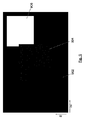
有効なエピポーラ線が検出されると、この線の勾配が計算される。この勾配値は、勾配と距離値との間に直接関係があるので、次に、深度値に直接変換されてもよい。分析されたエピポーラ線の勾配が計算されると、一実施形態によれば、この方法により、プレノプティックカメラによって捕捉されたシーンの対象のエッジの深度値(dz)を含む疎な2次元深度マップが出力される。深度マップの座標(dx、dy)は、対応する対象ポイントの横方向位置(すなわち、対象ワールドの2次元座標)を示し、深度値(dz)は、対象ワールド内の対応する座標(dx、dy)の深度を表す。図8は、異なる深度における3つの対象(802、804、806)を示す疎深度マップのエッジを示し、黒色は、深度値が割り当てられていないことを表し、深度値がより白くなるほど、シーン内の物体はより遠くなる。 When a valid epipolar line is detected, the slope of this line is calculated. Since this gradient value has a direct relationship between the gradient and the distance value, it may then be converted directly into a depth value. Once the slopes of the analyzed epipolar lines have been calculated, according to one embodiment, this method is a sparse two-dimensional containing the depth value (dz) of the edge of the scene captured by the prenoptic camera. The depth map is output. The coordinates (dx, dy) of the depth map indicate the lateral position of the corresponding target point (that is, the two-dimensional coordinates of the target world), and the depth value (dz) indicates the corresponding coordinates (dx, dy) in the target world. ) Represents the depth. FIG. 8 shows the edges of a sparse depth map showing three objects (802, 804, 806) at different depths, black represents no depth value assigned, the whiter the depth value, the more in the scene. The object is farther away.
この方法は、前の段階で得られたエピポーラ線の勾配を考慮して、疎深度マップを生成する追加ステージを含んでもよい。疎深度マップは、以前に算出されたエッジ(dx、dy)に、実ワールドの対象の深度値(dz)を割り当てることにより得られる。 This method may include an additional stage to generate a sparse depth map, taking into account the slopes of the epipolar lines obtained in the previous step. The sparse depth map is obtained by assigning the previously calculated edges (dx, dy) to the target depth values (dz) in the real world.
一実施形態では、疎深度マップ生成への入力は、2つのマトリックス(水平深度マトリックス516および計算された深度値(dz)およびライトフィールド構造(px、py、lx、ly)の対応する位置に関連する垂直深度マトリックス517)である。疎深度マップ生成への入力は、前のステップで得られた2つの勾配マトリックス(512、513)であり得る。この場合、疎勾配マップが最初に得られ、深度への変換がこの2次元勾配マップにのみ適用され、したがって、計算要件が低減される。
In one embodiment, the input to the sparse depth map generation is related to the corresponding positions of the two matrices (
水平深度マトリックス516は、水平エピポーラ画像を分析することによって得られ、一方、垂直深度マトリックス517は、垂直エピポーラ画像から得られる。最新技術におけるこれらのマトリックス(516、517)の各々のサイズは、Npx×Npy×Nlx×Nlyである。ここで、NpxおよびNpyは、水平及び垂直方向のマイクロ画像における画素数であり、NlxおよびNlyは、水平および垂直マイクロレンズの数である。
The
エピポーラ線の線形回帰を行う場合、1つの勾配値のみを得ることが可能である。したがって、一実施形態では、この段階の入力マトリックスのサイズは、線形回帰法によって生成されるすべてのエピポーラ線についての深度/勾配値のみを格納するように大幅に低減することができ、その結果、水平深度マトリックスのサイズはNpy×Nly×Nlx(水平エピポーラ画像は、最大Nlxのエピポーラ線を含んでもよい)となり、垂直深度マトリックスのサイズはNpx×Nlx×Nly(垂直エピポーラ画像は、最大Nlyのエピポーラ線を含んでもよい)となる。 When performing linear regression of epipolar lines, it is possible to obtain only one gradient value. Therefore, in one embodiment, the size of the input matrix at this stage can be significantly reduced to store only the depth / gradient values for all epipolar lines generated by the linear regression method, as a result. The size of the horizontal depth matrix is Npy x Nly x Nlx (horizontal epipolar image may contain epipolar lines of maximum Nlx), and the size of the vertical depth matrix is Npx x Nlx x Nly (vertical epipolar image is epipolar of maximum Nly). It may include a line).
一実施形態では、2つの深度/勾配マトリックスは、水平中心エピポーラ画像および垂直中心エピポーラ画像(または任意の他のエピポーラ画像)において分析される点のみを含んでもよく、マトリックスのサイズは、それらの両方についてNlx×Nlyである。 In one embodiment, the two depth / gradient matrices may contain only the points analyzed in the horizontal center epipolar image and the vertical center epipolar image (or any other epipolar image), and the size of the matrix may be both of them. Is Nlx × Nly.
エピポーラ画像内の対応する位置において有効なエピポーラ線が検出されていない(エッジが検出されていない)ので、これらのマトリックスの多くの点は、計算された深度値を有さなくてもよい。 Many points in these matrices do not have to have calculated depth values, as no valid epipolar lines have been detected (no edges have been detected) at the corresponding positions in the epipolar image.
得られたあらゆる深度値(dz)を対象ワールドの2次元座標(dx、dy)に割り当て、計算された点の勾配に応じて深度マップ(dx、dy、dz)を得、点の座標(px、py、lx、ly)(すなわちセンサ上の位置)を考慮するために、組み合わせ段階を使用することができる。図1〜図4から分かるように、対象ポイント110は、エピポーラ線上の異なる勾配と同様に、センサ上に異なるパターンを生成する。したがって、勾配を計算し、センサ上の位置(px、py、lx、ly)を知ることによって、検出されたエピポーラ線ごとに対応するワールド位置(dx、dy)を見つけることが可能である。
All the obtained depth values (dz) are assigned to the two-dimensional coordinates (dx, dy) of the target world, the depth map (dx, dy, dz) is obtained according to the calculated gradient of the point, and the coordinates of the point (px). , Py, lp, ly) (ie, position on the sensor) can be used in combination steps. As can be seen from FIGS. 1 to 4, the
対象ワールドの単一のエッジが、わずかに異なるノイズ、収差、閉塞、または量子化誤差によって影響を受けるいくつかのエピポーラ線を発生させ、異なる勾配、したがって異なる深さを有するエピポーラ線をもたらすことができるので、いくつかの異なる値dzが、同じペア(dx、dy)について取得され得る。また、水平エピポーラ線のいくつかと垂直エピポーラ線のいくつかは、わずかに異なる値dzを生じることがある。 A single edge of the target world can generate several epipolar lines that are affected by slightly different noise, aberrations, blockages, or quantization errors, resulting in epipolar lines with different gradients and thus different depths. So that several different values dz can be obtained for the same pair (dx, dy). Also, some of the horizontal epipolar lines and some of the vertical epipolar lines may produce slightly different values dz.
一実施形態では、2次元深度マップ(dx、dy座標毎に単一の値dz)を生成するときに、統計的ノイズを低減するために、すべての冗長深度値(dzの異なる値)が単一の深度マップに結合される。 In one embodiment, when generating a two-dimensional depth map (single value dz for each dx, dy coordinate), all redundant depth values (different values of dz) are simply set to reduce statistical noise. Combined into one depth map.
深度マップ(dx、dy、dz)上に全ての深度値dzを取得する場合、同じ位置(dx、dy)に対していくつかの深度値dzを取得することができる。したがって、最終値を得るために、いくつかの方法を適用することができる。例として、限定されるものではないが、算術平均又は中央値又は他の平均化技術(重み付けされたポンデレーションを有する又は有さない)が、同じ深度マップ位置(dx、dy)に対して得られた全ての深度値(全てdzの値)に適用される。 When all depth values dz are acquired on the depth map (dx, dy, dz), several depth values dz can be acquired for the same position (dx, dy). Therefore, several methods can be applied to obtain the final value. As an example, but not limited to, arithmetic mean or median or other averaging techniques (with or without weighted pondering) can be obtained for the same depth map position (dx, dy). It is applied to all the depth values (all dz values).
この冗長性により、統計的ノイズが低減され、深度マップの品質が改善される。さらに、少なくとも1つの実施形態では、エピポーラ線について計算された誤差見積りは、例えば、同じ位置(dx、dy)に投影されたすべての値の中で最も低い誤差を有する値を選択することによって(例えば、エピポーラ線と、そのエピポーラ線の始まりの画素との間のすべての距離の加算、または任意の他の測定値を誤差として考慮することによって)、深度マップの特定の位置(dx、dy)の最終的な深度値(dz)を選択するために考慮することができる。 This redundancy reduces statistical noise and improves the quality of depth maps. Further, in at least one embodiment, the error estimates calculated for the epipolar line are made, for example, by selecting the value with the lowest error of all the values projected at the same position (dx, dy) ( For example, by adding all the distances between the epipolar line and the first pixel of that epipolar line, or taking any other measurement as an error), a particular position in the depth map (dx, dy). Can be considered to select the final depth value (dz) of.
より多くの深度値が得られると、冗長性が増大し、深度測定値の誤差が最小限に抑えられるので、より正確な深度マップが生成され得る。それにもかかわらず、計算量および実施態様の複雑さを低減するために、アルゴリズムによって考慮される冗長性を低減し、深度マップの品質も低減することがあり得る。 The more depth values obtained, the greater the redundancy and the minimal error in the depth measurements, which can result in a more accurate depth map. Nevertheless, in order to reduce computational complexity and complexity of embodiments, it is possible to reduce the redundancy considered by the algorithm and also reduce the quality of the depth map.
一実施形態では、2次元疎深度マップは、推定深度値を含む水平(または垂直)エピポーラ構造のあるプレノプティックビューを取得することによって、すなわち、ある画素(通常、収差の影響を受けにくいビューであるため、中心画素)に設定されたすべての点(px、py)を取得することによって、直接生成される。この場合、計算の複雑さは低減されるが、代わりに、冗長性がより少なくなり、場合によってはより疎な深度マップ(全てのマイクロレンズについての深度値のみ)が生成される。 In one embodiment, the 2D sparse depth map captures a prenoptic view with a horizontal (or vertical) epipolar structure containing estimated depth values, i.e., a pixel (usually less susceptible to aberrations). Since it is a view, it is directly generated by acquiring all the points (px, py) set in the center pixel). In this case, the computational complexity is reduced, but at the cost of less redundancy and in some cases a sparser depth map (only depth values for all microlenses) is generated.
一実施形態では、深度マップの解像度は、ゼロ交差境界検出段階で得られるサブ画素精度を利用するために、マイクロレンズの総数よりも大きくすることができる。 In one embodiment, the resolution of the depth map can be greater than the total number of microlenses to take advantage of the sub-pixel accuracy obtained in the zero intersection boundary detection step.
勾配値は、識別されたエピポーラ画像エッジ(エピポーラ線)でのみ得られるので、前の段階で得られた疎深度マップは、多数の画素に対してだけでなく、実ワールドの均一性がエピポーラ画像上にエッジを生成しない多数のマイクロレンズに対しても、多くの空位置を含む。一実施形態では、すべてのこの空の位置に対する対応する深度値は、隣接する位置の深度値を考慮することによって得ることができる。密な深度マップを得るためのこの手順は、「深度マップ補間」と呼ぶことができ、画像充填法における多くの従来技術を利用する。 Gradient values are obtained only at the identified epipolar image edges (epipolar lines), so the sparse depth map obtained in the previous step is not only for a large number of pixels, but also for real-world uniformity epipolar images. It also contains many vacant positions for many microlenses that do not produce edges on top. In one embodiment, the corresponding depth values for all this empty position can be obtained by considering the depth values of adjacent positions. This procedure for obtaining a dense depth map can be referred to as "depth map interpolation" and utilizes many prior art in image filling methods.
密な深度マップを得るために、疎深度マップを補間するために、いくつかの技法を適用することができる。したがって、これらのアプローチのいくつかは、限定ではなく単なる例であり、領域成長、分割およびマージ、およびクラスタリング技法の少なくとも何れか、ならびに画像処理のための従来技術で知られているいくつかの他のアプローチである。さらに、正則化方法を使用して、深度マップを補完することができる。 Several techniques can be applied to interpolate the sparse depth map to obtain a dense depth map. Therefore, some of these approaches are merely examples, not limitations, at least one of the region growth, partitioning and merging, and clustering techniques, as well as some others known in the prior art for image processing. Approach. In addition, regularization methods can be used to complement the depth map.
図9は、異なる深度にある3つの対象(902、904、906)を示す密な深度マップの例を示す。この図9は、図8で生成された疎深度マップの濃い深度マップをグレーレベルで示し、黒色は深度値が割り当てられていないことを表し、他はシーン内のオブジェクトである。 FIG. 9 shows an example of a dense depth map showing three objects (902, 904, 906) at different depths. In FIG. 9, the dark depth map of the sparse depth map generated in FIG. 8 is shown in gray level, black indicates that no depth value is assigned, and the others are objects in the scene.
好ましい実施形態によれば、本発明の方法は、スマートフォン、タブレット、またはラップトップなどの電子モバイル装置において実行される。図10A、10B、および10Cは、プレノプティックカメラ100によって取り込まれた画像1002から深度マップを取得するために、本方法を実行するように構成された処理ユニットまたは処理手段1004を有する電子モバイル装置1000の異なる実施形態を示す。
According to a preferred embodiment, the method of the invention is performed in an electronic mobile device such as a smartphone, tablet, or laptop. 10A, 10B, and 10C are electronic mobile devices having a processing unit or processing means 1004 configured to perform this method in order to obtain a depth map from
モバイル装置においてリアルタイムで深度マップを取得するために、本方法を極めて効率的な方法で実施することが非常に推奨される。これを達成するために、現在のマルチコアプロセッサ1006(図10A)に含まれる複数のコアを、モバイル装置からのプロセッサにおいてさえも利用することが可能であり、いくつかのアルゴリズム実行スレッドを、それらの各々が異なる動作を実行することを担当するように作成する。 It is highly recommended that this method be performed in a highly efficient manner in order to obtain a depth map in real time on mobile devices. To achieve this, multiple cores contained in the current multi-core processor 1006 (FIG. 10A) can be utilized even in processors from mobile devices, with several algorithm execution threads in theirs. Create each to be responsible for performing different actions.
一実施形態では、第1のCPU1008a(図10B)が水平エピポーラ画像502について説明したステップ(図5参照)を実行する一方で、第2のCPU1008bが垂直エピポーラ画像503に対して同じ動作を実行することを担当するように、2つのCPU実行スレッドが作成される。
In one embodiment, the
計算効率を高めるために、より高度な計算技術を使用することができる。例えば、グラフィックス処理ユニット(図10CのGPU1010)は、モバイル装置に含まれるものであっても、GPUは、動作を同時に実行することができる数百または数千のコアを含むので、使用することができる。したがって、一実施形態では、各エピポーラ画像(垂直および水平)は、アルゴリズムの実行をさらに加速するために、GPU1010の異なるコアで同時に処理される。
More advanced computational techniques can be used to increase computational efficiency. For example, even if the graphics processing unit (GPU1010 in FIG. 10C) is included in a mobile device, the GPU contains hundreds or thousands of cores capable of performing operations simultaneously, so it should be used. Can be done. Therefore, in one embodiment, each epipolar image (vertical and horizontal) is processed simultaneously on different cores of the
Claims (15)
ライトフィールド取得装置によって捕捉されたライトフィールドから複数のエピポーラ画像を生成するステップと、
前記エピポーラ画像において、前記ライトフィールド取得装置によって捕捉されたシーン内の対象のエッジに対応するエッジ画素を検出するためのエッジ検出ステップと、
各エピポーラ画像において、1組のエッジ画素によって形成される有効なエピポーラ線を検出するステップであって、前記有効なエピポーラ線を形成する全ての前記エッジ画素は接続されており、前記有効なエピポーラ線は一貫した方向を形成する、ステップと、
前記有効なエピポーラ線の勾配を決定するステップと、を含む方法。 A way to get depth information from a light field
Steps to generate multiple epipolar images from the light field captured by the light field acquisition device, and
In the epipolar image, an edge detection step for detecting edge pixels corresponding to the target edge in the scene captured by the light field acquisition device, and
In each epipolar image, a step of detecting a valid epipolar line formed by a set of edge pixels, wherein all the edge pixels forming the valid epipolar line are connected and the valid epipolar line is formed. Form a consistent direction, with steps,
A method comprising: determining the gradient of the effective epipolar line.
Applications Claiming Priority (1)
| Application Number | Priority Date | Filing Date | Title |
|---|---|---|---|
| PCT/EP2016/074992 WO2018072817A1 (en) | 2016-10-18 | 2016-10-18 | A device and method for obtaining distance information from views |
Publications (2)
| Publication Number | Publication Date |
|---|---|
| JP2020503817A JP2020503817A (en) | 2020-01-30 |
| JP6855587B2 true JP6855587B2 (en) | 2021-04-07 |
Family
ID=57184433
Family Applications (2)
| Application Number | Title | Priority Date | Filing Date |
|---|---|---|---|
| JP2019541848A Active JP6855587B2 (en) | 2016-10-18 | 2016-10-18 | Devices and methods for acquiring distance information from a viewpoint |
| JP2019541849A Active JP7043085B2 (en) | 2016-10-18 | 2016-12-20 | Devices and methods for acquiring distance information from a viewpoint |
Family Applications After (1)
| Application Number | Title | Priority Date | Filing Date |
|---|---|---|---|
| JP2019541849A Active JP7043085B2 (en) | 2016-10-18 | 2016-12-20 | Devices and methods for acquiring distance information from a viewpoint |
Country Status (9)
| Country | Link |
|---|---|
| US (2) | US11423562B2 (en) |
| EP (2) | EP3516625B8 (en) |
| JP (2) | JP6855587B2 (en) |
| KR (2) | KR20190065432A (en) |
| CN (2) | CN109997170B (en) |
| CA (2) | CA3040002C (en) |
| ES (2) | ES2866975T3 (en) |
| IL (2) | IL266041B (en) |
| WO (2) | WO2018072817A1 (en) |
Families Citing this family (34)
| Publication number | Priority date | Publication date | Assignee | Title |
|---|---|---|---|---|
| US11425357B2 (en) | 2015-02-13 | 2022-08-23 | Carnegie Mellon University | Method for epipolar time of flight imaging |
| US11493634B2 (en) | 2015-02-13 | 2022-11-08 | Carnegie Mellon University | Programmable light curtains |
| US10679370B2 (en) * | 2015-02-13 | 2020-06-09 | Carnegie Mellon University | Energy optimized imaging system with 360 degree field-of-view |
| US11972586B2 (en) | 2015-02-13 | 2024-04-30 | Carnegie Mellon University | Agile depth sensing using triangulation light curtains |
| US11747135B2 (en) * | 2015-02-13 | 2023-09-05 | Carnegie Mellon University | Energy optimized imaging system with synchronized dynamic control of directable beam light source and reconfigurably masked photo-sensor |
| FR3051584B1 (en) * | 2016-05-20 | 2019-11-01 | Safran | METHOD FOR THREE DIMENSIONAL RECONSTRUCTION USING A PLENOPTIC CAMERA |
| EP3510562A1 (en) | 2016-09-07 | 2019-07-17 | Starship Technologies OÜ | Method and system for calibrating multiple cameras |
| US10430994B1 (en) * | 2016-11-07 | 2019-10-01 | Henry Harlyn Baker | Techniques for determining a three-dimensional textured representation of a surface of an object from a set of images with varying formats |
| US11652978B2 (en) * | 2017-01-05 | 2023-05-16 | Eys3D Microelectronics, Co. | Depth map generation device |
| EP3416381A1 (en) | 2017-06-12 | 2018-12-19 | Thomson Licensing | Method and apparatus for providing information to a user observing a multi view content |
| EP3416371A1 (en) * | 2017-06-12 | 2018-12-19 | Thomson Licensing | Method for displaying, on a 2d display device, a content derived from light field data |
| US11393114B1 (en) * | 2017-11-08 | 2022-07-19 | AI Incorporated | Method and system for collaborative construction of a map |
| EP3486606A1 (en) * | 2017-11-20 | 2019-05-22 | Leica Geosystems AG | Stereo camera and stereophotogrammetric method |
| KR20200144097A (en) * | 2018-04-12 | 2020-12-28 | 도판 인사츠 가부시키가이샤 | Light field image generation system, image display system, shape information acquisition server, image generation server, display device, light field image generation method and image display method |
| KR102187211B1 (en) | 2018-04-23 | 2020-12-04 | 코그넥스코오포레이션 | Methods and apparatus for improved 3-d data reconstruction from stereo-temporal image sequences |
| EP3572971B1 (en) * | 2018-05-22 | 2021-02-24 | Sick Ag | Securing a surveillance area with at least one machine |
| EP3598390A1 (en) * | 2018-07-19 | 2020-01-22 | Thomson Licensing | Method for estimating a depth for pixels, corresponding device and computer program product |
| EP3830008A4 (en) * | 2018-07-30 | 2022-04-27 | Laitram, L.L.C. | Conveyor package-flow measuring system |
| CN109344818B (en) * | 2018-09-28 | 2020-04-14 | 合肥工业大学 | Light field significant target detection method based on deep convolutional network |
| KR20200067020A (en) * | 2018-12-03 | 2020-06-11 | 삼성전자주식회사 | Method and apparatus for calibration |
| KR102606835B1 (en) * | 2019-02-20 | 2023-11-29 | 삼성전자주식회사 | Electronic device for generating depth map and method thereof |
| CN111862098B (en) * | 2019-04-30 | 2023-11-24 | 曜科智能科技(上海)有限公司 | Individual matching method, device, equipment and medium based on light field semantics |
| CN112446909B (en) * | 2019-08-30 | 2022-02-01 | 上海商汤临港智能科技有限公司 | Depth image completion method and device and computer readable storage medium |
| CN110827343B (en) * | 2019-11-06 | 2024-01-26 | 太原科技大学 | Improved light field depth estimation method based on energy enhanced defocus response |
| CN112907701B (en) * | 2019-11-19 | 2022-08-05 | 杭州海康威视数字技术股份有限公司 | Method and device for acquiring image, computer equipment and storage medium |
| US11682165B2 (en) | 2020-01-21 | 2023-06-20 | Proprio, Inc. | Methods and systems for augmenting depth data from a depth sensor, such as with data from a multiview camera system |
| CN112750156B (en) * | 2020-03-16 | 2022-09-09 | 奕目(上海)科技有限公司 | Light field imaging system, processing method and device |
| KR20220010297A (en) | 2020-07-17 | 2022-01-25 | 에스케이하이닉스 주식회사 | Edge-based sharpness strength control circuit, image sensing device and operation method thereof |
| CN111986086B (en) * | 2020-08-27 | 2021-11-09 | 贝壳找房(北京)科技有限公司 | Three-dimensional image optimization generation method and system |
| CN112595238B (en) * | 2020-11-25 | 2022-09-27 | 四川云盾光电科技有限公司 | High-low speed compatible linear displacement increment precision measurement method |
| KR20220170090A (en) * | 2021-06-22 | 2022-12-29 | 에스케이하이닉스 주식회사 | Apparatus and method for noise reduction from multi-view images |
| CN114897952B (en) * | 2022-05-30 | 2023-04-04 | 中国测绘科学研究院 | Method and system for estimating accurate depth of single light field image in self-adaptive shielding manner |
| CN115359105B (en) * | 2022-08-01 | 2023-08-11 | 荣耀终端有限公司 | Depth-of-field extended image generation method, device and storage medium |
| CN117308967B (en) * | 2023-11-30 | 2024-02-02 | 中船(北京)智能装备科技有限公司 | Method, device and equipment for determining target object position information |
Family Cites Families (32)
| Publication number | Priority date | Publication date | Assignee | Title |
|---|---|---|---|---|
| JP2941139B2 (en) * | 1993-03-11 | 1999-08-25 | 凸版印刷株式会社 | Parallax image creation method and device |
| WO1996024085A1 (en) * | 1995-02-03 | 1996-08-08 | The Regents Of The University Of Colorado | Extended depth of field optical systems |
| US6009188A (en) * | 1996-02-16 | 1999-12-28 | Microsoft Corporation | Method and system for digital plenoptic imaging |
| US6201899B1 (en) * | 1998-10-09 | 2001-03-13 | Sarnoff Corporation | Method and apparatus for extended depth of field imaging |
| JP2004037657A (en) * | 2002-07-01 | 2004-02-05 | Olympus Corp | Wide angle range-finding visual field camera |
| CA2511040A1 (en) * | 2004-09-23 | 2006-03-23 | The Governors Of The University Of Alberta | Method and system for real time image rendering |
| EP1889225A4 (en) * | 2005-06-03 | 2012-05-16 | Mediapod | Multi-dimensional imaging system and method |
| US7620309B2 (en) * | 2006-04-04 | 2009-11-17 | Adobe Systems, Incorporated | Plenoptic camera |
| US8090194B2 (en) * | 2006-11-21 | 2012-01-03 | Mantis Vision Ltd. | 3D geometric modeling and motion capture using both single and dual imaging |
| US8538166B2 (en) * | 2006-11-21 | 2013-09-17 | Mantisvision Ltd. | 3D geometric modeling and 3D video content creation |
| US7769205B2 (en) * | 2006-11-28 | 2010-08-03 | Prefixa International Inc. | Fast three dimensional recovery method and apparatus |
| US8290358B1 (en) * | 2007-06-25 | 2012-10-16 | Adobe Systems Incorporated | Methods and apparatus for light-field imaging |
| JP4856611B2 (en) * | 2007-10-29 | 2012-01-18 | 富士重工業株式会社 | Object detection device |
| US7949252B1 (en) * | 2008-12-11 | 2011-05-24 | Adobe Systems Incorporated | Plenoptic camera with large depth of field |
| US8938099B2 (en) * | 2010-12-15 | 2015-01-20 | Canon Kabushiki Kaisha | Image processing apparatus, method of controlling the same, distance measurement apparatus, and storage medium |
| US9607424B2 (en) * | 2012-06-26 | 2017-03-28 | Lytro, Inc. | Depth-assigned content for depth-enhanced pictures |
| EP3869797B1 (en) * | 2012-08-21 | 2023-07-19 | Adeia Imaging LLC | Method for depth detection in images captured using array cameras |
| GB201302694D0 (en) * | 2013-02-15 | 2013-04-03 | Oxford Instr Nanotechnology Tools Ltd | Method of electron beam diffraction analysis |
| WO2014133974A1 (en) * | 2013-02-24 | 2014-09-04 | Pelican Imaging Corporation | Thin form computational and modular array cameras |
| US9786062B2 (en) | 2013-05-06 | 2017-10-10 | Disney Enterprises, Inc. | Scene reconstruction from high spatio-angular resolution light fields |
| WO2014198351A1 (en) * | 2013-06-12 | 2014-12-18 | Vidinoti Sa | Method and apparatus for identifying local features |
| US9451162B2 (en) * | 2013-08-21 | 2016-09-20 | Jaunt Inc. | Camera array including camera modules |
| JP6026979B2 (en) * | 2013-09-06 | 2016-11-16 | 日本電信電話株式会社 | Image processing apparatus, image processing method, and image processing program |
| KR102207461B1 (en) * | 2013-10-03 | 2021-01-25 | 유니버시티 오브 델라웨어 | Xslit camera |
| JP6114229B2 (en) * | 2014-04-28 | 2017-04-12 | 日本電信電話株式会社 | Image generating apparatus and image generating program |
| US8988317B1 (en) * | 2014-06-12 | 2015-03-24 | Lytro, Inc. | Depth determination for light field images |
| US10008027B1 (en) * | 2014-10-20 | 2018-06-26 | Henry Harlyn Baker | Techniques for determining a three-dimensional representation of a surface of an object from a set of images |
| US9292926B1 (en) * | 2014-11-24 | 2016-03-22 | Adobe Systems Incorporated | Depth map generation |
| CN104598744B (en) * | 2015-01-27 | 2017-11-21 | 北京工业大学 | A kind of depth estimation method based on light field |
| US9661308B1 (en) * | 2015-04-20 | 2017-05-23 | Samsung Electronics Co., Ltd. | Increasing tolerance of sensor-scanner misalignment of the 3D camera with epipolar line laser point scanning |
| CN104851089A (en) * | 2015-04-28 | 2015-08-19 | 中国人民解放军国防科学技术大学 | Static scene foreground segmentation method and device based on three-dimensional light field |
| CN105023249B (en) * | 2015-06-26 | 2017-11-17 | 清华大学深圳研究生院 | Bloom image repair method and device based on light field |
-
2016
- 2016-10-18 US US16/342,735 patent/US11423562B2/en active Active
- 2016-10-18 IL IL266041A patent/IL266041B/en unknown
- 2016-10-18 EP EP16784856.3A patent/EP3516625B8/en active Active
- 2016-10-18 KR KR1020197014305A patent/KR20190065432A/en active IP Right Grant
- 2016-10-18 ES ES16784856T patent/ES2866975T3/en active Active
- 2016-10-18 JP JP2019541848A patent/JP6855587B2/en active Active
- 2016-10-18 CA CA3040002A patent/CA3040002C/en active Active
- 2016-10-18 CN CN201680091169.XA patent/CN109997170B/en active Active
- 2016-10-18 WO PCT/EP2016/074992 patent/WO2018072817A1/en unknown
- 2016-12-20 ES ES16816689T patent/ES2864834T3/en active Active
- 2016-12-20 JP JP2019541849A patent/JP7043085B2/en active Active
- 2016-12-20 KR KR1020197014170A patent/KR20190076998A/en not_active Application Discontinuation
- 2016-12-20 US US16/342,739 patent/US10832429B2/en active Active
- 2016-12-20 WO PCT/EP2016/081966 patent/WO2018072858A1/en unknown
- 2016-12-20 CN CN201680091175.5A patent/CN110036410B/en active Active
- 2016-12-20 CA CA3040006A patent/CA3040006C/en active Active
- 2016-12-20 EP EP16816689.0A patent/EP3516626B1/en active Active
-
2019
- 2019-04-15 IL IL266036A patent/IL266036B/en active IP Right Grant
Also Published As
| Publication number | Publication date |
|---|---|
| JP7043085B2 (en) | 2022-03-29 |
| ES2866975T3 (en) | 2021-10-20 |
| IL266041A (en) | 2019-06-30 |
| EP3516625A1 (en) | 2019-07-31 |
| EP3516625B8 (en) | 2021-04-21 |
| IL266036B (en) | 2021-02-28 |
| ES2864834T3 (en) | 2021-10-14 |
| WO2018072858A1 (en) | 2018-04-26 |
| CN110036410B (en) | 2023-06-30 |
| US10832429B2 (en) | 2020-11-10 |
| EP3516625B1 (en) | 2020-11-25 |
| CA3040002C (en) | 2023-12-12 |
| US20190236796A1 (en) | 2019-08-01 |
| CN109997170A (en) | 2019-07-09 |
| CA3040006A1 (en) | 2018-04-26 |
| EP3516626B1 (en) | 2020-11-25 |
| US20200051266A1 (en) | 2020-02-13 |
| CA3040002A1 (en) | 2018-04-26 |
| CN110036410A (en) | 2019-07-19 |
| IL266041B (en) | 2022-09-01 |
| EP3516626A1 (en) | 2019-07-31 |
| CA3040006C (en) | 2023-09-26 |
| IL266036A (en) | 2019-06-30 |
| JP2020503817A (en) | 2020-01-30 |
| WO2018072817A1 (en) | 2018-04-26 |
| JP2019532451A (en) | 2019-11-07 |
| US11423562B2 (en) | 2022-08-23 |
| KR20190065432A (en) | 2019-06-11 |
| KR20190076998A (en) | 2019-07-02 |
| CN109997170B (en) | 2023-08-11 |
Similar Documents
| Publication | Publication Date | Title |
|---|---|---|
| JP6855587B2 (en) | Devices and methods for acquiring distance information from a viewpoint | |
| US9965870B2 (en) | Camera calibration method using a calibration target | |
| EP3091508A2 (en) | Three-dimensional imaging system | |
| CN110689577B (en) | Active rigid body pose positioning method in single-camera environment and related equipment | |
| US20150161427A1 (en) | Barcode imaging | |
| WO2022126870A1 (en) | Three-dimensional imaging method and method based on light field camera and three-dimensional imaging measuring production line | |
| CN106524909B (en) | Three-dimensional image acquisition method and device | |
| US9818199B2 (en) | Method and apparatus for estimating depth of focused plenoptic data | |
| EP3182372B1 (en) | Method and system for estimating the position of a projection of a chief ray on a sensor of a light-field acquisition device | |
| WO2021108626A1 (en) | System and method for correspondence map determination | |
| US10096113B2 (en) | Method for designing a passive single-channel imager capable of estimating depth of field | |
| JP6285686B2 (en) | Parallax image generation device | |
| KR20170088859A (en) | Method and apparatus for estimating depth of unfocused plenoptic data | |
| JP2018081378A (en) | Image processing apparatus, imaging device, image processing method, and image processing program | |
| CN111489384A (en) | Occlusion assessment method, device, equipment, system and medium based on mutual view | |
| TW202014665A (en) | Position inspection method and computer program product | |
| CN115514877A (en) | Apparatus and method for noise reduction from multi-view image | |
| JP2017009477A (en) | Three-dimensional shape measuring device, three-dimensional shape measuring method, and three-dimensional shape measuring program |
Legal Events
| Date | Code | Title | Description |
|---|---|---|---|
| A521 | Request for written amendment filed |
Free format text: JAPANESE INTERMEDIATE CODE: A523 Effective date: 20190618 |
|
| A621 | Written request for application examination |
Free format text: JAPANESE INTERMEDIATE CODE: A621 Effective date: 20190925 |
|
| A977 | Report on retrieval |
Free format text: JAPANESE INTERMEDIATE CODE: A971007 Effective date: 20201019 |
|
| A131 | Notification of reasons for refusal |
Free format text: JAPANESE INTERMEDIATE CODE: A131 Effective date: 20201104 |
|
| A521 | Request for written amendment filed |
Free format text: JAPANESE INTERMEDIATE CODE: A523 Effective date: 20201130 |
|
| TRDD | Decision of grant or rejection written | ||
| A01 | Written decision to grant a patent or to grant a registration (utility model) |
Free format text: JAPANESE INTERMEDIATE CODE: A01 Effective date: 20210302 |
|
| A61 | First payment of annual fees (during grant procedure) |
Free format text: JAPANESE INTERMEDIATE CODE: A61 Effective date: 20210317 |
|
| R150 | Certificate of patent or registration of utility model |
Ref document number: 6855587 Country of ref document: JP Free format text: JAPANESE INTERMEDIATE CODE: R150 |
|
| R250 | Receipt of annual fees |
Free format text: JAPANESE INTERMEDIATE CODE: R250 |