JP6840170B2 - Hydrogen detectors, fuel cell vehicles, hydrogen leak monitoring systems, composite sensor modules, hydrogen detection methods, and programs - Google Patents
Hydrogen detectors, fuel cell vehicles, hydrogen leak monitoring systems, composite sensor modules, hydrogen detection methods, and programs Download PDFInfo
- Publication number
- JP6840170B2 JP6840170B2 JP2018556633A JP2018556633A JP6840170B2 JP 6840170 B2 JP6840170 B2 JP 6840170B2 JP 2018556633 A JP2018556633 A JP 2018556633A JP 2018556633 A JP2018556633 A JP 2018556633A JP 6840170 B2 JP6840170 B2 JP 6840170B2
- Authority
- JP
- Japan
- Prior art keywords
- hydrogen
- electrode
- metal oxide
- sensor
- oxide layer
- Prior art date
- Legal status (The legal status is an assumption and is not a legal conclusion. Google has not performed a legal analysis and makes no representation as to the accuracy of the status listed.)
- Active
Links
- 239000001257 hydrogen Substances 0.000 title claims description 273
- 229910052739 hydrogen Inorganic materials 0.000 title claims description 273
- UFHFLCQGNIYNRP-UHFFFAOYSA-N Hydrogen Chemical compound [H][H] UFHFLCQGNIYNRP-UHFFFAOYSA-N 0.000 title claims description 245
- 238000001514 detection method Methods 0.000 title claims description 151
- 239000000446 fuel Substances 0.000 title claims description 73
- 239000002131 composite material Substances 0.000 title claims description 28
- 238000012544 monitoring process Methods 0.000 title claims description 26
- 229910044991 metal oxide Inorganic materials 0.000 claims description 102
- 150000004706 metal oxides Chemical class 0.000 claims description 102
- 150000002431 hydrogen Chemical class 0.000 claims description 64
- 239000007789 gas Substances 0.000 claims description 52
- 125000004435 hydrogen atom Chemical group [H]* 0.000 claims description 32
- BASFCYQUMIYNBI-UHFFFAOYSA-N platinum Chemical compound [Pt] BASFCYQUMIYNBI-UHFFFAOYSA-N 0.000 claims description 18
- 239000000463 material Substances 0.000 claims description 12
- 230000032258 transport Effects 0.000 claims description 9
- 230000003197 catalytic effect Effects 0.000 claims description 6
- 229910052697 platinum Inorganic materials 0.000 claims description 6
- 230000005856 abnormality Effects 0.000 claims description 4
- BPUBBGLMJRNUCC-UHFFFAOYSA-N oxygen(2-);tantalum(5+) Chemical compound [O-2].[O-2].[O-2].[O-2].[O-2].[Ta+5].[Ta+5] BPUBBGLMJRNUCC-UHFFFAOYSA-N 0.000 claims description 3
- 229910001936 tantalum oxide Inorganic materials 0.000 claims description 3
- 102000003743 Relaxin Human genes 0.000 claims description 2
- 108090000103 Relaxin Proteins 0.000 claims description 2
- 239000012528 membrane Substances 0.000 claims 1
- QVGXLLKOCUKJST-UHFFFAOYSA-N atomic oxygen Chemical compound [O] QVGXLLKOCUKJST-UHFFFAOYSA-N 0.000 description 17
- 239000001301 oxygen Substances 0.000 description 17
- 229910052760 oxygen Inorganic materials 0.000 description 17
- 206010021143 Hypoxia Diseases 0.000 description 15
- 239000000203 mixture Substances 0.000 description 12
- 238000010586 diagram Methods 0.000 description 10
- 229910052751 metal Inorganic materials 0.000 description 10
- 239000002184 metal Substances 0.000 description 10
- PXHVJJICTQNCMI-UHFFFAOYSA-N Nickel Chemical compound [Ni] PXHVJJICTQNCMI-UHFFFAOYSA-N 0.000 description 9
- 230000002950 deficient Effects 0.000 description 9
- KDLHZDBZIXYQEI-UHFFFAOYSA-N palladium Substances [Pd] KDLHZDBZIXYQEI-UHFFFAOYSA-N 0.000 description 9
- 239000000758 substrate Substances 0.000 description 8
- 238000006722 reduction reaction Methods 0.000 description 7
- 239000010936 titanium Substances 0.000 description 6
- 229910052782 aluminium Inorganic materials 0.000 description 5
- XAGFODPZIPBFFR-UHFFFAOYSA-N aluminium Chemical compound [Al] XAGFODPZIPBFFR-UHFFFAOYSA-N 0.000 description 5
- 238000004891 communication Methods 0.000 description 5
- 230000007613 environmental effect Effects 0.000 description 5
- 239000000126 substance Substances 0.000 description 5
- NRTOMJZYCJJWKI-UHFFFAOYSA-N Titanium nitride Chemical compound [Ti]#N NRTOMJZYCJJWKI-UHFFFAOYSA-N 0.000 description 4
- 238000006243 chemical reaction Methods 0.000 description 4
- 239000010949 copper Substances 0.000 description 4
- 238000010494 dissociation reaction Methods 0.000 description 4
- 239000002828 fuel tank Substances 0.000 description 4
- 238000004904 shortening Methods 0.000 description 4
- 229910052715 tantalum Inorganic materials 0.000 description 4
- GUVRBAGPIYLISA-UHFFFAOYSA-N tantalum atom Chemical compound [Ta] GUVRBAGPIYLISA-UHFFFAOYSA-N 0.000 description 4
- RTAQQCXQSZGOHL-UHFFFAOYSA-N Titanium Chemical compound [Ti] RTAQQCXQSZGOHL-UHFFFAOYSA-N 0.000 description 3
- 230000015556 catabolic process Effects 0.000 description 3
- 239000004020 conductor Substances 0.000 description 3
- 229910052741 iridium Inorganic materials 0.000 description 3
- GKOZUEZYRPOHIO-UHFFFAOYSA-N iridium atom Chemical compound [Ir] GKOZUEZYRPOHIO-UHFFFAOYSA-N 0.000 description 3
- 238000000034 method Methods 0.000 description 3
- 229910052759 nickel Inorganic materials 0.000 description 3
- 230000003647 oxidation Effects 0.000 description 3
- 238000007254 oxidation reaction Methods 0.000 description 3
- 229910052763 palladium Inorganic materials 0.000 description 3
- 230000004044 response Effects 0.000 description 3
- 229910052719 titanium Inorganic materials 0.000 description 3
- WFKWXMTUELFFGS-UHFFFAOYSA-N tungsten Chemical compound [W] WFKWXMTUELFFGS-UHFFFAOYSA-N 0.000 description 3
- 229910052721 tungsten Inorganic materials 0.000 description 3
- 239000010937 tungsten Substances 0.000 description 3
- RYGMFSIKBFXOCR-UHFFFAOYSA-N Copper Chemical compound [Cu] RYGMFSIKBFXOCR-UHFFFAOYSA-N 0.000 description 2
- ATJFFYVFTNAWJD-UHFFFAOYSA-N Tin Chemical compound [Sn] ATJFFYVFTNAWJD-UHFFFAOYSA-N 0.000 description 2
- 230000002159 abnormal effect Effects 0.000 description 2
- 239000000956 alloy Substances 0.000 description 2
- 229910045601 alloy Inorganic materials 0.000 description 2
- 125000004429 atom Chemical group 0.000 description 2
- 230000008859 change Effects 0.000 description 2
- 239000011651 chromium Substances 0.000 description 2
- 229910052802 copper Inorganic materials 0.000 description 2
- 230000005593 dissociations Effects 0.000 description 2
- 208000018459 dissociative disease Diseases 0.000 description 2
- 239000000428 dust Substances 0.000 description 2
- 238000005530 etching Methods 0.000 description 2
- 239000002737 fuel gas Substances 0.000 description 2
- 238000010438 heat treatment Methods 0.000 description 2
- 238000009434 installation Methods 0.000 description 2
- 238000009413 insulation Methods 0.000 description 2
- 239000011572 manganese Substances 0.000 description 2
- VNWKTOKETHGBQD-UHFFFAOYSA-N methane Chemical compound C VNWKTOKETHGBQD-UHFFFAOYSA-N 0.000 description 2
- 239000010955 niobium Substances 0.000 description 2
- 238000010926 purge Methods 0.000 description 2
- 229910052723 transition metal Inorganic materials 0.000 description 2
- 150000003624 transition metals Chemical class 0.000 description 2
- 229910052684 Cerium Inorganic materials 0.000 description 1
- VYZAMTAEIAYCRO-UHFFFAOYSA-N Chromium Chemical compound [Cr] VYZAMTAEIAYCRO-UHFFFAOYSA-N 0.000 description 1
- MYMOFIZGZYHOMD-UHFFFAOYSA-N Dioxygen Chemical compound O=O MYMOFIZGZYHOMD-UHFFFAOYSA-N 0.000 description 1
- LFQSCWFLJHTTHZ-UHFFFAOYSA-N Ethanol Chemical compound CCO LFQSCWFLJHTTHZ-UHFFFAOYSA-N 0.000 description 1
- XEEYBQQBJWHFJM-UHFFFAOYSA-N Iron Chemical compound [Fe] XEEYBQQBJWHFJM-UHFFFAOYSA-N 0.000 description 1
- PWHULOQIROXLJO-UHFFFAOYSA-N Manganese Chemical compound [Mn] PWHULOQIROXLJO-UHFFFAOYSA-N 0.000 description 1
- XUIMIQQOPSSXEZ-UHFFFAOYSA-N Silicon Chemical compound [Si] XUIMIQQOPSSXEZ-UHFFFAOYSA-N 0.000 description 1
- 229910010037 TiAlN Inorganic materials 0.000 description 1
- 230000001133 acceleration Effects 0.000 description 1
- 230000009471 action Effects 0.000 description 1
- 239000003054 catalyst Substances 0.000 description 1
- GWXLDORMOJMVQZ-UHFFFAOYSA-N cerium Chemical compound [Ce] GWXLDORMOJMVQZ-UHFFFAOYSA-N 0.000 description 1
- 229910052804 chromium Inorganic materials 0.000 description 1
- 239000011248 coating agent Substances 0.000 description 1
- 238000000576 coating method Methods 0.000 description 1
- 229910017052 cobalt Inorganic materials 0.000 description 1
- 239000010941 cobalt Substances 0.000 description 1
- GUTLYIVDDKVIGB-UHFFFAOYSA-N cobalt atom Chemical compound [Co] GUTLYIVDDKVIGB-UHFFFAOYSA-N 0.000 description 1
- 238000004590 computer program Methods 0.000 description 1
- 239000000470 constituent Substances 0.000 description 1
- 239000013078 crystal Substances 0.000 description 1
- 238000005520 cutting process Methods 0.000 description 1
- 229910001882 dioxygen Inorganic materials 0.000 description 1
- 230000000694 effects Effects 0.000 description 1
- 239000003792 electrolyte Substances 0.000 description 1
- 238000010894 electron beam technology Methods 0.000 description 1
- 229910052735 hafnium Inorganic materials 0.000 description 1
- VBJZVLUMGGDVMO-UHFFFAOYSA-N hafnium atom Chemical compound [Hf] VBJZVLUMGGDVMO-UHFFFAOYSA-N 0.000 description 1
- 230000001771 impaired effect Effects 0.000 description 1
- 239000012212 insulator Substances 0.000 description 1
- 229910052748 manganese Inorganic materials 0.000 description 1
- 238000001465 metallisation Methods 0.000 description 1
- 238000002156 mixing Methods 0.000 description 1
- 238000012986 modification Methods 0.000 description 1
- 230000004048 modification Effects 0.000 description 1
- 229910052758 niobium Inorganic materials 0.000 description 1
- GUCVJGMIXFAOAE-UHFFFAOYSA-N niobium atom Chemical compound [Nb] GUCVJGMIXFAOAE-UHFFFAOYSA-N 0.000 description 1
- 150000004767 nitrides Chemical class 0.000 description 1
- 125000004430 oxygen atom Chemical group O* 0.000 description 1
- 229910003446 platinum oxide Inorganic materials 0.000 description 1
- 238000010248 power generation Methods 0.000 description 1
- 230000008569 process Effects 0.000 description 1
- 239000011347 resin Substances 0.000 description 1
- 229920005989 resin Polymers 0.000 description 1
- VSZWPYCFIRKVQL-UHFFFAOYSA-N selanylidenegallium;selenium Chemical compound [Se].[Se]=[Ga].[Se]=[Ga] VSZWPYCFIRKVQL-UHFFFAOYSA-N 0.000 description 1
- 239000004065 semiconductor Substances 0.000 description 1
- -1 shapes Substances 0.000 description 1
- 229910052710 silicon Inorganic materials 0.000 description 1
- 239000010703 silicon Substances 0.000 description 1
- 229910052709 silver Inorganic materials 0.000 description 1
- 239000004332 silver Substances 0.000 description 1
- MZLGASXMSKOWSE-UHFFFAOYSA-N tantalum nitride Chemical compound [Ta]#N MZLGASXMSKOWSE-UHFFFAOYSA-N 0.000 description 1
- 230000007704 transition Effects 0.000 description 1
- LEONUFNNVUYDNQ-UHFFFAOYSA-N vanadium atom Chemical compound [V] LEONUFNNVUYDNQ-UHFFFAOYSA-N 0.000 description 1
- XLYOFNOQVPJJNP-UHFFFAOYSA-N water Substances O XLYOFNOQVPJJNP-UHFFFAOYSA-N 0.000 description 1
Images


Classifications
-
- B—PERFORMING OPERATIONS; TRANSPORTING
- B60—VEHICLES IN GENERAL
- B60K—ARRANGEMENT OR MOUNTING OF PROPULSION UNITS OR OF TRANSMISSIONS IN VEHICLES; ARRANGEMENT OR MOUNTING OF PLURAL DIVERSE PRIME-MOVERS IN VEHICLES; AUXILIARY DRIVES FOR VEHICLES; INSTRUMENTATION OR DASHBOARDS FOR VEHICLES; ARRANGEMENTS IN CONNECTION WITH COOLING, AIR INTAKE, GAS EXHAUST OR FUEL SUPPLY OF PROPULSION UNITS IN VEHICLES
- B60K1/00—Arrangement or mounting of electrical propulsion units
- B60K1/04—Arrangement or mounting of electrical propulsion units of the electric storage means for propulsion
-
- B—PERFORMING OPERATIONS; TRANSPORTING
- B60—VEHICLES IN GENERAL
- B60L—PROPULSION OF ELECTRICALLY-PROPELLED VEHICLES; SUPPLYING ELECTRIC POWER FOR AUXILIARY EQUIPMENT OF ELECTRICALLY-PROPELLED VEHICLES; ELECTRODYNAMIC BRAKE SYSTEMS FOR VEHICLES IN GENERAL; MAGNETIC SUSPENSION OR LEVITATION FOR VEHICLES; MONITORING OPERATING VARIABLES OF ELECTRICALLY-PROPELLED VEHICLES; ELECTRIC SAFETY DEVICES FOR ELECTRICALLY-PROPELLED VEHICLES
- B60L3/00—Electric devices on electrically-propelled vehicles for safety purposes; Monitoring operating variables, e.g. speed, deceleration or energy consumption
- B60L3/0023—Detecting, eliminating, remedying or compensating for drive train abnormalities, e.g. failures within the drive train
- B60L3/0053—Detecting, eliminating, remedying or compensating for drive train abnormalities, e.g. failures within the drive train relating to fuel cells
-
- G—PHYSICS
- G01—MEASURING; TESTING
- G01M—TESTING STATIC OR DYNAMIC BALANCE OF MACHINES OR STRUCTURES; TESTING OF STRUCTURES OR APPARATUS, NOT OTHERWISE PROVIDED FOR
- G01M3/00—Investigating fluid-tightness of structures
- G01M3/02—Investigating fluid-tightness of structures by using fluid or vacuum
- G01M3/04—Investigating fluid-tightness of structures by using fluid or vacuum by detecting the presence of fluid at the leakage point
- G01M3/16—Investigating fluid-tightness of structures by using fluid or vacuum by detecting the presence of fluid at the leakage point using electric detection means
-
- G—PHYSICS
- G01—MEASURING; TESTING
- G01N—INVESTIGATING OR ANALYSING MATERIALS BY DETERMINING THEIR CHEMICAL OR PHYSICAL PROPERTIES
- G01N27/00—Investigating or analysing materials by the use of electric, electrochemical, or magnetic means
- G01N27/02—Investigating or analysing materials by the use of electric, electrochemical, or magnetic means by investigating impedance
- G01N27/04—Investigating or analysing materials by the use of electric, electrochemical, or magnetic means by investigating impedance by investigating resistance
- G01N27/12—Investigating or analysing materials by the use of electric, electrochemical, or magnetic means by investigating impedance by investigating resistance of a solid body in dependence upon absorption of a fluid; of a solid body in dependence upon reaction with a fluid, for detecting components in the fluid
-
- G—PHYSICS
- G01—MEASURING; TESTING
- G01N—INVESTIGATING OR ANALYSING MATERIALS BY DETERMINING THEIR CHEMICAL OR PHYSICAL PROPERTIES
- G01N33/00—Investigating or analysing materials by specific methods not covered by groups G01N1/00 - G01N31/00
- G01N33/0004—Gaseous mixtures, e.g. polluted air
- G01N33/0009—General constructional details of gas analysers, e.g. portable test equipment
- G01N33/0027—General constructional details of gas analysers, e.g. portable test equipment concerning the detector
- G01N33/0036—Specially adapted to detect a particular component
- G01N33/005—Specially adapted to detect a particular component for H2
-
- H—ELECTRICITY
- H01—ELECTRIC ELEMENTS
- H01M—PROCESSES OR MEANS, e.g. BATTERIES, FOR THE DIRECT CONVERSION OF CHEMICAL ENERGY INTO ELECTRICAL ENERGY
- H01M8/00—Fuel cells; Manufacture thereof
- H01M8/04—Auxiliary arrangements, e.g. for control of pressure or for circulation of fluids
-
- H—ELECTRICITY
- H01—ELECTRIC ELEMENTS
- H01M—PROCESSES OR MEANS, e.g. BATTERIES, FOR THE DIRECT CONVERSION OF CHEMICAL ENERGY INTO ELECTRICAL ENERGY
- H01M8/00—Fuel cells; Manufacture thereof
- H01M8/04—Auxiliary arrangements, e.g. for control of pressure or for circulation of fluids
- H01M8/04298—Processes for controlling fuel cells or fuel cell systems
-
- B—PERFORMING OPERATIONS; TRANSPORTING
- B60—VEHICLES IN GENERAL
- B60L—PROPULSION OF ELECTRICALLY-PROPELLED VEHICLES; SUPPLYING ELECTRIC POWER FOR AUXILIARY EQUIPMENT OF ELECTRICALLY-PROPELLED VEHICLES; ELECTRODYNAMIC BRAKE SYSTEMS FOR VEHICLES IN GENERAL; MAGNETIC SUSPENSION OR LEVITATION FOR VEHICLES; MONITORING OPERATING VARIABLES OF ELECTRICALLY-PROPELLED VEHICLES; ELECTRIC SAFETY DEVICES FOR ELECTRICALLY-PROPELLED VEHICLES
- B60L50/00—Electric propulsion with power supplied within the vehicle
- B60L50/50—Electric propulsion with power supplied within the vehicle using propulsion power supplied by batteries or fuel cells
- B60L50/70—Electric propulsion with power supplied within the vehicle using propulsion power supplied by batteries or fuel cells using power supplied by fuel cells
- B60L50/71—Arrangement of fuel cells within vehicles specially adapted for electric vehicles
-
- B—PERFORMING OPERATIONS; TRANSPORTING
- B60—VEHICLES IN GENERAL
- B60Y—INDEXING SCHEME RELATING TO ASPECTS CROSS-CUTTING VEHICLE TECHNOLOGY
- B60Y2200/00—Type of vehicle
- B60Y2200/90—Vehicles comprising electric prime movers
- B60Y2200/91—Electric vehicles
-
- B—PERFORMING OPERATIONS; TRANSPORTING
- B60—VEHICLES IN GENERAL
- B60Y—INDEXING SCHEME RELATING TO ASPECTS CROSS-CUTTING VEHICLE TECHNOLOGY
- B60Y2400/00—Special features of vehicle units
- B60Y2400/20—Energy converters
- B60Y2400/202—Fuel cells
-
- Y—GENERAL TAGGING OF NEW TECHNOLOGICAL DEVELOPMENTS; GENERAL TAGGING OF CROSS-SECTIONAL TECHNOLOGIES SPANNING OVER SEVERAL SECTIONS OF THE IPC; TECHNICAL SUBJECTS COVERED BY FORMER USPC CROSS-REFERENCE ART COLLECTIONS [XRACs] AND DIGESTS
- Y02—TECHNOLOGIES OR APPLICATIONS FOR MITIGATION OR ADAPTATION AGAINST CLIMATE CHANGE
- Y02E—REDUCTION OF GREENHOUSE GAS [GHG] EMISSIONS, RELATED TO ENERGY GENERATION, TRANSMISSION OR DISTRIBUTION
- Y02E60/00—Enabling technologies; Technologies with a potential or indirect contribution to GHG emissions mitigation
- Y02E60/30—Hydrogen technology
- Y02E60/50—Fuel cells
-
- Y—GENERAL TAGGING OF NEW TECHNOLOGICAL DEVELOPMENTS; GENERAL TAGGING OF CROSS-SECTIONAL TECHNOLOGIES SPANNING OVER SEVERAL SECTIONS OF THE IPC; TECHNICAL SUBJECTS COVERED BY FORMER USPC CROSS-REFERENCE ART COLLECTIONS [XRACs] AND DIGESTS
- Y02—TECHNOLOGIES OR APPLICATIONS FOR MITIGATION OR ADAPTATION AGAINST CLIMATE CHANGE
- Y02T—CLIMATE CHANGE MITIGATION TECHNOLOGIES RELATED TO TRANSPORTATION
- Y02T90/00—Enabling technologies or technologies with a potential or indirect contribution to GHG emissions mitigation
- Y02T90/40—Application of hydrogen technology to transportation, e.g. using fuel cells
Description
本開示は、水素検出装置、燃料電池自動車、水素漏洩監視システム、複合センサモジュール、水素検出方法、およびプログラムに関する。 The present disclosure relates to hydrogen detectors, fuel cell vehicles, hydrogen leak monitoring systems, composite sensor modules, hydrogen detection methods, and programs.
特許文献1には、センサからの信号が入力される増幅回路と制御回路とを含む回路装置において、制御回路にてセンサおよび増幅回路を間欠動作させる回路装置が開示されている。
特許文献2には、ガスセンサ部を、使用温度以上の温度に間欠的に加熱することによって、吸着した雑ガスおよび付着した塵埃などを除去するパージ処理を施すガス漏れ警報器が開示されている。 Patent Document 2 discloses a gas leak alarm that performs a purge process for removing adsorbed miscellaneous gas, adhering dust, and the like by intermittently heating the gas sensor unit to a temperature equal to or higher than the operating temperature.
特許文献2に特許文献1の考え方を採り入れて、パージ処理のみならず、ガス検出処理を間欠的に行ってもよい。それにより、ガス漏れ警報器の省電力性がより向上することが期待される。
By incorporating the concept of
本発明者らは、水素ガスを検出するための水素検出装置を検討している。水素検出装置では、検出の失敗が大きな事故につながり得るため、安全性を確実に担保すると同時に、車載やインフラ設備での低電力動作を可能にする省電力性が求められる。 The present inventors are studying a hydrogen detection device for detecting hydrogen gas. In a hydrogen detection device, a failure in detection can lead to a serious accident, so it is required to ensure safety and at the same time to save power that enables low power operation in vehicles and infrastructure equipment.
そこで、本開示は、安全性の担保と省電力性とのトレードオフを最適化できる水素検出装置を提供することを目的とする。 Therefore, an object of the present disclosure is to provide a hydrogen detection device capable of optimizing a trade-off between ensuring safety and power saving.
本開示の一態様に係る水素検出装置は、水素ガスの存在に応じて抵抗値が変動する水素センサと、前記水素センサの抵抗値をセンスするセンサ制御回路と、動作環境に応じて異なるオフ時間を設けて前記センサ制御回路を間欠的に駆動するマイクロコンピュータと、を備え、前記水素センサは、第1電極と、前記第1電極上に形成され、水素原子に接することにより抵抗値が変化する金属酸化物層と、前記金属酸化物層上に形成された第2電極と、前記第1電極、前記金属酸化物層および前記第2電極の側面の少なくとも一部を覆う絶縁膜と、を備え、前記金属酸化物層において、前記第1電極と前記金属酸化物層との第1界面もしくは前記第2電極と前記金属酸化物層との第2界面のうちの少なくとも一方の一部は、前記絶縁膜に覆われることなく検出空間に露出している。 The hydrogen detection device according to one aspect of the present disclosure includes a hydrogen sensor whose resistance value fluctuates according to the presence of hydrogen gas, a sensor control circuit that senses the resistance value of the hydrogen sensor, and an off time that differs depending on the operating environment. The hydrogen sensor is formed on the first electrode and the first electrode, and the resistance value changes when it comes into contact with a hydrogen atom. A metal oxide layer, a second electrode formed on the metal oxide layer, and an insulating film covering at least a part of the first electrode, the metal oxide layer, and the side surface of the second electrode are provided. In the metal oxide layer, at least one part of the first interface between the first electrode and the metal oxide layer or the second interface between the second electrode and the metal oxide layer is said. It is exposed in the detection space without being covered with an insulating film .
本開示の一態様に係る水素検出装置によれば、動作環境に応じて異なるオフ時間を設けて間欠的に水素漏れを監視することができる。これにより、例えば、信頼性が重視される環境では省電力性が重視される環境と比べてオフ時間を短くして高頻度に水素漏れを監視するといった動作が可能になるので、安全性の担保と省電力性とのトレードオフを最適化できる水素検出装置が得られる。 According to the hydrogen detection device according to one aspect of the present disclosure, it is possible to intermittently monitor hydrogen leakage by providing different off times depending on the operating environment. As a result, for example, in an environment where reliability is important, it is possible to perform operations such as monitoring hydrogen leakage more frequently by shortening the off-time compared to an environment where power saving is important, thus ensuring safety. A hydrogen detection device that can optimize the trade-off between power saving and power saving can be obtained.
(本開示の基礎となった知見)
水素検出装置の省電力化を図る上で、水素検出装置を間欠動作させることは有効である。しかしながら、水素検出装置を単純に間欠動作させるだけでは、必要な信頼性または省電力性が得られない場合がある。(Knowledge on which this disclosure was based)
It is effective to operate the hydrogen detection device intermittently in order to save power of the hydrogen detection device. However, simply intermittent operation of the hydrogen detection device may not provide the required reliability or power saving.
例えば、水素ガスが設備から実際に漏洩する事象の発生確率や、万一水素ガスが漏洩した場合の水素ガスの充満しやすさなど、安全性に影響する要因は、設備の稼働状態や設置環境に応じて大きく異なる。 For example, factors that affect safety, such as the probability of an event in which hydrogen gas actually leaks from the equipment and the ease of filling hydrogen gas in the unlikely event of a hydrogen gas leak, are factors that affect the operating condition of the equipment and the installation environment. It varies greatly depending on.
そのため、水素検出装置を一定の頻度で、つまり一定のオフ時間を設けて、間欠動作させた場合、環境によっては、検出の遅れによって安全を十分に担保できないか、反対に、検出の頻度が過剰になり省電力性が損なわれることが考えられる。 Therefore, if the hydrogen detection device is operated intermittently with a certain frequency, that is, with a certain off time, depending on the environment, the safety cannot be sufficiently ensured due to the delay in detection, or conversely, the detection frequency is excessive. It is conceivable that the power saving property will be impaired.
本発明者らは、このような問題を解消すべく、動作環境に応じて異なるオフ時間を設けて間欠的に水素検出を行う水素検出装置を提案する。 In order to solve such a problem, the present inventors propose a hydrogen detection device that intermittently detects hydrogen by providing different off-time depending on the operating environment.
以下、本開示の実施の形態について、図面を参照しながら説明する。 Hereinafter, embodiments of the present disclosure will be described with reference to the drawings.
なお、図面において、実質的に同一の構成、動作、および効果を表す要素については、同一の符号を付し、説明を省略する。また、以下において記述される数値、材料、組成、形状、成膜方法、構成要素間の接続関係などは、すべて本開示の実施の形態を具体的に説明するための単なる例示であり、本開示はこれらに限定されない。また、以下の実施の形態における構成要素のうち、最上位概念を示す独立請求項に記載されていない構成要素については、任意の構成要素として説明される。 In the drawings, elements representing substantially the same configuration, operation, and effect are designated by the same reference numerals, and description thereof will be omitted. In addition, the numerical values, materials, compositions, shapes, film forming methods, connection relationships between constituent elements, etc. described below are all merely examples for concretely explaining the embodiments of the present disclosure, and the present disclosure. Is not limited to these. Further, among the components in the following embodiments, the components not described in the independent claims indicating the highest level concept are described as arbitrary components.
(実施の形態1)
[水素検出装置の構成]
図1は、実施の形態1に係る水素検出装置の構成の一例を示す機能ブロック図である。図1に示されるように、水素検出装置1は、水素センサ100、センサ制御回路200、およびマイクロコンピュータ300を備えている。(Embodiment 1)
[Hydrogen detector configuration]
FIG. 1 is a functional block diagram showing an example of the configuration of the hydrogen detection device according to the first embodiment. As shown in FIG. 1, the
水素センサ100は、水素ガスの存在に応じて抵抗値が変動するセンサである。水素センサ100は、限定されない一例として、金属酸化物の水素ガスによる還元反応を利用した抵抗変化素子で構成してもよい。そのような抵抗変化素子では、還元反応により金属酸化物が金属化することで生じる抵抗値の低下により、水素ガスを検出することができる。水素センサ100の具体的な構成例については後述する。
The
センサ制御回路200は、水素センサ100を制御するための電気回路であり、電圧パルス発生回路210、スイッチ220、抵抗240、および増幅器250を有している。
The
電圧パルス発生回路210は、制御信号S0に応じて、パルス状のセンス電圧VSENSEを出力する。センス電圧VSENSEは、水素センサ100の抵抗値をセンスするために用いられる電圧であり、一例として、0.8V〜1.0V程度の電圧である。The voltage
スイッチ220は、センス電圧VSENSEが水素センサ100に印加されるように、制御信号S1に応じて切り替えられる。The
抵抗240および増幅器250は、センス電圧VSENSEが水素センサ100に印加されるときに、水素センサ100に流れるセンス電流(すなわち、水素センサ100の抵抗値)を表す検知電圧VDETを出力する。The
マイクロコンピュータ300は、水素検出装置1の動作環境に応じて異なるオフ時間を設けてセンサ制御回路200を間欠的に駆動する。マイクロコンピュータ300は、図示していないプロセッサ、メモリ、入出力ポートを有し、メモリにあらかじめ記憶されているプログラムをマイクロコンピュータが実行することにより、センサ制御回路200を間欠的に駆動してもよい。
The
ここで、水素検出装置1の動作環境とは、水素検出を行う対象装置または対象設備(以下、監視対象とも言う)の稼働状態を意味してもよい。限定されない一例として、水素検出装置1が燃料電池自動車に搭載され、燃料電池自動車における水素漏れを監視する場合、当該燃料電池自動車の走行、停車、および駐車の各状態が、水素検出装置1の動作環境に対応する。
Here, the operating environment of the
マイクロコンピュータ300は、水素検出装置1の動作環境を表す状態信号STATUSに応じたタイミングで制御信号S0、S1を発行することによって、センサ制御回路200を間欠的に駆動する。また、センサ制御回路200から取得した検知電圧VDETに基づいて、水素ガスが検出されたことを示す検出信号DETECTを出力する。The
[水素検出装置の動作]
図2は、マイクロコンピュータ300の制御下で行われる水素検出動作の一例を示すタイミングチャートである。図2のタイミングチャートは、水素センサ100に印加される電圧の時間波形の一例を示している。図2に示されるように、間欠的な動作の1サイクルは、長さがオン時間tonのセンス期間と長さがオフ時間toffの休止期間とで構成される。[Operation of hydrogen detector]
FIG. 2 is a timing chart showing an example of a hydrogen detection operation performed under the control of the
センス期間において、水素センサ100にセンス電圧VSENSEが印加され、水素センサ100の抵抗値が測定される。休止期間において、センサ制御回路200は動作を休止し、水素検出装置1の消費電力は最小限に抑えられる。During the sense period, the sense voltage VSENSE is applied to the
オン時間tonは、センス電圧VSENSEの印加が開始されてから、水素センサ100が水素ガスを検出するために必要とする時間長であり、一例として、1秒から1分程度の範囲にある時間が設定される。オン時間tonは、固定の時間長であってもよい。オフ時間toffは、安全を担保するために必要な監視頻度が得られる時間長であり、水素検出装置1の動作環境に応じて異なる。On-time t on is from the start applied sense voltage V SENSE is the length of time required for the
マイクロコンピュータ300は、複数の動作環境の各々で用いられるオフ時間toffを、あらかじめ記録していてもよい。The
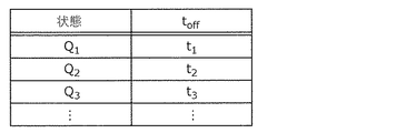
図3は、動作環境ごとのオフ時間を記録したオフ時間テーブルの一例を表す図である。オフ時間テーブル310は、マイクロコンピュータ300のメモリに設けられる。オフ時間テーブル310には、エントリごとに、監視対象の状態Q1、Q2、Q3、…と、当該状態においてオフ時間toffとして用いられる時間t1、t2、t3、…と、を記録している。FIG. 3 is a diagram showing an example of an off-time table in which the off-time for each operating environment is recorded. The off-time table 310 is provided in the memory of the
水素検出装置1における水素検出動作について、詳細な説明を続ける。
A detailed description of the hydrogen detection operation in the
図4は、水素検出動作の詳細な一例を示すフローチャートである。図4では、主として、マイクロコンピュータ300が主体となる動作を詳細に記載している。
FIG. 4 is a flowchart showing a detailed example of the hydrogen detection operation. FIG. 4 mainly describes in detail the operation mainly performed by the
まず、マイクロコンピュータ300において、オン時間tonが設定される(S101)。オン時間tonには、水素センサ100に応じた適宜の固定長が設定されてもよい。First, in the
次に、マイクロコンピュータ300は、状態信号STATUSを取得する(S102)。オフ時間テーブル310が参照され、状態信号STATUSによって表される状態に対応するオフ時間toffが設定される(S103)。
Next, the
次に、マイクロコンピュータ300は、オン時間tonの間、制御信号S0、S1を発行し、センサ制御回路200は、制御信号S0、S1に応じて、水素センサ100に対しセンス電圧VSENSEを印加する(S104、S105)。Next, the
マイクロコンピュータ300は、センス電圧VSENSEの印加中に、検知電圧VDETによって表されるセンス電流があらかじめ定めたしきい値を上回った場合(S106でYES)、水素ガスが検出されたことを示す検出信号DETECTを出力する(S107)。The
オン時間tonの経過後、オフ時間toffが経過するまでの間、マイクロコンピュータ300は制御信号S0を停止し、センサ制御回路200は、制御信号S0の停止に応じて、水素センサ100に対するセンス電圧VSENSEの印加を停止する(S108、S109)。この間、増幅器250への電力供給や、マイクロコンピュータ300のクロックを停止してもよく、水素検出装置1は、消費電力が最小限に抑えられるとしてもよい。After the on-time to- on elapses and until the off-time to- off elapses, the
オフ時間toffの経過後、後続するサイクルの動作がステップS102から繰り返される。After the off time to off elapses, the operation of the subsequent cycle is repeated from step S102.
以上説明したように、水素検出装置1によれば、動作環境に応じて異なるオフ時間を設けて間欠的に水素検出を行うことができる。これにより、例えば、水素漏洩による危険性が高い環境では水素漏洩による危険性が低い環境と比べてオフ時間を短くして高頻度に水素検出を行うといった動作が可能になるので、安全の担保と省電力性とのトレードオフを最適化できる水素検出装置が得られる。
As described above, according to the
(実施の形態2)
[水素センサの構成]
実施の形態2では、実施の形態1で説明した水素検出装置1の水素センサ100として利用可能な気体センサについて説明する。当該気体センサは、本願発明者らによって考案されたものであり、特願2017−169614号(本件出願時において未公開)にて関連特許として出願されている。実施の形態2の説明では、当該関連特許の出願時の明細書の要部を引用する。(Embodiment 2)
[Hydrogen sensor configuration]
In the second embodiment, the gas sensor that can be used as the
実施の形態2に係る気体センサは、金属酸化物層の上下に電極層が積層されてなる構造を基本とする気体センサである。当該気体センサは、少なくとも金属酸化物層の上部の電極層の一部を貫通し、金属酸化物層と上部の電極層との界面を露出させるように形成され、ヒータで加熱することなく水素含有ガスを検出することができる。ここで、水素含有ガスとは、水素原子を有する分子からなる気体の総称であり、一例として、水素、メタン、アルコールなどを含み得る。 The gas sensor according to the second embodiment is a gas sensor based on a structure in which electrode layers are laminated on top and bottom of a metal oxide layer. The gas sensor is formed so as to penetrate at least a part of the electrode layer above the metal oxide layer and expose the interface between the metal oxide layer and the upper electrode layer, and contains hydrogen without heating with a heater. Gas can be detected. Here, the hydrogen-containing gas is a general term for gases composed of molecules having hydrogen atoms, and may include hydrogen, methane, alcohol and the like as an example.
図5Aは、実施の形態2に係る気体センサ100Aの一構成例を示す断面図である。図5Bは、実施の形態2に係る気体センサ100Aの平面図である。図5Aの断面は、図5BのVA−VAの切断線において矢印方向に見た断面に対応する。
FIG. 5A is a cross-sectional view showing a configuration example of the
気体センサ100Aは、基板101、基板101上に形成された絶縁膜102、絶縁膜102の上方に形成された第1電極103、第2電極105、第1電極103と第2電極105とで挟まれた金属酸化物層104、絶縁膜106、ビア107、および配線導体108を備えている。
The
金属酸化物層104は、第1電極103と第2電極105との間に配置されている。金属酸化物層104は、第1電極103と第2電極105との間に印加される電圧および第2電極105が接触する気体中の水素含有ガスの有無に応じて、高抵抗状態と低抵抗状態との間を可逆的に遷移する。
The
絶縁膜106は、第2電極105の上面を覆っている部分において、ビア107が絶縁膜106を貫通して第2電極105に接続されている。ビア107の上に配線導体108が配置されている。
In the insulating
さらに、絶縁膜106および少なくとも第2電極105の一部を貫通するように開口部110が設けられている。図5Bに示すように、開口部110は、平面視したときに気体センサ100Aの中央を含む位置に矩形状に設けられた凹状の窪みである。開口部110の周囲には、図5Aに示すように絶縁膜106が配置されている。なお、開口部110は、平面視した時に気体センサ100Aの中心を含まない位置に設けられてもよいし、矩形状でなくてもよい。第2電極105と金属酸化物層104とが接する界面109が、検査対象である水素含有ガスに接触するよう露出している。界面109は、第1界面である。
Further, an
第2電極105を触媒作用のある金属(例えばPt)で構成すると、図5Cで示すように、開口部110の側面において露出した第2電極105の表面で、水素含有ガスの気体分子112は水素原子113に解離する。また、開口部110によって第2電極105および金属酸化物層104の側面が露出しているため、第2電極105の側面で解離した水素原子113は、第2電極105の表面から金属酸化物層104の側面へと拡散しやすくなっており、第2電極105の側面での新たな解離反応が起こりやすくなり、より多くの水素原子113が発生する。この水素原子113は、第2電極105あるいは金属酸化物層104の表面から内部へと拡散し、金属酸化物層104内で還元反応する。
When the
金属酸化物層104が酸素不足型の金属酸化物である場合、金属酸化物層104は、化学的に不安定であるため水素原子などと反応しやすく、水素原子との反応が促進されることが期待できる。
When the
なお、本開示において、金属酸化物の「酸素不足度」とは、当該金属酸化物と同じ元素から構成される化学量論的組成の酸化物における酸素の量に対する、当該金属酸化物における酸素の不足量の割合をいう。なお、酸素の不足量とは、化学量論的組成の金属酸化物における酸素の量から当該金属酸化物における酸素の量を引いた値である。もし、当該金属酸化物と同じ元素から構成される化学量論的組成の金属酸化物が複数存在しうる場合、当該金属酸化物の酸素不足度は、それらの化学量論的組成の金属酸化物のうち最も高い抵抗値を有する1つに基づいて定義される。化学量論的組成の金属酸化物は、他の組成の金属酸化物と比べて、より安定でありかつより高い抵抗値を有している。 In the present disclosure, the "oxygen deficiency" of a metal oxide is the amount of oxygen in the metal oxide with respect to the amount of oxygen in the oxide having a chemical quantitative composition composed of the same elements as the metal oxide. The ratio of shortage. The amount of oxygen deficiency is a value obtained by subtracting the amount of oxygen in the metal oxide from the amount of oxygen in the metal oxide having a stoichiometric composition. If there can be multiple metal oxides with a chemical composition that are composed of the same elements as the metal oxide, the oxygen deficiency of the metal oxide is determined by the metal oxides with their chemical composition. It is defined based on the one with the highest resistance value. Metal oxides of stoichiometric composition are more stable and have higher resistance values than metal oxides of other compositions.
例えば、金属がタンタル(Ta)の場合、上述の定義による化学量論的組成の酸化物はTa2O5であるので、TaO2.5と表現できる。TaO2.5の酸素不足度は0%であり、TaO1.5の酸素不足度は、酸素不足度=(2.5−1.5)/2.5=40%となる。また、酸素過剰の金属酸化物は、酸素不足度が負の値となる。なお、本明細書中では、特に断りのない限り、酸素不足度は正の値、0、負の値も含むものとして説明する。For example, when the metal is tantalum (Ta), the oxide having a stoichiometric composition according to the above definition is Ta 2 O 5 , so it can be expressed as Ta O 2.5. The oxygen deficiency of TaO 2.5 is 0%, and the oxygen deficiency of TaO 1.5 is oxygen deficiency = (2.5-1.5) /2.5=40%. Further, the oxygen deficiency of the metal oxide having excess oxygen has a negative value. In the present specification, unless otherwise specified, the degree of oxygen deficiency will be described as including positive values, 0, and negative values.
酸素不足度の小さい金属酸化物は化学量論的組成の金属酸化物により近いため抵抗値が高く、酸素不足度の大きい金属酸化物は金属酸化物の構成要素である金属により近いため抵抗値が低い。また、水素原子への解離反応は、第2電極105で生じることから、第2電極105と金属酸化物層104との界面109付近での反応が最も起こりやすいと言える。
A metal oxide with a small oxygen deficiency has a high resistance value because it is closer to a metal oxide having a chemical composition, and a metal oxide with a large oxygen deficiency has a resistance value because it is closer to a metal that is a component of the metal oxide. Low. Further, since the dissociation reaction to the hydrogen atom occurs at the
ここで、気体センサ100Aは、金属酸化物層104の内部に、第2電極105と接するように酸素欠損領域111aを備えていても良い。酸素欠損領域111aは、例えば、開口部110を形成するためのエッチングの際または第2電極105を形成する際などに、金属酸化物層104が受けるエッチングダメージにより発生する酸素欠損領域である。酸素欠損領域111aは、第2電極105と金属酸化物層104との界面付近で第2電極105と金属酸化物層104とが混ざってアモルファス化していても良い。酸素欠損領域111aは、水素含有ガスに接触するよう露出している部分、または、第2電極105と金属酸化物層104との界面109付近に形成されている。
Here, the
また、気体センサ100Aは、金属酸化物層104の内部に、局所領域111bを備えていてもよい。局所領域111bは、第1電極103と第2電極105との間に電圧を印加することによって、金属酸化物層104の一部を絶縁破壊することにより形成される。絶縁破壊された部分の金属酸化物層104は、局所的に酸素が欠損し、電流が流れやすい状態となっている。つまり、局所領域111bは、絶縁破壊による酸素欠損により構成される微小な導電パス(フィラメント)を含む領域である。局所領域111bにおける酸素不足度は、局所領域111bの周囲(すなわち金属酸化物層104のバルク領域)の酸素不足度よりも大きい。
Further, the
局所領域111bを備える気体センサ100Aでは、第1電極103と第2電極105との間に電圧を印加した際、金属酸化物層104内の電流は局所領域111bに集中的に流れる。この構成によれば、気体センサ100Aでは、局所領域111bにおける発熱によって第2電極105が加熱され、水素原子への解離および局所領域111bでの金属酸化物の還元反応が効率よく行われる。
In the
局所領域111bを構成するフィラメントは、気体センサ100Aの1つの金属酸化物層104に1ケ所のみ形成されてもよいし、金属酸化物層104に複数点在していてもよい。フィラメントの数は、例えば、EBAC(Electron Beam Absorbed Current)解析によって確認することができる。
The filaments forming the
このようにして、気体センサ100Aは、第2電極105が水素含有ガスに接すると第1電極103と第2電極105との間の抵抗値が変化する特性を有する。当該特性により、検査対象である気体が気体センサ100Aに接したとき、第1電極103と第2電極105との間の抵抗値の低下を検出することによって、気体に含まれる水素含有ガスを検出することができる。
In this way, the
以下では、安定な水素への反応特性を得るための気体センサ100Aの構成の詳細について説明する。
The details of the configuration of the
金属酸化物層104は、遷移金属を始めとする複数の酸化状態をとることができる金属と、錫と、アルミニウムとからなる群から選択される1つの金属を含有する酸化物から構成される。当該金属の酸化物の母体金属は、タンタル(Ta)、ハフニウム(Hf)、チタニウム(Ti)、ジルコニウム(Zr)、ニオブ(Nb)、タングステン(W)、ニッケル(Ni)、鉄(Fe)、クロム(Cr)、コバルト(Co)、マンガン(Mn)、バナジウム(V)、セリウム(Ce)、銅(Cu)などの遷移金属と、錫(Sn)、アルミニウム(Al)とから少なくとも1つ選択されてもよい。
The
金属酸化物層104は、化学量論的組成の酸化物よりも酸素組成比が少ない酸素不足型の酸化物であってもよい。化学量論的組成の金属酸化物が典型的に絶縁体であるのに対し、酸素不足型の金属酸化物は、酸素欠損を含み半導体的な特性を有する。金属酸化物層104中の酸素欠損は酸素還元反応の活性点となりやすい。つまり水素との反応がしやすくなる。したがって、気体センサ100Aは、安定な水素への反応特性を実現できる。
The
第1電極103および第2電極105の材料としては、例えば、Pt(白金)、Ir(イリジウム)、Pd(パラジウム)、Ag(銀)、Ni(ニッケル)、W(タングステン)、Cu(銅)、Al(アルミニウム)、Ta(タンタル)、Ti(チタン)、TiN(窒化チタン)、TaN(窒化タンタル)およびTiAlN(窒化チタンアルミニウム)などから選択される。
Examples of the materials of the
具体的に、第2電極105は、例えば、白金(Pt)、イリジウム(Ir)、またはパラジウム(Pd)、若しくは、これらのうちの少なくとも1つを含む合金など、水素原子を有する気体分子から水素原子を解離する触媒作用を有する材料で構成する。
Specifically, the
また、第1電極103は、例えば、タングステン(W)、ニッケル(Ni)、タンタル(Ta)、チタン(Ti)、アルミニウム(Al)、窒化タンタル(TaN)、窒化チタン(TiN)など、金属酸化物を構成する金属と比べて標準電極電位が低い材料で構成してもよい。標準電極電位は、その値が高いほど酸化しにくい特性を表す。
Further, the
あるいは第1電極103は、第2電極105と同様に、例えば、白金(Pt)、イリジウム(Ir)、またはパラジウム(Pd)、若しくは、これらのうちの少なくとも1つを含む合金など、水素原子を有する気体分子から水素原子を解離する触媒作用を有する材料で構成してもよい。
Alternatively, the
また、基板101としては、例えば、シリコン単結晶基板または半導体基板を用いることができるが、これらに限定されるわけではない。金属酸化物層104は比較的低い基板温度で形成することが可能であるため、例えば、樹脂材料などの上に形成することもできる。
Further, as the
(実施の形態3)
実施の形態3では、水素検出装置の燃料電池自動車への適用について説明する。実施の形態3に係る水素検出装置は、燃料電池自動車に搭載され、燃料電池自動車における水素漏れを監視する。(Embodiment 3)
In the third embodiment, application of the hydrogen detection device to a fuel cell vehicle will be described. The hydrogen detection device according to the third embodiment is mounted on the fuel cell vehicle and monitors hydrogen leakage in the fuel cell vehicle.
[燃料電池自動車の構成]
図6は、実施の形態3に係る燃料電池自動車800の構成の一例を示す模式図である。[Fuel cell vehicle configuration]
FIG. 6 is a schematic view showing an example of the configuration of the
燃料電池自動車800は、客室810、荷室820、ガスタンク室830、燃料タンク831、水素検出装置832、配管840、燃料電池室850、燃料電池851、水素検出装置852、モータ室860、モータ861、および電子制御ユニット870を備える。
The
燃料タンク831は、ガスタンク室830内に設けられており、燃料ガスとして、水素ガスを保持している。水素検出装置832は、ガスタンク室830での燃料ガス漏れを検出する。
The
燃料電池851は、燃料極、空気極および電解質を有する基本単位となるセルが複数個積み重なった燃料電池スタックを備えている。燃料電池851は、燃料電池室850内に設けられている。燃料タンク831内の水素ガスは、配管840を通して燃料電池室850内の燃料電池851へ送り込まれる。この水素ガスと大気中の酸素ガスとを燃料電池851内で反応させることにより発電する。水素検出装置852は、燃料電池室850での水素ガス漏れを検出する。
The
モータ861は、モータ室860内に設けられている。燃料電池851が発電した電力でモータ861が回転することにより、燃料電池自動車800を走行させる。
The
電子制御ユニット870は、燃料電池851での発電の制御、モータ861のトルク制御、ドライバによるハンドル、アクセル、ブレーキ、ギアシフトなどの各種操作の検知、燃料電池自動車800の速度、加速度の検知など、燃料電池自動車800の総合的な制御を行う。
The
[燃料電池自動車での水素検出動作]
燃料電池自動車800における水素検出装置832、852には、例えば、実施の形態1で説明した水素検出装置1が用いられる。水素検出装置832、852よる水素検出は、次のように行われる。[Hydrogen detection operation in fuel cell vehicles]
For the
電子制御ユニット870は、検知したドライバの操作や燃料電池自動車800の速度などに基づいて、燃料電池自動車800の駐車、停車、走行の各状態を示す状態信号を、水素検出装置832、852へ供給する。ここで、燃料電池自動車800の駐車、停車、走行の各状態は、水素検出装置832、852の動作環境の一例である。
The
水素検出装置832、852は、電子制御ユニット870から供給された状態信号によって示される燃料電池自動車800の状態に応じて異なるオフ時間を設けて、間欠的に水素検出動作を行う。
The
図7Aは、水素検出装置832、852で用いられるオフ時間テーブルの一例を表す図である。
FIG. 7A is a diagram showing an example of an off-time table used in the
図7Aの例では、燃料電池自動車800が走行しているときのオフ時間をt3とし、燃料電池自動車800が駐車しているときのオフ時間をt3より長いt1としている。また、前記燃料電池自動車が停車しているときのオフ時間をt3より長いt2としている。In the example of FIG. 7A, the off-time when the
これにより、水素ガスが燃料電池自動車800内で実際に移送され消費される走行状態では、短いオフ時間t3を用いて水素漏れを高頻度に監視することで、安全をより確実に担保することができる。また、水素ガスの移送および消費が完全に止まっている駐車状態およびほぼ止まっている停車状態では、長いオフ時間t1およびt2を用いて水素漏れの監視頻度を下げることで、安全を担保しながら消費電力を低減し、水素検出装置832、852の省電力性を高めることができる。Thus, the running state of hydrogen gas is actually transported in the
図7Bは、水素検出装置832、852で用いられるオフ時間テーブルの他の一例を表す図である。図7Bのオフ時間テーブルは、図7Aのオフ時間テーブルと比べて、燃料電池自動車800が密閉空間で駐車しているか開放空間で駐車しているかで、オフ時間を区別する点で相違する。
FIG. 7B is a diagram showing another example of the off-time table used in the
ここで、密閉空間とは、水素ガスが充満しやすい空間を意味し、例えば、住宅のビルトインガレージや、公共施設の屋内駐車場およびタワー式の駐車設備が含まれてもよい。開放空間とは、水素ガスが充満しにくい空間を意味し、例えば、住宅のカーポートや公共施設における屋外駐車場および屋上駐車場が含まれてもよい。駐車場所が密閉空間および開放空間のうちのいずれであるかは、駐車設備側から無線信号によって通知されるとしてもよい。 Here, the closed space means a space that is easily filled with hydrogen gas, and may include, for example, a built-in garage of a house, an indoor parking lot of a public facility, and a tower-type parking facility. The open space means a space that is difficult to be filled with hydrogen gas, and may include, for example, an outdoor parking lot and a rooftop parking lot in a carport of a house or a public facility. Whether the parking place is a closed space or an open space may be notified by a wireless signal from the parking facility side.
図7Bの例では、燃料電池自動車800が密閉空間で駐車しているときのオフ時間を走行状態でのオフ時間t3より長いt1bとし、開放空間で駐車しているときのオフ時間をt1bより長いt1aとしている。In the example of FIG. 7B, the off time when the
これにより、駐車状態での水素漏れの監視頻度を、駐車場所において水素漏れが発生した場合の水素の充満のしやすさに応じて設定することにより、安全の担保と省電力性とのトレードオフを最適化することができる。 As a result, the frequency of monitoring hydrogen leaks in the parked state is set according to the ease of hydrogen filling when hydrogen leaks occur in the parking place, which is a trade-off between ensuring safety and power saving. Can be optimized.
(実施の形態4)
実施の形態4では、水素検出装置の、水素ガスを輸送するパイプライン(以下では短く、水素パイプラインと言う)への適用について説明する。実施の形態4に係る水素検出装置は、水素パイプラインに設置され、水素パイプラインにおける水素漏れを監視する。(Embodiment 4)
In the fourth embodiment, the application of the hydrogen detection device to a pipeline for transporting hydrogen gas (hereinafter, shortly referred to as a hydrogen pipeline) will be described. The hydrogen detection device according to the fourth embodiment is installed in a hydrogen pipeline and monitors hydrogen leakage in the hydrogen pipeline.
[水素漏洩監視システムの構成]
図8は、実施の形態4に係る水素漏洩監視システム900の構成の一例を示す模式図である。[Configuration of hydrogen leak monitoring system]
FIG. 8 is a schematic view showing an example of the configuration of the hydrogen
水素漏洩監視システム900は、複合センサモジュール910、通信モジュール920、ゲートウェイ930、クラウドシステム940、およびユーザ端末950を備える。
The hydrogen
複合センサモジュール910は、例えば、実施の形態1で説明した水素検出装置1とともに、監視対象(ここでは、水素パイプライン)の温度、湿度、振動、圧力、および水没のうち少なくとも1つを検出するセンサを含んでいる。複合センサモジュール910(特には、複合センサモジュール910に含まれる水素センサ)は、水素ガス903を輸送する水素輸送管902の上方に配置されている。
The
通信モジュール920は、複合センサモジュール910による水素検出結果を示す検出信号を送信する。
The
ゲートウェイ930は、通信モジュール920から検出信号を受信し、受信した検出信号をクラウドシステム940へ転送する。
The
クラウドシステム940は、サーバ装置をネットワークで接続してなるネットワークコンピュータシステムであり、ネットワークを介してサーバ装置で検出信号を受信し、サーバ装置にて複合センサモジュール910による水素検出結果を集計する。
The
ユーザ端末950は、水素漏洩監視システム900のユーザインターフェースを提供する。具体的には、複合センサモジュール910によって水素が検出されたことを示す警報を、音、光、振動などによってオペレータに通知する。
The
図8の例では、水素輸送管902は地面901下に埋設され、複合センサモジュール910および通信モジュール920は地面901に設けられたハンドホール904内に設置されているが、この例には限られない。例えば、水素輸送管902は、水素関連施設の建屋内に引き回されたものであってもよい。複合センサモジュール910は、例えば、水素輸送管902の継ぎ目(図示せず)ごとに配置されてもよい。
In the example of FIG. 8, the
[複合センサモジュールの構成]
次に、複合センサモジュール910の構成について説明する。[Composite sensor module configuration]
Next, the configuration of the
図9は、複合センサモジュール910の構成の一例を示す模式図である。図9に示されるように、複合センサモジュール910は、水素センサを含む環境センサ911、制御回路913、および電源914を、鋲型の筐体915に格納してなる。複合センサモジュール910は、環境センサ911の一部として水没センサ912をさらに備えていてもよい。
FIG. 9 is a schematic view showing an example of the configuration of the
筐体915は、防水性および防塵性を有するフィルタ916によって第1室917と第2室918とに分けられている。第1室917には、制御回路913および電源914が配置される。第1室917の内部は、筐体915の表面に施されたコート材919とフィルタ916とで、水および埃から保護される。第2室918には、環境センサ911が配置される。第2室918の内部は、少なくとも水素ガスが進入できるように筐体915の外部と連通している。複合センサモジュール910が水没センサ912を備える場合、水没センサ912は、第2室918の内部で、環境センサ911の下方に配置される。
The
環境センサ911は、少なくとも水素センサを含み、さらに、設置環境(ここでは、水素パイプライン)の温度、湿度、振動、圧力、および水没のうち少なくとも1つを検出するセンサを含んでもよい。環境センサ911に含まれる水素センサは、実施の形態1で説明した水素検出装置1の水素センサ100であってもよい。水没センサ912は、複合センサモジュール910の水没を検出する環境センサ911の一例である。
The
制御回路913は、環境センサ911(水素センサを含む)を間欠的に駆動する回路であり、実施の形態1で説明した水素検出装置1のセンサ制御回路200とマイクロコンピュータ300とを含んでもよい。
The
電源914は、図示しないバッテリーおよび電源回路を含み、複合センサモジュール910の全体に動作電力を供給する。
The
[水素漏洩監視システムでの水素検出動作]
水素漏洩監視システム900における複合センサモジュール910による水素検出は、次のように行われる。[Hydrogen detection operation in hydrogen leakage monitoring system]
Hydrogen detection by the
複合センサモジュール910における制御回路913は、環境センサ911を用いて、温度、湿度、振動、および圧力のうち少なくとも1つを測定し、測定値があらかじめ定められた管理範囲内にあれば正常状態、測定値が当該管理範囲を逸脱していれば注意状態と判定する。水没センサ912が設けられていて、かつ水没が検出されていれば、正しい水素検出を行うことができない故障状態と判定してもよい。
The
制御回路913は、判定した状態に応じて異なるオフ時間を設けて、間欠的に水素検出動作を行う。
The
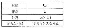
図10は、複合センサモジュール910で用いられるオフ時間テーブルの一例を表す図である。
FIG. 10 is a diagram showing an example of an off-time table used in the
図10の例では、注意状態でのオフ時間をt5とし、正常状態でのオフ時間をt5より長いt4としている。In the example of FIG. 10, the off-time in the attentional state and t 5, it has a off-time of the normal state and longer t 4 from t 5.
これにより、水素パイプラインの温度、湿度、振動、圧力のうち少なくとも1つについて異常値が検出された注意状態では、水素漏洩の危険度が増したと考えて水素漏洩の監視頻度を上げることで、安全をより確実に担保することができる。また、異常値が検出されない正常状態では、水素漏洩の監視頻度を下げることで、安全を担保しながら消費電力を低減し、複合センサモジュール910の省電力性を高めることができる。
As a result, in the caution state where abnormal values are detected for at least one of the temperature, humidity, vibration, and pressure of the hydrogen pipeline, the risk of hydrogen leakage is considered to have increased, and the frequency of monitoring hydrogen leakage is increased. Safety can be guaranteed more reliably. Further, in the normal state in which no abnormal value is detected, the power consumption can be reduced while ensuring safety, and the power saving property of the
また、水没が検出された故障状態では、オフ時間を無限大として、水素検出を停止している。 Further, in the failure state where submersion is detected, hydrogen detection is stopped with the off time set to infinity.
これにより、正しい水素検出を継続して行うことができない場合に、残っている電力を、例えば、故障状態の通報に振り向けることにより、信頼性を高めることができる。 Thereby, when the correct hydrogen detection cannot be continuously performed, the reliability can be improved by allocating the remaining electric power to, for example, reporting the failure state.
(その他の変形例)
以上、本開示のいくつかの態様に係る水素検出装置、燃料電池自動車、水素漏洩監視システム、複合センサモジュール、水素検出方法、およびプログラムについて、実施の形態に基づいて説明したが、本開示は、この実施の形態に限定されるものではない。本開示の趣旨を逸脱しない限り、当業者が思いつく各種変形を本実施の形態に施したものや、各々の実施の形態における構成要素を組み合わせて構築される形態が、本開示の範囲内に含まれてもよい。(Other variants)
The hydrogen detection device, the fuel cell vehicle, the hydrogen leakage monitoring system, the composite sensor module, the hydrogen detection method, and the program according to some aspects of the present disclosure have been described above based on the embodiments. It is not limited to this embodiment. As long as it does not deviate from the purpose of the present disclosure, the scope of the present disclosure includes various modifications that can be conceived by those skilled in the art, and a form constructed by combining the components of each embodiment. It may be.
(実施形態の概要)
1つの態様に係る水素検出装置は、水素ガスの存在に応じて抵抗値が変動する水素センサと、前記水素センサの抵抗値をセンスするセンサ制御回路と、動作環境に応じて異なるオフ時間を設けて前記センサ制御回路を間欠的に駆動するマイクロコンピュータと、を備え、前記水素センサは、第1電極と、前記第1電極上に形成され、水素原子に接することにより抵抗値が変化する金属酸化物層と、前記金属酸化物層上に形成された第2電極と、前記第1電極、前記金属酸化物層および前記第2電極の側面の少なくとも一部を覆う絶縁膜と、を備え、前記金属酸化物層において、前記第1電極と前記金属酸化物層との第1界面もしくは前記第2電極と前記金属酸化物層との第2界面のうちの少なくとも一方の一部は、前記絶縁膜に覆われることなく検出空間に露出している。
(Outline of Embodiment)
The hydrogen detection device according to one embodiment is provided with a hydrogen sensor whose resistance value fluctuates according to the presence of hydrogen gas, a sensor control circuit that senses the resistance value of the hydrogen sensor, and off times that differ depending on the operating environment. The hydrogen sensor is provided on the first electrode and the metal oxidation which is formed on the first electrode and whose resistance value changes when it comes into contact with a hydrogen atom. A material layer, a second electrode formed on the metal oxide layer, and an insulating film covering at least a part of the first electrode, the metal oxide layer, and the side surface of the second electrode are provided. In the metal oxide layer, at least one part of the first interface between the first electrode and the metal oxide layer or the second interface between the second electrode and the metal oxide layer is the insulating film. It is exposed in the detection space without being covered with .
このような構成によれば、金属酸化物層の水素原子による還元反応によって生じる抵抗変化に基づいて水素ガスを検出する水素センサが用いられる。金属酸化物層を還元する水素原子は、検出空間内の水素ガスから解離されたものであり、水素原子への解離は第1界面および第2界面において優勢に生じる。そのため、第1界面および第2界面のうちの少なくとも一方の一部が検出空間に露出している上記の構成によれば、水素原子が効率よく解離され、金属酸化物層の還元反応が進むので、水素ガスの検出特性に優れた水素検出装置が得られる。
また動作環境に応じて異なるオフ時間を設けて間欠的に水素検出を行うこと、つまり、動作環境に応じて異なる頻度で水素検出を行うことができる。これにより、例えば、水素漏洩による危険性が高い環境では水素漏洩による危険性が低い環境と比べてオフ時間を短くして高頻度に水素検出を行うといった動作が可能になるので、安全の担保と省電力性とのトレードオフを最適化できる水素検出装置が得られる。
According to such a configuration, a hydrogen sensor that detects hydrogen gas based on a resistance change caused by a reduction reaction by hydrogen atoms in a metal oxide layer is used. The hydrogen atom that reduces the metal oxide layer is dissociated from the hydrogen gas in the detection space, and the dissociation into the hydrogen atom occurs predominantly at the first interface and the second interface. Therefore, according to the above configuration in which at least one of the first interface and the second interface is exposed in the detection space, hydrogen atoms are efficiently dissociated and the reduction reaction of the metal oxide layer proceeds. , A hydrogen detection device having excellent hydrogen gas detection characteristics can be obtained.
Further , hydrogen detection can be performed intermittently with different off times depending on the operating environment, that is, hydrogen detection can be performed at different frequencies depending on the operating environment. As a result, for example, in an environment where the risk of hydrogen leakage is high, it is possible to perform operations such as shortening the off time and performing hydrogen detection more frequently than in an environment where the risk of hydrogen leakage is low. A hydrogen detection device that can optimize the trade-off with power saving can be obtained.
また、前記第1電極および前記第2電極のうちの少なくとも前記金属酸化物層との界面が前記検出空間に露出している一方は、前記水素原子を有する気体分子から前記水素原子を解離させる触媒作用を有する材料を含んでもよい。 Further, one of the first electrode and the second electrode whose interface with at least the metal oxide layer is exposed in the detection space is a catalyst for dissociating the hydrogen atom from the gas molecule having the hydrogen atom. It may contain a material having an action.
このような構成によれば、前記触媒作用によって気体分子から水素原子が解離され、解離された水素原子が、前記金属酸化物層内の酸素原子と結合することにより、前記第1の電極と前記第2の電極との間の抵抗値が効率よく低下する。これにより、水素ガスの検出特性に優れた水素センサが得られる。 According to such a configuration, a hydrogen atom is dissociated from a gas molecule by the catalytic action, and the dissociated hydrogen atom is bonded to an oxygen atom in the metal oxide layer to form the first electrode and the above. The resistance value between the second electrode and the second electrode is efficiently reduced. As a result, a hydrogen sensor having excellent hydrogen gas detection characteristics can be obtained.
また、前記第1電極および前記第2電極のうちの少なくとも前記一方は、白金を含み、前記金属酸化物層は、タンタル酸化物を含んでもよい。 Further, at least one of the first electrode and the second electrode may contain platinum, and the metal oxide layer may contain tantalum oxide.
このような構成によれば、白金による触媒作用により水素原子を効率的に解離させることができ、かつ、前記金属酸化物層として抵抗変化特性に優れたタンタル酸化物を用いるので、水素含有ガスの検出特性に優れた水素センサが得られる。 According to such a configuration, hydrogen atoms can be efficiently dissociated by the catalytic action of platinum, and tantalum oxide having excellent resistance change characteristics is used as the metal oxide layer. A hydrogen sensor with excellent detection characteristics can be obtained.
また、前記水素検出装置は、燃料電池自動車に搭載され、前記マイクロコンピュータは、前記燃料電池自動車の状態に応じて異なるオフ時間を設けて前記センサ制御回路を間欠的に駆動してもよい。 Further, the hydrogen detection device may be mounted on the fuel cell vehicle, and the microcomputer may intermittently drive the sensor control circuit with different off times depending on the state of the fuel cell vehicle.
このような構成によれば、水素検出装置を燃料電池自動車での水素漏れの監視に利用するに際して、燃料電池自動車の状態に応じた水素漏洩の危険性に基づいて、最適な頻度で水素検出を行うことができるので、安全の担保と省電力性とのトレードオフを最適化できる水素検出装置が得られる。 According to such a configuration, when the hydrogen detection device is used for monitoring hydrogen leakage in a fuel cell vehicle, hydrogen detection is performed at an optimum frequency based on the risk of hydrogen leakage according to the condition of the fuel cell vehicle. Since this can be done, a hydrogen detection device that can optimize the trade-off between ensuring safety and power saving can be obtained.
また、前記マイクロコンピュータは、前記燃料電池自動車が走行しているときのオフ時間をt3とし、前記燃料電池自動車が駐車しているときのオフ時間をt3より長いt1としてもよい。 Further, in the microcomputer, the off time when the fuel cell vehicle is running may be t3, and the off time when the fuel cell vehicle is parked may be t1 longer than t3.
また、前記マイクロコンピュータは、前記燃料電池自動車が密閉空間で駐車しているときのオフ時間をt3より長いt1bとし、開放空間で駐車しているときのオフ時間をt1bより長いt1aとしてもよい。 Further, in the microcomputer, the off time when the fuel cell vehicle is parked in the closed space may be t1b longer than t3, and the off time when the fuel cell vehicle is parked in the open space may be t1a longer than t1b.
また、前記マイクロコンピュータは、前記燃料電池自動車が走行しているときのオフ時間をt3とし、前記燃料電池自動車が停車しているときのオフ時間をt3より長いt2としてもよい。 Further, in the microcomputer, the off time when the fuel cell vehicle is running may be t3, and the off time when the fuel cell vehicle is stopped may be t2 longer than t3.
これらの構成によれば、燃料電池自動車の状態に応じて想定される水素漏洩の具体的な危険性に基づいた頻度で水素検出を行うことができるので、安全の担保と省電力性とのトレードオフを最適化することができる。 According to these configurations, hydrogen can be detected at a frequency based on the specific risk of hydrogen leakage assumed according to the condition of the fuel cell vehicle, so that there is a trade-off between ensuring safety and power saving. Off can be optimized.
また、前記水素検出装置は、水素ガスを輸送するパイプラインに設置され、前記マイクロコンピュータは、前記パイプラインの状態に応じて異なるオフ時間を設けて前記センサ制御回路を間欠的に駆動してもよい。 Further, the hydrogen detection device is installed in a pipeline for transporting hydrogen gas, and the microcomputer may intermittently drive the sensor control circuit with different off-time depending on the state of the pipeline. Good.
このような構成によれば、水素検出装置をパイプラインでの水素漏れの監視に利用するに際して、パイプラインの状態に応じた水素漏洩の危険性に基づいて、最適な頻度で水素検出を行うことができるので、安全の担保と省電力性とのトレードオフを最適化できる水素検出装置が得られる。 According to such a configuration, when the hydrogen detection device is used for monitoring hydrogen leakage in the pipeline, hydrogen detection is performed at an optimum frequency based on the risk of hydrogen leakage according to the state of the pipeline. Therefore, a hydrogen detection device that can optimize the trade-off between ensuring safety and power saving can be obtained.
また、前記マイクロコンピュータは、前記パイプラインにおいて、温度、湿度、振動、圧力のうちの少なくとも1つについて、異常が検出されたときのオフ時間をt5とし、異常が検出されないときのオフ時間をt5より長いt4としてもよい。 Further, in the microcomputer, the off time when an abnormality is detected for at least one of temperature, humidity, vibration, and pressure in the pipeline is t5, and the off time when no abnormality is detected is t5. It may be a longer t4.
この構成によれば、パイプラインの状態に応じて想定される水素漏洩の具体的な危険性に基づいた頻度で水素検出を行うことができるので、安全の担保と省電力性とのトレードオフを最適化することができる。 According to this configuration, hydrogen can be detected at a frequency based on the specific risk of hydrogen leakage that is assumed according to the state of the pipeline, so there is a trade-off between ensuring safety and power saving. Can be optimized.
また、開示される一態様に係る燃料電池自動車は、客室と、水素ガスのタンクが配置されたガスタンク室と、燃料電池が配置された燃料電池室と、前記水素検出装置と、を備え、前記水素検出装置の水素センサが、前記ガスタンク室および前記燃料電池室のうちの少なくとも一方に配置されている。 Further, the fuel cell vehicle according to the disclosed aspect includes a passenger compartment, a gas tank chamber in which a hydrogen gas tank is arranged, a fuel cell chamber in which a fuel cell is arranged, and the hydrogen detection device. The hydrogen sensor of the hydrogen detector is arranged in at least one of the gas tank chamber and the fuel cell chamber.
このような構成によれば、燃料電池自動車において水素漏洩を監視するにあたって、安全の担保と省電力性とのトレードオフを最適化することができる。 With such a configuration, it is possible to optimize the trade-off between ensuring safety and power saving when monitoring hydrogen leakage in a fuel cell vehicle.
また、開示される一態様に係る水素漏洩監視システムは、前記水素検出装置と、前記水素検出装置に接続され、前記水素検出装置による水素検出結果を示す信号を送信する無線モジュールと、前記信号を取得し、前記信号で示される水素検出結果をユーザに提示するユーザ端末と、を備え、前記水素検出装置の水素センサが、水素輸送管の上方に配置されている。 Further, the hydrogen leakage monitoring system according to the disclosed aspect includes the hydrogen detection device, a wireless module connected to the hydrogen detection device and transmitting a signal indicating a hydrogen detection result by the hydrogen detection device, and the signal. acquired, and a user terminal to be presented to the user a hydrogen detection results shown in the previous issue relaxin, the hydrogen sensor of the hydrogen detecting device is arranged above the hydrogen transport tube.
このような構成によれば、水素ガスを輸送するパイプラインにおいて水素漏洩を監視するにあたって、安全の担保と省電力性とのトレードオフを最適化することができる。 With such a configuration, it is possible to optimize the trade-off between ensuring safety and power saving when monitoring hydrogen leakage in a pipeline for transporting hydrogen gas.
また、開示される一態様に係る複合センサモジュールは、前記水素検出装置と、温度、湿度、振動、圧力、水没のうちの少なくとも1つを検出する環境センサと、前記水素検出装置および前記環境センサに動作電力を供給する電源と、を備え、前記マイクロコンピュータは、前記環境センサの検出結果に応じて前記水素検出装置でのオフ時間を変更する。 Further, the composite sensor module according to the disclosed aspect includes the hydrogen detection device, an environment sensor that detects at least one of temperature, humidity, vibration, pressure, and submersion, the hydrogen detection device, and the environment sensor. The microcomputer includes a power source for supplying operating power to the hydrogen detection device, and changes the off time in the hydrogen detection device according to the detection result of the environment sensor.
このような構成によれば、水素漏洩の危険性にかかわる環境要因を自ら検出して、水素漏洩を間欠的に監視するためのオフ時間を決定することができる、利便性に優れた複合モジュールが得られる。 With such a configuration, a highly convenient composite module capable of detecting environmental factors related to the risk of hydrogen leakage by itself and determining the off time for intermittently monitoring hydrogen leakage. can get.
また、開示される一態様に係る水素検出方法は、水素ガスの存在に応じて抵抗値が変動する水素センサを用いた水素検出方法であって、前記水素センサは、第1電極と、前記第1電極上に形成され、水素原子に接することにより抵抗値が変化する金属酸化物層と、前記金属酸化物層上に形成された第2電極と、前記第1電極、前記金属酸化物層および前記第2電極の側面の少なくとも一部を覆う絶縁膜と、を備え、前記金属酸化物層において、前記第1電極と前記金属酸化物層との第1界面もしくは前記第2電極と前記金属酸化物層との第2界面のうちの少なくとも一方の一部は、前記絶縁膜に覆われることなく検出空間に露出しており、前記水素検出方法は、動作環境に応じて異なるオフ時間を設定し、前記水素センサの抵抗値をセンスするセンサ制御回路を、設定された前記オフ時間を設けて間欠的に駆動する。 Further, the hydrogen detection method according to one disclosed aspect is a hydrogen detection method using a hydrogen sensor whose resistance value fluctuates according to the presence of hydrogen gas, and the hydrogen sensor includes a first electrode and the first electrode. A metal oxide layer formed on one electrode and whose resistance value changes upon contact with a hydrogen atom, a second electrode formed on the metal oxide layer, the first electrode, the metal oxide layer, and the like. An insulating film covering at least a part of the side surface of the second electrode is provided, and in the metal oxide layer, the first interface between the first electrode and the metal oxide layer or the second electrode and the metal oxidation At least a part of the second interface with the material layer is exposed to the detection space without being covered with the insulating film, and the hydrogen detection method sets different off times depending on the operating environment. , The sensor control circuit that senses the resistance value of the hydrogen sensor is intermittently driven with the set off time.
このような方法によれば、動作環境に応じて異なるオフ時間を設けて間欠的に水素検出を行うこと、つまり、動作環境に応じて異なる頻度で水素検出を行うことができる。これにより、例えば、水素漏洩による危険性が高い環境では水素漏洩による危険性が低い環境と比べてオフ時間を短くして高頻度に水素検出を行うといった動作が可能になるので、安全の担保と省電力性とのトレードオフを最適化できる水素検出方法が得られる。 According to such a method, hydrogen detection can be performed intermittently with different off times depending on the operating environment, that is, hydrogen detection can be performed at different frequencies depending on the operating environment. As a result, for example, in an environment where the risk of hydrogen leakage is high, it is possible to perform operations such as shortening the off time and performing hydrogen detection more frequently than in an environment where the risk of hydrogen leakage is low. A hydrogen detection method that can optimize the trade-off with power saving can be obtained.
また、開示される一態様に係るプログラムは、水素ガスの存在に応じて抵抗値が変動する水素センサを用いて水素検出を行うためのプログラムであって、前記水素センサは、第1電極と、前記第1電極上に形成され、水素原子に接することにより抵抗値が変化する金属酸化物層と、前記金属酸化物層上に形成された第2電極と、前記第1電極、前記金属酸化物層および前記第2電極の側面の少なくとも一部を覆う絶縁膜と、を備え、前記金属酸化物層において、前記第1電極と前記金属酸化物層との第1界面もしくは前記第2電極と前記金属酸化物層との第2界面のうちの少なくとも一方の一部は、前記絶縁膜に覆われることなく検出空間に露出しており、前記プログラムは、動作環境に応じて異なるオフ時間を設定するステップと、前記水素センサの抵抗値をセンスするセンサ制御回路を、設定された前記オフ時間を設けて間欠的に駆動するステップと、をマイクロコンピュータに実行させる。 Further, the program according to one aspect disclosed is a program for detecting hydrogen using a hydrogen sensor whose resistance value fluctuates according to the presence of hydrogen gas, and the hydrogen sensor includes a first electrode and a first electrode. A metal oxide layer formed on the first electrode and whose resistance value changes upon contact with a hydrogen atom, a second electrode formed on the metal oxide layer, the first electrode, and the metal oxide. A layer and an insulating film covering at least a part of the side surface of the second electrode are provided, and in the metal oxide layer, the first interface between the first electrode and the metal oxide layer or the second electrode and the said. At least a part of the second interface with the metal oxide layer is exposed to the detection space without being covered with the insulating film, and the program sets different off times depending on the operating environment. The microcomputer is made to execute the step and the step of intermittently driving the sensor control circuit that senses the resistance value of the hydrogen sensor with the set off time.
このような構成によれば、安全の担保と省電力性とのトレードオフを最適化できる水素検出方法を実行するためのコンピュータプログラムが得られる。 With such a configuration, a computer program for executing a hydrogen detection method that can optimize the trade-off between ensuring safety and power saving can be obtained.
本開示に係る水素検出装置は、例えば、水素パイプラインをはじめ、燃料電池自動車、水素ステーション、水素プラントなどの水素関連設備において広く利用できる。 The hydrogen detection device according to the present disclosure can be widely used, for example, in hydrogen-related equipment such as a hydrogen pipeline, a fuel cell vehicle, a hydrogen station, and a hydrogen plant.
1 水素検出装置
100A 気体センサ
100 水素センサ
101 基板
102 絶縁膜
103 電極
104 金属酸化物層
105 電極
106 絶縁膜
107 ビア
108 配線導体
109 界面
110 開口部
111a 酸素欠損領域
111b 局所領域
112 気体分子
113 水素原子
200 センサ制御回路
210 電圧パルス発生回路
220 スイッチ
240 抵抗
250 増幅器
300 マイクロコンピュータ
310 オフ時間テーブル
800 燃料電池自動車
810 客室
820 荷室
830 ガスタンク室
831 燃料タンク
832 水素検出装置
840 配管
850 燃料電池室
851 燃料電池
852 水素検出装置
860 モータ室
861 モータ
870 電子制御ユニット
900 水素漏洩監視システム
901 地面
902 水素輸送管
903 水素ガス
904 ハンドホール
910 複合センサモジュール
911 環境センサ
912 水没センサ
913 制御回路
914 電源
915 筐体
916 フィルタ
917 第1室
918 第2室
919 コート材
920 通信モジュール
930 ゲートウェイ
940 クラウドシステム
950 ユーザ端末1
Claims (14)
前記水素センサの抵抗値をセンスするセンサ制御回路と、
動作環境に応じて異なるオフ時間を設けて前記センサ制御回路を間欠的に駆動するマイクロコンピュータと、
を備え、
前記水素センサは、
第1電極と、
前記第1電極上に形成され、水素原子に接することにより抵抗値が変化する金属酸化物層と、
前記金属酸化物層上に形成された第2電極と、
前記第1電極、前記金属酸化物層および前記第2電極の側面の少なくとも一部を覆う絶縁膜と、を備え、
前記金属酸化物層において、前記第1電極と前記金属酸化物層との第1界面もしくは前記第2電極と前記金属酸化物層との第2界面のうちの少なくとも一方の一部は、前記絶縁膜に覆われることなく検出空間に露出している、
水素検出装置。 A hydrogen sensor whose resistance value fluctuates according to the presence of hydrogen gas,
A sensor control circuit that senses the resistance value of the hydrogen sensor and
A microcomputer that intermittently drives the sensor control circuit with different off times depending on the operating environment, and
Equipped with a,
The hydrogen sensor is
With the first electrode
A metal oxide layer formed on the first electrode and whose resistance value changes when it comes into contact with a hydrogen atom.
The second electrode formed on the metal oxide layer and
The first electrode, the metal oxide layer, and an insulating film covering at least a part of the side surface of the second electrode are provided.
In the metal oxide layer, at least one part of the first interface between the first electrode and the metal oxide layer or the second interface between the second electrode and the metal oxide layer is insulated. Exposed to the detection space without being covered by the membrane,
Hydrogen detector.
請求項1に記載の水素検出装置。 One of the first electrode and the second electrode, at least one of which has an interface with the metal oxide layer exposed in the detection space, has a catalytic action of dissociating the hydrogen atom from the gas molecule having the hydrogen atom. Including materials to have,
The hydrogen detection device according to claim 1.
前記金属酸化物層は、タンタル酸化物を含む、
請求項2に記載の水素検出装置。 At least one of the first electrode and the second electrode contains platinum and contains platinum.
The metal oxide layer contains tantalum oxide.
The hydrogen detection device according to claim 2.
前記マイクロコンピュータは、前記燃料電池自動車の状態に応じて異なるオフ時間を設けて前記センサ制御回路を間欠的に駆動する、
請求項1から3のいずれか1項に記載の水素検出装置。 The hydrogen detection device is mounted on a fuel cell vehicle and is mounted on a fuel cell vehicle.
The microcomputer intermittently drives the sensor control circuit with different off times depending on the state of the fuel cell vehicle.
The hydrogen detection device according to any one of claims 1 to 3.
請求項4に記載の水素検出装置。 In the microcomputer, the off time when the fuel cell vehicle is running is t3, and the off time when the fuel cell vehicle is parked is t1 which is longer than t3.
The hydrogen detection device according to claim 4.
請求項5に記載の水素検出装置。 In the microcomputer, the off time when the fuel cell vehicle is parked in a closed space is t1b longer than t3, and the off time when the fuel cell vehicle is parked in an open space is t1a longer than t1b.
The hydrogen detection device according to claim 5.
請求項4に記載の水素検出装置。 In the microcomputer, the off time when the fuel cell vehicle is running is t3, and the off time when the fuel cell vehicle is stopped is t2, which is longer than t3.
The hydrogen detection device according to claim 4.
前記マイクロコンピュータは、前記パイプラインの状態に応じて異なるオフ時間を設けて前記センサ制御回路を間欠的に駆動する、
請求項1から3のいずれか1項に記載の水素検出装置。 The hydrogen detector is installed in a pipeline that transports hydrogen gas.
The microcomputer intermittently drives the sensor control circuit with different off times depending on the state of the pipeline.
The hydrogen detection device according to any one of claims 1 to 3.
請求項8に記載の水素検出装置。 The microcomputer sets the off time when an abnormality is detected as t5 and the off time when no abnormality is detected for at least one of temperature, humidity, vibration, and pressure in the pipeline to be longer than t5. Let it be t4
The hydrogen detection device according to claim 8.
水素ガスのタンクが配置されたガスタンク室と、
燃料電池が配置された燃料電池室と、
請求項4から7のいずれか1項に記載の水素検出装置と、を備え、
前記水素検出装置の水素センサが、前記ガスタンク室および前記燃料電池室のうちの少なくとも一方に配置されている、
燃料電池自動車。 Rooms and
The gas tank room where the hydrogen gas tank is located and
The fuel cell room where the fuel cell is located and
The hydrogen detection device according to any one of claims 4 to 7 is provided.
The hydrogen sensor of the hydrogen detector is arranged in at least one of the gas tank chamber and the fuel cell chamber.
Fuel cell vehicle.
前記水素検出装置に接続され、前記水素検出装置による水素検出結果を示す信号を送信する無線モジュールと、
前記信号を取得し、前記信号で示される水素検出結果をユーザに提示するユーザ端末と、を備え、
前記水素検出装置の水素センサが、水素輸送管の上方に配置されている、
水素漏洩監視システム。 The hydrogen detection device according to claim 8 or 9,
A wireless module connected to the hydrogen detection device and transmitting a signal indicating a hydrogen detection result by the hydrogen detection device, and
Acquiring the signal, and a user terminal to be presented to the user a hydrogen detection results shown in the previous issue relaxin,
The hydrogen sensor of the hydrogen detection device is arranged above the hydrogen transport pipe.
Hydrogen leak monitoring system.
温度、湿度、振動、圧力、水没のうちの少なくとも1つを検出する環境センサと、
前記水素検出装置および前記環境センサに動作電力を供給する電源と、を備え、
前記マイクロコンピュータは、前記環境センサの検出結果に応じて前記水素検出装置でのオフ時間を変更する、
複合センサモジュール。 The hydrogen detection device according to any one of claims 1 to 3.
An environment sensor that detects at least one of temperature, humidity, vibration, pressure, and submersion,
The hydrogen detection device and the power source for supplying operating power to the environment sensor are provided.
The microcomputer changes the off time in the hydrogen detection device according to the detection result of the environment sensor.
Composite sensor module.
前記水素センサは、
第1電極と、
前記第1電極上に形成され、水素原子に接することにより抵抗値が変化する金属酸化物層と、
前記金属酸化物層上に形成された第2電極と、
前記第1電極、前記金属酸化物層および前記第2電極の側面の少なくとも一部を覆う絶縁膜と、を備え、
前記金属酸化物層において、前記第1電極と前記金属酸化物層との第1界面もしくは前記第2電極と前記金属酸化物層との第2界面のうちの少なくとも一方の一部は、前記絶縁膜に覆われることなく検出空間に露出しており、
前記水素検出方法は、
動作環境に応じて異なるオフ時間を設定し、
前記水素センサの抵抗値をセンスするセンサ制御回路を、設定された前記オフ時間を設けて間欠的に駆動する、
水素検出方法。 It is a hydrogen detection method using a hydrogen sensor whose resistance value fluctuates according to the presence of hydrogen gas.
The hydrogen sensor is
With the first electrode
A metal oxide layer formed on the first electrode and whose resistance value changes when it comes into contact with a hydrogen atom.
The second electrode formed on the metal oxide layer and
The first electrode, the metal oxide layer, and an insulating film covering at least a part of the side surface of the second electrode are provided.
In the metal oxide layer, at least one part of the first interface between the first electrode and the metal oxide layer or the second interface between the second electrode and the metal oxide layer is insulated. It is exposed in the detection space without being covered by the film,
The hydrogen detection method is
Set different off time according to the operating environment,
The sensor control circuit that senses the resistance value of the hydrogen sensor is intermittently driven with the set off time.
Hydrogen detection method.
前記水素センサは、
第1電極と、
前記第1電極上に形成され、水素原子に接することにより抵抗値が変化する金属酸化物層と、
前記金属酸化物層上に形成された第2電極と、
前記第1電極、前記金属酸化物層および前記第2電極の側面の少なくとも一部を覆う絶縁膜と、を備え、
前記金属酸化物層において、前記第1電極と前記金属酸化物層との第1界面もしくは前記第2電極と前記金属酸化物層との第2界面のうちの少なくとも一方の一部は、前記絶縁膜に覆われることなく検出空間に露出しており、
前記プログラムは、
動作環境に応じて異なるオフ時間を設定するステップと、
前記水素センサの抵抗値をセンスするセンサ制御回路を、設定された前記オフ時間を設けて間欠的に駆動するステップと、
をマイクロコンピュータに実行させるプログラム。 This is a program for detecting hydrogen using a hydrogen sensor whose resistance value fluctuates according to the presence of hydrogen gas.
The hydrogen sensor is
With the first electrode
A metal oxide layer formed on the first electrode and whose resistance value changes when it comes into contact with a hydrogen atom.
The second electrode formed on the metal oxide layer and
The first electrode, the metal oxide layer, and an insulating film covering at least a part of the side surface of the second electrode are provided.
In the metal oxide layer, at least one part of the first interface between the first electrode and the metal oxide layer or the second interface between the second electrode and the metal oxide layer is insulated. It is exposed in the detection space without being covered by the film,
The program
Steps to set different off times depending on the operating environment,
A step of intermittently driving the sensor control circuit that senses the resistance value of the hydrogen sensor with the set off time.
A program that causes a microcomputer to execute.
Applications Claiming Priority (3)
| Application Number | Priority Date | Filing Date | Title |
|---|---|---|---|
| US201662434686P | 2016-12-15 | 2016-12-15 | |
| US62/434,686 | 2016-12-15 | ||
| PCT/JP2017/044108 WO2018110441A1 (en) | 2016-12-15 | 2017-12-08 | Hydrogen detecting device, fuel cell vehicle, hydrogen leak monitoring system, compound sensor module, hydrogen detecting method, and program |
Publications (2)
| Publication Number | Publication Date |
|---|---|
| JPWO2018110441A1 JPWO2018110441A1 (en) | 2019-10-24 |
| JP6840170B2 true JP6840170B2 (en) | 2021-03-10 |
Family
ID=62558717
Family Applications (1)
| Application Number | Title | Priority Date | Filing Date |
|---|---|---|---|
| JP2018556633A Active JP6840170B2 (en) | 2016-12-15 | 2017-12-08 | Hydrogen detectors, fuel cell vehicles, hydrogen leak monitoring systems, composite sensor modules, hydrogen detection methods, and programs |
Country Status (5)
| Country | Link |
|---|---|
| US (1) | US11027604B2 (en) |
| EP (1) | EP3557236B1 (en) |
| JP (1) | JP6840170B2 (en) |
| CN (1) | CN110088608B (en) |
| WO (1) | WO2018110441A1 (en) |
Families Citing this family (9)
| Publication number | Priority date | Publication date | Assignee | Title |
|---|---|---|---|---|
| CN110657920B (en) * | 2019-08-23 | 2021-04-27 | 武汉格罗夫氢能汽车有限公司 | Method for detecting concentration of hydrogen in vehicle based on T-BOX |
| CN110658303B (en) * | 2019-08-23 | 2021-04-23 | 武汉格罗夫氢能汽车有限公司 | T-BOX-based in-vehicle hydrogen concentration detection processing method |
| CN111376797B (en) * | 2020-03-24 | 2021-10-29 | 东风汽车集团有限公司 | Hydrogen leakage detection control method and system for hydrogen fuel cell automobile |
| JP7365288B2 (en) | 2020-04-10 | 2023-10-19 | 株式会社東芝 | Sensors and sensor modules |
| JP7340489B2 (en) | 2020-04-10 | 2023-09-07 | 株式会社東芝 | Sensors and sensor modules |
| CN112895900B (en) * | 2021-01-08 | 2022-08-19 | 株洲中车时代电气股份有限公司 | Hydrogen energy tramcar hydrogen redundancy monitoring protection device and method |
| CN113312380B (en) * | 2021-07-29 | 2022-01-07 | 湖南五凌电力科技有限公司 | Method and device for automatically acquiring vibration region of hydroelectric generating set based on data driving |
| FR3136897A1 (en) * | 2022-06-20 | 2023-12-22 | Arm Engineering | UNIVERSAL FUEL CELL SYSTEM |
| CN115230476B (en) * | 2022-08-05 | 2023-05-12 | 兰州现代职业学院 | Fuel cell automobile detection circuit and method |
Family Cites Families (49)
| Publication number | Priority date | Publication date | Assignee | Title |
|---|---|---|---|---|
| GB2085166A (en) * | 1980-10-07 | 1982-04-21 | Itt Ind Ltd | Semiconductor gas sensor |
| JPS61172025A (en) * | 1984-12-13 | 1986-08-02 | Caterpillar Mitsubishi Ltd | Gas leakage detection and recording apparatus |
| US5321146A (en) * | 1991-03-29 | 1994-06-14 | Eastman Kodak Company | Hydrogen sulfide gas sensor and precursor compounds for manufacture of same |
| US5428988A (en) * | 1993-12-13 | 1995-07-04 | Trw Vehicle Safety Systems Inc. | Leak detector for gas air bag inflator |
| JPH09229598A (en) | 1996-02-23 | 1997-09-05 | Toray Ind Inc | Blade protection material and blade protection cloth |
| DE19618935C2 (en) * | 1996-05-10 | 2002-11-28 | Siemens Ag | Gas sensor and method for manufacturing a gas sensor |
| JP3792016B2 (en) | 1997-08-26 | 2006-06-28 | 新コスモス電機株式会社 | Gas leak alarm |
| JP3518800B2 (en) * | 1999-12-16 | 2004-04-12 | フィガロ技研株式会社 | Gas sensor and gas detection device |
| US6401465B1 (en) * | 2000-10-19 | 2002-06-11 | Carrier Corporation | Absorption chiller leak detection and location and checking hydrogen removing cells |
| JP2002310978A (en) * | 2001-04-12 | 2002-10-23 | Ngk Spark Plug Co Ltd | Hydrogen sensor |
| US7235171B2 (en) * | 2001-07-24 | 2007-06-26 | Matsushita Electric Industrial Co., Ltd. | Hydrogen sensor, hydrogen sensor device and method of detecting hydrogen concentration |
| JP2003240746A (en) * | 2002-02-14 | 2003-08-27 | Matsushita Electric Ind Co Ltd | Hydrogen gas sensor |
| US20060263255A1 (en) * | 2002-09-04 | 2006-11-23 | Tzong-Ru Han | Nanoelectronic sensor system and hydrogen-sensitive functionalization |
| JP2004139842A (en) * | 2002-10-17 | 2004-05-13 | Nissan Motor Co Ltd | Hydrogen leakage detecting system of fuel cell vehicle |
| JP4187506B2 (en) * | 2002-11-07 | 2008-11-26 | 新コスモス電機株式会社 | Package type fuel cell power generator |
| US6786076B2 (en) * | 2002-11-25 | 2004-09-07 | Reliable Instruments Llc | Thin film gas sensor |
| TW586007B (en) * | 2003-02-13 | 2004-05-01 | Univ Nat Cheng Kung | Hydrogen sensor and fabrication method thereof |
| JP4310736B2 (en) * | 2003-10-20 | 2009-08-12 | スズキ株式会社 | Hydrogen leak detection device for vehicles equipped with fuel cell system |
| JP4056987B2 (en) * | 2004-04-28 | 2008-03-05 | アルプス電気株式会社 | Hydrogen sensor and hydrogen detection method |
| JP2006010622A (en) * | 2004-06-29 | 2006-01-12 | Honda Motor Co Ltd | Gas detection system and fuel cell vehicle |
| JP2006084335A (en) * | 2004-09-16 | 2006-03-30 | Fujikura Ltd | Concentration cell type oxygen sensor |
| JP2006098343A (en) * | 2004-09-30 | 2006-04-13 | Tdk Corp | Gas sensor |
| JP2006118939A (en) * | 2004-10-20 | 2006-05-11 | Riken Keiki Co Ltd | Gas sensor |
| JP3945714B2 (en) * | 2004-11-26 | 2007-07-18 | 株式会社日立製作所 | Radio terminal with gas leak detection function, gas leak detection system using the same, and gas leak notification method |
| JP5105218B2 (en) * | 2005-06-06 | 2012-12-26 | トヨタ自動車株式会社 | Abnormality judgment device |
| JP4806989B2 (en) * | 2005-07-27 | 2011-11-02 | トヨタ自動車株式会社 | Fuel cell system |
| US7268662B2 (en) * | 2005-09-07 | 2007-09-11 | Applied Sensor Research & Development Corporation | Passive SAW-based hydrogen sensor and system |
| US8636883B2 (en) * | 2006-03-10 | 2014-01-28 | Element One, Inc. | Monitorable hydrogen sensor system |
| JP4789666B2 (en) * | 2006-03-23 | 2011-10-12 | 能美防災株式会社 | Gas pipeline monitoring equipment |
| KR100779090B1 (en) * | 2006-07-18 | 2007-11-27 | 한국전자통신연구원 | Gas sensor using zinc oxide and method of forming the same |
| EP2083262B1 (en) * | 2008-01-28 | 2014-05-07 | Micronas GmbH | Resistive hydrogen sensor |
| US8499612B2 (en) * | 2009-04-23 | 2013-08-06 | The Regents Of The University Of California | Hydrogen gas detection using single palladium nanowires |
| FR2950740A1 (en) * | 2009-09-25 | 2011-04-01 | Michelin Soc Tech | ELECTROCHEMICAL REACTOR, SUCH AS A FUEL CELL OR ELECTROLYSER, EQUIPPED WITH A DEVICE FOR MEASURING THE CONCENTRATION IN A GAS OF ONE OF THE SPECIFIC GASES OF THE OPERATION OF SAID REACTOR |
| US20110088456A1 (en) * | 2009-10-16 | 2011-04-21 | Fan Ren | Normalized hydrogen sensing and methods of fabricating a normalized hydrogen sensor |
| US9310240B2 (en) | 2011-03-22 | 2016-04-12 | Seiko Epson Corporation | Circuit device, integrated circuit and detection device |
| JP6019603B2 (en) | 2012-02-13 | 2016-11-02 | セイコーエプソン株式会社 | Circuit device, integrated circuit, and detection device |
| WO2012130751A1 (en) * | 2011-03-25 | 2012-10-04 | Odb-Tec Gmbh & Co. Kg | Diode thin film assembly for detecting hydrogen and method for the production thereof, and hydrogen sensor |
| JP5342602B2 (en) * | 2011-05-20 | 2013-11-13 | 本田技研工業株式会社 | Gas sensor |
| KR20140118020A (en) * | 2013-03-27 | 2014-10-08 | 인텔렉추얼디스커버리 주식회사 | Hydrogen gas sensor and method for manufacturing the same |
| JP6256933B2 (en) * | 2013-05-23 | 2018-01-10 | 木村 光照 | Hydrogen gas sensor having concentration function and hydrogen gas sensor probe used therefor |
| CN104981688B (en) * | 2013-05-29 | 2018-07-13 | 罗斯蒙特分析公司 | Stink damp bulk detector with humidity and temperature-compensating |
| US20150171437A1 (en) * | 2013-12-12 | 2015-06-18 | GM Global Technology Operations LLC | Layer design to mitigate fuel cell electrode corrosion from non-ideal operation |
| KR101649586B1 (en) * | 2014-04-07 | 2016-08-19 | 주식회사 모다이노칩 | Senser |
| KR101683977B1 (en) * | 2014-08-21 | 2016-12-20 | 현대자동차주식회사 | hydrogen sensor and method for manufacturing the same |
| CN104391013A (en) * | 2014-10-30 | 2015-03-04 | 中国电子科技集团公司第四十八研究所 | Nitrogen-doped titanium dioxide nanotube hydrogen sensor and preparation method thereof |
| CN108112263B (en) * | 2015-08-28 | 2020-11-03 | 松下半导体解决方案株式会社 | Gas sensor and fuel cell vehicle |
| JP6764239B2 (en) | 2016-03-18 | 2020-09-30 | シャープ株式会社 | Hair dryer |
| KR101906153B1 (en) * | 2016-03-31 | 2018-10-11 | 한양대학교 에리카산학협력단 | Thermochemical gas sensor based on thermoelectric thin film and manufacturing method thereof |
| US10112486B2 (en) * | 2016-09-21 | 2018-10-30 | Hyundai Motor Company | Apparatus for detecting gas leakage of a vehicle equipped with a fuel cell system |
-
2017
- 2017-12-08 EP EP17881397.8A patent/EP3557236B1/en active Active
- 2017-12-08 CN CN201780076755.1A patent/CN110088608B/en active Active
- 2017-12-08 US US16/468,558 patent/US11027604B2/en active Active
- 2017-12-08 WO PCT/JP2017/044108 patent/WO2018110441A1/en unknown
- 2017-12-08 JP JP2018556633A patent/JP6840170B2/en active Active
Also Published As
| Publication number | Publication date |
|---|---|
| EP3557236A4 (en) | 2020-01-15 |
| EP3557236B1 (en) | 2020-11-04 |
| CN110088608A (en) | 2019-08-02 |
| CN110088608B (en) | 2021-06-08 |
| JPWO2018110441A1 (en) | 2019-10-24 |
| WO2018110441A1 (en) | 2018-06-21 |
| US20200083549A1 (en) | 2020-03-12 |
| EP3557236A1 (en) | 2019-10-23 |
| US11027604B2 (en) | 2021-06-08 |
Similar Documents
| Publication | Publication Date | Title |
|---|---|---|
| JP6840170B2 (en) | Hydrogen detectors, fuel cell vehicles, hydrogen leak monitoring systems, composite sensor modules, hydrogen detection methods, and programs | |
| JP6145762B1 (en) | Gas sensor and fuel cell vehicle | |
| US10591432B2 (en) | Hydrogen detection method using gas sensor having a metal oxide layer | |
| JP7027340B2 (en) | Manufacturing methods for gas sensors, gas detectors, fuel cell vehicles and gas sensors | |
| JP6761764B2 (en) | Hydrogen sensor and fuel cell vehicle, and hydrogen detection method | |
| JP6873160B2 (en) | Gas detectors, gas detector systems, fuel cell vehicles, and gas detection methods | |
| US11933752B2 (en) | Gas sensor and fuel cell vehicle | |
| US20210389264A1 (en) | Gas sensor, method of manufacturing gas sensor, and fuel cell vehicle | |
| KR102009059B1 (en) | Sensor and method for manufacturing a sensor | |
| CA2872236C (en) | Methods and apparatus for measuring the total organic content of aqueous streams | |
| KR20110100361A (en) | Noxious gas sensor, method for detection | |
| KR20160063092A (en) | A gas sensing module and that of detection method for gases | |
| JP4310736B2 (en) | Hydrogen leak detection device for vehicles equipped with fuel cell system | |
| JP2008101923A (en) | Electrochemical sensor | |
| JP2004170147A (en) | Carbon monoxide gas sensor element and carbon monoxide gas detector | |
| JP2006343353A (en) | Gas concentration detector | |
| JP2022012739A (en) | Gas sensor device | |
| JP2019109183A (en) | Semiconductor type gas detection element | |
| JPH0941177A (en) | Electrochemical element, electrochemical treatment using the same and device for electrochemical treatment |
Legal Events
| Date | Code | Title | Description |
|---|---|---|---|
| A521 | Request for written amendment filed |
Free format text: JAPANESE INTERMEDIATE CODE: A523 Effective date: 20190524 |
|
| A711 | Notification of change in applicant |
Free format text: JAPANESE INTERMEDIATE CODE: A711 Effective date: 20200217 |
|
| A711 | Notification of change in applicant |
Free format text: JAPANESE INTERMEDIATE CODE: A711 Effective date: 20200520 |
|
| A621 | Written request for application examination |
Free format text: JAPANESE INTERMEDIATE CODE: A621 Effective date: 20200709 |
|
| TRDD | Decision of grant or rejection written | ||
| A01 | Written decision to grant a patent or to grant a registration (utility model) |
Free format text: JAPANESE INTERMEDIATE CODE: A01 Effective date: 20210202 |
|
| A61 | First payment of annual fees (during grant procedure) |
Free format text: JAPANESE INTERMEDIATE CODE: A61 Effective date: 20210216 |
|
| R150 | Certificate of patent or registration of utility model |
Ref document number: 6840170 Country of ref document: JP Free format text: JAPANESE INTERMEDIATE CODE: R150 |
|
| R250 | Receipt of annual fees |
Free format text: JAPANESE INTERMEDIATE CODE: R250 |