JP6840066B2 - Leakage detection system and leak detection method - Google Patents
Leakage detection system and leak detection method Download PDFInfo
- Publication number
- JP6840066B2 JP6840066B2 JP2017224751A JP2017224751A JP6840066B2 JP 6840066 B2 JP6840066 B2 JP 6840066B2 JP 2017224751 A JP2017224751 A JP 2017224751A JP 2017224751 A JP2017224751 A JP 2017224751A JP 6840066 B2 JP6840066 B2 JP 6840066B2
- Authority
- JP
- Japan
- Prior art keywords
- water leakage
- vibration
- data
- terminal
- center
- Prior art date
- Legal status (The legal status is an assumption and is not a legal conclusion. Google has not performed a legal analysis and makes no representation as to the accuracy of the status listed.)
- Active
Links
Images


Landscapes
- Pipeline Systems (AREA)
- Examining Or Testing Airtightness (AREA)
Description
本発明は漏水検知システムおよび漏水検知方法に関し、例えば埋設管の漏水を検知する漏水検知システムおよび漏水検知方法に適用して好適なものである。 The present invention relates to a water leakage detection system and a water leakage detection method, and is suitable for being applied to, for example, a water leakage detection system and a water leakage detection method for detecting water leakage in a buried pipe.
水道局等の上水道事業者は、広範囲の配水区に対して水道サービスを提供している。日本国内では、高度成長期に配水設備が設置されてから60年が経過し、配水設備の老朽化が進行している。そこで、耐震化を含めた更新事業を行っているが、いずれの事業体でも漏水が多発している現状がある。また、水道事業は、人口減少にともなう使用水量の減少による減収、事業職員数の減少の事業課題があり、有収水量を改善する漏水対策に関する効率的な解決策が求められている。 Water supply companies such as the Waterworks Bureau provide water services to a wide range of distribution areas. In Japan, 60 years have passed since the water distribution equipment was installed during the period of high economic miracle, and the water distribution equipment is aging. Therefore, we are conducting renewal projects including earthquake resistance, but the current situation is that water leaks occur frequently in all of the entities. In addition, the water supply business has business issues such as a decrease in revenue due to a decrease in the amount of water used due to the declining population and a decrease in the number of business staff, and an efficient solution for water leakage countermeasures to improve the amount of revenue water is required.
ここで、水道管路の漏水を検知する漏水探知機の種類および探知方法に関しては、「水道維持管理指針2006」に開示されている(非特許文献1参照)。その中で位置推定も可能な探知方式として、相関式の漏水発見装置がある。この種類の漏水発見装置では、漏水地点を含む水道管路の2箇所に探査用のセンサを設置し、相関器により各センサまでの漏水音および振動の伝播時間差を求め、伝播時間差、センサ間の距離、および管路を伝播する音波の伝播速度より漏水箇所を発見する。 Here, the types and detection methods of water leak detectors for detecting water leaks in water pipes are disclosed in "Water Supply Maintenance Guideline 2006" (see Non-Patent Document 1). Among them, there is a correlation type leak detection device as a detection method capable of estimating the position. In this type of leak detection device, sensors for exploration are installed at two locations in the water pipe including the leak point, and the propagation time difference between the leakage sound and vibration to each sensor is calculated by the correlator, and the propagation time difference and the sensors are used. Find the leak point from the distance and the propagation speed of the sound wave propagating in the pipeline.
また、放送電波受信回路を設置し、各測定地点で漏洩音検出器より入力される漏洩音検出信号とともに放送受信信号を記録し、記録終了後、両装置の記録データを照合し、放送受信信号を基準として記録時間差を補正した上で、相関演算を行う方法が開示されている(特許文献1参照)。 In addition, a broadcast radio wave reception circuit is installed to record the broadcast reception signal together with the leak sound detection signal input from the leak sound detector at each measurement point, and after the recording is completed, the recorded data of both devices are collated and the broadcast reception signal is collated. Disclosed is a method of performing a correlation calculation after correcting a recording time difference with reference to (see Patent Document 1).
これまで漏水に関しては、担当職員が現地に赴き、移動式の漏水探知機を使用して個別に漏水箇所の探査を行い、漏水箇所を特定し、その後の工事作業を計画していた。広範囲のサービスエリアを巡回して漏水調査を実施することは、維持管理のコスト面でも効率的ではない。今後の効率的な漏水対策方法として、広範囲に多地点の水道埋設管に安価なセンシング端末を配置し、遠隔監視により漏水の発生を検出し、高精度な漏水点位置の推定が行える監視システムを提供することが考えられる。 Until now, regarding water leaks, the staff in charge went to the site, searched for the leak points individually using a mobile leak detector, identified the leak points, and planned the subsequent construction work. It is not efficient in terms of maintenance cost to carry out a leak survey by visiting a wide range of service areas. As an efficient water leakage countermeasure method in the future, a monitoring system that can detect the occurrence of water leakage by remote monitoring and estimate the location of the water leakage point with high accuracy by arranging inexpensive sensing terminals in a wide range of water supply buried pipes. It is possible to provide it.
センシング端末のデータ通信方式としては、低電力無線通信LPWA(Low Power Wide Access)の活用が有効と考えられる。しかしながら、通信網の仕様上の制約により、センシング端末間の時間同期が十分な精度で行えない場合がある。例えば、LPWAの1つであるLoRaアライアンスが規格化したLoRaWAN規格では、通信モードによっては時刻同期の信号を受け取ることができない。また、長期間にわたる電池駆動で動作するための省電力運転のために、センシング端末は、通常動作モードと電力をほとんど消費しない休止モードとを繰り返す動作となるために、時間同期が不正確となる。漏水検知に使用する相関法では、正確な時間同期が必要となるため、正確な時間同期が必要となる。 As a data communication method for sensing terminals, it is considered effective to utilize low power wireless communication LPWA (Low Power Wide Access). However, due to restrictions on the specifications of the communication network, time synchronization between sensing terminals may not be possible with sufficient accuracy. For example, in the LoRaWAN standard standardized by the LoRa Alliance, which is one of LPWA, it is not possible to receive a time synchronization signal depending on the communication mode. In addition, due to power-saving operation for long-term battery-powered operation, the sensing terminal repeats the normal operation mode and the hibernation mode that consumes almost no power, so that the time synchronization becomes inaccurate. .. The correlation method used for leak detection requires accurate time synchronization, so accurate time synchronization is required.
本発明は以上の点を考慮してなされたもので、漏水検知端末間の時間同期をとることができる漏水検知システム等を提案しようとするものである。 The present invention has been made in consideration of the above points, and an object of the present invention is to propose a water leakage detection system or the like capable of time synchronization between water leakage detection terminals.
かかる課題を解決するため本発明においては、埋設管の漏水を検知するための複数の漏水検知端末と、前記複数の漏水検知端末の各々と通信網を介して接続されるセンタ側装置とを備える漏水検知システムであって、前記複数の漏水検知端末の各々は、埋設管内の振動を検知するセンサ部と、前記センサ部で検知した振動の振動データを処理する端末側処理部と、前記端末側処理部の処理結果を前記センタ側装置に送信する端末側通信部と、を備え、前記センタ側装置は、前記複数の漏水検知端末の各々から送信された処理結果を受信するセンタ側通信部と、前記処理結果を処理するセンタ側処理部と、前記センタ側処理部で処理されたデータに含まれる漏水の振動データとは異なる振動データに基づいて、前記複数の漏水検知端末のうち近接して設置されている漏水検知端末間の時刻同期を行う時刻同期部と、を設けるようにした。 In order to solve such a problem, the present invention includes a plurality of leak detection terminals for detecting leaks in the buried pipe, and a center-side device connected to each of the plurality of leak detection terminals via a communication network. In the water leakage detection system, each of the plurality of water leakage detection terminals includes a sensor unit that detects vibration in the buried pipe, a terminal side processing unit that processes vibration data of vibration detected by the sensor unit, and the terminal side. A terminal-side communication unit that transmits the processing result of the processing unit to the center-side device, and the center-side device includes a center-side communication unit that receives the processing result transmitted from each of the plurality of water leakage detection terminals. , The center-side processing unit that processes the processing result and the leakage detection terminal among the plurality of leakage detection terminals are close to each other based on vibration data different from the leakage vibration data included in the data processed by the center-side processing unit. A time synchronization unit that synchronizes the time between the installed leak detection terminals is provided.
また本発明においては、埋設管の漏水を検知するための複数の漏水検知端末と、前記複数の漏水検知端末の各々と通信網を介して接続されるセンタ側装置とを備える漏水検知システムにおける漏水検知方法であって、前記複数の漏水検知端末の各々が、埋設管内の振動を検知し、検知した振動の振動データを処理した処理結果を前記センタ側装置に送信する第1のステップと、前記センタ側装置が、前記複数の漏水検知端末の各々から送信された処理結果を受信し、前記処理結果を処理し、処理したデータに含まれる漏水の振動データとは異なる振動データに基づいて、前記複数の漏水検知端末のうち近接して設置されている漏水検知端末間の時刻同期を行う第2のステップと、を設けるようにした。 Further, in the present invention, water leakage in a water leakage detection system including a plurality of water leakage detection terminals for detecting water leakage in a buried pipe and a center-side device connected to each of the plurality of water leakage detection terminals via a communication network. In the detection method, each of the plurality of water leakage detection terminals detects the vibration in the buried pipe, and the first step of transmitting the processing result of processing the vibration data of the detected vibration to the center side device, and the above-mentioned The center-side device receives the processing results transmitted from each of the plurality of water leakage detection terminals, processes the processing results, and uses vibration data different from the water leakage vibration data included in the processed data. A second step of synchronizing the time between the leak detection terminals installed close to each other among the plurality of leak detection terminals is provided.
上記構成によれば、漏水検知端末で検知された振動の振動データに含まれる漏水の振動データとは異なる振動データに基づいて漏水検知端末間の時刻同期を行うことができる。 According to the above configuration, time synchronization between the water leakage detection terminals can be performed based on the vibration data different from the water leakage vibration data included in the vibration data of the vibration detected by the water leakage detection terminal.
本発明によれば、信頼性の高い漏水検知システム等を実現することができる。 According to the present invention, a highly reliable water leakage detection system or the like can be realized.
以下図面について、本発明の一実施の形態を詳述する。 Hereinafter, one embodiment of the present invention will be described in detail with reference to the drawings.
(1)第1の実施の形態
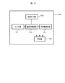
図1において、1は全体として第1の実施の形態による漏水探知システムを示す。漏水探知システム1は、複数の漏水検知端末100と、センタ側装置120とを含んで構成される。各漏水検知端末100とセンタ側装置120とは、通信網110を介して通信可能に接続される。かかる漏水探知システム1では、広範囲の埋設管に漏水検知端末100が配置され、遠隔監視により漏水の発生を検出し、高精度な漏水点の位置推定が可能である。以下では、その詳細について主に説明する。
(1) First Embodiment In FIG. 1, 1 indicates a leak detection system according to the first embodiment as a whole. The leak detection system 1 includes a plurality of
漏水検知端末100は、センサ部101、端末側処理部102、端末側通信部103、および電池部104を備える。センタ側装置120は、センタ側通信部121、センタ側処理部122、時刻同期部123、表示装置124、および管路網データベース125を備える。
The water
漏水検知端末100は、上水道のサービス圏内の配水区の埋設管(配水管、水道管)各所に分散して配置されるものである。センサ部101は、埋設管内の振動を検出し、振動データに変換する。端末側処理部102は、FFT(ファスト・フーリエ変換処理)等の周波数解析手法により振動データを周波数データに変換する。端末側通信部103は、通信網110を介して、周波数データをセンタ側装置120に転送する。電池部104は、漏水検知端末100の電力供給手段であり、漏水検知端末100の各部に電力を供給する。
The
なお、漏水検知端末100の機能(例えば、端末側処理部102)は、図示しないCPU(Central Processing Unit)がメモリにプログラムを読み出して実行すること(ソフトウェア)に実現されてもよいし、回路などのハードウェアにより実現されてもよいし、ソフトウェアとハードウェアが組み合わされて実現されてもよい。 The function of the water leakage detection terminal 100 (for example, the terminal side processing unit 102) may be realized by a CPU (Central Processing Unit) (not shown) reading a program into a memory and executing it (software), a circuit, or the like. It may be realized by the hardware of, or it may be realized by a combination of software and hardware.
図2は、漏水検知端末100の設置例を示す図である。図2には、マンホール蓋201、埋設管網に設置された仕切弁202、埋設管203、埋設管203上の地表面204が示されている。漏水検知端末100は、マンホール蓋201が開かれ、マンホール内の仕切弁202の弁キャップ部分(仕切弁202を開閉するための操作部)に取り付けられ、埋設管203内の水を伝播する振動を検出する。
FIG. 2 is a diagram showing an installation example of the water
漏水検知端末100は、上述のように仕切弁202の弁キャップ部分(設置箇所の一例)に設置され、長期間電池のみで動作しなければならないため、通信手段(端末側通信部103と通信網110)としては、低消費電力の方式で、数キロメートルの配水区を伝達できる方式を採用する。そのような通信網として、低電力無線通信網(LPWA)が挙げられ、そのLPWAの通信サービスの1つとして、LoRaWAN規格が今後の有力サービスの候補である。
Since the water
漏水検知端末100は、省電力のため、通常モードと休止モードとの2つの動作モードを持ち、2つの動作モードを自動的に切り替えて動作する。この制御は、端末側処理部102により実行される。通常モードは、漏水を検知するための動作モードであり、比較的電力を消費する動作モードであり、休止モードは、デジタル処理のクロック周波数を下げるなどして、ほとんど電力を消費しない動作モードである。運用の一例として、漏水検知端末100は、外部ノイズが少ない深夜に毎日通常モードで動作し、埋設管の振動データを収集し、センタ側装置120にデータを転送する。それ以外の時間帯については、漏水検知端末100は、休止モードで動作し、次の通常モードまで待機している。
The water
上水道のサービス圏内の漏水検知端末100全体については、同一時刻にデータ収集を実行するいくつかのグループに分類して運用する。LPWAのサービス仕様上、漏水検知端末100は、秒単位では合わされているが、ミリ秒単位の精度では時刻同期が取られていないことを前提とする。同一時刻にデータ収集を実行することを、センタ側装置120から上記グループ内の各漏水検知端末100に要求する、または事前にプログラムすることにより、グループ内の漏水検知端末100の取得したデータのデータ収集時間の大部分が重なるようにする。かかる構成により、センタ側装置120の計算処理で漏水検知端末100間のデータの相関が計算可能となる。上記グループの漏水検知端末100の数は、通信網110の設計に依存する。つまり、全体で1つのグループとなるか、または設置位置の近い漏水検知端末100を集めた複数のグループとなる。グループの管理は、センタ側装置120の処理に任される。
The entire
センタ側装置120は、通信網110を介して、複数の漏水検知端末100と通信を行う。センタ側通信部121は、漏水検知端末100の設定パラメータ等のデータを送信データとして送信すると共に、漏水検知端末100が送信した周波数変換された振動データ(周波数データ)を受信する。
The center-
漏水検知端末100の送信データには、時刻同期に関するデータが含まれている場合があるが、そのデータからは漏水検知端末100の送信データについて、十分な精度で時刻同期が取れない場合が予想される。この段階で想定される時刻同期の精度の一例としては、測定期間が30秒程度に対して、時刻同期の誤差が1秒程度である。漏水検知端末100間のデータの相関を計算するためには、ミリ秒単位、または入力データのサンプリングレートの時間間隔が必要である。
The transmission data of the water
センタ側処理部122は、近接(隣接でもよい。)する漏水検知端末100を2つ選択し、データ間の相関などを計算する。センタ側処理部122は、その計算において、時刻同期部123が実行する時間軸補正処理(観測地点2点のセンサ同期をとるための処理)により、漏水検知端末100が送信したデータの時間軸を補正する。センタ側処理部122の処理結果は、管路網データベース125より読み出した埋設管の管路図に重畳して表示装置124により表示される。表示装置124は、カラーの画像表示装置であり、センタ側処理部122による処理結果に係る表示を行う。例えば、表示装置124は、対象の2つの漏水検知端末100について、その間の埋設管上に漏水が検知された場合は、埋設管上の対応する位置に、赤色等の際立つ色、点滅、パターン等による漏水発生の表示を行う。表示装置124の表示例については後述する(図7参照)。
The center-
なお、センタ側装置120の機能(例えば、センタ側処理部122、時刻同期部123)は、図示しないCPUがメモリにプログラムを読み出して実行すること(ソフトウェア)に実現されてもよいし、回路などのハードウェアにより実現されてもよいし、ソフトウェアとハードウェアが組み合わされて実現されてもよい。
The functions of the center-side device 120 (for example, the center-
図3は、漏水検知端末100の構成要素である端末側処理部102の構成の一例を示す図である。端末側処理部102は、データ入力部301、スペクトル解析部302、学習部303、対数尤度算出部304、設定パラメータ入力部305、閾値比較部306、出力部307、スペクトル中間データ生成部308、バッファ部309、および出力部310を備える。
FIG. 3 is a diagram showing an example of the configuration of the terminal-
センサ部101が取得した振動データは、データ入力部301より入力され、スペクトル解析部302で周波数解析が行われる。スペクトル解析部302は、埋設管の振動データとして一定の周波数範囲を対象として、パワースペクトル(電力スペクトル)の計算を行う。周波数範囲の一例は、埋設管の漏水現象に関係する信号周波数として、直流成分から1000Hz程度の範囲である。したがって、センサ部101の標本周波数(サンプリング周波数)としては2キロヘルツ、またはそれ以上の周波数を使用する。なお、パワースペクトルは、埋設管内の振動状態を現し、時間と共に変化するため、一定の時間間隔で逐次算出される。
The vibration data acquired by the
学習部303は、パワースペクトルについてモデルベースの学習または機械学習を実行する。例えば、学習部303は、予め設定された基本的なモデルパラメータを基に設置箇所に特有(例えば、自動販売機の振動)のモデルパラメータを学習する。学習モデルの一例として、GMMモデル(Gaussian Mixture Model)があり、正常時および漏水時(異常時)のパワースペクトルを学習させる。漏水時の学習が実施困難である場合は正常時のみの学習でもよい。その学習結果は、モデルパラメータ(または特徴量)としてデータ化して学習部303の内部に保持する。モデルパラメータは、必要に応じて、センタ側装置120に送信され、センタ側装置120の管路網データベース125に追加(記憶)して管理されるようにしてもよい。
The
なお、設置場所毎に、最初から学習を行うことに困難がある場合は、予め実験的な施設で取得した学習結果(モデルパラメータ)を、学習部303に外部から設定してもよい。
If it is difficult to perform learning from the beginning for each installation location, the learning result (model parameter) acquired in advance at the experimental facility may be set in the
対数尤度算出部304は、逐次入力されるパワースペクトルと学習した正常時モデルのパワースペクトルおよび漏水時モデルのパワースペクトルとの間の複合的な対数尤度(モデルパラメータとパワースペクトルとの類似度を示すデータ)を算出する。なお、閾値比較部306は、対数尤度と後述の閾値とを比較して漏水の有無(正常時であるか異常時であるか)を識別する。
The log-
閾値比較部306は、対数尤度算出部304の算出結果と、設定パラメータ入力部305から入力される閾値とを逐次比較し、漏水が発生しているか否かの推定結果を示す2値の信号、すなわち、漏水判定結果を出力する。その信号(比較結果)は、出力部307より出力されると同時に、通信用のバッファ部309への制御信号として入力される。制御信号により、漏水発生している推定時と通常時とで、送信データのデータ内容を切り替えることが可能となる。
The threshold
スペクトル中間データ生成部308は、データ入力部301から入力される振動データを処理し、相関法等の解析を行う周波数解析用のスペクトル中間データ(中間データ)を生成する。中間データの一例として、FFTスペクトル係数の複素係数データが挙げられる。複素係数データを用いることで、振幅の情報に加えて、位相情報を含めることができる。スペクトル中間データ生成部308の出力情報は、バッファ部309に入力され、一時蓄積される。
The spectrum intermediate
バッファ部309は、漏水判定結果、対数尤度、中間データの各データを入力とし、それらをバッファ(図示は省略)に一時蓄積する。バッファ部309は、出力部310を介してセンタ側通信部121と接続され、送信用バッファの動作を担う。
The
データ送信の一例として、漏水検知端末100は、漏水判定結果により漏水が発生していると推定される場合は、対数尤度の情報および中間データを内部に格納し、出力部310より出力する。一方、漏水検知端末100は、漏水判定結果が漏水発生なしと推定する場合は、対数尤度および中間データは入力されるものの、送信データ内容には含めず、出力部310からは漏水判定結果のみを出力する。これにより、送信データの容量を少なく抑えることができ、結果として漏水検知端末100の消費電力を節約することができる。漏水が検出されるタイミングと中間データが生成されるタイミングとは同時ではないため、一時的にバッファ部309によりデータが蓄積され、送信が実行されるときにバッファ部309によりバッファからの読み出しが行われる。
As an example of data transmission, when it is estimated that water leakage has occurred based on the water leakage determination result, the water
ここで、中間データとしては、周波数の全範囲または部分的な周波数範囲に対応するデータが選択され、センタ側装置120に送信される。部分的な周波数範囲に制限する理由は、通信データ容量の削減である。かかる構成により、通信網110の仕様に合致させると同時に、消費電力を低減し、電池交換期間を長期化することができる。
Here, as the intermediate data, data corresponding to the entire or partial frequency range of the frequency is selected and transmitted to the
図4は、部分的な周波数範囲の一例を示す図である。ここでは、2つの周波数の組み合わせ(周波数範囲)を示しているが、3つ以上を使用することも可能である。図4では、周波数f1から始まる周波数の組み合わせ401、周波数f2から始まる周波数の組み合わせ402を示す。周波数の組み合わせ401と周波数の組み合わせ402との周波数範囲が重なり範囲をもつことも許容される。また、周波数の組み合わせでは、周波数が連続している必要はなく、離散的であってもよい。なお、部分的な周波数範囲(周波数の組み合わせ)は、配管の太さ、種類などの管路条件によって周波数帯が変わるものであり、漏水探知システム1の設計段階で求められるものである。
FIG. 4 is a diagram showing an example of a partial frequency range. Here, a combination of two frequencies (frequency range) is shown, but it is also possible to use three or more. FIG. 4 shows a
これら周波数の組み合わせに対応した周波数の中間データが送信され、センタ側装置120でデータ処理される。なお、周波数の組み合わせ401、周波数の組み合わせ402は、センタ側装置120で識別される周波数の組み合わせである。
Intermediate data of frequencies corresponding to these combinations of frequencies is transmitted, and data processing is performed by the
第1の周波数の組み合わせは、埋設管の振動に含まれる背景信号の周波数に対応するものであり、第2の周波数の組み合わせは、埋設管の振動の漏水現象に付随する周波数に対応するものとする。付言するならば、背景信号は、工場、線路などの大型設備からの振動を示す振動信号、川などによる振動を示す振動信号などである。 The first frequency combination corresponds to the frequency of the background signal included in the vibration of the buried pipe, and the second frequency combination corresponds to the frequency associated with the water leakage phenomenon of the vibration of the buried pipe. To do. In addition, the background signal is a vibration signal indicating vibration from a large facility such as a factory or a railroad track, a vibration signal indicating vibration from a river, or the like.
図5は、センタ側処理部122と時刻同期部123との両方を含むセンタ側装置120の構成の一例を示す図である。センタ側処理部122および時刻同期部123が実行するセンタ側漏水検知処理について説明する。
FIG. 5 is a diagram showing an example of the configuration of the center-
センタ側装置120は、端末データ選択部501、周波数選択部502、逆FFT部503、相互相関関数算出部504、ピーク時間算出部505、周波数選択部506、逆FFT部507、相互相関関数算出部508、ピーク時間算出部509、差分算出部510、出力部511、モデル学習部512、漏水判定部513、出力部514、および表示処理部515を備える。
The
端末データ選択部501は、管路網データベース125に格納(記憶)された位置情報に基づいて、近接する2つの漏水検知端末100の送信データの組を選択し、入力を行う。入力されたデータの組のそれぞれについて、周波数選択部502は、周波数の選択を行う。この周波数の選択では、図4で説明した周波数の組み合わせのうち、背景信号に対応する第1の周波数の組み合わせが選択される。
The terminal
周波数選択部502で選択されたデータについて、逆FFT部503は、フーリエ逆変換により時間ドメインの波形データに復元処理する。
The
逆FFT部503により、近接する2つの漏水検知端末100のそれぞれの波形データが復元されるので、その波形データの組について、相互相関関数算出部504は、相互相関関数を計算する処理を実行する。相互相関関数においては、一定の遅延時間を持って同じ現象を観測したデータ系列については、その遅延時間に相当する時間差の点で相関値がピークを持つ特性がある。
Since the waveform data of each of the two adjacent water
ここで、近接する2つの漏水検知端末100の背景信号については、同じタイミングでセンサ部101に到達して観測されるが、漏水検知端末100の処理系により、データに遅延時間(時刻ずれ)を含んでいる。よって、ピーク時間算出部505は、相互相関関数のピーク時間を算出し、時刻ずれを出力する。なお、周波数選択部502、逆FFT部503、相互相関関数算出部504、およびピーク時間算出部505の処理(破線で囲った範囲の処理)が、時刻同期部123の処理に対応する部分の一例である。
Here, the background signals of the two adjacent water
周波数選択部506は、端末データ選択部501から入力する近接する2つの漏水検知端末100のデータから第2の周波数の組み合わせ、すなわち、漏水現象に対応する周波数を選択し、逆FFT部507に通知する。
The
周波数選択部506で選択されたデータについて、逆FFT部507は、フーリエ逆変換により時間ドメインの波形データに復元処理する。
The
逆FFT部507により、近接する2つの漏水検知端末100のそれぞれの波形データが復元されるので、その波形データの組について、相互相関関数算出部508は、相互相関関数を計算する処理を実行する。その計算結果は、2つの波形データの時間差に対する相関値であり、相互相関関数算出部504との違いは、対象の波形データが漏水現象に対応する漏水信号、すなわち、漏水成分である点である。
Since the waveform data of each of the two adjacent water
ピーク時間算出部509で相互相関関数のピーク時間を算出することにより、漏水成分の遅延時間が求まる。ここで求めた遅延時間は、差分算出部510により、ピーク時間算出部505の出力である時刻ずれの量が減算され、出力部511により出力される。出力部511で出力される値は、選択した近接する2つの漏水検知端末100の観測結果に基づく、漏水成分の伝播遅延時間である。
By calculating the peak time of the cross-correlation function by the peak
図6に示すように、漏水が発生している漏水地点601が選択された2つの漏水検知端末602,603の間にある場合、伝播遅延時間は、漏水地点601からの振動波形の伝播時間の差(時間差t)となる。時間差tと水中の振動波形の伝播速度(管内音速)cとより、漏水地点601から近い方の漏水検知端末602までの距離Lを下記の(数式1)より推定することができる。ここで、2つの漏水検知端末602,603の距離は、Dとする。
As shown in FIG. 6, when the
![]()
![]()
漏水地点601が2つの漏水検知端末602,603間の外である場合、伝播遅延時間は、2つの漏水検知端末602,603間を伝播する時間となる。この場合、計算上は、L=0に相当し、信号が早く到達する漏水検知端末602または漏水検知端末603と同じ位置で漏水が発生している場合と同様となる。この場合の関係式は、(数式2)となる。
When the
![]()
![]()
管内音速cは、配管604の種類、水質、水圧、温度などの条件により変化するが、漏水を発見した漏水検知端末602,603の組の隣の漏水検知端末100のデータから(数式2)により、管内音速cの補正に関する情報を導くことができる。(数式2)を用いて求めた管内音速cをc1とした場合、その管内音速に基づく漏水地点601までの距離L1は(数式3)となる。
The sound velocity c in the pipe changes depending on the type of
![]()
![]()
(数式1)のLと(数式3)のL1の差分ΔLを求め、漏水地点601までの推定距離の誤差とみなすことができる。
The difference ΔL between L in (Formula 1) and L1 in (Formula 3) can be obtained and regarded as an error in the estimated distance to the
![]()
![]()
このように、標準的な音速cと測定した音速c1とからΔLを求めることにより、例えば、漏水工事の際に誤差を考慮して掘削することができるようになる。なお、センタ側装置120は、近接する2つの漏水検知端末100の組み合わせ全ての処理結果を表示する。
By obtaining ΔL from the standard sound velocity c and the measured sound velocity c1 in this way, for example, excavation can be performed in consideration of an error during water leakage work. The center-
モデル学習部512は、相互相関関数算出部508から入力される時刻同期前の漏水成分に関する相関データ、および、出力部511からの時刻同期後の伝播遅延時間の2種類の情報について、正常モデルからの距離を算出し、それを出力する。モデル学習の一例は、GMMであり、その場合の距離は対数尤度である。
The
漏水判定部513は、算出された距離を所定の閾値と比較することにより、漏水の発生の有無を判定し、その判定結果(漏水判定結果)を出力部514より出力する。
The water
漏水判定結果は、表示処理部515で表示用の処理が実行され、表示装置124に表示される。ここでの表示用の処理とは、表示装置124の入力形式に合わせた変換であり、具体的には画像への変換処理である。
The water leakage determination result is displayed on the
図7は、センタ側装置120の表示装置124における表示例を示す図である。図7では、表示処理部515が処理した結果の画像イメージの一部分のみを拡大表示したものが示されている。符号を付したものは、画像イメージ中の各要素であり、埋設管表示700、漏水検知端末表示701A,701B,701C、漏水検知端末100の識別番号表示702A,702B,702C、漏水度表示703A,703B,703C、漏水検知端末100の漏水状態表示704A,704B,704C、漏水検知端末100の時刻同期状態表示705A,705B,705C、漏水発生の位置表示706である。なお、3つの漏水検知端末100のそれぞれに対応して、A、B、Cの符号を付加している。
FIG. 7 is a diagram showing a display example in the
表示装置124は、管路網データベース125を読み出して、管路図を地図上に重畳して表示するものであり、図7に示す画像イメージがさらに重畳して描かれることにより、地図上の地点と埋設管の状態とを対応付けて確認することができる。図7には示していないが、必要に応じて、背景部分に地図情報としての道路、建物などが描かれてもよい。
The
図7では、埋設管表示700に接続する3つの漏水検知端末表示701A,701B,701Cが、その識別番号表示702A,702B,702Cと共に示されている。漏水検知端末100単体で判定した単体の漏水度(漏水の発生度合いに関するデータの一例)は、漏水度表示703A,703B,703Cで数値表示される。さらに、それを3段階のレベルで表示する部分が漏水状態表示704A,704B,704Cであり、左からレベル「低」、「中」、「高」の表示となる。低中高の順番で漏水の発生度合いが高まることを意味する。この3レベルについては、色、形などを変えることにより、区別しやすくすることも考えられる。
In FIG. 7, three leak
時刻同期状態表示705A,705B,705Cは、その漏水検知端末100を含む近接の漏水検知端末100間で時刻同期が正常に処理されているかの状態を示すものである。時刻同期が正常でない場合、相関法に基づく漏水点までの距離推定は正しく行えない可能性が高いことに留意する。なお、時刻同期が正常に処理されているか否かの判定方法については、後述の第3の実施の形態において説明する。
The time synchronization status displays 705A, 705B, and 705C indicate a state in which time synchronization is normally processed between nearby
位置表示706は、漏水検知端末100間(漏水検知端末表示701A,701B)の配管上に検出した漏水点の位置を示している。地図上の距離関係を反映した位置に、位置表示706が設けられる。
The
図8は、管路網データベース125のデータ内容の一例を示す図である。管路網データベース125は、埋設管の管路網に関するデータを保持するデータベースであり、管路網情報801、管種Aパラメータ802、管種Bパラメータ803、管種Cパラメータ804、端末設定パラメータ805を含んで構成される。ここでは、3種類の埋設管について、符号A,B,Cを対応させて記載しているが、対応する管種の数により増減する。管種として、例えば、Aは、鋳鉄管、Bは、ダクタイル鋳鉄管、Cは、塩化ビニール管に対応するなどが考えられる。管の内径、外形、厚みなどの要素で管種を増やしてもよい。
FIG. 8 is a diagram showing an example of the data contents of the
管路網情報801は、配水区の埋設管に関する管種情報、位置情報、埋設場所の情報(地上面の条件、高度、埋設土壌の条件を含む)、埋設管に接続している止水弁、制水弁など配水制御施設に関するデータ、マンホールの位置情報、設置した漏水検知端末100全てに対応した設置位置とその運用状況とに関するデータである。それらのデータには、設置条件に加えて、観測した動作状態(たとえば、流量、水圧等)も含まれる。
The
管種Aパラメータ802、管種Bパラメータ803、および管種Cパラメータ804の各々は、周波数の組み合わせに係る設定パラメータであり、管種に対応する漏水検知端末100の設定パラメータに関する代表データである。
Each of the pipe
端末設定パラメータ805は、設置した漏水検知端末100が使用する設定パラメータであり、全ての漏水検知端末100の個々に対応した設定パラメータを独立したデータとして保持する。
The
漏水検知端末100の運用開始時に、センタ側処理部122は、例えば、管路網情報801に基づいて管種に対応した管種パラメータ(802,803,804)のうちの1つを選択して端末設定パラメータ805に設定する。なお、端末設定パラメータ805は、センタ側通信部121を介して漏水検知端末100に送信され、漏水検知端末100(端末側処理部102)は、端末側通信部103を介して受信した端末設定パラメータ805を設定する。端末設定パラメータ805は、漏水検知端末100の運用に伴い、適宜変更される。
At the start of operation of the
図9は、漏水検知端末100が実行する端末側漏水検知処理に係るフローチャートの一例を示す図である。
FIG. 9 is a diagram showing an example of a flowchart relating to a terminal-side leak detection process executed by the
端末側処理部102は、所定のタイミング(センタ側装置120からの指示、プログラムされた時刻など)で端末側漏水検知処理を開始する(ステップS901)。
The terminal-
続いて、端末側処理部102は、漏水検知端末100単体での漏水度(単体漏水度)を算出する(ステップS902)。単体漏水度は、対数尤度算出部304の出力である対数尤度の値に対応する。なお、単体漏水度は、時系列データであり、所定の観測時間に渡る複数個のデータからなるデータ列である。
Subsequently, the terminal-
続いて、端末側処理部102は、単体漏水度と設定された閾値との比較を行う(ステップS903)。端末側処理部102は、単体漏水度が閾値を超えると判定した場合、ステップS904に処理を移し、単体漏水度が閾値を超えないと判定した場合、ステップS905に処理を移す。なお、端末側処理部102は、単体漏水度が時系列データであるので、観測時間内のデータの中央値または平均値を代表値として閾値との比較を行う。
Subsequently, the terminal-
ステップS904では、端末側処理部102は、単体漏水度およびスペクトル中間データを端末側通信部103を介してセンタ側装置120に送信する。
In step S904, the terminal-
ステップS905では、端末側処理部102は、単体漏水度のみを端末側通信部103を介してセンタ側装置120に送信する。
In step S905, the terminal-
ステップS906では、端末側処理部102は、端末側漏水検知処理を終了する。
In step S906, the terminal-
本実施の形態によれば、漏水検知端末100を埋設管の止水弁等、設置可能な位置に分散して配置し、無線通信により、その状態を一定間隔(毎日の定刻時など)で送信し、センタ側装置120で受信したデータを集約し、個別の埋設管に関して詳細に分析し、サービス圏内を網羅的に遠隔監視することができる。
According to the present embodiment, the water
また、漏水検知端末100が送信するデータに含まれる時刻同期の不正確さは時刻同期部123の働きにより除去されるため、相関法による高精度な漏水位置までの距離推定が可能となる。
Further, since the inaccuracy of time synchronization included in the data transmitted by the water
また、漏水の発生状況は、管路図と共に表示され、水道管管理に有効な情報を提示することができる。 In addition, the occurrence status of water leakage is displayed together with the pipeline diagram, and useful information for water pipe management can be presented.
また、時刻同期処理のためにセンサ部101の検出信号を使用するため、特別な同期処理のための装置を追加することなく、マンホール内に漏水検知端末100を設置した通常の運用状態で目的の時刻同期処理を実行することができる。
Further, since the detection signal of the
(2)第2の実施の形態
本実施の形態では、システム運用の継続をチェックでき、漏水検知端末100の配置変更に伴う設置ミスをチェックできるシステム構成について説明する。例えば、漏水検知端末100の設置作業により、近隣の漏水検知端末100の位置を取り違えることは起こり得ることであり、それを確認する手段はシステム運用において重要である。
(2) Second Embodiment In this embodiment, a system configuration capable of checking the continuation of system operation and checking an installation error due to a change in the arrangement of the
センタ側装置120の構成は、図1と同じであるが、その処理内容が異なる。処理内容については、図10に示すフローチャートを用いて後述する。
The configuration of the center-
漏水検知端末100の構成については、設置ミスの確認手法に応じて、2通りの構成を例に挙げて説明する。第1の確認手法では、振動発生器1102を追加した漏水検知端末1100を用い、漏水検知端末1100の構成の一例を図11に示す。第2の確認手法では、図1の漏水検知端末100の構成と同一のものを用いる。また、第1の確認手法に対応した漏水検知端末1100が実行する処理に係るフローチャートの一例を図12に示し、第2の確認手法に対応した漏水検知端末100が実行する処理に係るフローチャートの一例を図13に示す。
The configuration of the
なお、第1の確認手法によれば、センタ側装置120からの命令でいつでも確認を開始することができるが、第2の確認手法によれば、作業者が現場で漏水検知端末100の設置時に、漏水検知端末100を設置した付近で打音等の特別な振動を発生させる必要がある。以下、詳細について説明する。
According to the first confirmation method, the confirmation can be started at any time by a command from the
図10は、第1の確認手法における、センタ側装置120が実行する漏水検知端末1100の設置位置の確認に関する確認処理に係るフローチャートの一例を示す図である。
FIG. 10 is a diagram showing an example of a flowchart relating to a confirmation process relating to confirmation of the installation position of the water
センタ側処理部122は、所定のタイミング(定期的、指定時刻、管理者からの指示など)で確認処理を開始する(ステップS1001)。
The center-
まず、センタ側処理部122は、確認端末(漏水検知端末100および/または漏水検知端末1100)としてN個(集合)を選択する(ステップS1002)。ここで、Nは、設置位置を確認する確認端末の個数であり、3以上の数である。
First, the center-
続いて、センタ側処理部122は、確認端末N個のデータから近接する2つずつの中間データの組をつくり、時刻同期部123は、それぞれで時刻同期処理を行い、N個すべての時刻同期処理を完了する(ステップS1003)。時刻同期処理の方法は、第1の実施の形態と同様であり、第1の周波数の組み合わせによる方法を用いる。
Subsequently, the center-
続いて、センタ側処理部122は、後述する第3の周波数の組み合わせについて、集合内の近接する2つの確認端末のデータ間(振動検知時間)の時間差を求める(ステップS1004)。ここで求める時間差は、ステップS1003で算出した時刻同期による補正を含めた値とする。センタ側処理部122は、確認端末N個に関して、近接する2つの確認端末の組み合わせすべてについて、上記の処理を行い、各確認端末を通過する振動の通過時刻を算出する。なお、第3の周波数の組み合わせは、確認端末間の位置関係を調べるために使用する振動の周波数成分であり、第1の確認手法では、漏水検知端末1100に付加する振動発生器1102の振動成分に対応する。
Subsequently, the center-
また、ステップS1002に続いて、センタ側処理部122は、選択したN個の確認端末について、管路網データベース125の位置情報を参照し、近接する2つの確認端末間の距離を求め、その距離を管内音速で振動が伝播した場合の伝播時間を計算し、確認端末N個を順番に伝播する際の各確認端末の通過時刻の期待値を求める(ステップS1005)。
Further, following step S1002, the center-
付言するならば、ステップS1005の処理は、ステップS1003およびステップS1004と並行して行われてもよいし、ステップS1003の前に行われてもよいし、ステップS1004の後に行われてもよい。 In addition, the process of step S1005 may be performed in parallel with step S1003 and step S1004, may be performed before step S1003, or may be performed after step S1004.
続いて、センタ側処理部122は、ステップS1004とステップS1005とで求めた各確認端末の通過時刻を比較する(ステップS1006)。具体的な計算方法としては、各確認端末の通過時刻のそれぞれについて、ステップS1004の実際の値(実測値)とステップS1005の期待値(理論値)との差分を計算することである。設置ミスがあり、確認端末の設置位置が入れ替わっている場合、所定の設置位置と異なる場所に設置する設置ミスがある場合、上記の比較結果(順序またはずれの大きさ)に現れるので、それにより設置ミスを識別することができる。
Subsequently, the center-
続いて、センタ側処理部122は、ステップS1006の比較結果に基づいて、表示処理を行う(ステップS1007)。より具体的には、センタ側処理部122は、各確認端末の設置が正常に行われたか否かを判定する(ステップS1008)。センタ側処理部122は、正常に行われたと判定した確認端末については、ステップS1009の処理を行い、正常に行われなかったと判定した確認端末については、ステップS1010の処理を行う。
Subsequently, the center-
ステップS1009では、センタ側処理部122は、対応する確認端末について、設置位置の確認が正常に行えたことを意味する表示を行うように表示装置124に指示する。例えば、図7の表示例では、漏水検知端末表示701A,701B,701Cの色、パターンを所定のものに設定するなどが、上記正常を意味する表示である。
In step S1009, the center-
ステップS1010では、センタ側処理部122は、対応する確認端末について、設置位置の確認が異常であることを意味異する警告表示を行うように表示装置124に指示する。具体的な警告のメッセージを表示することでもよいし、ステップS1008と同様の方法で、警告を意味する色、パターンなどを用いる方法でもよい。
In step S1010, the center-
ステップS1011では、センタ側処理部122は、確認処理を終了する。
In step S1011, the center-
次に、第2の確認手法における、センタ側装置120による確認端末の設置位置に関する確認処理について説明する。当該確認処理は、基本的には図10に示す処理の流れと同じである。異なる部分は、ステップS1004で使用する第3の周波数の組みあわせであり、それ以外のステップS1001からステップS1011の処理は同じ処理内容である。
Next, the confirmation process regarding the installation position of the confirmation terminal by the center-
第2の確認手法では、作業者が現場で設置する漏水検知端末100または漏水検知端末1100の付近の配管部分に打音または手持ちの振動発生器による振動を加えるので、ステップS1005では、その加えた振動に対応する周波数成分を第3の周波数の組み合わせとして設定する。なお、そこで用いる振動発生器が第1の確認手法で用いる振動発生器と同一の周波数特性であるならば、第3の周波数の組み合わせも一致し、第1の確認手法に対応する処理と同じになる。
In the second confirmation method, a tapping sound or vibration by a vibration generator on hand is applied to the piping portion near the water
図11は、第1の確認手法に対応する漏水検知端末1100の構成の一例を示す図である。漏水検知端末1100は、センサ部101、端末側処理部1101、振動発生器1102、端末側通信部103、および電池部104を備える。第1の実施の形態の漏水検知端末100と同じ構成要素については同じ符号を割り当てている。
FIG. 11 is a diagram showing an example of the configuration of the water
漏水検知端末1100の基本的な動作内容は、第1の実施の形態の漏水検知端末100と同様である。振動発生器1102が追加となっており、その制御が追加になっている。
The basic operation content of the
端末側通信部103は、センタ側装置120からの振動発生の命令(振動の要求)を受信すると、その命令を端末側処理部1101に伝達する。端末側処理部1101は、その命令を受け、振動発生器1102を駆動し、一定時間だけ振動を発生させる。振動発生器1102の振動周波数は、第3の周波数の組み合わせに対応する周波数成分であり、第2の周波数の組み合わせに対応する漏水成分とは異なる周波数成分である。
When the terminal-
図12は、漏水検知端末1100が実行する第1の確認手法に対応する処理に係るフローチャートの一例を示す図である。この処理は、センタ側装置120からの要求に応じて、設置位置の確認のための処理を含む。
FIG. 12 is a diagram showing an example of a flowchart relating to a process corresponding to the first confirmation method executed by the water
端末側処理部1101は、所定のタイミングで(センタ側装置120からの指示、プログラムされた時刻など)に処理を開始する(ステップS1201)。
The terminal-
端末側処理部1101は、センタ側装置120から命令を受信したか否かを判定し、受信したと判定した場合、ステップS1203に処理を移し、受信していないと判定した場合、処理を終了する(ステップS1202)。
The terminal-
続いて、端末側処理部1101は、センタ側装置120からの命令に振動発生器1102での振動を命令する部分(振動の要求)が含まれているか否かを判定する(ステップS1203)。端末側処理部1101は、振動の要求が含まれていると判定した場合、ステップS1204に処理を移し、含まれていないと判定した場合、ステップS1205に処理を移す。
Subsequently, the terminal-
ステップS1204では、端末側処理部1101は、振動発生器1102を駆動して振動を発生させる。この振動の周波数成分は、漏水成分とは異なる周波数成分であり、漏水成分の測定を同時に行えるようにしている。
In step S1204, the terminal-
ステップS1205では、端末側処理部1101は、センサ部101を介して振動データを取得する処理を行う。この処理では、周波数成分として、第1の周波数の組み合わせ、第2の周波数の組み合わせ、および第3の周波数の組み合わせを含み得る振動データを取得する。
In step S1205, the terminal-
続いて、端末側処理部1101は、端末側処理を実行し、単体漏水度およびスペクトル中間データを生成する(ステップS1206)。
Subsequently, the terminal-
続いて、端末側処理部1101は、生成したデータを端末側通信部103を介してセンタ側装置120に送信する(ステップS1207)。端末側処理部1101は、センタ側装置120からの命令に振動発生器1102の振動の要求が含まれる場合、第3の周波数の組み合わせに対応するデータを含めて送信するように処理する。
Subsequently, the terminal-
ステップS1208では、端末側処理部1101は、一連の処理を終了する。
In step S1208, the terminal-
図13は、漏水検知端末100が実行する第2の確認手法に対応する処理に係るフローチャートの一例を示す図である。この処理は、センタ側装置120からの要求に応じて、設置位置の確認のための処理を含む。
FIG. 13 is a diagram showing an example of a flowchart relating to a process corresponding to the second confirmation method executed by the water
端末側処理部102は、所定のタイミングで(センタ側装置120からの指示、プログラムされた時刻など)に処理を開始する(ステップS1301)。
The terminal-
端末側処理部102は、センタ側装置120から命令を受信したか否かを判定し、受信したと判定した場合、ステップS1303に処理を移し、受信していないと判定した場合、処理を終了する(ステップS1302)。
The terminal-
続いて、端末側処理部102は、センタ側装置120からの命令に作業員による振動発生を指示する内容(振動の要求)が含まれているか否かを判定する(ステップS1303)。端末側処理部102は、振動の要求が含まれていると判定した場合、ステップS1305に処理を移し、含まれていないと判定した場合、ステップS1306に処理を移す。
Subsequently, the terminal-
ステップS1304では、作業員がハンマーにより打音を発生させる、または手持ちの振動発生器等を用いて埋設管に振動を印加する。この振動の周波数成分は、第3の周波数の組み合わせに対応するものであり、漏水成分とは異なる周波数成分であるため、漏水成分の測定を同時に行えるようにしている。 In step S1304, the worker generates a tapping sound with a hammer, or applies vibration to the buried pipe using a vibration generator or the like on hand. Since the frequency component of this vibration corresponds to the combination of the third frequency and is a frequency component different from the water leakage component, the water leakage component can be measured at the same time.
ステップS1305は、第3の周波数成分の振動を待ち受けるステップである。打音による印加または振動発生器による振動印加は、信号の強度としても、背景信号に含まれる強度を卓越しており、待ち受けが可能である。振動の要求がセンタ側装置120から指示された場合のみ、ステップS1305の待ち受けが行われる。
Step S1305 is a step of waiting for the vibration of the third frequency component. The application by tapping sound or the application by vibration by a vibration generator is superior to the intensity contained in the background signal as the signal intensity, and can stand by. The standby in step S1305 is performed only when the request for vibration is instructed by the center-
ステップS1306では、端末側処理部102は、センサ部101を介して振動データを取得する処理を行う。この処理では、周波数成分として、第1の周波数の組み合わせ、第2の周波数の組み合わせ、および第3の周波数の組み合わせを含み得る振動データを取得する。
In step S1306, the terminal-
続いて、端末側処理部102は、端末側処理を実行し、単体漏水度およびスペクトル中間データを生成する(ステップS1307)。
Subsequently, the terminal-
続いて、端末側処理部102は、生成したデータを端末側通信部103を介してセンタ側装置120に送信する(ステップS1308)。端末側処理部102は、センタ側装置120からの命令に作業員による振動の要求が含まれる場合、第3の周波数の組み合わせに対応するデータを含めて送信するように処理する。
Subsequently, the terminal-
ステップS1309では、端末側処理部102は、一連の処理を終了する。
In step S1309, the terminal-
本実施の形態によれば、第1の実施の形態と同様に、分散して配置した漏水検知端末100,1100とセンタ側装置120とを用いて、無線通信により、サービス圏内を網羅的に遠隔監視し、相関法による高精度な漏水位置までの距離推定が実現できる。また、本実施の形態によれば、システム運営に伴う漏水検知端末100,1100の設置位置の変更に際して、設置ミスを検出する機能を備えたシステムを提供することができる。
According to the present embodiment, similarly to the first embodiment, the service area is comprehensively remoted by wireless communication using the
(3)第3の実施の形態
本実施の形態では、漏水検知端末100間の時刻同期が取れない場合の検出方法および表示方法について説明する。
(3) Third Embodiment In the present embodiment, a detection method and a display method when the time synchronization between the
図14は、本実施の形態におけるセンタ側装置120が実行する処理に係るフローチャートの一例を示す図である。
FIG. 14 is a diagram showing an example of a flowchart relating to the processing executed by the center-
センタ側処理部122は、所定のタイミング(定期的、指定時刻、管理者からの指示など)で処理を開始する(ステップS1401)。
The center-
センタ側処理部122は、漏水検知端末100の対を選択する(ステップS1402)。
The center-
続いて、時刻同期部123は、選択した2つの漏水検知端末100のデータについて、時刻同期処理を行う(ステップS1403)。時刻同期処理の方法は、第1の実施の形態と同様であり、第1の周波数の組み合わせによる方法を用いる。
Subsequently, the
続いて、センタ側処理部122は、第2の周波数の組み合わせについて、選択した2つの漏水検知端末100のデータ間の時間差を求める(ステップS1404)。ここで求める時間差は、ステップS1403で算出した時刻同期による補正を含めた値とする。第2の周波数の組み合わせは、漏水成分に対応するものである。時間差については、データを観測時間に渡って集計し、その中央値および分散値を算出する。例えば、観測時間が30秒であり、0.1秒ごとに観測した場合、300個のデータが得られるので、300個のデータの中央値および分散値が求められる。
Subsequently, the center-
ここで求めた時間差の中央値は、漏水検知端末100間の距離および管内音速で決まる一定の範囲内の値に収まっていなければならず、その範囲を逸脱する場合は時間差が不正な値と判断できる。
The median time difference obtained here must be within a certain range determined by the distance between the
また、時間差の分散値に関しても、一定の閾値を設定して、異常時を識別することが可能である。 Further, it is possible to set a certain threshold value for the variance value of the time difference and identify the abnormal time.
また、ステップS1402に続いて、センタ側処理部122は、第1の周波数の組み合わせについてのパワースペクトルの積算値(信号の電力)を算出する(ステップS1405)。パワースペクトルについては、センタ側装置120でスペクトル中間データから再計算してもよいし、漏水検知端末100で計算したパワースペクトルを、漏水検知端末100からセンタ側装置120に送信するようにしてもよい。また、パワースペクトルについては、選択した2つの漏水検知端末100のパワースペクトルの積算値を算出して用いてもよいし、何れか一方のパワースペクトルの積算値を算出して用いてもよい。
Further, following step S1402, the center-
パワースペクトルの積算値についても、時刻同期が可能である場合は、一定の値以上であることが想定され、それに対応する閾値を設定して、異常時を識別することが可能である。 If time synchronization is possible, it is assumed that the integrated value of the power spectrum is equal to or higher than a certain value, and a threshold value corresponding to the integrated value can be set to identify an abnormal time.
付言するならば、ステップS1405の処理は、ステップS1403およびステップS1404と並行して行われてもよいし、ステップS1403の前に行われてもよいし、ステップS1404の後に行われてもよい。 In addition, the process of step S1405 may be performed in parallel with step S1403 and step S1404, may be performed before step S1403, or may be performed after step S1404.
ステップS1406では、センタ側処理部122は、時間差の中央値、時間差の分散値、およびパワースペクトルの積算値の3つの特徴量に基づいて、時刻同期が正常に完了しているか否かを判定する。
In step S1406, the center-
より具体的には、センタ側処理部122は、時間差の中央値が所定の範囲を超えていない、時間差の分散値が所定の閾値を超えていない、かつ、パワースペクトルの積算値が所定の値を超えていると判定した場合、正常に完了していると判定する。他方、センタ側処理部122は、時間差の中央値が所定の範囲を超えている、時間差の分散値が所定の閾値を超えている、またはパワースペクトルの積算値が所定の値以下であると判定した場合、正常に完了していないと判定する。
More specifically, in the center
センタ側処理部122は、正常に完了していると判定した場合、ステップS1407に処理を移し、正常に完了していないと判定した場合、ステップS1408に処理を移す。
When the center
ステップS1407では、センタ側処理部122は、各漏水検知端末100について、時刻同期処理が正常に行えたことを意味する表示を行うようにセンタ側処理部122に指示する。例えば、図7の表示例では、時刻同期状態表示705A,705B,705Cの色、パターンを所定のものに設定するなどが、上記正常を意味する表示である。
In step S1407, the center-
ステップS1408では、センタ側処理部122は、各漏水検知端末100について、時刻同期処理が不正であることを意味する警告表示を行うように表示装置124に指示する。具体的な警告のメッセージを表示することでもよいし、ステップS1407と同様の方法で、警告を意味する色、パターンを用いる方法でもよい。
In step S1408, the center-
ステップS1409では、センタ側処理部122は、一連の処理を終了する。
In step S1409, the center-
本実施の形態によれば、第1の実施の形態と同様に、分散して配置した漏水検知端末100とセンタ側装置120とを用いて、無線通信により、サービス圏内を網羅的に遠隔監視し、相関法による高精度な漏水位置までの距離推定が実現できる。また、本実施の形態では、時刻同期処理の異常を検出し、警告を表示する機能を備えた信頼性の向上したシステムを提供することができる。
According to the present embodiment, similarly to the first embodiment, the service area is comprehensively remotely monitored by wireless communication using the
上述した構成によれば、遠隔監視によりサービス圏内を監視し、漏水発生時には、その発生をセンタ側装置に送信された情報より検出することができ、また、その発生箇所を漏水検知端末間の時間差の情報を用いて正確に推定できる。 According to the above-described configuration, the service area can be monitored by remote monitoring, and when a leak occurs, the occurrence can be detected from the information transmitted to the center side device, and the location of the leak can be detected by the time difference between the leak detection terminals. It can be estimated accurately using the information in.
(4)他の実施の形態
なお上述の実施の形態においては、本発明を漏水検知システムに適用するようにした場合について述べたが、本発明はこれに限らず、この他種々のシステムに広く適用することができる。
(4) Other Embodiments In the above-described embodiment, the case where the present invention is applied to a water leakage detection system has been described, but the present invention is not limited to this, and is widely applied to various other systems. Can be applied.
また上述の実施の形態においては、振動発生器を用いて設置位置を確認する場合について述べたが、本発明はこれに限られない。例えば、近接する複数の漏水検知端末のうちの一の漏水検知端末は、振動発生器を備え、一の漏水検知端末は、センタ側装置からの振動の要求に基づいて、振動発生器により埋設管内に振動を発生させ、近接する複数の漏水検知端末の各々は、振動発生器による振動を検知して処理した処理結果をセンタ側装置に送信し、時刻同期部は、処理結果に含まれる振動発生器による振動の振動データ(振動の時間差)を用いて、近接する複数の漏水検知端末の漏水検知端末間の時刻同期を行うようにしてもよい。例えば、背景信号が弱いときに、振動発生器による振動信号が背景信号の役割を果たすように構成してもよい。 Further, in the above-described embodiment, the case where the installation position is confirmed by using the vibration generator has been described, but the present invention is not limited to this. For example, one of a plurality of adjacent water leakage detection terminals is provided with a vibration generator, and one water leakage detection terminal is inside a buried pipe by a vibration generator based on a vibration request from a center-side device. Each of the plurality of adjacent water leakage detection terminals detects the vibration by the vibration generator and transmits the processing result to the center side device, and the time synchronization unit generates the vibration included in the processing result. The vibration data (vibration time difference) of the vibration by the device may be used to synchronize the time between the leak detection terminals of a plurality of adjacent leak detection terminals. For example, when the background signal is weak, the vibration signal generated by the vibration generator may be configured to play the role of the background signal.
また上述の実施の形態においては、第1の確認手法と第2の確認手法とのそれぞれについて述べたが、本発明はこれに限られない。例えば、上記2つの確認手法は、同じシステムで平行して実施することが可能である。全ての漏水検知端末100が振動発生機能を持つ必要はないので、設置する漏水検知端末100のうち選択した一部の漏水検知端末100について、その機能がある漏水検知端末1100で置き換え、その機能があるものについては第1または第2の確認手法を実行し、その機能がない漏水検知端末100については第2の確認手法を実行してもよい。
Further, in the above-described embodiment, each of the first confirmation method and the second confirmation method has been described, but the present invention is not limited to this. For example, the above two confirmation methods can be carried out in parallel in the same system. Since it is not necessary for all the
また上述の実施の形態においては、端末設定パラメータ805が通信によって漏水検知端末100に設定される場合について述べたが、本発明はこれに限らず、端末設定パラメータ805が手動で(例えば、作業員により)漏水検知端末100に設定されてもよい。
Further, in the above-described embodiment, the case where the
また上述の実施の形態においては、センタ側装置120が管路網データベース125を備える場合について述べたが、本発明はこれに限らず、データベースサーバなどの情報処理装置を設け、情報処理装置が管路網データベース125を備えるようにしてもよい。
Further, in the above-described embodiment, the case where the
また上述の実施の形態においては、漏水検知端末100が仕切弁の弁キャップ部分に設置される場合について述べたが、本発明はこれに限らず、埋設管に直接設置されてもよいし、その他の配管設備に設置されてもよい。
Further, in the above-described embodiment, the case where the water
上述した構成については、本発明の要旨を超えない範囲において、適宜に、変更したり、組み替えたり、組み合わせたり、省略したりしてもよい。 The above-mentioned configurations may be appropriately changed, rearranged, combined, or omitted as long as the gist of the present invention is not exceeded.
1……漏水探知システム、100……漏水検知端末、101……センサ部、102……端末側処理部、103……端末側通信部、104……電池部、110……通信網、120……センタ側装置、121……センタ側通信部、122……センタ側処理部、123……時刻同期部、124……表示装置、125……管路網データベース。 1 ... Leakage detection system, 100 ... Leakage detection terminal, 101 ... Sensor unit, 102 ... Terminal side processing unit, 103 ... Terminal side communication unit, 104 ... Battery unit, 110 ... Communication network, 120 ... ... Center side device, 121 ... Center side communication unit, 122 ... Center side processing unit, 123 ... Time synchronization unit, 124 ... Display device, 125 ... Pipeline network database.
Claims (12)
前記複数の漏水検知端末の各々は、
埋設管内の振動を検知するセンサ部と、
前記センサ部で検知した振動の振動データを処理する端末側処理部と、
前記端末側処理部の処理結果を前記センタ側装置に送信する端末側通信部と、を備え、
前記センタ側装置は、
前記複数の漏水検知端末の各々から送信された処理結果を受信するセンタ側通信部と、
前記処理結果を処理するセンタ側処理部と、
前記センタ側処理部で処理されたデータに含まれる漏水の振動データとは異なる振動データに基づいて、前記複数の漏水検知端末のうち近接して設置されている漏水検知端末間の時刻同期を行う時刻同期部と、を備える、
ことを特徴とする漏水検知システム。 A water leakage detection system including a plurality of water leakage detection terminals for detecting water leakage in a buried pipe and a center-side device connected to each of the plurality of water leakage detection terminals via a communication network.
Each of the plurality of leak detection terminals
A sensor unit that detects vibration inside the buried pipe,
A terminal-side processing unit that processes vibration data of vibration detected by the sensor unit, and
A terminal-side communication unit that transmits a processing result of the terminal-side processing unit to the center-side device is provided.
The center side device is
A center-side communication unit that receives processing results transmitted from each of the plurality of leak detection terminals, and a communication unit on the center side.
The center side processing unit that processes the processing result and
Based on vibration data different from the vibration data of water leakage included in the data processed by the center side processing unit, time synchronization is performed between the water leakage detection terminals installed in close proximity to the plurality of water leakage detection terminals. Equipped with a time synchronization unit,
A leak detection system that features this.
ことを特徴とする請求項1に記載の漏水検知システム。 The terminal-side processing unit generates data on the degree of water leakage based on the vibration data of the vibration detected by the sensor unit, and generates data obtained by frequency-converting the vibration data of the vibration detected by the sensor unit. ,
The water leakage detection system according to claim 1.
ことを特徴とする請求項2に記載の漏水検知システム。 The center-side processing unit corrects the time axis based on the data related to the first frequency combination related to the background signal among the data frequency-converted by the terminal-side processing unit, and obtains a water leakage signal indicating a water leakage phenomenon. Calculate the time difference of the leak signal based on the data on the second frequency combination.
The water leakage detection system according to claim 2.
ことを特徴とする請求項2に記載の漏水検知システム。 When the data regarding the degree of occurrence of water leakage is not the data indicating the occurrence of water leakage, the terminal-side processing unit performs processing so as not to transmit the data frequency-converted by the terminal-side processing unit to the center-side device.
The water leakage detection system according to claim 2.
ことを特徴とする請求項3に記載の漏水検知システム。 For each of the plurality of leak detection terminals, setting parameters related to the combination of the first frequencies are set according to the installation position.
The water leakage detection system according to claim 3, wherein the leak detection system is characterized in that.
前記管路網データベースには、前記端末側処理部が使用する設定パラメータが漏水検知端末ごとに記憶され、
前記センタ側処理部は、前記複数の漏水検知端末の各々に対して、対応する設定パラメータを前記センタ側通信部を介して送信し、
前記複数の漏水検知端末の各々は、前記センタ側装置より送信された設定パラメータを前記端末側通信部を介して受信し、前記端末側処理部の設定パラメータとして設定する、
ことを特徴とする請求項3に記載の漏水検知システム。 Equipped with a pipeline database that holds data on the pipeline network of buried pipes
In the pipeline network database, the setting parameters used by the terminal-side processing unit are stored for each water leakage detection terminal.
The center-side processing unit transmits the corresponding setting parameters to each of the plurality of water leakage detection terminals via the center-side communication unit.
Each of the plurality of water leakage detection terminals receives the setting parameter transmitted from the center-side device via the terminal-side communication unit and sets it as a setting parameter of the terminal-side processing unit.
The water leakage detection system according to claim 3, wherein the leak detection system is characterized in that.
前記センタ側処理部は、前記複数の漏水検知端末の各々に対して、設置位置の管路条件に対応する設定パラメータを選択して送信する、
ことを特徴とする請求項6に記載の漏水検知システム。 In the pipeline network database, the setting parameters related to the first frequency combination and the setting parameters related to the second frequency combination are stored in accordance with the pipeline conditions.
The center-side processing unit selects and transmits setting parameters corresponding to the pipeline conditions of the installation position to each of the plurality of water leakage detection terminals.
The water leakage detection system according to claim 6.
前記センタ側処理部は、
前記複数の漏水検知端末のうち近接する3つ以上の漏水検知端末の集合における近接する2つの漏水検知端末の組ごとに、時刻ずれを算出すると共に、算出した時刻ずれと第3の周波数の組み合わせに関するデータとに基づいて前記2つの漏水検知端末の振動検知時間の時間差を算出し、
前記位置情報に基づいて前記集合における近接する2つの漏水検知端末間の距離を算出し、算出した距離を管内音速で振動が伝播した場合の伝播時間を算出し、前記集合内の漏水検知端末を順番に伝播する際の各漏水検知端末の通過時刻の期待値を算出し、
算出した時間差と算出した期待値とに基づいて、前記集合内の漏水検知端末が正常に設置されているか否かを判定する、
ことを特徴とする請求項6に記載の漏水検知システム。 The location information of the plurality of leak detection terminals is stored in the pipeline network database.
The center side processing unit
The time lag is calculated for each set of two adjacent leak detection terminals in the set of three or more leak detection terminals that are close to each other among the plurality of leak detection terminals, and the calculated time lag and the combination of the third frequency are combined. Calculate the time difference between the vibration detection times of the two leak detection terminals based on the data related to
Based on the position information, the distance between two adjacent water leakage detection terminals in the set is calculated, the propagation time when the vibration propagates at the speed of sound in the pipe is calculated, and the water leakage detection terminal in the set is used. Calculate the expected value of the passing time of each leak detection terminal when propagating in order,
Based on the calculated time difference and the calculated expected value, it is determined whether or not the water leakage detection terminal in the set is normally installed.
The water leakage detection system according to claim 6.
前記一の漏水検知端末は、前記センタ側装置からの振動の要求に基づいて、前記振動発生器により埋設管内に振動を発生させ、
前記近接する複数の漏水検知端末の各々は、前記振動発生器による振動を検知して処理した処理結果を前記センタ側装置に送信し、
前記時刻同期部は、前記処理結果に含まれる前記振動発生器による振動の振動データに基づいて、前記近接する複数の漏水検知端末について漏水検知端末間の時刻同期を行う、
ことを特徴とする請求項1に記載の漏水検知システム。 The leak detection terminal of one of the plurality of leak detection terminals adjacent to the plurality of leak detection terminals includes a vibration generator.
The one water leakage detection terminal generates vibration in the buried pipe by the vibration generator based on the vibration request from the center side device.
Each of the plurality of adjacent water leakage detection terminals transmits the processing result of detecting and processing the vibration by the vibration generator to the center side device.
The time synchronization unit synchronizes the time between the leak detection terminals for the plurality of adjacent water leak detection terminals based on the vibration data of the vibration generated by the vibration generator included in the processing result.
The water leakage detection system according to claim 1.
ことを特徴とする請求項3に記載の漏水検知システム。 The center-side processing unit has, for two leak detection terminals selected from the plurality of leak detection terminals, the integrated value of the power spectrum of the data regarding the combination of the first frequencies and the integrated value of the power spectrum of the two leak detection terminals. Based on the median value of the time difference and the dispersion value of the time difference, it is determined whether or not the time synchronization between the two leak detection terminals is normally completed.
The water leakage detection system according to claim 3, wherein the leak detection system is characterized in that.
ことを特徴とする請求項8または10に記載の漏水検知システム。 A display device for displaying the processing result by the center-side processing unit is provided.
The water leakage detection system according to claim 8 or 10.
前記複数の漏水検知端末の各々が、埋設管内の振動を検知し、検知した振動の振動データを処理した処理結果を前記センタ側装置に送信する第1のステップと、
前記センタ側装置が、前記複数の漏水検知端末の各々から送信された処理結果を受信し、前記処理結果を処理し、処理したデータに含まれる漏水の振動データとは異なる振動データに基づいて、前記複数の漏水検知端末のうち近接して設置されている漏水検知端末間の時刻同期を行う第2のステップと、
を備えることを特徴とする漏水検知方法。 A water leakage detection method in a water leakage detection system including a plurality of water leakage detection terminals for detecting water leakage in a buried pipe and a center-side device connected to each of the plurality of water leakage detection terminals via a communication network.
A first step in which each of the plurality of water leakage detection terminals detects vibration in the buried pipe and transmits the processing result of processing the vibration data of the detected vibration to the center side device.
The center-side device receives the processing results transmitted from each of the plurality of water leakage detection terminals, processes the processing results, and based on vibration data different from the vibration data of the water leakage included in the processed data. The second step of synchronizing the time between the leak detection terminals installed close to each other among the plurality of leak detection terminals, and
A leak detection method characterized by being provided with.
Priority Applications (1)
| Application Number | Priority Date | Filing Date | Title |
|---|---|---|---|
| JP2017224751A JP6840066B2 (en) | 2017-11-22 | 2017-11-22 | Leakage detection system and leak detection method |
Applications Claiming Priority (1)
| Application Number | Priority Date | Filing Date | Title |
|---|---|---|---|
| JP2017224751A JP6840066B2 (en) | 2017-11-22 | 2017-11-22 | Leakage detection system and leak detection method |
Publications (2)
| Publication Number | Publication Date |
|---|---|
| JP2019095292A JP2019095292A (en) | 2019-06-20 |
| JP6840066B2 true JP6840066B2 (en) | 2021-03-10 |
Family
ID=66971466
Family Applications (1)
| Application Number | Title | Priority Date | Filing Date |
|---|---|---|---|
| JP2017224751A Active JP6840066B2 (en) | 2017-11-22 | 2017-11-22 | Leakage detection system and leak detection method |
Country Status (1)
| Country | Link |
|---|---|
| JP (1) | JP6840066B2 (en) |
Families Citing this family (4)
| Publication number | Priority date | Publication date | Assignee | Title |
|---|---|---|---|---|
| CN112856248A (en) * | 2020-12-31 | 2021-05-28 | 中国特种设备检测研究院 | Underground pressure pipeline leakage detection method, device and system and storage medium |
| CN113803647B (en) * | 2021-08-25 | 2023-07-04 | 浙江工业大学 | Pipeline leakage detection method based on fusion of knowledge features and hybrid model |
| KR102435919B1 (en) * | 2021-11-02 | 2022-08-24 | 주식회사 토이코스 | A in-house leakage detection and type classification device using multidimensional data, a method and a program thereof |
| KR20230080564A (en) * | 2021-11-30 | 2023-06-07 | 주식회사 에스씨솔루션글로벌 | Leak sensing system |
Family Cites Families (12)
| Publication number | Priority date | Publication date | Assignee | Title |
|---|---|---|---|---|
| JPS62297741A (en) * | 1986-06-17 | 1987-12-24 | Kensaku Imaichi | Detecting method for leaking place of conduit system fluid |
| JPH11201858A (en) * | 1998-01-19 | 1999-07-30 | Osaka Gas Co Ltd | Method using correlation for measuring vibration of conduit system |
| JP3829966B2 (en) * | 1999-03-16 | 2006-10-04 | 株式会社テクノクラフト | Simultaneous multi-point measuring device |
| JP5846015B2 (en) * | 2012-03-30 | 2016-01-20 | 日本電気株式会社 | Leak detection method, leak detection method, leak detection device and leak detection device |
| EP2899525B1 (en) * | 2012-09-18 | 2020-03-11 | Nec Corporation | Leakage analysis system, leakage analysis apparatus, and leakage detection method |
| US9909949B2 (en) * | 2012-09-28 | 2018-03-06 | Nec Corporation | Leakage determination method, leakage determination system, and program |
| KR101447925B1 (en) * | 2013-08-22 | 2014-10-08 | 주식회사 엘지씨엔에스 | Leakage signal analysis method |
| GB2534751B (en) * | 2013-11-08 | 2020-06-17 | Nec Corp | Leakage position calculation device, leakage position calculation method, computer-readable recording medium, vibration calculation device, and computation |
| WO2015146082A1 (en) * | 2014-03-26 | 2015-10-01 | 日本電気株式会社 | Leak-detecting device, leak detection method, and program-containing recording medium |
| JP6066372B2 (en) * | 2015-06-15 | 2017-01-25 | 日本電気株式会社 | Water pipe vibration detection device and water pipe vibration detection method |
| US10845460B2 (en) * | 2015-06-23 | 2020-11-24 | Nec Corporation | Sound source position detection device, sound source position detection method, sound source position detection program, and recording medium |
| JP6626394B2 (en) * | 2016-04-04 | 2019-12-25 | 積水化学工業株式会社 | Water leakage investigation method |
-
2017
- 2017-11-22 JP JP2017224751A patent/JP6840066B2/en active Active
Also Published As
| Publication number | Publication date |
|---|---|
| JP2019095292A (en) | 2019-06-20 |
Similar Documents
| Publication | Publication Date | Title |
|---|---|---|
| JP6840066B2 (en) | Leakage detection system and leak detection method | |
| KR101447925B1 (en) | Leakage signal analysis method | |
| US9939344B2 (en) | Detecting leaks in a fluid distribution system | |
| KR101107085B1 (en) | Leak Detection Apparatus And Method Thereof | |
| US10359766B2 (en) | Measurement system, measurement management apparatus, measurement device, and measurement method | |
| US20140165731A1 (en) | Pipeline fault detection system, sensor head and method of detecting pipeline faults | |
| US20180320828A1 (en) | Integrity assessment of a pipeline network | |
| JP6066372B2 (en) | Water pipe vibration detection device and water pipe vibration detection method | |
| JPWO2014155792A1 (en) | Piping abnormality detection data logger device, piping structure and piping abnormality detection system | |
| US20210209923A1 (en) | Server, system and control method | |
| JP6626394B2 (en) | Water leakage investigation method | |
| KR20140063380A (en) | Leak sensing system | |
| JP2019184353A (en) | Monitoring system and method | |
| Ismail et al. | Water pipeline monitoring system using vibration sensor | |
| KR101382232B1 (en) | Leak sensing system | |
| CN114096823A (en) | Water leakage management system and water leakage position prediction method using same | |
| EP3789547A1 (en) | Water leakage detection method, water leakage detection device, and vibration sensor terminal | |
| JP2019100729A (en) | Information presentation system, information presentation method, and program | |
| JP2020101419A (en) | Tube state detection system, method thereof and sensor terminal | |
| JP2013195063A (en) | Sensor attachment method and air leakage monitoring system | |
| JP4322617B2 (en) | Pipeline renewal plan support device | |
| US10215736B2 (en) | Acoustic monitor for power transmission lines | |
| US20220146360A1 (en) | Sound detection device for water and sewage pipe, water leakage monitoring server, and water leakage detection system including same | |
| JP5769137B2 (en) | Water pipe vibration detection device and water pipe vibration detection method | |
| JP2001311676A (en) | Water leak-detecting system |
Legal Events
| Date | Code | Title | Description |
|---|---|---|---|
| A621 | Written request for application examination |
Free format text: JAPANESE INTERMEDIATE CODE: A621 Effective date: 20200219 |
|
| A977 | Report on retrieval |
Free format text: JAPANESE INTERMEDIATE CODE: A971007 Effective date: 20201223 |
|
| TRDD | Decision of grant or rejection written | ||
| A01 | Written decision to grant a patent or to grant a registration (utility model) |
Free format text: JAPANESE INTERMEDIATE CODE: A01 Effective date: 20210119 |
|
| A61 | First payment of annual fees (during grant procedure) |
Free format text: JAPANESE INTERMEDIATE CODE: A61 Effective date: 20210216 |
|
| R150 | Certificate of patent or registration of utility model |
Ref document number: 6840066 Country of ref document: JP Free format text: JAPANESE INTERMEDIATE CODE: R150 |