JP6831989B2 - Portable workbench - Google Patents
Portable workbench Download PDFInfo
- Publication number
- JP6831989B2 JP6831989B2 JP2016132582A JP2016132582A JP6831989B2 JP 6831989 B2 JP6831989 B2 JP 6831989B2 JP 2016132582 A JP2016132582 A JP 2016132582A JP 2016132582 A JP2016132582 A JP 2016132582A JP 6831989 B2 JP6831989 B2 JP 6831989B2
- Authority
- JP
- Japan
- Prior art keywords
- side rail
- rail member
- support column
- short side
- top plate
- Prior art date
- Legal status (The legal status is an assumption and is not a legal conclusion. Google has not performed a legal analysis and makes no representation as to the accuracy of the status listed.)
- Active
Links
- 230000002093 peripheral effect Effects 0.000 description 10
- 229910000838 Al alloy Inorganic materials 0.000 description 2
- 238000013459 approach Methods 0.000 description 2
- 230000003014 reinforcing effect Effects 0.000 description 2
- 125000002066 L-histidyl group Chemical group [H]N1C([H])=NC(C([H])([H])[C@](C(=O)[*])([H])N([H])[H])=C1[H] 0.000 description 1
- 238000010276 construction Methods 0.000 description 1
- 230000008602 contraction Effects 0.000 description 1
- 238000009429 electrical wiring Methods 0.000 description 1
- 239000011347 resin Substances 0.000 description 1
- 229920005989 resin Polymers 0.000 description 1
- 239000010935 stainless steel Substances 0.000 description 1
- 229910001220 stainless steel Inorganic materials 0.000 description 1
Images


Landscapes
- Ladders (AREA)
Description
本発明は、建築工事現場、建築物の天井や壁面の内外装作業、電気配線作業等に使用するのに好適な可搬式作業台に関する。 The present invention relates to a portable workbench suitable for use in construction sites, interior / exterior work on ceilings and walls of buildings, electrical wiring work, and the like.
可搬式作業台として、例えば特許文献1には、一対の梯子状の主脚間に天板が架け渡された可搬式作業台において、天板の四隅に手掛かり部材が立設され、手掛かり部材に被せる鞘管による手摺支柱と、手摺支柱同士に掛け渡す一対の手摺桟と、一対の手摺桟間に掛け渡す一対の短手方向用手摺桟とを備える構成が提案されている。
このようにした可搬式作業台では、天板に立つ作業者の上半身が、一対の手摺桟及び一対の短手方向用手摺桟で囲まれる。したがって、作業者は上半身がいずれかの手摺桟に近づいたときには天板の周縁部に近づいていることを感知でき、作業者に注意を促すことができる。
As a portable workbench, for example, in
In such a portable workbench, the upper body of the worker standing on the top plate is surrounded by a pair of handrail rails and a pair of handrail rails for the short side. Therefore, when the upper body approaches one of the handrail rails, the operator can detect that the upper body is approaching the peripheral edge of the top plate, and can alert the operator.
特許文献1では、手掛かり部材及び手摺支柱が、主脚に沿うように折り畳み収納可能になっている。
ここで、一対の手摺桟及び一対の短手方向用手摺桟は天板に立つ作業者の上半身を囲む高さ位置に配置される必要があるので、手掛かり部材及び手摺支柱にはある程度の長さが必要とされる。その一方で、天板の地上高さ、換言すれば主脚の長さには様々なタイプがあり、天板の地上高さが低い可搬式作業台では、主脚の長さに比べて、手掛かり部材及び手摺支柱の長さの方が長くなることもありえる。この場合、手掛かり部材及び手摺支柱を主脚に沿うように折り畳み収納するときに、主脚の長さを超えて手摺支柱が突出した状態となるため、収納性が悪くなってしまう。
In
Here, since the pair of handrail rails and the pair of handrail rails for the short hand direction need to be arranged at a height position surrounding the upper body of the worker standing on the top plate, the clue member and the handrail strut have a certain length. Is required. On the other hand, there are various types of top plate height above ground, in other words, the length of the main landing gear, and in a portable workbench where the height of the top plate is low, compared to the length of the main landing gear, It is possible that the length of the clue member and the handrail column will be longer. In this case, when the clue member and the handrail support are folded and stored along the main landing gear, the handrail support is in a state of protruding beyond the length of the main landing gear, resulting in poor storage.
本発明は上記のような点に鑑みてなされたものであり、収納性の面等で可搬式作業台の利便性を向上させることを目的とする。 The present invention has been made in view of the above points, and an object of the present invention is to improve the convenience of a portable workbench in terms of storability and the like.
本発明の可搬式作業台は、一対の主脚間に天板が架け渡され、前記天板の四隅に手掛かり棒が立設される可搬式作業台であって、前記手掛かり棒に設けられた支柱と、前記支柱により支持され、前記天板の上方において略水平に延伸する桟部材とを備え、前記手掛かり棒に対する前記支柱の高さ位置を可変にし、前記桟部材として、前記天板の上方において前記天板の長手方向に延伸する一対の長手側桟部材と、前記天板の上方において前記天板の短手方向に延伸する一対の短手側桟部材とを備え、前記短手側桟部材の一端が前記長手側桟部材に回動自在に支持されて、前記短手側桟部材が前記長手側桟部材に沿うように収納可能であり、前記短手側桟部材を対向位置の前記長手側桟部材に向けて回動させることにより、前記短手側桟部材の他端が対向位置の前記長手側桟部材に着脱自在に係止可能とされ、前記長手側桟部材は前記支柱の上部で回動自在に支持されて、前記手掛かり棒及び前記支柱に沿うように折り畳み収納可能であり、前記手掛かり棒及び前記支柱は、前記主脚に沿うように折り畳み収納可能であり、前記手掛かり棒及び前記支柱を前記主脚に沿うように折り畳み収納した状態で、前記主脚の長さに比べて、前記手掛かり棒及び前記支柱の長さの方が短くなるように、前記手掛かり棒に対する前記支柱の高さ位置を変えられるようにしたことを特徴とする。 The portable work table of the present invention is a portable work table in which a top plate is hung between a pair of main legs and clue rods are erected at four corners of the top plate, and is provided on the clue rods. A support column and a crosspiece member that is supported by the support column and extends substantially horizontally above the top plate are provided, the height position of the support column with respect to the clue bar is variable, and the crosspiece member is above the top plate. A pair of longitudinal crosspiece members extending in the longitudinal direction of the top plate and a pair of short side rail members extending in the lateral direction of the top plate above the top plate are provided. One end of the member is rotatably supported by the longitudinal rail member, the short side rail member can be stored along the longitudinal rail member, and the short side rail member is placed at the opposite position. By rotating toward the longitudinal rail member, the other end of the short side rail member can be detachably locked to the longitudinal rail member at the opposite position, and the longitudinal rail member is attached to the support column. It is rotatably supported at the upper part and can be folded and stored along the clue rod and the support column, and the clue rod and the support column can be folded and stored along the main leg, and the clue rod can be folded and stored. And, in a state where the support column is folded and stored along the main leg, the support column with respect to the clue rod so that the length of the clue rod and the support column is shorter than the length of the main leg. It is characterized by being able to change the height position of.
本発明によれば、収納性の面等で可搬式作業台の利便性を向上させることができる。 According to the present invention, the convenience of a portable workbench can be improved in terms of storability and the like.
以下、添付図面を参照して、本発明の好適な実施形態について説明する。
(第1の実施形態)
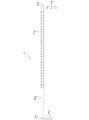
図1は、第1の実施形態に係る可搬式作業台1を示す斜視図である。なお、本願において上下等の方向は、例えば図1に示すように使用状態にある可搬式作業台1を基準とする方向をいうものとする。
本実施形態に係る可搬式作業台1では、一対の梯子状の主脚2、2間に天板3が架け渡される。各主脚2は天板3の短手辺側に回動自在に取り付けられて、天板3の裏側に折り畳み収納可能になっている(図1中の矢印R1を参照)。
Hereinafter, preferred embodiments of the present invention will be described with reference to the accompanying drawings.
(First Embodiment)
FIG. 1 is a perspective view showing a
In the
天板3の四隅には、断面矩形の管体からなる手掛かり棒4が立設される。手掛かり棒4は、主脚2に取付金具5を介して取り付けられ、水平軸まわりに回動自在に支持されて、主脚2に沿うように折り畳み収納可能になっている(図1中の矢印R2を参照)。手掛かり棒4は、作業者が主脚2を使って昇降したり、天板3上で作業したりするときに手を掛けるのに用いられる。
これら主脚2、天板3及び手掛かり棒4には、例えばアルミニウム合金が使用され、十分な強度を確保しつつ軽量化が図られている。
At the four corners of the
For example, an aluminum alloy is used for the
各手掛かり棒4に被せるようにして、断面矩形の管体からなる支柱6が設けられる。支柱6は、例えば樹脂製の管体からなり、手掛かり棒4に比べて一回りサイズの大きい断面矩形を有し、手掛かり棒4の外周面と摺動可能な内周面を有する。手掛かり棒4が主脚2に沿うように折り畳み収納されるとき、それに伴って支柱6も主脚2に沿うように折り畳み収納される。
A
本実施形態に係る可搬式作業台1では、手掛かり棒4に対する支柱6の高さ位置が可変になっている。
図2に示すように、手掛かり棒4の側面には、出入自在とされた突出部材7が配設される。図3に示すように、突出部材7は、スプリング8の弾性力により手掛かり棒4の側面から突出した状態に保たれ、スプリング8に抗して押し込むこともできる。また、図1に示すように、支柱6の高さ方向の2箇所には、突出部材7が出入可能な穴9が形成されている。
このようにした手掛かり棒4及び支柱6では、穴9に突出部材7を入れ込むことにより、支柱6の高さ位置を固定することができる。そして、突出部材7を押し込んで穴9から外せば、支柱6を手掛かり棒4に沿ってスライドさせて、手掛かり棒4に対する支柱6の高さ位置をテレスコピック式に変えることができる。本実施形態では、支柱6の高さ方向の2箇所に穴9、9が形成されており、支柱6の高さを二段階で変えることができる。
In the
As shown in FIG. 2, a protruding
In the
支柱6は、以下に詳述するように、天板3の四隅の手掛かり棒4を利用して、天板3の周縁部の上方において、天板3の長手方向に略水平に延伸する一対の長手側桟部材10、10と、天板3の短手方向に略水平に延伸する一対の短手側桟部材11、11とを支持する。
As will be described in detail below, the
天板3の長手方向に並ぶ支柱6間には、長手側桟部材10が架け渡される。なお、一対の長手側桟部材10、10は、その形状や周辺構造(支柱6への取り付け構造等)について、天板3の中心に対して点対称の関係を有する。
長手側桟部材10は、例えば樹脂製の断面矩形の管体からなり、その両端が支柱6の上部に取付金具12を介して取り付けられ、水平軸まわりに回動自在に支持される(図1中の矢印R3を参照)。また、長手側桟部材10は、その途中、好ましくは中央部で分割されている(以下、分割体10a、10bと呼ぶ)。これにより、長手側桟部材10の分割体10a、10bをそれぞれ手掛かり棒4及び支柱6に沿うように折り畳み収納可能になっている。
そして、天板3の四隅で手掛かり棒4及び支柱6を立てた状態で、分割体10a、10bを水平になるまで回動させることにより、端面同士が衝合して、長手側桟部材10を架け渡した状態とすることができる。分割体10a、10bは、例えばスライド構造の連結部材13で脱着可能に連結される。
A
The
Then, with the
長手側桟部材10には、それぞれ短手側桟部材11が取り付けられる。なお、一対の短手側桟部材11、11は、その形状や周辺構造(長手側桟部材10への取り付け構造や係止構造等)について、天板3の中心に対して点対称の関係を有する。
短手側桟部材11は、その長手方向にテレスコピック式に伸縮可能になっている。図4に示すように、短手側桟部材11は、例えばアルミニウム合金又はステンレス鋼製とされ、棒材11aがパイプ材11bに対して出入することにより伸縮可能になっている。具体的には図示しないが、棒材11aの抜けを防ぐストッパ構造を持たせるのが好ましい。
棒材11aの先端は下向きに90度に折り曲げられて、短手側桟部材11の係止突起11cとされる。また、パイプ材11bの端部には、下向きに90度に折り曲げられた略L字状の部材11dが挿設され、短手側桟部材11の基端部11eとされる。
A short
The short
The tip of the
図5に示すように、長手側桟部材10(より詳しくは分割体10a)の架け渡した状態での上面10cには、支柱6に近い位置で、短手側桟部材11の基端部11eが回動自在に支持される。
このように分割体10aの上面10cで短手側桟部材11の基端部11eが回動自在に支持されるので、短手側桟部材11を、分割体10aの上面10cに沿うように収納することができる。また、長手側桟部材10を架け渡した状態とした場合、該長手側桟部材10で支持される短手側桟部材11は垂直軸まわりに回動でき、対向位置の長手側桟部材10に向けて水平方向に回動させることができる(図5中の矢印R4を参照)。
As shown in FIG. 5, on the
In this way, the
図5に示すように、分割体10aの上面10cには係止孔14が形成されており、自身で支持する短手側桟部材11の係止突起11cを挿入して、着脱自在に係止することができる。これにより、短手側桟部材11を収納した状態で保持することができる。
また、図6に示すように、分割体10bの上面10cには係止孔15が形成されており、対向位置の長手側桟部材10で支持される短手側桟部材11の係止突起11cを挿入することができる。すなわち、短手側桟部材11を対向位置の長手側桟部材10に向けて水平方向に90度程度回動させることにより、短手側桟部材11の係止突起11cを係止孔15に挿入して、着脱自在に係止することができる。これにより、短手側桟部材11を架け渡した状態で保持することができる。
As shown in FIG. 5, a locking
Further, as shown in FIG. 6, a locking
以上のようにした可搬式作業台1を収納するときの流れをあらためて述べる。まず短手側桟部材11を、分割体10aの上面10cに沿うように収納する(図5を参照)。次に、分割体10a、10bをそれぞれ手掛かり棒4及び支柱6に沿うように折り畳み収納する(図1中の矢印R3を参照)。次に、手掛かり棒4及び支柱6を主脚2に沿うように折り畳み収納する(図1中の矢印R2を参照)。そして、主脚2を天板3の裏側に折り畳み収納することにより(図1中の矢印R1を参照)、可搬式作業台1をコンパクトに折り畳んだ収納状態とすることができる。
The flow of storing the
図6に示すように、各短手側桟部材11に、例えば面ファスナを有するベルト16を取り付けておく。短手側桟部材11を架け渡した状態で、ベルト16は短手側桟部材11から垂れ下がるかたちとなる。なお、図6以外の図では、ベルト16は省略する。
このように短手側桟部材11にベルト16を取り付けることにより、収納状態において短手側桟部材11を分割体10aに束ねて、収納状態を保持することができる。また、短手側桟部材11を分割体10aに束ねるだけでなく、さらに手掛かり棒4及び支柱6に、さらにまた主脚2に束ねられるようにしてもよい。
また、ベルト16を蛍光色等の目立つものとしておけば、昇降口となる天板3の短手辺側に短手側桟部材11が掛け渡されているか、掛け渡されていないかを一目で認識させることができる。また、天板3に立つ作業者に、短手側桟部材11の位置を視覚的に認識させることができる。この場合に、例えば支柱6や長手側桟部材10を黄色とし、それに合わせてベルト16も黄色とすれば、短手側桟部材11が金属色のままであっても、天板3に立つ作業者に対して、四方が囲まれた状態であるという感覚を与えることができる。
As shown in FIG. 6, a
By attaching the
Further, if the
ここで、天板3の長手辺及び短手辺のサイズ関係によっては、一対の長手側桟部材10、10間の距離D(図6を参照)に比べて、分割体10aの長さl(図5を参照)が短いこともありえる。この場合、短手側桟部材11の長さを一対の長手側桟部材10、10間の距離Dに合わせて定めると、短手側桟部材11を分割体10aに沿うように収納するときに、分割体10aの長さlを超えて短手側桟部材11が突出した状態となる。
そこで、短手側桟部材11をその長手方向に伸縮可能にしている。これにより、一対の長手側桟部材10、10間に架け渡すときは短手側桟部材11を伸ばし、分割体10aに沿うように収納するときには短手側桟部材11を縮めることにより、分割体10aの長さl内で短手側桟部材11を収納することができ、収納性を向上させることができる。
Here, depending on the size relationship between the longitudinal side and the lateral side of the
Therefore, the short
また、既述したように、天板3の地上高さが低い可搬式作業台1では、主脚2の長さL(図1を参照)に比べて、手掛かり棒4及び支柱6の長さの方が長くなることもありえる。この場合、手掛かり棒4及び支柱6を主脚2に沿うように折り畳み収納するときに、主脚2の長さLを超えて手掛かり棒4及び支柱6が突出した状態となる。
そこで、手掛かり棒4に対する支柱6の高さ位置を可変にしている。本実施形態では、支柱6の高さ方向の2箇所に穴9、9が形成されており、支柱6の高さを二段階で変えることができる。下側の穴9に突出部材7を入れ込んだ状態(図1に示す状態)では、支柱6の上端は天板3に立つ作業者の上半身あたりに位置し、桟部材10、11で作業者の上半身を囲むことができる。一方、上側の穴9に突出部材7を入れ込んだ状態では、支柱6の上端位置は低くなり、主脚2の長さLに比べて、手掛かり棒4及び支柱6の長さの方が短くなる。これにより、手掛かり棒4及び支柱6を主脚2に沿うように折り畳んだときに、主脚2の長さL内で手掛かり棒4及び支柱6を収納することができ、収納性を向上させることができる。
Further, as described above, in the
Therefore, the height position of the
なお、ここまで説明した構成においては、天板3の四隅で手掛かり棒4及び支柱6を立てた状態で、一対の長手側桟部材10、10を架け渡すことを前提として、一対の短手側桟部材11、11を架け渡すことができる。
本実施形態に係る可搬式作業台1では、一対の長手側桟部材10、10のうちの片方だけを架け渡した状態でも、一対の短手側桟部材11、11を架け渡すことができるようになっている。図7を参照して、一対の長手側桟部材10、10のうちの片方だけを架け渡した状態で、一対の短手側桟部材11、11を架け渡す構成を説明する。なお、図7は、本実施形態に係る可搬式作業台1とは各部のサイズ関係(天板3の長手辺及び短手辺のサイズ関係、主脚2と手掛かり棒4及び支柱6とのサイズ関係、分割体10aと短手側桟部材11とのサイズ関係等)は一致しないが、一対の短手側桟部材11、11を架け渡す構成に違いはないので、図7を参照して、同じ構成要素には同一の符号を付して説明する。
In the configuration described so far, it is assumed that the pair of
In the
以下では、一対の長手側桟部材10、10のうち、架け渡した状態の長手側桟部材を一方の長手側桟部材10Aと記し、手掛かり棒4及び支柱6に沿うように収納した状態の長手側桟部材を他方の長手側桟部材10Bと記して、詳細を説明する。
一方の長手側桟部材10Aで支持される短手側桟部材11は、既述したとおり、対向位置の他方の長手側桟部材10Bに向けて水平方向に回動させることができる。
しかしながら、他方の長手側桟部材10Bは、手掛かり棒4及び支柱6に沿うように収納されているため、係止孔15の位置が、短手側桟部材11の係止突起11cを挿入することができない位置となっている。
In the following, of the pair of
As described above, the short
However, since the other
そこで、本実施形態では、図6に示すように、分割体10bを支持する取付金具12の頂面に、短手側桟部材11の係止突起11cを挿入する係止孔17を形成している。係止孔17は、長手側桟部材10を架け渡した状態、及び長手側桟部材10を手掛かり棒4及び支柱6に沿うように収納した状態のいずれにおいても位置が不変である。これにより、短手側桟部材11を対向位置の他方の長手側桟部材10Bに向けて水平方向に90度+α程度回動させることにより、その先端部の係止突起11cを係止孔17に挿入することができる。なお、αは、係止孔15と係止孔17との位置ずれ(図6を参照)に相当する角度を意味する。
Therefore, in the present embodiment, as shown in FIG. 6, a locking
一方、他方の長手側桟部材10Bで支持される短手側桟部材11は、水平軸まわりに回動でき、対向位置の一方の長手側桟部材10Aに向けて垂直方向に回動させることができる。
この場合、短手側桟部材11の係止突起11cは、対向位置の一方の長手側桟部材10Aの上面10cに形成された係止孔15に対して90度位相がずれた位置関係となる。
そこで、本実施形態では、図4〜図6に示すように、短手側桟部材11の先端部に、係止突起11cとは90度位相をずらしたかたちで第2の係止突起11fを設けている。これにより、短手側桟部材11を対向位置の一方の長手側桟部材10Aに向けて垂直方向に回動させることにより、その先端部の第2の係止突起11fを係止孔15に挿入することができる。
On the other hand, the short
In this case, the locking
Therefore, in the present embodiment, as shown in FIGS. 4 to 6, a
このように、可搬式作業台1を、一対の長手側桟部材10、10及び一対の短手側桟部材11、11で四方を囲んだ使用状態と、一対の長手側桟部材10、10のうちの片方及び一対の短手側桟部材11、11で三方を囲んだ使用状態とに選択的に設置することができる。
通常の使用状態では、四方を囲んだ状態とすることにより、天板3に立つ作業者は、上半身がいずれかの桟部材10、11に近づいたときには天板3の周縁部に近い位置に立っていることを感知することができる。そして、天板3の長手側を壁面等に近接させる使用状態では、壁面側の長手側桟部材10を収納状態として、作業性を高めることができる。このときも、壁面側以外の三方では、天板3に立つ作業者は、上半身がいずれかの桟部材10、11に近づいたときには天板3の周縁部に近づいていることを感知することができる。
In this way, the
In the normal use state, by enclosing all four sides, the worker standing on the
(第2の実施形態)
図8は、第2の実施形態に係る可搬式作業台1を示す斜視図である。以下では、第1の実施形態との相違点を中心に説明し、第1の実施形態に係る可搬式作業台1と共通する構成要素には同一の符号を付して、その説明を省略する。
図8に示すように、第2の実施形態に係る可搬式作業台1では、天板3の長手辺の長さが第1の実施形態に比べて長くなっている。すなわち、長手側桟部材10の長さが第1の実施形態に比べて長くなっている。
この場合、長手側桟部材10の分割体10a、10bをそれぞれ手掛かり棒4及び支柱6に沿うように折り畳み収納するときに、手掛かり棒4及び支柱6の長さを超えて分割体10a、10bが突出した状態となる。
(Second Embodiment)
FIG. 8 is a perspective view showing the
As shown in FIG. 8, in the
In this case, when the divided
そこで、第2の実施形態に係る可搬式作業台では、長手側桟部材10の各分割体10a、10bが、その長手方向にテレスコピック式に伸縮可能になっている。
図9に、分割体10aの構成を示す。分割体10aは、断面矩形の第1の管体18と、断面矩形の第2の管体19とにより構成される。第1の管体18の端部には、断面矩形の管体からなる補強部材20が設けられ、この補強部材20を介して支柱6の上部の取付金具12に取り付けられる。また、第2の管体19は、第1の管体18に比べて一回りサイズの大きい断面矩形を有し、第1の管体19の外周面と摺動可能な内周面を有する。第2の管体19が第1の管体18に対してスライドすることにより伸縮可能になっている。
第1の管体18の内側面には、その長手方向に延びる長穴21が形成される。また、第2の管体19には、第1の管体18の長穴21内に配置される突起部22が設けられる。これにより、第2の管体19をまっすぐにスライドさせるようにガイドできるとともに、管体18、19のスライド範囲、すなわち分割体10aの伸縮範囲を定めることができる。
なお、分割体10bの構成も基本的には分割体10aと同様であり、ここではその説明を省略する。
Therefore, in the portable workbench according to the second embodiment, each of the divided
FIG. 9 shows the configuration of the divided
An
The configuration of the divided
以上のように、長手側桟部材10の分割体10a、10bをその長手方向に伸縮可能にしている。これにより、分割体10a、10bをそれぞれ手掛かり棒4及び支柱6に沿うように折り畳み収納するときに縮めることにより、手掛かり棒4及び支柱6の長さ内で分割体10a、10bを収納することができ、収納性を向上させることができる。
As described above, the divided
以上、本発明を実施形態と共に説明したが、上記実施形態は本発明を実施するにあたっての具体化の例を示したものに過ぎず、これらによって本発明の技術的範囲が限定的に解釈されてはならないものである。すなわち、本発明はその技術思想、又はその主要な特徴から逸脱することなく、様々な形で実施することができる。
例えば上記実施形態では、手掛かり棒4及び支柱6が主脚2に沿うように折り畳み収納可能であるとし、主脚2の長さLと手掛かり棒4及び支柱6の長さとの関係を述べたが、本発明の適用先はこれに限定されるものではない。すなわち、手掛かり棒4及び支柱6が主脚2に沿うように折り畳み収納可能であるか否かにかかわらず、また、主脚2と手掛かり棒4及び支柱6とのサイズ関係にかかわらず、本発明を適用して手掛かり棒4に対する支柱6の高さ位置を可変にするようにしてもよい。この場合でも、可搬式作業台1そのもの全高を低くすることができるので、収納性を向上させることができるといえる。
Although the present invention has been described above together with the embodiments, the above-described embodiments merely show examples of embodiment of the present invention, and the technical scope of the present invention is interpreted in a limited manner by these. It must not be. That is, the present invention can be implemented in various forms without departing from the technical idea or its main features.
For example, in the above embodiment, it is assumed that the
また、収納性に着目することに限定されるものではない。例えば桟部材10、11は天板3に立つ作業者の上半身を囲む高さ位置に配置される必要があるが、当然ながら作業者によって身長は異なる。そのため、桟部材10、11の高さによっては、身長の低い作業者にとって作業しにくくなることがある。この場合にも、手掛かり棒4に対する支柱6の高さ位置を可変にすることにより、天板3に立つ作業者の身長に合わせて桟部材10、11の高さ位置を変えることが可能になり、可搬式作業台の利便性を向上させることができる。
また、上記実施形態では、手掛かり棒4に対する支柱6の高さ位置を二段階に可変にしたが、三段階以上に可変にしてもよい。特に作業者の身長に合わせる観点からいえば、三段階以上に可変にすることにより、天板3に立つ作業者の身長に合わせて、桟部材10、11の高さ位置を細やかに変えることができる。
Moreover, it is not limited to focusing on storability. For example, the
Further, in the above embodiment, the height position of the
1:可搬式作業台、2:主脚、3:天板、4:手掛かり棒、6:支柱、10:長手側桟部材、10a:分割体、10b:分割体、11:短手側桟部材 1: Portable workbench 2: Main landing gear 3: Top plate 4: Clue bar, 6: Strut, 10: Longitudinal rail member, 10a: Split body, 10b: Split body, 11: Short side rail member
Claims (5)
前記手掛かり棒に設けられた支柱と、
前記支柱により支持され、前記天板の上方において略水平に延伸する桟部材とを備え、
前記手掛かり棒に対する前記支柱の高さ位置を可変にし、
前記桟部材として、前記天板の上方において前記天板の長手方向に延伸する一対の長手側桟部材と、前記天板の上方において前記天板の短手方向に延伸する一対の短手側桟部材とを備え、
前記短手側桟部材の一端が前記長手側桟部材に回動自在に支持されて、前記短手側桟部材が前記長手側桟部材に沿うように収納可能であり、前記短手側桟部材を対向位置の前記長手側桟部材に向けて回動させることにより、前記短手側桟部材の他端が対向位置の前記長手側桟部材に着脱自在に係止可能とされ、
前記長手側桟部材は前記支柱の上部で回動自在に支持されて、前記手掛かり棒及び前記支柱に沿うように折り畳み収納可能であり、
前記手掛かり棒及び前記支柱は、前記主脚に沿うように折り畳み収納可能であり、
前記手掛かり棒及び前記支柱を前記主脚に沿うように折り畳み収納した状態で、前記主脚の長さに比べて、前記手掛かり棒及び前記支柱の長さの方が短くなるように、前記手掛かり棒に対する前記支柱の高さ位置を変えられるようにしたことを特徴とする可搬式作業台。 A portable workbench in which a top plate is laid between a pair of main landing gears and clue rods are erected at the four corners of the top plate.
The columns provided on the clue rod and
It is provided with a crosspiece member that is supported by the support column and extends substantially horizontally above the top plate.
The height position of the support column with respect to the clue rod can be changed .
As the crosspiece members, a pair of longitudinal crosspiece members extending in the longitudinal direction of the top plate above the top plate and a pair of short side crosspieces extending in the lateral direction of the top plate above the top plate. Equipped with parts
One end of the short side rail member is rotatably supported by the long side rail member, and the short side rail member can be stored along the long side rail member, and the short side rail member can be stored. Is rotatable toward the longitudinal rail member at the opposite position so that the other end of the short side rail member can be detachably locked to the longitudinal rail member at the opposite position.
The longitudinal crosspiece member is rotatably supported by the upper part of the support column, and can be folded and stored along the clue rod and the support column.
The clue rod and the support column can be folded and stored along the main landing gear.
In a state where the clue rod and the support column are folded and stored along the main landing gear, the clue rod and the support column are shorter than the length of the main landing gear. A portable workbench characterized in that the height position of the support column can be changed.
前記各分割体をその長手方向に伸縮可能にしたことを特徴とする請求項3に記載の可搬式作業台。 The longitudinal crosspiece member is divided in the middle, and each divided body of the longitudinal crosspiece member is rotatably supported by the upper part of the support column, and can be folded and stored along the clue rod and the support column. And
The portable workbench according to claim 3 , wherein each of the divided bodies can be expanded and contracted in the longitudinal direction thereof.
Priority Applications (1)
| Application Number | Priority Date | Filing Date | Title |
|---|---|---|---|
| JP2016132582A JP6831989B2 (en) | 2016-07-04 | 2016-07-04 | Portable workbench |
Applications Claiming Priority (1)
| Application Number | Priority Date | Filing Date | Title |
|---|---|---|---|
| JP2016132582A JP6831989B2 (en) | 2016-07-04 | 2016-07-04 | Portable workbench |
Publications (2)
| Publication Number | Publication Date |
|---|---|
| JP2018003470A JP2018003470A (en) | 2018-01-11 |
| JP6831989B2 true JP6831989B2 (en) | 2021-02-24 |
Family
ID=60946019
Family Applications (1)
| Application Number | Title | Priority Date | Filing Date |
|---|---|---|---|
| JP2016132582A Active JP6831989B2 (en) | 2016-07-04 | 2016-07-04 | Portable workbench |
Country Status (1)
| Country | Link |
|---|---|
| JP (1) | JP6831989B2 (en) |
Families Citing this family (3)
| Publication number | Priority date | Publication date | Assignee | Title |
|---|---|---|---|---|
| JP7212343B2 (en) | 2018-05-21 | 2023-01-25 | ジー・オー・ピー株式会社 | Workbench |
| JP7473962B2 (en) | 2020-08-31 | 2024-04-24 | 株式会社ピカコーポレイション | Scaffolding device |
| KR102506580B1 (en) * | 2021-12-29 | 2023-03-06 | (유)은강산업 | Moving workable |
-
2016
- 2016-07-04 JP JP2016132582A patent/JP6831989B2/en active Active
Also Published As
| Publication number | Publication date |
|---|---|
| JP2018003470A (en) | 2018-01-11 |
Similar Documents
| Publication | Publication Date | Title |
|---|---|---|
| JP6831989B2 (en) | Portable workbench | |
| JP2019524164A5 (en) | ||
| US20030071177A1 (en) | Cable tray stand | |
| US7686134B1 (en) | Ladder support and bracing apparatus | |
| JP4843381B2 (en) | Portable worktable and handrail member | |
| KR200478605Y1 (en) | Foldable working platform | |
| JP7429074B2 (en) | Workbench | |
| JP2011052474A (en) | Foldable working scaffold | |
| JP5694750B2 (en) | Work platform and bridge scaffolding plate for work platform | |
| JP3180629U (en) | Stepladder platform | |
| JP6469997B2 (en) | Tent frame | |
| JP6254847B2 (en) | Stepladder platform | |
| JP5300551B2 (en) | Folding workbench | |
| JP2022103248A (en) | Work bench | |
| JP4480183B2 (en) | Folding work scaffolding | |
| JP2006342555A (en) | Portable work stand | |
| JP3117751U (en) | Telescopic aluminum stepladder | |
| JP2006052603A (en) | Expansible structure, foldable ladder, foldable support, foldable instrument, and foldable pipe | |
| JP7428425B2 (en) | Workbench | |
| JP6621249B2 (en) | Portable worktable | |
| CN208152923U (en) | A kind of construction ladder | |
| JP2003247338A (en) | Work table | |
| JP5628635B2 (en) | Work scaffolding base and cue rod holding bracket for scaffolding base | |
| JP2011169071A (en) | Workbench with handrail | |
| JP5689280B2 (en) | Workbench |
Legal Events
| Date | Code | Title | Description |
|---|---|---|---|
| A621 | Written request for application examination |
Free format text: JAPANESE INTERMEDIATE CODE: A621 Effective date: 20190614 |
|
| A977 | Report on retrieval |
Free format text: JAPANESE INTERMEDIATE CODE: A971007 Effective date: 20200527 |
|
| A131 | Notification of reasons for refusal |
Free format text: JAPANESE INTERMEDIATE CODE: A131 Effective date: 20200616 |
|
| A521 | Request for written amendment filed |
Free format text: JAPANESE INTERMEDIATE CODE: A523 Effective date: 20200805 |
|
| TRDD | Decision of grant or rejection written | ||
| A01 | Written decision to grant a patent or to grant a registration (utility model) |
Free format text: JAPANESE INTERMEDIATE CODE: A01 Effective date: 20210105 |
|
| A61 | First payment of annual fees (during grant procedure) |
Free format text: JAPANESE INTERMEDIATE CODE: A61 Effective date: 20210118 |
|
| R150 | Certificate of patent or registration of utility model |
Ref document number: 6831989 Country of ref document: JP Free format text: JAPANESE INTERMEDIATE CODE: R150 |
|
| R250 | Receipt of annual fees |
Free format text: JAPANESE INTERMEDIATE CODE: R250 |