JP6831279B2 - Melting device - Google Patents
Melting device Download PDFInfo
- Publication number
- JP6831279B2 JP6831279B2 JP2017054678A JP2017054678A JP6831279B2 JP 6831279 B2 JP6831279 B2 JP 6831279B2 JP 2017054678 A JP2017054678 A JP 2017054678A JP 2017054678 A JP2017054678 A JP 2017054678A JP 6831279 B2 JP6831279 B2 JP 6831279B2
- Authority
- JP
- Japan
- Prior art keywords
- dialysis
- timing
- predicted
- additional
- powder
- Prior art date
- Legal status (The legal status is an assumption and is not a legal conclusion. Google has not performed a legal analysis and makes no representation as to the accuracy of the status listed.)
- Active
Links
- 238000002844 melting Methods 0.000 title claims description 39
- 230000008018 melting Effects 0.000 title claims description 39
- 238000000502 dialysis Methods 0.000 claims description 209
- 239000000843 powder Substances 0.000 claims description 93
- 238000004090 dissolution Methods 0.000 claims description 86
- 239000011550 stock solution Substances 0.000 claims description 53
- 238000007792 addition Methods 0.000 claims description 51
- 239000007788 liquid Substances 0.000 claims description 50
- 239000000243 solution Substances 0.000 claims description 24
- 238000002347 injection Methods 0.000 claims description 11
- 239000007924 injection Substances 0.000 claims description 11
- XLYOFNOQVPJJNP-UHFFFAOYSA-N water Substances O XLYOFNOQVPJJNP-UHFFFAOYSA-N 0.000 description 30
- 238000010586 diagram Methods 0.000 description 14
- 239000003795 chemical substances by application Substances 0.000 description 9
- UIIMBOGNXHQVGW-UHFFFAOYSA-M Sodium bicarbonate Chemical compound [Na+].OC([O-])=O UIIMBOGNXHQVGW-UHFFFAOYSA-M 0.000 description 6
- 238000000034 method Methods 0.000 description 4
- QTBSBXVTEAMEQO-UHFFFAOYSA-N Acetic acid Chemical compound CC(O)=O QTBSBXVTEAMEQO-UHFFFAOYSA-N 0.000 description 3
- 239000008280 blood Substances 0.000 description 3
- 210000004369 blood Anatomy 0.000 description 3
- 238000001514 detection method Methods 0.000 description 3
- 229910000030 sodium bicarbonate Inorganic materials 0.000 description 3
- 235000017557 sodium bicarbonate Nutrition 0.000 description 3
- BVKZGUZCCUSVTD-UHFFFAOYSA-M Bicarbonate Chemical compound OC([O-])=O BVKZGUZCCUSVTD-UHFFFAOYSA-M 0.000 description 2
- 238000006073 displacement reaction Methods 0.000 description 2
- 238000011068 loading method Methods 0.000 description 2
- 238000002560 therapeutic procedure Methods 0.000 description 2
- DGAQECJNVWCQMB-PUAWFVPOSA-M Ilexoside XXIX Chemical compound C[C@@H]1CC[C@@]2(CC[C@@]3(C(=CC[C@H]4[C@]3(CC[C@@H]5[C@@]4(CC[C@@H](C5(C)C)OS(=O)(=O)[O-])C)C)[C@@H]2[C@]1(C)O)C)C(=O)O[C@H]6[C@@H]([C@H]([C@@H]([C@H](O6)CO)O)O)O.[Na+] DGAQECJNVWCQMB-PUAWFVPOSA-M 0.000 description 1
- 208000001647 Renal Insufficiency Diseases 0.000 description 1
- 230000003749 cleanliness Effects 0.000 description 1
- 238000007865 diluting Methods 0.000 description 1
- 239000003814 drug Substances 0.000 description 1
- 229940079593 drug Drugs 0.000 description 1
- 230000000694 effects Effects 0.000 description 1
- 230000003203 everyday effect Effects 0.000 description 1
- 201000006370 kidney failure Diseases 0.000 description 1
- 239000004973 liquid crystal related substance Substances 0.000 description 1
- 230000002934 lysing effect Effects 0.000 description 1
- 238000002156 mixing Methods 0.000 description 1
- 238000002360 preparation method Methods 0.000 description 1
- 238000000746 purification Methods 0.000 description 1
- 229910052708 sodium Inorganic materials 0.000 description 1
- 239000011734 sodium Substances 0.000 description 1
- 239000008400 supply water Substances 0.000 description 1
- 238000005303 weighing Methods 0.000 description 1
Images


Classifications
-
- B—PERFORMING OPERATIONS; TRANSPORTING
- B01—PHYSICAL OR CHEMICAL PROCESSES OR APPARATUS IN GENERAL
- B01F—MIXING, e.g. DISSOLVING, EMULSIFYING OR DISPERSING
- B01F21/00—Dissolving
-
- A—HUMAN NECESSITIES
- A61—MEDICAL OR VETERINARY SCIENCE; HYGIENE
- A61M—DEVICES FOR INTRODUCING MEDIA INTO, OR ONTO, THE BODY; DEVICES FOR TRANSDUCING BODY MEDIA OR FOR TAKING MEDIA FROM THE BODY; DEVICES FOR PRODUCING OR ENDING SLEEP OR STUPOR
- A61M1/00—Suction or pumping devices for medical purposes; Devices for carrying-off, for treatment of, or for carrying-over, body-liquids; Drainage systems
- A61M1/14—Dialysis systems; Artificial kidneys; Blood oxygenators ; Reciprocating systems for treatment of body fluids, e.g. single needle systems for hemofiltration or pheresis
- A61M1/16—Dialysis systems; Artificial kidneys; Blood oxygenators ; Reciprocating systems for treatment of body fluids, e.g. single needle systems for hemofiltration or pheresis with membranes
- A61M1/1654—Dialysates therefor
- A61M1/1656—Apparatus for preparing dialysates
- A61M1/1666—Apparatus for preparing dialysates by dissolving solids
-
- B—PERFORMING OPERATIONS; TRANSPORTING
- B01—PHYSICAL OR CHEMICAL PROCESSES OR APPARATUS IN GENERAL
- B01F—MIXING, e.g. DISSOLVING, EMULSIFYING OR DISPERSING
- B01F21/00—Dissolving
- B01F21/30—Workflow diagrams or layout of plants, e.g. flow charts; Details of workflow diagrams or layout of plants, e.g. controlling means
Landscapes
- Health & Medical Sciences (AREA)
- Heart & Thoracic Surgery (AREA)
- Chemical Kinetics & Catalysis (AREA)
- Urology & Nephrology (AREA)
- Chemical & Material Sciences (AREA)
- Anesthesiology (AREA)
- Vascular Medicine (AREA)
- Engineering & Computer Science (AREA)
- Emergency Medicine (AREA)
- Biomedical Technology (AREA)
- Hematology (AREA)
- Life Sciences & Earth Sciences (AREA)
- Animal Behavior & Ethology (AREA)
- General Health & Medical Sciences (AREA)
- Public Health (AREA)
- Veterinary Medicine (AREA)
- External Artificial Organs (AREA)
Description
本発明は、透析用粉末剤を溶解して透析用原液を得るための溶解装置に関するものである。 The present invention relates to a dissolution device for dissolving a dialysis powder to obtain a dialysis stock solution.
病院等で腎不全患者の治療に使用される透析液は、一般に重炭酸塩系と酢酸系とに区分され、このうち重炭酸塩系の透析液は、重炭酸ナトリウムを含まないもの(以下、A剤という。)と重炭酸ナトリウム(以下、B剤という。)の2種類の剤に水を混合して調整されるものである。近年、運搬性向上の観点から、これらA剤及びB剤を粉末化したもの(以下、「透析用粉末剤」という。)を透析治療直前や透析治療中に溶解する試みがなされている。 The dialysate used for the treatment of patients with renal failure in hospitals is generally classified into bicarbonate type and acetic acid type, and among them, the bicarbonate type dialysate does not contain sodium bicarbonate (hereinafter, It is prepared by mixing water with two types of agents, agent A) and sodium bicarbonate (hereinafter referred to as agent B). In recent years, from the viewpoint of improving transportability, attempts have been made to dissolve these powders A and B (hereinafter referred to as "dialysis powder") immediately before dialysis treatment or during dialysis treatment.
すなわち、透析用粉末剤を溶解して作製される原液(A剤を溶解したA原液やB剤を溶解したB原液)は、清浄性の観点から溶解後にできるだけ早く治療に使用することが好ましく、特にB原液は、経時的に成分が変化する虞があるため、作り置きして長時間放置しておくことは好ましくないことから、透析治療直前にA原液やB原液を作製する必要があり、さらに、透析治療中においてA原液やB原液が不足した場合、それぞれの原液を追加で作製する必要がある。 That is, the undiluted solution prepared by dissolving the dialysis powder (the A undiluted solution in which the A agent is dissolved or the B undiluted solution in which the B agent is dissolved) is preferably used for treatment as soon as possible after the dissolution from the viewpoint of cleanliness. In particular, since the components of the B stock solution may change over time, it is not preferable to leave the B stock solution for a long time. Therefore, it is necessary to prepare the A stock solution and the B stock solution immediately before the dialysis treatment. Furthermore, if the A stock solution or the B stock solution is insufficient during dialysis treatment, it is necessary to additionally prepare each stock solution.
このように、透析治療毎に溶解作業が必要となることから、従来から溶解のための溶解装置が各種提案されている。例えば特許文献1〜3には、2つの溶解槽を併設した溶解装置が開示されており、かかる構成により、透析治療中において、一方の溶解槽から透析液原液を透析装置側に送液している間に、他方の溶解槽に透析用粉末剤を投入させて透析用粉末剤の追加溶解を行うことができる。
As described above, since a dissolution operation is required for each dialysis treatment, various dissolution devices for dissolution have been conventionally proposed. For example,
しかしながら、上記従来技術においては、溶解槽内に収容された透析用粉末剤が所定の液位を下回った際、これを液位センサ等にて検出して医療従事者等の作業者に対して報知することにより、透析用粉末剤を追加で投入させ得る構成とされているものの、追加の透析用粉末剤の投入タイミングを予め把握させることができない構成であった。よって、作業者が他の作業を行っている最中であっても優先して透析用粉末剤の追加投入を行う必要があり、早急に対応できない場合、透析用原液が不足してしまう虞があった。 However, in the above-mentioned prior art, when the dialysis powder contained in the dissolution tank falls below a predetermined liquid level, this is detected by a liquid level sensor or the like for workers such as medical staff. Although the configuration is such that the additional dialysis powder can be added by notifying the notification, the timing of adding the additional dialysis powder cannot be grasped in advance. Therefore, it is necessary to prioritize the addition of dialysis powder even while the worker is performing other work, and if it cannot be dealt with immediately, there is a risk that the dialysis stock solution will run short. there were.
本発明は、このような事情に鑑みてなされたもので、追加の透析用粉末剤の投入タイミングを作業者に対して予め把握させることができる溶解装置を提供することにある。 The present invention has been made in view of such circumstances, and an object of the present invention is to provide a dissolving device capable of allowing an operator to grasp in advance the timing of adding an additional dialysis powder.
請求項1記載の発明は、透析用粉末剤を溶解して透析用原液を得るとともに、その溶解された透析用原液を所定量収容し得る溶解槽を具備し、透析治療中、患者に透析治療を施すための複数の透析装置側に前記溶解槽の透析用原液を送液するのに伴って、追加の透析用粉末剤を所定量毎に投入させて溶解し得る溶解装置において、過去の透析治療中における追加の透析用粉末剤を投入したタイミングを実績投入タイミングとして記憶する記憶手段と、前記記憶手段で記憶された実績投入タイミングに基づいて、これから行われる透析治療中における追加の透析用粉末剤を投入するタイミングを予測投入タイミングとして予測する予測手段と、前記予測手段で予測されたタイミングであって透析治療中における追加の透析用粉末剤を投入するタイミングである前記予測投入タイミングを表示する表示手段とを具備したことを特徴とする。
The invention according to
請求項2記載の発明は、請求項1記載の溶解装置において、透析治療において必要とされる透析用粉末剤の総量を入力し得るとともに、入力された透析用粉末剤の総量に基づいて、透析用粉末剤を追加投入すべき追加回数と、各追加投入タイミングで投入すべき透析用粉末剤の追加量とを設定し得る設定手段を具備し、前記表示手段は、前記予測投入タイミングと併せて前記設定手段で設定された追加回数及び追加量を表示可能とされたことを特徴とする。
In the invention according to
請求項3記載の発明は、請求項2記載の溶解装置において、前記設定手段で設定された追加回数又は追加量を任意に変更可能とされるとともに、前記予測手段は、当該変更に対応して前記予測投入タイミングを修正し、その修正された予測投入タイミングを前記表示手段にて表示させ得ることを特徴とする。
The invention according to
請求項4記載の発明は、請求項2又は3記載の溶解装置において、前記溶解槽内に収容された透析用原液の液位を連続的且つリアルタイムに検出可能な液位検出手段と、前記液位検出手段で検出された透析用原液の液位に基づいて前記透析用粉末剤の追加投入タイミングを報知し得る報知手段とを具備するとともに、前記予測手段は、前記報知手段で報知された追加投入タイミングに基づいて次回以降の前記予測投入タイミングを修正し、その修正された予測投入タイミングを前記表示手段にて表示させ得ることを特徴とする。
The invention according to
請求項5記載の発明は、請求項1〜4の何れか1つに記載の溶解装置において、前記記憶手段は、医療施設における患者の治療日程に対応した特定の治療日毎に前記実績投入タイミングを記憶するとともに、前記予測手段は、当該特定の治療日毎の予測投入タイミングを予測して前記表示手段で表示させ得ることを特徴とする。
The invention according to
請求項6記載の発明は、請求項1〜5の何れか1つに記載の溶解装置において、前記表示手段で表示される予測投入タイミングは、時刻又は溶解開始時からの経過時間とされることを特徴とする。
According to the invention of
請求項1の発明によれば、過去の透析治療中における追加の透析用粉末剤を投入したタイミングを実績投入タイミングとして記憶する記憶手段と、記憶手段で記憶された実績投入タイミングに基づいて、これから行われる透析治療中における追加の透析用粉末剤を投入するタイミングを予測投入タイミングとして予測する予測手段と、予測手段で予測されたタイミングであって透析治療中における追加の透析用粉末剤を投入するタイミングである予測投入タイミングを表示する表示手段とを具備したので、追加の透析用粉末剤の投入タイミングを作業者に対して予め把握させることができる。
According to the invention of
請求項2の発明によれば、透析治療において必要とされる透析用粉末剤の総量を入力し得るとともに、入力された透析用粉末剤の総量に基づいて、透析用粉末剤を追加投入すべき追加回数と、各追加投入タイミングで投入すべき透析用粉末剤の追加量とを設定し得る設定手段を具備し、表示手段は、予測投入タイミングと併せて設定手段で設定された追加回数及び追加量を表示可能とされたので、追加回数及び追加量と併せて追加の透析用粉末剤の投入タイミングを作業者に対して予め把握させることができる。
According to the invention of
請求項3の発明によれば、設定手段で設定された追加回数又は追加量を任意に変更可能とされるとともに、予測手段は、当該変更に対応して予測投入タイミングを修正し、その修正された予測投入タイミングを表示手段にて表示させ得るので、追加回数又は追加量の変更に伴う予測投入タイミングのずれを自動的に修正して表示させることができる。
According to the invention of
請求項4の発明によれば、溶解槽内に収容された透析用原液の液位を連続的且つリアルタイムに検出可能な液位検出手段と、液位検出手段で検出された透析用原液の液位に基づいて透析用粉末剤の追加投入タイミングを報知し得る報知手段とを具備するとともに、予測手段は、報知手段で報知された追加投入タイミングに基づいて次回以降の予測投入タイミングを修正し、その修正された予測投入タイミングを表示手段にて表示させ得るので、予測投入タイミングが報知手段で報知された実際の追加投入タイミングに対してずれた場合、そのずれを修正して表示させることができ、予測投入タイミングを精度よく予測することができる。
According to the invention of
請求項5の発明によれば、記憶手段は、医療施設における患者の治療日程に対応した特定の治療日毎に実績投入タイミングを記憶するとともに、予測手段は、当該特定の治療日毎の予測投入タイミングを予測して表示手段で表示させ得るので、患者の治療日程が予め決まっている透析治療において、予測投入タイミングをより精度よく予測することができる。
According to the invention of
請求項6の発明によれば、表示手段で表示される予測投入タイミングは、時刻又は溶解開始時からの経過時間とされるので、追加の透析用粉末剤の投入タイミングを作業者に対してより正確に把握させることができる。
According to the invention of
以下、本発明の実施形態について図面を参照しながら具体的に説明する。
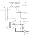
本実施形態に係る溶解装置は、透析用粉末剤を溶解し透析用原液を得るものであって、図1〜5に示すように、透析用粉末剤を溶解して透析用原液を得るとともに、その溶解された透析用原液を所定量収容し得る第1溶解槽2及び第2溶解槽3と、入力手段4と、記憶手段5と、設定手段6と、予測手段7と、表示手段8と、液位検出手段9と、報知手段10とを有して構成されている。
Hereinafter, embodiments of the present invention will be specifically described with reference to the drawings.
The dissolving apparatus according to the present embodiment dissolves a dialysis powder to obtain a dialysis stock solution, and as shown in FIGS. 1 to 5, the dialysis powder is dissolved to obtain a dialysis stock solution, and the dialysis stock solution is obtained. A
第1溶解槽2は、重炭酸ナトリウムを含まないもの(A剤)又は重炭酸ナトリウム(B剤)の2種類のうち何れかから成る透析用粉末剤を投入可能な収容空間を有するとともに、給水源から延設された給水ラインL1が接続されている。かかる給水ラインL1には、図5に示すように、電磁弁等から成るバルブV1が配設されており、このバルブV1を開状態とすることにより第1溶解槽2内に給水可能とされている。しかして、給水源から所定量の水を第1溶解槽2内に供給して収容させた後、その水の量に対して決められた量(規定量)の透析用粉末剤を第1溶解槽2に投入することにより、所定量及び所定濃度の透析用原液を得ることができる。
The
第2溶解槽3は、第1溶解槽2に投入される透析用粉末剤と同種の透析用粉末剤を投入可能な空間を有するとともに、図5に示すように、当該第2溶解槽3と第1溶解槽2とを連結する接続ラインL4が接続されている。かかる接続ラインL4には、電磁弁等からなるバルブV2、V3、V4が配設されており、これらバルブV2、V3、V4を開状態にすることにより、第1溶解槽2内の液体を第2溶解槽3内に移送可能とされている。なお、本実施形態に係る第2溶解槽3は、第1溶解槽2に比べて相対的に容量が小さなタンクとされ、オーバーフローラインL5にて第1溶解槽2に接続されている。
The
また、第1溶解槽2は、給水ラインL1及び接続ラインL4の他、接続ラインL2が接続されている。かかる接続ラインL2は、一端が第1溶解槽2に接続されるとともに、他端が接続ラインL4における接続部b(バルブV2とバルブV3との間の位置)に接続されている。さらに、接続ラインL2における接続部a(ポンプP1の配設部位と接続部bとの間の位置)には、送液ラインL3の基端が接続されている。かかる送液ラインL3は、ポンプP2が配設されるとともに、電磁弁等から成るバルブV5が配設されている。なお、送液ラインL3と接続ラインL4との間には、電磁弁等から成るバルブV6が配設された接続ラインL6が接続されている。
Further, in the
送液ラインL3は、その途中にポンプP2が配設されるとともに、先端が透析液供給装置B(図4参照)に接続されており、溶解装置1で作製された透析用原液を透析液供給装置Bに送液可能とされている。かかる透析液供給装置Bは、溶解装置1から送液された透析用原液を所定濃度に希釈して透析液を作製するもので、図4に示すように、配管を介して複数の透析装置Aに接続されている。しかして、溶解装置1で作製された透析用原液は、透析液供給装置Bで所定濃度の透析液とされ、各透析装置Aに送液されて透析治療が施されるようになっている。
In the liquid feeding line L3, a pump P2 is arranged in the middle thereof, and the tip thereof is connected to a dialysate supply device B (see FIG. 4), and a dialysate undiluted solution prepared by the
液位検出手段9は、第1溶解槽2に配設されたセンサから成るもので、第1溶解槽2内に収容された透析用原液の液位を連続的且つリアルタイムに検出可能なものである。本実施形態に係る液位検出手段9は、第1溶解槽2内に収容された液体の液面に浮いて上下移動可能な浮き手段を有した磁歪式リニア変位センサで構成されており、浮き手段の位置を連続的且つリアルタイムに検出することにより、液面(すなわち液位)を検知可能とされている。
The liquid
なお、液位検出手段9は、第1溶解槽2内に収容された透析用原液(供給された水又は溶液であってもよい)の液位を連続的且つリアルタイムに検出可能なものであれば、接触式又は非接触式のどちらのタイプでもよく、本実施形態の如く浮き手段による磁歪式リニア変位センサの他、超音波センサ等により構成するようにしてもよい。また、本実施形態においては、液位検出手段9が第1溶解槽2のみに配設されているが、当該第1溶解槽2と共に第2溶解槽3にも配設するようにしてもよい。
The liquid
さらに、液位検出手段9は、報知手段10と電気的に接続されている。かかる報知手段10は、液位検出手段9で検出された透析用原液の液位に基づいて透析用粉末剤の追加投入タイミングを報知し得るもので、音声や効果音等を出力させるスピーカや警告灯などから構成されている。すなわち、液位検出手段9にて検出された液位が所定の高さより低く、透析用原液が不足すると予測される時点において、報知手段10にて報知することにより、追加の透析用粉末剤を医療従事者等の作業者に投入させ、追加溶解することにより透析用原液を追加で作製することができるのである。
Further, the liquid
次に、本実施形態に係る溶解装置1による溶解のための動作について説明する。
先ず、透析治療前(治療前日の夜等)において、図6に示すように、第2溶解槽3に所定量(準備溶解袋数)の透析用粉末剤を投入して収容させておく。そして、バルブV1、V2を開状態としつつバルブV3〜V6を閉状態とすることにより、給水源から第1溶解槽2に給水するとともに、ポンプP1を駆動させることにより、供給された水を循環させる。
Next, the operation for melting by the
First, before the dialysis treatment (the night before the treatment, etc.), as shown in FIG. 6, a predetermined amount (the number of prepared dissolution bags) of the dialysis powder is charged into the
その後、図7に示すように、バルブV1、V3、V4を開状態としつつバルブV2、V5、V6を閉状態とし、給水源からの給水及びポンプP1の駆動を継続して行わせることにより、第1溶解槽2内の水を第2溶解槽3に送り込む。これにより、予め第2溶解槽3内に収容された透析用粉末剤に水が送り込まれて溶解するとともに、その溶解液(透析用原液となる過程の溶液)がオーバーフローラインL5を介して第1溶解槽2に送り込まれることとなる。
After that, as shown in FIG. 7, the valves V1, V3, and V4 are opened and the valves V2, V5, and V6 are closed, and the water supply from the water supply source and the driving of the pump P1 are continuously performed. The water in the
そして、所定量の給水が行われると、図8に示すように、バルブV3、V4を開状態としつつバルブV1、V2、V5、V6を閉状態とし、給水源からの給水を停止する一方、ポンプP1の駆動を継続して行わせることにより、第1溶解槽2と第2溶解槽3との間で透析用原液を循環させる。これにより、作製した透析用原液を攪拌することができ、均一な濃度の透析用原液を得ることができる。
Then, when a predetermined amount of water is supplied, as shown in FIG. 8, the valves V3 and V4 are opened and the valves V1, V2, V5 and V6 are closed, and the water supply from the water supply source is stopped. By continuously driving the pump P1, the stock solution for dialysis is circulated between the
上記のように第1溶解槽2及び第2溶解槽3のそれぞれに透析用原液が収容された状態において、図9に示すように、バルブV5を開状態としつつバルブV1〜V4、V6を閉状態とし、ポンプP1及びポンプP2を駆動させることにより、送液ラインL3を介して第1溶解槽2内の透析用原液を透析液供給装置Bに送液することができ、所定濃度の透析液を各透析装置Aに供給させて透析治療を行わせることができる。
As described above, in the state where the stock solution for dialysis is contained in each of the
その後、液位検出手段9にて第1溶解槽2内の透析用原液の液位が所定高さに達すると、報知手段10にて追加投入のための報知がなされる。この場合、図10に示すように、バルブV1、V2、V4、V6を開状態としつつバルブV3、V5を閉状態とし、給水源からの給水を行わせる一方、ポンプP2の駆動を継続して行わせることにより、第1溶解槽2に代えて第2溶解槽3内の透析用原液を透析液供給装置Bに送液する。
After that, when the liquid level of the stock solution for dialysis in the
しかして、第1溶解槽2内に所定量(追加投入袋数)の追加の透析用粉末剤を投入させることができ、その投入された透析用粉末剤が給水源からの給水によって溶解されることとなる。なお、ポンプP1を駆動させることにより、透析用原液となる過程の溶液を循環させることができる。これにより、第1溶解槽2に代えて第2溶解槽3からの透析用原液の送液が引き続き行われるとともに、第1溶解槽2において追加の透析用粉末剤を投入させて溶解することができる。
Therefore, a predetermined amount (the number of additional charging bags) of the additional dialysis powder can be charged into the
そして、所定量の給水が行われると、図11に示すように、バルブV2、V4、V6を開状態としつつバルブV1、V3、V5を閉状態とし、給水源からの給水を停止する一方、ポンプP1、P2の駆動を継続して行わせることにより、第2溶解槽3から透析用原液の送液を引き続き行わせるとともに、第1溶解槽2内の透析用原液を循環させて攪拌し、均一な濃度の透析用原液を得ることができる。
Then, when a predetermined amount of water is supplied, as shown in FIG. 11, the valves V2, V4, and V6 are opened and the valves V1, V3, and V5 are closed, and the water supply from the water supply source is stopped. By continuously driving the pumps P1 and P2, the undiluted solution for dialysis is continuously sent from the
上記のように第1溶解槽2に透析用原液が収容された状態において、図12に示すように、バルブV2〜V5を開状態としつつバルブV1、V6を閉状態とし、ポンプP1及びポンプP2を駆動させることにより、送液ラインL3を介して第1溶解槽2内の透析用原液を透析液供給装置Bに送液することができ、所定濃度の透析液を各透析装置Aに供給させて透析治療を行わせることができる。このとき、第1溶解槽2内の透析用原液の一部は、第2溶解槽3内に移送され、オーバーフローラインL5にてオーバーフローする状態まで透析用原液が送り込まれることとなる。
In the state where the undiluted solution for dialysis is contained in the
その後、図9に示すように、バルブV5を開状態としつつバルブV1〜V4、V6を閉状態とし、ポンプP1及びポンプP2を駆動させることにより、送液ラインL3を介して第1溶解槽2内の透析用原液を透析液供給装置Bに送液することができ、所定濃度の透析液を各透析装置Aに供給させて透析治療を行わせることができる。これにより、第1溶解槽2にて追加溶解された透析用原液を透析液供給装置Bに供給することができるので、各透析装置Aによる透析治療を継続して行わせることができる。
After that, as shown in FIG. 9, the valves V1 to V4 and V6 are closed while the valves V5 are open, and the pumps P1 and P2 are driven to drive the
このように、本実施形態に係る溶解装置1は、透析治療中、患者に透析治療を施すための複数の透析装置A側に第1溶解槽2及び第2溶解槽3の透析用原液を送液するのに伴って、追加の透析用粉末剤を所定量毎(本実施形態においては透析用粉末剤を収容する袋単位(袋数))に投入させて溶解し得るものであり、所謂バッチ式と称される溶解装置から成るものとされている。
As described above, the dissolving
ここで、本実施形態に係る溶解装置1の筐体部には、図5に示すように、入力手段4と、記憶手段5と、設定手段6と、予測手段7と、表示手段8とを有して構成されている。入力手段4は、操作者が入力操作可能な操作スイッチやタッチパネル等により構成されたもので、本実施形態においては、透析治療において必要とされる透析用粉末剤の総量を入力し得るものとされている。
Here, as shown in FIG. 5, the housing portion of the
表示手段8は、溶解作業に関する種々表示を行い得る液晶モニタ等にて構成されるもので、本実施形態においては、入力手段4と表示手段8とを兼用するタッチパネルにて構成されている。なお、入力手段4と表示手段8とを兼用するタッチパネルとするものの他、入力手段4と表示手段8とを別個に具備するものとしてもよい。 The display means 8 is composed of a liquid crystal monitor or the like capable of performing various displays related to the melting operation, and in the present embodiment, the display means 8 is composed of a touch panel that also serves as the input means 4 and the display means 8. In addition to the touch panel that also serves as the input means 4 and the display means 8, the input means 4 and the display means 8 may be separately provided.
記憶手段5は、過去の透析治療中における追加の透析用粉末剤を投入したタイミングを実績投入タイミングとして記憶し得るもので、本実施形態においては、病院等の医療施設における患者の治療日程に対応した特定の治療日毎(具体的には曜日毎)に実績投入タイミングを記憶するよう構成されている。すなわち、透析患者は、通常、決まった曜日(例えば月曜日、水曜日及び金曜日)に透析治療を受けることから、医療従事者も曜日毎に決まった作業を行うこととなる。したがって、曜日(患者の治療日程に対応した特定の治療日毎)によって透析用原液や透析液の消費量及び流量がほぼ一定となるので、曜日毎に実績投入タイミングを記憶すれば追加の透析用粉末剤を投入するタイミングを精度よく予測することができる。 The storage means 5 can store the timing of adding the additional dialysis powder during the past dialysis treatment as the actual input timing, and in the present embodiment, it corresponds to the treatment schedule of the patient in a medical facility such as a hospital. It is configured to store the actual input timing for each specific treatment day (specifically, for each day). That is, since dialysis patients usually receive dialysis treatment on fixed days of the week (for example, Monday, Wednesday, and Friday), medical staff also perform fixed work on each day of the week. Therefore, the consumption amount and flow rate of the dialysis stock solution and dialysate are almost constant depending on the day of the week (each specific treatment day corresponding to the patient's treatment schedule). Therefore, if the actual input timing is memorized for each day of the week, additional dialysis powder is added. It is possible to accurately predict the timing of adding the agent.
設定手段6は、入力手段4にて入力された透析用粉末剤の総量に基づいて、透析用粉末剤を追加投入すべき追加回数と、各追加投入タイミングで投入すべき透析用粉末剤の追加量とを自動的に設定し得るものである。例えば、表示手段8において、図13に示すようなメニュー画面で特定の曜日(例えば月曜日)を選択し、その日に必要とされる透析用粉末剤の総量を入力すると、準備溶解量(治療前に予め溶解する袋数)と、透析用粉末剤を追加する回数(追加回数)と、各追加タイミングで投入すべき透析用粉末剤の投入量(追加時の袋数)とを自動的に割り振って設定し、図14に示すように、表示手段8にて表示させるよう構成されている。 The setting means 6 adds the number of additional dialysis powders to be added and the addition of the dialysis powders to be added at each additional addition timing based on the total amount of the dialysis powders input by the input means 4. The amount and can be set automatically. For example, in the display means 8, when a specific day of the week (for example, Monday) is selected on the menu screen as shown in FIG. 13 and the total amount of dialysis powder required for that day is input, the prepared dissolution amount (before treatment) is input. The number of bags to be dissolved in advance), the number of times the dialysis powder is added (the number of additions), and the amount of the dialysis powder to be added at each additional timing (the number of bags at the time of addition) are automatically assigned. It is configured to be set and displayed by the display means 8 as shown in FIG.
予測手段7は、記憶手段5で記憶された実績投入タイミング(本実施形態においては時刻)に基づいて、これから行われる透析治療中における追加の透析用粉末剤を投入するタイミングを予測投入タイミングとして予測し得るものである。具体的には、記憶手段5で記憶された実績投入タイミングのうち直近のもの(これから透析治療する日が月曜日であれば、先週の月曜日のもの)が予測投入タイミングとされるとともに、その後の曜日毎の透析治療日において、実績投入タイミングを順次上書き保存し、記憶手段5で記憶される実績投入タイミングを透析治療日毎にアップデート(記憶した情報を更新)するようになっている。 The prediction means 7 predicts the timing of adding the additional dialysis powder during the dialysis treatment to be performed as the predicted input timing based on the actual input timing (time in the present embodiment) stored in the storage means 5. It is possible. Specifically, among the actual input timings stored in the storage means 5, the latest input timing (if the day of dialysis treatment is from now on is Monday, the one of last Monday) is set as the predicted input timing, and the day after that. On each dialysis treatment day, the actual input timing is sequentially overwritten and saved, and the actual input timing stored in the storage means 5 is updated (stored information is updated) for each dialysis treatment day.
また、予測手段7による予測投入タイミングの予測方法として、上記のものに限らず、例えば過去の透析治療中における複数の実績投入タイミングを記憶手段5で記憶しておき、その平均値等を演算して予測投入タイミングとするもの、或いは曜日毎の透析用原液の消費パターン(消費傾向)が一定となったことを条件として、その消費パターンに基づいて予測投入タイミングを予測するもの等であってもよい。 Further, the method of predicting the predicted input timing by the predicting means 7 is not limited to the above, for example, a plurality of actual input timings during the past dialysis treatment are stored in the storage means 5, and the average value or the like is calculated. Even if the predicted loading timing is used, or if the consumption pattern (consumption tendency) of the undiluted solution for dialysis is constant for each day, the predicted loading timing is predicted based on the consumption pattern. Good.
なお、最初に本装置を使用する場合や試運転を行う場合等、記憶手段5にて実績投入タイミングが記憶されていない場合、例えば1クール(特定の医療施設において1日で行われる治療の単位)を5時間とし、そのうち準備作業に30分、返血作業に30分及び液置換に30分それぞれかかることを想定し、クール毎の血液治療の開始時刻及び患者の数(床数)等を考慮すれば、実績投入タイミングが記憶されていなくても透析用粉末剤の投入タイミングを予測することができる。 If the storage means 5 does not store the actual input timing, such as when using this device for the first time or when performing a trial run, for example, one course (a unit of treatment performed in one day at a specific medical facility). It is assumed that it will take 30 minutes for preparation work, 30 minutes for blood return work, and 30 minutes for liquid replacement, and consider the start time of blood treatment and the number of patients (number of beds) for each course. By doing so, it is possible to predict the injection timing of the dialysis powder even if the actual injection timing is not stored.
また、溶解工程において、その日の透析用粉末剤の総量(袋数)が一時的に増加する場合、袋数1つにつき患者が1人変更になったと想定し、それまでの実績データに透析用原液の消費速度を対応させて透析用原液の消費傾向を作成し、透析用粉末剤の投入タイミングを予測してもよく、透析用粉末剤の総量(袋数)が恒久的に増加する場合、袋数1つにつき患者が1人変更になったと想定し、透析用原液の消費速度を対応させて透析用原液の消費傾向を作成し、透析用粉末剤の投入タイミングを予測してもよい。 In addition, if the total amount (number of bags) of dialysis powder on that day increases temporarily in the dissolution process, it is assumed that one patient has changed for each number of bags, and the actual data up to that point is for dialysis. The consumption tendency of the dialysis stock solution may be created by matching the consumption rate of the stock solution to predict the injection timing of the dialysis powder, and when the total amount (number of bags) of the dialysis powder increases permanently. Assuming that one patient is changed for each number of bags, the consumption tendency of the dialysis stock solution may be created by matching the consumption rate of the dialysis stock solution, and the timing of adding the dialysis powder may be predicted.
表示手段8は、上述の如く溶解作業に関する種々表示を行い得るもので、特に本実施形態においては、図14に示すように、予測手段7で予測された予測投入タイミングを表示し得るよう構成されている。また、本実施形態に係る表示手段8は、同図に示すように、予測手段7で予測された予測投入タイミングと併せて設定手段6で設定された追加回数及び追加量が表示されている。しかるに、本実施形態においては、表示手段8で表示される予測投入タイミングが「時刻」とされているが、投入タイミングが分かる他の形態であってもよく、例えば溶解開始時からの経過時間を予測投入タイミングとして表示するようにしてもよい。
As described above, the display means 8 can display various indications related to the melting operation, and particularly in the present embodiment, as shown in FIG. 14, the display means 8 is configured to be able to display the predicted input timing predicted by the
さらに、本実施形態に係る予測手段7は、報知手段10で報知された追加投入タイミングに基づいて次回以降の予測投入タイミングを修正し、その修正された予測投入タイミングを表示手段8にて表示させ得るよう構成されている。例えば、図17に示すように、報知手段10で報知された実際の追加投入タイミングと、そのときの予測手段7で予測された予測投入タイミングとの時間差(Δt)を算出し(S1)、次回以降の予測投入タイミングを時間差(Δt)だけずらす(S2)ことにより、予測投入タイミングを逐次修正し、その修正された予測投入タイミングが表示手段8にて表示されることとなる。 Further, the prediction means 7 according to the present embodiment corrects the predicted input timing from the next time onward based on the additional input timing notified by the notification means 10, and causes the display means 8 to display the corrected predicted input timing. It is configured to get. For example, as shown in FIG. 17, the time difference (Δt) between the actual additional input timing notified by the notification means 10 and the predicted input timing predicted by the prediction means 7 at that time is calculated (S1), and the next time. By shifting the subsequent predicted input timing by the time difference (Δt) (S2), the predicted input timing is sequentially corrected, and the corrected predicted input timing is displayed on the display means 8.
またさらに、本実施形態においては、設定手段6で設定された追加回数又は追加量を任意に変更可能とされるとともに、予測手段7は、当該変更に対応して予測投入タイミングを修正し、その修正された予測投入タイミングを表示手段8にて表示させ得るよう構成されている。例えば、図15に示すように、1回目における透析用粉末剤の追加量を10袋から8袋に変更した場合、その分、最終回(同図においては4回目)における追加量を修正して表示するとともに、2回目以降の予測投入タイミングをずらして表示させる。また、図16に示すように、1回あたりの透析液粉末剤の追加量を8袋に減らし、追加回数を5回に増加させることも可能とされている。 Furthermore, in the present embodiment, the number of additions or the amount of addition set by the setting means 6 can be arbitrarily changed, and the prediction means 7 modifies the prediction input timing in response to the change. The display means 8 can display the corrected predicted input timing. For example, as shown in FIG. 15, when the additional amount of the dialysis powder in the first round is changed from 10 bags to 8 bags, the additional amount in the final round (the fourth round in the figure) is corrected accordingly. In addition to displaying, the predicted input timing for the second and subsequent times is shifted and displayed. Further, as shown in FIG. 16, it is also possible to reduce the amount of dialysate powder added at one time to 8 bags and increase the number of times of addition to 5 times.
このように、追加量(袋数)を変更する場合、図19に示すように、記憶手段5にて過去の透析治療における透析用原液の経時的な消費傾向を記憶しておく。そして、例えば図18に示すように、変更される袋数から生成される透析用原液の量を算出し(S1)、その透析用原液が消費される時刻を記憶手段5に記憶されたデータ(透析用原液の経時的な消費傾向)から予測(S2)した後、袋数が変更された以降の予測投入タイミングを修正(S3)することにより、その修正された予測投入タイミングが表示手段8にて表示されることとなる。 When the additional amount (number of bags) is changed in this way, as shown in FIG. 19, the storage means 5 stores the tendency of consumption of the dialysis stock solution over time in the past dialysis treatment. Then, for example, as shown in FIG. 18, the amount of the dialysis stock solution generated from the changed number of bags is calculated (S1), and the time when the dialysis stock solution is consumed is stored in the storage means 5 (data (S1). After predicting (S2) from (the tendency of consumption of the undiluted solution for dialysis over time), the predicted charging timing after the number of bags is changed is corrected (S3), so that the corrected predicted charging timing is displayed on the display means 8. Will be displayed.
上記実施形態によれば、過去の透析治療中における追加の透析用粉末剤を投入したタイミングを実績投入タイミングとして記憶し得る記憶手段5と、記憶手段5で記憶された実績投入タイミングに基づいて、これから行われる透析治療中における追加の透析用粉末剤を投入するタイミングを予測投入タイミングとして予測し得る予測手段7と、予測手段7で予測された予測投入タイミングを表示し得る表示手段8とを具備したので、追加の透析用粉末剤の投入タイミングを作業者に対して予め把握させることができる。 According to the above embodiment, based on the storage means 5 that can store the timing of adding the additional dialysis powder during the past dialysis treatment as the actual input timing and the actual input timing stored in the storage means 5. Predicting means 7 capable of predicting the timing of adding additional dialysis powder during dialysis treatment to be performed as predicted charging timing, and display means 8 capable of displaying the predicted charging timing predicted by the predicting means 7 are provided. Therefore, it is possible to make the operator know in advance the timing of adding the additional dialysis powder.
また、透析治療において必要とされる透析用粉末剤の総量を入力し得るとともに、入力された透析用粉末剤の総量に基づいて、透析用粉末剤を追加投入すべき追加回数と、各追加投入タイミングで投入すべき透析用粉末剤の追加量とを設定し得る設定手段6を具備し、表示手段8は、予測投入タイミングと併せて設定手段6で設定された追加回数及び追加量を表示可能とされたので、追加回数及び追加量と併せて追加の透析用粉末剤の投入タイミングを作業者に対して予め把握させることができる。 In addition, the total amount of dialysis powder required for dialysis treatment can be input, and based on the input total amount of dialysis powder, the number of additional dialysis powders to be added and the number of additional dialysis powders to be added are added. A setting means 6 capable of setting an additional amount of the dialysis powder to be charged at the timing is provided, and the display means 8 can display the number of additions and the additional amount set by the setting means 6 together with the predicted charging timing. Therefore, it is possible to make the operator know in advance the timing of adding the additional dialysis powder along with the number of additions and the amount of addition.
さらに、設定手段6で設定された追加回数又は追加量を任意に変更可能とされるとともに、予測手段7は、当該変更に対応して予測投入タイミングを修正し、その修正された予測投入タイミングを表示手段8にて表示させ得るので、追加回数又は追加量の変更に伴う予測投入タイミングのずれを自動的に修正して表示させることができる。 Further, the number of additions or the amount of addition set by the setting means 6 can be arbitrarily changed, and the prediction means 7 corrects the predicted input timing in response to the change, and sets the corrected predicted input timing. Since it can be displayed by the display means 8, it is possible to automatically correct and display the deviation of the predicted input timing due to the change in the number of additions or the amount of addition.
またさらに、溶解槽(2、3)内に収容された透析用原液の液位を連続的且つリアルタイムに検出可能な液位検出手段9と、液位検出手段9で検出された透析用原液の液位に基づいて透析用粉末剤の追加投入タイミングを報知し得る報知手段10とを具備するとともに、予測手段7は、報知手段10で報知された追加投入タイミングに基づいて次回以降の予測投入タイミングを修正し、その修正された予測投入タイミングを表示手段8にて表示させ得るので、予測投入タイミングが報知手段10で報知された実際の追加投入タイミングに対してずれた場合、そのずれを修正して表示させることができ、予測投入タイミングを精度よく予測することができる。
Furthermore, the liquid
特に、本実施形態に係る記憶手段5は、医療施設における患者の治療日程(治療サイクル)に対応した特定の治療日毎(本実施形態においては曜日毎)に実績投入タイミングを記憶するとともに、予測手段7は、当該特定の治療日毎の予測投入タイミングを予測して表示手段で表示させ得るので、患者の治療日程が予め決まっている透析治療において、予測投入タイミングをより精度よく予測することができる。 In particular, the storage means 5 according to the present embodiment stores the actual input timing for each specific treatment day (every day in the present embodiment) corresponding to the treatment schedule (treatment cycle) of the patient in the medical facility, and is a prediction means. In No. 7, since the predicted input timing for each specific treatment day can be predicted and displayed by the display means, the predicted input timing can be predicted more accurately in the dialysis treatment in which the treatment schedule of the patient is predetermined.
さらに、表示手段8で表示される予測投入タイミングは、時刻又は溶解開始時からの経過時間とされるので、追加の透析用粉末剤の投入タイミングを作業者に対してより正確に把握させることができる。なお、本実施形態においては、予測投入タイミングと併せて設定手段6で設定された追加回数及び追加量を表として表示しているので、追加タイミングを視覚的に把握させることができる。これらの表示は、表以外、グラフ等として表示されるようにしてもよい。 Further, since the predicted charging timing displayed by the display means 8 is the time or the elapsed time from the start of dissolution, it is possible to make the operator more accurately grasp the charging timing of the additional dialysis powder. it can. In the present embodiment, the number of additions and the amount of addition set by the setting means 6 are displayed as a table together with the predicted input timing, so that the timing of addition can be visually grasped. These displays may be displayed as graphs or the like other than tables.
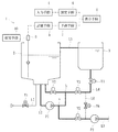
以上、本実施形態について説明したが、本発明はこれに限定されず、例えば図20に示すように、所定量の透析用粉末剤を収容する収容手段Mと、収容手段M内の透析用粉末剤を所定量ずつ溶解槽Tに供給し得るフィーダFと、収容手段M内の透析用粉末の重量を経時的に計測し得る重量計Sとを有した溶解装置に適用してもよい。この場合、追加の透析用粉末剤は、収容手段Mに対して投入されることとなり、その実績投入タイミングが記憶されるとともに予測投入タイミングを予測して表示手段8にて表示させることができる。 Although the present embodiment has been described above, the present invention is not limited to this, and as shown in FIG. 20, for example, a storage means M for storing a predetermined amount of dialysis powder and a dialysis powder in the storage means M. It may be applied to a dissolving device having a feeder F capable of supplying a predetermined amount of the agent to the dissolving tank T and a weighing scale S capable of measuring the weight of the dialysis powder in the accommodating means M over time. In this case, the additional dialysis powder is charged to the accommodating means M, the actual charging timing is stored, and the predicted charging timing can be predicted and displayed on the display means 8.
さらに、本実施形態に係る溶解装置1は、透析用粉末剤を投入して溶解するための第1溶解槽2及び第2溶解槽3を具備しているが、1つの溶解槽を具備したもの或いは3つ以上の溶解槽を具備したものに適用してもよい。また、記憶手段5は、曜日毎に実績投入タイミングを記憶し、曜日毎に表示手段8にて予測投入タイミングを表示しているが、医療施設における患者の治療日程に対応した特定の治療日毎であれば、他の日程であってもよい。
Further, the
過去の透析治療中における追加の透析用粉末剤を投入したタイミングを実績投入タイミングとして記憶し得る記憶手段と、記憶手段で記憶された実績投入タイミングに基づいて、これから行われる透析治療中における追加の透析用粉末剤を投入するタイミングを予測投入タイミングとして予測し得る予測手段と、予測手段で予測された予測投入タイミングを表示し得る表示手段とを具備した溶解装置であれば、外観形状が異なるもの或いは他の機能が付加されたもの等にも適用することができる。 Based on the storage means that can memorize the timing of adding the additional dialysis powder during the past dialysis treatment as the actual input timing and the actual input timing memorized by the storage means, the additional dialysis treatment to be performed in the future. If the dissolution device is provided with a predicting means capable of predicting the timing of charging the dialysis powder as a predicted charging timing and a display means capable of displaying the predicted charging timing predicted by the predicting means, the appearance shape is different. Alternatively, it can be applied to those to which other functions are added.
1 溶解装置
2 第1溶解槽
3 第2溶解槽
4 入力手段
5 記憶手段
6 設定手段
7 予測手段
8 表示手段
9 液位検出手段
10 報知手段
L1 給水ライン
L2 接続ライン
L3 送液ライン
L4 接続ライン
L5 オーバーフローライン
A 透析装置
B 透析液供給装置
1
Claims (6)
過去の透析治療中における追加の透析用粉末剤を投入したタイミングを実績投入タイミングとして記憶する記憶手段と、
前記記憶手段で記憶された実績投入タイミングに基づいて、これから行われる透析治療中における追加の透析用粉末剤を投入するタイミングを予測投入タイミングとして予測する予測手段と、
前記予測手段で予測されたタイミングであって透析治療中における追加の透析用粉末剤を投入するタイミングである前記予測投入タイミングを表示する表示手段と、
を具備したことを特徴とする溶解装置。 A plurality of dialysis devices for providing dialysis treatment to a patient during dialysis treatment, provided with a dissolution tank capable of dissolving a dialysis powder to obtain a dialysis stock solution and accommodating a predetermined amount of the dissolved dialysis stock solution. In a dissolution device capable of dissolving by adding an additional dialysis powder in predetermined amounts as the undiluted solution for dialysis in the dissolution tank is sent to the side.
A storage means for storing the timing of adding additional dialysis powder during past dialysis treatment as the actual input timing,
Based on the actual input timing stored in the storage means, a predictive means for predicting the timing of adding additional dialysis powder during the dialysis treatment to be performed as a predicted input timing, and
A display means for displaying the predicted injection timing, which is the timing predicted by the predictive means and is the timing for adding the additional dialysis powder during the dialysis treatment .
A melting device characterized by being provided with.
前記液位検出手段で検出された透析用原液の液位に基づいて前記透析用粉末剤の追加投入タイミングを報知し得る報知手段と、
を具備するとともに、前記予測手段は、前記報知手段で報知された追加投入タイミングに基づいて次回以降の前記予測投入タイミングを修正し、その修正された予測投入タイミングを前記表示手段にて表示させ得ることを特徴とする請求項2又は3記載の溶解装置。 A liquid level detecting means capable of continuously and in real time detecting the liquid level of the stock solution for dialysis contained in the dissolution tank.
A notification means capable of notifying the timing of additional addition of the dialysis powder based on the liquid level of the dialysis stock solution detected by the liquid level detecting means, and
The predictive means can modify the predicted input timing from the next time onward based on the additional input timing notified by the notification means, and display the corrected predicted input timing on the display means. The melting device according to claim 2 or 3, wherein the melting device is characterized by the above.
Priority Applications (2)
| Application Number | Priority Date | Filing Date | Title |
|---|---|---|---|
| JP2017054678A JP6831279B2 (en) | 2017-03-21 | 2017-03-21 | Melting device |
| CN201810235876.2A CN108619925B (en) | 2017-03-21 | 2018-03-21 | Dissolving device |
Applications Claiming Priority (1)
| Application Number | Priority Date | Filing Date | Title |
|---|---|---|---|
| JP2017054678A JP6831279B2 (en) | 2017-03-21 | 2017-03-21 | Melting device |
Publications (2)
| Publication Number | Publication Date |
|---|---|
| JP2018153557A JP2018153557A (en) | 2018-10-04 |
| JP6831279B2 true JP6831279B2 (en) | 2021-02-17 |
Family
ID=63696158
Family Applications (1)
| Application Number | Title | Priority Date | Filing Date |
|---|---|---|---|
| JP2017054678A Active JP6831279B2 (en) | 2017-03-21 | 2017-03-21 | Melting device |
Country Status (2)
| Country | Link |
|---|---|
| JP (1) | JP6831279B2 (en) |
| CN (1) | CN108619925B (en) |
Families Citing this family (1)
| Publication number | Priority date | Publication date | Assignee | Title |
|---|---|---|---|---|
| CN114051418A (en) | 2019-06-26 | 2022-02-15 | 日机装株式会社 | Blood purification system and solution preparation determination device |
Family Cites Families (14)
| Publication number | Priority date | Publication date | Assignee | Title |
|---|---|---|---|---|
| US4293845A (en) * | 1980-04-17 | 1981-10-06 | Villa Real Antony Euclid C | Electronic multi-patient medication-time-intake programmer and alarm system |
| DE3335301C2 (en) * | 1983-06-25 | 1985-05-02 | Udo 8500 Nürnberg Simon | Drug container |
| CN2114653U (en) * | 1990-10-27 | 1992-09-02 | 中国人民解放军第一四八医院 | Full automatic liquid matching machine |
| JP2001232173A (en) * | 2000-02-28 | 2001-08-28 | Fuji Photo Film Co Ltd | Treating agent dissolving device |
| DE102005025516A1 (en) * | 2005-06-03 | 2006-12-07 | Fresenius Medical Care Deutschland Gmbh | Medical treatment system with a device for providing patient-related data |
| US20070038889A1 (en) * | 2005-08-11 | 2007-02-15 | Wiggins Robert D | Methods and systems to access process control log information associated with process control systems |
| JP4904077B2 (en) * | 2006-04-26 | 2012-03-28 | 日機装株式会社 | Blood purification equipment |
| CN101342389B (en) * | 2008-09-03 | 2010-06-02 | 荣维淳 | Full-automatic liquid preparation machine |
| DE102012004886A1 (en) * | 2012-03-10 | 2013-09-12 | Manfred Völker | Mixing device for the production of ready-to-use medical rinsing solutions, in particular for the hemodialysis concentrates |
| JP6435127B2 (en) * | 2014-07-15 | 2018-12-05 | 日機装株式会社 | Melting equipment |
| JP6424031B2 (en) * | 2014-07-15 | 2018-11-14 | 日機装株式会社 | Melting equipment |
| EP3009183B1 (en) * | 2014-10-15 | 2017-01-11 | Dunschat, Christoph | Dialysis concentrate manufacturing assembly |
| CN204768324U (en) * | 2015-06-12 | 2015-11-18 | 安徽美欣制药有限公司 | Intelligence heat preservation agitator |
| CN105964176A (en) * | 2016-06-28 | 2016-09-28 | 大唐南京发电厂 | System and method for automatically preparing flocculant solution |
-
2017
- 2017-03-21 JP JP2017054678A patent/JP6831279B2/en active Active
-
2018
- 2018-03-21 CN CN201810235876.2A patent/CN108619925B/en active Active
Also Published As
| Publication number | Publication date |
|---|---|
| JP2018153557A (en) | 2018-10-04 |
| CN108619925B (en) | 2021-11-09 |
| CN108619925A (en) | 2018-10-09 |
Similar Documents
| Publication | Publication Date | Title |
|---|---|---|
| JP4769198B2 (en) | Mechanical system | |
| US9509963B2 (en) | Independent wireless dialysis instrument monitoring system and method using camera with programmable camera control mechanism | |
| JP6360332B2 (en) | Feed pump | |
| JP6831279B2 (en) | Melting device | |
| JP4475466B2 (en) | Dissolving apparatus and dissolving method therefor | |
| EP3222303A1 (en) | Dialysis-fluid supply system | |
| JP2017169779A (en) | Dissolution apparatus | |
| JP6435127B2 (en) | Melting equipment | |
| JP2021000354A (en) | Dissolving apparatus | |
| JP4975340B2 (en) | Dissolving apparatus and dissolving method therefor | |
| JP4812116B2 (en) | Dissolution system and dissolution method using the same | |
| JP2006051244A (en) | System for supporting infusion of medicine or the like in home | |
| EP3130369A1 (en) | Drug injection device, medical support system employing same, and medical support method | |
| JP6424031B2 (en) | Melting equipment | |
| JP2019022754A (en) | Dissolution device | |
| JP2020086964A (en) | Monitoring system, information terminal, and monitoring program | |
| JP2014057754A (en) | Medicine preparation support device, medicine preparation support system and medicine preparation support method | |
| JP5870403B2 (en) | Drug packaging device | |
| CA3166418C (en) | Compensation for missing readings from a glucose monitor in an automated insulin delivery system | |
| JP6861075B2 (en) | Dissolving device for dialysis powder and dissolving method for dialysis powder | |
| JP2013180067A (en) | Liquid medicine dispenser | |
| MS et al. | Movable Automatic Medicine Reminder and Indicator Using Arduino. | |
| JPH03132808A (en) | Numerical controller | |
| TW202110498A (en) | Blood purification system and raw liquid preparation determination device | |
| JP2013141583A (en) | Notification system and activities quantity meter |
Legal Events
| Date | Code | Title | Description |
|---|---|---|---|
| A621 | Written request for application examination |
Free format text: JAPANESE INTERMEDIATE CODE: A621 Effective date: 20191121 |
|
| A977 | Report on retrieval |
Free format text: JAPANESE INTERMEDIATE CODE: A971007 Effective date: 20200908 |
|
| A131 | Notification of reasons for refusal |
Free format text: JAPANESE INTERMEDIATE CODE: A131 Effective date: 20201019 |
|
| A521 | Request for written amendment filed |
Free format text: JAPANESE INTERMEDIATE CODE: A523 Effective date: 20201217 |
|
| TRDD | Decision of grant or rejection written | ||
| A01 | Written decision to grant a patent or to grant a registration (utility model) |
Free format text: JAPANESE INTERMEDIATE CODE: A01 Effective date: 20210122 |
|
| A61 | First payment of annual fees (during grant procedure) |
Free format text: JAPANESE INTERMEDIATE CODE: A61 Effective date: 20210128 |
|
| R150 | Certificate of patent or registration of utility model |
Ref document number: 6831279 Country of ref document: JP Free format text: JAPANESE INTERMEDIATE CODE: R150 |
|
| R250 | Receipt of annual fees |
Free format text: JAPANESE INTERMEDIATE CODE: R250 |