JP6828602B2 - Target detection device - Google Patents
Target detection device Download PDFInfo
- Publication number
- JP6828602B2 JP6828602B2 JP2017114775A JP2017114775A JP6828602B2 JP 6828602 B2 JP6828602 B2 JP 6828602B2 JP 2017114775 A JP2017114775 A JP 2017114775A JP 2017114775 A JP2017114775 A JP 2017114775A JP 6828602 B2 JP6828602 B2 JP 6828602B2
- Authority
- JP
- Japan
- Prior art keywords
- target
- sensor
- sensor target
- detected
- vehicle
- Prior art date
- Legal status (The legal status is an assumption and is not a legal conclusion. Google has not performed a legal analysis and makes no representation as to the accuracy of the status listed.)
- Active
Links
Images


Landscapes
- Traffic Control Systems (AREA)
- Radar Systems Or Details Thereof (AREA)
Description
本発明は、車両(自車両)の周辺に存在する立体物(例えば、他の車両)の幅及び長さ等の物標情報を取得する物標検出装置に関する。 The present invention relates to a target detection device that acquires target information such as the width and length of a three-dimensional object (for example, another vehicle) existing around a vehicle (own vehicle).
従来から、車線変更を行うための操舵操作(ハンドル操作)を支援する車線変更支援装置が知られている(例えば、特許文献1を参照。)。車線変更支援装置は、車両に備えられた複数のレーダセンサ(例えば、ミリ波レーダやレーザレーダなど)によって、車両の周囲に存在する立体物(例えば、他車両)を検出し、その立体物の自車両に対する「縦位置、横位置及び相対車速」、並びに、その立体物の「幅及び長さ」等の情報(以下、「物標情報」とも称呼する。)を取得する。そして、車線変更支援装置は、取得した物標情報に基づいて、自車両が車線変更を行っても安全であるかどうかを監視し、安全であると判定した場合に車線変更支援を実行する。このような、「自車両の周辺に存在する立体物の物標情報を取得する物標検出装置」は、車線変更支援装置に限らず、他の運転支援装置にも採用される。 Conventionally, a lane change support device that supports a steering operation (steering wheel operation) for changing lanes has been known (see, for example, Patent Document 1). The lane change support device detects a three-dimensional object (for example, another vehicle) existing around the vehicle by a plurality of radar sensors (for example, millimeter-wave radar and laser radar) provided in the vehicle, and the three-dimensional object is detected. Obtains information such as "vertical position, horizontal position and relative vehicle speed" for the own vehicle and "width and length" of the three-dimensional object (hereinafter, also referred to as "target information"). Then, the lane change support device monitors whether or not the own vehicle is safe even if the vehicle changes lanes based on the acquired target information, and executes lane change support when it is determined that the vehicle is safe. Such a "target detection device that acquires target information of a three-dimensional object existing around the own vehicle" is adopted not only in the lane change support device but also in other driving support devices.
ところで、レーダセンサは、周知であるように、自身の周囲にレーダ波を送信し且つそのレーダ波が立体物によって反射されることにより生成される反射波を受信し、その受信した反射波に基づいて物標を認識し且つ物標情報を取得する。このため、自車両に搭載されているレーダセンサの検知範囲、性能及び周辺環境の少なくとも一つによって、自車両の周囲に存在する物標が一時的に検知されないことが生じ得るため、自車両の周囲の物標の存在を正確に判断できない可能性がある。 By the way, as is well known, a radar sensor transmits a radar wave around itself, receives a reflected wave generated by the radar wave being reflected by a three-dimensional object, and is based on the received reflected wave. Recognize the target and acquire the target information. For this reason, the detection range, performance, and at least one of the surrounding environment of the radar sensor mounted on the own vehicle may temporarily prevent the target existing around the own vehicle from being detected. It may not be possible to accurately determine the presence of surrounding objects.
そのため、従来の物標検出装置において、レーダセンサによって、物標が検知されなくなった後、物標が再検知されない限り、外挿処理を行うことにより途切れない物体検知を実行することが行われている。更に、従来の物標検出装置において、外挿処理を一定の最大外挿継続時間以上行ったときに、外挿処理を行ったセンサ物標が存在しないと判定することが行われている。 Therefore, in the conventional target detection device, after the target is no longer detected by the radar sensor, uninterrupted object detection is performed by performing extrapolation processing unless the target is re-detected. There is. Further, in the conventional target detection device, when the extrapolation process is performed for a certain maximum extrapolation duration or longer, it is determined that the sensor target for which the extrapolation process has been performed does not exist.
尚、外挿処理(単に「外挿」と称呼される場合がある。)とは、検知されていた物標の検知されていたときの物標情報又は当該物標情報に基づいて推定した物標情報に基づいて、検知されなくなった物標の物標情報を推定し、検知されなくなった物標の物標情報を推定した物標情報によって置換することによって物標を外挿する処理のことをいう。 The extrapolation process (sometimes referred to simply as "extrapolation") is the target information of the detected target when it was detected or an estimated value based on the target information. A process of extrapolating a target by estimating the target information of the undetected target based on the target information and replacing the target information of the undetected target with the estimated target information. To say.
ところが、物標の外挿処理を行う最大外挿継続時間を一定にすることによって、次のような問題が生じてしまうことがあり得る。
・ノイズ及びゴースト等の一時的に誤検知した物標も、検知されなくなった後、一定時間外挿してしまう。これによって、実際には、物標が自車両周囲に存在しない可能性が高いのに、物標が存在するとの判定が必要以上に長い間継続してしまう。
・物標の自車両に対する相対速度が小さい場合、自車両の近傍のレーダセンサの死角に侵入してから脱出するまでの間の時間と比べて最大外挿継続時間が短くなってしまうことがあり得る。この場合、物標がレーダセンサの死角にとどまっている間に外挿が終了してしまい、物標が自車両の近傍に存在しているのに存在していないと誤判定されることがあり得る。
However, by setting the maximum extrapolation duration for extrapolating the target to be constant, the following problems may occur.
-Temporarily falsely detected targets such as noise and ghosts are also extrapolated for a certain period of time after they are no longer detected. As a result, although there is a high possibility that the target does not actually exist around the own vehicle, the determination that the target exists continues for an unnecessarily long time.
・ If the relative speed of the target with respect to the own vehicle is small, the maximum extrapolation duration may be shorter than the time between entering the blind spot of the radar sensor near the own vehicle and escaping. obtain. In this case, the extrapolation may be completed while the target remains in the blind spot of the radar sensor, and it may be erroneously determined that the target exists in the vicinity of the own vehicle but does not exist. obtain.
更に、従来装置において、物標が継続して検知される継続演算回数に比例して、一定の上昇率にて増加するパラメータ(以下、「存在確率」とも称呼される。)の大きさが大きくなるほど、最大外挿継続時間が、長くなるように設定されることが行われている。 Further, in the conventional device, the magnitude of the parameter (hereinafter, also referred to as “existence probability”) that increases at a constant rate of increase in proportion to the number of continuous operations in which the target is continuously detected is large. Indeed, the maximum extrapolation duration is set to be long.
ところが、一箇所に長時間滞留するような特性を有する誤検知された物標(例えば、壁、路面及び路側物等のそれぞれが移動物であると誤検知された物標)は、自車両に対する相対位置が同じ位置に長い間検知され続ける傾向がある。このため、そのような誤検知された物標の存在確率が高くなってしまうことに伴い最大外挿継続時間も長く設定され、誤検知物標が検知されなくなった後、必要以上に長時間外挿されることにより、長時間誤検知物標が存在すると判定されてしまうことがあり得る。そして、その誤検知物標の検知位置が誤検知され、例えば、誤検知された位置が車線上にある場合、長い間その車線上に誤検知物標が存在すると判定されてしまうことがあり得る。 However, an erroneously detected target having a characteristic of staying in one place for a long time (for example, a target erroneously detected that each of a wall, a road surface, a roadside object, etc. is a moving object) is a target for the own vehicle. Relative positions tend to stay in the same position for a long time. For this reason, the maximum extrapolation duration is set longer as the existence probability of such a falsely detected target increases, and after the falsely detected target is no longer detected, it is outside for an unnecessarily long time. By being inserted, it may be determined that a false positive target exists for a long time. Then, the detection position of the false detection target is falsely detected, and for example, when the false detection position is on the lane, it may be determined that the false detection target exists on the lane for a long time. ..
本発明は上述した課題に対処するためになされた。即ち、本発明の目的の一つは、検出されていた物標の種類に応じて適切な最大外挿継続時間を設定することができ、正確又は適切な物標の存在判定を行うことができる物標検出装置(以下、「本発明装置」とも称呼する。)を提供することにある。 The present invention has been made to address the above-mentioned problems. That is, one of the objects of the present invention is that an appropriate maximum extrapolation duration can be set according to the type of the detected target, and the existence of an accurate or appropriate target can be determined. An object of the present invention is to provide a target detection device (hereinafter, also referred to as “the device of the present invention”).
本発明装置は、それぞれが、自車両の周囲に送信するレーダ波の立体物による反射点をセンサ物標として検出し、前記検出したセンサ物標の前記自車両に対する縦距離、横位置及び相対速度を含むセンサ物標情報を取得するための位置速度情報と、を検出する複数のレーダセンサ(16FC、16FL、16FR、16RL及び16RR)と、
前記検出されたセンサ物標の存在確率を演算する(ステップ1015)存在確率演算手段(10)と、
検出されていた前記センサ物標が検出されなくなった場合、当該検出されていた前記センサ物標が再検出されない限り、前記検出されていたセンサ物標が検出されていたときの前記位置速度情報に基づくセンサ物標情報に基づいて前記検出されていたセンサ物標の前記センサ物標情報を推定することによって外挿されたセンサ物標を生成する外挿処理(ステップ1030)を行う外挿処理手段(10)と、
前記存在確率及び前記検出されていたセンサ物標の縦相対速度(Vxobj)に基づいて前記外挿処理を行う時間の最大値である最大外挿継続時間を演算する(ステップ1025)最大外挿継続時間演算手段と、
前記外挿処理を最大外挿継続時間以上行ったとき(ステップ1040にて「Yes」との判定)に当該外挿処理を行った前記センサ物標が存在しないと判定する(ステップ1045)センサ物標存在判定手段(10)と、
を備え、
前記存在確率演算手段は、
前記センサ物標が検出されている場合に当該センサ物標の縦相対速度の大きさ(|Vxobj|)が大きくなるほど前記存在確率の上昇率が大きくなるように当該センサ物標の縦相対速度に基づいて当該存在確率の上昇率を求める(BK1)とともに、前記センサ物標が継続して検出されている時間に対応する値と前記存在確率の上昇率とに基づいて決定される前記存在確率の増大量を積算することによって前記存在確率を算出する(ステップ1015)ように構成され、
前記最大外挿継続時間演算手段は、
前記存在確率が大きくなるほど前記最大外挿継続時間が長くなり、且つ、前記縦相対速度の大きさが小さくなるほど前記最大外挿継続時間が長くなるよう(BK2)に、前記最大外挿継続時間を演算する(ステップ1025)ように構成されている。
Each device of the present invention detects the reflection point of the radar wave transmitted around the own vehicle by a three-dimensional object as a sensor target, and the vertical distance, the horizontal position, and the relative speed of the detected sensor target with respect to the own vehicle. A plurality of radar sensors (16FC, 16FL, 16FR, 16RL and 16RR) for detecting position and velocity information for acquiring sensor target information including
The existence probability calculation means (10) for calculating the existence probability of the detected sensor target (step 1015),
When the detected sensor target is no longer detected, the position / velocity information at the time when the detected sensor target is detected is used as long as the detected sensor target is not re-detected. Extrapolation processing means for performing extrapolation processing (step 1030) to generate an extrapolated sensor target by estimating the sensor target information of the detected sensor target based on the sensor target information based on the sensor target information. (10) and
The maximum extrapolation duration, which is the maximum value of the extrapolation processing time, is calculated based on the existence probability and the vertical relative velocity (Vxobj) of the detected sensor target (step 1025). Time calculation means and
When the extrapolation process is performed for the maximum extrapolation duration or longer (determined as "Yes" in step 1040), it is determined that the sensor target for which the extrapolation process has been performed does not exist (step 1045). Mark existence determination means (10) and
With
The existence probability calculation means
When the sensor target is detected, the vertical relative speed of the sensor target is increased so that the increase rate of the existence probability increases as the magnitude (| Vxobj |) of the vertical relative speed of the sensor target increases. The increase rate of the existence probability is obtained based on (BK1), and the existence probability is determined based on the value corresponding to the time during which the sensor target is continuously detected and the increase rate of the existence probability. It is configured to calculate the existence probability by integrating the increase amount (step 1015).
The maximum extrapolation duration calculation means is
The maximum extrapolation duration is set so that the maximum extrapolation duration becomes longer as the existence probability increases, and the maximum extrapolation duration becomes longer as the magnitude of the longitudinal relative velocity decreases (BK2). It is configured to calculate (step 1025).
これによれば、センサ物標の種類に応じた適切な最大外挿継続時間を設定することができ、以て、正確又は適切なセンサ物標の存在判定を行うことができる。 According to this, an appropriate maximum extrapolation duration can be set according to the type of the sensor target, and therefore, the existence of the sensor target can be accurately or appropriately determined.
上記説明においては、本発明の理解を助けるために、後述する実施形態に対応する発明の構成に対し、その実施形態で用いた名称及び/又は符号を括弧書きで添えている。しかしながら、本発明の各構成要素は、上記名称及び/又は符号によって規定される実施形態に限定されるものではない。本発明の他の目的、他の特徴及び付随する利点は、以下の図面を参照しつつ記述される本発明の実施形態についての説明から容易に理解されるであろう。 In the above description, in order to help the understanding of the present invention, the names and / or symbols used in the embodiments are added in parentheses to the configurations of the invention corresponding to the embodiments described later. However, each component of the present invention is not limited to the embodiment defined by the above name and / or reference numeral. Other objects, other features and accompanying advantages of the present invention will be readily understood from the description of embodiments of the present invention described with reference to the following drawings.
以下、本発明の実施形態に係る物標検出装置について図面を参照しながら説明する。この物標検出装置は、運転支援制御装置(車両走行制御装置)の一部である車線変更支援装置(以下、「本実施装置」とも称呼される。)に組み込まれている。 Hereinafter, the target detection device according to the embodiment of the present invention will be described with reference to the drawings. This target detection device is incorporated in a lane change support device (hereinafter, also referred to as "this implementation device") which is a part of a driving support control device (vehicle travel control device).
(構成)
本実施装置は、図1に示したように、車両(以下において、他の車両と区別するために、「自車両」と称呼される。)に適用され、運転支援ECU10、エンジンECU30、ブレーキECU40、ステアリングECU50、メータECU60及び表示ECU70を備えている。尚、以下において、運転支援ECU10は、単に、「DSECU」とも称呼される。
(Constitution)
As shown in FIG. 1, the present implementation device is applied to a vehicle (hereinafter, referred to as "own vehicle" to distinguish it from other vehicles), and is applied to a
これらのECUは、マイクロコンピュータを主要部として備える電気制御装置(Electric Control Unit)であり、図示しないCAN(Controller Area Network)を介して相互に情報を送信可能及び受信可能に接続されている。本明細書において、マイクロコンピュータは、CPU、ROM、RAM、不揮発性メモリ及びインターフェースI/F等を含む。CPUはROMに格納されたインストラクション(プログラム、ルーチン)を実行することにより各種機能を実現するようになっている。これらのECUは、幾つか又は全部が一つのECUに統合されてもよい。 These ECUs are electric control units (Electric Control Units) including a microcomputer as a main part, and are connected to each other so as to be able to transmit and receive information via a CAN (Controller Area Network) (not shown). In the present specification, the microcomputer includes a CPU, ROM, RAM, non-volatile memory, interface I / F, and the like. The CPU realizes various functions by executing instructions (programs, routines) stored in ROM. Some or all of these ECUs may be integrated into one ECU.
DSECUは、以下に列挙するセンサ(スイッチを含む。)と接続されていて、それらのセンサの検出信号又は出力信号を受信するようになっている。尚、各センサは、DSECU以外のECUに接続されていてもよい。その場合、DSECUは、センサが接続されたECUからCANを介してそのセンサの検出信号又は出力信号を受信する。 The DSECU is connected to the sensors (including switches) listed below and is adapted to receive detection signals or output signals of those sensors. Each sensor may be connected to an ECU other than the DSECU. In that case, the DSECU receives the detection signal or the output signal of the sensor from the ECU to which the sensor is connected via the CAN.
アクセルペダル11aの操作量APを検出するアクセルペダル操作量センサ11。
ブレーキペダル12aの操作量BPを検出するブレーキペダル操作量センサ12。
操舵ハンドルSWの操舵角θを検出する操舵角センサ13。
操舵ハンドルSWの操作により自車両のステアリングシャフトUSに加わる操舵トルクTraを検出する操舵トルクセンサ14。
自車両の走行速度(車速)を検出し、自車両の前後方向の速度(即ち、縦速度)である車速Vsxを検出する車速センサ15。
周辺レーダセンサ16a及びカメラセンサ16bを含む周辺センサ16。
操作スイッチ17。
自車両SVのヨーレートYRtを検出するヨーレートセンサ18。
自車両SVの前後方向の加速度Gxを検出する前後加速度センサ19。
自車両SVの横(車幅)方向(自車両SVの中心軸線に直交する方向)の加速度Gyを検出する横加速度センサ20。
Accelerator pedal operation amount sensor 11 that detects the operation amount AP of the
Brake pedal
A
A
A
A front-
The
周辺レーダセンサ16aは、図2に示したように、中央前方周辺センサ16FC、右前方周辺センサ16FR、左前方周辺センサ16FL、右後方周辺センサ16RR、及び、左後方周辺センサ16RLを備えている。周辺レーダセンサ16aは、単に、「レーダセンサ」と称呼される場合がある。
As shown in FIG. 2, the
周辺センサ16FC,16FR,16FL,16RR及び16RLを個々に区別する必要が無い場合には、それらは周辺レーダセンサ16aと称呼される。周辺センサ16FC,16FR,16FL,16RR及び16RLは、実質的に互いに同一の構成を有する。
Peripheral sensors 16FC, 16FR, 16FL, 16RR and 16RL are referred to as
周辺レーダセンサ16aは、レーダ送受信部と信号処理部(図示略)とを備えている。レーダ送受信部は、ミリ波帯の電波であるレーダ波(以下、「ミリ波」と称呼する。)を放射し、更に、放射範囲内に存在する立体物(例えば、他車両、歩行者、自転車及び建造物等)によって反射されたミリ波(即ち、反射波)を受信する。レーダ波を反射する立体物の点は「反射点」とも称呼される。
The
信号処理部は、送信したミリ波と受信した反射波との位相差、それらの周波数差、及び、反射波の減衰レベル及びミリ波を送信してから反射波を受信するまでの時間等に基づいて、自車両SVと立体物の反射点との距離、自車両SVと立体物の反射点との相対速度、及び、自車両SVに対する立体物の反射点の方位、を表す反射点情報を所定時間が経過する毎に取得(検出)する。この立体物の反射点は物標と見做され、且つ、「センサ物標」と称呼される。 The signal processing unit is based on the phase difference between the transmitted millimeter wave and the received reflected wave, their frequency difference, the attenuation level of the reflected wave, the time from the transmission of the millimeter wave to the reception of the reflected wave, and the like. Therefore, the reflection point information indicating the distance between the own vehicle SV and the reflection point of the three-dimensional object, the relative speed between the own vehicle SV and the reflection point of the three-dimensional object, and the direction of the reflection point of the three-dimensional object with respect to the own vehicle SV is predetermined. Acquire (detect) every time the time elapses. The reflection point of this three-dimensional object is regarded as a target and is also called a "sensor target".
中央前方周辺センサ16FCは、車体のフロント中央部に設けられ、自車両SVの前方領域に存在するセンサ物標を検出する。右前方周辺センサ16FRは、車体の右前コーナー部に設けられ、主に自車両SVの右前方領域に存在するセンサ物標を検出する。左前方周辺センサ16FLは、車体の左前コーナー部に設けられ、主に自車両SVの左前方領域に存在するセンサ物標を検出する。右後方周辺センサ16RRは、車体の右後コーナー部に設けられ、主に自車両SVの右後方領域に存在するセンサ物標を検出する。左後方周辺センサ16RLは、車体の左後コーナー部に設けられ、主に自車両SVの左後方領域に存在するセンサ物標を検出する。例えば、周辺レーダセンサ16aは、自車両SVからの距離が100メートル程度の範囲に入るセンサ物標を検出する。尚、周辺レーダセンサ16aはミリ波帯以外の周波数帯の電波(レーダ波)を用いるレーダセンサであってもよい。
The center front peripheral sensor 16FC is provided in the front center portion of the vehicle body and detects a sensor target existing in the front region of the own vehicle SV. The right front peripheral sensor 16FR is provided at the right front corner of the vehicle body, and mainly detects a sensor target existing in the right front region of the own vehicle SV. The left front peripheral sensor 16FL is provided at the left front corner of the vehicle body, and mainly detects a sensor target existing in the left front region of the own vehicle SV. The right rear peripheral sensor 16RR is provided at the right rear corner of the vehicle body, and mainly detects a sensor target existing in the right rear region of the own vehicle SV. The left rear peripheral sensor 16RL is provided at the left rear corner of the vehicle body, and mainly detects a sensor target existing in the left rear region of the own vehicle SV. For example, the
DSECUは、図2に示したように、X−Y座標を規定している。X軸は、自車両SVの前後方向に沿って自車両SVの前端部の幅方向中心位置を通るように伸び、前方を正の値として有する座標軸である。Y軸は、X軸と直交し、自車両SVの左方向を正の値として有する座標軸である。X軸の原点及びY軸の原点は、自車両SVの前端部の幅方向中心位置である。 As shown in FIG. 2, the DSECU defines the XY coordinates. The X-axis is a coordinate axis that extends along the front-rear direction of the own vehicle SV so as to pass through the center position in the width direction of the front end portion of the own vehicle SV and has the front as a positive value. The Y-axis is a coordinate axis that is orthogonal to the X-axis and has a positive value in the left direction of the own vehicle SV. The origin of the X-axis and the origin of the Y-axis are the center positions in the width direction of the front end portion of the own vehicle SV.
周辺レーダセンサ16aは、上述した反射点情報に基づいて、以下に述べる「センサ物標についての情報」をDSECUに所定時間(演算周期)が経過する毎に送信する。センサ物標についての情報は、以下、「センサ物標情報」と称呼される。なお、DSECUは、演算周期が経過する毎に、上述した反射点情報を周辺レーダセンサ16aから直接取得して、反射点情報に基づいて「センサ物標情報」を演算して求めるようにして、センサ物標情報を取得してもよい。
Based on the above-mentioned reflection point information, the
・センサ物標のX座標位置(Xobj)。即ち、自車両SVとセンサ物標とのX軸方向の符号付き距離。X座標位置Xobjは、縦距離Xobj又は縦位置Xobjとも称呼される。
・センサ物標のY座標位置(Yobj)。即ち、自車両SVとセンサ物標とのY軸方向の符号付き距離。Y座標位置Yobjは、横位置Yobjとも称呼される。
・センサ物標の自車両SVに対するX軸方向の速度(即ち、縦相対速度)Vxobj。尚、縦絶対速度Vaxobjは、縦相対速度Vxobjに自車両SVの車速Vが加えられた値である。
・センサ物標の自車両SVに対するY軸方向の速度(即ち、横相対速度)Vyobj。尚、横絶対速度Vayobjは、横相対速度Vyobjと等しい値に設定される。
・センサ物標を識別(特定)するためのセンサ物標識別情報(センサ物標ID)
-X coordinate position (Xobj) of the sensor target. That is, the signed distance between the own vehicle SV and the sensor target in the X-axis direction. The X coordinate position Xobj is also referred to as a vertical distance Xobj or a vertical position Xobj.
-Y coordinate position (Yobj) of the sensor target. That is, the signed distance between the own vehicle SV and the sensor target in the Y-axis direction. The Y coordinate position Yobj is also referred to as a horizontal position Yobj.
-Velocity (that is, vertical relative velocity) Vxobj in the X-axis direction with respect to the own vehicle SV of the sensor target. The vertical absolute speed Vaxobj is a value obtained by adding the vehicle speed V of the own vehicle SV to the vertical relative speed Vxobj.
-Velocity in the Y-axis direction (that is, lateral relative velocity) Vyobj of the sensor target with respect to the own vehicle SV. The lateral absolute velocity Vyobj is set to a value equal to the lateral relative velocity Vyobj.
-Information for each sensor target (sensor target ID) for identifying (identifying) the sensor target
ところで、一つの立体物が二以上の反射点を有する場合がある。従って、周辺レーダセンサ16aのそれぞれは、一つの立体物に対して、複数のセンサ物標を検出する場合がある。即ち、周辺レーダセンサ16aのそれぞれは、複数組のセンサ物標情報を取得する場合がある。更に、二以上の周辺レーダセンサ16aが、一つの立体物に対して複数組のセンサ物標情報を取得する場合がある。
By the way, one three-dimensional object may have two or more reflection points. Therefore, each of the
そこで、DSECUは、一つの立体物を検出している可能性が高い複数のセンサ物標をグルーピング(統合、フュージョン)することにより、複数のセンサ物標が示す一つの物標(以下、「フュージョン物標」と称呼される。)を認識する。 Therefore, the DSECU groups (integrates, fuses) a plurality of sensor targets that are likely to detect one three-dimensional object, thereby indicating one target indicated by the plurality of sensor targets (hereinafter, "fusion"). It is called a "target").
更に、DSECUは、その「フュージョン物標の属性値(属性値についての情報)」を後述するように取得する。フュージョン物標の属性値についての情報は「フュージョン物標情報又はフュージョン物標属性値」と称呼され、以下に述べる情報を含む。 Further, the DSECU acquires the "attribute value (information about the attribute value) of the fusion target" as described later. The information about the attribute value of the fusion target is referred to as "fusion target information or fusion target attribute value" and includes the information described below.
・フュージョン物標のX座標位置(Xf)。即ち、自車両SVとフュージョン物標とのX軸方向の符号付き距離。本例において、X座標位置Xfは、フュージョン物標の中心点のX座標位置である。
・フュージョン物標のY座標位置(Yf)。即ち、自車両SVとフュージョン物標とのY軸方向の符号付き距離。本例において、Y座標位置Yfは、フュージョン物標の中心点のY座標位置である。
・フュージョン物標の自車両SVに対するX軸方向の速度(即ち、縦相対速度)Vxf。
・フュージョン物標の自車両SVに対するY軸方向の速度(即ち、横相対速度)Vyf。
・フュージョン物標の長さLf(フュージョン物標のX軸方向の長さ)。
・フュージョン物標の幅Wf(フュージョン物標のY軸方向の長さ)。
・フュージョン物標を識別(特定)するためのフュージョン物標識別情報(フュージョン物標ID)
-X coordinate position (Xf) of the fusion target. That is, the signed distance between the own vehicle SV and the fusion target in the X-axis direction. In this example, the X coordinate position Xf is the X coordinate position of the center point of the fusion target.
-Y coordinate position (Yf) of the fusion target. That is, the signed distance between the own vehicle SV and the fusion target in the Y-axis direction. In this example, the Y coordinate position Yf is the Y coordinate position of the center point of the fusion target.
-Velocity (that is, vertical relative velocity) Vxf in the X-axis direction with respect to the own vehicle SV of the fusion target.
-Velocity (that is, lateral relative velocity) Vyf in the Y-axis direction with respect to the own vehicle SV of the fusion target.
-Length of fusion target Lf (length of fusion target in the X-axis direction).
-Width of fusion target Wf (length of fusion target in the Y-axis direction).
-Information for each fusion target (fusion target ID) for identifying (identifying) the fusion target
カメラセンサ16bは、ステレオカメラであるカメラ部、及び、カメラ部によって撮影して得られた画像データを解析して道路の白線を認識するレーン認識部を備えている。カメラセンサ16b(カメラ部)は、自車両SVの前方の風景を撮影する。カメラセンサ16b(レーン認識部)は、所定の角度範囲(自車両SV前方に広がる範囲)を有する画像処理領域の画像データを解析して、自車両SVの前方の道路に形成された白線(区画線)を認識(検出)する。カメラセンサ16bは、認識した白線に関する情報をDSECUに送信する。
The
DSECUは、カメラセンサ16bから供給された情報に基づいて、図3に示したように、自車両SVの走行している車線(以下、「自車線」とも称呼する。)における左右の白線WLの幅方向の中心位置となる車線中心ラインCLを特定する。この車線中心ラインCLは、後述する車線維持支援制御における目標走行ラインとして利用される。更に、DSECUは、車線中心ラインCLのカーブの曲率Cuを演算する。尚、曲率Cuは、車線中心ラインCLが右にカーブしているとき正の値となり、車線中心ラインCLが左にカーブしているとき負の値となるように定義されている。
Based on the information supplied from the
加えて、DSECUは、左白線及び右白線で区画される車線における自車両SVの位置及び向きを演算する。例えば、DSECUは、図3に示したように、自車両SVの基準点P(例えば、重心位置)と車線中心ラインCLとの道路幅方向の符号付き距離Dyを演算する。符号付き距離Dyの大きさは、自車両SVが車線中心ラインCLに対して道路幅方向に偏移している距離を示す。符号付き距離Dyは、自車両SVの基準点Pが車線中心ラインCLに対して道路幅方向の右側に偏移しているとき正の値となり、自車両SVの基準点Pが車線中心ラインCLに対して道路幅方向の左側に偏移しているとき負の値となるように定義されている。この符号付き距離Dyは以下において「横偏差Dy」とも称呼される。 In addition, the DESCU calculates the position and orientation of the own vehicle SV in the lane partitioned by the left white line and the right white line. For example, as shown in FIG. 3, the DESCU calculates the signed distance Dy in the road width direction between the reference point P (for example, the position of the center of gravity) of the own vehicle SV and the lane center line CL. The magnitude of the signed distance Dy indicates the distance at which the own vehicle SV deviates from the lane center line CL in the road width direction. The signed distance Dy becomes a positive value when the reference point P of the own vehicle SV shifts to the right side in the road width direction with respect to the lane center line CL, and the reference point P of the own vehicle SV is the lane center line CL. It is defined to be a negative value when shifting to the left side in the road width direction. This signed distance Dy is also referred to hereinafter as "lateral deviation Dy".
DSECUは、車線中心ラインCLの方向と自車両SVの向いている方向(自車両SVの前後軸の方向)とのなす角度θyを演算する。この角度θyは以下において「ヨー角θy」とも称呼される。ヨー角θyは、自車両SVの向いている方向が車線中心ラインCLの方向に対して右回り側であるとき正の値となり、自車両SVの向いている方向が車線中心ラインCLの方向に対して左回り側であるとき負の値となるように定義されている。以下、曲率Cu、横偏差Dy、及び、ヨー角θyを表す情報(Cu、Dy、θy)は「車線関連車両情報」と称呼される場合がある。 The DESCU calculates the angle θy formed by the direction of the lane center line CL and the direction in which the own vehicle SV is facing (the direction of the front-rear axis of the own vehicle SV). This angle θy is also referred to hereinafter as “yaw angle θy”. The yaw angle θy becomes a positive value when the direction in which the own vehicle SV is facing is clockwise with respect to the direction of the lane center line CL, and the direction in which the own vehicle SV is facing is in the direction of the lane center line CL. On the other hand, it is defined to have a negative value when it is on the counterclockwise side. Hereinafter, the information (Cu, Dy, θy) representing the curvature Cu, the lateral deviation Dy, and the yaw angle θy may be referred to as “lane-related vehicle information”.
カメラセンサ16bは、自車線の左白線及び右白線の種類(例えば、実線であるか破線であるか等)及び白線の形状等についての情報をDSECUに供給する。更に、カメラセンサ16bは、自車線に隣接する車線の左白線及び右白線の種類及び白線の形状等についてもDSECUに供給する。即ち、カメラセンサ16bは、「白線に関する情報」についてもDSECUに供給する。白線が実線である場合、車両がその白線を跨いで車線変更することは禁止されている。一方、白線が破線(一定の間隔で断続的に形成されている白線)の場合、車両がその白線を跨いで車線変更することは許可されている。車線関連車両情報(Cu、Dy、θy)、及び、白線に関する情報は、「車線情報」と称呼される場合がある。
The
操作スイッチ17は、何れも後述する「車線変更支援制御、車線維持制御、及び、追従車間距離制御」のそれぞれを実行するか否かについての選択を行うために運転者により操作される操作器である。従って、操作スイッチ17は、運転者の操作に応じて、上記の各制御の実行が選択されたか否かを示す信号を出力する。加えて、操作スイッチ17は、上記の各制御を実行する際の運転者の好みを反映するためのパラメータを運転者に入力又は選択させる機能も備えている。
The
エンジンECU30は、エンジンアクチュエータ31と接続されている。エンジンアクチュエータ31は、内燃機関の吸入空気量を調整するためのスロットル弁の開度を変更するスロットル弁アクチュエータを含む。エンジンECU30は、エンジンアクチュエータ31を駆動することによって、内燃機関32が発生するトルクを変更することにより、自車両SVの駆動力を制御し加速状態(加速度)を変更することができる。
The
ブレーキECU40は、ブレーキアクチュエータ41に接続されている。ブレーキアクチュエータ41は、ブレーキECU40からの指示に応じて摩擦ブレーキ機構42のブレーキキャリパ42bに内蔵されたホイールシリンダに供給する油圧を調整し、その油圧によりブレーキパッドをブレーキディスク42aに押し付けて摩擦制動力を発生させる。従って、ブレーキECU40は、ブレーキアクチュエータ41を制御することによって、自車両SVの制動力を制御し加速状態(減速度)を変更することができる。
The
ステアリングECU50は、周知の電動パワーステアリングシステムの制御装置であって、モータドライバ51に接続されている。モータドライバ51は、転舵用モータ52に接続されている。転舵用モータ52は、車両の「操舵ハンドル、操舵ハンドルに連結されたステアリングシャフト及び操舵用ギア機構等を含むステアリング機構」に組み込まれている。転舵用モータ52は、モータドライバ51から供給される電力によってトルクを発生し、このトルクによって操舵アシストトルクを加えたり、左右の操舵輪を転舵したりすることができる。即ち、転舵用モータ52は、自車両SVの舵角(転舵輪の転舵角度)を変更することができる。
The steering
ステアリングECU50は、ウインカーレバースイッチ53と接続されている。ウインカーレバースイッチ53は、後述するターンシグナルランプ61を作動(点滅)させるために運転者によって操作されるウインカーレバーの操作位置を検出する検出スイッチである。
The steering
ウインカーレバーはステアリングコラムに設けられている。ウインカーレバーは、初期位置から右回り操作方向に所定角度回転された第1段階位置と、第1段階位置よりも更に所定回転角度だけ右回り操作方向に回転された第2段階位置と、の2つの位置に操作できるようになっている。ウインカーレバーは、右回り操作方向の第1段階位置に運転者によって維持されている限りその位置を維持するが、運転者がウインカーレバーから手を離すと初期位置に自動的に戻るようになっている。ウインカーレバースイッチ53は、ウインカーレバーが右回り操作方向の第1段階位置にあるとき、ウインカーレバーが右回り操作方向の第1段階位置に維持されていることを示す信号をステアリングECU50に出力する。
The blinker lever is provided on the steering column. The winker lever has two positions: a first stage position that is rotated by a predetermined angle in the clockwise operation direction from the initial position, and a second stage position that is rotated in a clockwise operation direction by a predetermined rotation angle from the first stage position. It can be operated in one position. The turn signal lever maintains that position as long as it is maintained in the first stage position in the clockwise operation direction by the driver, but when the driver releases the turn signal lever, it automatically returns to the initial position. There is. The
同様に、ウインカーレバーは、初期位置から左回り操作方向に所定角度回転された第1段階位置と、第1段階位置よりも更に所定回転角度だけ左回り操作方向に回転された第2段階位置と、の2つの位置に操作できるようになっている。ウインカーレバーは、左回り操作方向の第1段階位置に運転者によって維持されている限りその位置を維持するが、運転者がウインカーレバーから手を離すと初期位置に自動的に戻るようになっている。ウインカーレバースイッチ53は、ウインカーレバーが左回り操作方向の第1段階位置にあるとき、ウインカーレバーが左回り操作方向の第1段階位置に維持されていることを示す信号をステアリングECU50に出力する。尚、このようなウインカーレバーについては、例えば、特開2005−138647号公報に開示されている。
Similarly, the winker lever has a first stage position rotated counterclockwise from the initial position by a predetermined angle and a second stage position rotated counterclockwise by a predetermined rotation angle from the first stage position. It can be operated in two positions,, and. The blinker lever maintains its position as long as it is maintained in the first stage position in the counterclockwise operation direction by the driver, but when the driver releases the blinker lever, it automatically returns to the initial position. There is. The
DSECUは、ウインカーレバースイッチ53からの信号に基づいて、ウインカーレバーが右回り操作方向の第1段階位置に保持されている継続時間を計測するようになっている。更に、DSECUは、その計測した継続時間が予め設定した支援要求確定時間(例えば、0.8秒)以上であると判定したとき、運転者が右側車線への車線変更を行うために車線変更支援を受けたいという要求(以下、「車線変更支援要求」とも称呼される。)を発していると判定するようになっている。
Based on the signal from the
更に、DSECUは、ウインカーレバースイッチ53からの信号に基づいて、ウインカーレバーが左回り操作方向の第1段階位置に保持されている継続時間を計測するようになっている。更に、DSECUは、その計測した継続時間が予め設定した支援要求確定時間以上であると判定したとき、運転者が左側車線への車線変更を行うために車線変更支援要求を発していると判定するようになっている。
Further, the DSECU measures the duration of the blinker lever held in the first stage position in the counterclockwise operation direction based on the signal from the
メータECU60は、左右のターンシグナルランプ61(ウインカーランプ)及び情報ディスプレイ62と接続されている。
The
メータECU60は、図示しないウインカー駆動回路を介して、ウインカーレバースイッチ53からの信号及びDSECUからの指示等に応じて左又は右のターンシグナルランプ61を点滅させるようになっている。例えば、メータECU60は、ウインカーレバーが左回り操作方向の第1段階位置に維持されていることを示す信号をウインカーレバースイッチ53が出力しているとき、左のターンシグナルランプ61を点滅させる。更に、メータECU60は、ウインカーレバーが右回り操作方向の第1段階位置に維持されていることを示す信号をウインカーレバースイッチ53が出力しているとき、右のターンシグナルランプ61を点滅させる。
The
情報ディスプレイ62は、運転席の正面に設けられたマルチインフォメーションディスプレイである。情報ディスプレイ62は、車速及びエンジン回転速度等の計測値に加えて、各種の情報を表示する。例えば、メータECU60は、DSECUからの運転支援状態に応じた表示指令を受信すると、その表示指令により指定された画面を情報ディスプレイ62に表示させる。
The information display 62 is a multi-information display provided in front of the driver's seat. The information display 62 displays various information in addition to measured values such as vehicle speed and engine speed. For example, when the
表示ECU70は、ブザー71及び表示器72に接続されている。表示ECU70は、DSECUからの指示に応じ、ブザー71を鳴動させて運転者への注意喚起を行うことができる。更に、表示ECU70は、DSECUからの指示に応じ、表示器72に注意喚起用のマーク(例えば、ウォーニングランプ)を点灯させたり、警報画像を表示したり、警告メッセージを表示したり、運転支援制御の作動状況を表示したりすることができる。尚、表示器72はヘッドアップディスプレイであるが、他のタイプのディプレイであってもよい。
The
(基本的な運転支援制御の概要)
前述したように、DSECUは、追従車間距離制御、車線維持制御及び車線変更支援制御を実行するようになっている。車線維持制御は、追従車間距離制御が実行されている場合に限り実行される。車線変更支援制御は、車線維持制御が実行されている場合に限り実行される。以下、これらの制御について簡単に説明する。
(Overview of basic driving support control)
As described above, the DSECU is adapted to execute the following inter-vehicle distance control, the lane keeping control, and the lane change support control. The lane keeping control is executed only when the following inter-vehicle distance control is executed. The lane change support control is executed only when the lane keeping control is executed. Hereinafter, these controls will be briefly described.
追従車間距離制御は、自車両SVの直前を走行している先行車(即ち、追従対象車両)と自車両SVとの車間距離を所定の距離に維持しながら、自車両SVを先行車に追従させる制御である(例えば、特開2014−148293号公報、特開2006−315491号公報、特許第4172434号明細書、及び、特許第4929777号明細書等を参照。)。 The following vehicle-to-vehicle distance control follows the own vehicle SV while maintaining the distance between the preceding vehicle (that is, the vehicle to be followed) and the own vehicle SV traveling in front of the own vehicle SV at a predetermined distance. (For example, see Japanese Patent Application Laid-Open No. 2014-148293, Japanese Patent Application Laid-Open No. 2006-315491, Japanese Patent No. 4172434, Japanese Patent No. 4929777, and the like).
車線維持制御は、自車両SVの位置が「自車両SVが走行しているレーン(自車線)」内の目標走行ライン(例えば、自車線の中央ライン)付近に維持されるように、操舵トルクをステアリング機構に付与して自車両SVの舵角を変更し、以て、運転者の操舵操作を支援する制御である(例えば、特開2008−195402号公報、特開2009−190464号公報、特開2010−6279号公報、及び、特許第4349210号明細書、等を参照。)。 The lane keeping control is the steering torque so that the position of the own vehicle SV is maintained near the target driving line (for example, the center line of the own lane) in the "lane (own lane) in which the own vehicle SV is traveling". Is applied to the steering mechanism to change the steering angle of the own vehicle SV, thereby supporting the steering operation of the driver (for example, JP-A-2008-195402, JP-A-2009-190464, Japanese Patent Application Laid-Open No. 2010-6279, Japanese Patent No. 4349210, etc.).
車線変更支援制御は、自車両SVが、自車線(元車線)から「運転者が希望する、元車線に隣接する車線(目標隣接車線)」に移動するように、操舵トルクをステアリング機構に付与することにより自車両SVの舵角を変更し、以て、運転者の操舵操作(車線変更のためのハンドル操作)を支援する制御である(例えば、特開2016−207060号公報、及び、特開2017−74823号公報、等を参照。)。 The lane change support control applies steering torque to the steering mechanism so that the own vehicle SV moves from the own lane (former lane) to the "lane adjacent to the original lane (target adjacent lane) desired by the driver". By doing so, the steering angle of the own vehicle SV is changed, thereby supporting the driver's steering operation (steering operation for changing lanes) (for example, Japanese Patent Application Laid-Open No. 2016-207060 and Japanese Patent Application Laid-Open No. 2016-207060). See Kai 2017-74823, et al.).
<作動の概要>
DSECUは、少なくとも車線変更支援制御を実行する際、自車両SVが車線変更支援制御によって車線変更を行っても自車両SVと必要以上に接近する立体物(他車両)が存在しないことを確認する。そのために、DSECUは、前述したように、センサ物標情報に基づいて複数のセンサ物標をグルーピングすることにより、フュージョン物標を生成する。DSECUは、車線変更支援制御の車線変更支援要求が発生したと判定したとき、フュージョン物標の物標情報に基づいて、自車両SVの目標隣接車線に存在するフュージョン物標に自車両SVが衝突するまでの時間(衝突余裕時間TTC)を計算し、その衝突余裕時間TTCが閾値以上であるとき、車線変更支援制御を開始する。
<Outline of operation>
The DSECU confirms that there is no three-dimensional object (other vehicle) that is unnecessarily close to the own vehicle SV even if the own vehicle SV changes lanes by the lane change support control at least when executing the lane change support control. .. Therefore, as described above, the DSPE generates a fusion target by grouping a plurality of sensor targets based on the sensor target information. When the DESCU determines that a lane change support request for lane change support control has occurred, the own vehicle SV collides with the fusion target existing in the target adjacent lane of the own vehicle SV based on the target information of the fusion target. The time until the collision margin time (collision margin time TTC) is calculated, and when the collision margin time TTC is equal to or greater than the threshold value, the lane change support control is started.
先ず、フュージョン物標を生成する元となるセンサ物標の取得方法について説明する。このセンサ物標には、実際に検出されているセンサ物標のみならず、後述する「外挿されたセンサ物標」も含まれる。 First, a method of acquiring a sensor target that is a source of generating a fusion target will be described. This sensor target includes not only the actually detected sensor target but also the “extrapolated sensor target” described later.
DSECUは、今回の演算にて、一演算周期(Δt)前のセンサ物標(以下、「前回センサ物標」と称呼する。)が検出されているか否かをセンサ物標IDに基づき判定する。今回の演算にて前回センサ物標が検出されている場合、DSECUはセンサ物標の存在確率を更新する。尚、存在確率の演算方法については、後述する。 The DSECU determines based on the sensor target ID whether or not the sensor target (hereinafter referred to as "previous sensor target") one calculation cycle (Δt) before is detected in this calculation. .. When the sensor target is detected last time in this calculation, the DSPE updates the existence probability of the sensor target. The calculation method of the existence probability will be described later.
これに対して、今回の演算にて、前回センサ物標が検出されていない場合、DSECUは、外挿処理を行う。即ち、DSECUは、前回センサ物標のセンサ物標情報に基づいて、今回の演算における「前回センサ物標に対応するセンサ物標のセンサ物標情報(例えば、位置及び相対速度)」を推定する。以下、「今回の演算における、前回センサ物標に対応するセンサ物標」を「今回推定センサ物標」と称呼する。 On the other hand, if the sensor target was not detected last time in this calculation, the DSPE performs extrapolation processing. That is, the DESCU estimates the "sensor target information (for example, position and relative velocity) of the sensor target corresponding to the previous sensor target" in this calculation based on the sensor target information of the previous sensor target. .. Hereinafter, the "sensor target corresponding to the previous sensor target in this calculation" will be referred to as the "current estimated sensor target".
より具体的に述べると、前回の演算時におけるX−Y座標(以下、「前回X−Y座標」と称呼する。)において、前回センサ物標BnのX−Y座標位置を(Xobj、Yobj)、前回センサ物標Bnの縦相対速度をVxobj、前回センサ物標Bnの横相対速度をVyobjとする。このとき、DSECUは、前回X−Y座標における今回推定センサ物標Bn’のX−Y座標位置(Xobj’、Yobj’)を、以下の式に従って算出する。
Xobj’=Xobj+Δt・Vxobj
Yobj’=Yobj+Δt・Vyobj
More specifically, in the XY coordinates at the time of the previous calculation (hereinafter referred to as "previous XY coordinates"), the XY coordinate positions of the previous sensor target Bn are (Xobj, Yobj). Let Vxobj be the vertical relative velocity of the previous sensor target Bn, and Vyobj be the horizontal relative velocity of the previous sensor target Bn. At this time, the DESCU calculates the XY coordinate positions (Xobj', Yobj') of the current estimated sensor target Bn'in the previous XY coordinates according to the following formula.
Xobj'= Xobj + Δt ・ Vxobj
Yobj'= Yobj + Δt ・ Vyobj
その後、DSECUは、その求めた「前回X−Y座標における今回推定センサ物標Bn’のX−Y座標位置(Xobj’、Yobj’)」を、今回の演算時におけるX−Y座標(以下、「今回X−Y座標」と称呼する。)におけるX−Y座標位置へと変換(座標変換)する。これにより、今回推定センサ物標の位置(今回X−Y座標)が得られる。 After that, the DSECU sets the obtained "XY coordinate positions (Xobj', Yobj') of the current estimated sensor target Bn'in the previous XY coordinates" to the XY coordinates (hereinafter, hereafter, Yobj') at the time of this calculation. It is converted (coordinate conversion) to the XY coordinate position in "the XY coordinates this time"). As a result, the position of the estimated sensor target this time (this time XY coordinates) can be obtained.
更に、DSECUは、前回X−Y座標における「前回センサ物標Bnの相対速度(Vxobj,Vyobj)」を今回X−Y座標における相対速度へと変換(座標変換)する。これを今回X−Y座標における今回推定センサ物標Bn’の相対速度として設定する。尚、DSECUは、前回X−Y座標と今回X−Y座標との関係を、「自車両SVの車速V、横偏差Dy、及び、ヨー角θy」と、時間Δtと、から認識し、この関係からX−Y座標位置及び相対速度等の上記座標変換を行う。このようにして、DSECUはセンサ物標の外挿を行う。 Further, the DESCU converts (coordinate conversion) the "relative velocity (Vxobj, Vyobj) of the previous sensor target Bn" in the previous XY coordinates to the relative velocity in the XY coordinates this time. This is set as the relative velocity of the current estimated sensor target Bn'in the XY coordinates this time. The DSPE recognizes the relationship between the previous XY coordinates and the current XY coordinates from "the vehicle speed V of the own vehicle SV, the lateral deviation Dy, and the yaw angle θy" and the time Δt, and this From the relationship, the above coordinate conversion such as XY coordinate position and relative velocity is performed. In this way, the DSPE extrapolates the sensor target.
一方、DSECUは、センサ物標の外挿を開始するときに、外挿を継続する最大外挿継続時間を演算する。尚、最大外挿継続時間の演算方法については、後述する。 On the other hand, the DSPE calculates the maximum extrapolation duration for continuing the extrapolation when starting the extrapolation of the sensor target. The calculation method of the maximum extrapolation duration will be described later.
そして、DSECUは、演算周期(Δt)が経過する毎に、検出されなくなった前回センサ物標が再検出されたか否かを判定する。即ち、DSECUは、検出されなくなった前回センサ物標と同じ物標IDを有するセンサ物標が検出されたか否か判定する。DSECUは、検出されなくなった前回センサ物標が再検出されない限りセンサ物標の外挿を繰り返し行う。尚、2回目以降のセンサ物標の外挿は、前回演算時に外挿されたセンサ物標情報に基づいて実行される。更に、DSECUは、外挿を繰り返すことにより、外挿継続時間が最大外挿継続時間以上になったとき、そのセンサ物標が存在しなくなった(ロストした)と判定する。 Then, every time the calculation cycle (Δt) elapses, the DSPE determines whether or not the previous sensor target that is no longer detected has been rediscovered. That is, the DSPE determines whether or not a sensor target having the same target ID as the previous sensor target that is no longer detected is detected. The DSECU repeatedly extrapolates the sensor target unless the previous sensor target that is no longer detected is re-detected. The second and subsequent extrapolation of the sensor target is executed based on the sensor target information extrapolated at the time of the previous calculation. Further, the DSECU determines that the sensor target no longer exists (lost) when the extrapolation duration exceeds the maximum extrapolation duration by repeating the extrapolation.
(存在確率の演算)
周辺レーダセンサ16aによって一演算周期(Δt)前に検出された前回センサ物標が今回の演算(演算時点)にて検出されている場合、DSECUは、下記(A)式にて、前回センサ物標の存在確率に、所定の存在確率を加算して、今回の演算におけるセンサ物標の存在確率を算出する。
Trst=Trstpre+rup×Cy・・・(A)
(Trst:今回の演算におけるセンサ物標の存在確率、Trstpre:前回センサ物標の存在確率、rup:存在確率の上昇率、Cy:演算サイクル数)
(Calculation of existence probability)
When the previous sensor target detected by the
Trst = Trst pre + rup x Cy ... (A)
(Trst: Existence probability of sensor target in this calculation, Trst pre : Existence probability of previous sensor target, rup: Increase rate of existence probability, Cy: Number of calculation cycles)
従って、周辺レーダセンサ16aによってセンサ物標が継続して検出され続けている演算サイクル数が多くなるほど(検出され続けている期間が長くなるほど)、存在確率は大きくなるように演算される。このとき、DSECUは、図4に示されたように、存在確率の上昇率rupをセンサ物標の縦相対速度Vxobjの大きさ(絶対値)が大きくなるほど、大きくなるように設定する。
Therefore, as the number of calculation cycles in which the sensor target is continuously detected by the
これにより、下記のような縦相対速度Vxobjの大きさが低いセンサ物標の存在確率は、大きくなりにくくなる。
・路面、壁及び路側物等を誤検知(誤検出)したときに生じる縦相対速度Vxobjの大きさが低いセンサ物標及びセンサゴーストを検知(検出)したときに生じる縦相対速度Vxobjの大きさが低いセンサ物標
・自車両と略等速の他車両を検知したときに生じる縦相対速度Vxobjの大きさが低いセンサ物標
As a result, the existence probability of a sensor target having a low vertical relative velocity Vxobj as described below is less likely to increase.
-The magnitude of the vertical relative velocity Vxobj that occurs when a road surface, wall, roadside object, etc. is falsely detected (false positive) is low. The magnitude of the vertical relative velocity Vxobj that occurs when a sensor target or sensor ghost is detected (detected). Low sensor target ・ Sensor target with a low vertical relative velocity Vxobj that occurs when another vehicle with approximately the same velocity as the own vehicle is detected.
一方で、大きな大きさの縦相対速度Vxobjを有し、且つ、遠方から接近してくるようなセンサ物標の存在確率は、大きくなりやすい。 On the other hand, the existence probability of a sensor target having a large vertical relative velocity Vxobj and approaching from a distance tends to be large.
(最大外挿継続時間の演算)
ところで、図5に示されるように、センサ物標として認識していた縦相対速度Vxobjの大きさが小さい立体物150が、周辺レーダセンサ16aの死角領域Rdl又はRdrに進入して留まることがあり得る。この場合、立体物150が死角領域Rdl又はRdrに入ることにより立体物150からのセンサ物標が検出されなくなるので、DSECUは、センサ物標の外挿を開始する。その後も、立体物150が死角領域Rdl又はRdrに留まり続けて、立体物150からセンサ物標が検出されないとDSECUは外挿を継続する。このとき、最大外挿継続時間が短いと、立体物150が死角領域に留まっている間にセンサ物標の外挿が終了して、立体物150に対応するセンサ物標がロストと判定されてしまうことがあり得る。この場合、立体物150が自車両の近傍に存在しているにも関わらず、立体物150に対応するセンサ物標が自車両の近傍に存在していないと誤判定されてしまう。従って、周辺レーダセンサ16aの死角領域Rdl又はRdrであって、且つ、車線変更支援の障害になる領域に他車両(立体物150)が存在していても、車線変更支援制御の実行を誤って許可してしまうことがあり得る。
(Calculation of maximum extrapolation duration)
By the way, as shown in FIG. 5, a three-
これに対して、センサ物標の縦相対速度Vxobjの大きさが小さくなるほど、最大外挿継続時間を長く設定すれば、そのような問題は回避することができる。 On the other hand, as the magnitude of the vertical relative velocity Vxobj of the sensor target becomes smaller, such a problem can be avoided by setting the maximum extrapolation duration longer.
しかしながら、この場合、路面、壁及び路側物等を誤検知したときに生じる縦相対速度Vxobjの大きさが小さいセンサ物標及びセンサゴーストを検知したときに生じる縦相対速度Vxobjの大きさが小さいセンサ物標の最大外挿継続時間も長くなってしまうことがあり得る。この場合、実際には、センサ物標が自車両の周囲に存在しないのに、センサ物標が自車両の周囲に存在するとの判定が必要以上に長い間継続してしまう。その結果、必要以上に長い間、車線変更支援制御の実行が禁止されてしまい、車線変更支援制御を実行可能な状態に戻るのが遅れてしまう。 However, in this case, a sensor having a small vertical relative velocity Vxobj when erroneously detecting a road surface, a wall, a roadside object, etc., and a sensor having a small vertical relative velocity Vxobj when detecting a sensor ghost. The maximum extrapolation duration of a target can also be long. In this case, even though the sensor target does not actually exist around the own vehicle, the determination that the sensor target exists around the own vehicle continues for an unnecessarily long time. As a result, the execution of the lane change support control is prohibited for an unnecessarily long time, and the return to the state in which the lane change support control can be executed is delayed.
そこで、本実施装置のDSECUは、図6に示されたように、存在確率が大きくなるほど最大外挿継続時間が長くなり、且つ、縦相対速度Vxobjの大きさが小さくなるほど最大外挿継続時間が長くなるように、最大外挿継続時間を演算する。 Therefore, as shown in FIG. 6, the DSPE of the present implementation device has a longer maximum extrapolation duration as the existence probability increases, and a maximum extrapolation duration as the vertical relative velocity Vxobj decreases. Calculate the maximum extrapolation duration so that it is longer.
これにより、大きな大きさの縦相対速度Vxobjを有しながら遠方から自車両に接近した後、自車両の近傍の死角領域にとどまるような挙動を有する「存在確率が高く且つ縦相対速度Vxobjの大きさが小さいセンサ物標」の最大外挿継続時間をより長くできる。一方で、「存在確率が低く且つ縦相対速度Vxobjの大きさが小さいセンサ物標(例えば、路面、壁及び路側物等を誤検知したときに生じるセンサ物標及びセンサゴーストを検知したときに生じるセンサ物標)」の最大外挿継続時間をより短くすることができる。従って、本実施装置は、センサ物標の存在判定を精度良く行うことができる。その結果、本実施装置は、車線変更支援制御を行ってよいか否かの判定を精度良く行うことができる。 As a result, after approaching the own vehicle from a distance while having a large vertical relative velocity Vxobj, the behavior is such that the vehicle stays in the blind spot area near the own vehicle. "The existence probability is high and the vertical relative velocity Vxobj is large. The maximum extrapolation duration of the "small sensor target" can be increased. On the other hand, "It occurs when a sensor target and a sensor ghost that occur when a sensor target having a low existence probability and a small vertical relative velocity Vxobj are erroneously detected (for example, a road surface, a wall, a roadside object, etc.) are detected. The maximum extrapolation duration of "sensor target)" can be shortened. Therefore, the present implementation device can accurately determine the existence of the sensor target. As a result, the present implementing device can accurately determine whether or not to perform lane change support control.
(フュージョン物標の生成・更新及びロスト判定)
次に、DSECUが実行するフュージョン物標の生成・更新及びロスト判定の方法について説明する。
(Generation / update of fusion target and lost judgment)
Next, a method of generating / updating a fusion target and determining lost by executing the DSPE will be described.
DSECUは、所定時間(演算周期)Δtが経過する毎に、周辺レーダセンサ16aからセンサ物標情報を取得する。前述したように、一つの立体物から複数のセンサ物標が取得される場合が発生する。
The DSPE acquires sensor target information from the
そこで、DSECUは、後述するグルーピング処理を行なって「一つの立体物nから得られている可能性が高い複数のセンサ物標(外挿されたセンサ物標を含む。)」をグルーピング(統合、フュージョン)することにより、その一つの立体物nに対応するフュージョン物標FBnを生成する。換言すると、DSECUは、複数のセンサ物標のそれぞれのセンサ物標情報に基づいて、当該複数のセンサ物標を統合してフュージョン物標FBnを生成する。そして、DSECUは、そのフュージョン物標FBnのフュージョン物標情報を、当該フュージョン物標FBnに統合された(即ち、当該フュージョン物標FBnに属する)センサ物標(外挿されたセンサ物標を含む。)のセンサ物標情報に基づいて生成する。以下、図7の(A)及び(B)に示した例を用いて、「グルーピング処理」について詳述する。 Therefore, the DSPE performs a grouping process described later to group (integrate, integrate, a plurality of sensor targets (including extrapolated sensor targets) that are likely to be obtained from one three-dimensional object n). By fusing), a fusion target FBn corresponding to the one three-dimensional object n is generated. In other words, the DSPE integrates the plurality of sensor targets to generate the fusion target FBn based on the sensor target information of each of the plurality of sensor targets. Then, the DSPE integrates the fusion target information of the fusion target FBn into the fusion target FBn (that is, belongs to the fusion target FBn), and includes an extrapolated sensor target. .) Generated based on the sensor target information. Hereinafter, the "grouping process" will be described in detail with reference to the examples shown in FIGS. 7A and 7B.
いま、図7(A)に示したように、センサ物標B0,B1及びB2が検出されたと仮定する。この例において、センサ物標B0は右前方周辺センサ16FRによって検出されたセンサ物標であり、センサ物標B1及びセンサ物標B2は、中央前方周辺センサ16FCによって検出されたセンサ物標である。更に、この例では、現時点までに(換言すると、前回の演算時において)フュージョン物標が生成されていない。 Now, as shown in FIG. 7A, it is assumed that the sensor targets B0, B1 and B2 are detected. In this example, the sensor target B0 is a sensor target detected by the right front peripheral sensor 16FR, and the sensor target B1 and the sensor target B2 are sensor targets detected by the central front peripheral sensor 16FC. Furthermore, in this example, no fusion target has been generated so far (in other words, at the time of the previous calculation).
このように、今回の演算の開始時点においてフュージョン物標FBnが生成されていない場合、DSECUは、新規のフュージョン物標FBnを生成するためのグルーピング処理を次に述べるように行う。尚、このグルーピング処理は、「新規物標生成グルーピング処理」と称呼される。 As described above, when the fusion target FBn is not generated at the start of the current calculation, the DSPE performs the grouping process for generating the new fusion target FBn as described below. In addition, this grouping process is called "new target generation grouping process".
まず、DSECUは、複数のセンサ物標(例えば、センサ物標B0乃至B2)の中から、任意の一つのセンサ物標(例えば、センサ物標B0)をグルーピング基準物標Bsとして選択する。次に、DSECUは、グルーピング基準物標Bs(例えば、センサ物標B0)に対して、「グルーピング候補となる他のセンサ物標Bn(例えば、センサ物標Bn、n=1、2)」が、下記(条件G1)及び(条件G2)の両条件を満たしているか否かを判定する。グルーピング候補のセンサ物標Bnが下記(条件G1)及び(条件G2)の両条件を満たしている場合、センサ物標Bnはグルーピング条件を満たしていると判定される。 First, the DSPE selects any one sensor target (for example, sensor target B0) as the grouping reference target Bs from the plurality of sensor targets (for example, sensor targets B0 to B2). Next, the DESCU has "another sensor target Bn (for example, sensor target Bn, n = 1, 2) that is a grouping candidate" with respect to the grouping reference target Bs (for example, sensor target B0). , It is determined whether or not both of the following conditions (condition G1) and (condition G2) are satisfied. When the sensor target Bn of the grouping candidate satisfies both the following conditions (condition G1) and (condition G2), it is determined that the sensor target Bn satisfies the grouping condition.
(条件G1)位置を判定の基準とした条件
図7(B)の左側の図に示されるように、
「グルーピング候補のセンサ物標BnのX座標位置Xobj(=XBn)」と「グルーピング基準物標BsのX座標位置Xobj(=XBs)」との差分の絶対値(=|XBn−XBs|)が所定の閾値縦距離Xth以下であり、且つ
「グルーピング候補のセンサ物標BnのY座標位置Yobj(=YBn)」と「グルーピング基準物標BsのY座標位置Yobj(=YBs)」との差分の絶対値(=|YBn−YBs|)が所定の閾値横距離Yth以下であること。
尚、ここで、閾値縦距離Xthは、「物標長さL0×0.5+所定値α」である。閾値横距離Ythは、「物標幅W0×0.5+所定値β」である。物標長さL0及び物標幅W0には、判定に適した任意の固定値が使用される。例えば、物標長さL0には自動二輪車両の標準的長さが設定され、物標幅W0には自動二輪車両の標準的車幅が設定される。
(Condition G1) Condition using position as a criterion as shown in the figure on the left side of FIG. 7 (B).
The absolute value (= | XBn-XBs |) of the difference between the "X coordinate position Xobj (= XBn) of the sensor target Bn of the grouping candidate" and the "X coordinate position Xobj (= XBs) of the grouping reference target Bs" is The difference between the predetermined threshold vertical distance Xth or less and the "Y coordinate position Yobj (= YBn) of the grouping candidate sensor target Bn" and the "Y coordinate position Yobj (= YBs) of the grouping reference target Bs". The absolute value (= | YBn-YBs |) is equal to or less than the predetermined threshold lateral distance Yth.
Here, the threshold vertical distance Xth is “target length L0 × 0.5 + predetermined value α”. The threshold lateral distance Yth is “target width W0 × 0.5 + predetermined value β”. Arbitrary fixed values suitable for determination are used for the target length L0 and the target width W0. For example, the target length L0 is set to the standard length of the motorcycle, and the target width W0 is set to the standard width of the motorcycle.
(条件G2)速度を判定の基準とした条件
図7(B)の右側の図に示されるように、
「グルーピング候補のセンサ物標Bnの縦相対速度Vxobj(=VxBn)」と「グルーピング基準物標Bsの縦相対速度Vxobj(=VxBs)」との差分の絶対値(=|VxBn−VxBs|)が、所定の閾値縦速度差Vxth以下であり、且つ
「グルーピング候補のセンサ物標Bnの横相対速度Vyobj(=VyBn)」と「グルーピング基準物標Bsの横相対速度Vyobj(=VyBs)」との差分の絶対値(=|VyBn−VyBs|)が、所定の閾値横速度差Vyth以下であること。
(Condition G2) Condition using speed as a criterion as shown in the figure on the right side of FIG. 7 (B).
The absolute value (= | VxBn-VxBs |) of the difference between the "vertical relative velocity Vxobj (= VxBn) of the grouping candidate sensor target Bn" and the "vertical relative velocity Vxobj (= VxBs) of the grouping reference target Bs" is , A predetermined threshold vertical velocity difference Vxth or less, and "horizontal relative velocity Vyobj (= VyBn) of the grouping candidate sensor target Bn" and "horizontal relative velocity Vyobj (= VyBs) of the grouping reference target Bs". The absolute value of the difference (= | VyBn-VyBs |) is equal to or less than the predetermined threshold lateral velocity difference Vyth.
なお、条件G2が成立しているか否かは、絶対速度を用いて判定されてもよい。即ち、条件G2は以下のとおりであってもよい。
「グルーピング候補のセンサ物標Bnの縦絶対速度」と「グルーピング基準物標Bsの縦絶対速度」との差分の絶対値が、閾値縦速度差Vxth以下であり、且つ
「グルーピング候補のセンサ物標Bnの横絶対速度」と「グルーピング基準物標Bsの横絶対速度」との差分の絶対値が、閾値横速度差Vyth以下であること。
Whether or not the condition G2 is satisfied may be determined using the absolute velocity. That is, the condition G2 may be as follows.
The absolute value of the difference between the "vertical absolute velocity of the grouping candidate sensor target Bn" and the "vertical absolute velocity of the grouping reference target Bs" is equal to or less than the threshold longitudinal velocity difference Vxth, and the "grouping candidate sensor target" The absolute value of the difference between "the lateral absolute velocity of Bn" and "the lateral absolute velocity of the grouping reference target Bs" is equal to or less than the threshold lateral velocity difference Vyth.
グルーピング候補のセンサ物標Bnがグルーピング基準物標Bsに対して、(条件G1)及び(条件G2)の両条件からなるグルーピング条件を満たしている場合、DSECUは、センサ物標Bnとグルーピング基準物標Bsとを統合して、新規のフュージョン物標FBnを生成する。更に、DSECUは、新規のフュージョン物標FBnに対して、フュージョン物標FBnを他のフュージョン物標と区別(識別)するための識別情報(ID)を設定する。 When the grouping candidate sensor target Bn satisfies the grouping condition consisting of both (condition G1) and (condition G2) with respect to the grouping reference target Bs, the DSPE determines the sensor target Bn and the grouping standard. Integrate with the marker Bs to generate a new fusion target FBn. Further, the DSECU sets identification information (ID) for distinguishing (identifying) the fusion target FBn from other fusion targets with respect to the new fusion target FBn.
例えば、図7(A)において、グルーピング候補のセンサ物標B1がグルーピング基準物標B0に対して、(条件G1)及び(条件G2)の両条件を満たしていると仮定する。この場合、DSECUは、センサ物標B1とセンサ物標B0とを統合してフュージョン物標FB1を新たに生成する。この場合、フュージョン物標FB1の識別情報は、例えば「ID1」である。 For example, in FIG. 7A, it is assumed that the grouping candidate sensor target B1 satisfies both the conditions (condition G1) and (condition G2) with respect to the grouping reference target B0. In this case, the DSPE integrates the sensor target B1 and the sensor target B0 to newly generate the fusion target FB1. In this case, the identification information of the fusion target FB1 is, for example, "ID1".
更に、図7(A)において、グルーピング候補のセンサ物標B2もグルーピング基準物標B0に対して、(条件G1)及び(条件G2)の両条件を満たしている場合、DSECUは、センサ物標B2もセンサ物標B0と統合する。即ち、センサ物標B2は、フュージョン物標FB1に統合される。 Further, in FIG. 7A, when the grouping candidate sensor target B2 also satisfies both the conditions (condition G1) and (condition G2) with respect to the grouping reference target B0, the DESCU determines the sensor target. B2 is also integrated with the sensor target B0. That is, the sensor target B2 is integrated with the fusion target FB1.
これに対し、グルーピング候補のセンサ物標Bnがグルーピング基準物標Bsに対して、(条件G1)及び(条件G2)の少なくとも一方を満たしていない場合、DSECUは、そのセンサ物標Bnを別のグルーピング基準物標Bsとして選択する。そして、DSECUは、そのグルーピング基準物標Bsに対して、グルーピング候補となるセンサ物標(即ち、それまでにフュージョン物標として統合されていないセンサ物標)が(条件G1)及び(条件G2)のグルーピング条件の両方を満たしているか否かを判定する。以上の処理が、新規物標生成グルーピング処理である。 On the other hand, when the grouping candidate sensor target Bn does not satisfy at least one of (condition G1) and (condition G2) with respect to the grouping reference target Bs, the DSPE uses another sensor target Bn. Select as the grouping reference target Bs. Then, in the DESCU, the sensor targets that are grouping candidates (that is, the sensor targets that have not been integrated as fusion targets by then) are (condition G1) and (condition G2) with respect to the grouping reference target Bs. It is determined whether or not both of the grouping conditions of are satisfied. The above process is a new target generation grouping process.
一方、前回の演算(演算周期Δt前の演算)においてフュージョン物標FBnが生成されていた場合(即ち、今回の演算の開始時点において既にフュージョン物標FBnが生成されている場合)、DSECUは、そのフュージョン物標FBnを次のように更新する。以下では、図8(A)に示されるように、今回の演算を開始するときに既に2つのフュージョン物標FB1及びFB2(即ち、FBn,n=1,2)が生成されている例を用いて、フュージョン物標の更新(生成)方法について説明する。以下、前回の演算において生成又は更新されたフュージョン物標を「前回フュージョン物標」と称呼し、前回フュージョン物標の物標情報を「前回フュージョン物標情報」と称呼する。 On the other hand, when the fusion target FBn is generated in the previous calculation (calculation before the calculation cycle Δt) (that is, when the fusion target FBn is already generated at the start of the current calculation), the DSPE is used. The fusion target FBn is updated as follows. In the following, as shown in FIG. 8A, an example is used in which two fusion targets FB1 and FB2 (that is, FBn, n = 1, 2) have already been generated when the current calculation is started. The method of updating (generating) the fusion target will be described. Hereinafter, the fusion target generated or updated in the previous calculation is referred to as "previous fusion target", and the target information of the previous fusion target is referred to as "previous fusion target information".
DSECUは、前回フュージョン物標FBnの前回フュージョン物標情報に基づいて、今回の演算におけるフュージョン物標FBnの位置及び相対速度を推定する。この推定されたフュージョン物標は「推定物標FBn’」と称呼される。例えば、図8(A)に示された例においては、前回フュージョン物標FB1及びFB2に基づいて推定物標FB1’及びFB2’がそれぞれ生成されている。 The DESCU estimates the position and relative velocity of the fusion target FBn in this calculation based on the previous fusion target information of the previous fusion target FBn. This estimated fusion target is referred to as the "estimated target FBn'". For example, in the example shown in FIG. 8A, estimated target targets FB1'and FB2'are generated based on the previous fusion targets FB1 and FB2, respectively.
より具体的に述べると、前回の演算時におけるX−Y座標(以下、「前回X−Y座標」と称呼する。)において、前回フュージョン物標FBnのX−Y座標位置を(Xfn、Yfn)、前回フュージョン物標FBnの縦相対速度をVxfn、前回フュージョン物標FBnの横相対速度をVyfnとする。このとき、DSECUは、前回X−Y座標における推定物標FBn’のX−Y座標位置(Xfn’、Yfn’)を、以下の式に従って算出する。
Xfn’=Xfn+Δt・Vxfn
Yfn’=Yfn+Δt・Vyfn
More specifically, in the XY coordinates at the time of the previous calculation (hereinafter, referred to as "previous XY coordinates"), the XY coordinate positions of the previous fusion target FBn are (Xfn, Yfn). Let Vxfn be the vertical relative velocity of the previous fusion target FBn, and Vyfn be the horizontal relative velocity of the previous fusion target FBn. At this time, the DSPE calculates the XY coordinate positions (Xfn', Yfn') of the estimated target FBn'in the previous XY coordinates according to the following formula.
Xfn'= Xfn + Δt · Vxfn
Yfn'= Yfn + Δt · Vyfn
その後、DSECUは、その求めた「前回X−Y座標における推定物標FBn’のX−Y座標位置(Xfn’、Yfn’)」を、今回の演算時におけるX−Y座標(以下、「今回X−Y座標」と称呼する。)におけるX−Y座標位置へと変換(座標変換)する。更に、DSECUは、前回X−Y座標における「前回フュージョン物標FBnの相対速度(Vxfn,Vyfn)」を今回X−Y座標における相対速度へと変換(座標変換)し、これを今回X−Y座標における推定物標FBn’の相対速度として設定する。 After that, the DSECU sets the obtained "XY coordinate positions (Xfn', Yfn') of the estimated target FBn'in the previous XY coordinates" to the XY coordinates at the time of this calculation (hereinafter, "this time". It is converted (coordinate conversion) to the XY coordinate position in (referred to as "XY coordinates"). Further, the DSECU converts (coordinate conversion) the "relative velocity (Vxfn, Vyfn) of the previous fusion target FBn" in the previous XY coordinates into the relative velocity in the XY coordinates this time, and this time XY. It is set as the relative velocity of the estimated target FBn'in coordinates.
更に、DSECUは、推定物標FBn’の「物標幅及び物標長さ」を、前回フュージョン物標FBnの「物標幅Wf及び物標長さLf」とそれぞれ同じ値に設定する。これにより、DSECUは、推定物標FBn’(即ち、FB1’及びFB2’)を生成する。 Further, the DSPE sets the "target width and target length" of the estimated target FBn'to the same values as the "target width Wf and target length Lf" of the previous fusion target FBn, respectively. As a result, the DSPE generates the estimated target FBn'(that is, FB1'and FB2').
推定物標FBn’は、今回の演算時において「新たに検出されたセンサ物標、及び、外挿されたセンサ物標(以下、「今回検知センサ物標」とも称呼する。)」をグルーピング(統合)するための判定基準となる物標である。従って、推定物標FBn’の識別情報は、前回フュージョン物標FBnの識別情報と同一の情報に設定される。即ち、例えば、推定物標FB1’の識別情報は、前回フュージョン物標FB1の識別情報である「ID1」に維持され、推定物標FB2’の識別情報は、前回フュージョン物標FB2の識別情報である「ID2」に維持される。 The estimated target FBn'groups "newly detected sensor target and extrapolated sensor target (hereinafter, also referred to as" this time detected sensor target ")" at the time of this calculation. It is a target that serves as a criterion for integration). Therefore, the identification information of the estimated target FBn'is set to the same information as the identification information of the previous fusion target FBn. That is, for example, the identification information of the estimated target FB1'is maintained in "ID1" which is the identification information of the previous fusion target FB1, and the identification information of the estimated target FB2'is the identification information of the previous fusion target FB2. It is maintained at a certain "ID2".
次に、DSECUは、推定物標FBn’に対してグルーピング候補となる今回センサ物標を抽出する。この抽出は、推定物標FBn’の位置に基づいて行われる。より具体的に述べると、DSECUは、推定物標FBn’の位置に基づいて定められるグルーピング対象領域にある「今回検知センサ物標」をその推定物標FBn’のグルーピング対象として抽出する。 Next, the DSPE extracts the sensor target this time, which is a grouping candidate for the estimated target FBn'. This extraction is based on the position of the estimated target FBn'. More specifically, the DSPE extracts the "current detection sensor target" in the grouping target area determined based on the position of the estimated target FBn'as the grouping target of the estimated target FBn'.
図8(A)に示した例において、センサ物標BFC1は、中央前方周辺センサ16FCが今回検知した今回検知センサ物標である。センサ物標BFL1、BFL2及びBFL3は、左前方周辺センサ16FLが今回検知した今回検知センサ物標である。センサ物標BRL1は、左後方周辺センサ16RLが今回検知した今回検知センサ物標である。右前方周辺センサ16FL及び右後方周辺センサ16RRは、いずれも今回検知センサ物標を検知していない。推定物標FB1’に対するグルーピング候補は、点線R1で囲まれたグルーピング対象領域に存在する「センサ物標BFC1、センサ物標BFL1、BFL2及びBFL3、並びに、センサ物標BRL1」である。推定物標FB2’に対するグルーピング候補は、点線R2で囲まれたグルーピング対象領域に存在する「センサ物標BRL1」である。 In the example shown in FIG. 8A, the sensor target BFC1 is the current detection sensor target detected by the central front peripheral sensor 16FC. The sensor targets BFL1, BFL2, and BFL3 are the current detection sensor targets detected by the left front peripheral sensor 16FL this time. The sensor target BRL1 is the current detection sensor target detected this time by the left rear peripheral sensor 16RL. Neither the right front peripheral sensor 16FL nor the right rear peripheral sensor 16RR has detected the detection sensor target this time. The grouping candidates for the estimated target FB1'are "sensor target BFC1, sensor target BFL1, BFL2 and BFL3, and sensor target BRL1" existing in the grouping target area surrounded by the dotted line R1. The grouping candidate for the estimated target FB2'is the "sensor target BRL1" existing in the grouping target area surrounded by the dotted line R2.
DSECUは、推定物標FBn’に基づいて、今回検知センサ物標を前回フュージョン物標FBnに関連付けるためのグルーピング処理(以下、「第1グルーピング処理」と称呼される。)を実行する。 The DESCU executes a grouping process (hereinafter, referred to as "first grouping process") for associating the detection sensor target with the previous fusion target FBn based on the estimated target FBn'.
即ち、DSECUは、先ず、推定物標FBn’をグルーピング基準物標として選択する。次いで、DSECUは、そのグルーピング基準物標(即ち、推定物標FBn’)に対して、グルーピング候補である今回検知センサ物標が、上述の(条件G1)及び(条件G2)からなるグルーピング条件を満たしているか否かを判定する。このように、グルーピング基準物標が推定物標FBn’である場合、グルーピング基準物標の物標情報としては推定物標FBn’の物標情報(X−Y座標位置、縦相対速度及び横相対速度)が使用される。尚、第1グルーピング処理において、条件G1にて使用される閾値縦距離Xthは「物標長さL1×0.5+所定値α」であり、条件G2にて使用される閾値横距離Ythは「物標幅W1×0.5+所定値β」である。物標長さL1及び物標幅W1には、推定物標FBn’の「物標長さ及び物標幅」がそれぞれ使用される。 That is, the DSPE first selects the estimated target FBn'as the grouping reference target. Next, the DSPE sets a grouping condition in which the current detection sensor target, which is a grouping candidate, comprises the above-mentioned (condition G1) and (condition G2) with respect to the grouping reference target (that is, the estimated target FBn'). Determine if it is satisfied. In this way, when the grouping reference target is the estimated target FBn', the target information of the grouping reference target is the target information (XY coordinate position, vertical relative velocity, and horizontal relative) of the estimated target FBn'. Speed) is used. In the first grouping process, the threshold vertical distance Xth used in the condition G1 is "target length L1 x 0.5 + predetermined value α", and the threshold lateral distance Yth used in the condition G2 is ". The target width W1 × 0.5 + predetermined value β ”. The "target length and target width" of the estimated target FBn'are used for the target length L1 and the target width W1, respectively.
グルーピング候補の今回検知センサ物標がグルーピング基準物標として選択された推定物標FBn’に対して、(条件G1)及び(条件G2)の両条件を満たしている場合、DSECUは、推定物標FBn’とその今回検知センサ物標とを統合して、フュージョン物標FBnを更新(生成)する。DSECUは、この処理を、グルーピング候補の今回検知センサ物標の総てに対して行ってフュージョン物標FBnを更新する。このフュージョン物標FBnの識別情報は、推定物標FBn’の識別情報と同じ情報に維持される。尚、当然ではあるが、グルーピング候補の今回検知センサ物標がグルーピング基準物標として選択された推定物標FBn’に対して、(条件G1)及び(条件G2)の少なくとも一方の条件を満たしていない場合、DSECUは、推定物標FBn’とその今回検知センサ物標とを統合しない。 When the current detection sensor target of the grouping candidate satisfies both the conditions (condition G1) and (condition G2) with respect to the estimated target FBn'selected as the grouping reference target, the DSECU determines the estimated target. The fusion target FBn is updated (generated) by integrating the FBn'and the detection sensor target this time. The DSECU performs this process on all of the grouping candidate current detection sensor targets to update the fusion target FBn. The identification information of the fusion target FBn is maintained in the same information as the identification information of the estimated target FBn'. As a matter of course, the current detection sensor target of the grouping candidate satisfies at least one of (condition G1) and (condition G2) with respect to the estimated target FBn'selected as the grouping reference target. If not, the DSPE does not integrate the estimated target FBn'and its current detection sensor target.
図8(B)に示される例において、推定物標FB1’に対し、点線R1により囲まれたグルーピング候補の今回検知センサ物標のうち、センサ物標BFC1及びセンサ物標BFL1が(条件G1)及び(条件G2)の両条件(即ち、グルーピング条件)を満たしていると仮定する。この場合、図9に示されるように、DSECUは、推定物標FB1’と「センサ物標BFC1及びセンサ物標BFL1」とを統合することによりフュージョン物標FB1を更新(生成)する。従って、推定物標FB1’に統合できると判定されたセンサ物標の数(グルーピング物標数)は「2」である。 In the example shown in FIG. 8B, among the currently detected sensor targets of the grouping candidates surrounded by the dotted line R1 with respect to the estimated target FB1', the sensor target BFC1 and the sensor target BFL1 are (condition G1). It is assumed that both the conditions (that is, the grouping condition) of (condition G2) are satisfied. In this case, as shown in FIG. 9, the DSPE updates (generates) the fusion target FB1 by integrating the estimated target FB1'and the "sensor target BFC1 and the sensor target BFL1". Therefore, the number of sensor targets (grouping characteristic) determined to be integrated into the estimated target FB1'is "2".
更に、図8(B)に示される例において、推定物標FB2’に対し、グルーピング候補であるセンサ物標BRL1はグルーピング条件を満たしていないと仮定する。即ち、推定物標FB2’に対し、点線R2により囲まれたグルーピング候補の今回検知センサ物標のうちグルーピング条件を満たしているセンサ物標は存在しない。換言すると、推定物標FB2’に対して統合できると判定されたセンサ物標の数(グルーピング物標数)は「0」である。この場合、図9に示されるように、DSECUは、フュージョン物標がロストした(存在しなくなった)と判定する。 Further, in the example shown in FIG. 8B, it is assumed that the sensor target BRL1 which is a grouping candidate does not satisfy the grouping condition with respect to the estimated target FB2'. That is, there is no sensor target that satisfies the grouping condition among the currently detected sensor targets of the grouping candidates surrounded by the dotted line R2 with respect to the estimated target FB2'. In other words, the number of sensor targets (grouping characteristic) determined to be integrated with the estimated target FB2'is "0". In this case, as shown in FIG. 9, the DESCU determines that the fusion target has been lost (no longer exists).
更に、第1グルーピング処理により何れの推定物標とも統合されなかった今回検知センサ物標(以下、「残余センサ物標」とも称呼する。)が存在する場合、DSECUは、残余センサ物標同士のグルーピングを試みる。この処理は、第2グルーピング処理と称呼される。 Further, when there is a detection sensor target (hereinafter, also referred to as “residual sensor target”) that has not been integrated with any of the estimated targets by the first grouping process, the DSPE is used between the residual sensor targets. Try grouping. This process is called a second grouping process.
例えば、図9に示された例においては、点線R3により囲まれた「センサ物標BFL2及びBFL3、並びに、センサ物標BRL1」は、残余センサ物標である。DSECUは、これらの残余センサ物標に対し、前述した「新規物標生成グルーピング処理」と同様の処理を第2グルーピング処理として実行する。 For example, in the example shown in FIG. 9, the “sensor target BFL2 and BFL3 and the sensor target BRL1” surrounded by the dotted line R3 are residual sensor targets. The DSECU executes the same process as the above-mentioned "new target generation grouping process" for these residual sensor targets as the second grouping process.
即ち、DSECUは、残余センサ物標の一つをグルーピング基準物標として選択し、選択したグルーピング基準物標に対してグルーピング候補となる残余センサ物標を抽出する。次いで、DSECUは、抽出したグルーピング候補となる残余センサ物標が、グルーピング基準物標に対して、上述のグルーピング条件を満たしているか否かを判定する。そして、DSECUは、グルーピング基準物標とグルーピング条件を満たす残余センサ物標とを統合することにより、新規のフュージョン物標FBnを生成する。DSECUは、この新規のフュージョン物標FBnに対して、そのフュージョン物標FBnを他のフュージョン物標と区別(識別)するための識別情報(ID)を設定する。DSECUは、このような処理を、残余センサ物標の総てに対して行う。 That is, the DSPE selects one of the residual sensor targets as the grouping reference target, and extracts the residual sensor target that is a grouping candidate for the selected grouping reference target. Next, the DSPE determines whether or not the extracted residual sensor target, which is a grouping candidate, satisfies the above-mentioned grouping condition with respect to the grouping reference target. Then, the DSPE generates a new fusion target FBn by integrating the grouping reference target and the residual sensor target that satisfies the grouping condition. The DESCU sets identification information (ID) for the new fusion target FBn to distinguish (identify) the fusion target FBn from other fusion targets. The DSECU performs such processing on all of the residual sensor targets.
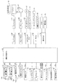
(具体的作動)
次に、本実施装置の具体的な作動について説明する。DSECUのCPU(以下、単に「CPU」と称呼される。)は、所定のタイミングになると、所定時間(演算周期)Δtが経過する毎に図10に示したセンサ物標トラッキングルーチンを、センサ物標Bn(即ち、周辺レーダセンサ16aから送信されてくるセンサ物標ID)のそれぞれに対して実行する。
(Specific operation)
Next, the specific operation of the present implementation device will be described. The CPU of the DSPE (hereinafter, simply referred to as “CPU”) performs the sensor target tracking routine shown in FIG. 10 every time a predetermined time (calculation cycle) Δt elapses at a predetermined timing. This is executed for each of the marks Bn (that is, the sensor target ID transmitted from the
従って、CPUは所定のタイミングになるとセンサ物標トラッキングルーチンのステップ1000から処理を開始してステップ1005に進み、一演算周期前に周辺レーダセンサ16aによって検出されている前回センサ物標が今回も検出できているか否かを、前述したセンサ物標IDに基づいて判定する。
Therefore, when the predetermined timing is reached, the CPU starts processing from
前回センサ物標が今回も検出できている場合、CPUはステップ1005にて「Yes」と判定して、以下に述べるとステップ1010及びステップ1015の処理を順に行った後、ステップ1095に進み、本ルーチンを一旦終了する。
ステップ1010:センサ物標の物標情報を今回検出できたセンサ物標の物標情報に更新する。
ステップ1015:CPUは、ステップ1010にて更新したセンサ物標Bnの物標情報に含まれる縦相対速度Vxobjの大きさをブロックBK1に示したルックアップテーブルMap1(以下、「マップ」とも称呼される。)に適用することにより、センサ物標Bnの存在確率の上昇率rupを演算する。更に、CPUは、センサ物標Bnの「前回の存在確率Trstpre、存在確率の上昇率rup及び演算サイクル数Cy」を(A)式に適用することにより、センサ物標Bnの今回の存在確率Trstを演算する。
Trst=Trstpre+rup×Cy・・・(A)
If the previous sensor target can be detected this time as well, the CPU determines "Yes" in
Step 1010: The target information of the sensor target is updated with the target information of the sensor target detected this time.
Step 1015: The CPU uses the lookup table Map1 (hereinafter, also referred to as “map”) in which the magnitude of the vertical relative velocity Vxobj included in the target information of the sensor target Bn updated in
Trst = Trst pre + rup x Cy ... (A)
これに対して、前回センサ物標が今回検出できていない場合、CPUはステップ1005にて「No」と判定してステップ1020に進み、センサ物標は既に外挿中ではないか否かを判定する。
On the other hand, if the previous sensor target could not be detected this time, the CPU determines "No" in
ステップ1020の処理の時点でセンサ物標Bnが既に外挿されているセンサ物標ではない場合(即ち、前回の演算時点にて検出されていたセンサ物標が、今回の演算時点にて検出されなかった場合)、CPUはステップ1020にて「Yes」と判定してステップ1025に進む。
When the sensor target Bn is not an extrapolated sensor target at the time of processing in step 1020 (that is, the sensor target detected at the time of the previous calculation is detected at the time of this calculation). If not), the CPU determines "Yes" in
CPUはステップ1025にて、センサ物標Bnの「前回の存在確率Trstpre及び前回のセンサ物標の縦相対速度Vxobj」の大きさをブロックBK2に示したマップMap2に適用することにより、最大外挿継続時間Tgを演算する。
In
その後、CPUはステップ1030に進み、前回のセンサ物標の物標情報に基づいて、今回のセンサ物標の物標情報を推定して、今回のセンサ物標の物標情報を推定した物標情報によって置換することによって更新する。即ち、CPUは、上述したセンサ物標の外挿を行う。その後、CPUはステップ1095に進み、本ルーチンを一旦終了する。 After that, the CPU proceeds to step 1030, estimates the target information of the current sensor target based on the target information of the previous sensor target, and estimates the target information of the current sensor target. Update by replacing with information. That is, the CPU extrapolates the sensor target described above. After that, the CPU proceeds to step 1095 and temporarily ends this routine.
ステップ1020の処理の時点でセンサ物標Bnが既に外挿中である場合、CPUはステップ1020にて「No」と判定してステップ1025に進み、外挿継続回数tを「+1」だけインクリメントする。
If the sensor target Bn is already extrapolated at the time of processing in
その後、CPUはステップ1035に進み、最大外挿継続時間Tgから外挿継続時間(t×Δt(一演算周期)秒)を減算することにより、残余外挿時間Tg’を算出した後ステップ1040に進み、残余外挿時間Tg’が0以下になったか否かを判定する。 After that, the CPU proceeds to step 1035, calculates the residual extrapolation time Tg'by subtracting the extrapolation duration (t × Δt (one calculation cycle) seconds) from the maximum extrapolation duration Tg, and then proceeds to step 1040. It advances and determines whether or not the residual extrapolation time Tg'is 0 or less.
残余外挿時間Tg’が0以下になっていない場合、CPUはステップ1045にて「No」と判定してステップ1030に進み、前回センサ物標の物標情報に基づいて、センサ物標の物標情報を推定して、センサ物標の物標情報を推定した物標情報に更新する。即ち、CPUは、センサ物標の外挿を行う。
If the residual extrapolation time Tg'is not 0 or less, the CPU determines "No" in
残余外挿時間Tg’が0以下になった場合、CPUはステップ1040にて「Yes」と判定してステップ1045に進み、センサ物標をロストと判定した後、ステップ1095に進んで本ルーチンを一旦終了する。
When the residual extrapolation time Tg'is 0 or less, the CPU determines "Yes" in
以上説明した本実施装置は、センサ物標の自車両に対する縦相対速度Vxobjの大きさが小さくなるほど、センサ物標の存在確率の一演算周期毎の上昇率が小さくなるように、その上昇率を求めている。更に、本実施装置は、周辺センサによって一演算周期前に検出されていた前回のセンサ物標が今回の演算周期にて検出されない場合に行う外挿処理(センサ物標の外挿)の最大外挿継続時間を、そのセンサ物標の存在確率が大きくなるほど長くなり、且つ、縦相対速度Vxobjの大きさが小さくなるほど長くなる、ように設定している。これにより、センサ物標の種類に応じた適切な最大外挿継続時間を設定することができ、以て、センサ物標の存在判定を精度良く行うことができる。その結果、車線変更支援制御を行ってよいか否かの判定を精度良く行うことができる。 The present implementation device described above sets the rate of increase so that the smaller the magnitude of the vertical relative velocity Vxobj of the sensor target with respect to the own vehicle, the smaller the rate of increase of the existence probability of the sensor target in each calculation cycle. I'm looking for. Further, the present implementation device is the maximum outside of the extrapolation process (extrapolation of the sensor target) performed when the previous sensor target detected by the peripheral sensor one calculation cycle before is not detected in the current calculation cycle. The insertion duration is set so that the larger the existence probability of the sensor target, the longer the insertion duration, and the smaller the magnitude of the vertical relative velocity Vxobj, the longer the insertion duration. As a result, an appropriate maximum extrapolation duration can be set according to the type of the sensor target, and thus the existence determination of the sensor target can be performed with high accuracy. As a result, it is possible to accurately determine whether or not lane change support control may be performed.
<変形例>
以上、本発明の実施形態について具体的に説明したが、本発明は、上述の実施形態に限定されるものではなく、本発明の技術的思想に基づく各種の変形が可能である。
<Modification example>
Although the embodiments of the present invention have been specifically described above, the present invention is not limited to the above-described embodiments, and various modifications based on the technical idea of the present invention are possible.
例えば、上述の実施形態においては、追従車間距離制御及び車線維持制御の実行中であることが、車線変更支援制御を実行するための前提となっているが、必ずしも、そのような前提は必要としない。 For example, in the above-described embodiment, it is a premise for executing the lane change support control that the following inter-vehicle distance control and the lane keeping control are being executed, but such a premise is not always necessary. do not do.
10…運転支援ECU、15…車速センサ、16a…周辺レーダセンサ、16FC…中央前方周辺センサ、16FR…右前方周辺センサ、16FL…左前方周辺センサ、16RR…右後方周辺センサ、16RL…左後方周辺センサ、16b…カメラセンサ、17…操作スイッチ、52…転舵用モータ、53…ウインカーレバースイッチ 10 ... Driving support ECU, 15 ... Vehicle speed sensor, 16a ... Peripheral radar sensor, 16FC ... Center front peripheral sensor, 16FR ... Right front peripheral sensor, 16FL ... Left front peripheral sensor, 16RR ... Right rear peripheral sensor, 16RL ... Left rear peripheral Sensor, 16b ... Camera sensor, 17 ... Operation switch, 52 ... Steering motor, 53 ... Winker lever switch
Claims (1)
前記検出されたセンサ物標の存在確率を演算する存在確率演算手段と、
検出されていた前記センサ物標が検出されなくなった場合、当該検出されていた前記センサ物標が再検出されない限り、前記検出されていたセンサ物標が検出されていたときの前記位置速度情報に基づくセンサ物標情報に基づいて前記検出されていたセンサ物標の前記センサ物標情報を推定することによって外挿されたセンサ物標を生成する外挿処理を行う外挿処理手段と、
前記存在確率及び前記検出されていたセンサ物標の縦相対速度に基づいて前記外挿処理を行う時間の最大値である最大外挿継続時間を演算する最大外挿継続時間演算手段と、
前記外挿処理を最大外挿継続時間以上行ったときに当該外挿処理を行った前記センサ物標が存在しないと判定するセンサ物標存在判定手段と、
を備え、
前記存在確率演算手段は、
前記センサ物標が検出されている場合に当該センサ物標の縦相対速度の大きさが大きくなるほど前記存在確率の上昇率が大きくなるように当該センサ物標の縦相対速度に基づいて当該存在確率の上昇率を求めるとともに、前記センサ物標が継続して検出されている時間に対応する値と前記存在確率の上昇率とに基づいて決定される前記存在確率の増大量を積算することによって前記存在確率を算出するように構成され、
前記最大外挿継続時間演算手段は、
前記存在確率が大きくなるほど前記最大外挿継続時間が長くなり、且つ、前記縦相対速度の大きさが小さくなるほど前記最大外挿継続時間が長くなるように、前記最大外挿継続時間を演算するように構成された、
物標検出装置。 Each detects the reflection point of the radar wave transmitted around the own vehicle by a three-dimensional object as a sensor target, and the sensor target including the vertical distance, the lateral position, and the relative speed of the detected sensor target with respect to the own vehicle. Multiple radar sensors that detect position and velocity information to acquire information,
Existence probability calculation means for calculating the existence probability of the detected sensor target, and
When the detected sensor target is no longer detected, the position / velocity information at the time when the detected sensor target is detected is used as long as the detected sensor target is not re-detected. An extrapolation processing means for performing extrapolation processing to generate an extrapolated sensor target by estimating the sensor target information of the detected sensor target based on the sensor target information based on the sensor.
The maximum extrapolation duration calculation means for calculating the maximum extrapolation duration, which is the maximum value of the time for performing the extrapolation process, based on the existence probability and the vertical relative velocity of the detected sensor target.
When the extrapolation process is performed for the maximum extrapolation duration or longer, the sensor target presence determination means for determining that the sensor target for which the extrapolation process has been performed does not exist, and
With
The existence probability calculation means
The existence probability on the basis of the longitudinal relative velocity of the sensor target object such that the sensor was vertical relative velocity magnitude is larger the increase rate of the existence probability of the target is increased when the sensor target object is detected The increase rate of the existence probability is obtained, and the increase amount of the existence probability determined based on the value corresponding to the time during which the sensor target is continuously detected and the increase rate of the existence probability is integrated. It is configured to calculate the probability of existence,
The maximum extrapolation duration calculation means is
The maximum extrapolation duration is calculated so that the maximum extrapolation duration becomes longer as the existence probability increases and the maximum extrapolation duration becomes longer as the magnitude of the longitudinal relative velocity decreases. Consists of,
Target detection device.
Priority Applications (1)
| Application Number | Priority Date | Filing Date | Title |
|---|---|---|---|
| JP2017114775A JP6828602B2 (en) | 2017-06-09 | 2017-06-09 | Target detection device |
Applications Claiming Priority (1)
| Application Number | Priority Date | Filing Date | Title |
|---|---|---|---|
| JP2017114775A JP6828602B2 (en) | 2017-06-09 | 2017-06-09 | Target detection device |
Publications (2)
| Publication Number | Publication Date |
|---|---|
| JP2019002689A JP2019002689A (en) | 2019-01-10 |
| JP6828602B2 true JP6828602B2 (en) | 2021-02-10 |
Family
ID=65004848
Family Applications (1)
| Application Number | Title | Priority Date | Filing Date |
|---|---|---|---|
| JP2017114775A Active JP6828602B2 (en) | 2017-06-09 | 2017-06-09 | Target detection device |
Country Status (1)
| Country | Link |
|---|---|
| JP (1) | JP6828602B2 (en) |
Families Citing this family (5)
| Publication number | Priority date | Publication date | Assignee | Title |
|---|---|---|---|---|
| JP2020179808A (en) * | 2019-04-26 | 2020-11-05 | トヨタ自動車株式会社 | Vehicle control apparatus |
| JP7263996B2 (en) * | 2019-09-19 | 2023-04-25 | 株式会社デンソー | Wall shape measuring device |
| JP7468385B2 (en) | 2021-02-01 | 2024-04-16 | トヨタ自動車株式会社 | Vehicle control device |
| JP2022169985A (en) * | 2021-04-28 | 2022-11-10 | 日立Astemo株式会社 | External environment recognition device and external environment recognition system |
| WO2023228668A1 (en) * | 2022-05-25 | 2023-11-30 | 株式会社デンソー | Surroundings monitoring device and program |
Family Cites Families (18)
| Publication number | Priority date | Publication date | Assignee | Title |
|---|---|---|---|---|
| US6873251B2 (en) * | 2002-07-16 | 2005-03-29 | Delphi Technologies, Inc. | Tracking system and method employing multiple overlapping sensors |
| JP4075624B2 (en) * | 2003-01-28 | 2008-04-16 | 株式会社デンソー | In-vehicle radar system, program |
| JP4779704B2 (en) * | 2006-02-27 | 2011-09-28 | トヨタ自動車株式会社 | Target detection apparatus and target detection method |
| JP4944535B2 (en) * | 2006-08-03 | 2012-06-06 | 本田技研工業株式会社 | Vehicle control device |
| JP4928896B2 (en) * | 2006-10-17 | 2012-05-09 | 本田技研工業株式会社 | Vehicle control device |
| JP4757146B2 (en) * | 2006-08-24 | 2011-08-24 | 本田技研工業株式会社 | Object detection device |
| JP4385064B2 (en) * | 2007-09-06 | 2009-12-16 | 本田技研工業株式会社 | Control object recognition device |
| JP2009210337A (en) * | 2008-03-03 | 2009-09-17 | Toyota Motor Corp | Radar device |
| JP5038192B2 (en) * | 2008-03-05 | 2012-10-03 | 本田技研工業株式会社 | Vehicle safety device |
| JP5093020B2 (en) * | 2008-09-18 | 2012-12-05 | トヨタ自動車株式会社 | Radar equipment |
| JP2011048641A (en) * | 2009-08-27 | 2011-03-10 | Toyota Motor Corp | Object detection device and driving support device |
| WO2011036803A1 (en) * | 2009-09-28 | 2011-03-31 | トヨタ自動車株式会社 | Object detecting device |
| JP5576727B2 (en) * | 2010-06-30 | 2014-08-20 | 富士通テン株式会社 | Signal processing device, radar device, vehicle control system, and signal processing method |
| JP5732098B2 (en) * | 2013-04-08 | 2015-06-10 | 本田技研工業株式会社 | Object detection device |
| JP6338871B2 (en) * | 2014-01-31 | 2018-06-06 | 株式会社デンソーテン | Radar apparatus, vehicle control system, and signal processing method |
| JP2015155807A (en) * | 2014-02-20 | 2015-08-27 | 富士通テン株式会社 | Radar device, vehicle control system, and signal processing method |
| JP6429486B2 (en) * | 2014-04-25 | 2018-11-28 | 株式会社デンソーテン | Radar apparatus and signal processing method |
| JP6443011B2 (en) * | 2014-12-01 | 2018-12-26 | 株式会社デンソー | Target detection device |
-
2017
- 2017-06-09 JP JP2017114775A patent/JP6828602B2/en active Active
Also Published As
| Publication number | Publication date |
|---|---|
| JP2019002689A (en) | 2019-01-10 |
Similar Documents
| Publication | Publication Date | Title |
|---|---|---|
| JP6958001B2 (en) | Lane change support device | |
| JP6816658B2 (en) | Target information acquisition device | |
| JP6828602B2 (en) | Target detection device | |
| JP6583252B2 (en) | Driving assistance device | |
| CN108238047B (en) | Driving support device | |
| CN109572672B (en) | Vehicle driving assistance device | |
| JP6897349B2 (en) | Driving support device | |
| US10864913B2 (en) | Vehicle driving support apparatus | |
| KR20200021056A (en) | Driving assistance system | |
| JP2019003234A (en) | Driving support device | |
| JP2018103941A (en) | Vehicle assisting device | |
| JP7176415B2 (en) | Pre-collision control device | |
| JP6825528B2 (en) | Vehicle driving support device | |
| JP6805970B2 (en) | Target information acquisition device | |
| JP4983564B2 (en) | Vehicle tracking device | |
| US11755022B2 (en) | Vehicle control device | |
| JP2019059252A (en) | Operation support device | |
| JP7067379B2 (en) | Vehicle lane change support device | |
| JP7091956B2 (en) | Vehicle lane change support device | |
| JP6828603B2 (en) | Target detection device | |
| JP7147648B2 (en) | Driving support device | |
| JP6361572B2 (en) | Alarm control device | |
| JP6657673B2 (en) | Vehicle control device and vehicle control method | |
| JP6082293B2 (en) | Vehicle white line recognition device | |
| JP2019059449A (en) | Vehicle driving support device |
Legal Events
| Date | Code | Title | Description |
|---|---|---|---|
| A621 | Written request for application examination |
Free format text: JAPANESE INTERMEDIATE CODE: A621 Effective date: 20190910 |
|
| A977 | Report on retrieval |
Free format text: JAPANESE INTERMEDIATE CODE: A971007 Effective date: 20201030 |
|
| A131 | Notification of reasons for refusal |
Free format text: JAPANESE INTERMEDIATE CODE: A131 Effective date: 20201104 |
|
| A521 | Request for written amendment filed |
Free format text: JAPANESE INTERMEDIATE CODE: A523 Effective date: 20201127 |
|
| TRDD | Decision of grant or rejection written | ||
| A01 | Written decision to grant a patent or to grant a registration (utility model) |
Free format text: JAPANESE INTERMEDIATE CODE: A01 Effective date: 20201222 |
|
| A61 | First payment of annual fees (during grant procedure) |
Free format text: JAPANESE INTERMEDIATE CODE: A61 Effective date: 20210104 |
|
| R151 | Written notification of patent or utility model registration |
Ref document number: 6828602 Country of ref document: JP Free format text: JAPANESE INTERMEDIATE CODE: R151 |