JP6825241B2 - Magnetic field measuring device, manufacturing method of magnetic field measuring device - Google Patents
Magnetic field measuring device, manufacturing method of magnetic field measuring device Download PDFInfo
- Publication number
- JP6825241B2 JP6825241B2 JP2016122368A JP2016122368A JP6825241B2 JP 6825241 B2 JP6825241 B2 JP 6825241B2 JP 2016122368 A JP2016122368 A JP 2016122368A JP 2016122368 A JP2016122368 A JP 2016122368A JP 6825241 B2 JP6825241 B2 JP 6825241B2
- Authority
- JP
- Japan
- Prior art keywords
- polarized light
- cell
- magnetic field
- light
- linearly polarized
- Prior art date
- Legal status (The legal status is an assumption and is not a legal conclusion. Google has not performed a legal analysis and makes no representation as to the accuracy of the status listed.)
- Active
Links
Images


Classifications
-
- G—PHYSICS
- G01—MEASURING; TESTING
- G01R—MEASURING ELECTRIC VARIABLES; MEASURING MAGNETIC VARIABLES
- G01R33/00—Arrangements or instruments for measuring magnetic variables
- G01R33/02—Measuring direction or magnitude of magnetic fields or magnetic flux
- G01R33/032—Measuring direction or magnitude of magnetic fields or magnetic flux using magneto-optic devices, e.g. Faraday or Cotton-Mouton effect
-
- G—PHYSICS
- G01—MEASURING; TESTING
- G01R—MEASURING ELECTRIC VARIABLES; MEASURING MAGNETIC VARIABLES
- G01R33/00—Arrangements or instruments for measuring magnetic variables
- G01R33/20—Arrangements or instruments for measuring magnetic variables involving magnetic resonance
- G01R33/24—Arrangements or instruments for measuring magnetic variables involving magnetic resonance for measuring direction or magnitude of magnetic fields or magnetic flux
- G01R33/243—Spatial mapping of the polarizing magnetic field
-
- G—PHYSICS
- G01—MEASURING; TESTING
- G01R—MEASURING ELECTRIC VARIABLES; MEASURING MAGNETIC VARIABLES
- G01R33/00—Arrangements or instruments for measuring magnetic variables
- G01R33/20—Arrangements or instruments for measuring magnetic variables involving magnetic resonance
- G01R33/24—Arrangements or instruments for measuring magnetic variables involving magnetic resonance for measuring direction or magnitude of magnetic fields or magnetic flux
- G01R33/26—Arrangements or instruments for measuring magnetic variables involving magnetic resonance for measuring direction or magnitude of magnetic fields or magnetic flux using optical pumping
Landscapes
- Physics & Mathematics (AREA)
- Condensed Matter Physics & Semiconductors (AREA)
- General Physics & Mathematics (AREA)
- Engineering & Computer Science (AREA)
- Power Engineering (AREA)
- Measuring Magnetic Variables (AREA)
Description
本発明は、磁場計測装置、磁場計測装置の製造方法に関する。 The present invention relates to a magnetic field measuring device and a method for manufacturing the magnetic field measuring device.
磁場計測装置として、アルカリ金属ガスや希ガスにおける原子のスピンを利用した高感度な原子磁気センサーが提案されている。 As a magnetic field measuring device, a highly sensitive magnetic magnetometer that utilizes the spin of atoms in alkali metal gas or rare gas has been proposed.
例えば、特許文献1には、プローブ光用光源と、プローブ光が伝搬する媒体と、を備え、媒体は、第1の測定位置と第2の測定位置とを有し、プローブ光の伝播経路に沿って、第1の測定位置と第2の測定位置とにおける磁場強度の差を、プローブ光の偏光回転角の差として直接測定する原子磁気センサーが開示されている。
上記特許文献1には、第1の測定位置と第2の測定位置とを同一セル内に設ける例と、別々のセル内に設ける例とが示されている。
For example,
The above-mentioned
また、例えば、特許文献2には、光源と、ガスを内部に収容したセルと、光源から射出された光を第1軸方向の偏光成分と第2軸方向の偏光成分とに分離する偏光分離部と、第2軸方向の偏光成分の光量を測定する光量測定部と、光量測定部による該光量の測定結果に基づいて、セルを透過した第1軸方向の光量により磁場を測定する磁場測定部と、を有する磁場測定装置が開示されている。
上記特許文献2には、複数のセルに対して第1軸方向の偏光成分を入射させるマルチチャンネル方式の例が示されている。
Further, for example, in Patent Document 2, the light source, the cell containing the gas inside, and the polarization separation that separates the light emitted from the light source into a polarization component in the first axis direction and a polarization component in the second axis direction. A light source measuring unit that measures the amount of light of a polarized light component in the second axis direction, and a light source measuring unit that measures the light source by the amount of light transmitted through the cell in the first axis direction based on the measurement result of the light amount by the unit and the light amount measuring unit. A magnetic field measuring device having a unit and a unit is disclosed.
The above-mentioned Patent Document 2 shows an example of a multi-channel system in which a polarization component in the first axis direction is incident on a plurality of cells.
上記特許文献1の原子磁気センサーでは、第1の測定位置を透過したプローブ光の進行方向を逆にして、第2の測定位置に入射させ透過させるとしている。これにより、第1の測定位置と第2の測定位置とにおけるプローブ光の偏光回転角をそれぞれ検出するために複数の光検出器を設ける必要がなくなることから、個々の光検出器の特性差異に基づくノイズが磁場の測定結果に混入することを防止できるとしている。
In the atomic magnetic sensor of
しかしながら、第1の測定位置と第2の測定位置とにそれぞれ決められた方向からプローブ光を入射させることは技術的に難しい。ましてや第1の測定位置と第2の測定位置とを別々のセルに設ける場合には、個々のセルに決められた方向から精度よくプローブ光を入射させることが求められる。 However, it is technically difficult to inject the probe light from the directions determined at the first measurement position and the second measurement position, respectively. Furthermore, when the first measurement position and the second measurement position are provided in separate cells, it is required that the probe light is accurately incident on each cell from a predetermined direction.
さらに、上記特許文献1における原子磁気センサーの技術思想を、上記特許文献2に示されているようなマルチチャンネル方式の磁場測定装置に当てはめようとすると、第1の測定位置と第2の測定位置とにそれぞれ複数のセルを配置する必要があり、プローブ光の入射方向に対する複数のセルの位置調整がさらに難易度を増すといった課題があった。
Further, when the technical idea of the atomic magnetic sensor in
本発明は、上述の課題の少なくとも一部を解決するためになされたものであり、以下の形態または適用例として実現することが可能である。
本発明の一態様の磁場計測装置は、直線偏光光を照射する光照射部と、アルカリ金属原子が封入され、磁場の受感方向に配置されており、照射された前記直線偏光光の偏光面の回転角を、前記磁場の影響を受けて変化させる第1セル及び第2セルと、前記直線偏光光を前記第1セルに入射させる第1の偏光光と、前記第1の偏光光と平行する第2の偏光光とに分岐する第1光分岐素子と、前記直線偏光光を前記第2セルに入射させる第3の偏光光と、前記第3の偏光光と平行する第4の偏光光とに分岐する第2光分岐素子と、を備え、前記第2の偏光光の光軸の向きと、前記第4の偏光光の光軸の向きとが同一方向となるように、前記第1セルに対する前記第2セルの位置が調整されており、該調整によって、前記第1セルに入射させる前記直線偏光光の向きと、前記第2セルに入射させる前記直線偏光光の向きと、が同一方向となるように調整されており、前記第1セル及び第2セルにおいて電気的に検出された前記直線偏光光の偏光面の回転角の変化から前記磁場を計測することを特徴とする。
The present invention has been made to solve at least a part of the above-mentioned problems, and can be realized as the following forms or application examples.
In the magnetic field measuring device of one aspect of the present invention, a light irradiation unit that irradiates linearly polarized light and an alkali metal atom are enclosed and arranged in the direction of receiving the magnetic field, and the polarized surface of the irradiated linearly polarized light. The rotation angle of the first cell and the second cell which are changed by the influence of the magnetic field, the first polarized light which causes the linearly polarized light to enter the first cell, and the parallel to the first polarized light. A first light branching element that branches into a second polarized light, a third polarized light that causes the linearly polarized light to enter the second cell, and a fourth polarized light that is parallel to the third polarized light. The first optical branching element is provided so that the direction of the optical axis of the second polarized light and the direction of the optical axis of the fourth polarized light are the same. The position of the second cell with respect to the cell is adjusted, and the direction of the linearly polarized light incident on the first cell and the direction of the linearly polarized light incident on the second cell are the same by the adjustment. The direction is adjusted, and the magnetic field is measured from a change in the rotation angle of the plane of polarization of the linearly polarized light electrically detected in the first cell and the second cell.
[適用例]本適用例に係る磁場計測装置は、直線偏光を照射する光照射部と、アルカリ金属原子が封入され、磁場の受感方向に順に配置された第1セル及び第2セルと、前記直線偏光を前記第1セルに入射させる第1の偏光と、前記第1の偏光と平行する第2の偏光とに分岐する第1光分岐素子と、前記直線偏光を前記第2セルに入射させる第3の偏光と、前記第3の偏光と平行する第4の偏光とに分岐する第2光分岐素子と、を備え、前記第2の偏光の光軸の向きと、前記第4の偏光の光軸の向きとが同一方向となるように、前記第1セルに対する前記第2セルの位置が調整されていることを特徴とする。 [Application Example] In the magnetic field measuring device according to this application example, a light irradiation unit that irradiates linearly polarized light, a first cell and a second cell in which alkali metal atoms are enclosed and arranged in order in the direction of receiving the magnetic field, and a second cell. A first optical branching element that branches the linearly polarized light into a first polarized light that causes the linearly polarized light to enter the first cell, and a second polarized light that is parallel to the first polarized light, and the linearly polarized light that enters the second cell. A second optical branching element that branches into a third polarized light to be made to be made and a fourth polarized light parallel to the third polarized light is provided, and the direction of the optical axis of the second polarized light and the fourth polarized light are provided. The position of the second cell with respect to the first cell is adjusted so that the direction of the optical axis is the same as that of the first cell.
本適用例によれば、第1光分岐素子によって分岐される第1の偏光と第2の偏光とは平行しており、第2光分岐素子によって分岐される第3の偏光と第4の偏光とは平行している。したがって、第2の偏光の光軸の向きと、第4の偏光の光軸の向きとが同一方向となるように、第1セルに対する第2セルの位置が調整されることで、第1セルと第2セルとに同じ方向から直線偏光が入射することになる。したがって、第1セル及び第2セルのそれぞれに入射する直線偏光の光軸の向きが同じになり、外部磁場の影響が適正に排除され、磁場源から発する磁場を精度よく計測可能なグラディオ型の磁場計測装置を提供することができる。 According to this application example, the first polarized light and the second polarized light branched by the first optical branching element are parallel to each other, and the third polarized light and the fourth polarized light branched by the second optical branching element are parallel to each other. Is parallel to. Therefore, by adjusting the position of the second cell with respect to the first cell so that the direction of the optical axis of the second polarization and the direction of the optical axis of the fourth polarization are the same, the first cell The linearly polarized light is incident on the second cell from the same direction. Therefore, the directions of the linearly polarized light axes incident on the first cell and the second cell are the same, the influence of the external magnetic field is properly eliminated, and the magnetic field emitted from the magnetic field source can be measured accurately. A magnetic field measuring device can be provided.
上記適用例に記載の磁場計測装置において、前記第1光分岐素子は、前記直線偏光を反射して前記第1セルに入射させて前記第1の偏光とする第1の光分岐部と、前記第1の光分岐部を透過した前記直線偏光を反射して前記第2の偏光とする第1のミラー部とを含み、前記第2光分岐素子は、前記直線偏光を反射して前記第2セルに入射させて前記第3の偏光とする第2の光分岐部と、前記第2の光分岐部を透過した前記直線偏光を反射して前記第4の偏光とする第2のミラー部とを含むとしてもよい。
この構成によれば、第1の光分岐部及び第2の光分岐部は、それぞれ入射した直線偏光を反射及び透過する機能を有している。したがって、第1の光分岐部で反射した直線偏光を第1の偏光として第1セルに入射させ、第1の光分岐部を透過した直線偏光を第1のミラー部で反射させて、第1の偏光に平行な第2の偏光とすることができる。同様に、第2の光分岐部で反射した直線偏光を第3の偏光として第2セルに入射させ、第2の光分岐部を透過した直線偏光を第2のミラー部で反射させて、第3の偏光に平行な第4の偏光とすることができる。
In the magnetic field measuring device according to the above application example, the first optical branching element has a first optical branching portion that reflects the linearly polarized light and causes it to enter the first cell to obtain the first polarized light. The second optical branching element reflects the linearly polarized light and uses the second polarized light as the second polarized light by reflecting the linearly polarized light transmitted through the first optical branching portion. A second optical branching portion that is incident on the cell to obtain the third polarized light, and a second mirror portion that reflects the linearly polarized light that has passed through the second optical branching portion to obtain the fourth polarized light. May include.
According to this configuration, the first optical branching portion and the second optical branching portion have a function of reflecting and transmitting the incident linearly polarized light, respectively. Therefore, the linearly polarized light reflected by the first optical branching portion is incident on the first cell as the first polarized light, and the linearly polarized light transmitted through the first optical branching portion is reflected by the first mirror portion to be reflected by the first mirror portion. It can be a second polarized light parallel to the polarized light of. Similarly, the linearly polarized light reflected by the second optical branching portion is incident on the second cell as the third polarized light, and the linearly polarized light transmitted through the second optical branching portion is reflected by the second mirror portion to be reflected on the second mirror portion. It can be a fourth polarized light parallel to the third polarized light.
上記適用例に記載の磁場計測装置において、前記第2の偏光の光軸の向きと、前記第4の偏光の光軸の向きとを検出可能な光軸検出部をさらに備えることが好ましい。
この構成によれば、光軸検出部を備えることにより、第1セルに入射する直線偏光である第1の偏光の光軸の向きと、第2セルに入射する同じく直線偏光である第3の偏光の光軸の向きとが同一方向であるか否かを検証可能なグラディオ型の磁場計測装置を提供できる。
In the magnetic field measuring device described in the above application example, it is preferable to further include an optical axis detecting unit capable of detecting the direction of the optical axis of the second polarized light and the direction of the optical axis of the fourth polarized light.
According to this configuration, by providing the optical axis detection unit, the direction of the optical axis of the first polarized light which is linearly polarized light incident on the first cell and the third direction which is also linearly polarized light incident on the second cell. It is possible to provide a gladio type magnetic field measuring device capable of verifying whether or not the direction of the optical axis of polarized light is the same.
上記適用例に記載の磁場計測装置において、前記第1セルに対して前記受感方向と直交する方向に配置された第3セルと、前記第2セルに対して前記受感方向と直交する方向に配置された第4セルと、を備える構成としてもよい。
この構成によれば、外部磁場の影響を適正に排除して、磁場源から発する磁場を精度よく計測可能なグラディオ型且つマルチチャンネル型の磁場計測装置を提供することができる。
In the magnetic field measuring device according to the above application example, a third cell arranged in a direction orthogonal to the sensation direction with respect to the first cell and a direction orthogonal to the sensation direction with respect to the second cell. A fourth cell arranged in the cell may be provided.
According to this configuration, it is possible to provide a gladio type and multi-channel type magnetic field measuring device capable of accurately measuring the magnetic field generated from the magnetic field source by appropriately eliminating the influence of the external magnetic field.
上記適用例の磁場計測装置において、前記光照射部は、前記第1セルと前記第3セルとに、前記直線偏光を照射する第1光照射部と、前記第2セルと前記第4セルとに、前記直線偏光を照射する第2光照射部とを含むとしてもよい。
この構成によれば、1つの光照射部からグラディオ型且つマルチチャンネル型に配置された各セルに直線偏光を照射する場合に比べて、第1光照射部及び第2光照射部のそれぞれから射出される直線偏光の光量を抑えつつ、各セルに同等な強度で直線偏光を入射させることができる。
In the magnetic field measuring device of the above application example, the light irradiation unit includes a first light irradiation unit that irradiates the first cell and the third cell with the linearly polarized light, and the second cell and the fourth cell. May include a second light irradiation unit that irradiates the linearly polarized light.
According to this configuration, as compared with the case where linearly polarized light is irradiated to each cell arranged in a gladio type and a multi-channel type from one light irradiation unit, it is emitted from each of the first light irradiation unit and the second light irradiation unit. It is possible to inject linearly polarized light into each cell with the same intensity while suppressing the amount of light of the linearly polarized light.
上記適用例に記載の磁場計測装置において、前記第1光分岐素子が配置される第1基準面と、前記第2光分岐素子が配置される第2基準面と、を有し、前記第1基準面に対する前記第2基準面の位置が調整可能となっているとしてもよい。
この構成によれば、第1基準面上に第1光分岐素子と第1セルとが配置され、第2基準面上に第2光分岐素子と第2セルとが配置されることになる。したがって、第1セルに対する第2セルの位置を個別に調整する場合に比べて、調整用の基準面を設け、第1基準面に対する第2基準面の位置を調整することで、第2の偏光の光軸の向きと、第4の偏光の光軸の向きとを同一とするように容易に調整することができる。
The magnetic field measuring device according to the above application example has a first reference plane on which the first optical branching element is arranged and a second reference plane on which the second optical branching element is arranged. The position of the second reference plane with respect to the reference plane may be adjustable.
According to this configuration, the first optical branching element and the first cell are arranged on the first reference plane, and the second optical branching element and the second cell are arranged on the second reference plane. Therefore, as compared with the case where the position of the second cell with respect to the first cell is individually adjusted, the second polarization is performed by providing a reference plane for adjustment and adjusting the position of the second reference plane with respect to the first reference plane. The direction of the optical axis of the fourth polarized light can be easily adjusted to be the same as the direction of the optical axis of the fourth polarized light.
上記適用例に記載の磁場計測装置において、磁場の前記受感方向と前記第1セル及び前記第2セルにおける前記直線偏光の入射方向とが交差しているとしてもよい。
この構成によれば、各セルに入射する直線偏光の入射方向に磁場源(計測対象)を必ずしも配置する必要がなくなることから、磁場源の配置における自由度が向上したグラディオ型の磁場計測装置を提供できる。
In the magnetic field measuring device described in the above application example, the sensitive direction of the magnetic field and the incident direction of the linearly polarized light in the first cell and the second cell may intersect.
According to this configuration, it is not always necessary to arrange the magnetic field source (measurement target) in the incident direction of the linearly polarized light incident on each cell, so that a gladio-type magnetic field measuring device having an improved degree of freedom in the arrangement of the magnetic field source can be obtained. Can be provided.
[適用例]本適用例に係る磁場計測装置の製造方法は、直線偏光を照射する光照射部と、アルカリ金属原子が封入された第1セル及び第2セルと、前記直線偏光を前記第1セルに入射させる第1の偏光と、前記第1の偏光と平行する第2の偏光とに分岐する第1光分岐素子と、前記直線偏光を前記第2セルに入射させる第3の偏光と、前記第3の偏光と平行する第4の偏光とに分岐する第2光分岐素子と、を有する磁場計測装置の製造方法であって、磁場の受感方向に前記第1セルと前記第2セルとを順に配置する配置工程と、前記第2の偏光の光軸の向きと、前記第4の偏光の光軸の向きとを検出する光軸検出工程と、前記光軸検出工程の結果に基づいて、前記第2の偏光の光軸の向きと前記第4の偏光の光軸の向きとが同一方向となるように、前記第1セルに対する前記第2セルの位置を調整する位置調整工程と、を備えたことを特徴とする。 [Application Example] In the method for manufacturing a magnetic field measuring device according to this application example, a light irradiation unit that irradiates linearly polarized light, first and second cells in which alkali metal atoms are encapsulated, and the first linearly polarized light are used. A first light-branching element that branches into a first polarized light incident on the cell, a second polarized light parallel to the first polarized light, and a third polarized light that causes the linearly polarized light to enter the second cell. A method for manufacturing a magnetic field measuring device having a second optical branching element that branches into a fourth polarized light parallel to the third polarized light, wherein the first cell and the second cell are in the direction of receiving the magnetic field. Based on the results of the arrangement step of arranging the two in order, the optical axis detection step of detecting the direction of the second polarized light axis and the direction of the fourth polarized light axis, and the result of the optical axis detection step. A position adjusting step of adjusting the position of the second cell with respect to the first cell so that the direction of the second polarized light axis and the direction of the fourth polarized light axis are the same. It is characterized by having.
本適用例によれば、位置調整工程では、光軸検出工程の結果に基づいて、第2の偏光の光軸の向きと第4の偏光の光軸の向きとが同一方向となるように、第1セルに対する第2セルの位置が調整される。第1の偏光に対して第2の偏光は平行であり、第3の偏光に対して第4の偏光が平行であることから、第1セルと第2セルとに同じ方向から直線偏光が入射することになる。したがって、第1セル及び第2セルのそれぞれに入射する直線偏光の光軸の向きが同じになり、外部磁場の影響を適正に排除可能な状態で、磁場の受感方向に第1セルと第2セルとが配置され、磁場源から発する磁場を精度よく計測可能なグラディオ型の磁場計測装置の製造方法を提供することができる。 According to this application example, in the position adjusting step, the direction of the optical axis of the second polarization and the direction of the optical axis of the fourth polarization are the same directions based on the result of the optical axis detection step. The position of the second cell with respect to the first cell is adjusted. Since the second polarized light is parallel to the first polarized light and the fourth polarized light is parallel to the third polarized light, linearly polarized light is incident on the first cell and the second cell from the same direction. Will be done. Therefore, the directions of the linearly polarized light axes incident on the first cell and the second cell are the same, and the influence of the external magnetic field can be appropriately eliminated, and the first cell and the first cell are in the magnetic field sensitive direction. It is possible to provide a method for manufacturing a gladio-type magnetic field measuring device in which two cells are arranged and the magnetic field generated from the magnetic field source can be measured accurately.
上記適用例に記載の磁場計測装置の製造方法において、前記光軸検出工程は、前記第2の偏光の光軸の向きを検出する第1工程と、前記第4の偏光の光軸の向きを検出する第2工程と、を含み、前記第2工程は、前記配置工程の後に実施され、前記第1工程で検出された前記第2の偏光の光軸の向きを基準として、前記第4の偏光の光軸の向きを検出することが好ましい。
この方法によれば、第2の偏光の光軸の向きを基準として、第4の偏光の光軸の向きが検出されるので、第1セルに対する第2セルの位置を容易に位置調整することができる。
In the method for manufacturing a magnetic field measuring device according to the above application example, the optical axis detecting step includes a first step of detecting the direction of the second polarized optical axis and the direction of the fourth polarized optical axis. The second step includes the second step of detecting, and the second step is carried out after the placement step, and the fourth step is based on the direction of the optical axis of the second polarized light detected in the first step. It is preferable to detect the direction of the optical axis of polarized light.
According to this method, the direction of the optical axis of the fourth polarized light is detected with reference to the direction of the optical axis of the second polarized light, so that the position of the second cell with respect to the first cell can be easily adjusted. Can be done.
以下、本発明を具体化した実施形態について図面に従って説明する。なお、使用する図面は、説明する部分が認識可能な状態となるように、適宜拡大または縮小して表示している。 Hereinafter, embodiments embodying the present invention will be described with reference to the drawings. The drawings to be used are enlarged or reduced as appropriate so that the parts to be explained can be recognized.
以降に説明する各実施形態は、計測対象の磁場源として例えば生体の心臓や脳などから発する微小な磁場を計測可能な光ポンピング方式の磁場計測装置を例に挙げて説明する。また、当該磁場計測装置は、磁場源と磁気センサーとの距離に起因する磁場勾配の大きさの差を利用して、磁場の計測における外部磁場の影響を排除するグラディオ型の磁気センサーの配置が導入された装置である。 Each embodiment described below will be described by taking as an example an optical pumping type magnetic field measuring device capable of measuring a minute magnetic field emitted from, for example, the heart or brain of a living body as a magnetic field source to be measured. In addition, the magnetic field measuring device uses the difference in the magnitude of the magnetic field gradient due to the distance between the magnetic field source and the magnetic sensor to eliminate the influence of the external magnetic field in the measurement of the magnetic field. It is an introduced device.
(第1実施形態)
<磁場計測装置>
本実施形態の磁場計測装置について、図1を参照して説明する。図1は第1実施形態の磁場計測装置の構成を示すブロック図である。
(First Embodiment)
<Magnetic field measuring device>
The magnetic field measuring device of the present embodiment will be described with reference to FIG. FIG. 1 is a block diagram showing a configuration of the magnetic field measuring device of the first embodiment.
図1に示すように、本実施形態の磁場計測装置100は、計測用磁気センサー11と、参照用磁気センサー12と、信号処理部105と、表示部106と、これらを統括する制御部107とを備えている。計測用磁気センサー11は、第1光照射部101Aと、第1セル102Aと、第1偏光分離部103Aと、第1受光部104Aとを含んで構成されている。参照用磁気センサー12は、第2光照射部101Bと、第2セル102Bと、第2偏光分離部103Bと、第2受光部104Bとを含んで構成されている。
As shown in FIG. 1, the magnetic
磁場計測装置100は、セルに封入されたガス状のアルカリ金属原子にポンプ光を照射することにより励起させ、励起によってスピン偏極が生じたアルカリ金属原子に直線偏光であるプローブ光を照射する。アルカリ金属原子のスピン偏極は磁場の影響を受けてアライメント方位が変化する。照射されたプローブ光は該スピン偏極のアライメント方位の影響を受けて偏光面の回転角が変化することから、上記偏光面の回転角を電気的に検出することにより、磁場の大きさ(強さ)を計測するものである。第1光照射部101A及び第2光照射部101Bのそれぞれは、上記ポンプ光及び上記プローブ光を兼ねるレーザー光Lを出力する構成となっている。つまり、本実施形態の磁場計測装置100は、光ポンピング方式及びワンビーム方式の2つの磁気センサーを備えるものである。
The magnetic
2つの磁気センサーは、それぞれ基本的に同じ構成を有していることから、計測用磁気センサー11の各構成について説明して、参照用磁気センサー12についての詳細な説明を省略する。したがって、説明に際して、第1光照射部101A及び第2光照射部101Bを総称して光照射部101と呼び、第1セル102A及び第2セル102Bを総称してセル102と呼ぶこととする。また、第1偏光分離部103A及び第2偏光分離部103Bを総称して偏光分離部103と呼び、第1受光部104A及び第2受光部104Bを総称して受光部104と呼ぶこととする。
Since each of the two magnetic sensors has basically the same configuration, each configuration of the measurement
光照射部101は、光源111と、変換部112とを有する。光源111は、レーザー光Lを発生させる装置であり、例えばレーザーダイオードおよびその駆動回路を有する。レーザー光Lの周波数は、セル102に封入されたアルカリ金属原子の超微細構造準位の遷移に対応した周波数に設定される。変換部112は、光源111から出力されたレーザー光Lの光学的な振動方向を所定の方向に変換する。つまり、変換部112は、例えば偏光板であって、レーザー光Lの偏光面の角度を所定の角度として光照射部101から射出させる。光照射部101から射出されたレーザー光Lは、例えば光ファイバー(図示省略)などの導光部材を介してセル102に照射される。なお、導光部材を介さず直接に、光照射部101からセル102にレーザー光Lを照射してもよいが、導光部材を用いると光照射部101の大きさや配置などの制約を受け難くなる。
The light irradiation unit 101 includes a
セル102の内部には、例えば、カリウム(K)、セシウム(Cs)などのアルカリ金属原子が封入される。本実施形態では、セシウム(Cs)が封入されている。セル102は、光透過性を有し、封入されるアルカリ金属と反応せず、かつアルカリ金属原子を透過しない材料、例えば石英ガラスまたはホウケイ酸ガラスなどを用いて形成される。なお、セルの材質はガラスに限らず、前述の要件を満たすものであればよく、例えば樹脂であってもよい。 Alkali metal atoms such as potassium (K) and cesium (Cs) are encapsulated inside the cell 102. In this embodiment, cesium (Cs) is encapsulated. The cell 102 is formed by using a material that has light transmittance, does not react with the enclosed alkali metal, and does not transmit the alkali metal atom, for example, quartz glass or borosilicate glass. The material of the cell is not limited to glass, and may be any material that satisfies the above-mentioned requirements, for example, resin.
セル102を透過したレーザー光Lは、偏光分離部103に入射する。なお、セル102を透過したレーザー光Lを偏光分離部103に導光部材を介して導いてもよい。 The laser beam L transmitted through the cell 102 is incident on the polarization separating unit 103. The laser light L transmitted through the cell 102 may be guided to the polarization separation unit 103 via a light guide member.
偏光分離部103は、例えば、2つの直角プリズムを接合した偏光ビームスプリッターが用いられる。2つの直角プリズムの接合面であるプリズム界面131には、例えば屈折率が異なる誘電体多層膜が形成されている。偏光分離部103は、セル102を透過した直線偏光であるレーザー光Lが、プリズム界面131に入射するように配置される。プリズム界面131に入射したレーザー光Lは、上記誘電体多層膜によってプリズム界面131の入射面と平行な第1の偏光面(直線偏光の振動面)を有する偏光L1(偏光L3)と、上記第1の偏光面に直交する第2の偏光面を有する偏光L2(偏光L4)とに分離される。偏光L1(偏光L3)は、偏光分離部103を透過して受光部104に設けられた一方の受光素子141に入射する。偏光L2(偏光L4)は、プリズム界面131(誘電体多層膜)で反射して、受光部104に設けられた他方の受光素子142に入射する。プリズム界面131の入射面とは、プリズム界面131の法線と、プリズム界面131に入射するレーザー光Lの光軸とが含まれる平面である。
As the polarization separating unit 103, for example, a polarization beam splitter in which two right-angle prisms are joined is used. For example, dielectric multilayer films having different refractive indexes are formed on the
なお、変換部112は、直線偏光であるレーザー光Lの偏光面をプリズム界面131の入射面と平行となるように変換する。言い換えれば、偏光分離部103は、プリズム界面131の入射面の向きが、変換部112によって変換されたレーザー光Lの偏光面の向きと同じになるようにセル102と受光部104との間のレーザー光Lの光軸上に配置される。これにより、セル102内に磁場が存在しないとき(セル102に磁場が印加されないとき)、セル102を透過したレーザー光Lの偏光面の角度は変化しないので、偏光分離部103に入射したレーザー光Lは、それぞれに強度が等しいレベルで偏光L1(偏光L3)と偏光L2(偏光L4)とに分離される。セル102に磁場が印加されると、磁場の影響を受けてレーザー光Lの偏光面の角度(向き)が変化することから、偏光分離部103によって分離された偏光L1(偏光L3)と偏光L2(偏光L4)とは強度に差が生ずることになる。つまり、偏光L1(偏光L3)と偏光L2(偏光L4)との強度の差からレーザー光Lの偏光面の回転角、すなわち、2つの磁気センサーのそれぞれに印加された磁場の大きさ(強さ)を求めることができる。
The
受光部104は、レーザー光Lの波長に感度を有する受光素子141及び受光素子142を有する。受光素子141,142としては、例えば、フォトダイオードなどを挙げることができる。上述したように、受光素子141は偏光L1(偏光L3)を受光し、受光した光量に応じた信号を信号処理部105に出力する。受光素子142は偏光L2(偏光L4)を受光し、受光した光量に応じた信号を同じく信号処理部105に出力する。
本実施形態における偏光分離部103及び受光部104は、プローブ光の偏光面の回転角を検出する回転角検出部の一例である。
The light receiving unit 104 includes a
The polarization separation unit 103 and the light receiving unit 104 in this embodiment are examples of rotation angle detection units that detect the rotation angle of the polarization plane of the probe light.
信号処理部105は、測定軸(本実施形態では、レーザー光Lの光軸に沿った方向)における磁場の大きさ(強さ)を算出する。上述したように、セル102を透過する前後のレーザー光Lにおける偏光面の回転角の変化量は、セル102に印加された磁場の大きさ(強さ)に依存している。信号処理部105は、まず、受光素子141および受光素子142からの信号を用いて偏光面の回転角を計算し、次に、この回転角から磁場の大きさ(強さ)を計算する。具体的には、偏光L1(偏光L3)と偏光L2(偏光L4)との光電流の差をとり、その差により磁場の大きさ(強さ)が計算される。
The
また、偏光L1(偏光L3)と偏光L2(偏光L4)との光電流の差をとる方法によれば、磁場の向きも求めることができる。例えば、光電流の差を偏光L1(偏光L3)の光電流から偏光L2(偏光L4)の光電流を引いた値として符号を考える。ここでレーザー光Lがセル102を透過する方向の磁場が存在したとき、セル102を透過した後のレーザー光Lの偏光面が回転して、偏光L1(偏光L3)の光電流が増して偏光L2(偏光L4)の光電流が減じるように偏光分離部103を設置すると、差の符号はプラス(+)となる。この偏光分離部103の設置状態で、レーザー光Lがセル102を透過する方向と逆の向きに磁場が存在したとき、セル102を透過した後のレーザー光Lの偏光面は先の回転方向とは逆方向に回転して、偏光L1(偏光L3)の光電流が減じて偏光L2(偏光L4)の光電流が増すことになり、差の符号はマイナス(−)になる。このように差の符号により磁場の向きが分かる。なお符号が、プラス(+)またはマイナス(−)のどちらにおいても、差の絶対値が、磁場の大きさ(強さ)となる。 Further, the direction of the magnetic field can also be determined by the method of taking the difference between the photocurrents of the polarized light L1 (polarized light L3) and the polarized light L2 (polarized light L4). For example, consider the sign as the difference in photocurrent as the value obtained by subtracting the photocurrent of polarized light L2 (polarized light L4) from the photocurrent of polarized light L1 (polarized light L3). Here, when there is a magnetic field in the direction in which the laser beam L passes through the cell 102, the plane of polarization of the laser beam L after passing through the cell 102 rotates, and the light current of the polarized light L1 (polarized light L3) increases to polarize it. When the polarization separating unit 103 is installed so that the light current of L2 (polarized light L4) is reduced, the sign of the difference becomes plus (+). In the installed state of the polarization separating unit 103, when a magnetic field exists in the direction opposite to the direction in which the laser beam L passes through the cell 102, the polarization plane of the laser beam L after passing through the cell 102 is in the direction of rotation. Is rotated in the opposite direction, the light current of the polarized light L1 (polarized light L3) is reduced, the light current of the polarized light L2 (polarized light L4) is increased, and the sign of the difference becomes minus (−). In this way, the direction of the magnetic field can be known from the sign of the difference. Regardless of whether the sign is plus (+) or minus (−), the absolute value of the difference is the magnitude (strength) of the magnetic field.
表示部106は、例えば、液晶ディスプレイなどの表示装置であって、信号処理部105により計算された磁場の大きさ(強さ)や向きなどを示す情報を表示する。
The
制御部107は、磁場計測装置100の各部を電気的に制御する。制御部107は、CPUなどの処理装置及びメモリーを有する。図示は省略したが、磁場計測装置100は、キーボードやタッチスクリーンなどの入力装置を備えていてもよい。
The
なお、本実施形態では、2つの磁気センサーがそれぞれ光照射部101を備える構成としたが、これに限定されるものではなく、1つの光照射部101から射出されるレーザー光Lを第1セル102Aと第2セル102Bとに導く構成としてもよい。言い換えれば、磁気センサーは、光照射部101を含まないものとして扱ってもよい。
In the present embodiment, the two magnetic sensors are each provided with the light irradiation unit 101, but the present invention is not limited to this, and the laser light L emitted from one light irradiation unit 101 is the first cell. It may be configured to lead to 102A and the
<磁場計測方法の原理>
次に、磁場計測装置100を用いた磁場計測方法の原理について、図2〜図4を用いて説明する。図2は2つの磁気センサーの配置を示す概略図、図3及び図4は2つの磁気センサーにおけるレーザー光軸と外部磁場との関係を示す図である。以降、計測用磁気センサー11と参照用磁気センサー12とを、2つの磁気センサー11,12と呼ぶこともある。
<Principle of magnetic field measurement method>
Next, the principle of the magnetic field measurement method using the magnetic
2つの磁気センサー11,12の配置を説明するにあたり、図2に示すように、互いに直交するX軸、Y軸、Z軸の直交座標を用いることとする。2つの磁気センサー11,12は、例えば、Z軸方向において、磁場源M1から近い側に第1セル102Aが配置され、第1セル102Aよりも磁場源M1から遠い側に第2セル102Bが配置される。なお、磁場源M1に対して2つの磁気センサー11,12が配置される方向は、Z軸方向に限定されるものではない。
In explaining the arrangement of the two
レーザー光LはZ軸方向に沿って第1セル102Aと第2セル102Bとにそれぞれ入射する。前述したように、第1セル102Aを透過したレーザー光Lは第1偏光分離部103Aにより偏光L1と偏光L2とに分岐され、偏光L1は受光素子141に入射し、偏光L2は受光素子142に入射する。一方、第2セル102Bを透過したレーザー光Lは第2偏光分離部103Bにより偏光L3と偏光L4とに分岐され、偏光L3は受光素子141に入射し、偏光L4は受光素子142に入射する。
The laser beam L is incident on the
図3に示すように、Z軸方向に、磁場源M1と、第1セル102Aと、第2セル102Bとがこの順に配置されており、レーザー光Lのレーザー光軸L0もまたZ軸方向に沿っているので、本実施形態の磁場計測装置100における受感方向は、矢印で示すように、Z軸方向に沿った方向となる。言い換えれば、磁場源M1と、第1セル102Aと、第2セル102Bとはこの順に受感方向に配置される。
As shown in FIG. 3, the magnetic field source M1, the
2つの磁気センサー11,12によって計測される磁場源M1の磁場の大きさは、磁場源M1から各磁気センサーまでの距離の二乗に反比例すること(ビオサバールの法則)が知られている。したがって、計測用磁気センサー11により計測される磁場源M1の磁場の大きさは、計測用磁気センサー11よりも磁場源M1から遠い位置に配置された参照用磁気センサー12により計測される磁場源M1の磁場の大きさよりも大きい。言い換えれば、参照用磁気センサー12により計測される磁場源M1の磁場の大きさは、参照用磁気センサー12よりも磁場源M1に近い位置に配置された計測用磁気センサー11により計測される磁場源M1の磁場の大きさよりも小さい。
It is known that the magnitude of the magnetic field of the magnetic field source M1 measured by the two
これに対して、例えば、図3に示すように、X軸とZ軸とにより示される座標において、地磁気などの環境磁場を含む外部磁場EMが、X軸とZ軸とに交差する斜め方向に働いているとする。Z軸方向において異なる位置に配置された2つの磁気センサー11,12には、それぞれ同じ方向及び大きさの外部磁場EMが印加される。
On the other hand, for example, as shown in FIG. 3, at the coordinates indicated by the X-axis and the Z-axis, the external magnetic field EM including the environmental magnetic field such as the geomagnetism is in the diagonal direction where the X-axis and the Z-axis intersect. Suppose you are working. External magnetic fields EM of the same direction and magnitude are applied to the two
外部磁場EMの大きさが、一般的にnT(ナノテスラ)のレベルにあるのに比べて、例えば生体における心臓や脳などの磁場源M1から発する磁場の大きさは、pT(ピコテスラ)のレベルである。したがって、磁場源M1の磁場計測は、磁場源M1から発する磁場の大きさよりも大きな外部磁場EMの影響(ノイズ)を受けることになる。 The magnitude of the external magnetic field EM is generally at the level of nT (nanotesla), whereas the magnitude of the magnetic field emitted from the magnetic field source M1 such as the heart or brain in a living body is at the level of pT (picotesla). is there. Therefore, the magnetic field measurement of the magnetic field source M1 is affected by the external magnetic field EM (noise) larger than the magnitude of the magnetic field emitted from the magnetic field source M1.
本実施形態の磁場計測装置100では、このような外部磁場EMの影響(ノイズ)を排除可能な磁場計測方法となっている。具体的には、図2に示すように、計測用磁気センサー11において、受光素子141は偏光L1を受光して電位V1を出力し、受光素子142は偏光L2を受光して電位V2を出力する。同じく、参照用磁気センサー12において、受光素子141は偏光L3を受光して電位V3を出力し、受光素子142は偏光L4を受光して電位V4を出力する。
The magnetic
信号処理部105は、例えば、3つの演算増幅部151,152,153を有している。演算増幅部151により、電位V1と電位V2との差が演算され、電位V5が出力される。演算増幅部152により、電位V3と電位V4との差が演算され、電位V6が出力される。演算増幅部153により、電位V5と電位V6との差が演算され、電位V0utが出力される。
The
電位V5は、計測用磁気センサー11が検知した、外部磁場EMのノイズを含む磁場源M1の磁場の大きさを電気的に表すものであり、電位V6は、参照用磁気センサー12が検知した、同じく外部磁場EMのノイズを含む磁場源M1の磁場の大きさを電気的に表すものである。図3に示したように、2つの磁気センサー11,12に印加される外部磁場EMの方向や大きさは同じであり、電位V5と電位V6との差を演算することで、外部磁場EMのノイズを排除することができる。また、磁場源M1から発する磁場は、磁場源M1と磁気センサーとの距離の二乗に反比例することから、参照用磁気センサー12が検知する磁場源M1の磁場の大きさは計測用磁気センサー11が検知する磁場源M1の磁場の大きさよりも格段に小さくなるので、参照用磁気センサー12が検知する磁場源M1の磁場の大きさを「ゼロ」とみなすことができる。ゆえに、電位V5と電位V6との差を演算することで、外部磁場EMのノイズを排除して、計測用磁気センサー11が検知した磁場源M1の磁場の大きさを電気的に電位Voutとして取り出すことができる。
The potential V 5 electrically represents the magnitude of the magnetic field of the magnetic field source M1 including the noise of the external magnetic field EM detected by the measurement
ところで、図4に示すように、例えば、参照用磁気センサー12の第2セル102Bにおけるレーザー光Lの入射方向、すなわちレーザー光軸L0の方向がZ軸方向からずれている場合、レーザー光Lの偏光面の回転角との関係から、参照用磁気センサー12が検知する外部磁場EMのノイズの大きさは、計測用磁気センサー11が検知する外部磁場EMのノイズの大きさと異なることになる。したがって、電位V5と電位V6との差を演算しても、外部磁場EMのノイズを適正に排除できなくなる。このような不具合は、計測用磁気センサー11の第1セル102Aにおけるレーザー光軸L0の方向がZ軸方向からずれている場合も同様に起こり得る。つまり、第1セル102A及び第2セル102Bに対するレーザー光Lの入射方向(レーザー光軸L0の向き)は、同じであることが求められる。そこで、本実施形態の磁場計測装置100は、上記のような不具合を排除可能な構成を備えており、以降、図5を参照して説明する。
By the way, as shown in FIG. 4, for example, when the incident direction of the laser light L in the
図5は第1実施形態の磁場計測装置の構成を示す概略図である。詳しくは、図5はZ軸方向と直交するY軸方向から見た磁場計測装置100の構成を示す概略図である。
FIG. 5 is a schematic view showing the configuration of the magnetic field measuring device of the first embodiment. Specifically, FIG. 5 is a schematic view showing the configuration of the magnetic
図5に示すように、磁場計測装置100は、計測用磁気センサー11の第1セル102A及び第1偏光分離部103A並びに受光素子141,142を支持する第1支持部108を有している。同じく参照用磁気センサー12の第2セル102B及び第2偏光分離部103B並びに受光素子141,142を支持する第2支持部109を有している。詳しい図示は省略するが、第1支持部108及び第2支持部109のそれぞれは、上記各部を立体的に支持可能な構造体である。第1支持部108では、構造体の底部における第1セル102A側の面が、第1基準面108aとして設定されている。同様に、第2支持部109では、構造体の底部における第2セル102B側の面が、第2基準面109aとして設定されている。
As shown in FIG. 5, the magnetic
本実施形態では、第1基準面108aの面積は第2基準面109aの面積よりも大きく、第1支持部108に第2支持部109を所定の位置で重ねたときに、Z軸方向に沿った平面視で、第1基準面108aの一部が第2基準面109aからX軸方向にはみ出すように構成されている。
In the present embodiment, the area of the
第1支持部108の第1基準面108aと第1セル102Aとの間に、偏光ビームスプリッター(PBS)121が設けられている。PBS121は、誘電体ミラー123を有している。PBS121に対してレーザー光Lは、X軸方向に沿った方向から入射する。PBS121の誘電体ミラー123に入射した直線偏光であるレーザー光Lは、直線偏光の偏光面の方向と同じ方向の偏光面を有するP偏光と、直線偏光の偏光面の方向と直交する方向の偏光面を有するS偏光とに分岐される。P偏光は誘電体ミラー123を透過し、S偏光は誘電体ミラー123により反射されてZ軸方向から第1セル102Aに入射する。
A polarization beam splitter (PBS) 121 is provided between the
第1基準面108aには、PBS121に対するレーザー光Lの入射方向において、誘電体ミラー123の後方側に反射ミラー125が設けられている。反射ミラー125は、第1基準面108aに対して45度の角度で傾斜した反射面125aを有しており、誘電体ミラー123を透過したP偏光をZ軸方向に反射させる。つまり、誘電体ミラー123で反射したS偏光の光軸と、反射ミラー125で反射したP偏光の光軸とは平行な状態となっている。
A
同様にして、第2支持部109の第2基準面109aと第2セル102Bとの間に、偏光ビームスプリッター(PBS)122が設けられている。PBS122は、誘電体ミラー124を有している。PBS122に対してレーザー光Lは、X軸方向に沿った方向から入射する。PBS122の誘電体ミラー124に入射した直線偏光であるレーザー光Lは、直線偏光の偏光面の方向と同じ方向の偏光面を有するP偏光と、直線偏光の偏光面の方向と直交する方向の偏光面を有するS偏光とに分岐される。P偏光は誘電体ミラー124を透過し、S偏光は誘電体ミラー124により反射されてZ軸方向から第2セル102Bに入射する。
Similarly, a polarization beam splitter (PBS) 122 is provided between the
第2基準面109aには、PBS122に対するレーザー光Lの入射方向において、誘電体ミラー124の後方側に反射ミラー126が設けられている。反射ミラー126は、第2基準面109aに対して45度の角度で傾斜した反射面126aを有しており、誘電体ミラー124を透過したP偏光をZ軸方向に反射させる。つまり、誘電体ミラー124で反射したS偏光の光軸と、反射ミラー126で反射したP偏光の光軸とは平行な状態となっている。
A
本実施形態では、第1基準面108aに配置された偏光ビームスプリッター121が本発明における第1の光分岐部の一例であり、同じく第1基準面108aに配置された反射ミラー125が本発明の第1のミラー部の一例である。つまり、偏光ビームスプリッター121と反射ミラー125とを含む構成が、本発明における第1光分岐素子に相当するものである。また、第2基準面109aに配置された偏光ビームスプリッター122が本発明における第2の光分岐部の一例であり、同じく第2基準面109aに配置された反射ミラー126が本発明の第2のミラー部の一例である。つまり、偏光ビームスプリッター122と反射ミラー126とを含む構成が、本発明における第2光分岐素子に相当するものである。そして、偏光ビームスプリッター121によって反射され第1セル102Aに入射するS偏光が第1の偏光に相当し、偏光ビームスプリッター121を透過して反射ミラー125で反射されたP偏光が第2の偏光に相当するものである。同様に、偏光ビームスプリッター122によって反射され第2セル102Bに入射するS偏光が第3の偏光に相当し、偏光ビームスプリッター122を透過して反射ミラー126で反射されたP偏光が第4の偏光に相当するものである。本実施形態では、図5に示すように、反射ミラー125で反射されたレーザー光L(P偏光)は平行な光束のビーム光であることからビーム光B1と呼ぶこととする。同様に、反射ミラー126で反射されたレーザー光L(P偏光)もまた平行な光束のビーム光であることからビーム光B2と呼ぶこととする。
In the present embodiment, the
なお、図5には図示していないが、第1基準面108a上において偏光ビームスプリッター121と第1セル102Aとの間には、第1セル102Aの温度を磁場計測に適した温度とするための加熱部が設けられている。加熱部は、例えば板状のセラミックヒーターであって、第1セル102Aに対するレーザー光Lの入射を阻害しないように配置されている。第2基準面109a上における偏光ビームスプリッター122と第2セル102Bとの間にも同様に加熱部が設けられている。
Although not shown in FIG. 5, in order to set the temperature of the
磁場計測装置100は、光軸検出部の一例としてのオートコリメーター170を備えている。オートコリメーター170は、計測対象物の表面で反射した反射光を検出する例えばCCDなどの受光素子を備えている。オートコリメーター170は、計測対象物の表面で反射した反射光の光軸の向きを検出することができる。本実施形態では、オートコリメーター170は、Z軸方向において第1基準面108aに配置された反射ミラー125と第2基準面109aに配置された反射ミラー126とをそれぞれ臨むことが可能となるように、第1支持部108及び第2支持部109に対して少なくともX軸方向に相対的に移動可能な状態で設けられている。
The magnetic
図5に示すように、本実施形態の磁場計測装置100では、オートコリメーター170を用いて、反射ミラー125で反射したビーム光B1の光軸の向きと、反射ミラー126で反射したビーム光B2の光軸の向きとを検出する。磁場計測装置100は、第1セル102Aに対する第2セル102Bの位置、言い換えれば、第1基準面108aを含む第1支持部108に対する第2基準面109aを含む第2支持部109の位置を調整可能な位置調整機構を備えている。位置調整機構により、オートコリメーター170の検出結果に基づいて、第1支持部108に対する第2支持部109の位置を調整することができる。制御部107がオートコリメーター170の検出結果を参照して、第1支持部108に対する第2支持部109の位置を自動的に調整できるように、位置調整機構を構成してもよいし、オートコリメーター170の検出結果を表示部106に表示し、作業者が表示を確認して第1支持部108に対する第2支持部109の位置を調整できるように、位置調整機構を構成してもよい。
As shown in FIG. 5, in the magnetic
図5では、上記位置調整機構について具体的に図示をしていないが、第1支持部108に対する第2支持部109の位置を、X軸方向、Y軸方向、Z軸方向において調整可能であると共に、X軸、Y軸、Z軸の各軸に対しての傾きを調整可能な機構であれば、どのような機構であってもよいが、磁場計測に影響を及ぼすような素材を位置調整機構に適用しないことが好ましい。
Although the position adjusting mechanism is not specifically shown in FIG. 5, the position of the
本実施形態の磁場計測装置100の製造方法は、第1セル102Aに対する第2セル102Bの位置を調整する、言い換えれば第1支持部108に対する第2支持部109の位置を調整する位置調整工程を含むものである。以降、磁場計測装置100の製造方法について説明する。
The manufacturing method of the magnetic
<磁場計測装置の製造方法>
本実施形態の磁場計測装置100の製造方法は、磁場の受感方向に第1セル102Aと第2セル102Bとを順に配置する配置工程(ステップS1)と、反射ミラー125で反射したビーム光B1の光軸の向きと、反射ミラー126で反射したビーム光B2の光軸の向きとを検出する光軸検出工程(ステップS2)と、光軸検出工程の結果に基づいて、第1支持部108に対する第2支持部109の位置を調整する位置調整工程(ステップS3)と、を備えている。以降、図5及び図6を参照して説明する。
<Manufacturing method of magnetic field measuring device>
The method for manufacturing the magnetic
本実施形態におけるステップS1の配置工程は、具体的には、図5に示すように、計測用磁気センサー11が組み込まれた第1支持部108に、参照用磁気センサー12が組み込まれた第2支持部109を、Z軸方向に重ねて配置する工程である。この時点では、第1支持部108に対して第2支持部109が所定の位置で仮止めされた状態となっている。そして、ステップS2へ進む。
Specifically, in the arrangement step of step S1 in the present embodiment, as shown in FIG. 5, a
ステップS2の光軸検出工程は、ビーム光B1の光軸の向きを検出する第1工程と、ビーム光B2の光軸の向きを検出する第2工程と、を含んでいる。 The optical axis detection step of step S2 includes a first step of detecting the direction of the optical axis of the beam light B1 and a second step of detecting the direction of the optical axis of the beam light B2.
図6は、ビーム光B1の光軸の向きの検出結果の一例と、ビーム光B2の光軸の向きの検出結果の一例とを示す図である。図6に示した同心円は、同心円の中心を基準点として検出された光軸の座標を示すものである。同心円の中心である基準点は、この場合、磁場計測装置100の設計上、Z軸方向からオートコリメーター170に入射した光の光軸の座標を示すものである。つまり、オートコリメーター170で検出された光軸の座標は、基準点に対する光軸の向きとしての光軸の方向及び角度を示すものである。
FIG. 6 is a diagram showing an example of a detection result of the direction of the optical axis of the beam light B1 and an example of a detection result of the direction of the optical axis of the beam light B2. The concentric circles shown in FIG. 6 indicate the coordinates of the optical axis detected with the center of the concentric circles as a reference point. In this case, the reference point, which is the center of the concentric circles, indicates the coordinates of the optical axis of the light incident on the autocollimator 170 from the Z-axis direction due to the design of the magnetic
ステップS2の第1工程では、図5に示すように、オートコリメーター170により、反射ミラー125で反射した第2の偏光としてのビーム光B1の光軸の向きを検出する。図6には、検出されたビーム光B1の光軸の向き(座標)を「×」印として示している。この時点で、図6に示すように、ビーム光B1の光軸の向き(座標)が基準点から大きくずれていた場合には、ビーム光B1の光軸の向き(座標)と基準点とが合致するように、第1支持部108における計測用磁気センサー11の位置が調整される。具体的には、第1基準面108aに対する偏光ビームスプリッター121、第1セル102A、第1偏光分離部103A、第1受光部104A(受光素子141,142)の相対的な位置の調整がなされる。このような、第1支持部108側の調整が終了するまで、ビーム光B1の光軸の向き(座標)の検出は繰り返し行われる。第1支持部108側の調整が終了した時点で、調整後のビーム光B1の光軸の向き(座標)がオートコリメーター170における基準点として再設定される。なお、ビーム光B1の光軸の向き(座標)と基準点とは厳密に合致する必要はなく、互いの相対的な位置関係が予め定められた範囲内ならばほぼ合致したとして扱ってもよい。
In the first step of step S2, as shown in FIG. 5, the
ステップS2の第2工程では、図5に示すように、オートコリメーター170をX軸方向に相対的に移動させ、ビーム光B1の光軸の向き(座標)を基準点として再設定されたオートコリメーター170により、反射ミラー126で反射したビーム光B2の光軸の向き(座標)を検出する。図6には、ビーム光B2の光軸の向き(座標)を「×」印として示している。そして、ステップS3へ進む。
In the second step of step S2, as shown in FIG. 5, the
ステップS3の位置調整工程では、ステップS2の第2工程で、図6に示すように、ビーム光B2の光軸の向き(座標)が再設定された基準点からずれていた場合には、ビーム光B2の光軸の向き(座標)と基準点とが合致するように、第1支持部108に対する第2支持部109の位置が前述した位置調整機構を用いて調整される。つまり、ビーム光B1の光軸の向きと、ビーム光B2の光軸の向きとが同一方向となるように、第1支持部108に対する第2支持部109の位置を調整する。このような、第2支持部109側の調整が終了するまで、ビーム光B2の光軸の向き(座標)の検出は繰り返し行われる。
In the position adjusting step of step S3, when the direction (coordinates) of the optical axis of the beam light B2 deviates from the reset reference point in the second step of step S2, as shown in FIG. The position of the
ビーム光B1の光軸の向きは、第1セル102Aにおけるレーザー光軸L0の向きと基本的に同一方向である。また、ビーム光B2の光軸の向きは、第2セル102Bにおけるレーザー光軸L0の向きと基本的に同一方向である。したがって、位置調整工程で、ビーム光B1の光軸の向きを基準(基準点)として、基準点とビーム光B2の光軸の向きとが合致するように調整すれば、第1セル102Aにおけるレーザー光軸L0の向きと第2セル102Bにおけるレーザー光軸L0の向きとを同一方向とすることができる。
The direction of the optical axis of the beam light B1 is basically the same as the direction of the laser optical axis L 0 in the
なお、第1セル102Aにおけるレーザー光軸L0の向きと第2セル102Bにおけるレーザー光軸L0の向きとの差を光軸角度精度として捉えた場合、オートコリメーター170における光軸角度測定分解能は、上記光軸角度精度と同等、もしくは上記光軸角度精度よりも小さいことが求められる。
In the case where capturing the difference between the orientation of the laser optical axis L 0 of the orientation and the
上記第1実施形態の磁場計測装置100とその製造方法によれば、以下の効果が得られる。
(1)磁場計測装置100は、計測用磁気センサー11が組み込まれる第1支持部108と、参照用磁気センサー12が組み込まれる第2支持部109とを有している。また、受感方向(Z軸方向)において、第1支持部108の第1基準面108aに設けられた反射ミラー125と、第2支持部109の第2基準面109aに設けられた反射ミラー126とをそれぞれ臨むことが可能な光軸検出部としてのオートコリメーター170を備えている。また、第1支持部108に対する第2支持部109の位置を調整可能な位置調整機構を備えている。磁場計測装置100の製造方法において、光軸検出工程(ステップS2)では、オートコリメーター170により、反射ミラー125で反射した第2の偏光であるビーム光B1の光軸の向きと、反射ミラー126で反射された第4の偏光であるビーム光B2の光軸の向きとが検出される。位置調整工程(ステップS3)では、オートコリメーター170の検出結果に基づいて、位置調整機構により、ビーム光B1の光軸の向きとビーム光B2の光軸の向きとが合致するように、すなわち、第1セル102A及び第2セル102Bにおけるレーザー光軸L0の向き(レーザー光Lの入射方向)が同一方向となるように、第1支持部108に対する第2支持部109の位置が調整される。したがって、受感方向に配置された、計測用磁気センサー11と参照用磁気センサー12とにおいて、外部磁場EMのノイズが同水準で検知されるため、信号処理部105により第1受光部104Aの出力と第2受光部104Bの出力との差を演算することで、外部磁場EMの影響(ノイズ)を適正に排除することができる。すなわち、外部磁場EMの影響(ノイズ)を適正に排除して、計測用磁気センサー11により磁場源M1の磁場を精度よく計測可能なグラディオ型の磁場計測装置100及びその製造方法を提供することができる。
According to the magnetic
(1) The magnetic
(2)光軸検出工程(ステップS2)は、反射ミラー125で反射された第2の偏光であるビーム光B1の光軸の向きを検出する第1工程と、反射ミラー126で反射された第4の偏光であるビーム光B2の光軸の向きを検出する第2工程とを有している。第2工程は、計測用磁気センサー11が組み込まれた第1支持部108と、参照用磁気センサー12が組み込まれた第2支持部109とを受感方向に重ねて配置する配置工程(ステップS1)の後に実施され、第1工程で検出されたビーム光B1の光軸の向きを基準として、ビーム光B2の光軸の向きを検出する。したがって、位置調整工程では、第2工程の検出結果により、第1支持部108に対する第2支持部109の位置、つまり第1セル102Aに対する第2セル102Bの位置を容易に位置調整することができる。すなわち、2つの磁気センサー11,12のそれぞれにおいて、レーザー光軸L0の向きを個別に調整してから配置工程を実施する場合に比べて、第1セル102A及び第2セル102Bにおけるレーザー光軸L0の向きを容易に調整することができる。
(2) The optical axis detection step (step S2) includes a first step of detecting the direction of the optical axis of the beam light B1 which is the second polarized light reflected by the
次に、他の実施形態の磁場計測装置について、図面を参照して説明する。 Next, the magnetic field measuring device of another embodiment will be described with reference to the drawings.
(第2実施形態)
図7は第2実施形態の磁場計測装置の構成を示す概略図である。詳しくは、図7は上記第1実施形態における図5に対応するものである。第2実施形態の磁場計測装置において、上記第1実施形態の磁場計測装置100と同じ構成には同じ符号を付して詳細な説明は省略する。また、第2実施形態の磁場計測装置もまた、基本的に上記第1実施形態の図1及び図2に示したグラディオ型の構成を有するものである。
(Second Embodiment)
FIG. 7 is a schematic view showing the configuration of the magnetic field measuring device of the second embodiment. Specifically, FIG. 7 corresponds to FIG. 5 in the first embodiment. In the magnetic field measuring device of the second embodiment, the same components as those of the magnetic
図7に示すように、本実施形態の磁場計測装置200は、計測用磁気センサー11が組み込まれた第1支持部108と、参照用磁気センサー12が組み込まれた第2支持部109とを有している。受感方向(Z軸方向)に第1支持部108と第2支持部109とが重ねて配置されている。構造体である第1支持部108の底部における第1セル102A側の面が、第1基準面108aとして設定されている。同様に、構造体である第2支持部109の底部における第2セル102B側の面が、第2基準面109aとして設定されている。
As shown in FIG. 7, the magnetic
第1基準面108aと第1セル102Aとの間には、第1光照射部101Aから射出されたレーザー光Lを第1セル102AにZ軸方向から入射させる第1光分岐素子としての無偏光ビームスプリッター(NPBS)221が配置されている。NPBS221は、入射したレーザー光LのP偏光成分のうち一部を透過し、残りを反射して第1セル102Aに入射させる誘電体ミラー223と、誘電体ミラー223を透過したP偏光成分をZ軸方向に反射させる誘電体ミラー225とを有している。
Between the
同様に、第2基準面109aと第2セル102Bとの間には、第2光照射部101Bから射出されたレーザー光Lを第2セル102BにZ軸方向から入射させる第2光分岐素子としての無偏光ビームスプリッター(NPBS)222が配置されている。NPBS222は、入射したレーザー光LのP偏光成分のうち一部を透過し、残りを反射して第2セル102Bに入射させる誘電体ミラー224と、誘電体ミラー224を透過したP偏光をZ軸方向に反射させる誘電体ミラー226とを有している。
Similarly, between the
NPBS221は、第1基準面108aのほぼ全面に亘って設けられている。同じく、NPBS222は、第2基準面109aのほぼ全面に亘って設けられている。Z軸方向に沿った平面視におけるNPBS221の面積は、NPBS222の面積よりも大きい。
The NPBS221 is provided over almost the entire surface of the
受感方向(Z軸方向)において、NPBS221の誘電体ミラー225と、NPBS222の誘電体ミラー226とに臨むことが可能となるようにオートコリメーター170が設けられている。
An
本実施形態の磁場計測装置200の製造方法は、基本的に上記第1実施形態の磁場計測装置100の製造方法と同じであるが、光軸検出工程では、オートコリメーター170は第1基準面108aに設けられたNPBS221の誘電体ミラー225で反射したビーム光B1の光軸の向きを検出する。同じく、オートコリメーター170は第2基準面109aに設けられたNPBS222の誘電体ミラー226で反射したビーム光B2の光軸の向きを検出する。
The manufacturing method of the magnetic
このような第2実施形態の磁場計測装置200とその製造方法によれば、上記第1実施形態の磁場計測装置100に比べて、反射ミラー125,126を別途設ける必要がないので、装置の構成を簡略化して上記第1実施形態における効果と同等の効果を得ることができる。
According to the magnetic
(第3実施形態)
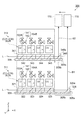
図8は第3実施形態の磁場計測装置におけるセルの配置を示す概略平面図、図9は第3実施形態の磁場計測装置の構成を示す概略図である。詳しくは、図9は上記第1実施形態における図5に対応するものである。第3実施形態の磁場計測装置において、上記第1実施形態の磁場計測装置100と同じ構成には同じ符号を付して詳細な説明は省略する。第3実施形態の磁場計測装置もまた、基本的に上記第1実施形態の図1及び図2に示したグラディオ型の構成を有するものであるが、計測用磁気センサー及び参照用磁気センサーのそれぞれをマルチチャンネル型とした磁場計測装置である。
(Third Embodiment)
FIG. 8 is a schematic plan view showing the arrangement of cells in the magnetic field measuring device of the third embodiment, and FIG. 9 is a schematic view showing the configuration of the magnetic field measuring device of the third embodiment. Specifically, FIG. 9 corresponds to FIG. 5 in the first embodiment. In the magnetic field measuring device of the third embodiment, the same components as those of the magnetic
図8は、本実施形態の磁場計測装置300におけるセルの配置を示すものであって、詳しくは、受感方向(Z軸方向)に沿った平面視におけるセルの配置を示すものである。
図8に示すように、本実施形態の磁場計測装置300は、計測用磁気センサー311を有する。計測用磁気センサー311は、複数のセルからなるセルアレイ302Aを含んで構成されたマルチチャンネル型となっている。磁場計測装置300は、セルアレイ302Aの各セルにレーザー光Lを入射させる第1光学素子321を有している。また、磁場計測装置300は、計測用磁気センサー311が組み込まれる第1支持部308を有している。
FIG. 8 shows the arrangement of cells in the magnetic
As shown in FIG. 8, the magnetic
セルアレイ302Aは、X軸方向とY軸方向とにマトリックス状に配置された、例えばセルC1〜セルC16までの16個のセルを含むものである。なお、セルの数はこれに限定されるものではない。また、図8では、X軸方向とY軸方向とに隙間を置いて複数のセルを配置しているが、隣り合うセルを密着させた状態で配置してもよい。
The
第1光学素子321は、セルアレイ302AのY軸方向に配列する4つのセルを単位としたセル群のそれぞれにレーザー光Lを導く複数の無偏光ビームスプリッター(NPBS)を備えている。具体的には、第1光学素子321は、X軸方向に並んで配置された4つの無偏光ビームスプリッター(NPBS)322,323,324,325と、4つのNPBS322,323,324,325のそれぞれに対応してY軸方向に並んで配置された4つのNPBS331,332,333,334とを備えている。
The first
4つのNPBS322,323,324,325は、X軸方向から入射したレーザー光LのP偏光成分の一部を透過し、残りを反射する。具体的には、4つのNPBS322,323,324,325におけるP偏光成分の反射率Rと透過率Tとの割合は、以下の表1に示す通りである。
The four

4つのNPBS331,332,333,334は、Y軸方向から入射したレーザー光L(P偏光)をY軸方向に配列した4つのセルのそれぞれに同じ強度で入射させる。具体的には、4つのNPBS331,332,333,334におけるP偏光成分の反射率Rと透過率Tとの割合は、例えば、以下の表2に示す通りである。
The four
レーザー光Lは、X軸方向に沿って第1光学素子321のNPBS322に入射する。NPBS322に入射したレーザー光LのP偏光成分うち一部はNPBS322を透過し、NPBS322で反射したP偏光成分は、NPBS331,332,333,334に入射してY軸方向に並ぶセルC1〜セルC4に導かれる。セルC1〜セルC4に導かれたP偏光は、セルC1〜セルC4のそれぞれにZ軸方向から入射して透過する。
The laser beam L is incident on the
NPBS322を透過しNPBS323に入射したP偏光成分の一部はNPBS323を透過し、NPBS323で反射したP偏光成分は、NPBS331,332,333,334に入射してY軸方向に並ぶセルC5〜セルC8に導かれる。セルC5〜セルC8に導かれたP偏光は、セルC5〜セルC8のそれぞれにZ軸方向から入射して透過する。
A part of the P-polarized light component transmitted through
NPBS323を透過しNPBS324に入射したP偏光成分の一部はNPBS324を透過し、NPBS324で反射したP偏光成分は、NPBS331,332,333,334に入射してY軸方向に並ぶセルC9〜セルC12に導かれる。セルC9〜セルC12に導かれたP偏光は、セルC9〜セルC12のそれぞれにZ軸方向から入射して透過する。 A part of the P-polarized light component transmitted through NPBS323 and incident on NPBS324 transmitted through NPBS324, and the P-polarized light component reflected by NPBS324 was incident on NPBS331,332,333,334 and lined up in the Y-axis direction, cells C9 to C12. Guided to. The P-polarized light guided to the cells C9 to C12 is incident on and transmitted to each of the cells C9 to C12 from the Z-axis direction.
NPBS324を透過しNPBS325に入射したP偏光成分のうち一部はNPBS325を透過し、NPBS325で反射したP偏光成分は、NPBS331,332,333,334に入射してY軸方向に並ぶセルC13〜セルC16に導かれる。セルC13〜セルC16に導かれたP偏光は、セルC13〜セルC16のそれぞれにZ軸方向から入射して透過する。 Some of the P-polarized light components transmitted through NPBS324 and incident on NPBS325 are transmitted through NPBS325, and the P-polarized light components reflected by NPBS325 are incident on NPBS331,332,333,334 and are arranged in the Y-axis direction. Guided by C16. The P-polarized light guided to the cells C13 to C16 is incident on and transmitted to each of the cells C13 to C16 from the Z-axis direction.
第1光学素子321に対してレーザー光Lが入射するX軸方向において、NPBS325の後方側に反射ミラー326が配置されている。NPBS325を透過したP偏光成分は、反射ミラー326によってZ軸方向に反射される。本実施形態では、上記表1に示すように、NPBS325に入射した光のうち5%が反射ミラー326で反射される構成となっている。
A
図8では、セルC1〜セルC16をZ軸方向から入射して透過するレーザー光L(P偏光)の光軸の位置を「黒い点」で示している。また、反射ミラー326で反射されるレーザー光L(P偏光)の光軸の位置もまた「黒い点」で示している。なお、マトリックス状に配置された複数のセルに対してレーザー光Lが導かれる方向は、X軸方向であることに限定されず、Y軸方向であってもよい。
In FIG. 8, the position of the optical axis of the laser beam L (P-polarized light) that is incident and transmitted through the cells C1 to C16 from the Z-axis direction is indicated by a “black dot”. The position of the optical axis of the laser beam L (P-polarized light) reflected by the
第1支持部308は、Z軸方向に沿った平面視で、セルC1〜セルC16に対応して設けられた第1光学素子321に重なる部分と、当該部分からX軸方向に突出した突出部308bとを有している。本実施形態では、突出部308bのセル側の面が第1基準面308aに設定されている。
The
本実施形態の磁場計測装置300は、計測用磁気センサー311に対応した参照用磁気センサーを有し、参照用磁気センサーもまた計測用磁気センサー311と同様なマルチチャンネル型の構成を有するものである。以降、図9を参照して、磁場計測装置300の構成について説明する。
The magnetic
図9に示すように、磁場計測装置300は、受感方向(Z軸方向)に配置された、計測用磁気センサー311と、参照用磁気センサー312とを有している。計測用磁気センサー311は、セルC1〜セルC16からなるセルアレイ302Aと、セルごとに設けられた第1偏光分離部103Aと、受光素子141,142(第1受光部104A)とを有している。参照用磁気センサー312は、16個のセルC21〜セルC36からなるセルアレイ302Bと、セルごとに設けられた第2偏光分離部103Bと、受光素子141,142(第2受光部104B)とを有している。
As shown in FIG. 9, the magnetic
また、磁場計測装置300は、計測用磁気センサー311が組み込まれる第1支持部308と、参照用磁気センサー312が組み込まれる第2支持部309とを有している。構造体としての第1支持部308の底部とセルアレイ302Aとの間に、セルアレイ302Aの各セルにレーザー光LをZ軸方向から入射させる第1光学素子321が設けられている。
Further, the magnetic
構造体としての第2支持部309の底部とセルアレイ302Bとの間に、セルアレイ302Bの各セルにレーザー光LをZ軸方向から入射させる第2光学素子341が設けられている。第2光学素子341の構成もまた、第1光学素子321と同様であって、各セルにレーザー光Lを導くために、X軸方向に配列した無偏光ビームスプリッター(NPBS)342,343,344,345と、Y軸方向に並んで配置された4つの無偏光ビームスプリッター(NPBS)とを有している。無偏光ビームスプリッター(NPBS)342,343,344,345におけるP偏光成分の反射率Rと透過率Tとの割合は、先に示した表1のNPBS322,323,324,325の内容と同じである。
Between the bottom of the
第2光学素子341における上述した各NPBSは、セルC21〜セルC36を透過するレーザー光Lの強度が、セルC21〜セルC36ごとにほぼ同等となるように、各NPBSにおけるレーザー光LのP偏光成分における反射率Rと透過率Tとが設定されている。具体的には、4つのNPBSにおけるP偏光成分の反射率Rと透過率Tとの割合は、先に示した表2のNPBS331,332,333,334の内容と同じである。
Each of the above-mentioned NPBSs in the second
第2光学素子341に対してレーザー光Lが入射するX軸方向において、NPBS345の後方側に反射ミラー346が配置されている。NPBS345を透過したP偏光は、反射ミラー346によってZ軸方向に反射される。本実施形態では、上記表1に示されたNPBS325と同様に、NPBS345に入射した光のうち5%が反射ミラー346で反射される構成となっている。
A
計測用磁気センサー311及び参照用磁気センサー312がマルチチャンネル型である場合、1つの光照射部110から発したレーザー光Lを2組のセルアレイ302A,302Bに導くよりも、計測用磁気センサー311用の第1光照射部101Aと、参照用磁気センサー312用の第2光照射部101Bとを備えることが好ましい。1つの光照射部110を用いる場合に比べて、光源111から射出されるレーザー光Lの強度を抑えて、各セルを透過するレーザー光Lの強度をほぼ同等とし易い。
When the measurement
本実施形態の磁場計測装置300において、例えば、セルC1を本発明における第1セルとすれば、セルC2は本発明における第3セルに相当するものである。同様に、セルC21を本発明における第2セルとすれば、セルC22は本発明における第4セルに相当するものである。また、第1の光分岐部としての第1光学素子321と、第1のミラー部としての反射ミラー326とを含む構成が、本発明の第1光分岐素子に相当し、第2の光分岐部としての第2光学素子341と、第2のミラー部としての反射ミラー346とを含む構成が、本発明の第2光分岐素子に相当するものである。
In the magnetic
計測用磁気センサー311、第1光学素子321、反射ミラー326が組み込まれた第1支持部308に、参照用磁気センサー312、第2光学素子341、反射ミラー346が組み込まれた第2支持部309が、受感方向(Z軸方向)に重ねられている。
The
Z軸方向に沿った平面視で、第2支持部309は、第1支持部308における突出部308bと重なる位置に突出部309bを有している。突出部308bのセルアレイ302A側の面が第1基準面308aとして設定され、突出部309bのセルアレイ302B側の面が第2基準面309aとして設定されている。X軸方向において、突出部308bの端部に反射ミラー326が配置され、同じく、突出部309bの端部に反射ミラー346が配置されている。
In a plan view along the Z-axis direction, the
なお、図9には図示していないが、第1基準面308a上において第1光学素子321とセルアレイ302Aとの間には、セルアレイ302Aの各セルの温度を磁場計測に適した温度とするための加熱部が設けられている。加熱部は、例えば板状のセラミックヒーターであって、セルアレイ302Aの各セルに対するレーザー光Lの入射を阻害しないように配置されている。第2基準面309a上における第2光学素子341とセルアレイ302Bとの間にも同様に加熱部が設けられている。
Although not shown in FIG. 9, the temperature of each cell of the
受感方向(Z軸方向)において、第1基準面308aに設けられた反射ミラー326と第2基準面309aに設けられた反射ミラー346とにそれぞれ臨むことが可能となるようにオートコリメーター170が設けられている。オートコリメーター170は反射ミラー326の反射面326aで反射した第2の偏光であるビーム光B1の光軸の向きを検出することができる。同じく、オートコリメーター170を第1支持部308及び第2支持部309に対してX軸方向に相対的に移動させることにより、オートコリメーター170は反射ミラー346の反射面346aで反射した第4の偏光であるビーム光B2の光軸の向きを検出することができる。
The
磁場計測装置300は、第1支持部308に対する第2支持部309の位置を調整可能な位置調整機構を有している。磁場計測装置300は、オートコリメーター170により検出されたビーム光B1の光軸の向きと、ビーム光B2の光軸の向きとが同一方向となるように、位置調整機構により、第1支持部308に対する第2支持部309の位置、すなわちセルアレイ302Aに対するセルアレイ302Bの位置が調整されている。
The magnetic
磁場計測装置300の製造方法は、上記第1実施形態の磁場計測装置100の製造方法と、基本的に同様であり、磁場の受感方向に、セルアレイ302Aが組み込まれた第1支持部308と、セルアレイ302Bが組み込まれた第2支持部309とを順に配置する配置工程と、第2の偏光としてのビーム光B1の光軸の向きと、第4の偏光としてのビーム光B2の光軸の向きとを検出する光軸検出工程と、光軸検出工程の結果に基づいて、ビーム光B1の光軸の向きと、ビーム光B2の光軸の向きとが同一方向となるように、第1支持部308に対する第2支持部309の位置を調整する位置調整工程と、を備えている。
The manufacturing method of the magnetic
上記光軸検出工程は、反射ミラー326で反射したビーム光B1の光軸の向きを検出する第1工程と、反射ミラー346で反射したビーム光B2の光軸の向きを検出する第2工程とを有している。第2工程は、上記配置工程の後に実施され、第1工程で検出されたビーム光B1の光軸の向きを基準として、ビーム光B2の光軸の向きを検出する。
The optical axis detection step includes a first step of detecting the direction of the optical axis of the beam light B1 reflected by the
上記第3実施形態の磁場計測装置300とその製造方法によれば、グラディオ型、且つマルチチャンネル型に配置された各セルに対して同じ方向から直線偏光であるレーザー光Lが入射する。言い換えれば、各セルにおけるレーザー光軸L0の向きが同一方向となり、外部磁場EMの影響(ノイズ)を適正に排除して、計測用磁気センサー311により磁場源M1の磁場を精度よく計測可能なグラディオ型、且つマルチチャンネル型の磁場計測装置300及びその製造方法を提供することができる。磁場計測装置300はマルチチャンネル型であることから、上記第1実施形態の磁場計測装置100及び第2実施形態の磁場計測装置200に比べて、広範囲に亘って磁場源M1の磁場を計測することができる。
According to the magnetic
また、上記位置調整工程では、第2工程の検出結果により、第1支持部308に対する第2支持部309の位置を容易に位置調整することができる。すなわち、2つの磁気センサー311,312のそれぞれにおいて、レーザー光軸L0の向きを個別に調整してから配置工程を実施する場合に比べて、セルアレイ302A及びセルアレイ302Bにおけるレーザー光軸L0の向きを容易に調整することができる。言い換えれば、マルチチャンネル型であっても、プローブ光として機能するレーザー光Lのレーザー光軸L0の向きを容易に調整することができる。
Further, in the position adjusting step, the position of the
本発明は、上記した実施形態に限られるものではなく、請求の範囲および明細書全体から読み取れる発明の要旨あるいは思想に反しない範囲で適宜変更可能であり、そのような変更を伴う磁気計測装置および該磁気計測装置の製造方法もまた本発明の技術的範囲に含まれるものである。上記実施形態以外にも様々な変形例が考えられる。以下、変形例を挙げて説明する。 The present invention is not limited to the above-described embodiment, and can be appropriately modified within the scope of claims and within a range not contrary to the gist or idea of the invention that can be read from the entire specification, and a magnetic measuring device and a magnetic measuring device accompanied by such a modification. The method for manufacturing the magnetic measuring device is also included in the technical scope of the present invention. Various modifications other than the above embodiment can be considered. Hereinafter, a modified example will be described.
(変形例1)プローブ光として機能するレーザー光Lのレーザー光軸L0の向きと、受感方向とは必ずしも一致していなくてもよい。図10は変形例のレーザー光軸の向きと外部磁場との関係を示す概略図、図11は変形例のレーザー光軸の向きの調整方法を示す概略図である。詳しくは、図10及び図11は、上記第1実施形態の磁場計測装置100とその製造方法を踏まえたものである。
(Modification 1) The direction of the laser optical axis L 0 of the laser beam L functioning as the probe light and the sensation direction do not necessarily have to match. FIG. 10 is a schematic view showing the relationship between the direction of the laser optical axis of the modified example and the external magnetic field, and FIG. 11 is a schematic view showing a method of adjusting the direction of the laser optical axis of the modified example. Specifically, FIGS. 10 and 11 are based on the magnetic
図10に示すように、変形例における2つの磁気センサー11,12のセル102A,102Bのレーザー光軸L0は、受感方向(Z軸方向)に対して例えば角度θで交差している。このように、受感方向(Z軸方向)とレーザー光軸L0の向きとが合致していなくても、2つの磁気センサー11,12のセル102A,102Bにおいて、レーザー光軸L0の向きが同一方向であればよい。これによれば、2つの磁気センサー11,12によって検知される外部磁場EMのノイズの水準が同じになるので、信号処理部105により2つの磁気センサー11,12の出力の差を演算すれば、計測用磁気センサー11によって、精度よく磁場源M1の磁場の大きさを計測することができる。
As shown in FIG. 10, the laser optical axes L 0 of the
受感方向(Z軸方向)とレーザー光軸L0の向きとを一致させなくてもよいことから、セルに対して配置される磁場源M1の位置の自由度や、レーザー光Lを照射する光照射部の位置の自由度が向上して、より小型で、高感度な磁場計測装置を提供することができる。 Since it is not necessary to match the sensation direction (Z-axis direction) with the direction of the laser light axis L 0 , the degree of freedom in the position of the magnetic field source M1 arranged with respect to the cell and the laser light L are irradiated. The degree of freedom in the position of the light irradiation unit is improved, and a smaller and more sensitive magnetic field measuring device can be provided.
変形例の磁場計測装置の製造方法では、例えば図11に示すように、光軸検出工程の第1工程で、反射ミラー125で反射したビーム光B1の光軸の向き(座標)を検出する。そして、基準点から離れた上記角度θに相当する設計値(例えば図11では「三角形」で示す座標)と、「×」で示すビーム光B1の光軸の向き(座標)とが合致するように、第1基準面108aに対する計測用磁気センサー11の位置を調整する。続いて、配置工程の後に第2工程を実施して、上記設計値に設定されたビーム光B1の光軸の向きを基準(基準点)として、反射ミラー126で反射したビーム光B2の光軸の向きを検出する。そして、第2工程の検出結果に基づいて、第1支持部108に対する第2支持部109の位置を調整する位置調整工程を行う。この方法によれば、第1セル102A及び第2セル102Bにおいて、レーザー光軸Loの向きを、受感方向(Z軸方向)に対して角度θで交差する方向に設定できる。
In the method of manufacturing the magnetic field measuring device of the modified example, for example, as shown in FIG. 11, the direction (coordinates) of the optical axis of the beam light B1 reflected by the
(変形例2)上記各実施形態の磁場計測装置において、オートコリメーター170は必須な構成ではない。すなわち、磁場計測装置の製造方法の光軸検出工程で、オートコリメーター170を用いて、ビーム光B1の光軸の向きと、ビーム光B2の光軸の向きとを検出すればよい。位置調整工程が終了した後は、磁場計測装置からオートコリメーター170を取り外してもよい。なお、オートコリメーター170を常備する構成とすれば、第1セルと第2セルとにおけるレーザー光軸L0の向きが同一方向となっているかを適宜監視することが可能となる。
(Modification 2) The
(変形例3)上記各実施形態の磁場計測装置において、ビーム光B1とビーム光B2とをそれぞれ受光可能な位置にオートコリメーター170をX軸方向に相対的に移動させる構成とすることに限定されない。例えば、受光面積が大きな受光素子を備えるオートコリメーター170を用い、ビーム光B1とビーム光B2とを同時に受光可能な状態としてもよい。このようにすれば、オートコリメーター170を相対移動させる機構を不要とすることができる。また、この場合には、ビーム光B1とビーム光B2とを同時に受光したときに、ビーム光B1とビーム光B2との干渉が生じないように、一方のビーム光がオートコリメーター170に入射しているときには、他方のビーム光を遮光する遮光手段を設けることが好ましい。遮光手段としては、例えば、ビーム光B1とビーム光B2とをそれぞれ独立して遮光可能なシャッターなどを挙げることができる。
(Modification 3) The magnetic field measuring device of each of the above embodiments is limited to a configuration in which the
(変形例4)上記第3実施形態の磁場計測装置300において、第1光分岐素子の構成は、第1光学素子321と反射ミラー326とを組み合わせたものであることに限定されず、第2実施形態のように、入射したレーザー光Lをビーム光B1として反射する誘電体ミラー226を備えた無偏光ビームスプリッター221を適用してもよい。なお、第2光分岐素子においても同様である。
(Modification 4) In the magnetic
(変形例5)上記第3実施形態の磁場計測装置300において、第1光学素子321に入射するレーザー光LはP偏光成分とS偏光成分とを含んでいてもよい。その場合、第1光学素子321を偏光ビームスプリッター(PBS)としてレーザー光Lを入射させ、P偏光成分とS偏光成分とに分離し、いずれか一方を各セルC1〜C16に導く構成とすればよい。第2光学素子341においても同様である。
(Modification 5) In the magnetic
100…磁場計測装置、101…光照射部、101A…第1光照射部、101B…第2光照射部、102A…第1セル、102B…第2セル、108a…第1基準面、109a…第2基準面、170…光軸検出部としてのオートコリメーター、221…第1光分岐素子としての偏光ビームスプリッター(PBS)、222…第2光分岐素子としての偏光ビームスプリッター(PBS)、B1…第2の偏光としてのビーム光、B2…第4の偏光としてのビーム光。 100 ... Magnetic field measuring device, 101 ... Light irradiation unit, 101A ... First light irradiation unit, 101B ... Second light irradiation unit, 102A ... First cell, 102B ... Second cell, 108a ... First reference plane, 109a ... First 2 Reference plane, 170 ... Autocollimeter as optical axis detector, 221 ... Polarized beam splitter (PBS) as first optical branching element, 222 ... Polarized beam splitter (PBS) as second optical branching element, B1 ... Beam light as a second polarization, B2 ... Beam light as a fourth polarization.
Claims (10)
アルカリ金属原子が封入され、磁場の受感方向に配置されており、照射された前記直線偏光光の偏光面の回転角を、前記磁場の影響を受けて変化させる第1セル及び第2セルと、
前記直線偏光光を前記第1セルに入射させる第1の偏光光と、前記第1の偏光光と平行する第2の偏光光とに分岐する第1光分岐素子と、
前記直線偏光光を前記第2セルに入射させる第3の偏光光と、前記第3の偏光光と平行する第4の偏光光とに分岐する第2光分岐素子と、
を備え、
前記第2の偏光光の光軸の向きと、前記第4の偏光光の光軸の向きとが同一方向となるように、前記第1セルに対する前記第2セルの位置が調整されており、
該調整によって、前記第1セルに入射させる前記直線偏光光の向きと、前記第2セルに入射させる前記直線偏光光の向きと、が同一方向となるように調整されており、
前記第1セル及び第2セルにおいて電気的に検出された前記直線偏光光の偏光面の回転角の変化から前記磁場を計測することを特徴とする磁場計測装置。 A light irradiation unit that irradiates linearly polarized light,
Alkali metal atoms are enclosed and arranged in the direction of receiving the magnetic field, and the rotation angle of the polarization plane of the irradiated linearly polarized light is changed by the influence of the magnetic field with the first cell and the second cell. ,
A first light branching element that branches into a first polarized light that causes the linearly polarized light to enter the first cell and a second polarized light that is parallel to the first polarized light.
A second light branching element that branches into a third polarized light that causes the linearly polarized light to enter the second cell and a fourth polarized light that is parallel to the third polarized light.
With
The position of the second cell with respect to the first cell is adjusted so that the direction of the optical axis of the second polarized light and the direction of the optical axis of the fourth polarized light are the same .
By the adjustment, the direction of the linearly polarized light incident on the first cell and the direction of the linearly polarized light incident on the second cell are adjusted to be the same direction.
A magnetic field measuring device, characterized in that the magnetic field is measured from a change in the rotation angle of a plane of polarization of the linearly polarized light electrically detected in the first cell and the second cell .
前記第2光分岐素子は、前記直線偏光光を反射して前記第2セルに入射させて前記第3の偏光光とする第2の光分岐部と、前記第2の光分岐部を透過した前記直線偏光光を反射して前記第4の偏光光とする第2のミラー部とを含むことを特徴とする請求項1に記載の磁場計測装置。 The first optical branching element transmits the first optical branching portion that reflects the linearly polarized light and causes the linearly polarized light to enter the first cell to form the first polarized light, and the first optical branching portion. It includes a first mirror portion that reflects the linearly polarized light and turns it into the second polarized light.
The second optical branching element transmits the second optical branching portion that reflects the linearly polarized light and causes it to enter the second cell to be the third polarized light, and the second optical branching portion. The magnetic field measuring apparatus according to claim 1, further comprising a second mirror portion that reflects the linearly polarized light to obtain the fourth polarized light.
前記アルカリ金属原子が封入され、前記第2セルに対して前記受感方向と直交する方向に配置されており、照射された前記直線偏光光の偏光面の回転角を、前記磁場の影響を受けて変化させる第4セルと、
を備えたことを特徴とする請求項1乃至3のいずれか一項に記載の磁場計測装置。 The alkali metal atom is enclosed and arranged in a direction orthogonal to the sensitive direction with respect to the first cell, and the rotation angle of the polarization plane of the irradiated linearly polarized light is affected by the magnetic field. And the third cell to change
The alkali metal atom is enclosed and arranged in a direction orthogonal to the sensitive direction with respect to the second cell, and the rotation angle of the polarization plane of the irradiated linearly polarized light is affected by the magnetic field. And the 4th cell to change
The magnetic field measuring device according to any one of claims 1 to 3, wherein the magnetic field measuring device is provided.
前記第2光分岐素子が配置される第2基準面と、を有し、
前記第1基準面に対する前記第2基準面の位置が調整可能となっていることを特徴とする請求項1乃至5のいずれか一項に記載の磁場計測装置。 The first reference plane on which the first optical branching element is arranged and
It has a second reference plane on which the second optical branching element is arranged, and has.
The magnetic field measuring device according to any one of claims 1 to 5, wherein the position of the second reference plane with respect to the first reference plane can be adjusted.
アルカリ金属原子が封入された第1セル及び第2セルと、
前記直線偏光光を前記第1セルに入射させる第1の偏光光と、前記第1の偏光光と平行する第2の偏光光とに分岐する第1光分岐素子と、
前記直線偏光光を前記第2セルに入射させる第3の偏光光と、前記第3の偏光光と平行する第4の偏光光とに分岐する第2光分岐素子と、を有する磁場計測装置の製造方法であって、
磁場の受感方向に前記第1セルと前記第2セルとを配置する配置工程と、
前記第2の偏光光の光軸の向きと、前記第4の偏光光の光軸の向きとを検出する光軸検出工程と、
前記光軸検出工程の結果に基づいて、前記第2の偏光光の光軸の向きと前記第4の偏光光の光軸の向きとが同一方向となるように、前記第1セルに対する前記第2セルの位置を調整する位置調整工程と、を備えたことを特徴とする磁場計測装置の製造方法。 A light irradiation unit that irradiates linearly polarized light,
The first and second cells in which alkali metal atoms are enclosed, and
A first light branching element that branches into a first polarized light that causes the linearly polarized light to enter the first cell and a second polarized light that is parallel to the first polarized light.
A magnetic field measuring device having a third polarized light that causes the linearly polarized light to enter the second cell and a second optical branching element that branches into a fourth polarized light parallel to the third polarized light. It ’s a manufacturing method,
An arrangement step of arranging the first cell and the second cell in the direction of receiving the magnetic field, and
An optical axis detection step for detecting the direction of the optical axis of the second polarized light and the direction of the optical axis of the fourth polarized light.
Based on the result of the optical axis detection step, the first cell with respect to the first cell so that the direction of the optical axis of the second polarized light and the direction of the optical axis of the fourth polarized light are the same. A method for manufacturing a magnetic field measuring device, which comprises a position adjusting step for adjusting the positions of two cells.
前記第4の偏光光の光軸の向きを検出する第2工程と、を含み、
前記第2工程は、前記配置工程の後に実施され、前記第1工程で検出された前記第2の偏光光の光軸の向きを基準として、前記第4の偏光光の光軸の向きを検出することを特徴とする請求項8に記載の磁場計測装置の製造方法。 The optical axis detection step includes a first step of detecting the direction of the optical axis of the second polarized light and the first step.
A second step of detecting the direction of the optical axis of the fourth polarized light is included.
The second step is carried out after the arrangement step, and detects the direction of the optical axis of the fourth polarized light with reference to the direction of the optical axis of the second polarized light detected in the first step. The method for manufacturing a magnetic field measuring device according to claim 8, wherein the magnetic field measuring device is manufactured.
参照用磁気センサーと、
を含み、
前記計測用磁気センサーは、
第1直線偏光光を照射する第1光照射部と、
前記第1直線偏光光を第2直線偏光光と第3直線偏光光とに分岐する第1光分岐素子と、
アルカリ金属原子が封入され、照射された前記第2直線偏光光の偏光面を、磁場の影響を受けて回転させる第1セルと、
前記第3直線偏光光を前記第2直線偏光光の光軸に沿った方向に反射する第1ミラー部と、
を含み、
前記参照用磁気センサーは、
第4直線偏光光を照射する第2光照射部と、
前記第4直線偏光光を第5直線偏光光と第6直線偏光光とに分岐する第2光分岐素子と、
アルカリ金属原子が封入され、照射された前記第5直線偏光光の偏光面を、磁場の影響を受けて回転させる第2セルと、
前記第6直線偏光光を第5直線偏光光の光軸に沿った方向に反射する第2ミラー部と、を含み、
前記第5直線偏光光の光軸が前記第2直線偏光光の光軸と同軸であり、
前記第1セルにおいて電気的に検出された前記第2直線偏光光の偏光面の回転の変化、及び第2セルにおいて電気的に検出された前記第5直線偏光光の偏光面の回転の変化、から前記磁場を計測することを特徴とする磁場計測装置。 Magnetic sensor for measurement and
Magnetic sensor for reference and
Including
The magnetic sensor for measurement is
The first light irradiation unit that irradiates the first linearly polarized light,
A first optical branching element that splits the first linearly polarized light into a second linearly polarized light and a third linearly polarized light,
A first cell in which an alkali metal atom is enclosed and the plane of polarization of the irradiated second linearly polarized light is rotated under the influence of a magnetic field, and
A first mirror unit that reflects the third linearly polarized light in a direction along the optical axis of the second linearly polarized light, and
Including
The reference magnetic sensor is
The second light irradiation unit that irradiates the fourth linearly polarized light, and
A second optical branching element that splits the fourth linearly polarized light into a fifth linearly polarized light and a sixth linearly polarized light,
A second cell in which an alkali metal atom is enclosed and the plane of polarization of the irradiated fifth linearly polarized light is rotated under the influence of a magnetic field, and
A second mirror portion that reflects the sixth linearly polarized light in a direction along the optical axis of the fifth linearly polarized light is included.
An optical axis of the fifth linearly polarized light is an optical axis coaxial with the second linearly polarized light,
Changes in the rotation of the polarization plane of the second linearly polarized light electrically detected in the first cell, and changes in the rotation of the polarization plane of the fifth linearly polarized light electrically detected in the second cell. A magnetic field measuring device characterized by measuring the magnetic field from .
Priority Applications (2)
| Application Number | Priority Date | Filing Date | Title |
|---|---|---|---|
| JP2016122368A JP6825241B2 (en) | 2016-06-21 | 2016-06-21 | Magnetic field measuring device, manufacturing method of magnetic field measuring device |
| US15/616,095 US10444300B2 (en) | 2016-06-21 | 2017-06-07 | Magnetic field measuring device and method for manufacturing magnetic field measuring device |
Applications Claiming Priority (1)
| Application Number | Priority Date | Filing Date | Title |
|---|---|---|---|
| JP2016122368A JP6825241B2 (en) | 2016-06-21 | 2016-06-21 | Magnetic field measuring device, manufacturing method of magnetic field measuring device |
Publications (3)
| Publication Number | Publication Date |
|---|---|
| JP2017227482A JP2017227482A (en) | 2017-12-28 |
| JP2017227482A5 JP2017227482A5 (en) | 2019-06-20 |
| JP6825241B2 true JP6825241B2 (en) | 2021-02-03 |
Family
ID=60659434
Family Applications (1)
| Application Number | Title | Priority Date | Filing Date |
|---|---|---|---|
| JP2016122368A Active JP6825241B2 (en) | 2016-06-21 | 2016-06-21 | Magnetic field measuring device, manufacturing method of magnetic field measuring device |
Country Status (2)
| Country | Link |
|---|---|
| US (1) | US10444300B2 (en) |
| JP (1) | JP6825241B2 (en) |
Families Citing this family (22)
| Publication number | Priority date | Publication date | Assignee | Title |
|---|---|---|---|---|
| JP6825237B2 (en) * | 2016-06-14 | 2021-02-03 | セイコーエプソン株式会社 | Magnetic field measuring device, manufacturing method of magnetic field measuring device |
| WO2020036666A1 (en) | 2018-08-17 | 2020-02-20 | Hi Llc | Optically pumped magnetometer |
| US10627460B2 (en) | 2018-08-28 | 2020-04-21 | Hi Llc | Systems and methods including multi-mode operation of optically pumped magnetometer(s) |
| US11237225B2 (en) | 2018-09-18 | 2022-02-01 | Hi Llc | Dynamic magnetic shielding and beamforming using ferrofluid for compact Magnetoencephalography (MEG) |
| CN111289924A (en) | 2018-12-10 | 2020-06-16 | 中科知影(北京)科技有限公司 | Multi-channel atomic magnetic detector |
| US11294008B2 (en) | 2019-01-25 | 2022-04-05 | Hi Llc | Magnetic field measurement system with amplitude-selective magnetic shield |
| EP3924743A1 (en) | 2019-02-12 | 2021-12-22 | Hi LLC | Neural feedback loop filters for enhanced dynamic range magnetoencephalography (meg) systems and methods |
| CA3130157A1 (en) | 2019-03-29 | 2020-10-08 | Hi Llc | Integrated magnetometer arrays for magnetoencephalography (meg) detection systems and methods |
| US11269027B2 (en) | 2019-04-23 | 2022-03-08 | Hi Llc | Compact optically pumped magnetometers with pump and probe configuration and systems and methods |
| US11839474B2 (en) | 2019-05-31 | 2023-12-12 | Hi Llc | Magnetoencephalography (MEG) phantoms for simulating neural activity |
| US11131729B2 (en) | 2019-06-21 | 2021-09-28 | Hi Llc | Systems and methods with angled input beams for an optically pumped magnetometer |
| US11415641B2 (en) | 2019-07-12 | 2022-08-16 | Hi Llc | Detachable arrangement for on-scalp magnetoencephalography (MEG) calibration |
| US10996293B2 (en) * | 2019-08-06 | 2021-05-04 | Hi Llc | Systems and methods having an optical magnetometer array with beam splitters |
| WO2021045953A1 (en) | 2019-09-03 | 2021-03-11 | Hi Llc | Methods and systems for fast field zeroing for magnetoencephalography (meg) |
| US11474129B2 (en) | 2019-11-08 | 2022-10-18 | Hi Llc | Methods and systems for homogenous optically-pumped vapor cell array assembly from discrete vapor cells |
| JP7176650B2 (en) * | 2019-12-25 | 2022-11-22 | 株式会社島津製作所 | Magnetic detection system, magnetic signal waveform pattern classification method, and waveform pattern distribution creation method for magnetic detection system |
| US11428756B2 (en) | 2020-05-28 | 2022-08-30 | Hi Llc | Magnetic field measurement or recording systems with validation using optical tracking data |
| WO2021242682A1 (en) | 2020-05-28 | 2021-12-02 | Hi Llc | Systems and methods for recording biomagnetic fields of the human heart |
| US11766217B2 (en) | 2020-05-28 | 2023-09-26 | Hi Llc | Systems and methods for multimodal pose and motion tracking for magnetic field measurement or recording systems |
| WO2021242680A1 (en) | 2020-05-28 | 2021-12-02 | Hi Llc | Systems and methods for recording neural activity |
| US11604237B2 (en) | 2021-01-08 | 2023-03-14 | Hi Llc | Devices, systems, and methods with optical pumping magnetometers for three-axis magnetic field sensing |
| US11803018B2 (en) | 2021-01-12 | 2023-10-31 | Hi Llc | Devices, systems, and methods with a piezoelectric-driven light intensity modulator |
Family Cites Families (11)
| Publication number | Priority date | Publication date | Assignee | Title |
|---|---|---|---|---|
| US4327327A (en) * | 1980-06-05 | 1982-04-27 | The Singer Company | All-angle gradient magnetometer |
| JP5178187B2 (en) | 2007-12-28 | 2013-04-10 | キヤノン株式会社 | Atomic magnetic sensor and magnetic sensing method |
| JP5640335B2 (en) * | 2009-06-26 | 2014-12-17 | セイコーエプソン株式会社 | Magnetic sensor |
| JP2011137687A (en) * | 2009-12-28 | 2011-07-14 | Seiko Epson Corp | Magnetic measuring apparatus |
| JP5434735B2 (en) * | 2010-03-25 | 2014-03-05 | セイコーエプソン株式会社 | Cell unit, cell unit group and magnetic field measuring apparatus |
| JP2012154875A (en) * | 2011-01-28 | 2012-08-16 | Seiko Epson Corp | Magnetic field measuring device and container |
| JP5799553B2 (en) * | 2011-04-01 | 2015-10-28 | セイコーエプソン株式会社 | Magnetic field measuring apparatus, magnetic field measuring system, and magnetic field measuring method |
| JP5849640B2 (en) | 2011-11-21 | 2016-01-27 | セイコーエプソン株式会社 | Magnetic field measuring device |
| JP6459167B2 (en) * | 2013-11-27 | 2019-01-30 | セイコーエプソン株式会社 | Magnetic field measuring apparatus and magnetic field measuring method |
| US10254356B2 (en) * | 2014-12-02 | 2019-04-09 | Seiko Epson Corporation | Magnetic field measurement method and magnetic field measurement apparatus |
| JP6825237B2 (en) * | 2016-06-14 | 2021-02-03 | セイコーエプソン株式会社 | Magnetic field measuring device, manufacturing method of magnetic field measuring device |
-
2016
- 2016-06-21 JP JP2016122368A patent/JP6825241B2/en active Active
-
2017
- 2017-06-07 US US15/616,095 patent/US10444300B2/en active Active
Also Published As
| Publication number | Publication date |
|---|---|
| US20170363695A1 (en) | 2017-12-21 |
| US10444300B2 (en) | 2019-10-15 |
| JP2017227482A (en) | 2017-12-28 |
Similar Documents
| Publication | Publication Date | Title |
|---|---|---|
| JP6825241B2 (en) | Magnetic field measuring device, manufacturing method of magnetic field measuring device | |
| JP6825237B2 (en) | Magnetic field measuring device, manufacturing method of magnetic field measuring device | |
| US7864336B2 (en) | Compact Littrow encoder | |
| US5469259A (en) | Inspection interferometer with scanning autofocus, and phase angle control features | |
| US9410797B2 (en) | Optical position-measuring device | |
| US7742169B2 (en) | High-speed polarizing device and high-speed birefringence measuring apparatus and stereoscopic image display apparatus utilizing the polarizing device | |
| JP2007057324A (en) | Fiber optic measuring system | |
| US11619689B2 (en) | Optically pumped magnetometer having reduced footprint | |
| JP2007078605A (en) | Method and device of measuring position of interface | |
| JP2002286448A (en) | Tilt detecting device | |
| RU2676835C1 (en) | Optical radiation mixer with application of prisms of optical active materials | |
| US3438712A (en) | Magneto-optical displacement sensing device | |
| JP4868310B2 (en) | Photocurrent sensor | |
| JP6089644B2 (en) | Optical element connection method and optical element connection apparatus | |
| JP3519605B2 (en) | Ellipsometry equipment | |
| JP6299128B2 (en) | Measuring device and magnetic measuring device | |
| JPH09196619A (en) | Method and instrument for measuring minute displacement | |
| JP2003097924A (en) | Shape measuring system and method using the same | |
| JP3661869B2 (en) | Photoelectric magnetic field sensor and photoelectric magnetic field detection device | |
| JP2003344459A (en) | Photoelectric magnetic field sensor and photoelectric magnetic field detection device | |
| JP2004257994A (en) | Thermal lens absorption spectrophotometer | |
| JPH05158084A (en) | Measuring instrument for linear and nonlinear optical sensing rate | |
| JP3315231B2 (en) | Position detection device | |
| JPH03115911A (en) | Thickness measuring instrument for transparent body | |
| CN116754493A (en) | Laser heterodyne stress distribution measuring device and method for monocrystalline silicon piece |
Legal Events
| Date | Code | Title | Description |
|---|---|---|---|
| RD05 | Notification of revocation of power of attorney |
Free format text: JAPANESE INTERMEDIATE CODE: A7425 Effective date: 20180907 |
|
| RD03 | Notification of appointment of power of attorney |
Free format text: JAPANESE INTERMEDIATE CODE: A7423 Effective date: 20181119 |
|
| A521 | Written amendment |
Free format text: JAPANESE INTERMEDIATE CODE: A523 Effective date: 20190514 |
|
| A621 | Written request for application examination |
Free format text: JAPANESE INTERMEDIATE CODE: A621 Effective date: 20190514 |
|
| A977 | Report on retrieval |
Free format text: JAPANESE INTERMEDIATE CODE: A971007 Effective date: 20200311 |
|
| A131 | Notification of reasons for refusal |
Free format text: JAPANESE INTERMEDIATE CODE: A131 Effective date: 20200507 |
|
| A521 | Written amendment |
Free format text: JAPANESE INTERMEDIATE CODE: A523 Effective date: 20200702 |
|
| RD07 | Notification of extinguishment of power of attorney |
Free format text: JAPANESE INTERMEDIATE CODE: A7427 Effective date: 20200803 |
|
| TRDD | Decision of grant or rejection written | ||
| A01 | Written decision to grant a patent or to grant a registration (utility model) |
Free format text: JAPANESE INTERMEDIATE CODE: A01 Effective date: 20201215 |
|
| A61 | First payment of annual fees (during grant procedure) |
Free format text: JAPANESE INTERMEDIATE CODE: A61 Effective date: 20201228 |
|
| R150 | Certificate of patent or registration of utility model |
Ref document number: 6825241 Country of ref document: JP Free format text: JAPANESE INTERMEDIATE CODE: R150 |