JP6817841B2 - Reducer with electric motor - Google Patents
Reducer with electric motor Download PDFInfo
- Publication number
- JP6817841B2 JP6817841B2 JP2017027438A JP2017027438A JP6817841B2 JP 6817841 B2 JP6817841 B2 JP 6817841B2 JP 2017027438 A JP2017027438 A JP 2017027438A JP 2017027438 A JP2017027438 A JP 2017027438A JP 6817841 B2 JP6817841 B2 JP 6817841B2
- Authority
- JP
- Japan
- Prior art keywords
- electric motor
- speed reducer
- gear
- hollow shaft
- central axis
- Prior art date
- Legal status (The legal status is an assumption and is not a legal conclusion. Google has not performed a legal analysis and makes no representation as to the accuracy of the status listed.)
- Active
Links
- 239000003638 chemical reducing agent Substances 0.000 title claims description 64
- 230000007246 mechanism Effects 0.000 claims description 43
- 230000002093 peripheral effect Effects 0.000 claims description 18
- 230000009467 reduction Effects 0.000 claims description 8
- 239000010687 lubricating oil Substances 0.000 claims description 6
- 239000003921 oil Substances 0.000 claims description 6
- 229910001220 stainless steel Inorganic materials 0.000 claims description 4
- 239000010935 stainless steel Substances 0.000 claims description 4
- 238000006073 displacement reaction Methods 0.000 description 4
- 239000004519 grease Substances 0.000 description 3
- 239000000463 material Substances 0.000 description 3
- 239000002184 metal Substances 0.000 description 3
- 239000000758 substrate Substances 0.000 description 3
- 238000010586 diagram Methods 0.000 description 2
- 230000004907 flux Effects 0.000 description 2
- 230000004048 modification Effects 0.000 description 2
- 238000012986 modification Methods 0.000 description 2
- 230000009471 action Effects 0.000 description 1
- 238000005452 bending Methods 0.000 description 1
- 230000008859 change Effects 0.000 description 1
- 238000001514 detection method Methods 0.000 description 1
- 230000004044 response Effects 0.000 description 1
Images

Classifications
-
- F—MECHANICAL ENGINEERING; LIGHTING; HEATING; WEAPONS; BLASTING
- F16—ENGINEERING ELEMENTS AND UNITS; GENERAL MEASURES FOR PRODUCING AND MAINTAINING EFFECTIVE FUNCTIONING OF MACHINES OR INSTALLATIONS; THERMAL INSULATION IN GENERAL
- F16H—GEARING
- F16H49/00—Other gearings
- F16H49/001—Wave gearings, e.g. harmonic drive transmissions
-
- F—MECHANICAL ENGINEERING; LIGHTING; HEATING; WEAPONS; BLASTING
- F16—ENGINEERING ELEMENTS AND UNITS; GENERAL MEASURES FOR PRODUCING AND MAINTAINING EFFECTIVE FUNCTIONING OF MACHINES OR INSTALLATIONS; THERMAL INSULATION IN GENERAL
- F16C—SHAFTS; FLEXIBLE SHAFTS; ELEMENTS OR CRANKSHAFT MECHANISMS; ROTARY BODIES OTHER THAN GEARING ELEMENTS; BEARINGS
- F16C19/00—Bearings with rolling contact, for exclusively rotary movement
- F16C19/02—Bearings with rolling contact, for exclusively rotary movement with bearing balls essentially of the same size in one or more circular rows
- F16C19/04—Bearings with rolling contact, for exclusively rotary movement with bearing balls essentially of the same size in one or more circular rows for radial load mainly
- F16C19/06—Bearings with rolling contact, for exclusively rotary movement with bearing balls essentially of the same size in one or more circular rows for radial load mainly with a single row or balls
-
- F—MECHANICAL ENGINEERING; LIGHTING; HEATING; WEAPONS; BLASTING
- F16—ENGINEERING ELEMENTS AND UNITS; GENERAL MEASURES FOR PRODUCING AND MAINTAINING EFFECTIVE FUNCTIONING OF MACHINES OR INSTALLATIONS; THERMAL INSULATION IN GENERAL
- F16C—SHAFTS; FLEXIBLE SHAFTS; ELEMENTS OR CRANKSHAFT MECHANISMS; ROTARY BODIES OTHER THAN GEARING ELEMENTS; BEARINGS
- F16C19/00—Bearings with rolling contact, for exclusively rotary movement
- F16C19/22—Bearings with rolling contact, for exclusively rotary movement with bearing rollers essentially of the same size in one or more circular rows, e.g. needle bearings
- F16C19/34—Bearings with rolling contact, for exclusively rotary movement with bearing rollers essentially of the same size in one or more circular rows, e.g. needle bearings for both radial and axial load
- F16C19/36—Bearings with rolling contact, for exclusively rotary movement with bearing rollers essentially of the same size in one or more circular rows, e.g. needle bearings for both radial and axial load with a single row of rollers
- F16C19/361—Bearings with rolling contact, for exclusively rotary movement with bearing rollers essentially of the same size in one or more circular rows, e.g. needle bearings for both radial and axial load with a single row of rollers with cylindrical rollers
- F16C19/362—Bearings with rolling contact, for exclusively rotary movement with bearing rollers essentially of the same size in one or more circular rows, e.g. needle bearings for both radial and axial load with a single row of rollers with cylindrical rollers the rollers being crossed within the single row
-
- F—MECHANICAL ENGINEERING; LIGHTING; HEATING; WEAPONS; BLASTING
- F16—ENGINEERING ELEMENTS AND UNITS; GENERAL MEASURES FOR PRODUCING AND MAINTAINING EFFECTIVE FUNCTIONING OF MACHINES OR INSTALLATIONS; THERMAL INSULATION IN GENERAL
- F16C—SHAFTS; FLEXIBLE SHAFTS; ELEMENTS OR CRANKSHAFT MECHANISMS; ROTARY BODIES OTHER THAN GEARING ELEMENTS; BEARINGS
- F16C19/00—Bearings with rolling contact, for exclusively rotary movement
- F16C19/52—Bearings with rolling contact, for exclusively rotary movement with devices affected by abnormal or undesired conditions
- F16C19/522—Bearings with rolling contact, for exclusively rotary movement with devices affected by abnormal or undesired conditions related to load on the bearing, e.g. bearings with load sensors or means to protect the bearing against overload
-
- F—MECHANICAL ENGINEERING; LIGHTING; HEATING; WEAPONS; BLASTING
- F16—ENGINEERING ELEMENTS AND UNITS; GENERAL MEASURES FOR PRODUCING AND MAINTAINING EFFECTIVE FUNCTIONING OF MACHINES OR INSTALLATIONS; THERMAL INSULATION IN GENERAL
- F16C—SHAFTS; FLEXIBLE SHAFTS; ELEMENTS OR CRANKSHAFT MECHANISMS; ROTARY BODIES OTHER THAN GEARING ELEMENTS; BEARINGS
- F16C19/00—Bearings with rolling contact, for exclusively rotary movement
- F16C19/54—Systems consisting of a plurality of bearings with rolling friction
- F16C19/546—Systems with spaced apart rolling bearings including at least one angular contact bearing
-
- F—MECHANICAL ENGINEERING; LIGHTING; HEATING; WEAPONS; BLASTING
- F16—ENGINEERING ELEMENTS AND UNITS; GENERAL MEASURES FOR PRODUCING AND MAINTAINING EFFECTIVE FUNCTIONING OF MACHINES OR INSTALLATIONS; THERMAL INSULATION IN GENERAL
- F16H—GEARING
- F16H1/00—Toothed gearings for conveying rotary motion
- F16H1/28—Toothed gearings for conveying rotary motion with gears having orbital motion
- F16H1/32—Toothed gearings for conveying rotary motion with gears having orbital motion in which the central axis of the gearing lies inside the periphery of an orbital gear
-
- G—PHYSICS
- G01—MEASURING; TESTING
- G01L—MEASURING FORCE, STRESS, TORQUE, WORK, MECHANICAL POWER, MECHANICAL EFFICIENCY, OR FLUID PRESSURE
- G01L3/00—Measuring torque, work, mechanical power, or mechanical efficiency, in general
- G01L3/02—Rotary-transmission dynamometers
- G01L3/14—Rotary-transmission dynamometers wherein the torque-transmitting element is other than a torsionally-flexible shaft
-
- H—ELECTRICITY
- H02—GENERATION; CONVERSION OR DISTRIBUTION OF ELECTRIC POWER
- H02K—DYNAMO-ELECTRIC MACHINES
- H02K7/00—Arrangements for handling mechanical energy structurally associated with dynamo-electric machines, e.g. structural association with mechanical driving motors or auxiliary dynamo-electric machines
- H02K7/10—Structural association with clutches, brakes, gears, pulleys or mechanical starters
- H02K7/116—Structural association with clutches, brakes, gears, pulleys or mechanical starters with gears
-
- F—MECHANICAL ENGINEERING; LIGHTING; HEATING; WEAPONS; BLASTING
- F16—ENGINEERING ELEMENTS AND UNITS; GENERAL MEASURES FOR PRODUCING AND MAINTAINING EFFECTIVE FUNCTIONING OF MACHINES OR INSTALLATIONS; THERMAL INSULATION IN GENERAL
- F16C—SHAFTS; FLEXIBLE SHAFTS; ELEMENTS OR CRANKSHAFT MECHANISMS; ROTARY BODIES OTHER THAN GEARING ELEMENTS; BEARINGS
- F16C2361/00—Apparatus or articles in engineering in general
- F16C2361/65—Gear shifting, change speed gear, gear box
-
- F—MECHANICAL ENGINEERING; LIGHTING; HEATING; WEAPONS; BLASTING
- F16—ENGINEERING ELEMENTS AND UNITS; GENERAL MEASURES FOR PRODUCING AND MAINTAINING EFFECTIVE FUNCTIONING OF MACHINES OR INSTALLATIONS; THERMAL INSULATION IN GENERAL
- F16C—SHAFTS; FLEXIBLE SHAFTS; ELEMENTS OR CRANKSHAFT MECHANISMS; ROTARY BODIES OTHER THAN GEARING ELEMENTS; BEARINGS
- F16C2380/00—Electrical apparatus
- F16C2380/26—Dynamo-electric machines or combinations therewith, e.g. electro-motors and generators
- F16C2380/27—Motor coupled with a gear, e.g. worm gears
-
- F—MECHANICAL ENGINEERING; LIGHTING; HEATING; WEAPONS; BLASTING
- F16—ENGINEERING ELEMENTS AND UNITS; GENERAL MEASURES FOR PRODUCING AND MAINTAINING EFFECTIVE FUNCTIONING OF MACHINES OR INSTALLATIONS; THERMAL INSULATION IN GENERAL
- F16C—SHAFTS; FLEXIBLE SHAFTS; ELEMENTS OR CRANKSHAFT MECHANISMS; ROTARY BODIES OTHER THAN GEARING ELEMENTS; BEARINGS
- F16C41/00—Other accessories, e.g. devices integrated in the bearing not relating to the bearing function as such
-
- F—MECHANICAL ENGINEERING; LIGHTING; HEATING; WEAPONS; BLASTING
- F16—ENGINEERING ELEMENTS AND UNITS; GENERAL MEASURES FOR PRODUCING AND MAINTAINING EFFECTIVE FUNCTIONING OF MACHINES OR INSTALLATIONS; THERMAL INSULATION IN GENERAL
- F16H—GEARING
- F16H57/00—General details of gearing
- F16H57/02—Gearboxes; Mounting gearing therein
- F16H2057/02034—Gearboxes combined or connected with electric machines
Landscapes
- Engineering & Computer Science (AREA)
- General Engineering & Computer Science (AREA)
- Mechanical Engineering (AREA)
- Physics & Mathematics (AREA)
- General Physics & Mathematics (AREA)
- Power Engineering (AREA)
- Retarders (AREA)
- Rolling Contact Bearings (AREA)
- Connection Of Motors, Electrical Generators, Mechanical Devices, And The Like (AREA)
Description
本発明は、電動機付き減速機に関する。 The present invention relates to a speed reducer with an electric motor.
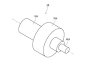
従来、電動機と減速機とを備え、電動機から得られる動力を減速させて出力する電動機付き減速機が知られている。図6は、従来の電動機付き減速機1Xの構造を、概念的に示した図である。図6の電動機付き減速機1Xは、電動機10Xと、減速機構70Xと、減速後の回転数で回転する出力部40Xと、を有する。電動機付き減速機1Xは、例えば、作業ロボットにおけるアームの関節部分に組み込まれる。そのため、電動機付き減速機1Xにおける、出力部に加わる外力を検出できる機構が求められる。
Conventionally, a speed reducer with an electric motor, which includes an electric motor and a speed reducer and reduces and outputs the power obtained from the electric motor, is known. FIG. 6 is a diagram conceptually showing the structure of the
電動機付き減速機の出力部に加わる外力を検出するために、例えば、電動機付き減速機にセンサを搭載することが、考えられる。センサを用いて電動機付き減速機にかかる負荷を検出する機構については、例えば、特開2008−068725号公報に記載されている。
特開2008−068725号公報には、電動モータによって減速機を介して回転する車輪のハブを支持する軸受の歪みを検出することにより、車輪と路面との接地点にかかる力を測定するセンサユニットの構造が示されている。しかしながら、当該センサユニットは、軸受の周方向の一部における歪みを検出する構造であるため、中心軸まわりのトルクを検出することが困難である。 Japanese Patent Application Laid-Open No. 2008-08725 describes a sensor unit that measures the force applied to the ground contact point between the wheel and the road surface by detecting the strain of the bearing supporting the hub of the wheel rotating via the speed reducer by the electric motor. The structure of is shown. However, since the sensor unit has a structure for detecting strain in a part of the bearing in the circumferential direction, it is difficult to detect torque around the central axis.
本発明の目的は、電動機付き減速機において、出力部に加わる中心軸まわりのトルクを含む負荷を検出できる構造を提供することである。 An object of the present invention is to provide a structure for detecting a load including torque around a central axis applied to an output unit in a speed reducer with an electric motor.
本願の例示的な第1発明は、第1中心軸の周りに軸方向に延びる中空の中空シャフトと、前記中空シャフトに直接または間接的に固定され、前記中空シャフトよりも径方向外側において軸方向に延びる筒状のケーシングと、前記中空シャフトの周りに広がり、前記ケーシングに対して相対的に静止する固定部と、前記中空シャフトの径方向外側において、前記第1中心軸と平行な第2中心軸に対して回転運動を発生させる電動機と、前記電動機から得られる回転運動を減速させながら伝達する減速機構と、前記固定部に第1軸受を介して回転可能に接続され、前記減速機構による減速後の回転数で第1中心軸に対して回転する出力部と、前記中空シャフトの周りに環状に広がり、前記ケーシングおよび前記固定部に接続されるトルクセンサと、を有し、前記トルクセンサは、環状の外輪および環状の内輪を有する弾性変形可能な起歪体と、複数の歪センサと、を有し、前記外輪は、前記トルクセンサの径方向外側の端部に位置し、前記ケーシングおよび前記固定部のいずれか一方に接続され、前記内輪は、前記トルクセンサの径方向内側の端部に位置し、前記ケーシングおよび前記固定部のいずれか他方に接続され、前記複数の歪センサはそれぞれ、少なくとも一部が前記外輪と前記内輪との径方向の間に位置する、電動機付き減速機である。 An exemplary first invention of the present application is a hollow hollow shaft extending axially around a first central axis and axially fixed to the hollow shaft and radially outside the hollow shaft. A tubular casing extending in, a fixing portion extending around the hollow shaft and stationary relative to the casing, and a second center parallel to the first central axis on the radial outer side of the hollow shaft. An electric motor that generates a rotary motion with respect to a shaft, a deceleration mechanism that transmits the rotary motion obtained from the electric motor while decelerating, and a deceleration mechanism that is rotatably connected to the fixed portion via a first bearing and decelerates by the deceleration mechanism. The torque sensor has an output unit that rotates with respect to the first central axis at a later rotation speed, and a torque sensor that expands in an annular shape around the hollow shaft and is connected to the casing and the fixed portion. The outer ring comprises an elastically deformable strain-generating body having an annular outer ring and an annular inner ring, and a plurality of strain sensors, the outer ring being located at the radial outer end of the torque sensor, the casing and the casing. Connected to one of the fixing portions, the inner ring is located at the radially inner end of the torque sensor and is connected to either the casing or the fixing portion, and the plurality of strain sensors are respectively. , At least a part of the speed reducer with an electric motor located between the outer ring and the inner ring in the radial direction.
本願の例示的な第1発明によれば、軸方向に延びる中空シャフトの周りに環状に広がるトルクセンサを有し、当該トルクセンサの外輪および内輪を、出力部に軸受を介して接続される固定部とケーシングとにそれぞれ接続することで、出力部に加わる中心軸まわりのトルクを含む負荷を検出することができる。 According to the first exemplary invention of the present application, the torque sensor has a torque sensor that extends in an annular shape around a hollow shaft extending in the axial direction, and the outer ring and the inner ring of the torque sensor are fixed to the output portion via bearings. By connecting the unit and the casing, respectively, it is possible to detect the load including the torque around the central axis applied to the output unit.
以下、本発明の例示的な実施形態について、図面を参照しながら説明する。なお、本願では、中空シャフトの中心軸(第1中心軸)と平行な方向を「軸方向」、中心軸(第1中心軸)に直交する方向を「径方向」、中心軸(第1中心軸)を中心とする円弧に沿う方向を「周方向」、とそれぞれ称する。ただし、上記の「平行な方向」は、略平行な方向も含む。また、上記の「直交する方向」は、略直交する方向も含む。また、以下では、説明の便宜上、図1中の電動機が配置される右側を「入力側」、図1中の出力部が配置される左側を「出力側」、とそれぞれ称する。ただし、この定義により、本発明に係る電動機付き減速機の使用時の向きを限定する意図はない。 Hereinafter, exemplary embodiments of the present invention will be described with reference to the drawings. In the present application, the direction parallel to the central axis (first central axis) of the hollow shaft is the "axial direction", the direction orthogonal to the central axis (first central axis) is the "diameter direction", and the central axis (first center). The directions along the arc centered on the axis) are referred to as "circumferential directions". However, the above-mentioned "parallel direction" also includes a substantially parallel direction. Further, the above-mentioned "orthogonal direction" includes a direction substantially orthogonal to each other. Further, in the following, for convenience of description, the right side where the electric motor is arranged in FIG. 1 is referred to as an “input side”, and the left side where the output unit in FIG. 1 is arranged is referred to as an “output side”. However, this definition does not intend to limit the orientation when the speed reducer with an electric motor according to the present invention is used.
<1.第1実施形態>
<1−1.電動機付き減速機の構成>
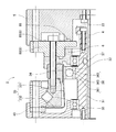
図1は、本発明の第1実施形態に係る電動機付き減速機1の縦断面図である。この電動機付き減速機1には、平歯車機構2と波動歯車機構3とから構成される減速機構7が用いられている。平歯車機構2は、第1歯車21と、当該第1歯車21の外歯よりも歯数の多い第2歯車22の外歯とを、互いに噛み合わせて連動回転させる機構である。波動歯車機構3は、剛性の内歯歯車34に弾性の可撓外歯歯車33を部分的に噛み合わせるとともに、弾性的な可撓性を利用することにより、その噛み合わせ位置を両歯車の歯数差によって周方向に移動させる機構である。詳細については後述する。
<1. First Embodiment>
<1-1. Configuration of reducer with electric motor>
FIG. 1 is a vertical cross-sectional view of the
この電動機付き減速機1は、電動機10における回転軸11の第1回転数の回転運動を、平歯車機構2により第1回転数よりも低い第2回転数の回転運動に変換して、さらに波動歯車機構3により第2回転数よりも低い第3回転数の回転運動に変換して、出力部40を回転させる機構である。電動機付き減速機1は、例えば、作業ロボットにおけるアームの関節部分に組み込まれて、アームの屈伸運動を実現させるために用いられる。ただし、本発明の電動機付き減速機は、アシストスーツ、ターンテーブル、工作機械の割出盤、車椅子、無人搬送車などの他の機器に組み込まれて、各種の回転運動を実現させるものであってもよい。
The speed reducer 1 with an electric motor converts the rotational movement of the first rotation number of the rotating
図1に示すように、本実施形態の電動機付き減速機1は、電動機10、中空シャフト4、ケーシング5、固定部6、減速機構7、出力部40、および後述するトルクセンサ8を有する。
As shown in FIG. 1, the speed reducer 1 with an electric motor of the present embodiment includes an
電動機10は、駆動電流に応じて回転運動を発生させる駆動源である。電動機10は、後述する中空シャフト4の径方向外側に配置される。また、電動機10は、ステータを有する静止部と、マグネットを有する回転部とを有する。静止部は、後述するケーシング5に、直接的にまたは間接的に固定され、相対的に静止している。また、回転部は、静止部に対して、第1中心軸9と平行な第2中心軸91を中心として回転可能に支持されている。
The
静止部に含まれるコイルに駆動電流を供給すると、コイルの磁芯である複数のティースに磁束が生じる。そして、ティースと、回転部に含まれるマグネットとの間の磁束の作用により、静止部と回転部との間に周方向のトルクが発生し、静止部に対して回転部が第2中心軸91を中心として回転する。これにより、中空シャフト4の径方向外側において、第2中心軸91に対する回転運動を発生させることができる。また、電動機10の回転部の一部であり、第2中心軸91に沿って延びる回転軸11が、第2中心軸91を中心として第1回転数で回転する。なお、電動機10を中空シャフト4の径方向外側に配置することで、電動機付き減速機1における第1中心軸9の周囲に中空構造を容易に設けることができる。これにより、電動機付き減速機1を構成する各部から引き出される配線を、中空構造の内部に纏めて設けることができる。
When a drive current is supplied to the coil included in the stationary portion, magnetic flux is generated in a plurality of teeth which are magnetic cores of the coil. Then, due to the action of the magnetic flux between the teeth and the magnet included in the rotating portion, torque in the circumferential direction is generated between the stationary portion and the rotating portion, and the rotating portion is the second
中空シャフト4は、電動機付き減速機1における入力側から出力側に延びる第1中心軸9の周りに軸方向に延びる中空(円筒状)の部材である。中空シャフト4および後述するケーシング5は、電動機付き減速機1が配置される筐体に対して、相対的に静止している。
The hollow shaft 4 is a hollow (cylindrical) member extending in the axial direction around the first central shaft 9 extending from the input side to the output side in the
ケーシング5は、中空シャフト4よりも径方向外側において軸方向に延びる筒状の部材である。本実施形態のケーシング5は、中空シャフト4にねじ止めによって直接的に固定される。ただし、ケーシング5は、別の部材を介して中空シャフト4に間接的に固定されてもよい。ケーシング5には、さらに電動機10の静止部が固定される。
The
固定部6は、中空シャフト4の周りに広がる部材である。固定部6は、ケーシング5よりも出力側に位置する。固定部6は、後述するトルクセンサ8を介してケーシング5に固定される。また、固定部6は、第1軸受35を介して後述する出力部40と回転可能に接続される。
The fixing
減速機構7は、電動機10から得られる回転運動を減速させながら出力部40へ伝達する機構である。減速機構7は、平歯車機構2と波動歯車機構3とを有する。
The
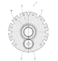
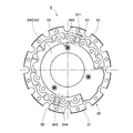
図2は、図1のA−A位置から見た電動機付き減速機1の横断面図である。図2では、平歯車機構2に含まれる各歯車21,22の外歯の図示が省略されている。図1および図2に示すように、平歯車機構2は、第1歯車21と第2歯車22とを有する。第1歯車21は、電動機10の回転軸11の外周面に固定される平歯車である。第1歯車21は、回転軸11とともに第2中心軸91を中心として第1回転数で回転する。第2歯車22は、中空シャフト4の径方向外側に環状に広がる平歯車である。第2歯車22は、第1歯車21と互いに噛み合い、第1中心軸9を中心として回転する。ただし、第2歯車22に設けられた外歯の数は、第1歯車21に設けられた外歯の数よりも多い。このため、第1歯車21が第2中心軸91を中心として第1回転数で回転するのに応じて、第2歯車22が、後述する筒状部31とともに、中空シャフト4の周りに、第1回転数よりも低い減速後の第2回転数で、第1中心軸9を中心として回転する。
FIG. 2 is a cross-sectional view of the
なお、第1歯車21と第2歯車22との接触箇所において、グリース等の潤滑オイル(図示省略)が保持される。これにより、第1歯車21と第2歯車22とが噛み合うことによる摩擦および摩耗が抑制される。
Lubricating oil (not shown) such as grease is held at the contact points between the
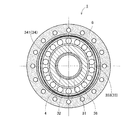
図3は、図1のB−B位置から見た電動機付き減速機1の横断面図である。図4は、第1実施形態に係る電動機付き減速機1の部分縦断面図である。図1、図3、および図4に示すように、電動機付き減速機1の波動歯車機構3は、可撓歯車を利用した歯車機構である。波動歯車機構3は、筒状部31、非真円カム32、可撓外歯歯車33、および第2軸受36を有する。また、本実施形態では、波動歯車機構3は、内歯歯車34をさらに有する。
FIG. 3 is a cross-sectional view of the
筒状部31は、中空シャフト4の周りに軸方向に延びる筒状の部材である。また、筒状部31の内周面は、第3軸受37を介して中空シャフト4に回転可能に支持されている。さらに、筒状部31は、第2歯車22と軸方向に隣接し、ねじ止めにより固定され、第2歯車22とともに、第1中心軸9を中心として第2回転数で回転する。
The
非真円カム32は、筒状部31の外周面に設けられた非真円の環状の部位である。本実施形態では、非真円カム32は筒状部31と一体になっている。図3に示すように、非真円カム32は、軸方向に見て楕円形で、第1中心軸9からの距離が一定でない外周面を有する。非真円カム32は、筒状部31とともに第1中心軸9を中心として第2回転数で回転する。
The
可撓外歯歯車33は、可撓筒部331とフランジ部332とを有する。可撓筒部331は、後述する内歯歯車34の径方向内側に配置される筒状の部位である。後述のとおり、可撓筒部331は、非真円カム32の回転に応じて変形する。可撓筒部331の外周面には、複数の外歯333が一定のピッチで設けられる。フランジ部332は、可撓筒部331の軸方向の端部から径方向外側に延びる。フランジ部332は、出力部40に、例えば、ねじ止めによって固定される。このように、可撓外歯歯車33は所謂オープン型の構造を有しており、電動機付き減速機1において中空構造が容易に形成される。
The flexible
第2軸受36は、非真円カム32と可撓外歯歯車33との径方向の間に介在する可撓性の軸受である。第2軸受36は、第2内輪361と、第2外輪362と、第2内輪361と第2外輪362との間に介在する複数の球体363と、を有する。第2内輪361と非真円カム32の楕円状の外周面とは、互いに固定される。また、第2外輪362と、可撓外歯歯車33の内周面とは、互いに固定される。なお、第2内輪361と非真円カム32とは、単一の部材で構成されていてもよい。また、第2外輪362と可撓外歯歯車33とは、単一の部材で構成されていてもよい。
The
内歯歯車34は、少なくとも一部が可撓外歯歯車33の径方向外側に位置する円環状の部材である。内歯歯車34は、固定部6にねじ止めによって固定される。なお、内歯歯車34は、固定部6と別に設けられるのではなく、固定部6の内周面に形成されてもよい。内歯歯車34の内周面には、複数の内歯341が、周方向に一定のピッチで設けられる。
The
出力部40は、中空シャフト4の径方向外側における、ケーシング5の出力側に配置される円環状の部材である。出力部40は、可撓外歯歯車33のフランジ部332と、ねじ止めによって固定される。また、出力部40と固定部6との間には、第1軸受35が介在する。これにより、出力部40は、第1軸受35を介して、固定部6に回転可能に接続される。
The
なお、本実施形態では、第1軸受35に、クロスローラベアリングが用いられる。第1軸受35は、出力部40の内周面と固定部6の外周面との間に、複数の円筒ころ(図示省略)を有する。複数の円筒ころは、出力部40の内周面に設けられた環状のV溝(図示省略)と、固定部6の外周面に設けられた環状のV溝(図示省略)との間に、向きを交互に変えながら配置される。これにより、固定部6に対する出力部40の回転を許容しながら、高剛性に接続される。
In this embodiment, a cross roller bearing is used for the
このようなクロスローラベアリングは、ボールベアリングのように一対で用いずとも、軸方向および径方向に、必要な剛性を得ることができる。すなわち、クロスローラベアリングを用いることで、固定部6と出力部40との間に介在するベアリングの数を減らすことができる。これにより、第1軸受35の重量を低減できるとともに、第1軸受35の軸方向の寸法を抑えることができる。
Such cross-roller bearings can obtain the required rigidity in the axial direction and the radial direction without using them in pairs like ball bearings. That is, by using the cross roller bearing, the number of bearings interposed between the fixed
なお、本実施形態では、出力部40の内周面を含む一部分が、第1軸受35の外輪として機能する。ただし、第1軸受35は、出力部40とは別に外輪を有していてもよい。また、本実施形態では、固定部6の外周面を含む一部分が、第1軸受35の内輪として機能する。ただし、第1軸受35は、固定部6とは別に内輪を有していてもよい。
In this embodiment, a part including the inner peripheral surface of the
筒状部31とともに非真円カム32が第2回転数で回転すると、非真円カム32の回転に応じて、可撓外歯歯車33の可撓筒部331の形状が変化する。すなわち、軸方向に見たときに、可撓筒部331は、第2軸受36を介して、非真円カム32の外周面の形状に沿った楕円形状となる。その楕円の長軸は、非真円カム32の回転に追従して周方向に移動する。可撓外歯歯車33は、外周面に設けられた複数の外歯333のうち、長軸の両端に位置する外歯333のみが、内歯歯車34の内歯341と噛み合う。
When the
このように、可撓外歯歯車33の複数の外歯333は、内歯歯車34の複数の内歯341と、周方向の一部分のみにおいて噛み合う。そして、その噛み合う位置が、非真円カム32の回転に応じて周方向に移動する。ただし、可撓外歯歯車33に設けられた外歯333の数と、内歯歯車34に設けられた内歯341の数とは、互いに異なる。このため、非真円カム32の1回転ごとに、可撓外歯歯車33の同じ位置の外歯333に噛み合う内歯歯車34の内歯341の位置がずれる。これにより、可撓外歯歯車33が、第1中心軸9を中心として、ゆっくりと回転する。つまり、可撓外歯歯車33は、内歯歯車34と、互いに噛み合うとともに、歯数の違いによって相対回転する。このときの可撓外歯歯車33の回転数は、非真円カム32の回転数よりも小さい、第3回転数となる。出力部40は、可撓外歯歯車33とともに、第3回転数で、第1中心軸9に対して回転する。このように、電動機10による第2中心軸91を中心とした第1回転数の回転を、平歯車機構2および波動歯車機構3を用いて減速し、減速後の第3回転数で、出力部40を、第1中心軸9を中心として回転させることができる。
In this way, the plurality of
<1−2.トルクセンサの構成>
続いて、トルクセンサ8の構成について説明する。図5は、軸方向に見たトルクセンサの平面図である。以下では、図5とともに、図1〜図4も適宜に参照する。
<1-2. Torque sensor configuration>
Subsequently, the configuration of the
トルクセンサ8は、中空シャフト4の周りに環状に広がる。また、トルクセンサ8は、入力側において、ケーシング5にねじ止めによって接続され、出力側において、固定部6にねじ止めによって接続される。図4および図5に示すように、トルクセンサ8は、起歪体80、センサ支持部84、および複数の歪センサ85を有する。
The
起歪体80は、環状の外輪81、環状の内輪82、および複数のリブ83を有する弾性変形可能な部材である。外輪81は、トルクセンサ8の径方向外側の端部に位置し、ケーシング5に接続される。また、内輪82は、トルクセンサ8の径方向内側の端部に位置し、固定部6に接続される。複数のリブ83は、互いに周方向に間隔を空けて配置される。複数のリブ83は、それぞれ外輪81と内輪82とを繋ぐ。なお、外輪81は固定部6に接続され、内輪82はケーシング5に接続されてもよい。つまり、外輪81は、ケーシング5および固定部6のいずれか一方に接続され、内輪82は、ケーシング5および固定部6のいずれか他方に接続されるものであればよい。
The strain-causing
センサ支持部84は、複数のリブ83と軸方向に近接しつつ、中空シャフト4の周りに円環状または円弧状に広がる部材である。また、センサ支持部84は、外輪81における第1位置841と、第1位置841と周方向に位置が異なる第2位置842と、において、それぞれ外輪81に接続される。また、センサ支持部84は、内輪82における、第1位置841の径方向内側に位置する第3位置843と、第2位置842の径方向内側に位置する第4位置844と、において、それぞれ内輪82に接続される。これにより、センサ支持部84は、外輪81と内輪82とを繋ぐ。なお、センサ支持部84と各リブ83は、周方向の位置が互いに異なってもよく、周方向の位置が互いに重なってもよい。なお、センサ支持部84の表面840は、第1中心軸9に直交する平面である。上述のとおり、センサ支持部84を設けることにより、起歪体80に後述の歪センサ85を容易に装着することができる。
The
電動機付き減速機1において、例えば、出力部40に第1中心軸9まわりのトルクを含む外力が加わる場合、当該外力は、第1軸受35および固定部6を介して、トルクセンサ8に伝達される。具体的には、当該外力が、起歪体80の内輪82に伝達される。これにより、トルクセンサ8の起歪体80、センサ支持部84、および後述する歪センサ85が変位する。
In the
なお、トルクセンサ8のうち、少なくともセンサ支持部84はステンレス製である。これにより、上述の外力によるセンサ支持部84の変位量をより大きくすることができる。さらに、トルクセンサ8のうち、センサ支持部84をステンレス製とし、外輪81、内輪82、および複数のリブ83を有する起歪体80をステンレスよりも剛性の高い金属製とすることで、センサ支持部84に変位を集中させることができる。これにより、センサ支持部84における、特に外輪81と内輪82との径方向の間の変位量をさらに大きくすることができる。また、トルクセンサ8の全体の剛性が維持されるため、電動機付き減速機1の回転への影響が抑制される。
Of the
複数の歪センサ85は、それぞれセンサ支持部84の表面840に接着により固定される。また、複数の歪センサ85は、それぞれ少なくとも一部が外輪81と内輪82との径方向の間に位置する。これにより、出力部40に加わる外力を、センサ支持部84の変位により生じる各歪センサ85の出力の変化から検出することができる。
Each of the plurality of
なお、トルクセンサ8には、さらに基板(図示省略)が搭載される。基板は、複数の歪センサ85とそれぞれ電気的に接続される。また、基板と接続された配線(図示省略)が、トルクセンサ8の外側に引き出される。これにより、各歪センサ85からの出力信号を、外部の検出装置(図示省略)に伝達することができる。
A substrate (not shown) is further mounted on the
なお、本実施形態では、2つの歪センサ85が固定されている。図5に示すとおり、2つの歪センサ85は、それぞれ第1位置841と第3位置843との径方向の間、および第2位置842と第4位置844との径方向の間に位置する。すなわち、2つの歪センサ85は、センサ支持部84の周方向において互いに第1中心軸9を介して対向する。これにより、2つの歪センサ85の出力の変化を比較し、さらに分析することで、出力部40に加わる外力を、第1中心軸9方向の力と、第1中心軸9を中心としたトルクとに区別して、検出することができる。
In this embodiment, the two
なお、センサ支持部84に固定される歪センサ85の数は、3つ以上であってもよい。3つ以上の場合、例えば、複数の歪センサ85のうち少なくとも2つが互いに第1中心軸9を介して対向するように配置してもよい。また、3つ以上の歪センサ85を、互いに周方向に等間隔に配置してもよい。より多くの歪センサ85を用いることで、出力部40に加わる外力を、軸方向の力と、径方向の力と、第1中心軸9を中心としたトルクとに細かく区別して、検出することができる。
The number of
なお、トルクセンサ8の起歪体80における、第1歯車21と軸方向に対向する面の少なくとも一部が、板状部材86によって塞がれる。これにより、第1歯車21と第2歯車22との接触箇所において保持されるグリース等の潤滑オイル(図示省略)が、トルクセンサ8の内部に到達することを抑制できる。この結果、トルクセンサ8の空洞を介して潤滑オイルが電動機付き減速機1の外部へ漏れることを抑制できる。
At least a part of the surface of the
なお、電動機付き減速機1は、さらに中空シャフト4の周囲に環状のオイルシール87を有する。また、ケーシング5の少なくとも一部とトルクセンサ8の少なくとも一部とが、軸方向においてオイルシール87を介して接合される。これにより、第1歯車21と第2歯車22との接触箇所において保持されるグリース等の潤滑オイル(図示省略)が、トルクセンサ8の内部に到達することを抑制できる。この結果、トルクセンサ8の空洞を介して潤滑オイルが電動機付き減速機1の外部へ漏れることを抑制できる。なお、オイルシール87は、一部が板状部材86から連続して配置されてもよく、板状部材86と一体であってもよい。さらに、オイルシール87は、ケーシング5と板状部材86との両方に跨って配置されてもよい。
The
<2.変形例>
以上、本発明の例示的な実施形態について説明したが、本発明は上記の実施形態には限定されない。
<2. Modification example>
Although the exemplary embodiments of the present invention have been described above, the present invention is not limited to the above embodiments.
第1実施形態の可撓外歯歯車33は、非真円カム32の回転に応じて変形する筒状の可撓筒部331、およびフランジ部332から形成される、所謂オープン型の構造を有する。しかし、可撓外歯歯車33は、非真円カム32の回転に応じて変形する可撓筒部331、および可撓筒部の端部から径方向内側に延びる円板部(図示省略)から形成される、所謂クローズ型の構造を有してもよい。さらに、可撓外歯歯車33は、非真円カムの回転に応じて変形する可撓筒部331のみから形成されてもよい。
The flexible
また、第1実施形態では、可撓外歯歯車33は出力部40に固定され、内歯歯車34は固定部6に固定される。しかし、可撓外歯歯車33は固定部6に固定され、内歯歯車34は出力部40に固定されてもよい。この場合、内歯歯車34は、可撓外歯歯車33と互いに噛み合うとともに、歯数の違いによって相対回転する。
Further, in the first embodiment, the flexible
第1実施形態のトルクセンサ8は、出力部40に加わり、第1軸受35および固定部6を介して、トルクセンサ8に伝達される外力を、複数の歪センサ85を用いて検出する。しかし、複数の歪センサ85を用いる代わりに、または複数の歪センサ85を用いるのに加えて、例えば、静電容量型センサ等の他の構造を有するセンサを用いてもよい。
The
上記の電動機付き減速機を構成する各部材の材料には、例えば、高強度の金属が用いられる。しかし、各部材の材料は、使用時の負荷に耐え得るものであればよく、必ずしも金属には限定されない。 For example, a high-strength metal is used as the material of each member constituting the above-mentioned speed reducer with an electric motor. However, the material of each member may be any material that can withstand the load during use, and is not necessarily limited to metal.
また、電動機付き減速機の細部の形状については、本願の各図に示された形状と、相違していてもよい。また、上記の実施形態や変形例に登場した各要素を、矛盾が生じない範囲で、適宜に組み合わせてもよい。 Further, the detailed shape of the speed reducer with an electric motor may be different from the shape shown in each figure of the present application. Further, the elements appearing in the above-described embodiments and modifications may be appropriately combined as long as there is no contradiction.
本発明は、電動機付き減速機に利用できる。 The present invention can be used for a speed reducer with an electric motor.
1,1X 電動機付き減速機
2 平歯車機構
3 波動歯車機構
4 中空シャフト
5 ケーシング
6 固定部
7 減速機構
8 トルクセンサ
9 第1中心軸
10,10X 電動機
11 電動機の回転軸
21 第1歯車
22 第2歯車
31 筒状部
32 非真円カム
33 可撓外歯歯車
34 内歯歯車
35 第1軸受
36 第2軸受
37 第3軸受
40,40X 出力部
70X 減速機構
80 起歪体
81 外輪
82 内輪
83 リブ
84 センサ支持部
85 歪センサ
86 板状部材
87 オイルシール
91 第2中心軸
331 可撓筒部
332 フランジ部
333 外歯
341 内歯
361 第2内輪
362 第2外輪
363 球体
840 表面
841 第1位置
842 第2位置
843 第3位置
844 第4位置
1,1X Reducer with
Claims (11)
前記中空シャフトに直接または間接的に固定され、前記中空シャフトよりも径方向外側において軸方向に延びる筒状のケーシングと、
前記中空シャフトの周りに広がり、前記ケーシングに対して相対的に静止する固定部と、
前記中空シャフトの径方向外側において、前記第1中心軸と平行な第2中心軸に対して回転運動を発生させる電動機と、
前記電動機から得られる回転運動を減速させながら伝達する減速機構と、
前記固定部に第1軸受を介して回転可能に接続され、前記減速機構による減速後の回転数で第1中心軸に対して回転する出力部と、
前記中空シャフトの周りに環状に広がり、前記ケーシングおよび前記固定部に接続されるトルクセンサと、
を有し、
前記トルクセンサは、
環状の外輪および環状の内輪を有する弾性変形可能な起歪体と、
複数の歪センサと、
を有し、
前記外輪は、前記トルクセンサの径方向外側の端部に位置し、前記ケーシングおよび前記固定部のいずれか一方に接続され、
前記内輪は、前記トルクセンサの径方向内側の端部に位置し、前記ケーシングおよび前記固定部のいずれか他方に接続され、
前記複数の歪センサはそれぞれ、少なくとも一部が前記外輪と前記内輪との径方向の間に位置し、
前記トルクセンサは、さらに
前記外輪と前記内輪とを繋ぐセンサ支持部
を有し、
前記センサ支持部は、前記外輪における第1位置と前記第1位置と周方向に位置が異なる第2位置とにおいてそれぞれ前記外輪に接続され、さらに
前記センサ支持部は、前記内輪における、前記第1位置の径方向内側に位置する第3位置、および前記第2位置の径方向内側に位置する第4位置において、それぞれ前記内輪に接続され、
前記複数の歪センサはそれぞれ前記センサ支持部に固定される、電動機付き減速機。 A hollow hollow shaft extending axially around the first central axis,
A tubular casing that is directly or indirectly fixed to the hollow shaft and extends axially outward of the hollow shaft.
A fixed portion that extends around the hollow shaft and rests relative to the casing.
An electric motor that generates a rotational motion with respect to a second central axis parallel to the first central axis on the radial outer side of the hollow shaft.
A deceleration mechanism that transmits the rotational motion obtained from the electric motor while decelerating it,
An output unit that is rotatably connected to the fixed portion via a first bearing and rotates with respect to the first central axis at the rotation speed after deceleration by the deceleration mechanism.
A torque sensor that circulates around the hollow shaft and is connected to the casing and the fixing portion.
Have,
The torque sensor is
An elastically deformable strain-generating body having an annular outer ring and an annular inner ring,
With multiple strain sensors
Have,
The outer ring is located at the radial outer end of the torque sensor and is connected to either the casing or the fixing portion.
The inner ring is located at the radial inner end of the torque sensor and is connected to either the casing or the fixing portion.
Each of the plurality of strain sensors is located at least in part in the radial direction between the outer ring and the inner ring .
The torque sensor further
Sensor support portion that connects the outer ring and the inner ring
Have,
The sensor support portion is connected to the outer ring at a first position on the outer ring and a second position different from the first position in the circumferential direction, and further.
The sensor support portion is connected to the inner ring at a third position located radially inside the first position and a fourth position located radially inside the second position of the inner ring, respectively.
Each of the plurality of strain sensors is fixed to the sensor support portion, and is a speed reducer with an electric motor.
前記中空シャフトに直接または間接的に固定され、前記中空シャフトよりも径方向外側において軸方向に延びる筒状のケーシングと、
前記中空シャフトの周りに広がり、前記ケーシングに対して相対的に静止する固定部と、
前記中空シャフトの径方向外側において、前記第1中心軸と平行な第2中心軸に対して回転運動を発生させる電動機と、
前記電動機から得られる回転運動を減速させながら伝達する減速機構と、
前記固定部に第1軸受を介して回転可能に接続され、前記減速機構による減速後の回転数で第1中心軸に対して回転する出力部と、
前記中空シャフトの周りに環状に広がり、前記ケーシングおよび前記固定部に接続されるトルクセンサと、
を有し、
前記トルクセンサは、
環状の外輪および環状の内輪を有する弾性変形可能な起歪体と、
複数の歪センサと、
を有し、
前記外輪は、前記トルクセンサの径方向外側の端部に位置し、前記ケーシングおよび前記固定部のいずれか一方に接続され、
前記内輪は、前記トルクセンサの径方向内側の端部に位置し、前記ケーシングおよび前記固定部のいずれか他方に接続され、
前記複数の歪センサはそれぞれ、少なくとも一部が前記外輪と前記内輪との径方向の間に位置し、
前記ケーシングの少なくとも一部と前記トルクセンサの少なくとも一部とが軸方向において環状のオイルシールを介して接合される、電動機付き減速機。 A hollow hollow shaft extending axially around the first central axis,
A tubular casing that is directly or indirectly fixed to the hollow shaft and extends axially outward of the hollow shaft.
A fixed portion that extends around the hollow shaft and rests relative to the casing.
An electric motor that generates a rotational motion with respect to a second central axis parallel to the first central axis on the radial outer side of the hollow shaft.
A deceleration mechanism that transmits the rotational motion obtained from the electric motor while decelerating it,
An output unit that is rotatably connected to the fixed portion via a first bearing and rotates with respect to the first central axis at the rotation speed after deceleration by the deceleration mechanism.
A torque sensor that circulates around the hollow shaft and is connected to the casing and the fixing portion.
Have,
The torque sensor is
An elastically deformable strain-generating body having an annular outer ring and an annular inner ring,
With multiple strain sensors
Have,
The outer ring is located at the radial outer end of the torque sensor and is connected to either the casing or the fixing portion.
The inner ring is located at the radial inner end of the torque sensor and is connected to either the casing or the fixing portion.
Each of the plurality of strain sensors is located at least in part in the radial direction between the outer ring and the inner ring .
A speed reducer with an electric motor in which at least a part of the casing and at least a part of the torque sensor are joined via an annular oil seal in the axial direction .
前記中空シャフトに直接または間接的に固定され、前記中空シャフトよりも径方向外側において軸方向に延びる筒状のケーシングと、
前記中空シャフトの周りに広がり、前記ケーシングに対して相対的に静止する固定部と、
前記中空シャフトの径方向外側において、前記第1中心軸と平行な第2中心軸に対して回転運動を発生させる電動機と、
前記電動機から得られる回転運動を減速させながら伝達する減速機構と、
前記固定部に第1軸受を介して回転可能に接続され、前記減速機構による減速後の回転数で第1中心軸に対して回転する出力部と、
前記中空シャフトの周りに環状に広がり、前記ケーシングおよび前記固定部に接続されるトルクセンサと、
を有し、
前記トルクセンサは、
環状の外輪および環状の内輪を有する弾性変形可能な起歪体と、
複数の歪センサと、
を有し、
前記外輪は、前記トルクセンサの径方向外側の端部に位置し、前記ケーシングおよび前記固定部のいずれか一方に接続され、
前記内輪は、前記トルクセンサの径方向内側の端部に位置し、前記ケーシングおよび前記固定部のいずれか他方に接続され、
前記複数の歪センサはそれぞれ、少なくとも一部が前記外輪と前記内輪との径方向の間に位置し、
前記減速機構は、
前記電動機の回転軸に固定され、前記回転軸とともに前記第2中心軸を中心として回転する第1歯車と、
前記第1歯車と互いに噛み合い、前記第1中心軸を中心として回転する第2歯車と、
前記中空シャフトの周りに軸方向に延び、前記第2歯車が固定され、前記第1中心軸を中心として回転する筒状部と、
前記第1中心軸からの距離が一定でない外周面をもち、前記筒状部とともに前記第1中心軸を中心として回転する非真円カムと、
前記非真円カムの回転に応じて変形する可撓外歯歯車と、
少なくとも一部が前記可撓外歯歯車の径方向外側に位置する内歯歯車と、
を有し、
前記可撓外歯歯車と前記内歯歯車とが、互いに噛み合うとともに、歯数の違いによって相対回転し、
前記起歪体における前記第1歯車と軸方向に対向する面の少なくとも一部が、板状部材によって塞がれる、電動機付き減速機。 A hollow hollow shaft extending axially around the first central axis,
A tubular casing that is directly or indirectly fixed to the hollow shaft and extends axially outward of the hollow shaft.
A fixed portion that extends around the hollow shaft and rests relative to the casing.
An electric motor that generates a rotational motion with respect to a second central axis parallel to the first central axis on the radial outer side of the hollow shaft.
A deceleration mechanism that transmits the rotational motion obtained from the electric motor while decelerating it,
An output unit that is rotatably connected to the fixed portion via a first bearing and rotates with respect to the first central axis at the rotation speed after deceleration by the deceleration mechanism.
A torque sensor that circulates around the hollow shaft and is connected to the casing and the fixing portion.
Have,
The torque sensor is
An elastically deformable strain-generating body having an annular outer ring and an annular inner ring,
With multiple strain sensors
Have,
The outer ring is located at the radial outer end of the torque sensor and is connected to either the casing or the fixing portion.
The inner ring is located at the radial inner end of the torque sensor and is connected to either the casing or the fixing portion.
Each of the plurality of strain sensors is located at least in part in the radial direction between the outer ring and the inner ring.
The deceleration mechanism
A first gear that is fixed to the rotating shaft of the electric motor and rotates around the second central shaft together with the rotating shaft.
A second gear that meshes with the first gear and rotates about the first central axis.
A tubular portion that extends axially around the hollow shaft, has the second gear fixed, and rotates about the first central axis.
A non-perfect circular cam having an outer peripheral surface whose distance from the first central axis is not constant and rotating around the first central axis together with the tubular portion.
A flexible external gear that deforms according to the rotation of the non-round cam,
At least a part of the internal gear located on the radial outer side of the flexible external gear,
Have,
The flexible external gear and the internal gear mesh with each other and rotate relative to each other due to the difference in the number of teeth.
A speed reducer with an electric motor in which at least a part of a surface of the strain generating body that faces the first gear in the axial direction is closed by a plate-shaped member .
前記複数の歪センサのうち少なくとも2つは、互いに前記第1中心軸を介して対向する、電動機付き減速機。 The speed reducer with an electric motor according to any one of claims 1 to 3 .
At least two of the plurality of strain sensors are electric speed reducers facing each other via the first central axis.
前記トルクセンサのうち、少なくとも前記センサ支持部はステンレス製である、電動機付き減速機。 The speed reducer with an electric motor according to claim 1 .
A speed reducer with an electric motor in which at least the sensor support portion of the torque sensor is made of stainless steel.
前記歪センサは前記センサ支持部に接着により固定される、電動機付き減速機。 The speed reducer with an electric motor according to claim 1 or 5 .
The strain sensor is a speed reducer with an electric motor, which is fixed to the sensor support portion by adhesion.
前記減速機構は、さらに、
前記非真円カムと前記可撓外歯歯車との間に介在する可撓性の第2軸受
を有し、
前記第2軸受は、第2内輪、第2外輪、および前記第2内輪と前記第2外輪との間に介在する複数の球体を有し、
前記第2内輪と前記非真円カムとが、互いに固定されるか、または単一の部材である電動機付き減速機。 The speed reducer with an electric motor according to claim 3 .
The deceleration mechanism further
It has a flexible second bearing interposed between the non-round cam and the flexible external gear.
The second bearing has a second inner ring, a second outer ring, and a plurality of spheres interposed between the second inner ring and the second outer ring.
A speed reducer with an electric motor in which the second inner ring and the non-round cam are fixed to each other or are a single member.
前記第1軸受は、クロスローラベアリングである、電動機付き減速機。 The speed reducer with an electric motor according to any one of claims 1 to 7.
The first bearing is a speed reducer with an electric motor, which is a cross roller bearing.
前記可撓外歯歯車は、複数の外歯をもつ筒状の可撓筒部および前記可撓筒部の端部から径方向外側に延びるフランジ部を有する電動機付き減速機。 The speed reducer with an electric motor according to any one of claims 3, 7, and 8 .
The flexible external tooth gear is a speed reducer with an electric motor having a tubular flexible tubular portion having a plurality of external teeth and a flange portion extending radially outward from the end of the flexible tubular portion.
前記可撓外歯歯車は、複数の外歯をもつ筒状の可撓筒部および前記可撓筒部の端部から径方向内側に延びる円板部からなる電動機付き減速機。 The speed reducer with an electric motor according to any one of claims 3, 7, and 8 .
The flexible external tooth gear is a speed reducer with an electric motor including a tubular flexible tubular portion having a plurality of external teeth and a disk portion extending radially inward from the end of the flexible tubular portion.
前記減速機構における、前記第1歯車と前記第2歯車との接触箇所において、潤滑オイルが保持される、電動機付き減速機。 The speed reducer with an electric motor according to any one of claims 3, 7, 8, 8, 9, and 10 .
A speed reducer with an electric motor in which lubricating oil is held at a contact point between the first gear and the second gear in the speed reduction mechanism.
Priority Applications (6)
| Application Number | Priority Date | Filing Date | Title |
|---|---|---|---|
| JP2017027438A JP6817841B2 (en) | 2017-02-17 | 2017-02-17 | Reducer with electric motor |
| TW107105228A TWI655833B (en) | 2017-02-17 | 2018-02-13 | Reducer with motor |
| US16/485,446 US11041557B2 (en) | 2017-02-17 | 2018-02-15 | Speed reducer with electric motor |
| PCT/JP2018/005248 WO2018151210A1 (en) | 2017-02-17 | 2018-02-15 | Speed reducer with electric motor |
| CN201880012246.7A CN110300863A (en) | 2017-02-17 | 2018-02-15 | Has the speed reducer of motor |
| EP18754817.7A EP3584466A4 (en) | 2017-02-17 | 2018-02-15 | Speed reducer with electric motor |
Applications Claiming Priority (1)
| Application Number | Priority Date | Filing Date | Title |
|---|---|---|---|
| JP2017027438A JP6817841B2 (en) | 2017-02-17 | 2017-02-17 | Reducer with electric motor |
Publications (2)
| Publication Number | Publication Date |
|---|---|
| JP2018132154A JP2018132154A (en) | 2018-08-23 |
| JP6817841B2 true JP6817841B2 (en) | 2021-01-20 |
Family
ID=63170324
Family Applications (1)
| Application Number | Title | Priority Date | Filing Date |
|---|---|---|---|
| JP2017027438A Active JP6817841B2 (en) | 2017-02-17 | 2017-02-17 | Reducer with electric motor |
Country Status (6)
| Country | Link |
|---|---|
| US (1) | US11041557B2 (en) |
| EP (1) | EP3584466A4 (en) |
| JP (1) | JP6817841B2 (en) |
| CN (1) | CN110300863A (en) |
| TW (1) | TWI655833B (en) |
| WO (1) | WO2018151210A1 (en) |
Families Citing this family (11)
| Publication number | Priority date | Publication date | Assignee | Title |
|---|---|---|---|---|
| JP2017227315A (en) * | 2016-06-24 | 2017-12-28 | 日本電産シンポ株式会社 | Wave gear speed reducer unit |
| JP6695649B2 (en) * | 2017-10-19 | 2020-05-20 | 株式会社ハーモニック・ドライブ・システムズ | Wave gearing having three-dimensional meshing tooth profile |
| JP7085822B2 (en) * | 2017-11-28 | 2022-06-17 | 住友重機械工業株式会社 | Gear motor and its assembly method |
| TWI662204B (en) * | 2018-09-21 | 2019-06-11 | 上銀科技股份有限公司 | Harmonic reducer with an oil guiding ring |
| JP2020116693A (en) * | 2019-01-24 | 2020-08-06 | キヤノン株式会社 | Joint device, robot arm, torque and rotation angle detection device, and article manufacturing method |
| DE102019119658A1 (en) * | 2019-07-19 | 2021-01-21 | Pilz Gmbh & Co. Kg | Cycloid gear with torque detection device |
| JP7427933B2 (en) * | 2019-11-28 | 2024-02-06 | セイコーエプソン株式会社 | drive device |
| DE102020107674B3 (en) * | 2020-03-19 | 2021-08-05 | Harmonic Drive Se | Tension wave gear unit with integrated sensor |
| WO2021193244A1 (en) * | 2020-03-24 | 2021-09-30 | 住友重機械工業株式会社 | Flexible meshing type gear device |
| US11788581B2 (en) | 2020-04-27 | 2023-10-17 | Harmonic Drive Systems Inc. | Bearing unit and strain wave gearing |
| EP4170199A4 (en) | 2021-08-27 | 2024-03-06 | Harmonic Drive Systems | Strain wave gear device and actuator |
Family Cites Families (21)
| Publication number | Priority date | Publication date | Assignee | Title |
|---|---|---|---|---|
| JPS5947494B2 (en) | 1977-01-28 | 1984-11-19 | 株式会社日立製作所 | surface acoustic wave filter |
| JP2006200984A (en) * | 2005-01-19 | 2006-08-03 | Toyota Motor Corp | Dynamic characteristic measuring device and method for planetary gear mechanism |
| JP4605560B2 (en) * | 2005-12-05 | 2011-01-05 | 日本電産サンキョー株式会社 | Industrial robot |
| WO2007082594A2 (en) | 2006-01-20 | 2007-07-26 | Abb Ab | Drive unit comprising an electric rotating actuator and a wave gear speed reducer |
| JP4931525B2 (en) | 2006-09-14 | 2012-05-16 | Ntn株式会社 | Wheel bearing device with in-wheel motor built-in sensor |
| TWI367840B (en) * | 2009-04-03 | 2012-07-11 | Ind Tech Res Inst | Electric power steering controller |
| JP5480562B2 (en) * | 2009-08-26 | 2014-04-23 | 日本電産サンキョー株式会社 | Industrial robot |
| JP5818346B2 (en) * | 2011-04-27 | 2015-11-18 | 日本電産サンキョー株式会社 | Rotating body rotation range regulating mechanism and industrial robot |
| JP5818345B2 (en) * | 2011-04-27 | 2015-11-18 | 日本電産サンキョー株式会社 | Rotation mechanism, industrial robot, and method of returning origin of rotating body |
| JP5947494B2 (en) * | 2011-06-30 | 2016-07-06 | トヨタ自動車株式会社 | Method for manufacturing torque measuring device |
| CN103206494B (en) * | 2012-01-11 | 2016-12-28 | 株式会社捷太格特 | Reducing gear and possess the motor torque transmission device of this reducing gear |
| US9293962B2 (en) * | 2012-03-30 | 2016-03-22 | Korea Institute Of Machinery & Materials | Hollow driving module |
| WO2015020089A1 (en) * | 2013-08-09 | 2015-02-12 | 日本電産サンキョー株式会社 | Horizontal multi-joint robot and production method for horizontal multi-joint robot |
| EP3120979A4 (en) * | 2014-03-14 | 2017-11-08 | Sony Corporation | Robot arm device, robot arm control method and program |
| CN204835815U (en) * | 2014-07-24 | 2015-12-02 | 日本电产新宝株式会社 | Speed reducer of electrified motivation |
| JP5822008B1 (en) * | 2014-08-08 | 2015-11-24 | 日本精工株式会社 | Angle detection device, motor equipped with this angle detection device, torque sensor, electric power steering device, and automobile |
| US9988072B2 (en) * | 2015-05-29 | 2018-06-05 | Jtekt Corporation | Steering apparatus |
| PL3325225T3 (en) * | 2015-07-21 | 2022-05-23 | Kassow Robots Aps | Joint assembly |
| JP6535533B2 (en) | 2015-07-24 | 2019-06-26 | トヨタホーム株式会社 | Design support apparatus and design support program |
| TW201723448A (en) * | 2015-12-23 | 2017-07-01 | Prodrives & Motions Co Ltd | Axial rotation torque sensor allows one end of the elastic piece to sensitively produce bending and deformation under state of force received |
| TWM533743U (en) * | 2016-07-28 | 2016-12-11 | Chieh-Chi Chen | Torque sensor |
-
2017
- 2017-02-17 JP JP2017027438A patent/JP6817841B2/en active Active
-
2018
- 2018-02-13 TW TW107105228A patent/TWI655833B/en not_active IP Right Cessation
- 2018-02-15 EP EP18754817.7A patent/EP3584466A4/en not_active Withdrawn
- 2018-02-15 US US16/485,446 patent/US11041557B2/en active Active
- 2018-02-15 CN CN201880012246.7A patent/CN110300863A/en active Pending
- 2018-02-15 WO PCT/JP2018/005248 patent/WO2018151210A1/en unknown
Also Published As
| Publication number | Publication date |
|---|---|
| CN110300863A (en) | 2019-10-01 |
| EP3584466A1 (en) | 2019-12-25 |
| WO2018151210A1 (en) | 2018-08-23 |
| JP2018132154A (en) | 2018-08-23 |
| US20200003256A1 (en) | 2020-01-02 |
| TW201832450A (en) | 2018-09-01 |
| TWI655833B (en) | 2019-04-01 |
| EP3584466A4 (en) | 2020-10-21 |
| US11041557B2 (en) | 2021-06-22 |
Similar Documents
| Publication | Publication Date | Title |
|---|---|---|
| JP6817841B2 (en) | Reducer with electric motor | |
| JP6599220B2 (en) | Reducer with electric motor | |
| JP5285606B2 (en) | Reducer with motor and industrial machine | |
| JP6601836B2 (en) | Reducer with electric motor | |
| JP6699213B2 (en) | Reducer with electric motor | |
| JP6658877B2 (en) | Actuator | |
| KR20140044857A (en) | Internally-toothed gear unit with composite roller bearing, and wave gear device | |
| JP2011188542A (en) | Driving motor for electric vehicle | |
| JP6567204B2 (en) | Decelerator | |
| WO2017145836A1 (en) | Drive device | |
| JP6808474B2 (en) | Absolute encoder for motor with gear | |
| JP6590733B2 (en) | Reducer with electric motor | |
| JP2016084918A (en) | Traction power transmission device | |
| TWI551792B (en) | A reduction gear with a motor | |
| JP6237205B2 (en) | Planetary gear mechanism | |
| JP2015074036A (en) | Actuator, and robot joint structure provided with the same | |
| JP2010101447A (en) | Speed reducer with rotation detector | |
| JP2021042848A (en) | Wave gear device | |
| JP2022090472A (en) | Bearing device with rotation sensor | |
| JP4185746B2 (en) | Relative rotation state detection device | |
| TW202012811A (en) | Drive device | |
| JP6713363B2 (en) | transmission | |
| JP4707499B2 (en) | Rotation drive mechanism | |
| JP2022090471A (en) | Bearing device with rotation sensor | |
| JP2007178436A (en) | Relative rotational state detector |
Legal Events
| Date | Code | Title | Description |
|---|---|---|---|
| A625 | Written request for application examination (by other person) |
Free format text: JAPANESE INTERMEDIATE CODE: A625 Effective date: 20191220 |
|
| A131 | Notification of reasons for refusal |
Free format text: JAPANESE INTERMEDIATE CODE: A131 Effective date: 20200630 |
|
| A521 | Request for written amendment filed |
Free format text: JAPANESE INTERMEDIATE CODE: A523 Effective date: 20200831 |
|
| RD02 | Notification of acceptance of power of attorney |
Free format text: JAPANESE INTERMEDIATE CODE: A7422 Effective date: 20200831 |
|
| A521 | Request for written amendment filed |
Free format text: JAPANESE INTERMEDIATE CODE: A523 Effective date: 20201102 |
|
| TRDD | Decision of grant or rejection written | ||
| A01 | Written decision to grant a patent or to grant a registration (utility model) |
Free format text: JAPANESE INTERMEDIATE CODE: A01 Effective date: 20201124 |
|
| A61 | First payment of annual fees (during grant procedure) |
Free format text: JAPANESE INTERMEDIATE CODE: A61 Effective date: 20201225 |
|
| R150 | Certificate of patent or registration of utility model |
Ref document number: 6817841 Country of ref document: JP Free format text: JAPANESE INTERMEDIATE CODE: R150 |
|
| S111 | Request for change of ownership or part of ownership |
Free format text: JAPANESE INTERMEDIATE CODE: R313117 |
|
| S531 | Written request for registration of change of domicile |
Free format text: JAPANESE INTERMEDIATE CODE: R313531 |
|
| S533 | Written request for registration of change of name |
Free format text: JAPANESE INTERMEDIATE CODE: R313533 |
|
| R250 | Receipt of annual fees |
Free format text: JAPANESE INTERMEDIATE CODE: R250 |
|
| R371 | Transfer withdrawn |
Free format text: JAPANESE INTERMEDIATE CODE: R371 |
|
| R350 | Written notification of registration of transfer |
Free format text: JAPANESE INTERMEDIATE CODE: R350 |
|
| S111 | Request for change of ownership or part of ownership |
Free format text: JAPANESE INTERMEDIATE CODE: R313117 |
|
| R350 | Written notification of registration of transfer |
Free format text: JAPANESE INTERMEDIATE CODE: R350 |