JP6817780B2 - Distance measuring device and control method of range measuring device - Google Patents
Distance measuring device and control method of range measuring device Download PDFInfo
- Publication number
- JP6817780B2 JP6817780B2 JP2016206912A JP2016206912A JP6817780B2 JP 6817780 B2 JP6817780 B2 JP 6817780B2 JP 2016206912 A JP2016206912 A JP 2016206912A JP 2016206912 A JP2016206912 A JP 2016206912A JP 6817780 B2 JP6817780 B2 JP 6817780B2
- Authority
- JP
- Japan
- Prior art keywords
- data
- resolution
- degrees
- low
- unit
- Prior art date
- Legal status (The legal status is an assumption and is not a legal conclusion. Google has not performed a legal analysis and makes no representation as to the accuracy of the status listed.)
- Active
Links
Images


Classifications
-
- G—PHYSICS
- G01—MEASURING; TESTING
- G01S—RADIO DIRECTION-FINDING; RADIO NAVIGATION; DETERMINING DISTANCE OR VELOCITY BY USE OF RADIO WAVES; LOCATING OR PRESENCE-DETECTING BY USE OF THE REFLECTION OR RERADIATION OF RADIO WAVES; ANALOGOUS ARRANGEMENTS USING OTHER WAVES
- G01S17/00—Systems using the reflection or reradiation of electromagnetic waves other than radio waves, e.g. lidar systems
- G01S17/88—Lidar systems specially adapted for specific applications
- G01S17/89—Lidar systems specially adapted for specific applications for mapping or imaging
- G01S17/894—3D imaging with simultaneous measurement of time-of-flight at a 2D array of receiver pixels, e.g. time-of-flight cameras or flash lidar
-
- G—PHYSICS
- G01—MEASURING; TESTING
- G01S—RADIO DIRECTION-FINDING; RADIO NAVIGATION; DETERMINING DISTANCE OR VELOCITY BY USE OF RADIO WAVES; LOCATING OR PRESENCE-DETECTING BY USE OF THE REFLECTION OR RERADIATION OF RADIO WAVES; ANALOGOUS ARRANGEMENTS USING OTHER WAVES
- G01S17/00—Systems using the reflection or reradiation of electromagnetic waves other than radio waves, e.g. lidar systems
- G01S17/02—Systems using the reflection of electromagnetic waves other than radio waves
- G01S17/06—Systems determining position data of a target
- G01S17/08—Systems determining position data of a target for measuring distance only
- G01S17/10—Systems determining position data of a target for measuring distance only using transmission of interrupted, pulse-modulated waves
-
- G—PHYSICS
- G01—MEASURING; TESTING
- G01S—RADIO DIRECTION-FINDING; RADIO NAVIGATION; DETERMINING DISTANCE OR VELOCITY BY USE OF RADIO WAVES; LOCATING OR PRESENCE-DETECTING BY USE OF THE REFLECTION OR RERADIATION OF RADIO WAVES; ANALOGOUS ARRANGEMENTS USING OTHER WAVES
- G01S17/00—Systems using the reflection or reradiation of electromagnetic waves other than radio waves, e.g. lidar systems
- G01S17/86—Combinations of lidar systems with systems other than lidar, radar or sonar, e.g. with direction finders
-
- G—PHYSICS
- G01—MEASURING; TESTING
- G01S—RADIO DIRECTION-FINDING; RADIO NAVIGATION; DETERMINING DISTANCE OR VELOCITY BY USE OF RADIO WAVES; LOCATING OR PRESENCE-DETECTING BY USE OF THE REFLECTION OR RERADIATION OF RADIO WAVES; ANALOGOUS ARRANGEMENTS USING OTHER WAVES
- G01S17/00—Systems using the reflection or reradiation of electromagnetic waves other than radio waves, e.g. lidar systems
- G01S17/87—Combinations of systems using electromagnetic waves other than radio waves
-
- G—PHYSICS
- G01—MEASURING; TESTING
- G01S—RADIO DIRECTION-FINDING; RADIO NAVIGATION; DETERMINING DISTANCE OR VELOCITY BY USE OF RADIO WAVES; LOCATING OR PRESENCE-DETECTING BY USE OF THE REFLECTION OR RERADIATION OF RADIO WAVES; ANALOGOUS ARRANGEMENTS USING OTHER WAVES
- G01S17/00—Systems using the reflection or reradiation of electromagnetic waves other than radio waves, e.g. lidar systems
- G01S17/88—Lidar systems specially adapted for specific applications
- G01S17/89—Lidar systems specially adapted for specific applications for mapping or imaging
-
- G—PHYSICS
- G06—COMPUTING; CALCULATING OR COUNTING
- G06T—IMAGE DATA PROCESSING OR GENERATION, IN GENERAL
- G06T3/00—Geometric image transformation in the plane of the image
- G06T3/40—Scaling the whole image or part thereof
- G06T3/4053—Super resolution, i.e. output image resolution higher than sensor resolution
-
- G—PHYSICS
- G06—COMPUTING; CALCULATING OR COUNTING
- G06T—IMAGE DATA PROCESSING OR GENERATION, IN GENERAL
- G06T5/00—Image enhancement or restoration
- G06T5/20—Image enhancement or restoration by the use of local operators
-
- G—PHYSICS
- G06—COMPUTING; CALCULATING OR COUNTING
- G06T—IMAGE DATA PROCESSING OR GENERATION, IN GENERAL
- G06T5/00—Image enhancement or restoration
- G06T5/50—Image enhancement or restoration by the use of more than one image, e.g. averaging, subtraction
-
- H—ELECTRICITY
- H04—ELECTRIC COMMUNICATION TECHNIQUE
- H04N—PICTORIAL COMMUNICATION, e.g. TELEVISION
- H04N23/00—Cameras or camera modules comprising electronic image sensors; Control thereof
-
- G—PHYSICS
- G06—COMPUTING; CALCULATING OR COUNTING
- G06T—IMAGE DATA PROCESSING OR GENERATION, IN GENERAL
- G06T2207/00—Indexing scheme for image analysis or image enhancement
- G06T2207/10—Image acquisition modality
- G06T2207/10028—Range image; Depth image; 3D point clouds
-
- G—PHYSICS
- G06—COMPUTING; CALCULATING OR COUNTING
- G06T—IMAGE DATA PROCESSING OR GENERATION, IN GENERAL
- G06T2207/00—Indexing scheme for image analysis or image enhancement
- G06T2207/20—Special algorithmic details
- G06T2207/20024—Filtering details
- G06T2207/20028—Bilateral filtering
-
- H—ELECTRICITY
- H04—ELECTRIC COMMUNICATION TECHNIQUE
- H04N—PICTORIAL COMMUNICATION, e.g. TELEVISION
- H04N25/00—Circuitry of solid-state image sensors [SSIS]; Control thereof
Description
本技術は、測距装置、および、測距装置の制御方法に関する。詳しくは、光の位相差から距離を測定する測距装置、および、測距装置の制御方法に関する。 The present technology relates to a distance measuring device and a control method of the distance measuring device. More specifically, the present invention relates to a distance measuring device that measures a distance from a phase difference of light, and a control method for the distance measuring device.
測距センサのひとつとして、ToF(Time of Flight)と呼ばれる方式がある。ToFでは、装置が、サイン波や矩形波の照射光をエミッタから発光し、対象物に当たり反射してきた反射光をセンサで受光することで測距を行う。 As one of the distance measuring sensors, there is a method called ToF (Time of Flight). In ToF, the device emits sine wave or square wave irradiation light from the emitter, and the sensor receives the reflected light reflected by the object to measure the distance.
受光するセンサ(ToFセンサ)は、2次元アレイ状に配置された画素より構成される。これらの各画素は、受光素子を有し、光を取り込むことができる。より詳細に述べると、各画素は、照射光の位相に対して、所定のR度からR+180度までに、その画素に到達する反射光の総量(光量)を露光する構成となっている。通常、ToFセンサは、Rを0、180、90、270度として受光を行う。それぞれのRにおいて受光された光量(正確には、受光された光量を光電変換した電荷量)をQ1、Q2、Q3、Q4とする。これらの測定された4つの電荷信号(Q1乃至Q4)から所定の計算により距離Dを求めることが出来る。 The light receiving sensor (ToF sensor) is composed of pixels arranged in a two-dimensional array. Each of these pixels has a light receiving element and can take in light. More specifically, each pixel is configured to expose the total amount of reflected light (light amount) reaching the pixel from a predetermined R degree to R + 180 degrees with respect to the phase of the irradiation light. Normally, the ToF sensor receives light with R set to 0, 180, 90, and 270 degrees. The amount of light received in each R (more accurately, the amount of electric charge obtained by photoelectrically converting the amount of light received) is defined as Q1, Q2, Q3, and Q4. The distance D can be obtained by a predetermined calculation from these four measured charge signals (Q1 to Q4).
ToFセンサは構造が複雑なため、画素サイズが大きい。従って、通常の固体撮像素子の画素数は数メガピクセルもあるのに対し、ToFセンサの画素数は、例えば、VGAサイズ程度である。 Since the ToF sensor has a complicated structure, the pixel size is large. Therefore, while the number of pixels of a normal solid-state image sensor is several megapixels, the number of pixels of a ToF sensor is, for example, about VGA size.
また、ToFセンサは、通常の固体撮像素子と併設して使用されることが多い。そこで、通常の固体撮像素子の画像データをヒントとして使い、ToFセンサから得られる低解像度の距離データを、アップサンプリングして、高解像度の距離データに変換する方法が提案されている(例えば、非特許文献1参照。)。
Further, the ToF sensor is often used in combination with a normal solid-state image sensor. Therefore, a method has been proposed in which the low-resolution distance data obtained from the ToF sensor is upsampled and converted into high-resolution distance data by using the image data of a normal solid-state image sensor as a hint (for example, non-conformity). See
このアップサンプリングについて図12や図10を用いて説明する。ToFセンサおよび通常の固体撮像素子は2次元的な測距および撮影をするが、説明の便宜上、図12では画素位置を1次元的に図示している。ここでは、通常のイメージセンサとして、モノクロ画像データを撮像する固体撮像素子を用いている。すなわち、図10に示すように、ToFセンサ200と固体撮像素子130とが併設されており、物体表面を測距および撮影をしているとする。
This upsampling will be described with reference to FIGS. 12 and 10. The ToF sensor and the ordinary solid-state image sensor perform two-dimensional distance measurement and imaging, but for convenience of explanation, the pixel positions are shown one-dimensionally in FIG. Here, as a normal image sensor, a solid-state image sensor that captures monochrome image data is used. That is, as shown in FIG. 10, it is assumed that the
ToFセンサ200は画素数が少ないので、測距する方向は、図10の実線(511など)である。一方、白黒イメージセンサ200は画素数が多いので、撮影する方向は、実線よりも多い、点線(501乃至505など)となる。ここでは図を簡略化するため、ToFセンサ200の画素数は4個、白黒イメージセンサ200の画素数は21個としている。各点線および実線が画素に対応している。
Since the ToF
従来のアップサンプリングでは、点線の方向を撮影した21画素より成る画像データをヒントに、実線の方向を測距した4画素より成る距離データをアップサンプリングして21画素の距離データを作成している。 In the conventional upsampling, the image data consisting of 21 pixels taken in the direction of the dotted line is used as a hint, and the distance data consisting of 4 pixels measured in the direction of the solid line is upsampled to create the distance data of 21 pixels. ..
図10から分かるように、実線511と点線501乃至505は物体表面の同じ位置を測距および撮影している。そこで、図12におけるdに示すように、実線511の方向の画素が測距した距離データと、それぞれに対応する点線501乃至505のそれぞれの方向の画素が撮影した輝度データとの関係を用いて、距離データのアップサンプリングが行われる。その結果、図12におけるcの21個の距離データを得ることが出来る。このような対応関係(図12におけるdの対応関係)を用いて従来のアップサンプリングが行われていた。
As can be seen from FIG. 10, the
図12におけるdに例示するように、従来技術では、ToFセンサ200の1画素が、対応する固体撮像素子の1画素に係る物体上の位置までの距離をピンポイントに測距するものと想定して、アップサンプリングを行っている。しかしながら、ToFセンサ200の実際の画素は、ある程度の大きさを持っている。従って、各画素が測距する物体表面の位置はピンポイントではなく、ある面積を持った領域の平均的な距離を測定していることになる。このため、従来技術では、正確なアップサンプリングを行うことができないという問題がある。
As illustrated in d in FIG. 12, in the prior art, it is assumed that one pixel of the
本技術はこのような状況に鑑みて生み出されたものであり、光の位相差から距離を測定する装置において、アップサンプリングを正確に行うことを目的とする。 This technique was created in view of this situation, and aims to accurately perform upsampling in a device that measures a distance from a phase difference of light.
本技術は、上述の問題点を解消するためになされたものであり、その第1の側面は、連続光の受光量を示す連続光受光データを生成する複数の連続光画素が各々に設けられた所定数の画素ブロックを配置した連続光受光部と、間欠光の受光量を示す間欠光受光データを生成する間欠光画素を上記所定数の画素ブロックのそれぞれに対応付けて設けた間欠光受光部と、上記画素ブロックごとの上記連続光受光データの平均値と上記連続光受光データと上記間欠光受光データとを用いて上記複数の連続光画素のそれぞれについて距離データを高解像度距離データとして生成する測距部とを具備する測距装置、および、その制御方法である。これにより、画素ブロックごとの連続光受光データの平均値と連続光受光データと間欠光受光データとから、高解像度距離データが生成されるという作用をもたらす。 The present technology has been made to solve the above-mentioned problems, and the first aspect thereof is provided with a plurality of continuous light pixels for generating continuous light reception data indicating the amount of continuous light received. A continuous light receiving unit in which a predetermined number of pixel blocks are arranged and intermittent light receiving pixels for generating intermittent light receiving data indicating the amount of intermittent light received are provided in association with each of the predetermined number of pixel blocks. A distance data is generated as high-resolution distance data for each of the plurality of continuous light pixels by using the unit, the average value of the continuous light reception data for each pixel block, the continuous light reception data, and the intermittent light reception data. A distance measuring device including a distance measuring unit, and a control method thereof. This has the effect of generating high-resolution distance data from the average value of the continuous light reception data for each pixel block, the continuous light reception data, and the intermittent light reception data.
また、この第1の側面において、上記測距部は、所定のフィルタと、上記画素ブロックごとに上記平均値を演算して上記所定のフィルタに入力する平均演算部とを備えてもよい。これにより、所定のフィルタによって高解像度の距離データが生成されるという作用をもたらす。 Further, in the first aspect, the distance measuring unit may include a predetermined filter and an average calculation unit that calculates the average value for each pixel block and inputs the average value to the predetermined filter. This has the effect of generating high resolution distance data with a predetermined filter.
また、この第1の側面において、上記所定のフィルタは、クロスバイラテラルフィルタであってもよい。これにより、クロスバイラテラルフィルタによって高解像度の距離データが生成されるという作用をもたらす。 Further, in this first aspect, the predetermined filter may be a cross bilateral filter. This has the effect of generating high resolution distance data with the cross-bilateral filter.
また、この第1の側面において、上記測距部は、上記間欠光受光データに基づいて上記間欠光画素ごとに距離データを低解像度距離データとして生成して上記所定のフィルタに入力する低解像度距離データ生成部をさらに備え、上記所定のフィルタは、上記低解像度距離データと上記平均値と上記連続光受光データとから上記高解像度距離データを生成してもよい。これにより、低解像度距離データと平均値と連続光受光データとから高解像度の距離データが生成されるという作用をもたらす。 Further, in the first aspect, the distance measuring unit generates distance data for each intermittent light pixel as low resolution distance data based on the intermittent light receiving data, and inputs the low resolution distance to the predetermined filter. The predetermined filter may further include a data generation unit, and may generate the high resolution distance data from the low resolution distance data, the average value, and the continuous light receiving data. This has the effect of generating high-resolution distance data from the low-resolution distance data, the mean value, and the continuous light reception data.
また、この第1の側面において、上記間欠光受光データは、第1、第2、第3および第4の低解像度電荷信号を含み、上記測距部は、上記間欠光画素ごとに上記第1および第2の低解像度電荷信号の差分データと上記第3および第4の低解像度電荷信号の差分データとのそれぞれを低解像度差分データとして生成して上記所定のフィルタに入力する差分データ生成部と、上記連続光画素ごとに高解像度差分データを上記高解像度距離データに変換する高解像度差分データ変換部とをさらに備え、上記所定のフィルタは、上記低解像度差分データと上記平均値と上記連続光受光データとから上記高解像度差分データを生成してもよい。これにより、低解像度差分データと平均値と連続光受光データとから高解像度差分データが生成されるという作用をもたらす。 Further, in the first aspect, the intermittent light receiving data includes the first, second, third and fourth low resolution charge signals, and the ranging unit includes the first, second, third and fourth low resolution charge signals for each of the intermittent light pixels. And the difference data generation unit that generates the difference data of the second low resolution charge signal and the difference data of the third and fourth low resolution charge signals as low resolution difference data and inputs them to the predetermined filter. Further, a high-resolution difference data conversion unit that converts high-resolution difference data into the high-resolution distance data for each continuous optical pixel is further provided, and the predetermined filter includes the low-resolution difference data, the average value, and the continuous light. The high resolution difference data may be generated from the received light data. This has the effect of generating high-resolution difference data from the low-resolution difference data, the mean value, and the continuous light reception data.
また、この第1の側面において、上記測距部は、上記画素ブロックごとに上記平均値を演算する平均演算部と上記平均値から所定の関数を回帰分析により求める回帰分析部とを備えてもよい。これにより、回帰分析により所定の関数が求められるという作用をもたらす。 Further, in the first aspect, the distance measuring unit may include an average calculation unit that calculates the average value for each pixel block and a regression analysis unit that obtains a predetermined function from the average value by regression analysis. Good. This has the effect that a predetermined function is obtained by regression analysis.
また、この第1の側面において、上記測距部は、上記間欠光受光データに基づいて上記間欠光画素ごとに距離データを低解像度距離データとして生成して上記回帰分析部に入力する低解像度距離データ生成部と、上記連続光受光データを上記所定の関数に入力して上記高解像度距離データを生成する高解像度距離データ生成部とをさらに備え、上記回帰分析部は、上記低解像度距離データと上記平均値との関係を示す関数を上記所定の関数として求めてもよい。これにより、低解像度距離データと平均値との関係を示す関数が求められるという作用をもたらす。 Further, in the first aspect, the distance measuring unit generates distance data for each intermittent light pixel as low resolution distance data based on the intermittent light receiving data, and inputs the low resolution distance to the regression analysis unit. A data generation unit and a high-resolution distance data generation unit that inputs the continuous light receiving data into the predetermined function to generate the high-resolution distance data are further provided, and the regression analysis unit includes the low-resolution distance data. A function showing the relationship with the average value may be obtained as the predetermined function. This has the effect of obtaining a function that indicates the relationship between the low-resolution distance data and the average value.
また、この第1の側面において、上記間欠光受光データは、第1、第2、第3および第4の低解像度電荷信号を含み、上記測距部は、上記間欠光画素ごとに上記第1および第2の低解像度電荷信号の差分データと上記第3および第4の低解像度電荷信号の差分データとのそれぞれを低解像度差分データとして生成して上記回帰分析部に入力する差分データ生成部と、上記連続光受光データを上記所定の関数に入力して上記連続光画素ごとに高解像度差分データを生成する高解像度距離データ生成部と上記連続光画素ごとに上記高解像度差分データを上記高解像度距離データに変換する高解像度差分データ変換部とをさらに備え、上記回帰分析部は、上記低解像度差分データと上記平均値との関係を示す関数を上記所定の関数として求めてもよい。これにより、低解像度差分データと平均値との関係を示す関数が求められるという作用をもたらす。 Further, in the first aspect, the intermittent light receiving data includes the first, second, third and fourth low resolution charge signals, and the ranging unit includes the first, second, third and fourth low resolution charge signals for each of the intermittent light pixels. And the difference data generation unit that generates the difference data of the second low resolution charge signal and the difference data of the third and fourth low resolution charge signals as low resolution difference data and inputs them to the regression analysis unit. , The high resolution distance data generator that inputs the continuous light receiving data into the predetermined function to generate the high resolution difference data for each continuous light pixel, and the high resolution difference data for each continuous light pixel. A high-resolution difference data conversion unit for converting distance data may be further provided, and the regression analysis unit may obtain a function indicating the relationship between the low-resolution difference data and the average value as the predetermined function. This has the effect of obtaining a function that indicates the relationship between the low-resolution difference data and the average value.
また、本技術の第2の側面は、連続光の受光量を示す連続光受光データを生成する複数の連続光画素が各々に設けられた所定数の画素ブロックを配置した連続光受光部と、間欠光の受光量を示す間欠光受光データを生成する間欠光画素を上記所定数の画素ブロックのそれぞれに対応付けて設けた間欠光受光部と、エネルギー最小化計算により上記間欠光受光データと上記連続光受光データとから上記複数の連続光画素のそれぞれについて距離データを高解像度距離データとして生成する測距部とを具備する測距装置、および、その制御方法である。これにより、エネルギー最小化計算によって高解像度距離データが生成されるという作用をもたらす。 Further, the second aspect of the present technology is a continuous light receiving unit in which a predetermined number of pixel blocks provided with a plurality of continuous light pixels for generating continuous light receiving data indicating the amount of continuous light received are arranged. An intermittent light receiving unit for generating intermittent light receiving data indicating the amount of intermittent light received is provided in association with each of the predetermined number of pixel blocks, and the intermittent light receiving data and the above by energy minimization calculation. It is a distance measuring device including a distance measuring unit that generates distance data as high resolution distance data for each of the plurality of continuous light pixels from the continuous light receiving data, and a control method thereof. This has the effect of generating high resolution distance data by the energy minimization calculation.
また、この第2の側面において、上記測距部は、上記間欠光受光データに基づいて上記間欠光画素ごとに距離データを低解像度距離データとして生成する低解像度距離データ生成部と、上記画素ブロックごとに上記高解像度距離データの平均値と上記低解像度距離データとの差を最小にする上記エネルギー最小化計算により上記高解像度距離データを生成するエネルギー最小化計算部とを備えてもよい。これにより、画素ブロックごとに高解像度距離データの平均値と低解像度距離データとの差を最小にするエネルギー最小化計算によって高解像度距離データが生成されるという作用をもたらす。 Further, in the second aspect, the distance measuring unit includes a low resolution distance data generating unit that generates distance data for each intermittent light pixel as low resolution distance data based on the intermittent light receiving data, and the pixel block. Each may be provided with an energy minimization calculation unit that generates the high resolution distance data by the energy minimization calculation that minimizes the difference between the average value of the high resolution distance data and the low resolution distance data. This brings about the effect that the high resolution distance data is generated by the energy minimization calculation that minimizes the difference between the average value of the high resolution distance data and the low resolution distance data for each pixel block.
また、この第2の側面において、上記間欠光受光データは、第1、第2、第3および第4の低解像度電荷信号を含み、上記測距部は、上記間欠光画素ごとに上記第1および第2の低解像度電荷信号の差分データと上記第3および第4の低解像度電荷信号の差分データとのそれぞれを低解像度差分データとして生成する差分データ生成部と、上記画素ブロックごとに高解像度差分データの平均値と上記低解像度差分データとの差を最小にする上記エネルギー最小化計算により上記高解像度差分データを生成するエネルギー最小化計算部と、上記連続光画素ごとに上記高解像度差分データを上記高解像度距離データに変換する高解像度差分データ変換部とを備えてもよい。これにより、エネルギー最小化計算によって高解像度差分データが生成されるという作用をもたらす。 Further, in the second aspect, the intermittent light receiving data includes the first, second, third and fourth low resolution charge signals, and the ranging unit includes the first, second, third and fourth low resolution charge signals for each of the intermittent light pixels. A difference data generator that generates the difference data of the second low-resolution charge signal and the difference data of the third and fourth low-resolution charge signals as low-resolution difference data, and a high-resolution for each pixel block. The energy minimization calculation unit that generates the high resolution difference data by the energy minimization calculation that minimizes the difference between the average value of the difference data and the low resolution difference data, and the high resolution difference data for each continuous optical pixel. May be provided with a high resolution difference data conversion unit that converts the above high resolution distance data. This has the effect of generating high resolution difference data by the energy minimization calculation.
また、この第2の側面において、上記間欠光受光データは、第1、第2、第3および第4の低解像度電荷信号を含み、上記距離部は、上記画素ブロックごとに第1、第2、第3および第4の高解像度電荷信号の平均値と第1、第2、第3および第4の低解像度電荷信号との差を最小にする上記エネルギー最小化計算により上記第1、第2、第3および第4の高解像度電荷信号を生成するエネルギー最小化計算部と、上記第1、第2、第3および第4の高解像度電荷信号を上記高解像度距離データに変換する高解像度電荷信号変換部と
を備えてもよい。これにより、エネルギー最小化計算によって第1、第2、第3および第4の高解像度電荷信号が生成されるという作用をもたらす。
Further, in the second aspect, the intermittent light receiving data includes the first, second, third and fourth low resolution charge signals, and the distance portion includes the first, second and first pixel blocks for each pixel block. , The first, second by the energy minimization calculation that minimizes the difference between the average value of the third and fourth high resolution charge signals and the first, second, third and fourth low resolution charge signals. , The energy minimization calculation unit that generates the third and fourth high-resolution charge signals, and the high-resolution charge that converts the first, second, third, and fourth high-resolution charge signals into the high-resolution distance data. It may be provided with a signal conversion unit. This has the effect that the first, second, third and fourth high resolution charge signals are generated by the energy minimization calculation.
本技術によれば、光の位相差から距離を測定する装置において、測距精度を向上させることができるという優れた効果を奏し得る。なお、ここに記載された効果は必ずしも限定されるものではなく、本開示中に記載されたいずれかの効果であってもよい。 According to this technique, in a device that measures a distance from a phase difference of light, it is possible to obtain an excellent effect that the distance measurement accuracy can be improved. The effects described here are not necessarily limited, and may be any of the effects described in the present disclosure.
以下、本技術を実施するための形態(以下、実施の形態と称する)について説明する。説明は以下の順序により行う。
1.第1の実施の形態(平均値と距離データとをフィルタに入力する例)
2.第2の実施の形態(平均値と差分データとをフィルタに入力する例)
3.第3の実施の形態(平均値と距離データとを回帰分析する例)
4.第4の実施の形態(平均値と差分データとを回帰分析する例)
5.第5の実施の形態(距離データについてエネルギー最小化計算を行う例)
6.第6の実施の形態(差分データについてエネルギー最小化計算を行う例)
7.第7の実施の形態(電荷信号についてエネルギー最小化計算を行う例)
8.移動体への応用例
Hereinafter, embodiments for carrying out the present technology (hereinafter referred to as embodiments) will be described. The explanation will be given in the following order.
1. 1. First embodiment (example of inputting average value and distance data to filter)
2. 2. Second embodiment (example of inputting the average value and the difference data into the filter)
3. 3. Third embodiment (example of regression analysis of mean value and distance data)
4. Fourth embodiment (example of regression analysis of mean value and difference data)
5. Fifth embodiment (example of performing energy minimization calculation for distance data)
6. Sixth Embodiment (Example of performing energy minimization calculation for difference data)
7. Seventh Embodiment (Example of performing energy minimization calculation for a charge signal)
8. Application example to mobile
<1.第1の実施の形態>
[携帯端末機の構成例]
図1は、本技術の第1の実施の形態における携帯端末機100の斜視図の一例である。同図は、携帯端末機100のディスプレイが向いた方向を前方として、その前方に対して斜め後方から見た斜視図である。この携帯端末機100の背面には、ToFセンサ200が設けられる。また、背面において、ToFセンサ200の近傍に固体撮像素子130が設けられる。携帯端末機100としては、スマートフォン、タブレット端末やノート型パーソナルコンピュータなどが想定される。なお、携帯端末機100は、特許請求の範囲に記載の測距装置の一例である。
<1. First Embodiment>
[Configuration example of mobile terminal]
FIG. 1 is an example of a perspective view of the
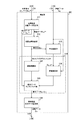
図2は、本技術の第1の実施の形態における携帯端末機100の一構成例を示すブロック図である。この携帯端末機100は、発光部110、制御部120、ToFセンサ200、固体撮像素子130、測距部300および距離データ処理部140を備える。
FIG. 2 is a block diagram showing a configuration example of the
発光部110は、周期的に明るさが変動する間欠光を発して物体に照射するものである。この発光部110は、例えば、矩形波の発光制御信号CLKpに同期して間欠光を発生する。また、例えば、発光部110として発光ダイオードが用いられ、間欠光として近赤外光などが用いられる。なお、発光制御信号CLKpは、周期信号であれば、矩形波に限定されない。例えば、発光制御信号CLKpは、サイン波であってもよい。
The
制御部120は、携帯端末機100全体を制御するものである。この制御部120は、発光制御信号CLKpを生成して発光部110およびToFセンサ200に信号線128を介して供給する。この発光制御信号CLKpの周波数は、例えば、20メガヘルツ(MHz)である。なお、発光制御信号CLKpの周波数は、20メガヘルツ(MHz)に限定されず、5メガヘルツ(MHz)などであってもよい。
The
また、制御部120は、発光制御信号CLKpより周波数の低い垂直同期信号VSYNCを生成してToFセンサ200および固体撮像素子130に信号線129を介して供給する。例えば、60ヘルツ(Hz)の周期信号が垂直同期信号VSYNCとして用いられる。なお、垂直同期信号VSYNCの周波数は、60ヘルツ(Hz)に限定されず、30ヘルツ(Hz)や120ヘルツ(Hz)であってもよい。
Further, the
ToFセンサ200は、物体の表面で反射した間欠光を光電変換するものである。このToFセンサ200には、複数の画素が二次元格子状に配置される。これらの画素は、物体表面で反射した間欠光を受光し、その受光量に応じた受光データを生成して測距部300に信号線209を介して供給する。それぞれの画素の受光データは、電荷信号Q1(u) obs、Q2(u) obs、Q3(u) obsおよびQ4(u) obsからなる。ここで、添え字のuは、ToFセンサ200における画素位置を示す。なお、ToFセンサ200は、特許請求の範囲に記載の間欠光受光部の一例である。また、ToFセンサ200における画素は、特許請求の範囲に記載の間欠光画素の一例である。
The
固体撮像素子130は、可視光や赤外光などの連続光を光電変換して画像データを生成するものである。この固体撮像素子130には、複数の画素が二次元格子状に配置される。また、固体撮像素子130の受光面の面積はToFセンサ200と同程度であり、また、画素数はToFセンサ200より多いものとする。すなわち、固体撮像素子130の画素密度(解像度)は、ToFセンサ200より高い。固体撮像素子130上の画素のそれぞれは、連続光を受光し、その連続光の受光量に応じた受光データを生成して測距部300に信号線139を介して供給する。それぞれの画素の受光データは、色情報を含まず、輝度データG(P)のみを含む。このため、これらの受光データからなる画像データは、モノクロ画像データとなる。また、添え字のPは、固体撮像素子130における画素位置を示す。なお、固体撮像素子130は、特許請求の範囲に記載の連続光受光部の一例である。また、固体撮像素子130における画素は、特許請求の範囲に記載の連続光画素である。
The solid-
測距部300は、ToFセンサ200からの電荷信号と固体撮像素子130からの輝度データとに基づいて物体までの距離(言い換えれば、デプス)を測定し、かつ、高解像度化するものである。この測距部300は、ToFセンサ200からの電荷信号を使用して、画素ごとの距離データを配列したデプスマップを生成する。前述したように、ToFセンサ200の画素数は、固体撮像素子130より少ないため、電荷信号から生成されたデプスマップの解像度は、モノクロ画像データよりも低い。
The
そして、測距部300は、モノクロ画像データを用いてデプスマップの解像度を高くする。測距部300は、解像度を向上させたデプスマップを距離データ処理部140に信号線309を介して供給する。
Then, the
距離データ処理部140は、デプスマップを用いて所定の処理を実行するものである。例えば、距離に応じた度合いのぼかし処理を行う画像処理や、距離に応じて物体を検出して物体のみを切り抜く処理などが実行される。
The distance
なお、発光部110、制御部120、ToFセンサ200、固体撮像素子130、測距部300および距離データ処理部140を同一の機器に設けているが、これらを複数の装置や機器に分散して配置してもよい。例えば、固体撮像素子130およびToFセンサ200を外部のセンサモジュールに配置し、残りをノート型パーソナルコンピュータやタブレット端末に配置してもよい。
The
[ToFセンサの構成例]
図3は、第1の実施の形態におけるToFセンサ200の一構成例を示すブロック図である。このToFセンサ200は、行走査回路210と、画素アレイ部220と、タイミング制御部240と、複数のAD(Analog to Digital)変換部250と、列走査回路260と信号処理部270とを備える。画素アレイ部220には、二次元格子状に複数の画素回路230が配置される。以下、所定の方向に配列された画素回路230の集合を「行」と称し、行に垂直な方向に配列された画素回路230の集合を「列」と称する。前述のAD変換部250は、列ごとに設けられる。
[Configuration example of ToF sensor]
FIG. 3 is a block diagram showing a configuration example of the
タイミング制御部240は、垂直同期信号VSYNCに同期して行走査回路210、AD変換部250および列走査回路260を制御するものである。
The
行走査回路210は、発光制御信号CLKpに同期して全行を同時に露光させ、露光終了後に行を順に選択して画素信号を出力させるものである。画素回路230は、行走査回路210の制御に従って反射光を受光し、受光量に応じた電荷信号を出力するものである。
The
AD変換部250は、対応する列からの電荷信号をAD変換するものである。このAD変換部250は、列走査回路260の制御に従って、AD変換した電荷信号を信号処理部270に出力する。列走査回路260は、AD変換部250を順に選択して電荷信号を出力させるものである。
The
信号処理部270は、電荷信号に対して、所定の信号処理を行うものである。この信号処理部270は、信号処理後の電荷信号を測距部300に供給する。
The
なお、ToFセンサ200には、実際には反射光を集光するためのレンズがさらに設けられるが、このレンズは図2において、記載の便宜上、省略されている。
The
[画素回路の構成例]
図4は、第1の実施の形態における画素回路230の回路の一例を示すブロック図である。この画素回路230は、受光素子231と、転送スイッチ232と、電荷蓄積部233および234と、選択スイッチ235および236とを備える。
[Pixel circuit configuration example]
FIG. 4 is a block diagram showing an example of the circuit of the
受光素子231は、光を光電変換して電荷を生成するものである。この受光素子231として、例えば、フォトダイオードが用いられる。
The
転送スイッチ232は、行走査回路210の制御に従って受光素子231を電荷蓄積部233、電荷蓄積部234およびリセット電源Vrstのいずれかに接続するものである。この転送スイッチ232は、例えば、複数のMOS(Metal-Oxide-Semiconductor)トランジスタなどにより実現される。
The
電荷蓄積部233および234は、電荷を蓄積して、その蓄積量に応じた電圧を生成するものである。これらの電荷蓄積部233および234として、例えば、浮遊拡散層が用いられる。
The electric
選択スイッチ235は、行走査回路210の制御に従って、電荷蓄積部233とAD変換部250との間の線路を開閉するものである。選択スイッチ236は、行走査回路210の制御に従って、電荷蓄積部234とAD変換部250との間の線路を開閉するものである。例えば、行走査回路210によりFD読出し信号RD_FD1が供給された際に選択スイッチ235が閉状態に遷移し、行走査回路210によりFD読出し信号RD_FD2が供給された際に選択スイッチ236が閉状態に遷移する。これらの選択スイッチ235および236のそれぞれは、例えば、MOSトランジスタなどにより実現される。
The
図5は、第1の実施の形態におけるQ1Q2検出期間内の画素の露光制御の一例を示すタイミングチャートである。間欠光の照射が開始されると画素回路230は、電荷信号Q1(u) obsおよびQ2(u) obsの生成と、電荷信号Q3(u) obsおよびQ4(u) obsの生成とを交互に繰り返し行う。以下、電荷信号Q1(u) obsおよびQ2(u) obsの検出期間を「Q1Q2検出期間」と称し、電荷信号Q3(u) obsおよびQ4(u) obsの検出期間を「Q3Q4検出期間」と称する。Q1Q2検出期間およびQ3Q4検出期間のそれぞれの長さは、垂直同期信号VSYNCの周期(例えば、1/60秒)である。また、Q1Q2検出期間およびQ3Q4検出期間からなる期間を以下、「測距期間」と称する。この測距期間は、垂直同期信号VSYNCの2周期分の期間(例えば、1/30秒)となる。
FIG. 5 is a timing chart showing an example of pixel exposure control within the Q1Q2 detection period according to the first embodiment. When the irradiation of intermittent light is started, the
ここで、電荷信号Q1(u) obs、は、間欠光の発光制御信号CLKpの特定の位相(例えば、立上り)を0度として、0度から180度までの受光量q1をQ1Q2検出期間に亘って累積したものである。発光制御信号CLKpの周波数は20メガヘルツ(MHz)と高いため、その1周期(1/20マイクロ秒)当たりの受光量は非常に少なく、検出が困難である。このため、画素回路230は、発光制御信号CLKpの周期(1/20マイクロ秒)より長い1/60秒などのQ1Q2検出期間に亘って、受光量q1のそれぞれを累積し、その総量を示す信号を電荷信号Q1(u) obs、として生成する。また、電荷信号Q2(u) obs、は、180度から360度までの反射光の受光量q2をQ1Q2検出期間に亘って累積したものである。
Here, the charge signal Q1 (u) obs sets the specific phase (for example, rising edge ) of the emission control signal CLKp of the intermittent light to 0 degrees, and sets the light receiving amount q1 from 0 degrees to 180 degrees over the Q1Q2 detection period. It is a cumulative total. Since the frequency of the light emission control signal CLKp is as high as 20 MHz (MHz), the amount of light received per cycle (1/20 microsecond) is very small, and detection is difficult. Therefore, the
また、電荷信号Q3(u) obs、は、90度から270度までの反射光の受光量q3をQ3Q4検出期間に亘って累積したものである。また、電荷信号Q4(u) obs、は、270度から90度までの反射光の受光量q4をQ3Q4検出期間に亘って累積したものである。 Further, the charge signal Q3 (u) obs is a cumulative amount of received light q3 of reflected light from 90 degrees to 270 degrees over the Q3Q4 detection period. Further, the charge signal Q4 (u) obs is a cumulative amount of received light q4 of reflected light from 270 degrees to 90 degrees over the Q3Q4 detection period.
これらの電荷信号Q1(u) obs、Q2(u) obs、Q3(u) obsおよびQ4(u) obsから、携帯端末機100は、物体までの距離を画素毎に算出することができる。
From these charge signals Q1 (u) obs , Q2 (u) obs , Q3 (u) obs and Q4 (u) obs , the
例えば、タイミングT1からタイミングT2までのQ1Q2検出期間において、その期間の電荷信号Q1(u) obsおよびQ2(u) obsが検出される。まず、行走査回路210は、タイミングT1から所定のパルス期間に亘ってリセット信号RSTを全行に供給する。このリセット信号RSTにより、全行の電荷蓄積部233および234の電荷蓄積量が初期化される。
For example, in the Q1Q2 detection period from timing T1 to timing T2, the charge signals Q1 (u) obs and Q2 (u) obs during that period are detected. First, the
そして、行走査回路210は、Q1Q2検出期間において、発光制御信号CLKpの周期内の0度から180度までに亘って全行についてハイレベルのFD選択信号SEL_FDにより受光素子231が生成した電荷を電荷蓄積部233に転送させる。この制御により、電荷蓄積部233に受光量q1が蓄積される。
Then, in the Q1Q2 detection period, the
また、行走査回路210は、Q1Q2検出期間において、発光制御信号CLKpの周期内の180度から360度までに亘って全行についてミドルレベルのFD選択信号SEL_FDにより受光素子231が生成した電荷を電荷蓄積部234に転送させる。この制御により、電荷蓄積部234に受光量q2が蓄積される。
Further, in the Q1Q2 detection period, the
そして、タイミングT2の直前のタイミングT11において行走査回路210は、1行目にFD読出し信号RD_FD1およびRD_FD2を順に供給する。この制御により、1行目の電荷信号Q1(u) obsおよびQ2(u) obsが読み出される。次に、行走査回路210は、2行目にFD読出し信号RD_FD1およびRD_FD2を順に供給して電荷信号を読み出す。以下、同様に行走査回路210は、行を順に選択して電荷信号を読み出す。
Then, at the timing T11 immediately before the timing T2, the
このように、Q1Q2検出期間において画素回路230のそれぞれは、0度から180度までの電荷信号Q1(u) obsと、180度から360度までの電荷信号Q2(u) obsとを生成する。
Thus, Q1Q2 each
図6は、第1の実施の形態におけるQ3Q4検出期間内の画素回路230の露光制御の一例を示すタイミングチャートである。例えば、タイミングT2からタイミングT3までのQ3Q4検出期間において、その期間の電荷信号Q3(u) obsおよびQ4(u) obsが生成される。まず、行走査回路210は、タイミングT2から所定のパルス期間に亘ってリセット信号RSTを全行に供給する。また、行走査回路210は、ローレベルのFD選択信号SEL_FDにより、全行の受光素子231の電荷を初期化する。
FIG. 6 is a timing chart showing an example of exposure control of the
そして、行走査回路210は、最初の0度から90度において、全行についてミドルレベルのFD選択信号SEL_FDにより受光素子231が生成した電荷を電荷蓄積部234に転送させる。この制御により、電荷蓄積部234に受光量q4が蓄積される。以降において行走査回路210は、発光制御信号CLKpの周期内の90度から270度までに亘って全行についてハイレベルのFD選択信号SEL_FDにより受光素子231が生成した電荷を電荷蓄積部233に転送させる。この制御により、電荷蓄積部233に受光量q3が蓄積される。
Then, the
また、行走査回路210は、Q3Q4検出期間において、発光制御信号CLKpの周期内の270度から90度までに亘って全行についてミドルレベルのFD選択信号SEL_FDにより受光素子231が生成した電荷を電荷蓄積部234に転送させる。この制御により、電荷蓄積部234に受光量q4が蓄積される。
Further, in the Q3Q4 detection period, the
そして、タイミングT3の直前のタイミングT21において行走査回路210は、1行目にFD読出し信号RD_FD1およびRD_FD2を順に供給する。この制御により、1行目の電荷信号Q3(u) obs、およびQ4(u) obsが読み出される。以下、同様に行走査回路210は、行を順に選択して電荷信号を読み出す。
Then, at the timing T21 immediately before the timing T3, the
このように、Q3Q4検出期間において画素回路230のそれぞれは、90度から270度までの電荷信号Q3(u) obs、と、270度から90度までの電荷信号Q4(u) obs、とを生成する。
In this way, during the Q3Q4 detection period, each of the
[固体撮像素子の構成例]
図7は、本技術の第1の実施の形態における固体撮像素子130の一構成例を示すブロック図である。この固体撮像素子130は、行走査回路131と、画素アレイ部132と、タイミング制御部135と、複数のAD変換部136と、列走査回路137と信号処理部138とを備える。また、画素アレイ部132には、複数の画素回路134が二次元格子状に配置される。この固体撮像素子130の画素密度は、前述したように、ToFセンサ200よりも高く、また、固体撮像素子130は、ToFセンサ200の近傍に設けられる。このToFセンサ200の1画素は、一定の角度範囲内の物体上の面までの平均的な距離を測距している。その1画素が測距する面は、固体撮像素子130上の複数の画素により撮像される。このため、ある物体表面の所定の反射位置で反射した間欠光が、ToFセンサ200上の1つの画素に入射する場合、その反射位置からの連続光は、固体撮像素子130上の複数の画素に入射される。このように、ToFセンサ200上の1画素に対応する複数の画素回路134からなる領域を以下、画素ブロック133と称する。
[Structure example of solid-state image sensor]
FIG. 7 is a block diagram showing a configuration example of the solid-
例えば、ToFセンサ200の総画素数をM(Mは整数)とし、ToFセンサ200上の1画素について、固体撮像素子130上のN(Nは2以上の整数)画素が対応する場合について考える。この場合、画素ブロック133の個数はM個となり、固体撮像素子130の総画素数は、N×Mとなる。固体撮像素子130においても所定の方向に配列された画素回路134の集合を「行」と称し、行に垂直な方向に配列された画素回路134の集合を「列」と称する。前述のAD変換部136は、列ごとに設けられる。
For example, consider a case where the total number of pixels of the
タイミング制御部135は、垂直同期信号VSYNCに同期して行走査回路131、AD変換部136および列走査回路137を制御するものである。
The
行走査回路131は、行のそれぞれを選択して輝度信号を出力させるものである。画素回路134は、行走査回路131の制御に従って連続光を受光し、受光量に応じた輝度信号を出力するものである。
The
AD変換部136は、対応する列からの輝度信号をAD変換するものである。このAD変換部136は、列走査回路137の制御に従って、AD変換した輝度信号を輝度データとして信号処理部138に出力する。列走査回路137は、AD変換部136を順に選択して輝度データを出力させるものである。
The
信号処理部138は、輝度データに対して、CDS処理などの信号処理を行うものである。この信号処理部138は、信号処理後の輝度データを測距部300に供給する。
The
前述したように、ToFセンサ200の測距期間は、垂直同期信号VSYNCの2周期分である。ToFセンサ200の動作に合わせて、固体撮像素子130も、この測距期間(2周期)ごとに1枚のモノクロ画像データを生成するものとする。
As described above, the distance measuring period of the
図8は、本技術の第1の実施の形態における固体撮像素子130とToFセンサ200とのそれぞれの投影面上の画素の位置関係の一例を示す図である。
FIG. 8 is a diagram showing an example of the positional relationship of the pixels on the projection planes of the solid-
ToFセンサ200の光軸中心を原点とした座標系を(Xt、Yt、Zt)とし、固体撮像素子130の光軸中心を原点とした座標系を(Xc、Yc、Zc)とする。これらの座標系の一方から他方への変換は、3行3列の回転行列Rと、3次元の並進ベクトルTとにより行われるものとする。これらの回転行列Rおよび並進ベクトルTは、既知の値であり、固体撮像素子130とToFセンサ200とのそれぞれの光学系の位置関係により一意に決定される。
The coordinate system with the center of the optical axis of the
ここで、ToFセンサ200に付随するレンズの焦点距離をFtとすると、ToFセンサ200の投影面上のZt座標の値は、既知のFtとなる。そして、(0、0、Ft)tが、ToFセンサ200の投影面の座標系(Utx、Uty)の原点となる。Xt軸とUtx軸とは平行である。また、Yt軸とUty軸とが平行である。
Here, assuming that the focal length of the lens attached to the
また、固体撮像素子130に付随するレンズの焦点距離をFcとすると、固体撮像素子130の投影面上のZc座標の値は、既知のFcとなる。そして、(0、0、Fc)tが、固体撮像素子130の投影面の座標系(Ucx、Ucy)の原点となる。Xc軸とUcx軸とは平行である。また、Yc軸とUcy軸とが平行である。
Further, assuming that the focal length of the lens attached to the solid-
ToFセンサ200の投影面上の位置521に着目すると、この位置521(すなわち、画素位置U)は、二次元平面上の座標を用いて次の式により表されるとする。

ToFセンサ200に対応する座標系(Xt、Yt、Zt)において、位置521に投影されている物体表面の反射点522への方向は、式1より(Ux、Uy、Ft)tで表すことができる。ここで、上付きのtは、転置を意味する。ToFセンサ200の光軸中心から反射点522までの距離をD(U)が測距された場合、その距離データD(U)と方向(Ux、Uy、Ft)tとに基づいて、反射点522の3次元位置Prを次の式により表すことができる。
固体撮像素子130に対応する座標系において、式2の示す位置は、回転行列Rおよび並進ベクトルTを用いて次の式により表すことができる。
反射点522が、固体撮像素子130の投影面に投影される位置523の2次元位置Ppは、その投影面の座標系(Ucx、Ucy)において、次の式により表すことができる。
まとめると、ToFセンサ200の投影面上の位置521(画素位置U)に投影されている物体は、固体撮像素子130の投影面においては式4の位置523に投影される。ただし、式4の右辺の座標は、式3により定義される。
In summary, the object projected at the position 521 (pixel position U) on the projection surface of the
次に、ToFセンサ200の1つの画素が、固体撮像素子130のいくつの画素に対応するかについて考える。ある画素と、その隣接画素では、焦点距離の逆数だけ異なる角度を撮像または測距することになる。したがって、ToFセンサ200の1画素により測距される範囲は、縦方向について固体撮像素子130が撮像する範囲の「Fc/Ft」倍である。横方向についても同様である。すなわち、ToFセンサ200の1画素が測距する範囲は、固体撮像素子130の一辺がFc/Ft画素の矩形の領域である。ここで、ToFセンサ200よりも固体撮像素子130の方が解像度が高いため、FcはFtより大きい。
Next, consider how many pixels of the solid-
上述の関係に基づいて測距部300は、ToF200が生成した距離データをアップサンプリングする。ここで、ToFセンサ200上に、長さが1の複数の正方格子を想定し、それらの正方格子ごとに測距データが生成されるものと考える。この場合、アップサンプリングにより、長さが「Ft/Fc」の正方格子ごとに距離データが生成される。長さが1の正方格子の位置の集合をLとし、アップサンプリング前の画素位置uは次の式により表される。
また、長さが「Ft/Fc」の正方格子の位置の集合をHとすると、アップサンプリング後の画素位置Uは、次の式により表される。
[測距部の構成例]
図9は、本技術の第1の実施の形態における測距部300の一構成例を示すブロック図である。この測距部300は、低解像度距離データ生成部311、投影位置供給部312、平均演算部313、および、クロスバイラテラルフィルタ314を備える。
[Configuration example of distance measuring unit]
FIG. 9 is a block diagram showing a configuration example of the ranging
低解像度距離データ生成部311は、電荷信号に基づいてToFセンサ200の画素ごとに距離データD(u) obsを生成するものである。この距離データD(u) obsは、例えば、次の式により求められる。
ここで、式9において距離データD(u) obsの単位は、例えば、メートル(m)である。cは光速であり、単位は、例えば、メートル毎秒(m/s)である。arctan()は、正接関数の逆関数を示す。式7乃至式9におけるI(u) obsおよびQ(u) obsは、電荷信号の差分データである。 Here, in Equation 9, the unit of the distance data D (u) obs is, for example, meters (m). c is the speed of light, and the unit is, for example, meters per second (m / s). arctan () indicates the inverse function of the tangent function. I (u) obs and Q (u) obs in Equations 7 to 9 are difference data of charge signals.
低解像度距離データ生成部311は、生成した距離データD(u) obsを低解像度距離データとして投影位置供給部312とクロスバイラテラルフィルタ314とに供給する。
The low-resolution distance
投影位置供給部312は、ToFセンサ200上の画素位置uに対応する、固体撮像素子130上の投影位置p(u)を演算するものである。
The projection
投影位置供給部312は、画素位置uのX座標uxおよびY座標uyを取得し、次の式により投影位置p(u)を求める。
この式10の右辺におけるX(u)、Y(u)およびZ(u)は、次の式により表される。
式10および式11により演算された投影位置p(u)を中心とし、一辺の長さがFc/Ftの正方形の領域が画素ブロック133に該当する。投影位置供給部312は、この投影位置p(u)をクロスバイラテラルフィルタ314および平均演算部313に供給する。
A square region having a side length of Fc / Ft centered on the projection position p (u) calculated by the equations 10 and 11 corresponds to the
平均演算部313は、画素ブロック133ごとに、輝度データG(P)の平均値を演算するものである。この平均演算部313は、投影位置p(u)ごとに、次の式により平均データG(p(u)) avgを演算する。
平均演算部313は、式12により演算した平均データG(p(u)) avgをクロスバイラテラルフィルタ314に供給する。
The
クロスバイラテラルフィルタ314は、関数演算部315および316と、距離データアップサンプリング部317とを備える。
The
関数演算部315は、画素ブロック133内の画素位置Pと、投影位置p(u)との間のユークリッド距離をガウス関数h()に入力して、そのユークリッド距離が大きいほど小さな重みを演算するものである。この関数演算部315は、演算結果h()を距離データアップサンプリング部317に供給する。
The
関数演算部316は、画素ブロック133内の輝度データG(P)と、平均データG(p(u)) avgとの差分絶対値をガウス関数g()に入力して、その差分絶対値が大きいほど小さな重みを演算するものである。この関数演算部316は、演算結果g()を距離データアップサンプリング部317に供給する。
The
距離データアップサンプリング部317は、次の式により、低解像度距離データD(u) obsをアップサンプリングするものである。ここで、添え字P付のオメガは、白黒イメージセンサ200上の位置Pの近傍の画素位置の集合を示している。
距離データアップサンプリング部317は、式13および式14を用いて演算した距離データD(P)を高解像度距離データとして距離データ処理部140に供給する。
The distance
なお、測距部300は、クロスバイラテラルフィルタ314によりアップサンプリングを行っているが、アップサンプリングを行うことができるものであれば、用いるフィルタはクロスバイラテラルフィルタ314に限定されない。
The ranging
図10は、本技術の第1の実施の形態における固体撮像素子130が受光する連続光の光線とToFセンサ200が受光する間欠光の光線との関係の一例を示す図である。同図において、点線は連続光の光線を示し、実線は、間欠光の光線を示す。
FIG. 10 is a diagram showing an example of the relationship between the continuous light ray received by the solid-
前述したように固体撮像素子130の画素密度は、ToFセンサ200よりも高く、また、固体撮像素子130は、ToFセンサ200の近傍に設けられる。このToFセンサ200の1画素は、一定の角度範囲内の物体上の面(例えば、光線511を中心とした物体上の面)までの平均的な距離を測距している。その1画素が測距する面は、固体撮像素子130上の複数の画素により撮像される。例えば、ある反射位置で反射した反射光の光線511がToFセンサ200上の1つの画素に入射される場合、その反射位置からの連続光の光線501、502、503、504および505は、固体撮像素子130上の互いに異なる画素に入射される。したがって、間欠光の光線511により測定された距離は、連続光501、502、503、504および505のそれぞれに対応する画素までの各距離の平均値となる。
As described above, the pixel density of the solid-
図11は、本技術の第1の実施の形態におけるToFセンサ200の画素毎の測距範囲の一例を示す図である。同図における実線は、間欠光の光線を示す。また、両端が矢印の弧は、ToFセンサ200上の1画素に入射される間欠光の範囲を示す。このToFセンサ200の1画素には、実線を中心とする一定の角度範囲の間欠光が入射される。そして、ToFセンサ200は、画素毎に、その角度範囲内の物体上の面までの平均的な距離を測定する。
FIG. 11 is a diagram showing an example of a distance measuring range for each pixel of the
図12は、本技術の第1の実施の形態における画素ごとの距離データおよび輝度データの一例を示す図である。同図におけるaは、画素ごとの低解像度の距離データD(u) obsの一例を示す図である。同図のaにおいて、縦軸は距離データD(u) obsの値を示し、横軸はToFセンサ200上の画素位置uを示す。画素位置u1、u2、u3およびu4などにおいて、距離データD(u) obsが測定される。
FIG. 12 is a diagram showing an example of distance data and luminance data for each pixel in the first embodiment of the present technology. In the figure, a is a diagram showing an example of low-resolution distance data D (u) obs for each pixel. In a of the figure, the vertical axis represents the value of the distance data D (u) obs , and the horizontal axis represents the pixel position u on the
図12におけるbは、画素ごとの輝度データG(P)の一例を示す図である。同図のbにおいて、縦軸は輝度データG(P)の値を示し、横軸は固体撮像素子130上の画素位置Pを示す。画素位置u1やu2などの画素位置uごとに、複数の輝度データG(P)が対応付けられる。
FIG. 12B is a diagram showing an example of the luminance data G (P) for each pixel. In b of the figure, the vertical axis represents the value of the luminance data G (P) , and the horizontal axis represents the pixel position P on the solid-
図12におけるcは、画素ごとの高解像度の距離データD(p)の一例を示す図である。同図のcにおいて、縦軸は距離データD(P)の値を示し、横軸は固体撮像素子130上の画素位置Pを示す。式13および式14に例示したクロスバイラテラルフィルタにより、距離データがアップサンプリングされ、画素位置Pごとに距離データD(p)が算出される。
FIG. 12C is a diagram showing an example of high-resolution distance data D (p) for each pixel. In c of the figure, the vertical axis represents the value of the distance data D (P) , and the horizontal axis represents the pixel position P on the solid-
図12におけるdは、ToFセンサ200の1画素が、一定の面積の物体上の面でなく、物体上の一点までの距離をピンポイントで測距するものと想定する比較例の輝度データの一例を示す図である。同図のbにおいて、縦軸は輝度データの値を示し、横軸は固体撮像素子上の画素位置Pを示す。この比較例では、図12におけるbと異なり、ToFセンサの画素ごとに、1つの輝度データが対応付けられる。
In FIG. 12, d is an example of luminance data of a comparative example in which one pixel of the
前述したようにToFセンサ200の実際の画素は、ある程度の大きさを持っている。従って、ToFセンサ200の各画素が測距する物体表面の位置はピンポイントではなく、ある面積を持った領域の平均的な距離を測定していることになる。このため、図12におけるdの比較例では、正確なアップサンプリングを行うことができない。これに対して、図12におけるbでは、ToFセンサ200の画素ごとに、その画素が測距する面に係る複数の輝度データを対応づけている。このため、それらの輝度データの平均を演算することにより、携帯端末機100は、比較例よりも正確にアップサンプリングを行うことができる。
As described above, the actual pixels of the
図13は、本技術の第1の実施の形態におけるフィルタ処理の一例を示す図である。携帯端末機100は、ToFセンサ200上の画素ごとに、低解像度距離データD(u) obsを生成し、固体撮像素子130の画素ごとに輝度データG(P)を生成する。ToFセンサ200の解像度は、固体撮像素子130より低く、ToFセンサ200の1画素について、固体撮像素子130上の複数の画素からなる画素ブロックが対応付けられる。例えば、ToFセンサ200の画素11と、固体撮像素子130上の画素00、01、02、10、11、12、20、21および22からなる画素ブロックとが対応付けられる。
FIG. 13 is a diagram showing an example of filtering processing in the first embodiment of the present technology. The
携帯端末機100は、画素ブロックごとに輝度データの平均値を算出する。例えば、画素00、01、02、10、11、12、20、21および22の輝度データが「22」、「21」、「22」、「19」、「20」、「18」、「23」、「21」および「23」である場合、それらの平均値として「21」が算出される。
The
クロスバイラテラルフィルタ314において、画素位置Pの輝度データと画素ブロックの平均値との差分絶対値がガウス関数g()に入力される。そして、そのガウス関数g()と、ガウス関数h()とが低解像度距離データG(u) obsに乗算されて、画素位置Pごとの距離データD(p)が出力される。
In the
[携帯端末機の動作例]
図14は、本技術の第1の実施の形態における携帯端末機の動作の一例を示すフローチャートである。この動作は、例えば、デプスマップを用いるアプリケーションが実行されたときに開始される。ToFセンサ200は、画素ごとに電荷信号Q1(u) obs乃至Q4(u) obsを生成する(ステップS901)。また、固体撮像素子130は、画素ごとに輝度データG(P)を生成する(ステップS902)。
[Operation example of mobile terminal]
FIG. 14 is a flowchart showing an example of the operation of the mobile terminal according to the first embodiment of the present technology. This operation is started, for example, when an application using the depth map is executed. The
そして、測距部300は、高解像度のデプスマップを生成するための測距処理を実行する(ステップS910)。距離データ処理部140は、デプスマップにおける距離データD(P)を処理する(ステップS903)。
Then, the
携帯端末機100は、アプリケーションの終了などにより測距を終了するか否かを判断する(ステップS903)。測距を終了しない場合に(ステップS903:No)、携帯端末機100は、ステップS901以降を繰り返し実行する。一方、測距を終了する場合に(ステップS903:Yes)、携帯端末機100は、デプスマップを生成するための動作を終了する。
The
図15は、本技術の第1の実施の形態における測距処理の一例を示すフローチャートである。測距部300は、電荷信号Q1(u) obs乃至Q4(u) obsから、低解像度の距離データD(u) obsを生成し(ステップS911)、画素位置uごとに投影位置p(u)を演算する(ステップS912)。また、測距部300は、画素ブロックごとに平均データG(p(u)) avgを演算する(ステップS913)。そして、測距部300は、クロスバイラテラルフィルタにより、距離データD(u) obsをアップサンプリングする(ステップS914)。ステップS914の後に測距部300は、測距処理を終了する。
FIG. 15 is a flowchart showing an example of distance measurement processing according to the first embodiment of the present technology. The ranging
このように、本技術の第1の実施の形態によれば、画素ブロック内の輝度の平均データを低解像度の距離データとともにフィルタに入力するため、その平均データを基準値として高解像度の距離データを演算することができる。これにより、アップサンプリングを正確に行うことができる。 As described above, according to the first embodiment of the present technology, since the average data of the brightness in the pixel block is input to the filter together with the low resolution distance data, the high resolution distance data using the average data as a reference value. Can be calculated. As a result, upsampling can be performed accurately.
<2.第2の実施の形態>
上述の第1の実施の形態では、距離データをアップサンプリングしていたが、その代わりに式7および式8における差分データをアップサンプリングすることもできる。この第2の実施の形態の携帯端末機100は、差分データをアップサンプリングする点において第1の実施の形態と異なる。
<2. Second Embodiment>
In the first embodiment described above, the distance data is upsampled, but instead, the difference data in the equations 7 and 8 can be upsampled. The
図16は、本技術の第2の実施の形態における測距部300の一構成例を示すブロック図である。この第2の実施の形態の測距部300は、距離データアップサンプリング部317の代わりに差分データアップサンプリング部323を備え、高解像度差分データ変換部324をさらに備える点において第1の実施の形態と異なる。
FIG. 16 is a block diagram showing a configuration example of the ranging
第2の実施の形態の低解像度距離データ生成部311は、画素毎に低解像度距離データD(u) obsに加えて、差分データI(u) obsおよびQ(u) obsをさらに生成してクロスバイラテラルフィルタ314に供給する。
The low-resolution distance
差分データアップサンプリング部323は、次の式により差分データI(u) obsおよびQ(u) obsをアップサンプリングするものである。
差分データアップサンプリング部323は、式15および式16により演算した差分データI(P)およびQ(P)を高解像度差分データとして高解像度差分データ変換部324に供給する。
The difference
高解像度差分データ変換部324は、次の式により、高解像度差分データI(P)およびQ(P)を高解像度距離データD(P)に変換して距離データ処理部140に出力するものである。
図17は、本技術の第2の実施の形態における測距処理の一例を示すフローチャートである。この第2の実施の形態の測距処理は、ステップS911およびS914の代わりにステップS921およびS924を実行し、ステップS925をさらに実行する点において第1の実施の形態と異なる。 FIG. 17 is a flowchart showing an example of distance measuring processing according to the second embodiment of the present technology. The distance measuring process of the second embodiment is different from that of the first embodiment in that steps S921 and S924 are executed instead of steps S911 and S914, and step S925 is further executed.
測距部300は、画素位置uごとに差分データI(u) obsおよびQ(u) obsを生成し(ステップS921)、ステップS912およびS913を実行する。そして、測距部300は、クロスバイラテラルフィルタにより、差分データI(u) obsおよびQ(u) obsをアップサンプリングする(ステップS924)。測距部300は、アップサンプリング後の差分データを高解像度距離データD(P)に変換し(ステップS925)、測距処理を終了する。
The
なお、第1および第2の実施の形態において固体撮像素子130は、モノクロ画像データを生成しているが、モノクロ画像データの代わりにカラー画像データを生成してもよい。この場合、例えば、クロスバイラテラルフィルタの式12乃至式16の輝度データG(P)および平均データG(p(u)) avgは、R(Red)、G(Green)およびB(Blue)の3次元ベクトルとなる。また、式13乃至式16における、ガウス関数g()への入力値は、R、GおよびBの3次元ベクトル上の2点間の距離となる。
Although the solid-
このように、本技術の第2の実施の形態では、画素ブロック内の輝度の平均データを低解像度の差分データとともにフィルタに入力するため、その平均データを基準値として高解像度の差分データを演算することができる。これにより、アップサンプリングを正確に行うことができる。 As described above, in the second embodiment of the present technology, since the average brightness data in the pixel block is input to the filter together with the low resolution difference data, the high resolution difference data is calculated using the average data as a reference value. can do. As a result, upsampling can be performed accurately.
<3.第3の実施の形態>
上述の第1の実施の形態では、携帯端末機100は、クロスバイラテラルフィルタ314を用いて、距離データをアップサンプリングしていた。しかし、携帯端末機100は、クロスバイラテラルフィルタ314を用いずに距離データをアップサンプリングすることもできる。例えば、携帯端末機100は、距離データと平均データとの間の関係を示す関数を回帰分析により求めて、その関数を用いて距離データをアップサンプリングしてもよい。この第3の実施の形態の携帯端末機100は、回帰分析により求めた関数を用いて距離データをアップサンプリングする点において第1の実施の形態と異なる。
<3. Third Embodiment>
In the first embodiment described above, the
図18は、本技術の第3の実施の形態における測距部300の一構成例を示すブロック図である。この第3の実施の形態の測距部300は、クロスバイラテラルフィルタ314の代わりに、回帰分析部331および高解像度距離データ生成部332を備える点において第1の実施の形態と異なる。
FIG. 18 is a block diagram showing a configuration example of the ranging
回帰分析部331は、距離データDと輝度データGとの関係を示す関数f()を回帰分析により求めるものである。この関数f()は、例えば、次の式により表される。
D=f(G)=a×G+b ・・・式18
上式において、aおよびbは実数の係数である。
The
D = f (G) = a × G + b ・ ・ ・ Equation 18
In the above equation, a and b are real coefficients.
回帰分析部331は、例えば、輝度データの平均データG(p(u)) avgを式18に入力した結果と、低解像度距離データD(u) obsとの差分の二乗和が最小になるときの係数aおよびbを求める最小二乗法を用いて回帰分析を行う。そして、回帰分析部331は、求めた係数aおよびbを回帰直線係数として高解像度距離データ生成部332に供給する。
For example, when the
高解像度距離データ生成部332は、式18に、各画素位置Pの輝度データG(P)を入力して高解像度距離データD(P)を生成し、距離データ処理部140に出力するものである。
The high-resolution distance
図19は、本技術の第3の実施の形態における輝度データと距離データとの関係の一例を示すグラフである。同図において縦軸は、輝度データGであり、横軸は距離データDである。また、黒丸は、対応する低解像度距離データD(u) obsと平均データG(p(u)) avgとの組合せのそれぞれをプロットしたものである。白丸は、高解像度の固体撮像素子130の画素位置Pにおける距離データD(P)と対応する高解像度輝度データG(P)の組をプロットしたものである。また、回帰直線531は、式18により表される直線である。
FIG. 19 is a graph showing an example of the relationship between the luminance data and the distance data in the third embodiment of the present technology. In the figure, the vertical axis is the luminance data G and the horizontal axis is the distance data D. The black circles are plots of each combination of the corresponding low-resolution distance data D (u) obs and the average data G (p (u)) avg . The white circles are plots of a set of distance data D (P) and corresponding high-resolution luminance data G (P) at the pixel position P of the high-resolution solid-
回帰分析部331は、固体撮像素子130上の着目した画素位置Pについて、p(u)がその近傍内にあるというuに関して、距離データD(u) obsと平均データG(p(u)) avgとの組合せを2次元空間上にプロットする。そして、回帰分析部331は、プロットした黒丸の集合に対して回帰分析を行い、回帰直線531を求める。高解像度距離データ生成部332は、得られた回帰直線531において、輝度データG(P)に対応する距離データを高解像度距離データD(P)として演算する。
The
図20は、本技術の第3の実施の形態における測距処理の一例を示すフローチャートである。この第3の実施の形態の測距処理は、ステップS914の代わりにステップS934およびS935を実行する点において第1の実施の形態と異なる。 FIG. 20 is a flowchart showing an example of distance measuring processing according to the third embodiment of the present technology. The distance measuring process of the third embodiment is different from that of the first embodiment in that steps S934 and S935 are executed instead of step S914.
測距部300は、ステップS911乃至S913を実行した後に、低解像度距離データD(u) obsと平均データG(p(u)) avgとに対して回帰分析を行い、回帰直線を求める(ステップS934)。そして、高解像度距離データ生成部332は、その回帰直線により、距離データをアップサンプリングし(ステップS935)、測距処理を終了する。
After executing steps S911 to S913, the
このように、本技術の第3の実施の形態では、携帯端末機100は、平均データと低解像度の距離データとを回帰分析して、それらの関係を示す関数を求めるため、その関数を用いて距離データを高い精度でアップサンプリングすることができる。
As described above, in the third embodiment of the present technology, the
<4.第4の実施の形態>
上述の第3の実施の形態では、回帰直線を用いて距離データをアップサンプリングしていたが、その代わりに式7および式8における差分データをアップサンプリングすることもできる。この第4の実施の形態の携帯端末機100は、回帰直線を用いて差分データをアップサンプリングする点において第3の実施の形態と異なる。
<4. Fourth Embodiment>
In the third embodiment described above, the distance data is upsampled using the regression line, but the difference data in the equations 7 and 8 can be upsampled instead. The
図21は、本技術の第4の実施の形態における測距部300の一構成例を示すブロック図である。この第4の実施の形態の測距部300は、回帰分析部331および高解像度距離データ生成部332の代わりに回帰分析部341および高解像度差分データ生成部342を備え、高解像度差分データ変換部324をさらに備える点で第3の実施の形態と異なる。高解像度差分データ変換部324の構成は、第2の実施の形態と同様である。
FIG. 21 is a block diagram showing a configuration example of the ranging
第4の実施の形態の低解像度距離データ生成部311は、画素毎に低解像度距離データD(u) obsに加えて、差分データI(u) obsおよびQ(u) obsをさらに生成して回帰分析部341に供給する。
The low-resolution distance
回帰分析部341は、差分データIおよびQと輝度データGとの関係を示す関数を回帰分析により求めるものである。この関数は、例えば、次の式により表される。
(I−I0)/c=(Q−Q0)/d=(G−G0)/e・・・式19
上式において、c、d、e、I0、Q0およびG0は実数の係数である。
The
(I-I 0 ) / c = (Q-Q 0 ) / d = (G-G 0 ) / e ... Equation 19
In the above equation, c, d, e, I 0 , Q 0 and G 0 are real coefficients.
そして、回帰分析部341は、求めた係数c、d、e、I0、Q0およびG0を回帰直線係数として高解像度差分データ生成部342に供給する。
Then, the
高解像度差分データ生成部342は、式19に、各画素位置Pの輝度データG(P)を入力して高解像度差分データI(P)およびQ(P)を生成し、高解像度差分データ変換部324に出力するものである。
The high-resolution difference
図22は、本技術の第4の実施の形態における輝度データと差分データとの関係の一例を示すグラフである。同図において直交する3軸の1つは、輝度データGを示し、残りの2つは差分データIおよびQを示す。また、黒丸は、対応する低解像度差分データI(u) obsおよびQ(u) obsと平均データG(p(u)) avgとの組合せのそれぞれをプロットしたものである。白丸は、高解像度の固体撮像素子130の画素位置Pにおける輝度データG(P)と対応する高解像度差分データI(P)およびQ(P)の組をプロットしたものである。また、回帰直線532は、式19により表される直線である。
FIG. 22 is a graph showing an example of the relationship between the luminance data and the difference data in the fourth embodiment of the present technology. In the figure, one of the three orthogonal axes shows the luminance data G, and the other two show the difference data I and Q. The black circles are plots of the combinations of the corresponding low-resolution difference data I (u) obs and Q (u) obs and the average data G (p (u)) avg . The white circles are plots of a set of high-resolution difference data I (P) and Q (P) corresponding to the luminance data G (P) at the pixel position P of the high-resolution solid-
回帰分析部341は、固体撮像素子130上の着目した画素位置Pについて、p(u)がその近傍内にあるというuに関して、差分データI(u) obsおよびQ(u) obsと平均データG(p(u)) avgとの組合せを3次元空間上にプロットする。そして、回帰分析部341は、プロットした黒丸の集合に対して回帰分析を行い、回帰直線532を求める。高解像度差分データ生成部342は、得られた回帰直線532において、輝度データG(P)に対応する差分データを高解像度距離データI(P)およびQ(P)として演算する。
The
図23は、本技術の第4の実施の形態における測距処理の一例を示すフローチャートである。この第4の実施の形態の測距処理は、ステップS911の代わりにステップS921を実行し、ステップS934およびS935の代わりにステップS944およびS945を実行し、ステップS925をさらに実行する点において第3の実施の形態と異なる。 FIG. 23 is a flowchart showing an example of distance measuring processing according to the fourth embodiment of the present technology. The distance measuring process of the fourth embodiment is the third in that step S921 is executed instead of step S911, steps S944 and S945 are executed instead of steps S934 and S935, and step S925 is further executed. Different from the embodiment.
測距部300は、画素ごとに差分データI(u) obsおよびQ(u) obsを生成し(ステップS921)、ステップS912およびS913を実行する。測距部300は、低解像度差分データI(u) obsおよびQ(u) obsと平均データG(p(u)) avgとに対して回帰分析を行い、回帰直線を求める(ステップS944)。そして、高解像度距離データ生成部332は、その回帰直線により、差分データをアップサンプリングする(ステップS945)。測距部300は、アップサンプリング後の差分データを高解像度距離データD(P)に変換し(ステップS925)、測距処理を終了する。
The
このように、本技術の第4の実施の形態では、携帯端末機100は、平均データと低解像度の差分データとを回帰分析して、それらの関係を示す関数を求めるため、その関数を用いて差分データを高い精度でアップサンプリングすることができる。
As described above, in the fourth embodiment of the present technology, the
<5.第5の実施の形態>
上述の第1の実施の形態では、携帯端末機100は、クロスバイラテラルフィルタ314を用いて、距離データをアップサンプリングしていた。しかし、携帯端末機100は、クロスバイラテラルフィルタ314を用いずに距離データをアップサンプリングすることもできる。例えば、携帯端末機100は、エネルギー最小化計算により、距離データをアップサンプリングしてもよい。この第5の実施の形態の携帯端末機100は、エネルギー最小化計算により距離データをアップサンプリングする点において第1の実施の形態と異なる。
<5. Fifth Embodiment>
In the first embodiment described above, the
図24は、本技術の第5の実施の形態における測距部300の一構成例を示すブロック図である。この第5の実施の形態の測距部300は、投影位置供給部312、平均演算部313およびクロスバイラテラルフィルタ314の代わりにエネルギー最小化計算部351を備える点において第1の実施の形態と異なる。
FIG. 24 is a block diagram showing a configuration example of the ranging
エネルギー最小化計算部351は、画素ブロックごとに高解像度距離データの平均値と低解像度距離データとの差を最小にするエネルギー最小化計算により高解像度距離データを生成するものである。このエネルギー最小化計算部351は、次の式を満たす高解像度距離データD(U)を求める。
式20の右辺の第1項はデータ項であり、第2項はスムーズ項である。式21における添え字u付の集合オメガは、ToFセンサ200上の画素位置uを中心とした、一辺の長さが1の正方領域内の画素位置の集合である。式23におけるn(u)は、画素位置uにおける勾配の方向を示す単位ベクトルであり、m(u)は、n(u)に直交する単位ベクトルである。また、式22および式23における関数T1/2は、非等方性拡散テンソルである。この非等方性拡散テンソルについては、「D. Ferstl, Image Guided Depth Upsampling Using Anisotropic Total Generalized Variation, ICCV 2013」に記載されている。式20および式23におけるA、Bおよびrは、所望の定数である。
The first term on the right side of Equation 20 is a data term, and the second term is a smooth term. The set omega with the subscript u in the formula 21 is a set of pixel positions in a square region having a side length of 1 centered on the pixel position u on the
式23のG(U)は、白黒イメージセンサ200上の次の式で示される位置における輝度データである。
この式24における座標X'(u)、Y'(u)およびZ'(u)は、次の式により表される。
式20のデータ項dTermは、式21に例示するように、低解像度距離データD(u) obsと、対応する画素ブロック内の高解像度距離データD(U)の平均値との差の二乗和を示す。エネルギー最小化計算部351は、そのデータ項が最小になるときの高解像度距離データD(U)を演算して距離データ処理部140に供給する。すなわち、低解像度距離データD(u) obsと、対応する画素ブロック内の高解像度距離データD(U)の平均値との差が最小になるときの高解像度距離データD(U)が演算される。また、式22のスムーズ項sTermにより、ToFセンサ200上の各位置uに対応する固体撮像素子130上の位置における輝度データG(U)に段差がない場合には、同様に距離データD(U)もなるべくスムーズになるように演算される。
The data term dTerm of Equation 20 is the sum of the squares of the differences between the low resolution distance data D (u) obs and the mean value of the high resolution distance data D (U) in the corresponding pixel block, as illustrated in Equation 21. Is shown. The energy
このように、第1乃至第4の実施の形態と同様に、第5の実施の形態においても、低解像度距離データG(u) obsは、対応する画素ブロック内の複数の画素のそれぞれの距離の平均を示すことを想定して演算を行っている。 As described above, as in the first to fourth embodiments, in the fifth embodiment, the low resolution distance data G (u) obs is the distance between each of the plurality of pixels in the corresponding pixel block. The calculation is performed on the assumption that the average of is shown.
図25は、本技術の第5の実施の形態における測距処理の一例を示すフローチャートである。この第5の実施の形態の測距処理は、ステップS912乃至S914の代わりにステップS952を実行する点において第1の実施の形態と異なる。 FIG. 25 is a flowchart showing an example of distance measuring processing according to the fifth embodiment of the present technology. The distance measuring process of the fifth embodiment is different from that of the first embodiment in that step S952 is executed instead of steps S912 to S914.
測距部300は、電荷信号Q1(u) obs乃至Q4(u) obsから、低解像度の距離データD(u) obsを生成する(ステップS911)。そして、測距部300は、エネルギー最小化計算により、距離データをアップサンプリングする(ステップS952)。
The ranging
このように、本技術の第5の実施の形態では、画素ブロックごとに高解像度距離データの平均値と低解像度距離データとの差を最小にするエネルギー最小化計算を行うため、フィルタを用いずに距離データをアップサンプリングすることができる。 As described above, in the fifth embodiment of the present technology, since the energy minimization calculation that minimizes the difference between the average value of the high resolution distance data and the low resolution distance data is performed for each pixel block, no filter is used. Distance data can be upsampled to.
<6.第6の実施の形態>
上述の第5の実施の形態では、距離データをアップサンプリングしていたが、その代わりに式7および式8における差分データをアップサンプリングすることもできる。この第6の実施の形態の携帯端末機100は、差分データをアップサンプリングする点において第5の実施の形態と異なる。
<6. 6th Embodiment>
In the fifth embodiment described above, the distance data is upsampled, but instead, the difference data in the equations 7 and 8 can be upsampled. The
図26は、本技術の第6の実施の形態における測距部300の一構成例を示すブロック図である。この第6の実施の形態の測距部300は、低解像度距離データ生成部311の代わりに低解像度差分データ生成部361を備える点において第5の実施の形態と異なる。また、第6の実施の形態の測距部300は、エネルギー最小化計算部351の代わりにエネルギー最小化計算部362を備え、高解像度差分データ変換部324をさらに備える点においても第5の実施の形態と異なる。高解像度差分データ変換部324の構成は、第2の実施の形態と同様である。
FIG. 26 is a block diagram showing a configuration example of the ranging
低解像度差分データ生成部361は、式8および式9により、画素ごとに差分データI(u) obsおよびQ(u) obsを生成してエネルギー最小化計算部362に供給するものである。
The low-resolution difference
エネルギー最小化計算部362は、画素ブロックごとに高解像度差分データの平均値と低解像度差分データとの差を最小にするエネルギー最小化計算により高解像度差分データを生成するものである。このエネルギー最小化計算部362は、次の式を満たす高解像度差分データI(U)およびQ(U)を求める。
ここで、画素位置Uは、式24および式25と次の式とにより表される。
式26乃至式29により、低解像度差分データI(u) obsおよびQ(u) obsと、対応する画素ブロック内の高解像度差分データI(U)およびQ(U)の平均値との差が最小になるときの高解像度差分データI(U)およびQ(U)が演算される。 According to Equations 26 to 29, the difference between the low-resolution difference data I (u) obs and Q (u) obs and the average value of the high-resolution difference data I (U) and Q (U) in the corresponding pixel block is The high resolution difference data I (U) and Q (U) at the minimum are calculated.
高解像度差分データ変換部324は、次の式を用いて高解像度距離データD(U)を演算して距離データ処理部140に供給する。
図27は、本技術の第6の実施の形態における測距処理の一例を示すフローチャートである。この第6の実施の形態の測距処理は、ステップS911の代わりにステップS921を実行し、ステップS952の代わりにステップS962を実行し、ステップS925をさらに実行する点において第5の実施の形態と異なる。 FIG. 27 is a flowchart showing an example of distance measuring processing according to the sixth embodiment of the present technology. The ranging process of the sixth embodiment is the same as that of the fifth embodiment in that step S921 is executed instead of step S911, step S962 is executed instead of step S952, and step S925 is further executed. different.
測距部300は、画素位置uごとに差分データI(u) obsおよびQ(u) obsを生成し(ステップS921)、エネルギー最小化計算により、差分データをアップサンプリングする(ステップS962)。そして、測距部300は、アップサンプリング後の差分データを高解像度距離データD(P)に変換し(ステップS925)、測距処理を終了する。
The
このように、本技術の第6の実施の形態では、画素ブロックごとに高解像度差分データの平均値と低解像度差分データとの差を最小にするエネルギー最小化計算を行うため、フィルタを用いずに差分データをアップサンプリングすることができる。 As described above, in the sixth embodiment of the present technology, since the energy minimization calculation that minimizes the difference between the average value of the high resolution difference data and the low resolution difference data is performed for each pixel block, no filter is used. The difference data can be upsampled to.
<7.第7の実施の形態>
上述の第5の実施の形態では、距離データをアップサンプリングしていたが、その代わりに電荷信号をアップサンプリングすることもできる。この第7の実施の形態の携帯端末機100は、電荷信号をアップサンプリングする点において第5の実施の形態と異なる。
<7. Seventh Embodiment>
In the fifth embodiment described above, the distance data is upsampled, but the charge signal can be upsampled instead. The
図28は、本技術の第7の実施の形態における測距部300の一構成例を示すブロック図である。この第7の実施の形態の測距部300は、エネルギー最小化計算部371および高解像度電荷信号変換部372を備える。
FIG. 28 is a block diagram showing a configuration example of the ranging
エネルギー最小化計算部371は、画素ブロックごとに高解像度電荷信号の平均値と低解像度電荷信号との差を最小にするエネルギー最小化計算により高解像度電荷信号を生成するものである。まず、ToF方式の原理に基づいて、次の式に示す制約条件が定義される。
エネルギー最小化計算部371は、式32の制約条件の下で次の式を満たす高解像度電荷信号Q1(U)乃至Q4(U)を求める。
また、画素位置Uは、式24および式25と次の式とにより表される。
式33乃至式36により、低解像度電荷信号Qi(u) obsと、対応する画素ブロック内の高解像度電荷信号Qi(U)の平均値との差が最小になるときの高解像度電荷信号Qi(U)が演算される。 The equation 33 to equation 36, the low-resolution charge signal Qi (u) obs, high resolution charge signal when the difference between the average value is minimized for high resolution charge signal Qi of the corresponding pixel block (U) Qi ( U) is calculated.
高解像度電荷信号変換部372は、次の式を用いて、高解像度距離データD(U)を演算して距離データ処理部140に供給するものである。
図29は、本技術の第7の実施の形態における測距処理の一例を示すフローチャートである。測距部300は、エネルギー最小化計算により、低解像度電荷信号Qi(u) obsをアップサンプリングし(ステップS971)、アップサンプリング後の電荷信号Qi(U)から高解像度距離データD(U)を生成する(ステップS972)。ステップS972の後に、測距部300は、測距処理を終了する。
FIG. 29 is a flowchart showing an example of distance measuring processing according to the seventh embodiment of the present technology. The ranging
なお、輝度データGについての定義について補足しておく。引数がVあるいはPで表現されているG()(すなわち、第1乃至第4の実施の形態にて使用されているG(V)あるいはG(P))は、固体撮像素子130上の画素位置VあるいはPの輝度データをそれぞれ示している。一方、引数がUで表現されいているG()(すなわち、第5乃至第7の実施の形態にて使用されているG(U))は、ToFセンサ200上の位置U=(Ux,Uy)tに対応する式24で示される固体撮像素子130上の画素位置の輝度データを示している。ここで、U=(Ux,Uy)tに対応する式24で表現される2次元位置の導出には、式25を使用する。
The definition of the luminance data G will be supplemented. G () whose argument is represented by V or P (that is, G (V) or G (P) used in the first to fourth embodiments) is a pixel on the solid-
このように、本技術の第7の実施の形態では、画素ブロックごとに高解像度電荷信号の平均値と低解像度電荷信号との差を最小にするエネルギー最小化計算を行うため、フィルタを用いずに電荷信号をアップサンプリングすることができる。 As described above, in the seventh embodiment of the present technology, since the energy minimization calculation that minimizes the difference between the average value of the high-resolution charge signal and the low-resolution charge signal is performed for each pixel block, no filter is used. The charge signal can be upsampled.
<8.移動体への応用例>
本開示に係る技術(本技術)は、様々な製品へ応用することができる。例えば、本開示に係る技術は、自動車、電気自動車、ハイブリッド電気自動車、自動二輪車、自転車、パーソナルモビリティ、飛行機、ドローン、船舶、ロボット等のいずれかの種類の移動体に搭載される装置として実現されてもよい。
<8. Application example to mobile>
The technology according to the present disclosure (the present technology) can be applied to various products. For example, the technology according to the present disclosure is realized as a device mounted on a moving body of any kind such as an automobile, an electric vehicle, a hybrid electric vehicle, a motorcycle, a bicycle, a personal mobility, an airplane, a drone, a ship, and a robot. You may.
図30は、本開示に係る技術が適用され得る移動体制御システムの一例である車両制御システムの概略的な構成例を示すブロック図である。 FIG. 30 is a block diagram showing a schematic configuration example of a vehicle control system, which is an example of a mobile control system to which the technique according to the present disclosure can be applied.
車両制御システム12000は、通信ネットワーク12001を介して接続された複数の電子制御ユニットを備える。図30に示した例では、車両制御システム12000は、駆動系制御ユニット12010、ボディ系制御ユニット12020、車外情報検出ユニット12030、車内情報検出ユニット12040、及び統合制御ユニット12050を備える。また、統合制御ユニット12050の機能構成として、マイクロコンピュータ12051、音声画像出力部12052、及び車載ネットワークI/F(interface)12053が図示されている。
The
駆動系制御ユニット12010は、各種プログラムにしたがって車両の駆動系に関連する装置の動作を制御する。例えば、駆動系制御ユニット12010は、内燃機関又は駆動用モータ等の車両の駆動力を発生させるための駆動力発生装置、駆動力を車輪に伝達するための駆動力伝達機構、車両の舵角を調節するステアリング機構、及び、車両の制動力を発生させる制動装置等の制御装置として機能する。
The drive
ボディ系制御ユニット12020は、各種プログラムにしたがって車体に装備された各種装置の動作を制御する。例えば、ボディ系制御ユニット12020は、キーレスエントリシステム、スマートキーシステム、パワーウィンドウ装置、あるいは、ヘッドランプ、バックランプ、ブレーキランプ、ウィンカー又はフォグランプ等の各種ランプの制御装置として機能する。この場合、ボディ系制御ユニット12020には、鍵を代替する携帯機から発信される電波又は各種スイッチの信号が入力され得る。ボディ系制御ユニット12020は、これらの電波又は信号の入力を受け付け、車両のドアロック装置、パワーウィンドウ装置、ランプ等を制御する。
The body
車外情報検出ユニット12030は、車両制御システム12000を搭載した車両の外部の情報を検出する。例えば、車外情報検出ユニット12030には、撮像部12031が接続される。車外情報検出ユニット12030は、撮像部12031に車外の画像を撮像させるとともに、撮像された画像を受信する。車外情報検出ユニット12030は、受信した画像に基づいて、人、車、障害物、標識又は路面上の文字等の物体検出処理又は距離検出処理を行ってもよい。
The vehicle exterior
撮像部12031は、光を受光し、その光の受光量に応じた電気信号を出力する光センサである。撮像部12031は、電気信号を画像として出力することもできるし、測距の情報として出力することもできる。また、撮像部12031が受光する光は、可視光であっても良いし、赤外線等の非可視光であっても良い。
The
車内情報検出ユニット12040は、車内の情報を検出する。車内情報検出ユニット12040には、例えば、運転者の状態を検出する運転者状態検出部12041が接続される。運転者状態検出部12041は、例えば運転者を撮像するカメラを含み、車内情報検出ユニット12040は、運転者状態検出部12041から入力される検出情報に基づいて、運転者の疲労度合い又は集中度合いを算出してもよいし、運転者が居眠りをしていないかを判別してもよい。
The in-vehicle
マイクロコンピュータ12051は、車外情報検出ユニット12030又は車内情報検出ユニット12040で取得される車内外の情報に基づいて、駆動力発生装置、ステアリング機構又は制動装置の制御目標値を演算し、駆動系制御ユニット12010に対して制御指令を出力することができる。例えば、マイクロコンピュータ12051は、車両の衝突回避あるいは衝撃緩和、車間距離に基づく追従走行、車速維持走行、車両の衝突警告、又は車両のレーン逸脱警告等を含むADAS(Advanced Driver Assistance System)の機能実現を目的とした協調制御を行うことができる。
The
また、マイクロコンピュータ12051は、車外情報検出ユニット12030又は車内情報検出ユニット12040で取得される車両の周囲の情報に基づいて駆動力発生装置、ステアリング機構又は制動装置等を制御することにより、運転者の操作に拠らずに自律的に走行する自動運転等を目的とした協調制御を行うことができる。
Further, the
また、マイクロコンピュータ12051は、車外情報検出ユニット12030で取得される車外の情報に基づいて、ボディ系制御ユニット12020に対して制御指令を出力することができる。例えば、マイクロコンピュータ12051は、車外情報検出ユニット12030で検知した先行車又は対向車の位置に応じてヘッドランプを制御し、ハイビームをロービームに切り替える等の防眩を図ることを目的とした協調制御を行うことができる。
Further, the
音声画像出力部12052は、車両の搭乗者又は車外に対して、視覚的又は聴覚的に情報を通知することが可能な出力装置へ音声及び画像のうちの少なくとも一方の出力信号を送信する。図30の例では、出力装置として、オーディオスピーカ12061、表示部12062及びインストルメントパネル12063が例示されている。表示部12062は、例えば、オンボードディスプレイ及びヘッドアップディスプレイの少なくとも一つを含んでいてもよい。
The audio-
図31は、撮像部12031の設置位置の例を示す図である。
FIG. 31 is a diagram showing an example of the installation position of the
図31では、撮像部12031として、撮像部12101,12102,12103,12104,12105を有する。
In FIG. 31, the
撮像部12101,12102,12103,12104,12105は、例えば、車両12100のフロントノーズ、サイドミラー、リアバンパ、バックドア及び車室内のフロントガラスの上部等の位置に設けられる。フロントノーズに備えられる撮像部12101及び車室内のフロントガラスの上部に備えられる撮像部12105は、主として車両12100の前方の画像を取得する。サイドミラーに備えられる撮像部12102,12103は、主として車両12100の側方の画像を取得する。リアバンパ又はバックドアに備えられる撮像部12104は、主として車両12100の後方の画像を取得する。車室内のフロントガラスの上部に備えられる撮像部12105は、主として先行車両又は、歩行者、障害物、信号機、交通標識又は車線等の検出に用いられる。
The
なお、図31には、撮像部12101ないし12104の撮影範囲の一例が示されている。撮像範囲12111は、フロントノーズに設けられた撮像部12101の撮像範囲を示し、撮像範囲12112,12113は、それぞれサイドミラーに設けられた撮像部12102,12103の撮像範囲を示し、撮像範囲12114は、リアバンパ又はバックドアに設けられた撮像部12104の撮像範囲を示す。例えば、撮像部12101ないし12104で撮像された画像データが重ね合わせられることにより、車両12100を上方から見た俯瞰画像が得られる。
Note that FIG. 31 shows an example of the photographing range of the
撮像部12101ないし12104の少なくとも1つは、距離情報を取得する機能を有していてもよい。例えば、撮像部12101ないし12104の少なくとも1つは、複数の撮像素子からなるステレオカメラであってもよいし、位相差検出用の画素を有する撮像素子であってもよい。
At least one of the
例えば、マイクロコンピュータ12051は、撮像部12101ないし12104から得られた距離情報を基に、撮像範囲12111ないし12114内における各立体物までの距離と、この距離の時間的変化(車両12100に対する相対速度)を求めることにより、特に車両12100の進行路上にある最も近い立体物で、車両12100と略同じ方向に所定の速度(例えば、0km/h以上)で走行する立体物を先行車として抽出することができる。さらに、マイクロコンピュータ12051は、先行車の手前に予め確保すべき車間距離を設定し、自動ブレーキ制御(追従停止制御も含む)や自動加速制御(追従発進制御も含む)等を行うことができる。このように運転者の操作に拠らずに自律的に走行する自動運転等を目的とした協調制御を行うことができる。
For example, the
例えば、マイクロコンピュータ12051は、撮像部12101ないし12104から得られた距離情報を元に、立体物に関する立体物データを、2輪車、普通車両、大型車両、歩行者、電柱等その他の立体物に分類して抽出し、障害物の自動回避に用いることができる。例えば、マイクロコンピュータ12051は、車両12100の周辺の障害物を、車両12100のドライバが視認可能な障害物と視認困難な障害物とに識別する。そして、マイクロコンピュータ12051は、各障害物との衝突の危険度を示す衝突リスクを判断し、衝突リスクが設定値以上で衝突可能性がある状況であるときには、オーディオスピーカ12061や表示部12062を介してドライバに警報を出力することや、駆動系制御ユニット12010を介して強制減速や回避操舵を行うことで、衝突回避のための運転支援を行うことができる。
For example, the
撮像部12101ないし12104の少なくとも1つは、赤外線を検出する赤外線カメラであってもよい。例えば、マイクロコンピュータ12051は、撮像部12101ないし12104の撮像画像中に歩行者が存在するか否かを判定することで歩行者を認識することができる。かかる歩行者の認識は、例えば赤外線カメラとしての撮像部12101ないし12104の撮像画像における特徴点を抽出する手順と、物体の輪郭を示す一連の特徴点にパターンマッチング処理を行って歩行者か否かを判別する手順によって行われる。マイクロコンピュータ12051が、撮像部12101ないし12104の撮像画像中に歩行者が存在すると判定し、歩行者を認識すると、音声画像出力部12052は、当該認識された歩行者に強調のための方形輪郭線を重畳表示するように、表示部12062を制御する。また、音声画像出力部12052は、歩行者を示すアイコン等を所望の位置に表示するように表示部12062を制御してもよい。
At least one of the
以上、本開示に係る技術が適用され得る車両制御システムの一例について説明した。本開示に係る技術は、以上説明した構成のうち、マイクロコンピュータ12051と撮像部12101ないし12104とに適用され得る。具体的には、撮像部12101ないし12104がいずれかが電荷信号を生成し、残りが輝度データを生成し、マイクロコンピュータ12051がデプスマップを生成する。マイクロコンピュータ12051と撮像部12101ないし12104とに本開示に係る技術を適用することにより、測距精度を向上させることができるため、障害物などを正確に検知して車両の安全性を向上させることができる。
The example of the vehicle control system to which the technique according to the present disclosure can be applied has been described above. The technique according to the present disclosure can be applied to the
なお、上述の実施の形態は本技術を具現化するための一例を示したものであり、実施の形態における事項と、特許請求の範囲における発明特定事項とはそれぞれ対応関係を有する。同様に、特許請求の範囲における発明特定事項と、これと同一名称を付した本技術の実施の形態における事項とはそれぞれ対応関係を有する。ただし、本技術は実施の形態に限定されるものではなく、その要旨を逸脱しない範囲において実施の形態に種々の変形を施すことにより具現化することができる。 The above-described embodiment shows an example for embodying the present technology, and the matters in the embodiment and the matters specifying the invention in the claims have a corresponding relationship with each other. Similarly, the matters specifying the invention within the scope of claims and the matters in the embodiment of the present technology having the same name have a corresponding relationship with each other. However, the present technology is not limited to the embodiment, and can be embodied by applying various modifications to the embodiment without departing from the gist thereof.
また、上述の実施の形態において説明した処理手順は、これら一連の手順を有する方法として捉えてもよく、また、これら一連の手順をコンピュータに実行させるためのプログラム乃至そのプログラムを記憶する記録媒体として捉えてもよい。この記録媒体として、例えば、CD(Compact Disc)、MD(MiniDisc)、DVD(Digital Versatile Disc)、メモリカード、ブルーレイディスク(Blu-ray(登録商標)Disc)等を用いることができる。 Further, the processing procedure described in the above-described embodiment may be regarded as a method having these series of procedures, and as a program for causing a computer to execute these series of procedures or as a recording medium for storing the program. You may catch it. As the recording medium, for example, a CD (Compact Disc), MD (MiniDisc), DVD (Digital Versatile Disc), memory card, Blu-ray Disc (Blu-ray (registered trademark) Disc) and the like can be used.
なお、本明細書に記載された効果はあくまで例示であって、限定されるものではなく、また、他の効果があってもよい。 It should be noted that the effects described in the present specification are merely examples and are not limited, and other effects may be obtained.
なお、本技術は以下のような構成もとることができる。
(1)連続光の受光量を示す連続光受光データを生成する複数の連続光画素が各々に設けられた所定数の画素ブロックを配置した連続光受光部と、
間欠光の受光量を示す間欠光受光データを生成する間欠光画素を前記所定数の画素ブロックのそれぞれに対応付けて設けた間欠光受光部と、
前記画素ブロックごとの前記連続光受光データの平均値と前記連続光受光データと前記間欠光受光データとを用いて前記複数の連続光画素のそれぞれについて距離データを高解像度距離データとして生成する測距部と
を具備する測距装置。
(2)前記測距部は、
所定のフィルタと、
前記画素ブロックごとに前記平均値を演算して前記所定のフィルタに入力する平均演算部とを備える
前記(1)記載の測距装置。
(3)前記所定のフィルタは、クロスバイラテラルフィルタである
前記(2)記載の測距装置。
(4)前記測距部は、前記間欠光受光データに基づいて前記間欠光画素ごとに距離データを低解像度距離データとして生成して前記所定のフィルタに入力する低解像度距離データ生成部をさらに備え、
前記所定のフィルタは、前記低解像度距離データと前記平均値と前記連続光受光データとから前記高解像度距離データを生成する
前記(2)または(3)に記載の測距装置。
(5)前記間欠光受光データは、第1、第2、第3および第4の低解像度電荷信号を含み、
前記測距部は、
前記間欠光画素ごとに前記第1および第2の低解像度電荷信号の差分データと前記第3および第4の低解像度電荷信号の差分データとのそれぞれを低解像度差分データとして生成して前記所定のフィルタに入力する差分データ生成部と、
前記連続光画素ごとに高解像度差分データを前記高解像度距離データに変換する高解像度差分データ変換部とをさらに備え、
前記所定のフィルタは、前記低解像度差分データと前記平均値と前記連続光受光データとから前記高解像度差分データを生成する
前記(2)または(3)に記載の測距装置。
(6)前記測距部は、
前記画素ブロックごとに前記平均値を演算する平均演算部と
前記平均値から所定の関数を回帰分析により求める回帰分析部と
を備える
前記(1)記載の測距装置。
(7)前記測距部は、
前記間欠光受光データに基づいて前記間欠光画素ごとに距離データを低解像度距離データとして生成して前記回帰分析部に入力する低解像度距離データ生成部と、
前記連続光受光データを前記所定の関数に入力して前記高解像度距離データを生成する高解像度距離データ生成部と
をさらに備え、
前記回帰分析部は、前記低解像度距離データと前記平均値との関係を示す関数を前記所定の関数として求める
請求項6記載の測距装置。
(8)前記間欠光受光データは、第1、第2、第3および第4の低解像度電荷信号を含み、
前記測距部は、
前記間欠光画素ごとに前記第1および第2の低解像度電荷信号の差分データと前記第3および第4の低解像度電荷信号の差分データとのそれぞれを低解像度差分データとして生成して前記回帰分析部に入力する差分データ生成部と、
前記連続光受光データを前記所定の関数に入力して前記連続光画素ごとに高解像度差分データを生成する高解像度距離データ生成部と
前記連続光画素ごとに前記高解像度差分データを前記高解像度距離データに変換する高解像度差分データ変換部とをさらに備え、
前記回帰分析部は、前記低解像度差分データと前記平均値との関係を示す関数を前記所定の関数として求める
前記(6)記載の測距装置。
(9)連続光の受光量を示す連続光受光データを生成する複数の連続光画素が各々に設けられた所定数の画素ブロックを配置した連続光受光部と、
間欠光の受光量を示す間欠光受光データを生成する間欠光画素を前記所定数の画素ブロックのそれぞれに対応付けて設けた間欠光受光部と、
エネルギー最小化計算により前記間欠光受光データと前記連続光受光データとから前記複数の連続光画素のそれぞれについて距離データを高解像度距離データとして生成する測距部と
を具備する測距装置。
(10)前記測距部は、
前記間欠光受光データに基づいて前記間欠光画素ごとに距離データを低解像度距離データとして生成する低解像度距離データ生成部と、
前記画素ブロックごとに前記高解像度距離データの平均値と前記低解像度距離データとの差を最小にする前記エネルギー最小化計算により前記高解像度距離データを生成するエネルギー最小化計算部と
を備える前記(9)記載の測距装置。
(11)前記間欠光受光データは、第1、第2、第3および第4の低解像度電荷信号を含み、
前記測距部は、
前記間欠光画素ごとに前記第1および第2の低解像度電荷信号の差分データと前記第3および第4の低解像度電荷信号の差分データとのそれぞれを低解像度差分データとして生成する差分データ生成部と、
前記画素ブロックごとに高解像度差分データの平均値と前記低解像度差分データとの差を最小にする前記エネルギー最小化計算により前記高解像度差分データを生成するエネルギー最小化計算部と、
前記連続光画素ごとに前記高解像度差分データを前記高解像度距離データに変換する高解像度差分データ変換部と
を備える前記(9)記載の測距装置。
(12)前記間欠光受光データは、第1、第2、第3および第4の低解像度電荷信号を含み、
前記距離部は、
前記画素ブロックごとに第1、第2、第3および第4の高解像度電荷信号の平均値と第1、第2、第3および第4の低解像度電荷信号との差を最小にする前記エネルギー最小化計算により前記第1、第2、第3および第4の高解像度電荷信号を生成するエネルギー最小化計算部と、
前記第1、第2、第3および第4の高解像度電荷信号を前記高解像度距離データに変換する高解像度電荷信号変換部と
を備える前記(9)記載の測距装置。
(13)複数の連続光画素が各々に設けられた所定数の画素ブロックを配置した連続光受光部において前記複数の連続光画素が連続光の受光量を示す連続光受光データを生成する連続光受光手順と、
間欠光画素を前記所定数の画素ブロックのそれぞれに対応付けて設けた間欠光受光部において前記間欠光画素が間欠光の受光量を示す間欠光受光データを生成する間欠光受光手順と、
前記画素ブロックごとの前記連続光受光データの平均値と前記連続光受光データと前記間欠光受光データとを用いて前記複数の連続光画素のそれぞれについて距離データを高解像度距離データとして生成する測距手順と
を具備する測距装置の制御方法。
(14)複数の連続光画素が各々に設けられた所定数の画素ブロックを配置した連続光受光部において前記複数の連続光画素が連続光の受光量を示す連続光受光データを生成する連続光受光手順と、
間欠光画素を前記所定数の画素ブロックのそれぞれに対応付けて設けた間欠光受光部において前記間欠光画素が間欠光の受光量を示す間欠光受光データを生成する間欠光受光手順と、
エネルギー最小化計算により前記間欠光受光データと前記連続光受光データとから前記複数の連続光画素のそれぞれについて距離データを高解像度距離データとして生成する測距手順と
を具備する測距装置の制御方法。
The present technology can have the following configurations.
(1) A continuous light receiving unit in which a predetermined number of pixel blocks provided with a plurality of continuous light pixels for generating continuous light receiving data indicating the amount of continuous light received are arranged.
An intermittent light receiving unit provided with intermittent light receiving pixels for generating intermittent light receiving data indicating the amount of received intermittent light in association with each of the predetermined number of pixel blocks.
Distance measurement that generates distance data for each of the plurality of continuous light pixels as high-resolution distance data using the average value of the continuous light reception data for each pixel block, the continuous light reception data, and the intermittent light reception data. A distance measuring device including a part.
(2) The distance measuring unit is
With a given filter
The distance measuring device according to (1) above, comprising an average calculation unit that calculates the average value for each pixel block and inputs the average value to the predetermined filter.
(3) The distance measuring device according to (2) above, wherein the predetermined filter is a cross bilateral filter.
(4) The distance measuring unit further includes a low resolution distance data generating unit that generates distance data for each intermittent light pixel as low resolution distance data based on the intermittent light receiving data and inputs the distance data to the predetermined filter. ,
The distance measuring device according to (2) or (3), wherein the predetermined filter generates the high resolution distance data from the low resolution distance data, the average value, and the continuous light receiving data.
(5) The intermittent light reception data includes the first, second, third, and fourth low-resolution charge signals.
The ranging unit
For each of the intermittent light pixels, the difference data of the first and second low resolution charge signals and the difference data of the third and fourth low resolution charge signals are generated as low resolution difference data to generate the predetermined difference data. The difference data generator to be input to the filter and
A high-resolution difference data conversion unit that converts high-resolution difference data into the high-resolution distance data for each continuous optical pixel is further provided.
The distance measuring device according to (2) or (3), wherein the predetermined filter generates the high resolution difference data from the low resolution difference data, the average value, and the continuous light receiving data.
(6) The distance measuring unit is
The distance measuring device according to (1) above, comprising an average calculation unit that calculates the average value for each pixel block and a regression analysis unit that obtains a predetermined function from the average value by regression analysis.
(7) The distance measuring unit is
A low-resolution distance data generation unit that generates distance data for each intermittent light pixel as low-resolution distance data based on the intermittent light reception data and inputs it to the regression analysis unit.
A high-resolution distance data generation unit for inputting the continuous light receiving data into the predetermined function to generate the high-resolution distance data is further provided.
The distance measuring device according to claim 6, wherein the regression analysis unit obtains a function indicating the relationship between the low resolution distance data and the average value as the predetermined function.
(8) The intermittent light reception data includes the first, second, third, and fourth low-resolution charge signals.
The ranging unit
For each of the intermittent light pixels, the difference data of the first and second low resolution charge signals and the difference data of the third and fourth low resolution charge signals are generated as low resolution difference data, and the regression analysis is performed. The difference data generation unit to be input to the unit and
A high-resolution distance data generator that inputs the continuous light receiving data into the predetermined function to generate high-resolution difference data for each continuous light pixel, and the high-resolution difference data for each continuous light pixel. It also has a high-resolution difference data conversion unit that converts data.
The distance measuring device according to (6), wherein the regression analysis unit obtains a function indicating the relationship between the low resolution difference data and the average value as the predetermined function.
(9) A continuous light receiving unit in which a predetermined number of pixel blocks provided with a plurality of continuous light pixels for generating continuous light receiving data indicating the amount of continuous light received are arranged.
An intermittent light receiving unit provided with intermittent light receiving pixels for generating intermittent light receiving data indicating the amount of received intermittent light in association with each of the predetermined number of pixel blocks.
A distance measuring device including a distance measuring unit that generates distance data as high-resolution distance data for each of the plurality of continuous light pixels from the intermittent light receiving data and the continuous light receiving data by energy minimization calculation.
(10) The distance measuring unit is
A low-resolution distance data generation unit that generates distance data for each intermittent light pixel as low-resolution distance data based on the intermittent light reception data.
Each pixel block includes an energy minimization calculation unit that generates the high resolution distance data by the energy minimization calculation that minimizes the difference between the average value of the high resolution distance data and the low resolution distance data. 9) The distance measuring device described.
(11) The intermittent light reception data includes the first, second, third, and fourth low-resolution charge signals.
The ranging unit
Difference data generation unit that generates the difference data of the first and second low resolution charge signals and the difference data of the third and fourth low resolution charge signals as low resolution difference data for each intermittent light pixel. When,
An energy minimization calculation unit that generates the high resolution difference data by the energy minimization calculation that minimizes the difference between the average value of the high resolution difference data and the low resolution difference data for each pixel block.
The distance measuring device according to (9) above, comprising a high resolution difference data conversion unit that converts the high resolution difference data into the high resolution distance data for each continuous optical pixel.
(12) The intermittent light reception data includes the first, second, third, and fourth low-resolution charge signals.
The distance part is
The energy that minimizes the difference between the average value of the first, second, third, and fourth high-resolution charge signals and the first, second, third, and fourth low-resolution charge signals for each pixel block. The energy minimization calculation unit that generates the first, second, third, and fourth high-resolution charge signals by the minimization calculation,
The distance measuring device according to (9) above, comprising a high resolution charge signal conversion unit that converts the first, second, third, and fourth high resolution charge signals into the high resolution distance data.
(13) In a continuous light receiving unit in which a predetermined number of pixel blocks in which a plurality of continuous light pixels are provided are arranged, the plurality of continuous light pixels generate continuous light receiving data indicating the amount of continuous light received. Light receiving procedure and
An intermittent light receiving procedure for generating intermittent light receiving data indicating the amount of intermittent light received by the intermittent light receiving unit in an intermittent light receiving unit provided with intermittent light pixels associated with each of the predetermined number of pixel blocks.
Distance measurement that generates distance data for each of the plurality of continuous light pixels as high-resolution distance data using the average value of the continuous light reception data for each pixel block, the continuous light reception data, and the intermittent light reception data. A method of controlling a distance measuring device including a procedure.
(14) In a continuous light receiving unit in which a predetermined number of pixel blocks provided with a plurality of continuous light pixels are arranged, the plurality of continuous light pixels generate continuous light receiving data indicating the amount of continuous light received. Light receiving procedure and
An intermittent light receiving procedure for generating intermittent light receiving data indicating the amount of intermittent light received by the intermittent light receiving unit in an intermittent light receiving unit provided with intermittent light pixels associated with each of the predetermined number of pixel blocks.
A control method of a distance measuring device including a distance measuring procedure for generating distance data for each of the plurality of continuous light pixels as high-resolution distance data from the intermittent light receiving data and the continuous light receiving data by energy minimization calculation. ..
100 携帯端末機
110 発光部
120 制御部
130 固体撮像素子
131、210 行走査回路
132、220 画素アレイ部
133 画素ブロック
134、230、 画素回路
135、240 タイミング制御部
136、250 AD変換部
137、260 列走査回路
138、270 信号処理部
140 距離データ処理部
200 ToFセンサ
231 受光素子
232 転送スイッチ
233、234 電荷蓄積部
235、236 選択スイッチ
300 測距部
311 低解像度距離データ生成部
312 投影位置供給部
313 平均演算部
314 クロスバイラテラルフィルタ
315、316 関数演算部
317 距離データアップサンプリング部
323 差分データアップサンプリング部
324 高解像度差分データ変換部
331、341 回帰分析部
332 高解像度距離データ生成部
342 高解像度差分データ生成部
351、362、371 エネルギー最小化計算部
361 低解像度差分データ生成部
372 高解像度電荷信号変換部
12101、12102、12103、12104、12105 撮像部
12051 マイクロコンピュータ
100
Claims (9)
間欠光の受光量を示す間欠光受光データを生成する間欠光画素を前記所定数の画素ブロックのそれぞれに対応付けて設けた間欠光受光部と、
前記画素ブロックごとの前記連続光受光データの平均値と前記連続光受光データと前記間欠光受光データとを用いて前記複数の連続光画素のそれぞれについて距離データを高解像度距離データとして生成する測距部と
を具備し、
前記間欠光受光データは、第1、第2、第3および第4の低解像度電荷信号を含み、
前記第1の低解像度電荷信号は、前記間欠光の発光制御信号の特定の位相を0度として0度から180度までの受光量の累積値であり、
前記第2の低解像度電荷信号は、180度から360度までの受光量の累積値であり、
前記第3の低解像度電荷信号は、90度から270度までの受光量の累積値であり、
前記第4の低解像度電荷信号は、270度から90度までの受光量の累積値であり、
前記測距部は、
所定のフィルタと、
前記画素ブロックごとに前記平均値を演算して前記所定のフィルタに入力する平均演算部と、
前記間欠光画素ごとに前記第1および第2の低解像度電荷信号の差分データと前記第3および第4の低解像度電荷信号の差分データとの比に応じた距離データを低解像度距離データとして生成して前記所定のフィルタに入力する低解像度距離データ生成部と
を備え、
前記所定のフィルタは、
前記間欠光画素の画素位置に対応する前記連続光受光部上の位置である投影位置から前記画素位置までのユークリッド距離が大きいほど小さな第1の重みを演算する第1の関数演算部と、
前記平均値と前記連続光受光データとの差分絶対値が大きいほど小さな第2の重みを演算する第2の関数演算部と、
前記低解像度距離データに前記第1および第2の重みを乗算した結果の統計量を前記第1および第2の重みの乗算値の統計量により除算した値を前記高解像度距離データとして演算する距離データアップサンプリング部と
を備える
測距装置。 A continuous light receiving unit in which a predetermined number of pixel blocks provided with a plurality of continuous light pixels for generating continuous light receiving data indicating the amount of continuous light received are arranged.
An intermittent light receiving unit provided with intermittent light receiving pixels for generating intermittent light receiving data indicating the amount of received intermittent light in association with each of the predetermined number of pixel blocks.
Distance measurement that generates distance data for each of the plurality of continuous light pixels as high-resolution distance data using the average value of the continuous light reception data for each pixel block, the continuous light reception data, and the intermittent light reception data. Equipped with a department
The intermittent light reception data includes first, second, third and fourth low resolution charge signals.
The first low-resolution charge signal is a cumulative value of the amount of light received from 0 degrees to 180 degrees with a specific phase of the emission control signal of the intermittent light as 0 degrees.
The second low-resolution charge signal is a cumulative value of the amount of received light from 180 degrees to 360 degrees.
The third low-resolution charge signal is a cumulative value of the amount of light received from 90 degrees to 270 degrees.
The fourth low-resolution charge signal is a cumulative value of the amount of light received from 270 degrees to 90 degrees.
The ranging unit
With a given filter
An average calculation unit that calculates the average value for each pixel block and inputs it to the predetermined filter.
For each intermittent light pixel, distance data corresponding to the ratio of the difference data of the first and second low resolution charge signals and the difference data of the third and fourth low resolution charge signals is generated as low resolution distance data. It is provided with a low resolution distance data generation unit for inputting to the predetermined filter.
The predetermined filter
A first function calculation unit that calculates a first weight that is smaller as the Euclidean distance from the projection position, which is a position on the continuous light receiving unit corresponding to the pixel position of the intermittent light pixel, to the pixel position is larger.
A second function calculation unit that calculates a second weight that is smaller as the absolute value of the difference between the average value and the continuous light reception data is larger.
The distance calculated as the high resolution distance data by dividing the statistic of the result of multiplying the low resolution distance data by the first and second weights by the statistic of the multiplication value of the first and second weights. A ranging device equipped with a data upsampling unit.
請求項1記載の測距装置。 The distance measuring device according to claim 1, wherein the predetermined filter is a cross-bilateral filter.
間欠光の受光量を示す間欠光受光データを生成する間欠光画素を前記所定数の画素ブロックのそれぞれに対応付けて設けた間欠光受光部と、
前記画素ブロックごとの前記連続光受光データの平均値と前記連続光受光データと前記間欠光受光データとを用いて前記複数の連続光画素のそれぞれについて距離データを高解像度距離データとして生成する測距部と
を具備し、
前記測距部は、
所定のフィルタと、
前記画素ブロックごとに前記平均値を演算して前記所定のフィルタに入力する平均演算部とを備え、
前記間欠光受光データは、第1、第2、第3および第4の低解像度電荷信号を含み、
前記第1の低解像度電荷信号は、前記間欠光の発光制御信号の特定の位相を0度として0度から180度までの受光量の累積値であり、
前記第2の低解像度電荷信号は、180度から360度までの受光量の累積値であり、
前記第3の低解像度電荷信号は、90度から270度までの受光量の累積値であり、
前記第4の低解像度電荷信号は、270度から90度までの受光量の累積値であり、
前記測距部は、
前記間欠光画素ごとに前記第1および第2の低解像度電荷信号の差分データと前記第3および第4の低解像度電荷信号の差分データとのそれぞれを低解像度差分データとして生成して前記所定のフィルタに入力する差分データ生成部と、
前記連続光画素ごとに高解像度差分データを前記高解像度距離データに変換する高解像度差分データ変換部とをさらに備え、
前記所定のフィルタは、
前記間欠光画素の画素位置に対応する前記連続光受光部上の位置である投影位置から前記画素位置までのユークリッド距離が大きいほど小さな第1の重みを演算する第1の関数演算部と、
前記平均値と前記連続光受光データとの差分絶対値が大きいほど小さな第2の重みを演算する第2の関数演算部と、
前記低解像度差分データに前記第1および第2の重みを乗算した結果の統計量を前記第1および第2の重みの乗算値の統計量により除算した値を前記高解像度差分データとして演算する差分データアップサンプリング部と
を備える
測距装置。 A continuous light receiving unit in which a predetermined number of pixel blocks provided with a plurality of continuous light pixels for generating continuous light receiving data indicating the amount of continuous light received are arranged.
An intermittent light receiving unit provided with intermittent light receiving pixels for generating intermittent light receiving data indicating the amount of received intermittent light in association with each of the predetermined number of pixel blocks.
Distance measurement that generates distance data for each of the plurality of continuous light pixels as high-resolution distance data using the average value of the continuous light reception data for each pixel block, the continuous light reception data, and the intermittent light reception data. Equipped with a department
The ranging unit
With a given filter
It is provided with an average calculation unit that calculates the average value for each pixel block and inputs it to the predetermined filter.
The intermittent light reception data includes first, second, third and fourth low resolution charge signals.
The first low-resolution charge signal is a cumulative value of the amount of light received from 0 degrees to 180 degrees with a specific phase of the emission control signal of the intermittent light as 0 degrees.
The second low-resolution charge signal is a cumulative value of the amount of received light from 180 degrees to 360 degrees.
The third low-resolution charge signal is a cumulative value of the amount of light received from 90 degrees to 270 degrees.
The fourth low-resolution charge signal is a cumulative value of the amount of light received from 270 degrees to 90 degrees.
The ranging unit
For each of the intermittent light pixels, the difference data of the first and second low resolution charge signals and the difference data of the third and fourth low resolution charge signals are generated as low resolution difference data to generate the predetermined difference data. The difference data generator to be input to the filter and
A high-resolution difference data conversion unit that converts high-resolution difference data into the high-resolution distance data for each continuous optical pixel is further provided.
The predetermined filter
A first function calculation unit that calculates a first weight that is smaller as the Euclidean distance from the projection position, which is a position on the continuous light receiving unit corresponding to the pixel position of the intermittent light pixel, to the pixel position is larger.
A second function calculation unit that calculates a second weight that is smaller as the absolute value of the difference between the average value and the continuous light reception data is larger.
The difference calculated by dividing the statistic of the result of multiplying the low resolution difference data by the first and second weights by the statistic of the multiplication value of the first and second weights as the high resolution difference data. A ranging device equipped with a data upsampling unit.
間欠光の受光量を示す間欠光受光データを生成する間欠光画素を前記所定数の画素ブロックのそれぞれに対応付けて設けた間欠光受光部と、
前記画素ブロックごとの前記連続光受光データの平均値と前記連続光受光データと前記間欠光受光データとを用いて前記複数の連続光画素のそれぞれについて距離データを高解像度距離データとして生成する測距部と
を具備し、
前記間欠光受光データは、第1、第2、第3および第4の低解像度電荷信号を含み、
前記第1の低解像度電荷信号は、前記間欠光の発光制御信号の特定の位相を0度として0度から180度までの受光量の累積値であり、
前記第2の低解像度電荷信号は、180度から360度までの受光量の累積値であり、
前記第3の低解像度電荷信号は、90度から270度までの受光量の累積値であり、
前記第4の低解像度電荷信号は、270度から90度までの受光量の累積値であり、
前記測距部は、
前記画素ブロックごとに前記平均値を演算する平均演算部と、
前記平均値から所定の関数を回帰分析により求める回帰分析部と、
前記間欠光画素ごとに前記第1および第2の低解像度電荷信号の差分データと前記第3および第4の低解像度電荷信号の差分データとの比に応じた距離データを低解像度距離データとして生成して前記回帰分析部に入力する低解像度距離データ生成部と、
前記連続光受光データを前記所定の関数に入力して前記高解像度距離データを生成する高解像度距離データ生成部と
を備え、
前記回帰分析部は、前記低解像度距離データと前記平均値との関係を示す関数を前記所定の関数として求める
測距装置。 A continuous light receiving unit in which a predetermined number of pixel blocks provided with a plurality of continuous light pixels for generating continuous light receiving data indicating the amount of continuous light received are arranged.
An intermittent light receiving unit provided with intermittent light receiving pixels for generating intermittent light receiving data indicating the amount of received intermittent light in association with each of the predetermined number of pixel blocks.
Distance measurement that generates distance data for each of the plurality of continuous light pixels as high-resolution distance data using the average value of the continuous light reception data for each pixel block, the continuous light reception data, and the intermittent light reception data. Equipped with a department
The intermittent light reception data includes first, second, third and fourth low resolution charge signals.
The first low-resolution charge signal is a cumulative value of the amount of light received from 0 degrees to 180 degrees with a specific phase of the emission control signal of the intermittent light as 0 degrees.
The second low-resolution charge signal is a cumulative value of the amount of received light from 180 degrees to 360 degrees.
The third low-resolution charge signal is a cumulative value of the amount of light received from 90 degrees to 270 degrees.
The fourth low-resolution charge signal is a cumulative value of the amount of light received from 270 degrees to 90 degrees.
The ranging unit
An average calculation unit that calculates the average value for each pixel block,
A regression analysis unit that obtains a predetermined function from the average value by regression analysis,
For each intermittent light pixel, distance data corresponding to the ratio of the difference data of the first and second low resolution charge signals and the difference data of the third and fourth low resolution charge signals is generated as low resolution distance data. And the low resolution distance data generation unit to be input to the regression analysis unit,
It is provided with a high-resolution distance data generation unit that inputs the continuous light receiving data into the predetermined function to generate the high-resolution distance data.
The regression analysis unit is a distance measuring device that obtains a function indicating the relationship between the low resolution distance data and the average value as the predetermined function.
間欠光の受光量を示す間欠光受光データを生成する間欠光画素を前記所定数の画素ブロックのそれぞれに対応付けて設けた間欠光受光部と、
前記画素ブロックごとの前記連続光受光データの平均値と前記連続光受光データと前記間欠光受光データとを用いて前記複数の連続光画素のそれぞれについて距離データを高解像度距離データとして生成する測距部と
を具備し、
前記間欠光受光データは、第1、第2、第3および第4の低解像度電荷信号を含み、
前記第1の低解像度電荷信号は、前記間欠光の発光制御信号の特定の位相を0度として0度から180度までの受光量の累積値であり、
前記第2の低解像度電荷信号は、180度から360度までの受光量の累積値であり、
前記第3の低解像度電荷信号は、90度から270度までの受光量の累積値であり、
前記第4の低解像度電荷信号は、270度から90度までの受光量の累積値であり、
前記測距部は、
前記画素ブロックごとに前記平均値を演算する平均演算部と、
前記平均値から所定の関数を回帰分析により求める回帰分析部と、
前記間欠光画素ごとに前記第1および第2の低解像度電荷信号の差分データと前記第3および第4の低解像度電荷信号の差分データとのそれぞれを低解像度差分データとして生成して前記回帰分析部に入力する差分データ生成部と、
前記連続光受光データを前記所定の関数に入力して前記連続光画素ごとに高解像度差分データを生成する高解像度距離データ生成部と、
前記連続光画素ごとに前記高解像度差分データを前記高解像度距離データに変換する高解像度距離データ変換部と
を備え、
前記回帰分析部は、前記低解像度差分データと前記平均値との関係を示す関数を前記所定の関数として求める
測距装置。 A continuous light receiving unit in which a predetermined number of pixel blocks provided with a plurality of continuous light pixels for generating continuous light receiving data indicating the amount of continuous light received are arranged.
An intermittent light receiving unit provided with intermittent light receiving pixels for generating intermittent light receiving data indicating the amount of received intermittent light in association with each of the predetermined number of pixel blocks.
Distance measurement that generates distance data for each of the plurality of continuous light pixels as high-resolution distance data using the average value of the continuous light reception data for each pixel block, the continuous light reception data, and the intermittent light reception data. Equipped with a department
The intermittent light reception data includes first, second, third and fourth low resolution charge signals.
The first low-resolution charge signal is a cumulative value of the amount of light received from 0 degrees to 180 degrees with a specific phase of the emission control signal of the intermittent light as 0 degrees.
The second low-resolution charge signal is a cumulative value of the amount of received light from 180 degrees to 360 degrees.
The third low-resolution charge signal is a cumulative value of the amount of light received from 90 degrees to 270 degrees.
The fourth low-resolution charge signal is a cumulative value of the amount of light received from 270 degrees to 90 degrees.
The ranging unit
An average calculation unit that calculates the average value for each pixel block,
A regression analysis unit that obtains a predetermined function from the average value by regression analysis,
For each of the intermittent light pixels, the difference data of the first and second low resolution charge signals and the difference data of the third and fourth low resolution charge signals are generated as low resolution difference data, and the regression analysis is performed. The difference data generation unit to be input to the unit and
A high-resolution distance data generation unit that inputs the continuous light receiving data into the predetermined function and generates high-resolution difference data for each continuous light pixel.
Each continuous optical pixel is provided with a high-resolution distance data conversion unit that converts the high-resolution difference data into the high-resolution distance data.
The regression analysis unit is a distance measuring device that obtains a function indicating the relationship between the low resolution difference data and the average value as the predetermined function.
間欠光の受光量を示す間欠光受光データを生成する間欠光画素を前記所定数の画素ブロックのそれぞれに対応付けて設けた間欠光受光部と、
エネルギー最小化計算により前記間欠光受光データと前記連続光受光データとから前記複数の連続光画素のそれぞれについて距離データを高解像度距離データとして生成する測距部と
を具備し、
前記間欠光受光データは、第1、第2、第3および第4の低解像度電荷信号を含み、
前記第1の低解像度電荷信号は、前記間欠光の発光制御信号の特定の位相を0度として0度から180度までの受光量の累積値であり、
前記第2の低解像度電荷信号は、180度から360度までの受光量の累積値であり、
前記第3の低解像度電荷信号は、90度から270度までの受光量の累積値であり、
前記第4の低解像度電荷信号は、270度から90度までの受光量の累積値であり、
前記測距部は、
前記間欠光画素ごとに前記第1および第2の低解像度電荷信号の差分データと前記第3および第4の低解像度電荷信号の差分データとのそれぞれを低解像度差分データとして生成する差分データ生成部と、
前記画素ブロックごとに高解像度差分データの平均値と前記低解像度差分データとの差の二乗和であるデータ項と前記連続光受光データの段差に応じたスムーズ項との和を最小にする前記エネルギー最小化計算により前記高解像度差分データを生成するエネルギー最小化計算部と、
前記連続光画素ごとに前記高解像度差分データを前記高解像度距離データに変換する高解像度差分データ変換部と
を備える
測距装置。 A continuous light receiving unit in which a predetermined number of pixel blocks provided with a plurality of continuous light pixels for generating continuous light receiving data indicating the amount of continuous light received are arranged.
An intermittent light receiving unit provided with intermittent light receiving pixels for generating intermittent light receiving data indicating the amount of received intermittent light in association with each of the predetermined number of pixel blocks.
A distance measuring unit that generates distance data as high-resolution distance data for each of the plurality of continuous light pixels from the intermittent light reception data and the continuous light reception data by energy minimization calculation is provided.
The intermittent light reception data includes first, second, third and fourth low resolution charge signals.
The first low-resolution charge signal is a cumulative value of the amount of light received from 0 degrees to 180 degrees with a specific phase of the emission control signal of the intermittent light as 0 degrees.
The second low-resolution charge signal is a cumulative value of the amount of received light from 180 degrees to 360 degrees.
The third low-resolution charge signal is a cumulative value of the amount of light received from 90 degrees to 270 degrees.
The fourth low-resolution charge signal is a cumulative value of the amount of light received from 270 degrees to 90 degrees.
The ranging unit
Difference data generation unit that generates the difference data of the first and second low resolution charge signals and the difference data of the third and fourth low resolution charge signals as low resolution difference data for each intermittent light pixel. When,
The energy that minimizes the sum of the data term, which is the sum of squares of the difference between the average value of the high-resolution difference data and the low-resolution difference data for each pixel block, and the smooth term according to the step of the continuous light receiving data. The energy minimization calculation unit that generates the high-resolution difference data by the minimization calculation,
A distance measuring device including a high-resolution difference data conversion unit that converts the high-resolution difference data into the high-resolution distance data for each continuous optical pixel.
間欠光の受光量を示す間欠光受光データを生成する間欠光画素を前記所定数の画素ブロックのそれぞれに対応付けて設けた間欠光受光部と、
エネルギー最小化計算により前記間欠光受光データと前記連続光受光データとから前記複数の連続光画素のそれぞれについて距離データを高解像度距離データとして生成する測距部と
を具備し、
前記間欠光受光データは、第1、第2、第3および第4の低解像度電荷信号を含み、
前記第1の低解像度電荷信号は、前記間欠光の発光制御信号の特定の位相を0度として0度から180度までの受光量の累積値であり、
前記第2の低解像度電荷信号は、180度から360度までの受光量の累積値であり、
前記第3の低解像度電荷信号は、90度から270度までの受光量の累積値であり、
前記第4の低解像度電荷信号は、270度から90度までの受光量の累積値であり、
前記測距部は、
前記画素ブロックごとに第1、第2、第3および第4の高解像度電荷信号の平均値と第1、第2、第3および第4の低解像度電荷信号との差の二乗和であるデータ項と前記連続光受光データの段差に応じたスムーズ項との和を最小にする前記エネルギー最小化計算により前記第1、第2、第3および第4の高解像度電荷信号を生成するエネルギー最小化計算部と、
前記第1、第2、第3および第4の高解像度電荷信号を前記高解像度距離データに変換する高解像度電荷信号変換部と
を備える
測距装置。 A continuous light receiving unit in which a predetermined number of pixel blocks provided with a plurality of continuous light pixels for generating continuous light receiving data indicating the amount of continuous light received are arranged.
An intermittent light receiving unit provided with intermittent light receiving pixels for generating intermittent light receiving data indicating the amount of received intermittent light in association with each of the predetermined number of pixel blocks.
A distance measuring unit that generates distance data as high-resolution distance data for each of the plurality of continuous light pixels from the intermittent light reception data and the continuous light reception data by energy minimization calculation is provided.
The intermittent light receiving data includes the first, second, third and fourth low resolution charge signals.
The first low-resolution charge signal is a cumulative value of the amount of light received from 0 degrees to 180 degrees with a specific phase of the emission control signal of the intermittent light as 0 degrees.
The second low-resolution charge signal is a cumulative value of the amount of received light from 180 degrees to 360 degrees.
The third low-resolution charge signal is a cumulative value of the amount of light received from 90 degrees to 270 degrees.
The fourth low-resolution charge signal is a cumulative value of the amount of light received from 270 degrees to 90 degrees.
The ranging unit
Data that is the sum of squares of the differences between the average value of the first, second, third, and fourth high-resolution charge signals and the first, second, third, and fourth low-resolution charge signals for each pixel block. Energy minimization that generates the first, second, third, and fourth high-resolution charge signals by the energy minimization calculation that minimizes the sum of the terms and the smooth term according to the step of the continuous light reception data. Calculation department and
A distance measuring device including a high-resolution charge signal conversion unit that converts the first, second, third, and fourth high-resolution charge signals into the high-resolution distance data.
間欠光画素を前記所定数の画素ブロックのそれぞれに対応付けて設けた間欠光受光部において前記間欠光画素が間欠光の受光量を示す間欠光受光データを生成する間欠光受光手順と、
前記画素ブロックごとの前記連続光受光データの平均値と前記連続光受光データと前記間欠光受光データとを用いて前記複数の連続光画素のそれぞれについて距離データを高解像度距離データとして生成する測距手順と
を具備し、
前記間欠光受光データは、第1、第2、第3および第4の低解像度電荷信号を含み、
前記第1の低解像度電荷信号は、前記間欠光の発光制御信号の特定の位相を0度として0度から180度までの受光量の累積値であり、
前記第2の低解像度電荷信号は、180度から360度までの受光量の累積値であり、
前記第3の低解像度電荷信号は、90度から270度までの受光量の累積値であり、
前記第4の低解像度電荷信号は、270度から90度までの受光量の累積値であり、
前記測距手順は、
前記画素ブロックごとに前記平均値を演算して所定のフィルタに入力する平均演算手順と、
前記間欠光画素ごとに前記第1および第2の低解像度電荷信号の差分データと前記第3および第4の低解像度電荷信号の差分データとの比に応じた距離データを低解像度距離データとして生成して前記所定のフィルタに入力する低解像度距離データ生成手順と
を備え、
前記所定のフィルタは、
前記間欠光画素の画素位置に対応する前記連続光受光部上の位置である投影位置から前記画素位置までのユークリッド距離が大きいほど小さな第1の重みを演算する第1の関数演算部と、
前記平均値と前記連続光受光データとの差分絶対値が大きいほど小さな第2の重みを演算する第2の関数演算部と、
前記低解像度距離データに前記第1および第2の重みを乗算した結果の統計量を前記第1および第2の重みの乗算値の統計量により除算した値を前記高解像度距離データとして演算する距離データアップサンプリング部と
を備える
測距装置の制御方法。 A continuous light receiving procedure in which a predetermined number of pixel blocks in which a plurality of continuous light pixels are provided are arranged, and the plurality of continuous light pixels generate continuous light receiving data indicating the amount of continuous light received. ,
An intermittent light receiving procedure for generating intermittent light receiving data indicating the amount of intermittent light received by the intermittent light receiving unit in an intermittent light receiving unit provided with intermittent light pixels associated with each of the predetermined number of pixel blocks.
Distance measurement that generates distance data for each of the plurality of continuous light pixels as high-resolution distance data using the average value of the continuous light reception data for each pixel block, the continuous light reception data, and the intermittent light reception data. Equipped with procedures
The intermittent light reception data includes first, second, third and fourth low resolution charge signals.
The first low-resolution charge signal is a cumulative value of the amount of light received from 0 degrees to 180 degrees with a specific phase of the emission control signal of the intermittent light as 0 degrees.
The second low-resolution charge signal is a cumulative value of the amount of received light from 180 degrees to 360 degrees.
The third low-resolution charge signal is a cumulative value of the amount of light received from 90 degrees to 270 degrees.
The fourth low-resolution charge signal is a cumulative value of the amount of light received from 270 degrees to 90 degrees.
The distance measuring procedure
An average calculation procedure for calculating the average value for each pixel block and inputting it to a predetermined filter,
For each intermittent light pixel, distance data corresponding to the ratio of the difference data of the first and second low resolution charge signals and the difference data of the third and fourth low resolution charge signals is generated as low resolution distance data. The low resolution distance data generation procedure to be input to the predetermined filter is provided.
The predetermined filter
A first function calculation unit that calculates a first weight that is smaller as the Euclidean distance from the projection position, which is a position on the continuous light receiving unit corresponding to the pixel position of the intermittent light pixel, to the pixel position is larger.
A second function calculation unit that calculates a second weight that is smaller as the absolute value of the difference between the average value and the continuous light reception data is larger.
The distance calculated as the high resolution distance data by dividing the statistic of the result of multiplying the low resolution distance data by the first and second weights by the statistic of the multiplication value of the first and second weights. A control method for a distance measuring device including a data upsampling unit.
間欠光画素を前記所定数の画素ブロックのそれぞれに対応付けて設けた間欠光受光部において前記間欠光画素が間欠光の受光量を示す間欠光受光データを生成する間欠光受光手順と、
エネルギー最小化計算により前記間欠光受光データと前記連続光受光データとから前記複数の連続光画素のそれぞれについて距離データを高解像度距離データとして生成する測距手順と
を具備し、
前記間欠光受光データは、第1、第2、第3および第4の低解像度電荷信号を含み、
前記第1の低解像度電荷信号は、前記間欠光の発光制御信号の特定の位相を0度として0度から180度までの受光量の累積値であり、
前記第2の低解像度電荷信号は、180度から360度までの受光量の累積値であり、
前記第3の低解像度電荷信号は、90度から270度までの受光量の累積値であり、
前記第4の低解像度電荷信号は、270度から90度までの受光量の累積値であり、
前記測距手順は、
前記間欠光画素ごとに前記第1および第2の低解像度電荷信号の差分データと前記第3および第4の低解像度電荷信号の差分データとのそれぞれを低解像度差分データとして生成する差分データ生成手順と、
前記画素ブロックごとに高解像度差分データの平均値と前記低解像度差分データとの差の二乗和であるデータ項と前記連続光受光データの段差に応じたスムーズ項との和を最小にする前記エネルギー最小化計算により前記高解像度差分データを生成するエネルギー最小化計算手順と、
前記連続光画素ごとに前記高解像度差分データを前記高解像度距離データに変換する高解像度差分データ変換手順と
を備える
測距装置の制御方法。 A continuous light receiving procedure in which a predetermined number of pixel blocks in which a plurality of continuous light pixels are provided are arranged, and the plurality of continuous light pixels generate continuous light receiving data indicating the amount of continuous light received. ,
An intermittent light receiving procedure for generating intermittent light receiving data indicating the amount of intermittent light received by the intermittent light receiving unit in an intermittent light receiving unit provided with intermittent light pixels associated with each of the predetermined number of pixel blocks.
It is provided with a distance measuring procedure for generating distance data as high-resolution distance data for each of the plurality of continuous light pixels from the intermittent light reception data and the continuous light reception data by energy minimization calculation.
The intermittent light reception data includes first, second, third and fourth low resolution charge signals.
The first low-resolution charge signal is a cumulative value of the amount of light received from 0 degrees to 180 degrees with a specific phase of the emission control signal of the intermittent light as 0 degrees.
The second low-resolution charge signal is a cumulative value of the amount of received light from 180 degrees to 360 degrees.
The third low-resolution charge signal is a cumulative value of the amount of light received from 90 degrees to 270 degrees.
The fourth low-resolution charge signal is a cumulative value of the amount of light received from 270 degrees to 90 degrees.
The distance measuring procedure
Difference data generation procedure for generating the difference data of the first and second low resolution charge signals and the difference data of the third and fourth low resolution charge signals for each intermittent light pixel as low resolution difference data. When,
The energy that minimizes the sum of the data term, which is the sum of squares of the difference between the average value of the high-resolution difference data and the low-resolution difference data for each pixel block, and the smooth term according to the step of the continuous light receiving data. The energy minimization calculation procedure for generating the high resolution difference data by the minimization calculation, and
A control method for a distance measuring device including a high-resolution difference data conversion procedure for converting the high-resolution difference data into the high-resolution distance data for each continuous optical pixel.
Priority Applications (3)
| Application Number | Priority Date | Filing Date | Title |
|---|---|---|---|
| JP2016206912A JP6817780B2 (en) | 2016-10-21 | 2016-10-21 | Distance measuring device and control method of range measuring device |
| US16/334,538 US11454723B2 (en) | 2016-10-21 | 2017-09-05 | Distance measuring device and distance measuring device control method |
| PCT/JP2017/031939 WO2018074085A1 (en) | 2016-10-21 | 2017-09-05 | Rangefinder and rangefinder control method |
Applications Claiming Priority (1)
| Application Number | Priority Date | Filing Date | Title |
|---|---|---|---|
| JP2016206912A JP6817780B2 (en) | 2016-10-21 | 2016-10-21 | Distance measuring device and control method of range measuring device |
Publications (3)
| Publication Number | Publication Date |
|---|---|
| JP2018066701A JP2018066701A (en) | 2018-04-26 |
| JP2018066701A5 JP2018066701A5 (en) | 2019-11-07 |
| JP6817780B2 true JP6817780B2 (en) | 2021-01-20 |
Family
ID=62019690
Family Applications (1)
| Application Number | Title | Priority Date | Filing Date |
|---|---|---|---|
| JP2016206912A Active JP6817780B2 (en) | 2016-10-21 | 2016-10-21 | Distance measuring device and control method of range measuring device |
Country Status (3)
| Country | Link |
|---|---|
| US (1) | US11454723B2 (en) |
| JP (1) | JP6817780B2 (en) |
| WO (1) | WO2018074085A1 (en) |
Families Citing this family (6)
| Publication number | Priority date | Publication date | Assignee | Title |
|---|---|---|---|---|
| US11609313B2 (en) * | 2018-07-31 | 2023-03-21 | Waymo Llc | Hybrid time-of-flight and imager module |
| WO2020030989A1 (en) * | 2018-08-09 | 2020-02-13 | Corephotonics Ltd. | Multi-cameras with shared camera apertures |
| US11486984B2 (en) * | 2018-12-26 | 2022-11-01 | Beijing Voyager Technology Co., Ltd. | Three-dimensional light detection and ranging system using hybrid TDC and ADC receiver |
| US11506764B2 (en) | 2018-12-26 | 2022-11-22 | Beijing Voyager Technology Co., Ltd. | System and methods for ranging operations using multiple signals |
| WO2020194650A1 (en) * | 2019-03-28 | 2020-10-01 | 日本電気株式会社 | Foreign matter detection device, foreign matter detection method, and program |
| JP7259525B2 (en) * | 2019-04-26 | 2023-04-18 | 株式会社デンソー | Optical ranging device and method |
Family Cites Families (10)
| Publication number | Priority date | Publication date | Assignee | Title |
|---|---|---|---|---|
| US7889949B2 (en) * | 2007-04-30 | 2011-02-15 | Microsoft Corporation | Joint bilateral upsampling |
| TR201010439A2 (en) * | 2010-12-14 | 2012-07-23 | Vestel Elektroni̇k San. Ve Ti̇c. A.Ş. | Up-sampling of depth data |
| KR101887099B1 (en) | 2010-12-29 | 2018-08-09 | 삼성전자주식회사 | image processing system and image processing method |
| RU2012154657A (en) * | 2012-12-17 | 2014-06-27 | ЭлЭсАй Корпорейшн | METHODS AND DEVICE FOR COMBINING IMAGES WITH DEPTH GENERATED USING DIFFERENT METHODS FOR FORMING IMAGES WITH DEPTH |
| US8983177B2 (en) * | 2013-02-01 | 2015-03-17 | Mitsubishi Electric Research Laboratories, Inc. | Method for increasing resolutions of depth images |
| JP6328966B2 (en) * | 2014-03-17 | 2018-05-23 | スタンレー電気株式会社 | Distance image generation device, object detection device, and object detection method |
| JP2017150893A (en) * | 2016-02-23 | 2017-08-31 | ソニー株式会社 | Ranging module, ranging system, and control method of ranging module |
| US11255663B2 (en) * | 2016-03-04 | 2022-02-22 | May Patents Ltd. | Method and apparatus for cooperative usage of multiple distance meters |
| JP2018036102A (en) * | 2016-08-30 | 2018-03-08 | ソニーセミコンダクタソリューションズ株式会社 | Distance measurement device and method of controlling distance measurement device |
| US11254439B2 (en) * | 2018-12-11 | 2022-02-22 | Hamilton Sundstrand Corporation | Catalytic fuel tank inerting apparatus for aircraft |
-
2016
- 2016-10-21 JP JP2016206912A patent/JP6817780B2/en active Active
-
2017
- 2017-09-05 US US16/334,538 patent/US11454723B2/en active Active
- 2017-09-05 WO PCT/JP2017/031939 patent/WO2018074085A1/en active Application Filing
Also Published As
| Publication number | Publication date |
|---|---|
| JP2018066701A (en) | 2018-04-26 |
| US20210286082A1 (en) | 2021-09-16 |
| US11454723B2 (en) | 2022-09-27 |
| WO2018074085A1 (en) | 2018-04-26 |
Similar Documents
| Publication | Publication Date | Title |
|---|---|---|
| CN108139484B (en) | Distance measuring device and method for controlling distance measuring device | |
| JP6817780B2 (en) | Distance measuring device and control method of range measuring device | |
| JP6937443B2 (en) | Imaging device and control method of imaging device | |
| US10746874B2 (en) | Ranging module, ranging system, and method of controlling ranging module | |
| JP6565188B2 (en) | Parallax value deriving apparatus, device control system, moving body, robot, parallax value deriving method, and program | |
| JP7044107B2 (en) | Optical sensors and electronic devices | |
| JP6761534B2 (en) | Control method of solid-state image sensor, electronic device and solid-state image sensor | |
| WO2021085128A1 (en) | Distance measurement device, measurement method, and distance measurement system | |
| WO2020075525A1 (en) | Sensor fusion system, synchronization control device, and synchronization control method | |
| JP2020088722A (en) | Solid-state imaging element and imaging device | |
| CN111434105A (en) | Solid-state imaging element, imaging device, and control method for solid-state imaging element | |
| JP7147784B2 (en) | Image processing device, image processing method and program | |
| JP6589313B2 (en) | Parallax value deriving apparatus, device control system, moving body, robot, parallax value deriving method, and program | |
| WO2018110002A1 (en) | Imaging device and control method for imaging device | |
| JP2020118570A (en) | Measuring device and distance measuring device | |
| TWI794207B (en) | Camera device, camera module, camera system, and method for controlling camera device | |
| WO2021235033A1 (en) | Sensing system | |
| WO2021166344A1 (en) | Sensing system and distance measurement system | |
| WO2022004441A1 (en) | Ranging device and ranging method | |
| WO2022075065A1 (en) | Semiconductor device and optical structure | |
| WO2021131684A1 (en) | Ranging device, method for controlling ranging device, and electronic apparatus | |
| WO2020153262A1 (en) | Measurement device and ranging device | |
| JP6701738B2 (en) | Parallax value deriving device, parallax value deriving method and program |
Legal Events
| Date | Code | Title | Description |
|---|---|---|---|
| A521 | Request for written amendment filed |
Free format text: JAPANESE INTERMEDIATE CODE: A523 Effective date: 20190926 |
|
| A621 | Written request for application examination |
Free format text: JAPANESE INTERMEDIATE CODE: A621 Effective date: 20190926 |
|
| A131 | Notification of reasons for refusal |
Free format text: JAPANESE INTERMEDIATE CODE: A131 Effective date: 20200707 |
|
| A521 | Request for written amendment filed |
Free format text: JAPANESE INTERMEDIATE CODE: A523 Effective date: 20200812 |
|
| A131 | Notification of reasons for refusal |
Free format text: JAPANESE INTERMEDIATE CODE: A131 Effective date: 20200923 |
|
| A521 | Request for written amendment filed |
Free format text: JAPANESE INTERMEDIATE CODE: A523 Effective date: 20201102 |
|
| TRDD | Decision of grant or rejection written | ||
| A01 | Written decision to grant a patent or to grant a registration (utility model) |
Free format text: JAPANESE INTERMEDIATE CODE: A01 Effective date: 20201201 |
|
| A61 | First payment of annual fees (during grant procedure) |
Free format text: JAPANESE INTERMEDIATE CODE: A61 Effective date: 20201225 |
|
| R150 | Certificate of patent or registration of utility model |
Ref document number: 6817780 Country of ref document: JP Free format text: JAPANESE INTERMEDIATE CODE: R150 |