JP6814044B2 - Image-guided therapeutic catheter with drug-eluting balloon - Google Patents
Image-guided therapeutic catheter with drug-eluting balloon Download PDFInfo
- Publication number
- JP6814044B2 JP6814044B2 JP2016570826A JP2016570826A JP6814044B2 JP 6814044 B2 JP6814044 B2 JP 6814044B2 JP 2016570826 A JP2016570826 A JP 2016570826A JP 2016570826 A JP2016570826 A JP 2016570826A JP 6814044 B2 JP6814044 B2 JP 6814044B2
- Authority
- JP
- Japan
- Prior art keywords
- deb
- assembly
- catheter
- drug
- balloon
- Prior art date
- Legal status (The legal status is an assumption and is not a legal conclusion. Google has not performed a legal analysis and makes no representation as to the accuracy of the status listed.)
- Active
Links
- 230000001225 therapeutic effect Effects 0.000 title description 4
- 238000003384 imaging method Methods 0.000 claims description 83
- 238000000576 coating method Methods 0.000 claims description 68
- 239000011248 coating agent Substances 0.000 claims description 62
- 229940079593 drug Drugs 0.000 claims description 47
- 239000003814 drug Substances 0.000 claims description 47
- 238000010828 elution Methods 0.000 claims description 37
- 238000011282 treatment Methods 0.000 claims description 25
- 239000003550 marker Substances 0.000 claims description 6
- 238000012014 optical coherence tomography Methods 0.000 claims description 4
- 230000003902 lesion Effects 0.000 description 59
- 210000004204 blood vessel Anatomy 0.000 description 41
- 238000000034 method Methods 0.000 description 19
- 239000012530 fluid Substances 0.000 description 15
- 238000002608 intravascular ultrasound Methods 0.000 description 11
- 238000003780 insertion Methods 0.000 description 8
- 230000037431 insertion Effects 0.000 description 8
- 239000000463 material Substances 0.000 description 8
- 239000004033 plastic Substances 0.000 description 7
- 229920003023 plastic Polymers 0.000 description 7
- 238000012545 processing Methods 0.000 description 7
- 210000001367 artery Anatomy 0.000 description 6
- 230000002792 vascular Effects 0.000 description 6
- 230000008901 benefit Effects 0.000 description 5
- 229920000642 polymer Polymers 0.000 description 5
- 239000004698 Polyethylene Substances 0.000 description 4
- 238000001514 detection method Methods 0.000 description 4
- 230000009977 dual effect Effects 0.000 description 4
- 239000002184 metal Substances 0.000 description 4
- 230000004048 modification Effects 0.000 description 4
- 238000012986 modification Methods 0.000 description 4
- 210000005036 nerve Anatomy 0.000 description 4
- 238000012384 transportation and delivery Methods 0.000 description 4
- 238000002604 ultrasonography Methods 0.000 description 4
- 230000017531 blood circulation Effects 0.000 description 3
- 239000004020 conductor Substances 0.000 description 3
- 238000010586 diagram Methods 0.000 description 3
- 230000010339 dilation Effects 0.000 description 3
- 239000013307 optical fiber Substances 0.000 description 3
- -1 polyethylene Polymers 0.000 description 3
- 229920000573 polyethylene Polymers 0.000 description 3
- 229930012538 Paclitaxel Natural products 0.000 description 2
- 208000031481 Pathologic Constriction Diseases 0.000 description 2
- OFOBLEOULBTSOW-UHFFFAOYSA-N Propanedioic acid Natural products OC(=O)CC(O)=O OFOBLEOULBTSOW-UHFFFAOYSA-N 0.000 description 2
- 239000003795 chemical substances by application Substances 0.000 description 2
- 230000006835 compression Effects 0.000 description 2
- 238000007906 compression Methods 0.000 description 2
- 230000006378 damage Effects 0.000 description 2
- 238000002594 fluoroscopy Methods 0.000 description 2
- 230000006870 function Effects 0.000 description 2
- 238000007429 general method Methods 0.000 description 2
- 208000014674 injury Diseases 0.000 description 2
- VZCYOOQTPOCHFL-UPHRSURJSA-N maleic acid Chemical compound OC(=O)\C=C/C(O)=O VZCYOOQTPOCHFL-UPHRSURJSA-N 0.000 description 2
- 239000011976 maleic acid Substances 0.000 description 2
- 230000003287 optical effect Effects 0.000 description 2
- 229960001592 paclitaxel Drugs 0.000 description 2
- 239000007787 solid Substances 0.000 description 2
- 230000036262 stenosis Effects 0.000 description 2
- 208000037804 stenosis Diseases 0.000 description 2
- RCINICONZNJXQF-MZXODVADSA-N taxol Chemical compound O([C@@H]1[C@@]2(C[C@@H](C(C)=C(C2(C)C)[C@H](C([C@]2(C)[C@@H](O)C[C@H]3OC[C@]3([C@H]21)OC(C)=O)=O)OC(=O)C)OC(=O)[C@H](O)[C@@H](NC(=O)C=1C=CC=CC=1)C=1C=CC=CC=1)O)C(=O)C1=CC=CC=C1 RCINICONZNJXQF-MZXODVADSA-N 0.000 description 2
- VZCYOOQTPOCHFL-UHFFFAOYSA-N trans-butenedioic acid Natural products OC(=O)C=CC(O)=O VZCYOOQTPOCHFL-UHFFFAOYSA-N 0.000 description 2
- 230000008733 trauma Effects 0.000 description 2
- 208000031104 Arterial Occlusive disease Diseases 0.000 description 1
- 201000000057 Coronary Stenosis Diseases 0.000 description 1
- 206010011089 Coronary artery stenosis Diseases 0.000 description 1
- HKVAMNSJSFKALM-GKUWKFKPSA-N Everolimus Chemical compound C1C[C@@H](OCCO)[C@H](OC)C[C@@H]1C[C@@H](C)[C@H]1OC(=O)[C@@H]2CCCCN2C(=O)C(=O)[C@](O)(O2)[C@H](C)CC[C@H]2C[C@H](OC)/C(C)=C/C=C/C=C/[C@@H](C)C[C@@H](C)C(=O)[C@H](OC)[C@H](O)/C(C)=C/[C@@H](C)C(=O)C1 HKVAMNSJSFKALM-GKUWKFKPSA-N 0.000 description 1
- 206010020772 Hypertension Diseases 0.000 description 1
- FAPWRFPIFSIZLT-UHFFFAOYSA-M Sodium chloride Chemical compound [Na+].[Cl-] FAPWRFPIFSIZLT-UHFFFAOYSA-M 0.000 description 1
- 230000005856 abnormality Effects 0.000 description 1
- 238000002583 angiography Methods 0.000 description 1
- 230000001028 anti-proliverative effect Effects 0.000 description 1
- 208000021328 arterial occlusion Diseases 0.000 description 1
- 230000004888 barrier function Effects 0.000 description 1
- 210000004369 blood Anatomy 0.000 description 1
- 239000008280 blood Substances 0.000 description 1
- 238000002591 computed tomography Methods 0.000 description 1
- 230000008878 coupling Effects 0.000 description 1
- 238000010168 coupling process Methods 0.000 description 1
- 238000005859 coupling reaction Methods 0.000 description 1
- 230000002638 denervation Effects 0.000 description 1
- 239000006185 dispersion Substances 0.000 description 1
- 238000002592 echocardiography Methods 0.000 description 1
- 230000000694 effects Effects 0.000 description 1
- 238000005516 engineering process Methods 0.000 description 1
- 210000003743 erythrocyte Anatomy 0.000 description 1
- 229960005167 everolimus Drugs 0.000 description 1
- 239000000835 fiber Substances 0.000 description 1
- 229920005570 flexible polymer Polymers 0.000 description 1
- 230000014509 gene expression Effects 0.000 description 1
- 230000036541 health Effects 0.000 description 1
- 238000007689 inspection Methods 0.000 description 1
- 230000002452 interceptive effect Effects 0.000 description 1
- 239000007788 liquid Substances 0.000 description 1
- 239000000314 lubricant Substances 0.000 description 1
- 239000010687 lubricating oil Substances 0.000 description 1
- 238000012806 monitoring device Methods 0.000 description 1
- 230000037361 pathway Effects 0.000 description 1
- 230000008569 process Effects 0.000 description 1
- 230000001902 propagating effect Effects 0.000 description 1
- 238000005086 pumping Methods 0.000 description 1
- 230000009467 reduction Effects 0.000 description 1
- 230000008660 renal denervation Effects 0.000 description 1
- 208000037803 restenosis Diseases 0.000 description 1
- 239000011780 sodium chloride Substances 0.000 description 1
- 230000003595 spectral effect Effects 0.000 description 1
- 230000002966 stenotic effect Effects 0.000 description 1
- 238000013268 sustained release Methods 0.000 description 1
- 239000012730 sustained-release form Substances 0.000 description 1
- 230000026676 system process Effects 0.000 description 1
- 238000012546 transfer Methods 0.000 description 1
- 230000007704 transition Effects 0.000 description 1
- 230000006496 vascular abnormality Effects 0.000 description 1
- 239000011800 void material Substances 0.000 description 1
Images


Classifications
-
- A—HUMAN NECESSITIES
- A61—MEDICAL OR VETERINARY SCIENCE; HYGIENE
- A61B—DIAGNOSIS; SURGERY; IDENTIFICATION
- A61B5/00—Measuring for diagnostic purposes; Identification of persons
- A61B5/0059—Measuring for diagnostic purposes; Identification of persons using light, e.g. diagnosis by transillumination, diascopy, fluorescence
- A61B5/0062—Arrangements for scanning
- A61B5/0066—Optical coherence imaging
-
- A—HUMAN NECESSITIES
- A61—MEDICAL OR VETERINARY SCIENCE; HYGIENE
- A61B—DIAGNOSIS; SURGERY; IDENTIFICATION
- A61B5/00—Measuring for diagnostic purposes; Identification of persons
- A61B5/0059—Measuring for diagnostic purposes; Identification of persons using light, e.g. diagnosis by transillumination, diascopy, fluorescence
- A61B5/0082—Measuring for diagnostic purposes; Identification of persons using light, e.g. diagnosis by transillumination, diascopy, fluorescence adapted for particular medical purposes
- A61B5/0084—Measuring for diagnostic purposes; Identification of persons using light, e.g. diagnosis by transillumination, diascopy, fluorescence adapted for particular medical purposes for introduction into the body, e.g. by catheters
- A61B5/0086—Measuring for diagnostic purposes; Identification of persons using light, e.g. diagnosis by transillumination, diascopy, fluorescence adapted for particular medical purposes for introduction into the body, e.g. by catheters using infrared radiation
-
- A—HUMAN NECESSITIES
- A61—MEDICAL OR VETERINARY SCIENCE; HYGIENE
- A61B—DIAGNOSIS; SURGERY; IDENTIFICATION
- A61B8/00—Diagnosis using ultrasonic, sonic or infrasonic waves
- A61B8/08—Detecting organic movements or changes, e.g. tumours, cysts, swellings
- A61B8/0891—Detecting organic movements or changes, e.g. tumours, cysts, swellings for diagnosis of blood vessels
-
- A—HUMAN NECESSITIES
- A61—MEDICAL OR VETERINARY SCIENCE; HYGIENE
- A61B—DIAGNOSIS; SURGERY; IDENTIFICATION
- A61B8/00—Diagnosis using ultrasonic, sonic or infrasonic waves
- A61B8/12—Diagnosis using ultrasonic, sonic or infrasonic waves in body cavities or body tracts, e.g. by using catheters
-
- A—HUMAN NECESSITIES
- A61—MEDICAL OR VETERINARY SCIENCE; HYGIENE
- A61B—DIAGNOSIS; SURGERY; IDENTIFICATION
- A61B8/00—Diagnosis using ultrasonic, sonic or infrasonic waves
- A61B8/13—Tomography
- A61B8/14—Echo-tomography
-
- A—HUMAN NECESSITIES
- A61—MEDICAL OR VETERINARY SCIENCE; HYGIENE
- A61M—DEVICES FOR INTRODUCING MEDIA INTO, OR ONTO, THE BODY; DEVICES FOR TRANSDUCING BODY MEDIA OR FOR TAKING MEDIA FROM THE BODY; DEVICES FOR PRODUCING OR ENDING SLEEP OR STUPOR
- A61M25/00—Catheters; Hollow probes
- A61M25/10—Balloon catheters
- A61M2025/1043—Balloon catheters with special features or adapted for special applications
- A61M2025/105—Balloon catheters with special features or adapted for special applications having a balloon suitable for drug delivery, e.g. by using holes for delivery, drug coating or membranes
Landscapes
- Health & Medical Sciences (AREA)
- Life Sciences & Earth Sciences (AREA)
- Heart & Thoracic Surgery (AREA)
- Veterinary Medicine (AREA)
- Public Health (AREA)
- Biophysics (AREA)
- General Health & Medical Sciences (AREA)
- Animal Behavior & Ethology (AREA)
- Engineering & Computer Science (AREA)
- Biomedical Technology (AREA)
- Molecular Biology (AREA)
- Medical Informatics (AREA)
- Surgery (AREA)
- Pathology (AREA)
- Physics & Mathematics (AREA)
- Radiology & Medical Imaging (AREA)
- Nuclear Medicine, Radiotherapy & Molecular Imaging (AREA)
- Vascular Medicine (AREA)
- Ultra Sonic Daignosis Equipment (AREA)
- Media Introduction/Drainage Providing Device (AREA)
- Child & Adolescent Psychology (AREA)
- Pulmonology (AREA)
- Anesthesiology (AREA)
- Hematology (AREA)
- Endoscopes (AREA)
Description
本願は、2014年6月12日出願の米国特許仮出願第62/011276号の優先権及びその利益を主張し、その出願の内容は、参照によって盛り込まれるものとする。 This application claims the priority and interests of US Patent Provisional Application No. 62/011276 filed June 12, 2014, the content of which is incorporated by reference.
本開示の実施形態は、概して、医療装置の分野に関し、より具体的には、薬剤溶出性バルーンを利用する一体型治療イメージングカテーテルに関する。 Embodiments of the present disclosure generally relate to the field of medical devices, and more specifically to integrated therapeutic imaging catheters that utilize drug-eluting balloons.
血管内イメージングシステムは、例えば動脈のような人間身体内の病変血管の診断ツールとして、介入心臓学において広く使われている。さまざまなセンサが、カテーテルに配置され、身体内に位置付けられることができる。イメージングシステムの1つのタイプは、血管内超音波(「IVUS」)システムである。1つの例において、フェイズドアレイIVUS装置が、複数のトランスデューサを有し、かかる複数のトランスデユーサは、血管に通され、イメージングされる領域へガイドされる。トランスデューサは、関心のある血管の画像を生成するために、超音波を放出する。超音波は、組織構造(例えば血管壁のさまざまな層)、赤血球及び他の関心のある特徴に起因する不連続性によって、部分的に反射される。反射波からのエコーは、トランスデューサによって受信され、IVUSイメージングシステムに供給される。イメージングシステムは、デバイスが配置された血管の断面画像を生成するよう、受信された超音波エコーを処理する。イメージングデータは、その後、さまざまな血管異常を処置するために利用される。 Intravascular imaging systems are widely used in interventional cardiology as a diagnostic tool for diseased blood vessels in the human body, such as arteries. Various sensors can be placed on the catheter and positioned within the body. One type of imaging system is an endovascular ultrasound (“IVUS”) system. In one example, a phased array IVUS device has multiple transducers, the plurality of transducers being passed through a blood vessel and guided to a region to be imaged. The transducer emits ultrasound to generate an image of the blood vessel of interest. Ultrasound is partially reflected by discontinuities due to tissue structure (eg, various layers of the vessel wall), red blood cells and other features of interest. The echo from the reflected wave is received by the transducer and fed to the IVUS imaging system. The imaging system processes the received ultrasound echo to produce a cross-sectional image of the blood vessel in which the device is placed. The imaging data is then utilized to treat various vascular abnormalities.
バルーンカテーテル上の薬剤溶出性コーティング(Drug eluting coatings on balloon catheters、「DEB」)は、血管のプラークを処置するために利用される。有効であるために、DEBコーティングは、血管の正しいロケーションに位置付けられ、血管内の狭窄病変に並置されるよう位置付けられる必要がある。DEBコーティングは有効であるが、より良く配置されるデバイス及びその技術のニーズがなおある。 Drug eluting coatings on balloon catheters (“DEB”) are utilized to treat vascular plaques. To be effective, the DEB coating needs to be positioned in the correct location of the vessel and juxtaposed to the stenotic lesion within the vessel. DEB coatings are effective, but there is still a need for better placed devices and their technology.
本開示は、薬剤溶出性バルーン(「DEB」)アセンブリを使用して、病変血管をイメージングし処置する装置、システム及び方法を提供する。1つの例示の実施形態において、本開示は、イメージング装置及びDEBアセンブリを有する一体型治療及びイメージングカテーテルを記述する。DEBアセンブリは、薬剤溶出コーティングでコーティングされるその外側表面を有するバルーンアセンブリである。一般的な方法において、カテーテルが、患者の血管に挿入され、血管壁がイメージング装置によってイメージングされる。血管内の又は血管に沿った処置領域(例えば、病変、狭窄又は神経叢)の識別の後、DEBアセンブリが膨張され、それによって薬剤溶出コーティングを処置領域に適用する。適用後、処置領域及び薬剤溶出コーティングは、処置領域が十分にコーティングされたかどうかを判定するために、再びイメージングされることができる。処置領域が不十分にコーティングされていることが見つけられた場合、DEBアセンブリが再び膨張されて、薬剤溶出コーティングが処置領域と完全に接触するようにされる。 The present disclosure provides devices, systems and methods for imaging and treating lesioned vessels using a drug-eluting balloon (“DEB”) assembly. In one exemplary embodiment, the present disclosure describes an integrated therapeutic and imaging catheter with an imaging device and a DEB assembly. A DEB assembly is a balloon assembly having its outer surface coated with a drug-eluting coating. In a general method, a catheter is inserted into a patient's blood vessel and the blood vessel wall is imaged by an imaging device. After identification of the treatment area within or along the blood vessel (eg, lesion, stenosis or plexus), the DEB assembly is inflated, thereby applying a drug-eluting coating to the treatment area. After application, the treated area and drug elution coating can be imaged again to determine if the treated area is well coated. If it is found that the treatment area is poorly coated, the DEB assembly is reinflated so that the drug-eluting coating is in full contact with the treatment area.
本開示の原理の理解を促進するために、図面に示される実施形態が参照され、特定の表現が同じものを記述するために使用されている。それにもかかわらず、本開示の範囲のいかなる制限も意図されないことが理解されるであろう。記述された装置、器具、方法の任意の変更及び他の変更並びにここに記述される開示の原理の任意の他の応用が、企図され、本開示が関連する分野の当業者であれば考えつくであろう。特に、一実施形態に関して記述される特徴、構成要素及び/又はステップは、本開示の他の実施形態に関して記述される特徴、構成要素及び/又はステップと組み合わせられることができることが充分に企図される。 To facilitate an understanding of the principles of the present disclosure, embodiments shown in the drawings are referenced and specific expressions are used to describe the same. Nevertheless, it will be understood that no limitation of the scope of this disclosure is intended. Any modification and other modification of the devices, instruments, methods described and any other application of the principles of disclosure described herein will be conceivable to those skilled in the art in which this disclosure is relevant. There will be. In particular, it is well contemplated that the features, components and / or steps described for one embodiment can be combined with the features, components and / or steps described for other embodiments of the present disclosure. ..
ここに記述されるように、本開示の例示の実施形態は、患者内の病変血管に正確にアクセスし、病変血管を評価し、処置するために、その上に配置される薬剤溶出コーティングを有するDEBアセンブリを有する一体型イメージングカテーテルに向けられている。イメージング装置は、例えばIVUSのようなセンシングモダリティ、光学コヒーレンストモグラフィ(「OCT」)、光学音響検査及びスペクトロスコピーを実施するように動作可能なトランスデューサ又は光学デバイスでありうる。ある実施形態において、イメージング装置素子は、概して、側方監視イメージングのために装置の軸に対して垂直な方向に方向付けられることができ、他方で、他の実施形態は、バルーンアセンブリの前方の前方監視イメージングを提供する軸方向に向けられたイメージングセンサを用いることができる。更に、ここに開示される実施形態は、DEBアセンブリ上に薬剤溶出コーティングを提供し、DEBアセンブリは、DEBアセンブリの膨張時に、血管内の処置領域に薬剤溶出コーティングを適用する。 As described herein, an exemplary embodiment of the present disclosure has a drug-eluting coating that is placed on the lesioned vessel to accurately access, assess and treat the lesioned vessel within the patient. It is directed to an integrated imaging catheter with a DEB assembly. The imaging apparatus can be a transducer or optical device that can operate to perform sensing modality, optical coherence tomography (“OCT”), optical acoustic inspection and spectral copying, such as IVUS. In one embodiment, the imaging device element can generally be oriented perpendicular to the device axis for lateral surveillance imaging, while in other embodiments, in front of the balloon assembly. Axial oriented imaging sensors that provide forward surveillance imaging can be used. Further, the embodiments disclosed herein provide a drug-eluting coating on a DEB assembly, which applies the drug-eluting coating to a treated area within a vessel upon expansion of the DEB assembly.
本開示の例示の一般的な方法において、DEBカテーテルは、患者の血管に挿入され、血管のルーメン内の処置領域が、イメージング装置によってイメージングされる。処置領域がイメージングアセンブリを通じて識別されると、DEBアセンブリは、処置領域に隣接して位置付けられ、第1の圧力で膨張される。バルーンが膨張されるに従って、薬剤溶出コーティングが処置領域に適用される。特定の方法において、薬剤溶出コーティングの初期の適用の後、イメージング装置は、薬剤溶出コーティング及び病変の並置(すなわち相対的な位置)を評価するために、処置領域を再びイメージングする。並置が不完全である(すなわち、薬剤溶出コーティングと処置領域の間に隔たりがある)場合、バルーンアセンブリは、隔たりを取り除くためにより高い第2の圧力で再び膨張され、その結果、薬剤溶出コーティング及び処置領域の完全な並置をもたらす。 In the general method illustrated in the present disclosure, a DEB catheter is inserted into a patient's blood vessel and the treated area within the lumen of the blood vessel is imaged by an imaging device. Once the treatment area is identified through the imaging assembly, the DEB assembly is positioned adjacent to the treatment area and is inflated with a first pressure. As the balloon is inflated, a drug-eluting coating is applied to the treatment area. In certain methods, after the initial application of the drug-eluting coating, the imaging apparatus re-images the treated area to assess the drug-eluting coating and the juxtaposition (ie, relative location) of the lesion. If the juxtaposition is incomplete (ie, there is a gap between the drug elution coating and the treatment area), the balloon assembly is reinflated with a higher second pressure to remove the gap, resulting in the drug elution coating and Provides complete juxtaposition of treatment areas.
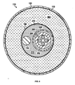
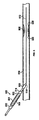
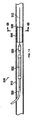
図1及び図2は、本開示の特定の実施形態による例示のDEBカテーテル100を示す図である。図1は、電子的に作動するセンサ116(すなわちイメージング装置)を有するDEBカテーテル100を示し、図2は、ドライブシャフトによって回転されるセンサ117(すなわちイメージング装置)を有するDEBカテーテルを示す。本開示の利益を有する当業者によって理解されるように、センサ116は、固定され、DEBカテーテル100の他の素子に対して相対的に移動することができず、センサ117は、後述されるようにそれがDEBカテーテル100の他の素子に対し中央シャフト114内部で長手方向に移動することができるように、回転可能であり、サイズ設計される。システムの構成要素は、本開示を通じて同じ参照数字によって言及されることができる多くの一般的な素子を有する。特定の例示の実施形態によれば、DEBカテーテル100は、内側スリーブ108と、薬剤溶出コーティング120が位置付けられる外側スリーブとを有するDEBアセンブリ110(すなわちバルーンアセンブリ)を有する。DEBアセンブリ110は、近位接合部106を通じて近位シャフト104に結合される。更に、DEBアセンブリ110は、遠位接合部112を通じて中央シャフト114に結合される。図示される実施形態において、中央シャフト114は、DEBアセンブリ110と検知装置116との間に延在する。ガイドワイヤルーメン103を規定する内側部材102は、カテーテルの先端118から、近位シャフト104、DEBアセンブリ110及び中央シャフト114の内部を通って、少なくともDEBアセンブリ110の近位端部に延びる。
1 and 2 are views showing an
近位シャフト104は、DEBアセンブリ110を加圧流体システムに接続し、近位シャフト104内に延在する電気導体又は光学ファイバのような接続媒体208(図3−図4)が、DEBカテーテル100の近位端部において、検知装置116を処理システム(図示せず)に接続する。特定の実施形態において、検知装置116は、3.14の最大外側直径を有する超音波トランスデューサアレイであり、接続媒体208は、7つの個別の絶縁された電気導体を有する編組外面を有するマイクロケーブルである。他の実施形態において、接続媒体208は、光ファイバを有する。更に別の実施形態において、接続媒体208は、DEBアセンブリ110の全体の長さにわたって延在し、検知装置116と結合する。
The
処理システムは、一般には患者の外部にある。しかしながら、本開示は、このような実施形態に制限されない。本開示の利益を有する当業者によって理解されるように、処理システムは、検知装置116から受信されるデータを使用する。検知装置116がイメージングシステムの一部である場合、データは、画像を生成するために使用されることができる。DEBカテーテルが、患者の動脈を通って移動するに従って、画像が、医療専門家に対しリアルタイムに表示されることができる。これは、医療専門家が、患者血管の全体を通じて存在しうるさまざまな閉塞又は他の異常(すなわち処置領域)を見つけることを可能にする。特定の実施形態において、検知装置116は、圧力又はフローセンサでありえ、処理システムは、検知されたデータに基づいて血流予備量比の値を算出することができる。 The processing system is generally outside the patient. However, the present disclosure is not limited to such embodiments. The processing system uses the data received from the detector 116, as will be appreciated by those skilled in the art who have the benefit of the present disclosure. If the detector 116 is part of an imaging system, the data can be used to generate an image. Images can be displayed in real time to healthcare professionals as the DEB catheter travels through the patient's arteries. This allows healthcare professionals to find various obstructions or other abnormalities (ie, treatment areas) that may be present throughout the patient's blood vessels. In certain embodiments, the detector 116 can be a pressure or flow sensor, and the processing system can calculate the value of the blood flow reserve ratio based on the detected data.
図3及び図4を参照して、近位シャフト104は、プラスチック、ポリマ、金属又は他の可撓性材料で作られることができる。1つの例において、近位シャフト104は、遠位ポリマチューブに結合される金属近位部分を有することができ、遠位ポリマチューブは、カプリングに隣接してポリマチューブに埋め込まれる金属ワイヤを有し、チューブのスチフネスはより固い金属からより可撓性の高いポリマチューブへと遷移する。近位シャフト104は、それが血管に損傷を与えることなく患者の血管内を効果的に通ることができるように、可撓性に設計される。近位シャフト104は、特定の実施形態においてデュアルルーメンシャフトでありうる。デュアルルーメン近位シャフト104は、内側ルーメン及び外側ルーメンを有するアキシャルデュアルルーメンシャフトでありうる。
With reference to FIGS. 3 and 4, the
特定の例示の実施形態において、近位シャフト104は、2乃至4フレンチ(すなわち0.67〜1.33mm)のレンジの直径を有することができる。近位シャフト104の長さは、DEBアセンブリ110及び検知装置116が患者血管の十分に深い領域に到達することを可能にするように十分長い。例えば、近位シャフト104は、約150cmの長さを有することができる。崩壊した状況において、DEBアセンブリ110の最大外側直径は、約0.040インチである。
In certain exemplary embodiments, the
内側部材102は、ガイドワイヤ(図9に図示)を受容するようにサイズ設計されるガイドワイヤルーメン103を規定する。一実施形態において、ガイドワイヤルーメン103は、それが直径0.014インチのガイドワイヤを受容することができるように0.017インチの直径を有する。一般に、ガイドワイヤが最初に患者の血管に挿入される。それから、内側部材102がガイドワイヤを取り囲むように、カテーテルがガイドワイヤ上に配置される。ある例において、内側部材102は、近位シャフト104の先端118から近位端部まで、DEBカテーテル100の全体の長さに延在することができる。このようなカテーテルは、オーバーザワイヤカテーテルと呼ばれる。ある例において、内側部材102は、短い距離に沿って延び、その後、DEBアセンブリ110の近位端部の近くの出口ポートにおいて、DEBカテーテル100から出ることができる。このようなカテーテルは、ラピッドエクスチェンジカテーテルと呼ばれる。
The
内側部材102の長さは、カテーテルがガイドワイヤ上で始まるポイント(一般に先端)から、ガイドワイヤがカテーテルを出るポイントまで延在するに十分長い。こうして、長さは、ラピッドエクスチェンジカテーテルの場合は相対的に短く、オーバーザワイヤカテーテルの場合は相対的に長くなりうる。それにもかかわらず、この例では、中央シャフト114が、DEBアセンブリ110の遠位端と検知装置116との間に接続される。中央シャフト114は、ポリマ、プラスチック又は他の可撓性材料で作られることができる。中央シャフト114は、それが動脈に損傷を与えることなく患者の動脈内を効果的に通ることができるように、可撓性である。内側部材102は、中央シャフト114の内部を通って延びる。更に、詳しく後述されるように、接続媒体は、検知装置116から中央シャフト114を通ってDEBアセンブリ110に向かって延びる。
The length of the
図3は、本開示の1つの例示の実施形態によるDEBカテーテル100の近位接合部106の例示の断面を示す図である。近位接合部106は、DEBアセンブリ110の近位端部を近位シャフト(例えば図1の104)に接続する。特定の例によれば、近位シャフト104は、内側ルーメン204及び外側のルーメン202を有するデュアルルーメンシャフトである。近位接合部106は、更に、内側部材102、内側バルーンスリーブ108、及び接続媒体208が通る空間を有する。近位接合部106は更に、バルーン近位脚部206を有する。1つの見地において、バルーン近位脚部206は、薬剤溶出コーティング120が位置付けられるバルーン外側スリーブを形成する材料の延長である。
FIG. 3 is a diagram showing an exemplary cross section of the
図4は、図2に示される実施形態の断面図を示す。図4の実施形態は、回転駆動ケーブルアセンブリとして形成される代替の接続媒体208'を有する。ケーブルは、内側駆動ケーブル252及び一連の電気導体又は光学ファイバ254を囲む外側シース250を有する。
FIG. 4 shows a cross-sectional view of the embodiment shown in FIG. The embodiment of FIG. 4 has an alternative connection medium 208'formed as a rotary drive cable assembly. The cable has an
近位シャフト104の外側ルーメン202は、近位シャフト104のための外部構造を提供する。内側ルーメン204は、外側ルーメン202より直径が小さく、外側ルーメン202内で軸方向に延びる。外側ルーメン内に、内側部材102、内側バルーンスリーブ108及び接続媒体208のための十分な場所があるように、内側ルーメン204のサイズが設計される。
The
この例示の実施形態において、内側ルーメン204は、DEBアセンブリ110に膨張流体をポンピングするために使用されることができる。こうして、本開示の利益を有する当業者によって理解されるように、近位接合部106の内部の内側ルーメン204の端部は、膨張流体が内側ルーメン204を出てDEBアセンブリ110に入る膨張ポートとして機能する。膨張流体はバルーン内側スリーブ108とバルーン外側スリーブとの間の空間に出て行き、こうして、バルーンを膨張させる。
In this exemplary embodiment, the
バルーン内側スリーブ108は、膨張流体と、DEBカテーテル100の内部の部分を通って延びる任意の構造との間で、特に障壁、接続媒体208及び内側部材102として働く。バルーン内側スリーブ108は、近位シャフト104の外側のルーメン202の内部に結合される。更に、バルーン内側スリーブ108は、内側部材102を有する。図5及び図6に充分に示されるように、任意の接続媒体208又は208がその中にフィットすることを可能にするための十分な空間212がスリーブ108と内側部材102との間にあるように、バルーン内側スリーブ108はサイズ設計される。この空間212は、DEBアセンブリ110の完全性に損傷を与えることなく接続媒体208又は駆動ケーブル208がフロートすることを可能にする。しかしながら、結合材料213(図5−図6)が、DEBアセンブリ110内の内側スリーブ108内の流体密閉領域212を規定するように、近位接続部106及び遠位接続部112内の空間を充填する。
The balloon
1つの例において、内側スリーブ108は、20気圧(「ATM」)より大きい高圧動作に適したマルチレイヤ構造で形成される。ある実施形態において、内側スリーブ108は、例えば、15乃至25気圧のレンジの動作圧力に適するように構成される。一実施形態において、このレンジは、17乃至22気圧でありうる。別の実施形態において、このレンジは、19乃至21気圧でありうる。他のレンジもまた企図される。内側スリーブ108の材料特性及び構造は、高圧の適用下であってもDEBアセンブリ110の長手軸に沿って大きな伸張なしに、それが高圧下で変形することを可能にする。ある実施形態において、内側スリーブ108を形成する材料は、高圧の適用下であっても、軸方向の圧縮及び伸張をほとんど許容しない。
In one example, the
一実施形態において、内側スリーブ108は、マレイン酸変性ポリエチレンの外側層に結合されるポリエチレン(「PE」)の内側層によって形成される。マレイン酸変性ポリエチレンの外側層は、PBAXで形成されることができる近位シャフト104及び中央シャフト114のような、システムの他のコンポーネントに対するサーマル処理ボンディングにより良く適している。当業者には、近位シャフト104、中央シャフト114及び内側シャフト102は、それらが高い動作圧力下で変形しないように形成され、その一方、内側スリーブ108が、バルーンシステムの高い動作圧力下で弾力的に内方に意図的に変形するように設計されることが理解される。内側スリーブ108は、内側スリーブ108を通る接続媒体又は駆動ケーブルの動作を損なわない又は他のやり方でかかる動作と干渉することなしに、接続媒体208又は駆動ケーブル208'の周りに倒れるように形作られ構成される。内側スリーブ108は、高圧力条件が除去されると、その元の形状に弾力的に戻る。その元の形状への内側スリーブ108の戻りは、空間212内の圧縮ガスによって更に助けられることができる。
In one embodiment, the
特定の実施形態において、様々なタイプの接続媒体が、内側部材102と内側スリーブ108との間の空間212に延在することができる。例えば、検知装置116、117が、外部システムによって処理されるべき電気信号を生成する場合、接続媒体208、208'は、電気信号を運ぶための導電性ワイヤを含むことができる。代替として、接続媒体は、光の形でそれらの信号を伝播するための光ファイバケーブルを含むことができる。ワイヤ又はケーブルの数は、検知装置のタイプ、及びデータが検知装置から外部処理システムへ伝送される態様に依存する。導電性ワイヤは、電力を検知装置に供給するために使用されることもできる。
In certain embodiments, various types of connecting media can extend into the
検知装置が回転可能である場合(すなわち検知装置117)、接続媒体208'は、ドライブシャフトルーメンを含むことができる。1つの見地において、ドライブシャフトルーメンは、液体潤滑剤で満たされるプラスチックシース、例えばシース250を有することができる。潤滑剤は、プラスチックシースに沿って延在するドライブシャフトが、プラスチックシースの内部に対し摩擦の最小量を伴ってスピンすることを可能にする。
If the detection device is rotatable (ie, detection device 117), the connection medium 208'can include a drive shaft lumen. In one respect, the drive shaft lumen can have a plastic sheath filled with liquid lubricant, such as
バルーン近位脚部206は、薬剤溶出コーティング120が位置付けられるバルーン外側スリーブの一部である(図1)。図3−図4に示すように、バルーン近位脚部206は、近位シャフト104の外側の周りにしっかりとフィットするように設計される。バルーン近位脚部206は、さまざまなボンディング方法によって近位シャフト104の外側に結合されることができる。これらのボンディング方法は、サーマルボンディング及びレーザボンディングを含むが、これに限定されるものではない。
The balloon
図3は、図1のライン3A−3Aに沿って得られるDEBアセンブリ110の例示の断面を示す図である。或る例によれば、断面は、バルーン外側スリーブ119、バルーン内側スリーブ108、接続媒体208及び内側部材102を含む。薬剤溶出コーティング120は、例えば、プライマメインコート及びトップコートを使用してバルーン外側スリーブ119上に位置付けられる。薬剤溶出コーティング120は、特定の実施形態において、例えばパクリタキセル及び/又はエベロリムスでありうる。薬剤リリースレートは、本開示の利益を有する当業者によって理解されるように、任意の臨床的に適切な薬剤溶出性バルーン上の任意のリリースレートに匹敵することができる。或る実施形態において、利用される薬剤は、身体中で生物分解され、特定の時間期間内に分解し、それによって、ステント術の必要を取り除く。DEBアセンブリ110のバルーンのサイズは、特定の実施形態において、直径は1mm−80mmのレンジであり、長さは5mm−300mmのレンジである。最終的に、本開示の利益を有する当業者によって理解されるように、本開示の実施形態によって利用されることができるさまざまな薬剤溶出性バルーンがある。
FIG. 3 is a diagram showing an exemplary cross section of the
DEBアセンブリ110の直径は、近位接合部において、DEBアセンブリ110内へポンピングされる膨張流体302の量に依存する。非膨張性バルーン材料の場合、バルーン直径は、特定の直径に固定される。一実施形態において、非従順のバルーンは、約15mmの作動長さを有し、0.5mmのインクリメントで2.0乃至4.0mmのレンジで拡張される直径において利用可能である。別の実施形態において、崩壊した状態のバルーンアセンブリの外側直径は、約0.040インチである。
The diameter of the
DEBアセンブリ110の近位端部の近位シャフト104及びDEBアセンブリ110の遠位端部の中央シャフト114は、独立したシャフトである。特定の実施形態によれば、DEBアセンブリ110の内部を通って延びる連続シャフトがない。そうではなく、DEBアセンブリ110の内部は、接続媒体208及び内側部材102(その中をガイドワイヤが延在することができる)のみを有する。これは、DEBアセンブリ110内の付加の柔軟性を提供する。更に、これは、バルーン内側スリーブ108と内側部材102との間の空間212内で、接続媒体208が自由にフロートすることを可能にする。図示される例において、バルーン内側スリーブ108の端部は、個々の近位及び遠位のカテーテル構成要素に対しシールされ、これによりマイクロケーブル208及び内側部材102を囲む流体密閉チャンバ212を形成する。ある例では、空間212は、空気又は他のガスで満たされることができ、他の例では、空間212は液体で満たされることができる。
The
上述したように、膨張流体は、DEBアセンブリ110が、例えば薬剤溶出コーティング120を病変、狭窄又は神経叢のような処置領域に適用するようなさまざまな医療タスクを実施するように適切にアラインされるとき、DEBアセンブリ110を膨張させるために使用される。こうして、バルーン外側スリーブ119及び薬剤溶出コーティング120の直径は、DEBアセンブリ110の膨張状態に基づいて変化する。バルーンが非従順である実施形態において、その直径は、特定のポイントまで拡大するだけである。バルーンの非従順の性質は、患者の動脈内における非常に大きな拡張を防ぐ。バルーン内側スリーブ108は、DEBアセンブリ110が膨張するとき、バルーン内側スリーブ108が接続媒体208上にあまりに大きな圧力を加えないように、完全性によって設計される。
As mentioned above, the expanding fluid is appropriately aligned so that the
図4は、本開示の一実施形態によるバルーンカテーテル100の遠位接合部112の例示の断面を示す図である。特定の例によれば、遠位接合部112は、バルーンの遠位端において、DEBアセンブリ110を中央シャフト114に接続する。遠位接合部112は、内側部材102、内側バルーンスリーブ108及び接続媒体208が延在する空間212を有する。遠位接合部112は更に、バルーン遠位脚部402を有する。図8は、回転駆動シフトアセンブリ208を有する同様の特徴を示す。ここに詳しく記述されない。さまざまなカテーテルのこれら及び他の代替の特徴に関する他の議論については、本発明の譲受人によって所有される米国非仮出願第14/096,982号(「HIGH PRESSURE THERAPEUTIC AND IMAGING CATHETER」、2013年12月4日出願)を参照されたい。その開示内容は、全体が参照によってここに盛り込まれるものとする。
FIG. 4 is a diagram showing an exemplary cross section of the
上述したように、DEBアセンブリ110は、例えば動脈の閉塞又は病変のようなさまざまなタイプの処置領域を処置するために使用されることができる。DEBアセンブリ110が、患者の血管内に適切に位置付けられると、バルーン外側スリーブ119が、圧力を処置領域に適用するために膨張される。バルーン外側スリーブ119は、一般に、膨張流体によって膨張される。従って、膨張流体は、そのような流体が動脈に漏れる場合に患者に害が無いように、一般に食塩水である。膨張流体は、近位シャフト104の内側ルーメンを通じて、15乃至20気圧のレンジまでバルーンにポンピングされることができ、又は圧力レンジは、バルーンの材料特性に依存してより大きくてもよい。DEBアセンブリ110が膨張されるにつれて、薬剤溶出コーティング120は、処置領域と接触するように強いられる。適用されると、特定の実施形態において、薬剤溶出コーティング120は、例えばパクリタキセルのような抗増殖剤でありうるコーティング薬剤の維持されるリリースを提供する。適切に位置付けられる場合、薬剤溶出コーティング120は、コーティングと接触する血管組織への薬剤の高濃度の迅速なリリースとともに、血管壁全体への均質な薬剤移動を提供する。本開示によって提供されるイメージング素子を利用して、薬剤溶出コーティングと血管壁との間の接触が、バルーンカテーテルの除去前に確認されることができる。
As mentioned above, the
更に、イメージング素子は、初期バルーン拡張プロシージャの間、血管内の正確な薬剤配置を判定するために、血管壁に対するバルーンの対抗を評価するために、及び拡張血管サイズを記録するために、利用されることができる。1つの見地において、イメージング素子は、バルーン及び関連する薬剤コーティングの配置のための正確なロケーションを決定し、例えば血管撮影法、蛍光透視及び圧力検知ガイドワイヤのような他のイメージング及び診断モダリティとデリバリシステムからの画像との相互位置合わせをして、血管内の適切なロケーションにおける正確な配置を確実にするために、血管を評価するために、バルーンデリバリの前に利用されることができる。更に他の見地において、あとから以前の血管内処置を利用する場合、デリバリシステムのイメージング素子は、血管又は病変への以前の薬剤分散のような特徴、ステント及び薬剤コーティングを含む以前の処置の範囲内又はそれに隣接した再狭窄、並びに血管壁に対する以前のステントの並置の評価、をイメージングすることによって、以前の処置の効果及び更なる処置のニーズを評価することができる。 In addition, imaging devices have been utilized during the initial balloon dilation procedure to determine accurate drug placement within the vessel, to assess the balloon's opposition to the vessel wall, and to record dilated vessel size. Can be done. In one respect, the imaging element determines the exact location for the placement of the balloon and associated drug coating, and other imaging and diagnostic modalities and deliveries such as angiography, fluorescence fluoroscopy and pressure sensing guide wires. It can be utilized prior to balloon delivery to evaluate the vessel to reciprocally align with the image from the system and ensure accurate placement at the appropriate location within the vessel. In yet other aspects, when later utilizing previous intravascular treatments, the imaging elements of the delivery system are the scope of previous treatments, including features such as previous drug dispersion in blood vessels or lesions, stents and drug coatings. By imaging internal or adjacent restenosis, as well as an assessment of previous stent juxtaposition on the vessel wall, the effectiveness of previous treatments and the need for further treatment can be assessed.
或る例によれば、バルーン外側スリーブ119は、非従順のバルーンである。非従順のバルーンは、特定の直径まで膨張されるように及びその直径を超えては拡張されないように設計される。これは、バルーン外側スリーブ119があまりに多く拡張することを防ぐ。過剰な拡張は患者の血管に損傷を与えることがあるので、これは重要である。バルーン外側スリーブ119は更に、非常に大きい軸方向の圧縮に抵抗するように設計されることができ、これは、非従順のバルーン外側スリーブ119が所望であるより大きく拡張することを可能にしうる。更に、外側スリーブ119は、非常に大きい軸方向の延伸に抵抗するように設計されることができ、これは、バルーン外側スリーブ120が所望の直径まで拡張することを防ぐことができる。それにもかかわらず、図9−図14に関して以下に詳しく記述されるように、薬剤溶出コーティング120は、処置領域に対するデリバリのために外側スリーブ119の周りに位置付けられる。DEBアセンブリ110は、薬剤溶出コーティング120を処置領域に適用するために膨張され、それによって、バルーンが収縮されたあと、薬剤溶出コーティング120が残る。
According to one example, the balloon
上述したように、検知装置116は、患者の血管内部をイメージングするために使用されることができる。様々なタイプの検知装置が使用されることができる。検知装置116の1つの例はOCT装置である。別の形態において、センサは、スペクトロスコピー又は光音響イメージングのために情報を収集することができる。検知装置116は更に、血管壁に向かって軸から外側に向けてではなく、血管の前方をスキャンする前方監視装置でありうる。 As mentioned above, the detector 116 can be used to image the inside of a patient's blood vessels. Various types of detectors can be used. One example of the detection device 116 is an OCT device. In another embodiment, the sensor can collect information for spectroscopic copying or photoacoustic imaging. The detector 116 can further be an anterior monitoring device that scans the anterior surface of the vessel rather than axially outward towards the vessel wall.
検知装置116は更に、IVUS装置でありうる。使用されることができる2つの一般的なタイプのIVUS装置がある。第1のタイプの装置は、フェイズドアレイとも呼ばれるソリッドステート装置である。ソリッドステートIVUS装置は、装置の外周の周りに分布される超音波トランスデューサのアレイを有するトランスデューサ構造体を保持する。トランスデューサは、トランスデューサコントローラの組に接続される。トランスデューサコントローラは、超音波パルスを送信し、エコー信号を受信するために個別のトランスデューサを選択する。送信−受信ペアのシーケンスをステッピングすることによって、ソリッドステートIVUSシステムは、可動部分なしに、機械的にスキャンされるトランスデューサ素子の効果を兼ね備えることができる。回転する機械構成素子がないので、トランスデューサアレイは、血管外傷の最小リスクを有して血液及び血管組織と直接に接触するように配置されることができる。更に、回転素子がないので、インタフェースが簡略化される。ソリッドステートスキャナは、簡単な電気ケーブル及び標準の着脱可能な電気コネクタを有するイメージングシステムに直接にワイヤ接続されることができる。 The detector 116 can further be an IVUS device. There are two common types of IVUS equipment that can be used. The first type of device is a solid state device, also called a phased array. The solid-state IVUS device holds a transducer structure with an array of ultrasonic transducers distributed around the perimeter of the device. Transducers are connected to a set of transducer controllers. The transducer controller selects individual transducers to send ultrasonic pulses and receive echo signals. By stepping the transmit-receive pair sequence, the solid state IVUS system can combine the effects of a mechanically scanned transducer element without moving parts. Since there are no rotating mechanical components, the transducer array can be placed in direct contact with blood and vascular tissue with minimal risk of vascular trauma. Moreover, since there is no rotating element, the interface is simplified. The solid-state scanner can be wire-connected directly to an imaging system that has a simple electrical cable and a standard removable electrical connector.
検知装置としてのトランスデューサアレイの例において、カテーテルシャフトを通って延在する接続媒体は、トランスデューサアレイと外部処理システムとの間でデータを通信する電気ケーブルを含む。接続媒体を含むワイヤ及びケーブルの数は、トランスデューサアレイのタイプに依存することができる。例えば、64ビットアレイは、32ビットアレイより多くのケーブルを使用することができる。更に、さまざまな多重化機能が、カテーテルシャフト通って延びるワイヤの数を低減するために使用されることができる。 In the example of a transducer array as a detector, the connecting medium extending through the catheter shaft includes an electrical cable that communicates data between the transducer array and an external processing system. The number of wires and cables containing the connection medium can depend on the type of transducer array. For example, a 64-bit array can use more cables than a 32-bit array. In addition, various multiplexing functions can be used to reduce the number of wires extending through the catheter shaft.
IVUS装置の第2の一般のタイプは、回転装置(例えば検知装置117)である。典型的な回転IVUS装置は、可撓性ドライブシャフトの先端に位置する単一超音波トランスデューサ素子を含む。トランスデューサは、従来のプラナーPZTタイプトランスデューサでありえ、又は、トランスデューサは、集束トランスデューサでありえ、例えば、集束音響コンピュータトモグラフィ(Focused Acoustic Computed Tomography、「FACT」)を可能にする圧電マイクロマシン超音波トランスデューサ(「PMUT」)タイプの装置である。特定の実施形態において、トランスデューサは、DEBアセンブリ110の遠位に位置付けられ、他方、別の実施形態では、トランスデューサは、DEBアセンブリ110内の内側スリーブ108内に位置付けられる。更に別の実施形態において、DEBアセンブリ110及びトランスデューサが互いに対して移動可能であるように、トランスデューサは内側スリーブ108に沿って移動可能である。それでもやはり、いずれの実施形態においても、ドライブシャフトは、関心ある血管に挿入されるプラスチックシース内部で回転する。トランスデューサ素子は、超音波ビームが装置の軸に対して概して垂直に伝播するように、方向付けられる。流体充填シースは、超音波信号がトランスデューサから組織へ及びその逆に伝播することを可能にするとともに、回転するトランスデューサ及びドライブシャフトから血管組織を保護する。ドライブシャフトが回転するにつれて、トランスデューサは、超音波のショートバーストを放出するために高電圧パルスによって周期的に駆動される。同じトランスデューサが、さまざまな組織構造、バルーン及び薬剤コーティングから反射される戻りのエコーをリスンする。IVUSイメージングシステムは、トランスデューサの単一回転の間に生じるパルス/取得サイクルのシーケンスから、血管断面の2次元表示を生成する。
The second general type of IVUS device is a rotating device (eg, detector 117). A typical rotating IVUS device includes a single ultrasonic transducer element located at the tip of a flexible drive shaft. The transducer can be a conventional planner PZT type transducer, or the transducer can be a focusing transducer, eg, a piezoelectric micromachine ultrasonic transducer ("FACT") that enables Focused Acoustic Computed Tomography ("FACT"). PMUT ") type device. In certain embodiments, the transducer is located distal to the
回転アレイ(例えば検知/イメージング装置116)の例において、カテーテルシャフトを通って延在する接続媒体は、回転アレイを駆動するために使用されるドライブシャフト252(図4及び図6)を囲むプラスチックシース250を含むドライブシャフトルーメンを含む。更に、接続媒体は、トランスデューサアレイと外部処理システムとの間でデータを通信する任意の電気ケーブル254を含む。
In the example of a rotating array (eg, detection / imaging device 116), the connecting medium extending through the catheter shaft is a plastic sheath surrounding the drive shaft 252 (FIGS. 4 and 6) used to drive the rotating array. Includes drive shaft lumens including 250. In addition, the connecting medium includes any
図9−図11は、本開示の特定の例示の方法によるDEBカテーテル500の患者への挿入を示す。DEBカテーテル500は、ここに述べられる任意の差を除いてDEBアセンブリ110及び検知装置116と実質的に同様であるDEBアセンブリ502及びイメージング装置503をそれぞれ有する。DEBカテーテル500の内側スリーブ504は、ここに述べられる任意の差を除いて、内側スリーブ108と実質的に同様である。内側スリーブ108に関して上述したように、ある実施形態において、内側スリーブ504は、20気圧より大きい高圧能力を有し、これは、DEBアセンブリ502を非従順のポスト伸張に適したものにする。例えば、図9−図13は、本開示の一実施形態により、血管内処置領域(例えば病変506)にアクセスし、血管内病変506を評価し、及び、薬剤溶出コーティング508を使用して血管内病変506を処置するための、DEBカテーテル500の使用を示す。
9-11 show the insertion of the
図9は、患者の血管510へと進められるDEBカテーテル500を示す。最初に、ガイドワイヤ512は、血管510に入れられる。1つの見地において、約0.014インチの直径を有するガイドワイヤが利用されることができる。DEBカテーテル500は、患者の血管510の中により深く、ガイドワイヤ502に沿って移動されることができる。血管510へのDEBカテーテル500の挿入の間、DEBアセンブリ502は、膨張されず、拡張されてない状態の小さい縦断面を維持する。DEBカテーテル500の遠位端514は、血管510へのエントリ及び進行を容易にするように設計されることができる。例えば、遠位端514は、テーパ状でありうる。
FIG. 9 shows a
図9に示すように、DEBカテーテル500は、イメージング装置503及びDEBアセンブリ502の遠位接合部516が血管510に入るまで、血管510に押し込まれる。それからDEBカテーテル500は、DEBアセンブリ502の近位接合部518が血管510に入るまで、血管510に更に押し込まれる。その後、DEBカテーテル500は、近位シャフト520が血管510の外側及び患者の外側に延在する状態で、血管510に更に押し込まれる。
As shown in FIG. 9, the
図10は、患者の血管510内の病変506を通って移動するDEBカテーテル500を示す。イメージング装置503は、病変506を検出し評価するために使用されることができる。病変506は、近位端部525及び遠位端530を有し、近位端部525から遠位端部530までの長さL1をもつ。DEBカテーテル500が血管510の中を通るに従って、ヘルスケア専門家は、血管510の健康を評価するためにイメージング装置503によって得られるデータを見ることができる。イメージングデータは、非限定的な例として血管内病変506のような或るタイプの血管内病変又は外傷があるかどうかを医師に知らせることができる。イメージングデータは更に、例えば非限定的な例として血管510の経路及び/又はねじれ、血管510内の壁の規則性又は不規則性、及び血管510囲内の血流についてのさまざまな特性のような他の脈管特性を伝達することができる。
FIG. 10 shows a
病変506を視覚化する際、DEBカテーテル500は、DEBアセンブリ502が病変506とアラインされるまで、血管510内を更に進められる。DEBカテーテル500の遠位端514が病変506を通って進むに従って、イメージング装置503は、血管をイメージングすることを続けることができ、それによって、DEBアセンブリ502のロケーションの正確な評価をヘルスケア専門家に提供する。特に、イメージング装置503は、DEBアセンブリ502から固定の距離D1のところに位置付けられ、これは、ヘルスケア専門家が、所与の時間にイメージング装置503がイメージングしているいかなる血管内位置に対してもDEBアセンブリ502を位置付けるよう、DEBカテーテル500を固定の距離前進させる及び/又は引き戻すことを可能にする。
When visualizing
イメージング装置503は更に、病変506に隣り合うDEBアセンブリ502の配置を容易にするために使用されることができる。図示される例において、病変506は、処置として縮小及びコーティングを必要とする血管内閉塞である。図10及び図11に示すように、イメージング装置503が病変506を通って進行するに従って、イメージング装置503によって伝達される画像データは、例えば非限定的な例として、病変506の長さLI、病変506の管腔輪郭(例えば病変506の近位、隣接、遠位のところの血管510腔内直径)、及び病変506を通る血流の特性のような血管510内のさまざまな解剖学的な特性を、ヘルスケア専門家に知らせることができる。このイメージングデータを使用して、ヘルスケア専門家は、拡張されていないDEBアセンブリ502及び上にある薬剤溶出コーティング508を病変506の範囲内に正確に位置付けるために、DEBカテーテル500を適当な距離前進させることができる。特定の実施形態において、薬剤溶出コーティング508は、近位端部535から遠位端部540までの長さL2をもつ。ヘルスケア専門家は、薬剤溶出コーティング508の長さL2が、長さL1をもつ病変506を処置するのに適当かどうかを評価することができる。加えて、ヘルスケア専門家は、薬剤溶出コーティング508の直径が病変506を処置するのに適当であることを検証することができる。薬剤溶出コーティング508が、病変506を適切に処置するにはあまりに短く、あまりに長く、あまりに大きく、又はあまりに細長い場合、DEBカテーテル500は、取り除かれ、正しいサイズの薬剤溶出コーティング508を保持するカテーテルと置き換えられることができ、それにより、病変506を完全にカバーするためのコーティングの不良を回避する。
図11は、患者の血管510内の病変506の範囲内における、DEBアセンブリ502及び薬剤溶出コーティング508の拡張を示す。ヘルスケア専門家が、病変506の範囲内に適切にDEBアセンブリ502及び薬剤溶出コーティング508を(拡張されてない状態で)前進させたのち、ヘルスケア専門家は、病変506によってもたらされる閉塞を緩和し及び薬剤溶出コーティング508を病変506に適用するために、DEBアセンブリ502を膨張させることができ、こうして、病変506のロケーションにおける血管510の新たな開通性を維持する。上述したように、これは、DEBカテーテル500の近位シャフト520の内側ルーメンを通じて膨張流体をポンピングすることによって行われることができる。DEBアセンブリ502が、一般に15−25気圧のレンジの高い圧力の下で膨張されるに従って、薬剤溶出コーティング508は、拡張された状態を呈し、血管510の内側壁に対し病変506を平坦化し、それと同時に、病変506に付着する。
FIG. 11 shows the expansion of
図12は、病変506上への薬剤溶出コーティング508の初期適用の後の、病変506からのDEBアセンブリ502の取り出しを示す。ヘルスケア専門家は、DEBアセンブリ502を収縮させ、イメージング装置503が薬剤溶出コーティング508より近位に位置されるまでDEBカテーテル500を引き戻すことができる。ヘルスケア専門家は、薬剤溶出コーティング508の拡張及び適用を評価するために、病変506及び薬剤溶出コーティング508に隣り合って現在位置付けられているイメージング装置503によって受け取られたイメージングデータを使用することができる。特に、イメージングデータは、ヘルスケア専門家が、血管510内の薬剤溶出コーティング508及び病変506の並置を評価することを可能にする。時には、図12に示すように、DEBアセンブリ502/薬剤溶出コーティング508の初期拡張が、薬剤溶出コーティング508及び病変506の完全な並置を生じさせるのに不十分なことがあり、こうして、図15に示すように空隙550を生じさせることがある。例えば、図示される実施形態において、薬剤溶出コーティング508は、血管510の壁545に対し病変506を完全にはコーティング又は圧縮していない。その代わりに、病変506は、部分的にもとのままであり、少なくとも部分的に血管510の中のフローを塞ぎ、又はそれが完全にはコーティングされていないのでその成長を続けることができる。イメージング装置503は、ヘルスケア専門家にイメージングデータを通じてこの情報を伝達することができる。
FIG. 12 shows the removal of
図13は、病変506の範囲内へのDEBアセンブリ502の再挿入及び再膨張を示す。薬剤溶出コーティング508及び病変506の並置を評価したのち、ヘルスケア専門家が、DEBアセンブリ502の拡張を増大し、空隙550を除去し、及び/又は病変506のプロファイルを一層低減させることを望む場合、ヘルスケア専門家は、DEBカテーテル500を再び前進させ、薬剤溶出コーティング508及び病変506の範囲内にDEBアセンブリ502を再び位置付けることができる。図13に示すように、DEBアセンブリ502は、病変506に対し薬剤溶出コーティング508を一層拡張させるようにより高い圧力で再び膨張されることができる、それにより、並置を改善し、空隙550の存在を除去し及び/又は低減することができる。
FIG. 13 shows the reinsertion and reswelling of
例えば、初期膨張圧力が17気圧である場合、次の膨張圧力は20気圧でありうる。別の例において、初期膨張圧力が20気圧である場合、次の膨張圧力は25気圧でありうる。初期圧力及び次の圧力の間の他の変化が更に企図される。ある実施形態において、次の圧力は、予め決められたパーセンテージで初期圧力より大きくされることができる。例えば、一例を挙げると、次の膨張圧力は、初期膨張圧力より少なくとも25%大きくされることができる。他の予め決められたパーセンテージの増加が更に企図される。ある実施形態において、ヘルスケア提供者は、処置装置の一層の拡張の所望の程度によって、初期圧力と次の圧力との間の変化量又は増分を選択することができる。 For example, if the initial expansion pressure is 17 atm, the next expansion pressure can be 20 atm. In another example, if the initial expansion pressure is 20 atm, the next expansion pressure can be 25 atm. Other changes between the initial pressure and the next pressure are further contemplated. In certain embodiments, the next pressure can be greater than the initial pressure by a predetermined percentage. For example, the next expansion pressure can be increased by at least 25% above the initial expansion pressure, for example. Other pre-determined percentage increases are further contemplated. In certain embodiments, the healthcare provider can choose the amount or increment between the initial pressure and the next pressure, depending on the desired degree of further expansion of the treatment device.
図14は、病変506に対する薬剤溶出コーティング508の二次適用の後の、病変506からのDEBアセンブリ502の取り出しを示す。ヘルスケア専門家は、DEBアセンブリ502を再び収縮させ、イメージング装置503が薬剤溶出コーティング508より近位に位置付けられるまで、DEBカテーテル500を引き戻すことができる。ヘルスケア専門家は、薬剤溶出コーティング508と病変506との間の並置を評価するために、イメージング装置503によって受け取られたイメージングデータを使用することができる。イメージングデータが図16に示すように(例えば適当な位置付けに加えて)完全な並置を示す場合(空隙550が除去されている)、ヘルスケア専門家は、血管510(及び患者の身体)からDEBカテーテル500を引き抜くことができる。
FIG. 14 shows the removal of
特定の他の実施形態において、図9−図14に関して上述したように、ヘルスケア専門家は、正確な位置付け、再度の位置付け及び薬剤溶出コーティング508のリアルタイムの使用を検証するためのイメージングと組み合わされて、次第に増大される圧力でDEBアセンブリ502を膨張させることができる。
In certain other embodiments, as described above with respect to FIGS. 9-14, healthcare professionals are combined with imaging to verify accurate positioning, repositioning and real-time use of
図示しないが、或る代替の方法において、DEBカテーテル500は、図2に示され上述されたように、回転イメージング装置(例えばセンサ117)を利用することができる。図2及び図9−図14に関して、このような実施形態において、イメージング装置117が病変506をイメージングしたのち、イメージング装置117は、病変506に隣接する又は病変506の範囲内の静止位置に保持されることができる。DEBアセンブリ502及びイメージング装置117は、このような実施形態において互いに対し移動可能であるので、DEBアセンブリ502がイメージング装置117上に(及びイメージング装置117が病変の範囲内に位置付けられるので、病変506の範囲内に)位置付けられるように、DEBアセンブリ502は、イメージング装置117に対し移動されることができる。その後、DEBアセンブリ502は、ここに記述されるように拡張されることができる。DEBアセンブリ502が膨張される間、イメージング装置117は、DEBアセンブリ502によって移動され、それにより、薬剤溶出コーティング508及び病変506の並置をイメージングすることができる。並置が不完全であることが見つけられる場合、DEBアセンブリ502は、存在する空隙550を最小限にする及び/又は除去するための努力において、より高い圧力で一層膨張されることができる。イメージング及び一層の膨張プロセスが、必要に応じて繰り返されることができる。
Although not shown, in some alternative method, the
本開示の更に別の実施形態において、距離マーカが、患者身体の外側に突出するDEBカテーテルのシャフトに沿って位置付けられることができる。ここに記述される処置プロシージャの間、距離マーカの位置は、固定のコンポーネント(例えば、アクセスカテーテル、ルアーロック、その他)に対してビューされることができ、それにより、イメージング装置の以前の位置にDEBアセンブリを持ってくるように上述した固定の距離DEBカテーテルを移動させることができる。他の実施形態において、距離マーカは、DEBアセンブリ自体に位置付けられることもでき、イメージング装置は、DEBカテーテルの必要な移動が決定されるように、距離マーカをビューするために使用される。更に別の実施形態において、蛍光透視は、カテーテルの外側に沿った放射線不透過マーカバンドをイメージングするために使用されることができる。 In yet another embodiment of the present disclosure, the distance marker can be positioned along the shaft of the DEB catheter that projects outward of the patient's body. During the procedure described herein, the position of the distance marker can be viewed with respect to a fixed component (eg, access catheter, luer lock, etc.), thereby in the previous position of the imaging device. The fixed distance DEB catheter described above can be moved to bring the DEB assembly. In other embodiments, the distance marker can also be positioned in the DEB assembly itself, and an imaging device is used to view the distance marker so that the required movement of the DEB catheter is determined. In yet another embodiment, fluoroscopy can be used to image a radiopaque marker band along the outside of the catheter.
ここに記述される例示の実施形態は、例えば病変及び冠状動脈狭窄の処置を含むさまざまなアプリケーションにおいて利用されることができる。更に、例示のDEBカテーテルは、腎除神経プロシージャのために使用されることができる。このようなアプリケーションにおいて、遅効性薬物が、薬剤溶出コーティングとして利用され、薬剤溶出コーティングは、30−90日持続し、神経を脱感作する。これは、神経に永久に損傷を与えることなく技法が高血圧を緩和するかどうか決定するためのトライアル手順を、患者に与える。代替のアプリケーションにおいて、遅効性薬剤溶出コーティングは、神経に永久的に損傷を与えて、それにより除神経を達成することもできる。本発明のこれら及び他のアプリケーションは、本開示の利益を有する当業者にとって明らかである。 The exemplary embodiments described herein can be utilized in a variety of applications, including, for example, the treatment of lesions and coronary artery stenosis. In addition, the exemplary DEB catheters can be used for renal denervation procedures. In such applications, slow-acting drugs are utilized as drug-eluting coatings, which last for 30-90 days and desensitize nerves. This gives the patient a trial procedure to determine if the technique relieves hypertension without permanently damaging the nerves. In alternative applications, slow-acting drug-eluting coatings can also permanently damage nerves, thereby achieving denervation. These and other applications of the present invention will be apparent to those skilled in the art who have the benefit of the present disclosure.
例示の実施形態が図示され記述されたが、広範囲の変形、変更及び置き換えが、上述の開示において企図され、ある例において、本開示のある特徴は、他の特徴の対応する使用なしに用いられることができる。このような変更は、本開示の要旨を逸脱することなく上述したものの中で行われることができる。従って、添付の特許請求の範囲が広く及び本開示の範囲と合致するように解釈されることが適切である。 Although exemplary embodiments have been illustrated and described, a wide range of modifications, modifications and replacements are contemplated in the disclosures described above, and in one example some features of the present disclosure are used without the corresponding use of other features. be able to. Such changes may be made within those described above without departing from the gist of the present disclosure. Therefore, it is appropriate that the appended claims be broadly construed to be consistent with the scope of the present disclosure.
Claims (6)
ガイドワイヤルーメンを規定する内側部材と、
前記内側部材上に位置付けられるバルーンアセンブリと、
前記バルーンアセンブリ上に位置付けられる薬剤溶出コーティングと、
前記内側部材上に位置付けられるイメージング装置と、
を有し、
前記イメージング装置及び前記バルーンアセンブリは、互いに対し移動可能である、
カテーテル。 An integrated treatment and imaging catheter
The inner member that defines the guide wire lumen and
With the balloon assembly positioned on the inner member,
With the drug elution coating located on the balloon assembly,
An imaging device positioned on the inner member and
Have a,
The imaging device and the balloon assembly are movable relative to each other.
catheter.
Applications Claiming Priority (3)
| Application Number | Priority Date | Filing Date | Title |
|---|---|---|---|
| US201462011276P | 2014-06-12 | 2014-06-12 | |
| US62/011,276 | 2014-06-12 | ||
| PCT/US2015/035609 WO2015192041A1 (en) | 2014-06-12 | 2015-06-12 | Image guided therapeutic catheter with drug eluting balloon |
Publications (3)
| Publication Number | Publication Date |
|---|---|
| JP2017524397A JP2017524397A (en) | 2017-08-31 |
| JP2017524397A5 JP2017524397A5 (en) | 2018-07-05 |
| JP6814044B2 true JP6814044B2 (en) | 2021-01-13 |
Family
ID=54834424
Family Applications (1)
| Application Number | Title | Priority Date | Filing Date |
|---|---|---|---|
| JP2016570826A Active JP6814044B2 (en) | 2014-06-12 | 2015-06-12 | Image-guided therapeutic catheter with drug-eluting balloon |
Country Status (5)
| Country | Link |
|---|---|
| US (1) | US20150359433A1 (en) |
| EP (1) | EP3154620B1 (en) |
| JP (1) | JP6814044B2 (en) |
| CN (1) | CN106456945B (en) |
| WO (1) | WO2015192041A1 (en) |
Families Citing this family (3)
| Publication number | Priority date | Publication date | Assignee | Title |
|---|---|---|---|---|
| CA2988178A1 (en) * | 2015-06-15 | 2016-12-22 | Sunnybrook Research Institute | Intravascular imaging catheters and methods of use thereof |
| US10813680B2 (en) * | 2017-03-27 | 2020-10-27 | Medtronic Cryocath Lp | Cryoballoon contact assessment using capacitive or resistive sensors |
| WO2023187510A1 (en) * | 2022-03-31 | 2023-10-05 | Medtronic, Inc. | Vessel modification using a therapeutic agent |
Family Cites Families (26)
| Publication number | Priority date | Publication date | Assignee | Title |
|---|---|---|---|---|
| US5090959A (en) * | 1987-04-30 | 1992-02-25 | Advanced Cardiovascular Systems, Inc. | Imaging balloon dilatation catheter |
| US5372138A (en) * | 1988-03-21 | 1994-12-13 | Boston Scientific Corporation | Acousting imaging catheters and the like |
| DK0544820T3 (en) * | 1990-08-21 | 2000-08-07 | Boston Scient Ltd | Acoustic imaging catheter and the like |
| US5102402A (en) * | 1991-01-04 | 1992-04-07 | Medtronic, Inc. | Releasable coatings on balloon catheters |
| US5167233A (en) * | 1991-01-07 | 1992-12-01 | Endosonics Corporation | Dilating and imaging apparatus |
| US5183048A (en) * | 1991-06-24 | 1993-02-02 | Endosonics Corporation | Method and apparatus for removing artifacts from an ultrasonically generated image of a small cavity |
| AU1374095A (en) * | 1993-12-17 | 1995-07-03 | G. David Jang | Sliding receptacle catheter systems |
| GB2365127A (en) * | 2000-07-20 | 2002-02-13 | Jomed Imaging Ltd | Catheter |
| AU2003256856A1 (en) * | 2002-08-05 | 2004-02-23 | Miravant Medical Technologies, Inc. | Catheter for diagnosis and treatment of diseased vessels |
| DE102004001498B4 (en) * | 2004-01-09 | 2008-01-10 | Siemens Ag | Catheter for insertion into a vessel |
| US8396548B2 (en) * | 2008-11-14 | 2013-03-12 | Vessix Vascular, Inc. | Selective drug delivery in a lumen |
| US20070060995A1 (en) * | 2005-08-19 | 2007-03-15 | Oliver Meissner | Workflow for cardiovascular intervention |
| US20070073364A1 (en) * | 2005-09-29 | 2007-03-29 | Siemens Aktiengesellschaft | Combined OCT catheter device and method for combined optical coherence tomography (OCT) diagnosis and photodynamic therapy (PDT) |
| WO2009089372A2 (en) * | 2008-01-08 | 2009-07-16 | Cornova, Inc. | Systems and methods for analysis and treatment of a body lumen |
| US20080175887A1 (en) * | 2006-11-20 | 2008-07-24 | Lixiao Wang | Treatment of Asthma and Chronic Obstructive Pulmonary Disease With Anti-proliferate and Anti-inflammatory Drugs |
| JP5237567B2 (en) * | 2007-02-21 | 2013-07-17 | 株式会社グツドマン | Balloon catheter |
| EP2865404B1 (en) * | 2007-06-01 | 2019-09-11 | Covidien LP | Extension tubes for balloon catheters |
| US8100855B2 (en) * | 2007-09-17 | 2012-01-24 | Abbott Cardiovascular Systems, Inc. | Methods and devices for eluting agents to a vessel |
| US8076529B2 (en) * | 2008-09-26 | 2011-12-13 | Abbott Cardiovascular Systems, Inc. | Expandable member formed of a fibrous matrix for intraluminal drug delivery |
| US20120330148A1 (en) * | 2010-12-31 | 2012-12-27 | Volcano Corporation | Multiple Sclerosis Therapeutic Methods Using Therapeutic Inflatable Devices and Systems |
| US20120310210A1 (en) * | 2011-03-04 | 2012-12-06 | Campbell Carey V | Eluting medical devices |
| WO2013059509A1 (en) * | 2011-10-18 | 2013-04-25 | Micell Technologies, Inc. | Drug delivery medical device |
| US9993628B2 (en) * | 2012-08-22 | 2018-06-12 | Volcano Corporation | Balloon catheter junction |
| EP2887881A4 (en) * | 2012-08-24 | 2016-09-28 | Volcano Corp | System and method for focusing ultrasound image data |
| US9603547B2 (en) * | 2012-12-07 | 2017-03-28 | Volcano Corporation | High pressure therapeutic and imaging catheter |
| US20140276028A1 (en) * | 2013-03-15 | 2014-09-18 | Volcano Corporation | Integrated Therapeutic Imaging Catheter and Methods |
-
2015
- 2015-06-12 JP JP2016570826A patent/JP6814044B2/en active Active
- 2015-06-12 EP EP15806028.5A patent/EP3154620B1/en active Active
- 2015-06-12 CN CN201580031200.6A patent/CN106456945B/en active Active
- 2015-06-12 WO PCT/US2015/035609 patent/WO2015192041A1/en active Application Filing
- 2015-06-12 US US14/738,372 patent/US20150359433A1/en active Pending
Also Published As
| Publication number | Publication date |
|---|---|
| JP2017524397A (en) | 2017-08-31 |
| EP3154620A4 (en) | 2017-05-31 |
| CN106456945A (en) | 2017-02-22 |
| EP3154620B1 (en) | 2020-09-09 |
| US20150359433A1 (en) | 2015-12-17 |
| CN106456945B (en) | 2020-06-16 |
| EP3154620A1 (en) | 2017-04-19 |
| WO2015192041A1 (en) | 2015-12-17 |
Similar Documents
| Publication | Publication Date | Title |
|---|---|---|
| US20190175148A1 (en) | Distance, diameter and area determining device | |
| JP4621771B2 (en) | Imaging system and imaging guidewire | |
| JP5107931B2 (en) | Echogenic needle catheter configured to generate improved ultrasound images | |
| US10709312B2 (en) | Transitional region having cuts and a skive for an imaging catheter | |
| JP6814044B2 (en) | Image-guided therapeutic catheter with drug-eluting balloon | |
| US20140276028A1 (en) | Integrated Therapeutic Imaging Catheter and Methods | |
| EP3229700B1 (en) | Distance, diameter and area measuring device | |
| US20220409858A1 (en) | Electromagnetic-radiation-cured radiopaque marker and associated devices, systems, and methods | |
| JP6382833B2 (en) | High pressure therapeutic and imaging catheters | |
| US11707258B2 (en) | Device and method for intravascular imaging and sensing | |
| EP3672491B1 (en) | Adjustable flexibility/stiffness intraluminal device | |
| US11819360B2 (en) | Intraluminal rotational ultrasound for diagnostic imaging and therapy |
Legal Events
| Date | Code | Title | Description |
|---|---|---|---|
| RD04 | Notification of resignation of power of attorney |
Free format text: JAPANESE INTERMEDIATE CODE: A7424 Effective date: 20170214 |
|
| A521 | Request for written amendment filed |
Free format text: JAPANESE INTERMEDIATE CODE: A523 Effective date: 20180524 |
|
| A621 | Written request for application examination |
Free format text: JAPANESE INTERMEDIATE CODE: A621 Effective date: 20180524 |
|
| A977 | Report on retrieval |
Free format text: JAPANESE INTERMEDIATE CODE: A971007 Effective date: 20190226 |
|
| A131 | Notification of reasons for refusal |
Free format text: JAPANESE INTERMEDIATE CODE: A131 Effective date: 20190319 |
|
| A601 | Written request for extension of time |
Free format text: JAPANESE INTERMEDIATE CODE: A601 Effective date: 20190612 |
|
| A521 | Request for written amendment filed |
Free format text: JAPANESE INTERMEDIATE CODE: A523 Effective date: 20190826 |
|
| A131 | Notification of reasons for refusal |
Free format text: JAPANESE INTERMEDIATE CODE: A131 Effective date: 20200107 |
|
| A601 | Written request for extension of time |
Free format text: JAPANESE INTERMEDIATE CODE: A601 Effective date: 20200407 |
|
| TRDD | Decision of grant or rejection written | ||
| A01 | Written decision to grant a patent or to grant a registration (utility model) |
Free format text: JAPANESE INTERMEDIATE CODE: A01 Effective date: 20201124 |
|
| A61 | First payment of annual fees (during grant procedure) |
Free format text: JAPANESE INTERMEDIATE CODE: A61 Effective date: 20201218 |
|
| R150 | Certificate of patent or registration of utility model |
Ref document number: 6814044 Country of ref document: JP Free format text: JAPANESE INTERMEDIATE CODE: R150 |
|
| R250 | Receipt of annual fees |
Free format text: JAPANESE INTERMEDIATE CODE: R250 |