JP6812422B2 - Catheter circuit - Google Patents
Catheter circuit Download PDFInfo
- Publication number
- JP6812422B2 JP6812422B2 JP2018514943A JP2018514943A JP6812422B2 JP 6812422 B2 JP6812422 B2 JP 6812422B2 JP 2018514943 A JP2018514943 A JP 2018514943A JP 2018514943 A JP2018514943 A JP 2018514943A JP 6812422 B2 JP6812422 B2 JP 6812422B2
- Authority
- JP
- Japan
- Prior art keywords
- hypotube
- catheter
- wires
- proximal end
- catheter according
- Prior art date
- Legal status (The legal status is an assumption and is not a legal conclusion. Google has not performed a legal analysis and makes no representation as to the accuracy of the status listed.)
- Active
Links
- 238000003384 imaging method Methods 0.000 claims description 5
- QVGXLLKOCUKJST-UHFFFAOYSA-N atomic oxygen Chemical compound [O] QVGXLLKOCUKJST-UHFFFAOYSA-N 0.000 claims description 4
- 229910052760 oxygen Inorganic materials 0.000 claims description 4
- 239000001301 oxygen Substances 0.000 claims description 4
- 238000003698 laser cutting Methods 0.000 claims description 3
- 239000004642 Polyimide Substances 0.000 claims description 2
- 230000037361 pathway Effects 0.000 claims description 2
- 229920001721 polyimide Polymers 0.000 claims description 2
- 230000000149 penetrating effect Effects 0.000 claims 2
- 230000008901 benefit Effects 0.000 description 10
- 230000003073 embolic effect Effects 0.000 description 9
- 239000007943 implant Substances 0.000 description 7
- 239000000853 adhesive Substances 0.000 description 5
- 230000001070 adhesive effect Effects 0.000 description 5
- 230000006870 function Effects 0.000 description 5
- 239000000463 material Substances 0.000 description 5
- 239000011248 coating agent Substances 0.000 description 4
- 238000000576 coating method Methods 0.000 description 4
- 229920000052 poly(p-xylylene) Polymers 0.000 description 4
- 230000002787 reinforcement Effects 0.000 description 4
- 239000000470 constituent Substances 0.000 description 3
- 238000003825 pressing Methods 0.000 description 3
- 239000003990 capacitor Substances 0.000 description 2
- 230000003750 conditioning effect Effects 0.000 description 2
- 239000004020 conductor Substances 0.000 description 2
- PCHJSUWPFVWCPO-UHFFFAOYSA-N gold Chemical compound [Au] PCHJSUWPFVWCPO-UHFFFAOYSA-N 0.000 description 2
- 239000010931 gold Substances 0.000 description 2
- 229910052737 gold Inorganic materials 0.000 description 2
- 239000012212 insulator Substances 0.000 description 2
- 230000007246 mechanism Effects 0.000 description 2
- 230000035790 physiological processes and functions Effects 0.000 description 2
- BASFCYQUMIYNBI-UHFFFAOYSA-N platinum Chemical compound [Pt] BASFCYQUMIYNBI-UHFFFAOYSA-N 0.000 description 2
- 208000005189 Embolism Diseases 0.000 description 1
- 239000004952 Polyamide Substances 0.000 description 1
- 230000009471 action Effects 0.000 description 1
- 210000004204 blood vessel Anatomy 0.000 description 1
- 238000001514 detection method Methods 0.000 description 1
- 230000006866 deterioration Effects 0.000 description 1
- 238000007599 discharging Methods 0.000 description 1
- 230000000694 effects Effects 0.000 description 1
- 230000001747 exhibiting effect Effects 0.000 description 1
- 238000001914 filtration Methods 0.000 description 1
- 230000000977 initiatory effect Effects 0.000 description 1
- 239000007788 liquid Substances 0.000 description 1
- 239000007769 metal material Substances 0.000 description 1
- 238000000034 method Methods 0.000 description 1
- 238000012986 modification Methods 0.000 description 1
- 230000004048 modification Effects 0.000 description 1
- HLXZNVUGXRDIFK-UHFFFAOYSA-N nickel titanium Chemical compound [Ti].[Ti].[Ti].[Ti].[Ti].[Ti].[Ti].[Ti].[Ti].[Ti].[Ti].[Ni].[Ni].[Ni].[Ni].[Ni].[Ni].[Ni].[Ni].[Ni].[Ni].[Ni].[Ni].[Ni].[Ni] HLXZNVUGXRDIFK-UHFFFAOYSA-N 0.000 description 1
- 229910001000 nickel titanium Inorganic materials 0.000 description 1
- 239000000615 nonconductor Substances 0.000 description 1
- 229910052697 platinum Inorganic materials 0.000 description 1
- 229920002647 polyamide Polymers 0.000 description 1
- 230000003014 reinforcing effect Effects 0.000 description 1
- 229910001220 stainless steel Inorganic materials 0.000 description 1
- 239000010935 stainless steel Substances 0.000 description 1
- WFKWXMTUELFFGS-UHFFFAOYSA-N tungsten Chemical compound [W] WFKWXMTUELFFGS-UHFFFAOYSA-N 0.000 description 1
- 229910052721 tungsten Inorganic materials 0.000 description 1
- 239000010937 tungsten Substances 0.000 description 1
- 230000002792 vascular Effects 0.000 description 1
- 210000005166 vasculature Anatomy 0.000 description 1
Images


Classifications
-
- A—HUMAN NECESSITIES
- A61—MEDICAL OR VETERINARY SCIENCE; HYGIENE
- A61M—DEVICES FOR INTRODUCING MEDIA INTO, OR ONTO, THE BODY; DEVICES FOR TRANSDUCING BODY MEDIA OR FOR TAKING MEDIA FROM THE BODY; DEVICES FOR PRODUCING OR ENDING SLEEP OR STUPOR
- A61M25/00—Catheters; Hollow probes
- A61M25/0021—Catheters; Hollow probes characterised by the form of the tubing
-
- A—HUMAN NECESSITIES
- A61—MEDICAL OR VETERINARY SCIENCE; HYGIENE
- A61B—DIAGNOSIS; SURGERY; IDENTIFICATION
- A61B5/00—Measuring for diagnostic purposes; Identification of persons
- A61B5/68—Arrangements of detecting, measuring or recording means, e.g. sensors, in relation to patient
- A61B5/6846—Arrangements of detecting, measuring or recording means, e.g. sensors, in relation to patient specially adapted to be brought in contact with an internal body part, i.e. invasive
- A61B5/6847—Arrangements of detecting, measuring or recording means, e.g. sensors, in relation to patient specially adapted to be brought in contact with an internal body part, i.e. invasive mounted on an invasive device
- A61B5/6852—Catheters
-
- A—HUMAN NECESSITIES
- A61—MEDICAL OR VETERINARY SCIENCE; HYGIENE
- A61B—DIAGNOSIS; SURGERY; IDENTIFICATION
- A61B17/00—Surgical instruments, devices or methods, e.g. tourniquets
- A61B17/12—Surgical instruments, devices or methods, e.g. tourniquets for ligaturing or otherwise compressing tubular parts of the body, e.g. blood vessels, umbilical cord
- A61B17/12022—Occluding by internal devices, e.g. balloons or releasable wires
- A61B17/12131—Occluding by internal devices, e.g. balloons or releasable wires characterised by the type of occluding device
- A61B17/1214—Coils or wires
-
- A—HUMAN NECESSITIES
- A61—MEDICAL OR VETERINARY SCIENCE; HYGIENE
- A61M—DEVICES FOR INTRODUCING MEDIA INTO, OR ONTO, THE BODY; DEVICES FOR TRANSDUCING BODY MEDIA OR FOR TAKING MEDIA FROM THE BODY; DEVICES FOR PRODUCING OR ENDING SLEEP OR STUPOR
- A61M25/00—Catheters; Hollow probes
- A61M25/0021—Catheters; Hollow probes characterised by the form of the tubing
- A61M25/0023—Catheters; Hollow probes characterised by the form of the tubing by the form of the lumen, e.g. cross-section, variable diameter
-
- A—HUMAN NECESSITIES
- A61—MEDICAL OR VETERINARY SCIENCE; HYGIENE
- A61M—DEVICES FOR INTRODUCING MEDIA INTO, OR ONTO, THE BODY; DEVICES FOR TRANSDUCING BODY MEDIA OR FOR TAKING MEDIA FROM THE BODY; DEVICES FOR PRODUCING OR ENDING SLEEP OR STUPOR
- A61M25/00—Catheters; Hollow probes
- A61M25/0043—Catheters; Hollow probes characterised by structural features
-
- A—HUMAN NECESSITIES
- A61—MEDICAL OR VETERINARY SCIENCE; HYGIENE
- A61B—DIAGNOSIS; SURGERY; IDENTIFICATION
- A61B17/00—Surgical instruments, devices or methods, e.g. tourniquets
- A61B2017/00017—Electrical control of surgical instruments
- A61B2017/00022—Sensing or detecting at the treatment site
-
- A—HUMAN NECESSITIES
- A61—MEDICAL OR VETERINARY SCIENCE; HYGIENE
- A61B—DIAGNOSIS; SURGERY; IDENTIFICATION
- A61B17/00—Surgical instruments, devices or methods, e.g. tourniquets
- A61B17/12—Surgical instruments, devices or methods, e.g. tourniquets for ligaturing or otherwise compressing tubular parts of the body, e.g. blood vessels, umbilical cord
- A61B17/12022—Occluding by internal devices, e.g. balloons or releasable wires
- A61B2017/1205—Introduction devices
- A61B2017/12054—Details concerning the detachment of the occluding device from the introduction device
- A61B2017/12068—Details concerning the detachment of the occluding device from the introduction device detachable by heat
-
- A—HUMAN NECESSITIES
- A61—MEDICAL OR VETERINARY SCIENCE; HYGIENE
- A61B—DIAGNOSIS; SURGERY; IDENTIFICATION
- A61B2560/00—Constructional details of operational features of apparatus; Accessories for medical measuring apparatus
- A61B2560/06—Accessories for medical measuring apparatus
- A61B2560/063—Devices specially adapted for delivering implantable medical measuring apparatus
-
- A—HUMAN NECESSITIES
- A61—MEDICAL OR VETERINARY SCIENCE; HYGIENE
- A61B—DIAGNOSIS; SURGERY; IDENTIFICATION
- A61B2562/00—Details of sensors; Constructional details of sensor housings or probes; Accessories for sensors
- A61B2562/02—Details of sensors specially adapted for in-vivo measurements
- A61B2562/0247—Pressure sensors
-
- A—HUMAN NECESSITIES
- A61—MEDICAL OR VETERINARY SCIENCE; HYGIENE
- A61B—DIAGNOSIS; SURGERY; IDENTIFICATION
- A61B2562/00—Details of sensors; Constructional details of sensor housings or probes; Accessories for sensors
- A61B2562/22—Arrangements of medical sensors with cables or leads; Connectors or couplings specifically adapted for medical sensors
- A61B2562/221—Arrangements of sensors with cables or leads, e.g. cable harnesses
- A61B2562/222—Electrical cables or leads therefor, e.g. coaxial cables or ribbon cables
-
- A—HUMAN NECESSITIES
- A61—MEDICAL OR VETERINARY SCIENCE; HYGIENE
- A61B—DIAGNOSIS; SURGERY; IDENTIFICATION
- A61B5/00—Measuring for diagnostic purposes; Identification of persons
- A61B5/145—Measuring characteristics of blood in vivo, e.g. gas concentration, pH value; Measuring characteristics of body fluids or tissues, e.g. interstitial fluid, cerebral tissue
- A61B5/14542—Measuring characteristics of blood in vivo, e.g. gas concentration, pH value; Measuring characteristics of body fluids or tissues, e.g. interstitial fluid, cerebral tissue for measuring blood gases
-
- A—HUMAN NECESSITIES
- A61—MEDICAL OR VETERINARY SCIENCE; HYGIENE
- A61B—DIAGNOSIS; SURGERY; IDENTIFICATION
- A61B5/00—Measuring for diagnostic purposes; Identification of persons
- A61B5/68—Arrangements of detecting, measuring or recording means, e.g. sensors, in relation to patient
- A61B5/6846—Arrangements of detecting, measuring or recording means, e.g. sensors, in relation to patient specially adapted to be brought in contact with an internal body part, i.e. invasive
- A61B5/6847—Arrangements of detecting, measuring or recording means, e.g. sensors, in relation to patient specially adapted to be brought in contact with an internal body part, i.e. invasive mounted on an invasive device
- A61B5/6851—Guide wires
-
- A—HUMAN NECESSITIES
- A61—MEDICAL OR VETERINARY SCIENCE; HYGIENE
- A61B—DIAGNOSIS; SURGERY; IDENTIFICATION
- A61B5/00—Measuring for diagnostic purposes; Identification of persons
- A61B5/68—Arrangements of detecting, measuring or recording means, e.g. sensors, in relation to patient
- A61B5/6846—Arrangements of detecting, measuring or recording means, e.g. sensors, in relation to patient specially adapted to be brought in contact with an internal body part, i.e. invasive
- A61B5/6867—Arrangements of detecting, measuring or recording means, e.g. sensors, in relation to patient specially adapted to be brought in contact with an internal body part, i.e. invasive specially adapted to be attached or implanted in a specific body part
- A61B5/6876—Blood vessel
-
- A—HUMAN NECESSITIES
- A61—MEDICAL OR VETERINARY SCIENCE; HYGIENE
- A61M—DEVICES FOR INTRODUCING MEDIA INTO, OR ONTO, THE BODY; DEVICES FOR TRANSDUCING BODY MEDIA OR FOR TAKING MEDIA FROM THE BODY; DEVICES FOR PRODUCING OR ENDING SLEEP OR STUPOR
- A61M25/00—Catheters; Hollow probes
- A61M25/0043—Catheters; Hollow probes characterised by structural features
- A61M25/005—Catheters; Hollow probes characterised by structural features with embedded materials for reinforcement, e.g. wires, coils, braids
- A61M25/0051—Catheters; Hollow probes characterised by structural features with embedded materials for reinforcement, e.g. wires, coils, braids made from fenestrated or weakened tubing layer
Description
本願は、2015年5月29日に出願された、「カテーテルのためのハイポチューブ回路」と題する、米国仮出願番号第62/168,525号の優先権を主張し、それは、これによりその全内容が引用によってここに組み込まれる。 This application claims the priority of US Provisional Application No. 62 / 168,525, entitled "Hypotube Circuits for Catheter", filed May 29, 2015, which is thereby all. The content is incorporated here by citation.
本発明の一態様は、編組のような構造補強材を備え、カテーテルにおいて電流および/または信号を伝達するために構造補強エレメントを利用するカテーテルに関する。
本発明の別の態様は、カテーテルのような介入デバイスにおいて使用され得る回路システムに関する。
One aspect of the invention relates to a catheter that comprises a braid-like structural reinforcement and utilizes a structural reinforcement element to transmit current and / or signals in the catheter.
Another aspect of the invention relates to a circuit system that can be used in intervention devices such as catheters.
典型的な回路は、陽極および陰極を利用し、かくして、典型的には電流のための供給路および帰還路のための2セットのワイヤを必要とする。カテーテルによって使用される回路システムもまたそのような配列を利用するか、または接地として患者自身を利用する。典型的な配列は、カテーテルの遠位端の近位から走るワイヤのセットを利用する。 A typical circuit utilizes an anode and a cathode and thus typically requires two sets of wires for a supply path and a feedback path for current. The circuit system used by the catheter also utilizes such an arrangement or utilizes the patient himself as a ground. A typical arrangement utilizes a set of wires running from proximal to the distal end of the catheter.
ここで開示される実施形態は、電力供給および帰還バンク(すなわち、プラスおよびマイナス)を提供する接続の第1のセットとセンサの近傍に配置された電力供給および帰還バンクを利用するセンサとで構成された回路を説明する。回路システムは、ハイポチューブを利用することができ、カテーテルを含む多数のデバイスにおいて使用されることができる。ハイポチューブ自体が、回路化されることができ、1つ以上のセンサを含むことができる。 The embodiments disclosed herein consist of a first set of connections that provide power supply and feedback banks (ie, plus and minus) and sensors that utilize power supply and feedback banks located in the vicinity of the sensor. The circuit is described. The circuit system can utilize hypotubes and can be used in a number of devices including catheters. The hypotube itself can be circuitized and can include one or more sensors.
一実施形態において、回路システムは、端子バンクと、端子バンクを利用する1つ以上のセンサとを利用する。 In one embodiment, the circuit system utilizes a terminal bank and one or more sensors that utilize the terminal bank.
別の実施形態において、回路システムは、電圧源、端子バンク、および端子バンクに接続する1つ以上のセンサを利用する。 In another embodiment, the circuit system utilizes a voltage source, a terminal bank, and one or more sensors connected to the terminal bank.
別の実施形態において、回路システムは、ハイポチューブを利用し、ここで、ハイポチューブは、端子バンクおよび1つ以上のセンサを含む。 In another embodiment, the circuit system utilizes a hypotube, where the hypotube comprises a terminal bank and one or more sensors.
別の実施形態において、編組カテーテルは、回路において電流を伝達するために、編組を備えるワイヤのいくつかを利用する。 In another embodiment, the braided catheter utilizes some of the braided wires to carry current in the circuit.
別の実施形態において、編組カテーテルは、回路において信号を伝達するために、編組を備えるワイヤのいくつかを利用する。 In another embodiment, the braided catheter utilizes some of the braided wires to transmit signals in the circuit.
別の実施形態において、編組カテーテルは、端子バンクに電流を伝達するために、編組を備える構成ワイヤのいくつかを利用する。 In another embodiment, the braided catheter utilizes some of the constituent wires with the braid to transfer current to the terminal bank.
別の実施形態において、編組カテーテルは、端子バンクに電流を伝達するために、編組を備える構成ワイヤのいつかを利用し、ここで、1つ以上のセンサが端子バンクに接続される。 In another embodiment, the braided catheter utilizes some of the constituent wires comprising the braid to transfer current to the terminal bank, where one or more sensors are connected to the terminal bank.
別の実施形態において、編組カテーテルは、複数のワイヤを備え、ここで、編組を備える構成ワイヤのいくつかは、端子バンクに連結するために使用される。 In another embodiment, the braided catheter comprises a plurality of wires, wherein some of the constituent wires comprising the braid are used to connect to a terminal bank.
別の実施形態において、編組カテーテルは、複数のワイヤを備え、ここで、ワイヤのいくつかは、回路のための供給路および帰還路として使用され、ワイヤのいくつかは、信号を伝達する。 In another embodiment, the braided catheter comprises a plurality of wires, where some of the wires are used as supply and return paths for the circuit and some of the wires carry signals.
別の実施形態において、編組カテーテルは、複数のワイヤを備え、ここで、ワイヤのいくつかは、回路のための供給路および帰還路として使用され、ワイヤのいくつかは、1つ以上のセンサとユーザインターフェースとの間で信号を伝達する。 In another embodiment, the braided catheter comprises a plurality of wires, where some of the wires are used as supply and return paths for the circuit and some of the wires are with one or more sensors. Communicate signals to and from the user interface.
別の実施形態において、編組カテーテルは、ハイポチューブを備える。 In another embodiment, the braided catheter comprises a hypotube.
別の実施形態において、編組カテーテルは、ハイポチューブを備え、ここで、ハイポチューブは、端子バンクを含む。 In another embodiment, the braided catheter comprises a hypotube, where the hypotube comprises a terminal bank.
別の実施形態において、編組カテーテルは、ハイポチューブを備え、ここで、ハイポチューブは、端子バンクおよび1つ以上のセンサを含む。 In another embodiment, the braided catheter comprises a hypotube, where the hypotube comprises a terminal bank and one or more sensors.
別の実施形態において、電力供給型カテーテルは、ハイポチューブを含む。 In another embodiment, the power supply catheter comprises a hypotube.
別の実施形態において、回路は、ハイポチューブを含み、ここで、ハイポチューブは、端子バンクおよび1つ以上のセンサを含む。 In another embodiment, the circuit comprises a hypotube, where the hypotube comprises a terminal bank and one or more sensors.
別の実施形態において、電力供給型カテーテルは、ハイポチューブを含み、ここで、ハイポチューブは、端子バンクおよび1つ以上のセンサを含む。 In another embodiment, the power supply catheter comprises a hypotube, where the hypotube comprises a terminal bank and one or more sensors.
別の実施形態において、電力供給型カテーテルは、可変コイル離脱システムを含む。 In another embodiment, the power supply catheter comprises a variable coil detachment system.
別の実施形態において、電力供給型カテーテルは、カテーテル遠位先端離脱システムを含む。 In another embodiment, the powered catheter comprises a catheter distal tip detachment system.
別の実施形態において、電力供給型カテーテルは、操縦可能なガイドワイヤシステムを含む。 In another embodiment, the power supply catheter comprises a maneuverable guidewire system.
発明の実施形態が実現可能なこれらのおよび他の態様、特徴、および利点が、添付図面を参照しながら、本発明の実施形態の以下の説明から明らかにされ、解明される。 These and other aspects, features, and advantages in which the embodiments of the invention are feasible will be clarified and elucidated from the following description of the embodiments of the invention with reference to the accompanying drawings.
本発明の特定の実施形態が、添付図面を参照してここで説明される。しかしながら本発明は、多くの異なる形態で具現化されることができ、ここで述べられる実施形態に限定されるものとして解釈されるべきではなく、むしろこれらの実施形態は、本開示が徹底的および完全であるように、かつ当業者に発明の範囲を十分に伝えるように、提供される。添付図面に示される実施形態の詳細な説明において使用される専門用語は、発明の限定を意図するものではない。図面において、同様の番号は同様のエレメントを指す。 Specific embodiments of the present invention are described herein with reference to the accompanying drawings. However, the present invention can be embodied in many different forms and should not be construed as being limited to the embodiments described herein, rather these embodiments are exhaustive and the present disclosure is exhaustive. It is provided to be complete and to fully convey the scope of the invention to those skilled in the art. The terminology used in the detailed description of the embodiments shown in the accompanying drawings is not intended to limit the invention. In the drawings, similar numbers refer to similar elements.
コンポーネントについてのさまざまな異なる実施形態および/または変形例がここで説明される、ということが理解されるべきである。これらの実施形態およびコンポーネントの各々は、互いとともに使用されることができ、および/または互いに入れ替えられることができる、ということが本願の意図である。したがって、特定の実施形態は、ここで説明される別の実施形態の特徴を特定しないかもしれない一方で、そのような組み合わせが意図され、本発明に含まれる。 It should be understood that various different embodiments and / or variants of the component are described herein. It is the intent of the present application that each of these embodiments and components can be used with and / or interchanged with each other. Thus, while certain embodiments may not specify the characteristics of the other embodiments described herein, such combinations are intended and included in the present invention.
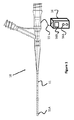
図1は、カテーテル10の細長い管状部分11を構成する構造ワイヤによって電力およびデータを送達するカテーテル10(またはあるいはマイクロカテーテル)を示す。カテーテル10は、ケーブル15を介してカテーテルにおよびカテーテルから電力および/またはデータを提供するインターフェース16に接続される。構造ワイヤが電力/データのために使用されることを可能にすることにより、カテーテルのサイズまたは直径が最小化されることができる。加えて、複数の電動コンポーネント(たとえば、センサ)およびさらには回路が、カテーテル10における遠位端11A(または他の場所)において使用されることができる。
FIG. 1 shows a catheter 10 (or microcatheter) that delivers power and data by structural wires that make up the elongated
本発明の実施形態のいくつかが、電力供給し、センサのような電気コンポーネントからデータを得るという観点で説明され得る一方で、さまざまな異なる電力供給型エレメントが可能であることが理解され得るべきである。たとえば、ヒーターコイル、機械ラッチ、および同様の電力供給型インプラント離脱メカニズムが、本発明にしたがって電力供給され得る。他の例において、他の電力供給型エレメントは、撮像システム、圧力センシング、温度センシング、および酸素センシングを含み得る。 While some of the embodiments of the invention can be described in terms of powering and obtaining data from electrical components such as sensors, it should be understood that a variety of different powering elements are possible. Is. For example, heater coils, mechanical latches, and similar powered implant detachment mechanisms can be powered according to the present invention. In other examples, other power supply elements may include imaging systems, pressure sensing, temperature sensing, and oxygen sensing.
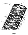
図2は、遠位に配置されたレセプタクル12によって終結し、同レセプタクル12に接続する、カテーテル10の細長い管状部分11の一部である複数の編組構造ワイヤ18を示す。これらのワイヤ18は、細長い管状部分11に構造的支持を提供し、また、カテーテル10の近位端に電気電力および/またはデータを送達するために使用され得る。図1の編組は、管状の形状に編み組まれた8つのワイヤ(18A〜18F)で構成される。編組ワイヤ18は、1)細長い管状部分11の管の外表面上、2)管状部分11の2つ以上の層の間に「サンドイッチ状にはさまれる」(すなわち、管の内部または外部に露出されない)、3)管状部分11の内部通路に露出されるように、管状部分11の内表面に沿って配置される、といった具合に、細長い管状部分11の一部としていくつかの異なる位置に配置され得る。
FIG. 2 shows a plurality of braided wire 18s that are part of an
図3Aに示す一実施形態において、編組構造ワイヤ18は、構造的にカテーテルに適した金属材料25(たとえば、ニチノールまたはステンレス鋼)であり得、高伝導層23(たとえば、金)によってコーティングされ、続いて、電気的絶縁体21(たとえば、ポリアミド)でコーティングされる。
In one embodiment shown in FIG. 3A, the
図3Bに示す別の実施形態において、管状編組を備える編組構造ワイヤ18は、電流/信号を効率的に伝達するために完全な伝導材料23(たとえば、金)で作られ、電流/信号が伝達されている間にそれの放電を防止する電気的絶縁コーティング23をさらに含む。ワイヤ18が図3Aおよび図3Bにおいて丸いまたは円形の横断面を有するものとして描かれている一方で、相対的に平らな、楕円の、長方形の、および正方形の、といった他の形状もまた可能である。
In another embodiment shown in FIG. 3B, the
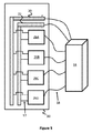
図4は、4つの電気コンポーネント(26A〜26D)および複数の構造ワイヤ18を有する例示的な回路システムの抽象的な模式図を示す。各々の電気コンポーネント26A〜26Dは、インターフェース16における電力源のプラスおよびマイナス端子に接続された2つのワイヤに接続され、インターフェース16は、それによって電気コンポーネントに電力を供給する。この点において、図2に示す8つのワイヤの例は、電気コンポーネントのすべてに電力供給し、インターフェース16にデータを通信し返すために使用され得る。同様に、各々の電気コンポーネントは回路を完成させるために2つのワイヤ18を必要とするであろうから、10個のワイヤ編組は、5つの電気コンポーネントを可能にするであろうし、16個のワイヤ編組は、8つの電気コンポーネントを可能にするであろう。この点について、2、4、6、8、10、12、14、16、および18といった任意の数のワイヤが使用され得る。
FIG. 4 shows an abstract schematic of an exemplary circuit system with four electrical components (26A-26D) and a plurality of
図5は、ワイヤ18のうち2つだけがインターフェース16のプラスおよびマイナスの電圧源(たとえば、バッテリー)を介して電力を提供する回路構成の別の実施形態を示す。ワイヤは、カテーテル10の遠位端11Aにまたは遠位端11Aの近傍に配置された分離された電気端子20および22に接続する。電気コンポーネント26A〜26Dは各々、電力がインターフェース16から電気コンポーネントの各々に供給されることを可能にするワイヤ17(または任意の他の電気経路)を介してこれらの端子20、22に接続される。
FIG. 5 shows another embodiment of a circuit configuration in which only two of the
そして、電気コンポーネント26A〜26Dの各々からのデータまたは信号は、カテーテル10の編組ワイヤ18の1つを介して電気コンポーネントからユーザインターフェースに伝達される。このように、たとえば、8つのワイヤ編組は、4つの電気コンポーネントではなく、最大6つの電気コンポーネントを利用することができる。同様に、10個のワイヤ編組は、最大8つの電気コンポーネント(プラスおよびマイナス端子接続のために使用される2つのワイヤおよび各々の電気コンポーネントに接続するために使用される残りのワイヤ)を利用し得、12個のワイヤ編組は、最大10個の電気コンポーネントを利用し得る、といった具合である。
Data or signals from each of the
(センサのような)いくつかの電気コンポーネントが(たとえば、ワイヤ上の抵抗の変化が測定されるサーミスタのように)、動作し、データを送り返すために2つの電力ワイヤのみを必要とする一方で、他の電気コンポーネントまたはセンサは、データを伝達するために1つ以上の追加のワイヤ(たとえば、全部で3つのワイヤ)を必要とする、ということが理解されるべきである。そのようなものとして、これらの実施形態の各々において使用されるワイヤの数はまた、使用される電気コンポーネントのタイプに依存する。 While some electrical components (such as sensors) (such as thermistors where changes in resistance on the wires are measured) operate and require only two power wires to send back data. It should be understood that other electrical components or sensors require one or more additional wires (eg, a total of three wires) to carry data. As such, the number of wires used in each of these embodiments also depends on the type of electrical component used.
ユーザインターフェース16は、好ましくは、ユーザがシステムの他端で結果をもたらす(たとえば、インプラントまたはカテーテル10の遠位部分11Aを離脱させる)ための制御の(たとえば、ボタン16Aを押す)ポイントとして働く。電気コンポーネントが血管の生理的状態(たとえば、圧力または温度)を感知するために使用される場合、ユーザインターフェースは、観察される特定の生理的状態を示すディスプレイ16B(ならびに基礎をなすCPU/マイクロプロセッサと、メモリと、データを処理し、ディスプレイをドライブするためのソフトウェア)を有し得る。ユーザインターフェース16はまた、好ましくは、一例ではプラスおよびマイナス端子を有するバッテリーを介した、回路のための電圧源を含む。
The
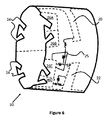
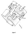
一実施形態において、図5の端子バンクおよび電気コンポーネントの構成は、図2のレセプタクル12と同様の、カテーテル10の遠位端の近傍に配置されたハイポチューブによって形成され得る。これは、図5の回路の遠位部(すなわち、端子バンク20、22および電気コンポーネント26A〜26Dを備える、図の左側)の回路の概念を採用し、それを円筒状または環状に構成することによって想像され得る。図6は、そのような回路のハイポチューブの表現30を示す。ハイポチューブ30は、編組ワイヤ18の遠位端が接続する、および/またはそうでなければその中に嵌め合う、複数の切り欠きまたは切り抜きエリア24を含む。編組のワイヤ18は、ハイポチューブ30とのぴったりフィットする接続を作成するために、切り抜きセクション24に溶接されるかまたはそうでなければ電気機械的に接合され得る。
In one embodiment, the terminal bank and electrical component configuration of FIG. 5 can be formed by hypotubes located near the distal end of the
ハイポチューブ30はまた、埋め込まれた回路25を含み得る。この回路25は、追加の機能および/または電気コンポーネント信号の処理を提供するために、電気コンポーネント26A〜26Dに接続し得る。この回路25はまた、回路25のための電力を得るために、図5におけるエレメント26によって示されているように、プラスおよびマイナスの電圧端子バンク20、22に接続され得る。
The
ハイポチューブ30は、切り抜きセクション24を含むパターンにカット(たとえば、レーザーカット)され得る。ハイポチューブ30は好ましくは、高伝導であり、高い機械的強度を有し、かつ他のワイヤおよび材料の容易な終結/接続を可能にする材料で作られる。一例において、ハイポチューブは、金めっきポリイミドで構成され、追加のレーザーカットが、異なる電気経路/回路の経路を形づくるのを助けるために行われ得る。第1の一連のカットが作成されると、ハイポチューブは、パリレンのような電気的分離材料によってコーティングされ、それはまた、レーザーカットがなされた回路の経路を接着する働きをする。パリレンは、コンフォーマルコーティング特性と高抗張力との間の釣り合いをとるが、同様の特徴を示す他の材料もまた使用され得る。追加のレーザーカットが、任意の必要な電気/回路経路を完成させるためにさらになされ得る。パリレン絶縁体はまた、ハイポチューブを一緒に把持するのを助けることができ、かくして、回路カットは、絶縁体が予備的な回路カットに追加された後に完成させられる。回路ルートが完成させられた後、パリレンコーティングがもう一度、コンポーネントを十分にカプセル化するために着手される。最後のレーザーカッティング工程が着手され、ここで、コーティングが、回路経路内のレジスタとしての追加のワイヤの追加を可能にするために重要な場所で取り除かれるかまたは除去される。この形態におけるハイポチューブ30は、従来のプリント回路基板と同様に機能する。
The
ハイポチューブ回路は、多数の目的のために使用され得る。たとえば、コンポーネントが、ユーザインターフェースではなく電気コンポーネントの箇所での信号のコンディショニングまたは処理を可能にするためにハイポチューブ30自体に追加され得る。一例において、さまざまな抵抗特性の、小さいワイヤが、センサの精度を増大させるためにホイートストンブリッジを作成するために追加され得る。演算増幅器もまた、センサ値を改善するためにハイポチューブ回路25上に統合され得る。
Hypotube circuits can be used for a number of purposes. For example, components may be added to the
ワイヤ(たとえば、カテーテルの構造編組ワイヤ18)は、信号をリレーするために近位のユーザインターフェースにセンサを接続する。信号処理または信号コンディショニングの多くは、議論される方法によってハイポチューブ回路自体の上でなされ得る。あるいはまたは加えて、信号処理はまた、ユーザインターフェース上でもなされ得る。
The wire (eg, the
ハイポチューブ30はまた、回路25の一部として、演算増幅器、信号フィルタリング、等といった多数の信号処理エレメントを含み得る。ユーザインターフェース16ではなくハイポチューブ30自体において信号処理をすることの1つの利点は、ユーザインターフェースのリソースが他の目的のために解放され得るということである。加えて、信号はある距離にわたって伝達される場合に劣化し得るので、信号がユーザインターフェース16に送り返される前にシステムの遠位部でクリーンにされることができ、かくして、システム動作への信号の劣化の影響を減じる。
The
回路の概念の1つの利点は、先に説明されたように、電気コンポーネント26の各々がインターフェース16に接続されたそれ独自のワイヤ18を有することを可能にするのではなく、回路25と電気コンポーネント26の1つ以上へのその接続とがカテーテル10の遠位部分11Aで完成させられることである。それゆえに、カテーテル管11は、相対的により小さい外径を有するように形成されることができる。
One advantage of the concept of a circuit is that it does not allow each of the electrical components 26 to have its
電気コンポーネント26は、撮像システム、圧力センシング、温度センシング、酸素センシング、または電力供給型カテーテル/マイクロカテーテルによって使用される任意の数の追加のシステムといった、多数の機能のために使用され得る。電気コンポーネントはまた、塞栓コイル離脱システム、および/または離脱可能なカテーテル先端システム、および/または操縦可能なガイドワイヤシステムの一部として使用され得る。 The electrical component 26 can be used for a number of functions, such as imaging systems, pressure sensing, temperature sensing, oxygen sensing, or any number of additional systems used by powered catheters / microcatheter. Electrical components can also be used as part of an embolic coil detachment system and / or a detachable catheter tip system and / or a maneuverable guidewire system.
図7および図8は、ハイポチューブ30の構造と同様の、ハイポチューブ32のための代替の構造を示す。この点において、ハイポチューブ32は、1つ以上の切り欠き32Aと、各々がハイポチューブ32の内方へ歪曲または湾曲させられた複数の細長い指状接点32Bとを含む。この点において、電力は接点32Bに供給され得、それは、内部のカテーテルまたはプッシャー上の電気接点との接触時に、カテーテルまたはプッシャーにヒーターまたは機械メカニズムを介してインプラントを離脱させるといった機能を行わせ得る。
7 and 8 show an alternative structure for the
図9Aおよび図9Bは、引用によってここに組み込まれる米国出願番号第14/578,106号において開示されたものと同様の塞栓コイル42を離脱させるために使用される接点32Bを有するハイポチューブ32の1つの例示的な使用を示す。ハイポチューブ32は、1つ以上の遠位または近位の接点32Bにそれぞれが接続された、遠位の電力端子20と近位の端子22とを含む。塞栓コイル42は、コイル42に沿った選択場所に、1つ以上の離脱ポイント44を有する。電気接点32Bが塞栓コイル42および離脱ポイント44とアラインメントする際、インターフェース16は、アラインメントを示すかまたは表示し得る。ユーザがアラインメント信号を受信すると、プッシャー40からの離脱ゾーン44でのコイル42の離脱を開始するためにボタンを押すといった所望のアクションがアクチュエートされ得る。ハイポチューブ32は複数の電動コンポーネントを支持し得るので、離脱検出、温度センシング、または撮像といった機能を提供するセンサ32Cもまた、ハイポチューブ32上に含まれることができる。
9A and 9B show a
図10および図11は、塞栓コイルの離脱ポイント44のより具体的な例を示す。2つの伝導シリンダまたはスリーブ54および55が、粘着剤または糊着剤によって絶縁スリーブ56の近位および遠位端に嵌め合わせられる。伝導スリーブ54および55は、92/8の比のプラチナ/タングステン材料のような伝導材料で構成される。
10 and 11 show more specific examples of the
ワイヤのコイルであり得るヒーター60は、近位および遠位の伝導スリーブ54および55の間のエリアにわたり、その端をスリーブの各々に接続し、電流がコンポーネントの各々を通過することを可能にする。それゆえに、ハイポチューブ32の近位および遠位の接点32Bと適切にアラインメントさせられ、電流が印加された場合、ヒーターコイル60は、温度が上昇し、絶縁スリーブの粘着剤を溶解し、塞栓コイル42の遠位部分を離脱させる。ばね57および58は、塞栓コイルの伸張を防止するのを助けるためにモノフィラメントまたは紐の取り付けを可能にする。代替の実施形態では、紐が、塞栓コイル42の2つのセグメントを一緒に把持するように2つのばね57、58の間を接続し得、したがって、離脱を引き起こすためにヒーター60によって解体され得る。
The
第14/578,106号に開示された例と同様の別の一例において、操縦可能なガイドワイヤシステムは、血管系の中のバイメタルガイドワイヤの走行を可能にするためにガイドワイヤの遠位端を歪曲させるためにガイドワイヤと電気的にインタラクトする、図9Aおよび図9Bにおいて説明されたものと同様の、ハイポチューブ上の間隔をあけられたプラスとマイナスの電気接点を利用する。 In another example similar to the example disclosed in No. 14 / 578,106, the steerable guidewire system is the distal end of the guidewire to allow the bimetal guidewire to travel within the vascular system. It utilizes spaced positive and negative electrical contacts on the hypotube, similar to those described in FIGS. 9A and 9B, which electrically interact with the guide wire to distort the.
先に議論されたように、ハイポチューブ30およびその回路は、カテーテル10におけるヒーターコイルに電力供給するために使用され得る。一例において、図12および図13は、米国出願番号第14/578,020号において開示され、引用によってここに組み込まれる実施形態と同様の離脱可能な遠位端の先端11Aを有するカテーテル10を開示する。ハイポチューブ30が、細長い管状部分11の遠位部分に配置され、粘着剤48が、細長い管状部分11に対し遠位端の先端11Aを維持する。ユーザは、離脱シーケンスを開始(たとえば、インターフェース16上のボタンを押下)してヒーター49をアクティブにすることができ、さまざまな理由のために(たとえば、カテーテルの遠位の先端11Aが血管系の中に糊着される危険が存在する液体塞栓のデリバリー中に)、マイクロカテーテル10の遠位端の先端11Aの離脱をもたらすために粘着剤48を溶解する。前出の例と同様に、ハイポチューブ30は、編組構造ワイヤ18に接続し、ヒーター49に電気経路を提供する。この例において、ヒーター49は、ハイポチューブ30の内表面に隣接して配置されることも、またはハイポチューブ30の内表面に接続されることさえもできる。
As discussed earlier, the
図14は、図13のハイポチューブ30の代替の実施形態を示すが、単一のヒーター49に接続するのではなく、ハイポチューブ30は、近位のヒーターコイル49A、中央のヒーターコイル49B、および遠位のヒーターコイル49Cに接続する。ハイポチューブ30は、ワイヤ18の3つの離散ペアおよびハイポチューブ30上の電気経路に接続され得、ヒーターコイルの各々が個々にアクティブされることを可能にする。
FIG. 14 shows an alternative embodiment of the
図15は、コイルが互いにパラレルにかつ隣接して配置される点を除き図14のハイポチューブと同様の、複数のヒーターコイル49を有するハイポチューブ30を示す。この点において、ハイポチューブ30は、カテーテルの中に、またはカテーテル内の移動のためのサイズにされたプッシャー内に、のいずれかで配置され得る。
FIG. 15 shows a
あるいは、ユーザインターフェースは、複数のバッテリーを含み得、複数のバッテリーに接続されたハイポチューブ上の複数の端子バンクを可能にする。別の代替例では、複数のバッテリーが使用され、1つのバッテリーに端子バンクの提供を可能にさせ、他のバッテリーは、特定のシステムのために選択的に使用される(すなわち、可変コイル離脱システムのための端子に電力供給するためにだけ使用される1つのバッテリー、および/または、離脱可能な先端カテーテルシステムのための端子に電力供給するためにだけ使用される1つのバッテリー)。かくして、たとえば、異なるシステムとインタラクトするために異なる間隔で間隔をあけられた1つのプラス接点および2つのマイナス接点が存在し得る。同様に、異なるシステムとインタラクトするために異なる間隔で間隔をあけられた1つのマイナス接点および2つのプラス接点が存在し得る。一例において、電気コンポーネントは、先に議論されているように、ハイポチューブ上の集積回路と、ワイヤ編組を介してユーザインターフェースに送られる信号とによって、使用中の精密なシステム(すなわち、可変離脱具、離脱可能な先端、操縦可能なガイドワイヤ、または別のシステム)の動作を制御し得る。別の例において、編組ワイヤが電気コンポーネントからの信号と反対にバッテリーからの電流を伝達するためにだけ使用される場合、遠位のハイポチューブの電気コンポーネントは不要であろう。この例では、ユーザインターフェース自体がさまざまなシステムのための回路を有するであろうし、カテーテルの近位端と遠位端との間で電流を伝達するために使用されるワイヤはまた、ユーザインターフェースからの信号を伝達する(すなわち、塞栓コイルを離脱させるために、またはカテーテルの先端を離脱させるために、またはガイドワイヤの先端をそらせるために入力された信号を伝達する)ためにも使用される。 Alternatively, the user interface may include multiple batteries, allowing multiple terminal banks on hypotubes connected to multiple batteries. In another alternative, multiple batteries are used, allowing one battery to provide a terminal bank, the other battery being selectively used for a particular system (ie, variable coil detachment system). One battery used only to power the terminals for, and / or one battery used only to power the terminals for the removable tip catheter system). Thus, for example, there can be one positive contact and two negative contacts spaced at different intervals to interact with different systems. Similarly, there can be one negative contact and two positive contacts spaced at different intervals to interact with different systems. In one example, the electrical component is a precision system in use (ie, a variable release tool) by means of integrated circuits on hypotubes and signals sent to the user interface via wire braids, as discussed earlier. , Detachable tip, steerable guidewire, or another system) can be controlled. In another example, if the braided wire is used only to carry current from the battery as opposed to the signal from the electrical component, the electrical component of the distal hypotube would not be needed. In this example, the user interface itself would have circuits for various systems, and the wires used to transfer current between the proximal and distal ends of the catheter would also be from the user interface. It is also used to transmit the signal (ie, to disengage the embolizing coil, to disengage the tip of the catheter, or to distract the tip of the guide wire).
ここで説明された実施形態およびシステムは、電力供給型カテーテルシステムを作成することにおける多くの利点を提供する。以下は、網羅的ではない一覧である。システムの主な利点の1つは、電流を伝達するためにカテーテル編組自体を使用すること、かくして、カテーテルの構造的補強に加えて、カテーテル編組に、有用な二次的な恩典を提供することである。システムの別の利点は、カテーテルの遠位端のハイポチューブ上の端子バンクに電力供給するためにカテーテル編組ワイヤの2つを使用すること、電気コンポーネントをハイポチューブ自体の上で端子バンクに直接接続させること、かくして、電気コンポーネントがハイポチューブ自体の上で電力供給されるがゆえにユーザインターフェースに電気コンポーネントを接続するために1つのワイヤしか必要としないことである。システムの別の利点は、遠位のハイポチューブを回路システムとして利用すること、および、信号処理がシステムの近位端ではなく集積回路を介してハイポチューブ自体の上でなされることを可能にする能力である。信号は長距離にわたって劣化し得るので、信号源での信号処理を提供することは、それ自体におけるおよびそれ自体のいくつかの利点を提供する。別の利点は、すべての信号を伝達するために多数のワイヤを必要とせずにいくつかの電力供給型カテーテル機能を組み合わせる能力である。 The embodiments and systems described herein offer many advantages in creating a powered catheter system. The following is a non-exhaustive list. One of the main advantages of the system is the use of the catheter braid itself to carry the current, thus providing a useful secondary benefit to the catheter braid, in addition to the structural reinforcement of the catheter. Is. Another advantage of the system is the use of two of the catheter braided wires to power the terminal bank on the hypotube at the distal end of the catheter, connecting the electrical components directly to the terminal bank on the hypotube itself. That is, thus, because the electrical component is powered on the hypotube itself, only one wire is needed to connect the electrical component to the user interface. Another advantage of the system is that it allows the distal hypotube to be utilized as a circuit system and that signal processing is done on the hypotube itself via an integrated circuit rather than at the proximal end of the system. Ability. Since the signal can be degraded over long distances, providing signal processing at the signal source provides some advantages in itself and in itself. Another advantage is the ability to combine several powered catheter functions without the need for multiple wires to carry all signals.
他の実施形態において、ここで説明されたシステムは、別個のマイナス端子源を必要としないであろうし、患者自身が、回路を完成させるために接地として使用され得るだろう。かくして、一例において、システムの近位部は、単にプラスの荷電源を含むだけであろうし、ワイヤがシステムの遠位端に電流を走らせるであろうし、患者自身が接地を備えるであろう。システムの遠位端はさらに、電気コンポーネントとともにすべての回路を利用するであろうが、これは、患者が接地を提供するがゆえに1つのワイヤだけが電流を伝達するために必要とされるであろうから、追加の電気コンポーネントを可能にするであろう。 In other embodiments, the system described herein would not require a separate negative terminal source and could be used by the patient himself as a ground to complete the circuit. Thus, in one example, the proximal part of the system would simply contain a positive load power source, the wires would run current to the distal end of the system, and the patient himself would be grounded. The distal end of the system will also utilize all the circuits along with the electrical components, which would be required for only one wire to carry current because the patient provides grounding. From wax, it will allow for additional electrical components.
他の実施形態において、代替の電流電圧源が、直流電圧源の代わりに使用され得る。 In other embodiments, an alternative current voltage source may be used in place of the DC voltage source.
他の実施形態では、カテーテルシステムのための配線は、カテーテル編組を利用しないであろうが(すなわち、カテーテルが何ら編組を利用しない場合)、カテーテルの表面の外部または内部であるかまたはカテーテル管の層の間に統合されたワイヤからなる。他の実施形態では、補強コイル(単数または複数)またはリボン(単数または複数)が編組の代わりに使用され得る。 In other embodiments, the wiring for the catheter system will not utilize a catheter braid (ie, if the catheter does not utilize any braid), but is outside or inside the surface of the catheter or of the catheter tube. It consists of wires integrated between the layers. In other embodiments, reinforcing coils (s) or ribbons (s) may be used instead of braids.
他の実施形態において、端子バンクは、コンデンサと置き換えられ得る。そして、コンデンサは、電圧源からの荷電を貯蔵し得る。 In other embodiments, the terminal bank can be replaced with a capacitor. The capacitor can then store the charge from the voltage source.
説明された実施形態は、回路システムを含む。回路システムは、カテーテル、またはマイクロカテーテル、または他のデリバリーデバイスを含む、介入デバイスを含む多数のデバイス上で使用され得る。 The embodiments described include a circuit system. The circuit system can be used on a number of devices, including intervention devices, including catheters, or microcatheter, or other delivery devices.
説明された実施形態は、カテーテルの二端の間で電流を伝導するためにカテーテルの構造補強層(編組として一般的に説明される)を利用する。編組という用語が使用されるが、用語は任意の構造層を説明するように広く解釈されるべきであり、かくして、編組という用語は、コイル、リボン、およびカテーテルにおいて一般に使用される他の構造コンポーネントを含み得る。 The embodiments described utilize a structural reinforcement layer (generally described as braid) of the catheter to conduct current between the two ends of the catheter. Although the term braid is used, the term should be broadly interpreted to describe any structural layer, thus the term braid is used for coils, ribbons, and other structural components commonly used in catheters. May include.
発明は特定の実施形態および応用例の観点で説明されているが、当業者は、この教示に鑑みて、特許請求される発明の精神から逸脱もせず、特許請求される発明の範囲を超えることもなく、追加の実施形態および変更例を生み出し得る。したがって、ここでの図面および説明は、発明の理解を容易にするために例として提供されたものであり、その範囲を限定するように解釈されるべきではない、ということが理解されるべきである。 Although the invention is described in terms of specific embodiments and applications, those skilled in the art will not deviate from the spirit of the claimed invention in view of this teaching and will be beyond the scope of the claimed invention. Without it, additional embodiments and modifications can be produced. Therefore, it should be understood that the drawings and description herein are provided as examples to facilitate the understanding of the invention and should not be construed to limit its scope. is there.
Claims (14)
前記近位端と前記遠位端との間で延伸する複数のワイヤと、
前記細長い管状部分の前記遠位端に配置されたハイポチューブであって、前記複数のワイヤと該ハイポチューブとの間でぴったりフィットする接続を作成するために、前記複数のワイヤの1つ以上の遠位端に接合された複数の切り欠きエリアであって前記ハイポチューブの近位端を貫通する切り抜き部分によって形成された該切り欠きエリアを含む近位端を有するハイポチューブと、
前記ハイポチューブに接続され、複数の電気経路の1つ以上と電気通信している1つ以上の電動コンポーネントと、
前記複数のワイヤの少なくとも2つを介して前記ハイポチューブに電力を供給するように前記細長い管状部分の前記近位端に接続可能なインターフェースと
を具備するカテーテル。 An elongated tubular portion having a proximal end, a distal end, and a lumen straddling the proximal end and the distal end,
A plurality of wires extending between the proximal end and the distal end,
A hypotube located at the distal end of the elongated tubular portion, one or more of the plurality of wires to create a snug-fitting connection between the plurality of wires and the hypotube. A hypotube having a plurality of cutout areas joined to the distal end and having a proximal end including the cutout area formed by a cutout portion penetrating the proximal end of the hypotube.
One or more electrical components connected to the hypotube and telecommunications with one or more of the plurality of electrical paths.
A catheter comprising an interface that can be connected to the proximal end of the elongated tubular portion to power the hypotube via at least two of the plurality of wires.
前記細長い管状部分の前記遠位端に配置され、1つ以上の電気経路を形成するハイポチューブであって、該ハイポチューブの近位端を貫通する切り抜き部分によって形成された複数の切り欠きエリアを有するハイポチューブと、
前記ハイポチューブに接続され、前記電気経路の1つ以上と電気通信している1つ以上の電動コンポーネントと、
前記複数の編組ワイヤの少なくとも2つを介して前記ハイポチューブに電力を供給するように前記細長い管状部分の前記近位端に接続可能なインターフェースであって、前記細長い管状部分にまたがる前記複数の編組ワイヤの少なくとも2つの遠位端は、前記ハイポチューブの近位端で前記切り欠きエリアのうちの1つにそれぞれ接続されるインターフェースと
を具備するカテーテル。 A plurality of elongated tubular portions having a proximal end, a distal end, and a lumen straddling the proximal end and the distal end, extending between the proximal end and the distal end. With an elongated tubular part containing braided wires ,
A hypotube located at the distal end of the elongated tubular portion and forming one or more electrical pathways, with a plurality of notched areas formed by cutouts penetrating the proximal end of the hypotube. Hypotube to have
With one or more electric components connected to the hypotube and telecommunications with one or more of the electrical paths.
An interface that is connectable to the proximal end of the elongated tubular portion so as to power the hypotube via at least two of the plurality of braided wires, the plurality of braids straddling the elongated tubular portion. A catheter comprising an interface in which at least two distal ends of a wire are respectively connected to one of the notched areas at the proximal end of the hypotube.
Applications Claiming Priority (3)
| Application Number | Priority Date | Filing Date | Title |
|---|---|---|---|
| US201562168525P | 2015-05-29 | 2015-05-29 | |
| US62/168,525 | 2015-05-29 | ||
| PCT/US2016/035106 WO2016196519A1 (en) | 2015-05-29 | 2016-05-31 | Catheter circuit |
Publications (3)
| Publication Number | Publication Date |
|---|---|
| JP2018524130A JP2018524130A (en) | 2018-08-30 |
| JP2018524130A5 JP2018524130A5 (en) | 2019-08-22 |
| JP6812422B2 true JP6812422B2 (en) | 2021-01-13 |
Family
ID=57397900
Family Applications (1)
| Application Number | Title | Priority Date | Filing Date |
|---|---|---|---|
| JP2018514943A Active JP6812422B2 (en) | 2015-05-29 | 2016-05-31 | Catheter circuit |
Country Status (5)
| Country | Link |
|---|---|
| US (2) | US11229402B2 (en) |
| EP (2) | EP3302676B1 (en) |
| JP (1) | JP6812422B2 (en) |
| CN (2) | CN107614049B (en) |
| WO (1) | WO2016196519A1 (en) |
Families Citing this family (21)
| Publication number | Priority date | Publication date | Assignee | Title |
|---|---|---|---|---|
| US9265512B2 (en) | 2013-12-23 | 2016-02-23 | Silk Road Medical, Inc. | Transcarotid neurovascular catheter |
| US10426497B2 (en) | 2015-07-24 | 2019-10-01 | Route 92 Medical, Inc. | Anchoring delivery system and methods |
| ES2932764T3 (en) | 2015-02-04 | 2023-01-26 | Route 92 Medical Inc | Rapid Aspiration Thrombectomy System |
| US11065019B1 (en) | 2015-02-04 | 2021-07-20 | Route 92 Medical, Inc. | Aspiration catheter systems and methods of use |
| EP3419528B1 (en) | 2016-02-24 | 2023-06-07 | Incept, LLC | Enhanced flexibility neurovascular catheter |
| JP7264581B2 (en) | 2017-01-06 | 2023-04-25 | インセプト、リミテッド、ライアビリティ、カンパニー | Antithrombotic coating for aneurysm treatment devices |
| EP3568186B1 (en) | 2017-01-10 | 2022-09-14 | Route 92 Medical, Inc. | Aspiration catheter systems |
| WO2018156639A1 (en) | 2017-02-21 | 2018-08-30 | Microvention, Inc. | Electrical catheter |
| US11039840B2 (en) * | 2017-12-11 | 2021-06-22 | Microvention, Inc. | Implant detachment |
| US11395665B2 (en) | 2018-05-01 | 2022-07-26 | Incept, Llc | Devices and methods for removing obstructive material, from an intravascular site |
| CN112203593A (en) | 2018-05-01 | 2021-01-08 | 因赛普特有限责任公司 | Device and method for removing occlusive material from an intravascular site |
| JP2021523793A (en) | 2018-05-17 | 2021-09-09 | ルート92メディカル・インコーポレイテッドRoute 92 Medical, Inc. | Suction catheter system and how to use |
| US11517335B2 (en) | 2018-07-06 | 2022-12-06 | Incept, Llc | Sealed neurovascular extendable catheter |
| US11471582B2 (en) | 2018-07-06 | 2022-10-18 | Incept, Llc | Vacuum transfer tool for extendable catheter |
| US11766539B2 (en) | 2019-03-29 | 2023-09-26 | Incept, Llc | Enhanced flexibility neurovascular catheter |
| CN113347916A (en) | 2019-10-15 | 2021-09-03 | 因普瑞缇夫护理公司 | System and method for multivariate stroke detection |
| US11259821B2 (en) | 2019-12-18 | 2022-03-01 | Imperative Care, Inc. | Aspiration system with accelerated response |
| JP2023507553A (en) | 2019-12-18 | 2023-02-24 | インパラティブ、ケア、インク. | Methods and systems for treating venous thromboembolism |
| US11633272B2 (en) | 2019-12-18 | 2023-04-25 | Imperative Care, Inc. | Manually rotatable thrombus engagement tool |
| AU2021235887A1 (en) | 2020-03-10 | 2022-09-08 | Imperative Care, Inc. | Enhanced flexibility neurovascular catheter |
| US11207497B1 (en) | 2020-08-11 | 2021-12-28 | Imperative Care, Inc. | Catheter with enhanced tensile strength |
Family Cites Families (52)
| Publication number | Priority date | Publication date | Assignee | Title |
|---|---|---|---|---|
| JPS5921495B2 (en) | 1977-12-15 | 1984-05-21 | 株式会社豊田中央研究所 | Capillary pressure gauge |
| US4484586A (en) | 1982-05-27 | 1984-11-27 | Berkley & Company, Inc. | Hollow conductive medical tubing |
| US5706809A (en) * | 1993-01-29 | 1998-01-13 | Cardima, Inc. | Method and system for using multiple intravascular sensing devices to detect electrical activity |
| NL9300670A (en) * | 1993-04-20 | 1994-11-16 | Cordis Europ | Catheter with electrically conductive wire reinforcement. |
| US5555618A (en) * | 1993-10-12 | 1996-09-17 | Arrow International Investment Corp. | Method of making electrode-carrying catheter |
| US5522836A (en) | 1994-06-27 | 1996-06-04 | Target Therapeutics, Inc. | Electrolytically severable coil assembly with movable detachment point |
| JPH09140802A (en) * | 1995-11-21 | 1997-06-03 | Nippon Zeon Co Ltd | Electrode catheter |
| US7052493B2 (en) * | 1996-10-22 | 2006-05-30 | Epicor Medical, Inc. | Methods and devices for ablation |
| US5935124A (en) * | 1997-12-02 | 1999-08-10 | Cordis Webster, Inc. | Tip electrode with multiple temperature sensors |
| US5941888A (en) * | 1998-02-18 | 1999-08-24 | Target Therapeutics, Inc. | Vaso-occlusive member assembly with multiple detaching points |
| JP2000116786A (en) * | 1998-10-12 | 2000-04-25 | Terumo Corp | Production of in-vivo inserter having electric conduction path |
| US6210339B1 (en) | 1999-03-03 | 2001-04-03 | Endosonics Corporation | Flexible elongate member having one or more electrical contacts |
| US6511478B1 (en) * | 2000-06-30 | 2003-01-28 | Scimed Life Systems, Inc. | Medical probe with reduced number of temperature sensor wires |
| EP1486077A4 (en) | 2002-03-18 | 2008-03-26 | Sarcos Invest Lc | Miniaturized imaging device |
| US7787939B2 (en) * | 2002-03-18 | 2010-08-31 | Sterling Lc | Miniaturized imaging device including utility aperture and SSID |
| US7591780B2 (en) * | 2002-03-18 | 2009-09-22 | Sterling Lc | Miniaturized imaging device with integrated circuit connector system |
| EP1692457A4 (en) * | 2003-12-11 | 2007-09-26 | Proteus Biomedical Inc | Implantable pressure sensors |
| US7720521B2 (en) * | 2004-04-21 | 2010-05-18 | Acclarent, Inc. | Methods and devices for performing procedures within the ear, nose, throat and paranasal sinuses |
| US8845676B2 (en) | 2004-09-22 | 2014-09-30 | Micro Therapeutics | Micro-spiral implantation device |
| US8277386B2 (en) * | 2004-09-27 | 2012-10-02 | Volcano Corporation | Combination sensor guidewire and methods of use |
| CN101048107A (en) * | 2004-10-29 | 2007-10-03 | 株式会社钟化 | Medical wire |
| WO2006050385A2 (en) * | 2004-11-01 | 2006-05-11 | Proteus Biomedical, Inc. | Cardiac motion characterization by strain measurement |
| US20060149129A1 (en) * | 2005-01-05 | 2006-07-06 | Watts H D | Catheter with multiple visual elements |
| US20060217791A1 (en) * | 2005-03-23 | 2006-09-28 | Arrow International, Inc. | Multi-lumen catheter having external electrical leads |
| JP4648063B2 (en) | 2005-04-19 | 2011-03-09 | 日東電工株式会社 | Flexible wiring circuit board for catheter, catheter using the flexible wiring circuit board, and manufacturing method thereof |
| US7879030B2 (en) | 2005-07-27 | 2011-02-01 | St. Jude Medical, Atrial Fibrillation Division, Inc. | Multipolar, virtual-electrode catheter with at least one surface electrode and method for ablation |
| US7778684B2 (en) * | 2005-08-08 | 2010-08-17 | Boston Scientific Scimed, Inc. | MRI resonator system with stent implant |
| US8062267B2 (en) * | 2006-10-05 | 2011-11-22 | Becton, Dickinson And Company | Vascular access device including a tear-resistant septum |
| WO2008045877A2 (en) | 2006-10-10 | 2008-04-17 | St. Jude Medical, Atrial Fibrillation Division, Inc. | Electrode tip and ablation system |
| EP2444010B1 (en) * | 2007-05-18 | 2017-03-01 | Stryker European Holdings I, LLC | Medical implant detachment systems |
| EP2231030B1 (en) * | 2007-12-21 | 2019-02-27 | MicroVention, Inc. | System and method for locating detachment zone of a detachable implant |
| EP2240093B1 (en) | 2008-01-04 | 2013-04-24 | Boston Scientific Scimed, Inc. | Detachment mechanisms for implantable devices |
| DE102008003341B4 (en) * | 2008-01-07 | 2021-07-01 | Robert Bosch Gmbh | Sensor device |
| US8016799B2 (en) | 2008-04-22 | 2011-09-13 | Medtronic Vascular, Inc. | Catheter having a detachable tip |
| US8734437B2 (en) * | 2008-07-23 | 2014-05-27 | Boston Scientific Scimed, Inc. | Catheter having electrically conductive pathways |
| EP2349431B1 (en) | 2008-08-19 | 2015-01-21 | Covidien LP | Detachable tip microcatheter |
| US8359105B2 (en) | 2008-08-27 | 2013-01-22 | Boston Scientific Scimed, Inc. | Electrically conductive pathways in medical devices |
| CA2739603A1 (en) * | 2008-10-13 | 2010-04-22 | Stryker Corporation | Vaso-occlusive coil delivery system |
| US20120215133A1 (en) * | 2011-02-22 | 2012-08-23 | Brad Jeffrey Neiman | Catheter tip device and method for manufacturing same |
| US9734938B2 (en) * | 2011-10-06 | 2017-08-15 | 3Dt Holdings, Llc | Devices and systems for obtaining conductance data and methods of manufacturing and using the same |
| US8932318B2 (en) * | 2012-03-30 | 2015-01-13 | DePuy Synthes Products, LLC | Embolic coil detachment mechanism with polymer tether |
| US8888788B2 (en) * | 2012-08-06 | 2014-11-18 | Shockwave Medical, Inc. | Low profile electrodes for an angioplasty shock wave catheter |
| WO2014025255A1 (en) * | 2012-08-06 | 2014-02-13 | Wellinq Medical B.V. | Pressure sensor catheter and associated method |
| CN103110414A (en) * | 2012-12-21 | 2013-05-22 | 西安交通大学 | Full-bridge chip embedded skull pressure sensor |
| USRE49433E1 (en) * | 2013-02-05 | 2023-02-28 | Handock Inc. | Catheter for denervation |
| US9615760B2 (en) * | 2013-06-17 | 2017-04-11 | Biosense Webster (Israel), Ltd. | Multiple bipolar sampling |
| IL234511B (en) * | 2013-10-25 | 2020-08-31 | Biosense Webster Israel Ltd | Connection of electrodes to wires coiled on a core |
| US11890025B2 (en) * | 2013-11-18 | 2024-02-06 | Philips Image Guided Therapy Corporation | Guided thrombus dispersal catheter |
| WO2015095798A1 (en) * | 2013-12-20 | 2015-06-25 | Microvention, Inc. | Catheter system |
| US9480416B2 (en) | 2014-01-17 | 2016-11-01 | Biosense Webster (Israel) Ltd. | Signal transmission using catheter braid wires |
| AU2015210763B2 (en) * | 2014-01-30 | 2019-11-28 | 3Dt Holdings, Llc | Luminal impedance device with integrated circuit modules |
| CN203971119U (en) * | 2014-06-27 | 2014-12-03 | 王海鸥 | A kind of tracheal intubation |
-
2016
- 2016-05-31 JP JP2018514943A patent/JP6812422B2/en active Active
- 2016-05-31 US US15/169,588 patent/US11229402B2/en active Active
- 2016-05-31 CN CN201680029714.2A patent/CN107614049B/en active Active
- 2016-05-31 EP EP16804263.8A patent/EP3302676B1/en active Active
- 2016-05-31 EP EP23174406.1A patent/EP4233738A3/en active Pending
- 2016-05-31 CN CN202110510520.7A patent/CN113209449B/en active Active
- 2016-05-31 WO PCT/US2016/035106 patent/WO2016196519A1/en active Application Filing
-
2021
- 2021-12-14 US US17/644,317 patent/US20220104770A1/en active Pending
Also Published As
| Publication number | Publication date |
|---|---|
| US20220104770A1 (en) | 2022-04-07 |
| EP3302676B1 (en) | 2023-07-12 |
| EP3302676A1 (en) | 2018-04-11 |
| CN113209449B (en) | 2023-04-18 |
| CN113209449A (en) | 2021-08-06 |
| JP2018524130A (en) | 2018-08-30 |
| WO2016196519A1 (en) | 2016-12-08 |
| CN107614049A (en) | 2018-01-19 |
| EP4233738A3 (en) | 2023-10-18 |
| EP4233738A2 (en) | 2023-08-30 |
| EP3302676A4 (en) | 2019-02-13 |
| CN107614049B (en) | 2021-06-04 |
| US20160345904A1 (en) | 2016-12-01 |
| US11229402B2 (en) | 2022-01-25 |
Similar Documents
| Publication | Publication Date | Title |
|---|---|---|
| JP6812422B2 (en) | Catheter circuit | |
| JP6359664B2 (en) | Vascular occlusive device delivery system | |
| US5843076A (en) | Catheter with an electromagnetic guidance sensor | |
| US8398671B2 (en) | Electrical contact for occlusive device delivery system | |
| US9265504B2 (en) | Vaso-occlusive coil delivery system | |
| US9572508B2 (en) | In-plane dual loop fixed diameter electrophysiology catheters and methods of manufacturing therefor | |
| US9050105B2 (en) | Catheter with multiple irrigated electrodes and a force sensor | |
| KR102185937B1 (en) | Contact force sensor | |
| US9314250B2 (en) | Electrical contact for occlusive device delivery system | |
| CN106413537B (en) | Catheter shaft with conductive traces | |
| US20100234872A1 (en) | Electrical contact for occlusive device delivery system | |
| WO2010120653A1 (en) | Delivery wire for occlusive device delivery system and method of manufacture | |
| US20110106098A1 (en) | Occlusive device delivery system | |
| US20140187972A1 (en) | Guidewire Devices and Methods | |
| JP7416759B2 (en) | Flexible circuit tip for split tip catheters | |
| JP5339630B2 (en) | Electrode catheter |
Legal Events
| Date | Code | Title | Description |
|---|---|---|---|
| A621 | Written request for application examination |
Free format text: JAPANESE INTERMEDIATE CODE: A621 Effective date: 20190530 |
|
| A521 | Request for written amendment filed |
Free format text: JAPANESE INTERMEDIATE CODE: A523 Effective date: 20190710 |
|
| A977 | Report on retrieval |
Free format text: JAPANESE INTERMEDIATE CODE: A971007 Effective date: 20200527 |
|
| A131 | Notification of reasons for refusal |
Free format text: JAPANESE INTERMEDIATE CODE: A131 Effective date: 20200616 |
|
| A521 | Request for written amendment filed |
Free format text: JAPANESE INTERMEDIATE CODE: A523 Effective date: 20200914 |
|
| TRDD | Decision of grant or rejection written | ||
| A01 | Written decision to grant a patent or to grant a registration (utility model) |
Free format text: JAPANESE INTERMEDIATE CODE: A01 Effective date: 20201124 |
|
| A61 | First payment of annual fees (during grant procedure) |
Free format text: JAPANESE INTERMEDIATE CODE: A61 Effective date: 20201216 |
|
| R150 | Certificate of patent or registration of utility model |
Ref document number: 6812422 Country of ref document: JP Free format text: JAPANESE INTERMEDIATE CODE: R150 |
|
| R250 | Receipt of annual fees |
Free format text: JAPANESE INTERMEDIATE CODE: R250 |