JP6804773B2 - Subject visualization device - Google Patents
Subject visualization device Download PDFInfo
- Publication number
- JP6804773B2 JP6804773B2 JP2018524032A JP2018524032A JP6804773B2 JP 6804773 B2 JP6804773 B2 JP 6804773B2 JP 2018524032 A JP2018524032 A JP 2018524032A JP 2018524032 A JP2018524032 A JP 2018524032A JP 6804773 B2 JP6804773 B2 JP 6804773B2
- Authority
- JP
- Japan
- Prior art keywords
- light
- stokes
- wavelength
- stokes light
- pump
- Prior art date
- Legal status (The legal status is an assumption and is not a legal conclusion. Google has not performed a legal analysis and makes no representation as to the accuracy of the status listed.)
- Active
Links
- 238000012800 visualization Methods 0.000 title claims description 33
- 238000012360 testing method Methods 0.000 claims description 114
- 230000003287 optical effect Effects 0.000 claims description 91
- 239000013078 crystal Substances 0.000 claims description 28
- 230000003595 spectral effect Effects 0.000 claims description 19
- 238000000034 method Methods 0.000 claims description 18
- 238000012545 processing Methods 0.000 claims description 12
- 238000007689 inspection Methods 0.000 claims description 10
- 230000008569 process Effects 0.000 claims description 10
- 238000006243 chemical reaction Methods 0.000 claims description 9
- WQZGKKKJIJFFOK-GASJEMHNSA-N Glucose Natural products OC[C@H]1OC(O)[C@H](O)[C@@H](O)[C@@H]1O WQZGKKKJIJFFOK-GASJEMHNSA-N 0.000 claims description 8
- 239000008103 glucose Substances 0.000 claims description 8
- KBPHJBAIARWVSC-RGZFRNHPSA-N lutein Chemical compound C([C@H](O)CC=1C)C(C)(C)C=1\C=C\C(\C)=C\C=C\C(\C)=C\C=C\C=C(/C)\C=C\C=C(/C)\C=C\[C@H]1C(C)=C[C@H](O)CC1(C)C KBPHJBAIARWVSC-RGZFRNHPSA-N 0.000 claims description 8
- 229960005375 lutein Drugs 0.000 claims description 8
- ORAKUVXRZWMARG-WZLJTJAWSA-N lutein Natural products CC(=C/C=C/C=C(C)/C=C/C=C(C)/C=C/C1=C(C)CCCC1(C)C)C=CC=C(/C)C=CC2C(=CC(O)CC2(C)C)C ORAKUVXRZWMARG-WZLJTJAWSA-N 0.000 claims description 8
- 235000012680 lutein Nutrition 0.000 claims description 8
- 239000001656 lutein Substances 0.000 claims description 8
- KBPHJBAIARWVSC-XQIHNALSSA-N trans-lutein Natural products CC(=C/C=C/C=C(C)/C=C/C=C(C)/C=C/C1=C(C)CC(O)CC1(C)C)C=CC=C(/C)C=CC2C(=CC(O)CC2(C)C)C KBPHJBAIARWVSC-XQIHNALSSA-N 0.000 claims description 8
- FJHBOVDFOQMZRV-XQIHNALSSA-N xanthophyll Natural products CC(=C/C=C/C=C(C)/C=C/C=C(C)/C=C/C1=C(C)CC(O)CC1(C)C)C=CC=C(/C)C=CC2C=C(C)C(O)CC2(C)C FJHBOVDFOQMZRV-XQIHNALSSA-N 0.000 claims description 8
- 238000010586 diagram Methods 0.000 description 12
- 230000010355 oscillation Effects 0.000 description 11
- 208000037265 diseases, disorders, signs and symptoms Diseases 0.000 description 8
- 238000003384 imaging method Methods 0.000 description 8
- 238000012014 optical coherence tomography Methods 0.000 description 7
- 201000010099 disease Diseases 0.000 description 6
- 230000005284 excitation Effects 0.000 description 6
- 210000005252 bulbus oculi Anatomy 0.000 description 5
- 210000000695 crystalline len Anatomy 0.000 description 4
- 210000001525 retina Anatomy 0.000 description 4
- 239000000523 sample Substances 0.000 description 4
- 206010064930 age-related macular degeneration Diseases 0.000 description 3
- 208000002780 macular degeneration Diseases 0.000 description 3
- 230000007246 mechanism Effects 0.000 description 3
- 230000010287 polarization Effects 0.000 description 3
- 238000010408 sweeping Methods 0.000 description 3
- 238000001069 Raman spectroscopy Methods 0.000 description 2
- 230000001427 coherent effect Effects 0.000 description 2
- 125000002791 glucosyl group Chemical group C1([C@H](O)[C@@H](O)[C@H](O)[C@H](O1)CO)* 0.000 description 2
- 230000001678 irradiating effect Effects 0.000 description 2
- 238000005259 measurement Methods 0.000 description 2
- 230000000877 morphologic effect Effects 0.000 description 2
- 230000004660 morphological change Effects 0.000 description 2
- XLYOFNOQVPJJNP-UHFFFAOYSA-N water Substances O XLYOFNOQVPJJNP-UHFFFAOYSA-N 0.000 description 2
- 230000009471 action Effects 0.000 description 1
- 239000003795 chemical substances by application Substances 0.000 description 1
- 238000001514 detection method Methods 0.000 description 1
- 238000003745 diagnosis Methods 0.000 description 1
- 239000007850 fluorescent dye Substances 0.000 description 1
- 238000001215 fluorescent labelling Methods 0.000 description 1
- 230000002068 genetic effect Effects 0.000 description 1
- 238000001727 in vivo Methods 0.000 description 1
- 239000004973 liquid crystal related substance Substances 0.000 description 1
- ZBWBYBYOJRDPDE-UHFFFAOYSA-K potassium titanium(4+) phosphate Chemical compound P(=O)([O-])([O-])[O-].[Ti+4].[K+] ZBWBYBYOJRDPDE-UHFFFAOYSA-K 0.000 description 1
- 102000004169 proteins and genes Human genes 0.000 description 1
- 108090000623 proteins and genes Proteins 0.000 description 1
- 230000004044 response Effects 0.000 description 1
- 230000000630 rising effect Effects 0.000 description 1
- 238000004904 shortening Methods 0.000 description 1
- 239000000126 substance Substances 0.000 description 1
- 230000001360 synchronised effect Effects 0.000 description 1
- 230000002123 temporal effect Effects 0.000 description 1
Images


Classifications
-
- G—PHYSICS
- G01—MEASURING; TESTING
- G01N—INVESTIGATING OR ANALYSING MATERIALS BY DETERMINING THEIR CHEMICAL OR PHYSICAL PROPERTIES
- G01N21/00—Investigating or analysing materials by the use of optical means, i.e. using sub-millimetre waves, infrared, visible or ultraviolet light
- G01N21/62—Systems in which the material investigated is excited whereby it emits light or causes a change in wavelength of the incident light
- G01N21/63—Systems in which the material investigated is excited whereby it emits light or causes a change in wavelength of the incident light optically excited
- G01N21/65—Raman scattering
-
- A—HUMAN NECESSITIES
- A61—MEDICAL OR VETERINARY SCIENCE; HYGIENE
- A61B—DIAGNOSIS; SURGERY; IDENTIFICATION
- A61B3/00—Apparatus for testing the eyes; Instruments for examining the eyes
- A61B3/10—Objective types, i.e. instruments for examining the eyes independent of the patients' perceptions or reactions
- A61B3/102—Objective types, i.e. instruments for examining the eyes independent of the patients' perceptions or reactions for optical coherence tomography [OCT]
-
- A—HUMAN NECESSITIES
- A61—MEDICAL OR VETERINARY SCIENCE; HYGIENE
- A61B—DIAGNOSIS; SURGERY; IDENTIFICATION
- A61B3/00—Apparatus for testing the eyes; Instruments for examining the eyes
- A61B3/18—Arrangement of plural eye-testing or -examining apparatus
-
- A—HUMAN NECESSITIES
- A61—MEDICAL OR VETERINARY SCIENCE; HYGIENE
- A61B—DIAGNOSIS; SURGERY; IDENTIFICATION
- A61B5/00—Measuring for diagnostic purposes; Identification of persons
- A61B5/0059—Measuring for diagnostic purposes; Identification of persons using light, e.g. diagnosis by transillumination, diascopy, fluorescence
- A61B5/0062—Arrangements for scanning
- A61B5/0066—Optical coherence imaging
-
- A—HUMAN NECESSITIES
- A61—MEDICAL OR VETERINARY SCIENCE; HYGIENE
- A61B—DIAGNOSIS; SURGERY; IDENTIFICATION
- A61B5/00—Measuring for diagnostic purposes; Identification of persons
- A61B5/145—Measuring characteristics of blood in vivo, e.g. gas concentration, pH value; Measuring characteristics of body fluids or tissues, e.g. interstitial fluid, cerebral tissue
- A61B5/14507—Measuring characteristics of blood in vivo, e.g. gas concentration, pH value; Measuring characteristics of body fluids or tissues, e.g. interstitial fluid, cerebral tissue specially adapted for measuring characteristics of body fluids other than blood
-
- A—HUMAN NECESSITIES
- A61—MEDICAL OR VETERINARY SCIENCE; HYGIENE
- A61B—DIAGNOSIS; SURGERY; IDENTIFICATION
- A61B5/00—Measuring for diagnostic purposes; Identification of persons
- A61B5/48—Other medical applications
- A61B5/4869—Determining body composition
- A61B5/4881—Determining interstitial fluid distribution or content within body tissue
-
- A—HUMAN NECESSITIES
- A61—MEDICAL OR VETERINARY SCIENCE; HYGIENE
- A61B—DIAGNOSIS; SURGERY; IDENTIFICATION
- A61B3/00—Apparatus for testing the eyes; Instruments for examining the eyes
- A61B3/10—Objective types, i.e. instruments for examining the eyes independent of the patients' perceptions or reactions
-
- G—PHYSICS
- G01—MEASURING; TESTING
- G01N—INVESTIGATING OR ANALYSING MATERIALS BY DETERMINING THEIR CHEMICAL OR PHYSICAL PROPERTIES
- G01N21/00—Investigating or analysing materials by the use of optical means, i.e. using sub-millimetre waves, infrared, visible or ultraviolet light
- G01N21/62—Systems in which the material investigated is excited whereby it emits light or causes a change in wavelength of the incident light
- G01N21/63—Systems in which the material investigated is excited whereby it emits light or causes a change in wavelength of the incident light optically excited
- G01N21/65—Raman scattering
- G01N2021/653—Coherent methods [CARS]
-
- G—PHYSICS
- G02—OPTICS
- G02F—OPTICAL DEVICES OR ARRANGEMENTS FOR THE CONTROL OF LIGHT BY MODIFICATION OF THE OPTICAL PROPERTIES OF THE MEDIA OF THE ELEMENTS INVOLVED THEREIN; NON-LINEAR OPTICS; FREQUENCY-CHANGING OF LIGHT; OPTICAL LOGIC ELEMENTS; OPTICAL ANALOGUE/DIGITAL CONVERTERS
- G02F1/00—Devices or arrangements for the control of the intensity, colour, phase, polarisation or direction of light arriving from an independent light source, e.g. switching, gating or modulating; Non-linear optics
- G02F1/35—Non-linear optics
- G02F1/39—Non-linear optics for parametric generation or amplification of light, infrared or ultraviolet waves
-
- H—ELECTRICITY
- H01—ELECTRIC ELEMENTS
- H01S—DEVICES USING THE PROCESS OF LIGHT AMPLIFICATION BY STIMULATED EMISSION OF RADIATION [LASER] TO AMPLIFY OR GENERATE LIGHT; DEVICES USING STIMULATED EMISSION OF ELECTROMAGNETIC RADIATION IN WAVE RANGES OTHER THAN OPTICAL
- H01S3/00—Lasers, i.e. devices using stimulated emission of electromagnetic radiation in the infrared, visible or ultraviolet wave range
- H01S3/005—Optical devices external to the laser cavity, specially adapted for lasers, e.g. for homogenisation of the beam or for manipulating laser pulses, e.g. pulse shaping
- H01S3/0092—Nonlinear frequency conversion, e.g. second harmonic generation [SHG] or sum- or difference-frequency generation outside the laser cavity
Description
本発明は、被験対象の分子分布イメージ及び断面を可視化する被験対象可視化装置に関する。 The present invention relates to a test object visualization device that visualizes a molecular distribution image and a cross section of a test object.
近年では、遺伝子診断が長足の進歩を遂げ、遺伝的にどのような疾病リスクがあるか否かは個々に判る時代になってきた。ただし、疾病の発生の時期までは判らないため、疾病の発生をより侵襲の少ない方法で早期に発見し、より侵襲の少ない治療を実現していくことが重要となっている。 In recent years, genetic diagnosis has made great strides, and it has become an era in which it is possible to individually determine what kind of disease risk is genetically. However, since it is not known until the time of the outbreak of the disease, it is important to detect the outbreak of the disease at an early stage by a less invasive method and to realize a less invasive treatment.
疾病の早期発見には、被験対象の形態変化に至る前段階の機能変化を捉えることが肝要である。機能変化を捉えるためには、組織構造を生きたままで(in vivo)細胞内あるいは組織内の特定タンパク質などの分子の分布を可視化できる分子分布イメージング技術が有効である。 For early detection of disease, it is important to capture functional changes in the pre-stage leading to morphological changes in the subject. In order to capture functional changes, a molecular distribution imaging technique that can visualize the distribution of molecules such as specific proteins in cells or tissues while keeping the tissue structure alive (in vivo) is effective.
光を用いた前記分子分布イメージング技術としては、蛍光標識薬などを用いるプローブ法と、生体内在物質の特質を活用したノンプローブ法とに大別される。前記ノンプローブ法の中でも、CARS(Coherent Anti−Stokes Raman Scattering)を用いた前記分子分布イメージング技術について研究されている。
また、各種疾病の発症機構やその進展メカニズムの解明において、前記被験対象の形態変化を捉えるために、前記被験対象の分子の詳細な空間位置情報は必須である。このため、前記空間位置情報に応じた前記分子分布イメージング技術が求められている。The molecular distribution imaging technique using light is roughly classified into a probe method using a fluorescent labeling agent and the like and a non-probe method utilizing the characteristics of substances in the living body. Among the non-probe methods, the molecular distribution imaging technique using CARS (Coherent Anti-Stokes Raman Scatting) has been studied.
Further, in elucidation of the onset mechanism and its progress mechanism of various diseases, detailed spatial position information of the molecule of the test subject is indispensable in order to capture the morphological change of the test subject. Therefore, there is a demand for the molecular distribution imaging technique according to the spatial position information.
前記空間位置情報を得られ、非侵襲な生体の形態イメージング技術としてOCT(Optical Coherence Tomography)が発展してきている。そこで、前記CARSを用いた前記分子分布イメージング技術と前記OCTによる形態イメージング技術の複合化について検討されており、本発明者も提案している(例えば、特許文献1参照)。 OCT (Optical Coherence Tomography) has been developed as a non-invasive morphological imaging technique for living organisms by obtaining the spatial position information. Therefore, a combination of the molecular distribution imaging technique using the CARS and the morphological imaging technique using the OCT has been studied, and the present inventor has also proposed (see, for example, Patent Document 1).
本発明は、従来における前記諸問題を解決し、以下の目的を達成することを課題とする。即ち、本発明は、被験対象の分子分布イメージ画像及び断層画像を同時に取得可能な被験対象可視化装置を提供することを目的とする。 An object of the present invention is to solve the above-mentioned problems in the past and to achieve the following object. That is, an object of the present invention is to provide a test object visualization device capable of simultaneously acquiring a molecular distribution image image and a tomographic image of a test object.
前記課題を解決するための手段としては、以下の通りである。即ち、
<1> 被験対象の検査箇所毎に、同一光路で発生させたポンプ光及びストークス光の少なくともいずれかの波長を可変させ、前記ポンプ光及び前記ストークス光を前記被験対象に照射する光照射部と、
前記ポンプ光及び前記ストークス光の波長差に応じて前記被験対象から生じるアンチストークス光を検出し、前記アンチストークス光に基づいて分子分布イメージ画像を生成する分子分布イメージ画像生成部と、
前記ポンプ光を照射したときの前記被験対象からの反射光、及び、前記ストークス光を照射したときの前記被験対象からの反射光の少なくともいずれかを検出し、検出した前記反射光に基づいて前記被験対象の断層画像を生成する断層画像生成部と、
生成された前記分子分布イメージ画像及び前記断層画像の少なくともいずれかを表示する画像表示部とを有することを特徴とする被験対象可視化装置である。The means for solving the above-mentioned problems are as follows. That is,
<1> A light irradiation unit that irradiates the test subject with the pump light and the Stokes light by varying at least one of the wavelengths of the pump light and the Stokes light generated in the same optical path for each inspection site of the test target. ,
A molecular distribution image image generation unit that detects anti-Stokes light generated from the test subject according to the wavelength difference between the pump light and the Stokes light and generates a molecular distribution image based on the anti-Stokes light.
At least one of the reflected light from the test subject when irradiated with the pump light and the reflected light from the test subject when irradiated with the Stokes light is detected, and the reflected light is based on the detected light. A tomographic image generator that generates a tomographic image of the test subject,
The test object visualization device is characterized by having an image display unit that displays at least one of the generated molecular distribution image image and the tomographic image.
前記<1>に記載の被験対象可視化装置において、被験対象の検査箇所毎に、前記光照射部は、同一光路で発生させた前記ポンプ光及び前記ストークス光の少なくともいずれかの波長を可変させ、前記ポンプ光及び前記ストークス光を前記被験対象に照射する。前記分子分布イメージ画像生成部は、前記ポンプ光及び前記ストークス光の波長差に応じて前記被験対象から生じる前記アンチストークス光を検出し、前記アンチストークス光に基づいて分子分布イメージ画像を生成する。前記断層画像生成部は、前記ポンプ光を照射したときの前記被験対象からの反射光、及び、前記ストークス光を照射したときの前記被験対象からの反射光の少なくともいずれかを検出し、検出した前記反射光に基づいて前記被験対象の断層画像を生成する。前記画像表示部は、検出した前記反射光に基づいて前記被験対象の断層画像を生成する断層画像生成部と、生成された前記分子分布イメージ画像及び前記断層画像の少なくともいずれかを表示する。 In the test object visualization device according to <1>, the light irradiation unit changes at least one wavelength of the pump light and the Stokes light generated in the same optical path for each inspection site of the test target. The subject is irradiated with the pump light and the Stokes light. The molecular distribution image image generation unit detects the anti-Stokes light generated from the test subject according to the wavelength difference between the pump light and the Stokes light, and generates a molecular distribution image image based on the anti-Stokes light. The tomographic image generation unit has detected and detected at least one of the reflected light from the test subject when the pump light is irradiated and the reflected light from the test subject when the Stokes light is irradiated. A tomographic image of the test subject is generated based on the reflected light. The image display unit displays at least one of the tomographic image generation unit that generates a tomographic image of the test object based on the detected reflected light, the generated molecular distribution image image, and the tomographic image.
前記光照射部が、前記ポンプ光及び前記ストークス光を同一光路で発生させることにより、前記ポンプ光及び前記ストークス光を別個の光路で発生させる場合と比較すると、出射口から前記被験対象までの光路長の調整のためのミラーや空間が不要となり、被験対象可視化装置を小型化することができる。
また、前記被験対象可視化装置が、前記被験対象の検査箇所毎に、同一光路で発生させた前記ポンプ光及び前記ストークス光の少なくともいずれかの波長を可変させて照射させることにより、前記被験対象に前記ポンプ光を照射したときの前記被験対象からの反射光、及び、前記ストークス光を照射したときの前記被験対象からの反射光の少なくともいずれかに基づいて前記被験対象の断層画像を生成するとともに、前記アンチストークス光に基づいて分子分布イメージ画像を生成するため、前記分子分布イメージ画像及び前記断層画像を同時に取得することができる。なお、前記ポンプ光及び前記ストークス光をXY走査させることにより、3次元の前記分子分布イメージ画像及び前記断層画像を取得することができる。Compared with the case where the light irradiation unit generates the pump light and the Stokes light in the same optical path to generate the pump light and the Stokes light in separate optical paths, the optical path from the outlet to the test object. The mirror and space for adjusting the length are not required, and the subject visualization device can be miniaturized.
Further, the test object visualization device irradiates the test object by varying at least one wavelength of the pump light and the Stokes light generated in the same optical path for each inspection location of the test object. A tomographic image of the test subject is generated based on at least one of the reflected light from the test subject when the pump light is irradiated and the reflected light from the test subject when the Stokes light is irradiated. Since the molecular distribution image image is generated based on the anti-Stokes light, the molecular distribution image image and the tomographic image can be acquired at the same time. The three-dimensional molecular distribution image image and the tomographic image can be acquired by XY scanning the pump light and the Stokes light.
<2> 前記光照射部が、前記ポンプ光の波長及び前記ストークス光の波長を可変させた範囲において、前記ポンプ光及び前記ストークス光の波長差が0となるように、前記ポンプ光及び前記ストークス光を前記被験対象に照射し、
前記断層画像生成部が、前記ポンプ光を照射したときの前記被験対象からの前記反射光に基づくデータと、前記ストークス光を照射したときの前記被験対象からの前記反射光に基づくデータとを、前記波長差が0となる波長において結合させたデータに基づいて前記断層画像を生成する前記<1>に記載の被験対象可視化装置である。<2> The pump light and the Stokes so that the wavelength difference between the pump light and the Stokes light becomes 0 in a range in which the light irradiation unit changes the wavelength of the pump light and the wavelength of the Stokes light. Light is applied to the test subject,
When the tomographic image generation unit irradiates the pump light, the data based on the reflected light from the test subject and the data based on the reflected light from the test subject when the Stokes light is irradiated are obtained. The test object visualization device according to <1>, which generates the tomographic image based on the combined data at a wavelength at which the wavelength difference becomes 0.
前記<2>に記載の被験対象可視化装置において、前記光照射部は、前記ポンプ光の波長及び前記ストークス光の波長を可変させた範囲において、前記ポンプ光及び前記ストークス光の波長差が0となるように、前記ポンプ光及び前記ストークス光を前記被験対象に照射する。これにより、前記断層画像生成部が、前記ポンプ光を照射したときの前記被験対象からの前記反射光に基づくデータと、前記ストークス光を照射したときの前記被験対象からの前記反射光に基づくデータとを、前記波長差が0となる波長において結合させたデータに基づいて前記断層画像を生成することにより、前記断層画像の深度方向におけるデータを増加させることができ、前記断層画像の高分解能化することができる。 In the test object visualization device according to <2>, the light irradiation unit has a wavelength difference between the pump light and the Stokes light of 0 in a range in which the wavelength of the pump light and the wavelength of the Stokes light are variable. The test subject is irradiated with the pump light and the Stokes light so as to be. As a result, the data based on the reflected light from the test subject when the tomographic image generation unit is irradiated with the pump light and the data based on the reflected light from the test subject when the Stokes light is irradiated. By generating the tomographic image based on the combined data at the wavelength at which the wavelength difference becomes 0, the data in the depth direction of the tomographic image can be increased, and the resolution of the tomographic image can be increased. can do.
<3> 前記分子分布イメージ画像生成部が、前記アンチストークス光を干渉光とし、前記干渉光を分光したスペクトル干渉信号に対してフーリエ逆変換の演算処理を行う前記<1>から<2>のいずれかに記載の被験対象可視化装置である。 <3> The above <1> to <2>, wherein the molecular distribution image image generation unit uses the anti-Stokes light as interference light and performs arithmetic processing of Fourier inverse conversion on the spectral interference signal obtained by splitting the interference light. The test object visualization device according to any one.
前記<3>に記載の被験対象可視化装置において、前記分子分布イメージ画像生成部が、前記アンチストークス光を干渉光とし、前記干渉光を分光したスペクトル干渉信号に対してフーリエ逆変換の演算処理を行うことにより、ウィナー・ヒンチンの定理から前記分子分布イメージ画像を生成することができる。 In the test object visualization device according to <3>, the molecular distribution image image generation unit uses the anti-Stokes light as interference light and performs arithmetic processing of inverse Fourier conversion on the spectral interference signal obtained by splitting the interference light. By doing so, the molecular distribution image can be generated from Winner-Hintin's theorem.
<4> 前記断層画像生成部が、前記ポンプ光を照射したときの前記被験対象からの前記反射光、及び、前記ストークス光を照射したときの前記被験対象からの前記反射光の少なくともいずれかを干渉光とし、前記干渉光を分光したスペクトル干渉信号に対してフーリエ逆変換の演算処理を行う前記<1>から<3>のいずれかに記載の被験対象可視化装置である。 <4> The tomographic image generation unit produces at least one of the reflected light from the test subject when irradiated with the pump light and the reflected light from the test subject when irradiated with the Stokes light. The test object visualization device according to any one of <1> to <3>, wherein the interference light is used and the spectral interference signal obtained by dispersing the interference light is subjected to arithmetic processing for inverse Fourier conversion.
前記<4>に記載の被験対象可視化装置において、前記断層画像生成部が、前記ポンプ光を照射したときの前記被験対象からの前記反射光、及び、前記ストークス光を照射したときの前記被験対象からの前記反射光の少なくともいずれかを干渉光とし、前記干渉光を分光したスペクトル干渉信号に対してフーリエ逆変換の演算処理を行うことにより、ウィナー・ヒンチンの定理から前記断層画像を生成することができる。 In the test object visualization device according to <4>, when the tomographic image generation unit irradiates the pump light with the reflected light from the test object and the Stokes light with the test object. The tomographic image is generated from Winner Hintin's theorem by using at least one of the reflected light from the light as interference light and performing arithmetic processing of inverse Fourier conversion on the spectral interference signal obtained by dispersing the interference light. Can be done.
<5> 前記光照射部が、
光の入射角度に応じて前記光の波長を変換する光パラメトリック結晶を有し、前記光を閉じ込める光閉じ込め器と、
前記光パラメトリック結晶を前記光閉じ込め器と共有し、前記光パラメトリック結晶により波長が変換された光を増幅させる光共振器とを備える前記<1>から<4>のいずれかに記載の被験対象可視化装置である。<5> The light irradiation unit
An optical parametric crystal that has an optical parametric crystal that converts the wavelength of the light according to the incident angle of the light, and an optical confinement device that traps the light.
The subject visualization according to any one of <1> to <4>, comprising the optical parametric crystal and an optical resonator that shares the optical parametric crystal with the optical confinement device and amplifies the light whose wavelength is converted by the optical parametric crystal. It is a device.
前記<5>に記載の被験対象可視化装置の前記光照射部において、前記光閉じ込め器は、光の入射角度に応じて前記光の波長を変換する光パラメトリック結晶を有し、前記光を閉じ込める。前記光共振器は、前記光パラメトリック結晶を前記光閉じ込め器と共有し、前記光パラメトリック結晶により波長が変換された光を増幅させる。これにより、前記光の光軸方向に対する前記光パラメトリック結晶の角度をそれぞれ変化させ、2種類の波長に変換された前記光は、前記光共振器により増幅されて、前記ポンプ光及び前記ストークス光として出射させることができる。また、前記ポンプ光の波長及び前記ストークス光の波長は、前記光パラメトリック結晶の角度を変化させることにより、それぞれ可変させることができる。 In the light irradiation unit of the test object visualization device according to <5>, the light confiner has an optical parametric crystal that converts the wavelength of the light according to the incident angle of the light, and confine the light. The optical resonator shares the optical parametric crystal with the optical confinement device and amplifies the light whose wavelength is converted by the optical parametric crystal. As a result, the angle of the optical parametric crystal with respect to the optical axis direction of the light is changed, and the light converted into two kinds of wavelengths is amplified by the optical resonator and used as the pump light and the Stokes light. It can be emitted. Further, the wavelength of the pump light and the wavelength of the Stokes light can be changed by changing the angle of the optical parametric crystal.
<6> 前記光照射部が、前記被験対象が有する分子における振動バンドが前記波長差と一致するように、前記ポンプ光の波長及び前記ストークス光の波長を可変させる前記<1>から<5>のいずれかに記載の被験対象可視化装置である。 <6> The <1> to <5> in which the light irradiation unit changes the wavelength of the pump light and the wavelength of the Stokes light so that the vibration band in the molecule of the subject to be tested matches the wavelength difference. The test object visualization device according to any one of.
前記<6>に記載の被験対象可視化装置において、前記光照射部が、前記被験対象が有する分子における振動バンドが前記波長差と一致するように、前記ポンプ光の波長及び前記ストークス光の波長を可変させることにより、前記被験対象が有する分子から前記アンチストークス光を生じさせることができるため、検出した前記アンチストークス光に基づいて前記分子分布イメージ画像を生成することができる。また、前記被験対象が有する分子は、複数であってもよい。 In the test object visualization device according to <6>, the light irradiation unit sets the wavelength of the pump light and the wavelength of the Stokes light so that the vibration band in the molecule of the test target matches the wavelength difference. By making it variable, the anti-Stokes light can be generated from the molecule possessed by the test subject, so that the molecular distribution image can be generated based on the detected anti-Stokes light. Further, the number of molecules possessed by the test subject may be plural.
<7> 前記被験対象が有する分子が、グルコース、ルチノール、及びルテインの少なくともいずれかである前記<6>に記載の被験対象可視化装置である。 <7> The test subject visualization device according to <6>, wherein the molecule possessed by the test subject is at least one of glucose, luteinol, and lutein.
前記<7>に記載の被験対象可視化装置において、前記被験対象が有する分子が、グルコース、ルチノール、及びルテインの少なくともいずれかであることにより、加齢黄斑変性の発症に関わる分子の眼底網膜内分布が判り、加齢黄斑変性疾患を早期に診断することができる。 In the test subject visualization device according to <7>, the distribution of molecules involved in the onset of age-related macular degeneration in the fundus retina when the molecule possessed by the test subject is at least one of glucose, rutinol, and lutein. It is possible to diagnose age-related macular degeneration disease at an early stage.
本発明によると、従来における問題を解決することができ、被験対象の分子分布イメージ画像及び断層画像を同時に取得可能な被験対象可視化装置を提供することができる。 According to the present invention, it is possible to provide a test object visualization device capable of solving conventional problems and simultaneously acquiring a molecular distribution image image and a tomographic image of a test target.
(被験対象可視化装置)
前記被験対象可視化装置は、光照射部と、分子分布イメージ画像生成部と、断層画像生成部と、画像表示部とを有し、更に必要に応じてその他の部を有する。(Test target visualization device)
The test object visualization device has a light irradiation unit, a molecular distribution image image generation unit, a tomographic image generation unit, and an image display unit, and further has other units as needed.
<光照射部>
前記光照射部は、被験対象の検査箇所毎に、同一光路で発生させたポンプ光及びストークス光の少なくともいずれかの波長を可変させ、前記ポンプ光及び前記ストークス光を前記被験対象に照射する。<Light irradiation part>
The light irradiation unit changes at least one wavelength of the pump light and the Stokes light generated in the same optical path for each inspection site of the test target, and irradiates the test target with the pump light and the Stokes light.
前記被験対象は、特に制限はなく、目的に応じて適宜選択することができ、例えば、眼底などが挙げられる。
前記検査箇所とは、前記被験対象の前記分子分布イメージ画像及び前記断層画像を取得したい箇所を意味する。前記検査箇所には、前記ポンプ光及び前記ストークス光が同時に照射される。前記ポンプ光及び前記ストークス光が同時に照射され、前記ポンプ光及び前記ストークス光の波長差に応じてアンチストークス光が生じ、検出した前記アンチストークス光に基づいて前記分子分布イメージ画像を生成することができる。
前記波長差とは、前記ポンプ光の波長と前記ストークス光の波長との差分を意味する。
また、前記検査箇所を前記被験対象のX方向に複数設定すると2次元の前記分子分布イメージ画像及び前記断層画像が得られ、前記検査箇所を前記被験対象のXY方向に複数設定すると3次元の前記分子分布イメージ画像及び前記断層画像を得ることができる。
前記同一光路とは、光の通る道が同一であり、同一の光学系を通過することを意味する。
前記ポンプ光及び前記ストークス光を同一光路で発生させる方法としては、例えば、光パラメトリック発振による方法などが挙げられる。
前記光パラメトリック発振による方法としては、例えば、所定の波長のレーザー光を光パラメトリック結晶などの非線形媒質に照射して異なる波長のレーザー光を発生させる方法などが挙げられる。The test subject is not particularly limited and may be appropriately selected depending on the intended purpose. Examples thereof include the fundus.
The inspection location means a location where the molecular distribution image image and the tomographic image of the test subject are desired to be acquired. The inspection site is simultaneously irradiated with the pump light and the Stokes light. The pump light and the Stokes light are simultaneously irradiated, anti-Stokes light is generated according to the wavelength difference between the pump light and the Stokes light, and the molecular distribution image image can be generated based on the detected anti-Stokes light. it can.
The wavelength difference means the difference between the wavelength of the pump light and the wavelength of the Stokes light.
Further, when a plurality of the inspection points are set in the X direction of the test object, a two-dimensional molecular distribution image image and the tomographic image are obtained, and when a plurality of the inspection points are set in the XY direction of the test target, the three-dimensional said A molecular distribution image image and the tomographic image can be obtained.
The same optical path means that the path through which light passes is the same and passes through the same optical system.
Examples of the method of generating the pump light and the Stokes light in the same optical path include a method using optical parametric oscillation.
Examples of the method based on optical parametric oscillation include a method of irradiating a non-linear medium such as an optical parametric crystal with laser light having a predetermined wavelength to generate laser light having different wavelengths.
前記ポンプ光は、前記被験対象が有する分子からアンチストークス光を生じさせるために、前記被験対象が有する分子のエネルギー準位が上がるように前記被験対象に照射される光であり、光パラメトリック発振においては「シグナル光」と称されることがある。
前記ストークス光は、前記被験対象が有する分子から前記アンチストークス光を生じさせるために、前記ポンプ光を照射されて上がった前記分子のエネルギー準位を所定のエネルギー準位に誘導するように前記被験対象に照射される光であり、光パラメトリック発振においては「アイドラ光」と称されることがある。
なお、前記被験対象の前記検査箇所に対して、前記ポンプ光と前記ストークス光を同時に照射することにより、前記被験対象が有する分子から前記アンチストークス光を生じさせる原理については後述する。
前記ポンプ光及び前記ストークス光の少なくともいずれかの波長としては、特に制限はなく、目的に応じて適宜選択することができるが、980nm以上1,150nm以下が好ましい。前記波長が前記好ましい範囲内であると、眼底網膜下の深部における前記分子分布イメージ画像及び前記断層画像が得られやすい点で有利である。The pump light is light that is irradiated to the test subject so as to raise the energy level of the molecule of the test subject in order to generate anti-Stokes light from the molecule of the test subject, and in optical parametric oscillation. Is sometimes referred to as "signal light".
The test is such that the Stokes light induces the energy level of the molecule raised by being irradiated with the pump light to a predetermined energy level in order to generate the anti-Stokes light from the molecule possessed by the test subject. It is the light that illuminates the object, and is sometimes called "idler light" in the optical parametric oscillation.
The principle of generating the anti-Stokes light from the molecule of the test target by simultaneously irradiating the inspection site of the test target with the pump light and the Stokes light will be described later.
The wavelength of at least one of the pump light and the Stokes light is not particularly limited and may be appropriately selected depending on the intended purpose, but is preferably 980 nm or more and 1,150 nm or less. When the wavelength is within the preferable range, it is advantageous in that the molecular distribution image image and the tomographic image in the deep part under the fundus retina can be easily obtained.
前記光照射部は、前記ポンプ光の波長及び前記ストークス光の波長を可変させた範囲において、前記ポンプ光及び前記ストークス光の波長差が0となるように、前記ポンプ光及び前記ストークス光を前記被験対象に照射することが好ましい。 The light irradiation unit uses the pump light and the Stokes light so that the wavelength difference between the pump light and the Stokes light becomes 0 in a variable range of the wavelength of the pump light and the wavelength of the Stokes light. It is preferable to irradiate the test subject.
前記光照射部は、前記被験対象が有する分子における振動バンドが前記波長差と一致するように、前記ポンプ光の波長及び前記ストークス光の波長を可変させることが好ましい。これにより、前記被験対象が有する分子から前記アンチストークス光を生じさせ、前記アンチストークス光を検出して、前記分子分布イメージ画像を生成することができる。
なお、前記被験対象が有する分子は、複数であってもよい。
前記被験対象が有する分子としては、特に制限はなく、目的に応じて適宜疾患にかかわる分子などを選択することができるが、加齢黄斑変性疾患に関与することが公知である点で、グルコース、ルチノール、及びルテインの少なくともいずれかであることが好ましい。It is preferable that the light irradiation unit changes the wavelength of the pump light and the wavelength of the Stokes light so that the vibration band in the molecule of the test object matches the wavelength difference. Thereby, the anti-Stokes light can be generated from the molecule possessed by the test subject, the anti-Stokes light can be detected, and the molecular distribution image can be generated.
The number of molecules possessed by the test subject may be plural.
The molecule possessed by the test subject is not particularly limited, and a molecule involved in the disease can be appropriately selected depending on the purpose, but glucose is known to be involved in age-related macular degeneration disease. It is preferably at least one of rutinol and lutein.
前記光照射部としては、光の入射角度に応じて前記光の波長を変換する光パラメトリック結晶を有し、前記光を閉じ込める光閉じ込め器と、前記光パラメトリック結晶を前記光閉じ込め器と共有し、前記光パラメトリック結晶により波長が変換された光を増幅させる光共振器とを備えることが好ましい。
これにより、前記光の光軸方向に対する前記光パラメトリック結晶の角度をそれぞれ変化させ、同一光路で2種類の波長に変換された前記光は、前記光共振器により増幅されて、前記ポンプ光及び前記ストークス光として出射される。
また、前記光パラメトリック結晶の角度を変化させることにより、前記ポンプ光の波長及び前記ストークス光の波長をそれぞれ可変させることができる。また、このような光パラメトリック発振の高効率化、経時安定性、波長変化に対する前記ポンプ光及び前記ストークス光の出射位置の安定性を確保するとともに、ナノ秒パルス、ピコ秒パルス、及びフェムト秒パルスのいずれの前記光にも対応することができる。The light irradiation unit has an optical parametric crystal that converts the wavelength of the light according to the incident angle of the light, and shares the light confinement device and the optical parametric crystal with the light confinement device. It is preferable to include an optical resonator that amplifies the light whose wavelength is converted by the optical parametric crystal.
As a result, the angle of the optical parametric crystal with respect to the optical axis direction of the light is changed, and the light converted into two kinds of wavelengths in the same optical path is amplified by the optical resonator, and the pump light and the pump light and the said. It is emitted as Stokes light.
Further, by changing the angle of the optical parametric crystal, the wavelength of the pump light and the wavelength of the Stokes light can be changed, respectively. In addition, the efficiency of such optical parametric oscillation, stability over time, and stability of the emission positions of the pump light and the Stokes light with respect to wavelength changes are ensured, and nanosecond pulses, picosecond pulses, and femtosecond pulses are ensured. It is possible to correspond to any of the above-mentioned lights.
前記光パラメトリック発振の高効率化は、前記光閉じ込め器により前記光を閉じ込め、前記光パラメトリック結晶を複数回通過させ、前記光から前記ポンプ光及び前記ストークス光へのエネルギー変換の作用長を確保することにより実現する。
前記光パラメトリック発振の経時安定性は、光パラメトリック発振の共振器長を短くすることにより実現する。また、前記光閉じ込め器における光路長と、前記光共振器における光路長とを一致させることにより、ナノ秒パルス、ピコ秒パルス、及びフェムト秒パルスのいずれの前記光にも対応可能な光パラメトリック発振を実現する。
更に、前記光共振器内の前記ポンプ光及び前記ストークス光は、前記光パラメトリック結晶を往復させているため、前記光の光軸方向に対する前記光パラメトリック結晶の角度を変化させ、往路で前記光の光軸の位置がズレても復路で光軸の位置が戻るため、前記ポンプ光及び前記ストークス光の出射位置を不変とすることができる。
前記光パラメトリック結晶としては、特に制限はなく、目的に応じて適宜選択することができ、例えば、カリウムチタンリン酸塩(KTP)などが挙げられる。To improve the efficiency of the optical parametric oscillation, the light is confined by the optical confinement device and passed through the optical parametric crystal a plurality of times to secure the action length of energy conversion from the light to the pump light and the Stokes light. It will be realized by.
The temporal stability of the optical parametric oscillation is realized by shortening the resonator length of the optical parametric oscillation. Further, by matching the optical path length in the optical confinement device with the optical path length in the optical resonator, optical parametric oscillation capable of corresponding to any of the light of nanosecond pulse, picosecond pulse, and femtosecond pulse. To realize.
Further, since the pump light and the Stokes light in the optical resonator reciprocate the optical parametric crystal, the angle of the optical parametric crystal with respect to the optical axis direction of the light is changed, and the light is transferred on the outward path. Even if the position of the optical axis shifts, the position of the optical axis returns on the return path, so that the emission positions of the pump light and the Stokes light can be kept unchanged.
The optical parametric crystal is not particularly limited and may be appropriately selected depending on the intended purpose. Examples thereof include potassium titanium phosphate (KTP).
<分子分布イメージ画像生成部>
前記分子分布イメージ画像生成部は、前記ポンプ光及び前記ストークス光の波長差に応じて前記被験対象が有する分子から生じる前記アンチストークス光を検出し、前記アンチストークス光に基づいて前記分子分布イメージ画像を生成する。
前記分子分布イメージ画像生成部は、前記アンチストークス光を干渉光とし、前記干渉光を分光したスペクトル干渉信号に対してフーリエ逆変換の演算処理を行うことが好ましい。<Molecular distribution image image generation unit>
The molecular distribution image image generation unit detects the anti-Stokes light generated from the molecule of the test subject according to the wavelength difference between the pump light and the Stokes light, and the molecular distribution image image based on the anti-Stokes light. To generate.
It is preferable that the molecular distribution image image generation unit uses the anti-Stokes light as interference light and performs arithmetic processing of inverse Fourier conversion on the spectral interference signal obtained by splitting the interference light.
前記アンチストークス光は、例えば、CARS(Coherent Anti−Stokes Raman Scattering)により前記被験対象が有する分子から生じさせることが好ましい。
次に、前記CARSについて図1A、図1B、図2A、及び図2Bを参照しながら説明する。The anti-Stokes light is preferably generated from the molecule possessed by the test subject by, for example, CARS (Coherent Anti-Stokes Raman Scattering).
Next, the CARS will be described with reference to FIGS. 1A, 1B, 2A, and 2B.
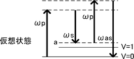
図1Aは、CARSにおいてアンチストークス光が生じるまでのエネルギー準位過程を示す説明図である。
図1Aに示すように、パルス発振させたポンプ光(角周波数ωp)と、パルス発振させたストークス光(角周波数ωs)とを、前記被験対象に時空間的に同時に照射する。このとき、前記ポンプ光と前記ストークス光との角周波数差(Δω=ωp−ωs)が被験対象の分子における振動バンドであると、前記分子のエネルギー準位は、前記ポンプ光により基底準位V=0から上準位へ上がるとともに、前記ストークス光により励起準位V=1に誘導される。その後、前記ポンプ光を前記被験対象に照射すると、より上準位へ上がった後、基底準位V=0に下がる過程でアンチストークス光を生じる。
前記ポンプ光における前記パルスの幅、及び、前記ストークス光における前記パルスの幅としては、特に制限はなく、目的に応じて適宜選択することができるが、ピコ秒間オーダーが好ましい。これにより、前記被験対象に対して非侵襲になるとともに、前記非共鳴信号に対する前記共鳴信号の比(以下、「共鳴信号/非共鳴信号比」と称することもある)が確保しやすい。FIG. 1A is an explanatory diagram showing an energy level process until anti-Stokes light is generated in CARS.
As shown in FIG. 1A, the pulse-oscillated pump light (angular frequency ω p ) and the pulse-oscillated Stokes light (angular frequency ω s ) are simultaneously irradiated to the test subject in spite and space. At this time, if the angular frequency difference (Δω = ω p −ω s ) between the pump light and the Stokes light is the vibration band in the molecule to be tested, the energy level of the molecule is based on the pump light. As the position V = 0 rises to the upper level, the Stokes light induces the excitation level V = 1. After that, when the test subject is irradiated with the pump light, anti-Stokes light is generated in the process of rising to the higher level and then lowering to the basal level V = 0.
The width of the pulse in the pump light and the width of the pulse in the Stokes light are not particularly limited and may be appropriately selected depending on the intended purpose, but are preferably on the order of picoseconds. As a result, the test subject becomes non-invasive, and the ratio of the resonance signal to the non-resonance signal (hereinafter, may be referred to as “resonance signal / non-resonance signal ratio”) can be easily secured.
図1Bは、ポンプ光、ストークス光、及びアンチストークス光の角周波数の関係を示す説明図である。
図1Bに示すように、前記ストークス光の角周波数ωs及び前記アンチストークス光の角周波数ωasは、エネルギー準位の関係から、前記ポンプ光の角周波数ωpを中心にそれぞれ±Δω離れて存在する。即ち、前記ストークス光の角周波数は、次式、ωs=ωp−Δωと表すことができる。また、前記アンチストークス光の角周波数は、次式、ωas=2ωp−ωs=ωp+Δωと表すことができる。FIG. 1B is an explanatory diagram showing the relationship between the angular frequencies of the pump light, the Stokes light, and the anti-Stokes light.
As shown in FIG. 1B, the angular frequency ω s of the Stokes light and the angular frequency ω as of the anti-Stokes light are separated by ± Δω about the angular frequency ω p of the pump light due to the energy level relationship. Exists. That is, the angular frequency of the Stokes light can be expressed by the following equation, ω s = ω p − Δω. Further, the angular frequency of the anti-Stokes light can be expressed by the following equation, ω as = 2ω p −ω s = ω p + Δω.
図2Aは、分子振動の励起準位V=1を経たときに共鳴アンチストークス光となる共鳴過程を示す説明図である。図2Bは、分子振動の励起準位V=1を経ないときに非共鳴アンチストークス光となる非共鳴過程を示す説明図である。
図2A及び図2Bに示すように、前記アンチストークス光には、前記共鳴アンチストークス光(以下、「共鳴信号」又は単に「アンチストークス光」と称することもある)及び前記非共鳴アンチストークス光(以下、「非共鳴信号」と称することもある)の2種類がある。
前記共鳴過程を経て生じた前記共鳴アンチストークス光は、前記被験対象が有する分子から生じたものであり、前記分子分布イメージ画像を生成する際に用いられる。
前記非共鳴過程を経て生じた前記非共鳴アンチストークス光は、前記波長差にほとんど依存せず、水の電子励起が関与した応答である。FIG. 2A is an explanatory diagram showing a resonance process that becomes resonance anti-Stokes light when the excitation level V = 1 of molecular vibration is passed. FIG. 2B is an explanatory diagram showing a non-resonant process that becomes non-resonant anti-Stokes light when the excitation level V = 1 of the molecular vibration is not passed.
As shown in FIGS. 2A and 2B, the anti-Stokes light includes the resonance anti-Stokes light (hereinafter, also referred to as “resonance signal” or simply “anti-Stokes light”) and the non-resonant anti-Stokes light (hereinafter, may be referred to as “anti-resonance signal”) Hereinafter, there are two types (sometimes referred to as "non-resonant signal").
The resonance anti-Stokes light generated through the resonance process is generated from a molecule possessed by the test subject, and is used when generating the molecular distribution image.
The non-resonant anti-Stokes light generated through the non-resonant process is a response involving electronic excitation of water, which is almost independent of the wavelength difference.
<断層画像生成部>
前記断層画像生成部は、前記ポンプ光を照射したときの前記被験対象からの反射光、及び、前記ストークス光を照射したときの前記被験対象からの反射光の少なくともいずれかを検出し、検出した前記反射光に基づいて前記被験対象の断層画像を生成する。
前記断層画像は、例えば、OCT(Optical Coherence Tomography)などにより取得することができるが、SS−OCT(Swept Source Optical Coherence Tomography)が好ましい。
前記断層画像生成部は、前記ポンプ光を照射したときの前記被験対象からの前記反射光、及び、前記ストークス光を照射したときの前記被験対象からの前記反射光の少なくともいずれかを干渉光とし、前記干渉光を分光したスペクトル干渉信号に対してフーリエ逆変換の演算処理を行うことが好ましい。<Tomographic image generator>
The tomographic image generation unit has detected and detected at least one of the reflected light from the test subject when the pump light is irradiated and the reflected light from the test subject when the Stokes light is irradiated. A tomographic image of the test subject is generated based on the reflected light.
The tomographic image can be obtained by, for example, OCT (Optical Coherence Tomography), but SS-OCT (Swept Source Optical Coherence Tomography) is preferable.
The tomographic image generation unit uses at least one of the reflected light from the test subject when irradiated with the pump light and the reflected light from the test subject when irradiated with the Stokes light as interference light. , It is preferable to perform arithmetic processing of inverse Fourier conversion on the spectral interference signal obtained by dispersing the interference light.
<画像表示部>
前記画像表示部は、生成された前記分子分布イメージ画像及び前記断層画像の少なくともいずれかを表示する。
前記画像表示部としては、特に制限はなく、目的に応じて適宜選択することができ、例えば、液晶モニターなどが挙げられる。<Image display>
The image display unit displays at least one of the generated molecular distribution image image and the tomographic image.
The image display unit is not particularly limited and may be appropriately selected depending on the intended purpose. Examples thereof include a liquid crystal monitor.
<その他の部>
前記その他の部としては、特に制限はなく、目的に応じて適宜選択することができるが、信号処理部を有することが好ましい。
前記信号処理部としては、特に制限はなく、目的に応じて適宜選択することができるが、前記ポンプ光を照射したときの前記被験対象からの前記反射光に基づくデータと、前記ストークス光を照射したときの前記被験対象からの前記反射光に基づくデータとを、前記波長差が0となる波長において結合させることが好ましい。<Other departments>
The other unit is not particularly limited and may be appropriately selected depending on the intended purpose, but it is preferable to have a signal processing unit.
The signal processing unit is not particularly limited and may be appropriately selected depending on the intended purpose. However, the data based on the reflected light from the test subject when the pump light is irradiated and the Stokes light are irradiated. It is preferable to combine the data based on the reflected light from the test object at that time at a wavelength at which the wavelength difference becomes 0.
図3は、グルコース溶液に前記ポンプ光及び前記ストークス光を同時に照射したときの、前記アンチストークス光の信号強度におけるストークス光の波長に対する依存性を示すグラフであり、縦軸が前記アンチストークス光の信号強度(mV)、横軸が前記ストークス光の波長(nm)である。図3では、前記ポンプ光の波長を1,064nmに固定し、前記ストークス光の波長を変化させ、前記グルコース溶液からの前記アンチストークス光の信号強度をプロットしたものである。
図3に示すように、前記ストークス光の波長において1,209nmを中心とした±6nmの範囲では、前記アンチストークス光の信号強度が低下していないことが確認できる。このことから、前記ストークス光の波長を掃引しながら前記アンチストークス光を10nm程度の範囲で前記スペクトル干渉信号として検出することにより、前記アンチストークス光の光軸方向における分解能を確保することができる。また、前記ストークス光の波長を掃引しながら前記ストークス光の反射光を前記スペクトル干渉信号として検出することにより、SS−OCT(Swept Source Optical Coherence Tomography)における深度方向のスペクトル干渉信号(以下、「Aライン信号」と称することもある)の取得を行ったこととなり、前記断層画像を生成することができる。FIG. 3 is a graph showing the dependence of the anti-Stokes light on the wavelength of the Stokes light when the glucose solution is simultaneously irradiated with the pump light and the Stokes light, and the vertical axis represents the anti-Stokes light. The signal strength (mV) and the horizontal axis are the wavelengths (nm) of the Stokes light. In FIG. 3, the wavelength of the pump light is fixed at 1,064 nm, the wavelength of the Stokes light is changed, and the signal intensity of the anti-Stokes light from the glucose solution is plotted.
As shown in FIG. 3, it can be confirmed that the signal intensity of the anti-Stokes light does not decrease in the range of ± 6 nm centered on 1,209 nm in the wavelength of the Stokes light. From this, it is possible to secure the resolution of the anti-Stokes light in the optical axis direction by detecting the anti-Stokes light as the spectral interference signal in a range of about 10 nm while sweeping the wavelength of the Stokes light. Further, by detecting the reflected light of the Stokes light as the spectral interference signal while sweeping the wavelength of the Stokes light, the spectral interference signal in the depth direction in SS-OCT (Swept Source Optical Coherence Tomography) (hereinafter, "A"). (Sometimes referred to as a line signal) has been acquired, and the tomographic image can be generated.
以下、本発明の実施例を説明するが、本発明は、これらの実施例に何ら限定されるものではない。 Examples of the present invention will be described below, but the present invention is not limited to these examples.
図4は、実施例における被験対象可視化装置を示す説明図である。
図4に示すように、被験対象可視化装置10は、光照射部100と、分子分布イメージ画像生成部200と、断層画像生成部300と、信号処理部400と、画像表示部500と、を有する。
光照射部100の基本波レーザー101は、波長が1,064nmのレーザービームをダイクロイックミラー102に出射する。前記レーザービームは、ピコ秒あるいはフェムト秒のモードを同期させたモードロックレーザービームである。FIG. 4 is an explanatory diagram showing a test object visualization device in the example.
As shown in FIG. 4, the test object visualization device 10 includes a
The
ダイクロイックミラー102は、S1面において、波長が1,064nmの光に対して非反射特性を有する。また、ダイクロイックミラー102は、S2面において、波長が1,064nmの光に対して非反射特性を有し、かつ波長が532nmの光に対して全反射特性を有する。
The
ダイクロイックミラー105は、S3面において、波長が532nmの光に対して非反射特性を有する。また、ダイクロイックミラー105は、S4面において、波長が900nm〜1,200nmの光に対して全反射特性を有し、かつ波長が532nmの光に対して非反射特性を有する。
The
全反射ミラー109は、S5面において、波長が900nm〜1,200nmの光に対して全反射特性を有する。
The
出力ミラー111は、S6面において、波長が900nm〜1,200nmの光に対して70%PR(Partial Reflection)特性を有し、かつ波長が532nmの光に対して全反射特性を有する。また、出力ミラー111は、S7面において、波長が900nm〜1,200nmの光に対して非反射特性を有する。 The output mirror 111 has a 70% PR (Partial Reflection) characteristic for light having a wavelength of 900 nm to 1,200 nm and a total reflection characteristic for light having a wavelength of 532 nm on the S6 surface. Further, the output mirror 111 has a non-reflective characteristic with respect to light having a wavelength of 900 nm to 1,200 nm on the S7 surface.
ダイクロイックミラー102と全反射ミラー109との間の空間は、波長が532nmの光を閉じ込める光閉じ込め器(Cavity)を形成している。
なお、ダイクロイックミラー102が移動ステージ103に設けられていることにより、前記光閉じ込め器の光路長を制御することができる。The space between the
Since the
全反射ミラー109、ダイクロイックミラー105及び出力ミラー111によるL型の空間は、光共振器(Optical Parametric Oscillation Cavity)を形成している。
前記光共振器では、波長が532nmの光が光パラメトリック結晶106を同一光路で通過する毎に前記シグナル光及び前記アイドラ光が増幅し、出力ミラー111の閾値を超えた前記シグナル光及び前記アイドラ光が、前記ポンプ光(図4中、点線矢印で示す)及び前記ストークス光(図4中、破線矢印で示す)として出力ミラー111から出射される。
なお、前記光閉じ込め器と前記光共振器とが光パラメトリック結晶106を共有している。また、全反射ミラー109が移動ステージ110に設けられていることにより、前記光共振器の光路長を制御することができる。また、同一光路で発生させた前記ポンプ光の波長及び前記ストークス光の波長は、ガルバノ電源108からガルバノ駆動信号を入力されたガルバノモーター107を用いて、光パラメトリック結晶106の角度を変化させることにより、それぞれ可変させることができる。The L-shaped space formed by the
In the optical resonator, the signal light and the idler light are amplified each time light having a wavelength of 532 nm passes through the optical
The optical confinement device and the optical resonator share an optical
移動ステージ103及び110により、波長が532nmの光が前記光閉じ込め器を往復する時間と、前記光共振器を往復する時間とを一致させ、前記光の1パルス周期内で光パラメトリック結晶106を複数回通過させて励起させる。
The moving
前記光パラメトリック発振により、出力ミラー111から前記ポンプ光及び前記ストークス光が、直交した偏光方向で空間的にも時間的にも重なりあった状態で出射される。
直交偏光2周波の前記ポンプ光及び前記ストークス光は、光軸方向を直交軸に対し45°傾けた偏光子112を通過させることにより、45°方向に偏光方向が一致した前記ポンプ光及び前記ストークス光となる。Due to the optical parametric oscillation, the pump light and the Stokes light are emitted from the output mirror 111 in a state of overlapping spatially and temporally in orthogonal polarization directions.
The pump light and the Stokes light having two frequencies of orthogonally polarized light pass through a
次に、断層画像の取得動作について説明する。
45°方向に偏光方向が一致した前記ポンプ光と前記ストークス光は、それぞれハーフミラー113により分光される。Next, the operation of acquiring the tomographic image will be described.
The pump light and the Stokes light whose polarization directions coincide with each other in the 45 ° direction are separated by a half mirror 113, respectively.
ハーフミラー113により二分された一方の前記ポンプ光と前記ストークス光は、ガルバノミラー115及び116を介して前記被験対象としての眼球部20の眼底に入射して、眼球部20の屈折率境界部において反射し、前記ポンプ光の反射光及び前記ストークス光の反射光として再びハーフミラー113に入射する。
The pump light and the Stokes light, which are divided into two by the half mirror 113, enter the fundus of the
ハーフミラー113により二分された他方の前記ポンプ光と前記ストークス光は、反射ミラー301において反射し、干渉光を得るための参照光としてハーフミラー113上で、前記被験対象からの前記ポンプ光の反射光及び前記ストークス光の反射光と重なり合う。
重なり合った前記参照光と前記反射光は、波長が1,064nm以上の光を反射するロングパスダイクロイックミラー302により、前記ポンプ光の前記干渉光及び前記ストークス光の前記干渉光とに分離され、それぞれ光検出器303及び304に入射する。The other pump light and the Stokes light divided into two by the half mirror 113 are reflected by the
The overlapping reference light and reflected light are separated into the interference light of the pump light and the interference light of the Stokes light by a long-pass
図5は、ポンプ光及びストークス光の波長可変範囲、被験対象の分子における振動バンド、及びアンチストークス光の波長との関係の一例を示す説明図である。
図5に示すように、前記波長差を可変させる範囲における最小値δmin及び最大値δmaxは、複数の被験対象の分子における振動バンドをδnとすると、次式、0=δmin<δn<δmaxとする。
例えば、被験対象の分子における振動バンドとして、512cm−1のグルコースの骨格振動バンドδ1、1,050cm−1のルチノールのC−O振動バンドδ2、及び1,159cm−1のルテインのC−C振動バンドδ3とする。この場合、前記波長差を可変させる範囲は、0cm−1<δ<1,400cm−1とする。また、前記ポンプ光の波長は、990nm≦λpump≦1,064nmの範囲を、前記ストークス光の波長は、1,150nm≧λstokes≧1,064nmの範囲を変化させる。
これにより、前記ストークス光を検出する光検出器303は、1,064nm≦λstokes≦1,150nmのスペクトル干渉信号を出力し、前記ポンプ光を検出する光検出器304は、1,064nm≧λpump≧990nmのスペクトル干渉信号を出力する。FIG. 5 is an explanatory diagram showing an example of the relationship between the wavelength tunable range of pump light and Stokes light, the vibration band in the molecule to be tested, and the wavelength of anti-Stokes light.
As shown in FIG. 5, the minimum value δ min and the maximum value δ max in the range in which the wavelength difference is variable are defined by the following equation, 0 = δ min <δ, where δ n is the vibration band in the molecules of a plurality of test subjects. Let n <δ max .
For example, as a vibration band in the molecules of the subject, skeletal vibration band [delta] 1 of glucose 512cm -1, C-O vibrational bands [delta] 2 of Ruchinoru of 1,050Cm -1, and 1,159cm -1 lutein C- Let the C vibration band δ 3 be used. In this case, the range for varying the wavelength difference, a 0cm -1 <δ <1,400cm -1. The wavelength of the pump light changes in the range of 990 nm ≤ λ pump ≤ 1,064 nm, and the wavelength of the Stokes light changes in the range of 1,150 nm ≧ λ stokes ≧ 1,064 nm.
As a result, the
それぞれの前記スペクトル干渉信号は、信号処理部400により、前記波長差が0となる波長1,064nmにおいて結合され、990nm≦λ≦1,150nmのスペクトル干渉信号となる。前記スペクトル干渉信号をフーリエ逆変換すると、深度分解能が、次式、Δz=(2ln2)/π・(λ0 2/Δλ)=3.16μmである、前記断層画像を生成するための前記Aライン信号となる。前記Aライン信号の計測をX方向に走査することにより、前記断層画像を得ることができる。なお、lnは、自然対数であり、λ0は、前記アンチストークス光の波長であり、Δλは、前記ポンプ光及び前記ストークス光の波長を掃引する際の前記ステップである。Each of the spectral interference signals is combined by the
次に、分子分布イメージ画像の取得動作について図4を参照して説明する。
ハーフミラー113により分光された一方の前記ポンプ光及び前記ストークス光は、更にハーフミラー201により分光される。Next, the operation of acquiring the molecular distribution image will be described with reference to FIG.
The pump light and the Stokes light dispersed by the half mirror 113 are further separated by the
ハーフミラー201により分光された一方の前記ポンプ光及び前記ストークス光は、前記非共鳴アンチストークス光の参照光を発生させるために、アンチストークス光発生用試料としての水202及び反射ミラー203を介してレンズ213で集束される。集束点で誘起された前記非共鳴アンチストークス光は、反射ミラー203により反射し、レンズ213で集光されて平行光として再びハーフミラー201に入射する。
One of the pump lights and the Stokes light spectroscopically separated by the
ハーフミラー201により二分された他方の前記ポンプ光及び前記ストークス光は、ガルバノミラー115及び116を介して、前記被験対象としての眼球部20に入射し、眼球部20の水晶体で集束され眼底網膜に達する。前記ポンプ光及び前記ストークス光を照射された前記眼底網膜内に存在する被験対象の分子から、前記共鳴アンチストークス光が生じる。生じた前記共鳴アンチストークス光は、前記水晶体で集光され、平行光としてハーフミラー201上において、干渉光を得るための参照光としての前記非共鳴アンチストークス光と重なり合う。
The other pump light and the Stokes light divided into two by the
波長が990nm以上の光を反射するロングパスダイクロイックミラー204は、重なり合った前記共鳴アンチストークス光及び前記非共鳴アンチストークス光と、同一の光軸方向である前記ポンプ光及び前記ストークス光とを分離する。
分離された前記共鳴アンチストークス光と前記非共鳴アンチストークス光は、波長が950nm以上の光を反射するロングパスダイクロイックミラー205により分離され、グルコース骨格の振動モードにおけるアンチストークス光(984nm光)がグルコース共鳴信号として光検出器206に入射する。
ロングパスダイクロイックミラー205が反射したルチノールC−O振動モードのアンチストークス光(911nm光)とルテインC−C振動モードのアンチストークス光(898nm光)は、波長が905nm以上の光を反射するロングパスダイクロイックミラー208により分離され、それぞれルチノール共鳴信号、ルテイン共鳴信号として光検出器209及び211に入射する。The long-pass
The separated resonance anti-Stokes light and the non-resonant anti-Stokes light are separated by a long-pass
The anti-Stokes light (911 nm light) in the rutinol CO vibration mode and the anti-Stokes light (898 nm light) in the lutein CC vibration mode reflected by the long-pass
図5に示すように、波長差δの可変範囲0cm−1<δ<1,400cm−1においては、グルコース骨格振動の512cm−1に対応した前記共鳴アンチストークス光(波長984nm)が、ルチノールのC−O振動の1,050cm−1に対応した前記共鳴アンチストークス光(波長911nm)が、ルテインのC−C振動の1,525cm−1に対応した前記共鳴アンチストークス光(波長898nm)が、それぞれの中心波長から±5nm程度の範囲で生じる。
これらの前記共鳴アンチストークス光は、前記参照光としての前記非共鳴アンチストークス光とハーフミラー201上で重ね合わされ、光検出器206、209、及び211で検出される。As shown in FIG. 5, in the variable range 0cm -1 <δ <1,400cm -1 in wavelength difference [delta], the resonance anti-Stokes light corresponding to 512cm -1 glucose skeleton vibration (wavelength 984 nm) is the Ruchinoru the resonance anti-Stokes light corresponding to 1,050Cm -1 of C-O vibrations (wavelength 911nm) is, the resonance anti-Stokes light corresponding to 1,525Cm -1 of C-C vibration of lutein (wavelength 898nm) is, It occurs in the range of about ± 5 nm from each center wavelength.
These resonance anti-Stokes lights are superposed on the
光検出器206、209、及び211からの出力は、ハイパスフィルター207、210、及び212により直流成分が除かれ、スペクトル干渉信号となる。
前記スペクトル干渉信号をフーリエ逆変換すると、深度分解能が、次式、Δz=(2ln2)/π・(λ0 2/Δλ)=(2ln2)/π・(0.92/0.01)=35μmである、前記分子分布イメージ画像を生成するための前記Aライン信号となる。前記Aライン信号の計測をX方向に走査することにより、前記分子分布イメージ画像を得ることができる。
従来の前記CARSを用いた前記分子分布イメージング技術では、高開口数とした光学系を用いて光軸方向への走査が必要であったが、前記アンチストークス光(CARS光)のスペクトル干渉信号をフーリエ逆変換することにより、光軸方向へ走査するための機構を不要にすることができる。The outputs from the
When inverse Fourier transform of the spectral interference signal, the depth resolution, the following equation, Δz = (2ln2) / π · (
In the conventional molecular distribution imaging technique using the CARS, scanning in the optical axis direction is required using an optical system having a high numerical aperture, but the spectral interference signal of the anti-Stokes light (CARS light) is used. By performing the inverse Fourier transform, it is possible to eliminate the need for a mechanism for scanning in the optical axis direction.
以上のような動作により、前記被験対象における前記分子分布イメージ画像及び前記断層画像を同時に取得することができる。
なお、X方向のみならずY方向に光走査を行うことにより、前記被験対象における分子分布イメージの3次元画像、及び形態の3次元画像を同時に取得することができる。By the above operation, the molecular distribution image image and the tomographic image of the test subject can be acquired at the same time.
By performing optical scanning not only in the X direction but also in the Y direction, a three-dimensional image of the molecular distribution image in the test object and a three-dimensional image of the morphology can be simultaneously acquired.
10 被験対象可視化装置
20 眼球部(被験対象)
100 光照射部
200 分子分布イメージ画像生成部
300 断層画像生成部
400 信号処理部
500 画像表示部10
100
Claims (7)
前記ポンプ光及び前記ストークス光の波長差に応じて前記被験対象から生じるアンチストークス光を検出し、前記アンチストークス光に基づいて分子分布イメージ画像を生成する分子分布イメージ画像生成部と、
前記ポンプ光を照射したときの前記被験対象からの反射光、及び、前記ストークス光を照射したときの前記被験対象からの反射光の少なくともいずれかを検出し、検出した前記反射光に基づいて前記被験対象の断層画像を生成する断層画像生成部と、
生成された前記分子分布イメージ画像及び前記断層画像の少なくともいずれかを表示する画像表示部とを有することを特徴とする被験対象可視化装置。A light irradiation unit that irradiates the test subject with the pump light and the Stokes light by varying at least one of the wavelengths of the pump light and the Stokes light generated on the same optical axis for each inspection site of the test target.
A molecular distribution image image generation unit that detects anti-Stokes light generated from the test subject according to the wavelength difference between the pump light and the Stokes light and generates a molecular distribution image based on the anti-Stokes light.
At least one of the reflected light from the test subject when irradiated with the pump light and the reflected light from the test subject when irradiated with the Stokes light is detected, and the reflected light is based on the detected light. A tomographic image generator that generates a tomographic image of the test subject,
A test object visualization device including an image display unit that displays at least one of the generated molecular distribution image image and the tomographic image.
前記断層画像生成部が、前記ポンプ光を照射したときの前記被験対象からの前記反射光に基づくデータと、前記ストークス光を照射したときの前記被験対象からの前記反射光に基づくデータとを、前記波長差が0となる波長において結合させたデータに基づいて前記断層画像を生成する請求項1に記載の被験対象可視化装置。The pump light and the Stokes light are used so that the wavelength difference between the pump light and the Stokes light becomes 0 in a range in which the light irradiation unit changes the wavelength of the pump light and the wavelength of the Stokes light. Irradiate the subject and
When the tomographic image generation unit irradiates the pump light, the data based on the reflected light from the test subject and the data based on the reflected light from the test subject when the Stokes light is irradiated are obtained. The test object visualization device according to claim 1, wherein the tomographic image is generated based on the combined data at a wavelength at which the wavelength difference becomes 0.
光の入射角度に応じて前記光の波長を変換する光パラメトリック結晶を有し、前記光を閉じ込める光閉じ込め器と、
前記光パラメトリック結晶を前記光閉じ込め器と共有し、前記光パラメトリック結晶により波長が変換された光を増幅させる光共振器とを備える請求項1から4のいずれかに記載の被験対象可視化装置。The light irradiation unit
An optical parametric crystal that has an optical parametric crystal that converts the wavelength of the light according to the incident angle of the light, and an optical confinement device that traps the light.
The subject visualization apparatus according to any one of claims 1 to 4, further comprising an optical resonator that shares the optical parametric crystal with the optical confinement device and amplifies light whose wavelength is converted by the optical parametric crystal.
Applications Claiming Priority (3)
| Application Number | Priority Date | Filing Date | Title |
|---|---|---|---|
| JP2016121108 | 2016-06-17 | ||
| JP2016121108 | 2016-06-17 | ||
| PCT/JP2017/022295 WO2017217534A1 (en) | 2016-06-17 | 2017-06-16 | Test object visualizing device |
Publications (2)
| Publication Number | Publication Date |
|---|---|
| JPWO2017217534A1 JPWO2017217534A1 (en) | 2019-04-04 |
| JP6804773B2 true JP6804773B2 (en) | 2020-12-23 |
Family
ID=60663267
Family Applications (1)
| Application Number | Title | Priority Date | Filing Date |
|---|---|---|---|
| JP2018524032A Active JP6804773B2 (en) | 2016-06-17 | 2017-06-16 | Subject visualization device |
Country Status (4)
| Country | Link |
|---|---|
| US (1) | US10809200B2 (en) |
| EP (1) | EP3474001B1 (en) |
| JP (1) | JP6804773B2 (en) |
| WO (1) | WO2017217534A1 (en) |
Families Citing this family (3)
| Publication number | Priority date | Publication date | Assignee | Title |
|---|---|---|---|---|
| JP6754492B2 (en) * | 2018-01-18 | 2020-09-09 | 小出 珠貴 | Biological tissue analyzer and biological tissue analysis method |
| US11944407B2 (en) * | 2019-04-29 | 2024-04-02 | Atonarp Inc. | Hybrid optical system |
| US20220202292A1 (en) * | 2019-04-30 | 2022-06-30 | Atonarp Inc. | Measuring system |
Family Cites Families (10)
| Publication number | Priority date | Publication date | Assignee | Title |
|---|---|---|---|---|
| JPH09145619A (en) * | 1995-09-20 | 1997-06-06 | Kdk Corp | Method and instrument for spectroscopic measurement of scattered light and so on |
| EP0764844B1 (en) | 1995-09-20 | 2007-03-14 | ARKRAY, Inc | Method for analysis by light scattering |
| US20080117416A1 (en) * | 2006-10-27 | 2008-05-22 | Hunter Ian W | Use of coherent raman techniques for medical diagnostic and therapeutic purposes, and calibration techniques for same |
| GB0813980D0 (en) * | 2008-07-31 | 2008-09-10 | Univ St Andrews | Control of relaxation oscillations in intracavity optical parametric oscillato rs |
| ITMI20081448A1 (en) * | 2008-08-01 | 2010-02-02 | Milano Politecnico | SYSTEM OF GENERATION OF RAMAN SIGNAL ANALYSIS |
| FR2955664B1 (en) * | 2010-01-22 | 2012-02-10 | Centre Nat Rech Scient | METHOD FOR THE DETECTION OF A RESONANT NONLINEAR OPTICAL SIGNAL AND DEVICE FOR THE IMPLEMENTATION OF SAID METHOD |
| JP5510712B2 (en) * | 2010-02-22 | 2014-06-04 | 株式会社ニコン | Nonlinear microscope |
| WO2013047698A1 (en) * | 2011-09-30 | 2013-04-04 | 学校法人東京理科大学 | Optical interferometer, information acquisition apparatus, and information acquisition method |
| JP5901346B2 (en) * | 2012-02-27 | 2016-04-06 | 学校法人 埼玉医科大学 | Measuring device and measuring method |
| JP6255257B2 (en) * | 2014-01-28 | 2017-12-27 | 学校法人 埼玉医科大学 | Measuring device and measuring method |
-
2017
- 2017-06-16 US US16/309,732 patent/US10809200B2/en active Active
- 2017-06-16 WO PCT/JP2017/022295 patent/WO2017217534A1/en active Search and Examination
- 2017-06-16 JP JP2018524032A patent/JP6804773B2/en active Active
- 2017-06-16 EP EP17813428.4A patent/EP3474001B1/en active Active
Also Published As
| Publication number | Publication date |
|---|---|
| EP3474001A4 (en) | 2020-01-15 |
| US10809200B2 (en) | 2020-10-20 |
| US20190137402A1 (en) | 2019-05-09 |
| WO2017217534A1 (en) | 2017-12-21 |
| JPWO2017217534A1 (en) | 2019-04-04 |
| EP3474001B1 (en) | 2021-11-17 |
| EP3474001A1 (en) | 2019-04-24 |
Similar Documents
| Publication | Publication Date | Title |
|---|---|---|
| US7586618B2 (en) | Distinguishing non-resonant four-wave-mixing noise in coherent stokes and anti-stokes Raman scattering | |
| US10351616B2 (en) | Methods, arrangements and systems for obtaining information associated with an anatomical sample using optical microscopy | |
| US7623908B2 (en) | Nonlinear interferometric vibrational imaging | |
| US7075658B2 (en) | Method for optical coherence tomography imaging with molecular contrast | |
| Drexler et al. | Optical coherence tomography today: speed, contrast, and multimodality | |
| Meyer et al. | Expanding multimodal microscopy by high spectral resolution coherent anti-Stokes Raman scattering imaging for clinical disease diagnostics | |
| Vogler et al. | Multimodal imaging spectroscopy of tissue | |
| JP5901346B2 (en) | Measuring device and measuring method | |
| JP5679686B2 (en) | Optical coherence tomography system | |
| JP6804773B2 (en) | Subject visualization device | |
| WO2013047698A1 (en) | Optical interferometer, information acquisition apparatus, and information acquisition method | |
| JP6512756B2 (en) | Light source device and information acquisition device using the same | |
| US10433731B2 (en) | Continuous diode laser stimulated Raman gain/loss vibrational microscope | |
| JP2013127451A (en) | Analyzing device for analyzing state of dna | |
| Matthäus et al. | Multimodal nonlinear imaging of atherosclerotic plaques differentiation of triglyceride and cholesterol deposits | |
| JP6422449B2 (en) | Measuring device and measuring method | |
| Audier et al. | Shot noise limited high speed stimulated Raman microscopy | |
| Banno et al. | Stimulated Raman photoacoustic spectroscopy for chemical-contrast imaging of a sample deeply buried in scattering media | |
| JP2010175271A (en) | Optical tomographic image display system | |
| WO2013088746A1 (en) | Laser scanning method for measuring in vivo amount of specific substance | |
| Breunig et al. | Combining multiphoton and CARS microscopy for skin imaging | |
| Applegate et al. | Molecular contrast OCT | |
| Carrasco-Zevallos et al. | Pump-probe optical coherence tomography imaging of Zenopus tadpole vasculature ex vivo | |
| Haji Reza | All-Optical and Endoscopic Photoacoustic Microscopy | |
| Jacob | Design and Optimize a Two Color Fourier Domain Pump Probe Optical Coherence Tomography System |
Legal Events
| Date | Code | Title | Description |
|---|---|---|---|
| RD04 | Notification of resignation of power of attorney |
Free format text: JAPANESE INTERMEDIATE CODE: A7424 Effective date: 20190220 |
|
| A621 | Written request for application examination |
Free format text: JAPANESE INTERMEDIATE CODE: A621 Effective date: 20200313 |
|
| TRDD | Decision of grant or rejection written | ||
| A01 | Written decision to grant a patent or to grant a registration (utility model) |
Free format text: JAPANESE INTERMEDIATE CODE: A01 Effective date: 20201110 |
|
| A61 | First payment of annual fees (during grant procedure) |
Free format text: JAPANESE INTERMEDIATE CODE: A61 Effective date: 20201126 |
|
| R150 | Certificate of patent or registration of utility model |
Ref document number: 6804773 Country of ref document: JP Free format text: JAPANESE INTERMEDIATE CODE: R150 |
|
| R250 | Receipt of annual fees |
Free format text: JAPANESE INTERMEDIATE CODE: R250 |