JP6802075B2 - Honeycomb structure - Google Patents
Honeycomb structure Download PDFInfo
- Publication number
- JP6802075B2 JP6802075B2 JP2017008903A JP2017008903A JP6802075B2 JP 6802075 B2 JP6802075 B2 JP 6802075B2 JP 2017008903 A JP2017008903 A JP 2017008903A JP 2017008903 A JP2017008903 A JP 2017008903A JP 6802075 B2 JP6802075 B2 JP 6802075B2
- Authority
- JP
- Japan
- Prior art keywords
- honeycomb
- segment
- honeycomb structure
- segments
- bonding layer
- Prior art date
- Legal status (The legal status is an assumption and is not a legal conclusion. Google has not performed a legal analysis and makes no representation as to the accuracy of the status listed.)
- Active
Links
- 230000002093 peripheral effect Effects 0.000 claims description 38
- 238000007789 sealing Methods 0.000 claims description 22
- 238000005192 partition Methods 0.000 claims description 20
- 238000005304 joining Methods 0.000 claims description 12
- 239000012530 fluid Substances 0.000 claims description 8
- 239000010410 layer Substances 0.000 description 170
- 230000000052 comparative effect Effects 0.000 description 41
- 238000011156 evaluation Methods 0.000 description 30
- 239000007789 gas Substances 0.000 description 24
- 239000000463 material Substances 0.000 description 22
- 230000035939 shock Effects 0.000 description 14
- 238000000034 method Methods 0.000 description 11
- MWUXSHHQAYIFBG-UHFFFAOYSA-N nitrogen oxide Inorganic materials O=[N] MWUXSHHQAYIFBG-UHFFFAOYSA-N 0.000 description 9
- 230000007423 decrease Effects 0.000 description 8
- 230000008646 thermal stress Effects 0.000 description 8
- 238000005259 measurement Methods 0.000 description 7
- 238000010586 diagram Methods 0.000 description 6
- 238000010304 firing Methods 0.000 description 6
- 238000004519 manufacturing process Methods 0.000 description 6
- 229910052751 metal Inorganic materials 0.000 description 6
- 239000002184 metal Substances 0.000 description 6
- 125000006850 spacer group Chemical group 0.000 description 6
- 230000035882 stress Effects 0.000 description 6
- 239000000919 ceramic Substances 0.000 description 5
- 239000004927 clay Substances 0.000 description 5
- 239000000567 combustion gas Substances 0.000 description 5
- 238000006073 displacement reaction Methods 0.000 description 5
- 239000013618 particulate matter Substances 0.000 description 5
- HBMJWWWQQXIZIP-UHFFFAOYSA-N silicon carbide Chemical compound [Si+]#[C-] HBMJWWWQQXIZIP-UHFFFAOYSA-N 0.000 description 5
- 239000004071 soot Substances 0.000 description 5
- 229910000505 Al2TiO5 Inorganic materials 0.000 description 4
- ATUOYWHBWRKTHZ-UHFFFAOYSA-N Propane Chemical compound CCC ATUOYWHBWRKTHZ-UHFFFAOYSA-N 0.000 description 4
- 239000003054 catalyst Substances 0.000 description 4
- 239000011248 coating agent Substances 0.000 description 4
- 238000000576 coating method Methods 0.000 description 4
- 239000000446 fuel Substances 0.000 description 4
- AABBHSMFGKYLKE-SNAWJCMRSA-N propan-2-yl (e)-but-2-enoate Chemical compound C\C=C\C(=O)OC(C)C AABBHSMFGKYLKE-SNAWJCMRSA-N 0.000 description 4
- 238000000746 purification Methods 0.000 description 4
- 238000010008 shearing Methods 0.000 description 4
- 229910010271 silicon carbide Inorganic materials 0.000 description 4
- 238000012360 testing method Methods 0.000 description 4
- 238000001816 cooling Methods 0.000 description 3
- 238000005516 engineering process Methods 0.000 description 3
- QSHDDOUJBYECFT-UHFFFAOYSA-N mercury Chemical compound [Hg] QSHDDOUJBYECFT-UHFFFAOYSA-N 0.000 description 3
- 229910052753 mercury Inorganic materials 0.000 description 3
- 239000002994 raw material Substances 0.000 description 3
- 239000002002 slurry Substances 0.000 description 3
- 229910052581 Si3N4 Inorganic materials 0.000 description 2
- PNEYBMLMFCGWSK-UHFFFAOYSA-N aluminium oxide Inorganic materials [O-2].[O-2].[O-2].[Al+3].[Al+3] PNEYBMLMFCGWSK-UHFFFAOYSA-N 0.000 description 2
- 239000012298 atmosphere Substances 0.000 description 2
- 239000011230 binding agent Substances 0.000 description 2
- 239000011247 coating layer Substances 0.000 description 2
- 238000002485 combustion reaction Methods 0.000 description 2
- 229910052878 cordierite Inorganic materials 0.000 description 2
- 230000006866 deterioration Effects 0.000 description 2
- JSKIRARMQDRGJZ-UHFFFAOYSA-N dimagnesium dioxido-bis[(1-oxido-3-oxo-2,4,6,8,9-pentaoxa-1,3-disila-5,7-dialuminabicyclo[3.3.1]nonan-7-yl)oxy]silane Chemical compound [Mg++].[Mg++].[O-][Si]([O-])(O[Al]1O[Al]2O[Si](=O)O[Si]([O-])(O1)O2)O[Al]1O[Al]2O[Si](=O)O[Si]([O-])(O1)O2 JSKIRARMQDRGJZ-UHFFFAOYSA-N 0.000 description 2
- KZHJGOXRZJKJNY-UHFFFAOYSA-N dioxosilane;oxo(oxoalumanyloxy)alumane Chemical compound O=[Si]=O.O=[Si]=O.O=[Al]O[Al]=O.O=[Al]O[Al]=O.O=[Al]O[Al]=O KZHJGOXRZJKJNY-UHFFFAOYSA-N 0.000 description 2
- 238000002347 injection Methods 0.000 description 2
- 239000007924 injection Substances 0.000 description 2
- 239000011812 mixed powder Substances 0.000 description 2
- 239000000203 mixture Substances 0.000 description 2
- 229910052863 mullite Inorganic materials 0.000 description 2
- 239000004033 plastic Substances 0.000 description 2
- 229920003023 plastic Polymers 0.000 description 2
- 239000001294 propane Substances 0.000 description 2
- HQVNEWCFYHHQES-UHFFFAOYSA-N silicon nitride Chemical compound N12[Si]34N5[Si]62N3[Si]51N64 HQVNEWCFYHHQES-UHFFFAOYSA-N 0.000 description 2
- 238000000638 solvent extraction Methods 0.000 description 2
- 238000010998 test method Methods 0.000 description 2
- 238000009423 ventilation Methods 0.000 description 2
- XLYOFNOQVPJJNP-UHFFFAOYSA-N water Substances O XLYOFNOQVPJJNP-UHFFFAOYSA-N 0.000 description 2
- 229910002060 Fe-Cr-Al alloy Inorganic materials 0.000 description 1
- 238000009825 accumulation Methods 0.000 description 1
- 239000000654 additive Substances 0.000 description 1
- 230000000996 additive effect Effects 0.000 description 1
- 239000012300 argon atmosphere Substances 0.000 description 1
- 230000033228 biological regulation Effects 0.000 description 1
- 238000009924 canning Methods 0.000 description 1
- 229910010293 ceramic material Inorganic materials 0.000 description 1
- 238000006243 chemical reaction Methods 0.000 description 1
- 230000000295 complement effect Effects 0.000 description 1
- 239000002131 composite material Substances 0.000 description 1
- 238000007796 conventional method Methods 0.000 description 1
- -1 corderite Chemical compound 0.000 description 1
- 238000005238 degreasing Methods 0.000 description 1
- 230000007613 environmental effect Effects 0.000 description 1
- 239000010419 fine particle Substances 0.000 description 1
- 238000000227 grinding Methods 0.000 description 1
- 230000020169 heat generation Effects 0.000 description 1
- 238000010438 heat treatment Methods 0.000 description 1
- 229910052575 non-oxide ceramic Inorganic materials 0.000 description 1
- 239000011225 non-oxide ceramic Substances 0.000 description 1
- 230000003287 optical effect Effects 0.000 description 1
- 229910052574 oxide ceramic Inorganic materials 0.000 description 1
- 239000011224 oxide ceramic Substances 0.000 description 1
- 239000000843 powder Substances 0.000 description 1
- 238000003825 pressing Methods 0.000 description 1
- 230000008929 regeneration Effects 0.000 description 1
- 238000011069 regeneration method Methods 0.000 description 1
- 239000000565 sealant Substances 0.000 description 1
- SBEQWOXEGHQIMW-UHFFFAOYSA-N silicon Chemical compound [Si].[Si] SBEQWOXEGHQIMW-UHFFFAOYSA-N 0.000 description 1
- 229910052710 silicon Inorganic materials 0.000 description 1
- 239000010703 silicon Substances 0.000 description 1
- 239000011863 silicon-based powder Substances 0.000 description 1
- 229910052596 spinel Inorganic materials 0.000 description 1
- 239000011029 spinel Substances 0.000 description 1
- 239000000126 substance Substances 0.000 description 1
- 239000002341 toxic gas Substances 0.000 description 1
Images


Classifications
-
- B—PERFORMING OPERATIONS; TRANSPORTING
- B01—PHYSICAL OR CHEMICAL PROCESSES OR APPARATUS IN GENERAL
- B01D—SEPARATION
- B01D46/00—Filters or filtering processes specially modified for separating dispersed particles from gases or vapours
- B01D46/24—Particle separators, e.g. dust precipitators, using rigid hollow filter bodies
- B01D46/2403—Particle separators, e.g. dust precipitators, using rigid hollow filter bodies characterised by the physical shape or structure of the filtering element
- B01D46/2418—Honeycomb filters
- B01D46/2451—Honeycomb filters characterized by the geometrical structure, shape, pattern or configuration or parameters related to the geometry of the structure
- B01D46/2455—Honeycomb filters characterized by the geometrical structure, shape, pattern or configuration or parameters related to the geometry of the structure of the whole honeycomb or segments
-
- B—PERFORMING OPERATIONS; TRANSPORTING
- B01—PHYSICAL OR CHEMICAL PROCESSES OR APPARATUS IN GENERAL
- B01D—SEPARATION
- B01D46/00—Filters or filtering processes specially modified for separating dispersed particles from gases or vapours
- B01D46/24—Particle separators, e.g. dust precipitators, using rigid hollow filter bodies
- B01D46/2403—Particle separators, e.g. dust precipitators, using rigid hollow filter bodies characterised by the physical shape or structure of the filtering element
- B01D46/2418—Honeycomb filters
- B01D46/2451—Honeycomb filters characterized by the geometrical structure, shape, pattern or configuration or parameters related to the geometry of the structure
- B01D46/2466—Honeycomb filters characterized by the geometrical structure, shape, pattern or configuration or parameters related to the geometry of the structure of the adhesive layers, i.e. joints between segments
-
- B—PERFORMING OPERATIONS; TRANSPORTING
- B01—PHYSICAL OR CHEMICAL PROCESSES OR APPARATUS IN GENERAL
- B01D—SEPARATION
- B01D46/00—Filters or filtering processes specially modified for separating dispersed particles from gases or vapours
- B01D46/24—Particle separators, e.g. dust precipitators, using rigid hollow filter bodies
- B01D46/2403—Particle separators, e.g. dust precipitators, using rigid hollow filter bodies characterised by the physical shape or structure of the filtering element
- B01D46/2418—Honeycomb filters
- B01D46/2451—Honeycomb filters characterized by the geometrical structure, shape, pattern or configuration or parameters related to the geometry of the structure
- B01D46/247—Honeycomb filters characterized by the geometrical structure, shape, pattern or configuration or parameters related to the geometry of the structure of the cells
-
- B—PERFORMING OPERATIONS; TRANSPORTING
- B01—PHYSICAL OR CHEMICAL PROCESSES OR APPARATUS IN GENERAL
- B01D—SEPARATION
- B01D46/00—Filters or filtering processes specially modified for separating dispersed particles from gases or vapours
- B01D46/24—Particle separators, e.g. dust precipitators, using rigid hollow filter bodies
- B01D46/2403—Particle separators, e.g. dust precipitators, using rigid hollow filter bodies characterised by the physical shape or structure of the filtering element
- B01D46/2418—Honeycomb filters
- B01D46/2451—Honeycomb filters characterized by the geometrical structure, shape, pattern or configuration or parameters related to the geometry of the structure
- B01D46/2476—Monolithic structures
-
- B—PERFORMING OPERATIONS; TRANSPORTING
- B01—PHYSICAL OR CHEMICAL PROCESSES OR APPARATUS IN GENERAL
- B01D—SEPARATION
- B01D46/00—Filters or filtering processes specially modified for separating dispersed particles from gases or vapours
- B01D46/24—Particle separators, e.g. dust precipitators, using rigid hollow filter bodies
- B01D46/2403—Particle separators, e.g. dust precipitators, using rigid hollow filter bodies characterised by the physical shape or structure of the filtering element
- B01D46/2418—Honeycomb filters
- B01D46/2451—Honeycomb filters characterized by the geometrical structure, shape, pattern or configuration or parameters related to the geometry of the structure
- B01D46/2478—Structures comprising honeycomb segments
-
- B—PERFORMING OPERATIONS; TRANSPORTING
- B01—PHYSICAL OR CHEMICAL PROCESSES OR APPARATUS IN GENERAL
- B01D—SEPARATION
- B01D46/00—Filters or filtering processes specially modified for separating dispersed particles from gases or vapours
- B01D46/24—Particle separators, e.g. dust precipitators, using rigid hollow filter bodies
- B01D46/2403—Particle separators, e.g. dust precipitators, using rigid hollow filter bodies characterised by the physical shape or structure of the filtering element
- B01D46/2418—Honeycomb filters
- B01D46/2451—Honeycomb filters characterized by the geometrical structure, shape, pattern or configuration or parameters related to the geometry of the structure
- B01D46/2482—Thickness, height, width, length or diameter
-
- B—PERFORMING OPERATIONS; TRANSPORTING
- B01—PHYSICAL OR CHEMICAL PROCESSES OR APPARATUS IN GENERAL
- B01D—SEPARATION
- B01D46/00—Filters or filtering processes specially modified for separating dispersed particles from gases or vapours
- B01D46/24—Particle separators, e.g. dust precipitators, using rigid hollow filter bodies
- B01D46/2403—Particle separators, e.g. dust precipitators, using rigid hollow filter bodies characterised by the physical shape or structure of the filtering element
- B01D46/2418—Honeycomb filters
- B01D46/2451—Honeycomb filters characterized by the geometrical structure, shape, pattern or configuration or parameters related to the geometry of the structure
- B01D46/2484—Cell density, area or aspect ratio
-
- B—PERFORMING OPERATIONS; TRANSPORTING
- B01—PHYSICAL OR CHEMICAL PROCESSES OR APPARATUS IN GENERAL
- B01D—SEPARATION
- B01D46/00—Filters or filtering processes specially modified for separating dispersed particles from gases or vapours
- B01D46/24—Particle separators, e.g. dust precipitators, using rigid hollow filter bodies
- B01D46/2403—Particle separators, e.g. dust precipitators, using rigid hollow filter bodies characterised by the physical shape or structure of the filtering element
- B01D46/2418—Honeycomb filters
- B01D46/2451—Honeycomb filters characterized by the geometrical structure, shape, pattern or configuration or parameters related to the geometry of the structure
- B01D46/2486—Honeycomb filters characterized by the geometrical structure, shape, pattern or configuration or parameters related to the geometry of the structure characterised by the shapes or configurations
-
- B—PERFORMING OPERATIONS; TRANSPORTING
- B01—PHYSICAL OR CHEMICAL PROCESSES OR APPARATUS IN GENERAL
- B01J—CHEMICAL OR PHYSICAL PROCESSES, e.g. CATALYSIS OR COLLOID CHEMISTRY; THEIR RELEVANT APPARATUS
- B01J35/00—Catalysts, in general, characterised by their form or physical properties
- B01J35/50—Catalysts, in general, characterised by their form or physical properties characterised by their shape or configuration
- B01J35/56—Foraminous structures having flow-through passages or channels, e.g. grids or three-dimensional monoliths
-
- C—CHEMISTRY; METALLURGY
- C04—CEMENTS; CONCRETE; ARTIFICIAL STONE; CERAMICS; REFRACTORIES
- C04B—LIME, MAGNESIA; SLAG; CEMENTS; COMPOSITIONS THEREOF, e.g. MORTARS, CONCRETE OR LIKE BUILDING MATERIALS; ARTIFICIAL STONE; CERAMICS; REFRACTORIES; TREATMENT OF NATURAL STONE
- C04B35/00—Shaped ceramic products characterised by their composition; Ceramics compositions; Processing powders of inorganic compounds preparatory to the manufacturing of ceramic products
- C04B35/01—Shaped ceramic products characterised by their composition; Ceramics compositions; Processing powders of inorganic compounds preparatory to the manufacturing of ceramic products based on oxide ceramics
- C04B35/46—Shaped ceramic products characterised by their composition; Ceramics compositions; Processing powders of inorganic compounds preparatory to the manufacturing of ceramic products based on oxide ceramics based on titanium oxides or titanates
- C04B35/462—Shaped ceramic products characterised by their composition; Ceramics compositions; Processing powders of inorganic compounds preparatory to the manufacturing of ceramic products based on oxide ceramics based on titanium oxides or titanates based on titanates
- C04B35/478—Shaped ceramic products characterised by their composition; Ceramics compositions; Processing powders of inorganic compounds preparatory to the manufacturing of ceramic products based on oxide ceramics based on titanium oxides or titanates based on titanates based on aluminium titanates
-
- C—CHEMISTRY; METALLURGY
- C04—CEMENTS; CONCRETE; ARTIFICIAL STONE; CERAMICS; REFRACTORIES
- C04B—LIME, MAGNESIA; SLAG; CEMENTS; COMPOSITIONS THEREOF, e.g. MORTARS, CONCRETE OR LIKE BUILDING MATERIALS; ARTIFICIAL STONE; CERAMICS; REFRACTORIES; TREATMENT OF NATURAL STONE
- C04B35/00—Shaped ceramic products characterised by their composition; Ceramics compositions; Processing powders of inorganic compounds preparatory to the manufacturing of ceramic products
- C04B35/515—Shaped ceramic products characterised by their composition; Ceramics compositions; Processing powders of inorganic compounds preparatory to the manufacturing of ceramic products based on non-oxide ceramics
- C04B35/56—Shaped ceramic products characterised by their composition; Ceramics compositions; Processing powders of inorganic compounds preparatory to the manufacturing of ceramic products based on non-oxide ceramics based on carbides or oxycarbides
- C04B35/565—Shaped ceramic products characterised by their composition; Ceramics compositions; Processing powders of inorganic compounds preparatory to the manufacturing of ceramic products based on non-oxide ceramics based on carbides or oxycarbides based on silicon carbide
-
- C—CHEMISTRY; METALLURGY
- C04—CEMENTS; CONCRETE; ARTIFICIAL STONE; CERAMICS; REFRACTORIES
- C04B—LIME, MAGNESIA; SLAG; CEMENTS; COMPOSITIONS THEREOF, e.g. MORTARS, CONCRETE OR LIKE BUILDING MATERIALS; ARTIFICIAL STONE; CERAMICS; REFRACTORIES; TREATMENT OF NATURAL STONE
- C04B35/00—Shaped ceramic products characterised by their composition; Ceramics compositions; Processing powders of inorganic compounds preparatory to the manufacturing of ceramic products
- C04B35/622—Forming processes; Processing powders of inorganic compounds preparatory to the manufacturing of ceramic products
- C04B35/626—Preparing or treating the powders individually or as batches ; preparing or treating macroscopic reinforcing agents for ceramic products, e.g. fibres; mechanical aspects section B
- C04B35/63—Preparing or treating the powders individually or as batches ; preparing or treating macroscopic reinforcing agents for ceramic products, e.g. fibres; mechanical aspects section B using additives specially adapted for forming the products, e.g.. binder binders
- C04B35/632—Organic additives
-
- C—CHEMISTRY; METALLURGY
- C04—CEMENTS; CONCRETE; ARTIFICIAL STONE; CERAMICS; REFRACTORIES
- C04B—LIME, MAGNESIA; SLAG; CEMENTS; COMPOSITIONS THEREOF, e.g. MORTARS, CONCRETE OR LIKE BUILDING MATERIALS; ARTIFICIAL STONE; CERAMICS; REFRACTORIES; TREATMENT OF NATURAL STONE
- C04B35/00—Shaped ceramic products characterised by their composition; Ceramics compositions; Processing powders of inorganic compounds preparatory to the manufacturing of ceramic products
- C04B35/622—Forming processes; Processing powders of inorganic compounds preparatory to the manufacturing of ceramic products
- C04B35/626—Preparing or treating the powders individually or as batches ; preparing or treating macroscopic reinforcing agents for ceramic products, e.g. fibres; mechanical aspects section B
- C04B35/63—Preparing or treating the powders individually or as batches ; preparing or treating macroscopic reinforcing agents for ceramic products, e.g. fibres; mechanical aspects section B using additives specially adapted for forming the products, e.g.. binder binders
- C04B35/638—Removal thereof
-
- C—CHEMISTRY; METALLURGY
- C04—CEMENTS; CONCRETE; ARTIFICIAL STONE; CERAMICS; REFRACTORIES
- C04B—LIME, MAGNESIA; SLAG; CEMENTS; COMPOSITIONS THEREOF, e.g. MORTARS, CONCRETE OR LIKE BUILDING MATERIALS; ARTIFICIAL STONE; CERAMICS; REFRACTORIES; TREATMENT OF NATURAL STONE
- C04B37/00—Joining burned ceramic articles with other burned ceramic articles or other articles by heating
- C04B37/003—Joining burned ceramic articles with other burned ceramic articles or other articles by heating by means of an interlayer consisting of a combination of materials selected from glass, or ceramic material with metals, metal oxides or metal salts
- C04B37/005—Joining burned ceramic articles with other burned ceramic articles or other articles by heating by means of an interlayer consisting of a combination of materials selected from glass, or ceramic material with metals, metal oxides or metal salts consisting of glass or ceramic material
-
- C—CHEMISTRY; METALLURGY
- C04—CEMENTS; CONCRETE; ARTIFICIAL STONE; CERAMICS; REFRACTORIES
- C04B—LIME, MAGNESIA; SLAG; CEMENTS; COMPOSITIONS THEREOF, e.g. MORTARS, CONCRETE OR LIKE BUILDING MATERIALS; ARTIFICIAL STONE; CERAMICS; REFRACTORIES; TREATMENT OF NATURAL STONE
- C04B38/00—Porous mortars, concrete, artificial stone or ceramic ware; Preparation thereof
- C04B38/0006—Honeycomb structures
- C04B38/0012—Honeycomb structures characterised by the material used for sealing or plugging (some of) the channels of the honeycombs
-
- F—MECHANICAL ENGINEERING; LIGHTING; HEATING; WEAPONS; BLASTING
- F01—MACHINES OR ENGINES IN GENERAL; ENGINE PLANTS IN GENERAL; STEAM ENGINES
- F01N—GAS-FLOW SILENCERS OR EXHAUST APPARATUS FOR MACHINES OR ENGINES IN GENERAL; GAS-FLOW SILENCERS OR EXHAUST APPARATUS FOR INTERNAL COMBUSTION ENGINES
- F01N3/00—Exhaust or silencing apparatus having means for purifying, rendering innocuous, or otherwise treating exhaust
- F01N3/02—Exhaust or silencing apparatus having means for purifying, rendering innocuous, or otherwise treating exhaust for cooling, or for removing solid constituents of, exhaust
- F01N3/021—Exhaust or silencing apparatus having means for purifying, rendering innocuous, or otherwise treating exhaust for cooling, or for removing solid constituents of, exhaust by means of filters
- F01N3/022—Exhaust or silencing apparatus having means for purifying, rendering innocuous, or otherwise treating exhaust for cooling, or for removing solid constituents of, exhaust by means of filters characterised by specially adapted filtering structure, e.g. honeycomb, mesh or fibrous
- F01N3/0222—Exhaust or silencing apparatus having means for purifying, rendering innocuous, or otherwise treating exhaust for cooling, or for removing solid constituents of, exhaust by means of filters characterised by specially adapted filtering structure, e.g. honeycomb, mesh or fibrous the structure being monolithic, e.g. honeycombs
-
- F—MECHANICAL ENGINEERING; LIGHTING; HEATING; WEAPONS; BLASTING
- F01—MACHINES OR ENGINES IN GENERAL; ENGINE PLANTS IN GENERAL; STEAM ENGINES
- F01N—GAS-FLOW SILENCERS OR EXHAUST APPARATUS FOR MACHINES OR ENGINES IN GENERAL; GAS-FLOW SILENCERS OR EXHAUST APPARATUS FOR INTERNAL COMBUSTION ENGINES
- F01N3/00—Exhaust or silencing apparatus having means for purifying, rendering innocuous, or otherwise treating exhaust
- F01N3/08—Exhaust or silencing apparatus having means for purifying, rendering innocuous, or otherwise treating exhaust for rendering innocuous
- F01N3/10—Exhaust or silencing apparatus having means for purifying, rendering innocuous, or otherwise treating exhaust for rendering innocuous by thermal or catalytic conversion of noxious components of exhaust
- F01N3/24—Exhaust or silencing apparatus having means for purifying, rendering innocuous, or otherwise treating exhaust for rendering innocuous by thermal or catalytic conversion of noxious components of exhaust characterised by constructional aspects of converting apparatus
- F01N3/28—Construction of catalytic reactors
- F01N3/2803—Construction of catalytic reactors characterised by structure, by material or by manufacturing of catalyst support
- F01N3/2825—Ceramics
- F01N3/2828—Ceramic multi-channel monoliths, e.g. honeycombs
-
- C—CHEMISTRY; METALLURGY
- C04—CEMENTS; CONCRETE; ARTIFICIAL STONE; CERAMICS; REFRACTORIES
- C04B—LIME, MAGNESIA; SLAG; CEMENTS; COMPOSITIONS THEREOF, e.g. MORTARS, CONCRETE OR LIKE BUILDING MATERIALS; ARTIFICIAL STONE; CERAMICS; REFRACTORIES; TREATMENT OF NATURAL STONE
- C04B2235/00—Aspects relating to ceramic starting mixtures or sintered ceramic products
- C04B2235/02—Composition of constituents of the starting material or of secondary phases of the final product
- C04B2235/30—Constituents and secondary phases not being of a fibrous nature
- C04B2235/42—Non metallic elements added as constituents or additives, e.g. sulfur, phosphor, selenium or tellurium
- C04B2235/428—Silicon
-
- C—CHEMISTRY; METALLURGY
- C04—CEMENTS; CONCRETE; ARTIFICIAL STONE; CERAMICS; REFRACTORIES
- C04B—LIME, MAGNESIA; SLAG; CEMENTS; COMPOSITIONS THEREOF, e.g. MORTARS, CONCRETE OR LIKE BUILDING MATERIALS; ARTIFICIAL STONE; CERAMICS; REFRACTORIES; TREATMENT OF NATURAL STONE
- C04B2235/00—Aspects relating to ceramic starting mixtures or sintered ceramic products
- C04B2235/60—Aspects relating to the preparation, properties or mechanical treatment of green bodies or pre-forms
- C04B2235/606—Drying
-
- C—CHEMISTRY; METALLURGY
- C04—CEMENTS; CONCRETE; ARTIFICIAL STONE; CERAMICS; REFRACTORIES
- C04B—LIME, MAGNESIA; SLAG; CEMENTS; COMPOSITIONS THEREOF, e.g. MORTARS, CONCRETE OR LIKE BUILDING MATERIALS; ARTIFICIAL STONE; CERAMICS; REFRACTORIES; TREATMENT OF NATURAL STONE
- C04B2237/00—Aspects relating to ceramic laminates or to joining of ceramic articles with other articles by heating
- C04B2237/30—Composition of layers of ceramic laminates or of ceramic or metallic articles to be joined by heating, e.g. Si substrates
- C04B2237/32—Ceramic
- C04B2237/36—Non-oxidic
- C04B2237/365—Silicon carbide
-
- C—CHEMISTRY; METALLURGY
- C04—CEMENTS; CONCRETE; ARTIFICIAL STONE; CERAMICS; REFRACTORIES
- C04B—LIME, MAGNESIA; SLAG; CEMENTS; COMPOSITIONS THEREOF, e.g. MORTARS, CONCRETE OR LIKE BUILDING MATERIALS; ARTIFICIAL STONE; CERAMICS; REFRACTORIES; TREATMENT OF NATURAL STONE
- C04B2237/00—Aspects relating to ceramic laminates or to joining of ceramic articles with other articles by heating
- C04B2237/50—Processing aspects relating to ceramic laminates or to the joining of ceramic articles with other articles by heating
- C04B2237/70—Forming laminates or joined articles comprising layers of a specific, unusual thickness
- C04B2237/708—Forming laminates or joined articles comprising layers of a specific, unusual thickness of one or more of the interlayers
-
- C—CHEMISTRY; METALLURGY
- C04—CEMENTS; CONCRETE; ARTIFICIAL STONE; CERAMICS; REFRACTORIES
- C04B—LIME, MAGNESIA; SLAG; CEMENTS; COMPOSITIONS THEREOF, e.g. MORTARS, CONCRETE OR LIKE BUILDING MATERIALS; ARTIFICIAL STONE; CERAMICS; REFRACTORIES; TREATMENT OF NATURAL STONE
- C04B2237/00—Aspects relating to ceramic laminates or to joining of ceramic articles with other articles by heating
- C04B2237/50—Processing aspects relating to ceramic laminates or to the joining of ceramic articles with other articles by heating
- C04B2237/78—Side-way connecting, e.g. connecting two plates through their sides
-
- F—MECHANICAL ENGINEERING; LIGHTING; HEATING; WEAPONS; BLASTING
- F01—MACHINES OR ENGINES IN GENERAL; ENGINE PLANTS IN GENERAL; STEAM ENGINES
- F01N—GAS-FLOW SILENCERS OR EXHAUST APPARATUS FOR MACHINES OR ENGINES IN GENERAL; GAS-FLOW SILENCERS OR EXHAUST APPARATUS FOR INTERNAL COMBUSTION ENGINES
- F01N2330/00—Structure of catalyst support or particle filter
- F01N2330/02—Metallic plates or honeycombs, e.g. superposed or rolled-up corrugated or otherwise deformed sheet metal
-
- F—MECHANICAL ENGINEERING; LIGHTING; HEATING; WEAPONS; BLASTING
- F01—MACHINES OR ENGINES IN GENERAL; ENGINE PLANTS IN GENERAL; STEAM ENGINES
- F01N—GAS-FLOW SILENCERS OR EXHAUST APPARATUS FOR MACHINES OR ENGINES IN GENERAL; GAS-FLOW SILENCERS OR EXHAUST APPARATUS FOR INTERNAL COMBUSTION ENGINES
- F01N2330/00—Structure of catalyst support or particle filter
- F01N2330/06—Ceramic, e.g. monoliths
-
- F—MECHANICAL ENGINEERING; LIGHTING; HEATING; WEAPONS; BLASTING
- F01—MACHINES OR ENGINES IN GENERAL; ENGINE PLANTS IN GENERAL; STEAM ENGINES
- F01N—GAS-FLOW SILENCERS OR EXHAUST APPARATUS FOR MACHINES OR ENGINES IN GENERAL; GAS-FLOW SILENCERS OR EXHAUST APPARATUS FOR INTERNAL COMBUSTION ENGINES
- F01N2330/00—Structure of catalyst support or particle filter
- F01N2330/30—Honeycomb supports characterised by their structural details
-
- Y—GENERAL TAGGING OF NEW TECHNOLOGICAL DEVELOPMENTS; GENERAL TAGGING OF CROSS-SECTIONAL TECHNOLOGIES SPANNING OVER SEVERAL SECTIONS OF THE IPC; TECHNICAL SUBJECTS COVERED BY FORMER USPC CROSS-REFERENCE ART COLLECTIONS [XRACs] AND DIGESTS
- Y02—TECHNOLOGIES OR APPLICATIONS FOR MITIGATION OR ADAPTATION AGAINST CLIMATE CHANGE
- Y02T—CLIMATE CHANGE MITIGATION TECHNOLOGIES RELATED TO TRANSPORTATION
- Y02T10/00—Road transport of goods or passengers
- Y02T10/10—Internal combustion engine [ICE] based vehicles
- Y02T10/12—Improving ICE efficiencies
Landscapes
- Chemical & Material Sciences (AREA)
- Engineering & Computer Science (AREA)
- Physics & Mathematics (AREA)
- Geometry (AREA)
- Chemical Kinetics & Catalysis (AREA)
- Ceramic Engineering (AREA)
- Manufacturing & Machinery (AREA)
- Materials Engineering (AREA)
- Organic Chemistry (AREA)
- Structural Engineering (AREA)
- Combustion & Propulsion (AREA)
- Mechanical Engineering (AREA)
- General Engineering & Computer Science (AREA)
- Inorganic Chemistry (AREA)
- Toxicology (AREA)
- Health & Medical Sciences (AREA)
- Filtering Materials (AREA)
- Processes For Solid Components From Exhaust (AREA)
- Filtering Of Dispersed Particles In Gases (AREA)
- Ceramic Products (AREA)
- Catalysts (AREA)
Description
本発明は、セグメント構造のハニカム構造体に関する。更に詳しくは、耐熱衝撃性に優れるとともに、せん断応力による接合層の破損を有効に抑制することが可能なセグメント構造のハニカム構造体に関する。 The present invention relates to a honeycomb structure having a segment structure. More specifically, the present invention relates to a honeycomb structure having a segment structure, which has excellent thermal shock resistance and can effectively suppress damage to the joint layer due to shear stress.
近年では、社会全体で環境問題に対する意識が高まっており、燃料を燃焼して動力を生成する技術分野では、燃料の燃焼時に発生する排ガスから、窒素酸化物等の有害成分を除去する様々な技術が開発されている。例えば、自動車のエンジンから排出される排ガスから、窒素酸化物等の有害成分を除去する様々な技術が開発されている。こうした排ガス中の有害成分の除去の際には、触媒を用いて有害成分に化学反応を起こさせて比較的無害な別の成分に変化させるのが一般的である。そして、排ガス浄化用の触媒を担持するための触媒担体として、ハニカム構造体が用いられている。 In recent years, awareness of environmental issues has increased throughout society, and in the technical field of burning fuel to generate power, various technologies for removing harmful components such as nitrogen oxides from exhaust gas generated when fuel is burned. Has been developed. For example, various technologies for removing harmful components such as nitrogen oxides from exhaust gas emitted from an automobile engine have been developed. When removing such harmful components in exhaust gas, it is common to use a catalyst to cause a chemical reaction in the harmful components to change them into other components that are relatively harmless. A honeycomb structure is used as a catalyst carrier for supporting a catalyst for purifying exhaust gas.
また、内燃機関の燃焼により排出される排ガスには、窒素酸化物等の有毒ガスとともに、煤等の粒子状物質が含まれている。以下、粒子状物質を、「PM」ということがある。PMは、「Particulate Matter」の略である。例えば、ガソリンエンジンから排出されるPMの除去に関する規制は世界的に厳しくなっており、PMを除去するためのフィルタとして、ハニカム構造体が用いられている。ハニカム構造体の材料として、耐熱性、化学的安定性に優れた炭化珪素(SiC)、コージェライト、チタン酸アルミニウム(AT)等のセラミックス材料が特に好適に使用されている。 Further, the exhaust gas emitted by the combustion of the internal combustion engine contains toxic gas such as nitrogen oxides and particulate matter such as soot. Hereinafter, the particulate matter may be referred to as "PM". PM is an abbreviation for "Particulate Matter". For example, regulations regarding the removal of PM emitted from a gasoline engine are becoming stricter worldwide, and a honeycomb structure is used as a filter for removing PM. As a material for the honeycomb structure, ceramic materials such as silicon carbide (SiC), cordierite, and aluminum titanate (AT), which are excellent in heat resistance and chemical stability, are particularly preferably used.
従来、このようなハニカム構造体として、流入端面から流出端面まで延びる流体の流路となる複数のセルを区画形成する多孔質の隔壁を有するハニカム構造部を備えたものが提案されている。また、ハニカム構造体としては、例えば、複数のハニカムセグメントが接合されて形成された、セグメント構造のハニカム構造体も提案されている(例えば、特許文献1〜3参照)。
Conventionally, as such a honeycomb structure, a structure having a honeycomb structure portion having a porous partition wall forming a plurality of cells serving as a flow path of a fluid extending from an inflow end face to an outflow end face has been proposed. Further, as the honeycomb structure, for example, a honeycomb structure having a segment structure formed by joining a plurality of honeycomb segments has also been proposed (see, for example,
例えば、特許文献1には、複数個のハニカムフィルタを組み合わせて1つのセラミックフィルタ集合体を製造する技術が開示されている。セラミックフィルタ集合体は、セラミック質シール材層(以下、「接合層」ともいう)を介して互いに接合されている。また、例えば、特許文献2には、ハニカム構造体の軸方向に直交する断面において、中央領域に第1ハニカムセグメントが配置され、外周領域に第2ハニカムセグメントが配置されたハニカム構造体が開示されている。特許文献2に開示されたハニカム構造体は、第1ハニカムセグメントの断面積が、第2ハニカムセグメントの断面積よりも小さくなるように構成されている。
For example,
特許文献3には、ハニカムセグメントを接合して接合体を作製する際に、その接合体の4隅に配置するハニカムセグメントとして、三角セグメントと補助部材とによって構成された擬似四角セグメントを使用するという技術が開示されている。このような技術によれば、ハニカム構造体の原料収率を向上させ、製造コストを低減させることができるとされている。また、その他の従来技術として、セグメント構造のハニカム構造体の外周形状を変更し、熱応力によるクラック等の発生を軽減することなどが挙げられる。
排ガス浄化用部材として用いられるハニカム構造体は、排ガスの急激な温度変化や局所的な発熱により、大きな熱応力が生じることがある。また、このようなハニカム構造体は、捕集した煤を燃焼させて除去する際にも、大きな熱応力が生じることがある。セグメント構造のハニカム構造体における接合部は、ハニカム構造体に熱応力が発生した場合に、個々のハニカムセグメントに対して大きな熱応力が付与されないようにするための緩和機能を有している。一般的に、排ガス浄化用部材として用いられるハニカム構造体においては、軸方向に直交する断面における中央付近において熱応力が高くなる傾向がある。このため、特許文献1に記載されたハニカム構造体のように、3つのハニカムセグメントが、T形状で接合されるような接合層を有する場合、T形状の接合部分の延長線上で、ハニカムセグメントにクラックが発生し易くなるという問題があった。
The honeycomb structure used as an exhaust gas purification member may generate a large thermal stress due to a sudden temperature change of the exhaust gas or local heat generation. Further, in such a honeycomb structure, a large thermal stress may be generated when the collected soot is burned and removed. The joint portion of the honeycomb structure having a segment structure has a relaxation function for preventing a large thermal stress from being applied to each honeycomb segment when a thermal stress is generated in the honeycomb structure. Generally, in a honeycomb structure used as an exhaust gas purification member, thermal stress tends to be high near the center of a cross section orthogonal to the axial direction. Therefore, when the three honeycomb segments have a bonding layer such that they are bonded in a T shape as in the honeycomb structure described in
特許文献2に記載されたハニカム構造体のように、中央領域に外周領域よりも断面積の小さいセグメントを配置した構造においては、熱応力が大きくなる中央領域の接合部を増やすことで、熱応力を緩和することができるとされている。しかしながら、特許文献2に記載されたようなハニカム構造体は、中央領域において接合部分が増えるため、中央領域における排ガスの流路が減少し、圧損が増加してしまうという問題があった。特に、ハニカム構造体に排ガスを流した場合には、中央領域は、外周領域に比して排ガスが流れ易いという傾向があるため、上記した圧損の増加が顕著なものとなってしまう。
In a structure in which a segment having a cross-sectional area smaller than that of the outer peripheral region is arranged in the central region, such as the honeycomb structure described in
特許文献3に記載されたハニカム構造体は、ハニカム構造体のセルの延びる方向に直交する断面において、多角形のハニカムセグメントが規則的に配列したものとなっている。このため、セグメント構造のハニカム構造体において、各ハニカムセグメントを接合する接合層は、ハニカム構造体の断面において、ハニカム構造体の周縁の一の点から他の点までを直線で結ぶような直線状のものとなっている。また、セグメント構造のハニカム構造体の外周形状を変更したものについても、通常は、ハニカム構造体の周縁の一の点から他の点までを直線で結ぶような接合層が、上記断面において縦横に格子状に配置され、各ハニカムセグメントを規則的に接合している。このようなハニカム構造体は、排ガス浄化用のフィルタとして使用する場合、金属ケース等の缶体内に収納した状態で用いられることがある。セグメント構造のハニカム構造体は、缶体内への収納時や、缶体内に収納された状態での使用時において、接合層に対して局所的なせん断力が付与された場合に、当該接合層がせん断破壊を生じやすいという問題があった。以下、金属ケース等の缶体内にハニカム構造体を収納することを、キャニング(canning)ということがある。
The honeycomb structure described in
本発明は、このような従来技術の有する問題点に鑑みてなされたものである。本発明は、耐熱衝撃性に優れるとともに、せん断応力による接合層の破損を有効に抑制することが可能なセグメント構造のハニカム構造体を提供する。 The present invention has been made in view of the problems of the prior art. The present invention provides a honeycomb structure having a segment structure, which is excellent in thermal shock resistance and can effectively suppress damage to the joint layer due to shear stress.
本発明によれば、以下に示すハニカム構造体が提供される。 According to the present invention, the honeycomb structure shown below is provided.
[1] 流体が流入する流入端面から流体が流出する流出端面まで延びる複数のセルを区画形成する多孔質の隔壁、及び最外周に配設されたセグメント外周壁を有する、複数個の角柱状のハニカムセグメントと、
複数個の前記ハニカムセグメントの側面同士を互いに接合する接合層と、を備え、
複数個の前記ハニカムセグメントは、前記セルの延びる方向に直交する断面の形状が同一の完全セグメント、及び前記断面の形状が前記完全セグメントの一部の形状である不完全セグメントを、それぞれ複数個含み、
前記完全セグメントの全体形状が、前記流入端面と前記流出端面の形状及び大きさが同一の四角柱状であり、
前記接合層は、前記セルの延びる方向に直交する断面において、対向配置された2つの前記ハニカムセグメントの相互間に配置された部分接合層の複数個が、前記ハニカムセグメントの接合体の周縁の一の点から他の点まで延びるように配列した複数の列を有し、
それぞれの前記列の前記接合層は、一の方向に配列した複数個の前記部分接合層のうち、前記断面における最外周に配置された最外周部分接合層と、当該一の方向に配列した他の前記部分接合層のうちの少なく1つとが、当該一の方向の延長線上において相互に重ならないように配置されており、
複数個の前記ハニカムセグメントのそれぞれは、隣り合う前記ハニカムセグメント同士の互いに対向する側面のずれ量が、前記完全セグメントの側面の1辺の長さに対して、1.4%以上、10%以下である、ハニカム構造体。
[1] A plurality of prismatic columns having a porous partition wall forming a plurality of cells extending from an inflow end face in which a fluid flows in to an outflow end face in which a fluid flows out, and a segment outer peripheral wall arranged on the outermost periphery. Honeycomb segment and
A bonding layer for joining the side surfaces of the plurality of honeycomb segments to each other is provided.
The plurality of honeycomb segments each include a plurality of complete segments having the same cross-sectional shape orthogonal to the extending direction of the cell, and an incomplete segment having the same cross-sectional shape as a part of the complete segment. ,
The overall shape of the complete segment is a square columnar having the same shape and size as the inflow end face and the outflow end face.
In the joint layer, in a cross section orthogonal to the extending direction of the cell, a plurality of partial joint layers arranged between the two honeycomb segments arranged opposite to each other are one of the peripheral edges of the joint of the honeycomb segments. Has multiple columns arranged to extend from one point to another
Among the plurality of partial bonding layers arranged in one direction, the bonding layer in each of the rows includes the outermost peripheral partial bonding layer arranged on the outermost periphery in the cross section, and the other one arranged in the one direction. At least one of the partial bonding layers of the above is arranged so as not to overlap each other on the extension line in the one direction.
In each of the plurality of honeycomb segments, the amount of deviation of the side surfaces of the adjacent honeycomb segments facing each other is 1.4% or more and 10% or less with respect to the length of one side of the side surface of the complete segment. Is a honeycomb structure.
[2] 前記部分接合層の幅が、0.5〜3.0mmである、前記[1]に記載のハニカム構造体。 [2] The honeycomb structure according to the above [1], wherein the width of the partial bonding layer is 0.5 to 3.0 mm.
[3] 前記ハニカムセグメントに形成された前記セルのいずれか一方の開口部を目封止するように配設された目封止部を更に備えた、前記[1]又は[2]に記載のハニカム構造体。 [3] The above-mentioned [1] or [2], further comprising a mesh sealing portion arranged so as to seal the opening of any one of the cells formed in the honeycomb segment. Honeycomb structure.
本発明のハニカム構造体は、複数個のハニカムセグメントが接合層によって接合されたセグメント構造のハニカム構造体である。本発明のハニカム構造体においては、一の方向に延びる接合層が、当該一の方向に配列した部分接合層によって構成されている。そして、接合層は、各方向に配列した複数の列を有する。各列の接合層を構成する複数の部分接合層は、最外周部分接合層と、他の部分接合層のうちの少なく1つとが、当該一の方向の延長線上において相互に重ならないように配置されている。また、複数個のハニカムセグメントのそれぞれは、隣り合うハニカムセグメント同士の互いに対向する側面のずれ量が、完全セグメントの側面の1辺の長さに対して、10%以下である。 The honeycomb structure of the present invention is a honeycomb structure having a segment structure in which a plurality of honeycomb segments are joined by a joining layer. In the honeycomb structure of the present invention, the bonding layer extending in one direction is composed of the partial bonding layers arranged in the one direction. Then, the bonding layer has a plurality of rows arranged in each direction. The plurality of partial bonding layers constituting the bonding layer of each row are arranged so that the outermost partial bonding layer and at least one of the other partial bonding layers do not overlap each other on the extension line in the one direction. Has been done. Further, in each of the plurality of honeycomb segments, the amount of deviation of the side surfaces of the adjacent honeycomb segments facing each other is 10% or less with respect to the length of one side of the side surface of the complete segment.
本発明のハニカム構造体は、耐熱衝撃性に優れるとともに、せん断応力による接合層の破損を有効に抑制することができる。したがって、本発明のハニカム構造体を缶体内に収納した時や、缶体内に収納された状態での使用時において、接合層に対して局所的なせん断力が付与されたとしても、接合層の破損を有効に抑制することができる。 The honeycomb structure of the present invention is excellent in thermal shock resistance and can effectively suppress damage to the joint layer due to shear stress. Therefore, even if a local shearing force is applied to the bonding layer when the honeycomb structure of the present invention is stored in the can or when the honeycomb structure is stored in the can, the bonding layer can be used. Damage can be effectively suppressed.
以下、本発明の実施の形態について説明するが、本発明は以下の実施の形態に限定されるものではない。したがって、本発明の趣旨を逸脱しない範囲で、当業者の通常の知識に基づいて、以下の実施の形態に対し適宜変更、改良等が加えられたものも本発明の範囲に入ることが理解されるべきである。 Hereinafter, embodiments of the present invention will be described, but the present invention is not limited to the following embodiments. Therefore, it is understood that, within the scope of the present invention, the following embodiments are appropriately modified or improved based on the ordinary knowledge of those skilled in the art without departing from the spirit of the present invention. Should be.
(1)ハニカム構造体:
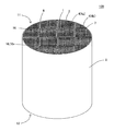
本発明のハニカム構造体の第一実施形態は、図1〜図5に示すように、複数個の角柱状のハニカムセグメント4と、接合層6と、を備えた、ハニカム構造体100である。本実施形態のハニカム構造体100は、所謂、セグメント構造のハニカム構造体である。ハニカム構造体100の外周には、複数個のハニカムセグメント4を囲繞するように配設された外壁8を更に備えている。本実施形態のハニカム構造体100は、排ガス中に含まれる粒子状物質を除去するための捕集フィルタとして好適に利用することができる。
(1) Honeycomb structure:
As shown in FIGS. 1 to 5, the first embodiment of the honeycomb structure of the present invention is the
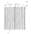
ここで、図1は、本発明のハニカム構造体の第一実施形態を模式的に示す流入端面側から見た斜視図である。図2は、図1に示すハニカム構造体の流入端面を模式的に示す平面図である。図3は、図1に示すハニカム構造体の流入端面の一部を拡大した拡大平面図である。図4は、本発明のハニカム構造体の第一実施形態における接合層の配列状態を説明するための模式図である。図5は、図3のA−A’断面を模式的に示す断面図である。なお、図4においては、ハニカムセグメントに形成された隔壁及びセルを捨象した形で作図している。 Here, FIG. 1 is a perspective view schematically showing the first embodiment of the honeycomb structure of the present invention as viewed from the inflow end face side. FIG. 2 is a plan view schematically showing an inflow end surface of the honeycomb structure shown in FIG. FIG. 3 is an enlarged plan view of a part of the inflow end face of the honeycomb structure shown in FIG. FIG. 4 is a schematic view for explaining the arrangement state of the bonding layers in the first embodiment of the honeycomb structure of the present invention. FIG. 5 is a cross-sectional view schematically showing a cross section taken along the line AA'of FIG. In FIG. 4, the partition walls and cells formed in the honeycomb segment are abstracted.
ハニカムセグメント4は、流体が流入する流入端面11から、流体が流出する流出端面12まで延びる複数のセル2を区画形成する多孔質の隔壁1、及び最外周に配設されたセグメント外周壁3を有するものである。図1〜図5に示すように、ハニカム構造体100は、複数個のハニカムセグメント4を備え、この複数個のハニカムセグメント4の側面同士が接合層6を介して接合されている。本実施形態のハニカム構造体100において、複数個のハニカムセグメント4は、セル2の延びる方向に直交する断面の形状が同一の完全セグメント4a、及び断面の形状が完全セグメント4aの一部の形状である不完全セグメント4bを、それぞれ複数個含んでいる。例えば、図1及び図2に示すように、複数個のハニカムセグメント4のうち、ハニカム構造体100の中央部分に配置されたハニカムセグメント4は、流入端面11から流出端面12に向かう方向を軸方向とする「角柱状」を呈するものとなっている。このような中央部分に配置された角柱状を呈するハニカムセグメント4が、完全セグメント4aである。一方で、複数個のハニカムセグメント4のうち、外壁8と接している外周部分に配置されたハニカムセグメント4は、角柱状に形成されたハニカムセグメント4の一部が、外壁8の形状に沿って研削された柱状のものとなっている。このような外周部分に配置されたハニカムセグメント4が、不完全セグメント4bである。
The
接合層6は、複数個のハニカムセグメント4の側面同士を互いに接合する接合材によって構成されたものである。複数個のハニカムセグメント4が接合層6を介して接合された接合体を、ハニカムセグメント接合体7ということがある。
The
接合層6は、ハニカムセグメント接合体7のセル2の延びる方向に直交する断面において、複数個の部分接合層16が、ハニカムセグメント接合体7の周縁の一の点から他の点まで延びるように配列した複数の列を有する。部分接合層16とは、対向配置された2つのハニカムセグメント4,4の相互間に配置された接合層6の一部を構成する要素である。したがって、接合層6は、部分接合層16の集合体であるといえる。それぞれの部分接合層16は、交差する2つの列の接合層6の交点を介して相互に連続しており、ハニカムセグメント接合体7において、接合層6は1つの構造物として存在している。例えば、図2に示す接合層6は、例えば、縦の列と横の列とが格子状に配列した複数の列を有する。
The
本実施形態のハニカム構造体100において、それぞれの列の接合層6は、以下のように構成されている。ここで、一の方向に配列した複数個の部分接合層16のうち、セル2の延びる方向に直交する断面における最外周に配置された部分接合層16を、最外周部分接合層16xとする。それぞれの列の接合層6は、最外周部分接合層16x(図4における「部分接合層16a」)と、他の部分接合層16b,16c,16dのうちの少なく1つとが、一の方向の延長線上において相互に重ならないように配置されていることを特徴とする。例えば、図4に示す例では、紙面の1番上に配置された部分接合層16a(即ち、最外周部分接合層16x)と、紙面の上から2番目に配置された他の部分接合層16bとが、一の方向Xの延長線上において相互に重ならないように配置されている。このように、本発明における「複数個の部分接合層16が配列した列」とは、上述したような、少なくとも1つの最外周部分接合層16xがずれた状態となっている列を含む概念である。
In the
本実施形態のハニカム構造体100は、せん断応力による接合層16の破損を有効に抑制することができる。したがって、例えば、ハニカム構造体100を缶体内に収納した時や、缶体内に収納された状態での使用時において、接合層6に対して局所的なせん断力が付与されたとしても、接合層6の破損を有効に抑制することができる。
The
複数個のハニカムセグメント4のそれぞれは、隣り合うハニカムセグメント4,4同士の互いに対向する側面のずれ量が、完全セグメント4aの側面の1辺の長さに対して、10%以下である。このように構成することによって、本実施形態のハニカム構造体100は、耐熱衝撃性に優れたものとなる。「隣り合うハニカムセグメント4,4同士の互いに対向する側面のずれ量」とは、図3において、符号Yで示される範囲の長さを意味する。すなわち、「ずれ量Y」は、隣り合うハニカムセグメント4,4に対して、更に他のハニカムセグメント4が侵入している部分の長さを意味する。したがって、「一方向に配列した部分接合層16によって構成される列」において、隣り合うハニカムセグメント4,4の「ずれ比率」が10%以下となる範囲であれば、各列を構成する部分接合層16のうちの少なくとも1つが、当該列からはみ出していてもよい。以下、「ずれ比率」について説明する。
In each of the plurality of
完全セグメント4aの側面の1辺の長さZに対する、隣り合うハニカムセグメント4,4同士の互いに対向する側面のずれ量Yの比の百分率(Y/Z×100)を、以下、隣り合うハニカムセグメント4,4の「ずれ比率」ということがある。本実施形態のハニカム構造体100においては、隣り合うハニカムセグメント4,4の「ずれ比率」が、10%以下である。隣り合うハニカムセグメント4,4の「ずれ比率」が10%を超えると、部分接合層16の延長線上で、各ハニカムセグメント4にクラックが発生し易くなることがある。
The percentage (Y / Z × 100) of the ratio of the deviation amount Y of the side surfaces of the
本明細書において、「一の方向Xの延長線上において相互に重ならない」とは、以下のような状態のことを意味する。まず、図4において、紙面の上下方向を、方向Xとする。図4において、4つの部分接合層16のそれぞれは、2つのハニカムセグメント4,4の相互間に配置されている。また、4つの部分接合層16のそれぞれは、方向Xと略平行に配置されている。例えば、部分接合層16aを方向Xに沿って移動させた際に、他の部分接合層16b,16c,16dのうちの少なくとも1つと重ならないものが存在することを、「一の方向Xの延長線上において相互に重ならない」という。本実施形態のハニカム構造体100においては、一の方向における両端の最外周部分接合層16xのうちの少なくとも一方が、他の部分接合層16(もう一方の最外周部分接合層16xを含む)と、一の方向Xの延長線上において相互に重ならない状態にある。例えば、図4において、部分接合層16bと部分接合層16c、又は、部分接合層16cと部分接合層16dについては、方向Xの延長線上において重なっている。
In the present specification, "they do not overlap each other on the extension line of one direction X" means the following states. First, in FIG. 4, the vertical direction of the paper surface is defined as the direction X. In FIG. 4, each of the four partial bonding layers 16 is arranged between the two
また、図4においては、方向Xの延長線上において、部分接合層16a,16b,16c,16dの4つは、紙面の下側に向かって左右方向に交互にずれた状態で配置されている。各部分接合層16a,16b,16c,16dの配置、別言すれば、それぞれのずれの方向については、図4に限定されることはない。接合層の配列状態の他の例として、図6〜図8のような配列状態を挙げることができる。ここで、図6〜図8は、接合層の配列状態の他の例を説明するための模式図である。
Further, in FIG. 4, on the extension line of the direction X, the four
図6においては、4つの部分接合層16a,16b,16c,16dの全てが、紙面の下側に向かって左方向にずれた状態で配置されている。紙面の上下方向に隣接する2つの部分接合層16,16は、方向Xの延長線上においてそれぞれ相互に重なるように配置されている。ただし、一方の最外周部分接合層16xである部分接合層16aと、もう一方の最外周部分接合層16xである部分接合層16dとを見た場合、この2つ部分接合層16a,16dは、相互に重ならない状態となっている。
In FIG. 6, all of the four
図7においては、紙面の上から2番目に配置された部分接合層16bと、紙面の1番下に配置された部分接合層16d(即ち、最外周部分接合層16x)とが、方向Xの延長線上において相互に重ならない状態となっている。
In FIG. 7, the
図8においては、部分接合層16a,16b,16dの3つの部分接合層は、方向Xの延長線上において、完全に一致するように配置されており、部分接合層16cのみが、紙面の右方向にずれた状態で配置されている。そして、部分接合層16cは、部分接合層16a,16b,16dの3つの部分接合層に対して、方向Xの延長線上において相互に重ならない状態となっている。このため、図8に示す例では、紙面の1番上に配置された最外周部分接合層16x及び紙面の1番下に配置された最外周部分接合層16xに対して、部分接合層16cが、方向Xの延長線上において相互に重ならない状態となっている。このように、方向Xの延長線上において相互に重ならない状態の部分接合層16が少なくとも1組ある場合には、その他の部分接合層16については、方向Xの延長線上において一致するように配置されていてもよい。
In FIG. 8, the three
図1〜図5に示すような本実施形態のハニカム構造体100において、部分接合層16の幅T1については特に制限はない。例えば、部分接合層16のそれぞれの幅T1については、0.5〜3.0mmであることが好ましく、0.5〜2.5mmであることが更に好ましく、0.5〜1.5mmであることが特に好ましい。部分接合層16の幅T1とは、「複数個の部分接合層16が配列する方向X」に対して直交する方向における、部分接合層16の幅のことを意味する。部分接合層16の幅T1が0.5mm未満であると、耐熱衝撃性の点で好ましくない。また、部分接合層16の幅T1が3.0mmを超えると、せん断強度の点で好ましくない。
In the
図4に示すように、部分接合層16a,16b,16c,16dのそれぞれは、方向Xと略平行に配置されている。ここで、「略平行」とは、方向Xに対して±15°の範囲のことをいう。このため、部分接合層16a,16b,16c,16dのそれぞれについては、方向Xに対して±15°の範囲内において、僅かに傾いた状態で配置されていてもよい。また、「方向X」とは、図2に示すようなハニカムセグメント接合体7を構成する接合層6において、ハニカムセグメント接合体7の周縁の一の点から、当該接合層6の周縁の他の点を結んで描かれる直線の延びる方向とする。図2においては、大まかに、紙面の上下方向(X方向)に延びる接合層6と、紙面の左右方向(Y方向)に延びる接合層6とが、格子状に配置されている。
As shown in FIG. 4, each of the
接合層6の幅T2については、「相互に重ならない2つの部分接合層16の幅」と、「隣り合うハニカムセグメント4,4同士の互いに対向する側面のずれ量」と、によってその値が決定される。即ち、相互に最も離れた2つの部分接合層16のそれぞれの幅と、隣り合うハニカムセグメント4,4同士の互いに対向する側面のずれ量との合計値が、「接合層6の幅T2」となる。
The value of the width T2 of the
本実施形態のハニカム構造体においては、接合層を構成する複数の列のうち、一の方向に平行な全ての列において、最外周部分接合層と、他の部分接合層のうちの少なく1つとが、各列の延長線上において相互に重ならないように配置されている。例えば、図2においては、紙面の上下方向(X方向)に延びる接合層6の全ての列において、一の部分接合層16と他の部分接合層16とが、各列の延長線上において相互に重ならないように配置されている。このように構成することによって、せん断応力による接合層6の破損を特に有効に抑制することができる。
In the honeycomb structure of the present embodiment, among the plurality of rows constituting the joint layer, in all the rows parallel to one direction, the outermost peripheral partial joint layer and at least one of the other partial joint layers are used. However, they are arranged so as not to overlap each other on the extension line of each row. For example, in FIG. 2, in all the rows of the
本実施形態のハニカム構造体においては、接合層の全ての列において、最外周部分接合層と、他の部分接合層のうちの少なく1つとが、各列の延長線上において相互に重ならないように配置されていることが好ましい。例えば、接合層の全ての列とは、例えば、図2における紙面の上下方向(X方向)及び左右方向(Y方向)に延びる接合層6の列のことである。このように構成することによって、せん断応力による接合層6の破損を極めて有効に抑制することができる。
In the honeycomb structure of the present embodiment, in all the rows of the joint layer, the outermost partial joint layer and at least one of the other partial joint layers do not overlap each other on the extension line of each row. It is preferably arranged. For example, all the rows of the bonding layers are, for example, the rows of the bonding layers 6 extending in the vertical direction (X direction) and the horizontal direction (Y direction) of the paper surface in FIG. With such a configuration, damage to the
ハニカム構造体の全体形状については、特に制限はない。例えば、図1に示すハニカム構造体100の全体形状は、流入端面11及び流出端面12が円形の円柱形状である。その他、図示は省略するが、ハニカム構造体の全体形状としては、流入端面及び流出端面が、楕円形やレーストラック(Racetrack)形や長円形等の略円形の柱形状であってもよい。また、ハニカム構造体の全体形状としては、流入端面及び流出端面が、四角形や六角形等の多角形の角柱形状であってもよい。
There are no particular restrictions on the overall shape of the honeycomb structure. For example, the overall shape of the
ハニカムセグメントの形状については、特に制限はない。例えば、ハニカムセグメントの形状として、当該ハニカムセグメントの軸方向に直交する断面形状が四角形の角柱形状を挙げることができる。なお、ハニカム構造体の最外周に配設されるハニカムセグメントは、ハニカム構造体の全体形状に応じて、角柱形状の一部が研削等により加工されたものであってもよい。 The shape of the honeycomb segment is not particularly limited. For example, as the shape of the honeycomb segment, a prism shape having a quadrangular cross-sectional shape orthogonal to the axial direction of the honeycomb segment can be mentioned. The honeycomb segment arranged on the outermost circumference of the honeycomb structure may be a part of the prismatic shape processed by grinding or the like according to the overall shape of the honeycomb structure.
各ハニカムセグメントの隔壁の厚さが、50〜600μmであることが好ましく、100〜500μmであることが更に好ましく、150〜450μmであることが特に好ましい。隔壁の厚さが、50μm未満であると、ハニカム構造体のアイソスタティック強度(Isostatic strength)が低下してしまうことがある。隔壁の厚さが、600μmを超えると、圧力損失が増大し、エンジンの出力低下や燃費の悪化を引き起こすことがある。隔壁の厚さは、ハニカム構造体の軸方向に直交する断面を光学顕微鏡により観察する方法で測定した値である。 The thickness of the partition wall of each honeycomb segment is preferably 50 to 600 μm, more preferably 100 to 500 μm, and particularly preferably 150 to 450 μm. If the thickness of the partition wall is less than 50 μm, the isostatic strength of the honeycomb structure may decrease. If the thickness of the partition wall exceeds 600 μm, the pressure loss increases, which may cause a decrease in engine output and deterioration in fuel efficiency. The thickness of the partition wall is a value measured by a method of observing a cross section of the honeycomb structure orthogonal to the axial direction with an optical microscope.
各ハニカムセグメントにおいて、隔壁によって区画形成されるセルのセル密度が、5〜100個/cm2であることが好ましく、10〜90個/cm2であることが更に好ましい。このように構成することによって、本実施形態のハニカム構造体を、排ガス浄化用触媒担体やフィルタ等として好適に利用することができる。 In each honeycomb segment, the cell density of the cells partitioned by the partition walls is preferably 5 to 100 cells / cm 2 , and more preferably 10 to 90 cells / cm 2 . With this configuration, the honeycomb structure of the present embodiment can be suitably used as a catalyst carrier for exhaust gas purification, a filter, or the like.
隔壁の気孔率は、例えば、20〜90%であることが好ましく、25〜80%であることが更に好ましく、30〜75%であることが特に好ましい。隔壁の気孔率が20%未満であると、圧力損失が増大し、エンジンの出力低下や燃費の悪化を引き起こすことがある。また、90%を超えると、ハニカム構造体のアイソスタティック強度が低下してしまうことがある。隔壁の気孔率は、水銀ポロシメーター(Mercury porosimeter)によって計測された値とする。水銀ポロシメーターとしては、例えば、Micromeritics社製のAutopore 9500(商品名)を挙げることができる。 The porosity of the partition wall is, for example, preferably 20 to 90%, more preferably 25 to 80%, and particularly preferably 30 to 75%. If the porosity of the partition wall is less than 20%, the pressure loss increases, which may cause a decrease in engine output and a deterioration in fuel efficiency. On the other hand, if it exceeds 90%, the isostatic strength of the honeycomb structure may decrease. The porosity of the partition wall shall be a value measured by a mercury porosimeter. Examples of the mercury porosimeter include Autopore 9500 (trade name) manufactured by Micromeritics.
各ハニカムセグメントに形成されるセルの形状については特に制限はない。例えば、セルの延びる方向に直交する断面における、セルの形状としては、多角形、円形、楕円形等を挙げることができる。多角形としては、三角形、四角形、五角形、六角形、八角形等を挙げることができる。また、セルの形状については、全てのセルの形状が同一形状であってもよいし、異なる形状であってもよい。例えば、四角形のセルと、八角形のセルと混在したものであってもよい。また、セルの大きさについては、全てのセルの大きさが同じであってもよいし、異なっていてもよい。例えば、複数のセルのうち、一部のセルの大きさを大きくし、他のセルの大きさを相対的に小さくしてもよい。 The shape of the cells formed in each honeycomb segment is not particularly limited. For example, the shape of the cell in the cross section orthogonal to the extending direction of the cell may be a polygon, a circle, an ellipse, or the like. Examples of the polygon include a triangle, a quadrangle, a pentagon, a hexagon, and an octagon. Further, regarding the cell shape, the shapes of all the cells may be the same shape or different shapes. For example, it may be a mixture of quadrangular cells and octagonal cells. Further, regarding the cell size, the size of all cells may be the same or different. For example, among a plurality of cells, the size of some cells may be increased and the size of other cells may be relatively reduced.
ハニカムセグメントを構成する材料に特に制限はないが、強度、耐熱性、耐久性等の観点から、主成分は、酸化物又は非酸化物の各種セラミックスや金属等であることが好ましい。具体的には、例えば、セラミックスとしては、コージェライト、ムライト(Mullite)、アルミナ、スピネル(Spinel)、炭化珪素、窒化珪素、及びチタン酸アルミニウム等が考えられる。金属としては、Fe−Cr−Al系金属、及び金属珪素等が考えられる。これらの材料の中から選ばれた1種又は2種以上を主成分とすることが好ましい。高強度、高耐熱性等の観点から、アルミナ、ムライト、チタン酸アルミニウム、コージェライト、炭化珪素、及び窒化珪素から構成された群より選ばれた1種又は2種以上を主成分とすることが特に好ましい。また、高熱伝導率や高耐熱性等の観点からは、炭化珪素、又は珪素−炭化珪素複合材料が特に適している。ここで、「主成分」とは、ハニカムセグメントを構成する材料中に、50質量%以上の比率で含有されている成分のことを意味する。なお、この主成分は、ハニカムセグメントを構成する材料中に、70質量%以上の比率で含有されていることが好ましく、80%以上の比率で含有されていることが更に好ましい。 The material constituting the honeycomb segment is not particularly limited, but from the viewpoint of strength, heat resistance, durability and the like, the main component is preferably oxide or non-oxide ceramics or metal. Specifically, for example, as ceramics, cordierite, mullite, alumina, spinel, silicon carbide, silicon nitride, aluminum titanate and the like can be considered. As the metal, Fe-Cr-Al-based metal, metallic silicon, and the like can be considered. It is preferable to use one or more selected from these materials as the main component. From the viewpoint of high strength, high heat resistance, etc., one or more kinds selected from the group composed of alumina, mullite, aluminum titanate, corderite, silicon carbide, and silicon nitride may be the main component. Especially preferable. Further, from the viewpoint of high thermal conductivity and high heat resistance, silicon carbide or a silicon-silicon carbide composite material is particularly suitable. Here, the "main component" means a component contained in the material constituting the honeycomb segment at a ratio of 50% by mass or more. The main component is preferably contained in the material constituting the honeycomb segment in a ratio of 70% by mass or more, and more preferably 80% or more.
次に、本発明のハニカム構造体の第二実施形態について、図9〜図12を参照しつつ説明する。図9〜図12に示すように、本実施形態のハニカム構造体200は、複数個の角柱状のハニカムセグメント4と、接合層6と、を備えた、ハニカム構造体200である。そして、ハニカム構造体200においては、ハニカムセグメント4に形成されたセル2のいずれか一方の開口部を目封止するように配設された目封止部5を、更に備えている。即ち、ハニカム構造体200は、複数のセル2の流入端面11側又は流出端面12側のいずれか一方の端部に目封止部5が配設されたハニカムフィルタとなっている。本実施形態のハニカム構造体200において、ハニカムセグメント4及び接合層6については、これまでに説明した第一実施形態のハニカム構造体と同様に構成されていることが好ましい。
Next, a second embodiment of the honeycomb structure of the present invention will be described with reference to FIGS. 9 to 12. As shown in FIGS. 9 to 12, the
ここで、図9は、本発明のハニカム構造体の第二実施形態を模式的に示す流入端面側から見た斜視図である。図10は、図9に示すハニカム構造体の流入端面を模式的に示す平面図である。図11は、図9に示すハニカム構造体の流入端面の一部を拡大した拡大平面図である。図12は、図11のB−B’断面を模式的に示す断面図である。図9〜図12において、図1〜図5に示すハニカム構造体100と同様の構成要素については、同一の符号を付して説明を省略することがある。
Here, FIG. 9 is a perspective view schematically showing the second embodiment of the honeycomb structure of the present invention as viewed from the inflow end face side. FIG. 10 is a plan view schematically showing the inflow end surface of the honeycomb structure shown in FIG. FIG. 11 is an enlarged plan view of a part of the inflow end surface of the honeycomb structure shown in FIG. FIG. 12 is a cross-sectional view schematically showing a BB'cross section of FIG. 9 to 12, the same components as those of the
図9〜図12に示すように、目封止部5は、それぞれのハニカムセグメント4に形成されたセル2の流入端面11側又は流出端面12側のいずれか一方の開口部を封止するように配設されている。例えば、目封止部5は、それぞれのハニカムセグメント4の流入端面11における所定のセル2の開口部、及び流出端面12における所定のセル2以外の残余のセル2の開口部に配設されている。以下、複数のセル2のうち、流出端面12側の開口部に目封止部5が配設され、流入端面11側が開口したセル2を、流入セル2aとする。また、複数のセル2のうち、流入端面11側の開口部に目封止部5が配設され、流出端面12側が開口したセル2を、流出セル2bとする。本実施形態のハニカム構造体200は、排ガス浄化用のフィルタ、特に、自動車のエンジンから排出される排ガスを浄化するためのフィルタとして好適に用いることができる。
As shown in FIGS. 9 to 12, the sealing
本実施形態のハニカム構造体において、流入セルの形状と、流出セルの形状とは同じであってもよいし、流入セルの形状と、流出セルの形状とが異なっていてもよい。例えば、流入セルの形状を八角形とし、流出セルの形状を四角形としてもよい。また、セルの大きさについては、全てのセルの大きさが同じであってもよいし、異なっていてもよい。例えば、複数のセルのうち、流入セルの大きさを大きくし、流出セルの大きさを、流入セルの大きさに比して相対的に小さくしてもよい。また、逆に、複数のセルのうち、流入セルの大きさを小さくし、流出セルの大きさを、流入セルの大きさに比して相対的に大きくしてもよい。更に、流入セルの中にも、大きさが異なるセルが混在していてもよい。流出セルの中にも、大きさが異なるセルが混在していてもよい。 In the honeycomb structure of the present embodiment, the shape of the inflow cell and the shape of the outflow cell may be the same, or the shape of the inflow cell and the shape of the outflow cell may be different. For example, the shape of the inflow cell may be octagonal, and the shape of the outflow cell may be quadrangular. Further, regarding the cell size, the size of all cells may be the same or different. For example, among the plurality of cells, the size of the inflow cell may be increased, and the size of the outflow cell may be made relatively smaller than the size of the inflow cell. On the contrary, among the plurality of cells, the size of the inflow cell may be reduced and the size of the outflow cell may be made relatively larger than the size of the inflow cell. Further, cells having different sizes may coexist in the inflow cells. Cells of different sizes may coexist in the outflow cells.
ハニカム構造体における、流入セルと流出セルとの配置については特に制限はないが、1個の流入セルに対して、少なくとも1個の流出セルが、隔壁を隔てて離接するように配置されていることが好ましい。例えば、セルの形状が四角形の場合には、流入セルと流出セルとが隔壁を隔てて交互に配置され、ハニカム構造体の両端面が相補的な市松模様を呈するように構成されていることが好ましい。 The arrangement of the inflow cell and the outflow cell in the honeycomb structure is not particularly limited, but at least one outflow cell is arranged so as to be separated and separated from each other with respect to one inflow cell. Is preferable. For example, when the cell shape is quadrangular, the inflow cell and the outflow cell are alternately arranged with a partition wall in between, and both end faces of the honeycomb structure are configured to have a complementary checkered pattern. preferable.
(2)ハニカム構造体の製造方法:
次に、本発明のハニカム構造体を製造する方法について説明する。なお、本発明のハニカム構造体を製造する方法については、以下に説明する製造方法に限定されることはない。
(2) Manufacturing method of honeycomb structure:
Next, a method for manufacturing the honeycomb structure of the present invention will be described. The method for producing the honeycomb structure of the present invention is not limited to the production method described below.
まず、本発明のハニカム構造体を製造する際には、ハニカムセグメントを作製するための可塑性の坏土を調製する。ハニカムセグメントを作製するための坏土は、原料粉末として、前述のハニカムセグメントの好適な材料の中から選ばれた材料に、適宜、バインダ等の添加剤、及び水を添加することによって調製することができる。 First, when producing the honeycomb structure of the present invention, a plastic clay for producing a honeycomb segment is prepared. The clay for producing the honeycomb segment is prepared by appropriately adding an additive such as a binder and water to a material selected from the above-mentioned suitable materials for the honeycomb segment as a raw material powder. Can be done.
次に、このようにして得られた坏土を押出成形することにより、複数のセルを区画形成する隔壁、及び最外周に配設されたセグメント外周壁を有する、角柱状のハニカム成形体を作製する。ハニカム成形体は、複数個作製する。 Next, by extruding the clay thus obtained, a prismatic honeycomb molded body having a partition wall for partitioning a plurality of cells and a segment outer peripheral wall arranged on the outermost circumference is produced. To do. A plurality of honeycomb molded bodies are produced.
得られたハニカム成形体を、例えば、マイクロ波及び熱風で乾燥する。次に、ハニカム成形体の作製に用いた材料と同様の材料で、セルの開口部を目封止することで目封止部を作製する。目封止部を作製した後に、ハニカム成形体を更に乾燥してもよい。 The obtained honeycomb molded body is dried by, for example, microwaves and hot air. Next, the eye-sealing portion is produced by sealing the opening of the cell with the same material as the material used for producing the honeycomb molded body. After producing the mesh sealing portion, the honeycomb molded body may be further dried.
次に、目封止部を作製したハニカム成形体を焼成することにより、多孔質の隔壁を有するハニカムセグメントを得る。焼成温度及び焼成雰囲気は原料により異なり、当業者であれば、選択された材料に最適な焼成温度及び焼成雰囲気を選択することができる。 Next, a honeycomb segment having a porous partition wall is obtained by firing the honeycomb molded body in which the mesh sealing portion is produced. The firing temperature and firing atmosphere differ depending on the raw material, and a person skilled in the art can select the optimum firing temperature and firing atmosphere for the selected material.
次に、得られた複数個のハニカムセグメントを、接合材を用いて互いに接合し、乾燥硬化させた後、所望の形状となるよう外周を加工することによって、セグメント構造のハニカム構造体を得る。複数個のハニカムセグメントを接合する方法として、例えば、図13に示す(a)〜(d)に示すような方法を挙げることができる。図13は、ハニカムセグメントを接合してハニカム構造体を作製する方法を説明するための説明図である。図13においては、(a)〜(d)に示す順番にて、ハニカムセグメントを接合してハニカム構造体を作製する。 Next, the obtained plurality of honeycomb segments are joined to each other using a bonding material, dried and cured, and then the outer circumference is processed so as to have a desired shape to obtain a honeycomb structure having a segment structure. As a method of joining a plurality of honeycomb segments, for example, the methods shown in FIGS. 13A to 13D can be mentioned. FIG. 13 is an explanatory diagram for explaining a method of joining honeycomb segments to form a honeycomb structure. In FIG. 13, honeycomb segments are joined in the order shown in (a) to (d) to prepare a honeycomb structure.
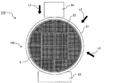
まず、図13の(a)に示すように、端面の形状が四角形のハニカムセグメント34と、端面の形状が三角形のハニカムセグメント44とを、それぞれ必要な個数用意する。以下、端面の形状が四角形のハニカムセグメント34を、四角セグメント34ということがある。また、端面の形状が三角形のハニカムセグメント44を、三角セグメント44ということがある。三角セグメント44は、ハニカムセグメント34,44を接合してハニカムセグメント接合体37を作製する際に、ハニカムセグメント接合体37の四隅に配置されるハニカムセグメントである。三角セグメント44には、端面の形状が三角形のスペーサ41を配置する。そして、四角セグメント34と三角セグメント44とを接合層36を介して接合する。スペーサ41は、接合時に三角セグメント44に対して力を加えるためのものであり、このスペーサ41のサイズは、三角セグメント44よりも少し大きいサイズとする。スペーサ41のサイズを大きくすることにより、ハニカムセグメント34,44の接合時に、三角セグメント44に対して、ハニカムセグメント34,44同士が剥がれず適切に接合するために十分な大きさの力を良好に加えることができる。
First, as shown in FIG. 13A, a required number of
次に、図13の(b)に示すように、四角セグメント34と三角セグメント44との接合時において、ハニカムセグメント接合体37の4方向から力を加える。具体的には、図13の(b)のように、ハニカムセグメント接合体37の4方向の各側面に、板状部材42をそれぞれ配置し、それぞれの板状部材42に対して力を加える。この際、4方向から加える力は、異なる荷重とする。例えば、図13の(b)の例では、接合時において、紙面の上方から下方に掛かる荷重を、その他の方向に掛かる荷重よりも大きくしている。このような工程を行うことで、ハニカムセグメント接合体37において、四隅に配置される三角セグメント44に対して意図的な位置ずれを起こさせて、接合層36にずれを生じさせることができる。
Next, as shown in FIG. 13B, when the
4方向から加える力を調節し、接合層36に必要な大きさのずれを生じさせた後、板状部材42及びスペーサ41を取り除いて、図13の(c)に示すような、ハニカムセグメント接合体37を得る。
After adjusting the force applied from the four directions to cause a deviation of the required size in the
次に、図13の(d)に示すように、得られたハニカムセグメント接合体37の外周を加工し、加工したハニカムセグメント接合体37の加工面に外周コート材を塗工して外壁38を形成することが好ましい。外周コート材の材料としては、例えば、接合材の材料と同じ材料を用いることができる。以上のようにして、本発明のハニカム構造体を製造することができる。
Next, as shown in FIG. 13D, the outer circumference of the obtained honeycomb segment joint 37 is processed, and the outer peripheral coating material is applied to the processed surface of the processed honeycomb segment joint 37 to form the
(実施例1)
まず、炭化珪素粉末を80質量部と、Si粉末を20質量部とを混合して、混合粉末を得た。この混合粉末に、バインダ、造孔材、及び水を添加して、混合、混練して坏土を調製した。
(Example 1)
First, 80 parts by mass of silicon carbide powder and 20 parts by mass of Si powder were mixed to obtain a mixed powder. A binder, a pore-forming material, and water were added to this mixed powder, and the mixture was mixed and kneaded to prepare a clay.
次に、ハニカム成形体作製用の口金を用いて坏土を押出成形し、全体形状が四角柱状のハニカム成形体を得た。ハニカム成形体は、16個作製した。 Next, the clay was extruded using a base for producing a honeycomb molded body to obtain a honeycomb molded body having a square columnar shape as a whole. 16 honeycomb molded bodies were produced.
次に、ハニカム成形体をマイクロ波乾燥機で乾燥し、更に熱風乾燥機で完全に乾燥させた後、ハニカム成形体の両端面を切断し、所定の寸法に整えた。 Next, the honeycomb molded body was dried with a microwave dryer, and further dried completely with a hot air dryer, and then both end faces of the honeycomb molded body were cut and adjusted to a predetermined size.
次に、乾燥したハニカム成形体に、目封止部を形成した。具体的には、まず、ハニカム成形体の流入端面に、流入セルが覆われるようにマスクを施した。その後、マスクの施されたハニカム成形体の端部を、目封止スラリーに浸漬し、マスクが施されていない流出セルの開口部に目封止スラリーを充填した。その後、ハニカム成形体の流出端面についても、上記と同様の方法で、流入セルの開口部に目封止スラリーを充填した。その後、目封止部を形成したハニカム成形体を、更に、熱風乾燥機で乾燥した。 Next, a mesh sealing portion was formed on the dried honeycomb molded body. Specifically, first, the inflow end face of the honeycomb molded body was masked so as to cover the inflow cell. Then, the end portion of the masked honeycomb molded body was immersed in the sealing slurry, and the opening of the unmasked outflow cell was filled with the sealing slurry. After that, the outflow end face of the honeycomb molded body was also filled with the sealing slurry at the opening of the inflow cell by the same method as described above. Then, the honeycomb molded body in which the mesh sealing portion was formed was further dried with a hot air dryer.
次に、目封止部を形成したハニカム成形体を脱脂し、焼成してハニカムセグメントを得た。脱脂の条件は、550℃で3時間とした。焼成の条件は、アルゴン雰囲気下で、1450℃、2時間とした。ハニカムセグメントは、全体形状が四角柱状であった。ハニカムセグメントの端面の形状は、一辺の長さが36mmの正方形であった。このハニカムセグメントが、ハニカム構造体における「完全セグメント」となる。表2の「セグメントサイズ」の欄に、この完全セグメントの一辺の長さを示す。 Next, the honeycomb molded body on which the mesh sealing portion was formed was degreased and fired to obtain a honeycomb segment. The degreasing condition was 550 ° C. for 3 hours. The firing conditions were 1450 ° C. for 2 hours under an argon atmosphere. The honeycomb segment had a square columnar shape as a whole. The shape of the end face of the honeycomb segment was a square with a side length of 36 mm. This honeycomb segment becomes a "perfect segment" in the honeycomb structure. The length of one side of this complete segment is shown in the "Segment size" column of Table 2.
次に、得られたハニカムセグメントを、互いの側面同士が対向するように隣接して配置された状態で、接合材によって接合し、ハニカム接合体を作製した。ハニカム接合体は、その端面において、縦方向に4個、横方向に4個の合計16個のハニカムセグメントが配列するように接合して作製した。表1の「セグメント数」の欄は、各実施例に用いたハニカムセグメントの数を示す。例えば、「セグメント数」の欄に、「4×4」と記載されている場合には、縦方向に4個、横方向に4個の合計16個のハニカムセグメントを用いたことを意味する。ハニカムセグメントを接合する際には、図13に示すような方法によって、接合層に意図的なずれを生じさせた。 Next, the obtained honeycomb segments were joined with a joining material in a state where the side surfaces of the obtained honeycomb segments were adjacent to each other so as to face each other, to prepare a honeycomb joint. The honeycomb joint was produced by joining so that a total of 16 honeycomb segments, four in the vertical direction and four in the horizontal direction, were arranged on the end face thereof. The “Number of segments” column in Table 1 indicates the number of honeycomb segments used in each embodiment. For example, when "4 x 4" is described in the "number of segments" column, it means that a total of 16 honeycomb segments, 4 in the vertical direction and 4 in the horizontal direction, are used. When joining the honeycomb segments, the joining layer was intentionally displaced by the method shown in FIG.
次に、得られたハニカム接合体の外周面を研削加工した。その後、研削加工したハニカム接合体の側面に、外周コート材を塗工して外周コート層を形成した。以上のようにして、実施例1のハニカム構造体を作製した。 Next, the outer peripheral surface of the obtained honeycomb joint was ground. Then, an outer peripheral coating material was applied to the side surface of the ground honeycomb joint to form an outer peripheral coating layer. As described above, the honeycomb structure of Example 1 was produced.
実施例1のハニカム構造体は、端面の全体形状が円形であり、この端面の直径が143.8mmであった。表1の「断面形状」の欄に、ハニカム構造体の端面の全体形状を示す。また、表1の「直径」の欄に、ハニカム構造体の端面の直径を示す。ハニカム構造体のセルの延びる方向の長さは152.4mmであった。表1の「全長」の欄に、ハニカム構造体のセルの延びる方向の長さを示す。ハニカムセグメントは、隔壁の厚さが305μmで、セル密度が46.5個/cm2で、隔壁の気孔率が41%であった。気孔率は、Micromeritics社製の水銀ポロシメーター(Autopore 9500(商品名))で測定した。表1に、各結果を示す。各ハニカムセグメントにおいて、隔壁によって区画形成されたセルの形状は、四角形のセルと八角形のセルとが交互に配置されたものであった。このようなセル形状のハニカムセグメントを用いた実施例について、表1の「セル形状」の欄に、「四角、八角」と示す。 In the honeycomb structure of Example 1, the overall shape of the end face was circular, and the diameter of the end face was 143.8 mm. The overall shape of the end face of the honeycomb structure is shown in the “Cross-sectional shape” column of Table 1. In addition, the diameter of the end face of the honeycomb structure is shown in the "Diameter" column of Table 1. The length of the honeycomb structure in the extending direction of the cell was 152.4 mm. In the "total length" column of Table 1, the length of the honeycomb structure in the extending direction is shown. In the honeycomb segment, the thickness of the partition wall was 305 μm, the cell density was 46.5 cells / cm 2 , and the porosity of the partition wall was 41%. The porosity was measured with a mercury porosimeter (Autopore 9500 (trade name)) manufactured by Micromeritics. Table 1 shows each result. In each honeycomb segment, the shape of the cells partitioned by the partition walls was such that quadrangular cells and octagonal cells were alternately arranged. An example using such a cell-shaped honeycomb segment is indicated by “square, octagon” in the “cell shape” column of Table 1.
得られたハニカム構造体は、最外周部分接合層と、他の部分接合層のうちの少なく1つとが、一の方向の延長線上において相互に重ならないように配置されたものであった。ここで、それぞれの接合層の列の配置について、図4に示すような部分接合層の配置を「a」とし、図6に示すような部分接合層の配置を「b」とし、図7に示すような部分接合層の配置を「c」とする。また、部分接合層のうちの2つの部分接合層が、一の方向の延長線上において相互に重ならないように配置されていたとしても、相互に重ならないように配置された2つの部分接合層に、最外周部分接合層が含まれない場合の配置を「d」とする。更に、部分接合層のうちの2つの部分接合層が、一の方向の延長線上において相互に重ならないように配置されたものが無い場合の配置を「e」とする。本実施例においては、接合層の列の配置を、上述した接合層を構成する部分接合層同士の重なりパターンとして、a〜eの5つのパターンに分類した。 In the obtained honeycomb structure, the outermost peripheral partial bonding layer and at least one of the other partial bonding layers were arranged so as not to overlap each other on an extension line in one direction. Here, regarding the arrangement of the rows of the respective bonding layers, the arrangement of the partial bonding layers as shown in FIG. 4 is referred to as “a”, the arrangement of the partial bonding layers as shown in FIG. 6 is defined as “b”, and FIG. The arrangement of the partially bonded layers as shown is defined as "c". Further, even if the two partial bonding layers of the partial bonding layers are arranged so as not to overlap each other on the extension line in one direction, the two partial bonding layers arranged so as not to overlap each other , The arrangement when the outermost peripheral partial bonding layer is not included is defined as "d". Further, the arrangement when two of the partial bonding layers are not arranged so as not to overlap each other on the extension line in one direction is defined as "e". In this embodiment, the arrangement of the rows of the bonding layers is classified into five patterns a to e as overlapping patterns of the partial bonding layers constituting the bonding layer described above.
実施例1のハニカム構造体は、接合層の列の配置が、a、b、及びcのうちのいずれかの配置であった。表2の「接合層の列の配置」の欄に、ハニカム構造体における接合層の列の配置を示す。 In the honeycomb structure of Example 1, the arrangement of the rows of the bonding layers was one of a, b, and c. The arrangement of the rows of the bonding layers in the honeycomb structure is shown in the column of "Arrangement of rows of the bonding layers" in Table 2.
各部分接合層の幅は、0.5〜1.5mmの範囲であった。また、隣り合うハニカムセグメント同士の互いに対向する側面の最大ずれ量は、3mmであった。隣り合うハニカムセグメント同士の互いに対向する側面の最大ずれ量を、表2の「隣り合うセグメントの最大ずれ量YMAX」の欄に示す。また、完全セグメントの一辺の長さである「セグメントサイズZ」に対する、「隣り合うセグメントの最大ずれ量YMAX」の比の百分率を、表2の「最大ずれ比率」の欄に示す。「最大ずれ比率」が10%以下であれば、隣り合うハニカムセグメント同士の互いに対向する側面のずれ量YMAXが、完全セグメントの側面の1辺の長さZに対して、10%以下となる。 The width of each partial bonding layer was in the range of 0.5 to 1.5 mm. Further, the maximum amount of deviation of the side surfaces of the adjacent honeycomb segments facing each other was 3 mm. The maximum amount of deviation between adjacent honeycomb segments facing each other is shown in the column of "Maximum amount of deviation Y MAX of adjacent segments" in Table 2. Further, the length of one side of the full segment to "segment size Z", the percentage of the ratio of "maximum displacement amount Y MAX of adjacent segments", shown in the column "Maximum deviation ratio" in Table 2. If 10% or less "maximum deviation ratio", shift amount Y MAX side surfaces facing each other of the honeycomb segments adjacent to each other, the length Z of one side of the side surface of the full segment, of 10% or less ..
(実施例2及び3)
接合層の列の配置を、表2に示すように変更して、実施例2及び3のハニカム構造体を作製した。実施例2のハニカム構造体は、接合層の列の配置が、a、及びbのうちのいずれかの配置であった。実施例3のハニカム構造体は、接合層の列の配置が、b、及びcのうちのいずれかの配置であった。隣り合うハニカムセグメント同士の互いに対向する側面の最大ずれ量YMAXは、実施例2のハニカム構造体が、2.5mmで、実施例3のハニカム構造体が、1mmであった。
(Examples 2 and 3)
The arrangement of the rows of the bonding layers was changed as shown in Table 2 to prepare the honeycomb structures of Examples 2 and 3. In the honeycomb structure of Example 2, the arrangement of the rows of the bonding layers was one of a and b. In the honeycomb structure of Example 3, the arrangement of the rows of the bonding layers was one of b and c. Maximum deviation amount Y MAX side surfaces facing each other of adjacent honeycomb segments each other, the honeycomb structure of Example 2 is at 2.5 mm, the honeycomb structure of Example 3 was 1 mm.
(実施例4〜12)
実施例4〜12においては、表1のセル構造の欄に示されるようなハニカムセグメントを複数個作製し、作製したハニカムセグメントを用いてハニカム構造体を作製した。各実施例において、表1の「セグメント数」の欄に示すような個数のハニカムセグメントを用いた。得られたハニカム構造体の「接合層の列の配置」、及び「隣り合うセグメントの最大ずれ量YMAX」、及び「最大ずれ比率」を表2に示す。
(Examples 4 to 12)
In Examples 4 to 12, a plurality of honeycomb segments as shown in the cell structure column of Table 1 were produced, and a honeycomb structure was produced using the produced honeycomb segments. In each example, the number of honeycomb segments as shown in the “Number of segments” column of Table 1 was used. The resulting "arrangement of rows of the bonding layer" of the honeycomb structure, and "maximum displacement amount Y MAX of adjacent segment", and "maximum deviation ratio" shown in Table 2.
実施例6及び7においては、ハニカムセグメントを接合したハニカム接合体の外周面を、端面の全体形状を楕円形となるように研削加工した。その後、研削加工したハニカム接合体の側面に、外周コート材を塗工して外周コート層を形成した。 In Examples 6 and 7, the outer peripheral surface of the honeycomb joint body to which the honeycomb segments were joined was ground so that the overall shape of the end face was elliptical. Then, an outer peripheral coating material was applied to the side surface of the ground honeycomb joint to form an outer peripheral coating layer.
(比較例1〜12)
表3に示すようなセル構造のハニカムセグメントを作製し、接合層の列の配置を、表4に示すように変更して、比較例1〜12のハニカム構造体を作製した。接合層の列の配置において、パターンd、又はパターンeが含まれている場合は、最外周部分接合層と、他の部分接合層とが、一の方向の延長線上において相互に重なっている接合層を含むこととなる。また、「最大ずれ比率」が10%を超えている場合は、隣り合うハニカムセグメント同士の互いに対向する側面の最大ずれ量YMAXが、完全セグメントの側面の1辺の長さZに対して、10%を超えることとなる。
(Comparative Examples 1 to 12)
Honeycomb segments having a cell structure as shown in Table 3 were prepared, and the arrangement of the rows of the bonding layers was changed as shown in Table 4 to prepare the honeycomb structures of Comparative Examples 1 to 12. When the pattern d or the pattern e is included in the arrangement of the rows of the joining layers, the outermost partial joining layer and the other partial joining layers are joined to each other on an extension line in one direction. It will include layers. Further, when the "maximum deviation ratio" is greater than 10%, the maximum displacement amount Y MAX side surfaces facing each other of the honeycomb segments adjacent to each other, one side of the length Z of the side surface of the full segment, It will exceed 10%.

得られた実施例1〜12及び比較例1〜12のハニカム構造体について、以下の方法で、「耐熱衝撃性(1)」、及び「せん断強度」についての評価を行った。評価結果を表2及び表4に示す。 The obtained honeycomb structures of Examples 1 to 12 and Comparative Examples 1 to 12 were evaluated for "heat impact resistance (1)" and "shear strength" by the following methods. The evaluation results are shown in Tables 2 and 4.
[耐熱衝撃性(1)]
耐熱衝撃性(1)の評価として、ハニカム構造体に以下に記載する試験を行い、試験後のハニカム構造体におけるクラックの発生の有無により、ハニカム構造体のロバスト(robust)性を評価するものとした。具体的には、2.2Lディーゼルエンジンを搭載するエンジンベンチにて、エンジン回転数2000rpm、エンジントルク60Nmの運転条件にて、2〜12g/Lの煤を、各実施例及び比較例のハニカム構造体の内部に堆積させた。その後、ポストインジェクションによる再生処理を行い、ハニカム構造体の入口ガス温度を上昇させ、ハニカム構造体の前後の圧損が低下し始めたところでポストインジェクションを切り、エンジンをアイドル状態に切り替えた。このときの煤堆積量は、実施例の各水準において、流出側端面の中央部における最高温度が1000℃となるようにし、実施例と比較例の同じ番号は同一煤量となる条件で試験を実施した。そして、ハニカム構造体の流出端面側及び流入端面側におけるクラックの有無を、それぞれ目視にて観察した。クラックが確認されない場合を合格とし、クラックが確認された場合を不合格として、流出端面側及び流入端面側のそれぞれの結果に基づいて、以下の評価基準により、耐熱衝撃性(1)の評価を行った。耐熱衝撃性(1)の評価において、流入端面側及び流出端面側が共に「合格」の場合を、評価Aとした。耐熱衝撃性(1)の評価において、流入端面側及び流出端面側の少なくとも一方が「不合格」の場合を、評価Cとした。評価結果を表2及び表4に示す。
[Heat-resistant impact resistance (1)]
As an evaluation of the heat impact resistance (1), the test described below is performed on the honeycomb structure, and the robustness of the honeycomb structure is evaluated based on the presence or absence of cracks in the honeycomb structure after the test. did. Specifically, on an engine bench equipped with a 2.2 L diesel engine, 2 to 12 g / L of soot is applied to the honeycomb structure of each example and comparative example under operating conditions of an engine speed of 2000 rpm and an engine torque of 60 Nm. It was deposited inside the body. After that, a regeneration process by post-injection was performed to raise the inlet gas temperature of the honeycomb structure, and when the pressure loss before and after the honeycomb structure began to decrease, the post-injection was turned off and the engine was switched to the idle state. The soot accumulation amount at this time was set so that the maximum temperature at the center of the outflow side end face was 1000 ° C. at each level of the example, and the test was conducted under the condition that the same number of the example and the comparative example had the same soot amount. Carried out. Then, the presence or absence of cracks on the outflow end face side and the inflow end face side of the honeycomb structure was visually observed. The case where no crack is confirmed is regarded as a pass, and the case where a crack is confirmed is regarded as a failure, and the thermal shock resistance (1) is evaluated according to the following evaluation criteria based on the results of the outflow end face side and the inflow end face side. went. In the evaluation of thermal shock resistance (1), the case where both the inflow end face side and the outflow end face side were "passed" was evaluated as evaluation A. In the evaluation of thermal shock resistance (1), the case where at least one of the inflow end face side and the outflow end face side was "failed" was evaluated as C. The evaluation results are shown in Tables 2 and 4.
[せん断強度]
図14に示すせん断強度試験機110を用い、実施例1〜12及び比較例1〜12のハニカム構造体に対してせん断強度の評価を行った。具体的には、まず、各ハニカム構造体100の外壁8の周りに緩衝用のマット22を巻き付けた。次に、緩衝用のマット22を巻き付けた状態のハニカム構造体100を、金属製の缶体21内に挿入し、せん断強度測定用の測定試料とした。マット22としては、三菱樹脂製のセラミックマット(商品名:マフテック OBM−P)を用いた。使用したマット22は、単位面積当たりの質量が1000〜1200g/m2であり、その厚さが、4.0〜5.0mmであった。このようにして作製した測定試料に対して、第一荷重方向L1、第二荷重方向L2、及び第三荷重方向L3のそれぞれから荷重を負荷し、ハニカム構造体100にせん断が発生する強度を測定した。各荷重の負荷は、ダイヤルゲージ(Dial gauge)を取り付けた荷重供給部24を、測定試料とした缶体21の一方の端面近傍の端部に押し付けることによって行った。測定試料に負荷する荷重は、せん断強度試験の負荷荷重を読み取ることによって確認した。測定試料に負荷する荷重を徐々に大きくしていき、ハニカム構造体100にせん断が発生した際の荷重を、ハニカム構造体100のせん断強度とした。
[Shear strength]
Using the
せん断強度の評価においては、基準となる比較例のハニカム構造体に対して、以下のA〜Cの3段階で評価した。ベース(basis)に対し、各方向L1,L2,L3とも、せん断強度が15%以上向上したものを、評価Aとした。せん断強度が5%以上、15%未満向上したものを、評価Bとした。せん断強度の向上が5%未満又はせん断強度の向上が見られないものを評価Cとした。ここでいうベースとは、以下の通りである。実施例1〜3及び比較例1〜3については、比較例1がベースである。実施例4、5及び比較例4、5については、比較例4がベースである。実施例6、7及び比較例6、7については、比較例6がベースである。実施例8、9及び比較例8、9については、比較例8がベースである。実施例10〜12及び比較例10〜12については、比較例10がベースである。評価結果を表2及び表4に示す。なお、図14は、せん断強度試験方法を説明するための説明図である。図14において、符号23は、缶体21を支持するための支持台を示し、符号24は、測定試料に荷重を負荷するための荷重供給部を示す。
In the evaluation of the shear strength, the honeycomb structure of the comparative example as a reference was evaluated in the following three stages A to C. Evaluation A was given when the shear strength was improved by 15% or more in each of the directions L1, L2, and L3 with respect to the base. Evaluation B was given when the shear strength was improved by 5% or more and less than 15%. Evaluation C was given when the improvement in shear strength was less than 5% or no improvement in shear strength was observed. The base referred to here is as follows. Comparative Examples 1 are the bases for Examples 1 to 3 and Comparative Examples 1 to 3. Comparative Examples 4 and 5 and Comparative Examples 4 and 5 are based on Comparative Example 4. Comparative Examples 6 and 7 and Comparative Examples 6 and 7 are based on Comparative Example 6. Comparative Examples 8 and 9 and Comparative Examples 8 and 9 are based on Comparative Example 8. Comparative Examples 10 to 12 and Comparative Examples 10 to 12 are based on Comparative Example 10. The evaluation results are shown in Tables 2 and 4. Note that FIG. 14 is an explanatory diagram for explaining the shear strength test method. In FIG. 14,
(評価結果1)
実施例1〜12のハニカム構造体は、耐熱衝撃性(1)及びせん断強度の評価において、共に良好な結果を得ることができた。一方、比較例1、3〜8、10及び12のハニカム構造体は、せん断強度の評価において、大きなせん断強度の低下が認められた。比較例1、3〜8、10及び12のハニカム構造体は、接合層の列の配置において、パターンd、又はパターンeが含まれているものであった。また、比較例2、5、7、9、11及び12のハニカム構造体は、耐熱衝撃性(1)の評価において、流入端面側及び流出端面側の少なくとも一方が「不合格」であった。比較例2、5、7、9、11及び12のハニカム構造体は、「最大ずれ比率」が10%を超えているものであった。
(Evaluation result 1)
The honeycomb structures of Examples 1 to 12 were able to obtain good results in both the thermal shock resistance (1) and the evaluation of the shear strength. On the other hand, in the honeycomb structures of Comparative Examples 1, 3 to 8, 10 and 12, a large decrease in shear strength was observed in the evaluation of shear strength. In the honeycomb structures of Comparative Examples 1, 3 to 8, 10 and 12, the pattern d or the pattern e was included in the arrangement of the rows of the bonding layers. Further, in the honeycomb structures of Comparative Examples 2, 5, 7, 9, 11 and 12, at least one of the inflow end face side and the outflow end face side was "failed" in the evaluation of the heat impact resistance (1). The honeycomb structures of Comparative Examples 2, 5, 7, 9, 11 and 12 had a "maximum deviation ratio" of more than 10%.
(実施例13〜24)
実施例13〜24においては、表5のセル構造の欄に示されるようなハニカムセグメントを複数個作製し、作製したハニカムセグメントを用いてハニカム構造体を作製した。なお、実施例13〜24においては、作製したハニカムセグメントの各セルに目封止部を配設しない状態で、ハニカム構造体を作製した。なお、実施例13のハニカム構造体は、目封止部を有していないこと以外は、実施例1のハニカム構造体と同様に構成されたものである。同様に、実施例14〜24のハニカム構造体も、その順番に、実施例2〜12のハニカム構造体と同様に構成されたものである。
(Examples 13 to 24)
In Examples 13 to 24, a plurality of honeycomb segments as shown in the cell structure column of Table 5 were produced, and a honeycomb structure was produced using the produced honeycomb segments. In Examples 13 to 24, the honeycomb structure was produced in a state where the eye-sealing portion was not arranged in each cell of the produced honeycomb segment. The honeycomb structure of Example 13 is configured in the same manner as the honeycomb structure of Example 1 except that it does not have a sealing portion. Similarly, the honeycomb structures of Examples 14 to 24 are also configured in the same order as the honeycomb structures of Examples 2 to 12.
(比較例13〜24)
比較例13〜24においては、表7のセル構造の欄に示されるようなハニカムセグメントを複数個作製し、作製したハニカムセグメントを用いてハニカム構造体を作製した。なお、比較例13〜24においては、作製したハニカムセグメントの各セルに目封止部を配設しない状態で、ハニカム構造体を作製した。なお、比較例13のハニカム構造体は、目封止部を有していないこと以外は、比較例1のハニカム構造体と同様に構成されたものである。同様に、比較例14〜24のハニカム構造体も、その順番に、比較例2〜12のハニカム構造体と同様に構成されたものである。
(Comparative Examples 13 to 24)
In Comparative Examples 13 to 24, a plurality of honeycomb segments as shown in the cell structure column of Table 7 were produced, and a honeycomb structure was produced using the produced honeycomb segments. In Comparative Examples 13 to 24, the honeycomb structure was produced in a state where the eye-sealing portion was not arranged in each cell of the produced honeycomb segment. The honeycomb structure of Comparative Example 13 is configured in the same manner as the honeycomb structure of Comparative Example 1 except that it does not have a sealing portion. Similarly, the honeycomb structures of Comparative Examples 14 to 24 are also configured in the same order as the honeycomb structures of Comparative Examples 2 to 12.
得られた実施例13〜24及び比較例13〜24のハニカム構造体について、「耐熱衝撃性(2)」、及び「せん断強度」についての評価を行った。実施例13〜24及び比較例13〜24に関する「耐熱衝撃性(2)」の評価方法は、以下の通りである。また、実施例13〜24及び比較例13〜24に関する「せん断強度」の評価方法は、実施例1における評価方法と同様である。各評価の評価基準等については、実施例13〜24のハニカム構造体のものが、その順番に、実施例1〜12のハニカム構造体のものに対応し、比較例13〜24のハニカム構造体のものが、その順番に、比較例1〜12のハニカム構造体のものに対応する。評価結果を表6及び表8に示す。 The obtained honeycomb structures of Examples 13 to 24 and Comparative Examples 13 to 24 were evaluated for "heat impact resistance (2)" and "shear strength". The evaluation method of "heat impact resistance (2)" with respect to Examples 13 to 24 and Comparative Examples 13 to 24 is as follows. Further, the evaluation method of "shear strength" with respect to Examples 13 to 24 and Comparative Examples 13 to 24 is the same as the evaluation method in Example 1. Regarding the evaluation criteria and the like of each evaluation, the honeycomb structures of Examples 13 to 24 correspond to the honeycomb structures of Examples 1 to 12 in that order, and the honeycomb structures of Comparative Examples 13 to 24 Corresponds to those of the honeycomb structures of Comparative Examples 1 to 12 in that order. The evaluation results are shown in Tables 6 and 8.
[耐熱衝撃性(2)]
ハニカム構造体を収納する缶体内に加熱ガスを供給することができる「プロパンガスバーナー装置」を用いて、ハニカム構造体の耐熱衝撃性(2)の評価を行った。具体的には、各実施例のハニカム構造体を缶体内に収納(キャニング)し、その缶体を、上記プロパンガスバーナー装置に設置した。次に、ハニカム構造体に燃焼ガスを流した。燃焼ガスは、まず、流量60NL/minで10分間流した。ハニカム構造体の前方10mm位置での中央部のガス温度は、10分後に1100℃であった。その後、燃焼ガスの通気を停止し、燃焼ガスの代わりに冷却エアーを、流量250NL/minで10分間流した。冷却エアーを流すことにより、10分後、ハニカム構造体の前方10mm位置での中央部のガス温度は、100℃であった。このような、燃焼ガスと冷却エアーの通気を1サイクル(cycle)とし、これを20サイクル実施した。その後、ハニカム構造体の流出端面側及び流入端面側におけるクラックの有無を、それぞれ目視にて観察した。クラックが確認されない場合を合格とし、クラックが確認された場合を不合格として、流出端面側及び流入端面側のそれぞれの結果に基づいて、以下の評価基準により、耐熱衝撃性(2)の評価を行った。耐熱衝撃性(2)の評価において、流入端面側及び流出端面側が共に「合格」の場合を、評価Aとした。耐熱衝撃性(2)の評価において、流入端面側及び流出端面側の少なくとも一方が「不合格」の場合を、評価Cとした。
[Heat-resistant impact resistance (2)]
The thermal shock resistance (2) of the honeycomb structure was evaluated using a "propane gas burner device" capable of supplying heating gas into the can body containing the honeycomb structure. Specifically, the honeycomb structure of each embodiment was housed (canned) in a can body, and the can body was installed in the propane gas burner device. Next, the combustion gas was flowed through the honeycomb structure. First, the combustion gas was flowed at a flow rate of 60 NL / min for 10 minutes. The gas temperature at the center of the honeycomb structure at a
(評価結果2)
実施例13〜24のハニカム構造体は、耐熱衝撃性(2)及びせん断強度の評価において、共に良好な結果を得ることができた。一方、比較例13、15〜20、22及び24のハニカム構造体は、せん断強度の評価において、大きなせん断強度の低下が認められた。比較例13、15〜20、22及び24のハニカム構造体は、接合層の列の配置において、パターンd、又はパターンeが含まれているものであった。また、比較例14、17、19、21、23及び24のハニカム構造体は、耐熱衝撃性(2)の評価において、流入端面側及び流出端面側の少なくとも一方が「不合格」であった。比較例14、17、19、21、23及び24のハニカム構造体は、「最大ずれ比率」が10%を超えているものであった。
(Evaluation result 2)
The honeycomb structures of Examples 13 to 24 were able to obtain good results in both the thermal shock resistance (2) and the evaluation of the shear strength. On the other hand, in the honeycomb structures of Comparative Examples 13, 15 to 20, 22 and 24, a large decrease in shear strength was observed in the evaluation of shear strength. In the honeycomb structures of Comparative Examples 13, 15 to 20, 22 and 24, the pattern d or the pattern e was included in the arrangement of the rows of the bonding layers. Further, in the honeycomb structures of Comparative Examples 14, 17, 19, 21, 23 and 24, at least one of the inflow end face side and the outflow end face side was "failed" in the evaluation of the heat impact resistance (2). The honeycomb structures of Comparative Examples 14, 17, 19, 21, 23 and 24 had a "maximum deviation ratio" of more than 10%.
本発明のハニカム構造体は、ディーゼルエンジンやガソリンエンジン等から排出される排気ガス等の流体に含まれる微粒子等の粒子状物質の浄化処理を行う排気ガス浄化処理装置等の用途に特に有益に用いることができる。 The honeycomb structure of the present invention is particularly useful for applications such as an exhaust gas purification treatment apparatus that purifies particulate matter such as fine particles contained in a fluid such as exhaust gas discharged from a diesel engine, a gasoline engine, or the like. be able to.
1:隔壁、2:セル、2a:流入セル、2b:流出セル、3:セグメント外周壁、4:ハニカムセグメント、4a:完全セグメント、4b:不完全セグメント、5:目封止部、6:接合層、7:ハニカムセグメント接合体、8:外壁、11:流入端面、12:流出端面、16,16a,16b,16c,16d:部分接合層、16x:最外周部分接合層、21:缶体、22:マット、23:支持台、24:荷重供給部、34:ハニカムセグメント(四角セグメント)、36:接合層、37:ハニカムセグメント接合体、38:外壁、41:スペーサ、42:板状部材、44:ハニカムセグメント(三角セグメント)、100,200:ハニカム構造体、110:せん断強度試験装置、L1:第一荷重方向、L2:第二荷重方向、L3:第三荷重方向、T1:部分接合層の幅、T2:接合層の幅、X:方向(一の方向)。 1: Partition, 2: Cell, 2a: Inflow cell, 2b: Outflow cell, 3: Segment outer wall, 4: Honeycomb segment, 4a: Complete segment, 4b: Incomplete segment, 5, Sealed part, 6: Join Layer, 7: Honeycomb segment joint, 8: Outer wall, 11: Inflow end face, 12: Outflow end face, 16, 16a, 16b, 16c, 16d: Partial joint layer, 16x: Outermost partial joint layer, 21: Can body, 22: Matte, 23: Support, 24: Load supply, 34: Honeycomb segment (square segment), 36: Bonding layer, 37: Honeycomb segment joint, 38: Outer wall, 41: Spacer, 42: Plate-like member, 44: Honeycomb segment (triangular segment), 100, 200: Honeycomb structure, 110: Shear strength tester, L1: First load direction, L2: Second load direction, L3: Third load direction, T1: Partial bonding layer Width, T2: width of bonding layer, X: direction (one direction).
Claims (3)
複数個の前記ハニカムセグメントの側面同士を互いに接合する接合層と、を備え、
複数個の前記ハニカムセグメントは、前記セルの延びる方向に直交する断面の形状が同一の完全セグメント、及び前記断面の形状が前記完全セグメントの一部の形状である不完全セグメントを、それぞれ複数個含み、
前記完全セグメントの全体形状が、前記流入端面と前記流出端面の形状及び大きさが同一の四角柱状であり、
前記接合層は、前記セルの延びる方向に直交する断面において、対向配置された2つの前記ハニカムセグメントの相互間に配置された部分接合層の複数個が、前記ハニカムセグメントの接合体の周縁の一の点から他の点まで延びるように配列した複数の列を有し、
それぞれの前記列の前記接合層は、一の方向に配列した複数個の前記部分接合層のうち、前記断面における最外周に配置された最外周部分接合層と、当該一の方向に配列した他の前記部分接合層のうちの少なく1つとが、当該一の方向の延長線上において相互に重ならないように配置されており、
複数個の前記ハニカムセグメントのそれぞれは、隣り合う前記ハニカムセグメント同士の互いに対向する側面のずれ量が、前記完全セグメントの側面の1辺の長さに対して、1.4%以上、10%以下である、ハニカム構造体。 A plurality of prismatic honeycomb segments having a porous partition wall forming a plurality of cells extending from an inflow end face in which a fluid flows in to an outflow end face in which a fluid flows out, and a segment outer peripheral wall arranged on the outermost circumference. ,
A bonding layer for joining the side surfaces of the plurality of honeycomb segments to each other is provided.
The plurality of honeycomb segments each include a plurality of complete segments having the same cross-sectional shape orthogonal to the extending direction of the cell, and an incomplete segment having the same cross-sectional shape as a part of the complete segment. ,
The overall shape of the complete segment is a square columnar having the same shape and size as the inflow end face and the outflow end face.
In the joint layer, in a cross section orthogonal to the extending direction of the cell, a plurality of partial joint layers arranged between the two honeycomb segments arranged opposite to each other are one of the peripheral edges of the joint of the honeycomb segments. Has multiple columns arranged to extend from one point to another
Among the plurality of partial bonding layers arranged in one direction, the bonding layer in each of the rows includes the outermost peripheral partial bonding layer arranged on the outermost periphery in the cross section, and the other one arranged in the one direction. At least one of the partial bonding layers of the above is arranged so as not to overlap each other on the extension line in the one direction.
In each of the plurality of honeycomb segments, the amount of deviation of the side surfaces of the adjacent honeycomb segments facing each other is 1.4% or more and 10% or less with respect to the length of one side of the side surface of the complete segment. Is a honeycomb structure.
Priority Applications (4)
| Application Number | Priority Date | Filing Date | Title |
|---|---|---|---|
| JP2017008903A JP6802075B2 (en) | 2017-01-20 | 2017-01-20 | Honeycomb structure |
| US15/854,149 US10543446B2 (en) | 2017-01-20 | 2017-12-26 | Honeycomb structure |
| CN201810003800.7A CN108331642B (en) | 2017-01-20 | 2018-01-03 | Honeycomb structure |
| DE102018200762.4A DE102018200762B4 (en) | 2017-01-20 | 2018-01-18 | hONEYCOMB STRUCTURE |
Applications Claiming Priority (1)
| Application Number | Priority Date | Filing Date | Title |
|---|---|---|---|
| JP2017008903A JP6802075B2 (en) | 2017-01-20 | 2017-01-20 | Honeycomb structure |
Publications (3)
| Publication Number | Publication Date |
|---|---|
| JP2018114485A JP2018114485A (en) | 2018-07-26 |
| JP2018114485A5 JP2018114485A5 (en) | 2020-02-06 |
| JP6802075B2 true JP6802075B2 (en) | 2020-12-16 |
Family
ID=62813091
Family Applications (1)
| Application Number | Title | Priority Date | Filing Date |
|---|---|---|---|
| JP2017008903A Active JP6802075B2 (en) | 2017-01-20 | 2017-01-20 | Honeycomb structure |
Country Status (4)
| Country | Link |
|---|---|
| US (1) | US10543446B2 (en) |
| JP (1) | JP6802075B2 (en) |
| CN (1) | CN108331642B (en) |
| DE (1) | DE102018200762B4 (en) |
Families Citing this family (4)
| Publication number | Priority date | Publication date | Assignee | Title |
|---|---|---|---|---|
| JP7037985B2 (en) * | 2018-03-30 | 2022-03-17 | 日本碍子株式会社 | Honeycomb filter |
| CN112512659B (en) | 2018-08-23 | 2022-07-22 | 株式会社村田制作所 | Filtering and filtering device |
| EP3845508A4 (en) * | 2018-08-30 | 2022-05-04 | Kyocera Corporation | Ceramic structure |
| JP7160741B2 (en) * | 2019-03-28 | 2022-10-25 | 日本碍子株式会社 | honeycomb structure |
Family Cites Families (19)
| Publication number | Priority date | Publication date | Assignee | Title |
|---|---|---|---|---|
| JPS535781B2 (en) | 1973-12-25 | 1978-03-02 | ||
| DE20023987U1 (en) | 1999-09-29 | 2008-09-18 | IBIDEN CO., LTD., Ogaki-shi | Ceramic filter arrangement |
| JP4282960B2 (en) * | 2001-08-30 | 2009-06-24 | 日本碍子株式会社 | High-strength honeycomb structure, method of forming the same, and honeycomb structure converter |
| KR101025849B1 (en) | 2003-03-19 | 2011-03-30 | 엔지케이 인슐레이터 엘티디 | Honeycomb structure body |
| JP2005230680A (en) * | 2004-02-19 | 2005-09-02 | Ngk Insulators Ltd | Honeycomb structure |
| JPWO2005089901A1 (en) * | 2004-03-23 | 2008-01-31 | 日本碍子株式会社 | Honeycomb structure and manufacturing method thereof |
| DE102005019464A1 (en) * | 2005-04-27 | 2006-11-02 | Robert Bosch Gmbh | Soot filter for diesel engine exhaust system, has filter walls with catalytically-coated wavy surfaces made by extrusion to specified dimensions and geometric profile |
| KR100884518B1 (en) * | 2005-08-26 | 2009-02-18 | 이비덴 가부시키가이샤 | Honeycomb structure and process for producing the same |
| US7491373B2 (en) * | 2006-11-15 | 2009-02-17 | Corning Incorporated | Flow-through honeycomb substrate and exhaust after treatment system and method |
| ATE487682T1 (en) * | 2007-02-15 | 2010-11-15 | Mann & Hummel Gmbh | DIESEL PARTICLE FILTER WITH A CERAMIC FILTER BODY |
| JP2009256187A (en) * | 2008-03-24 | 2009-11-05 | Ibiden Co Ltd | Honeycomb structure, and method for producing honeycomb structure |
| JP2009233587A (en) * | 2008-03-27 | 2009-10-15 | Ngk Insulators Ltd | Diesel particulate filter with catalyst and its manufacturing method |
| JP5317958B2 (en) * | 2008-05-20 | 2013-10-16 | イビデン株式会社 | Honeycomb structure and exhaust gas purification device |
| JP5097237B2 (en) | 2010-03-31 | 2012-12-12 | 日本碍子株式会社 | Manufacturing method of honeycomb structure |
| JP5719645B2 (en) * | 2011-03-10 | 2015-05-20 | 株式会社エフ・シー・シー | Exhaust gas purification device |
| JP6059954B2 (en) * | 2012-10-30 | 2017-01-11 | 日本碍子株式会社 | Honeycomb filter |
| JP6014526B2 (en) * | 2013-03-22 | 2016-10-25 | 日本碍子株式会社 | Honeycomb structure |
| JP6320798B2 (en) * | 2014-03-04 | 2018-05-09 | 日本碍子株式会社 | Honeycomb structure |
| JP2017008903A (en) | 2015-06-26 | 2017-01-12 | カルソニックカンセイ株式会社 | Engine intake device |
-
2017
- 2017-01-20 JP JP2017008903A patent/JP6802075B2/en active Active
- 2017-12-26 US US15/854,149 patent/US10543446B2/en active Active
-
2018
- 2018-01-03 CN CN201810003800.7A patent/CN108331642B/en active Active
- 2018-01-18 DE DE102018200762.4A patent/DE102018200762B4/en active Active
Also Published As
| Publication number | Publication date |
|---|---|
| CN108331642B (en) | 2021-05-18 |
| DE102018200762B4 (en) | 2019-06-19 |
| JP2018114485A (en) | 2018-07-26 |
| CN108331642A (en) | 2018-07-27 |
| US10543446B2 (en) | 2020-01-28 |
| DE102018200762A1 (en) | 2018-07-26 |
| US20180207571A1 (en) | 2018-07-26 |
Similar Documents
| Publication | Publication Date | Title |
|---|---|---|
| US7169203B2 (en) | Honeycomb structure | |
| JP6548528B2 (en) | Plugged honeycomb structure and plugged honeycomb segment | |
| US9987582B2 (en) | Plugged honeycomb structure and plugged honeycomb segment | |
| US9803596B2 (en) | Honeycomb filter | |
| US10118121B2 (en) | Plugged honeycomb structure and plugged honeycomb segment | |
| JP6802075B2 (en) | Honeycomb structure | |
| JP6169227B1 (en) | Honeycomb filter | |
| KR20130135929A (en) | Sealed honeycomb structure | |
| CN110307060B (en) | Honeycomb structure | |
| JP2014069123A (en) | Honeycomb filter | |
| JP6862245B2 (en) | Honeycomb filter | |
| JP6826858B2 (en) | Sealed honeycomb structure | |
| JP2018062871A (en) | Plugged Honeycomb Structure | |
| JP7002377B2 (en) | Honeycomb structure | |
| JP2018167200A (en) | Honeycomb filter | |
| JP6829979B2 (en) | Sealed honeycomb structure | |
| US10105696B2 (en) | Honeycomb structure | |
| JP7094193B2 (en) | Honeycomb filter | |
| JP6802102B2 (en) | Sealed honeycomb structure | |
| US10633293B2 (en) | Honeycomb structure | |
| JP6887301B2 (en) | Honeycomb filter | |
| JP7057691B2 (en) | Honeycomb structure | |
| US20200308070A1 (en) | Honeycomb structure | |
| JP2017221942A (en) | Honeycomb filter | |
| JP2016175789A (en) | Honeycomb structure |
Legal Events
| Date | Code | Title | Description |
|---|---|---|---|
| A621 | Written request for application examination |
Free format text: JAPANESE INTERMEDIATE CODE: A621 Effective date: 20191023 |
|
| A521 | Request for written amendment filed |
Free format text: JAPANESE INTERMEDIATE CODE: A523 Effective date: 20191219 |
|
| A977 | Report on retrieval |
Free format text: JAPANESE INTERMEDIATE CODE: A971007 Effective date: 20200728 |
|
| A131 | Notification of reasons for refusal |
Free format text: JAPANESE INTERMEDIATE CODE: A131 Effective date: 20200901 |
|
| A521 | Request for written amendment filed |
Free format text: JAPANESE INTERMEDIATE CODE: A523 Effective date: 20201021 |
|
| TRDD | Decision of grant or rejection written | ||
| A01 | Written decision to grant a patent or to grant a registration (utility model) |
Free format text: JAPANESE INTERMEDIATE CODE: A01 Effective date: 20201117 |
|
| A61 | First payment of annual fees (during grant procedure) |
Free format text: JAPANESE INTERMEDIATE CODE: A61 Effective date: 20201126 |
|
| R150 | Certificate of patent or registration of utility model |
Ref document number: 6802075 Country of ref document: JP Free format text: JAPANESE INTERMEDIATE CODE: R150 |