JP6801593B2 - Vehicle steering support device and steering support control method - Google Patents
Vehicle steering support device and steering support control method Download PDFInfo
- Publication number
- JP6801593B2 JP6801593B2 JP2017116784A JP2017116784A JP6801593B2 JP 6801593 B2 JP6801593 B2 JP 6801593B2 JP 2017116784 A JP2017116784 A JP 2017116784A JP 2017116784 A JP2017116784 A JP 2017116784A JP 6801593 B2 JP6801593 B2 JP 6801593B2
- Authority
- JP
- Japan
- Prior art keywords
- steering
- vehicle
- transmission ratio
- driver
- angle
- Prior art date
- Legal status (The legal status is an assumption and is not a legal conclusion. Google has not performed a legal analysis and makes no representation as to the accuracy of the status listed.)
- Active
Links
- 238000000034 method Methods 0.000 title claims description 22
- 230000005540 biological transmission Effects 0.000 claims description 117
- 230000008859 change Effects 0.000 claims description 51
- 238000001514 detection method Methods 0.000 claims description 15
- 238000005096 rolling process Methods 0.000 claims description 3
- 230000007246 mechanism Effects 0.000 description 20
- 230000033001 locomotion Effects 0.000 description 19
- 238000012545 processing Methods 0.000 description 13
- 230000006870 function Effects 0.000 description 9
- 230000009467 reduction Effects 0.000 description 7
- 230000008569 process Effects 0.000 description 5
- 238000006243 chemical reaction Methods 0.000 description 4
- 210000003128 head Anatomy 0.000 description 4
- 238000010586 diagram Methods 0.000 description 3
- 230000006399 behavior Effects 0.000 description 2
- 230000000694 effects Effects 0.000 description 2
- 210000000744 eyelid Anatomy 0.000 description 2
- 238000012986 modification Methods 0.000 description 2
- 230000004048 modification Effects 0.000 description 2
- 210000000707 wrist Anatomy 0.000 description 2
- 230000001133 acceleration Effects 0.000 description 1
- 230000000903 blocking effect Effects 0.000 description 1
- 238000004891 communication Methods 0.000 description 1
- 150000001875 compounds Chemical class 0.000 description 1
- 230000001419 dependent effect Effects 0.000 description 1
- 238000010494 dissociation reaction Methods 0.000 description 1
- 230000005593 dissociations Effects 0.000 description 1
- 238000005516 engineering process Methods 0.000 description 1
- 238000000605 extraction Methods 0.000 description 1
- 210000004247 hand Anatomy 0.000 description 1
- 238000003384 imaging method Methods 0.000 description 1
- 238000013507 mapping Methods 0.000 description 1
- 239000003550 marker Substances 0.000 description 1
- 238000012544 monitoring process Methods 0.000 description 1
- 230000007935 neutral effect Effects 0.000 description 1
- 230000003287 optical effect Effects 0.000 description 1
- 230000002265 prevention Effects 0.000 description 1
- 230000004044 response Effects 0.000 description 1
- 230000001629 suppression Effects 0.000 description 1
- 230000028838 turning behavior Effects 0.000 description 1
Images


Classifications
-
- B—PERFORMING OPERATIONS; TRANSPORTING
- B62—LAND VEHICLES FOR TRAVELLING OTHERWISE THAN ON RAILS
- B62D—MOTOR VEHICLES; TRAILERS
- B62D6/00—Arrangements for automatically controlling steering depending on driving conditions sensed and responded to, e.g. control circuits
- B62D6/002—Arrangements for automatically controlling steering depending on driving conditions sensed and responded to, e.g. control circuits computing target steering angles for front or rear wheels
-
- B—PERFORMING OPERATIONS; TRANSPORTING
- B62—LAND VEHICLES FOR TRAVELLING OTHERWISE THAN ON RAILS
- B62D—MOTOR VEHICLES; TRAILERS
- B62D15/00—Steering not otherwise provided for
- B62D15/02—Steering position indicators ; Steering position determination; Steering aids
- B62D15/027—Parking aids, e.g. instruction means
- B62D15/0285—Parking performed automatically
-
- B—PERFORMING OPERATIONS; TRANSPORTING
- B62—LAND VEHICLES FOR TRAVELLING OTHERWISE THAN ON RAILS
- B62D—MOTOR VEHICLES; TRAILERS
- B62D5/00—Power-assisted or power-driven steering
- B62D5/008—Changing the transfer ratio between the steering wheel and the steering gear by variable supply of energy, e.g. by using a superposition gear
-
- B—PERFORMING OPERATIONS; TRANSPORTING
- B62—LAND VEHICLES FOR TRAVELLING OTHERWISE THAN ON RAILS
- B62D—MOTOR VEHICLES; TRAILERS
- B62D5/00—Power-assisted or power-driven steering
- B62D5/04—Power-assisted or power-driven steering electrical, e.g. using an electric servo-motor connected to, or forming part of, the steering gear
- B62D5/0457—Power-assisted or power-driven steering electrical, e.g. using an electric servo-motor connected to, or forming part of, the steering gear characterised by control features of the drive means as such
- B62D5/046—Controlling the motor
- B62D5/0463—Controlling the motor calculating assisting torque from the motor based on driver input
Landscapes
- Engineering & Computer Science (AREA)
- Chemical & Material Sciences (AREA)
- Combustion & Propulsion (AREA)
- Transportation (AREA)
- Mechanical Engineering (AREA)
- Physics & Mathematics (AREA)
- Mathematical Physics (AREA)
- Steering Control In Accordance With Driving Conditions (AREA)
- Power Steering Mechanism (AREA)
Description
本開示は車両の走行軌跡を制御する操舵支援技術に関する。 The present disclosure relates to a steering assist technique for controlling a traveling locus of a vehicle.
レーダやカメラ等の検出装置を用いて取得される自車両の走行状態および地図情報等の走路情報を用いて、操舵入力装置であるステアリングからの入力を要することなく、転舵装置の転舵角を制御する自動操舵モードによる操舵支援技術が知られている。自動操舵モードによる操舵支援技術は、例えば、車両の駐車支援や衝突回避支援に適用され得る(例えば、特許文献1、特許文献2)。
The steering angle of the steering device is not required to be input from the steering, which is a steering input device, by using the running state of the own vehicle and the track information such as map information acquired by using a detection device such as a radar or a camera. There is known steering assist technology with an automatic steering mode that controls the vehicle. The steering assist technique in the automatic steering mode can be applied to, for example, vehicle parking assistance and collision avoidance assistance (for example,
しかしながら、自動操舵モードが実行されている際には、ステアリングホイールは、車両の走行軌跡の制御に伴い作動する操舵輪に連動して、操舵角の変化量に対する転舵角の変化量の比である伝達比にて差動する。このステアリングホイールの動きは、運転者の操作による動きではないため、運転者の身体姿勢によってはステアリングホイールと運転者との干渉や接触が発生する可能性がある。また、運転者が適正な身体姿勢を取っている場合に、車両の旋回挙動とステアリングホイールの動きとの間に解離がある場合には運転者に違和感や不安感を与える場合がある。 However, when the automatic steering mode is executed, the steering wheel is linked to the steering wheel that operates according to the control of the traveling locus of the vehicle, and is the ratio of the change amount of the steering angle to the change amount of the steering angle. Differentiate at a certain transmission ratio. Since this movement of the steering wheel is not a movement operated by the driver, interference or contact between the steering wheel and the driver may occur depending on the physical posture of the driver. In addition, when the driver is in an appropriate physical posture and there is a dissociation between the turning behavior of the vehicle and the movement of the steering wheel, the driver may feel uncomfortable or anxious.
したがって、自動操舵モードが実行されている際に、運転者の身体姿勢に応じた伝達比にて操舵入力装置を作動させることが望まれている。 Therefore, it is desired to operate the steering input device at a transmission ratio according to the body posture of the driver when the automatic steering mode is being executed.
本開示は、上述の課題を解決するためになされたものであり、以下の態様として実現することが可能である。 The present disclosure has been made to solve the above-mentioned problems, and can be realized as the following aspects.
第1の態様は、操舵入力装置および転舵装置を有する車両の操舵支援装置を提供する。第1の車両の操舵支援装置は、前記転舵装置を駆動する転舵装置駆動部と、前記車両の運転者の身体の一部と前記操舵入力装置との物理的な位置関係を前記車両の運転者の身体姿勢として検出する身体姿勢検出部と、前記車両の走行状態または走路情報の少なくともいずれか一方に基づいて決定された転舵角を実現するように前記転舵装置の駆動を制御する自動操舵モードの実行中に、前記検出された身体姿勢に応じて、操舵角の変化量に対する転舵角の変化量の比である伝達比を設定する伝達比設定部であって、前記運転者の身体の一部が前記操舵入力装置と接触すると判定した場合に、前記伝達比を無限大に設定する伝達比設定部、とを備える。
第1の態様は、操舵入力装置および転舵装置を有する車両の操舵支援装置であって、前記車両の運転者の身体の一部と前記操舵入力装置との物理的な位置関係を前記運転者の身体姿勢として検出する身体姿勢検出部と、前記車両の走行状態または走路情報の少なくともいずれか一方に基づいて決定された転舵角を実現するように前記転舵装置の駆動を制御する自動操舵モードの実行中に、前記検出された身体姿勢に応じて、操舵角の変化量に対する転舵角の変化量の比である伝達比を設定する伝達比設定部であって、前記運転者の身体の一部と前記操舵入力装置との距離が予め定められた判定値よりも小さい場合に、前記伝達比を、前記距離が前記判定値よりも大きい場合の伝達比よりも大きな値に設定する、伝達比設定部とを備えても良い。
The first aspect provides a steering assist device for a vehicle having a steering input device and a steering device . The steering support device of the first vehicle determines the physical positional relationship between the steering device driving unit that drives the steering device, a part of the driver's body of the vehicle, and the steering input device of the vehicle. The drive of the steering device is controlled so as to realize a steering angle determined based on at least one of the running state of the vehicle and the track information of the body posture detecting unit detected as the driver's body posture. during execution of the automatic steering mode, in response to the detected body position, a transmission ratio setting unit for setting the ratio at which the transmission ratio of the change amount of the steering angle with respect to the amount of change in the steering angle, the operation It is provided with a transmission ratio setting unit that sets the transmission ratio to infinity when it is determined that a part of the person's body comes into contact with the steering input device .
The first aspect is a steering support device for a vehicle having a steering input device and a steering device, and the driver determines the physical positional relationship between a part of the driver's body of the vehicle and the steering input device. Automatic steering that controls the drive of the steering device so as to realize a steering angle determined based on at least one of the traveling state and the track information of the vehicle and the body attitude detecting unit that detects the body attitude of the vehicle. A transmission ratio setting unit that sets a transmission ratio that is the ratio of the amount of change in the steering angle to the amount of change in the steering angle according to the detected body posture during execution of the mode, and is the body of the driver. When the distance between a part of the above and the steering input device is smaller than a predetermined determination value, the transmission ratio is set to a value larger than the transmission ratio when the distance is larger than the determination value. A transmission ratio setting unit may be provided.
第1の態様係る車両における操舵支援装置によれば、自動操舵モードの実行中に、検出された身体姿勢に応じて伝達比を設定するので、自動操舵モードが実行されている際に、運転者の身体姿勢に応じた伝達比にて操舵入力装置を作動させることができる。 According to the steering support device in the vehicle according to the first aspect, the transmission ratio is set according to the detected body posture during the execution of the automatic steering mode, so that the driver is in the process of executing the automatic steering mode. The steering input device can be operated at a transmission ratio according to the body posture of the vehicle.
第2の態様は、操舵入力装置および転舵装置を有する車両の操舵支援制御方法を提供する。第2の態様に係る車両の操舵支援制御方法は、前記車両の運転者の身体姿勢を検出し、前記車両の走行状態または走路情報の少なくともいずれか一方に基づいて決定された転舵角を実現するように前記転舵装置の駆動を制御する自動操舵モードの実行中に、前記検出された身体姿勢に応じて、操舵角の変化量に対する転舵角の変化量の比である伝達比を設定する。
第2の態様は、操舵入力装置および転舵装置を有する車両における操舵支援制御方法であって、前記車両の運転者の身体の一部と前記操舵入力装置との物理的な位置関係を前記運転者の身体姿勢として検出し、前記車両の走行状態または走路情報の少なくともいずれか一方に基づいて決定された転舵角を実現するように前記転舵装置の駆動を制御する自動操舵モードの実行中に、前記検出された身体姿勢に応じて、操舵角の変化量に対する転舵角の変化量の比である伝達比を設定する際、前記運転者の身体の一部と前記操舵入力装置との距離が予め定められた判定値よりも小さい場合、前記伝達比を、前記距離が前記判定値よりも大きい場合の伝達比よりも大きな値に設定しても良い。
The second aspect provides a steering assist control method for a vehicle having a steering input device and a steering device. Steering assistance control method for a vehicle according to the second embodiment detects the body posture of the driver of the vehicle, realizing the rotation steering angle determined based on at least one of the traveling state or track information of the vehicle During the execution of the automatic steering mode for controlling the drive of the steering device, the transmission ratio, which is the ratio of the change amount of the steering angle to the change amount of the steering angle, is set according to the detected body posture. To do.
The second aspect is a steering support control method in a vehicle having a steering input device and a steering device, in which the operation is performed by determining the physical positional relationship between a part of the driver's body of the vehicle and the steering input device. During execution of an automatic steering mode that is detected as the body posture of a person and controls the driving of the steering device so as to realize a steering angle determined based on at least one of the traveling state of the vehicle and the track information. In addition, when setting the transmission ratio, which is the ratio of the change amount of the steering angle to the change amount of the steering angle according to the detected body posture, the part of the driver's body and the steering input device When the distance is smaller than a predetermined determination value, the transmission ratio may be set to a value larger than the transmission ratio when the distance is larger than the determination value.
第2の態様係る車両の操舵支援制御方法によれば、自動操舵モードの実行中に、検出された身体姿勢に応じて伝達比を設定するので、自動操舵モードが実行されている際に、運転者の身体姿勢に応じた伝達比にて操舵入力装置を作動させることができる。
第3の態様は、操舵入力装置および転舵装置を有する車両における操舵支援制御プログラムを提供する。第3の態様に係る操舵支援制御プログラムは、前記車両の運転者の身体姿勢を検出するための機能と、前記車両の走行状態または走路情報の少なくともいずれか一方に基づいて決定された転舵角を実現するように前記転舵装置の駆動を制御する自動操舵モードの実行中に、前記検出された身体姿勢に応じて、操舵角の変化量に対する転舵角の変化量の比である伝達比を設定するための機能とを、コンピュータによって実現させる。
第3の態様は、操舵入力装置および転舵装置を有する車両における操舵支援制御プログラムであって、前記車両の運転者の身体の一部と前記操舵入力装置との物理的な位置関係を前記運転者の身体姿勢として検出するための機能と、前記車両の走行状態または走路情報の少なくともいずれか一方に基づいて決定された転舵角を実現するように前記転舵装置の駆動を制御する自動操舵モードの実行中に、前記検出された身体姿勢に応じて、操舵角の変化量に対する転舵角の変化量の比である伝達比を設定するための機能であって、前記運転者の身体の一部と前記操舵入力装置との距離が予め定められた判定値よりも小さい場合に、前記伝達比を、前記距離が前記判定値よりも大きい場合の伝達比よりも大きな値に設定するための機能とを、コンピュータによって実現させても良い。
第3の態様に係る操舵支援制御プログラムによれば、第2の態様に係る車両における操舵支援制御方法と同様の利点を得ることができる。
According to the steering support control method for the vehicle according to the second aspect, the transmission ratio is set according to the detected body posture during the execution of the automatic steering mode, so that the vehicle is driven when the automatic steering mode is executed. The steering input device can be operated at a transmission ratio according to the body posture of the person.
A third aspect provides a steering assist control program in a vehicle having a steering input device and a steering device. Steering assistance control program according to the third aspect has a function for detecting the body posture of the driver of the vehicle, rolling steering angle determined based on at least one of the traveling state or track information of the vehicle A transmission ratio that is the ratio of the amount of change in the steering angle to the amount of change in the steering angle according to the detected body posture during the execution of the automatic steering mode that controls the drive of the steering device so as to realize the above. The function for setting the above is realized by the computer.
A third aspect is a steering support control program in a vehicle having a steering input device and a steering device, wherein a physical positional relationship between a part of the driver's body of the vehicle and the steering input device is determined. Automatic steering that controls the drive of the steering device so as to realize a function for detecting the body posture of a person and a steering angle determined based on at least one of the traveling state of the vehicle and the track information. This is a function for setting the transmission ratio, which is the ratio of the amount of change in the steering angle to the amount of change in the steering angle, according to the detected body posture during the execution of the mode, and is a function of the driver's body. To set the transmission ratio to a value larger than the transmission ratio when the distance is larger than the determination value when the distance between a part and the steering input device is smaller than a predetermined determination value. The function may be realized by a computer.
According to the steering support control program according to the third aspect, the same advantages as the steering support control method in the vehicle according to the second aspect can be obtained.
本開示に係る車両の操舵支援装置および車両の操舵支援制御方法について、実施形態に基づいて以下説明する。なお、車両の操舵支援制御方法は、コンピュータによって各処理ステップを実行させる車両の操舵支援制御プログラム、当該プログラムが記録されたコンピュータ読み取り可能媒体としても実現され得る。 The vehicle steering support device and the vehicle steering support control method according to the present disclosure will be described below based on the embodiments. The vehicle steering support control method can also be realized as a vehicle steering support control program in which each processing step is executed by a computer, or as a computer-readable medium in which the program is recorded.
第1の実施形態:
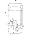
図1に示すように、第1の実施形態に係る操舵支援装置10は、車両500に搭載されて用いられる。操舵支援装置10は、制御装置100、操舵角および操舵トルクを検出する回転角トルクセンサ20、回転角センサ21、前方カメラ22、車室内カメラ23、ミリ波レーダ24、車輪速度センサ25、GPS26、操舵駆動装置31および転舵駆動装置32を備えている。車両500は、前側車輪501、操舵入力装置としてのステアリングホイール41、転舵装置42を含む操舵機構40、フロントガラス510およびフロントバンパ520を備えている。なお、車両は500、対象物を検出する検出部として、少なくとも、ミリ波レーダ24を備えていれば良く、ミリ波レーダ24と共に、前方カメラ22、および、ライダー(LIDAR:レーザレーダ)の少なくともいずれか1つが備えられていても良い。あるいは、ミリ波レーダ24に代えてステレオカメラが備えられていてもよく、またはミリ波レーダ24と共にステレオカメラが備えられていても良い。
First Embodiment:
As shown in FIG. 1, the
図2に示すように、車両500において、操舵機構40は、運転者の操舵操作を入力する操舵入力装置としてのステアリングホイール41、前側車輪501の転舵角を変化させる転舵装置42、上側ステアリングシャフト43aおよび下側ステアリングシャフト43b、および転舵装置42と前側車輪501とを接続する転舵軸44を備えている。なお、転舵される車輪は後側車輪であっても良い。操舵入力装置として回転操作されるステアリングホイール41に代えて、直線操作されるスティック状の操舵入力装置、すなわち、ステアリングスティックが用いられても良い。ステアリングスティックは、例えば、中立位置を中点に有する直線上を往復動され、直線上の操作位置が操舵角θsに相当する。直線上の操作位置である操舵位置は操舵角θsに変換され、各処理に用いられる。したがって、操舵入力装置の操舵角は操舵位置をも含む概念であり、操舵位置の変化量と、操舵角の変化量との間にはステアリングホイール41の場合と同様の関係が成立する。
As shown in FIG. 2, in the
第1の実施形態においては、いわゆるステアバイワイヤ方式の操舵機構40が用いられており、上側ステアリングシャフト43aおよび下側ステアリングシャフト43bは機械的に接続されていない。上側ステアリングシャフト43aの先端には反力を与えるための操舵側モータを含む操舵駆動装置31が接続され、上側ステアリングシャフト43aの中間位置には回転角トルクセンサ20が配置されている。下側ステアリングシャフト43bの先端には転舵装置42が接続され、下側ステアリングシャフト43bの基端あるいは中間には転舵角、すなわち前側車輪の舵角を検出するための回転角センサ21が配置されている。転舵装置42、より具体的には、転舵軸44には転舵側モータを含む転舵駆動装置32が配置されている。
In the first embodiment, a so-called steer-by-wire
操舵駆動装置31は、図示しないモータとモータ制御部とを備え、モータの出力軸の先端は上側ステアリングシャフト43aと直接または減速機構を介して接続されている。モータは、例えば、ブラシレスのDCモータであり、前側車輪と路面との間の摩擦抵抗を実現する反力トルクを発生させるために備えられており、ステアリングホイール41を介して、例えば、車速に応じた反力トルクを運転者に提供する。モータはまた、自動操舵モード時において、転舵角に応じたステアリングホイール41の操舵位置を実現するために備えられている。
The
転舵駆動装置32は、図示しないモータ、例えば、ブラシレスのDCモータとモータ制御部とを備え、モータの出力軸の先端にはピニオンギヤおよび必要に応じて減速機構が装着されている。転舵駆動装置32のピニオンギヤもまた、転舵軸44に備えられているラックギヤに噛み合わされており、モータのトルクによって転舵軸44が駆動される。したがって、転舵駆動装置32は、転舵装置42を駆動する転舵装置駆動部に相当し、ステアリングホイール41から入力される運転者による操舵力によることなく、転舵軸44を介して転舵装置42を駆動し、所望の前側車輪501の転舵を実現することができる。なお、転舵駆動装置32は、転舵軸44と同軸上にモータが配置される構成、下側ステアリングシャフト43bと同軸上にモータが配置される構成、を備えても良く、転舵装置42と一体に備えられていても良い。
The
転舵装置42は、例えば、下側ステアリングシャフト43bの先端に備えられているピニオンギヤと、転舵軸44に備えられているラックギヤとから構成されるラックアンドピニオンギア方式の転舵装置42である。ピニオンアンドピニオンギヤ機構によって、ステアリングシャフト43bの回転運動が転舵軸44の軸方向への運動、すなわち直線運動に変換され、転舵軸44が軸方向に駆動されることによって前側車輪501が所望の転舵角に転舵される。なお、転舵装置42は他の機構、例えば、ボールナット式によって実現されても良い。
The steering device 42 is, for example, a rack and pinion gear type steering device 42 composed of a pinion gear provided at the tip of the
ステアバイワイヤ方式の操舵機構40においては、操舵駆動装置31および転舵駆動装置32によって舵角可変機能が実現される。具体的には、操舵角θsと転舵角θwとの間には、操舵駆動装置31および転舵駆動装置32によって実現される可変の差動角θg=(θw−θs)がもたらされる。手動操舵モード時には、回転角トルクセンサ20によってステアリングホイール41を介して運転者に対して反力トルクが提供される。また、回転角トルクセンサ20によって検出されたステアリングホイール41の操舵角および決定された差動角に応じて制御装置100によって転舵角が決定され、転舵駆動装置32の転舵側モータが制御され、転舵装置42が駆動される。すなわち、転舵装置42は、ステアリングホイール41を介して操舵角θsが入力されると、操舵角θsに差動角θgを加えた転舵角θwで作動する。自動操舵モード時には、決定された転舵角θwを実現するよう転舵駆動装置32の転舵側モータが制御され、転舵装置42が駆動される。ステアリングホイール41は、回転角センサ21によって検出された転舵角θwを用いて、決定された差動角θgを実現する操舵角θsを採るように操舵駆動装置31の操舵側モータによって駆動される。すなわち、ステアリングホイール41は、転舵装置42が転舵角θwを取ると、転舵角θwから差動角θgを減じた操舵角θsで作動する。
In the
ステアバイワイヤ方式においては、操舵駆動装置31と転舵駆動装置32とはそれぞれモータを備え、独立して動作可能であるから、上側ステアリングシャフト43aと下側ステアリングシャフト43bとの間の相対角は可変となり、ステアリングホイール41の操舵角と転舵装置42の転舵角との間の差動角θgも連続的に可変とされる。
In the steer-by-wire system, the
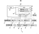
制御装置100は、図3に示すように、中央処理装置(CPU)101、メモリ102、入出力インタフェース103およびバス104を備えている。CPU101、メモリ102および入出力インタフェース103はバスを介して双方向通信可能に接続されている。メモリ102は、操舵支援プログラムP1、および伝達比設定プログラムP2を不揮発的且つ読み出し専用に格納するメモリ、例えばROMと、CPU101による読み書きが可能なメモリ、例えばRAMとを含んでいる。メモリ102には、ナビゲーション用の地図データを格納するメモリも含まれている。操舵支援プログラムP1は、車両の走行状態または走路情報の少なくともいずれか一方に基づいて転舵装置42によって実現されるべき転舵角θw、すなわち、目標転舵角θw*を決定し、転舵駆動装置32を制御する自動操舵モードを実行するためのプログラムである。伝達比設定プログラムP2は、運転者の身体姿勢に応じて操舵角θsの変化量に対する転舵角θwの変化量の比である伝達比αを設定する。より具体的には、伝達比設定プログラムP2は、運転者の身体の一部とステアリングホイール41との距離を身体姿勢に応じたパラメータとして採用し、距離が小さくなるにつれて、伝達比αを大きな値に設定する。ステアリングホイール41との距離が用いられる場合には、ステアリングホイール41は運転者側に移動しないので、運転者の身体姿勢は専らステアリングホイール41に対する運転者の身体位置であるということができる。なお、伝達比αは離散的に設定されても良く、あるいは連続的に設定されても良い。
As shown in FIG. 3, the
CPU101は、操舵支援プログラムP1を実行することによって、自動操舵モードを実行する操舵制御部として機能し、また、伝達比設定プログラムP2を実行することによって、自動操舵モード時に運転者の身体姿勢に応じて伝達比を設定する伝達比設定部として機能する。なお、自動操舵モードを実行する操舵制御部には、CPU101に加えて、CPU101からの制御信号を受けて転舵装置42の転舵角を制御する転舵駆動装置32が含まれても良い。本実施形態において、転舵駆動装置32は、自動操舵モード実行時に、転舵装置42を駆動して目標転舵角θw*を実現するためのアクチュエータとしての転舵装置駆動部である。CPU101は、単体のCPUであっても良く、各プログラムを実行する複数のCPUであっても良く、あるいは、複数のプログラムを同時実行可能なマルチスレッドタイプのCPUであっても良い。
The
入出力インタフェース103には、回転角トルクセンサ20、回転角センサ21、前方カメラ22、車室内カメラ23、ミリ波レーダ24、車輪速度センサ25、GPS26、操舵駆動装置31、転舵駆動装置32および報知部50がそれぞれ制御信号線を介して接続されている。回転角トルクセンサ20、回転角センサ21、前方カメラ22、車室内カメラ23、ミリ波レーダ24、車輪速度センサ25およびGPS26からは、検出情報が入力され、操舵駆動装置31および転舵駆動装置32に対しては目標操舵角および目標転舵角を指示する制御信号が出力され、報知部50に対しては報知を指示する制御信号が出力される。
The input /
回転角トルクセンサ20は、ステアリングホイール41の操舵位置、すなわち、回転角を上側ステアリングシャフト43aの回転角として検出し、ステアリングホイール41を介して上側ステアリングシャフト43aに加えられるトルクを検出するためセンサである。回転角トルクセンサ20は、例えば、直進時のステアリングホイール41の操舵角を0°とし、右回転を正値として出力し、左回転を負値として出力しても良く、あるいは、360°の絶対角度と回転数とを用いて操舵角を正値にて出力しても良い。また、回転角トルクセンサ20は、図示しない2分割された上側ステアリングシャフト43aを連結するトーションバーに発生する捻れに伴い検出される位相差を変換することにより操舵力である操舵トルクを検出する。検出される操舵トルクは、例えば、直進時のステアリングホイール41の操舵角を基準として右旋回は正値、左旋回は負値といった値を取る。回転角トルクセンサ20としては、例えば、磁気式のセンサが用いられ得る。なお、回転角センサとトルクセンサとは別体であっても良い。
The rotation
回転角センサ21は、下側ステアリングシャフト43bの回転角を検出することにより、転舵駆動装置32によって転舵される転舵装置42、すなわち、前側車輪501の転舵角θwを検出するためのセンサである。なお、回転角センサ21は、転舵駆動装置32が備えるモータの回転角を検出する回転角センサであっても良い。回転角センサ21は、例えば、転舵装置42の転舵角を0°とし、右回転を正値として出力し、左回転を負値として出力しても良く、あるいは、360°の絶対角度と回転数とを用いて操舵角を正値にて出力しても良い。
The
前方カメラ22は、CCD等の撮像素子を1つ備える撮像装置であり、可視光を受光することによって対象物の外形情報を検知結果である画像データとして出力するセンサである。前方カメラ22から出力される画像データは、時系列的に連続する複数のフレーム画像によって構成されており、各フレーム画像は画素データにより表されている。本実施形態において、前方カメラ22はフロントガラス510の上部中央に配置されている。前方カメラ22から出力される画像データは、モノクロの画像データまたはカラーの画像データである。前方カメラ22には、単眼カメラまたは複眼のステレオカメラが用いられ得る。
The
車室内カメラ23は、例えば、ルームミラーの運転席側、運転席側フロントガラスの上端、計器盤内、ステアリングコラム上といった、少なくとも運転者の上半身を撮像可能な場所に配置されている。車室内カメラ23は、前方カメラ22と同様の構成を備えるステレオカメラである。あるいは、深度センサが別途備えられる場合には、単眼の車室内カメラ23が用いられても良い。また、車室内カメラ23は、遠赤外光を運転者に対して照射して遠赤外光を受光する撮像装置であっても良い。車室内カメラ23は、車両の車室内に存在する運転者の身体姿勢、例えば、上半身の姿勢、腕の位置、頭部の位置、頭部の角度、まぶたの状態、視線移動を検出するために用いられる。なお、本実施形態において、身体姿勢には、少なくとも、運転者の上半身の左右、前後への傾き、運転者の運転席への着席の有無、腕の位置、指先の位置、頭部の位置・前後左右の角度、まぶたの開閉、視線位置が含まれる。
The
ミリ波レーダ24はミリ波を射出し、対象物によって反射された反射波を受信することによって対象物の位置および距離を検出するためのセンサである。本実施形態において、ミリ波レーダ24は、フロントバンパ520の中央に配置されているが、フロントバンパ520の全面に複数、または、フロントバンパ520の両側面に配置されていても良い。ミリ波レーダ24から出力される検出信号は、例えば、ミリ波レーダ24が備える処理回路において受信波が処理された対象物の代表位置を示す点列からなる信号であっても良く、あるいは、未処理の受信波を示す信号であっても良い。未処理の受信波が検出信号として用いられる場合には、制御装置100において対象物の位置および距離を特定するための信号処理が実行される。なお、ミリ波レーダに代えて、ライダーが用いられても良い。
The
車輪速度センサ25は、前側車輪501の回転速度を検出するセンサであり、各前側車輪501に備えられている。車輪速度センサ25から出力される検出信号は、車輪速度に比例する電圧値または車輪速度に応じた間隔を示すパルス波である。車輪速度センサ25からの検出信号を用いることによって、車両速度、車両の走行距離等の情報を得ることができる。
The
GPS(全地球測位システム)26は、GPS衛星からの信号を受信する受信機および受信信号を用いて受信機の位置を決定する制御部を含む、車両の位置(緯度、経度)を特定するためのシステムである。制御装置100は、GPS26により得られた自車位置および、GPS26により得られた自車位置を地図データにマッピングした地図情報60を用いて走路情報を決定することができる。なお、走路情報には、このほかにも、例えば、他車両との間の通信によって得られる他車両の走行状態および渋滞・道路の情報、交通情報インフラストラクチャによって得られる交通情報が含まれる。
The GPS (Global Positioning System) 26 identifies the position (latitude, longitude) of a vehicle, including a receiver that receives signals from GPS satellites and a control unit that determines the position of the receiver using the received signals. System. The
図2に示すように、制御装置100は、CPU101が各種プログラムを実行することによって、伝達比演算部M1、目標差動角演算部M2および目標転舵角演算部M3の機能部を実現する。伝達比演算部M1は、CPU101が伝達比設定プログラムP2を実行することによって実現される。伝達比演算部M1は、操舵モードが自動操舵モードであるか手動操舵モードであるかに応じて、操舵角の変化量(Δθs)に対する転舵角の変化量(Δθw)の比である伝達比α=Δθw/Δθsを決定、設定する。伝達比αは、自動操舵モード時における自動操舵伝達比αautoおよび手動操舵モード時における手動操舵伝達比αmanが予め設定されており、自動操舵モード時における伝達比αautoは、一般的に、自動操舵モード実行時におけるステアリングホイール41の動きを抑制するために手動操舵モード時の伝達比αmanよりも大きな値に設定されている。本実施形態においては、伝達比演算部M1はさらに、自動操舵モード時における伝達比αautoを運転者の身体姿勢に応じて設定、すなわち、変更する。
As shown in FIG. 2, the
目標差動角演算部M2は、伝達比αを用いて操舵駆動装置31によって実現されるべき差動角である目標差動角θg*を算出する。目標差動角演算部M2は、伝達比演算部M1によって設定された伝達比αを用いて、自動操舵モード時の式(1)または手動操舵モード時の式(2)のいずれかの式に従い目標差動角θg*を算出する。
θg*=(1−1/α)θw 式(1)
θg*=(α−1)θs 式(2)
なお、ステアリングバイワイヤ方式が採用される本実施形態においては、目標差動角を算出することなく、自動操舵モード時には式(3)により目標操舵角θs*を、手動操舵モード時には式(4)により目標転舵角θw*が直接算出されても良い。この場合、目標差動角演算部M2は、目標操舵角演算部とされても良い。
θs*=θw/α 式(3)
θw*=αθs 式(4)
The target differential angle calculation unit M2 calculates the target differential angle θg * , which is the differential angle to be realized by the
θg * = (1-1 / α) θw equation (1)
θg * = (α-1) θs equation (2)
In the present embodiment in which the steering-by-wire method is adopted, the target steering angle θs * is calculated by the equation (3) in the automatic steering mode, and the equation (4) is used in the manual steering mode without calculating the target differential angle. The target steering angle θw * may be calculated directly. In this case, the target differential angle calculation unit M2 may be the target steering angle calculation unit.
θs * = θw / α equation (3)
θw * = αθs equation (4)
目標差動角演算部M2は、自動操舵モード時には、算出された目標差動角θg*を操舵駆動装置31に送信し、手動操舵モード時には、算出された目標差動角θg*を目標転舵角演算部M3に送信する。操舵駆動装置31では、制御部が受信した目標差動角θg*および目標転舵角演算部M3から受信した目標転舵角θw*を用いて式(3)から目標操舵角θs*を算出し、モータトルク指令値に変換し、モータを制御して目標操舵角θs*を実現する。なお、目標操舵角θs*に代えて目標操舵角変化量Δθs*を求め、モータを制御しても良い。この場合には、起点となる角度θsを目標操舵角変化量Δθs*に加算することによって、モータに送信すべき指令値を算出することができる。また、運転者によって視覚的に看取されるステアリングホイール41の動きは変化量であるが、モータに対するモータトルク指令値は、目標操舵角θs*を実現する指令値である。
Target differential angle calculating section M2 is the automatic steering mode, and sends the calculated target differential angle [theta] g * the
目標転舵角演算部M3は、CPU101が操舵制御プログラムP1を実行することによって実現される自動操舵モード時における目標転舵角を演算するための機能部である。目標転舵角演算部M3は、前方カメラ22からの映像信号、ミリ波レーダ24からの検出結果信号を含む走行状態、および地図情報60を含む走路情報を用いて転舵駆動装置32によって実現されるべき転舵角である目標転舵角θw*を算出する。目標転舵角θw*は、運転者によるステアリングホイール41を介した操舵角の入力に従属せず、自車両の速度、前方および側方の他車両、その他の進路上の障害物といった走行状態、直進およびカーブ、車線減少・増大、坂路といった走路の形状を含む走路情報に基づいて決定される転舵装置42の転舵角θwである。目標転舵角θw*は、目標転舵角演算部M3から転舵駆動装置32のモータ制御部に送信される。転舵駆動装置32では、モータ制御部が受信した目標転舵角θw*を実現するモータトルク指令値に変換し、モータを制御して目標転舵角θw*を実現する。
The target steering angle calculation unit M3 is a functional unit for calculating the target steering angle in the automatic steering mode realized by the
手動操舵モード時には、目標転舵角演算部M3は、目標差動角演算部M2から受信した目標差動角θg*および回転角トルクセンサ20から受信した操舵角θsを用いて式(2)から目標転舵角θw*を算出し、転舵駆動装置32のモータ制御部に送信する。なお、目標転舵角θw*に代えて目標転舵角変化量Δθw*を求め、モータを制御しても良い。この場合には、起点となる角度θwを目標転舵角変化量Δθw*に加算することによって、モータに送信すべき指令値を算出することができる。
In the manual steering mode, the target steering angle calculation unit M3 uses the target differential angle θg * received from the target differential angle calculation unit M2 and the steering angle θs received from the rotation
自動操舵モードは、CPU101が操舵支援プログラムP1を実行することによって実現される。なお、本実施形態における自動操舵モードは、運転者によるステアリングホイール41の保持を要求しないレベル3以上の自動操舵モードである。CPU101は、前方カメラ22およびミリ波レーダ24に基づき求められた自車両の状態および他車両の状態を含む走行状態および地図情報60を含む走路情報に基づいて自車両が進行する走行軌跡を決定し、車輪速度センサ25によって得られる自車速度、GPS26を用いて自車位置がマッピングされた地図情報60に基づいて、前側車輪501を転舵すべき転舵角である目標転舵角θw*を逐次決定し、転舵駆動装置32に送信する。転舵駆動装置32のモータ制御部は、受信した目標転舵角θw*に応じたトルク指令値、例えば、印加電圧をモータに印加して目標転舵角θw*を実現する。なお、自動操舵モードは、走行状態および走路情報の他に、予めプログラミングされた経路情報、道路に沿って設置された誘導情報、例えば、ビーコン等を提供する誘導情報提供設備からの情報が用いられても良い。
The automatic steering mode is realized by the
自動操舵モード実行時には、転舵装置42の作動に伴いステアリングホイール41の操舵角が変化する。具体的には、ステアリングホイール41は、伝達比αautoによって決定された目標差動角θg*と転舵駆動装置32における目標転舵角θw*、すなわち、自動操舵モード実行時には転舵装置42の転舵角θwと同義とに基づいて決定される目標操舵角θs*に応じて作動する。運転者が視認する具体的なステアリングホイール41の動きは、操舵角変化量Δθsであるから、操舵角変化量Δθs=差動角変化量Δθg−転舵角変化量θwであり、差動角変化量Δθg=(1−1/αauto)Δθwである。
When the automatic steering mode is executed, the steering angle of the
自動操舵モードは、例えば、操舵のみを走行状態および走路情報の少なくともいずれか一方に基づいて支援する態様、操舵に加えて自車を加速させる走行支援および制動支援を含む、いわゆる自動運転の態様のいずれかにおいて実行され得る。自動操舵モードは、一般道路および高速道路における車両走行時のみならず、車両を駐車場に駐車させ、あるいは、駐車場から発進する際においても実行され得る。また、自動操舵モードは、自動操舵モードをオン・オフするスイッチがオフされるまで、あるいは、自動運転をオン・オフするメインスイッチがオフされるまで継続される。したがって、運転者による操舵介入後、所定期間に亘って操舵介入が検知されないと、手動操舵モードの優先処理が終了され、自動操舵モードによる操舵モードが再び実行され、あるいは、一時的に中断されていた自動操舵モードが再開される。 The automatic steering mode is, for example, a mode of so-called automatic driving, which includes a mode in which only steering is supported based on at least one of a running state and a running road information, and a running support and a braking support for accelerating the own vehicle in addition to steering. Can be performed in either. The automatic steering mode can be executed not only when the vehicle is running on a general road and a highway, but also when the vehicle is parked in a parking lot or when the vehicle is started from the parking lot. Further, the automatic steering mode is continued until the switch for turning on / off the automatic steering mode is turned off or the main switch for turning on / off the automatic operation is turned off. Therefore, if the steering intervention is not detected for a predetermined period after the steering intervention by the driver, the priority processing of the manual steering mode is terminated, and the steering mode by the automatic steering mode is executed again or temporarily interrupted. The automatic steering mode is restarted.
図4および図5を参照して第1の実施形態に係る操舵支援装置10によって実行される、伝達比設定処理について説明する。図4に示す処理ルーチンは、CPU101が伝達比設定プログラムP2を実行することによって実行される。なお、図4に示す処理ルーチンは、CPU101が操舵支援プログラムP1を実行中し、自動操舵モードがオンされた後に、自動操舵モードのスイッチがオフされるまで所定のタイミングで繰り返し実行される。
The transmission ratio setting process executed by the
CPU101は、運転者の身体姿勢を取得する(ステップS100)。本実施形態では、運転者の身体の一部として手先に注目する。身体姿勢の取得は、例えば以下のように行われる。CPU101は、車室内カメラ23によって撮像された運転者の画像データを用いて運転者の上半身の骨格構造および骨格構造の3次元空間上における位置を特定する。骨格構造は、画像データに対して画像処理、例えば、特徴点の抽出処理を行って、運転者の頭部、左右の肩、左右の肘、左右の手首、左右の手先に相当する特徴点の3次元空間上における位置、すなわち、(x、y、z)座標を特定し、これら特定した位置を用いて3次元リンク機構を構築することによって取得することができる。得られた骨格構造と所望のタイミングで取得された画像データとを用いて、各特徴点の3次元空間上における経時的な変化、すなわち移動を監視または特定することによって、所望のタイミングにおける運転者の身体姿勢が取得され、手先位置が特定される。このように、マーカを用いることなく身体姿勢を取得または推定する技術は、マーカレスモーションキャプチャ技術として知られており、例えば、マイクロソフト社のKinectを用いても実現できる。なお、図5に示すように、x軸、y軸を水平方向(車幅方向)および垂直方向(車高方向)の軸とし、z軸を奥行き方向(車長方向)の軸とする場合に、z座標は、ステレオカメラが用いられる場合には三角測量法により、深度センサが用いられる場合には検出された深度によって決定される。
The
運転者の手先位置の取得は、この他に、骨格構造を構築することなく、あるいは、骨格構造を構築した上で、手先位置に相当する特徴点の座標位置を追跡することによって行われても良く、あるいは、車室内カメラ23に代えて、ステアリングホイール41から運転席方向、すなわち、運転者方向、図5中のZ方向に、例えば、2つの予め定められた距離に光線の遮蔽を検出する光センサ、例えば赤外線センサをそれぞれ配置しておき、2つの予め定められた距離における光線の遮蔽の組み合わせを用いて行われても良い。
In addition to this, the acquisition of the driver's hand position may be performed without constructing the skeletal structure or by tracking the coordinate position of the feature point corresponding to the hand position after constructing the skeletal structure. Well, or instead of the
CPU101は、取得した身体姿勢を用いて、ステアリングホイール41と手先BDの距離Dが予め定められた第1の判定閾値a1未満であるか否かを判定する(ステップS110)。すなわち、ステアリングホイール41と手先BDとの物理的な位置関係に応じて伝達比αを設定する。距離Dは、例えば、ステアリングホイール41のハブ412の表面、すなわち中央部表面を起点とする距離であり、あるいは、リム411のうち運転席側に最も近い位置を起点とする距離である。距離Dは、例えば、起点座標から手先BDに対応する座標との間のユークリッド距離を算出することによって取得される。第1の判定閾値a1は、ステアリングホイール41と手先BDとが接触、または接触している可能性がある距離であり、本実施形態においては、マージンを考慮して0よりも大きな値が採用されている。また、ステアリングホイール41のハブ412の表面からの距離が距離Dとして用いられる場合には、運転者により近いリム411とハブ412の表面との距離差がa1として用いられ得る。この他にも、ステップS110における判定は、距離D=0または距離D<0であるか否かによって実行されても良い。
The
CPU101は、D<a1であると判定した場合には(ステップS110:Yes)、伝達比α=∞に設定し(ステップS120)、ステップS160に移行する。すなわち、運転者の手先BDとステアリングホイール41とが接触または接触している可能性があるので、転舵装置42による前側車輪501の転舵動作にステアリングホイール41の操舵回転を連動させない。すなわち、ステアリングホイール41を作動させない。この結果、自動操舵モード時におけるステアリングホイール41の回転動作に伴う、不測のステアリングホイール41と手先BDとの接触または干渉を抑制または防止することができる。なお、この場合におけるステアリングホイール41と手先との接触とは、静止した状態のステアリングホイール41と手先BDとの接触でなく、回動するステアリングホイール41と手先BDとの接触を意味する。また、ステアリングホイール41と手先BDとの干渉の一例として、回動するステアリングホイール41の部位、例えば、ステアリングホイール41のハブ412とリム411とを接続するスポーク413が手先と当たること、手先を巻き込むことが含まれる。ステアリングホイール41と転舵装置42との連動を遮断することによって、ステアリングホイール41と運転者との接触に伴う転舵干渉が防止される。
When the
CPU101は、D<a1でないと判定した場合には(ステップS110:No)、ステアリングホイール41と手先BDとの距離Dが第1の判定閾値a1以上かつ予め定められた第2の判定閾値a2未満であるか否かを判定する(ステップS130)。第2の判定閾値a2は、ステアリングホイール41と手先BDとが接触する可能性がある距離であり、第1の判定閾値a1よりも大きな値である。CPU101は、a1≦D<a2であると判定した場合には(ステップS130:Yes)、伝達比α=α1に設定し(ステップS140)、ステップS160に移行する。伝達比α1は、運転者がステアリングホイール41が回転しないことに違和感を感じることなく、また、無用なステアリングホイール41の動きを抑制可能な、ステアリングホイール41の操舵角変化量Δθsを実現することができる伝達比であり、例えば、1または1近傍の値が用いられる。
When the
CPU101は、a1≦D<a2でないと判定した場合には(ステップS130:No)、伝達比α=α2に設定し(ステップS150)、ステップS160に移行する。伝達比α2は自動操舵モード時に規定値として設定される伝達比αautoであり、伝達比α1よりも小さく、1よりも小さい値である。また、伝達比α2は、操舵角θsおよび操舵角変化量Δθsが転舵角θwおよび転舵角変化量Δθwよりも大きくなる伝達比である。したがって、転舵角変化量Δθwが小さい場合にも操舵角変化量Δθsを十分に取ることが可能となり、自動操舵モード時における運転者の違和感を低減または排除することができる伝達比である。なお、ステップS110およびS130の判定順序は逆であっても良い。
When the
CPU101は、設定された伝達比αを用いて既述の式(1)に基づき目標差動角θg*を算出し(ステップS160)、操舵駆動装置31に送信して本処理ルーチンを終了する。操舵駆動装置31は、既述の式(3)用いて目標操舵角θs*を算出し、ステアリングホイール41の操舵位置、すなわち、操舵角θsを設定する。
The
以上説明した第1の実施形態に係る操舵支援制御10によれば、自動操舵モード時における伝達比を運転者の身体姿勢に応じて設定することが可能となり、運転者の身体姿勢に応じた伝達比にてステアリングホイール41を作動させることができる。より具体的には、運転者の身体姿勢が、運転者の手先がステアリングホイール41と接触している、あるいは接触または干渉している可能性が有る身体姿勢である場合には、伝達比αを無限大に設定し、転舵装置42に連動して回転するステアリングホイール41、特にはスポーク413、リム411と運転者の身体の一部、特には手先BD、手首、腕との接触や干渉を防止または抑制することができる。ステアリングホイール41の回転速度が高い場合には、運転者の身体保護に更に有効である。加えて、ステアリングホイール41と運転者とが接触、干渉することに伴う車両挙動の乱れ、例えば、自動操舵時における衝突回避操舵の阻害や駐車の中断、を防止または抑制し、安定した車両500の走行軌跡を実現することができる。なお、伝達比αは無限大ではなく、例えば、転舵角変化量Δθwが35°の場合に操舵角変化量Δθsが0.5°となるような有限値であっても良い。
According to the
第1の実施形態に係る操舵支援装置10によれば、運転者の身体姿勢が、運転者の手先BDがステアリングホイール41と接触または干渉する可能性が有る身体姿勢である場合には、伝達比αを自動操舵モード時の規定の伝達比αautoよりも大きなα1に設定する。したがって、運転者はステアリングホイール41の回転動作を視認可能となり、自動操舵モードによる車両500の旋回動作に関する違和感の低減または排除が可能となり、また、無用なステアリングホイール41の動きを抑制することにより、運転者の身体保護を図ることができる。なお、第1の実施形態においては伝達比αを設定すると表現しているが、自動操舵モード時における伝達比autoを運転者の身体姿勢に応じて変更するということもでき。
According to the
第2の実施形態:
第1の実施形態においては、ステアリングホイール41と運転者の手先BDとの距離を身体姿勢に応じたパラメータとして採用し、ステアリングホイール41と運転者の身体の一部との接触の有無や可能性を指標として伝達比αを設定していた。これに対して、第2の実施形態においては、三次元空間における特定の領域を注意領域として規定し、当該注意領域と手先との間の最小のユークリッド距離をD1として、D1が小さくなるに連れて伝達比αを大きく設定しても良い。すなわち、運転者の身体の一部とステアリングホイール41との距離に加え、ステアリングホイール41の回転動作を身体姿勢に応じたパラメータとして採用しても良い。なお、操舵支援装置10の構成自体は第1の実施形態に係る操舵支援装置と同様であるから操舵支援装置10の構成の説明は同一の符号を付すことで省略する。
Second embodiment:
In the first embodiment, the distance between the
注意領域としては、図6に示すようにステアリングホイール41の空間部分、すなわち、リム411、スポーク413およびハブ412とによって区画形成される空間A1〜A3が用いられる。注意領域は、予め(x、y、z)座標によって規定することが可能であり、スポーク413の座標位置は、車室内カメラ23によって得られる画像および回転角トルクセンサ20によって得られる回転角によって特定可能である。運転者の身体の一部、典型的には手先BDの位置(座標)は、車室内カメラ23によって得られる画像から特定可能である。したがって、スポーク413の内、手先BDに最も近い部位と手先BDとのユークリッド距離が最小のユークリッド距離D1とされる。なお、ステアリングホイール41は連続的に回転しユークリッド距離D1も連続的に変化するので、伝達比αは離散的に複数の値に設定されてもよく、あるいは、ユークリッド距離D1に比例して連続的な値に設定されても良い。
As the attention area, as shown in FIG. 6, the space portion of the
第2の実施形態によれば、自動操舵モード時にステアリングホイール41が急回転する際に、手先BDとスポーク413との衝突を防止または衝突に伴うダメージを低減することが可能となり、運転者の保護と、車両挙動の乱れの防止または抑制の双方を実現することができる。
According to the second embodiment, when the
第3の実施形態:
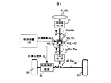
第1および第2の実施形態に係る操舵支援装置は、ステアバイワイヤ方式の操舵機構40を備えているが、図7に示すように、ステアリングホイール41と転舵装置42とが舵角可変装置70を介して機械的に接続されている操舵機構40aが用いられても良い。第3の実施形態に係る操舵支援装置は、操舵機構40aが異なり、操舵駆動装置31に代えて舵角可変装置70が備えられている点、転舵駆動装置32に代えて転舵補助装置72が備えられている点を除いて、第1および第2の実施形態に係る操舵支援装置10と同様の構成を備えているので、同一の構成には同一の符号を付してその説明を省略する。
Third embodiment:
The steering support device according to the first and second embodiments includes a
第3の実施形態において、ステアリングシャフトは、ステアリングホイール41と舵角可変装置70とを接続する上側ステアリングシャフト43aと舵角可変装置70と転舵装置42とを接続する下側ステアリングシャフト43bとの2つの部品により構成されている。
In the third embodiment, the steering shaft includes an
舵角可変装置70は、入力軸の回転角度と出力軸の回転角度との間に連続可変的に差動角を発生させる装置である。舵角可変装置70は、モータ70aと図示しないモータ制御部とを備えている。モータ70aは、例えば、ブラシレスのDCモータであり、ステータ70bが固定されているハウジングは上側ステアリングシャフト43aに接続され、モータ70aのロータ70cと同軸の出力軸は図示しない減速機構を介して下側ステアリングシャフト43bに接続されている。したがって、操舵角θsと転舵角θwとの間には、減速機構の減速比によって一義に決定される差動角θg=(θw−θs)がもたらされる。したがって、転舵装置42は、ステアリングホイール41を介して操舵角θsが入力されると、操舵角θsに差動角θgを加えた転舵角θwで作動する。舵角可変装置70は、モータ70aを備えているので、ハウジングと出力軸との間の相対角は可変となり、ステアリングホイール41の操舵角と転舵装置42の転舵角との間の差動角θgも連続的に可変とされる。舵角可変装置70では、モータ制御部が受信した目標差動角θg*を実現するモータトルク指令値に変換し、モータを制御して目標差動角θg*を実現する。したがって、自動操舵モード時には、転舵補助装置72を介して実現されている転舵装置42の転舵角θwと目標差動角θg*とによって定められる、操舵角θs=(θw−θg*)でステアリングホイール41を作動させることができる。なお、減速機構としては、遊星歯車機構や波動歯車機構が用いられ、モータ31aのトルクが十分に大きい場合には減速機構は備えられなくても良い。
The steering angle variable device 70 is a device that continuously and variably generates a differential angle between the rotation angle of the input shaft and the rotation angle of the output shaft. The steering angle variable device 70 includes a
転舵補助装置72は、図示しないモータとモータ制御部とを備え、モータの出力軸の先端にはピニオンギヤおよび必要に応じて減速機構が装着されている。転舵補助装置72のピニオンギヤもまた、転舵軸44に備えられているラックギヤに噛み合わされており、モータのトルクによって転舵軸44が駆動される。したがって、転舵補助装置72は、転舵装置42を駆動する転舵装置駆動部に相当し、ステアリングホイール41から入力される運転者による操舵力を要することなく、転舵軸44を介して転舵装置42を駆動し、所望の前側車輪501の転舵を実現することができる。なお、転舵補助装置72は、ステアリングホイール41から入力される操舵力を補助する操舵力補助装置としても用いられ得る。また、転舵補助装置72は、転舵軸44と同軸上にモータが配置される構成を備えていても良く、転舵装置42と一体に備えられていても良い。
The
回転角センサ71は、ステアリングホイール41の操舵位置、すなわち、回転角を上側ステアリングシャフト43aの回転角として検出するためセンサである。回転角センサ71は、例えば、直進時のステアリングホイール41の操舵角を0°とし、右回転を正値として出力し、左回転を負値として出力しても良く、あるいは、360°の絶対角度と回転数とを用いて操舵角を正値にて出力しても良い。
The
トルクセンサ73は、ステアリングホイール41を介して入力される操舵力として、下側ステアリングシャフト43bの回転トルクを検出するためのセンサである。トルクセンサ73は、図示しない2分割された下側ステアリングシャフト43bを連結するトーションバーに発生する捻れに伴い検出される位相差を変換することにより操舵力である操舵トルクを検出する。検出される操舵トルクは、例えば、直進時のステアリングホイール41の操舵角を基準として右旋回は正値、左旋回は負値といった値を取る。なお、トルクセンサ73には転舵角を検出するための回転角センサが一体に備えられていても良い。また、トルクセンサ73は上側ステアリングシャフト43aに備えられていても良い。
The torque sensor 73 is a sensor for detecting the rotational torque of the
以上説明した第3の実施形態に係る操舵支援制御10によっても、自動操舵モード時における伝達比を運転者の身体姿勢に応じて設定することができる。また、第3の実施形態に係る操舵支援制御10は、第1および第2の実施形態に係る操舵支援装置10によって得られる、より具体的な効果についても得ることができる。
The
その他の実施形態:
(1)第1および第2の実施形態においては、検出時におけるステアリングホイール41と運転者の手先と距離を姿勢状態として伝達比αが設定されているが、検出の後に予測される身体姿勢に応じて伝達比αが設定されても良い。より具体的には、運転者の手先とステアリングホイール41との接触可能性、運転者の手先が注意領域へ侵入する可能性をパラメータとして伝達比を設定しても良い。運転者の身体姿勢の予測は、運転者の骨格構造を構築し、手先に相当する部位および他の部位の経時的な移動特性、例えば、加速度、移動方向を用いて身体姿勢を推定することにより可能である。
Other embodiments:
(1) In the first and second embodiments, the transmission ratio α is set with the distance between the
(2)第1および第2の実施形態においては、ステアリングホイール41と運転者の手先との距離を身体姿勢に応じたパラメータとして採用しているが、運転者の身体姿勢のみに基づいて伝達比αが設定されても良い。自動操舵モード時には、運転者が本や、スマートフォンといった情報端末を利用することが考えられる。そこで、運転者が何か物体を保持したことが推定される場合には、伝達比αを大きくして、物体とステアリングホイール41との接触、あるいは、物体と回転するステアリングホイール41との接触を防止しても良い。
(2) In the first and second embodiments, the distance between the
(3)第1および第2の実施形態においては、ステアリングホイール41と運転者の手先との距離が予め定められた判定値よりも小さい場合に、伝達比αを設定しているが、伝達比αの設定前に報知部50によってステアリングホイール41との接触可能性を運転者に対して報知をしても良い。報知部50としては、例えば、スピーカ、計器盤上の表示部が用いられ、音声または画像・文字表示によって報知され得る。
(3) In the first and second embodiments, the transmission ratio α is set when the distance between the
(4)第1および第2の実施形態においては、CPU101が操舵支援プログラムP1および伝達比設定プログラムP2を実行することによって、ソフトウェア的に操舵制御部および目標差動角制御部が実現されているが、予めプログラムされた集積回路またはディスクリート回路によってハードウェア的に実現されても良い。
(4) In the first and second embodiments, the steering control unit and the target differential angle control unit are realized by software by executing the steering support program P1 and the transmission ratio setting program P2 by the
以上、実施形態、変形例に基づき本開示について説明してきたが、上記した発明の実施の形態は、本開示の理解を容易にするためのものであり、本開示を限定するものではない。本開示は、その趣旨並びに特許請求の範囲を逸脱することなく、変更、改良され得ると共に、本開示にはその等価物が含まれる。たとえば、発明の概要の欄に記載した各形態中の技術的特徴に対応する実施形態、変形例中の技術的特徴は、上述の課題の一部又は全部を解決するために、あるいは、上述の効果の一部又は全部を達成するために、適宜、差し替えや、組み合わせを行うことが可能である。また、その技術的特徴が本明細書中に必須なものとして説明されていなければ、適宜、削除することが可能である。例えば、上記第1の態様に係る車両の操舵支援装置を適用例1とし、
適用例2:適用例1に記載の車両の操舵支援装置において、
前記身体姿勢検出部は、前記運転者の身体の一部と前記操舵入力装置との物理的な位置関係を検出し、
前記伝達比設定手段は、検出された前記物理的な位置関係に応じて前記伝達比を設定する、車両の操舵支援装置。
適用例3:適用例2に記載の車両の操舵支援装置において、
前記伝達比設定部は、前記運転者の身体の一部が前記操舵入力装置と接触すると判定した場合に、前記伝達比を無限大に設定する、車両の操舵支援装置。
適用例4:適用例2または3に記載の車両の操舵支援装置において、
前記伝達比設定部は、前記運転者の身体の一部と前記操舵入力装置との距離が予め定められた判定値よりも小さい場合に、前記伝達比を大きな値に設定する、車両の操舵支援装置。
適用例5:適用例2から適用例4のいずれか一項に記載の車両の操舵支援装置はさらに、
前記運転者の身体の一部と前記操舵入力装置との距離が予め定められた判定値よりも小さい場合に、前記伝達比の設定前に報知を実行する報知部を備える、車両の操舵支援装置。
適用例6:適用例1から5のいずれか一項に記載の車両の操舵支援装置において、
前記身体姿勢検出部は、前記運転者を撮像する撮像装置である、車両の操舵支援装置。
適用例7:適用例1から6のいずれか一項に記載の車両の操舵支援装置はさらに、前記操舵角と前記転舵角との間に差動角を発生させる舵角可変装置を備え、前記操舵制御部はさらに、設定した前記伝達比を用いて前記舵角可変装置を制御する、車両の操舵支援装置。
適用例8:適用例1から6のいずれか一項に記載の車両の操舵支援装置はさらに、前記操舵入力装置を駆動する操舵駆動部を備え、
前記操舵入力装置と前記転舵装置とは機械的に接続されておらず、
前記操舵制御部はさらに、設定した前記伝達比を用いて前記操舵駆動部を制御する、車両の操舵支援装置。
Although the present disclosure has been described above based on the embodiments and modifications, the above-described embodiments of the invention are for facilitating the understanding of the present disclosure and do not limit the present disclosure. The present disclosure may be modified or improved without departing from its spirit and claims, and the present disclosure includes its equivalents. For example, the embodiments corresponding to the technical features in each of the embodiments described in the column of the outline of the invention, the technical features in the modifications are for solving some or all of the above-mentioned problems, or the above-mentioned It is possible to replace or combine them as appropriate to achieve some or all of the effects. Further, if the technical feature is not described as essential in the present specification, it can be appropriately deleted. For example, the vehicle steering support device according to the first aspect is set as Application Example 1.
Application Example 2: In the vehicle steering support device according to Application Example 1.
The body posture detecting unit detects the physical positional relationship between a part of the driver's body and the steering input device.
The transmission ratio setting means is a vehicle steering support device that sets the transmission ratio according to the detected physical positional relationship.
Application Example 3: In the vehicle steering support device according to Application Example 2.
The transmission ratio setting unit is a vehicle steering support device that sets the transmission ratio to infinity when it is determined that a part of the driver's body comes into contact with the steering input device.
Application Example 4: In the vehicle steering support device according to Application Example 2 or 3.
The transmission ratio setting unit sets the transmission ratio to a large value when the distance between a part of the driver's body and the steering input device is smaller than a predetermined determination value. apparatus.
Application Example 5: The vehicle steering support device according to any one of Application Examples 2 to 4 is further applied.
A vehicle steering support device including a notification unit that executes notification before setting the transmission ratio when the distance between a part of the driver's body and the steering input device is smaller than a predetermined determination value. ..
Application example 6: In the vehicle steering support device according to any one of application examples 1 to 5.
The body posture detection unit is a vehicle steering support device that is an image pickup device that images the driver.
Application Example 7: The vehicle steering support device according to any one of Application Examples 1 to 6 further includes a steering angle variable device that generates a differential angle between the steering angle and the steering angle. The steering control unit is a vehicle steering support device that further controls the steering angle variable device using the set transmission ratio.
Application Example 8: The vehicle steering support device according to any one of Application Examples 1 to 6 further includes a steering drive unit for driving the steering input device.
The steering input device and the steering device are not mechanically connected and are not mechanically connected.
The steering control unit is a vehicle steering support device that further controls the steering drive unit using the set transmission ratio.
10…操舵支援装置、20…回転角トルクセンサ、21…回転角センサ、22…前方カメラ、23…車室内カメラ、24…ミリ波レーダ、31…操舵駆動装置、32…転舵駆動装置、40…操舵機構、41…ステアリングホイール、42…転舵装置、43a…上側ステアリングシャフト、43b…下側ステアリングシャフト、44…転舵軸、M1…伝達比演算部、M2…目標差動角演算部、M3…目標転舵角演算部、100…制御装置、101…CPU、102…メモリ、500…車両、501…前側車輪 10 ... Steering support device, 20 ... Rotation angle torque sensor, 21 ... Rotation angle sensor, 22 ... Front camera, 23 ... Vehicle interior camera, 24 ... Millimeter wave radar, 31 ... Steering drive device, 32 ... Steering drive device, 40 ... Steering mechanism, 41 ... Steering wheel, 42 ... Steering device, 43a ... Upper steering shaft, 43b ... Lower steering shaft, 44 ... Steering shaft, M1 ... Transmission ratio calculation unit, M2 ... Target differential angle calculation unit, M3 ... Target steering angle calculation unit, 100 ... Control device, 101 ... CPU, 102 ... Memory, 500 ... Vehicle, 501 ... Front wheel
Claims (10)
前記車両の運転者の身体の一部と前記操舵入力装置との物理的な位置関係を前記運転者の身体姿勢として検出する身体姿勢検出部(23)と、
前記車両の走行状態または走路情報の少なくともいずれか一方に基づいて決定された転舵角を実現するように前記転舵装置の駆動を制御する自動操舵モードの実行中に、前記検出された身体姿勢に応じて、操舵角の変化量に対する転舵角の変化量の比である伝達比を設定する伝達比設定部(101、P2)であって、前記運転者の身体の一部が前記操舵入力装置と接触すると判定した場合に、前記伝達比を無限大に設定する伝達比設定部、とを備える、車両の操舵支援装置。 A steering support device (10) for a vehicle (500) having a steering input device (41) and a steering device (42).
Body attitude detection unit for detecting a physical positional relationship between the part and the steering input device driver's body as the body posture of the driver of the vehicle (23),
At least during execution of the automatic steering mode for controlling the driving of the turning device so as to realize a turning angle which is determined based on one of the traveling state or track information of the vehicle, the detected body A transmission ratio setting unit (101, P2) that sets a transmission ratio that is the ratio of the amount of change in the steering angle to the amount of change in the steering angle according to the posture, and a part of the driver's body is the steering. A vehicle steering support device including a transmission ratio setting unit that sets the transmission ratio to infinity when it is determined that the vehicle comes into contact with an input device .
前記車両の運転者の身体の一部と前記操舵入力装置との物理的な位置関係を前記運転者の身体姿勢として検出する身体姿勢検出部(23)と、
前記車両の走行状態または走路情報の少なくともいずれか一方に基づいて決定された転舵角を実現するように前記転舵装置の駆動を制御する自動操舵モードの実行中に、前記検出された身体姿勢に応じて、操舵角の変化量に対する転舵角の変化量の比である伝達比を設定する伝達比設定部(101、P2)であって、前記運転者の身体の一部と前記操舵入力装置との距離が予め定められた判定値よりも小さい場合に、前記伝達比を、前記距離が前記判定値よりも大きい場合の伝達比よりも大きな値に設定する伝達比設定部、とを備える、車両の操舵支援装置。 A steering support device (10) for a vehicle (500) having a steering input device (41) and a steering device (42).
A body posture detection unit (23) that detects the physical positional relationship between a part of the driver's body of the vehicle and the steering input device as the driver's body posture.
The detected body posture during execution of an automatic steering mode that controls the drive of the steering device to achieve a steering angle determined based on at least one of the vehicle's running state or track information. It is a transmission ratio setting unit (101, P2) that sets a transmission ratio that is a ratio of a change amount of a steering angle to a change amount of a steering angle according to the above, and is a part of the driver's body and the steering input. A transmission ratio setting unit that sets the transmission ratio to a value larger than the transmission ratio when the distance to the device is larger than the determination value when the distance to the device is smaller than a predetermined determination value. , Vehicle steering support device.
前記運転者の身体の一部と前記操舵入力装置との距離が予め定められた判定値よりも小さい場合に、前記伝達比の設定前に報知を実行する報知部(50)を備える、車両の操舵支援装置。 The vehicle steering assist device according to claim 1 or 2 further comprises.
A vehicle having a notification unit (50) that executes notification before setting the transmission ratio when the distance between a part of the driver's body and the steering input device is smaller than a predetermined determination value. Steering support device.
前記身体姿勢検出部は、前記運転者を撮像する撮像装置である、車両の操舵支援装置。 In the vehicle steering support device according to any one of claims 1 to 3 .
The body posture detection unit is a vehicle steering support device that is an image pickup device that images the driver.
前記自動操舵モードを実行する操舵制御部(101、P1)と、
前記操舵角と前記転舵角との間に差動角を発生させる舵角可変装置(70)とを備え、前記操舵制御部はさらに、設定した前記伝達比を用いて前記舵角可変装置を制御する、車両の操舵支援装置。 The vehicle steering support device according to any one of claims 1 to 4 is
Steering control units (101, P1) that execute the automatic steering mode,
A steering angle variable device (70) for generating a differential angle between the steering angle and the steering angle is provided, and the steering control unit further uses the set transmission ratio to provide the steering angle variable device. A vehicle steering support device to control.
前記自動操舵モードを実行する操舵制御部(101、P1)と、
前記操舵入力装置を駆動する操舵駆動部(31)とを備え、
前記操舵入力装置と前記転舵装置とは機械的に接続されておらず、
前記操舵制御部はさらに、設定した前記伝達比を用いて前記操舵駆動部を制御する、車両の操舵支援装置。 The vehicle steering support device according to any one of claims 1 to 4 is
Steering control units (101, P1) that execute the automatic steering mode,
A steering drive unit (31) for driving the steering input device is provided.
The steering input device and the steering device are not mechanically connected and are not mechanically connected.
The steering control unit is a vehicle steering support device that further controls the steering drive unit using the set transmission ratio.
前記車両の運転者の身体の一部と前記操舵入力装置との物理的な位置関係を前記運転者の身体姿勢として検出し、
前記車両の走行状態または走路情報の少なくともいずれか一方に基づいて決定された転舵角を実現するように前記転舵装置の駆動を制御する自動操舵モードの実行中に、前記検出された身体姿勢に応じて、操舵角の変化量に対する転舵角の変化量の比である伝達比を設定する際、前記運転者の身体の一部が前記操舵入力装置と接触すると判定した場合、前記伝達比を無限大に設定する、車両における操舵支援制御方法。 A steering support control method for a vehicle (500) having a steering input device (41) and a steering device (42).
Detecting a physical positional relationship between the part and the steering input device of the driver's body of the vehicle as the body posture of the front Kiun rolling person,
During execution of the automatic steering mode for controlling the driving of the turning device so as to realize the rotation steering angle determined based on at least one of the traveling state or track information of the vehicle, the detected body pose When setting the transmission ratio, which is the ratio of the change amount of the steering angle to the change amount of the steering angle, when it is determined that a part of the driver's body comes into contact with the steering input device, the transmission ratio Steering support control method in the vehicle that sets to infinity .
前記車両の運転者の身体の一部と前記操舵入力装置との物理的な位置関係を前記運転者の身体姿勢として検出し、 The physical positional relationship between a part of the body of the driver of the vehicle and the steering input device is detected as the body posture of the driver.
前記車両の走行状態または走路情報の少なくともいずれか一方に基づいて決定された転舵角を実現するように前記転舵装置の駆動を制御する自動操舵モードの実行中に、前記検出された身体姿勢に応じて、操舵角の変化量に対する転舵角の変化量の比である伝達比を設定する際、前記運転者の身体の一部と前記操舵入力装置との距離が予め定められた判定値よりも小さい場合、前記伝達比を、前記距離が前記判定値よりも大きい場合の伝達比よりも大きな値に設定する、車両における操舵支援制御方法。 The detected body posture during execution of an automatic steering mode that controls the drive of the steering device to achieve a steering angle determined based on either the traveling state of the vehicle or at least one of the track information. When setting the transmission ratio, which is the ratio of the amount of change in the steering angle to the amount of change in the steering angle, the distance between the part of the driver's body and the steering input device is a predetermined determination value. A steering support control method in a vehicle, in which the transmission ratio is set to a value larger than the transmission ratio when the distance is larger than the determination value.
前記車両の運転者の身体の一部と前記操舵入力装置との物理的な位置関係を前記運転者の身体姿勢として検出するための機能と、
前記車両の走行状態または走路情報の少なくともいずれか一方に基づいて決定された転舵角を実現するように前記転舵装置の駆動を制御する自動操舵モードの実行中に、前記検出された身体姿勢に応じて、操舵角の変化量に対する転舵角の変化量の比である伝達比を設定するための機能であって、前記運転者の身体の一部が前記操舵入力装置と接触すると判定した場合に、前記伝達比を無限大に設定するための機能とを、コンピュータによって実現させる、車両における操舵支援制御プログラム。 A steering support control program for a vehicle (500) having a steering input device (41) and a steering device (42).
A function for detecting a physical body pose of a positional relationship before Kiun rolling's part and the steering input device of the driver's body of the vehicle,
During execution of the automatic steering mode for controlling the driving of the turning device so as to realize the rotation steering angle determined based on at least one of the traveling state or track information of the vehicle, the detected body pose It is a function for setting a transmission ratio which is a ratio of a change amount of a steering angle to a change amount of a steering angle according to the above, and it is determined that a part of the driver's body comes into contact with the steering input device. In this case, a steering support control program in a vehicle that realizes a function for setting the transmission ratio to infinity by a computer.
前記車両の運転者の身体の一部と前記操舵入力装置との物理的な位置関係を前記運転者の身体姿勢として検出するための機能と、 A function for detecting the physical positional relationship between a part of the body of the driver of the vehicle and the steering input device as the body posture of the driver, and
前記車両の走行状態または走路情報の少なくともいずれか一方に基づいて決定された転舵角を実現するように前記転舵装置の駆動を制御する自動操舵モードの実行中に、前記検出された身体姿勢に応じて、操舵角の変化量に対する転舵角の変化量の比である伝達比を設定するための機能であって、前記運転者の身体の一部と前記操舵入力装置との距離が予め定められた判定値よりも小さい場合に、前記伝達比を、前記距離が前記判定値よりも大きい場合の伝達比よりも大きな値に設定するための機能とを、コンピュータによって実現させる、車両における操舵支援制御プログラム。 The detected body posture during execution of the automatic steering mode that controls the driving of the steering device so as to realize a steering angle determined based on at least one of the traveling state of the vehicle and the track information. It is a function for setting the transmission ratio which is the ratio of the change amount of the steering angle to the change amount of the steering angle according to the above, and the distance between the part of the driver's body and the steering input device is set in advance. Steering in a vehicle, in which a computer realizes a function for setting the transmission ratio to a value larger than the transmission ratio when the distance is larger than the determination value when the determination value is smaller than the predetermined determination value. Assistance control program.
Priority Applications (2)
| Application Number | Priority Date | Filing Date | Title |
|---|---|---|---|
| JP2017116784A JP6801593B2 (en) | 2017-06-14 | 2017-06-14 | Vehicle steering support device and steering support control method |
| US16/007,190 US10843726B2 (en) | 2017-06-14 | 2018-06-13 | Method and apparatus for assisting steering of vehicle |
Applications Claiming Priority (1)
| Application Number | Priority Date | Filing Date | Title |
|---|---|---|---|
| JP2017116784A JP6801593B2 (en) | 2017-06-14 | 2017-06-14 | Vehicle steering support device and steering support control method |
Publications (3)
| Publication Number | Publication Date |
|---|---|
| JP2019001273A JP2019001273A (en) | 2019-01-10 |
| JP2019001273A5 JP2019001273A5 (en) | 2019-12-26 |
| JP6801593B2 true JP6801593B2 (en) | 2020-12-16 |
Family
ID=64657060
Family Applications (1)
| Application Number | Title | Priority Date | Filing Date |
|---|---|---|---|
| JP2017116784A Active JP6801593B2 (en) | 2017-06-14 | 2017-06-14 | Vehicle steering support device and steering support control method |
Country Status (2)
| Country | Link |
|---|---|
| US (1) | US10843726B2 (en) |
| JP (1) | JP6801593B2 (en) |
Families Citing this family (8)
| Publication number | Priority date | Publication date | Assignee | Title |
|---|---|---|---|---|
| JP7197413B2 (en) * | 2019-03-25 | 2022-12-27 | トヨタ自動車株式会社 | steering control system |
| WO2021044566A1 (en) * | 2019-09-05 | 2021-03-11 | 三菱電機株式会社 | Physique determination device and physique determination method |
| JP7247849B2 (en) * | 2019-10-11 | 2023-03-29 | トヨタ自動車株式会社 | parking assist device |
| DE102020103150A1 (en) | 2020-02-07 | 2021-08-12 | Knorr-Bremse Systeme für Nutzfahrzeuge GmbH | Electromechanical dual-circuit steering for a commercial vehicle |
| US11465672B2 (en) * | 2020-04-21 | 2022-10-11 | Nsk Ltd. | Steering device |
| US11780489B2 (en) * | 2021-04-21 | 2023-10-10 | Nsk Ltd. | Turning angle detecting device and electric power steering device |
| CN114822169B (en) * | 2022-05-06 | 2023-06-09 | 辽宁科技大学 | Auxiliary driving exercise method and device for learner-driven vehicle |
| CN117549962B (en) * | 2024-01-11 | 2024-04-19 | 博世汽车转向系统(济南)有限公司 | Control method of electric power steering system and electric power steering system |
Family Cites Families (13)
| Publication number | Priority date | Publication date | Assignee | Title |
|---|---|---|---|---|
| JP3738673B2 (en) * | 2000-06-29 | 2006-01-25 | トヨタ自動車株式会社 | Automatic steering device for vehicles |
| US20080154464A1 (en) | 2006-12-26 | 2008-06-26 | Honda Motor Co., Ltd. | Automatic Parking control apparatus for vehicle |
| JP5358978B2 (en) * | 2008-03-05 | 2013-12-04 | 日産自動車株式会社 | Vehicle travel control apparatus and method |
| JP5803061B2 (en) | 2010-06-16 | 2015-11-04 | 日産自動車株式会社 | Collision avoidance support device |
| EP2700542B1 (en) | 2011-04-22 | 2018-05-30 | Panasonic Intellectual Property Management Co., Ltd. | Vehicular input device and vehicular input method |
| US9150238B2 (en) * | 2012-06-04 | 2015-10-06 | GM Global Technology Operations LLC | System and method for automatically adjusting a steering tilt position |
| JP5527382B2 (en) * | 2012-10-12 | 2014-06-18 | トヨタ自動車株式会社 | Driving support system and control device |
| JP2014196039A (en) * | 2013-03-29 | 2014-10-16 | 株式会社エクォス・リサーチ | Drive assist |
| GB2525840B (en) * | 2014-02-18 | 2016-09-07 | Jaguar Land Rover Ltd | Autonomous driving system and method for same |
| JP6318720B2 (en) * | 2014-03-10 | 2018-05-09 | 日産自動車株式会社 | Vehicle steering control device and vehicle steering control method |
| JP2017024520A (en) * | 2015-07-21 | 2017-02-02 | 株式会社デンソー | Steering control device |
| US10289113B2 (en) * | 2016-02-25 | 2019-05-14 | Ford Global Technologies, Llc | Autonomous occupant attention-based control |
| US10315691B2 (en) * | 2017-03-30 | 2019-06-11 | Ford Global Technologies, Llc | Methods and apparatus to correct clear vision errors in a vehicle steering system |
-
2017
- 2017-06-14 JP JP2017116784A patent/JP6801593B2/en active Active
-
2018
- 2018-06-13 US US16/007,190 patent/US10843726B2/en active Active
Also Published As
| Publication number | Publication date |
|---|---|
| US10843726B2 (en) | 2020-11-24 |
| US20180362073A1 (en) | 2018-12-20 |
| JP2019001273A (en) | 2019-01-10 |
Similar Documents
| Publication | Publication Date | Title |
|---|---|---|
| JP6801593B2 (en) | Vehicle steering support device and steering support control method | |
| JP6507626B2 (en) | Vehicle perimeter monitoring device | |
| JP7103753B2 (en) | Collision avoidance device | |
| JP6801565B2 (en) | Vehicle steering support device and steering support method | |
| JP6658978B2 (en) | Driving support vehicle position error correction method and position error correction device | |
| JP6784223B2 (en) | Vehicle steering support device and steering support control method | |
| JP6055528B1 (en) | Vehicle steering control device | |
| JP6639194B2 (en) | Information display device | |
| CN111252140B (en) | Steering determination device and automatic driving system | |
| JP6763327B2 (en) | Collision avoidance device | |
| JP6607826B2 (en) | Travel control device | |
| JP2007253745A (en) | Avoidance operation calculating device, avoidance controller, vehicle provided with each device, avoidance operation calculating method, and avoidance control method | |
| JP6961964B2 (en) | Collision avoidance device | |
| US10745046B2 (en) | Steering assist apparatus of vehicle and method for steering assist apparatus | |
| US11620834B2 (en) | Periphery monitoring device | |
| JP2007190977A (en) | Vehicle control device | |
| JP2017140857A (en) | Vehicle control system | |
| JP2019089522A (en) | Lane departure prevention control device for vehicle | |
| JP4962176B2 (en) | Traveling track display device | |
| WO2019187716A1 (en) | Parking assistance device | |
| JP2020032949A (en) | Automatic operation system | |
| JP6595647B2 (en) | Travel control device, vehicle, and travel control method | |
| JP7173371B2 (en) | Driving support device override determination method and driving support device | |
| JP7059525B2 (en) | Parking support method and parking support device | |
| CA3149075A1 (en) | Vehicle control method, vehicle control system, and vehicle |
Legal Events
| Date | Code | Title | Description |
|---|---|---|---|
| A521 | Request for written amendment filed |
Free format text: JAPANESE INTERMEDIATE CODE: A523 Effective date: 20191115 |
|
| A621 | Written request for application examination |
Free format text: JAPANESE INTERMEDIATE CODE: A621 Effective date: 20191115 |
|
| A977 | Report on retrieval |
Free format text: JAPANESE INTERMEDIATE CODE: A971007 Effective date: 20200722 |
|
| A131 | Notification of reasons for refusal |
Free format text: JAPANESE INTERMEDIATE CODE: A131 Effective date: 20200804 |
|
| A521 | Request for written amendment filed |
Free format text: JAPANESE INTERMEDIATE CODE: A523 Effective date: 20200929 |
|
| TRDD | Decision of grant or rejection written | ||
| A01 | Written decision to grant a patent or to grant a registration (utility model) |
Free format text: JAPANESE INTERMEDIATE CODE: A01 Effective date: 20201027 |
|
| A61 | First payment of annual fees (during grant procedure) |
Free format text: JAPANESE INTERMEDIATE CODE: A61 Effective date: 20201109 |
|
| R151 | Written notification of patent or utility model registration |
Ref document number: 6801593 Country of ref document: JP Free format text: JAPANESE INTERMEDIATE CODE: R151 |
|
| R250 | Receipt of annual fees |
Free format text: JAPANESE INTERMEDIATE CODE: R250 |