JP6800164B2 - Magnetic coil power method and equipment - Google Patents
Magnetic coil power method and equipment Download PDFInfo
- Publication number
- JP6800164B2 JP6800164B2 JP2017553350A JP2017553350A JP6800164B2 JP 6800164 B2 JP6800164 B2 JP 6800164B2 JP 2017553350 A JP2017553350 A JP 2017553350A JP 2017553350 A JP2017553350 A JP 2017553350A JP 6800164 B2 JP6800164 B2 JP 6800164B2
- Authority
- JP
- Japan
- Prior art keywords
- power
- voltage
- linear amplifier
- current
- amplifier
- Prior art date
- Legal status (The legal status is an assumption and is not a legal conclusion. Google has not performed a legal analysis and makes no representation as to the accuracy of the status listed.)
- Active
Links
- 238000000034 method Methods 0.000 title claims description 74
- 238000002595 magnetic resonance imaging Methods 0.000 claims description 135
- 238000001208 nuclear magnetic resonance pulse sequence Methods 0.000 claims description 93
- 230000007704 transition Effects 0.000 claims description 34
- 230000008859 change Effects 0.000 claims description 14
- 230000000630 rising effect Effects 0.000 claims description 12
- 230000001174 ascending effect Effects 0.000 claims description 6
- 238000003384 imaging method Methods 0.000 description 13
- 230000008569 process Effects 0.000 description 10
- 230000004044 response Effects 0.000 description 8
- 238000013461 design Methods 0.000 description 7
- 230000005415 magnetization Effects 0.000 description 6
- 230000003321 amplification Effects 0.000 description 5
- 238000001816 cooling Methods 0.000 description 5
- 238000010586 diagram Methods 0.000 description 5
- 230000006870 function Effects 0.000 description 5
- 238000003199 nucleic acid amplification method Methods 0.000 description 5
- 230000004048 modification Effects 0.000 description 4
- 238000012986 modification Methods 0.000 description 4
- 238000011160 research Methods 0.000 description 4
- 238000012546 transfer Methods 0.000 description 4
- 239000003990 capacitor Substances 0.000 description 3
- 238000002597 diffusion-weighted imaging Methods 0.000 description 3
- 238000012545 processing Methods 0.000 description 3
- 239000000243 solution Substances 0.000 description 3
- 238000005481 NMR spectroscopy Methods 0.000 description 2
- 230000008901 benefit Effects 0.000 description 2
- 230000031018 biological processes and functions Effects 0.000 description 2
- 238000011161 development Methods 0.000 description 2
- 230000018109 developmental process Effects 0.000 description 2
- 230000006872 improvement Effects 0.000 description 2
- 230000001965 increasing effect Effects 0.000 description 2
- 230000001939 inductive effect Effects 0.000 description 2
- 238000002372 labelling Methods 0.000 description 2
- 239000000463 material Substances 0.000 description 2
- 230000007246 mechanism Effects 0.000 description 2
- 230000003068 static effect Effects 0.000 description 2
- 241000699670 Mus sp. Species 0.000 description 1
- 230000032683 aging Effects 0.000 description 1
- 238000003491 array Methods 0.000 description 1
- 230000009286 beneficial effect Effects 0.000 description 1
- 238000012984 biological imaging Methods 0.000 description 1
- 230000005540 biological transmission Effects 0.000 description 1
- 238000004590 computer program Methods 0.000 description 1
- 239000002826 coolant Substances 0.000 description 1
- 230000007423 decrease Effects 0.000 description 1
- 230000000593 degrading effect Effects 0.000 description 1
- 238000001514 detection method Methods 0.000 description 1
- 238000002059 diagnostic imaging Methods 0.000 description 1
- 230000000694 effects Effects 0.000 description 1
- 230000005672 electromagnetic field Effects 0.000 description 1
- 238000005516 engineering process Methods 0.000 description 1
- 230000000763 evoking effect Effects 0.000 description 1
- 239000000835 fiber Substances 0.000 description 1
- 230000014509 gene expression Effects 0.000 description 1
- 230000017525 heat dissipation Effects 0.000 description 1
- 238000010438 heat treatment Methods 0.000 description 1
- 238000002347 injection Methods 0.000 description 1
- 239000007924 injection Substances 0.000 description 1
- 238000002075 inversion recovery Methods 0.000 description 1
- 230000005865 ionizing radiation Effects 0.000 description 1
- 238000012886 linear function Methods 0.000 description 1
- 239000007788 liquid Substances 0.000 description 1
- 238000012423 maintenance Methods 0.000 description 1
- 230000003287 optical effect Effects 0.000 description 1
- 230000010412 perfusion Effects 0.000 description 1
- 239000012857 radioactive material Substances 0.000 description 1
- 230000008707 rearrangement Effects 0.000 description 1
- 239000004065 semiconductor Substances 0.000 description 1
- 210000004872 soft tissue Anatomy 0.000 description 1
- 238000000264 spin echo pulse sequence Methods 0.000 description 1
- 230000001629 suppression Effects 0.000 description 1
- 230000001225 therapeutic effect Effects 0.000 description 1
- QERYCTSHXKAMIS-UHFFFAOYSA-M thiophene-2-carboxylate Chemical compound [O-]C(=O)C1=CC=CS1 QERYCTSHXKAMIS-UHFFFAOYSA-M 0.000 description 1
- 210000001519 tissue Anatomy 0.000 description 1
- 230000000007 visual effect Effects 0.000 description 1
Images


Classifications
-
- G—PHYSICS
- G01—MEASURING; TESTING
- G01R—MEASURING ELECTRIC VARIABLES; MEASURING MAGNETIC VARIABLES
- G01R33/00—Arrangements or instruments for measuring magnetic variables
- G01R33/20—Arrangements or instruments for measuring magnetic variables involving magnetic resonance
- G01R33/28—Details of apparatus provided for in groups G01R33/44 - G01R33/64
- G01R33/38—Systems for generation, homogenisation or stabilisation of the main or gradient magnetic field
- G01R33/385—Systems for generation, homogenisation or stabilisation of the main or gradient magnetic field using gradient magnetic field coils
- G01R33/3852—Gradient amplifiers; means for controlling the application of a gradient magnetic field to the sample, e.g. a gradient signal synthesizer
-
- G—PHYSICS
- G01—MEASURING; TESTING
- G01R—MEASURING ELECTRIC VARIABLES; MEASURING MAGNETIC VARIABLES
- G01R33/00—Arrangements or instruments for measuring magnetic variables
- G01R33/20—Arrangements or instruments for measuring magnetic variables involving magnetic resonance
- G01R33/28—Details of apparatus provided for in groups G01R33/44 - G01R33/64
- G01R33/38—Systems for generation, homogenisation or stabilisation of the main or gradient magnetic field
- G01R33/385—Systems for generation, homogenisation or stabilisation of the main or gradient magnetic field using gradient magnetic field coils
- G01R33/3854—Systems for generation, homogenisation or stabilisation of the main or gradient magnetic field using gradient magnetic field coils means for active and/or passive vibration damping or acoustical noise suppression in gradient magnet coil systems
-
- G—PHYSICS
- G01—MEASURING; TESTING
- G01R—MEASURING ELECTRIC VARIABLES; MEASURING MAGNETIC VARIABLES
- G01R33/00—Arrangements or instruments for measuring magnetic variables
- G01R33/20—Arrangements or instruments for measuring magnetic variables involving magnetic resonance
- G01R33/44—Arrangements or instruments for measuring magnetic variables involving magnetic resonance using nuclear magnetic resonance [NMR]
- G01R33/46—NMR spectroscopy
-
- G—PHYSICS
- G05—CONTROLLING; REGULATING
- G05F—SYSTEMS FOR REGULATING ELECTRIC OR MAGNETIC VARIABLES
- G05F1/00—Automatic systems in which deviations of an electric quantity from one or more predetermined values are detected at the output of the system and fed back to a device within the system to restore the detected quantity to its predetermined value or values, i.e. retroactive systems
- G05F1/10—Regulating voltage or current
- G05F1/46—Regulating voltage or current wherein the variable actually regulated by the final control device is dc
- G05F1/461—Regulating voltage or current wherein the variable actually regulated by the final control device is dc using an operational amplifier as final control device
-
- H—ELECTRICITY
- H03—ELECTRONIC CIRCUITRY
- H03F—AMPLIFIERS
- H03F3/00—Amplifiers with only discharge tubes or only semiconductor devices as amplifying elements
- H03F3/45—Differential amplifiers
- H03F3/45071—Differential amplifiers with semiconductor devices only
- H03F3/45076—Differential amplifiers with semiconductor devices only characterised by the way of implementation of the active amplifying circuit in the differential amplifier
- H03F3/45475—Differential amplifiers with semiconductor devices only characterised by the way of implementation of the active amplifying circuit in the differential amplifier using IC blocks as the active amplifying circuit
-
- H—ELECTRICITY
- H03—ELECTRONIC CIRCUITRY
- H03F—AMPLIFIERS
- H03F2203/00—Indexing scheme relating to amplifiers with only discharge tubes or only semiconductor devices as amplifying elements covered by H03F3/00
- H03F2203/45—Indexing scheme relating to differential amplifiers
- H03F2203/45528—Indexing scheme relating to differential amplifiers the FBC comprising one or more passive resistors and being coupled between the LC and the IC
Landscapes
- Physics & Mathematics (AREA)
- General Physics & Mathematics (AREA)
- Engineering & Computer Science (AREA)
- Condensed Matter Physics & Semiconductors (AREA)
- Electromagnetism (AREA)
- Radar, Positioning & Navigation (AREA)
- Automation & Control Theory (AREA)
- Power Engineering (AREA)
- Spectroscopy & Molecular Physics (AREA)
- High Energy & Nuclear Physics (AREA)
- Magnetic Resonance Imaging Apparatus (AREA)
Description
本開示は概括的には磁気コイルのための電力コンポーネントに関し、より詳細には磁気共鳴撮像システムにおける一つまたは複数の傾斜コイルを駆動するための電力コンポーネントに関する。 The present disclosure relates generally to power components for magnetic coils, and more specifically to power components for driving one or more tilted coils in a magnetic resonance imaging system.
磁気共鳴撮像(MRI)は数多くの応用にとって重要な撮像モダリティを提供し、人体内部の画像を生成するために臨床および研究場面において幅広く利用されている。一般に、MRIは、加えられる電磁場から帰結する状態変化に応答して原子によって放出される電磁波である磁気共鳴(MR)信号を検出することに基づく。たとえば核磁気共鳴(NMR)技法は、撮像される対象内の原子(たとえば人体の組織内の原子)の核スピンの再整列または緩和に際して励起された原子の核から放出されるMR信号を検出することに関わる。検出されたMR信号は画像を生成するために処理されてもよく、それにより、医療用途のコンテキストでは、診断、治療および/または研究目的のために体内の内部構造および/または生物学的過程の調査ができる。 Magnetic resonance imaging (MRI) provides an important imaging modality for many applications and is widely used in clinical and research settings to generate images of the interior of the human body. In general, MRI is based on detecting magnetic resonance (MR) signals, which are electromagnetic waves emitted by atoms in response to state changes resulting from an applied electromagnetic field. For example, nuclear magnetic resonance (NMR) techniques detect MR signals emitted from the nuclei of excited atoms upon rearrangement or relaxation of the nuclear spins of atoms in the subject to be imaged (eg, atoms in human tissue). Involved in that. The detected MR signals may be processed to produce images, thereby in the context of medical applications, of internal structure and / or biological processes within the body for diagnostic, therapeutic and / or research purposes. You can investigate.
MRIは、他のモダリティの安全性懸念なしに(たとえば被験体に電離放射線、たとえばX線を受けさせたり体内に放射性物質を導入したりする必要なしに)比較的高い解像度およびコントラストをもつ非侵襲的な画像を生成できることから、生体撮像のために魅力的な撮像モダリティを提供する。さらに、MRIは、軟組織コントラストを提供するのに特に好適であり、これは、他の撮像モダリティでは満足のいく撮像ができない主題を撮像するために活用できる。さらに、MR技法は他のモダリティでは取得できない構造および/または生物学的過程についての情報を捕捉することができる。しかしながら、MRIにはいくつかの欠点がある。所与の撮像用途について、相対的に高い設備費用、限られた可用性および/または臨床MRIスキャナにアクセスし難いことおよび/または画像取得プロセスの長さがある。 MRI is non-invasive with relatively high resolution and contrast without the safety concerns of other modality (eg, without the need for the subject to receive ionizing radiation, eg, X-rays or introduce radioactive material into the body). It provides an attractive imaging modality for biological imaging because it can generate a typical image. In addition, MRI is particularly suitable for providing soft tissue contrast, which can be utilized to image subjects that cannot be imaged satisfactorily with other imaging modality. In addition, MR techniques can capture information about structures and / or biological processes that cannot be obtained with other modality. However, MRI has some drawbacks. There are relatively high equipment costs, limited availability and / or inaccessibility of clinical MRI scanners and / or length of imaging process for a given imaging application.
臨床MRIにおける潮流は、スキャン時間、画像解像度および画像コントラストの一つまたは複数を改善するためにMRIスキャナの磁場強度を高めることであったが、それは費用を押し上げ続けている。大半の設置されているMRIスキャナは1.5または3テスラ(T)で動作する。これは主磁場B0の磁場強度をいう。臨床MRIスキャナについての大まかな推定費用はテスラ当たり約百万ドルである。これは、そのようなMRIスキャナを運用することに関わる実質的な運用、サービスおよびメンテナンス費用は考慮していない。 The trend in clinical MRI has been to increase the magnetic field strength of MRI scanners to improve one or more of scan times, image resolutions and image contrasts, which continues to drive costs. Most installed MRI scanners operate at 1.5 or 3 Tesla (T). This refers to the magnetic field strength of the main magnetic field B 0 . A rough estimated cost for a clinical MRI scanner is about $ 1 million per Tesla. It does not take into account the substantive operational, service and maintenance costs associated with operating such an MRI scanner.
さらに、通常の高磁場MRIシステムは典型的には、その中で対象(たとえば患者)が撮像される強い一様な静磁場(B0)を生成するために大きな超伝導磁石および付随する電子回路系を必要とする。そのようなシステムのサイズは、典型的なMRI設備では磁石、電子回路系、熱管理システムおよび制御コンソール領域のために複数の部屋を含むかなりのものである。MRIシステムのサイズおよび費用は一般にその使用を、病院および学術研究センターのような、購入して維持する十分なスペースおよびリソースをもつ施設に限定する。高磁場MRIシステムの高いコストおよび実質的なスペース要件は、MRIスキャナの限られた可用性につながる。よって、MRIスキャンが有益なのに上記で論じた制限の一つまたは複数のために実際的でないまたは不可能である臨床状況がよくある。これについては下記でさらに述べる。 In addition, conventional high magnetic field MRI systems typically have large superconducting magnets and associated electronic circuits to generate a strong uniform static magnetic field (B 0 ) in which the subject (eg, patient) is imaged. Need a system. The size of such a system is considerable in a typical MRI facility, including multiple rooms for magnets, electronic circuitry, thermal management systems and control console areas. The size and cost of an MRI system generally limits its use to facilities with sufficient space and resources to purchase and maintain, such as hospitals and academic research centers. The high cost and substantial space requirements of high field MRI systems lead to limited availability of MRI scanners. Therefore, there are often clinical situations in which an MRI scan is beneficial but impractical or impossible due to one or more of the limitations discussed above. This will be further described below.
いくつかの実施形態は、磁気共鳴撮像システムの少なくとも一つの傾斜コイルを動作させるための電力を提供する装置に関する。本装置は、第一の極性の異なる電圧を供給するよう構成された複数の電力端子を含む。本装置は、パルス・シーケンスに従って磁場を生成するよう前記少なくとも一つの傾斜コイルに電流を提供するよう構成された線形増幅器をも含む。線形増幅器は、前記複数の電力端子の一つまたは複数によって電力を与えられるよう構成される。前記線形増幅器に電力を与える前記複数の電力端子の前記一つまたは複数は、異なる線形増幅器出力電圧を生成するために変更されることができる。 Some embodiments relate to devices that provide power to operate at least one tilt coil of a magnetic resonance imaging system. The device includes a plurality of power terminals configured to supply first voltage with different polarities. The device also includes a linear amplifier configured to provide current to said at least one tilt coil to generate a magnetic field according to a pulse sequence. The linear amplifier is configured to be powered by one or more of the plurality of power terminals. The one or more of the plurality of power terminals that power the linear amplifier can be modified to produce different linear amplifier output voltages.
いくつかの実施形態は、磁気共鳴撮像システムの少なくとも一つの傾斜コイルを動作させるための電力を提供する装置であって、当該装置は、第一の極性の異なる電圧を供給するよう構成された複数の電力端子と、パルス・シーケンスに従って磁場を生成するよう前記少なくとも一つの傾斜コイルを駆動するために少なくとも一つの出力を提供するよう構成された線形増幅器とを有し、前記線形増幅器は、前記複数の電力端子の一つまたは複数によって電力を与えられるよう構成され、前記線形増幅器に電力を与える前記複数の電力端子の前記一つまたは複数は、少なくとも部分的には前記少なくとも一つの出力に基づいて選択される、装置を含む。 Some embodiments are devices that provide power to operate at least one tilt coil of a magnetic resonance imaging system, the device being configured to supply voltages of different primary polarities. The linear amplifier comprises the power terminals of the above and a linear amplifier configured to provide at least one output to drive the at least one tilt coil to generate a magnetic field according to a pulse sequence. The one or more of the plurality of power terminals configured to be powered by one or more of the power terminals of the, and powering the linear amplifier, at least in part, based on the at least one output. Includes equipment to be selected.
いくつかの実施形態は、パルス・シーケンスに従って磁場を生成するよう少なくとも一つの傾斜コイルに電流を提供するよう構成された線形増幅器を使って、磁気共鳴撮像システムの前記少なくとも一つの傾斜コイルに電力を提供する方法であって、前記線形増幅器は、第一の極性の異なる電圧を供給するよう構成された複数の電力端子の一つまたは複数によって電力を与えられるよう構成され、当該方法は、前記線形増幅器によって生成される出力電圧の大きさが閾値より下であるときには、前記少なくとも一つの傾斜コイルに電流を提供するために前記複数の電力端子の少なくとも第一の電力端子によって前記線形増幅器に電力を与え、前記線形増幅器によって生成される出力電圧の大きさが前記閾値より上であるときには、前記少なくとも一つの傾斜コイルに電流を提供するために前記複数の電力端子の少なくとも第二の電力端子によって前記線形増幅器に電力を与えることを含む、方法を含む。 In some embodiments, a linear amplifier configured to provide current to at least one tilt coil to generate a magnetic field according to a pulse sequence is used to power the at least one tilt coil of the magnetic resonance imaging system. Provided, the linear amplifier is configured to be powered by one or more of a plurality of power terminals configured to supply voltages of different first polarities, the method of which is said linear. When the magnitude of the output voltage produced by the amplifier is below the threshold, at least the first power terminal of the plurality of power terminals powers the linear amplifier to provide current to the at least one tilt coil. Given, when the magnitude of the output voltage produced by the linear amplifier is above the threshold, said by at least the second power terminal of the plurality of power terminals to provide current to the at least one tilt coil. Includes methods, including powering a linear amplifier.
いくつかの実施形態は、B0磁場を生成するよう構成されたB0磁石と、少なくとも一つの傾斜コイルと、前記少なくとも一つの傾斜コイルを動作させるための電力を提供するよう構成された少なくとも一つの電力コンポーネントとを有する磁気共鳴撮像システムであって、前記少なくとも一つの電力コンポーネントは、第一の極性の異なる電圧を供給するよう構成された複数の電力端子と、パルス・シーケンスに従って磁場を生成するよう前記少なくとも一つの傾斜コイルを駆動するために前記少なくとも一つの傾斜コイルに電流を提供するよう構成された線形増幅器とを有し、前記線形増幅器は、前記複数の電力端子の一つまたは複数によって電力を与えられるよう構成され、前記線形増幅器に電力を与える前記複数の電力端子の前記一つまたは複数は、異なる線形増幅器出力電圧を生じるために変更されることができる、磁気共鳴撮像システムを含む。 In some embodiments, a B0 magnet configured to generate a B0 magnetic field, at least one tilt coil, and at least one power configured to provide power to operate the at least one tilt coil. A magnetic resonance imaging system comprising components such that the at least one power component generates a magnetic field according to a pulse sequence with a plurality of power terminals configured to supply voltages of different first polarities. It has a linear amplifier configured to provide current to the at least one tilted coil to drive at least one tilted coil, the linear amplifier being powered by one or more of the plurality of power terminals. The one or more of the plurality of power terminals configured to be provided and powering the linear amplifier include a magnetic resonance imaging system that can be modified to produce different linear amplifier output voltages.
いくつかの実施形態は、B0磁場を生成するよう構成されたB0磁石と、少なくとも一つの傾斜コイルと、前記少なくとも一つの傾斜コイルを動作させるための電力を提供するよう構成された少なくとも一つの電力コンポーネントとを有する磁気共鳴撮像システムであって、前記少なくとも一つの電力コンポーネントは、第一の極性の異なる電圧を供給するよう構成された複数の電力端子と、パルス・シーケンスに従って磁場を生成するよう前記少なくとも一つの傾斜コイルに電流を提供するよう構成された線形増幅器とを有し、前記線形増幅器は、前記複数の電力端子の一つまたは複数によって電力を与えられるよう構成され、前記線形増幅器に電力を与える前記複数の電力端子の前記一つまたは複数は、少なくとも部分的には前記少なくとも一つの出力に基づいて選択される、磁気共鳴撮像システムを含む。 Some embodiments include a B0 magnet configured to generate a B0 magnetic field, at least one tilt coil, and at least one power configured to provide power to operate the at least one tilt coil. A magnetic resonance imaging system comprising components, wherein the at least one power component generates a magnetic field according to a pulse sequence with a plurality of power terminals configured to supply voltages of different first polarities. It has a linear amplifier configured to provide current to at least one tilt coil, the linear amplifier being configured to be powered by one or more of the plurality of power terminals and powering the linear amplifier. The one or more of the plurality of power terminals that provide the above include a magnetic resonance imaging system that is selected at least in part based on the at least one output.
いくつかの実施形態は、磁気共鳴撮像システムの少なくとも一つの傾斜コイルを動作させるよう電力を供給するための装置であって、当該装置は、パルス・シーケンスに従って前記少なくとも一つの傾斜コイルを駆動する出力を生成するよう構成された線形増幅器と、前記線形増幅器に電力を与える可変電源電圧を生成するよう構成された少なくとも一つの電力変換器と、前記線形増幅器の出力に基づいて前記可変電源電圧を変えるよう前記少なくとも一つの電力変換器を制御するよう構成された少なくとも一つのコントローラとを有する、装置を含む。 Some embodiments are devices for supplying power to operate at least one tilt coil of a magnetic resonance imaging system, the device being an output driving the at least one tilt coil according to a pulse sequence. A linear amplifier configured to generate the linear amplifier, at least one power converter configured to generate a variable power supply voltage to power the linear amplifier, and varying the variable power supply voltage based on the output of the linear amplifier. Includes a device having at least one controller configured to control the at least one power converter.
いくつかの実施形態は、パルス・シーケンスに従って磁場を生成するよう少なくとも一つの傾斜コイルに電流を提供するよう構成された線形増幅器を使って、磁気共鳴撮像システムの前記少なくとも一つの傾斜コイルに電力を提供する方法であって、少なくとも一つの固定電力供給を、前記線形増幅器に電力を与えるための少なくとも一つの可変電源電圧に変換する段階と、前記線形増幅器の出力に基づいて前記可変電源電圧を変える段階と、前記パルス・シーケンスに従って前記少なくとも一つの傾斜コイルを駆動する出力を生成するよう前記線形増幅器を制御する段階とを含む、方法を含む。 Some embodiments use a linear amplifier configured to provide current to at least one tilt coil to generate a magnetic field according to a pulse sequence to power the at least one tilt coil in a magnetic resonance imaging system. The method provided is to convert at least one fixed power supply into at least one variable power supply voltage for powering the linear amplifier, and to change the variable power supply voltage based on the output of the linear amplifier. Includes a method comprising controlling the linear amplifier to produce an output that drives the at least one tilt coil according to the pulse sequence.
いくつかの実施形態は、B0磁場を生成するよう構成されたB0磁石と、少なくとも一つの傾斜コイルと、前記少なくとも一つの傾斜コイルを動作させるための電力を提供するよう構成された少なくとも一つの電力コンポーネントとを有する磁気共鳴撮像システムであって、前記少なくとも一つの電力コンポーネントは、パルス・シーケンスに従って前記少なくとも一つの傾斜コイルを駆動する出力を生成するよう構成された線形増幅器と、前記線形増幅器に電力を与えるよう可変電源電圧を生成するよう構成された少なくとも一つの電力変換器と、前記線形増幅器の出力に基づいて前記可変電源電圧を変えるよう前記少なくとも一つの電力変換器を制御するよう構成されている少なくとも一つのコントローラとを有する、磁気共鳴撮像システムを含む。 In some embodiments, a B0 magnet configured to generate a B0 magnetic field, at least one tilt coil, and at least one power configured to provide power to operate the at least one tilt coil. A magnetic resonance imaging system comprising components, wherein the at least one power component is a linear amplifier configured to generate an output that drives the at least one tilt coil according to a pulse sequence, and powers the linear amplifier. At least one power converter configured to generate a variable power supply voltage to provide, and the at least one power converter configured to change the variable power supply voltage based on the output of the linear amplifier. Includes a magnetic resonance imaging system with at least one controller.
いくつかの実施形態は、磁気共鳴撮像システムの少なくとも一つの傾斜コイルを駆動するための装置であって、当該装置は、前記磁気共鳴撮像システムのB0磁場強度に関連付けられたラーモア周波数より上の切り換え周波数で切り換えを行なうよう構成されたスイッチング電力変換器と、パルス・シーケンスに従って前記少なくとも一つの傾斜コイルを駆動するよう前記スイッチング電力変換器を制御するよう構成されたコントローラとを有する、装置を含む。 Some embodiments are devices for driving at least one tilt coil of the magnetic resonance imaging system, wherein the device switches above the Larmor frequency associated with the B0 magnetic field strength of the magnetic resonance imaging system. It comprises a device comprising a switching power converter configured to switch at frequency and a controller configured to control the switching power converter to drive the at least one tilt coil according to a pulse sequence.
いくつかの実施形態は、本稿に記載される技法に従って磁気共鳴撮像システムの少なくとも一つの傾斜コイルを駆動するための装置を動作させる方法に関する。 Some embodiments relate to a method of operating a device for driving at least one tilt coil of a magnetic resonance imaging system according to the techniques described herein.
いくつかの実施形態は、プロセッサによって実行されたときにそのような方法を実行する命令を記憶している少なくとも一つの非一時的なコンピュータ可読記憶媒体に関する。 Some embodiments relate to at least one non-temporary computer-readable storage medium that stores instructions that perform such a method when executed by a processor.
上記の概要は例として与えられているのであって、限定することは意図されていない。 The above overview is given as an example and is not intended to be limited.
開示される技術のさまざまな側面および実施形態は以下の図面を参照して記述される。図面は必ずしも縮尺どおりではないことは理解しておくべきである。複数の図に現われる項目は現われるすべての図において同じ参照符号によって示される。
MRIスキャナ市場は、特に医療または臨床MRI用途については、圧倒的に高磁場システムが優勢である。上記で論じたように、医療撮像における一般的な潮流は、ますます大きな磁場強度をもつMRIスキャナを生産することであり、臨床MRIスキャナの大半は1.5Tまたは3Tで動作する。研究場面では7Tおよび9Tといった、より高い磁場強度が使われる。本稿での用法では、「高磁場」とは一般に、臨床場面において現在使われているMRIシステムを指し、より具体的には、1.5T以上の主磁場(すなわちB0場)で動作するMRIシステムを指す。ただし、0.5Tから1.5Tまでの間で動作する臨床システムもしばしば「高磁場」と特徴付けられる。対照的に、「低磁場」は一般に約0.2T以下のB0場で動作するMRIシステムを指す。ただし、0.2Tから約0.3Tまでの間のB0場をもつシステムは時に低磁場と特徴付けられてきた。 The MRI scanner market is predominantly high field systems, especially for medical or clinical MRI applications. As discussed above, a common trend in medical imaging is to produce MRI scanners with ever-increasing magnetic field strength, with the majority of clinical MRI scanners operating at 1.5T or 3T. Higher magnetic field strengths such as 7T and 9T are used in the research setting. In the usage in this paper, "high magnetic field" generally refers to the MRI system currently used in clinical settings, and more specifically, it refers to an MRI system that operates in a main magnetic field of 1.5 T or more (that is, B0 field). Point to. However, clinical systems operating between 0.5T and 1.5T are also often characterized as "high magnetic fields". In contrast, "low magnetic field" generally refers to an MRI system operating in a B0 field below about 0.2T. However, systems with a B0 field between 0.2T and about 0.3T have sometimes been characterized as low magnetic fields.
低磁場MRIは高磁場MRIに対する相対的に低コストで高い可用性の代替を提供する、魅力的な撮像解決策を呈する。特に、低磁場MRIシステムは、高磁場MRIシステムがコスト、サイズおよび/または特別な施設の必要性のために展開不可能な、幅広い多様な臨床場面において展開可能な、自己完結したシステムとして実装できる。しかしながら、より低い磁場強度のため、低磁場MRIシステムは一般に、相対的に低い信号対雑音比をももつ。よって、低ノイズ・コンポーネントの設計が、低磁場MRIシステムの開発において有意な役割を演じることがありうる。 Low-field MRI presents an attractive imaging solution that provides a relatively low-cost, high-availability alternative to high-field MRI. In particular, the low field MRI system can be implemented as a self-contained system that can be deployed in a wide variety of clinical situations where the high field MRI system cannot be deployed due to cost, size and / or special facility needs. .. However, due to the lower magnetic field strength, low field MRI systems generally also have a relatively low signal-to-noise ratio. Therefore, the design of low noise components can play a significant role in the development of low field MRI systems.
本稿に記載される技術的発展の諸側面は、MRIシステム、特に(それに限られないが)電源のノイズが特に問題となりうる低磁場MRIシステムの一つまたは複数の磁気コイルに相対的に低ノイズかつ効率的な電力を提供する必要性を発明者が認識したことに由来する。これに関し、発明者は、比較的低ノイズの動作のために好適な磁気コイルを駆動する電力コンポーネントを開発した。さらに、発明者は、通常の電源がしばしば単一の比較的高電圧の電力端子によって、そのような電圧が対応するコンポーネントを動作させるために必要でない期間の間に、電力を与えられており、この点でそのような解決策は比較的非効率的であることを認識した。発明者は、いくつかの実施形態によれば、所望される組み合わせで増幅器に電力を与えるようスイッチングにより入れられることのできる複数の電力端子を提供することによって、大幅に改善された効率をもつ電力コンポーネントを開発した。このようにして、増幅器が実質的に必要とされるより多くの電力を引き出している期間が短縮されうる。 Aspects of the technological developments described in this paper are relatively low noise in one or more magnetic coils of MRI systems, especially low field MRI systems where power supply noise can be particularly problematic. It is derived from the inventor's recognition of the need to provide efficient power. In this regard, the inventor has developed a power component that drives a magnetic coil suitable for relatively low noise operation. In addition, the inventor has found that ordinary power supplies are often powered by a single relatively high voltage power terminal during a period of time when such voltage is not required to operate the corresponding component. We have found that such a solution is relatively inefficient in this regard. The inventor, according to some embodiments, provides power with significantly improved efficiency by providing multiple power terminals that can be switched in to power the amplifier in the desired combination. Developed the component. In this way, the time period during which the amplifier is drawing more power than is substantially required can be shortened.
手短かに言うと、MRIは撮像されるべき被験体(たとえば患者の全体または一部)を静的で均質な磁場B0の中に配置し、被験体の原子の正味の磁化(しばしば正味の磁化ベクトルによって表現される)をB0場の方向に揃えることに関わる。次いで、一つまたは複数の送信コイルが使われて、磁場B0における原子の原子スピンの歳差のレートに関係した周波数をもつパルス磁場B1を生成し、それにより原子の正味磁化がB0場の方向に対して横方向の成分を発達させる。B1場がオフにされた後、正味磁化ベクトルの横成分が歳差運動し、その大きさが時間とともに減衰し、しまいには正味磁化はB0場の方向と再び整列する。この過程がMR信号を生じさせ、それがたとえばMRIシステムの一つまたは複数の受信コイルに誘起される電圧によって検出できる。 Briefly, MRI places the subject to be imaged (eg, whole or part of the patient) in a static and homogeneous magnetic field B 0 , and the net magnetization (often net) of the subject's atoms. It is related to aligning (represented by the magnetization vector) in the direction of the B 0 field. One or more transmit coils are then used to generate a pulsed magnetic field B 1 with a frequency related to the rate of aging of the atomic spins of the atom in magnetic field B 0 , thereby causing the net magnetization of the atom to be B 0. Develop a component in the lateral direction with respect to the direction of the field. After the B 1 field is turned off, the lateral component of the net magnetization vector precesses and its magnitude decays over time, eventually realigning the net magnetization with the direction of the B 0 field. This process produces an MR signal, which can be detected, for example, by the voltage induced in one or more receiving coils of the MRI system.
さらに、MRIは被験体内の特定の空間位置から発するMR信号が特定できるよう、傾斜コイルを使って主磁場B0において勾配を誘起することに関わる(すなわち、傾斜コイルは検出されるMR信号を空間エンコードするために使われる)。MR画像は、部分的には、「パルス・シーケンス」と称される特定のシーケンスにおいて送信コイル(単数または複数)および/または傾斜コイルをパルス励振し、パルス・シーケンスによって誘起されたMR信号を受信コイル(単数または複数)を使って感知することによって形成される。次いで、検出されたMR信号は画像を形成するために処理されてもよい(たとえば「再構成される」)。パルス・シーケンスは一般に、被験体の磁化を用意し、結果として生じるMRデータを収集するために送信/受信コイルおよび傾斜コイルが動作する順序およびタイミングを記述する。たとえば、パルス・シーケンスは、送信パルス、傾斜パルスおよび受信コイルがMRデータを収集する取得時間の順序を示してもよい。 In addition, MRI is involved in inducing a gradient in the main magnetic field B0 using a tilt coil so that the MR signal emanating from a specific spatial location in the subject can be identified (ie, the tilt coil spatially encodes the detected MR signal. Used to do). The MR image receives the MR signal evoked by the pulse sequence by pulse-exciting the transmitting coil (s) and / or the tilt coil in a particular sequence called the "pulse sequence". It is formed by sensing with a coil (s). The detected MR signal may then be processed to form an image (eg, "reconstructed"). The pulse sequence generally provides the magnetization of the subject and describes the order and timing in which the transmit / receive and tilt coils operate to collect the resulting MR data. For example, the pulse sequence may indicate the order of acquisition times for the transmit pulse, the gradient pulse and the receive coil to collect MR data.
MRIのためのパルス・シーケンスを生成するために、規定されたパルス・シーケンスに従って磁場を生成するよう磁気系コンポーネントを駆動するよう電力コンポーネントが一般に設けられる。低磁場コンテキストでは、通常の高磁場の場合の電力解決策が低磁場MRIのために望ましくないおよび/または不適であるものとなるいくつかの事情がある。たとえば、通常の高磁場電力コンポーネントのコストは、高磁場MRI設備の総コストに比べて相対的に取るに足りないことを考えられれば受け入れられるかもしれないが、このコストは、低コスト代替として設計される低磁場MRIシステムのコンテキストでは受け入れられないほど高いことがありうる。このように、高磁場MRIのために通常使われる電力コンポーネントのコストは不相応に高いことがあり、よっていくつかの、より低コストの低磁場MRIシステムのためには満足いくものでないことがある。 To generate a pulse sequence for MRI, power components are commonly provided to drive the magnetic system components to generate a magnetic field according to a defined pulse sequence. In the low field context, there are several circumstances in which the power solution for normal high field may be undesirable and / or unsuitable for low field MRI. For example, the cost of a typical high-field power component may be acceptable given that it is relatively insignificant compared to the total cost of high-field MRI equipment, but this cost is designed as a low-cost alternative. It can be unacceptably high in the context of low field MRI systems. Thus, the cost of power components commonly used for high-field MRI can be disproportionately high, and thus unsatisfactory for some, lower-cost, low-field MRI systems.
さらに、低磁場MRIにおける課題は、相対的に低い信号対雑音比である。特に、MR信号の信号対雑音比は主磁場B0の強さに関係しており、臨床システムを高磁場領域で動作するよう駆り立てる要因の一つである。よって、MR信号強度は低磁場コンテキストでは、低い磁場強度のため、比較的弱い。よって、システム中に何らかの追加的なノイズがあればそれが画質に対して相対的に有意な影響をもつことがありうる。これに関し、発明者は、高磁場MRIシステムのコイルを駆動するための通常の電力コンポーネントは低磁場MRIシステムについては不適でありうることを認識するに至った。十分低いノイズでコイルを駆動するよう設計されていないからである。そのような電力コンポーネントによって注入されるノイズは高磁場MRIシステムの高SNR領域では受け入れ可能であってもよいが、そのようなコンポーネントは一般に、低磁場MRIシステムにおいて受け入れ可能な画質を与えるのに十分低いレベルのノイズを提供しない。たとえば、通常の電力コンポーネントは、低磁場コンテキストにおいて使うための出力における満足できない変動(たとえばリプル)を示し、低磁場MRIシステムの傾斜コイル・システムに相対的に有意なノイズを注入することがある。 In addition, the challenge in low field MRI is the relatively low signal-to-noise ratio. In particular, the signal-to-noise ratio of the MR signal is related to the strength of the main magnetic field B0 and is one of the factors driving the clinical system to operate in the high magnetic field region. Therefore, the MR signal strength is relatively weak in the low magnetic field context due to the low magnetic field strength. Therefore, any additional noise in the system can have a relatively significant effect on image quality. In this regard, the inventor has come to realize that the usual power components for driving the coils of a high magnetic field MRI system may be unsuitable for a low magnetic field MRI system. This is because it is not designed to drive the coil with sufficiently low noise. The noise injected by such power components may be acceptable in the high signal-to-noise region of high field MRI systems, but such components are generally sufficient to provide acceptable image quality in low field MRI systems. Does not provide low levels of noise. For example, a normal power component may exhibit unsatisfactory fluctuations (eg ripples) in output for use in a low field context, injecting relatively significant noise into the tilt coil system of a low field MRI system.
発明者は、低磁場MRIシステムの一つまたは複数の磁気系コンポーネント(たとえばコイル)を駆動するのに好適な低ノイズ電力コンポーネント(単数または複数)を開発し、いくつかの実施形態によれば、相対的に高効率の線形増幅器設計を使って実装される相対的に低ノイズの電力コンポーネントを開発した。そのいくつかは下記でより詳細に述べる。本稿に記載される低ノイズ電力コンポーネントは低磁場MRIに好適であるが、低磁場MRIシステムとともに使うことに限定されるものではなく、いかなる好適なMRIシステムとともに使われてもよい。 The inventor has developed a low noise power component (s) suitable for driving one or more magnetic components (eg, coils) of a low magnetic field MRI system, according to some embodiments. We have developed a relatively low noise power component implemented using a relatively efficient linear amplifier design. Some of them are described in more detail below. The low noise power components described herein are suitable for low field MRI, but are not limited to use with low field MRI systems and may be used with any suitable MRI system.
本稿に記載される実施形態は数多くの仕方のいずれで実装されてもよいことは理解しておくべきである。個別的な実装の例が単に例解目的のために下記で与えられる。与えられる実施形態および特徴/機能は個別に、みな一緒に、あるいは二つ以上の任意の組み合わせにおいて使用されてもよいことは理解しておくべきである。本稿に記載される技術の諸側面はこの点で限定されない。 It should be understood that the embodiments described in this article may be implemented in any of a number of ways. Examples of individual implementations are given below for illustration purposes only. It should be understood that the given embodiments and features / functions may be used individually, all together, or in any combination of two or more. The aspects of the technology described in this paper are not limited in this regard.
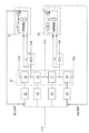
図1は、MRIシステム100(たとえば低磁場MRIシステム)の例示的なコンポーネントのブロック図である。図1のこの例解用の例では、MRIシステム100は、コンピューティング装置104、コントローラ106、パルス・シーケンス記憶部108、電力管理システム110および磁気系コンポーネント120を有する。システム100が例示的であり、MRIシステムは、図1に示したコンポーネントに加えて、またはその代わりに、任意の好適な型の一つまたは複数の他のコンポーネントを有していてもよいことは理解しておくべきである。
FIG. 1 is a block diagram of an exemplary component of an MRI system 100 (eg, a low field MRI system). In this exemplary example of FIG. 1, the
図1に示されるように、磁気系コンポーネント120はB0磁石122、シム・コイル124、RF送信および受信コイル126および傾斜コイル128を有する。磁石122は、主磁場B0を生成するために使用されうる。磁石122は、所望される主磁場B0を生成できる磁気系コンポーネントのいかなる好適な型または組み合わせであってもよい(たとえば、電磁石、プリントされた磁気系、永久磁石などの任意のものまたは組み合わせ)。このように、本稿ではB0磁石とは、B0場を生成するよう構成された任意の型の磁気系コンポーネントの任意の一つまたは組み合わせをいう。いくつかの実施形態によれば、B0磁石122は、約20mT以上かつ約50mT以下、約50mT以上かつ約0.1T以下、約0.1T以上かつ約0.2T以下、約0.2T以上かつ約0.3T以下、約0.3T以上かつ約0.5T以下などのB0場を生成するまたはそれに寄与するのでもよい。シム・コイル124は、磁石122によって生成されるB0場の均一性を改善するための磁場(単数または複数)を寄与するために使われてもよい。
As shown in FIG. 1, the
傾斜コイル128は、傾斜場を提供するよう構成されてもよく、たとえば、三つの実質的に直交する方向(X,Y,Z)におけるB0場内の勾配を生成するよう構成されてもよい。傾斜コイル128は、受信されるMR信号の空間位置を周波数または位相の関数としてエンコードするためにB0場(磁石122および/またはシム・コイル124によって生成されるB0場)を系統的に変化させることによって、放出されるMR信号をエンコードするよう構成されてもよい。たとえば、傾斜コイル128は、周波数または位相を特定の方向に沿った空間位置の線形関数として変化させるよう構成されてもよい。ただし、非線形傾斜コイルを使って、より複雑な信号エンコード・プロファイルが提供されてもよい。たとえば、第一の傾斜コイルが第一(X)の方向におけるB0場を選択的に変化させてその方向の周波数エンコードを実行するよう構成されてもよく、第二の傾斜コイルが第一の方向と実質的に直交する第二(Y)の方向におけるB0場を選択的に変化させて位相エンコードを実行するよう構成されてもよく、第三の傾斜コイルが第一および第二の方向に実質的に直交する第三(Z)の方向におけるB0場を選択的に変化させて体積撮像用途のためのスライス選択を可能にするよう構成されてもよい。
The
上記で論じたように、MRIは、それぞれ送信および受信コイル(しばしば高周波(RF)コイルと称される)を使って励起し、放出されるMR信号を検出することによって実行される。送受信コイルは、送信および受信のための別個のコイル、送信および/または受信のための複数のコイル、あるいは送信および受信のための同じコイルを含んでいてもよい。MRIシステムの送信および受信磁気系コンポーネントについてのさまざまな構成を一般的に指すために、送受信コイルはしばしばTx/RxまたはTx/Rxコイルとも称される。これらの用語は本稿では交換可能に使われる。図1では、RF送信および受信コイル126は、振動磁場B1を誘起するためのRFパルスを生成するために使われうる一つまたは複数の送信コイルを有する。該送信コイルは、いかなる好適な型のRFパルスを生成するよう構成されてもよい。たとえば、送信コイルは、2015年11月11日に出願された「低磁場磁気共鳴のためのパルス・シーケンス」という名称の米国特許出願第14/938,430号('430出願)に記載されるパルス・シーケンスの任意のものを生成するよう構成されてもよい。
As discussed above, MRI is performed by detecting the MR signal that is excited and emitted using the transmit and receive coils (often referred to as radio frequency (RF) coils), respectively. The transmit and receive coils may include separate coils for transmit and receive, multiple coils for transmit and / or receive, or the same coil for transmit and receive. Transmit and receive coils are often also referred to as Tx / Rx or Tx / Rx coils to generally refer to the different configurations of transmit and receive magnetic system components in an MRI system. These terms are used interchangeably in this paper. In FIG. 1, the RF transmit and receive
磁気系コンポーネント120のそれぞれは、いかなる好適な仕方で構築されてもよい。たとえば、いくつかの実施形態では、磁気系コンポーネント120の一つまたは複数(たとえば全部)は、2015年9月4日に出願された、「低磁場磁気共鳴撮像の方法および装置」という名称の米国特許出願第14/845,652号('652出願)において記載されている技法を使って製作、構築または製造されてもよい。しかしながら、本稿に記載される技法はこの点で限定されるものではなく、任意の好適な技法が磁気系コンポーネント120を提供するために使用されうる。
Each of the
電力管理システム110は、低磁場MRIシステム100の一つまたは複数のコンポーネントに動作電力を提供するための電子回路を含む。たとえば、下記でより詳細に論じるように、電力管理システム110は一つまたは複数の電源、傾斜電力コンポーネント、送信コイル・コンポーネントおよび/または低磁場MRIシステム100のコンポーネントにエネルギーを与え動作させるために好適な動作電力を提供するために必要とされる他の任意の好適な電力電子系統を含みうる。
The
図1に示されるように、電力管理システム110は、電源112、電力コンポーネント(単数または複数)114、送受切り換えスイッチ116および熱管理コンポーネント118を有する。電源112は、MRIシステム100の磁気系コンポーネント120に動作電力を提供するための電子回路を含む。たとえば、電源112は一つまたは複数のB0コイル(たとえばB0磁石122)に、低磁場MRIシステムのための主磁場を生成するよう動作電力を提供するための電子回路を含んでいてもよい。いくつかの実施形態では、電源112は単極の(unipolar)連続波(CW)電源であるが、いかなる好適な電源が使われてもよい。送受切り換えスイッチ116は、RF送信コイルまたはRF受信コイルのどちらが動作させられるかを選択するために使われてもよい。
As shown in FIG. 1, the
電力コンポーネント(単数または複数)114は、一つまたは複数のRF受信コイル(たとえばコイル126)によって検出されるMR信号を増幅する一つまたは複数のRF受信(Rx)前置増幅器、一つまたは複数のRF送信コイル(たとえばコイル126)に電力を提供するよう構成された一つまたは複数のRF送信(Tx)電力コンポーネント、一つまたは複数の傾斜コイル(たとえば傾斜コイル128)に電力を提供するよう構成された一つまたは複数の傾斜電力コンポーネントおよび一つまたは複数のシム・コイル(たとえばシム・コイル124)に電力を提供するよう構成された一つまたは複数のシム電力コンポーネントを含んでいてもよい。 The power component (s) 114 is one or more RF receive (Rx) pre-amplifiers, one or more, that amplify the MR signal detected by one or more RF receive coils (eg coil 126). One or more RF transmit (Tx) power components configured to power an RF transmit coil (eg, coil 126), to power one or more tilt coils (eg, tilt coil 128). It may include one or more tilted power components configured and one or more shim power components configured to power one or more shim coils (eg, shim coil 124). ..
熱管理コンポーネント118は、低磁場MRIシステム100のコンポーネントについての冷却を提供する。これは、低磁場MRIシステム100の一つまたは複数のコンポーネントによって生成される熱エネルギーをそれらのコンポーネントから去らせる伝達を容易にすることによって行なってもよい。熱管理コンポーネント118は、限定なしに、B0コイル、傾斜コイル、シム・コイルおよび/または送受信コイルを含むがそれに限定されない、熱を生成するMRIコンポーネントに統合されるまたは近接して配置されるのでもよい、水冷式または空冷式の冷却を実行するためのコンポーネントを含んでいてもよい。熱管理コンポーネント118は、低磁場MRIシステム100のコンポーネントから去るよう熱を伝達するために、空気および液体冷却材(たとえば水)を含むがそれに限定されないいかなる好適な熱伝達媒体を含んでいてもよい。
Thermal management component 118 provides cooling for the components of the low
図1に示されるように、MRIシステム100は、電力管理システム110に命令を送り、これから情報を受け取る制御電子回路を有するコントローラ106(コンソールとも称される)を含んでいる。コントローラ106は一つまたは複数のパルス・シーケンスを実装するよう構成されてもよい。パルス・シーケンスは、磁気系コンポーネント120を所望されるシーケンスで動作させるために電力管理システム110に送られる命令を決定するために使われる。たとえば、MRIシステム100が低磁場で動作する実施形態については、コントローラ106は、ゼロ・エコー時間(LF-ZTE: low-field zero echo time)パルス・シーケンス、均衡定常状態自由歳差(bSSFP: balanced steady-state free precession)パルス・シーケンス、グラジエントエコー・パルス・シーケンス、スピンエコー・パルス・シーケンス、反転回復パルス・シーケンス、動脈スピン標識付け、拡散強調撮像(DWI)および/または低磁場コンテキストでの動作のために規定される他の任意のパルス・シーケンスに従って磁気系コンポーネント120を動作させるよう電力管理システム110を制御するよう構成されてもよい。低磁場MRIのためのパルス・シーケンスは、T1強調およびT2強調撮像、拡散強調撮像、動脈スピン標識付け(灌流画像化)、オーヴァーハウザー撮像などといった種々のコントラスト型について適用されうる。しかしながら、いかなるパルス・シーケンスが使われてもよく、諸側面はこの点で限定されない。コントローラ106は、ハードウェア、ソフトウェアまたはハードウェアとソフトウェアの任意の好適な組み合わせとして実装されうる。本稿で与えられる開示の諸側面はこれに関して限定されない。
As shown in FIG. 1, the
いくつかの実施形態では、コントローラ106は、一つまたは複数のパルス・シーケンスのそれぞれについての情報を記憶しているパルス・シーケンス貯蔵部108からパルス・シーケンスについての情報を得ることによって、パルス・シーケンスを実装するよう構成されてもよい。特定のパルス・シーケンスについてパルス・シーケンス貯蔵部108に記憶されている情報は、コントローラ106がその特定のパルス・シーケンスを実装できるようにするいかなる好適な情報であってもよい。たとえば、パルス・シーケンスについてパルス・シーケンス貯蔵部108に記憶されている情報は、そのパルス・シーケンスに従って磁気系コンポーネント120を動作させるための一つまたは複数のパラメータ(たとえば、RF送信および受信コイル126を動作させるためのパラメータ、傾斜コイル128を動作させるためのパラメータなど)、そのパルス・シーケンスに従って電力管理システム110を動作させるための一つまたは複数のパラメータ、コントローラ106によって実行されたときにコントローラ106がシステム100を制御してそのパルス・シーケンスに従って動作するようにする命令を含む一つまたは複数のプログラムおよび/または他の任意の好適な情報を含んでいてもよい。パルス・シーケンス貯蔵部108に記憶されている情報は、一つまたは複数の非一時的な記憶媒体に記憶されていてもよい。
In some embodiments, the
図1に示されるように、コントローラ106は、受信されたMRデータを処理するようプログラムされたコンピューティング装置104とも対話する。たとえば、コンピューティング装置104は、任意の好適な画像再構成プロセスを使って、受信されたMRデータを処理して一つまたは複数のMR画像を生成してもよい。コントローラ106は、一つまたは複数のパルス・シーケンスについての情報を、コンピューティング装置によるデータの該処理のために、コンピューティング装置104に提供してもよい。たとえば、コントローラ106は、一つまたは複数のパルス・シーケンスについての情報をコンピューティング装置104に提供してもよく、コンピューティング装置は少なくとも部分的には該提供された情報に基づいて画像再構成プロセスを実行してもよい。
As shown in FIG. 1, the
コンピューティング装置104は、収集されたMRデータを処理して、撮像される被験体の一つまたは複数の画像を生成しうるいかなる電子装置であってもよい。いくつかの実施形態では、コンピューティング装置104は、固定電子装置、たとえばデスクトップ・コンピュータ、サーバー、ラックマウント・コンピュータ、ワークステーションまたは他の任意の好適な固定電子装置であってMRデータを処理して撮像される被験体の一つまたは複数の画像を生成するよう構成されうるものであってもよい。あるいはまた、コンピューティング装置104は、ポータブル装置、たとえばスマートフォン、携帯情報端末、ラップトップ・コンピュータ、タブレット・コンピュータまたはMRデータを処理して撮像される被験体の一つまたは複数の画像を生成するよう構成されうる他の任意のポータブル装置であってもよい。いくつかの実施形態では、コンピューティング装置104はいかなる好適な型の複数のコンピューティング装置を有していてもよい。本稿で与えられる開示の諸側面はこれに関して限定されない。低磁場MRシステム100の諸側面を制御する(たとえば特定のパルス・シーケンスに従って動作するようシステム100をプログラムする、システム100の一つまたは複数のパラメータを調整するなど)および/または低磁場MRIシステム100によって得られた画像を見るために、ユーザー102がコンピューティング装置104と対話してもよい。
The computing device 104 may be any electronic device capable of processing the collected MR data to produce one or more images of the subjects to be imaged. In some embodiments, the computing device 104 is a fixed electronic device such as a desktop computer, server, rack mount computer, workstation or any other suitable fixed electronic device that processes MR data. It may be configured to produce one or more images of the subject to be imaged. Alternatively, the computing device 104 may process a portable device such as a smartphone, personal digital assistant, laptop computer, tablet computer or MR data to generate one or more images of the subject to be imaged. It may be any other portable device that can be configured. In some embodiments, the computing device 104 may have a plurality of computing devices of any suitable type. The aspects of disclosure given in this paper are not limited in this regard. Controlling aspects of the low-field MR system 100 (eg, programming the
上記で論じたように、発明者は、高磁場MRIシステムのコイルを駆動するための通常の電力コンポーネントは一般に、低ノイズでコイルを駆動するようには設計されていないので、低磁場MRIシステムのためには不適であることを認識した。そのような電力コンポーネントによって注入されるノイズは、高いSNRをもつ高磁場MRIシステムでは受け入れ可能であることがあるが、そのような電力コンポーネントは、低磁場MRIシステムにおいて受け入れ可能な画質を提供するのに十分低いノイズ・レベルを提供しない。低磁場MRIの低いSNRは、低磁場MRIシステムの一つまたは複数のコイルを駆動するための低ノイズ電力コンポーネントの必要性を増す。低ノイズ電力コンポーネントの設計は、低磁場MRIシステムのSNRを改善できる。 As discussed above, the inventor of the low magnetic field MRI system, because the usual power components for driving the coil of a high magnetic field MRI system are generally not designed to drive the coil with low noise. I realized that it was not suitable for this. The noise injected by such power components may be acceptable in high field MRI systems with high signal-to-noise ratios, but such power components provide acceptable image quality in low field MRI systems. Does not provide a sufficiently low noise level. The low SNR of low-field MRI increases the need for low-noise power components to drive one or more coils in a low-field MRI system. The design of low noise power components can improve the SNR of low field MRI systems.
いくつかの高磁場MRIシステムは、コイルを流れる電流を駆動するためにスイッチング電力変換器を有する電力コンポーネントを使う。スイッチング電力変換器は高い効率を提供することができるが、発明者は、通常のスイッチング変換器は、パルス・シーケンスの送信およびパルス・シーケンスに応答して放出されるMR信号の検出に影響することのできる範囲(たとえば数十または数百kHzの範囲)の周波数で切り換えを行なうため、システムにかなりの量のスイッチング・ノイズを導入することがあることを認識し、理解した。たとえば、通常のスイッチングされる電力変換器の切り換え周波数および/またはその高調波は、送信および/または受信コイルが共鳴するよう同調されている周波数と重なることがあり、よって、低磁場MRIシステムの送信/受信チャネルにノイズを加えることがある。そのような電力変換器によって注入されるノイズは高磁場MRIシステムでは有意でないかもしれないが、注入されるノイズのレベルは低磁場MRIシステムにおいては受け入れ不可能であることがあり、画質を劣化させることがある。さらに、高磁場MRIにおける送信/受信周波数における差は、典型的にはスイッチング・ノイズがより簡単にフィルタ除去されることを許容する。スイッチング・ノイズが典型的には送信/受信周波数に対して帯域外となるからである(スイッチング周波数および/または高調波はB1周波数(送信周波数)よりずっと低く、よってずっと簡単にフィルタ除去される)。 Some high field MRI systems use a power component with a switching power converter to drive the current through the coil. Although switching power converters can provide high efficiency, the inventor has found that conventional switching transducers affect the transmission of pulse sequences and the detection of MR signals emitted in response to pulse sequences. Recognized and understood that switching at frequencies within the possible range (eg, in the range of tens or hundreds of kHz) can introduce a significant amount of switching noise into the system. For example, the switching frequency and / or its harmonics of a normal switched power converter can overlap the frequency at which the transmit and / or receive coils are tuned to resonate, thus transmitting in a low field MRI system. / May add noise to the receive channel. The noise injected by such a power converter may not be significant in a high field MRI system, but the level of noise injected may be unacceptable in a low field MRI system, degrading image quality. Sometimes. In addition, differences in transmit / receive frequencies in high-field MRI typically allow switching noise to be filtered out more easily. This is because switching noise is typically out of band with respect to the transmit / receive frequency (switching frequencies and / or harmonics are much lower than the B1 frequency (transmit frequency) and are therefore much easier to filter out). ..
スイッチング電力変換器を使うことに対する代替は、線形増幅器を使うことである。完全にオンと完全にオフの状態の間でそのトランジスタを切り換えるスイッチング電力変換器と異なり、線形増幅器はそのトランジスタを連続範囲にわたって動作させて、増幅された出力を生成する。線形増幅器では、制御信号が一つまたは複数のトランジスタの制御端子(たとえばゲートまたはベース)に与えられてもよく、トランジスタ(単数または複数)を流れる電流が制御信号の大きさに基づいて制御される。線形増幅器はその出力を、スイッチング周波数でトランジスタのオン、オフを切り換えるのではなく、トランジスタの電流をある連続範囲にわたって変化させることによって生成するので、スイッチング・ノイズの注入が回避できる。 An alternative to using a switching power converter is to use a linear amplifier. Unlike switching power converters, which switch the transistor between fully on and completely off states, a linear amplifier operates the transistor over a continuous range to produce an amplified output. In a linear amplifier, a control signal may be given to the control terminals (eg, gate or base) of one or more transistors, and the current through the transistors (s) is controlled based on the magnitude of the control signal. .. A linear amplifier produces its output by changing the transistor's current over a continuous range, rather than switching the transistor on and off at the switching frequency, thus avoiding the injection of switching noise.
しかしながら、発明者は、たとえば傾斜コイルのようなMRIシステムのコイルに、幅広い範囲の出力電流および/または電圧が提供される必要があることがあると認識した。よって、正の出力電圧を提供するために単一の正電圧端子を使い、負の出力電圧を提供するために単一の負電圧端子を使う結果、非効率的な電力コンポーネントとなる。特に、線形増幅器は、比較的小さな大きさの出力電圧を生成するときにかなりの電力を散逸することがある。たとえば、線形増幅器の出力における比較的低電圧および高電流を提供することは、供給電圧端子と増幅器の出力端子との間で増幅器のトランジスタ(単数または複数)をまたいだ大きな電圧降下を要求することがある。よって、そのような線形増幅器は、低出力電圧を生成するよう動作させられるときには非効率的であることがあり、結果として、かなりの電力を消費し、かなりの熱散逸を生じることがある。システムを冷却するために冷却システムが使われてもよいが、増幅器回路のためにかなりの冷却機能を設けることはいくつかのMRIシステム、たとえば比較的小型、軽量および/または低コストであるよう設計される低磁場MRIシステムについては、受け入れ可能ではないことがある。 However, the inventor has recognized that coils in MRI systems, such as tilted coils, may need to be provided with a wide range of output currents and / or voltages. Thus, using a single positive voltage terminal to provide a positive output voltage and a single negative voltage terminal to provide a negative output voltage results in an inefficient power component. In particular, linear amplifiers can dissipate significant power when producing relatively small magnitude output voltages. For example, providing relatively low voltage and high current at the output of a linear amplifier requires a large voltage drop across the amplifier's transistors (s) between the supply voltage terminal and the amplifier's output terminal. There is. Thus, such linear amplifiers can be inefficient when operated to produce low output voltages, resulting in significant power consumption and significant heat dissipation. A cooling system may be used to cool the system, but providing significant cooling for the amplifier circuit is designed to be relatively small, lightweight and / or low cost for some MRI systems, for example. The low magnetic field MRI system used may not be acceptable.
発明者は、線形増幅器を利用する電力コンポーネントの効率が、増幅器によって生成される出力電圧に基づいて異なる供給電圧(たとえば異なる固定電圧の複数の供給レール)から増幅器に電力を与えることによって改善されうることを認識した。増幅器を異なる供給電圧に接続する機能を設けることによって、増幅器の出力電圧により近い適切な供給電圧が選択されることができ、このことは増幅器のトランジスタにまたがる電圧降下を減らすことができる。よって、増幅器の効率を増すことができ、増幅器を冷却するための要件が著しく軽減できる、あるいはなくせる。そのような増幅器は、上記のように効率的な低ノイズ電力コンポーネントから裨益できる低磁場MRIシステムでは特に有利でありうる。 The inventor can improve the efficiency of a power component utilizing a linear amplifier by powering the amplifier from different supply voltages (eg, multiple supply rails with different fixed voltages) based on the output voltage produced by the amplifier. I realized that. By providing the function of connecting the amplifier to different supply voltages, an appropriate supply voltage closer to the output voltage of the amplifier can be selected, which can reduce the voltage drop across the transistors of the amplifier. Thus, the efficiency of the amplifier can be increased and the requirement for cooling the amplifier can be significantly reduced or eliminated. Such amplifiers can be particularly advantageous in low field MRI systems that can benefit from efficient low noise power components as described above.
図2は、いくつかの実施形態に基づく、所望されるパルス・シーケンスに従って磁場を生成するようMRIシステムのコイル202を流れる電流を駆動するための駆動回路を示している。電力コンポーネント114は、コントローラ106からの制御信号に基づいてコイル202を流れる電流を駆動する。コントローラ106は、コントローラ106によって実装される(または一つまたは複数の他のコントローラによって提供される)パルス・シーケンスに基づいて電力コンポーネント114を駆動するよう制御信号を生成してもよい。いくつかの実施形態では、コイル202は傾斜コイル128であってもよい。しかしながら、本稿に記載される技法はこの点で限定されない。コイル202は磁石122のコイル、シム・コイル124またはRF送信および/または受信コイル126でありうる。
FIG. 2 shows a drive circuit for driving a current through
傾斜コイルに電力を与えるよう構成された電力コンポーネントは、典型的には比較的高い電力を提供し、典型的には、所望されるパルス・シーケンスを忠実に送達できるよう、傾斜コイルに提供される電流に対する精密な制御を提供する必要がある。指令された電流を傾斜コイルに送達することにおける不正確さは、送達される傾斜パルス・シーケンスと意図される(そして期待される)パルス・シーケンスとの間の差に起因する信号対雑音比の低下につながる。傾斜コイルを駆動するよう構成された電力コンポーネントは、所望されるパルス・シーケンスによって要求される電流波形を忠実に生成するよう、指令された電流を傾斜コイルに送達することにおいて応答がよいべきでもある。それには指令された電流レベルの間で迅速に遷移することも含まれる。よって、発明者は、所望されるパルス・シーケンスを忠実に再現するために一つまたは複数の傾斜コイルに比較的低いノイズおよび比較的高い効率をもって電流を正確かつ精密に提供するよう制御されることのできる電力コンポーネントを開発した。そのいくつかの実施形態を下記でより詳細に論じる。 Power components that are configured to power the tilt coil are typically provided to the tilt coil to provide relatively high power and typically to faithfully deliver the desired pulse sequence. It is necessary to provide precise control over the current. The inaccuracy in delivering the commanded current to the tilt coil is the signal-to-noise ratio due to the difference between the gradient pulse sequence delivered and the intended (and expected) pulse sequence. It leads to a decline. Power components configured to drive the tilt coil should also be responsive in delivering the directed current to the tilt coil to faithfully produce the current waveform required by the desired pulse sequence. .. It also includes a rapid transition between the commanded current levels. Thus, the inventor is controlled to accurately and precisely deliver current to one or more tilted coils with relatively low noise and relatively high efficiency in order to faithfully reproduce the desired pulse sequence. Developed a power component that can be used. Some of its embodiments will be discussed in more detail below.
いくつかの実施形態では、電力コンポーネント114は、コイル202を通じて所望される電流を駆動する「電流モード」電力コンポーネントであってもよい。所望される電流は、コントローラ106からの電流コマンドに応答して電力コンポーネント114によって生成されてもよい。これに関し、電力コンポーネント114は、電流コマンド(これはコイル202に提供されるべき電流を示す電圧レベルとしてコントローラによって提供されてもよい)によって制御される電流源として動作してもよい。コントローラ106は、電力コンポーネント114が選択されたパルス・シーケンスに従って変化する電流値を生成するよう電流コマンドを変化させてもよい。たとえば、コントローラ106は、複数の傾斜パルスを含むパルス・シーケンスに従って一つまたは複数の傾斜コイルを駆動するよう電力コンポーネントに指令〔コマンド〕してもよい。各傾斜パルスについて、電力コンポーネントは、傾斜パルスの上昇端において対応する傾斜コイルに与えられる電流を傾斜状に上昇させ、傾斜パルスの下降端において該傾斜コイルに与えられる電流を傾斜状に低下させる必要があることがある。複数のそのような傾斜パルスを与えるよう傾斜コイルを駆動するよう構成された電力コンポーネントの例示的な動作は下記でさらに詳細に記載される。
In some embodiments, the
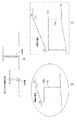
図3のAは、いくつかの実施形態に基づく、傾斜コイル電流波形の例を示している。この例では、傾斜コイル電流は、傾斜パルスの上昇端において0Aから+20Aまで0.2msの時間期間内に急速に傾斜状に上昇し、ある時間期間にわたって+20Aに留まり、次いで傾斜パルスの下降端において−20Aまで急速に傾斜状に低下し、ある時間期間にわたって−20Aに留まる。傾斜パルスを生成するための上記の例示的な電流は例解のために与えられているのであって、異なるパルス・シーケンスは異なる電流および/または電圧要件をもつ異なる傾斜パルスを含んでいてもよいことは理解しておくべきである。コントローラ106および電力コンポーネント114は、いかなる好適なパルス・シーケンスに従って一つまたは複数の傾斜コイルを駆動するよう構成されることもできる。
FIG. 3A shows an example of a tilted coil current waveform based on some embodiments. In this example, the tilt coil current rapidly ramps from 0A to + 20A at the rising end of the tilt pulse within a time period of 0.2ms, stays at + 20A over a period of time, and then-at the falling end of the tilt pulse. It drops rapidly to 20A and stays at -20A for a period of time. The above exemplary currents for generating gradient pulses are given for illustration purposes, and different pulse sequences may include different gradient pulses with different current and / or voltage requirements. That should be understood. The
図3のBは、図3のAに示した傾斜コイルの上昇端の前、間および後の、電流コマンド、傾斜コイル電流および傾斜コイル電圧についての波形を示している。傾斜コイル電流は傾斜コイルを流れる電流である。傾斜コイル電圧は傾斜コイルにまたがる電圧である。電流コマンドは、電力コンポーネント114によって傾斜コイルを通じて駆動される電流の量を表わす信号である。時刻0msにおける電流コマンドに応答して、傾斜コイルを流れる電流は+20Aの指令された電流に向けて上昇し始める。傾斜コイルは誘導負荷なので、傾斜コイルを流れる電流を急速に増すためには、比較的大きな電圧が傾斜コイルに提供される必要がある。傾斜コイルを流れる電流の急速な上昇を提供することは、MRI用途において望ましい。傾斜コイル電流値の間の高速な遷移を提供することは収集時間を短縮でき、ある種のパルス・シーケンスを実装するために必要とされることもあるからである。図3のAおよびBに示された例示的な電圧および電流から理解されるはずであるが、電力コンポーネント114は、比較的高い電力をもって傾斜コイルを駆動する機能を有していてもよい。
B in FIG. 3 shows waveforms for the current command, tilt coil current and tilt coil voltage before, during and after the rising end of the tilt coil shown in A in FIG. The tilt coil current is the current flowing through the tilt coil. The tilt coil voltage is a voltage that spans the tilt coil. The current command is a signal that represents the amount of current driven through the tilt coil by the
例として、傾斜コイルは200μHのインダクタンスおよび100mΩの抵抗をもっていてもよい。傾斜コイルを流れる電流の変化率はそのインダクタンスに比例するので、傾斜コイルの電流を100A/msのレートで増すためには、100Vの電圧が傾斜コイルに与えられる必要がある。しかしながら、ひとたび傾斜コイルの電流が20Aで水平になったら、電圧要件は実質的に低下する。この時点で、電流はもはや変化しないので、必要とされる電圧は傾斜コイルの抵抗に依存する。傾斜コイルの抵抗が100mΩであるので、電流を20Aで定常に維持するために傾斜コイルに提供される必要のある電圧は2Vである。これは、電流値と電流値の間の遷移の際に必要とされる電圧(100V)より著しく低い。しかしながら、電流、電圧、インダクタンスおよび抵抗のこれらの値は単に例として与えられているのであって、いかなる好適な傾斜コイル設計が使われてもよく、それらはインダクタンスおよび/または抵抗の異なる値をもつことがある。さらに、電流、電圧、遷移タイミングなどの他の好適な値が、所与のパルス・シーケンスを実装するために使われるおよび/または必要とされることがありうる。 As an example, a tilted coil may have an inductance of 200 μH and a resistance of 100 mΩ. Since the rate of change of the current flowing through the tilt coil is proportional to its inductance, a voltage of 100 V must be applied to the tilt coil in order to increase the tilt coil current at a rate of 100 A / ms. However, once the tilt coil current is level at 20A, the voltage requirement is substantially reduced. At this point, the current no longer changes, so the required voltage depends on the resistance of the tilt coil. Since the resistance of the tilt coil is 100 mΩ, the voltage that needs to be provided to the tilt coil to keep the current steady at 20 A is 2 V. This is significantly lower than the voltage (100V) required for the transition between current values. However, these values for current, voltage, inductance and resistance are given by way of example only, any suitable tilted coil design may be used and they have different values for inductance and / or resistance. Sometimes. In addition, other suitable values such as current, voltage, transition timing, etc. may be used and / or required to implement a given pulse sequence.
傾斜コイルの抵抗は比較的低いので(たとえば500mΩ未満)、いくつかの実施形態では、電力コンポーネント114は、指令された電流を効率的に供給するために、比較的低い出力インピーダンスをもつ。たとえば、いくつかの実施形態によれば、電力コンポーネント114は、一つまたは複数の傾斜コイルに電力を与える(たとえば前記一つまたは複数の傾斜コイルに所望されるパルス・シーケンスに従って電流を与える)よう構成された線形増幅器を有する。低い出力インピーダンスをもつ線形増幅器を実装するために、低い等価直列抵抗をもつ好適なサイズの諸トランジスタが使われてもよく、および/または集団的に低抵抗を生じるためにいくつかのトランジスタが並列に接続されてもよい。比較的低い抵抗をもつよう相互接続が設計されてもよい。線形増幅器の出力インピーダンスはたとえば、いくつかの実施形態では、傾斜コイルのインピーダンスの二倍未満であってもよい。いくつかの実施形態では、線形増幅器のトランジスタにまたがる電圧降下は、動作においては、5V未満、2V未満または1V未満(かつ0Vより大きい)など、比較的低くてもよい。比較的低い出力インピーダンスをもつ増幅器を使うことは、実質的なDC電流をもつことがある傾斜コイルを流れる電流を駆動するために特に有用であってもよい。低い出力インピーダンスは、増幅器の効率を改善し、加熱を制限することができる。例示的な線形増幅器実装の詳細は書きでより詳細に論じる。
Due to the relatively low resistance of the tilt coil (eg less than 500 mΩ), in some embodiments the
図4Aは、いくつかの実施形態に基づく、電流フィードバック・ループおよび電圧フィードバック・ループをもつ電力コンポーネント114の例を示している。電力コンポーネント114は、所望されるパルス・シーケンスに従って一つまたは複数の傾斜コイルを駆動するために必要とされる電流を提供するよう構成される。よって、電力コンポーネント114は、所望される傾斜磁場を忠実に生成するよう前記一つまたは複数の傾斜コイルを駆動するために必要とされる指令される電流波形を提供するよう精密に制御されることができる、低ノイズ電流源であるよう設計される。電力コンポーネント114は、その非反転入力端子においてコントローラ106からの電流コマンドを、その反転入力端子において電流センサー401からの電流フィードバック信号FBを受け取る比較器301を含んでいる。電流コマンドは、指令される電流を表わす電圧値であってもよい。電流フィードバック信号FBは、測定された電流を表わす電圧値であってもよい。いくつかの実施形態では、正確なフィードバック信号FBを提供するために、高品質電流センサーが使われてもよい。これは傾斜コイル電流パルスの正確さを改善できる。
FIG. 4A shows an example of a
比較器301は、電流コマンドと電流フィードバック信号FBとの間の差を表わす誤差信号E(たとえば電圧)を生成する。増幅器回路302は誤差信号を増幅して増幅された誤差信号を生成し、それが出力段303に提供される。出力段303は、増幅された誤差信号に基づいてコイル202を駆動する。コイル202を流れる電流は電流センサー401によって測定され、上記で論じたようにフィードバック信号FBが比較器301にフィードバックされる。それにより、電流フィードバック・ループはコイル202を流れる電流を、コントローラ106によって指令される電流に等しくする。これに関し、電力コンポーネント114は、電圧制御された電流源として動作してもよい。いくつかの実施形態によれば、傾斜コイルに与えられる電流出力がコントローラ106によって指令される電流を正確に追跡することを保証するために、高い正確さ、高い精度の電流センサー401が使われる。結果として、傾斜コイルに電力を与えるために提供される電流は、現実的に可能な限り指令される電流に近く保持されることができる。電力コンポーネント114は、出力段303の出力電圧を電圧増幅器回路302の入力に提供する電圧フィードバック・ループをももつ。
The
図4Bに示されるように、電圧増幅器回路302は、その非反転入力において誤差信号Eを、その反転入力において電圧フィードバック信号V_FBを受領する演算増幅器OAを含んでいてもよい。電圧フィードバック信号は、抵抗性の電圧分割器(たとえば抵抗器R1およびR2を含む)を通じて演算増幅器の反転入力に提供されてもよい。それにより、演算増幅器は、電圧分割器における抵抗値の比に基づいて入力電圧を増幅する。電圧増幅器のためにいかなる好適な電圧利得が使われてもよい。たとえば5〜15の利得である。いくつかの実施形態では、出力段の電圧利得は1であってもよい。
As shown in FIG. 4B, the
図4Aに示されるように、いくつかの実施形態では、コントローラ106は、出力段303にコマンドを与えてもよい。コントローラ106は出力段303に、パルス・シーケンスの対応する部分を実行するために必要とされる電流を供給するために好適な電源電圧を生成するよう指令〔コマンド〕してもよい。一例として、該コマンドは、出力段の電力変換器に、傾斜コイル電流パルスに先立って電源電圧の大きさを傾斜状に上昇させ始めさせてもよい。そのようなコマンドは、図15Dを参照して下記でより詳細に論じる。
As shown in FIG. 4A, in some embodiments, the
いくつかの実施形態では、出力段303は、異なる電圧での複数の電源端子によって選択的に電力を与えられるよう構成される。出力段303に電力を与えるよう選択される電源端子は、電圧増幅器によって生成される出力電圧に依存して選ばれてもよい。たとえば、電力コンポーネントが比較的高い(正の)出力電圧を生成するよう指令されるときは、電力コンポーネントは比較的高い(正の)電圧供給端子から電力を与えられてもよく、電力コンポーネントが比較的低い(正の)出力電圧を生成するよう指令されるときは、電力コンポーネントは比較的低い(正の)電圧供給端子から電力を与えられる。よって、比較的低い出力電圧が生成されるときに電力コンポーネントのトランジスタにまたがる電圧降下を低減することによって、電力コンポーネントの効率が改善できる。任意の数の供給端子および電圧レベルが使われてもよいことは理解しておくべきである。諸側面はこの点で限定されない。たとえば、高、中、低の電圧供給端子(正および負両方)が使われてもよく、特定の設計および/または実装のために好適なよりも多数が使われてもよい。
In some embodiments, the
図5Aは、磁気共鳴撮像システムの一つまたは複数の傾斜コイルに電力を与えるために好適な出力Vout、Ioutをもつ出力段303Aの例を示している。一つまたは複数の傾斜コイルに電力を与える電力効率を改善するために、出力段303Aが、出力電圧Voutに依存して異なる供給端子によって電力を与えられることができる。たとえば、出力段303Aは、第一の極性の複数の供給端子(たとえば、複数の異なる正電圧)および/または第二の極性の複数の供給端子(たとえば、複数の異なる負電圧)によって電力を与えられることができる。低ノイズ動作を容易にするために、いくつかの実施形態によれば、出力段303Aは線形増幅器304を含んでいてもよい。何らかの実施形態によれば、異なる供給端子のそれぞれは、異なる固定した供給電圧を与える。いくつかの実施形態によれば、異なる供給端子の一つまたは複数が、下記でより詳細に論じるように、可変供給電圧を生成する。
FIG. 5A shows an example of an
動作では、正の出力電圧がVoutにおいて生成される場合、スイッチング回路S1は線形増幅器304の高い側の電力入力を、出力電圧の大きさに依存して、高電圧端子+Vhighまたは低電圧端子+Vlowのいずれかに接続する。相対的に高い出力電圧が生成される場合(たとえば生成されるべき出力電圧が特定の閾値を超える場合)には、スイッチング回路S1は線形増幅器304の高い側の電力入力を高電圧端子+Vhighに接続する。相対的に低い出力電圧が生成される場合(たとえば生成されるべき出力電圧が前記特定の閾値より低いままである場合)には、スイッチング回路S1は線形増幅器304の高い側の電力入力を低電圧端子+Vlowに接続する。同様に、負の出力電圧が生成される場合には、スイッチング回路S2が、線形増幅器304の低い側の電力入力を、上記で論じたように出力電圧の大きさに依存して、高電圧端子−Vhighまたは低電圧端子−Vlowのいずれかに接続する。いかなる好適なスイッチング回路S1およびS2が使われてもよい。そのようなスイッチング回路は、受動的に切り換えられるダイオードおよび/または能動的に切り換えられるトランジスタを含んでいてもよい。
In operation, if a positive output voltage is generated in Vout, the switching circuit S1 will take the power input on the higher side of the
いくつかの実施形態では、高電圧または低電圧端子は、介在するスイッチS1やS2なしに線形増幅器304に直接接続されてもよい。たとえば、図5Bに示される例示的な出力段303A’に示されるように、高電圧端子+Vhighおよび−Vhighは線形増幅器304に直接接続されてもよく、低電圧端子+Vlowおよび−Vlowは線形増幅器304にそれぞれのスイッチS1およびS2を通じて接続されてもよい。線形増幅器304は、その電圧が出力電流を供給するために不十分であるのでない限り低電圧出力端子によって電力を与えられ、不十分である場合には線形増幅器304は高電圧供給端子によって電力を与えられるように設計されてもよい。+−Vhighおよび+−Vlowの使用は単に例示的であり、所望される出力電圧を提供するために使用されうる任意の数の電圧レベルが使われてもよいことは理解しておくべきである。たとえば、+−Vhighと+−Vlowの間の一つまたは複数の中間の電圧レベルが、所望される電圧レベルを生成するために使われてもよい。
In some embodiments, the high or low voltage terminals may be directly connected to the
図6は、複数の駆動回路601〜604を有する出力段303Aの例を示している。駆動回路601〜604は、複数のトランジスタ回路605〜608を含む線形増幅器304を駆動する。各トランジスタ回路は一つまたは複数のトランジスタを含む。線形増幅器304は、生成されるべき出力電圧に依存して高電圧または低電圧の供給端子に接続されることができる。
FIG. 6 shows an example of an
低い正の出力電圧が生成されるときは、トランジスタ606はスイッチ回路S3を介して低電圧端子+Vlowに接続される。トランジスタ605は駆動回路601によってオフにされて、トランジスタ606を高電圧端子+Vhighから切り離す。駆動回路602は、入力に基づいて、トランジスタ606を線形増幅素子として駆動して、電流源として低電圧端子+Vlowを使って、増幅された出力を生成する。
When a low positive output voltage is generated, the
高い正の出力電圧を提供するためには、駆動回路601はトランジスタ605をオンにして、高電圧端子+Vhighをトランジスタ606に接続する。スイッチ回路S3は、低電圧端子+Vlowからトランジスタ606を切り離すためにオフにされてもよい。駆動回路602はトランジスタ606を完全にオンに駆動してもよい。それによりトランジスタ605は出力段303Aの出力に接続される。駆動回路601は、入力に基づいて、トランジスタ605を線形増幅素子として駆動して、高電圧端子+Vhighを使って、増幅された出力を生成する。
In order to provide a high positive output voltage, the
このように、低電圧端子+Vlowは低い出力電圧を提供するために使用でき、高電圧端子+Vhighは高い出力電圧を提供するために使用できる。負の出力電圧は駆動回路603および604、トランジスタ607および608およびスイッチ回路S4によって同様に提供されてもよい。負の出力電圧が生成されるとき、駆動回路601および602はトランジスタ605および606をオフにしてもよい。同様に、正の出力電圧が生成されるときは、駆動回路603および604がトランジスタ607および608をオフにしてもよい。
Thus, the low voltage terminal + Vlow can be used to provide a low output voltage and the high voltage terminal + Vhigh can be used to provide a high output voltage. Negative output voltages may be similarly provided by
トランジスタ606は、低い出力電圧のために線形増幅器304の線形増幅素子として動作してもよく、トランジスタ605は、高い出力電圧のために線形増幅素子として動作してもよい。いくつかの実施形態では、トランジスタ606および605は、低い正の出力電圧と高い正の出力電圧との間の遷移領域についてはトランジスタ605および606の両方が線形増幅器304の線形増幅素子として作用するようバイアスをかけられてもよい。すなわち、両方とも完全にオンにも完全にオフにもならない。そのような遷移の際にトランジスタ605および606の両方を線形素子として動作させることは、なめらかで連続的な伝達関数をもつ線形増幅器304を容易にしうる。トランジスタ607および608は、ある範囲の負の出力電圧を生成するために、トランジスタ605および606と同様に動作してもよい。
The
いくつかの実施形態では、スイッチ回路S3およびS4は、高電圧端子が利用されているかどうかに依存して自動的にオンおよびオフに切り換わるダイオードによって実現されてもよい。たとえば、スイッチ回路S3がダイオードを含む場合、アノードは端子+Vlowに、カソードはトランジスタ606に接続されてもよく、それにより電流は端子+Vlowから出力段303Aに流出できるだけとなる。しかしながら、本稿に記載される技法は、この点で限定されない。スイッチ回路S3およびS4は、トランジスタのような制御されたスイッチまたは他の任意の好適なスイッチング回路を使って実現されてもよい。
In some embodiments, the switch circuits S3 and S4 may be implemented by diodes that automatically switch on and off depending on whether the high voltage terminals are utilized. For example, if the switch circuit S3 includes a diode, the anode may be connected to the terminal + Vlow and the cathode may be connected to the
いくつかの実施形態では、図6の回路は、図3に示されるパルス・シーケンスを使って傾斜コイルを駆動するために使われてもよい。出力電流が一定であるとき、出力電圧(たとえば2V)は、低電圧端子+Vlowを電流の源とすることによって生成されてもよい。電流が急速に変更される遷移の際には、高電圧端子+Vhighを電流の源とすることによって高い出力電圧(たとえば100V)が生成されてもよい。このように、高電圧端子は、出力電流における遷移の際に、高い出力電圧を提供するために使用されてもよく、低電圧端子は、高い効率のために低い出力電圧を提供するために使用されてもよい。 In some embodiments, the circuit of FIG. 6 may be used to drive the tilt coil using the pulse sequence shown in FIG. When the output current is constant, the output voltage (for example, 2V) may be generated by using the low voltage terminal + Vlow as the source of the current. In the case of a transition in which the current changes rapidly, a high output voltage (for example, 100V) may be generated by using the high voltage terminal + Vhigh as the current source. Thus, the high voltage terminals may be used to provide a high output voltage during the transition at the output current, and the low voltage terminals are used to provide a low output voltage for high efficiency. May be done.
いくつかの実施形態によれば、たとえば、いくつかのパルス・シーケンスによれば、高電圧端子(単数または複数)は、比較的短い時間期間にわたって使われる必要があるだけであることがある。よって、トランジスタ605(および608)は比較的小さなデューティーサイクルにわたってのみ導通しうる。このように、いくつかの実施形態では、トランジスタ605(および608)はサイズを低減されてもよく、および/またはトランジスタ606(または607)に対して並列に接続されるトランジスタの数が減らされてもよい。トランジスタ605(および608)は傾斜コイル電流の遷移と遷移の間に熱を散逸するための時間があるからである。 According to some embodiments, for example, according to some pulse sequences, the high voltage terminals (s) may only need to be used for a relatively short period of time. Thus, the transistors 605 (and 608) can only conduct over a relatively small duty cycle. Thus, in some embodiments, the transistors 605 (and 608) may be reduced in size and / or the number of transistors connected in parallel with the transistor 606 (or 607) is reduced. May be good. This is because the transistors 605 (and 608) have time to dissipate heat between transitions of the tilted coil current.
いくつかの実施形態では、駆動回路601および604は、時間制限された出力信号を提供するよう設計されてもよい。時間制限された出力信号を提供することは、トランジスタ605および/または608が一時的にオンにされるだけであり、定常状態電流を駆動するためにはオンにされないことを保証しうる。そのような技法は、トランジスタ605または608が比較的短い時間期間にわたってのみ導通するよう設計されている場合に、トランジスタ605または608による過剰な電力散逸を防止できるので、有利でありうる。
In some embodiments, the
図7は、いくつかの実施形態に基づく駆動回路601および602のブロック図を示している。駆動回路601はトランジスタ605を駆動するための駆動トランジスタ703Aを含む。駆動回路602はトランジスタ606を駆動するための駆動トランジスタ703Bを含む。
FIG. 7 shows a block diagram of
駆動回路601および602は、駆動トランジスタ703Aおよび703Bに提供される入力電圧に基づいてDCバイアスを生成するための一つまたは複数のバイアス回路701を含んでいてもよい。いくつかの実施形態では、バイアス回路701は、駆動トランジスタ703Aおよび/または703Bに、そのオン電圧よりやや低くなるようバイアスをかけてもよい。発明者は、駆動トランジスタにそのオン電圧よりやや低くなるようバイアスをかけることは、熱暴走を軽減または解消できることを認識し、理解するに至った。有利なことに、そのようなバイアス技法は出力段303Aの線形性を下げないことがある。電圧増幅器回路302の演算増幅器OAが十分に高速をもつ場合には、駆動トランジスタにそのオン電圧よりやや低くなるようバイアスをかけているにもかかわらず、出力段の出力電圧を正確に制御するために十分速く応答できる。
The
いくつかの実施形態では、駆動回路601は、駆動回路601に時間制限された出力を生成させるタイミング回路を含んでいてもよい。いかなる好適なタイミング回路が使われてもよい。図7の例では、タイミング回路702は、バイアス回路701を介して出力段303Aの入力に接続され、駆動トランジスタ703Aに入力が提供されることのできる時間の量を制限する。
In some embodiments, the
いくつかの実施形態では、タイミング回路702は、時間とともに減衰し、タイミング回路702の出力が駆動トランジスタ703Aのオン電圧を下回るときに駆動トランジスタ703Aをオフにする出力電圧をもつRC回路であってもよい。トランジスタ605がオンにされている時間はRC回路のRC時定数に基づいて制限される。しかしながら、本稿に記載される技法は、RC回路を使ってタイミング回路を実装することに限定されない。アナログおよび/またはデジタル回路を含むいかなる好適なタイミング回路が使われてもよい。いくつかの実施形態では、負の入力および出力電圧について、駆動回路603および604がそれぞれ駆動回路602および601と同様に実装されてもよい。
In some embodiments, the
図8は、本稿に記載される技術のいくつかの実施形態に基づく、図7の駆動回路の例示的な実装を示している。図8に示されるように、いくつかの実施形態では、バイアス回路701は抵抗器R2と直列のツェナー・ダイオードを、高電圧端子+Vhighと+Vhighの電圧より下の、より低電圧のDC端子(たとえば−Vhigh)との間に接続したものによって実現されてもよい。いくつかの実施形態では、バイアス回路701は、高電圧端子+Vhighとより低電圧のDC端子との間に追加的な回路を含んでいて、それらの間に電流が流れて好適なバイアス電圧を確立するためのDC経路を与えてもよい。いくつかの実施形態では、バイアス回路701は、低い側の駆動回路603および604にバイアス電圧(単数または複数)を提供するために、図8に示されるツェナー・ダイオードおよび抵抗器と直列に、別のツェナー・ダイオードおよび抵抗器を含んでいてもよい。しかしながら、これは単に例であり、いかなる好適なバイアス回路が使われてもよい。図8は、キャパシタC1および抵抗器R1をもつRC回路として実現されたタイミング回路702の例をも示している。やはりこれは単にタイミング回路の一例であって、タイミング回路の他の構成が使われてもよい。駆動トランジスタ703Aおよび703Bは、バイポーラー接合トランジスタによって実現されるものとして示されているが、本稿に記載される技法はこの点で限定されない。駆動トランジスタはいかなる型のトランジスタによって実現されてもよい。トランジスタ回路605および606はこの例ではMOSFETとして示されているが、トランジスタ回路605および606はいかなる型のトランジスタによって実現されてもよい。いくつかの実施形態では、トランジスタ回路605および/または606は並列に接続された複数のトランジスタを有していてもよい。上記で論じたように、スイッチ回路S3は図8に示されるようにダイオードとして実現されてもよいが、上記で論じたように、本稿に記載される技法はこの点で限定されない。いくつかの実施形態では、スイッチ回路S3はトランジスタによって実現されてもよい。
FIG. 8 shows an exemplary implementation of the drive circuit of FIG. 7 based on some embodiments of the techniques described herein. As shown in FIG. 8, in some embodiments, the
図9は、タイミング回路を実装するための技法のもう一つの例を示している。発明者は、スイッチS3がダイオードによって実現される場合、ダイオードにまたがる電圧を、トランジスタ605がオンにされている時間の量を制限するためのタイミング回路のためのトリガーとして使えることを認識し、理解するに至った。線形増幅器304によって低い出力電圧が生成されるときは、ダイオードは順バイアスをかけられ、導通する。線形増幅器304が高い出力電圧を生成するときは、トランジスタ605がオンになり、ダイオードは順バイアスから逆バイアスに切り換わる。逆バイアス電圧は、トランジスタ605がオンにされていることの指示として、タイミング回路902によって感知されることができる。図9の例では、ダイオードにまたがる電圧がタイミング回路902への入力として提供され、それがある時間期間後に駆動回路601の動作を抑止する抑止信号を生成し、それによりトランジスタ605がオンにされている時間の量を制限する。タイミング回路904は、トランジスタ608がある時間期間にわたって導通した後に駆動回路604の動作を抑止するために、同様に動作しうる。
FIG. 9 shows another example of a technique for implementing a timing circuit. The inventor recognizes and understands that when switch S3 is implemented by a diode, the voltage across the diode can be used as a trigger for a timing circuit to limit the amount of time the
図10は、RC回路およびバイポーラー・トランジスタによって実現されるタイミング回路902および904の例を示している。タイミング回路902において、たとえば、ひとたびダイオードが逆バイアスになったら、ある時間期間後、RC回路の出力は、バイポーラー・トランジスタがオンになるレベルまで上昇する。バイポーラー・トランジスタがオンになると、駆動回路601の入力が+Vlowにプルダウンされ、それが駆動回路601およびトランジスタ605をオフにする。
FIG. 10 shows examples of timing
図6、図9および図10は正の出力電圧または負の出力電圧を生成しうる「両側(double-ended)」線形増幅器304を示しているが、本稿に記載される技法はこの点で限定されない。いくつかの実施形態では、片側(single-ended)線形増幅器が使われてもよい。図11は、正の出力電圧のみを生成する片側線形増幅器305を含む出力段303Bの例を示している。図11は概略的に、生成されるべき出力電圧に依存して、片側線形増幅器305が、スイッチS1によって、高い正の電圧端子+Vhighまたは低い正の電圧端子+Vlowに接続されうることを概略的に示している。出力段303Bは、いくつかの実施形態では、駆動回路601、602、トランジスタ605および606ならびに上記で論じた関連するスイッチ回路S3を使って実装されてもよい。
6, 9 and 10 show a "double-ended"
出力段303Bは、極性切り換え回路1104を使って、正の出力電圧または負の出力電圧を負荷に提供してもよい。図11の例では、極性切り換え回路1104は、スイッチS5〜S8を含むHブリッジを使って実現される。スイッチS5およびS8をオンにしてスイッチS6およびS7をオフにすることによって、正の電圧が負荷に提供されうる。スイッチS6およびS7をオンにしてスイッチS5およびS8をオフにすることによって、負の電圧が負荷に提供されうる。いくつかの実施形態では、好適な極性の出力電圧を生成するよう、制御回路(図示せず)がスイッチS5〜S8を制御してもよい。極性は、電流コマンド、誤差信号Eまたは他の任意の好適な信号の極性を調べることによって決定されてもよい。
The output stage 303B may use the
上記で論じたように、通常のスイッチング変換器は、数十ないし数百kHzの範囲の周波数でスイッチングするので、システムにかなりの量のスイッチング・ノイズを導入することがある。そのようなスイッチング・ノイズは、検出されることが望まれるMR信号と同じ周波数範囲にあるので、撮像に干渉することがある。発明者は、関心のあるラーモア周波数より上のスイッチング周波数をもつ電力変換器なら有意な度合いでは撮像に干渉しないことを認識するに至った。よって、いくつかの実施形態では、電力コンポーネント114は、図12に示されるように、関心のあるラーモア周波数より上の、相対的に高いスイッチング周波数でスイッチングするよう設計されているスイッチング電力変換器1202を含んでいてもよい。いくつかの実施形態では、スイッチング周波数は1MHzより高い、10MHzより高い、30MHzより高いまたは300MHzより高いのでもよい。
As discussed above, typical switching transducers switch at frequencies in the tens to hundreds of kHz range, which can introduce a significant amount of switching noise into the system. Such switching noise is in the same frequency range as the MR signal that is desired to be detected and may interfere with imaging. The inventor has come to realize that power converters with switching frequencies above the Larmor frequency of interest do not interfere with imaging to a significant extent. Thus, in some embodiments, the
上記で論じたように、発明者は、可変電圧供給端子を設けることが磁気共鳴撮像システム(たとえば低磁場MRIシステム)の一つまたは複数の傾斜コイルに効率的に電力を与えることを容易にすることを認識するに至った。いくつかの実施形態では、出力段は、所望される出力電圧に近い供給電圧を生成するよう制御される一つまたは複数の可変電圧供給端子によって電力を与えられてもよい。そのような可変電圧供給端子を提供することは、線形増幅器にまたがる電圧降下を制限することによって、出力段の効率を改善できる。 As discussed above, the inventor makes it easy to provide a variable voltage supply terminal to efficiently power one or more tilted coils of a magnetic resonance imaging system (eg, a low field MRI system). I came to recognize that. In some embodiments, the output stage may be powered by one or more variable voltage supply terminals that are controlled to produce a supply voltage close to the desired output voltage. Providing such a variable voltage supply terminal can improve the efficiency of the output stage by limiting the voltage drop across the linear amplifier.
図13は、可変電圧の正の供給端子および可変電圧の負の供給端子によって電力を与えられてもよい出力段303Cの実施形態を示している。供給端子の電圧は、線形増幅器306のトランジスタにまたがる電圧降下を減らすために、出力電圧に依存して変えられることができる。こうして、所望されるパルス・シーケンスに従って磁場を生成するために傾斜コイルに効率的に電力を与えることが容易にされる。いくつかの実施形態では、正の電圧端子および/または負の電圧端子の電圧は、電力変換器1304および/または1306によって提供されてもよい。電力変換器1304および/または1306の可変な出力電圧は、出力段303Cの所望される出力電圧に基づいて、コントローラ1308によって制御されてもよい。正の電圧端子および/または負の電圧端子の電圧を出力段の出力電圧よりやや上(またはやや下)に維持し、それにより線形増幅器のトランジスタにまたがる電圧降下を減らす。
FIG. 13 shows an embodiment of an output stage 303C that may be powered by a positive variable voltage supply terminal and a negative variable voltage supply terminal. The voltage at the supply terminal can be varied depending on the output voltage in order to reduce the voltage drop across the transistors of the
いくつかの実施形態によれば、コントローラ1308は、電力変換器1304および/または1306の可変出力電圧を、線形増幅器306の出力電圧に基づいて制御する。しかしながら、可変出力電圧は、他の仕方でおよび/または出力段303Cの所望される出力電圧との異なる関係において制御されてもよい。たとえば、可変出力電圧は、線形増幅器306に与えられるコマンド(たとえば電流コマンド)に基づいて制御されてもよい。上記で論じたように、所望されるパルス・シーケンスに従って磁気共鳴撮像システムの一つまたは複数の傾斜コイルを駆動するのに十分な出力を生成するよう、コントローラが線形増幅器に指令するよう構成されてもよい。よって、コントローラ1308は、線形増幅器に提供される出力電圧が、所望されるパルス・シーケンスに従って一つまたは複数の傾斜コイルに電力を与える出力を線形増幅器が生成できるようにするために十分であるよう、ただしあまりに過剰でありそのため非効率的になることないように、電力変換器1304および/または1306の可変出力電圧を制御するよう構成されていてもよい。電力変換器1304および1306の制御は、そのデューティー比、周波数または電力変換器の出力電圧を制御できる他の任意の制御パラメータを制御することによるなど、いかなる好適な仕方で実行されてもよい。いくつかの実施形態では、図13の電力変換器1304および1306は、上記で論じたように、関心のあるラーモア周波数より上の、相対的に高いスイッチング周波数で切り換えを行なうよう設計されたスイッチング電力変換器であってもよい。ただし、いかなる好適な電力変換器が使われてもよい。諸側面はこの点で限定されない。
According to some embodiments, the
いくつかの実施形態では、図5、図6および図11に示されるように、高電圧供給端子および低電圧供給端子(たとえば+Vhighおよび+Vlow)の両方が線形増幅器に電力を与えてもよく、低電圧供給端子、高電圧供給端子、両方または設けられている任意の供給端子の電圧が可変であってもよい。図14Aは、図5Aと同様の出力段303Dにおいて可変の低電圧供給端子を備える実施形態を示している。固定電圧の低電圧端子+Vlowおよび−Vlowをもつのではなく、図14Aは、+Vlowおよび−Vlowが可変の電圧をもつことができることを示している。いくつかの実施形態では、+Vlowおよび−Vlowの可変電圧は、それぞれ電力変換器1403および1404によって提供されてもよい。いくつかの実施形態では、電力変換器1403および/または1404は、上記で論じたように、関心のあるラーモア周波数より上の相対的に高いスイッチング周波数でスイッチングするよう設計されたスイッチング電力変換器であってもよい。(たとえば定常状態において)相対的に低い出力電圧が生成されるときは、電流は低電圧供給端子+Vlowまたは−Vlowを源とする。電力変換器1403または1404の出力電圧+Vlowまたは−Vlowは、低電圧供給端子+Vlowまたは−Vlowの電圧を出力段の出力電圧よりやや上(またはやや下)に維持し、それにより定常状態での線形増幅器のトランジスタにまたがる電圧降下を減らし、電力散逸を減らすよう、線形増幅器304の所望される出力電圧Voutに基づいて、コントローラ1308によって制御されてもよい。相対的に高い出力電圧が生成されるときは、電流は、固定した電圧を有していてもよい高電圧端子+Vhighまたは+Vlowを源としてもよい。
In some embodiments, both the high and low voltage supply terminals (eg + Vhigh and + Vlow) may power the linear amplifier and are low, as shown in FIGS. 5, 6 and 11. The voltage of the voltage supply terminal, the high voltage supply terminal, both or any provided terminal may be variable. FIG. 14A shows an embodiment having a variable low voltage supply terminal in the output stage 303D similar to FIG. 5A. Rather than having fixed voltage low voltage terminals + Vlow and −Vlow, FIG. 14A shows that + Vlow and −Vlow can have variable voltages. In some embodiments, the + Vlow and −Vlow variable voltages may be provided by
+Vhighは、図14Aに示されるように、電力変換器1403に電力を供給する電源端子Vhigh_Supplyとは別個の端子であってもよく、あるいは、図14Bに示されるように、Vhigh_Supplyと同じ端子であってもよい。図14Bでは、+Vhighが電源端子Vhigh_Supplyから提供され、−Vhighが電力変換器1404に電力を提供する電源端子Vlow_Supplyから提供される出力段303Eの例が示されている。+Vhighおよび/または−Vhighを既存の電源端子から提供することは、追加的な電源電圧を生成する必要を回避でき、このことは出力段の設計および実装を簡単にすることができる。
+ Vhigh may be a separate terminal from the power supply terminal Vhigh_Supply that supplies power to the
図15のAは、いくつかの実施形態に基づく、傾斜コイル電流波形の例を示している。傾斜コイル電流は初期には0であり、次いで0.1msで急速に10Aまで傾斜状に上昇する。電流はある時間期間にわたって10Aに留まり、次いで降下して0Aに戻る。電流はある時間期間にわたって0Aに留まってから、0.2msで急速に20Aまで傾斜状に上昇する。電流はある時間期間にわたって20Aに留まり、次いで降下して0Aに戻る。アンペア値および時間期間は単に例解の目的で例示するものであり、いかなる好適な値が使われてもよいことは理解しておくべきである。 FIG. 15A shows an example of a tilted coil current waveform based on some embodiments. The tilt coil current is initially 0 and then rapidly rises to 10A in 0.1ms. The current stays at 10A for a period of time and then drops back to 0A. The current stays at 0A for a period of time and then rapidly rises to 20A in 0.2ms. The current stays at 20A for a period of time and then drops back to 0A. It should be understood that amperage values and time periods are for illustration purposes only and any suitable values may be used.
図15のBは、傾斜コイル電流の0Aから10Aへの上昇遷移、傾斜コイルを駆動するために必要とされる電圧1502、高電圧供給端子+Vhighおよび低電圧供給端子+Vlowの電圧を示している。遷移の間、傾斜コイルがその電流を急速に傾斜状に上昇させるための高電圧を提供するために、電流は高電圧供給端子+Vhighを源とする。遷移が起こる際、電力変換器1403は低電圧供給端子+Vlowの電圧を、〜0Vから、10Aの定常状態電流をもって傾斜コイルを駆動するために必要な出力電圧よりやや高い電圧まで傾斜状に上昇させ始める。ひとたび10Aの定常状態電流に達したら、定常状態における高い効率を提供するために、電流は低電圧供給端子+Vlowを源とする。
FIG. 15B shows the ascending transition of the tilted coil current from 0 A to 10 A, the
図15のCは、傾斜コイル電流の0Aから20Aへの上昇遷移、傾斜コイル電圧、高電圧供給端子+Vhighおよび低電圧供給端子+Vlowの電圧を示している。20Aへの遷移の間、10Aへの遷移と同様に、傾斜コイルがその電流を急速に傾斜状に上昇させるための高電圧を提供するために、電流は高電圧供給端子+Vhighを源とする。遷移が起こる際、電力変換器1403は低電圧供給端子+Vlowの電圧を、〜0Vから、20Aの定常状態電流をもって傾斜コイルを駆動するために必要な出力電圧よりやや高い電圧まで傾斜状に上昇させ始める。ひとたび20Aの定常状態電流に達したら、電流は低電圧供給端子+Vlowを源とする。
FIG. 15C shows the ascending transition of the tilted coil current from 0 A to 20 A, the tilted coil voltage, the voltage of the high voltage supply terminal + Vhigh and the voltage of the low voltage supply terminal + Vlow. During the transition to 20A, the current is sourced from the high voltage supply terminal + Vhigh in order for the tilt coil to provide a high voltage for the tilt coil to rapidly tilt its current, similar to the transition to 10A. When the transition occurs, the
低電圧供給端子+Vlowの電圧は変更されることができるので、異なる定常状態電流レベルのために必要とされる出力電圧よりやや上に設定されることができる。これは、固定電圧をもつ低電圧供給端子+Vlowを使う場合に対して効率を改善できる。固定電圧は、最大の定常状態電流を扱うよう設計される必要があり、それはより低い定常状態電流を駆動するために必要なよりも高い電圧であることがあり、それが効率を低下させるからである。例として、+Vlowが20Aの定常状態傾斜コイル電流を供給するために十分に高く設定される場合、そのような電圧は、10Aの定常状態傾斜コイル電流を供給するために必要なよりも高く、そのことは10Aの定常状態傾斜コイル電流を供給するときに線形増幅器トランジスタにまたがる電圧降下の増大につながり、必要以上の電力散逸が起こる。可変電圧は、指令された定常状態傾斜コイル電流を供給するために必要な最小限の電圧またはその近くに設定されることができ、それは効率を改善する。 The voltage of the low voltage supply terminal + Vlow can be changed so that it can be set slightly above the output voltage required for different steady-state current levels. This can improve efficiency when using a low voltage supply terminal with a fixed voltage + Vlow. The fixed voltage needs to be designed to handle the maximum steady-state current, because it can be higher than it is needed to drive the lower steady-state current, which reduces efficiency. is there. As an example, if + Vlow is set high enough to supply a steady state tilt coil current of 20A, then such voltage is higher than required to supply a steady state tilt coil current of 10A and its This leads to an increase in voltage drop across the linear amplifier transistor when supplying a steady state tilt coil current of 10A, resulting in more power dissipation than necessary. The variable voltage can be set to or near the minimum voltage required to supply the commanded steady-state tilt coil current, which improves efficiency.
図15Dは、電流コマンド、傾斜コイル電流、該電流を供給するために必要とされる傾斜コイルの電圧1502および電圧+Vlowのいくつかの異なる遷移波形を示している。遷移波形1504は、+Vlowの電圧が傾斜コイル電流コマンドの上昇端に応答して傾斜状に上昇を始め、定常状態傾斜コイル電流(および電圧値)に達するのと同時に+Vlowの定常状態値に達する理想化された遷移を示している。しかしながら、発明者は、端子+Vlowが定常状態電流を供給するのに間に合って電圧+Vlowが十分な電圧レベルに達することを妨げる要因があることがあることを認識し、理解するに至った。遷移波形1506は、+Vlowの、より現実的な遷移を示しており、これは傾斜コイル電流コマンドに応答することにおけるレイテンシー(遅延)の期間をもつ。図15Dに示されるように、遷移波形1506は、電流コマンドの上昇端に続くある時間期間後にはじめて傾斜状に上昇を始める。遷移波形1506の傾きは制限されてもよい。電力変換器1403は、電力変換器1403が+Vlowの電圧を変化させることのできるスピードを制限する出力フィルタ(たとえばキャパシタ)を有していてもよいからである。結果として、遷移波形1506は定常状態傾斜コイル電流および電圧に達する時点までに十分な電圧レベルに達しないことがありうる。その結果、低電圧供給端子+Vlowは少なくとも一時的に定常状態電流を供給できないことになりうる。
FIG. 15D shows several different transition waveforms of current command, tilt coil current,
これに対処するために、いくつかの実施形態では、電力変換器1403(または1404)は、傾斜コイル電流コマンドの上昇端の前に+Vlow(または−Vlow)の電圧の絶対値を傾斜状に上昇させ始めてもよい。図15Dは、傾斜コイル電流コマンドの上昇端の前に傾斜状に上昇し始める+Vlowについての遷移波形1508を示している。傾斜コイル電流コマンドの上昇端に先立って遷移を始めるために、コントローラ1308は、コントローラ106から、これからくる傾斜コイル電流パルスに関する情報を受け取って、その電流パルスを予期して+Vlow(または−Vlow)の電圧の絶対値を傾斜状に上昇させ始めてもよい。この情報は、コントローラ106からコントローラ1308にいかなる好適な仕方で提供されてもよい。例として、コントローラ106は現在選択されている傾斜コイル・パルス・シーケンスを解析し、次の電流パルスについて定常状態傾斜コイル電流を供給するのに好適な電源電圧レベルを決定し、予期される電流コマンドに先立ってコントローラ1308に電圧コマンドを送ってもよい。電力変換器1403(または1404)は、次いで、受領された電圧コマンドに応答し、+Vlow(または−Vlow)を指令された電圧値まで傾斜状に変化させることを始めてもよい。情報をコントローラ1308に提供するもう一つの例として、コントローラ106は、現在選択されているパルス・シーケンスまたは該パルス・シーケンスの一部をコントローラ1308に送ってもよい。次いで、コントローラ1308がパルス・シーケンスを解析し、傾斜コイル電流パルスに先立って電圧+Vlow(または−Vlow)を傾斜状に変化させ始めるよう電力変換器1403にコマンドを送ってもよい。図15Dの例では、電力変換器1403は、電流コマンドの上昇端に先立ってコントローラ106によってコントローラ1308に提供される電圧コマンドに応答して、+Vlowの電圧を傾斜状に上昇させ始める。結果として、遷移波形1508は、定常状態電流レベルに達する時点に間に合って、定常状態電流を供給するのに十分な+Vlowのレベルに達する。
To address this, in some embodiments, the power converter 1403 (or 1404) gradients the absolute value of the + Vlow (or −Vlow) voltage before the rising end of the tilted coil current command. You may start letting. FIG. 15D shows the
図16Aは、可変の低電圧供給端子+Vlowをもつ、図11と同様の片側線形増幅器を用いた出力段303Fの実施形態を示している。図14Aの実施形態と同様に、電力変換器1403は低電圧供給端子+Vlowに、指令された定常状態傾斜コイル電流を供給するために必要とされる電圧よりやや高く設定されることのできる可変電圧を供給する。
FIG. 16A shows an embodiment of an
図14Aおよび図14Bとの関連で上記で論じたように、高電圧供給端子+Vhighは図16Aに示されるように、電源端子Vhigh_Supplyとは別個の端子であってもよく、あるいは図16Bに示されるように、Vhigh_Supplyと同じ端子であってもよい。図16Bでは、+Vhighが電源端子Vhigh_Supplyから提供される出力段303Gの例が示されている。電圧+Vhighを既存の電源端子Vhigh_Supplyから提供することは、追加的な電源電圧を生成する必要を避けることができ、そのことは出力段の設計および実装を簡単にできる。 As discussed above in the context of FIGS. 14A and 14B, the high voltage supply terminal + Vhigh may be a separate terminal from the power supply terminal Vhigh_Supply, as shown in FIG. 16A, or shown in FIG. 16B. As such, it may be the same terminal as Vhigh_Supply. FIG. 16B shows an example of an output stage 303G in which + Vhigh is provided from the power supply terminal Vhigh_Supply. Providing voltage + Vhigh from the existing power supply terminal Vhigh_Supply avoids the need to generate additional power supply voltage, which simplifies the design and implementation of the output stage.
いくつかの実施形態では、低電圧供給端子および高電圧供給端子が可変電圧を有していてもよい。たとえば図14または図11は、高電圧供給端子+Vhighおよび/または−Vhighが電力変換器によって生成される可変電圧であるよう修正されてもよい。そのような電力変換器は、電力変換器1403および1404と同様であってもよく、コントローラ1308によって制御されてもよい。そのような実施形態は、任意の好適な型の撮像のために使うことができ、特に、たとえば比較的大きな電流(たとえば40A、50A、70A、90Aもしくはそれ以上または中間の任意の値)が必要とされうる拡散強調撮像のために有用でありうる。
In some embodiments, the low voltage supply terminal and the high voltage supply terminal may have a variable voltage. For example, FIG. 14 or FIG. 11 may be modified so that the high voltage supply terminals + Vhigh and / or −Vhigh are variable voltages generated by the power converter. Such power converters may be similar to
いくつかの実施形態では、一つまたは複数の追加的な電源端子が線形増幅器に電力を与えてもよい。たとえば、高電圧供給端子+Vhighより高い(たとえば少なくとも5倍または少なくとも10倍高い、またさらには20もしくは30倍またはそれ以上もの、あるいはそのような値の任意の中間の範囲の)電圧をもつ第三の電源端子が設けられてもよい。第三の供給端子を追加することは、幅広い範囲の電圧が生成される必要がある場合において効率を改善することを助けうる。任意の数の電源端子が設けられてもよい。本稿に記載される技法はこの点で限定されない。 In some embodiments, one or more additional power terminals may power the linear amplifier. For example, a third with a voltage higher than the high voltage supply terminal + Vhigh (eg at least 5 or at least 10 times higher, and even 20 or 30 times or more, or in any intermediate range of such values). The power supply terminal may be provided. The addition of a third supply terminal can help improve efficiency when a wide range of voltages need to be generated. Any number of power terminals may be provided. The techniques described in this paper are not limited in this regard.
本開示に記載される技術のいくつかの側面および実施形態をこうして記述してきたが、さまざまな変更、修正および改善が当業者には容易に思いつくであろう。そのような変更、修正および改善は本稿に記載される技術の精神および範囲内であることが意図されている。たとえば、当業者は、本稿に記載される機能を実行するためおよび/または本稿に記載される結果および/または利点の一つまたは複数を得るための多様な他の手段および/または構造を容易に構想するであろう。そのような変形および/または修正の一つ一つが本稿に記載される実施形態の範囲内であると見なされる。当業者は、本稿に記載される個別的な実施形態の多くの等価物を認識する、あるいは高々日常的な試行を使って見きわめることができるであろう。したがって、上記の実施形態は単に例として呈示されており、付属の請求項およびその等価物の範囲内で、発明的な実施形態は具体的に記述されている以外の仕方で実施されてもよいことは理解しておくものとする。加えて、本稿に記載される二つ以上の特徴、システム、物品、材料、キットおよび/または方法の任意の組み合わせが、かかる特徴、システム、物品、材料、キットおよび/または方法が互いに整合しないものでない限り、本開示の範囲内に含まれる。 Although some aspects and embodiments of the techniques described in the present disclosure have thus been described, various changes, modifications and improvements will be readily apparent to those skilled in the art. Such changes, modifications and improvements are intended to be within the spirit and scope of the techniques described in this article. For example, one of ordinary skill in the art can readily use a variety of other means and / or structures to perform the functions described herein and / or to obtain one or more of the results and / or benefits described herein. Will envision. Each such modification and / or modification is considered to be within the scope of the embodiments described herein. One of ordinary skill in the art will be able to recognize many equivalents of the individual embodiments described herein, or at most with routine trials. Therefore, the above embodiments are presented merely as examples, and within the scope of the appended claims and their equivalents, the invention embodiments may be implemented in ways other than those specifically described. It should be understood. In addition, any combination of two or more features, systems, articles, materials, kits and / or methods described herein is inconsistent with such features, systems, articles, materials, kits and / or methods. Unless otherwise included within the scope of this disclosure.
上記の実施形態は数多くの仕方のうち任意のもので実装されることができる。プロセスまたは方法の実行に関わる本開示の一つまたは複数の側面および実施形態は、プロセスまたは方法を実行するまたはその実行を制御するために装置(たとえばコンピュータ、プロセッサまたは他の装置)によって実行可能なプログラム命令を利用してもよい。これに関し、さまざまな発明概念が、一つまたは複数のコンピュータまたは他のプロセッサ上で実行されたときに上記のさまざまな実施形態の一つまたは複数を実装する方法を実行する一つまたは複数のプログラムをエンコードされた、コンピュータ可読記憶媒体(または複数のコンピュータ可読記憶媒体)(たとえば、コンピュータ・メモリ、一つまたは複数のフロッピーディスク、コンパクトディスク、光ディスク、磁気テープ、フラッシュメモリ、フィールドプログラマブルゲートアレイもしくは他の半導体デバイスにおける回路構成または他の有体なコンピュータ記憶媒体)として具現されてもよい。コンピュータ可読媒体またはメディアは可搬であってもよく、それに記憶されたプログラム(単数または複数)が一つまたは複数の異なるコンピュータまたは他のプロセッサにロードされて上記の諸側面のさまざまなものを実装することができる。いくつかの実施形態では、コンピュータ可読媒体は非一時的な媒体であってもよい。 The above embodiments can be implemented in any of many ways. One or more aspects and embodiments of the present disclosure relating to the execution of a process or method can be performed by a device (eg, a computer, processor or other device) to execute or control the execution of the process or method. Program instructions may be used. In this regard, one or more programs that implement a method of implementing one or more of the various embodiments described above when various invention concepts are run on one or more computers or other processors. Encoded computer-readable storage medium (or multiple computer-readable storage media) (eg, computer memory, one or more floppy disks, compact disks, optical disks, magnetic tape, flash memory, field programmable gate arrays or others. It may be embodied as a circuit configuration or other tangible computer storage medium in a semiconductor device. A computer-readable medium or medium may be portable, and the program (s) stored in it may be loaded onto one or more different computers or other processors to implement various of the above aspects. can do. In some embodiments, the computer-readable medium may be a non-transitory medium.
用語「プログラム」または「ソフトウェア」は本稿では、一般的な意味で、上記のさまざまな側面を実装するようコンピュータまたは他のプロセッサをプログラムするために用いることのできる任意の型のコンピュータ・コードまたはコンピュータ実行可能命令の組を指す。さらに、ある側面によれば、実行されたときに本開示の方法を実行する一つまたは複数のコンピュータ・プログラムが単一のコンピュータまたはプロセッサ上に存在する必要がなく、本開示のさまざまな側面を実装するたいくつかの異なるコンピュータまたはプロセッサの間にモジュール式に分散されていてもよいことも理解しておくべきである。 The term "program" or "software" is used herein in a general sense to be any type of computer code or computer that can be used to program a computer or other processor to implement the various aspects described above. Refers to a set of executable instructions. Further, according to one aspect, the various aspects of the disclosure do not require one or more computer programs to perform the methods of the present disclosure when executed on a single computer or processor. It should also be understood that it may be modularly distributed among several different computers or processors to implement.
コンピュータ実行可能命令は、一つまたは複数のコンピュータまたは他のデバイスによって実行される、プログラム・モジュールのような多くの形であることができる。一般に、プログラム・モジュールは、特定のタスクを実行するまたは特定の抽象的データ型を実装するルーチン、プログラム、オブジェクト、コンポーネント、データ構造などを含む。典型的には、プログラム・モジュールの機能は、さまざまな実施形態において所望に応じて組み合わされたり分散されたりしてもよい。 Computer-executable instructions can be in many forms, such as program modules, executed by one or more computers or other devices. In general, a program module includes routines, programs, objects, components, data structures, etc. that perform a particular task or implement a particular abstract data type. Typically, the functionality of the program module may be combined or distributed as desired in various embodiments.
また、データ構造は任意の好適な形でコンピュータ可読媒体に記憶されてもよい。例示の簡単のため、データ構造は、該データ構造中の位置を通じて関係付けられるフィールドを有するよう示されることがある。そのような関係は、同様に、フィールド間の関係を伝達するコンピュータ可読媒体内の位置をもつフィールドのための記憶を割り当てることによって達成されてもよい。しかしながら、データ構造のフィールド中の情報間の関係を確立するためには、ポインタ、タグまたはデータ要素間の関係を確立する他の機構の使用を通じてを含め、いかなる好適な機構が使用されてもよい。 The data structure may also be stored on a computer-readable medium in any suitable form. For simplicity of illustration, data structures may be shown to have fields that are associated through positions within the data structure. Such a relationship may also be achieved by allocating memory for a field having a position in a computer-readable medium that conveys the relationship between fields. However, any suitable mechanism may be used to establish the relationships between the information in the fields of the data structure, including through the use of pointers, tags or other mechanisms for establishing relationships between data elements. ..
ソフトウェアで実装されるとき、ソフトウェア・コードは、単一コンピュータにおいて提供されようと複数のコンピュータの間に分散されようと、いかなる好適なプロセッサまたはプロセッサの集合で実行されることもできる。 When implemented in software, software code can be executed on any suitable processor or set of processors, whether provided on a single computer or distributed among multiple computers.
さらに、コンピュータは、限定しない例として、ラックマウント・コンピュータ、デスクトップ・コンピュータ、ラップトップ・コンピュータまたはタブレット・コンピュータのようないくつもの形のいずれで具現されてもよい。さらに、コンピュータは、携帯情報端末(PDA: Personal Digital Assistant)、スマートフォンまたは他の任意の好適な可搬型もしくは固定型電子装置を含む、一般にコンピュータとは見なされていないが好適な処理機能をもつ装置において具現されてもよい。 Further, the computer may be embodied in any number of forms, such as, but not limited to, rack-mounted computers, desktop computers, laptop computers or tablet computers. In addition, a computer is a device that is not generally considered a computer but has suitable processing capabilities, including personal digital assistants (PDAs), smartphones or any other suitable portable or fixed electronic device. It may be embodied in.
また、コンピュータは一つまたは複数の入力および出力装置を有していてもよい。これらの装置は、中でも、ユーザー・インターフェースを呈示するために使用されることができる。ユーザー・インターフェースを提供するために使用されることのできる出力装置の例は、出力の視覚的な呈示のためのプリンターまたはディスプレイ画面または出力の可聴呈示のためのスピーカーまたは他のサウンド生成装置を含む。ユーザー・インターフェースのために使用できる入力装置の例は、キーボードおよびマウス、タッチパッドおよびデジタイズ用タブレットのようなポインティングデバイスを含む。もう一つの例として、コンピュータは音声認識を通じて、または他の可聴フォーマットで、入力情報を受領してもよい。 The computer may also have one or more input and output devices. These devices can be used, among other things, to present a user interface. Examples of output devices that can be used to provide a user interface include a printer or display screen for visual presentation of output or a speaker or other sound generator for audible presentation of output. .. Examples of input devices that can be used for user interfaces include pointing devices such as keyboards and mice, touchpads and tablets for digitizing. As another example, the computer may receive input information through voice recognition or in other audible formats.
そのようなコンピュータは、企業ネットワークまたは知的なネットワーク(IN: intelligent network)またはインターネットのような、ローカル・エリア・ネットワークまたは広域ネットワークを含む任意の好適な形の一つまたは複数のネットワークによって相互接続されてもよい。そのようなネットワークはいかなる好適な技術に基づいていてもよく、いかなる好適なプロトコルに従って動作してもよく、無線ネットワーク、有線ネットワークまたは光ファイバー・ネットワークを含んでいてもよい。 Such computers are interconnected by one or more networks of any suitable form, including local area networks or wide area networks, such as corporate networks or intelligent networks (INs) or the Internet. May be done. Such networks may be based on any suitable technique, may operate according to any suitable protocol, and may include wireless networks, wired networks or fiber optic networks.
また、記載されるように、いくつかの側面は一つまたは複数の方法として具現されてもよい。該方法の一部として実行される工程は、任意の好適な仕方で順序付けられてもよい。よって、例示的な実施形態において逐次的な工程として示されていたとしても、いくつかの工程を同時に実行することを含め、例示したのとは異なる順序で工程が実行される実施形態も構築されうる。 Also, as described, some aspects may be embodied as one or more methods. The steps performed as part of the method may be ordered in any suitable manner. Therefore, even if it is shown as a sequential step in the exemplary embodiment, an embodiment in which the steps are executed in a different order from that illustrated, including the simultaneous execution of several steps, is also constructed. sell.
本稿で定義され、使用されるあらゆる定義は、辞書の定義、参照によって組み込まれた文書における定義および/または定義されている用語の通常の意味より優先して支配すると理解されるべきである。 It should be understood that any definition defined and used in this article governs the definition of a dictionary, the definition in a document incorporated by reference and / or the usual meaning of a defined term.
本願で明細書および請求項において使われる単数形の表現は、そうでないことが明確に示されるのでない限り、「少なくとも一つ」を意味すると理解すべきである。 It should be understood that the singular representation used in the specification and claims in this application means "at least one" unless it is explicitly stated otherwise.
本願で明細書および請求項において使用される句「および/または」は、結ばれている要素の「いずれかまたは両方」、すなわち、場合によっては両方ともが存在する要素を、場合によっては一方のみが存在する要素を意味すると理解されるべきである。「および/または」をもって挙げられる複数の要素も同じように、すなわち、そのように結ばれている要素の「一つまたは複数」として解釈されるべきである。「および/または」節によって具体的に特定される要素以外の他の要素が、具体的に特定されたそのような要素に関係したものであろうと関係していないものであろうと、任意的に存在してもよい。よって、限定しない例として、「Aおよび/またはB」への言及は、「含む/有する」といった開放型の言辞と一緒に使われるとき、ある実施形態ではAのみ(任意的にはB以外の要素を含む)を;別の実施形態ではBのみ(任意的にはA以外の要素を含む)を;さらに別の実施形態ではAおよびBの両方(任意的には他の要素を含む)などを指すことができる。 As used herein and in the claims, the phrase "and / or" is "one or both" of the concatenated elements, i.e., elements in which both are present, and in some cases only one. Should be understood to mean the element in which. Multiple elements listed with "and / or" should be construed in the same way, i.e., as "one or more" of such connected elements. Any other element other than the element specifically specified by the "and / or" clause, whether related to or not related to such element specifically specified. It may exist. Thus, as a non-limiting example, when the reference to "A and / or B" is used in conjunction with an open phrase such as "include / have", in some embodiments only A (optionally other than B). (Including elements); in another embodiment only B (optionally including elements other than A); in yet another embodiment both A and B (optionally including other elements), etc. Can be pointed to.
本願で明細書および請求項において使用されるところでは、一つまたは複数の要素のリストに言及しての「少なくとも一つの」という句は、該要素リストの要素の任意の一つまたは複数から選択される少なくとも一つの要素を意味するが、必ずしも該要素リスト内に個々に挙げられている一つ一つの要素の少なくとも一つを含むとは限らず、要素リスト内の要素のいかなる組み合わせも排除しないと理解すべきである。この定義は、個々に特定されている要素に関係したものであろうと関係していないものであろうと、「少なくとも一つ」という句が指す要素リスト内で個々に特定されている要素以外の要素が任意的に存在してもよいことをも許容する。よって、限定しない例として、「AおよびBの少なくとも一つ」(または等価だが「AまたはBの少なくとも一つ」または等価だが「Aおよび/またはBの少なくとも一つ」)は、ある実施形態では、Bなしで少なくとも一つ、任意的には二つ以上のA(そして任意的にはB以外の要素を含む)を;別の実施形態では、Aなしで少なくとも一つ、任意的には二つ以上のB(そして任意的にはA以外の要素を含む)を;さらに別の実施形態では、少なくとも一つ、任意的には二つ以上のAおよび少なくとも一つ、任意的には二つ以上のB(そして任意的には他の要素を含む)などを指すことができる。 As used herein and in the claims, the phrase "at least one" with reference to a list of one or more elements can be selected from any one or more of the elements of the element list. It means at least one element to be used, but does not necessarily include at least one of each element individually listed in the element list, and does not exclude any combination of elements in the element list. Should be understood. This definition, whether related to or not related to an individually identified element, is an element other than the individually identified element in the element list pointed to by the phrase "at least one". Is also allowed to be optionally present. Thus, as a non-limiting example, "at least one of A and B" (or equivalent but "at least one of A or B" or equivalent but "at least one of A and / or B") is, in certain embodiments. , At least one without B, optionally two or more A's (and optionally including elements other than B); in another embodiment, at least one without A, optionally two One or more Bs (and optionally including elements other than A); in yet another embodiment, at least one, optionally two or more A and at least one, optionally two. It can refer to the above B (and optionally other elements) and the like.
また、本稿で使われる表現や用語は説明のためであって、限定するものと見なすべきではない。本稿における「含む」「有する」または「もつ」「包含する」「関わる」およびそれらの変形の使用は列挙された項目およびその等価物ならびに追加的な項目をカバーすることを意図している。 Also, the expressions and terms used in this paper are for illustration purposes only and should not be considered limiting. The use of "include", "have" or "have", "include", "involve" and their variants in this article is intended to cover the listed items and their equivalents as well as additional items.
請求項および上記の明細書において、「有する」「含む」「担持する」「もつ」「包含する」「関わる」「保持する」「構成される」などといったあらゆる移行句はオープンなものと理解される。すなわち、含むがそれに限定されないことを意味する。「…からなる」および「本質的には…からなる」という移行句のみが、それぞれクローズドまたは半クローズドの移行句である。
いくつかの態様を記載しておく。
〔態様1〕
磁気共鳴撮像システムの少なくとも一つの傾斜コイルを動作させるための電力を提供する装置であって、当該装置は:
第一の極性の異なる電圧を供給するよう構成された複数の電力端子と;
パルス・シーケンスに従って磁場を生成するよう前記少なくとも一つの傾斜コイルに電力を与えるために少なくとも一つの出力を提供するよう構成された線形増幅器とを有し、前記線形増幅器は、前記複数の電力端子の一つまたは複数によって電力を与えられるよう構成され、前記線形増幅器に電力を与える前記複数の電力端子の前記一つまたは複数は、少なくとも部分的には前記少なくとも一つの出力に基づいて選択される、
装置。
〔態様2〕
前記線形増幅器をして前記パルス・シーケンスに従って磁場を生成するよう前記少なくとも一つの傾斜コイルに電流を提供させるために、前記線形増幅器にコマンドを提供するコントローラをさらに有する、態様1記載の装置。
〔態様3〕
前記コントローラが、前記線形増幅器をして前記パルス・シーケンスに従って磁場を生成するよう前記少なくとも一つの傾斜コイルに電流を提供させる電流コマンドを提供する、態様2記載の装置。
〔態様4〕
前記線形増幅器に結合された電流フィードバック・ループをさらに有しており、前記電流フィードバック・ループは、前記線形増幅器をして、少なくとも部分的には前記少なくとも一つの傾斜コイルを流れる電流を前記電流コマンドと比較することによって、前記パルス・シーケンスに従って前記少なくとも一つの傾斜コイルに電流を提供させる、態様3記載の装置。
〔態様5〕
前記線形増幅器に電力を与える前記複数の電力端子の前記一つまたは複数は、少なくとも部分的には前記線形増幅器の出力電圧に基づいて動的に変更される、態様1記載の装置。
〔態様6〕
前記線形増幅器が、前記線形増幅器によって生成される出力電圧の絶対値がある閾値より下であるときは前記複数の電力端子のうち少なくとも第一の電力端子によって電力を与えられるよう構成される、態様1記載の装置。
〔態様7〕
前記線形増幅器が、前記線形増幅器によって生成される出力電圧の絶対値が前記閾値より上であるときは前記複数の電力端子のうち少なくとも第二の電力端子によって電力を与えられるよう構成される、態様6記載の装置。
〔態様8〕
前記第一の電力端子が第一の電圧をもち、前記第二の電力端子が前記第一の電圧より絶対値が大きい第二の電圧をもつ、態様7記載の装置。
〔態様9〕
前記線形増幅器に前記第一の電力端子によって電力を与えることと前記線形増幅器に前記第二の電力端子によって電力を与えることの間の遷移の際には、前記線形増幅器は、前記第一の電力端子および前記第二の電力端子の両方によって電力を与えられるよう構成される、態様8記載の装置。
〔態様10〕
前記パルス・シーケンスが複数の傾斜パルスを含み、前記複数の傾斜パルスどうしの間には前記線形増幅器は前記第一の電力端子によって電力を与えられ、前記複数の傾斜パルスのそれぞれのための電流を提供するために前記線形増幅器が前記第二の電力端子によって電力を与えられることに遷移させられる、態様9記載の装置。
〔態様11〕
前記第一の電圧が可変である、態様10記載の装置。
〔態様12〕
前記第一の電圧が、前記線形増幅器のコマンドされた出力電圧に基づいて制御される、態様11記載の装置。
〔態様13〕
前記第一の電圧を生成する電力変換器と;
前記第一の電圧を変えるよう前記電力変換器を制御するよう構成されたコントローラとを有する、
態様11記載の装置。
〔態様14〕
前記複数の傾斜パルスのそれぞれが、それぞれの傾斜パルスの始まりに関連付けられた上昇端を含む、態様13記載の装置。
〔態様15〕
前記コントローラが、前記線形増幅器が前記複数の傾斜パルスの各傾斜パルスの上昇端に対応する前記少なくとも一つの傾斜コイルへの電流を提供する前に、前記第一の電圧の絶対値を増すよう前記電力変換器にコマンドするよう構成されている、態様14記載の装置。
〔態様16〕
前記電力変換器が前記第二の電力端子によって電力を与えられる、態様14記載の装置。
〔態様17〕
前記線形増幅器が、前記線形増幅器の出力端子と前記複数の電力端子の第一の電力端子との間に接続されるよう構成された一つまたは複数の第一のトランジスタを有する、態様1記載の装置。
〔態様18〕
前記線形増幅器によって生成される出力電圧の絶対値がある閾値より下であるときに線形動作範囲で前記一つまたは複数の第一のトランジスタを駆動する第一の駆動回路をさらに有する、態様17記載の装置。
〔態様19〕
前記線形増幅器が、前記一つまたは複数の第一のトランジスタと前記複数の電力端子の第二の電力端子との間に接続されるよう構成された一つまたは複数の第二のトランジスタをさらに有する、態様18記載の装置。
〔態様20〕
前記線形増幅器によって生成される出力電圧の絶対値が前記閾値より上であるときに線形動作範囲で前記一つまたは複数の第二のトランジスタを駆動する第二の駆動回路をさらに有する、態様19記載の装置。
〔態様21〕
ある時間期間後に前記第二の駆動回路をオフにするタイミング回路をさらに有する、態様20記載の装置。
〔態様22〕
前記タイミング回路が、それぞれ抵抗およびキャパシタンスをもつ抵抗器およびキャパシタを有し、前記抵抗およびキャパシタンスが前記時間期間を決定する、態様21記載の装置。
〔態様23〕
前記線形増幅器が片側(single-ended)である、態様1記載の装置。
〔態様24〕
前記線形増幅器の出力を受け取り、前記少なくとも一つの傾斜コイルに前記線形増幅器の出力または前記線形増幅器の前記出力の極性を反転させたものを届ける極性切り換え回路をさらに有する、態様23記載の装置。
〔態様25〕
前記極性切り換え回路がHブリッジを有する、態様24記載の装置。
〔態様26〕
前記複数の電力端子が大地に対して正の電圧をもつ、態様1記載の装置。
〔態様27〕
前記線形増幅器が両側(double-ended)である、態様1記載の装置。
〔態様28〕
前記線形増幅器が、第二の極性の異なる電圧をもつ第二の複数の電力端子の一つまたは複数の第二の電力端子によって電力を与えられるよう構成され、前記線形増幅器に電力を与える前記一つまたは複数の第二の電力端子は、前記第二の極性の異なる線形増幅器出力電圧を生成するよう変えられる、態様27記載の装置。
〔態様29〕
前記線形増幅器の入力に接続された出力をもつ電圧増幅器をさらに有する、態様1記載の装置。
〔態様30〕
前記線形増幅器の出力電圧を受け取り、前記電圧増幅器の入力に前記出力電圧を提供する電圧フィードバック・ループをさらに有する、態様29記載の装置。
〔態様31〕
前記磁気共鳴撮像システムが低磁場磁気共鳴撮像システムである、態様1記載の装置。
〔態様32〕
パルス・シーケンスに従って磁場を生成するよう少なくとも一つの傾斜コイルを駆動するよう構成された線形増幅器を使って、磁気共鳴撮像システムの前記少なくとも一つの傾斜コイルに電力を提供する方法であって、前記線形増幅器は、第一の極性の異なる電圧を供給するよう構成された複数の電力端子の一つまたは複数によって電力を与えられるよう構成されており、当該方法は:
前記線形増幅器によって生成される出力電圧の絶対値がある閾値より下であるときには、前記少なくとも一つの傾斜コイルに電流を提供するために、前記複数の電力端子の少なくとも第一の電力端子によって前記線形増幅器に電力を与え;
前記線形増幅器によって生成される出力電圧の絶対値が前記閾値より上であるときには、前記少なくとも一つの傾斜コイルに電流を提供するために、前記複数の電力端子の少なくとも第二の電力端子によって前記線形増幅器に電力を与えることを含む、
方法。
〔態様33〕
前記第一の電力端子が第一の電圧をもち、前記第二の電力端子が前記第一の電圧より絶対値が大きい第二の電圧をもつ、態様32記載の方法。
〔態様34〕
前記線形増幅器に前記第一の電力端子によって電力を与えることと前記線形増幅器に前記第二の電力端子によって電力を与えることの間の遷移の際には、前記線形増幅器に、前記第一の電力端子および前記第二の電力端子の両方によって電力を与えることをさらに含む、態様33記載の方法。
〔態様35〕
前記パルス・シーケンスが複数の傾斜パルスを含み、前記複数の傾斜パルスどうしの間には前記線形増幅器は前記第一の電力端子によって電力を与えられ、前記複数の傾斜パルスのそれぞれのための電流を提供するために前記線形増幅器が前記第二の電力端子によって電力を与えられることに遷移させられる、態様34記載の方法。
〔態様36〕
B0磁場を生成するよう構成されたB0磁石と;
少なくとも一つの傾斜コイルと;
前記少なくとも一つの傾斜コイルを動作させるための電力を提供するよう構成された少なくとも一つの電力コンポーネントとを有する磁気共鳴撮像システムであって、前記少なくとも一つの電力コンポーネントは:
第一の極性の異なる電圧を供給するよう構成された複数の電力端子と;
パルス・シーケンスに従って磁場を生成するよう前記少なくとも一つの傾斜コイルに電流を提供するよう構成された線形増幅器とを有し、前記線形増幅器は、前記複数の電力端子の一つまたは複数によって電力を与えられるよう構成され、前記線形増幅器に電力を与える前記複数の電力端子の前記一つまたは複数は、少なくとも部分的には、前記少なくとも一つの出力に基づいて選択される、
磁気共鳴撮像システム。
〔態様37〕
前記B0磁石が、動作させられるときに、約0.2T以下かつ約0.1T以上の場の強さをもつB0磁場を生成するよう構成されている、態様36記載の磁気共鳴撮像システム。
〔態様38〕
前記B0磁石が、動作させられるときに、約0.1T以下かつ約50mT以上の場の強さをもつB0磁場を生成するよう構成されている、態様36記載の磁気共鳴撮像システム。
〔態様39〕
前記B0磁石が、動作させられるときに、約50mT以下かつ約20mT以上の場の強さをもつB0磁場を生成するよう構成されている、態様36記載の磁気共鳴撮像システム。
〔態様40〕
前記B0磁石が、動作させられるときに、約20mT以下かつ約10mT以上の場の強さをもつB0磁場を生成するよう構成されている、態様36記載の磁気共鳴撮像システム。
〔態様41〕
三次元でのエンコードを提供するよう、前記少なくとも一つの傾斜コイルが、少なくとも一つの第一の傾斜コイル、少なくとも一つの第二の傾斜コイルおよび少なくとも一つの第三の傾斜コイルを有しており、前記少なくとも一つの電力コンポーネントが、前記少なくとも一つの第一の傾斜コイル、前記少なくとも一つの第二の傾斜コイルおよび前記少なくとも一つの第三の傾斜コイルに電力を提供するよう構成されている、態様36記載の磁気共鳴撮像システム。
〔態様42〕
磁気共鳴撮像システムの少なくとも一つの傾斜コイルを動作させるための電力を提供する装置であって:
パルス・シーケンスに従って前記少なくとも一つの傾斜コイルを駆動する出力を生成するよう構成された線形増幅器と;
前記線形増幅器に電力を与えるよう可変電源電圧を生成するよう構成された少なくとも一つの電力変換器と;
前記線形増幅器の出力に基づいて前記可変電源電圧を変えるよう前記少なくとも一つの電力変換器を制御するよう構成されている少なくとも一つのコントローラとを有する、
装置。
〔態様43〕
前記パルス・シーケンスは複数の傾斜パルスを含み、前記少なくとも一つのコントローラは、前記パルス・シーケンスに従って前記少なくとも一つの傾斜コイルに電力を与えるために必要とされる変化する電力需要に対応して前記可変電源電圧を変えるよう構成されている、態様42記載の装置。
〔態様44〕
前記少なくとも一つのコントローラが、前記複数の傾斜パルスの各傾斜パルスの上昇端に対応して前記可変電源電圧を高めるよう構成されている、態様43記載の装置。
〔態様45〕
前記少なくとも一つのコントローラが、前記複数の傾斜パルスの各傾斜パルスの下降端に対応して前記可変電源電圧を低下させるよう構成されている、態様44記載の装置。
〔態様46〕
前記少なくとも一つの電力変換器が、前記線形増幅器に電力を与える可変の正の電源電圧を生成するよう構成された第一の電力変換器と、前記線形増幅器に電力を与える可変の負の電源電圧を生成するよう構成された第二の電力変換器とを有する、態様42記載の装置。
〔態様47〕
前記少なくとも一つのコントローラが、前記線形増幅器の出力電圧に基づいて前記可変の負の電源電圧を変えるよう前記第二の電力変換器を制御するよう構成されている、態様46記載の装置。
〔態様48〕
前記パルス・シーケンスは複数の傾斜パルスを含み、前記少なくとも一つのコントローラは、前記パルス・シーケンスに従って前記少なくとも一つの傾斜コイルに電力を与えるために必要とされる変化する電力需要に対応して前記可変の正の電源電圧および前記可変の負の電源電圧を変えるよう構成されている、態様47記載の装置。
〔態様49〕
前記電力変換器が、前記磁気共鳴撮像システムのB0場の強さに関連するラーモア周波数より上のスイッチング周波数で切り換えを行なうよう構成されているスイッチング電力変換器を有する、態様42記載の装置。
〔態様50〕
前記磁気共鳴撮像システムは低磁場磁気共鳴撮像システムである、態様49記載の装置。
〔態様51〕
パルス・シーケンスに従って磁場を生成するよう少なくとも一つの傾斜コイルに電流を提供するよう構成された線形増幅器を使って、磁気共鳴撮像システムの前記少なくとも一つの傾斜コイルに電力を提供する方法であって:
少なくとも一つの固定電力供給を、前記線形増幅器に電力を与えるための少なくとも一つの可変電源電圧に変換する段階と;
前記線形増幅器の出力に基づいて前記可変電源電圧を変える段階と;
前記パルス・シーケンスに従って前記少なくとも一つの傾斜コイルを駆動する出力を生成するよう前記線形増幅器を制御する段階とを含む、
方法。
〔態様52〕
前記パルス・シーケンスは複数の傾斜パルスを含み、前記少なくとも一つの可変電源電圧を変えることは、前記パルス・シーケンスに従って前記少なくとも一つの傾斜コイルに電力を与えるために必要とされる変化する電力需要に対応して前記少なくとも一つの可変電源電圧を変えることを含む、態様51記載の方法。
〔態様53〕
前記少なくとも一つの可変電源電圧を変えることが、前記複数の傾斜パルスの各傾斜パルスの上昇端に対応して前記少なくとも一つの可変電源電圧を高めることを含む、態様52記載の方法。
〔態様54〕
前記少なくとも一つの可変電源電圧を変えることが、前記複数の傾斜パルスの各傾斜パルスの下降端に対応して前記少なくとも一つの可変電源電圧を低下させることを含む、態様53記載の方法。
〔態様55〕
B0磁場を生成するよう構成されたB0磁石と;
少なくとも一つの傾斜コイルと;
前記少なくとも一つの傾斜コイルを動作させるための電力を提供するよう構成された少なくとも一つの電力コンポーネントとを有する磁気共鳴撮像システムであって、前記少なくとも一つの電力コンポーネントは:
パルス・シーケンスに従って前記少なくとも一つの傾斜コイルを駆動する出力を生成するよう構成された線形増幅器と;
前記線形増幅器に電力を与える可変電源電圧を生成するよう構成された少なくとも一つの電力変換器と;
前記線形増幅器の出力に基づいて前記可変電源電圧を変えるよう前記少なくとも一つの電力変換器を制御するよう構成された少なくとも一つのコントローラとを有する、
磁気共鳴撮像システム。
〔態様56〕
前記B0磁石が、動作させられるときに、約0.2T以下かつ約0.1T以上の場の強さをもつB0磁場を生成するよう構成されている、態様55記載の磁気共鳴撮像システム。
〔態様57〕
前記B0磁石が、動作させられるときに、約0.1T以下かつ約50mT以上の場の強さをもつB0磁場を生成するよう構成されている、態様55記載の磁気共鳴撮像システム。
〔態様58〕
前記B0磁石が、動作させられるときに、約50mT以下かつ約20mT以上の場の強さをもつB0磁場を生成するよう構成されている、態様55記載の磁気共鳴撮像システム。
〔態様59〕
前記B0磁石が、動作させられるときに、約20mT以下かつ約10mT以上の場の強さをもつB0磁場を生成するよう構成されている、態様55記載の磁気共鳴撮像システム。
〔態様60〕
三次元でのエンコードを提供するよう、前記少なくとも一つの傾斜コイルが、少なくとも一つの第一の傾斜コイル、少なくとも一つの第二の傾斜コイルおよび少なくとも一つの第三の傾斜コイルを有しており、前記少なくとも一つの電力コンポーネントが、前記少なくとも一つの第一の傾斜コイル、前記少なくとも一つの第二の傾斜コイルおよび前記少なくとも一つの第三の傾斜コイルに電力を提供するよう構成されている、態様55記載の磁気共鳴撮像システム。
〔態様61〕
磁気共鳴撮像システムの少なくとも一つの傾斜コイルを駆動するための装置であって、当該装置は:
前記磁気共鳴撮像システムのB0磁場強度に関連付けられたラーモア周波数より上のスイッチング周波数で切り換えを行なうよう構成されたスイッチング電力変換器と;
パルス・シーケンスに従って前記少なくとも一つの傾斜コイルを駆動するよう前記スイッチング電力変換器を制御するよう構成されたコントローラとを有する、
装置。
〔態様62〕
前記B0磁場強度が約0.2T以下かつ約0.1T以上である、態様61記載の装置。
〔態様63〕
前記B0磁場強度が約0.1T以下かつ約50mT以上である、態様61記載の装置。
〔態様64〕
前記B0磁場強度が約50mT以下かつ約20mT以上である、態様61記載の装置。
〔態様65〕
前記B0磁場強度が約20mT以下かつ約10mT以上である、態様61記載の装置。
In the claims and the above specification, all transitional phrases such as "have", "include", "support", "have", "include", "involve", "hold", "compose", etc. are understood to be open. To. That is, it means that it includes but is not limited to it. Only the transition phrases "consisting of ..." and "consisting of ... essentially" are closed or semi-closed transition phrases, respectively.
Some aspects are described.
[Aspect 1]
A device that provides power to operate at least one tilt coil of a magnetic resonance imaging system.
With multiple power terminals configured to supply voltages with different polarities of the first;
It has a linear amplifier configured to provide at least one output to power the at least one tilt coil to generate a magnetic field according to a pulse sequence, the linear amplifier of the plurality of power terminals. The one or more of the plurality of power terminals configured to be powered by one or more and powering the linear amplifier are selected, at least in part, based on the at least one output.
apparatus.
[Aspect 2]
The apparatus according to
[Aspect 3]
The apparatus according to
[Aspect 4]
It further has a current feedback loop coupled to the linear amplifier, the current feedback loop making the linear amplifier and at least partially directing the current through the at least one tilt coil to the current command. The device according to
[Aspect 5]
The device of
[Aspect 6]
A mode in which the linear amplifier is configured to be powered by at least one of the plurality of power terminals when the absolute value of the output voltage produced by the linear amplifier is below a certain threshold. 1. The device according to 1.
[Aspect 7]
An embodiment in which the linear amplifier is configured to be powered by at least a second power terminal among the plurality of power terminals when the absolute value of the output voltage generated by the linear amplifier is above the threshold value. 6. The device according to 6.
[Aspect 8]
The device according to
[Aspect 9]
During the transition between powering the linear amplifier by the first power terminal and powering the linear amplifier by the second power terminal, the linear amplifier is subjected to the first power. The device according to
[Aspect 10]
The pulse sequence comprises a plurality of gradient pulses, between which the linear amplifier is powered by the first power terminal to provide current for each of the plurality of gradient pulses. 9. The device of aspect 9, wherein the linear amplifier is transitioned to being powered by the second power terminal to provide.
[Aspect 11]
The device according to
[Aspect 12]
11. The device of aspect 11, wherein the first voltage is controlled based on the commanded output voltage of the linear amplifier.
[Aspect 13]
With the power converter that produces the first voltage;
It has a controller configured to control the power converter to change the first voltage.
The device according to aspect 11.
[Aspect 14]
13. The device of aspect 13, wherein each of the plurality of tilt pulses includes an ascending end associated with the beginning of each tilt pulse.
[Aspect 15]
The controller increases the absolute value of the first voltage before the linear amplifier provides current to the at least one tilt coil corresponding to the rising end of each tilt pulse of the plurality of tilt pulses. The device of aspect 14, wherein the device is configured to command a power converter.
[Aspect 16]
The device according to aspect 14, wherein the power converter is powered by the second power terminal.
[Aspect 17]
The first aspect of the embodiment, wherein the linear amplifier has one or more first transistors configured to be connected between the output terminals of the linear amplifier and the first power terminals of the plurality of power terminals. apparatus.
[Aspect 18]
17. Aspect 17, further comprising a first drive circuit that drives the one or more first transistors in a linear operating range when the absolute value of the output voltage produced by the linear amplifier is below a threshold. Equipment.
[Aspect 19]
The linear amplifier further comprises one or more second transistors configured to be connected between the one or more first transistors and the second power terminals of the plurality of power terminals. , Aspect 18 of the apparatus.
[Aspect 20]
19. Aspect 19 further comprises a second drive circuit that drives the one or more second transistors in a linear operating range when the absolute value of the output voltage produced by the linear amplifier is above the threshold. Equipment.
[Aspect 21]
20. The apparatus of aspect 20, further comprising a timing circuit that turns off the second drive circuit after a period of time.
[Aspect 22]
21. The device of aspect 21, wherein the timing circuit has a resistor and a capacitor, respectively, having a resistor and a capacitance, the resistor and the capacitance determining the time period.
[Aspect 23]
The apparatus according to
[Aspect 24]
23. The apparatus of aspect 23, further comprising a polarity switching circuit that receives the output of the linear amplifier and delivers to at least one tilt coil the output of the linear amplifier or the inverted polarity of the output of the linear amplifier.
[Aspect 25]
The device according to aspect 24, wherein the polarity switching circuit has an H-bridge.
[Aspect 26]
The device according to
[Aspect 27]
The apparatus according to
[Aspect 28]
The linear amplifier is configured to be powered by one or more of the second power terminals of a second plurality of power terminals having voltages of different polarities, and powers the linear amplifier. 27. The device of aspect 27, wherein the one or more second power terminals are modified to produce the second polar amplifier output voltage of a different polarity.
[Aspect 29]
The apparatus according to
[Aspect 30]
29. The apparatus of aspect 29, further comprising a voltage feedback loop that receives the output voltage of the linear amplifier and provides the output voltage to the input of the voltage amplifier.
[Aspect 31]
The apparatus according to
[Aspect 32]
A method of powering the at least one tilt coil of a magnetic resonance imaging system using a linear amplifier configured to drive at least one tilt coil to generate a magnetic field according to a pulse sequence, said linear. The amplifier is configured to be powered by one or more of the power terminals configured to supply voltages of different first polarities, the method of which is:
When the absolute value of the output voltage produced by the linear amplifier is below a certain threshold, the linearity is provided by at least the first power terminal of the plurality of power terminals in order to provide current to the at least one tilt coil. Power the amplifier;
When the absolute value of the output voltage produced by the linear amplifier is above the threshold value, the linearity is provided by at least the second power terminal of the plurality of power terminals in order to provide current to the at least one tilt coil. Including powering the amplifier,
Method.
[Aspect 33]
The method according to aspect 32, wherein the first power terminal has a first voltage, and the second power terminal has a second voltage having an absolute value larger than that of the first voltage.
[Aspect 34]
During the transition between powering the linear amplifier by the first power terminal and powering the linear amplifier by the second power terminal, the linear amplifier is powered by the first power. 33. The method of aspect 33, further comprising powering by both the terminal and the second power terminal.
[Aspect 35]
The pulse sequence comprises a plurality of gradient pulses, between which the linear amplifier is powered by the first power terminal to provide current for each of the plurality of gradient pulses. 34. The method of aspect 34, wherein the linear amplifier is transitioned to being powered by the second power terminal to provide.
[Aspect 36]
With a B0 magnet configured to generate a B0 magnetic field;
With at least one tilt coil;
A magnetic resonance imaging system having at least one power component configured to provide power to operate the at least one tilt coil, wherein the at least one power component is:
With multiple power terminals configured to supply voltages with different polarities of the first;
It has a linear amplifier configured to provide current to the at least one tilt coil to generate a magnetic field according to a pulse sequence, the linear amplifier being powered by one or more of the plurality of power terminals. The one or more of the plurality of power terminals that are configured to power the linear amplifier are selected, at least in part, based on the at least one output.
Magnetic resonance imaging system.
[Aspect 37]
The magnetic resonance imaging system according to aspect 36, wherein the B0 magnet is configured to generate a B0 magnetic field having a field strength of about 0.2 T or less and about 0.1 T or more when actuated.
[Aspect 38]
The magnetic resonance imaging system according to aspect 36, wherein the B0 magnet is configured to generate a B0 magnetic field having a field strength of about 0.1 T or less and about 50 mT or more when actuated.
[Aspect 39]
The magnetic resonance imaging system according to aspect 36, wherein the B0 magnet is configured to generate a B0 magnetic field having a field strength of about 50 mT or less and about 20 mT or more when actuated.
[Aspect 40]
The magnetic resonance imaging system according to aspect 36, wherein the B0 magnet is configured to generate a B0 magnetic field having a field strength of about 20 mT or less and about 10 mT or more when actuated.
[Aspect 41]
The at least one tilt coil has at least one first tilt coil, at least one second tilt coil and at least one third tilt coil to provide encoding in three dimensions. Aspect 36, wherein the at least one power component is configured to power the at least one first tilt coil, the at least one second tilt coil, and the at least one third tilt coil. The magnetic resonance imaging system described.
[Aspect 42]
A device that provides power to operate at least one tilt coil in a magnetic resonance imaging system:
With a linear amplifier configured to produce an output that drives the at least one tilt coil according to a pulse sequence;
With at least one power converter configured to generate a variable power supply voltage to power the linear amplifier;
It has at least one controller configured to control the at least one power converter to change the variable power supply voltage based on the output of the linear amplifier.
apparatus.
[Aspect 43]
The pulse sequence comprises a plurality of tilted pulses, the at least one controller responding to the changing power demand required to power the at least one tilted coil according to the pulse sequence. 42. The device of aspect 42, which is configured to change the power supply voltage.
[Aspect 44]
The device according to aspect 43, wherein the at least one controller is configured to increase the variable power supply voltage corresponding to the rising end of each gradient pulse of the plurality of gradient pulses.
[Aspect 45]
The device according to aspect 44, wherein the at least one controller is configured to reduce the variable power supply voltage corresponding to a descending end of each gradient pulse of the plurality of gradient pulses.
[Aspect 46]
A first power converter configured such that at least one power converter produces a variable positive power supply voltage that powers the linear amplifier, and a variable negative power supply voltage that powers the linear amplifier. 42. The apparatus of aspect 42, comprising a second power converter configured to produce.
[Aspect 47]
46. The device of aspect 46, wherein the at least one controller is configured to control the second power converter to change the variable negative power supply voltage based on the output voltage of the linear amplifier.
[Aspect 48]
The pulse sequence comprises a plurality of tilted pulses, the at least one controller responding to the changing power demand required to power the at least one tilted coil according to the pulse sequence. 47. The device of aspect 47, which is configured to vary between a positive power supply voltage and the variable negative power supply voltage.
[Aspect 49]
42. The apparatus of embodiment 42, wherein the power converter comprises a switching power converter configured to switch at a switching frequency above the Larmor frequency associated with the B0 field strength of the magnetic resonance imaging system.
[Aspect 50]
The device according to aspect 49, wherein the magnetic resonance imaging system is a low magnetic field magnetic resonance imaging system.
[Aspect 51]
A method of powering the at least one tilt coil of a magnetic resonance imaging system using a linear amplifier configured to deliver current to at least one tilt coil to generate a magnetic field according to a pulse sequence:
A step of converting at least one fixed power supply into at least one variable power supply voltage to power the linear amplifier;
With the step of changing the variable power supply voltage based on the output of the linear amplifier;
A step of controlling the linear amplifier to generate an output driving the at least one tilt coil according to the pulse sequence.
Method.
[Aspect 52]
The pulse sequence comprises a plurality of gradient pulses, and changing the at least one variable power supply voltage responds to the changing power demand required to power the at least one tilt coil according to the pulse sequence. 51. The method of aspect 51, comprising varying the at least one variable power supply voltage correspondingly.
[Aspect 53]
52. The method of aspect 52, wherein changing the at least one variable power supply voltage comprises increasing the at least one variable power supply voltage corresponding to an ascending end of each gradient pulse of the plurality of gradient pulses.
[Aspect 54]
53. The method of aspect 53, wherein changing the at least one variable power supply voltage lowers the at least one variable power supply voltage in response to a descending end of each gradient pulse of the plurality of gradient pulses.
[Aspect 55]
With a B0 magnet configured to generate a B0 magnetic field;
With at least one tilt coil;
A magnetic resonance imaging system having at least one power component configured to provide power to operate the at least one tilt coil, wherein the at least one power component is:
With a linear amplifier configured to produce an output that drives the at least one tilt coil according to a pulse sequence;
With at least one power converter configured to generate a variable power supply voltage that powers the linear amplifier;
It has at least one controller configured to control the at least one power converter to change the variable power supply voltage based on the output of the linear amplifier.
Magnetic resonance imaging system.
[Aspect 56]
The magnetic resonance imaging system according to aspect 55, wherein the B0 magnet is configured to generate a B0 magnetic field having a field strength of about 0.2 T or less and about 0.1 T or more when actuated.
[Aspect 57]
The magnetic resonance imaging system according to aspect 55, wherein the B0 magnet is configured to generate a B0 magnetic field having a field strength of about 0.1 T or less and about 50 mT or more when actuated.
[Aspect 58]
The magnetic resonance imaging system according to aspect 55, wherein the B0 magnet is configured to generate a B0 magnetic field having a field strength of about 50 mT or less and about 20 mT or more when actuated.
[Aspect 59]
The magnetic resonance imaging system according to aspect 55, wherein the B0 magnet is configured to generate a B0 magnetic field having a field strength of about 20 mT or less and about 10 mT or more when actuated.
[Aspect 60]
The at least one tilt coil has at least one first tilt coil, at least one second tilt coil and at least one third tilt coil to provide encoding in three dimensions. Aspect 55, wherein the at least one power component is configured to power the at least one first tilt coil, the at least one second tilt coil, and the at least one third tilt coil. The magnetic resonance imaging system described.
[Aspect 61]
A device for driving at least one tilt coil of a magnetic resonance imaging system, which is:
With a switching power converter configured to switch at a switching frequency above the Larmor frequency associated with the B0 magnetic field strength of the magnetic resonance imaging system;
It has a controller configured to control the switching power converter to drive the at least one tilt coil according to a pulse sequence.
apparatus.
[Aspect 62]
The device according to aspect 61, wherein the B0 magnetic field strength is about 0.2 T or less and about 0.1 T or more.
[Aspect 63]
The device according to aspect 61, wherein the B0 magnetic field strength is about 0.1 T or less and about 50 mT or more.
[Aspect 64]
The device according to aspect 61, wherein the B0 magnetic field strength is about 50 mT or less and about 20 mT or more.
[Aspect 65]
The device according to aspect 61, wherein the B0 magnetic field strength is about 20 mT or less and about 10 mT or more.
Claims (13)
第一の極性の異なる電圧を供給するよう構成された複数の電力端子と;
パルス・シーケンスに従って磁場を生成するよう前記少なくとも一つの傾斜コイルに電力を与えるために少なくとも一つの出力を提供するよう構成された線形増幅器とを有し、前記線形増幅器は、前記複数の電力端子の一つまたは複数によって電力を与えられるよう構成され、前記線形増幅器に電力を与える前記複数の電力端子の前記一つまたは複数は、少なくとも部分的には前記少なくとも一つの出力に基づいて選択され、
前記線形増幅器が、前記線形増幅器によって生成される出力電圧の絶対値がある閾値より下であるときは前記複数の電力端子のうち少なくとも第一の電力端子によって電力を与えられるよう構成され、
前記線形増幅器が、前記線形増幅器によって生成される出力電圧の絶対値が前記閾値より上であるときは前記複数の電力端子のうち少なくとも第二の電力端子によって電力を与えられるよう構成され、
前記第一の電力端子が第一の電圧をもち、前記第二の電力端子が前記第一の電圧より絶対値が大きい第二の電圧をもち、
前記線形増幅器に前記第一の電力端子によってのみ電力を与えることと前記線形増幅器に前記第二の電力端子によってのみ電力を与えることの間の遷移の際には、前記線形増幅器は、前記第一の電力端子および前記第二の電力端子の両方によって同時に電力を与えられるよう構成される、
装置。 A device that provides power to operate at least one tilt coil of a magnetic resonance imaging system.
With multiple power terminals configured to supply voltages with different polarities of the first;
It has a linear amplifier configured to provide at least one output to power the at least one tilt coil to generate a magnetic field according to a pulse sequence, the linear amplifier of the plurality of power terminals. The one or more of the plurality of power terminals configured to be powered by one or more and powering the linear amplifier are selected, at least in part, based on the at least one output.
The linear amplifier is configured to be powered by at least one of the plurality of power terminals when the absolute value of the output voltage produced by the linear amplifier is below a certain threshold.
The linear amplifier is configured to be powered by at least the second power terminal of the plurality of power terminals when the absolute value of the output voltage generated by the linear amplifier is above the threshold value.
The first power terminal has a first voltage, and the second power terminal has a second voltage having an absolute value larger than that of the first voltage.
During the transition between powering the linear amplifier only by the first power terminal and powering the linear amplifier only by the second power terminal, the linear amplifier is said to be the first. It is configured to be powered simultaneously by both the power terminal and the second power terminal.
apparatus.
前記第一の電圧を変えるよう前記電力変換器を制御するよう構成されたコントローラとを有する、
請求項5記載の装置。 With the power converter that produces the first voltage;
It has a controller configured to control the power converter to change the first voltage.
The device according to claim 5.
前記コントローラが、前記線形増幅器が前記複数の傾斜パルスの各傾斜パルスの上昇端に対応する前記少なくとも一つの傾斜コイルへの電流を提供する前に、前記第一の電圧の絶対値を増すよう前記電力変換器にコマンドするよう構成されている、
請求項7記載の装置。 Each of the plurality of tilt pulses includes an ascending end associated with the beginning of each tilt pulse.
The controller increases the absolute value of the first voltage before the linear amplifier provides current to the at least one tilt coil corresponding to the rising end of each tilt pulse of the plurality of tilt pulses. It is configured to command the power converter,
The device according to claim 7.
前記線形増幅器が、第二の極性の異なる電圧をもつ第二の複数の電力端子の一つまたは複数の第二の電力端子によって電力を与えられるよう構成され、前記線形増幅器に電力を与える前記一つまたは複数の第二の電力端子は、前記第二の極性の異なる線形増幅器出力電圧を生成するよう変えられる、
請求項1記載の装置。 The linear amplifier is double-ended and
The linear amplifier is configured to be powered by one or more of the second power terminals of a second plurality of power terminals having voltages of different polarities, and powers the linear amplifier. One or more of the second power terminals can be modified to produce the linear amplifier output voltage of the second polarity.
The device according to claim 1.
前記線形増幅器の出力電圧を受け取り、前記電圧増幅器の入力に前記出力電圧を提供する電圧フィードバック・ループとをさらに有する、
請求項1記載の装置。 With a voltage amplifier with an output connected to the input of the linear amplifier;
It also has a voltage feedback loop that receives the output voltage of the linear amplifier and provides the output voltage to the input of the voltage amplifier.
The device according to claim 1.
前記線形増幅器によって生成される出力電圧の絶対値がある閾値より下であるときには、前記少なくとも一つの傾斜コイルに電流を提供するために、前記複数の電力端子の少なくとも第一の電力端子によって前記線形増幅器に電力を与え;
前記線形増幅器によって生成される出力電圧の絶対値が前記閾値より上であるときには、前記少なくとも一つの傾斜コイルに電流を提供するために、前記複数の電力端子の少なくとも第二の電力端子によって前記線形増幅器に電力を与えることを含み、
前記第一の電力端子が第一の電圧をもち、前記第二の電力端子が前記第一の電圧より絶対値が大きい第二の電圧をもち、
当該方法が、前記線形増幅器に前記第一の電力端子によってのみ電力を与えることと前記線形増幅器に前記第二の電力端子によってのみ電力を与えることの間の遷移の際には、前記線形増幅器に、前記第一の電力端子および前記第二の電力端子の両方によって同時に電力を与えることをさらに含む、
方法。 A method of powering the at least one tilt coil of a magnetic resonance imaging system using a linear amplifier configured to drive at least one tilt coil to generate a magnetic field according to a pulse sequence, said linear. The amplifier is configured to be powered by one or more of the power terminals configured to supply voltages of different first polarities, the method of which is:
When the absolute value of the output voltage produced by the linear amplifier is below a certain threshold, the linearity is provided by at least the first power terminal of the plurality of power terminals to provide current to the at least one tilt coil. Power the amplifier;
When the absolute value of the output voltage produced by the linear amplifier is above the threshold value, the linearity is provided by at least the second power terminal of the plurality of power terminals in order to provide current to the at least one tilt coil. Including powering the amplifier
The first power terminal has a first voltage, and the second power terminal has a second voltage having an absolute value larger than that of the first voltage.
When the method transitions between powering the linear amplifier only by the first power terminal and powering the linear amplifier only by the second power terminal, the linear amplifier Further includes supplying power simultaneously by both the first power terminal and the second power terminal.
Method.
Applications Claiming Priority (3)
| Application Number | Priority Date | Filing Date | Title |
|---|---|---|---|
| US201562146609P | 2015-04-13 | 2015-04-13 | |
| US62/146,609 | 2015-04-13 | ||
| PCT/US2016/027215 WO2016168249A1 (en) | 2015-04-13 | 2016-04-13 | Magnetic coil power methods and apparatus |
Publications (3)
| Publication Number | Publication Date |
|---|---|
| JP2018511420A JP2018511420A (en) | 2018-04-26 |
| JP2018511420A5 JP2018511420A5 (en) | 2019-05-16 |
| JP6800164B2 true JP6800164B2 (en) | 2020-12-16 |
Family
ID=57111600
Family Applications (1)
| Application Number | Title | Priority Date | Filing Date |
|---|---|---|---|
| JP2017553350A Active JP6800164B2 (en) | 2015-04-13 | 2016-04-13 | Magnetic coil power method and equipment |
Country Status (13)
| Country | Link |
|---|---|
| US (5) | US10281540B2 (en) |
| EP (1) | EP3283895A4 (en) |
| JP (1) | JP6800164B2 (en) |
| KR (1) | KR20180019518A (en) |
| CN (1) | CN107533118B (en) |
| AU (1) | AU2016250077B2 (en) |
| BR (1) | BR112017021999A2 (en) |
| CA (1) | CA2982449A1 (en) |
| HK (2) | HK1248821A1 (en) |
| IL (1) | IL254956A0 (en) |
| MX (1) | MX2017013190A (en) |
| TW (1) | TWI710782B (en) |
| WO (1) | WO2016168249A1 (en) |
Families Citing this family (38)
| Publication number | Priority date | Publication date | Assignee | Title |
|---|---|---|---|---|
| BR112017004369A2 (en) | 2014-09-05 | 2017-12-05 | Hyperfine Res Inc | automatic configuration of a low field magnetic resonance imaging system |
| US10813564B2 (en) | 2014-11-11 | 2020-10-27 | Hyperfine Research, Inc. | Low field magnetic resonance methods and apparatus |
| EP3217872A4 (en) | 2014-11-11 | 2018-07-18 | Hyperfine Research, Inc. | Pulse sequences for low field magnetic resonance |
| AU2016250077B2 (en) | 2015-04-13 | 2021-04-15 | Hyperfine Operations, Inc. | Magnetic coil power methods and apparatus |
| JP6784697B2 (en) | 2015-05-12 | 2020-11-11 | ハイパーファイン リサーチ,インコーポレイテッド | High frequency coil method and equipment |
| CA3018183C (en) | 2016-03-22 | 2021-08-24 | Hyperfine Research, Inc. | Methods and apparatus for magnetic field shimming |
| TWI685668B (en) | 2016-09-29 | 2020-02-21 | 美商超精細研究股份有限公司 | Magnetic resonance imaging system, and tuning system for use with the magnetic resonance imaging system |
| EP3309811B1 (en) * | 2016-10-11 | 2018-12-19 | Siemens Aktiengesellschaft | Contactor with electronic coil control |
| US10539637B2 (en) | 2016-11-22 | 2020-01-21 | Hyperfine Research, Inc. | Portable magnetic resonance imaging methods and apparatus |
| US10627464B2 (en) | 2016-11-22 | 2020-04-21 | Hyperfine Research, Inc. | Low-field magnetic resonance imaging methods and apparatus |
| AU2017363608A1 (en) | 2016-11-22 | 2019-05-23 | Hyperfine Operations, Inc. | Systems and methods for automated detection in magnetic resonance images |
| US10585153B2 (en) | 2016-11-22 | 2020-03-10 | Hyperfine Research, Inc. | Rotatable magnet methods and apparatus for a magnetic resonance imaging system |
| JP7154957B2 (en) * | 2017-11-08 | 2022-10-18 | キヤノンメディカルシステムズ株式会社 | MAGNETIC RESONANCE IMAGING APPARATUS AND POWER SUPPLY METHOD |
| BR112020020580A2 (en) | 2018-04-20 | 2021-01-12 | Hyperfine Research, Inc. | POSITIONABLE PROTECTION FOR PORTABLE MAGNETIC RESONANCE IMAGING DEVICES |
| US10890634B2 (en) | 2018-05-21 | 2021-01-12 | Hyperfine Research, Inc. | Radio-frequency coil signal chain for a low-field MRI system |
| BR112020021872A2 (en) | 2018-05-21 | 2021-01-26 | Hyperfine Research, Inc. | b0 magnet methods and apparatus for an MRI system |
| TW202015621A (en) | 2018-07-19 | 2020-05-01 | 美商超精細研究股份有限公司 | Methods and apparatus for patient positioning in magnetic resonance imaging |
| CN113795764A (en) | 2018-07-30 | 2021-12-14 | 海珀菲纳股份有限公司 | Deep learning technique for magnetic resonance image reconstruction |
| TW202012951A (en) | 2018-07-31 | 2020-04-01 | 美商超精細研究股份有限公司 | Low-field diffusion weighted imaging |
| US11789104B2 (en) | 2018-08-15 | 2023-10-17 | Hyperfine Operations, Inc. | Deep learning techniques for suppressing artefacts in magnetic resonance images |
| EP3899565A2 (en) | 2018-12-19 | 2021-10-27 | Hyperfine, Inc. | System and methods for grounding patients during magnetic resonance imaging |
| JP2022515825A (en) | 2018-12-28 | 2022-02-22 | ハイパーファイン,インコーポレイテッド | Hysteresis correction in magnetic resonance imaging |
| KR102258269B1 (en) * | 2019-03-07 | 2021-05-31 | 주식회사 지에스인스텍 | Optical Transmission Method of RFPA for MRI |
| CA3132976A1 (en) | 2019-03-12 | 2020-09-17 | Christopher Thomas Mcnulty | Systems and methods for magnetic resonance imaging of infants |
| US11324418B2 (en) | 2019-03-14 | 2022-05-10 | Hyperfine Operations, Inc. | Multi-coil magnetic resonance imaging using deep learning |
| JP2022530622A (en) | 2019-04-26 | 2022-06-30 | ハイパーファイン,インコーポレイテッド | Techniques for Dynamic Control of Magnetic Resonance Imaging Systems |
| KR20220007876A (en) | 2019-05-07 | 2022-01-19 | 하이퍼파인, 인크. | Systems, devices and methods for magnetic resonance imaging of infants |
| CN114556128A (en) | 2019-08-15 | 2022-05-27 | 海珀菲纳运营有限公司 | Vortex mitigation systems and methods |
| EP4042176A2 (en) | 2019-10-08 | 2022-08-17 | Hyperfine Operations, Inc. | System and methods for detecting electromagnetic interference in patients during magnetic resonance imaging |
| US11573282B2 (en) | 2019-10-25 | 2023-02-07 | Hyperfine Operations, Inc. | Artefact reduction in magnetic resonance imaging |
| WO2021108216A1 (en) | 2019-11-27 | 2021-06-03 | Hyperfine Research, Inc. | Techniques for noise suppression in an environment of a magnetic resonance imaging system |
| US11656308B2 (en) | 2019-12-10 | 2023-05-23 | Hyperfine Operations, Inc. | Permanent magnet assembly for magnetic resonance imaging with non-ferromagnetic frame |
| USD912822S1 (en) | 2019-12-10 | 2021-03-09 | Hyperfine Research, Inc. | Frame for magnets in magnetic resonance imaging |
| US11415651B2 (en) * | 2019-12-10 | 2022-08-16 | Hyperfine Operations, Inc. | Low noise gradient amplification components for MR systems |
| USD932014S1 (en) | 2019-12-10 | 2021-09-28 | Hyperfine, Inc. | Frame for magnets in magnetic resonance imaging |
| WO2021119063A1 (en) | 2019-12-10 | 2021-06-17 | Hyperfine Research, Inc. | Ferromagnetic frame for magnetic resonance imaging |
| CN112671226B (en) * | 2021-03-22 | 2021-06-29 | 宜宾听点科技有限公司 | Power amplifier power supply voltage control method and system |
| CN113114136B (en) * | 2021-04-19 | 2022-11-25 | 重庆大学 | Gradient power amplifier based on self-adaptive prediction control and design method thereof |
Family Cites Families (56)
| Publication number | Priority date | Publication date | Assignee | Title |
|---|---|---|---|---|
| US4437053A (en) * | 1982-05-10 | 1984-03-13 | Diasonics (Nmr) Inc. | Gradient power supply |
| US4678995A (en) * | 1984-12-12 | 1987-07-07 | Yale University | Apparatus and method for determining the presence of substances in a sample by NMR and producing an NMR image thereof |
| US4859128A (en) | 1985-04-26 | 1989-08-22 | Microdot Inc. | Sheathed composite blind rivet |
| US4737716A (en) * | 1986-02-06 | 1988-04-12 | General Electric Company | Self-shielded gradient coils for nuclear magnetic resonance imaging |
| JPH069607Y2 (en) * | 1988-02-22 | 1994-03-16 | 横河メディカルシステム株式会社 | Power supply for gradient magnetic field |
| US5017871A (en) | 1989-09-14 | 1991-05-21 | General Electric Company | Gradient current speed-up circuit for high-speed NMR imaging system |
| US5105153A (en) * | 1990-06-04 | 1992-04-14 | General Electric Company | Gradient speed-up circuit for nmr system |
| JP2928595B2 (en) | 1990-06-27 | 1999-08-03 | 株式会社東芝 | Gradient magnetic field generator |
| JPH05253206A (en) * | 1992-03-12 | 1993-10-05 | Yokogawa Medical Syst Ltd | Mri device |
| US5270657A (en) * | 1992-03-23 | 1993-12-14 | General Electric Company | Split gradient amplifier for an MRI system |
| GB9705459D0 (en) * | 1997-03-17 | 1997-05-07 | British Tech Group | A gradient drive system for magnetic resonance imaging |
| US6031746A (en) * | 1998-09-04 | 2000-02-29 | General Electric Company | Switching amplifier for generating continuous arbitrary waveforms for magnetic resonance imaging coils |
| US6452391B1 (en) | 1999-06-11 | 2002-09-17 | General Electric Company | Quiet mode magnetic resonance imaging system and method |
| US6845262B2 (en) | 2000-03-29 | 2005-01-18 | The Brigham And Women's Hospital, Inc. | Low-field MRI |
| US7254435B2 (en) | 2003-01-31 | 2007-08-07 | Siemens Aktiengesellschaft | Method and magnetic resonance apparatus for calibrating coil sensitivities |
| US7508212B2 (en) | 2007-03-22 | 2009-03-24 | Wisconsin Alumni Research Foundation | RF coil assembly and method for practicing magnetization transfer on magnetic resonance imaging and spectroscopy systems |
| CA2717906C (en) * | 2008-03-11 | 2022-07-05 | Jamu Alford | System and method for magnetic resonance imaging |
| US8222899B2 (en) * | 2009-04-21 | 2012-07-17 | Herng-Er Horng | Squid detected nuclear magnetic resonance and imaging at ultra-weak fields |
| TWI429935B (en) * | 2010-08-09 | 2014-03-11 | Shieh Yueh Yang | Low magnetic field resonance system |
| KR101206727B1 (en) * | 2011-01-03 | 2012-11-30 | 한국표준과학연구원 | Low field nuclear magnetic resonance apparatus and low field nuclear magnetic resonance method |
| WO2012160971A1 (en) * | 2011-05-20 | 2012-11-29 | 株式会社 日立メディコ | Magnetic resonance imaging device and reconstructed image acquisition method |
| CN102958434B (en) * | 2011-06-13 | 2015-08-19 | 株式会社东芝 | MR imaging apparatus and control device thereof |
| US9389193B1 (en) * | 2011-08-12 | 2016-07-12 | University Of New Brunswick | Spatially resolved magnetic resonance spin-spin relaxation distribution measurement methods |
| CN103076580B (en) | 2011-10-25 | 2016-02-03 | 通用电气公司 | Gradient amplifier, circuit control device, magnetic resonance imaging system and control method |
| CN103176150B (en) * | 2011-12-21 | 2015-08-26 | 通用电气公司 | Gradient amplifier system and control method thereof |
| US10024938B2 (en) * | 2012-03-08 | 2018-07-17 | Schlumberger Technology Corporation | System and method for processing magnetic resonance signals |
| BR112014029542A2 (en) | 2012-05-30 | 2017-06-27 | Koninklijke Philips Nv | power supply unit for supplying at least one gradient coil of a magnetic resonance magnetic resonance imaging examination system, magnetic gradient system of a magnetic resonance imaging examination, method of operating a power supply unit and software module |
| US9389288B2 (en) | 2012-09-14 | 2016-07-12 | General Electric Company | System and method for maintaining soft switching condition in a gradient coil driver circuit |
| BR112017004369A2 (en) | 2014-09-05 | 2017-12-05 | Hyperfine Res Inc | automatic configuration of a low field magnetic resonance imaging system |
| EP3217872A4 (en) | 2014-11-11 | 2018-07-18 | Hyperfine Research, Inc. | Pulse sequences for low field magnetic resonance |
| US10813564B2 (en) | 2014-11-11 | 2020-10-27 | Hyperfine Research, Inc. | Low field magnetic resonance methods and apparatus |
| JP2016158884A (en) | 2015-03-02 | 2016-09-05 | 東芝メディカルシステムズ株式会社 | Magnetic resonance imaging local coil device and magnetic resonance imaging apparatus |
| AU2016250077B2 (en) | 2015-04-13 | 2021-04-15 | Hyperfine Operations, Inc. | Magnetic coil power methods and apparatus |
| JP6784697B2 (en) | 2015-05-12 | 2020-11-11 | ハイパーファイン リサーチ,インコーポレイテッド | High frequency coil method and equipment |
| JP6611589B2 (en) * | 2015-12-17 | 2019-11-27 | キヤノンメディカルシステムズ株式会社 | Magnetic resonance imaging system |
| CA3018183C (en) | 2016-03-22 | 2021-08-24 | Hyperfine Research, Inc. | Methods and apparatus for magnetic field shimming |
| TWI685668B (en) | 2016-09-29 | 2020-02-21 | 美商超精細研究股份有限公司 | Magnetic resonance imaging system, and tuning system for use with the magnetic resonance imaging system |
| US10627464B2 (en) | 2016-11-22 | 2020-04-21 | Hyperfine Research, Inc. | Low-field magnetic resonance imaging methods and apparatus |
| AU2017363608A1 (en) | 2016-11-22 | 2019-05-23 | Hyperfine Operations, Inc. | Systems and methods for automated detection in magnetic resonance images |
| US10585153B2 (en) | 2016-11-22 | 2020-03-10 | Hyperfine Research, Inc. | Rotatable magnet methods and apparatus for a magnetic resonance imaging system |
| US10539637B2 (en) | 2016-11-22 | 2020-01-21 | Hyperfine Research, Inc. | Portable magnetic resonance imaging methods and apparatus |
| BR112020020580A2 (en) | 2018-04-20 | 2021-01-12 | Hyperfine Research, Inc. | POSITIONABLE PROTECTION FOR PORTABLE MAGNETIC RESONANCE IMAGING DEVICES |
| BR112020021872A2 (en) | 2018-05-21 | 2021-01-26 | Hyperfine Research, Inc. | b0 magnet methods and apparatus for an MRI system |
| US10890634B2 (en) | 2018-05-21 | 2021-01-12 | Hyperfine Research, Inc. | Radio-frequency coil signal chain for a low-field MRI system |
| TW202015621A (en) | 2018-07-19 | 2020-05-01 | 美商超精細研究股份有限公司 | Methods and apparatus for patient positioning in magnetic resonance imaging |
| CN113795764A (en) | 2018-07-30 | 2021-12-14 | 海珀菲纳股份有限公司 | Deep learning technique for magnetic resonance image reconstruction |
| TW202012951A (en) | 2018-07-31 | 2020-04-01 | 美商超精細研究股份有限公司 | Low-field diffusion weighted imaging |
| WO2020028228A1 (en) | 2018-07-31 | 2020-02-06 | Hyperfine Research, Inc. | Medical imaging device messaging service |
| US11789104B2 (en) | 2018-08-15 | 2023-10-17 | Hyperfine Operations, Inc. | Deep learning techniques for suppressing artefacts in magnetic resonance images |
| EP3899565A2 (en) | 2018-12-19 | 2021-10-27 | Hyperfine, Inc. | System and methods for grounding patients during magnetic resonance imaging |
| JP2022515825A (en) | 2018-12-28 | 2022-02-22 | ハイパーファイン,インコーポレイテッド | Hysteresis correction in magnetic resonance imaging |
| CA3132976A1 (en) | 2019-03-12 | 2020-09-17 | Christopher Thomas Mcnulty | Systems and methods for magnetic resonance imaging of infants |
| US11324418B2 (en) | 2019-03-14 | 2022-05-10 | Hyperfine Operations, Inc. | Multi-coil magnetic resonance imaging using deep learning |
| JP2022530622A (en) | 2019-04-26 | 2022-06-30 | ハイパーファイン,インコーポレイテッド | Techniques for Dynamic Control of Magnetic Resonance Imaging Systems |
| KR20220007876A (en) | 2019-05-07 | 2022-01-19 | 하이퍼파인, 인크. | Systems, devices and methods for magnetic resonance imaging of infants |
| CN114556128A (en) | 2019-08-15 | 2022-05-27 | 海珀菲纳运营有限公司 | Vortex mitigation systems and methods |
-
2016
- 2016-04-13 AU AU2016250077A patent/AU2016250077B2/en not_active Ceased
- 2016-04-13 CN CN201680026593.6A patent/CN107533118B/en active Active
- 2016-04-13 US US15/097,433 patent/US10281540B2/en active Active
- 2016-04-13 JP JP2017553350A patent/JP6800164B2/en active Active
- 2016-04-13 KR KR1020177032637A patent/KR20180019518A/en not_active Application Discontinuation
- 2016-04-13 TW TW105111541A patent/TWI710782B/en not_active IP Right Cessation
- 2016-04-13 BR BR112017021999A patent/BR112017021999A2/en not_active Application Discontinuation
- 2016-04-13 MX MX2017013190A patent/MX2017013190A/en unknown
- 2016-04-13 CA CA2982449A patent/CA2982449A1/en not_active Abandoned
- 2016-04-13 WO PCT/US2016/027215 patent/WO2016168249A1/en active Application Filing
- 2016-04-13 EP EP16780591.0A patent/EP3283895A4/en active Pending
-
2017
- 2017-10-09 IL IL254956A patent/IL254956A0/en unknown
-
2018
- 2018-06-29 HK HK18108401.6A patent/HK1248821A1/en unknown
- 2018-08-20 HK HK18110659.1A patent/HK1251301A1/en unknown
- 2018-09-06 US US16/123,941 patent/US10222435B2/en active Active
- 2018-09-06 US US16/123,893 patent/US10295628B2/en active Active
-
2019
- 2019-03-29 US US16/369,447 patent/US11041922B2/en active Active
- 2019-03-29 US US16/368,931 patent/US10989776B2/en active Active
Also Published As
| Publication number | Publication date |
|---|---|
| KR20180019518A (en) | 2018-02-26 |
| TWI710782B (en) | 2020-11-21 |
| MX2017013190A (en) | 2018-05-22 |
| US20190018094A1 (en) | 2019-01-17 |
| JP2018511420A (en) | 2018-04-26 |
| AU2016250077A1 (en) | 2017-11-02 |
| US10295628B2 (en) | 2019-05-21 |
| HK1248821A1 (en) | 2018-10-19 |
| US20160299203A1 (en) | 2016-10-13 |
| CN107533118A (en) | 2018-01-02 |
| WO2016168249A8 (en) | 2016-11-17 |
| CA2982449A1 (en) | 2016-10-20 |
| CN107533118B (en) | 2021-05-14 |
| US10989776B2 (en) | 2021-04-27 |
| WO2016168249A1 (en) | 2016-10-20 |
| US10281540B2 (en) | 2019-05-07 |
| AU2016250077B2 (en) | 2021-04-15 |
| US10222435B2 (en) | 2019-03-05 |
| US20190227136A1 (en) | 2019-07-25 |
| US11041922B2 (en) | 2021-06-22 |
| TW201640135A (en) | 2016-11-16 |
| HK1251301A1 (en) | 2019-01-25 |
| EP3283895A4 (en) | 2019-05-01 |
| EP3283895A1 (en) | 2018-02-21 |
| US20190018095A1 (en) | 2019-01-17 |
| IL254956A0 (en) | 2017-12-31 |
| BR112017021999A2 (en) | 2018-07-10 |
| US20190227137A1 (en) | 2019-07-25 |
Similar Documents
| Publication | Publication Date | Title |
|---|---|---|
| JP6800164B2 (en) | Magnetic coil power method and equipment | |
| US11740307B2 (en) | Techniques for dynamic control of a magnetic resonance imaging system | |
| EP3830594B1 (en) | Low-field diffusion-weighted magnetic resonance imaging | |
| JP6674958B2 (en) | Pulse sequence for low-field magnetic resonance | |
| US20230324489A1 (en) | Eddy current mitigation systems and methods | |
| US9389288B2 (en) | System and method for maintaining soft switching condition in a gradient coil driver circuit | |
| US11422216B2 (en) | Gradient waveform design for low-field magnetic resonance imaging systems | |
| CN211698153U (en) | Switching control device of radio frequency coil and magnetic resonance imaging system | |
| US11415651B2 (en) | Low noise gradient amplification components for MR systems | |
| US11047937B2 (en) | Radio frequency power supply and magnetic resonance imaging apparatus |
Legal Events
| Date | Code | Title | Description |
|---|---|---|---|
| A521 | Request for written amendment filed |
Free format text: JAPANESE INTERMEDIATE CODE: A523 Effective date: 20190408 |
|
| A621 | Written request for application examination |
Free format text: JAPANESE INTERMEDIATE CODE: A621 Effective date: 20190408 |
|
| A977 | Report on retrieval |
Free format text: JAPANESE INTERMEDIATE CODE: A971007 Effective date: 20200219 |
|
| A131 | Notification of reasons for refusal |
Free format text: JAPANESE INTERMEDIATE CODE: A131 Effective date: 20200310 |
|
| A131 | Notification of reasons for refusal |
Free format text: JAPANESE INTERMEDIATE CODE: A131 Effective date: 20200714 |
|
| A521 | Request for written amendment filed |
Free format text: JAPANESE INTERMEDIATE CODE: A523 Effective date: 20201009 |
|
| TRDD | Decision of grant or rejection written | ||
| A01 | Written decision to grant a patent or to grant a registration (utility model) |
Free format text: JAPANESE INTERMEDIATE CODE: A01 Effective date: 20201117 |
|
| A61 | First payment of annual fees (during grant procedure) |
Free format text: JAPANESE INTERMEDIATE CODE: A61 Effective date: 20201124 |
|
| R150 | Certificate of patent or registration of utility model |
Ref document number: 6800164 Country of ref document: JP Free format text: JAPANESE INTERMEDIATE CODE: R150 |
|
| S533 | Written request for registration of change of name |
Free format text: JAPANESE INTERMEDIATE CODE: R313533 |
|
| R350 | Written notification of registration of transfer |
Free format text: JAPANESE INTERMEDIATE CODE: R350 |
|
| R250 | Receipt of annual fees |
Free format text: JAPANESE INTERMEDIATE CODE: R250 |