JP6799503B2 - Heat pipe and its manufacturing method - Google Patents
Heat pipe and its manufacturing method Download PDFInfo
- Publication number
- JP6799503B2 JP6799503B2 JP2017112587A JP2017112587A JP6799503B2 JP 6799503 B2 JP6799503 B2 JP 6799503B2 JP 2017112587 A JP2017112587 A JP 2017112587A JP 2017112587 A JP2017112587 A JP 2017112587A JP 6799503 B2 JP6799503 B2 JP 6799503B2
- Authority
- JP
- Japan
- Prior art keywords
- metal layer
- heat pipe
- bottomed
- bottomed hole
- surface side
- Prior art date
- Legal status (The legal status is an assumption and is not a legal conclusion. Google has not performed a legal analysis and makes no representation as to the accuracy of the status listed.)
- Active
Links
Images


Classifications
-
- F—MECHANICAL ENGINEERING; LIGHTING; HEATING; WEAPONS; BLASTING
- F28—HEAT EXCHANGE IN GENERAL
- F28D—HEAT-EXCHANGE APPARATUS, NOT PROVIDED FOR IN ANOTHER SUBCLASS, IN WHICH THE HEAT-EXCHANGE MEDIA DO NOT COME INTO DIRECT CONTACT
- F28D15/00—Heat-exchange apparatus with the intermediate heat-transfer medium in closed tubes passing into or through the conduit walls ; Heat-exchange apparatus employing intermediate heat-transfer medium or bodies
- F28D15/02—Heat-exchange apparatus with the intermediate heat-transfer medium in closed tubes passing into or through the conduit walls ; Heat-exchange apparatus employing intermediate heat-transfer medium or bodies in which the medium condenses and evaporates, e.g. heat pipes
- F28D15/04—Heat-exchange apparatus with the intermediate heat-transfer medium in closed tubes passing into or through the conduit walls ; Heat-exchange apparatus employing intermediate heat-transfer medium or bodies in which the medium condenses and evaporates, e.g. heat pipes with tubes having a capillary structure
Landscapes
- Engineering & Computer Science (AREA)
- Life Sciences & Earth Sciences (AREA)
- Sustainable Development (AREA)
- Physics & Mathematics (AREA)
- Thermal Sciences (AREA)
- Mechanical Engineering (AREA)
- General Engineering & Computer Science (AREA)
- Cooling Or The Like Of Semiconductors Or Solid State Devices (AREA)
Description
本発明は、ヒートパイプ及びその製造方法に関する。 The present invention relates to a heat pipe and a method for manufacturing the same.
電子機器に搭載されるCPU(Central Processing Unit)等の発熱部品を冷却するデバイスとして、ヒートパイプが知られている。ヒートパイプは、作動流体の相変化を利用して熱を輸送するデバイスである。 A heat pipe is known as a device for cooling heat-generating components such as a CPU (Central Processing Unit) mounted on an electronic device. A heat pipe is a device that transports heat by utilizing the phase change of a working fluid.
一例として、片面に蛇行した溝を形成したプレートが交差角90度で相互に格子状に配置され、蛇行した溝のトンネルに作動流体が封入されたヒートパイプが提案されている。このヒートパイプは、蒸気管と液管が分かれていない構造である(例えば、特許文献1参照)。 As an example, a heat pipe is proposed in which plates having meandering grooves on one side are arranged in a grid pattern at a crossing angle of 90 degrees, and a working fluid is sealed in a tunnel of meandering grooves. This heat pipe has a structure in which the steam pipe and the liquid pipe are not separated (see, for example, Patent Document 1).
しかしながら、上記のヒートパイプでは、蒸発部からの蒸気拡散と凝縮した作動流体の戻りが同じトンネルを通る。そのため、発熱部付近で作動流体が蒸発して溝のトンネルに沿って広がるが、トンネルには作動流体が存在しているため蒸気の広がりを妨げる。又、蒸気が広がった後に冷却・凝縮して液化した作動流体が蒸発部に戻る際も、蒸発部からの蒸気とぶつかる。このように蒸発と凝縮がサイクルとして作動しないため、放熱性がよくない。 However, in the above heat pipe, the vapor diffusion from the evaporation part and the return of the condensed working fluid pass through the same tunnel. Therefore, the working fluid evaporates near the heat generating portion and spreads along the tunnel of the groove, but the presence of the working fluid in the tunnel hinders the spread of steam. Also, when the working fluid that has been cooled, condensed and liquefied after the steam spreads returns to the evaporation section, it collides with the steam from the evaporation section. Since evaporation and condensation do not operate as a cycle in this way, heat dissipation is not good.
本発明は、上記の点に鑑みてなされたものであり、放熱性を向上したヒートパイプを提供することを課題とする。 The present invention has been made in view of the above points, and an object of the present invention is to provide a heat pipe having improved heat dissipation.
本ヒートパイプは、作動流体が気化した蒸気を移動させる蒸気層と、前記蒸気が液化した前記作動流体を移動させる液層と、を備えたヒートパイプであって、前記液層は、一方の面側から窪み、互いに離間して配置された複数の第1の有底孔と、他方の面側から窪む複数の第2の有底孔と、前記第1の有底孔と前記第2の有底孔とが部分的に連通して形成された第1の細孔と、隣接する前記第2の有底孔の側面が部分的に連通して形成された第2の細孔と、を備えた第1金属層からなり、前記蒸気層は、前記第1金属層の一方の面上に、前記複数の第1の有底孔を露出するように枠状に形成された第2金属層からなることを要件とする。 The heat pipe is a heat pipe including a steam layer for moving vapor vaporized by the working fluid and a liquid layer for moving the working fluid liquefied by the steam, and the liquid layer has one surface. A plurality of first bottomed holes recessed from the side and arranged apart from each other, a plurality of second bottomed holes recessed from the other surface side, the first bottomed hole and the second bottomed hole. A first pore formed by partially communicating with the bottomed hole and a second pore formed by partially communicating with the side surface of the adjacent second bottomed hole. The vapor layer is composed of a first metal layer provided, and the steam layer is a second metal layer formed in a frame shape on one surface of the first metal layer so as to expose the plurality of first bottomed holes. It is a requirement that it consists of.
開示の技術によれば、放熱性を向上したヒートパイプを提供できる。 According to the disclosed technique, it is possible to provide a heat pipe having improved heat dissipation.
以下、図面を参照して発明を実施するための形態について説明する。なお、各図面において、同一構成部分には同一符号を付し、重複した説明を省略する場合がある。 Hereinafter, modes for carrying out the invention will be described with reference to the drawings. In each drawing, the same components may be designated by the same reference numerals and duplicate description may be omitted.
〈第1の実施の形態〉
[第1の実施の形態に係るヒートパイプの構造]
まず、第1の実施の形態に係るヒートパイプの構造について説明する。図1は、第1の実施の形態に係るヒートパイプを例示する図であり、図1(b)は平面図、図1(a)は図1(b)のA−A線に沿う断面図である。
<First Embodiment>
[Structure of heat pipe according to the first embodiment]
First, the structure of the heat pipe according to the first embodiment will be described. FIG. 1 is a diagram illustrating a heat pipe according to the first embodiment, FIG. 1 (b) is a plan view, and FIG. 1 (a) is a cross-sectional view taken along the line AA of FIG. 1 (b). Is.
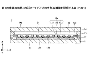
図1を参照するに、ヒートパイプ1は、金属層11〜14の4層が積層された構造を有する全方位型のヒートパイプである。金属層11〜14は、例えば、熱伝導性に優れた銅からなり、固相接合等により互いに直接接合されている。金属層11〜14の各々の厚さは、例えば、50μm〜200μm程度とすることができる。なお、金属層11〜14の材料は銅に限定されず、ステンレスやアルミニウム、マグネシウム合金等の熱伝導性が高い材料から形成してもよい。ヒートパイプ1の平面形状(金属層14の上面14aの法線方向から視た形状)は、ここでは一例として矩形状とする。
With reference to FIG. 1, the
なお、図1において、金属層11〜14の積層方向(厚さ方向)をZ方向、金属層14の上面14aの一辺に平行な方向をX方向、金属層14の上面14a内においてX方向と直交する方向をY方向としている(以降の図も同様)。又、本実施の形態では、便宜上、ヒートパイプ1の金属層14側を上側又は一方の側、金属層11側を下側又は他方の側とする。また、各部位の金属層14側の面を上面又は一方の面、金属層11側の面を下面又は他方の面とする。
In FIG. 1, the stacking direction (thickness direction) of the
ヒートパイプ1において、1層目(他方の最外層)の金属層11及び4層目(一方の最外層)の金属層14は、孔や溝は形成されていないベタ状の金属層である。
In the
金属層12は、金属層11の上面の上に積層されている。2層目の金属層12には、金属層13側(金属層12の上面側)からZ方向の略中央部に向かって窪む有底孔121と金属層11側(金属層12の下面側)からZ方向の略中央部に向かって窪む有底孔122とがそれぞれ複数個配置されている。又、有底孔121と有底孔122が部分的に連通した細孔123が配置されている。
The
金属層12は、有底孔121及び有底孔122、細孔123により構成される、Z方向に貫通した貫通孔12xを有している。
The
複数個の有底孔121は、行列状に配置されている。複数個の有底孔121は、例えば、X方向に所定間隔で配置された行と、Y方向に所定間隔で配置された列とを備えている。但し、行は必ずしもX方向に沿っている必要はなく、列は必ずしもY方向に沿っている必要はない。
The plurality of bottomed
又、行と列は必ずしも直交している必要はなく、例えば、行に対して列が斜めに設けられ、複数個の有底孔121が配置された領域の平面形状が全体として平行四辺形状であってもよい。又、各行及び各列に含まれる有底孔121の個数は同一でなくてもよく、例えば、複数個の有底孔121が配置された領域の平面形状が全体として台形状であってもよい。又、複数個の有底孔121は、千鳥状に配置されてもよい。
Further, the rows and columns do not necessarily have to be orthogonal to each other. For example, the planar shape of the region where the columns are provided diagonally with respect to the rows and a plurality of bottomed
有底孔122は、各々の有底孔121に対応して1つずつ設けられている。対応する有底孔121と有底孔122とは平面視において重複するように配置され、底面同士が部分的に連通して、細孔123が形成されている。すなわち、複数個の有底孔122は、複数個の有底孔121に対応して行列状に配置されており、平面視において重複する有底孔121と有底孔122とは底面同士が接してZ方向に連通している。但し、有底孔121と有底孔122とは、底面同士が細孔123を介して連通できるように配置されていれば、必ずしも平面視において完全に重複するように配置されていなくても構わない。
One bottomed
各々の有底孔121は、互いに離間して配置されている。つまり、X方向及びY方向に隣接する有底孔121同士は、連通していない。一方、X方向及びY方向に隣接する有底孔122は、側面同士が細孔125を介してX方向及びY方向に部分的に連通している。つまり、行列状に配置された全ての有底孔122が細孔125を介して連通している。
The bottomed
有底孔121の金属層12の上面側に開口する部分の面積は、有底孔122の金属層12の下面側に開口する部分の面積よりも小さい。有底孔121は、例えば、略半球状に形成されており、平面形状が円形である。この場合、有底孔121の金属層13側に開口する部分の直径φ1は、例えば、25μm程度とすることができる。
The area of the portion of the bottomed
有底孔122は、例えば、略半球状に形成されており、平面形状が円形である。この場合、有底孔122の金属層12の下面側に開口する部分の直径φ2は、有底孔121の金属層12の上面側に開口する部分の直径φ1よりも大きく、例えば、50μm程度とすることができる。
The bottomed
有底孔121と有底孔122とが連通する位置(細孔123の位置)は、金属層12の厚さ方向の中央よりも金属層12の上面側であり、例えば、D1:D2を3:7程度とすることができる。細孔123の直径φ3は、有底孔121の直径φ1及び有底孔122の直径φ2よりも小さく、例えば、15μm程度とすることができる。
The position where the bottomed
但し、有底孔121及び122の平面形状は円形には限定されず、楕円形や多角形等の任意の形状として構わない。又、有底孔121は略半球状には限定されず、細孔123側から金属層12の上面側に向かって内壁が拡幅する任意のテーパ形状として構わない。同様に、有底孔122は略半球状には限定されず、細孔123側から金属層12の下面側に向かって内壁が拡幅する任意のテーパ形状として構わない。
However, the planar shape of the bottomed
細孔125のX方向の幅W1、Y方向の幅W2、及びZ方向の高さH1は、各々有底孔122の直径φ2よりも小さい。細孔125のX方向の幅W1は、例えば、20μm程度とすることができる。細孔125のY方向の幅W2は、例えば、20μm程度とすることができる。細孔125のZ方向の高さH1は、例えば、10μm程度とすることができる。
The width W 1 in the X direction, the width W 2 in the Y direction, and the height H 1 in the Z direction of the
金属層13は、金属層12の上面上に積層されている。3層目の金属層13は、行列状に配置された貫通孔12xを露出する貫通孔13xを有し、枠状に形成されている。金属層14は、金属層13により形成された枠部に蓋をするように、金属層13上に積層されている。
The
図2は、第1の実施の形態に係るヒートパイプの各部の機能を説明する図(その1)であり、図1(a)に対応する断面を示している。 FIG. 2 is a diagram (No. 1) for explaining the functions of each part of the heat pipe according to the first embodiment, and shows a cross section corresponding to FIG. 1 (a).
図2に示すように、ヒートパイプ1において、金属層11及び金属層14は、外壁となる層になる。又、ヒートパイプ1において、枠状に形成された金属層13は、蒸気層になる。具体的には、金属層13(蒸気層)は、金属層13の貫通孔13x内において、金属層12の上面及び金属層14の下面で囲まれた気相部21を有している。気相部21は、作動流体Cが気化した蒸気Cvを高温側から低温側に移動させる領域である。
As shown in FIG. 2, in the
又、ヒートパイプ1において、金属層12は、液層になる。具体的には、金属層12(液層)は、液体流路部22と通気部23を有している。液体流路部22は、金属層12において、X方向及びY方向に連通する有底孔122から構成されている。液体流路部22(有底孔122)は、低温側で液化した作動流体Cを高温側に移動させる領域である。
Further, in the
又、通気部23は、金属層12において、有底孔122と連通する各々の有底孔121及び細孔123から構成されている。通気部23は、気相部21と液体流路部22を仕切ると共に、気相部21で発生した作動流体Cを液体流路部22へ移動させる領域である。
Further, the
液体流路部22は、初期状態において(ヒートパイプ1が発熱部品と接していない状態)作動流体Cで満たされている。作動流体Cの種類は特に限定されないが、蒸発潜熱によって発熱部品を効率的に冷却するために、蒸気圧が高く、かつ蒸発潜熱が大きい流体を使用することが好ましい。そのような流体としては、例えば、アンモニア、水、フロン、アルコール、及びアセトンを挙げることができる。
The liquid
図3は、第1の実施の形態に係るヒートパイプの各部の機能を説明する図(その2)であり、図3(b)は平面図、図3(a)は図3(b)のB−B線に沿う断面図である。 FIG. 3 is a diagram (No. 2) for explaining the functions of each part of the heat pipe according to the first embodiment, FIG. 3 (b) is a plan view, and FIG. 3 (a) is FIG. 3 (b). It is sectional drawing which follows the line BB.
図3に示すように、ヒートパイプ1では、金属層14の上面14aの法線方向から視て貫通孔12x(有底孔121及び122、細孔123)が均等に配置されている。そのため、金属層11の外面の任意の位置に半導体装置等の発熱部品を配置することができ、発熱部品を配置した位置が発熱部となる。図3では、一例として、金属層11の左下を発熱部H(蒸発部)としている。
As shown in FIG. 3, in the
図3において、発熱部H近傍の金属層11及び12の温度が上昇すると、発熱部H近傍の液体流路部22内の作動流体Cが気化(蒸発)して蒸気Cvが生成される。生成された蒸気Cvは、通気部23を介して気相部21に移動して気相部21の全体に広がる。発熱部Hから離れた個所が凝縮部Gとなり、蒸気Cvは凝縮部Gにおいて液化する。
In FIG. 3, when the temperatures of the metal layers 11 and 12 near the heat generating portion H rise, the working fluid C in the liquid
これにより、発熱部Hで発生した熱が凝縮部Gに移動して放熱される。凝縮部Gで液化した作動流体Cは、細孔123の毛細管力により通気部23を通って液体流路部22に吸い込まれる。液体流路部22に吸い込まれた作動流体Cは、細孔125の毛細管力により液体流路部22を通って作動流体Cの不足している個所、すなわち発熱部Hに移動する。以降、同様に蒸発と凝縮のサイクルを繰り返すことにより、発熱部Hの温度上昇が抑制される。
As a result, the heat generated in the heat generating portion H moves to the condensing portion G and is dissipated. The working fluid C liquefied in the condensing portion G is sucked into the liquid
[第1の実施の形態に係るヒートパイプの製造方法]
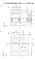
次に、第1の実施の形態に係るヒートパイプの製造方法について説明する。図4は、第1の実施の形態に係るヒートパイプの製造工程を例示する図であり、図1(a)に対応する断面を示している。
[Method for manufacturing a heat pipe according to the first embodiment]
Next, the method for manufacturing the heat pipe according to the first embodiment will be described. FIG. 4 is a diagram illustrating a heat pipe manufacturing process according to the first embodiment, and shows a cross section corresponding to FIG. 1 (a).
まず、図4(a)に示す工程では、金属シート120を準備し、金属シート120の上面に開口部310xを備えたレジスト層310を形成し、金属シート120の下面に開口部320xを備えたレジスト層320を形成する。開口部310xは、図1(b)に示す有底孔121に対応する位置の金属シート120の上面を露出するように形成する。又、開口部320xは、図1(b)に示す有底孔122に対応する位置の金属シート120の下面を露出するように形成する。
First, in the step shown in FIG. 4A, the
金属シート120は、最終的に金属層12となる部材であり、例えば、銅、ステンレス、アルミニウム、マグネシウム合金等から形成することができる。金属シート120の厚さは、例えば、50μm〜200μm程度とすることができる。レジスト層310及び320としては、例えば、感光性のドライフィルムレジスト等を用いることができる。開口部310x及び320xは、例えば、レジスト層310及び320を露光及び現像して形成することができる。
The
次に、図4(b)に示す工程では、開口部310x内に露出する金属シート120を金属シート120の上面側からハーフエッチングすると共に、開口部320x内に露出する金属シート120を金属シート120の下面側からハーフエッチングする。これにより、金属シート120の上面側に有底孔121が形成され、下面側に有底孔122が形成される。又、有底孔121及び有底孔122の底面同士がZ方向に部分的に連通し細孔123が形成され、有底孔121及び有底孔122、細孔123からなる貫通孔12xが形成される。又、X方向及びY方向に隣接する有底孔122は、側面同士がX方向及びY方向に部分的に連通し、細孔125が形成される。金属シート120のハーフエッチングには、例えば、塩化第二鉄溶液を用いることができる。その後、レジスト層310及び320を剥離液により剥離することで、貫通孔12xが行列状に配置された金属層12が完成する。
Next, in the step shown in FIG. 4B, the
次に、図4(c)に示す工程では、貫通孔13xを有する枠状の金属層13を形成する。金属層13は、金属シートを準備し、金属シートの不要部をエッチングで除去することで形成できる。或いは、金属層13は、金属シートを準備し、金属シートの不要部をプレス加工やレーザ加工により除去することで形成してもよい。
Next, in the step shown in FIG. 4C, a frame-shaped
次に、図4(d)に示す工程では、孔や溝が形成されていないベタ状の金属層11及び14を準備する。そして、金属層11、12、13、及び14を順次積層し、加圧及び加熱により固相接合を行う。これにより、隣接する金属層同士が直接接合され、気相部21、液体流路部22、及び通気部23を備えたヒートパイプ1が完成する。その後、真空ポンプ等を用いて液体流路部22内を排気した後、図示しない注入口から液体流路部22内に作動流体Cを注入し、その後注入口を封止する。
Next, in the step shown in FIG. 4D,
ここで、固相接合とは、接合対象物同士を溶融させることなく固相(固体)状態のまま加熱して軟化させ、更に加圧して塑性変形を与えて接合する方法である。なお、固相接合によって隣接する金属層同士を良好に接合できるように、金属層11〜14の全ての材料を同一にすることが好ましい。 Here, the solid-phase bonding is a method in which objects to be bonded are heated and softened in a solid-phase (solid) state without being melted, and further pressurized to give plastic deformation for bonding. It is preferable that all the materials of the metal layers 11 to 14 are the same so that the adjacent metal layers can be satisfactorily bonded by solid phase bonding.
このように、ヒートパイプ1では、蒸気が通る気相部21と作動流体が通る液体流路部22とが分かれている。そのため、発熱部H(蒸発部)側からの蒸気Cvの拡散と、凝縮部G側で凝縮した作動流体Cの戻りが別の層となり、互いにぶつかることがない。その結果、蒸発と凝縮がサイクルとして作動し、放熱性を向上することができる。
Thus, the
又、ヒートパイプ1では、金属層14の上面14aの法線方向から視て貫通孔12x(有底孔121及び122、細孔123)が均等に配置されている。そのため、発熱部H(蒸発部)と凝縮部Gの区分けがなく、金属層11の外面の任意の位置に半導体装置等の発熱部品を配置して発熱部Hとすることができる。そして、発熱部H付近で蒸発した蒸気Cvは全方位へ広がり、温度の低い部分が凝縮部Gとなって蒸気が凝縮する。このような構造により、全方位に均等な熱拡散性能を有し、姿勢依存性がないヒートパイプを実現できる。
Further, in the
又、ヒートパイプ1では、1つの金属層に液体流路部22及び通気部23を形成している。そのため、ヒートパイプ1を薄型化することが可能となる。
Further, in the
〈第1の実施の形態の変形例1〉
第1の実施の形態の変形例1では、支柱を設ける例を示す。なお、第1の実施の形態の変形例1において、既に説明した実施の形態と同一構成部についての説明は省略する場合がある。
<
In the first modification of the first embodiment, an example in which a support column is provided is shown. In the first modification of the first embodiment, the description of the same components as those of the above-described embodiment may be omitted.
図5は、第1の実施の形態の変形例1に係るヒートパイプを例示する図であり、図5(b)は平面図、図5(a)は図5(b)のA−A線に沿う断面図である。 5A and 5B are views illustrating the heat pipe according to the first modification of the first embodiment, FIG. 5B is a plan view, FIG. 5A is a line AA of FIG. 5B. It is a cross-sectional view along.
図5を参照するに、ヒートパイプ1Aは、枠状に形成された金属層13の内側に支柱15が設けられている。図5の例では、支柱15が4本設けられているが、支柱15は1〜3本又は5本以上設けても構わない。
With reference to FIG. 5, the
このように、枠状に形成された金属層13の内側に支柱15を設けることで、ヒートパイプ1Aを製造する際に、図4(d)の工程で金属層11、12、13、及び14を順次積層して加圧するときに金属層14が潰れることを防止できる。又、ヒートパイプ1Aが動作している際に、金属層14が変形して気相部21が潰れることを防止できる。
By providing the
〈第1の実施の形態の変形例2〉
第1の実施の形態の変形例2では、1つの有底孔122に対して金属層12の上面側に複数の有底孔を設ける例を示す。なお、第1の実施の形態の変形例2において、既に説明した実施の形態と同一構成部についての説明は省略する場合がある。
<
In the second modification of the first embodiment, an example is shown in which a plurality of bottomed holes are provided on the upper surface side of the
図6は、第1の実施の形態の変形例2に係るヒートパイプを例示する図であり、図6(b)は部分平面図、図6(a)は図6(b)のC−C線に沿う部分断面図である。 6A and 6B are views illustrating the heat pipe according to the second modification of the first embodiment, FIG. 6B is a partial plan view, and FIG. 6A is a CC of FIG. 6B. It is a partial sectional view along the line.
図6に示すヒートパイプ1Bにおいて、2層目の金属層12には、金属層12の上面側からZ方向の略中央部に向かって窪む有底孔121a及び121bと金属層12の下面側からZ方向の略中央部に向かって窪む有底孔122が形成されている。また、有底孔121a及び121bと有底孔122が部分的に連通した細孔123a及び123bが配置されている。
In the
金属層12は、有底孔121a及び121bと有底孔122、細孔123a及び123bにより構成される、Z方向に貫通した貫通孔12yを有している。
The
すなわち、各々の貫通孔12yにおいて、1つの有底孔122に対して有底孔121a及び121bが設けられている。対応する有底孔121a及び121bと有底孔122とは平面視において重複するように配置されている。そして、有底孔121aと有底孔122の底面同士が部分的に連通して細孔123aが形成されている。又、有底孔121bと有底孔122の底面同士が部分的に連通して細孔123bが形成されている。
That is, in each through
X方向において隣接する有底孔121aと有底孔121bとは、互いに離間して配置されている。又、Y方向において隣接する有底孔121a同士、及びY方向において隣接する有底孔121b同士は、互いに離間して配置されている。
The bottomed
有底孔121a及び121bの金属層12の上面側に開口する部分の面積は、有底孔122の金属層12の下面側に開口する部分の面積よりも小さい。有底孔121a及び121bは、例えば、略半球状に形成されており、平面形状が円形である。有底孔121a及び121bと有底孔122とが連通する位置(細孔123a及び123bの位置)は、金属層12の厚さ方向の中央よりも金属層12の上面側である。
The area of the portion of the bottomed
但し、有底孔121a及び121bの平面形状は円形には限定されず、楕円形や多角形等の任意の形状として構わない。又、有底孔121a及び121bは略半球状には限定されず、細孔123a及び123b側から金属層12の上面側に向かって内壁が拡幅する任意のテーパ形状として構わない。
However, the planar shape of the bottomed
このように、各々の貫通孔12yにおいて、1つの有底孔122に対して金属層12の上面側に2つの有底孔121a及び121bを設けても構わない。この場合、細孔123a及び123bの大きさを第1の実施の形態の細孔123の大きさよりも小さくできるため、作動流体Cを気相部21から液体流路部22に吸い込む際の毛細管力を大きくすることができる。
In this way, in each through
なお、1つの有底孔122に対して金属層12の上面側に3つ以上の有底孔を設けても構わない。又、1つの有底孔122に対して金属層12の上面側に設けられる複数の有底孔を各々異なる大きさ(例えば、異なる径)にしても構わない。
It should be noted that three or more bottomed holes may be provided on the upper surface side of the
〈第1の実施の形態の変形例3〉
第1の実施の形態の変形例3では、有底孔の密度を変える例を示す。なお、第1の実施の形態の変形例3において、既に説明した実施の形態と同一構成部についての説明は省略する場合がある。
<
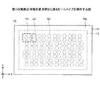
図7は、第1の実施の形態の変形例3に係るヒートパイプを例示する図であり、図1(b)に対応する平面図である。但し、図7では、金属層12において有底孔122に対して金属層12の上面側に設けられる有底孔121のみを図示しており、有底孔122や細孔123の図示は省略している。
FIG. 7 is a view illustrating the heat pipe according to the modified example 3 of the first embodiment, and is a plan view corresponding to FIG. 1 (b). However, in FIG. 7, only the bottomed
図7に示すヒートパイプ1Cでは、有底孔121が高密度に配置された高密度領域Hdと、有底孔121が低密度に配置された低密度領域LdとがX方向及びY方向に交互に配置されている。高密度領域Hdでは、例えば、1つの有底孔122に対して複数の有底孔121を設けることができる。
In the heat pipe 1C shown in FIG. 7, the high-density region Hd in which the bottomed
ヒートパイプ1Cのように、有底孔121の密度は必ずしも均一とする必要はなく、高密度領域Hdと低密度領域Ldを有しても構わない。この場合は、発熱部からの熱拡散効率向上の効果が期待できる。又、作動流体の気化効率や、液化した作動流体を液層に戻す効率が向上する効果が期待できる。
Like the heat pipe 1C, the density of the bottomed
なお、密度の異なる領域は2種類には限定されず、3種類以上の密度の異なる領域を有しても構わない。 The regions having different densities are not limited to two types, and three or more regions having different densities may be included.
〈第1の実施の形態の変形例4〉
第1の実施の形態の変形例4では、有底孔の大きさを変える例を示す。なお、第1の実施の形態の変形例4において、既に説明した実施の形態と同一構成部についての説明は省略する場合がある。
<Modification 4 of the first embodiment>
In the modified example 4 of the first embodiment, an example of changing the size of the bottomed hole is shown. In the modified example 4 of the first embodiment, the description of the same component as that of the above-described embodiment may be omitted.
図8は、第1の実施の形態の変形例4に係るヒートパイプを例示する図であり、図1(b)に対応する平面図である。但し、図8では、金属層12において有底孔122に対して金属層13側に設けられる有底孔121c及び121dのみを図示しており、有底孔122や細孔123の図示は省略している。
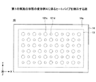
FIG. 8 is a view illustrating the heat pipe according to the modified example 4 of the first embodiment, and is a plan view corresponding to FIG. 1 (b). However, in FIG. 8, only the bottomed
図8に示すヒートパイプ1Dでは、金属層12の上面側に開口する部分の面積の大きい(例えば、大径の)有底孔121cと、金属層12の上面側に開口する部分の面積の小さい(例えば、小径の)有底孔121dとがX方向及びY方向に交互に配置されている。有底孔121c及び121dは、例えば、有底孔121と同様に、略半球状等に形成することができる。
In the heat pipe 1D shown in FIG. 8, the area of the portion opened on the upper surface side of the
ヒートパイプ1Dのように、金属層12の上面側に開口する各々の有底孔の開口する部分の面積は必ずしも同一とする必要はなく、開口する部分の面積の大きい有底孔121cと開口する部分の面積の小さい有底孔121dを有しても構わない。この場合は、作動流体の気化効率や、液化した作動流体を液層に戻す効率が向上する効果が期待できる。
Like the heat pipe 1D, the area of the opening portion of each bottomed hole opened on the upper surface side of the
なお、金属層13側に開口する各々の有底孔の開口する部分の面積は2種類には限定されず、3種類以上としても構わない。
The area of each bottomed hole opened on the
〈第2の実施の形態〉
第2の実施の形態では、ヒートパイプを更に薄型化する例を示す。なお、第2の実施の形態において、既に説明した実施の形態と同一構成部についての説明は省略する場合がある。
<Second Embodiment>
In the second embodiment, an example of further thinning the heat pipe is shown. In the second embodiment, the description of the same components as those in the above-described embodiment may be omitted.
[第2の実施の形態に係るヒートパイプの構造]
まず、第2の実施の形態に係るヒートパイプの構造について説明する。図9は、第2の実施の形態に係るヒートパイプを例示する図であり、図9(b)は平面図、図9(a)は図9(b)のA−A線に沿う断面図である。
[Structure of heat pipe according to the second embodiment]
First, the structure of the heat pipe according to the second embodiment will be described. 9A and 9B are views illustrating the heat pipe according to the second embodiment, FIG. 9B is a plan view, and FIG. 9A is a sectional view taken along the line AA of FIG. 9B. Is.
図9を参照するに、ヒートパイプ2は、金属層13及び14が1層の金属層25に置換された点がヒートパイプ1(図1参照)と相違し、その他の点はヒートパイプ1と同様である。すなわち、ヒートパイプ2は、金属層11、12、及び25の3層が積層された構造を有する全方位型のヒートパイプである。金属層11、12、及び25は、例えば銅、ステンレス、アルミニウム、マグネシウム合金等からなり、固相接合等により互いに直接接合されている。
With reference to FIG. 9, the
金属層25は、上面25a及び下面25bを有する矩形状の平板部251と、平板部251の下面25bの外周部から金属層12側に突起する側壁部252とを備えている。金属層25は、平板部251と側壁部252とが一体に形成され、凹型の形状からなる。側壁部252は、行列状に配置された貫通孔12xを露出する開口部25xを有し、平板部251の下面25bの外周部に枠状に形成されている。金属層25の側壁部252の下面は、金属層12の上面の外周部と直接接合されている。
The
金属層25の全体の厚さT1は、例えば、50μm〜200μm程度とすることができる。金属層25の全体の厚さT1は、例えば、金属層11及び12の厚さと同一としてもよい。金属層25の側壁部252の厚さT2は、例えば、厚さT1の半分程度とすることができる。
The total thickness T 1 of the
金属層25の側壁部252は蒸気層となり、側壁部252の開口部25x内において、金属層12の上面及び金属層25の下面25bで囲まれた気相部21(図2参照)を有している。気相部21は、作動流体Cが気化した蒸気Cvを高温側から低温側に移動させる領域である。
The
[第2の実施の形態に係るヒートパイプの製造方法]
次に、第2の実施の形態に係るヒートパイプの製造方法について説明する。図10は、第2の実施の形態に係るヒートパイプの製造工程を例示する図であり、図9(a)に対応する断面を示している。
[Method for manufacturing a heat pipe according to the second embodiment]
Next, a method for manufacturing the heat pipe according to the second embodiment will be described. FIG. 10 is a diagram illustrating a heat pipe manufacturing process according to the second embodiment, and shows a cross section corresponding to FIG. 9A.
まず、第1の実施の形態の図4(a)、及び図4(b)の工程を実行し、金属層12を作製する。
First, the steps of FIGS. 4 (a) and 4 (b) of the first embodiment are executed to prepare the
次に、図10(a)に示す工程では、金属シート250を準備し、金属シート250の上面の全体にベタ状のレジスト層330を形成し、金属シート250の下面に矩形状の開口部340xを備えた枠状のレジスト層340を形成する。レジスト層340は、側壁部252を形成したい領域を被覆するように形成する。
Next, in the step shown in FIG. 10A, the
金属シート250は、最終的に金属層25となる部材であり、例えば、銅、ステンレス、アルミニウム、マグネシウム合金等から形成することができる。金属シート250の厚さは、例えば、50μm〜200μm程度とすることができる。レジスト層330及び340としては、例えば、感光性のドライフィルムレジスト等を用いることができる。開口部340xは、例えば、レジスト層340を露光及び現像して形成することができる。
The
次に、図10(b)に示す工程では、開口部340x内に露出する金属シート250を金属シート250の下面側からハーフエッチングして、中央側に有底の開口部25xを形成すると共に、外周側に開口部25xを囲む側壁部252を形成する。金属シート250のハーフエッチングには、例えば、塩化第二鉄溶液を用いることができる。その後、レジスト層330及び340を剥離液により剥離することで、平板部251の下面25bの外周部に開口部25xを囲む枠状の側壁部252を備えた金属層25が形成される。
Next, in the step shown in FIG. 10B, the
なお、図10(a)において、金属シート250の下面の全体にベタ状のレジスト層330を形成し、金属シート250の上面に矩形状の開口部340xを備えた枠状のレジスト層340を形成してもよい。この場合には、図10(b)において、開口部340x内に露出する金属シート250を金属シート250の上面側からハーフエッチングして開口部25xを形成する。
In FIG. 10A, a solid resist
次に、孔や溝が形成されていないベタ状の金属層11を準備し、図4(d)の工程と同様にして、金属層11、12、及び25を順次積層し、加圧及び加熱により固相接合を行う。これにより、隣接する金属層同士が直接接合され、気相部21、液体流路部22、及び通気部23を備えたヒートパイプ2が完成する。その後、真空ポンプ等を用いて液体流路部22内を排気した後、図示しない注入口から液体流路部22内に作動流体Cを注入し、その後注入口を封止する。なお、固相接合によって隣接する金属層同士を良好に接合できるように、金属層11、12、及び25の全ての材料を同一にすることが好ましい。
Next, a
このように、ヒートパイプ1における金属層13及び14を1層の金属層25に置き換えてヒートパイプ2としてもよい。ヒートパイプ2では、曲げ加工や成型加工を用いずにハーフエッチングで有底孔や開口部を形成するため、薄型化が容易である。ヒートパイプ2において、例えば、金属層11、12、及び25を何れも50μmの厚さで形成すれば、総厚が150μmの薄型のヒートパイプを実現することができる。その他の効果については、第1の実施の形態に示した通りである。
In this way, the metal layers 13 and 14 in the
〈第2の実施の形態の変形例1〉
第2の実施の形態の変形例1では、支柱を設ける例を示す。なお、第2の実施の形態の変形例1において、既に説明した実施の形態と同一構成部についての説明は省略する場合がある。
<
In the first modification of the second embodiment, an example in which a support column is provided is shown. In the first modification of the second embodiment, the description of the same components as those of the above-described embodiment may be omitted.
図11は、第2の実施の形態の変形例1に係るヒートパイプを例示する図であり、図11(b)は平面図、図11(a)は図11(b)のA−A線に沿う断面図である。 11A and 11B are views illustrating the heat pipe according to the first modification of the second embodiment, FIG. 11B is a plan view, and FIG. 11A is a line AA of FIG. 11B. It is a cross-sectional view along.
図11を参照するに、ヒートパイプ2Aは、金属層25が金属層25Aに置換された点がヒートパイプ2(図9参照)と相違し、その他の点はヒートパイプ2と同様である。すなわち、ヒートパイプ2Aは、金属層11、12、及び25Aの3層が積層された構造を有する全方位型のヒートパイプである。金属層11、12、及び25Aは、例えば銅、ステンレス、アルミニウム、マグネシウム合金等からなり、固相接合等により互いに直接接合されている。
Referring to FIG. 11, the
金属層25Aは、上面25a及び下面25bを有する矩形状の平板部251と、平板部251の下面25bの外周部から金属層12側に突起する側壁部252と、側壁部252の内側に設けられた支柱253とを備えている。平板部251と側壁部252と支柱253とは一体に形成されている。側壁部252は、行列状に配置された貫通孔12xを露出する開口部25xを有し、平板部251の下面25bの外周部に枠状に形成されている。支柱253は、開口部25x内に露出する平板部251の下面25bから金属層12側に突起している。図11の例では、支柱253が4本設けられているが、支柱253は1〜3本又は5本以上設けても構わない。金属層25Aの側壁部252の下面は、金属層12の上面の外周部と直接接合されている。又、金属層25Aの各々の支柱253の下面は、金属層12の上面の所定位置と直接接合されている。
The
金属層25Aを作製するには、例えば、金属シートを準備し、金属シートの上面の全体にベタ状の第1レジスト層を形成し、金属シートの下面の外周部(側壁部252となる部分)及び支柱253の形成部に第2レジスト層を選択的に形成する。そして、金属シートの下面側の第2レジスト層から露出する部分をハーフエッチングする。これにより、中央側に有底の開口部25xが形成されると共に、外周側に開口部25xを囲む側壁部252が形成され、開口部25x内に支柱253が形成される。金属層25Aのハーフエッチングには、例えば、塩化第二鉄溶液を用いることができる。その後、第1及び第2レジスト層を剥離液により剥離することで、平板部251と側壁部252と支柱253とが一体に形成された金属層25Aが完成する。
To produce the
このように、金属層25Aの枠状に形成された側壁部252の内側に支柱253を設けることで、ヒートパイプ2Aを製造する際に、図4(d)と同様の工程で金属層11、12、及び25Aを順次積層して加圧するときに金属層25Aが潰れることを防止できる。又、ヒートパイプ2Aが動作している際に、金属層25Aが変形して気相部21が潰れることを防止できる。その他の効果については、第1の実施の形態及び第2の実施の形態に示した通りである。
By providing the
以上、好ましい実施の形態について詳説したが、上述した実施の形態に制限されることはなく、特許請求の範囲に記載された範囲を逸脱することなく、上述した実施の形態に種々の変形及び置換を加えることができる。 Although the preferred embodiment has been described in detail above, it is not limited to the above-described embodiment, and various modifications and substitutions are made to the above-described embodiment without departing from the scope of claims. Can be added.
例えば、第1の実施の形態及び変形例1〜4は、適宜組み合わせて実施することができる。又、第2の実施の形態及び変形例1と、第1の実施の形態の変形例2〜4は、適宜組み合わせて実施することができる。 For example, the first embodiment and the modified examples 1 to 4 can be carried out in appropriate combinations. Further, the second embodiment and the modified example 1 and the modified examples 2 to 4 of the first embodiment can be carried out in an appropriate combination.
1、1A、1B、1C、1D ヒートパイプ
11、12、13、14、25、25A 金属層
12x、12y 貫通孔
13x 貫通孔
14a 金属層14の上面
15 支柱
21 気相部
22 液体流路部
23 通気部
25a 金属層25及び25Aの上面
25b 金属層25及び25Aの下面
25x 開口部
121、121a、121b、121c、121d、122 有底孔
123、123a、123b、125 細孔
251 平板部
252 側壁部
253 支柱
1,1A, 1B, 1C,
Claims (13)
前記液層は、一方の面側から窪み、互いに離間して配置された複数の第1の有底孔と、他方の面側から窪む複数の第2の有底孔と、前記第1の有底孔と前記第2の有底孔とが部分的に連通して形成された第1の細孔と、隣接する前記第2の有底孔の側面が部分的に連通して形成された第2の細孔と、を備えた第1金属層からなり、
前記蒸気層は、前記第1金属層の一方の面上に、前記複数の第1の有底孔を露出するように枠状に形成された第2金属層からなることを特徴とするヒートパイプ。 A heat pipe comprising a steam layer for moving vapor vaporized by the working fluid and a liquid layer for moving the working fluid liquefied by the steam.
The liquid layer has a plurality of first bottomed holes recessed from one surface side and arranged apart from each other, a plurality of second bottomed holes recessed from the other surface side, and the first bottomed hole. The first pore formed by partially communicating the bottomed hole and the second bottomed hole and the side surface of the adjacent second bottomed hole were formed by partially communicating with each other. Consists of a first metal layer with a second pore and
The steam layer is a heat pipe comprising a second metal layer formed in a frame shape so as to expose the plurality of first bottomed holes on one surface of the first metal layer. ..
前記液層は、一方の面側から窪み、互いに離間して配置された複数の第1の有底孔と、他方の面側から窪む複数の第2の有底孔と、前記第1の有底孔と前記第2の有底孔とが部分的に連通して形成された第1の細孔と、隣接する前記第2の有底孔の側面が部分的に連通して形成された第2の細孔と、を備えた第1金属層からなり、
前記蒸気層は、前記第1金属層の一方の面上に形成された凹型の形状の第2金属層からなることを特徴とするヒートパイプ。 A heat pipe comprising a steam layer for moving vapor vaporized by the working fluid and a liquid layer for moving the working fluid liquefied by the steam.
The liquid layer has a plurality of first bottomed holes recessed from one surface side and arranged apart from each other, a plurality of second bottomed holes recessed from the other surface side, and the first bottomed hole. The first pore formed by partially communicating the bottomed hole and the second bottomed hole and the side surface of the adjacent second bottomed hole were formed by partially communicating with each other. Consists of a first metal layer with a second pore and
The heat pipe is characterized in that the steam layer is composed of a concave-shaped second metal layer formed on one surface of the first metal layer.
前記第2の有底孔は、前記第1の細孔側から前記他方の面側に向かって内壁が拡幅することを特徴とする請求項1乃至3の何れか一項に記載のヒートパイプ。 The inner wall of the first bottomed hole widens from the first pore side toward the one surface side.
The heat pipe according to any one of claims 1 to 3, wherein the second bottomed hole widens the inner wall from the first pore side toward the other surface side.
前記第1金属層を形成する工程は、
第1の金属シートを一方の面側からハーフエッチングして、第1の有底孔を複数形成し、前記第1の金属シートを他方の面側からハーフエッチングし、第2の有底孔を複数形成すると共に、前記第1の有底孔と部分的に連通する第1の細孔と、隣接する前記第2の有底孔の側面が部分的に連通して形成された第2の細孔を形成する工程を有し、
前記第2金属層を形成する工程は、
第2の金属シートを厚さ方向に貫通する貫通孔を形成する工程を有することを特徴とするヒートパイプの製造方法。 A step of forming a second metal layer forming a vapor layer for moving vapor vaporized by the working fluid, and a step of forming a first metal layer forming a liquid layer for moving the working fluid liquefied by the vapor. A method for manufacturing a heat pipe, comprising a step of joining the second metal layer on one surface of the first metal layer.
The step of forming the first metal layer is
The first metal sheet is half-etched from one surface side to form a plurality of first bottomed holes, the first metal sheet is half-etched from the other surface side, and the second bottomed holes are formed. A second fine particle formed by forming a plurality of the first pores and partially communicating with the first bottomed hole and partially communicating with the side surface of the adjacent second bottomed hole. Has a process of forming holes,
The step of forming the second metal layer is
A method for manufacturing a heat pipe, which comprises a step of forming a through hole penetrating a second metal sheet in the thickness direction.
前記第1金属層を形成する工程は、
第1の金属シートを一方の面側からハーフエッチングして、第1の有底孔を複数形成し、前記第1の金属シートを他方の面側からハーフエッチングし、第2の有底孔を複数形成すると共に、前記第1の有底孔と部分的に連通する第1の細孔と、隣接する前記第2の有底孔の側面が部分的に連通して形成された第2の細孔を形成する工程を有し、
前記第2金属層を形成する工程は、
第2の金属シートを一方の面又は他方の面側からハーフエッチングして、中央側に有底の開口部を形成すると共に、外周側に前記開口部を囲む側壁部を形成する工程を有することを特徴とするヒートパイプの製造方法。 A step of forming a second metal layer provided with a side wall portion forming a vapor layer for moving vapor vaporized by the working fluid, and a first metal layer forming a liquid layer for moving the working fluid liquefied by the steam. A method for manufacturing a heat pipe, comprising a step of forming the first metal layer and a step of joining the second metal layer on one surface of the first metal layer.
The step of forming the first metal layer is
The first metal sheet is half-etched from one surface side to form a plurality of first bottomed holes, the first metal sheet is half-etched from the other surface side, and the second bottomed holes are formed. A second fine particle formed by forming a plurality of the first pores and partially communicating with the first bottomed hole and partially communicating with the side surface of the adjacent second bottomed hole. Has a process of forming holes,
The step of forming the second metal layer is
It has a step of half-etching the second metal sheet from one surface or the other surface side to form a bottomed opening on the center side and a side wall portion surrounding the opening on the outer peripheral side. A method for manufacturing a heat pipe.
前記第2の有底孔は、前記第1の細孔側から前記他方の面側に向かって内壁が拡幅することを特徴とする請求項9乃至11の何れか一項に記載のヒートパイプの製造方法。 The inner wall of the first bottomed hole widens from the first pore side toward the one surface side.
The heat pipe according to any one of claims 9 to 11, wherein the second bottomed hole widens the inner wall from the first pore side toward the other surface side. Production method.
Priority Applications (3)
| Application Number | Priority Date | Filing Date | Title |
|---|---|---|---|
| US15/807,797 US10352626B2 (en) | 2016-12-14 | 2017-11-09 | Heat pipe |
| CN201711180902.8A CN108225072B (en) | 2016-12-14 | 2017-11-23 | Heat pipe and method for manufacturing the same |
| US16/426,173 US11384993B2 (en) | 2016-12-14 | 2019-05-30 | Heat pipe |
Applications Claiming Priority (2)
| Application Number | Priority Date | Filing Date | Title |
|---|---|---|---|
| JP2016242730 | 2016-12-14 | ||
| JP2016242730 | 2016-12-14 |
Publications (3)
| Publication Number | Publication Date |
|---|---|
| JP2018096669A JP2018096669A (en) | 2018-06-21 |
| JP2018096669A5 JP2018096669A5 (en) | 2020-01-23 |
| JP6799503B2 true JP6799503B2 (en) | 2020-12-16 |
Family
ID=62632783
Family Applications (1)
| Application Number | Title | Priority Date | Filing Date |
|---|---|---|---|
| JP2017112587A Active JP6799503B2 (en) | 2016-12-14 | 2017-06-07 | Heat pipe and its manufacturing method |
Country Status (2)
| Country | Link |
|---|---|
| JP (1) | JP6799503B2 (en) |
| CN (1) | CN108225072B (en) |
Families Citing this family (11)
| Publication number | Priority date | Publication date | Assignee | Title |
|---|---|---|---|---|
| JP7137783B2 (en) * | 2017-08-24 | 2022-09-15 | 大日本印刷株式会社 | Wick sheet for vapor chamber, vapor chamber and method for manufacturing vapor chamber |
| JP6400240B1 (en) * | 2018-02-05 | 2018-10-03 | 新光電気工業株式会社 | Loop heat pipe and manufacturing method thereof |
| JP6943786B2 (en) | 2018-02-05 | 2021-10-06 | 新光電気工業株式会社 | Loop type heat pipe and its manufacturing method |
| JP7236825B2 (en) * | 2018-07-11 | 2023-03-10 | 新光電気工業株式会社 | Loop type heat pipe and its manufacturing method |
| JP7146524B2 (en) | 2018-08-13 | 2022-10-04 | 新光電気工業株式会社 | Loop type heat pipe and its manufacturing method |
| JP7197346B2 (en) * | 2018-12-19 | 2022-12-27 | 新光電気工業株式会社 | loop heat pipe |
| KR102640712B1 (en) * | 2019-03-11 | 2024-02-27 | 다이니폰 인사츠 가부시키가이샤 | Vapor chambers, electronic devices and sheets for vapor chambers |
| JP2021032539A (en) * | 2019-08-28 | 2021-03-01 | 京セラ株式会社 | Heat transport plate and manufacturing method for heat transport plate |
| KR102447793B1 (en) * | 2019-11-11 | 2022-09-27 | 주식회사 아모그린텍 | Sheet type heat pipe and manufacturing method thereof |
| WO2021208070A1 (en) * | 2020-04-17 | 2021-10-21 | 李克勤 | Laminated thin heat dissipation device and manufacturing method therefor |
| JP7422600B2 (en) * | 2020-04-17 | 2024-01-26 | 新光電気工業株式会社 | Loop type heat pipe and its manufacturing method |
Family Cites Families (15)
| Publication number | Priority date | Publication date | Assignee | Title |
|---|---|---|---|---|
| JP2001336888A (en) * | 2000-05-29 | 2001-12-07 | Fujikura Ltd | Laminated flat plate type heat pipe |
| US6843308B1 (en) * | 2000-12-01 | 2005-01-18 | Atmostat Etudes Et Recherches | Heat exchanger device using a two-phase active fluid, and a method of manufacturing such a device |
| TWI247873B (en) * | 2002-08-21 | 2006-01-21 | Samsung Electronics Co Ltd | Flat heat transferring device and method of fabricating the same |
| JP4306665B2 (en) * | 2005-09-27 | 2009-08-05 | パナソニック株式会社 | Sheet-like heat pipe and manufacturing method thereof |
| JP4557055B2 (en) * | 2008-06-25 | 2010-10-06 | ソニー株式会社 | Heat transport device and electronic equipment |
| JP2011080679A (en) * | 2009-10-07 | 2011-04-21 | Sony Corp | Heat transfer device and electronic equipment |
| JP5413735B2 (en) * | 2010-01-18 | 2014-02-12 | 日本モレックス株式会社 | Heat transport unit, electronic equipment |
| CN201715908U (en) * | 2010-06-07 | 2011-01-19 | 锘威科技(深圳)有限公司 | Integral sintered flat heat pipe |
| CN102175088A (en) * | 2011-03-16 | 2011-09-07 | 大连理工大学 | Silica-based unequal-width microchannel flat heat pipe and manufacture method thereof |
| CN102683305B (en) * | 2012-05-14 | 2014-12-10 | 西安交通大学 | Chip reinforced boiling heat transfer structure of multi-pore microcolumn variable camber molded surfaces |
| CN103123236B (en) * | 2012-10-21 | 2014-09-24 | 大连三维传热技术有限公司 | Hot plate of metal fiber felt liquid absorption cores |
| TWI513069B (en) * | 2013-05-21 | 2015-12-11 | Subtron Technology Co Ltd | Heat dissipation plate |
| JP6311279B2 (en) * | 2013-11-11 | 2018-04-18 | 大日本印刷株式会社 | Heat dissipation member, manufacturing method thereof, and structure using heat dissipation member |
| US9488418B2 (en) * | 2014-07-08 | 2016-11-08 | Chaun-Choung Technology Corp. | Heat plate structure |
| CN204651303U (en) * | 2015-05-25 | 2015-09-16 | 新乡市特美特换热设备有限公司 | A kind of electronic element radiating cold drawing |
-
2017
- 2017-06-07 JP JP2017112587A patent/JP6799503B2/en active Active
- 2017-11-23 CN CN201711180902.8A patent/CN108225072B/en active Active
Also Published As
| Publication number | Publication date |
|---|---|
| JP2018096669A (en) | 2018-06-21 |
| CN108225072B (en) | 2020-10-30 |
| CN108225072A (en) | 2018-06-29 |
Similar Documents
| Publication | Publication Date | Title |
|---|---|---|
| JP6799503B2 (en) | Heat pipe and its manufacturing method | |
| US11384993B2 (en) | Heat pipe | |
| US10704838B2 (en) | Loop heat pipe | |
| JP6886904B2 (en) | Loop type heat pipe, manufacturing method of loop type heat pipe, electronic equipment | |
| JP6889093B2 (en) | Heat pipe and its manufacturing method | |
| US20180142960A1 (en) | Loop heat pipe | |
| US11402158B2 (en) | Loop heat pipe | |
| JP6951267B2 (en) | Heat pipe and its manufacturing method | |
| JP2016142416A (en) | Loop heat pipe and process of manufacture of loop heat pipe | |
| JP2009024933A (en) | Thermal diffusion device and manufacturing method for it | |
| JP7305512B2 (en) | Loop type heat pipe and its manufacturing method | |
| JP6943786B2 (en) | Loop type heat pipe and its manufacturing method | |
| JP6413306B2 (en) | Heat pipe built-in frame plate and electronic equipment | |
| CN112033197B (en) | Temperature equalizing plate and manufacturing method thereof | |
| US11105562B2 (en) | Loop-type heat pipe | |
| JP2019207083A (en) | Loop type heat pipe and method of manufacturing the same | |
| JP6920115B2 (en) | Heat pipe and heat pipe manufacturing method | |
| CN110195988B (en) | Flat-plate loop heat pipe | |
| US20210131742A1 (en) | Loop heat pipe | |
| JP6863058B2 (en) | Heat pipes and electronic devices | |
| TWI773145B (en) | Vapor chamber | |
| JP3161474U (en) | Vapor chamber structure | |
| JP2024015913A (en) | Cooling device |
Legal Events
| Date | Code | Title | Description |
|---|---|---|---|
| A521 | Written amendment |
Free format text: JAPANESE INTERMEDIATE CODE: A523 Effective date: 20191202 |
|
| A621 | Written request for application examination |
Free format text: JAPANESE INTERMEDIATE CODE: A621 Effective date: 20191202 |
|
| A977 | Report on retrieval |
Free format text: JAPANESE INTERMEDIATE CODE: A971007 Effective date: 20201026 |
|
| TRDD | Decision of grant or rejection written | ||
| A01 | Written decision to grant a patent or to grant a registration (utility model) |
Free format text: JAPANESE INTERMEDIATE CODE: A01 Effective date: 20201104 |
|
| A61 | First payment of annual fees (during grant procedure) |
Free format text: JAPANESE INTERMEDIATE CODE: A61 Effective date: 20201120 |
|
| R150 | Certificate of patent or registration of utility model |
Ref document number: 6799503 Country of ref document: JP Free format text: JAPANESE INTERMEDIATE CODE: R150 |