JP6794440B2 - A device that characterizes the walls of blood vessels - Google Patents
A device that characterizes the walls of blood vessels Download PDFInfo
- Publication number
- JP6794440B2 JP6794440B2 JP2018518474A JP2018518474A JP6794440B2 JP 6794440 B2 JP6794440 B2 JP 6794440B2 JP 2018518474 A JP2018518474 A JP 2018518474A JP 2018518474 A JP2018518474 A JP 2018518474A JP 6794440 B2 JP6794440 B2 JP 6794440B2
- Authority
- JP
- Japan
- Prior art keywords
- blood vessel
- measurement signal
- blood
- instantaneous
- pressure measurement
- Prior art date
- Legal status (The legal status is an assumption and is not a legal conclusion. Google has not performed a legal analysis and makes no representation as to the accuracy of the status listed.)
- Active
Links
- 210000004204 blood vessel Anatomy 0.000 title claims description 93
- 206010002329 Aneurysm Diseases 0.000 claims description 78
- 238000005259 measurement Methods 0.000 claims description 67
- 238000009530 blood pressure measurement Methods 0.000 claims description 50
- 230000000541 pulsatile effect Effects 0.000 claims description 50
- 238000000034 method Methods 0.000 claims description 41
- 239000008280 blood Substances 0.000 claims description 32
- 210000004369 blood Anatomy 0.000 claims description 32
- 238000003384 imaging method Methods 0.000 claims description 28
- 230000000877 morphologic effect Effects 0.000 claims description 18
- 244000208734 Pisonia aculeata Species 0.000 claims description 6
- 210000001367 artery Anatomy 0.000 claims 1
- 230000017531 blood circulation Effects 0.000 description 46
- 230000002792 vascular Effects 0.000 description 36
- 230000036772 blood pressure Effects 0.000 description 20
- 238000011282 treatment Methods 0.000 description 15
- 239000012528 membrane Substances 0.000 description 11
- 239000002872 contrast media Substances 0.000 description 10
- 238000002583 angiography Methods 0.000 description 7
- 230000003287 optical effect Effects 0.000 description 7
- 230000015572 biosynthetic process Effects 0.000 description 6
- 239000013307 optical fiber Substances 0.000 description 6
- 230000005855 radiation Effects 0.000 description 6
- 230000008901 benefit Effects 0.000 description 5
- 238000002591 computed tomography Methods 0.000 description 5
- 238000001514 detection method Methods 0.000 description 5
- 230000000694 effects Effects 0.000 description 5
- 238000002347 injection Methods 0.000 description 5
- 239000007924 injection Substances 0.000 description 5
- 239000003990 capacitor Substances 0.000 description 4
- 230000000704 physical effect Effects 0.000 description 4
- CCEKAJIANROZEO-UHFFFAOYSA-N sulfluramid Chemical group CCNS(=O)(=O)C(F)(F)C(F)(F)C(F)(F)C(F)(F)C(F)(F)C(F)(F)C(F)(F)C(F)(F)F CCEKAJIANROZEO-UHFFFAOYSA-N 0.000 description 4
- 208000007536 Thrombosis Diseases 0.000 description 3
- 238000004458 analytical method Methods 0.000 description 3
- 230000008859 change Effects 0.000 description 3
- 238000012512 characterization method Methods 0.000 description 3
- 239000012530 fluid Substances 0.000 description 3
- 230000000004 hemodynamic effect Effects 0.000 description 3
- 230000000737 periodic effect Effects 0.000 description 3
- 230000008569 process Effects 0.000 description 3
- 230000009467 reduction Effects 0.000 description 3
- 238000002604 ultrasonography Methods 0.000 description 3
- 238000012800 visualization Methods 0.000 description 3
- 238000004364 calculation method Methods 0.000 description 2
- 230000004087 circulation Effects 0.000 description 2
- 238000002594 fluoroscopy Methods 0.000 description 2
- 238000004088 simulation Methods 0.000 description 2
- 230000001360 synchronised effect Effects 0.000 description 2
- 230000000007 visual effect Effects 0.000 description 2
- 230000003313 weakening effect Effects 0.000 description 2
- 229910052688 Gadolinium Inorganic materials 0.000 description 1
- 201000008450 Intracranial aneurysm Diseases 0.000 description 1
- 239000002033 PVDF binder Substances 0.000 description 1
- 238000005452 bending Methods 0.000 description 1
- 230000000740 bleeding effect Effects 0.000 description 1
- 230000000903 blocking effect Effects 0.000 description 1
- 238000004422 calculation algorithm Methods 0.000 description 1
- 230000000747 cardiac effect Effects 0.000 description 1
- 239000000919 ceramic Substances 0.000 description 1
- 238000006243 chemical reaction Methods 0.000 description 1
- 238000005094 computer simulation Methods 0.000 description 1
- 230000008602 contraction Effects 0.000 description 1
- 230000001419 dependent effect Effects 0.000 description 1
- 230000009977 dual effect Effects 0.000 description 1
- UIWYJDYFSGRHKR-UHFFFAOYSA-N gadolinium atom Chemical group [Gd] UIWYJDYFSGRHKR-UHFFFAOYSA-N 0.000 description 1
- 239000011521 glass Substances 0.000 description 1
- 238000001727 in vivo Methods 0.000 description 1
- 238000011221 initial treatment Methods 0.000 description 1
- 238000005305 interferometry Methods 0.000 description 1
- 230000004410 intraocular pressure Effects 0.000 description 1
- 239000000193 iodinated contrast media Substances 0.000 description 1
- 230000007774 longterm Effects 0.000 description 1
- 238000002595 magnetic resonance imaging Methods 0.000 description 1
- 239000003550 marker Substances 0.000 description 1
- 239000000463 material Substances 0.000 description 1
- 238000012986 modification Methods 0.000 description 1
- 230000004048 modification Effects 0.000 description 1
- 230000010355 oscillation Effects 0.000 description 1
- 229920002981 polyvinylidene fluoride Polymers 0.000 description 1
- 230000010349 pulsation Effects 0.000 description 1
- 238000011002 quantification Methods 0.000 description 1
- 230000004044 response Effects 0.000 description 1
- 238000012502 risk assessment Methods 0.000 description 1
- 238000004904 shortening Methods 0.000 description 1
- 239000000126 substance Substances 0.000 description 1
- 239000000758 substrate Substances 0.000 description 1
- 230000001225 therapeutic effect Effects 0.000 description 1
Images


Classifications
-
- A—HUMAN NECESSITIES
- A61—MEDICAL OR VETERINARY SCIENCE; HYGIENE
- A61B—DIAGNOSIS; SURGERY; IDENTIFICATION
- A61B5/00—Measuring for diagnostic purposes; Identification of persons
- A61B5/02—Detecting, measuring or recording pulse, heart rate, blood pressure or blood flow; Combined pulse/heart-rate/blood pressure determination; Evaluating a cardiovascular condition not otherwise provided for, e.g. using combinations of techniques provided for in this group with electrocardiography or electroauscultation; Heart catheters for measuring blood pressure
- A61B5/02007—Evaluating blood vessel condition, e.g. elasticity, compliance
- A61B5/02014—Determining aneurysm
-
- A—HUMAN NECESSITIES
- A61—MEDICAL OR VETERINARY SCIENCE; HYGIENE
- A61B—DIAGNOSIS; SURGERY; IDENTIFICATION
- A61B5/00—Measuring for diagnostic purposes; Identification of persons
- A61B5/02—Detecting, measuring or recording pulse, heart rate, blood pressure or blood flow; Combined pulse/heart-rate/blood pressure determination; Evaluating a cardiovascular condition not otherwise provided for, e.g. using combinations of techniques provided for in this group with electrocardiography or electroauscultation; Heart catheters for measuring blood pressure
- A61B5/021—Measuring pressure in heart or blood vessels
- A61B5/0215—Measuring pressure in heart or blood vessels by means inserted into the body
-
- A—HUMAN NECESSITIES
- A61—MEDICAL OR VETERINARY SCIENCE; HYGIENE
- A61B—DIAGNOSIS; SURGERY; IDENTIFICATION
- A61B5/00—Measuring for diagnostic purposes; Identification of persons
- A61B5/02—Detecting, measuring or recording pulse, heart rate, blood pressure or blood flow; Combined pulse/heart-rate/blood pressure determination; Evaluating a cardiovascular condition not otherwise provided for, e.g. using combinations of techniques provided for in this group with electrocardiography or electroauscultation; Heart catheters for measuring blood pressure
- A61B5/026—Measuring blood flow
-
- A—HUMAN NECESSITIES
- A61—MEDICAL OR VETERINARY SCIENCE; HYGIENE
- A61B—DIAGNOSIS; SURGERY; IDENTIFICATION
- A61B5/00—Measuring for diagnostic purposes; Identification of persons
- A61B5/74—Details of notification to user or communication with user or patient ; user input means
- A61B5/742—Details of notification to user or communication with user or patient ; user input means using visual displays
- A61B5/743—Displaying an image simultaneously with additional graphical information, e.g. symbols, charts, function plots
-
- A—HUMAN NECESSITIES
- A61—MEDICAL OR VETERINARY SCIENCE; HYGIENE
- A61B—DIAGNOSIS; SURGERY; IDENTIFICATION
- A61B6/00—Apparatus for radiation diagnosis, e.g. combined with radiation therapy equipment
- A61B6/02—Devices for diagnosis sequentially in different planes; Stereoscopic radiation diagnosis
- A61B6/03—Computerised tomographs
- A61B6/032—Transmission computed tomography [CT]
-
- A—HUMAN NECESSITIES
- A61—MEDICAL OR VETERINARY SCIENCE; HYGIENE
- A61B—DIAGNOSIS; SURGERY; IDENTIFICATION
- A61B6/00—Apparatus for radiation diagnosis, e.g. combined with radiation therapy equipment
- A61B6/44—Constructional features of apparatus for radiation diagnosis
- A61B6/4417—Constructional features of apparatus for radiation diagnosis related to combined acquisition of different diagnostic modalities
-
- A—HUMAN NECESSITIES
- A61—MEDICAL OR VETERINARY SCIENCE; HYGIENE
- A61B—DIAGNOSIS; SURGERY; IDENTIFICATION
- A61B6/00—Apparatus for radiation diagnosis, e.g. combined with radiation therapy equipment
- A61B6/50—Clinical applications
- A61B6/504—Clinical applications involving diagnosis of blood vessels, e.g. by angiography
-
- A—HUMAN NECESSITIES
- A61—MEDICAL OR VETERINARY SCIENCE; HYGIENE
- A61B—DIAGNOSIS; SURGERY; IDENTIFICATION
- A61B8/00—Diagnosis using ultrasonic, sonic or infrasonic waves
- A61B8/04—Measuring blood pressure
-
- A—HUMAN NECESSITIES
- A61—MEDICAL OR VETERINARY SCIENCE; HYGIENE
- A61B—DIAGNOSIS; SURGERY; IDENTIFICATION
- A61B8/00—Diagnosis using ultrasonic, sonic or infrasonic waves
- A61B8/06—Measuring blood flow
-
- A—HUMAN NECESSITIES
- A61—MEDICAL OR VETERINARY SCIENCE; HYGIENE
- A61B—DIAGNOSIS; SURGERY; IDENTIFICATION
- A61B8/00—Diagnosis using ultrasonic, sonic or infrasonic waves
- A61B8/08—Detecting organic movements or changes, e.g. tumours, cysts, swellings
- A61B8/0891—Detecting organic movements or changes, e.g. tumours, cysts, swellings for diagnosis of blood vessels
-
- A—HUMAN NECESSITIES
- A61—MEDICAL OR VETERINARY SCIENCE; HYGIENE
- A61B—DIAGNOSIS; SURGERY; IDENTIFICATION
- A61B8/00—Diagnosis using ultrasonic, sonic or infrasonic waves
- A61B8/12—Diagnosis using ultrasonic, sonic or infrasonic waves in body cavities or body tracts, e.g. by using catheters
-
- A—HUMAN NECESSITIES
- A61—MEDICAL OR VETERINARY SCIENCE; HYGIENE
- A61B—DIAGNOSIS; SURGERY; IDENTIFICATION
- A61B8/00—Diagnosis using ultrasonic, sonic or infrasonic waves
- A61B8/44—Constructional features of the ultrasonic, sonic or infrasonic diagnostic device
- A61B8/4416—Constructional features of the ultrasonic, sonic or infrasonic diagnostic device related to combined acquisition of different diagnostic modalities, e.g. combination of ultrasound and X-ray acquisitions
-
- A—HUMAN NECESSITIES
- A61—MEDICAL OR VETERINARY SCIENCE; HYGIENE
- A61B—DIAGNOSIS; SURGERY; IDENTIFICATION
- A61B2562/00—Details of sensors; Constructional details of sensor housings or probes; Accessories for sensors
- A61B2562/02—Details of sensors specially adapted for in-vivo measurements
- A61B2562/0247—Pressure sensors
-
- A—HUMAN NECESSITIES
- A61—MEDICAL OR VETERINARY SCIENCE; HYGIENE
- A61B—DIAGNOSIS; SURGERY; IDENTIFICATION
- A61B5/00—Measuring for diagnostic purposes; Identification of persons
- A61B5/05—Detecting, measuring or recording for diagnosis by means of electric currents or magnetic fields; Measuring using microwaves or radio waves
- A61B5/055—Detecting, measuring or recording for diagnosis by means of electric currents or magnetic fields; Measuring using microwaves or radio waves involving electronic [EMR] or nuclear [NMR] magnetic resonance, e.g. magnetic resonance imaging
-
- G—PHYSICS
- G01—MEASURING; TESTING
- G01R—MEASURING ELECTRIC VARIABLES; MEASURING MAGNETIC VARIABLES
- G01R33/00—Arrangements or instruments for measuring magnetic variables
- G01R33/20—Arrangements or instruments for measuring magnetic variables involving magnetic resonance
- G01R33/44—Arrangements or instruments for measuring magnetic variables involving magnetic resonance using nuclear magnetic resonance [NMR]
- G01R33/48—NMR imaging systems
- G01R33/54—Signal processing systems, e.g. using pulse sequences ; Generation or control of pulse sequences; Operator console
- G01R33/56—Image enhancement or correction, e.g. subtraction or averaging techniques, e.g. improvement of signal-to-noise ratio and resolution
- G01R33/563—Image enhancement or correction, e.g. subtraction or averaging techniques, e.g. improvement of signal-to-noise ratio and resolution of moving material, e.g. flow contrast angiography
- G01R33/5635—Angiography, e.g. contrast-enhanced angiography [CE-MRA] or time-of-flight angiography [TOF-MRA]
Description
本発明は、身体管腔内部の物理的特性を測定する装置、システム及び方法に関する。 The present invention relates to devices, systems and methods for measuring physical properties inside the body lumen.
動脈壁の弱化は、血管壁に隆起を形成することにつながる。母集団のうちの高い割合が、隆起の更なる成長なしに無症状の動脈瘤を有し、それらの状態について低いリスクを示す。しかしながら、動脈瘤の大きさが大きくなるにつれて、動脈壁は、増加する血液量によって及ぼされる圧力のため臨界閾値を越えて弱化し、結果的に動脈壁の破裂及びそれゆえ内出血をもたらす。動脈瘤の形成の後、動脈瘤成長の予測因子としてのいくつかの物理的特性の評価及び動脈瘤ポーチ内部の物理的特性の動的な評価は、動脈瘤の進行及び動脈壁破裂の関連するリスクを理解し予測する際に重要である。血流パターン評価及び局所血圧測定は、動脈瘤が処置を必要とするかどうかの判定を行う際に医師を支援している。一般的な処理は、動脈壁を引き延ばしているフローパターンを壊すために動脈瘤にコイルを配置すること、動脈瘤への血流を妨げるために動脈壁の管腔に血流ダイバータを配置すること、又は、処置プロセスのさまざまなフェーズにおいて上述の2つの処置を組み合わせること、を含む。 Weakening of the arterial wall leads to the formation of ridges on the vessel wall. A high percentage of the population has asymptomatic aneurysms without further growth of the ridge and shows a low risk for their condition. However, as the size of the aneurysm increases, the arterial wall weakens beyond the critical threshold due to the pressure exerted by the increasing blood volume, resulting in rupture of the arterial wall and therefore internal bleeding. After aneurysm formation, assessment of some physical properties as predictors of aneurysm growth and dynamic assessment of physical properties inside the aneurysm pouch are associated with aneurysm progression and arterial wall rupture. It is important in understanding and predicting risks. Blood flow pattern assessment and local blood pressure measurements assist physicians in determining whether an aneurysm requires treatment. A common procedure is to place a coil in the aneurysm to break the flow pattern that stretches the arterial wall, or to place a blood flow divertor in the lumen of the arterial wall to block blood flow to the aneurysm. , Or combining the two treatments described above at various phases of the treatment process.
フローダイバーティングステントによる処置の前後の患者特有の血管内血流速度及び圧力測定を動脈瘤のコンピュータモデルに組み込むことによる数値流体力学(CFD)モデリングは、"Cerebral Aneurysms Treated with Flow-Diverting Stents: Computational Models with Intravascular Blood Flow Measurements" by M. Levitt et al., American Journal of Neuroradiology, Vol. 35, issue 1, pages 143 -148に記載されている。動脈瘤のフローダイバージョンの前提は、動脈瘤ドームに入る血流の低減、動脈瘤内血栓形成の促進、及び動脈瘤を排除して親血管を再構成するステント壁の内皮化の促進である、血行動態ストレスの低減は、この目標を達成する際に重要であると考えられており、このようなストレスの算出は、CFD解析の重要なアプリケーションである。血行動態ストレス計算の方法において、3次元回転アンギオグラフィが使用され、それは、患者の動脈瘤処置の前に取得される。造影剤強調フラットパネルコンピュータートモグラフィ(CT)は、血管内フローダイバーティングステントの配置による処置の後、ステント視覚化のために取得された。フローダイタータステントの配置の前後に、血流速度及び血圧が、本質的に同じロケーションにおいてデュアルセンサ圧力及びドップラ速度ガイドワイヤを用いて測定された。測定値は、CFD解析のためのワークステーションにエクスポートされ、ワークステーションにおいて、血管の3次元再構成が、回転血管造影画像から生成された。「仮想ステント」は、治療後CTにおけるそのロケーションに基づいてステント境界のロケーションに鞍形の表面を挿入することによって、治療後シミュレーションのために各々の再構成像に配置された。フローダイタータステントの治療目的に従って、CFDモデルの結果が、処置後の動脈瘤のドームのフローレート、血管壁剪断応力及び剪断応力勾配の低減を示した。 Computational fluid dynamics (CFD) modeling by incorporating patient-specific intravascular blood flow velocity and pressure measurements into a computer model of an aneurysm before and after treatment with a flow-diverting stent is described in "Cerebral Aneurysms Treated with Flow-Diverting Stents: Computational." Models with Intravascular Blood Flow Measurements "by M. Levitt et al., American Journal of Neuroradiology, Vol. 35, issue 1, pages 143 -148. The premise of flow die version of an aneurysm is to reduce blood flow into the aneurysm dome, promote intra-aneurysm thrombosis, and promote endothelialization of the stent wall that eliminates the aneurysm and reconstructs the parent vessel. Reducing hemodynamic stress is considered important in achieving this goal, and calculation of such stress is an important application of CFD analysis. In the method of hemodynamic stress calculation, three-dimensional rotational angiography is used, which is obtained prior to the patient's aneurysm treatment. Contrast-enhanced flat panel computed tomography (CT) was obtained for stent visualization after treatment with an intravascular flow diverting stent placement. Before and after placement of the flow data stent, blood flow velocity and blood pressure were measured using dual sensor pressure and Doppler velocity guide wires at essentially the same location. The measurements were exported to a workstation for CFD analysis, where a three-dimensional reconstruction of the blood vessel was generated from the rotating angiographic image. "Virtual stents" were placed in each reconstruction image for post-treatment simulation by inserting a saddle-shaped surface at the location of the stent boundary based on its location in post-treatment CT. According to the therapeutic objectives of the flow data stent, the results of the CFD model showed a reduction in the dome flow rate, vessel wall shear stress and shear stress gradient of the aneurysm after treatment.
米国特許出願公開第2005/0197571A1号公報は、生体内眼循環の血管インピーダンスの測定の装置及び方法が提供されることを開示している。圧力パルス波形が、眼圧測定から記録され、眼球後循環の血流速度プロファイルが記録される。これらの2つの測定値は、血管インピーダンスモジュラスを計算するために使用される。 U.S. Patent Application Publication No. 2005/0197571A1 discloses that devices and methods for measuring vascular impedance of in vivo ocular circulation are provided. The pressure pulse waveform is recorded from the intraocular pressure measurement and the blood flow velocity profile of the postocular circulation is recorded. These two measurements are used to calculate the vascular impedance modulus.
本発明の目的は、生物の血管壁の状態の改善された特徴付けのための装置を提供することである。 It is an object of the present invention to provide an apparatus for improved characterization of the condition of the vessel wall of an organism.
本発明の第1の見地によれば、この目的は、生物の血管壁の状態を特徴付ける装置であって、測定信号を処理するプロセッサを有し、装置は、血管の形態に関するイメージングユニットによって追跡可能な少なくとも1つの機器から血管内の拍動性血液運動の瞬時圧力測定信号及び瞬時フロー測定信号を受け取るように構成され、プロセッサは、血管壁の状態を示す瞬時圧力測定信号と瞬時フロー測定信号との間の位相差を決定するように構成される、装置によって達成される。 According to a first aspect of the invention, this object is a device that characterizes the condition of the blood vessel wall of an organism, having a processor that processes the measurement signal, the device being traceable by an imaging unit on the morphology of the blood vessel. It is configured to receive the instantaneous pressure measurement signal and the instantaneous flow measurement signal of the pulsatile blood movement in the blood vessel from at least one device, and the processor receives the instantaneous pressure measurement signal and the instantaneous flow measurement signal indicating the state of the blood vessel wall. Achieved by a device configured to determine the phase difference between.
血管内の拍動性血圧測定信号と拍動性血流測定信号の間の位相差は、弱化された血管壁から健康な血管壁を区別するのに十分であるようにみえる。これは、血管造影情報を使用するCFDに基づくフローパターン解析を通じて、血管壁状態の改善された標示及び簡潔さを提供する。 The phase difference between the pulsatile blood pressure measurement signal and the pulsatile blood flow measurement signal in the blood vessel appears to be sufficient to distinguish a healthy blood vessel wall from a weakened blood vessel wall. This provides improved marking and brevity of vessel wall conditions through CFD-based flow pattern analysis using angiographic information.
本発明の第2の見地において、生物の血管壁の状態を特徴付けるシステムであって、本発明による上述の装置と、血管内の拍動性血液運動の瞬時圧力測定信号を提供する少なくとも1つの機器と、血管の形態学的情報を提供するように構成されるイメージングユニットと、を有し、イメージングユニット又は少なくとも1つの機器は、血管内の拍動性血液運動の瞬時フロー測定信号を提供するように構成される、システムが提示される。 In a second aspect of the invention, a system that characterizes the condition of the blood vessel wall of an organism, the device according to the invention and at least one device that provides an instantaneous pressure measurement signal for pulsatile blood movement in a blood vessel. And an imaging unit configured to provide morphological information of the blood vessel, such that the imaging unit or at least one device provides an instantaneous flow measurement signal of pulsatile blood movement in the blood vessel. The system is presented, which consists of.
拍動性血圧測定信号は、介入機器に組み込まれる圧力センサによって提供されることができ、拍動性血流測定信号は、適切なイメージングユニットによる体積流量測定又は介入機器に組み込まれる適切なセンサによって提供される血流速度測定でありうる。イメージングユニットは、X線撮影投影、コンピュータトモグラフィ、超音波又は磁気共鳴に基づく形態学的情報を提供することができる。血管の弱化した壁セグメントは、血管の形態に対して機器の位置を追跡することによって、及び拍動性血圧と拍動性血流の間の位相差を知ることによって、識別され、ディスプレイにおいてタグ付けされることができる。 The pulsatile blood pressure measurement signal can be provided by a pressure sensor built into the intervention device, and the pulsatile blood pressure measurement signal can be measured by volume flow measurement by a suitable imaging unit or by a suitable sensor built into the intervention device. It can be a blood flow velocity measurement provided. The imaging unit can provide morphological information based on radiographic projection, computer tomography, ultrasound or magnetic resonance. Weakened wall segments of blood vessels are identified and tagged on the display by tracking the location of the device relative to the morphology of the blood vessel and by knowing the phase difference between pulsatile blood pressure and pulsatile blood flow. Can be attached.
一実施形態において、システムは、ディスプレイを更に有し、プロセッサは、瞬時圧力測定信号及び瞬時フロー測定信号の間の位相差の表現をディスプレイ上に描画するように構成され、かかる表現が、血管壁の状態を示す。位相差の視覚的表現は、瞬時圧力及びフロー測定信号の重ね合わせのグラフィック表現、ラジアンで位相差を示す値、又は拍動性血液運動の期間に対する位相差のパーセンテージでありうる。 In one embodiment, the system further comprises a display, the processor is configured to draw a representation of the phase difference between the instantaneous pressure measurement signal and the instantaneous flow measurement signal on the display, which representation is the vessel wall. Indicates the state of. The visual representation of the phase difference can be a graphic representation of the superposition of the instantaneous pressure and flow measurement signals, a radian representation of the phase difference, or the percentage of the phase difference relative to the duration of pulsatile blood movement.
システムの他の実施形態において、プロセッサは、イメージングユニットによって提供される形態学的情報から血管の形態学的表現をディスプレイ上に描画するように構成される。例えば部位が脳血管系に及びその周辺に位置する場合、離れた血管構造のターゲット部位に到達するために、血管の構造が、血管を通じた介入器具のナビゲーションの間、基本的情報を医師に提供する。 In another embodiment of the system, the processor is configured to render a morphological representation of a blood vessel on a display from the morphological information provided by the imaging unit. For example, if the site is located in and around the cerebrovascular system, the vascular structure provides the physician with basic information during navigation of the intervention device through the vessel in order to reach the target site of the distant vascular structure. To do.
本発明の第3の見地において、血管内の拍動性血液運動の瞬時圧力及びフロー測定信号を提供する機器であって、前記機器は、本発明による装置に接続可能であり、前記機器は、圧力センサ及びフローセンサを有し、圧力センサ及びフローセンサは、機器の同一の横断面において瞬時圧力及び流量測定を提供するように位置付けられ、機器の位置は、イメージングユニットによって、血管の形態に対して追跡可能である。血圧及び血流測定のために、両方のセンサが機器の同じ横断面に位置する同じ1つの機器を使用する利点は、拍動性圧力とフローの間の位相差を決定するプロセスにおいて、血管に沿った2つの測定点の間の距離から生じる位相差オフセットを無視することができることである。 From a third point of view of the present invention, the device is a device that provides an instantaneous pressure and flow measurement signal of pulsatile blood movement in a blood vessel, the device can be connected to the device according to the present invention, and the device is a device. Having a pressure sensor and a flow sensor, the pressure sensor and the flow sensor are positioned to provide instantaneous pressure and flow measurement in the same cross section of the device, and the position of the device is determined by the imaging unit with respect to the morphology of the blood vessel. Can be tracked. The advantage of using the same single device, where both sensors are located in the same cross section of the device, for blood pressure and blood flow measurements is that the blood vessels in the process of determining the phase difference between pulsatile pressure and flow. The phase difference offset resulting from the distance between the two measurement points along can be ignored.
本発明の第4の見地において、生物の血管壁の状態を特徴付ける方法であって、血管の形態に対してイメージングユニットによって追跡可能な少なくとも1つの機器から、血管内の拍動性血液運動の瞬時圧力及びフロー測定信号を受け取るステップと、血管壁の状態を表す、時圧力測定信号と瞬時フロー測定信号との間の位相差を決定するステップと、を有する方法が提示される。 In a fourth aspect of the invention, a method of characterizing the condition of an organism's vascular wall, from at least one device that can be traced by an imaging unit to the morphology of the vessel, the moment of pulsatile blood movement within the vessel. A method is presented having a step of receiving a pressure and flow measurement signal and a step of determining the phase difference between the hourly pressure measurement signal and the instantaneous flow measurement signal, which represents the condition of the vessel wall.
一実施形態において、方法は更に、血管壁の状態を表す、瞬時圧力測定信号と瞬時フロー測定信号の間の位相差の表現をディスプレイ上に描画するステップを有する。位相差のグラフィック又は数値の視覚化は、結果の視覚的な解釈を促進し、血管壁セグメントの状態の評価を改善する。 In one embodiment, the method further comprises drawing on the display a representation of the phase difference between the instantaneous pressure measurement signal and the instantaneous flow measurement signal, which represents the condition of the vessel wall. Graphical or numerical visualization of phase differences facilitates a visual interpretation of the results and improves the assessment of the condition of the vessel wall segment.
他の実施形態において、方法は、血管の形態に対する少なくとも1つの機器の位置を追跡するステップと、血管の形態学的表現上に少なくとも1つの機器の位置を表示するステップと、を有する。形態に対する測定機器の位置追跡は、弱化した血管壁を有するセグメントの位置を見つけることを改善し、それらのセグメントの処置判定のための支援情報を提供する。 In another embodiment, the method comprises a step of tracking the position of at least one device relative to the morphology of the blood vessel and a step of displaying the position of at least one device on the morphological representation of the blood vessel. Position tracking of measuring instruments with respect to morphology improves the location of segments with weakened vessel walls and provides assistive information for treatment determination of those segments.
更に他の実施形態において、方法は、血管の形態に対する少なくとも1つの機器の位置を追跡することに基づいて、血管内の血液運動の方向に対し動脈瘤より遠位に機器を位置付けるステップを有する。方法は、血管内の動脈瘤の検出及び血管壁の弱さに関連する潜在リスクの評価を可能にする。 In yet another embodiment, the method comprises positioning the device distal to the aneurysm in the direction of blood movement within the blood vessel, based on tracking the position of at least one device relative to the morphology of the blood vessel. The method allows the detection of intravascular aneurysms and the assessment of potential risks associated with weakness of the vessel wall.
一実施形態において、方法は更に、血管の形態に対し少なくとも1つの機器の位置を追跡することに基づいて、動脈瘤に血液が流れ込むのを妨げるフローダイバーティングステントよりも遠位に少なくとも1つの機器を位置付けるステップを有する。フローダイバーティングステントは、動脈瘤のすでに弱い血管壁の血行動態ストレスを低減する。動脈瘤の部分的な又は完全な閉塞は、動脈瘤内血栓形成及びステント壁の内皮化を促進する。フローダイバーティングステントの並置の結果は、拍動性血圧測定信号と拍動性血流測定信号の間の位相差から効率的に評価されることができる。 In one embodiment, the method is further based on tracking the position of at least one device relative to the morphology of the blood vessel, at least one device distal to the flow diverting stent that prevents blood from flowing into the aneurysm. Has a step to position. Flow diverting stents reduce hemodynamic stress on the already weak vessel wall of an aneurysm. Partial or complete occlusion of the aneurysm promotes intra-aneurysm thrombus formation and stent wall endothelialization. The result of juxtaposition of the flow diverting stent can be efficiently evaluated from the phase difference between the pulsatile blood pressure measurement signal and the pulsatile blood flow measurement signal.
他の実施形態において、方法は、動脈瘤内部にコイルを有する血管のために使用される。このような処置の長期的な臨床結果評価及びアンギオグラフィに依存するCFDフローシミュレーションに基づく動脈瘤の成長のリスク評価は、動脈瘤のコイルの存在によって大幅に妨げられる。従って、方法は、動脈瘤にコイル配置後の血管壁の状態の改善された特徴付けを提供する。 In other embodiments, the method is used for blood vessels that have a coil inside the aneurysm. The long-term clinical outcome assessment of such treatments and the risk assessment of aneurysm growth based on CFD flow simulations that rely on angiography are significantly hampered by the presence of aneurysm coils. Therefore, the method provides an improved characterization of the condition of the vessel wall after coil placement in the aneurysm.
方法の一実施形態において、血管の形態に対し少なくとも1つの機器の位置を追跡することに基づいて、瞬時圧力測定信号及びフロー測定信号は、動脈瘤の頸部から同じ距離のところから生じる。利点は、弱化した血管壁に対する圧力測定及び流量測定のロケーションの間の異なる距離によってもたらされる圧力とフロー測定信号の間の位相差の瞬時オフセットを補償するニーズがないことである。 In one embodiment of the method, based on tracking the position of at least one device relative to the morphology of the blood vessel, the instantaneous pressure measurement signal and the flow measurement signal arise from the same distance from the neck of the aneurysm. The advantage is that there is no need to compensate for the instantaneous offset of the phase difference between the pressure and flow measurement signals caused by the different distances between the pressure and flow measurement locations on the weakened vessel wall.
本発明の付加の見地及び利点は、添付の図面を参照しそれらに関連して最も良く理解されることができる以下の詳細な説明から一層明らかになる。 The additional viewpoints and advantages of the present invention will be further clarified by the following detailed description which can be best understood in connection with the accompanying drawings.
図1は、生物2の血管壁の状態の特徴付けのために使用される、本発明によるシステム1の一実施形態を示す。この実施形態において、システムは、目標とされる血管構造への造影剤ボーラスの注入に応じて関心のある血管構造の放射線血管造影の(RA)投影を取得するための放射線イメージングユニット3を有する。放射線イメージングユニット3は、支持手段4に横たわる人2を横切るX線32を放出するためのX線源31を有する。放射線イメージングユニット3は、人2を横切った後のX線32を検出するためのX線検出器33を更に含む。X線検出器33は、検出されたX線32を表す検出信号を生成するように適応される。検出信号は、蛍光透視制御ユニット34に送信され、蛍光透視制御ユニット34は、X線源31、X線検出器32を制御し、受信した検出信号に依存して2次元の形態学的投影情報を生成するように適応される。目標とされる血管構造への放射線造影剤ボーラスの注入は、機器5のルーメンを通じて実施され、ルーメンは、ハンドグリップ51から、血管構造のターゲット部位に位置する遠位先端部52まで延びている。代替として、機器5は、管状シースのルーメンを通って血管構造に導入されることができ、管状シースは、放射線造影剤の注入のために使用されることができる。血管構造の2次元又は3次元形態は、以下のようなさまざまな技法によって得られることができる:磁気共鳴アンギオグラフィ(MRA)、この場合、イメージングユニット3が磁気共鳴イメージングシステムであり、造影剤がガドリニウムベースの物質である;超音波イメージング(UI)、この場合、血管構造が、体外又は体内の超音波イメージングユニット3を使用することによってイメージングされ、マイクロバブルを含むエコー源性の造影剤が血液を運ぶ血管の可視性を向上する;RAと同様のコンピュータトモグラフィアンギオグラフィ(CTA)。機器5は、介入カテーテルでありえ、更に、血管内の血液の物理的特性の測定信号を提供するためにその遠位部分に2つのセンサを有する。装置6は、測定信号を受け取り、測定信号又は導出された量の表現をディスプレイ61上に描画するように適応される。装置6は、ディスプレイ61上に、血管の形態の表現を描画するように更に構成されることができる。
FIG. 1 shows an embodiment of System 1 according to the invention used to characterize the condition of the vessel wall of Organism 2. In this embodiment, the system has a radioimaging unit 3 for obtaining a (RA) projection of radioangiography of the vascular structure of interest in response to injection of a contrast agent bolus into the targeted vascular structure. The radiation imaging unit 3 has an
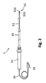
図2は、血管壁の状態の評価のために使用される機器5の例示的な実施形態を示す。機器は、ハンドグリップ51、管状の長尺シャフト54、管状の長尺シャフト54より遠位に届く伸長可能な、より可撓性のあるシャフト53、接続ケーブル56、及び機器を装置6に接続するコネクタ55を有する。代替として、機器5は、単に、可撓性シャフト53を有するガイドワイヤであってもよく、ケーブル56は、ガイドワイヤの延長でありえ、患者インタフェースモジュールに接続可能なコネクタ55を有する近位端部で終端する。ガイドワイヤ構成において、機器5は、管状のハンドグリップ51及び管状の細長体54を有する案内管シースのルーメンを通して患者の血管構造に挿入される。Volcano社によって製造されるComboWire XTガイドワイヤの構成と同様に、機器5の遠位端52には、圧力センサ521及びフローセンサ522の2つのセンサが組み込まれている。一般的な圧力センサは、圧力印加時のピエゾ抵抗の特性変化、機械的又は電気的信号に対するダイアフラムの撓みの流体変換、及び基板上に懸架されたメンブレンの容量読み出し値を使用する。一般に介入医療器具に組み込まれるフローセンサは、血管の血流速度を測定するために、超音波のドップラ効果又はレーザ放射を使用する。血流速度測定のための超音波は、圧電セラミック(PZT)又はプラスチック(PVDF)材料によって、あるいは、容量性又は圧電マイクロマシン超音波トランスデューサ(cMUT又はpMUT)によって生成されることができる。
FIG. 2 shows an exemplary embodiment of
図3において、遠位先端部52の代替の実施形態が、機器の部分断面図に概略的に示されている。側方を向くメンブレンを有するcMUT圧力センサ521が、遠位先端部52に組み込まれ、血液がメンブレン上に圧力を及ぼすことを可能にする。機器の遠位方向を向く圧電超音波トランスデューサ522が、軸方向のフロー速度測定のために組み込まれる。横断面526は、cMUT圧力センサの長手軸525によって規定される。センサは、機器を血管内腔に入れ及び血管の単一の横断面に配置することによって、機器5の同じ横断面526内において血流速度及び血圧を測定する。
In FIG. 3, an alternative embodiment of the
遠位先端部52の代替の実施形態が、図4に概略的に示される。ピエゾ抵抗圧力センサ521は、それが機器5の遠位端527を含む横断面526の血圧を測定するように組み込まれる。拍動性血流速度は、機器に組み込まれる光学ファイバ523を有する光学センサにより測定される。この実施形態において、装置は、光学ファイバ523を通じて機器の遠位部分52に送信されるレーザ放射を生成するためのソースを含む。光学透明のキャビティ528が、機器の遠位端527から光学ファイバの遠位端を隔てることができる。キャビティ528は、ガラス、透明なプラスチック、又は光学透明な流体を充填されるコンパートメントでありうる。図1に示される装置6は、移動する血液から反射される光学信号を検出する検出器を有し、プロセッサは、送信レーザ放射に対する受信レーザ放射の周波数シフトから、血流速度を導出する。代替として、光学透明のキャビティが、機器の遠位端527において可撓性のメンブレンを有する場合、光学ファイバ523は、圧力測定のために使用されることができる。機器の遠位端に及ぼされる圧力は、メンブレンの撓みを引き起こし、メンブレンからのレーザ反射の光路変化は、メンブレンの既知の曲がりスチフネスに関する、及ぼされた圧力の尺度である。光路変化は、インタフェロメトリによって測定されることができ、この場合、基準光路は、光学ファイバ823の遠位端からの反射によって規定され、変化する光路は、機器の遠位端527においてキャビティをふさぐメンブレンの(内部の又は外部の)表面の1つからの反射によって規定される。他の代替例として、機器5の遠位端527においてメンブレンによってシールされる単一の光学ファイバ523及びキャビティ528が、血圧測定及び血流速度測定のために同時に使用されることができ、この場合、半透明のメンブレンの撓みが、メンブレンに及ぼされる血圧の尺度であり、機器5より遠位の血液の動きから生じるレーザ放射の周波数シフトが、血流速度の尺度である。
An alternative embodiment of the
拍動性血圧は、血管の内腔において局所的に測定されなければならないが、拍動性血流は、RA、CTA、MRA及びUIから導出されることができる。一例として、RAから導出される拍動性血流は、Bonnefous et al, "Quantification of arterial flow using digital subtraction angiography", Medical Physics, Vol.39, No.10, p.6264-75, 2012に開示されている。技法は、非常に控え目なレート(例えば1.5ml/s)で、ヨウ素コ造影剤を血管に注入することを含む。結果として、造影剤は、心臓周期によって駆動されるフロー拍動性によって注入ポイントにおいて変調される。造影剤は、拡張フェーズの最中はより高密度であり、収縮フェーズの最中はより高密度でない。変調される造影剤パターンが血管を通って進む。X線画像において、造影剤パターンは、光学フローアルゴリズムを使用して、血管軌道に沿ってたどられることができる。(例えば3D−RAによって得られる)血管ツリーの3D再構成をX線画像と突き合わせすることによって、フォアショートニングが考慮されることができ、血管直径が計算されることができる。フローを算出するために、造影剤の低い周波数の流入及び流出は、高い周波数の拍動性成分から分離される。フロー測定は、機器5からの圧力測定と時間的に同期される必要があり、これは、圧力測定と、血管への造影剤の注入を同期することによって実現される。任意に、血圧を測定するのと同じシステム(例えば1つの統合された案内カテーテル/圧力ガイドワイヤアセンブリ)により造影剤を注入することが可能である。
Pulsating blood pressure must be measured locally in the lumen of blood vessels, while pulsatile blood flow can be derived from RA, CTA, MRA and UI. As an example, pulsatile blood flow derived from RA is disclosed in Bonnefous et al, "Quantification of arterial flow using digital subtraction angiography", Medical Physics, Vol.39, No.10, p.6264-75, 2012. Has been done. The technique involves injecting an iodine contrast medium into the blood vessels at a very modest rate (eg, 1.5 ml / s). As a result, the contrast agent is modulated at the injection point by the flow pulsation driven by the cardiac cycle. The contrast agent is denser during the expansion phase and less dense during the contraction phase. A modulated contrast agent pattern travels through the blood vessels. In an X-ray image, the contrast agent pattern can be traced along the vascular trajectory using an optical flow algorithm. By matching the 3D reconstruction of the vessel tree (eg obtained by 3D-RA) with an X-ray image, fore shortening can be considered and the vessel diameter can be calculated. To calculate the flow, the low frequency inflows and outflows of the contrast agent are separated from the high frequency pulsatile components. The flow measurement needs to be time synchronized with the pressure measurement from the
図5は、左分岐11及び右分岐12を有する分岐血管の血管造影投影10を示す。本発明の例示的な記述のために、右分岐12は、円によってマークされた領域13内にループ及び隆起を有する。図6に示されるように、領域13の拡大された3次元血管形態表現20が、血管造影投影に基づいて再構成され、右の血管分岐12は、動脈瘤14の形成に至った弱化した血管壁を有する領域を有する。一般に、動脈瘤は、円周頸部15を示し、それは弱化した血管壁のセグメントを表現する。3次元モデルが更に、処置計画のためにフローダイバーティングステント16をカスタマイズする可能性を与えることができる。
FIG. 5 shows an
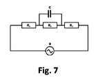
脈管系は、抵抗器及びキャパシタの等価な電気回路として簡略化された形で表現されることができ、それにより、血管は、抵抗器によって表現され、動脈瘤は、キャパシタによって表現される。単一の血管の抵抗は、その半径及びその長さによって算出される。血管ネットワークは、単一の抵抗器に畳まれることができる。動脈瘤の容量は、そのボリューム、その頸部15領域、及びその位置によって算出される。動脈瘤を有する血管ネットワークは、図7に示すようにモデル化されることができる。発振源Sは、心臓を表現し、電位の電気等価を有する周期的血圧且つ及び電流の電気等価を有する周期的な血流のソースである。抵抗器R1、R2及びR3は、それぞれ、動脈瘤より近位における全体血管ネットワークの抵抗、動脈瘤14を保持する血管セグメントの抵抗、及び動脈瘤より遠位における全体血管ネットワークの抵抗を表す。キャパシタCは、血流上の動脈瘤14の影響をモデル化する。血管ネットワークの複雑さは、等価電気回路への素子の付加によって一層増大されることができる。
The vascular system can be represented in a simplified form as an equivalent electrical circuit of resistors and capacitors, whereby blood vessels are represented by resistors and aneurysms are represented by capacitors. The resistance of a single blood vessel is calculated by its radius and its length. The vascular network can be folded into a single resistor. The volume of an aneurysm is calculated by its volume, its
概略的に図8aに示される健康な血管壁の場合、キャパシタCは、動脈瘤の不存在のため、電気ネットワークから除かれている。血圧及び血流は、機器5により、血管12内のセンサ521及び522の位置において測定される。代替として、血流は、血圧センサの位置についてRA、CTA、MRA又はUIから導出されることができ、この場合、機器5は、圧力センサ521のみを有し、血流測定は、圧力測定にと間的に同期される。健康な血管セグメントの場合、図8bに例示的に示されるように、血流及び血圧をそれぞれ表現する電流及び電位は、抵抗器R2の両端で同じ位相である。期間T 620を有する拍動性の動きは、周期的な心拍によって生成される。実線621は、瞬時血圧測定信号を表現し、点線622は、瞬時血流測定信号を表現する。
In the case of the healthy vessel wall, schematically shown in FIG. 8a, the capacitor C has been removed from the electrical network due to the absence of an aneurysm. Blood pressure and blood flow are measured by
図9aは、血管壁の弱化したセグメントにより形成される動脈瘤14の例を示す。センサ521、522を有する遠位先端部52の位置は、血流の方向に関して動脈瘤より遠位にある。好適には、測定信号は、動脈瘤14の頸部15から同じ距離のところに生じ、かかる信号は、図3、図4に示される機器5の実施形態のうちの1つによって、又は、一般的なプレッシャワイヤ(例えばVolcano社からのVerrata Pressure Guide)及び拍動性血流を導き出すために使用されるRA、CTA、MRA及びUIからのモダリティの1つによって、提供されることができる。
FIG. 9a shows an example of an
図9bに示されるように、動脈瘤の存在は、等価電気回路の抵抗器R2とR3の間で測定される電位と電流の間の位相差と同様に、測定された血圧621と測定された血流622との間に位相差t 630をもたらす。位相差の尺度は、血管壁の状態を表し、ゆえに動脈瘤のサイズを表す。位相差630の検出のために、拍動性血圧及び拍動性血流の絶対的な値を正確に測定することは重要ではなく、なぜなら、拍動性は、相対的な血圧測定信号及び血流測定信号から容易に導出可能であるからである。従って、測定の較正は必要ではなく、これは、技法の大きな利点である。
As shown in FIG. 9b, the presence of an aneurysm was measured with the measured
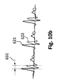
動脈瘤の一般的な処置は、血管へのフローダイバーティングステントの並置であり、それにより、弱化した血管セグメント及び弱化したセグメントより近位及び遠位の隣接部分が、カバーされ、更なる弱化から保護する。図10aは、動脈瘤14に流れ込む血液を制限するステント16の例を示す。ステントは、第一に、動脈瘤破裂の増大されるリスクをもたらす動脈瘤のより大きいサイズへの成長を防ぎ、第2に、それは、動脈瘤内にすでに存在する血液が、凝固し、すでに弱化した血管壁の更なる保護を形成することを可能にする。フローダイバーティングステント16を配置することは、等価電気回路おける動脈瘤のキャパシタンスCを低下させ、電位と電流の間の位相差が低減する結果をもたらす。図10bは、測定された血圧621及び血流622に対するフローダイバーティングステント並置の効果を示す。誤って配置されるステントは、動脈瘤14のキャパシタンスCに対するより少ない影響を有するので、フローダイバーティングステント並置の位相差変化(631と比較した630)は、ステント配置の有効性の尺度である。処置の期待される結果は、動脈瘤の成長を止め、凝結した血液が、動脈瘤の壁を完全にブロックし、保護することである。従って、患者のフォローアップ検査において、位相差631は、一層低下することが期待され、より長い持続時間の後、位相差を潜在的に示さない。
A common treatment for aneurysms is the juxtaposition of a flow diverting stent into the blood vessel, thereby covering the weakened vascular segment and adjacent parts proximal and distal to the weakened segment, from further weakening. Protect. FIG. 10a shows an example of a
動脈瘤の代替の、しかしより効果的でない処置は、動脈瘤ポケットの利用可能なボリュームを低下させることによって動脈瘤に流れ込む血液を制限する意図で、動脈瘤内に複数コイルを配置することである。処置が成功せず、動脈瘤のサイズが大きくなり続ける場合、フローダイバーティングステント並置が必要である。コイル配置は、問題に非常に局所的に対処するが、フローダイバーティングステントは、貧弱な状態を同様に呈することがある動脈瘤の近位及び遠位の血管壁セグメントを保護する。フローダイバーティングステント16並置に先立つコイル17の配置によって処置される動脈瘤14の例が、図11に示されており、図において、血管モデル内の動脈瘤が、コイル17を可視にするために部分的に切断されている。
An alternative, but less effective, treatment for an aneurysm is to place multiple coils within the aneurysm with the intention of limiting the blood flowing into the aneurysm by reducing the available volume of the aneurysm pocket. .. If the procedure is unsuccessful and the aneurysm continues to grow in size, a flow diverting stent juxtaposition is required. Although coil placement addresses the problem very locally, flow diverting stents protect the proximal and distal vessel wall segments of the aneurysm, which can also exhibit poor conditions. An example of an
プロセッサが、測定された拍動性血圧信号621と拍動性血流信号622との間の位相差630、631を決定すると、プロセッサは、装置6に組み込まれたディスプレイ61上に、又は、医師に利用可能な別個のスクリーン上に、図8b、9b、10bに示されるグラフィック表現を描画することができる。代替的に又は追加的に、ディスプレイは、位相差tに対応している値、又は連続的な心拍の間の期間Tに対する位相差のパーセンテージを提示することができる。プロセッサは、イメージングユニット3から受けられる情報から、血管構造の形態学的な表現20を、ディスプレイ61に描画することができる。イメージングユニット3は、血管構造の形態に対する機器5の位置に関する情報を更に提供することができる。RA又はCTAにおける機器5の遠位先端部52の追跡は、遠位先端部に組み込まれる放射線マーカを使用することによって達成されることができる。代替として、UIにおいて、機器5の位置の追跡は、能動的な超音波センサを遠位先端部に組み込むことによって実現されることができる。超音波センサは、患者2の身体の中の血管内から超音波を送信し、超音波信号の一部が、体内又は体外の超音波イメージングユニット3によって受けられ、超音波イメージングユニット3は更に、その視野内のターゲット血管構造の形態学的情報を更に提供し、これは、血管形態内の遠位先端部52の連続する位置特定を可能にする。センサ521、522及び/又は機器5の位置の、形態学的表現20上への視覚化は、図8a、図9a、図10aのように表示されることができる。血管の形態に対し機器の位置を追跡することによって、及び拍動性血圧と拍動性血流の間の位相差を知ることによって、血管壁の弱化したセグメントが識別され、ディスプレイ上でタグ付けされることができる。
When the processor determines the
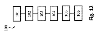
図12は、患者の血管壁の状態を特徴付ける方法100を概略的に示す。ステップ101において、装置6は、血管内の拍動性血液運動の瞬時圧力測定信号621及びフロー測定信号622を受け取り、ステップ102において、装置6のプロセッサは、血管壁の状態を示す、拍動性血圧測定信号621と拍動性血流測定信号622の間の位相差630、631を決定する。好適には、測定情報を提供するセンサは、、機器の同じ横断面526における血圧測定621及び血流測定622を提供するために、図3及び図4に示すように機器5に組み込まれる。圧力測定及び血流測定は、代替として、2つセンサが血管の同じ横断面における測定を提供しない図2に示すような機器によって実施されることができる。結果として、血圧の測定又は血流の測定は、遠位先端部52に組み込まれた2つのセンサ521、522の間の知られている距離に起因する位相オフセットを補償されなければならない。代替として、各々が単一のセンサを有する2つの異なる機器が、血管に挿入されることができ、よって、圧力測定は、圧力ワイヤ(例えばVolcano社からのVerrata)によって行われることができ、血流は、ドップラーガイドワイヤ(例えばVolcano社からFloWire)によって測定されることができる。方法の一実施形態において、圧力は、圧力ワイヤによって測定され、血流は、血流イメージングモダリティRA、CTA、MRA、UIのうちの1つに関連するイメージングユニット3によって測定される。方法は更に、血管壁の状態を示す、拍動性血圧測定信号621と拍動性血流測定信号622の間の位相差630の表現を、ディスプレイ61上に描画するステップ103を有する。ステップ104において、装置6のプロセッサは、イメージングユニット3によって提供される形態学的情報から、血管の形態学的表現20をディスプレイ61上に描画するように構成される。ステップ105において、イメージングユニット3は、血管の形態に対して機器5の位置を追跡し、ステップ106において、機器5の位置は、血管の形態学的表現20上に表示される。
FIG. 12 schematically shows a
方法100の一実施形態において、瞬時圧力測定信号621及びフロー測定信号622は、血管壁の動脈瘤14を有する血管から発せされ、血流の方向に関して動脈瘤14の遠位において測定信号が発せられる。動脈瘤より近位の測定値は、更に別の動脈瘤が個々の測定ロケーションの近位に存在しない限り、拍動性圧力と血流の間の位相差を潜在的に示さず、これは、健康な血管壁を表す。方法は、圧力センサ及びフローセンサの両方を有する機器5のプルバック中、又は圧力センサのみを有する機器をプルバックすること及びプルバックされた機器の追跡された軌道に沿ってイメージングユニット3により血流を測定することによって、血管に沿った血管壁の弱さの検出を可能にする。プルバックレートは、機器のプルバック軌道に沿った離散的な測定ロケーションにおいて、位相差630の潜在的な存在を算出するのに十分な時間を与える。
In one embodiment of
一実施形態において、方法100は、フローダイバーティングステント16並置の有効性を評価するために使用される。フローダイバーティングステントは、動脈瘤壁を引っ張る周期的な圧力を低減するために、血液が動脈瘤に流れ込むことを少なくとも部分的に妨げる。動脈瘤への血流の低減は、更に、動脈瘤内血栓形成を促進する。フローダイバーティングステントの正確な並置は、ステント並置の前の位相差630に対する、拍動性圧力測定信号621と拍動性血流信号622との間の並置後の位相差631の大幅な低減によって検出可能である。
In one embodiment,
方法100は、動脈瘤14へのコイル17配置の初期処置の後の、フローダイバーティングステント16並置の有効性を評価するために使用されることができる。コイルによる処置の潜在的な弱点は、より長い期間では、動脈瘤の初期頸部15の近傍の血管壁が、一層弱化しうることである。正しく並置されるステントは、動脈瘤頸部15を保護すると共に、動脈瘤14の頸部15の近位及び遠位の近傍の血管壁を保護する。
方法100の一実施形態において、瞬時圧力測定信号621及びフロー測定信号622は、好適には、動脈瘤14の頸部15から同じ距離のところで発せられ、それにより、動脈瘤頸部15に対する圧力測定及び血流測定のロケーションの間の異なる距離によって引き起こされる瞬時オフセットがないという利点を有する。
In one embodiment of
医療装置が、本発明の例示的な記述において使用されているが、本発明の範囲を制限するものとして解釈されるべきでない。 The medical device is used in the exemplary description of the invention, but should not be construed as limiting the scope of the invention.
開示される実施形態に対する他の変更例は、図面、開示及び添付の請求項の検討により、請求項に記載の本発明を実施する際に当業者によって理解され達成されることができる。 Other modifications to the disclosed embodiments can be understood and achieved by those skilled in the art in carrying out the invention described in the claims by reviewing the drawings, disclosure and the accompanying claims.
単一のユニット又装置は、請求項に列挙されるいくつかのアイテムの機能を果たすことができる。特定の手段が相互に異なる従属請求項に列挙されているという単なる事実は、これらの手段の組み合わせが有利に使用されることができないことを示さない。 A single unit or device can perform the function of several items listed in the claims. The mere fact that certain means are listed in different dependent claims does not indicate that a combination of these means cannot be used in an advantageous manner.
請求項において、「含む、有する(comprising)」という語は、他の構成要素を除外せず、「a」又は「an」の不定冠詞は、複数性を除外しない。 In the claims, the word "comprising" does not exclude other components, and the indefinite article "a" or "an" does not exclude pluralities.
請求項における任意の参照符号は、請求項の範囲を制限するものとして解釈されるべきでない。 Any reference code in the claims should not be construed as limiting the scope of the claims.
Claims (15)
血管内に挿入される場合に前記血管内の拍動性血液運動の瞬時圧力測定信号を提供する機器と、
前記血管の形態学的情報を提供し、前記血管の形態に対して前記機器の位置を追跡するイメージングユニットと、
を有するシステムにおいて、
前記装置は、
前記機器からの前記瞬時圧力測定信号及び前記血管内の前記拍動性血液運動の瞬時フロー測定信号を受け取り、
前記血管壁の状態を示す、前記瞬時圧力測定信号と前記瞬時フロー測定信号との間の位相差を決定する、
ように構成されるプロセッサを有する、
システム。 A device that characterizes the condition of the blood vessel wall of an organism,
A device that provides an instantaneous pressure measurement signal for pulsatile blood movement in a blood vessel when inserted into a blood vessel.
An imaging unit that provides morphological information on the blood vessel and tracks the position of the device relative to the morphology of the blood vessel.
In a system with
The device
Upon receiving the instantaneous pressure measurement signal from the device and the instantaneous flow measurement signal of the pulsatile blood movement in the blood vessel,
To determine the phase difference between the instantaneous pressure measurement signal and the instantaneous flow measurement signal, which indicates the state of the blood vessel wall .
Has a processor configured to
system.
前記プロセッサは、前記血管壁の状態を示す、前記瞬時圧力測定信号と前記瞬時フロー測定信号との間の位相差の表現を、前記ディスプレイ上に描画するように構成される、請求項1に記載のシステム。 Has more displays
The processor according to claim 1, wherein the processor is configured to draw on the display an expression of the phase difference between the instantaneous pressure measurement signal and the instantaneous flow measurement signal, which indicates the state of the blood vessel wall. System.
前記プロセッサが、前記機器から前記瞬時圧力測定信号を受け取るステップと、
前記プロセッサが、前記血管内の拍動性血液運動の瞬時フロー測定信号を受け取るステップと、
前記イメージングユニットが、前記血管の形態学的情報を提供するステップと、
前記イメージングユニットが、前記血管の形態に対して前記機器の位置を追跡するステップと、
前記プロセッサが、前記血管壁の状態を示す、前記瞬時圧力測定信号と前記瞬時フロー測定信号との間の位相差を決定するステップと、
を有する方法。 A method of operating a system that characterizes the condition of an organism's blood vessel wall, the system providing a device having a processor, an instantaneous pressure measurement signal of pulsatile blood movement in the blood vessel when inserted into the blood vessel. The method comprises an instrument and an imaging unit.
Wherein the processor comprises the steps of receiving the instantaneous pressure measuring signal from the apparatus,
When the processor receives an instantaneous flow measurement signal of pulsatile blood movement in the blood vessel,
A step in which the imaging unit provides morphological information on the blood vessel,
A step in which the imaging unit tracks the position of the device relative to the morphology of the blood vessel.
A step in which the processor determines the phase difference between the instantaneous pressure measurement signal and the instantaneous flow measurement signal, which indicates the state of the blood vessel wall.
Method to have.
を有する、請求項11に記載の方法。 A step in which the processor displays the position of the device on the morphological representation of the blood vessel.
11. The method of claim 11.
前記血管壁の状態を示す、前記瞬時圧力測定信号と前記瞬時フロー測定信号との間の位相差を決定するステップが、前記機器のプルバック軌道に沿った離散的な測定ロケーションにおいて行われる、
請求項9に記載の方法。 The step of receiving the instantaneous pressure measurement signal of the pulsatile blood movement in the blood vessel from the device is performed along the trajectory of the device during the pullback movement in the blood vessel.
The step of determining the phase difference between the instantaneous pressure measurement signal and the instantaneous flow measurement signal, which indicates the state of the vessel wall, is performed at discrete measurement locations along the pullback trajectory of the instrument.
The method according to claim 9.
Applications Claiming Priority (3)
| Application Number | Priority Date | Filing Date | Title |
|---|---|---|---|
| EP15189794.9 | 2015-10-14 | ||
| EP15189794 | 2015-10-14 | ||
| PCT/EP2016/074118 WO2017063963A1 (en) | 2015-10-14 | 2016-10-10 | Apparatus for characterizing a vessel wall |
Publications (3)
| Publication Number | Publication Date |
|---|---|
| JP2018534039A JP2018534039A (en) | 2018-11-22 |
| JP2018534039A5 JP2018534039A5 (en) | 2019-10-03 |
| JP6794440B2 true JP6794440B2 (en) | 2020-12-02 |
Family
ID=54325443
Family Applications (1)
| Application Number | Title | Priority Date | Filing Date |
|---|---|---|---|
| JP2018518474A Active JP6794440B2 (en) | 2015-10-14 | 2016-10-10 | A device that characterizes the walls of blood vessels |
Country Status (5)
| Country | Link |
|---|---|
| US (2) | US11202575B2 (en) |
| EP (2) | EP4011282A1 (en) |
| JP (1) | JP6794440B2 (en) |
| CN (1) | CN108135490B (en) |
| WO (1) | WO2017063963A1 (en) |
Families Citing this family (2)
| Publication number | Priority date | Publication date | Assignee | Title |
|---|---|---|---|---|
| CN108135490B (en) * | 2015-10-14 | 2022-01-11 | 皇家飞利浦有限公司 | Device for characterizing a vessel wall |
| US20210113101A1 (en) * | 2018-04-19 | 2021-04-22 | The General Hospital Corporation | Method and apparatus for measuring intravascular blood flow using a backscattering contrast |
Family Cites Families (28)
| Publication number | Priority date | Publication date | Assignee | Title |
|---|---|---|---|---|
| AU1781699A (en) * | 1998-01-12 | 1999-07-26 | Florence Medical Ltd. | A system and method for characterizing lesions and blood vessel walls using multi-point pressure measurements |
| US6309359B1 (en) * | 1998-06-01 | 2001-10-30 | Michael D. Whitt | Method and apparatus for noninvasive determination of peripheral arterial lumenal area |
| US6471656B1 (en) * | 1999-06-25 | 2002-10-29 | Florence Medical Ltd | Method and system for pressure based measurements of CFR and additional clinical hemodynamic parameters |
| US6338719B1 (en) | 2000-06-12 | 2002-01-15 | Rutgers, The State University Of New Jersey | Method and system for detecting vascular conditions using an occlusive arm cuff plethysmograph |
| EP1460935A2 (en) * | 2001-08-17 | 2004-09-29 | Ted W. Russell | Methods, apparatus and sensor for hemodynamic monitoring |
| GB0208945D0 (en) | 2002-04-19 | 2002-05-29 | Univ Belfast | Vascular impedance measurement apparatus |
| US7930014B2 (en) * | 2005-01-11 | 2011-04-19 | Volcano Corporation | Vascular image co-registration |
| US8340744B2 (en) * | 2005-12-15 | 2012-12-25 | Koninklijke Philips Electronics N.V. | System, apparatus, and method for reproducible and comparable flow acquisitions |
| US20100076317A1 (en) * | 2006-11-30 | 2010-03-25 | Koninklijke Philips Electronics N.V. | Catheter with ultrasound transducer and variable focus lens used in aneurysm assessment |
| JP5109027B2 (en) * | 2007-03-30 | 2012-12-26 | 国立大学法人京都大学 | Blood vessel state evaluation apparatus, blood vessel state evaluation method, and blood vessel state evaluation program |
| JP2010525913A (en) | 2007-05-09 | 2010-07-29 | コーニンクレッカ フィリップス エレクトロニクス エヌ ヴィ | Sensor probe for measuring physical properties inside the body lumen |
| CA2691211C (en) * | 2007-06-26 | 2017-03-21 | Sorin Grunwald | Apparatus and method for endovascular device guiding and positioning using physiological parameters |
| CN101278828A (en) * | 2008-05-20 | 2008-10-08 | 上海大学 | Method for measuring micro-area work of ventricular wall |
| WO2012173697A1 (en) * | 2011-06-13 | 2012-12-20 | Angiometrix Corporation | Multifunctional guidewire assemblies and system for analyzing anatomical and functional parameters |
| CN102939051A (en) | 2010-06-13 | 2013-02-20 | 安吉奥梅特里克斯公司 | Methods and systems for determining vascular bodily lumen information and guiding medical devices |
| US20140003687A1 (en) * | 2011-01-14 | 2014-01-02 | Baylor College Of Medicine | Method and system for evaluating hemodynamics of a blood vessel |
| US20140243688A1 (en) * | 2011-10-28 | 2014-08-28 | Three Rivers Cardiovascular Systems Inc. | Fluid temperature and flow sensor apparatus and system for cardiovascular and other medical applications |
| CN108294735B (en) * | 2012-03-13 | 2021-09-07 | 西门子公司 | Method and system for non-invasive functional assessment of coronary artery stenosis |
| CN104427930A (en) * | 2012-04-05 | 2015-03-18 | 巴德阿克塞斯系统股份有限公司 | Devices and systems for navigation and positioning central venous catheter within patient |
| US9549679B2 (en) * | 2012-05-14 | 2017-01-24 | Acist Medical Systems, Inc. | Multiple transducer delivery device and method |
| US20140005512A1 (en) | 2012-06-27 | 2014-01-02 | Kim Manwaring | Electrically Resonant Electrode Configuration for Monitoring of a Tissue |
| US20140066765A1 (en) * | 2012-08-31 | 2014-03-06 | General Electric Company | Methods and systems for intravascular imaging and flow measurement |
| US10820872B2 (en) * | 2012-12-19 | 2020-11-03 | Koninklijke Philips N.V. | X-ray controlled contrast agent injection |
| EP2967391A4 (en) * | 2013-03-12 | 2016-11-02 | Donna Collins | Systems and methods for diagnosing coronary microvascular disease |
| EP3076864B1 (en) * | 2013-12-06 | 2021-03-10 | Philips Image Guided Therapy Corporation | Device for assessing intravascular pressure |
| EP3091905B1 (en) | 2014-01-10 | 2022-12-21 | Philips Image Guided Therapy Corporation | Detecting endoleaks associated with aneurysm repair |
| ES2883138T3 (en) * | 2014-04-04 | 2021-12-07 | St Jude Medical Systems Ab | Intravascular Pressure and Flow Data Diagnostic System |
| CN108135490B (en) * | 2015-10-14 | 2022-01-11 | 皇家飞利浦有限公司 | Device for characterizing a vessel wall |
-
2016
- 2016-10-10 CN CN201680060116.1A patent/CN108135490B/en active Active
- 2016-10-10 US US15/767,778 patent/US11202575B2/en active Active
- 2016-10-10 JP JP2018518474A patent/JP6794440B2/en active Active
- 2016-10-10 WO PCT/EP2016/074118 patent/WO2017063963A1/en active Application Filing
- 2016-10-10 EP EP21217313.2A patent/EP4011282A1/en active Pending
- 2016-10-10 EP EP16778813.2A patent/EP3361932B1/en active Active
-
2021
- 2021-12-11 US US17/548,505 patent/US11864869B2/en active Active
Also Published As
| Publication number | Publication date |
|---|---|
| CN108135490A (en) | 2018-06-08 |
| EP3361932B1 (en) | 2022-01-19 |
| US11202575B2 (en) | 2021-12-21 |
| CN108135490B (en) | 2022-01-11 |
| EP4011282A1 (en) | 2022-06-15 |
| EP3361932A1 (en) | 2018-08-22 |
| US20220095935A1 (en) | 2022-03-31 |
| US11864869B2 (en) | 2024-01-09 |
| WO2017063963A1 (en) | 2017-04-20 |
| JP2018534039A (en) | 2018-11-22 |
| US20180296100A1 (en) | 2018-10-18 |
Similar Documents
| Publication | Publication Date | Title |
|---|---|---|
| JP6521476B2 (en) | Device for vascular characterization | |
| JP7071442B2 (en) | Equipment and methods for navigation, evaluation and / or diagnosis of blood vessels | |
| JP6906113B2 (en) | Devices, systems and methods for visualizing cyclically moving biological structures | |
| JP7117999B2 (en) | Endovascular processing system for assessment, planning and treatment of coronary interventions based on desired outcome | |
| CN107920745A (en) | Intravascular data visualization method | |
| US11864869B2 (en) | Apparatus for characterizing a vessel wall | |
| JP2017503585A (en) | Detection of endoleak associated with aneurysm repair | |
| JP2014500043A (en) | Bifurcation detection using traceable imaging devices and imaging tools | |
| CN106535746A (en) | Devices, systems, and methods for treatment of vessels | |
| US20220167938A1 (en) | Apparatus for vessel characterization | |
| CN114667099A (en) | System and method for combined imaging | |
| US20230338010A1 (en) | Automated control of intraluminal data acquisition and associated devices, systems, and methds | |
| US11918325B2 (en) | Pulse wave velocity measurement system | |
| EP3714780A1 (en) | Pulse wave velocity measurement system | |
| WO2023235854A1 (en) | Systems and methods for endoluminal tracking with therapeutic delivery sensing | |
| JP2020532351A (en) | Equipment and methods for navigation, evaluation and / or diagnosis of blood vessels | |
| EP3349659A1 (en) | Apparatus for vessel characterization |
Legal Events
| Date | Code | Title | Description |
|---|---|---|---|
| A521 | Request for written amendment filed |
Free format text: JAPANESE INTERMEDIATE CODE: A523 Effective date: 20190814 |
|
| A621 | Written request for application examination |
Free format text: JAPANESE INTERMEDIATE CODE: A621 Effective date: 20190814 |
|
| A977 | Report on retrieval |
Free format text: JAPANESE INTERMEDIATE CODE: A971007 Effective date: 20200422 |
|
| A131 | Notification of reasons for refusal |
Free format text: JAPANESE INTERMEDIATE CODE: A131 Effective date: 20200623 |
|
| A521 | Request for written amendment filed |
Free format text: JAPANESE INTERMEDIATE CODE: A523 Effective date: 20200916 |
|
| TRDD | Decision of grant or rejection written | ||
| A01 | Written decision to grant a patent or to grant a registration (utility model) |
Free format text: JAPANESE INTERMEDIATE CODE: A01 Effective date: 20201105 |
|
| A61 | First payment of annual fees (during grant procedure) |
Free format text: JAPANESE INTERMEDIATE CODE: A61 Effective date: 20201111 |
|
| R150 | Certificate of patent or registration of utility model |
Ref document number: 6794440 Country of ref document: JP Free format text: JAPANESE INTERMEDIATE CODE: R150 |
|
| R250 | Receipt of annual fees |
Free format text: JAPANESE INTERMEDIATE CODE: R250 |