JP6793623B2 - Observation equipment, observation equipment, observation unit and medical care unit - Google Patents
Observation equipment, observation equipment, observation unit and medical care unit Download PDFInfo
- Publication number
- JP6793623B2 JP6793623B2 JP2017215272A JP2017215272A JP6793623B2 JP 6793623 B2 JP6793623 B2 JP 6793623B2 JP 2017215272 A JP2017215272 A JP 2017215272A JP 2017215272 A JP2017215272 A JP 2017215272A JP 6793623 B2 JP6793623 B2 JP 6793623B2
- Authority
- JP
- Japan
- Prior art keywords
- observation
- unit
- eyepiece
- magnifying glass
- head
- Prior art date
- Legal status (The legal status is an assumption and is not a legal conclusion. Google has not performed a legal analysis and makes no representation as to the accuracy of the status listed.)
- Active
Links
Images


Landscapes
- Microscoopes, Condenser (AREA)
- Dental Tools And Instruments Or Auxiliary Dental Instruments (AREA)
- Accommodation For Nursing Or Treatment Tables (AREA)
- Image Input (AREA)
Description
本発明は、例えば、口腔領域における所望の観察部位を観察する観察器具、観察装置、観察ユニット及び診療ユニットに関する。 The present invention relates to, for example, an observation instrument, an observation device, an observation unit, and a medical treatment unit for observing a desired observation site in the oral region.
従来より、例えば、歯科医療分野等において、歯牙に対する根管治療の際には、顕微鏡で歯牙を観察して治療することで精密な根管治療を行うようになってきている(特許文献1参照)。
例えば、特許文献1に記載の顕微鏡付診療台もそのひとつであるが、特許文献1に記載の顕微鏡付診療台は、医療用診療台の近傍に配置された支持アームに顕微鏡が支持されており、術者(観察者)は顕微鏡で観察部位を観察しながら精密な診療を行うことができる。
Conventionally, for example, in the field of dentistry, when root canal treatment for teeth, precise root canal treatment has been performed by observing and treating the teeth with a microscope (see Patent Document 1). ).
For example, the medical table with a microscope described in
しかしながら、術者は、顕微鏡をのぞきながら診療するため、むやみに頭部を移動させることができなかった。そこで、特許文献2に記載されるように、観察部位を撮像する撮像部を支持アームに備えるとともに、撮像部で撮像された観察部位の動画をHMD(Head Mount Display)で見ながら診療する顕微鏡検査システムが提案されている。これにより、術者は、頭部を自由に移動させても観察部位の画像を見ながら治療できるとされている。
しかし、HMDは大きく、また軽くないため、HMDを頭部に装着しながら診療し続けることは、術者にとって大きな負担であり、術者にとって満足できるものではなかった。
However, the surgeon was unable to move his head unnecessarily because he was treated while looking through the microscope. Therefore, as described in Patent Document 2, the support arm is provided with an imaging unit for imaging the observation site, and a microscopic examination is performed while viewing the moving image of the observation site imaged by the imaging unit on the HMD (Head Mount System). The system has been proposed. As a result, the surgeon can treat while looking at the image of the observation site even if the head is freely moved.
However, since the HMD is large and not light, it is a heavy burden for the operator to continue the medical treatment while wearing the HMD on the head, and the operator is not satisfied.
そこで本発明は、支持部に支持された状態と、頭部に装着した状態とを選択して、観察部位を観察できる観察器具、観察装置、観察ユニット及び診療ユニットを提供することを目的とする。 Therefore, an object of the present invention is to provide an observation instrument, an observation device, an observation unit, and a medical treatment unit capable of observing an observation site by selecting a state of being supported by a support portion and a state of being attached to a head. ..
この発明は、支持部に支持され、観察部位を観察する観察器具と、観察者の頭部に装着する頭部装着部とが備えられ、前記観察器具は、前記観察部位側の対物部、観察者側の接眼部、並びに前記対物部を介して採光した前記観察部位の光学像を前記接眼部へと伝送する光学像伝送部で構成されるとともに、前記対物部と前記接眼部と前記光学像伝送部のうち少なくとも前記接眼部を含む一部または全部を分離部として前記支持部から着脱する着脱部と、前記頭部装着部に、前記分離部を着脱可能に連結する連結部とが設けられ、前記着脱部に、前記連結部の連結によって前記着脱部の装着状態を解除する着脱解除部が設けられるとともに、前記連結部に、前記着脱部の装着によって前記連結部の連結状態を解除する連結解除部が設けられた観察装置であることを特徴とする。 The present invention includes an observation instrument that is supported by a support portion and observes an observation site, and a head-mounted portion that is attached to the observer's head. The observation instrument includes an objective portion and an observation device on the observation site side. It is composed of an eyepiece on the person's side and an optical image transmission unit that transmits an optical image of the observation site collected through the objective unit to the eyepiece, and also includes the objective unit and the eyepiece. A detachable portion that detaches from the support portion with at least a part or all of the optical image transmission portion including the eyepiece portion as a separating portion, and a connecting portion that detachably connects the separating portion to the head mounting portion. Is provided , and the detachable portion is provided with a detachable release portion that releases the attached state of the detachable portion by connecting the connecting portion, and the connecting portion is provided with the connected state of the connecting portion by attaching the detachable portion. The observation device is provided with a disconnection part for releasing the connection .
またこの発明は、支持部に支持され、観察部位を観察する観察器具であって、前記観察部位側の対物部、観察者側の接眼部、前記対物部を介して採光した前記観察部位の光学像を前記接眼部へと伝送する光学像伝送部、前記対物部と前記接眼部と前記光学像伝送部のうち少なくとも前記接眼部を含む一部または全部を分離部として前記支持部から着脱する着脱部、及び観察者の頭部に装着する頭部装着部に対して前記分離部を着脱可能に連結する連結部が備えられ、前記着脱部に、前記連結部の連結によって前記着脱部の装着状態を解除する着脱解除部が設けられるとともに、前記連結部に、前記着脱部の装着によって前記連結部の連結状態を解除する連結解除部が設けられたことを特徴とする。 Further, the present invention is an observation instrument that is supported by a support portion and observes an observation site, and is an objective portion on the observation site side, an eyepiece portion on the observer side, and the observation portion that is illuminated via the objective portion. The support unit with at least a part or all of the optical image transmission unit that transmits the optical image to the eyepiece, the objective unit, the eyepiece, and the optical image transmission unit including the eyepiece as a separation unit. detaching portion to be detachable from, and the connecting portion is provided for detachably connecting the separation unit with respect to the head-mounted unit to be mounted on the observer's head, the detachable unit, the detachable by the connecting of the connecting portion It is characterized in that a attachment / detachment release portion for releasing the attached state of the portion is provided, and the connection release portion for releasing the connection state of the connection portion by attaching the attachment / detachment portion is provided in the connecting portion .
上記支持部は、天井、壁、床、スタンド、ワゴン又はラック、あるいは医療用診療台、スピットン台、医療用ロボット又はその他の医療機器等から延びる支持アーム等としてもよい。 The support may be a ceiling, wall, floor, stand, wagon or rack, or a support arm extending from a medical clinic, spitton, medical robot, or other medical device.
上記観察部位は、歯牙や歯牙内部、あるいは歯肉など口腔内の部位や、人間や動物の体の一部であってもよい。 The observation site may be a part of the oral cavity such as a tooth or the inside of a tooth, a gingiva, or a part of a human or animal body.
上記対物部は、観察部位側に配置されたレンズや、イメージセンサなどで構成する撮像部であってもよい。
前記接眼部は、観察者が覗き込むレンズや、内部に配置された液晶や有機ELディスプレイ等で構成する表示部を覗き込む構成であってもよい。
The objective unit may be an imaging unit composed of a lens arranged on the observation site side, an image sensor, or the like.
The eyepiece may be configured to look into a lens that the observer looks into, or a display part that is composed of a liquid crystal or an organic EL display arranged inside.
上記頭部装着部は、ヘッドギアタイプ、ヘルメットタイプ、サンバイザータイプ、ヘッドバンドタイプ、メガネタイプ、観察者が視力矯正等のために普段使用しているような一般のメガネのフレームに対してクリップで装着するタイプなど、頭部に分離部を装着できる様々なタイプとすることができる。
上述の分離部は、観察器具から分離した前記接眼部のみ、接眼部と前記光学像伝送部を構成する光学部品や電子部品の一部または全部、あるいは接眼部と対物部で構成する観察器具全体であってもよい。
The head-mounted part is a clip for a headgear type, a helmet type, a sun visor type, a headband type, a glasses type, and a frame of general glasses that an observer usually uses for vision correction, etc. It can be of various types such as a type that can be attached to the head.
The above-mentioned separation unit is composed of only the eyepiece separated from the observation instrument, a part or all of the optical components and electronic components constituting the eyepiece and the optical image transmission unit, or the eyepiece and the objective unit. It may be the entire observation instrument.
この発明により、観察部位を、支持部に支持された状態の観察器具で観察したり、頭部に装着した状態の観察器具で観察したりすることができる。
詳述すると、観察部位を観察する観察器具と、観察者の頭部に装着する頭部装着部とが備えられ、前記観察器具は、前記観察部位側の対物部、観察者側の接眼部、並びに前記対物部を介して採光した前記観察部位の光学像を前記接眼部へと伝送する光学像伝送部で構成されるとともに、前記対物部と前記接眼部と前記光学像伝送部のうち少なくとも前記接眼部を含む一部または全部を分離部として前記支持部から着脱する着脱部とが備えられているため、前記観察装置を支持する支持部から分離部を取り外すことができる。
According to the present invention, the observation site can be observed with an observation instrument in a state of being supported by the support portion, or can be observed with an observation instrument in a state of being worn on the head.
More specifically, an observation instrument for observing the observation site and a head-mounted portion to be attached to the observer's head are provided, and the observation instrument includes an objective portion on the observation site side and an eyepiece portion on the observer side. , And an optical image transmission unit that transmits the optical image of the observation site collected through the objective unit to the eyepiece, and of the objective unit, the eyepiece, and the optical image transmission unit. Since at least a part or all of the eyepiece including the eyepiece is provided as a separating part and a detachable part is provided for attaching and detaching from the supporting part, the separating part can be removed from the supporting part supporting the observation device.
また、観察者の頭部に装着する頭部装着部に対して、前記分離部を着脱可能に連結する連結部を備えているため、着脱部によって、前記支持部から取り外された分離部を観察者の頭部に装着する頭部装着部に連結することができる。 Further, since the head mounting portion to be mounted on the observer's head is provided with a connecting portion for detachably connecting the separating portion, the detaching portion observes the separated portion removed from the support portion. It can be connected to a head-mounted portion to be worn on a person's head.
したがって、観察者は、観察部位を、支持部に支持された状態の前記観察器具で負担なく観察したり、頭部に装着した状態の前記観察器具で、頭部の移動が規制されることなく観察したりすることができ、利便性や操作性を向上することができる。 Therefore, the observer can observe the observation site without burden with the observation device supported by the support portion, or the observation device worn on the head does not restrict the movement of the head. It can be observed and convenience and operability can be improved.
また、前記着脱部に、前記連結部の連結によって前記着脱部の装着状態を解除する着脱解除部が設けられるとともに、前記連結部に、前記着脱部の装着によって前記連結部の連結状態を解除する連結解除部が設けられているため、前記観察器具を、前記支持部と前記頭部装着部とに対して安全に付け替えることができる。 Further, the detachable portion is provided with a detachable release portion for releasing the attached state of the detachable portion by connecting the connecting portion, and the connecting portion is provided with the detachable portion for releasing the connected state by attaching the detachable portion. Since the connection release portion is provided , the observation instrument can be safely replaced with respect to the support portion and the head mounting portion.
詳述すると、前記連結部の連結によって前記着脱解除部が前記着脱部の装着状態を解除し、前記着脱部の装着によって前記連結解除部が前記連結部の連結状態を解除するため、つまり、前記着脱部と前記連結部のいずれかが装着又は連結しているため、前記観察器具を、前記支持部と前記頭部装着部とに対して安全に付け替えることができる。 More specifically, the attachment / detachment release portion releases the attachment state of the attachment / detachment portion by connecting the connecting portions, and the connection release portion releases the connection state of the connection portion by attaching the attachment / detachment portion, that is, the said. Since either the detachable portion and the connecting portion are attached or connected, the observation instrument can be safely replaced with respect to the support portion and the head mounting portion.
またこの発明は、支持部に支持され、観察部位を観察する観察器具と、観察者の頭部に装着する頭部装着部とが備えられ、前記観察器具は、前記観察部位側の対物部、観察者側の接眼部、並びに前記対物部を介して採光した前記観察部位の光学像を前記接眼部へと伝送する光学像伝送部で構成されるとともに、前記頭部装着部は前記観察器具に備えられ、前記対物部と前記接眼部と前記光学像伝送部のうち少なくとも前記接眼部を含む一部または全部を分離部として前記支持部から着脱する着脱部と、前記観察器具に対して、前記頭部に未装着の前記頭部装着部を回避させる回避部とが設けられた観察装置であることを特徴とする。 The present invention also includes an observation instrument supported by a support portion for observing the observation site and a head-mounted portion to be attached to the observer's head. The observation instrument is an objective portion on the observation site side. It is composed of an eyepiece on the observer side and an optical image transmission part that transmits an optical image of the observation part collected through the objective part to the eyepiece part, and the head-mounted part is the observation part. An attachment / detachment portion provided on the instrument, the objective portion, the eyepiece portion, and the optical image transmission portion, including at least a part or all of the eyepiece transmission portion, which is attached / detached from the support portion as a separation portion, and the observation instrument. On the other hand, the observation device is provided with an avoidance portion for avoiding the head-mounted portion that is not attached to the head.
さらにまたこの発明は、支持部に支持され、観察部位を観察する観察器具であって、前記観察部位側の対物部、観察者側の接眼部、前記対物部を介して採光した前記観察部位の光学像を前記接眼部へと伝送する光学像伝送部、前記対物部と前記接眼部と前記光学像伝送部のうち少なくとも前記接眼部を含む一部または全部を分離部として前記支持部から着脱する着脱部、及び前記頭部に装着される頭部装着部を観察器具本体に対して装着するとともに、回避させる回避部が設けられたことを特徴とする。 Furthermore, the present invention is an observation instrument that is supported by a support portion and observes an observation site, and the observation portion that is illuminated via the objective portion on the observation site side, the eyepiece portion on the observer side, and the objective portion. The optical image transmission unit that transmits the optical image to the eyepiece, the objective unit, the eyepiece, and the optical image transmission unit, at least a part or all of the optical image transmission unit including the eyepiece, is supported as a separation unit. It is characterized in that a detachable portion to be attached / detached from the portion and a head-mounted portion to be attached to the head are attached to the main body of the observation instrument, and an avoidance portion for avoiding the portion is provided.
この発明により、観察部位を、支持部に支持された状態の観察器具で観察したり、頭部に装着した状態の観察器具で観察したりすることができる。
詳述すると、上述したように、支持部で支持された前記観察器具のうち分離部を取り外すことができるとともに、前記観察器具に備えられた頭部装着部によって観察者の頭部に装着できるため、着脱部によって、前記支持部から取り外された分離部を観察者の頭部に装着して観察部位を観察することができる。
According to the present invention, the observation site can be observed with an observation instrument in a state of being supported by the support portion, or can be observed with an observation instrument in a state of being worn on the head.
More specifically, as described above, the separation portion of the observation instrument supported by the support portion can be removed, and the head attachment portion provided on the observation instrument can be attached to the observer's head. With the detachable portion, the separated portion removed from the support portion can be attached to the observer's head to observe the observed portion.
また、前記観察器具に対して、前記頭部に未装着の前記頭部装着部を回避させる回避部が備えられているため、前記頭部装着部が支障することなく、前記支持部で支持された観察器具で観察することができる。 Further, since the observation instrument is provided with an avoidance portion for avoiding the head mounting portion that is not mounted on the head, the head mounting portion is supported by the support portion without any trouble. It can be observed with an observation instrument.
したがって、観察者は、観察部位を、支持部に支持された状態の前記観察器具で負担なく観察したり、頭部に装着した状態の前記観察器具で、頭部の移動が規制されることなく観察したりすることができ、利便性や操作性を向上することができる。 Therefore, the observer can observe the observation site without burden with the observation device supported by the support portion, or the observation device worn on the head does not restrict the movement of the head. It can be observed and convenience and operability can be improved.
この発明は、支持部に支持され、観察部位を観察する観察器具と、観察者の頭部に装着する頭部装着部とが備えられ、前記観察器具は、前記観察部位側の対物部、観察者側の接眼部、並びに前記対物部を介して採光した前記観察部位の光学像を前記接眼部へと伝送する光学像伝送部で構成されるとともに、前記対物部と前記接眼部と前記光学像伝送部のうち少なくとも前記接眼部を含む一部または全部を分離部として前記支持部から着脱する着脱部と、前記頭部装着部に、前記分離部を着脱可能に連結する連結部とが設けられ、前記着脱部が、前記支持部に設けられた支持側着脱部と、前記分離部に設けられた分離側着脱部とで構成され、前記支持側着脱部及び前記分離側着脱部のうち一方に備えた挿し込み部を他方へ挿し込むことによって装着可能に構成された観察装置であることを特徴とする。 The present invention includes an observation instrument that is supported by a support portion and observes an observation site, and a head-mounted portion that is attached to the observer's head. The observation instrument includes an objective portion and an observation device on the observation site side. It is composed of an eyepiece on the person's side and an optical image transmission unit that transmits the optical image of the observation site collected through the objective unit to the eyepiece, and the objective unit and the eyepiece. A detachable portion that detaches from the support portion with at least a part or all of the optical image transmission portion including the eyepiece portion as a separating portion, and a connecting portion that detachably connects the separating portion to the head mounting portion. The attachment / detachment portion is composed of a support side attachment / detachment portion provided on the support portion and a separation side attachment / detachment portion provided on the separation portion, and the support side attachment / detachment portion and the separation side attachment / detachment portion. It is characterized in that it is an observation device configured to be mountable by inserting the insertion portion provided in one of them into the other .
またこの発明は、支持部に支持され、観察部位を観察する観察器具であって、前記観察部位側の対物部、観察者側の接眼部、前記対物部を介して採光した前記観察部位の光学像を前記接眼部へと伝送する光学像伝送部、前記対物部と前記接眼部と前記光学像伝送部のうち少なくとも前記接眼部を含む一部または全部を分離部として前記支持部から着脱する着脱部、及び観察者の頭部に装着する頭部装着部に対して前記分離部を着脱可能に連結する連結部が備えられ、前記着脱部が、前記支持部に設けられた支持側着脱部と、前記分離部に設けられた分離側着脱部とで構成され、前記支持側着脱部及び前記分離側着脱部のうち一方に備えた挿し込み部を他方へ挿し込むことによって装着可能に構成されたことを特徴とする。 Further, the present invention is an observation instrument that is supported by a support portion and observes an observation site, and is an objective portion on the observation site side, an eyepiece portion on the observer side, and the observation portion that is illuminated via the objective portion. The support unit with at least a part or all of the optical image transmission unit that transmits the optical image to the eyepiece, the objective unit, the eyepiece, and the optical image transmission unit including the eyepiece as a separation unit. A attachment / detachment portion to be attached / detached from the optics and a connecting portion for detachably connecting the separation portion to the head attachment portion to be attached to the observer's head are provided, and the attachment / detachment portion is provided on the support portion. It is composed of a side attachment / detachment portion and a separation side attachment / detachment portion provided in the separation portion, and can be attached by inserting an insertion portion provided in one of the support side attachment / detachment portion and the separation side attachment / detachment portion into the other. It is characterized by being configured in .
この発明により、観察部位を、支持部に支持された状態の観察器具で観察したり、頭部に装着した状態の観察器具で観察したりすることができる。 According to the present invention, the observation site can be observed with an observation instrument in a state of being supported by the support portion, or can be observed with an observation instrument in a state of being worn on the head.
詳述すると、観察部位を観察する観察器具と、観察者の頭部に装着する頭部装着部とが備えられ、前記観察器具は、前記観察部位側の対物部、観察者側の接眼部、並びに前記対物部を介して採光した前記観察部位の光学像を前記接眼部へと伝送する光学像伝送部で構成されるとともに、前記対物部と前記接眼部と前記光学像伝送部のうち少なくとも前記接眼部を含む一部または全部を分離部として前記支持部から着脱する着脱部とが備えられているため、前記観察装置を支持する支持部から分離部を取り外すことができる。 More specifically, an observation instrument for observing the observation site and a head-mounted portion to be attached to the observer's head are provided, and the observation instrument includes an objective portion on the observation site side and an eyepiece portion on the observer side. , And an optical image transmission unit that transmits the optical image of the observation site collected through the objective unit to the eyepiece, and of the objective unit, the eyepiece, and the optical image transmission unit. Since at least a part or all of the eyepiece including the eyepiece is provided as a separating part and a detachable part is provided for attaching and detaching from the supporting part, the separating part can be removed from the supporting part supporting the observation device.
また、観察者の頭部に装着する頭部装着部に対して、前記分離部を着脱可能に連結する連結部を備えているため、着脱部によって、前記支持部から取り外された分離部を観察者の頭部に装着する頭部装着部に連結することができる。 Further, since the head mounting portion to be mounted on the observer's head is provided with a connecting portion for detachably connecting the separating portion, the detaching portion observes the separated portion removed from the support portion. It can be connected to a head-mounted portion to be worn on a person's head.
したがって、観察者は、観察部位を、支持部に支持された状態の前記観察器具で負担なく観察したり、頭部に装着した状態の前記観察器具で、頭部の移動が規制されることなく観察したりすることができ、利便性や操作性を向上することができる。 Therefore, the observer can observe the observation site without burden with the observation device supported by the support portion, or the observation device worn on the head does not restrict the movement of the head. It can be observed and convenience and operability can be improved.
また、前記着脱部が、前記支持部に設けられた支持側着脱部と、前記分離部に設けられた分離側着脱部とで構成され、前記支持側着脱部及び前記分離側着脱部のうち一方に備えた挿し込み部を他方へ挿し込むことによって装着可能に構成されているため、前記支持側着脱部及び前記分離側着脱部のうち一方に備えた挿し込み部を他方に挿し込むことで前記着脱部を装着し、前記観察器具を前記支持部で支持することができる。したがって、観察者は、頭部装着具に触れることなく着脱でき、衛生的であるため、感染予防等に貢献することができる。 Further, the attachment / detachment portion is composed of a support side attachment / detachment portion provided on the support portion and a separation side attachment / detachment portion provided on the separation portion, and one of the support side attachment / detachment portion and the separation side attachment / detachment portion. Since it is configured so that it can be attached by inserting the insertion portion provided in the other into the other, the insertion portion provided in one of the support side attachment / detachment portion and the separation side attachment / detachment portion is inserted into the other. The attachment / detachment portion can be attached and the observation instrument can be supported by the support portion. Therefore, the observer can put on and take off the head-wearing device without touching it, and since it is hygienic, it can contribute to infection prevention and the like.
またこの発明の態様として、前記接眼部から前記対物部を介して観察する視準方向を調整する視準方向調整部が備えられてもよい。
上記視準方向調整部は、観察器具の内部あるいは外部に備えられてもよい。また、上記視準方向調整部は、レンズやミラーなどの光学系の構造で視準方向を調整する機構(例えば、設置位置、角度、設置素子の数、屈折率等の光学物性値を調整する)、物理的に視準方向を調整する機構(例えば、対物部に含まれるレンズとイメージセンサからなる撮像ユニットと、接眼部に含まれるレンズと液晶ディスプレイからなる表示ユニットの、いずれかまたは両方の位置や角度を物理的に移動する)などであってもよい。
Further, as an aspect of the present invention, a collimation direction adjusting unit for adjusting the collimation direction observed from the eyepiece portion via the objective unit may be provided.
The collimation direction adjusting unit may be provided inside or outside the observation instrument. Further, the collimation direction adjusting unit adjusts optical property values such as a mechanism for adjusting the collimation direction by the structure of an optical system such as a lens or a mirror (for example, an installation position, an angle, the number of installation elements, a refractive index, etc.). ), A mechanism that physically adjusts the collimation direction (for example, an imaging unit consisting of a lens and an image sensor included in the objective unit, and a display unit consisting of a lens and a liquid crystal display included in the eyepiece), or both. (Physically move the position and angle of).
この発明により、前記視準方向調整部によって前記接眼部から前記対物部を介して観察する視準方向を調整することができるため、前記観察器具を頭部装着部に連結した状態と、前記観察器具を前記支持部で支持した状態とにおいて、それぞれの状態において適した視準方向で観察することができ、操作性をさらに向上することができる。 According to the present invention, the collimation direction adjusting portion can adjust the collimation direction to be observed from the eyepiece portion via the objective portion. Therefore, the state in which the observation instrument is connected to the head mounting portion and the above. In the state where the observation instrument is supported by the support portion, it is possible to observe in the collimation direction suitable for each state, and the operability can be further improved.
またこの発明の態様として、前記対物部に、前記観察部位の光学像を画像として撮像する撮像部が備えられ、前記接眼部に、前記撮像部で撮像された前記観察部位の撮像画像を表示する表示部が備えられ、前記光学像伝送部を、前記撮像部で撮像された前記観察部位の撮像画像情報を前記接眼部に設けた前記表示部に伝達する情報伝達部で構成してもよい。 Further, as an aspect of the present invention, the objective unit is provided with an imaging unit that captures an optical image of the observation portion as an image, and the eyepiece portion displays an image captured by the observation region. The optical image transmission unit may be composed of an information transmission unit that transmits the captured image information of the observation portion imaged by the imaging unit to the display unit provided in the eyepiece. Good.
上記撮像部は、イメージセンサなどで構成してもよく、また、観察対象である撮像箇所を立体的に撮像することができるものであってもよい。詳しくは、左右の眼の視差を利用して観察する両眼タイプ(双眼タイプ)や1眼タイプの立体カメラであってもよい。 The imaging unit may be configured by an image sensor or the like, or may be capable of three-dimensionally imaging an imaging location to be observed. Specifically, it may be a binocular type (binocular type) or a single-eye type stereo camera that observes by utilizing the parallax of the left and right eyes.
1眼タイプの立体カメラとしては、例えば、三角法、合焦法、Time of Flight法、ライトフィールドカメラ、RGB−D(Distance)カメラなどの公知の三次元計測原理を採用した三次元カメラを用いてもよい。また、前記撮像部とは別の三次元計測器を観察器具の内部または外部に組み込み、前記別の三次元計測器を用いて観察対象の三次元表面形状情報を取得し、前記三次元表面形状情報に対して、前記撮像部で撮像した画像を表面テクスチャとして貼り付けることで、立体的な撮像画像を得る構成としてもよい。また、両眼タイプと1眼タイプを例に挙げたが、もちろん3眼タイプ等、3つ以上の角度で撮像した画像に基づいて立体的な撮像画像を得る構成であってもよい。 As the single-lens type stereo camera, for example, a three-dimensional camera adopting a known three-dimensional measurement principle such as a trigonometry, a focusing method, a Time of Flight method, a light field camera, and an RGB-D (Distance) camera is used. You may. Further, a three-dimensional measuring instrument different from the imaging unit is incorporated inside or outside the observation instrument, and the three-dimensional surface shape information of the observation target is acquired by using the other three-dimensional measuring instrument, and the three-dimensional surface shape is obtained. A three-dimensional captured image may be obtained by pasting the image captured by the imaging unit as a surface texture on the information. Further, although the binocular type and the monocular type are given as examples, of course, a configuration such as a trinocular type may be used to obtain a three-dimensional captured image based on images captured at three or more angles.
上記表示部は、撮影した画像情報を液晶ディスプレイや有機ELディスプレイ等によって構成される表示部や、スクリーンに対してプロジェクタを用いて画像を投影するタイプの表示部や、半透過型ディスプレイで構成される表示部や、レーザ走査で観察者の網膜に書き込むタイプの表示部であってもよく、さらには、立体カメラで撮像された立体画像を立体的に表示できる表示部であってもよい。 The display unit is composed of a display unit composed of a liquid crystal display, an organic EL display, or the like for captured image information, a display unit of a type that projects an image onto a screen using a projector, and a transflective display. The display unit may be a display unit that writes on the observer's retina by laser scanning, or may be a display unit that can three-dimensionally display a stereoscopic image captured by a stereoscopic camera.
立体的に表示できる表示部の例として、例えば2つのディスプレイ(または単一のディスプレイを画面分割し、分割した各領域に別の画像を表示できるようにしたもの)を用いて、視差のある2種の画像(右眼用画像・左眼用画像)を、観察者の右目と左目に向けて別々に表示する構成としてもよいし、単一の立体ディスプレイ(シャッタ方式、偏光方式、アナグリフ方式、ライトフィールド方式等の公知の原理に基づく立体ディスプレイ)を用いてもよい。 As an example of a display unit that can be displayed three-dimensionally, for example, two displays (or a single display divided into screens so that different images can be displayed in each divided area) are used, and there is a difference of 2 The seed image (right eye image / left eye image) may be displayed separately toward the observer's right eye and left eye, or a single stereoscopic display (shutter method, polarization method, anaglyph method, etc.) A stereoscopic display based on a known principle such as a light field method) may be used.
視差のある2種の画像(右眼用画像・左眼用画像)を得る方法としては、双眼タイプの立体カメラで撮像した撮像画像であれば、異なる角度で撮像した2種の画像そのものを、右眼用画像・左眼用画像としてもよいし、その他の立体カメラで取得した立体的な撮像画像であれば、立体的な撮像画像に対して演算処理(例えばレンダリング処理)を施すことによって、任意の2種の角度で見た画像を計算し、右眼用画像・左眼用画像として取得してもよい。
上記撮像画像は、動画像(映像)、静止画像、あるいは静止画像のコマ送りなどであってもよい。
As a method of obtaining two types of images with a difference (right-eye image and left-eye image), if the image is captured by a binocular type stereoscopic camera, the two types of images taken at different angles are used. It may be an image for the right eye or an image for the left eye, or if it is a three-dimensional captured image acquired by another three-dimensional camera, it is possible to perform arithmetic processing (for example, rendering processing) on the three-dimensional captured image. Images viewed from any two angles may be calculated and acquired as an image for the right eye and an image for the left eye.
The captured image may be a moving image (video), a still image, frame advance of a still image, or the like.
この発明により、レンズ等を組み合わせて光学経路を構成するアナログ式に比べ、さまざまな仕様に対応可能なデジタル式の観察器具を構成することができる。
例えば、アナログ式では、レンズ等を配置し光学像を伝送させるための一定サイズの空洞が観察器具内部に必要であり、かつ該空洞には光学像を遮るような部品を配置することができないため、設計上の制約を受けるが、一方でデジタル式では、撮像画像情報を電力信号等に変換し細径かつ屈曲容易なケーブル等の伝送路を用いて伝送させることができるため、設計の自由度が向上し、観察器具の小型化等を図ることができる。
According to the present invention, it is possible to construct a digital observation instrument capable of corresponding to various specifications, as compared with an analog type in which a lens or the like is combined to form an optical path.
For example, in the analog type, a cavity of a certain size for arranging a lens or the like and transmitting an optical image is required inside the observation instrument, and a component that blocks the optical image cannot be arranged in the cavity. However, in the digital type, the captured image information can be converted into a power signal or the like and transmitted using a transmission line such as a cable having a small diameter and easy to bend, so that the degree of freedom in design is high. It is possible to improve the size of the observation instrument and reduce the size of the observation instrument.
また、前記撮像部で撮像された撮像画像はデジタル情報であるため、アナログ式の観察器具に比べ、例えば、画像に対して鮮明度を強調する処理や、色補正処理などの撮像画像に対して様々な加工や処理を施しやすく、また撮像画像を、静止画像や動画像として録画する等の機能も付与することができ、利便性を向上することができる。 Further, since the captured image captured by the imaging unit is digital information, compared to an analog type observation instrument, for example, for a process of emphasizing the sharpness of an image or a color correction process, the captured image is It is easy to perform various processing and processing, and it is possible to add functions such as recording a captured image as a still image or a moving image, which can improve convenience.
またこの発明の態様として、前記分離部を、前記対物部に対して分離可能に構成された前記接眼部で構成してもよい。
この発明により、前記支持部で支持された前記対物部から前記接眼部を取り外して前記頭部装着部に連結し、前記対物部で撮像された撮像画像を前記頭部装着部に連結した前記接眼部で観察することができる。そのため、観察器具の全部を支持部から取り外して頭部装着部に連結する場合に比べて前記接眼部はコンパクト且つ軽量であり、観察者にとっての負担を軽減することができる。
Further, as an aspect of the present invention, the separation portion may be configured by the eyepiece portion configured so as to be separable from the objective portion.
According to the present invention, the eyepiece is removed from the objective portion supported by the support portion and connected to the head mounting portion, and the captured image captured by the objective portion is connected to the head mounting portion. It can be observed at the eyepiece. Therefore, the eyepiece is more compact and lighter than the case where the entire observation instrument is removed from the support and connected to the head-mounted portion, and the burden on the observer can be reduced.
またこの発明の態様として、前記情報伝達部が無線型の情報伝達部であってもよい。
この発明により、前記撮像部で撮像された前記観察部位の撮像画像情報を前記接眼部に設けた前記表示部に伝達する情報伝達部が有線である場合に比べ、無線で構成された情報伝達部は操作性や観測者の動きが制限されることがなく、取扱い性が向上するため、観察者の満足度を向上することができる。
Further, as an aspect of the present invention, the information transmission unit may be a wireless type information transmission unit.
According to the present invention, as compared with the case where the information transmission unit that transmits the captured image information of the observation portion imaged by the imaging unit to the display unit provided in the eyepiece unit is wired, the information transmission configured wirelessly. Since the operability and the movement of the observer are not restricted and the handleability is improved, the satisfaction of the observer can be improved.
またこの発明の態様として、前記表示部に、前記撮像部で撮像された前記撮像画像と異なる画像を、前記撮像画像とともに表示する画像制御部が備えられてもよい。
上記画像制御部は、分離可能に構成された前記対物部と前記接眼部とのいずれか一方あるいは両方にあってもよく、さらには、観察器具とは別体で構成されていてもよい。
Further, as an aspect of the present invention, the display unit may be provided with an image control unit that displays an image different from the captured image captured by the imaging unit together with the captured image.
The image control unit may be located in either or both of the objective unit and the eyepiece unit, which are separably configured, and may be configured separately from the observation instrument.
上述の異なる画像を前記撮像画像とともに表示するとは、撮像画像に対して重畳表示したり、並列表示したりすること、あるいは、コントローラ(例えば、フートコントローラや、タッチ式の操作パネルや、マウス、キーボード、マイク、ジェスチャー入力装置、加速度検知式コントローラなど)への入力操作に合わせて切り替わったり、一定時間おきに自動で切り替わるなど切り替えて表示することなどであってもよい。 Displaying the above-mentioned different images together with the captured image means superimposing or displaying in parallel with the captured image, or a controller (for example, a foot controller, a touch-type operation panel, a mouse, a keyboard). , Microphone, gesture input device, acceleration detection type controller, etc.) may be switched according to the input operation, or may be switched and displayed by automatically switching at regular intervals.
この発明により、例えば、施術のナビゲーションやシミュレーションに関する画像、例えば、インプラントプランニング情報やナビゲーション情報などの情報、レントゲン装置やCT装置やMRI装置で撮影した患者の生体内部の情報、手術具の三次元位置情報、根管治療情報、観察対象である患者に関する情報、施術装置に関する情報など、適宜の情報を、撮像画像とともに表示でき、観察者の満足度をより向上することができる。 According to the present invention, for example, images related to navigation and simulation of a procedure, for example, information such as implant planning information and navigation information, information inside a patient's living body taken by an X-ray apparatus, a CT apparatus, and an MRI apparatus, and a three-dimensional position of a surgical instrument. Appropriate information such as information, root canal treatment information, information on the patient to be observed, and information on the treatment device can be displayed together with the captured image, and the satisfaction of the observer can be further improved.
なお、上述した各種情報(シミュレーションに関する画像や観察対象である患者に関する情報など)を三次元的に合成・重畳した状態で表示、あるいは並列した状態や切り替えて表示することで、観察器具の前記表示部に表示される画像を、拡張現実(Augmented Reality:AR)画像、複合現実(Mixed Reality:MR)画像、あるいは仮想現実(Virtual Reality:VR)画像とすることができる。 It should be noted that the above-mentioned display of the observation instrument can be displayed by displaying the above-mentioned various information (images related to the simulation, information about the patient to be observed, etc.) in a three-dimensionally synthesized and superposed state, or by displaying them in parallel or by switching. The image displayed in the unit can be an Augmented Reality (AR) image, a Mixed Reality (MR) image, or a Virtual Reality (VR) image.
例えば、患者の歯に対してインプラント手術を行う場合、前記観察器具の撮像部で撮像した観察部位(すなわち患者の歯)の画像に対し、インプラントの目標埋入位置を重畳表示することで、観察者は重畳表示された画像を確認しながら、正確に(プランニングした通りに)インプラント手術を行うことができる。 For example, when performing implant surgery on a patient's tooth, observation is performed by superimposing the target implantation position of the implant on the image of the observation site (that is, the patient's tooth) captured by the imaging unit of the observation instrument. The person can perform the implant surgery accurately (as planned) while checking the superimposed image.
上記の重畳表示を行うための三次元的な合成処理の計算には、患者の歯に取り付けられたマーカをカメラで三次元認識し、前記マーカの三次元位置情報を介して行う等の公知の方法を用いることができる。前記マーカの三次元位置を認識するためのカメラは、外部のカメラを使用してもよいし、観察器具に取り付けられた前記撮像部を使用してもよい。 It is known that the calculation of the three-dimensional synthesis process for performing the above superimposition display is performed by three-dimensionally recognizing the marker attached to the patient's tooth with a camera and performing the calculation via the three-dimensional position information of the marker. The method can be used. As the camera for recognizing the three-dimensional position of the marker, an external camera may be used, or the imaging unit attached to the observation instrument may be used.
またこの発明の態様として、前記着脱部に、蓄電部に対して電力を供給する電力供給部が備えられてもよい。
上記蓄電部は、分離部に設けられてもよいし、頭部装着部に設けてもよい。
Further, as an aspect of the present invention, the detachable portion may be provided with a power supply unit that supplies electric power to the power storage unit.
The power storage unit may be provided in the separation unit or in the head mounting portion.
この発明により、取り外された前記接眼部において電力によって駆動する表示部などのために、前記接眼部を別途充電することなく、前記支持部に取り付けた状態で充電できるため、利便性を向上することができる。 INDUSTRIAL APPLICABILITY According to the present invention, because of the display unit or the like driven by electric power in the removed eyepiece, the eyepiece can be charged in a state of being attached to the support without separately charging the eyepiece, thus improving convenience. can do.
またこの発明は、上述の観察装置と、該観察装置を支持する支持部とで構成された観察ユニットであることを特徴とする。
この発明により、上述のように、観察者は、観察部位を、支持部に支持された状態の前記観察器具で負担なく観察したり、頭部に装着した状態の前記観察器具で、頭部の移動が規制されることなく観察したりすることができ、利便性や操作性を向上することができる。
The present invention is also characterized in that it is an observation unit composed of the above-mentioned observation device and a support portion that supports the observation device.
According to the present invention, as described above, the observer can observe the observation site with the observation instrument supported by the support portion without burden, or with the observation instrument attached to the head of the head. It is possible to observe without being restricted in movement, and it is possible to improve convenience and operability.
またこの発明の態様として、前記支持部が、前記観察部位に対して移動可能に構成されてもよい。
この発明により、前記支持部を観察部位に対して適切な位置に配置してから観察できるため、より詳細に観察することができる。
Further, as an aspect of the present invention, the support portion may be configured to be movable with respect to the observation site.
According to the present invention, the support portion can be observed after being arranged at an appropriate position with respect to the observation site, so that the observation can be performed in more detail.
またこの発明の態様として前記支持部に関節部を有し、該関節部の動きによって前記支持部が前記観察部位に対して移動可能に構成されてもよい。
上記関節部は少なくともひとつあればよく、複数あってもよい。
Further, as an aspect of the present invention, the support portion may have a joint portion, and the support portion may be configured to be movable with respect to the observation portion by the movement of the joint portion.
The number of the joints may be at least one, and there may be a plurality.
この発明により、関節部で曲げて前記支持部で支持する前記観察器具を、観察部位に対してより適切な位置に配置してから観察できるため、より詳細に観察することができる。 According to the present invention, the observation instrument bent at the joint portion and supported by the support portion can be observed after being arranged at a more appropriate position with respect to the observation site, so that the observation can be performed in more detail.
またこの発明の態様として、対物部と観察部位との間の位置にあり、前記支持部に対して固定された追加の光学系が備えられてもよい。
上記追加の光学系は、例えば視準方向を微調整するためのミラー(ミラーの設置角度、すなわち視準方向が調整可能であることが好ましい)や、倍率変換用のレンズ(ズーム式やリボルバー式の倍率可変レンズであることが好ましい)、さらにはカバーガラス、カラーフィルタ、照明用光源などのその他の光学素子であってもよい。
Further, as an aspect of the present invention, an additional optical system located between the objective portion and the observation portion and fixed to the support portion may be provided.
The above-mentioned additional optical system includes, for example, a mirror for finely adjusting the collimation direction (preferably, the installation angle of the mirror, that is, the collimation direction can be adjusted), and a lens for magnification conversion (zoom type or revolver type). (Preferably a variable magnification lens), and may be other optical elements such as a cover glass, a color filter, and a light source for illumination.
この発明により、観察装置で観察する観察視野に対して、追加の光学系により、観察内容に応じてより適切に観察することができる。
具体的には、例えば、観察部位を観察する際の拡大倍率の調整などのさまざまな作用を有する光学系のうち、観察内容に応じて適切な光学系を追加することで、より適切に観察することができる。
According to the present invention, it is possible to more appropriately observe the observation field of view observed by the observation device according to the observation content by the additional optical system.
Specifically, for example, among the optical systems having various functions such as adjusting the magnification when observing the observation site, by adding an appropriate optical system according to the observation content, the observation can be performed more appropriately. be able to.
またこの発明の態様として、前記追加の光学系には、前記観察装置の前記対物部から前記観察部位へと向けられる視準方向を調整する視準方向調整部が備えられてもよいし、前記追加の光学系には、観察部位を観察する際の拡大倍率を変換する倍率変換レンズが備えられてもよい。 Further, as an aspect of the present invention, the additional optical system may be provided with a collimation direction adjusting unit for adjusting the collimation direction directed from the objective unit of the observation device to the observation portion. The additional optical system may be provided with a magnification conversion lens that converts the magnification when observing the observation site.
具体的には、視準方向の調整や、レンズの拡大倍率を高倍率に設定しての観察動作は、観察器具を支持部に固定した状態でのみに必要であることが多い。例えば、観察器具を頭部に装着した状態で使用する場合に、レンズの拡大倍率を高倍率としてしまうと、観察者の視界が極端に小さくなり、頭を動かした際に周囲の障害物に気づかず、該障害物に頭部が接触するなどの危険があるため、ある程度の広さの視野を確保できる低倍率とした方が有利である。 Specifically, adjustment of the collimation direction and observation operation by setting the magnification of the lens to a high magnification are often necessary only when the observation instrument is fixed to the support portion. For example, when using an observation device while wearing it on the head, if the magnification of the lens is set to a high magnification, the field of view of the observer becomes extremely small, and when the head is moved, the surrounding obstacles are noticed. However, since there is a risk that the head may come into contact with the obstacle, it is advantageous to use a low magnification that can secure a certain wide field of view.
また、観察器具を頭部に装着した状態では、頭部を動かせば視準方向もそれに応じて自由に可動するため、調整ミラー等は設けなくとも十分である。すなわちこの発明により、分離部として支持部から分離した頭部に装着する部分の構成が最低限、すなわち小型軽量となり、操作性を向上することができ、観察者の満足度と安全性も向上する。 Further, when the observation instrument is attached to the head, the collimation direction can be freely moved by moving the head, so that it is sufficient not to provide an adjustment mirror or the like. That is, according to the present invention, the configuration of the portion to be attached to the head separated from the support portion as the separation portion is the minimum, that is, the size and weight are reduced, the operability can be improved, and the satisfaction and safety of the observer are also improved. ..
またこの発明の態様として、前記撮像部で撮像された前記観察部位の撮像画像を表示する表示装置が備えられてもよい。
この発明により、前記接眼部から観察部位を観察する観察者以外の人も観察することができる。
Further, as an aspect of the present invention, a display device for displaying an captured image of the observation portion captured by the imaging unit may be provided.
According to the present invention, a person other than the observer who observes the observation site from the eyepiece can also observe.
前記表示装置は、前記接眼部に設けられた表示部とは別の表示機構であり、テレビ型のディスプレイや、スクリーンに映像を投影するプロジェクタでもよいし、メガネ型等のHMDや半透過型ディスプレイ等の形態であってもよい。また、前記表示装置は複数あってもよい。 The display device is a display mechanism different from the display unit provided in the eyepiece, and may be a television type display, a projector that projects an image on a screen, an HMD such as a glasses type, or a transflective type. It may be in the form of a display or the like. Further, there may be a plurality of the display devices.
さらに、前記表示装置は、前記接眼部に設けられた表示部と同じ画像を表示させてもよいし(クローン表示)、例えば、表示倍率や色や、患者情報など表示される情報数が異なる等の別の画像を表示してもよい。 Further, the display device may display the same image as the display unit provided on the eyepiece (clone display), and the number of displayed information such as display magnification, color, and patient information is different. Or another image may be displayed.
またこの発明は上述の観察装置と、該観察装置を支持する支持部と、前記観察部位を含む被観察者を載せる診療台とで構成された診療ユニットであることを特徴とする。
この発明により、上述のように、観察者は、観察部位を、支持部に支持された状態の前記観察器具で負担なく観察したり、頭部に装着した状態の前記観察器具で、頭部の移動が規制されることなく観察したりすることができ、精密な診療を行うことができる。
The present invention is also characterized in that it is a medical treatment unit composed of the above-mentioned observation device, a support portion for supporting the observation device, and a medical treatment table on which an observer including the observation site is placed.
According to the present invention, as described above, the observer can observe the observation site with the observation instrument supported by the support portion without burden, or with the observation instrument attached to the head of the head. It is possible to observe the movement without restriction and to perform precise medical treatment.
本発明により、支持部に支持された状態と、頭部に装着した状態とを選択して、観察部位を観察できる観察器具、観察装置、観察ユニット及び診療ユニットを提供することができる。 According to the present invention, it is possible to provide an observation instrument, an observation device, an observation unit, and a medical treatment unit capable of observing an observation site by selecting a state of being supported by a support portion and a state of being attached to a head.
以下、本発明による脱着型拡大鏡1(1A乃至1K)について、図1乃至図16とともに説明する。
図1は脱着型拡大鏡1Aの説明図を示し、図2は脱着型拡大鏡1を有する診療ユニットXの概略斜視図を示し、図3、図5及び図7は脱着型拡大鏡1A,1B,1Cの脱着方法の説明図を示し、図4、図6はロック機構の説明図を示し、図8乃至図11は脱着型拡大鏡1A,1D,1Eの視準方向調整方法の説明図を示し、図12はデジタル式脱着型拡大鏡1F,1Gの構成説明図を示し、図13はデジタル式脱着型拡大鏡1Fの説明図を示し、図14はデジタル−アナログ切替式・併用式脱着型拡大鏡1H,1Jの説明図を示し、図15は複合観察ユニットYKの構成ブロック図を示し、図16は他の実施形態のHMD1FaやHUD240aの説明図を示している。
Hereinafter, the removable magnifying glass 1 (1A to 1K) according to the present invention will be described together with FIGS. 1 to 16.
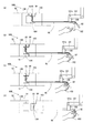
FIG. 1 shows an explanatory view of the
詳述すると、図1(a)は頭部装着状態、すなわち拡大鏡本体10がヘッドギア50に装着され、支持アーム100から分離された状態の脱着型拡大鏡1Aの斜視図を示し、図1(b)はアーム支持状態、すなわち拡大鏡本体10が支持アーム100に装着され、ヘッドギア50から分離された状態の脱着型拡大鏡1Aの斜視図を示している。
More specifically, FIG. 1A shows a perspective view of the
図3(a)は頭部装着状態、すなわち支持アーム100から分離された拡大鏡本体10がヘッドギア50に装着された状態の脱着型拡大鏡1Aの概略図を示し、図3(b)は頭部装着状態からアーム支持状態へと移行する過程の脱着型拡大鏡1Aと支持アーム100との脱着状態、すなわち拡大鏡本体10が支持アーム100に装着され、ヘッドギア50と拡大鏡本体10の連結状態を解除する状態の概略図を示し、図3(c)はアーム支持状態の脱着型拡大鏡1Aの概略図を示している。
FIG. 3A shows a schematic view of a
図4(a)は頭部装着状態、すなわちヘッドギア50に連結された拡大鏡本体10がアーム支持状態へと移行する過程における着脱部を連結する状態のロック機構90の概略図を示し、図4(b)は拡大鏡本体10が支持アーム100に装着された状態のロック機構90の概略図を示し、図4(c)は拡大鏡本体10がヘッドギア50から分離された状態、すなわち連結部を分離した状態のロック機構90の概略図を示し、図4(d)は拡大鏡本体10が支持アーム100から分離する状態、すなわち着脱部を分離する状態のロック機構90の概略図を示している。なお、図4において拡大鏡本体10の図示を省略している。
FIG. 4A shows a schematic view of a
図5(a)は頭部装着状態、すなわち支持アーム100から分離された拡大鏡本体10Bがヘッドギア50に連結された状態の脱着型拡大鏡1Bの概略図を示し、図5(b)は頭部装着状態からアーム支持状態へと移行する過程の脱着型拡大鏡1Bと支持アーム100との脱着状態、すなわち拡大鏡本体10Bが支持アーム100に装着され、ヘッドギア50Bが観察者Mの頭部Hから外れている状態の概略図を示し、図5(c)はアーム支持状態、すなわち拡大鏡本体10Bが支持アーム100に装着され、ヘッドギア50Bが回避された状態の脱着型拡大鏡1Bの概略図を示している。
FIG. 5A shows a schematic view of a
図6(a)は頭部装着状態、すなわちヘッドギア50Bに連結された拡大鏡本体10Bがアーム支持状態へと移行する過程における着脱部を連結する状態のロック機構90Bの概略図を示し、図6(b)は拡大鏡本体10Bが支持アーム100に装着された状態のロック機構90Bの概略図を示し、図6(c)は拡大鏡本体10Bがヘッドギア50Bから分離する状態、すなわち連結部を分離する状態のロック機構90Bの概略図を示し、図6(d)は拡大鏡本体10Bが支持アーム100から分離された状態、すなわち着脱部を分離した状態のロック機構90Bの概略図を示している。なお、図6において拡大鏡本体10Bの図示を省略している。
FIG. 6A shows a schematic view of the
図7(a)は頭部装着状態、すなわち支持アーム100aから分離された拡大鏡本体10Cがヘッドギア50に連結された状態の脱着型拡大鏡1Cの概略図を示し、図7(b)は頭部装着状態からアーム支持状態へと移行する過程の脱着型拡大鏡1Cと支持アーム100aとの脱着状態、すなわち拡大鏡本体10Cが支持アーム100aに装着され、ヘッドギア50Cが観察者Mの頭部Hから外れている状態の概略図を示し、図7(c)はアーム支持状態、すなわち拡大鏡本体10Cが支持アーム100aに装着され、ヘッドギア50Cが回避された状態の脱着型拡大鏡1Cの概略図を示している。
FIG. 7A shows a schematic view of a removable magnifying glass 1C in a state where the magnifying
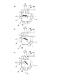
図8(a)は装着方向が調整可能な支持アーム100に支持された状態の脱着型拡大鏡1Dの概略図を示し、図8(b)は支持アーム100に支持された状態で視準方向が調整可能な脱着型拡大鏡1Eの概略図を示し、図8(c)は視準方向の調整を行うための視準方向調整アタッチメント110を備えた支持アーム100bに支持された状態の脱着型拡大鏡1Aの概略図を示している。
FIG. 8A shows a schematic view of the
図9(a)は装着方向が調整可能な支持アーム100に支持された状態の脱着型拡大鏡1Dで水平方向を視準する状態の概略図を示し、図9(b)は脱着型拡大鏡1Dで斜め下方向を視準する状態の概略図を示し、図9(c)は脱着型拡大鏡1Dで下方に視準する状態の概略図を示している。
FIG. 9A shows a schematic view of a state in which the
図10(a)は支持アーム100に支持された状態で視準方向が調整可能な脱着型拡大鏡1Eで直進方向に視準する状態の概略図を示し、図10(b)は脱着型拡大鏡1Eで視準方向を屈曲させて斜め下方に視準する状態の概略図を示し、図10(c)は脱着型拡大鏡1Eで視準方向を屈曲させて下方に視準する状態の概略図を示している。
FIG. 10A shows a schematic view of a state in which the collimation direction is adjustable with the
図11(a)は脱着型拡大鏡1Aが支持アーム100bに支持された状態において視準方向調整アタッチメント110によって直進方向に視準する状態の概略図を示し、図11(b)は視準方向調整アタッチメント110によって視準方向を屈曲させて斜め下方に視準する状態の概略図を示し、図11(c)は視準方向調整アタッチメント110によって視準方向を屈曲させて下方に視準する状態の概略図を示している。
FIG. 11A shows a schematic view of a state in which the
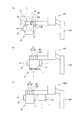
図12(a)はデジタル式脱着型拡大鏡1Fの構成ブロック図を示し、図12(b)は無線デジタル式脱着型拡大鏡1Gの構成ブロック図を示している。図13(a)は支持アーム100に装着されたベース体20から、ヘッドギア50と一体構成した分離体30を分離した状態のデジタル式脱着型拡大鏡1Fの斜視図を示し、図13(b)は頭部装着状態、すなわちヘッドギア50に拡大鏡本体10Fを連結した状態のデジタル式脱着型拡大鏡1Fの斜視図を示している。
FIG. 12A shows a block diagram of the digital
図14(a)はデジタル−アナログ切替式脱着型拡大鏡1Hの平面方向の概略図を示し、図14(b)はデジタル−アナログ併用式脱着型拡大鏡1Jの平面方向の概略図を示している。
図16(a)はHMD1Faの概略斜視図を示し、図16(b)はHUD240aの概略斜視図を示している。
FIG. 14A shows a schematic view of the digital-analog switchable
FIG. 16A shows a schematic perspective view of the HMD1F, and FIG. 16B shows a schematic perspective view of the HUD240a.
脱着型拡大鏡1Aを有する診療ユニットXは、図2に示す歯科診療装置200と、脱着型拡大鏡1Aとともに使用される観察ユニットYとで構成されている。
歯科診療装置200は、図2に示すように、診療器具213(213a〜213e)を備えた器具台210と、施術対象である患者を載せて治療を行うための診療台220とで構成している。
The medical treatment unit X having the
As shown in FIG. 2, the dental
器具台210は、診療台220にアームを介して回動可能に取付けたテーブル211の手前側に器具ホルダ212を備え、器具ホルダ212にエアータービンハンドピース、マイクロモータハンドピースなどの切削工具やスケーラ、スリーウエイシリンジ、バキュームシリンジなどで構成する診療器具213(213a〜213e)を着脱可能に取付けている。
The
また、診療器具213は、水供給源、エア供給源やエア吸引部に接続されて駆動するが、これらの機構については公知であるため、詳細な説明は省略する。
また、各種操作の入力をするためのフートコントローラ214を備えているが、フートコントローラの機構については公知であるため、詳細な説明は省略する。
Further, the
Further, although the
患者を載せる診療台220は、図2に示すように、基台221に昇降可能に載置された座部シートと、その座部シートの後方に連接された傾動可能な背板シート223と、その背板シート223の上端に連接された傾動可能なヘッドレスト224とを備え、これらを診療状況に応じた最適位置に制御するため座部シート昇降部、背板シート傾倒部、ヘッドレスト傾倒部が設けられ、フートコントローラ214によって操作制御された油圧シリンダや電動モータ等の駆動によって駆動するように構成している。
As shown in FIG. 2, the clinic table 220 on which the patient is placed includes a seat seat that is vertically mounted on the
また、診療台220には、スピットン225及び治療用スタンドポール230が付設され、治療用スタンドポール230には、途中より分岐し、回動可能に突出させたアーム231と上端に後述する支持アーム100が備えてられている。アーム231の先端には、診療対象である患者の口腔内等を照明するためのデンタルライト250を備えている。
Further, the clinic table 220 is provided with a
なお、デンタルライト250は、照明用途だけではなく、三次元カメラ(例えば、ステレオカメラ)と一体化されることで、マーカが取り付けられた治療器具や患者の歯の三次元位置を認識する三次元位置検出部260を兼ねていてもよい。
また、治療用スタンドポール230には、モニタ240が設けられている。
The dental light 250 is not only used for lighting, but also integrated with a three-dimensional camera (for example, a stereo camera) to recognize a three-dimensional position of a treatment instrument or a patient's tooth to which a marker is attached. It may also serve as the
Further, the
なお、スピットン225は、口腔内を濯ぐ際などに給水する給水栓と、排唾鉢とを備えている。さらに、患者の背中又は腹部では診療台220に配設された電気系路、油圧系路又はエア系路等と接続する接続部(不図示)が設けられている。
The
また、位置調整可能な支持アーム100(支持部に相当)によって脱着型拡大鏡1Aが支持されている。なお、支持アーム100と脱着型拡大鏡1Aとで観察ユニットYを構成している。
支持アーム100は、診療台220に付設された治療用スタンドポール230の上端に対して回動可能に設けられ、複数のアーム101がそれぞれ可動できるように複数の関節部101aで連結された多関節アーム式であり、支持アーム100の先端に脱着可能に装着された脱着型拡大鏡1Aを、所望の位置に移動可能に構成されている。
Further, the
The
支持アーム100における脱着型拡大鏡1Aの後方には、脱着型拡大鏡1Aを所望の位置に移動させる、つまり多関節アーム式である支持アーム100を構成する各アームの関節部101aを可動させるために観察者M(図3参照)が把持するハンドル102と、脱着型拡大鏡1Aを着脱可能に装着するアーム側着脱部103とを備えている。
In order to move the
観察者Mによって把持されるハンドル102は、繰り返し減菌処理(例えば、高温高圧下のオートクレーブ処理)に耐えうる滅菌可能部材で交換可能に構成されており、使用ごとに滅菌処理されたハンドル102を装着することで、ハンドル102を把持することによる感染対策を図ることができる。
The
このように衛生面の観点から優れたハンドル102としては、膨大な回数の繰り返し減菌処理に耐えうる滅菌可能部材で構成されておらずとも、使用ごとに使い捨てるようにしたり、ある程度の回数だけ滅菌処理に耐えうる部材で構成し、繰り返し滅菌処理による劣化が認められた場合に使い捨てるようにしてもよいし、ハンドル102に対して安価な使い捨てのカバー(例えば、樹脂製のシート等)を装着するように構成してもよい。
脱着型拡大鏡1Aに設けた付替え部13に対して着脱自在に着脱するアーム側着脱部103には、先端側に向かって突出する突出片104(挿し込み部に相当:図3参照)が設けられている。
In this way, the
The arm-side attachment /
また、支持アーム100は、診療台220に付設された治療用スタンドポール230に設けられずとも、天井、壁、あるいは床から延びるように構成されてもよいし、治療用スタンドポール230とは別のスタンド、ワゴン又はラックに設けられてもよい。さらには、スピットン台225、医療用ロボットやその他の医療機器等から延びるように構成されてもよい。
Further, the
このように構成された支持アーム100の先端に脱着可能に構成された脱着型拡大鏡1の一例である脱着型拡大鏡1Aは、図1乃至図3に示すように、観察者Mの頭部に装着するヘッドギア50と支持アーム100とに対して着脱して、付け替え可能に構成されている。
As shown in FIGS. 1 to 3, the
ヘッドギア50は、観察者Mの頭部Hに装着するヘッドギア本体51と、ヘッドギア本体51の正面側に設けられた取付支持部52とで構成されている。
ヘッドギア本体51は、バンド部51aと、装着状態において頭の頂部を介してバンド部51aを前後方向に跨ぐ頂部バンド51bとで構成されている。
The
The headgear
取付支持部52は、上方に延びるとともに、上端から前方に突出する側面視略逆L字型であり、脱着型拡大鏡1Aに設けた付替え部13に対して着脱自在に連結する頭部側連結部53を備えており、頭部側連結部53には、前方に突出する突出片54が設けられている。
The mounting
このように構成されたヘッドギア50の頭部側連結部53に連結してヘッドギア50に連結可能な脱着型拡大鏡1Aの拡大鏡本体10Aは、拡大鏡本体10Aにおける観察部位側、つまり装着状態において観察者Mの前方となる側に設けられた対物レンズ部11と、観察者Mの側、つまり装着状態において観察者Mと対向する側に設けられた接眼レンズ部12(図2、図3参照)と、拡大鏡本体10Aの内部において、対物レンズ部11を介して採光した観察部位の光学像を接眼レンズ部12へ伝送する光学像伝送部(図示省略)と、ヘッドギア50及び支持アーム100に対して付け替える付替え部13とで構成されている。
The magnifying
なお、ヘッドギア50を構成する部材のうち、バンド部51a及び頂部バンド51bをはじめ、頭部Hにフィットする部分を、その他の部分から分離できるよう構成してもよい。例えば、バックルやネジ等の固定機構を用いることで、上述の分離動作が可能となる。これにより、例えば、バンド部51a等が摩耗した場合に新品交換をおこなうことができ、また、長時間使用して観察者の汗等でバンド部51aや頂部バンド51bが汚れてしまった場合に清掃・洗濯することが容易にできるなど、利便性が向上する。
Of the members constituting the
また、バンド部51a及び頂部バンド51b等はヘッドギア50からは分離せずとも、吸汗性のパッドやメッシュシートが、観察者Mの頭部Hにフィットする部分に設けられ、両面テープ、マグネット、あるいはマジックテープ(登録商標)などで着脱できるように構成されていてもよい。
Further, even if the
なお、拡大鏡本体10Aは、観察部位を観察する拡大鏡であり、上述の光学像伝送部をレンズ等の光学部材で構成したアナログ式であってもよいし、後述するようなデジタル式であってもよい。上記観察部位は、歯牙や歯牙内部、あるいは歯肉など口腔内の部位や、人間や動物の体の一部であってもよい。
The magnifying
付替え部13は、拡大鏡本体10Aの上部略中央に設けられており、対物レンズ部11側に設けられ、上述のアーム側着脱部103に対して着脱自在に着脱する本体側着脱部14と、接眼レンズ部12側に設けられ、上述の頭部側連結部53に対して着脱自在に連結する本体側連結部15とで構成されている(図3参照)。
The
本体側着脱部14は、アーム側着脱部103が挿入される挿入空間141と、突出片104が挿し込まれ、装着状態を固定する凹状の挿込固定凹部142とを有している(図1参照)。
本体側連結部15は、図3(c)に示すように、頭部側連結部53が挿入される挿入空間151と、突出片54が挿し込まれ、連結状態を固定する凹状の挿込固定凹部152とを有している。
The main body side attachment /
As shown in FIG. 3C, the main body
このように構成された付替え部13における本体側着脱部14に対してアーム側着脱部103を嵌合することで脱着型拡大鏡1Aを支持アーム100に対して装着して、脱着型拡大鏡1Aを支持アーム100で支持することができる。また、本体側連結部15に対して頭部側連結部53を嵌合することで脱着型拡大鏡1Aをヘッドギア50に対して連結することができる。つまり、脱着型拡大鏡1Aにおいて、拡大鏡本体10Aの全体が分離部として機能している。
The
このように構成された脱着型拡大鏡1Aを、ヘッドギア50と支持アーム100に付け替える付け替え動作について図3とともに説明する。
図3(a)に示すように、頭部Hに装着したヘッドギア50に脱着型拡大鏡1Aを装着した観察者Mがハンドル102を把持して、アーム側着脱部103を頭部Hに装着した脱着型拡大鏡1Aの本体側着脱部14に挿入するように支持アーム100を移動させる。そして、図3(b)に示すように、支持アーム100の先端に設けたアーム側着脱部103を本体側着脱部14に嵌合させる。
The replacement operation of replacing the
As shown in FIG. 3A, an observer M who attached the
このように、アーム側着脱部103を本体側着脱部14に嵌合させてから、脱着型拡大鏡1Aの本体側連結部15とヘッドギア50の頭部側連結部53との嵌合を解放することで、図3(c)に示すように、脱着型拡大鏡1Aを支持アーム100に付け替えて支持アーム100で支持することができる。
なお、支持アーム100に支持された脱着型拡大鏡1Aをヘッドギア50に付け替える場合は、上述の説明の逆の動作を行うとよい。
In this way, after the arm-side attachment /
When replacing the
このように、支持アーム100に支持され、観察部位を観察する拡大鏡本体10Aと、観察者Mの頭部Hに装着するヘッドギア50とが備えられ、拡大鏡本体10Aは、観察部位側の対物レンズ部11、観察者Mの側の接眼レンズ部12、並びに対物レンズ部11を介して採光した観察部位の光学像を接眼レンズ部12へと伝送する光学像伝送部で構成されるとともに、拡大鏡本体10Aを分離部として支持アーム100から着脱する着脱部14,103と、拡大鏡本体10Aをヘッドギア50に着脱可能に連結する連結部15,53とが設けられた脱着型拡大鏡1Aは、観察部位を、支持アーム100に支持された状態の拡大鏡本体10Aで観察したり、頭部Hに装着した状態の拡大鏡本体10Aで観察したりすることができる。
In this way, the magnifying
詳述すると、観察部位を観察する拡大鏡本体10Aと、観察者Mの頭部Hに装着するヘッドギア50とが備えられ、拡大鏡本体10Aは、観察部位側の対物レンズ部11、観察者Mの側の接眼レンズ部12、並びに対物レンズ部11を介して採光した観察部位の光学像を接眼レンズ部12へと伝送する光学像伝送部で構成されるとともに、接眼レンズ部12を含む拡大鏡本体10Aを分離部として支持アーム100から着脱する着脱部14,103とが備えられているため、脱着型拡大鏡1Aを支持する支持アーム100から分離部として拡大鏡本体10Aを取り外すことができる。
More specifically, the magnifying glass
また、観察者Mの頭部Hに装着するヘッドギア50に対して、分離部である拡大鏡本体10Aを着脱可能に連結する連結部15,53を備えているため、着脱部14,103によって、支持アーム100から取り外された拡大鏡本体10Aを観察者Mの頭部Hに装着するヘッドギア50に連結することができる。
Further, since the
したがって、観察者Mは、観察部位を、支持アーム100に支持された状態の拡大鏡本体10Aで負担なく観察したり、頭部Hに装着した状態の拡大鏡本体10Aで、頭部Hの移動が規制されることなく観察したりすることができ、利便性や操作性を向上することができる。
Therefore, the observer M observes the observation site with the magnifying glass
また、本体側着脱部14とアーム側着脱部103とで構成する着脱部において、本体側着脱部14の挿込固定凹部142に挿し込む突出片104をアーム側着脱部103に備えているため、突出片104を本体側着脱部14の挿込固定凹部142に挿し込むことで着脱部14,103を装着し、拡大鏡本体10Aを支持アーム100で支持することができる。したがって、観察者Mは、ヘッドギア50に触れることなく着脱でき、衛生的であるため、感染予防等に貢献することができる。
Further, in the attachment / detachment portion composed of the main body side attachment /
なお、挿込固定凹部をアーム側着脱部103に備え、挿込固定凹部に挿し込む突出片を本体側着脱部14に備えてもよい。
The insertion / fixing recess may be provided in the arm-side attachment /
また、支持アーム100が、観察部位に対して移動可能に構成されているため、支持アーム100を観察部位に対して適切な位置に配置してから観察できるため、より詳細に観察することができる。
詳述すると、上述のように、支持アーム100に関節部101aを有し、関節部101aの動きによって支持アーム100が観察部位に対して移動可能に構成されているため、関節部101aで曲げて支持アーム100で支持する拡大鏡本体10Aを、観察部位に対してより適切な位置に配置してから観察できるため、より詳細に観察することができる。
なお、関節部101aは少なくともひとつあればよく、複数あってもよい。
Further, since the
More specifically, as described above, since the
It should be noted that there may be at least one
また、付替え部13における本体側着脱部14や本体側連結部15に嵌合するアーム側着脱部103及び頭部側連結部53には、例えば、後述するように、挿込固定凹部142,152に対する突出片104,54に挿し込みをロックするロック機構90を備えてもよい。
Further, as described later, for example, the insertion /
なお、挿込固定凹部142,152に対する突出片104,54に挿し込みをロックするロック機構90は、挿込固定凹部142に対して突出片104が挿し込みされたことによって、挿込固定凹部152に対する突出片54の挿し込み状態を解除する構成である。
The
上述したロック機構90の例として、プランジャ93を用いた構成を、図4を用いて説明する。
アーム側着脱部103と頭部側連結部53には下部が円柱で上部を円錐状のツメとして形成されたプランジャ93が内蔵されており、バネ94の作用によりプランジャ93の先端にあるツメが飛び出たり、押しこまれたりするように構成されている。付替え部13にはツメと対応した溝があり、ツメが飛び出ているときにはツメが溝の壁面に引っ掛かり、着脱できないようロックされる。逆に、ツメが押し込まれているときにはロックが解除され、着脱可能となる。
As an example of the
A
例えば、図4(a)を参照すると、ここでは頭部装着状態、すなわちヘッドギア50に連結された拡大鏡本体10がアーム支持状態へと移行する過程における着脱部を連結する状態のロック機構90の概略図を示しており、頭部側連結部53側のプランジャ93のツメが付替え部13の溝に引っ掛かりロックされた状態となっている。
For example, referring to FIG. 4A, here, the
付替え部13の溝内部にはシーソー構造91が備わっており、アーム側着脱部103に内蔵されたプランジャ93は頭部側連結部53に内蔵されたものよりも強いばねが採用されている。よって、図4(b)のように頭部側連結部53とアーム側着脱部103の両方が付替え部13に対して挿しこまれた状態においては、自然状態では、シーソー構造91の作用によって弱いバネ94が採用されている頭部側連結部53の側のプランジャ93のツメは押し込まれ、アーム側着脱部103の側のプランジャ93のツメが飛び出す。すなわち、図4(b),(c)に示すように、アーム側着脱部103が付替え部13に対してロックされ、頭部側連結部53が付替え部13に対してロックが解除され自由に着脱可能な状態となる。
A
ここでアーム側着脱部103のほうのプランジャ93にはワイヤー95が接続されており、ワイヤー95の反対側はワイヤー95を操作するためのレバー92と接続されている。図4(d)に示すように、観察者Mがレバー92を握ることでワイヤー95が引っ張られ、アーム側着脱部103に内蔵されたプランジャ93のツメが押し込まれる。するとシーソー構造91と頭部側連結部53の側のプランジャ93のバネ94の作用により、頭部側連結部53の側のツメが飛び出す。なお、プランジャ93が収納されているプランジャ93が出没する凹部の内径は、プランジャ93の外径よりも小さいのでプランジャ93が凹部から飛び出すことはない。
Here, the
すなわち、頭部側連結部53が付替え部13に対してロックされ、アーム側着脱部103が付替え部13に対してロックが解除され自由に着脱可能な状態となる。このように観察者Mはレバー92の操作によってロック/ロック解除の状態を選択でき、利便性が向上する。なお、レバー92はハンドル102の付近に設置されているため、支持アーム100を可動させるための操作と、ロック/ロック解除の操作とで、観察者Mの手の位置を同一とすることができ、操作性が向上する。また感染対策としてレバー92の手で触れる箇所を、交換可能な滅菌可能部材としたり、使い捨てのカバーをかぶせて使用したりすることで、衛生的な操作が可能となる。
That is, the head-
ロック機構90を操作する手段としてレバー92を例示したがこれに限らず、ボタン等であってもよい。また、ワイヤー95の引っ張り操作とプランジャ93を用いてツメの飛び出し状態を操作する機構を例示したが、サイドリリースバックルのように、弾性を有した梁構造によって、梁構造の先端に設けられたツメを可動とし、梁構造を押すことでツメの可動状態を操作できるような機構でもよい。また、円柱状のプランジャの代わりにボールプランジャを用いてもよい。
The
また、ワイヤー95やシーソー構造91を用いて手動で機械的にロック状態を操作する例を示したが、電動的手段(例えば、アクチュエータや電磁石の力でツメの可動を操作したり、モータの回転でワイヤー95を巻き取ったりするなど)で操作できるようにしてもよく、電動的手段とすることで、ロック機構90を操作するためレバー・ボタン等を、付替え部13から遠隔の位置に設置することが容易となり(例えば、フートコントローラやタッチパネルでロック機構90を操作できる)、さらに利便性が向上する。
Further, although an example of manually and mechanically operating the locked state by using a
また、シーソー構造91を介することで、1つのレバー92で2つのツメを操作する構成を示したが、シーソー構造91に限らず、2つのツメが連動して動作する構造であれば何でもよく、歯車、ワイヤー、バネ、あるいはアクチュエータ、さらにこれらの組み合わせ等によって構成されていてもよい。あるいは、頭部側連結部53の側のプランジャ93を操作するレバー92等と、アーム側着脱部103の側のプランジャ93を操作するレバー92等とが、別々に設けられており、それぞれのロック状態を別々に操作できるよう構成されていてもよい。また、図4ではプランジャ93の先端のツメを角張ったように描いているが、丸みを帯びていてもよい。
Further, although the configuration in which two claws are operated by one
このように、付替え部13における本体側着脱部14や本体側連結部15に嵌合するアーム側着脱部103及び頭部側連結部53に、挿込固定凹部142,152に対する突出片104,54に挿し込みをロックするロック機構90を備えることによって、上述する付替え部13における本体側着脱部14や本体側連結部15に対するアーム側着脱部103及び頭部側連結部53の嵌合状態をロックすることができる。
In this way, the protruding
さらに、挿込固定凹部142,152に対する突出片104,54に挿し込みをロックするロック機構90は、挿込固定凹部142に対して突出片104が挿し込みされたことによって、挿込固定凹部152に対する突出片54の挿し込み状態を解除する構成であり、挿込固定凹部152に対して突出片54が挿し込みされたことによって、挿込固定凹部142に対する突出片104の挿し込み状態を解除する構成であるため、拡大鏡本体10Aを、支持アーム100とヘッドギア50とに対して安全に付け替えることができる。
Further, the
上述の脱着型拡大鏡1Aはヘッドギア50と別体で構成し、ヘッドギア50と支持アーム100に付け替えたが、脱着型拡大鏡1の別の例として、ヘッドギア50Bと一体構成され、全体が分離部として機能する脱着型拡大鏡1Bについて、図5とともに説明する。
図5に示す脱着型拡大鏡1Bは、ヘッドギア50Bと拡大鏡本体10Bとが連結されており、一体構成されている。
The above-mentioned
The
ヘッドギア50Bは、上述のヘッドギア50のヘッドギア本体51と同じ構成であるが、自立可能な形状保持性を有する素材で構成されている。
また、ヘッドギア50Bは、図示省略するサイズ調整部によって、図5(b)に示すように、拡縮可能に構成されている。なお、サイズ調整部としては、図示省略する回転操作部を操作することによって、ヘッドギア本体51を構成するバンド部51aの周長を拡縮するように構成することができる。
The
Further, the
また、上述の脱着型拡大鏡1Aでは、拡大鏡本体10Bの付替え部13に設けられた本体側連結部15で、ヘッドギア50の頭部側連結部53と着脱可能に連結したが、脱着型拡大鏡1Bの拡大鏡本体10Bに備えられた付替え部13Bは、本体側着脱部14を設けられているものの本体側連結部15の代わりに取付支持部52に対して回転可能に連結される回転連結部16が設けられている。
Further, in the above-mentioned
回転連結部16は、拡大鏡本体10Bとヘッドギア50Bとを水平軸を中心に回転可能に連結されている。詳しくは、少なくとも、図5(a)に示すように拡大鏡本体10Bとヘッドギア50Bとが並ぶ状態と、図5(c)に示すような拡大鏡本体10Bとヘッドギア50Bとが直角方向となる状態を維持できるように回転可能に連結されている。
The
このように構成された脱着型拡大鏡1Bを付け替えするためには、図5(a)に示すように、頭部Hに装着した脱着型拡大鏡1Bを装着した観察者Mがハンドル102を把持して、アーム側着脱部103を頭部Hに装着した脱着型拡大鏡1Bの本体側着脱部14に挿入するように支持アーム100を移動させる。そして、図5(b)に示すように、支持アーム100の先端に設けたアーム側着脱部103を本体側着脱部14に嵌合させるとともに、ヘッドギア50Bを図示省略するサイズ調整部を調整して、頭部Hに対してヘッドギア50Bを拡大調整する。
In order to replace the
このように、ヘッドギア50Bを拡大調整してから、回転連結部16によって、ヘッドギア50Bが上方となるように、ヘッドギア50Bを回転移動させることで、図5(c)に示すように、脱着型拡大鏡1Bを支持アーム100に付け替えて支持アーム100で支持することができる。
In this way, after the
また、拡大鏡本体10Bに対して、頭部Hに未装着のヘッドギア50Bを回避させる回転連結部16が備えられているため、ヘッドギア50Bが支障することなく、支持アーム100で支持された状態の拡大鏡本体10Bで観察部位を観察することができる。
Further, since the magnifying glass
したがって、観察者Mは、観察部位を、支持アーム100に支持された状態の拡大鏡本体10Bで負担なく観察したり、頭部Hに装着した状態の拡大鏡本体10Bで、頭部Hの移動が規制されることなく観察したりすることができ、利便性や操作性を向上することができる。
Therefore, the observer M observes the observation site with the magnifying
なお、サイズ調整部は、上述のような手動の回転操作にもよらず、例えば、ハンドル102の付近やフートコントローラに操作スイッチやレバーを設け、アーム側着脱部103を本体側着脱部14に嵌合させてからの操作スイッチ等の操作によって、モータ駆動や空気の充填、あるいは付勢体の付勢力によって自動的にサイズ調整可能に構成してもよい。
The size adjusting unit is provided with an operation switch or lever near the
サイズ調整部の別の例として、回転操作部を用いて手動でヘッドギア50Bのサイズ調整を行う場合には、感染予防等の観点から、回転操作部のうち手で触れる箇所を交換可能な滅菌可能部材で構成するか、使い捨てのカバーをかぶせて使用ことが好ましい。
As another example of the size adjustment unit, when the size of the
さらには、回転連結部16を介したヘッドギア50Bの回転移動は、例えば、観察者Mの手が触れる箇所を交換可能な滅菌可能部材で構成した回転操作部をヘッドギア本体51に設け、上記回転操作部を把持することでヘッドギア50Bを回転移動させる等の手動で回転移動させてもよいし、アーム側着脱部103を本体側着脱部14に嵌合させてからのハンドル102に設けた操作スイッチの操作によって、モータ駆動や空気の充填、あるいは付勢体の付勢力によって自動的にヘッドギア50Bを回転移動するように構成してもよい。
Further, for the rotational movement of the
上記により、観察者Mはヘッドギア50Bに触れることなく、あるいは滅菌可能部材等で感染対策がされた箇所以外の不要な箇所に手で触れることなくアーム支持状態と頭部装着状態とを遷移でき、衛生的であるため、感染予防等に貢献することができる。
According to the above, the observer M can transition between the arm support state and the head-mounted state without touching the
また、図6に示すように、アーム側着脱部103と本体側着脱部14との嵌合状態をロックするロック機構90Bを備えてもよい。ロック機構90Bの例として、プランジャ93を用いた機構を採用してもよい。ここでは、図4に図示するロック機構90の構成と比べ、シーソー構造91と、頭部側連結部53の側のプランジャ93とが省かれた構成であり、その他の構造は同一であるため詳細な説明は省略する。
Further, as shown in FIG. 6, a
図6におけるロック機構90Bは、図4に図示するロック機構90の構成と同様に、レバー92を握ることで、ワイヤー95が引っ張られ、プランジャ93の先端のツメがアーム側着脱部103の内部に押しこまれる方向に可動し、アーム側着脱部103と付替え部13Bのロック状態が解除され、反対にレバー92を離すと、プランジャ93のバネ94の作用により、アーム側着脱部103が付替え部13Bの本体側着脱部14に対してロックされる。
In the
あるいは、図4に図示するロック機構90にあるようなシーソー構造91をロック機構90Bにも備え、シーソー構造91のうち、アーム側着脱部103の側のプランジャ93と接触する部分とは反対側の端が動作することにより、特定の操作スイッチ等が押され、例えば、サイズ調整部や回転連結部が作動するように構成してもよい。
Alternatively, the
脱着型拡大鏡1の別の例として、図7に示すように、形状保持性のないヘッドギア50Cと拡大鏡本体10Cとを一体構成して、全体が分離部として機能する脱着型拡大鏡1Cを構成してもよい。脱着型拡大鏡1Cを構成するヘッドギア50Cは、バンド部51aと頂部バンド51bとを可撓性のある変形可能な紐状体で構成しており、図示省略するサイズ調整部を調整して、頭部Hに対してヘッドギア50Cを拡縮調整可能に構成されている。
As another example of the
そのため、頭部Hへの装着後、サイズ調整部を調整して、紐状体で構成したバンド部51a及び頂部バンド51bの長さを調整して、頭部Hにフィットさせるようにして、ヘッドギア50Cを頭部Hに装着することができる。
Therefore, after mounting on the head H, the size adjusting portion is adjusted to adjust the lengths of the
また、図7に示した脱着型拡大鏡1Cの拡大鏡本体10Cに備えられた付替え部13Cは、本体側着脱部14を設けているものの、図3に示したような本体側連結部15も、図5に示したような回転連結部16も設けられておらず、一方で観察者Mにとって後方となる本体側連結部15aと頂部バンド51bとの交点に、頭部側連結部53Cが備えられており、頭部側連結部53Cには、頭部Hへの装着状態において後方に突出する突出片54Cが設けられている。なお、この頭部側連結部53Cに、上述のサイズ調整部を設けてもよい。
Further, although the
また脱着型拡大鏡1Cを観察者Mの頭部Hへの装着状態から付け替えて支持する支持アーム100aには、アーム側着脱部103の上方に、頭部側連結部53Cが嵌合する本体側連結部15Cを備えている。詳しくは、アーム側着脱部103の背後に鉛直方向上方に延びる支柱151Cが設けられており、支柱151Cの上端に挿込固定凹部152Cが設けられて本体側連結部15Cが構成されている。
Further, the
このように構成した脱着型拡大鏡1Cを付け替えるためには、図7(a)に示すように、頭部Hに装着した脱着型拡大鏡1Cを装着した観察者Mがハンドル102を把持して、アーム側着脱部103を頭部Hに装着した状態の脱着型拡大鏡1Cの本体側着脱部14に挿入するように支持アーム100aを移動させる。そして、図7(b)に示すように、支持アーム100aの先端に設けたアーム側着脱部103を本体側着脱部14に嵌合させるとともに、ヘッドギア50Cを図示省略するサイズ調整部を調整して、頭部Hに対してヘッドギア50Cを拡大調整する。
In order to replace the removable magnifying glass 1C configured in this way, as shown in FIG. 7A, the observer M wearing the removable magnifying glass 1C attached to the head H grips the
このように、ヘッドギア50Cを拡大調整してから、ヘッドギア本体51Cを構成する紐状体を変形させ、頭部側連結部53Cを挿込固定凹部152cと嵌合させることで、図7(c)に示すように、脱着型拡大鏡1Cを支持アーム100aに付け替えて支持アーム100aで支持することができる。
In this way, after the
また、観察者Mは、拡大鏡本体10Cに対して、頭部Hに未装着のヘッドギア50Cを回避させる構造(53C、54C、15C、152C)が備えられているため、ヘッドギア50Cが支障することなく、支持アーム100aで支持された状態の拡大鏡本体10Cで観察することができる。
Further, since the observer M is provided with a structure (53C, 54C, 15C, 152C) for avoiding the
また観察者Mは、観察部位を、支持アーム100aに支持された状態の拡大鏡本体10Cで負担なく観察したり、頭部Hに装着した状態の拡大鏡本体10Cで、頭部Hの移動が規制されることなく観察したりすることができ、利便性や操作性を向上することができる。
Further, the observer M observes the observation site with the magnifying glass
なお、サイズ調整部は、上述のような手動の回転操作にもよらず、例えば、ハンドル102の付近やフートコントローラに操作スイッチやレバーを設け、アーム側着脱部103を本体側着脱部14に嵌合させてからの操作スイッチの操作によって、モータ駆動や空気の充填、あるいは付勢体の付勢力によって自動的にサイズ調整可能に構成してもよい。
The size adjusting unit is provided with an operation switch or lever near the
また、サイズ調整部である回転調整部を頭部側連結部53Cに設け、該回転調整部のうち手で触れる箇所を交換可能な滅菌可能部材で構成し、該回転操作部を把持することで突出片54Cを挿込固定凹部152Cの位置にまで移動させ嵌合するようにしてもよい。
Further, a rotation adjusting portion, which is a size adjusting portion, is provided on the head
上記により、観察者Mはヘッドギア50Cのうち、滅菌可能部材等で感染対策がされた箇所以外の不要な箇所に手で触れることなくアーム支持状態と頭部装着状態とを移行でき、衛生的であるため、感染予防等に貢献することができる。
As a result, the observer M can switch between the arm-supported state and the head-mounted state without touching unnecessary parts of the
なお、ここまでの説明や図においては、突出片104、54、54Cが凸形状であり、挿込固定凹部142、152、152Cが凹形状であるように説明しているが、嵌合する関係にある部材の凹凸形状は逆であってもよい。例えば、アーム側着脱部103の先端が凹形状であり、それと嵌合する本体側着脱部14が凸形状に形成してもよい。
In the above description and drawings, the protruding
このように、脱着型拡大鏡1A,1B,1Cは、頭部Hと支持アーム100とに付け替えすることで、頭部Hに装着する状態と支持アーム100で支持する状態とを切り替え、所望の状態で観察者Mは観察できるが、支持アーム100に支持された状態で、視準方向を調整できる脱着型拡大鏡1について以下で説明する。
In this way, the
支持アーム100で支持された状態で脱着型拡大鏡1による視準方向を調整するためには、例えば、図8に示すような3種類の脱着型拡大鏡1(1D,1E,1A)がある。図8(a)に示す脱着型拡大鏡1Dは、支持アーム100に支持された状態で、装着角度を調整することで視準方向を調整し、図8(b)に示す脱着型拡大鏡1Eは、支持アーム100に支持された状態で、拡大鏡本体10Eに設けた視準方向調整部によって視準方向を調整し、図8(c)に示す脱着型拡大鏡1Aは、支持アーム100bに支持された状態で、支持アーム100bに設けた視準方向調整アタッチメント110によって視準方向を調整するように構成している。
なお、以下でそれぞれの視準方向の調整について、詳細に説明するが、あくまでもこれらの3種類の視準方向調整方法は例示であり、これらに限定されるものではない。
In order to adjust the collimation direction by the
The adjustment of each collimation direction will be described in detail below, but these three types of collimation direction adjustment methods are merely examples and are not limited thereto.
図8(a)及び図9に示す脱着型拡大鏡1Dは、付替え部13Dにおける本体側着脱部14Dに角度調整部17を設けている。角度調整部17は、ラチェット式で任意の角度に固定でき、所定の力を作用させることで、角度を調整可能に構成されている。
In the
例えば、脱着型拡大鏡1Dで水平方向に視準する場合は、図9(a)に示すように、支持アーム100で支持された状態において、対物レンズ部11と接眼レンズ部12とが水平となるように角度調整部17を調整し、支持アーム100に対する装着角度を調整する。
For example, when collimating in the horizontal direction with the
これに対し、例えば、脱着型拡大鏡1Dで斜め下方向を視準する場合は、図9(b)に示すように、支持アーム100で支持された状態において、接眼レンズ部12に対して対物レンズ部11が斜め下方となるように角度調整部17を調整し、支持アーム100に対する装着角度を調整する。
On the other hand, for example, when collimating diagonally downward with the
また、例えば、脱着型拡大鏡1Dで下方向を視準する場合は、図9(c)に示すように、支持アーム100で支持された状態において、接眼レンズ部12に対して対物レンズ部11が下方となるように角度調整部17を調整し、支持アーム100に対する装着角度を調整する。
Further, for example, when collimating the downward direction with the
このように、脱着型拡大鏡1Dでは、支持アーム100による支持状態で、角度調整部17によって、脱着型拡大鏡1Dの支持アーム100に対する装着角度を調整することで、脱着型拡大鏡1Dによって視準する視準方向を任意の方向に調整することができる。
As described above, in the
このように、接眼レンズ部12から対物レンズ部11を介して観察する視準方向を調整するために、脱着型拡大鏡1Dは、支持アーム100に対する装着角度を調整する角度調整部17を拡大鏡本体10Dに備えており、角度調整部17によって接眼レンズ部12から対物レンズ部11を介して観察する視準方向を調整することができ、拡大鏡本体10Dをヘッドギア50に連結した状態と、拡大鏡本体10Dを支持アーム100で支持した状態とにおいて、それぞれの状態において適した視準方向で観察することができ、操作性をさらに向上することができる。
In this way, in order to adjust the collimation direction observed from the
視準方向を調整するための別の構成として、図8(b)及び図10に示す脱着型拡大鏡1Eは、拡大鏡本体10Eに、接眼レンズ部12に対する対物レンズ部11の方向を調整する視準方向調整部を設けている。視準方向調整部は、接眼レンズ部12に対する対物レンズ部11の位置を調整するとともに、対物レンズ部11から入光した光学像を接眼レンズ部12に向かうように光路を調整する調整ミラー18を内蔵しており、調整ミラー18は、接眼レンズ部12に対する対物レンズ部11の位置調整に伴って調整ミラー18の向きが調整されるように構成されている。
As another configuration for adjusting the collimation direction, the
例えば、脱着型拡大鏡1Eで水平方向に視準する場合は、図10(a)に示すように、支持アーム100で支持された状態において、接眼レンズ部12に対して対物レンズ部11が水平となるように位置調整される。このとき、調整ミラー18は、対物レンズ部11から入光した光学像はそのまま接眼レンズ部12を通るため、調整ミラー18は、光学像が通る領域外に回避している。
For example, when collimating in the horizontal direction with the
これに対し、例えば、脱着型拡大鏡1Eで斜め下方向を視準する場合は、図10(b)に示すように、接眼レンズ部12に対して対物レンズ部11が斜め下方となるように位置調整されるとともに、対物レンズ部11の位置調整に伴って移動した調整ミラー18によって、対物レンズ部11から入光した光学像の進行方向は斜め上向きの方向から水平方向に屈曲し、接眼レンズ部12を通るようになる。
On the other hand, for example, when collimating diagonally downward with the
また、例えば、脱着型拡大鏡1Eで下方向を視準する場合は、図10(c)に示すように、接眼レンズ部12に対して対物レンズ部11が下方となるように位置調整されるとともに、対物レンズ部11の位置調整に伴って移動した調整ミラー18によって、対物レンズ部11から入光した光学像の進行方向は上向きの方向から水平方向に屈曲され、接眼レンズ部12を通るようになる。
Further, for example, when collimating downward with the
このように、脱着型拡大鏡1Eでは、支持アーム100による支持状態で、接眼レンズ部12に対する対物レンズ部11の位置を調整するとともに、対物レンズ部11の位置調整に伴って移動する調整ミラー18によって、対物レンズ部11から入光した光学像はその進行方向を水平方向に調整され、接眼レンズ部12を通るように調整することができる。
As described above, in the
このように、接眼レンズ部12から対物レンズ部11を介して観察する視準方向を調整する調整ミラー18を備えた拡大鏡本体10Eは、調整ミラー18によって接眼レンズ部12から対物レンズ部11を介して観察する視準方向を調整することができ、拡大鏡本体10Eをヘッドギア50に連結した状態と、拡大鏡本体10Eを支持アーム100で支持した状態とにおいて、それぞれの状態において適した視準方向で観察することができ、操作性をさらに向上することができる。
In this way, the magnifying
視準方向を調整するための別の構成として、図8(c)及び図11に示す脱着型拡大鏡1Aが装着される支持アーム100bは、装着された拡大鏡本体10の前方に視準方向調整アタッチメント110が設けられており、脱着型拡大鏡1Aは、視準方向調整アタッチメント110を介して観察部位を観察するように構成されている。
As another configuration for adjusting the collimation direction, the
なお、視準方向調整アタッチメント110には、接眼レンズ部12に対する対物レンズ部11の視準方向を調整する視準方向調整部と機能する方向調整ミラー111が設けられており、図示省略する操作部によって、その配向方向を調整可能に構成されている。
The collimation
例えば、脱着型拡大鏡1Aで水平方向に視準する場合は、図11(a)に示すように、支持アーム100bで支持された状態において、視準方向調整アタッチメント110を経由した光学像はそのまま対物レンズ部11に入光されるため、方向調整ミラー111は、光学像が通る領域外に回避している。
For example, when collimating in the horizontal direction with the
これに対し、例えば、脱着型拡大鏡1Aで斜め下方向を視準する場合は、図11(b)に示すように、斜め下方から視準方向調整アタッチメント110へと入光する光学像を対物レンズ部11に入光されるように位置調整された方向調整ミラー111を経由させることによって、光学像の進行方向が水平方向に屈曲し、対物レンズ部11から入光されるようになる。
On the other hand, for example, when collimating diagonally downward with the
また、例えば、脱着型拡大鏡1Aで下方向を視準する場合は、図11(c)に示すように、下方から視準方向調整アタッチメント110へと入光する光学像を対物レンズ部11に入光されるように位置調整された方向調整ミラー111を経由させることによって、光学像の進行方向が水平方向に屈曲され、対物レンズ部11から入光されるようになる。
Further, for example, when collimating the downward direction with the
このように、図11に示した脱着型拡大鏡1Aでは、支持アーム100bによる支持状態で、視準方向調整アタッチメント110における方向調整ミラー111の位置調整によって、さまざまな視準方向にある観察部位の光学像を対物レンズ部11から入光するように調整することができる。
As described above, in the
また、視準方向調整アタッチメント110は、対物レンズ部11と観察部位との間の位置にあり、支持アーム100bに対して固定されており、すなわち、脱着型拡大鏡1Aの外部に設置された追加の光学系であり、拡大鏡本体10Aによる視準方向を調整する視準方向調整部として機能しているが、上記追加の光学系には、視準方向調整アタッチメント110以外の光学素子や、上記を組み合わせたものであってもよい。例えば、カバーガラス、カラーフィルタ、照明用光源などの光学素子や、後述する倍率変換レンズであってもよい。上記追加の光学系を備えることにより、脱着型拡大鏡1Aで観察する観察視野に対して、観察内容に応じてより適切に観察することができる。
Further, the collimation
上記追加の光学系に含まれる光学素子の例として、例えば、観察部位を観察する際の拡大倍率を変換する倍率変換レンズ(図示省略)が備えられてもよい。上記倍率変換レンズを経由した光学像を脱着型拡大鏡1Aを通して観察することで、倍率変換レンズを経由しない場合とは異なる拡大倍率にて、観察部位を観察することができる。また、倍率変換レンズとしてズーム式やリボルバー式の倍率可変レンズとすることで、さまざまな拡大倍率の中から所望の倍率を選択して、観察部位を観察することができる。
As an example of the optical element included in the additional optical system, for example, a magnification conversion lens (not shown) that converts the magnification when observing the observation site may be provided. By observing the optical image via the magnification conversion lens through the
ここで、上記ズーム式・リボルバー式といった機構を有する倍率変換レンズや、方向調整ミラーを駆動する調整機構を有する視準方向調整アタッチメント110は一般に重量が大きくなるが、当該倍率変換レンズは支持アーム100bに対して固定されているため、支持アーム100bから分離して頭部に装着する部分(分離部)の重量増加には寄与しないため問題とはならない。
Here, the magnification conversion lens having a mechanism such as the zoom type and the revolver type and the collimation
具体的には、視準方向の調整や、レンズの拡大倍率を高倍率に設定しての観察動作は、拡大鏡本体10を支持アーム100bに固定した状態でのみに必要であることが多い。例えば、頭部Hに装着した状態の拡大鏡本体10を使用する際にレンズの拡大倍率を高倍率としてしまうと、観察者Mの視界が極端に小さくなり、頭を動かした際に周囲の障害物に気づかず、障害物に頭部Hが接触するなどの危険があるため、ある程度の広さの視野を確保できる低倍率とした方が有利である。
Specifically, the adjustment of the collimation direction and the observation operation with the magnifying glass of the lens set to a high magnifying glass are often required only in the state where the magnifying glass
また、脱着型拡大鏡1Aを頭部Hに装着した状態では、頭部Hを動かせば視準方向もそれに応じて自由に可動するため、方向調整ミラー等は設けなくとも十分である。すなわち、この構成により、分離部として支持アーム100bから分離した頭部Hに装着する部分の構成が最低限、すなわち小型軽量となり、操作性を向上することができ、観察者の満足度と安全性も向上する。
Further, when the
これまで説明した脱着型拡大鏡1は、上述したようにアナログ式の拡大鏡であっても、デジタル式の拡大鏡であってもよいが、以下において、デジタル式であり、接眼レンズ部12が分離部として拡大鏡本体10Fから分離されるデジタル式脱着型拡大鏡1Fについて、図12(a)及び図13とともに説明する。
The
デジタル式脱着型拡大鏡1Fは、図12(a)及び図13に示すように、拡大鏡本体10Fと、制御部60と、バッテリ70とで構成されている。拡大鏡本体10Fは、対物レンズ部11を有するベース体20と、接眼レンズ部12を有する分離体30とで構成されており、ベース体20と分離体30とを脱着可能に連結する分離連結部40を備えている。また、後述するように、ベース体20と分離体30とは、図示省略する通信部によって制御部60を介して接続されている。
As shown in FIGS. 12A and 13, the digital
ベース体20は、分離連結部40によって分離体30の前方に脱着可能に連結され、対物レンズ部11と、本体側着脱部14Eと、後述する分離側連結部42とで分離連結部40を構成するベース側連結部41を備えている。本体側着脱部14Eの嵌合に関する構成は、脱着型拡大鏡1Aにおける本体側着脱部14と同様の構成であるが、デジタル式である脱着型拡大鏡1Eは駆動するための電力が必要であるため、アーム側着脱部103に嵌合された状態で、支持アーム100からバッテリ70を備えたベース体20へと電力が供給されるように構成されている。
The
また、後述する分離側連結部42とで分離連結部40を構成するベース側連結部41は、分離側連結部42と嵌合することで連結可能であり、頭部側連結部53と嵌合する本体側連結部15と同様の嵌合構造で構成されているが、本体側着脱部14Eと同様に、本体側着脱部14Eを介して供給された電力を分離体30に供給可能に構成している。
Further, the base
また、ベース体20は、対物レンズ部11に、観察部位の光学像を光学情報として検出するイメージセンサで構成するカメラ21(撮像部に相当。例えば、可視光を撮像可能な可視光立体カメラ。)を備えている。なお、立体カメラを構成する脱着型拡大鏡1Eでは、左右の視差を有する光学像を検出するため左右の対物レンズ部11のそれぞれに対して左眼用カメラ21aと右眼用カメラ21bとが設けられている。
なお、カメラ21は、図示省略する通信部によって後述する制御部60に接続されている。
Further, the
The
また、カメラ21は、左右の眼の視差を利用して観察する両眼タイプ(双眼タイプ)でなくとも1眼タイプの立体カメラであってもよい。
1眼タイプの立体カメラとしては、例えば、三角法、合焦法、Time of Flight法、ライトフィールドカメラ、RGB−Dカメラなどの公知の三次元計測原理を採用した三次元カメラを用いてもよい。また、カメラ21が撮像可能な光の波長帯域は可視光に限らず、赤外光、紫外光、特定の励起光に応じて発光する蛍光色等、様々な波長帯域としてもよい。
Further, the
As the single-lens type stereo camera, for example, a three-dimensional camera adopting a known three-dimensional measurement principle such as a trigonometry, a focusing method, a Time of Flight method, a light field camera, or an RGB-D camera may be used. .. Further, the wavelength band of light that can be imaged by the
また、カメラ21(21a,21b)とは別の三次元計測器を拡大鏡本体10Fの内部または外部に組み込み、別の三次元計測器を用いて観察対象の三次元表面形状情報を取得し、三次元表面形状情報に対して、カメラ21(21a,21b)で撮像した画像を表面テクスチャとして貼り付けることで、立体的な光学像を得る構成としてもよい。また、両眼タイプと1眼タイプを例に挙げたが、もちろん3眼タイプ等、3つ以上の角度で撮像した画像に基づいて立体的な光学像を得る構成であってもよい。
Further, a three-dimensional measuring instrument different from the cameras 21 (21a, 21b) is incorporated inside or outside the magnifying glass
分離体30は、ヘッドギア50のヘッドギア本体51と、取付支持部52を介して一体構成されており、ベース側連結部41と嵌合して分離連結部40を構成する分離側連結部42と、内部における接眼レンズ部12に対応する箇所に表示部31を備えている。
The
表示部31(31a,31b)は、撮影した画像情報を液晶ディスプレイや有機ELディスプレイ等や、スクリーンに対してプロジェクタを用いて画像を投影するタイプの表示部や、半透過型ディスプレイで構成される表示部や、レーザ走査で観察者Mの網膜に書き込むタイプ、さらには、立体カメラで撮像された立体画像を立体的に表示できるタイプであってもよい。 The display unit 31 (31a, 31b) is composed of a liquid crystal display, an organic EL display, or the like, a display unit that projects an image onto the screen using a projector, and a transflective display. It may be a display unit, a type that writes on the retina of the observer M by laser scanning, or a type that can three-dimensionally display a stereoscopic image captured by a stereoscopic camera.
立体的に表示できる表示部31(31a,31b)の例として、例えば2つのディスプレイ31a,31b(または単一のディスプレイを画面分割し、分割した各領域に別の画像を表示できるようにしたもの)を用いて、視差のある2種の画像(右眼用画像・左眼用画像)を、観察者Mの右目と左目に向けて別々に表示する構成としてもよいし、単一の立体ディスプレイ(シャッタ方式、偏光方式、アナグリフ方式、ライトフィールド方式等の公知の原理に基づく立体ディスプレイ)を用いてもよい。
As an example of the display unit 31 (31a, 31b) that can be displayed stereoscopically, for example, two
視差のある2種の画像(右眼用画像・左眼用画像)を得る方法としては、双眼タイプの立体カメラで撮像した光学像であれば、異なる角度で撮像した2種の画像そのものを、右眼用画像・左眼用画像としてもよいし、その他の立体カメラで取得した立体的な光学像であれば、立体的な光学像に対して演算処理(例えばレンダリング処理)を施すことによって、任意の2種の角度で見た画像を計算し、右眼用画像・左眼用画像として取得してもよい。
なお、表示部31に表示される光学像は、動画像(映像)、静止画像、あるいは静止画像のコマ送りなどであってもよい。
As a method of obtaining two types of images with a difference (right eye image and left eye image), if it is an optical image captured by a binocular type stereoscopic camera, the two types of images themselves captured at different angles are used. It may be an image for the right eye or an image for the left eye, or if it is a three-dimensional optical image acquired by another three-dimensional camera, it is possible to perform arithmetic processing (for example, rendering processing) on the three-dimensional optical image. Images viewed from any two angles may be calculated and acquired as an image for the right eye and an image for the left eye.
The optical image displayed on the
分離側連結部42は、ベース側連結部41と嵌合することで連結可能であり、本体側連結部15と嵌合する頭部側連結部53と同様の嵌合構造で構成されているが、ベース側連結部41と嵌合した状態で供給された電力を受電可能に構成している。また、分離側連結部42とベース側連結部41とが嵌合した状態で、ベース体20と分離体30とが制御部60を介して、デジタル情報を通信可能に接続される。
The separation
分離体30の内部に設けられた表示部31は、図示省略する通信部(情報伝達部に相当)によって後述する制御部60に接続され、カメラ21で検出した光学像を表示し、接眼レンズ部12から観察可能に構成されている。なお、表示部31は、左眼用カメラ21aと右眼用カメラ21bとで検出した左右の視差を有する光学像を左右の接眼レンズ部12から観察できるように、左右の接眼レンズ部12のそれぞれに対して左眼用表示部31aと右眼用表示部31bとが設けられている。
The
上述したように、カメラ21及び表示部31が図示省略する通信部によって接続される制御部60は、CPUとROMとRAM等で構成されており、カメラ21で検出した光学像に基づき、表示部31で表示する画像を生成する画像生成部61を有している。
As described above, the
なお、制御部60は、ベース体20及び分離体30のいずれか、あるいは、ベース体20や分離体30と異なる場所に設けられてもよい。あるいは、制御部60はベース体20、分離体30、その他の場所など、複数の場所に設けられてもよくそれぞれが別の処理を行うよう構成されてもよい。
The
また、分離体30には、蓄電部に対応するバッテリ70が備えられており、少なくとも分離体30における表示部31をバッテリ70の電力によって表示可能に構成し、ベース体20に対して分離体30が連結された状態では、分離連結部40を介してベース体20のカメラ21に対して電力を供給するように構成している。
Further, the
なお、バッテリ70は、分離体30に内蔵されず、外部に配置されていてもよいし、ベース体20に配置されてもよく、さらには、ヘッドギア50に設けてもよい。また、上述の説明ではバッテリ70として、外部からの給電により充電可能な蓄電池を想定した説明としたが、充電できない交換式の乾電池等や、充電可能な蓄電池と乾電池との組み合わせや、太陽電池等の他の電源と組み合わせたものとしてももちろんよい。
The
また、バッテリ70の電力を表示部31の表示のために使用する例を示したが、前記電力のその他の用途として、例えば、支持アーム100やヘッドギアの振動・位置・姿勢等を検知するセンサ(ジャイロセンサ等)、別の三次元計測器、観察部位周辺を明るく照らすための照明光源、ロック機構のロック状態を検知するセンサ、レンズのズームやフォーカス状態を電気駆動にて調整するためのアクチュエータやアイリスなど、各種電子デバイスの駆動のために用いてもよい。
Further, an example in which the electric power of the
このように構成されたデジタル式脱着型拡大鏡1Fは、図13(a)に示すように、支持アーム100の先端に設けたアーム側着脱部103を本体側着脱部14Eに嵌合させて、支持アーム100に支持されたベース体20に対して、分離連結部40におけるベース側連結部41と分離側連結部42との嵌合を解放し、頭部Hに装着したヘッドギア50に一体構成された分離体30を分離部として支持アーム100及びベース体20から分離させることができる。
In the digital
また、図13(b)に示すように、分離体30を、ベース側連結部41と分離側連結部42とを嵌合させ、ベース体20に連結するとともに、ベース体20における本体側着脱部14Eと支持アーム100の先端に設けたアーム側着脱部103との嵌合を解消させることで、拡大鏡本体10Fを分離部として支持アーム100から分離させることができる。
Further, as shown in FIG. 13B, the separating
このように、図13(a)及び(b)に示すように、分離体30を分離部として支持アーム100及びベース体20から分離したり、拡大鏡本体10Fを分離部として支持アーム100から分離したりすることで、さまざまな観察形態に切り替えることができ、いずれの形態においてもベース体20に内蔵されたカメラ21で観察部位の光学像を撮像することができる。
In this way, as shown in FIGS. 13A and 13B, the separating
そして、頭部Hに装着したヘッドギア50のヘッドギア本体51に対して一体化された分離体30の接眼レンズ部12を介して、観察者Mは、内蔵された表示部31に表示された画像として、ベース体20に内蔵されたカメラ21で検出した観察部位の光学像を観察することができる。
Then, the observer M sees the image displayed on the built-in
なお、分離体30がベース体20に対して分離連結部40によって連結され、支持アーム100に支持された状態であっても、分離部として分離体30がベース体20から分離された状態であっても、カメラ21及び表示部31は図示省略する通信部で制御部60に接続されているため、上述したように、観察者Mは、内蔵された表示部31に表示された画像として、ベース体20に内蔵されたカメラ21で検出した観察部位の光学像を観察することができる。
Even when the
また、デジタル式であるデジタル式脱着型拡大鏡1Fは、表示部31にカメラ21で検出した観察部位の光学像を表示するだけでなく、例えば、図2に示す外部のモニタ240を制御部60に接続することによって、モニタ240にカメラ21で検出した観察部位の光学像を表示することができる。
Further, the digital
このように、デジタル式脱着型拡大鏡1Fは、観察部位の光学像を画像として撮像するカメラ21(21a,21b)がベース体20に備えられ、分離体30に、カメラ21(21a,21b)で撮像された観察部位の光学像を表示する表示部31(31a,31b)が備えられ、カメラ21(21a,21b)で撮像された観察部位の光学像に関する情報を分離体30に設けた表示部31(31a,31b)に伝達する通信部を備えているため、レンズ等を組み合わせて光学経路を構成するアナログ式に比べ、さまざまな仕様に対応することができる。
As described above, in the digital
すなわち、アナログ式では、レンズ等を配置し光学像を伝送させるための一定サイズの空洞が拡大鏡本体10Fの内部に必要であり、かつ空洞には光学像を遮るような部品を配置することができないため、設計上の制約を受けるが、一方でデジタル式では、光学像に関する情報を電力信号等に変換し細径かつ屈曲容易なケーブル等の伝送路を用いて伝送させることができるため、設計の自由度が向上し、拡大鏡本体10Fの小型化等を図ることができる。
That is, in the analog type, a cavity of a certain size for arranging a lens or the like and transmitting an optical image is required inside the magnifying glass
また、カメラ21(21a,21b)で撮像された光学像はデジタル情報であるため、アナログ式の拡大鏡本体10に比べ、例えば、画像に対して鮮明度を強調する処理や、色補正処理などの光学像に対して様々な加工や処理を施しやすく、また光学像を、静止画像や動画像として録画する等の機能も付与することができ、利便性を向上することができる。
Further, since the optical image captured by the cameras 21 (21a, 21b) is digital information, compared to the analog magnifying glass
また、拡大鏡本体10Fは、デジタル式であるため、無線型の通信部を用いて分離された分離部との接続がなされるため、ベース体20に対して分離体30を分離可能に構成することができ、支持アーム100で支持されたベース体20と分離体30を分離し、ベース体20で撮像された光学像をヘッドギア50に連結した分離体30で観察することができる。そのため、拡大鏡本体10Fの全部を支持アーム100から取り外してヘッドギア50に連結する場合に比べてコンパクト且つ軽量であり、観察者Mにとっての負担を軽減することができる。
Further, since the magnifying glass
なお、ヘッドギア50の取付支持部52に固定された分離体30が分離部としてベース体20に対して着脱自在に構成されたデジタル式脱着型拡大鏡は、例えば、図16(a)に示すようなヘッドマウントディスプレイ(HMD)1Faで構成してもよい。
A digital removable magnifying glass in which a separating
観察者Mの頭部に装着するHMD1Faは、観察者Mの視野に相当する表示部31(31a,31b)が備えられており、画像生成部61で生成した画像を、無線通信によって制御部60から受信して表示することができる。
The HMD1F attached to the head of the observer M is provided with display units 31 (31a, 31b) corresponding to the field of view of the observer M, and the image generated by the
また、診療ユニットXとして、カメラ21(21a,21b)で撮像された観察部位の光学像を表示するモニタ240が備えられており、モニタ240は、接眼レンズ部12に設けられた表示部31(31a,31b)とは別の表示機構であるため、接眼レンズ部12から観察部位を観察する観察者M以外の人も観察することができる。例えば、歯科診療において、被観察者である患者から見ることができる位置にモニタ240を配置することで、診療状況の患者への説明や、インフォームドコンセントなどに有効である。
Further, as the medical treatment unit X, a
なお、モニタ240は、接眼レンズ部12に設けられた表示部31(31a,31b)と同じ画像を表示させてもよいし(クローン表示)、例えば、表示倍率や色や、患者情報など表示される情報数が異なる等の別の画像を表示してもよい。
The
また、モニタ240は、テレビ型のディスプレイや、スクリーンに映像を投影するプロジェクタでもよいし、複数あってもよい。さらには、メガネ型等のHMD等の形態であってもよい。
Further, the
また、モニタ240は、例えば、図16(b)に示すようなメガネ型のヘッドアップディスプレイ(HUD)240aで構成してもよい。
また、観察者Mがメガネのように装着するHUD240aは、前面のグラス部分に半透過状に投影する投影機(図示省略)が表示部31(31a,31b)として機能し、図12に示す画像生成部61によって生成された画像情報を、無線通信によって制御部60から受信して半透過状に表示する構成である。
Further, the
Further, in the
なお、HUD240aには、観察者の視線の方向や動きを検出する視線検出部(図示省略)や、観察者Mごとの視線の動きの癖や眼球位置の個体差などを校正データとして記憶する校正情報記憶部(図示省略)、前記校正データや前記視線の方向や動きに応じてHUD240aに表示する画像の表示位置や縮尺を調整する画像補正部(図示省略)があってもよい。
The HUD240a has a line-of-sight detection unit (not shown) that detects the direction and movement of the observer's line of sight, and calibration that stores the habit of line-of-sight movement and individual differences in eyeball position for each observer M as calibration data. There may be an information storage unit (not shown), and an image correction unit (not shown) that adjusts the display position and scale of the image to be displayed on the
また、HUD240aの画像を表示するグラス部は、一部の領域が不透明(例えば、グラス部の片面が遮光体でマスクされていて現実の視界が遮られている状態で、表示される画像だけをはっきりと視認できる)であり、残りの領域が透明(現実の視界と、表示される画像とが重なって見える)であるような構成でもよい。 Further, in the glass portion for displaying the image of HUD240a, only the image displayed in a state where a part of the region is opaque (for example, one side of the glass portion is masked by a light-shielding body to block the actual field of view) is displayed. It may be configured so that it is clearly visible) and the remaining area is transparent (the actual field of view and the displayed image appear to overlap).
なお、表示部31と制御部60の接続については、図12(b)に示すように、無線によって通信可能に構成してもよい。図12(b)に示す無線デジタル式脱着型拡大鏡1Gは、上述のデジタル式脱着型拡大鏡1Fの構成に加え、制御部60に無線通信部62を備えるとともに、分離体30にも無線通信部32を備えることによって、無線通信部32,62が無線通信することで、分離体30がベース体20に対して分離部として分離された状態であっても、ベース体20と分離体30とが分離連結部40によって連結された状態であっても、観察者Mは、内蔵された表示部31に表示された画像として、ベース体20に内蔵されたカメラ21で検出した観察部位の光学像を観察することができる。
As shown in FIG. 12B, the connection between the
もちろん、表示部31と制御部60の接続に加え、カメラ21と制御部60の接続でも無線通信するようにベース体20に無線通信部を備えてもよいし、例えば、制御部60が分離体30に備えられた場合、制御部60と表示部31とを電気回路で接続し、カメラ21とだけ制御部60と無線通信するように構成してもよい。
Of course, in addition to the connection between the
このように、無線デジタル式脱着型拡大鏡1Gは無線通信可能な無線通信部32,62を備えているため、カメラ21(21a,21b)で撮像された観察部位の光学像に関する情報を接眼レンズ部12に設けた表示部31(31a,31b)に伝達する通信部が有線である場合に比べ、無線で構成された無線通信部32,62は操作性や観測者の動きが制限されることがなく、取扱い性が向上するため、観察者Mの満足度を向上することができる。
As described above, since the wireless digital detachable magnifying glass 1G includes the
これまでの説明では、アナログ式かデジタル式のいずれかで構成された脱着型拡大鏡1について説明したが、以下において、例えば、観察用途に応じてアナログ式かデジタル式かを切り替え可能に構成されたデジタル−アナログ切替式脱着型拡大鏡1H、及び、アナログ式とデジタル式とを併用可能に構成されたデジタル−アナログ併用式脱着型拡大鏡1Jについて、図14とともに説明する。なお、図14(a)の上半側がデジタル−アナログ切替式脱着型拡大鏡1Hにおいてアナログ式で観察する場合を図示し、下半側がデジタル式で観察する場合を図示している。
In the explanation so far, the
図14(a)に示すデジタル−アナログ切替式脱着型拡大鏡1Hは、対物レンズ部11と接眼レンズ部12の他に、デジタル−アナログ切替式拡大鏡本体10Hの内部に可動式のミラー80a,80bと、カメラ21Hと、表示部31Hとが設けられている。
The digital-analog switchable
カメラ21H及び表示部31Hは、対物レンズ部11と接眼レンズ部12とを結ぶ光学経路の外に配置されている。詳しくは、カメラ21Hは、対物レンズ部11に近い側の側面に沿って、撮像素子で構成されたカメラ21Hの検出面が光学経路に向くように配置され、表示部31Hは、接眼レンズ部12に近い側の側面に沿って、画像を表示する表示面が光学経路に向くように配置されている。
The
ミラー80aとミラー80bとは、光学経路の外と内とに回動可能に構成されており、図14(a)の上半側に図示するように、アナログ式で観察する場合には、対物レンズ部11と接眼レンズ部12とを結ぶ光学系路外に配置されている。
The
より詳しくは、カメラ21Hに対応するミラー80aは光学経路を挟んで対向する向きで配置され、表示部31Hに対応するミラー80bは光学経路と表示部31Hとの間に配置されている。これにより、対物レンズ部11から入光された観察部位の光学像を、ミラー80a,ミラー80bに邪魔されることなく、接眼レンズ部12を介して観察者Mが観察することができる。
More specifically, the
図14(a)の下半側に図示するように、デジタル式で観察する場合には、ミラー80a,80bは回動し、対物レンズ部11と接眼レンズ部12とを結ぶ光学系路内に配置される。詳しくは、カメラ21Hに対応するミラー80a及び表示部31Hに対応するミラー80bは対物レンズ部11側の端部を軸として、それぞれ反時計回り及び時計回りに回動し、ミラー80a及びミラー80bはデジタル−アナログ切替式拡大鏡本体10Hの幅方向中心に向かって広がるハの字状となる。
As shown in the lower half side of FIG. 14A, when observing digitally, the
これにより、対物レンズ部11から入光された観察部位の光学像は、ミラー80aによって光路方向が調整されカメラ21Hで検出することができる。そして、制御部60の画像生成部61で生成され、表示部31Hに表示された画像は,ミラー80bによって光路調整され、接眼レンズ部12を介して観察者Mが観察することができる。
As a result, the optical image of the observation portion that receives light from the
なお、ミラー80a,ミラー80bの回動は、デジタル−アナログ切替式拡大鏡本体10Hの外部に操作部を設けて手動で操作してもよいし、図14(a)において点線で示すように、ミラー80a,ミラー80bを回動させるミラー駆動部81(図示省略)をデジタル−アナログ切替式拡大鏡本体10Hの内部に設けるとともに、制御部60にミラー駆動部81を制御するミラー駆動制御部63を設けて、ミラー駆動制御部63によってミラー駆動部81を駆動制御して、自動的にミラー80a,ミラー80bを回動させてもよい。
The rotation of the
また、ミラー80a及び80bは、上述したような回動動作によって光学経路中への出現有無を切り替えてもよいが、別の動作によって切り替えが実現されてもよい。例えば、光学経路に対して略45°に傾いたミラー80a及び80bが、紙面垂直手前方向にせり上がったり、紙面垂直奥行方向に沈んだりする機構でもよい。
Further, the
また、図14(b)に示すデジタル−アナログ併用式脱着型拡大鏡1Jでは、上述したアナログ式かデジタル式かを切り替え可能に構成されたデジタル−アナログ切替式脱着型拡大鏡1Hと異なり、アナログ式とデジタル式とを併用可能に構成されている。
Further, the digital-analog combined
デジタル−アナログ併用式脱着型拡大鏡1Jは、観察者Mは接眼レンズ部12を介してアナログ式で観察するとともに、外部のモニタ240にも観察部位の光学像を表示可能にする拡大鏡であり、対物レンズ部11及び接眼レンズ部12に加え、デジタル−アナログ併用式拡大鏡本体10Jの内部に、カメラ21Jと、ハーフミラーなどで構成するビームスプリッタ82を備えている。
The digital-analog combined
詳述すると、カメラ21Jは、デジタル−アナログ切替式脱着型拡大鏡1Hのカメラ21Hと同様に、対物レンズ部11と接眼レンズ部12とを結ぶ光学経路の外において、対物レンズ部11に近い側の側面に沿って、撮像素子で構成されたカメラ21Jの検出面が光学経路に向くように配置されている。
More specifically, the
ハーフミラーで構成されたビームスプリッタ82は、対物レンズ部11と接眼レンズ部12とを結ぶ光学系路内において、対物レンズ部11から入光された光学像の一部を透過して接眼レンズ部12を介して観察者Mが観察するとともに、一部を反射してカメラ21Jで観察可能に、対物レンズ部11と接眼レンズ部12とを結ぶ方向に対して交差するとともに、カメラ21Jと斜め方向に対向する向きで配置される。
The
これにより、上述したように、観察者Mは、対物レンズ部11から入光され、ビームスプリッタ82を透過する光学像の一部を接眼レンズ部12を介して観察者Mが観察するとともに、ビームスプリッタ82を反射し、カメラ21Jで検出した光学像を外部のモニタ240で表示することができる。
As a result, as described above, the observer M receives light from the
なお、デジタル式であるデジタル式脱着型拡大鏡1は、上述したように、カメラ21で検出した観察部位の光学像を表示部31で表示するだけでなく、カメラ21で検出した観察部位の光学像に加えて、X線CT撮影装置によって取得した三次元X線画像情報やシミュレーションに関する画像や観察部位に関する情報などの各種情報を三次元的に合成・重畳した状態で表示部31に表示、あるいは並列した状態や切り替えて表示部31に表示してもよい。
As described above, the digital digital
このように、カメラ21で検出した観察部位の光学像に加えて、上述の各種情報を三次元的に合成・重畳した状態で表示、あるいは並列した状態や切り替えて表示する複合観察ユニットYKは、図15に示すように、複合デジタル式脱着型拡大鏡1Kに加えて、制御部60、各種情報記憶部80、及び三次元位置検出部260で構成している。
In this way, in addition to the optical image of the observation site detected by the
複合デジタル式脱着型拡大鏡1Kは、上述のデジタル式脱着型拡大鏡1Fと同様の構成であるため、説明は省略する。
制御部60は、CPUとROMとRAM等で構成されており、以下の機能的構成を備えている。
Since the composite digital
The
詳述すると、制御部60には、画像生成部61、相対位置算出部65、及び表示方向調整部66を備えている。なお、制御部60は、複合デジタル式脱着型拡大鏡1Kと別に構成しても、複合デジタル式脱着型拡大鏡1Kの中に設けてもよい。
More specifically, the
ここで、一例として、ステレオ式の立体カメラ21(例えば、可視光を撮像可能な可視光立体カメラ。単に、カメラとも称す。)で検出した観察部位の光学像とともに三次元X線画像情報をステレオ式の立体ディスプレイである表示部31に重畳させて表示する場合について説明する。図15に示す画像生成部61は、表示部31に表示する各種画像を生成する処理部であり、左眼用表示部31aと右眼用表示部31bとに表示する別々の画像を生成する。
Here, as an example, the stereo X-ray image information is displayed together with the optical image of the observation portion detected by the stereo stereo camera 21 (for example, a visible light stereo camera capable of capturing visible light. It is also simply referred to as a camera). A case where the display is superimposed on the
具体的には、左眼用表示部31aに表示する画像は、左眼用カメラ21aで撮像した観察部位の光学像と、三次元X線画像情報を所定の視点から二次元投影視した二次元投影視X線画像とを重畳したもので構成され、右眼用表示部31bに表示する画像も同様に、右眼用カメラ21bで撮像した観察部位の光学像と、三次元X線画像情報を、上記とは別の視点から二次元投影視した二次元投影視X線画像とを重畳したもので構成される。
Specifically, the image displayed on the left-
以下、左眼用表示部31aと右眼用表示部31bとで処理が同様のため、簡単のため左眼用表示部31aについてのみ説明する。画像生成部61は、重畳する両画像(二次元投影視X線画像と、カメラ21aで撮像した光学像)の透明度比の調整及び足し合わせを行い、また、必要に応じて重畳する両画像に対して、明度補正・コントラスト補正・カラーバランス補正といったデジタル画像処理を行う。
Hereinafter, since the processing is the same for the left
相対位置算出部65は、図2にて上述した三次元位置検出部260によって三次元位置を検出した複合デジタル式脱着型拡大鏡1Kの対物レンズ部11及び観察部位の三次元相対位置を算出する算出部である。表示方向調整部66は、相対位置算出部65によって算出された三次元位置検出部260と観察部位との三次元相対位置に基づき、前述の二次元投影視X線画像を生成する際の所定の視点の座標位置を決定するための処理部である。
The relative
具体的には、重畳する両画像(二次元投影視X線画像と、カメラ21aで撮像した光学像)がぴったり重なるように表示部31aに表示させるためには、前記所定の視点は、三次元X線画像情報における観察部位(歯列等)の三次元位置から、前記三次元相対位置だけ離れた座標位置に設定するのがよい。
Specifically, in order to display the superimposed images (the two-dimensional projected X-ray image and the optical image captured by the
そのため、表示方向調整部66は、前記三次元X線画像情報の座標系と観察部位の三次元位置の座標系とを、ボールマーカや、CT撮影時装着に装着するマウスピース型の治具等の基準物体を介した方法や、特徴点マッチング方等の公知の手法により対応させることで、前記所定の視点の座標位置を決定することができる。
Therefore, the display
上述したような処理により、左眼用表示部31aについて左眼用カメラ21aで撮像した観察部位の光学像と、三次元X線画像情報を所定の視点から二次元投影視した二次元投影視X線画像とが重畳された画像が得られる。また同様の処理により右眼用表示部31bについても、重畳表示する各種画像が得られる。すなわち、左眼表示用の各種画像に対して、視差が付与された各種画像が右眼表示用として得られる。
By the processing as described above, the optical image of the observation portion of the left-
よって、上述のような重畳された状態でありかつ視差のある各種画像を、左眼用表示部31aと右眼用表示部31bとに別々に表示することで、観察者Mは立体ディスプレイ31を用いて、前記観察部位の光学像を、三次元X線画像情報が重畳された状態、かつ立体的に観察することができる。
Therefore, by separately displaying various images in the superimposed state and having parallax as described above on the left
なお、前記観察部位の光学像と前記三次元X線画像情報とを、上述のように重畳された状態で表示するのではなく、例えば、表示部31において並列して表示する場合においては、並列表示された両画像の見える方向は、ぴったり一致している必要が必ずしも無い。
In addition, when the optical image of the observation site and the three-dimensional X-ray image information are not displayed in a superposed state as described above, for example, when they are displayed in parallel on the
例えば、観察部位の光学像が見えている方向とは異なる視点で三次元X線情報を確認したい状況などもある。その際には、三次元X線画像情報を投影視する際の前記所定の視点の座標位置は、上述のように前記三次元相対位置に基づいて一意に決定するのではなく、表示方向調整部66によって任意の位置となるよう調整してもよい。例えば、フートコントローラ等の操作に応じて、前記所定の視点の座標位置を調整できるようにしてもよい。 For example, there may be a situation where it is desired to confirm three-dimensional X-ray information from a viewpoint different from the direction in which the optical image of the observation site is visible. In that case, the coordinate position of the predetermined viewpoint when projecting the three-dimensional X-ray image information is not uniquely determined based on the three-dimensional relative position as described above, but the display direction adjusting unit. It may be adjusted to an arbitrary position by 66. For example, the coordinate position of the predetermined viewpoint may be adjusted according to the operation of the foot controller or the like.
また、制御部60は、分離可能に構成されたベース体20と分離体30とのいずれか一方あるいは両方にあってもよく、さらには、拡大鏡本体10Kとは別体で設けられてもよい。また、分離可能に構成されていない形態のデジタル式の脱着型拡大鏡1を用いても、もちろん複合観察ユニットYKを構成することができ、制御部60は、拡大鏡本体10に備わっていたり、あるいは拡大鏡本体10とは別体で設けられていてもよい。
Further, the
各種情報記憶部80は、HDD、SSD、あるいはRAMなどの記憶装置で構成され、制御部60に接続されるとともに、制御部60の制御によって各種情報の格納あるいは取出しを行う記憶部であり、例えば、X線CT撮影装置によって取得した三次元X線画像情報など、施術対象部位の三次元画像情報や、観察部位に関する情報などを記憶している。
The various
なお、三次元情報としては、核磁気共鳴画像、超音波三次元画像、光干渉断層撮影装置、三次元口腔スキャナで取得した三次元スキャンデータ(モノクロまたはカラー)、インプラントの三次元画像情報、支台歯形成用の三次元モデル情報、あるいはそれらのstlデータ(三次元座標情報と表面テクスチャの法線情報の両方を有する情報)等を三次元X線画像の代わりに、あるいは三次元X線画像とともに記憶してもよい。 The three-dimensional information includes nuclear magnetic resonance image, ultrasonic three-dimensional image, optical interference tomography device, three-dimensional scan data (monochrome or color) acquired by a three-dimensional oral scanner, three-dimensional image information of implants, and support. 3D model information for forming pedicles, or their stl data (information having both 3D coordinate information and surface texture normal information), etc., instead of the 3D X-ray image, or a 3D X-ray image May be remembered with.
また、三次元画像情報を取得するための装置としては、X線コーンビームを被写体に照射し、被写体の回りを旋回するX線検出部で検出することで三次元画像情報を取得するX線CT撮影装置、核磁気共鳴画像を取得する核磁気共鳴撮影装置(MRI)、超音波三次元画像を取得する超音波診断撮影装置、光干渉三次元画像を取得する光干渉断層撮影装置、及び三次元スキャンデータを取得する三次元口腔スキャナなどであってもよい。 Further, as a device for acquiring three-dimensional image information, an X-ray CT that acquires three-dimensional image information by irradiating the subject with an X-ray cone beam and detecting it with an X-ray detection unit that swirls around the subject. Imaging equipment, magnetic resonance imaging (MRI) to acquire nuclear magnetic resonance imaging, ultrasonic diagnostic imaging equipment to acquire ultrasonic three-dimensional images, optical interference tomography equipment to acquire optical interference three-dimensional images, and three-dimensional It may be a three-dimensional oral scanner or the like that acquires scan data.
三次元位置検出部260は、図2にて上述したように、アーム231の先端に設けられ、観察部位の三次元位置を検出する観察箇所位置検出部261と、複合デジタル式脱着型拡大鏡1Kの対物レンズ部11の三次元位置を検出する対物部位置検出部262とで構成されている。観察箇所位置検出部261や対物部位置検出部262は、三次元位置を検出する検出対象に対して剛体的に装着された設けた複数の球状の位置検出マーカ(図示省略)を視準して三次元位置を検出する構成であってもよいし、検出対象に含まれる特徴点を画像認識することで三次元位置を検出する画像認識位置検出機構で構成してもよい。
As described above in FIG. 2, the three-dimensional
さらには、検出対象に反射板を設け、反射板にレーザ光線を照射して、その反射光を測定することによって、三次元位置を測定したり、反射部で反射する赤外線により位置検出する赤外線センサ検出部、あるいは電波発信機から発信された電波信号により位置検出する電波検出部で構成してもよい。 Furthermore, an infrared sensor that measures a three-dimensional position by providing a reflecting plate on the detection target, irradiating the reflecting plate with a laser beam, and measuring the reflected light, or detecting the position by infrared rays reflected by the reflecting portion. It may be composed of a detection unit or a radio wave detection unit that detects a position by a radio wave signal transmitted from a radio wave transmitter.
検出対象は、患者の歯などの観察部位だけに限らず、複数あってよい。例えば、診療器具等にも上述の位置検出マーカを設け、三次元位置検出部260(立体カメラなど)で視準することで、観察部位の三次元位置の検出と同時に診療器具等の三次元位置が検出可能となる。 The detection target is not limited to the observation site such as the patient's tooth, and there may be a plurality of detection targets. For example, by providing the above-mentioned position detection marker on a medical instrument or the like and collimating it with a three-dimensional position detection unit 260 (stereoscopic camera or the like), the three-dimensional position of the medical instrument or the like can be detected at the same time as detecting the three-dimensional position of the observation site. Can be detected.
また、表示部としてHUD240aを使用する場合、HUD240aに位置検出マーカ等を設けることで、前記三次元位置検出部260は、HUD240aの三次元位置を検出してもよい。これにより、HUD240aの三次元位置と、観察部位の三次元位置の相対位置が決定されるため、HUD240aに備わっている前記視線検出部(図示省略)や校正情報記憶部(図示省略)での処理と組み合わせることで、現実の視界としてHUD240aの透明なグラス部を通じて見えている前記観察部位の方向を検出することができる。
When the HUD240a is used as the display unit, the three-dimensional
これにより、現実の視界と、HUD240aのグラス部に半透過状に表示する画像とが、連動して同じ角度に見えるよう、HUD240aに備わった画像補正部や制御部60に備わった表示方向調整部66が機能してもよい。
As a result, the image correction unit provided in the HUD240a and the display direction adjustment unit provided in the
また、観察箇所位置検出部261と対物部位置検出部262とで種類の異なる検出方法の異なる三次元位置検出機構で構成してもよい。
また、三次元位置検出部260は、図2におけるアーム231の先端の位置にあってもよいし、天井や壁など複合デジタル式脱着型拡大鏡1Kの外部に設置された立体カメラでもよいし、複合デジタル式脱着型拡大鏡1Kが有する立体カメラ自体を、三次元位置検出部260として利用してもよい。複合デジタル式脱着型拡大鏡1Kが有する立体カメラ自体を、三次元位置検出部260として利用する場合、三次元位置そのものが相対位置となるため、相対位置検出部の処理が簡素化できる。
Further, the observation point
Further, the three-dimensional
上記ではステレオ式の立体カメラ21で検出した観察部位の光学像とともに三次元X線画像情報をステレオ式の立体ディスプレイである表示部31に重畳させて表示する場合について説明したが、三次元X線画像情報に加えて(あるいは代えて)、該三次元X線画像情報に対して三次元的に座標対応されている別の情報を重畳表示してもよい。例えば、患者の歯に対してインプラント手術を行う場合、インプラントの目標埋入位置を重畳表示することができる。
In the above, the case where the three-dimensional X-ray image information is superimposed on the
具体的には、上述した画像生成部61にて、三次元X線画像情報を所定の視点から二次元投影視した二次元投影視X線画像を生成した工程と同様に、インプラントの仮想的な三次元画像を、所定の視点から二次元投影視することで、表示部31に重畳表示するための二次元投影視されたインプラントの画像が生成される。
Specifically, the
なお、該インプラントの仮想的な三次元画像は、市販のインプラントシミュレーションソフト等として提供されているような公知の手法によって、前記三次元X線画像情報と三次元的に座標対応された状態で取得することができ、各種情報記憶部80に記憶することができる。
The virtual three-dimensional image of the implant is acquired in a state in which the three-dimensional coordinate correspondence with the three-dimensional X-ray image information is performed by a known method such as that provided as commercially available implant simulation software. It can be stored in various
これにより観察者Mは立体ディスプレイである表示部31に重畳表示されたインプラントの仮想的な三次元画像を、インプラントの目標埋入位置として、撮像された観察部位の光学像とともに立体的に確認することができる。
As a result, the observer M stereoscopically confirms the virtual three-dimensional image of the implant superimposed on the
また、表示部31としてHUD240aを使用することにより、上述したようにHUD240aに表示されるインプラントの目標埋入位置の画像と、現実の視界とが、三次元的に連動するよう、HUD240aに備わった画像補正部や制御部60に備わった表示方向調整部66が機能してもよい。
Further, by using the HUD240a as the
なお、観察部位の光学像とともに三次元X線画像情報やインプラントの目標埋入位置の画像を表示部31に重畳させて表示する場合について説明したが、上述のような重畳表示だけでなく、並列表示したり、あるいは切り替えて表示してもよい。
In addition, although the case where the three-dimensional X-ray image information and the image of the target implantation position of the implant are superimposed and displayed on the
具体的には、表示部31に表示される各種画像(観察部位の光学像、三次元X線画像情報、インプラントの目標埋入位置の画像)が、コントローラ(例えば、フートコントローラや、タッチ式の操作パネルや、マウス、キーボード、マイク、ジェスチャー入力装置、加速度検知式コントローラなど)への入力操作に合わせて切り替わったり、一定時間おきに自動で切り替わったりするよう操作したり、また、前記コントローラによりインプラントの目標埋入位置の画像の重畳状態(透明度等)を調整したりするように複合観察ユニットYKを構成してもよい。 Specifically, various images displayed on the display unit 31 (optical image of the observation site, three-dimensional X-ray image information, image of the target implantation position of the implant) are controllers (for example, a foot controller or a touch type). It can be switched according to the input operation to the operation panel, mouse, keyboard, microphone, gesture input device, acceleration detection type controller, etc., or it can be automatically switched at regular intervals, or it can be implanted by the controller. The composite observation unit YK may be configured so as to adjust the superimposed state (transparency, etc.) of the image at the target embedding position of the above.
このように、表示部31(31a,31b)に、カメラ21(21a,21b)で撮像された光学像と異なる画像を、光学像とともに表示する制御部60が備えられているため、例えば、施術のナビゲーションやシミュレーションに関する画像、例えば、インプラントプランニング情報やナビゲーション情報などの情報、レントゲン装置やCT装置やMRI装置で撮影した患者の生体内部の情報、手術具の三次元位置情報、根管治療情報、観察対象である患者に関する情報、施術装置に関する情報など、適宜の情報を、光学像とともに表示でき、観察者Mの満足度をより向上することができる。
As described above, since the display unit 31 (31a, 31b) is provided with the
以上、本発明の構成と、前述の実施態様との対応において、本実施形態の支持部は支持アーム100に対応し、
以下同様に、
観察器具は拡大鏡本体10に対応し、
観察者は観察者Mに対応し、
頭部は頭部Hに対応し、
頭部装着部はヘッドギア50に対応し、
対物部は対物レンズ部11に対応し、
接眼部は接眼レンズ部12に対応し、
光学像伝送部は光学像伝送部に対応し、
分離部は拡大鏡本体10,脱着型拡大鏡1B,1Cに対応し、
着脱部は着脱部14,103に対応し、
連結部は連結部15,53及び分離連結部40に対応し、
観察装置は脱着型拡大鏡1,1A乃至1E,デジタル式脱着型拡大鏡1F,1Fa,無線デジタル式脱着型拡大鏡1G,デジタル−アナログ切替式脱着型拡大鏡1H及び複合デジタル式脱着型拡大鏡1Kに対応し、
着脱解除部,連結解除部はロック機構に対応し、
回避部は回転連結部16及び回避させる構造(53C、54C、15C、152C)に対応し、
支持側着脱部はアーム側着脱部103に対応し、
分離側着脱部は本体側着脱部14に対応し、
挿し込み部は突出片104に対応し、
視準方向調整部は角度調整部17,調整ミラー18に対応し、
撮像部はカメラ21(21a,21b)に対応し、
表示部は表示部31(31a,31b)に対応し、
情報伝達部は通信部あるいは無線通信部32,62に対応し、
画像制御部は制御部60に対応し、
蓄電部はバッテリ70に対応し、
電力供給部は、本体側着脱部14E,分離連結部40に対応し、
観察ユニットは観察ユニットY,観察ユニットYKに対応し、
関節部は関節部101aに対応し、
表示装置はモニタ240に対応し、
追加の光学系は視準方向調整アタッチメント110、及び倍率変換レンズに対応し、
診療台は診療台220に対応し、
診療ユニットは診療ユニットXに対応するが、上記実施形態に限定するものではない。
As described above, in the correspondence between the configuration of the present invention and the above-described embodiment, the support portion of the present embodiment corresponds to the
Similarly below
The observation instrument corresponds to the
The observer corresponds to the observer M,
The head corresponds to the head H,
The head mounting part corresponds to the
The objective unit corresponds to the
The eyepiece corresponds to the
The optical image transmission unit corresponds to the optical image transmission unit,
The separation part corresponds to the
The attachment / detachment part corresponds to the attachment /
The connecting portion corresponds to the connecting
The observation devices are removable
The detachable release part and the connection release part correspond to the lock mechanism,
The avoidance part corresponds to the
The support side attachment / detachment part corresponds to the arm side attachment /
The detachable part on the separation side corresponds to the
The insertion part corresponds to the protruding
The collimation direction adjustment unit corresponds to the
The imaging unit corresponds to the camera 21 (21a, 21b) and
The display unit corresponds to the display unit 31 (31a, 31b).
The information transmission unit corresponds to the communication unit or
The image control unit corresponds to the
The power storage unit corresponds to the
The power supply unit corresponds to the main body side attachment /
The observation unit corresponds to the observation unit Y and the observation unit YK.
The joint part corresponds to the
The display device corresponds to the
Additional optics support collimation
The clinic table corresponds to the clinic table 220,
The medical treatment unit corresponds to the medical treatment unit X, but is not limited to the above embodiment.
例えば、上述の説明では、脱着型拡大鏡1や観察ユニットY、及び診療ユニットXについて歯科診療における観察について説明したが、診療のみならず、実習などに活用してもよいし、さらには、歯科のみならず、耳鼻科や脳外科など精密な診療が必要な他領域においても活用できるし、歯科、医療領域のみならず、脱着型拡大鏡1や観察ユニットYはバイオなどの精密性が求められる分野においても活用することができる。
For example, in the above description, the
また、ヘッドギア50は、ヘッドギアタイプだけでなく、ヘルメットタイプ、サンバイザータイプ、ヘッドバンドタイプ、メガネタイプ、観察者Mが視力矯正等のために普段使用しているような一般のメガネのフレームに対してクリップで装着するタイプなど様々なタイプとすることができる。
Further, the
1,1A,1B,1C,1D,1E…脱着型拡大鏡
1F,1Fa…デジタル式脱着型拡大鏡
1G…無線デジタル式脱着型拡大鏡
1H…デジタル−アナログ切替式脱着型拡大鏡
1K…複合デジタル式脱着型拡大鏡
10…拡大鏡本体
11…対物レンズ部
12…接眼レンズ部
14,14E…本体側着脱部
15,15C…本体側連結部
16…回転連結部
17…角度調整部
18…調整ミラー
21(21a,21b)…カメラ
31(31a,31b)…表示部
32…無線通信部
40…分離連結部
50,50B,50C…ヘッドギア
53,53C…頭部側連結部
54C…突出片
60…制御部
62…無線通信部
70…バッテリ
100…支持アーム
101a…関節部
103…アーム側着脱部
104…突出片
110…視準方向調整アタッチメント
152C…挿込固定凹部
220…診療台
240…モニタ
H…頭部
M…観察者
X…診療ユニット
Y,YK…観察ユニット
1,1A, 1B, 1C, 1D, 1E ...
Claims (18)
前記観察器具は、前記観察部位側の対物部、観察者側の接眼部、並びに前記対物部を介して採光した前記観察部位の光学像を前記接眼部へと伝送する光学像伝送部で構成されるとともに、
前記対物部と前記接眼部と前記光学像伝送部のうち少なくとも前記接眼部を含む一部または全部を分離部として前記支持部から着脱する着脱部と、
前記頭部装着部に、前記分離部を着脱可能に連結する連結部とが設けられ、
前記着脱部に、前記連結部の連結によって前記着脱部の装着状態を解除する着脱解除部が設けられるとともに、
前記連結部に、前記着脱部の装着によって前記連結部の連結状態を解除する連結解除部が設けられた
観察装置。 It is provided with an observation instrument that is supported by the support part and observes the observation part, and a head-mounted part that is attached to the observer's head.
The observation instrument is an objective portion on the observation site side, an eyepiece portion on the observer side, and an optical image transmission unit that transmits an optical image of the observation portion collected through the objective portion to the eyepiece portion. As well as being composed
A detachable portion that attaches / detaches from the support portion with at least a part or all of the objective portion, the eyepiece portion, and the optical image transmission portion including the eyepiece portion as a separation portion.
The head mounting portion is provided with a connecting portion that detachably connects the separating portion .
The detachable portion is provided with a detachable release portion that releases the attached state of the detachable portion by connecting the connecting portion.
An observation device provided with a connection / disconnection portion that releases the connection state of the connection portion by attaching the attachment / detachment portion to the connection portion .
前記観察器具は、前記観察部位側の対物部、観察者側の接眼部、並びに前記対物部を介して採光した前記観察部位の光学像を前記接眼部へと伝送する光学像伝送部で構成されるとともに、
前記対物部と前記接眼部と前記光学像伝送部のうち少なくとも前記接眼部を含む一部または全部を分離部として前記支持部から着脱する着脱部と、
前記頭部装着部に、前記分離部を着脱可能に連結する連結部とが設けられ、
前記着脱部が、前記支持部に設けられた支持側着脱部と、前記分離部に設けられた分離側着脱部とで構成され、
前記支持側着脱部及び前記分離側着脱部のうち一方に備えた挿し込み部を他方へ挿し込むことによって装着可能に構成された
観察装置。 It is provided with an observation instrument that is supported by the support part and observes the observation part, and a head-mounted part that is attached to the observer's head.
The observation instrument is an objective portion on the observation site side, an eyepiece portion on the observer side, and an optical image transmission unit that transmits an optical image of the observation portion collected through the objective portion to the eyepiece portion. As well as being composed
A detachable portion that attaches / detaches from the support portion with at least a part or all of the objective portion, the eyepiece portion, and the optical image transmission portion including the eyepiece portion as a separation portion.
The head mounting portion is provided with a connecting portion that detachably connects the separating portion.
The attachment / detachment portion is composed of a support side attachment / detachment portion provided on the support portion and a separation side attachment / detachment portion provided on the separation portion.
An observation device configured to be mountable by inserting an insertion portion provided in one of the support side attachment / detachment portion and the separation side attachment / detachment portion into the other.
請求項1又は2に記載の観察装置。 The observation device according to claim 1 or 2 , further comprising a collimation direction adjusting unit for adjusting the collimation direction observed from the eyepiece portion via the objective unit.
前記接眼部に、前記撮像部で撮像された前記観察部位の撮像画像を表示する表示部が備えられ、
前記光学像伝送部を、前記撮像部で撮像された前記観察部位の撮像画像情報を前記接眼部に設けた前記表示部に伝達する情報伝達部で構成した
請求項1乃至3のうちいずれかに記載の観察装置。 The objective unit is provided with an imaging unit that captures an optical image of the observation site as an image.
The eyepiece is provided with a display unit that displays an image captured by the observation portion captured by the imaging unit.
Any one of claims 1 to 3 , wherein the optical image transmission unit is composed of an information transmission unit that transmits the captured image information of the observation portion imaged by the image pickup unit to the display unit provided in the eyepiece. The observation device described in.
請求項4に記載の観察装置。 The observation device according to claim 4 , wherein the separation unit is composed of the eyepiece portion that is separably configured with respect to the objective unit.
請求項5に記載の観察装置。 The observation device according to claim 5 , wherein the information transmission unit is a wireless type information transmission unit.
請求項4乃至6のうちいずれかに記載の観察装置。 The observation device according to any one of claims 4 to 6 , wherein the display unit is provided with an image control unit that displays an image different from the captured image captured by the imaging unit together with the captured image.
請求項1乃至7のうちいずれかに記載の観察装置。 The observation device according to any one of claims 1 to 7 , wherein the attachment / detachment unit is provided with a power supply unit that supplies electric power to the power storage unit.
観察ユニット。 An observation unit composed of the observation device according to any one of claims 1 to 8 and the support portion that supports the observation device.
請求項9に記載の観察ユニット。 The observation unit according to claim 9 , wherein the support portion is configured to be movable with respect to the observation site.
該関節部の動きによって前記支持部が前記観察部位に対して移動可能に構成された
請求項10に記載の観察ユニット。 The support portion has a joint portion and has a joint portion.
The observation unit according to claim 10 , wherein the support portion is configured to be movable with respect to the observation portion by the movement of the joint portion.
請求項9乃至11のうちいずれかに記載の観察ユニット。 The observation unit according to any one of claims 9 to 11 , further comprising a display device for displaying an captured image of the observation portion captured by the imaging unit.
請求項9乃至12のうちいずれかに記載の観察ユニット。 The observation unit according to any one of claims 9 to 12 , which is located between the objective unit and the observation portion and is provided with an additional optical system fixed to the support portion.
前記観察装置の前記対物部から前記観察部位へと向けられる視準方向を調整する視準方向調整部が備えられている
請求項13に記載の観察ユニット。 The additional optical system
The observation unit according to claim 13 , further comprising a collimation direction adjusting unit for adjusting a collimation direction directed from the objective unit of the observation device to the observation portion.
前記観察部位を観察する際の拡大倍率を変換する倍率変換レンズが備えられている
請求項13又は14に記載の観察ユニット。 The additional optical system
The observation unit according to claim 13 or 14 , further comprising a magnification conversion lens for converting the magnification when observing the observation site.
該観察装置を支持する支持部と、
前記観察部位を含む被観察者を載せる診療台とで構成された
診療ユニット。 The observation device according to any one of claims 1 to 8 .
A support portion that supports the observation device and
A medical treatment unit composed of a medical treatment table on which an observed person including the observation site is placed.
前記観察部位側の対物部、
観察者側の接眼部、
前記対物部を介して採光した前記観察部位の光学像を前記接眼部へと伝送する光学像伝送部、
前記対物部と前記接眼部と前記光学像伝送部のうち少なくとも前記接眼部を含む一部または全部を分離部として前記支持部から着脱する着脱部、及び
観察者の頭部に装着する頭部装着部に対して前記分離部を着脱可能に連結する連結部が備えられ、
前記着脱部に、前記連結部の連結によって前記着脱部の装着状態を解除する着脱解除部が設けられるとともに、
前記連結部に、前記着脱部の装着によって前記連結部の連結状態を解除する連結解除部が設けられた
観察器具。 It is an observation instrument that is supported by the support part and observes the observation site.
The objective unit on the observation site side,
The eyepiece on the observer side,
An optical image transmission unit that transmits an optical image of the observation site collected through the objective unit to the eyepiece.
A detachable portion that attaches and detaches from the support portion with at least a part or all of the objective portion, the eyepiece portion, and the optical image transmission portion including the eyepiece transmission portion as a separation portion, and a head that is attached to the observer's head. A connecting portion for detachably connecting the separating portion to the portion mounting portion is provided .
The detachable portion is provided with a detachable release portion that releases the attached state of the detachable portion by connecting the connecting portion.
An observation instrument provided with a connection release portion that releases the connection state of the connection portion by attaching the attachment / detachment portion to the connection portion .
前記観察部位側の対物部、
観察者側の接眼部、
前記対物部を介して採光した前記観察部位の光学像を前記接眼部へと伝送する光学像伝送部、
前記対物部と前記接眼部と前記光学像伝送部のうち少なくとも前記接眼部を含む一部または全部を分離部として前記支持部から着脱する着脱部、及び
観察者の頭部に装着する頭部装着部に対して前記分離部を着脱可能に連結する連結部が備えられ、
前記着脱部が、前記支持部に設けられた支持側着脱部と、前記分離部に設けられた分離側着脱部とで構成され、
前記支持側着脱部及び前記分離側着脱部のうち一方に備えた挿し込み部を他方へ挿し込むことによって装着可能に構成された
観察器具。 It is an observation instrument that is supported by the support part and observes the observation site.
The objective unit on the observation site side,
The eyepiece on the observer side,
An optical image transmission unit that transmits an optical image of the observation site collected through the objective unit to the eyepiece.
A detachable portion that attaches / detaches from the support portion with at least a part or all of the objective portion, the eyepiece portion, and the optical image transmission portion including the eyepiece portion as a separation portion, and
A connecting portion for detachably connecting the separating portion to the head mounting portion to be mounted on the observer's head is provided.
The attachment / detachment portion is composed of a support side attachment / detachment portion provided on the support portion and a separation side attachment / detachment portion provided on the separation portion.
An observation instrument configured to be mountable by inserting an insertion portion provided in one of the support side attachment / detachment portion and the separation side attachment / detachment portion into the other .
Priority Applications (1)
| Application Number | Priority Date | Filing Date | Title |
|---|---|---|---|
| JP2017215272A JP6793623B2 (en) | 2017-11-08 | 2017-11-08 | Observation equipment, observation equipment, observation unit and medical care unit |
Applications Claiming Priority (1)
| Application Number | Priority Date | Filing Date | Title |
|---|---|---|---|
| JP2017215272A JP6793623B2 (en) | 2017-11-08 | 2017-11-08 | Observation equipment, observation equipment, observation unit and medical care unit |
Publications (2)
| Publication Number | Publication Date |
|---|---|
| JP2019084114A JP2019084114A (en) | 2019-06-06 |
| JP6793623B2 true JP6793623B2 (en) | 2020-12-02 |
Family
ID=66761691
Family Applications (1)
| Application Number | Title | Priority Date | Filing Date |
|---|---|---|---|
| JP2017215272A Active JP6793623B2 (en) | 2017-11-08 | 2017-11-08 | Observation equipment, observation equipment, observation unit and medical care unit |
Country Status (1)
| Country | Link |
|---|---|
| JP (1) | JP6793623B2 (en) |
Families Citing this family (1)
| Publication number | Priority date | Publication date | Assignee | Title |
|---|---|---|---|---|
| JP2023069343A (en) * | 2021-11-05 | 2023-05-18 | 学校法人帝京大学 | Surgical digital microscope system and display control method for surgical digital microscope system |
-
2017
- 2017-11-08 JP JP2017215272A patent/JP6793623B2/en active Active
Also Published As
| Publication number | Publication date |
|---|---|
| JP2019084114A (en) | 2019-06-06 |
Similar Documents
| Publication | Publication Date | Title |
|---|---|---|
| US11336804B2 (en) | Stereoscopic visualization camera and integrated robotics platform | |
| US20230255446A1 (en) | Surgical visualization systems and displays | |
| TWI734106B (en) | Stereoscopic visualization camera and integrated robotics platform | |
| US20220054223A1 (en) | Surgical visualization systems and displays | |
| US20230122367A1 (en) | Surgical visualization systems and displays | |
| US11154378B2 (en) | Surgical visualization systems and displays | |
| JP6930915B2 (en) | Expansion and related devices, systems, and methods in ophthalmic procedures | |
| EP2903551B1 (en) | Digital system for surgical video capturing and display | |
| EP3709066B1 (en) | Observation device, observation unit, and observation method | |
| JP6469292B1 (en) | Dental 3D digital microscope system and dental display support mechanism for stereoscopic viewing of observed images | |
| JP5870162B2 (en) | Imaging system | |
| JP4383188B2 (en) | Stereoscopic observation system | |
| JP6793623B2 (en) | Observation equipment, observation equipment, observation unit and medical care unit | |
| US20230141727A1 (en) | Imaging apparatus with multiple stereoscopic cameras | |
| WO2021256168A1 (en) | Medical image-processing system, surgical image control device, and surgical image control method | |
| JP7121740B2 (en) | DENTAL OBSERVATION DEVICE AND METHOD FOR DISPLAYING DENTAL IMAGES | |
| US20230179755A1 (en) | Stereoscopic imaging apparatus with multiple fixed magnification levels | |
| JP2023180151A (en) | microscope | |
| JP2020069276A (en) | Observation system for dental treatment |
Legal Events
| Date | Code | Title | Description |
|---|---|---|---|
| A621 | Written request for application examination |
Free format text: JAPANESE INTERMEDIATE CODE: A621 Effective date: 20191225 |
|
| A131 | Notification of reasons for refusal |
Free format text: JAPANESE INTERMEDIATE CODE: A131 Effective date: 20200804 |
|
| A977 | Report on retrieval |
Free format text: JAPANESE INTERMEDIATE CODE: A971007 Effective date: 20200806 |
|
| A521 | Written amendment |
Free format text: JAPANESE INTERMEDIATE CODE: A523 Effective date: 20200930 |
|
| TRDD | Decision of grant or rejection written | ||
| A01 | Written decision to grant a patent or to grant a registration (utility model) |
Free format text: JAPANESE INTERMEDIATE CODE: A01 Effective date: 20201027 |
|
| A61 | First payment of annual fees (during grant procedure) |
Free format text: JAPANESE INTERMEDIATE CODE: A61 Effective date: 20201110 |
|
| R150 | Certificate of patent or registration of utility model |
Ref document number: 6793623 Country of ref document: JP Free format text: JAPANESE INTERMEDIATE CODE: R150 |