JP6789649B2 - Communication devices, their control methods, and programs - Google Patents
Communication devices, their control methods, and programs Download PDFInfo
- Publication number
- JP6789649B2 JP6789649B2 JP2016060902A JP2016060902A JP6789649B2 JP 6789649 B2 JP6789649 B2 JP 6789649B2 JP 2016060902 A JP2016060902 A JP 2016060902A JP 2016060902 A JP2016060902 A JP 2016060902A JP 6789649 B2 JP6789649 B2 JP 6789649B2
- Authority
- JP
- Japan
- Prior art keywords
- communication device
- information
- image forming
- mobile terminal
- radio wave
- Prior art date
- Legal status (The legal status is an assumption and is not a legal conclusion. Google has not performed a legal analysis and makes no representation as to the accuracy of the status listed.)
- Active
Links
Images


Classifications
-
- G—PHYSICS
- G06—COMPUTING; CALCULATING OR COUNTING
- G06F—ELECTRIC DIGITAL DATA PROCESSING
- G06F3/00—Input arrangements for transferring data to be processed into a form capable of being handled by the computer; Output arrangements for transferring data from processing unit to output unit, e.g. interface arrangements
- G06F3/12—Digital output to print unit, e.g. line printer, chain printer
- G06F3/1201—Dedicated interfaces to print systems
- G06F3/1202—Dedicated interfaces to print systems specifically adapted to achieve a particular effect
- G06F3/121—Facilitating exception or error detection and recovery, e.g. fault, media or consumables depleted
-
- H—ELECTRICITY
- H04—ELECTRIC COMMUNICATION TECHNIQUE
- H04B—TRANSMISSION
- H04B17/00—Monitoring; Testing
- H04B17/30—Monitoring; Testing of propagation channels
- H04B17/309—Measuring or estimating channel quality parameters
- H04B17/318—Received signal strength
-
- G—PHYSICS
- G06—COMPUTING; CALCULATING OR COUNTING
- G06F—ELECTRIC DIGITAL DATA PROCESSING
- G06F3/00—Input arrangements for transferring data to be processed into a form capable of being handled by the computer; Output arrangements for transferring data from processing unit to output unit, e.g. interface arrangements
- G06F3/12—Digital output to print unit, e.g. line printer, chain printer
- G06F3/1293—Printer information exchange with computer
- G06F3/1294—Status or feedback related to information exchange
-
- H—ELECTRICITY
- H04—ELECTRIC COMMUNICATION TECHNIQUE
- H04W—WIRELESS COMMUNICATION NETWORKS
- H04W4/00—Services specially adapted for wireless communication networks; Facilities therefor
- H04W4/02—Services making use of location information
-
- H—ELECTRICITY
- H04—ELECTRIC COMMUNICATION TECHNIQUE
- H04W—WIRELESS COMMUNICATION NETWORKS
- H04W4/00—Services specially adapted for wireless communication networks; Facilities therefor
- H04W4/80—Services using short range communication, e.g. near-field communication [NFC], radio-frequency identification [RFID] or low energy communication
Description
本発明は、通信装置とその制御方法、及びプログラムに関する。 The present invention relates to a communication device, a control method thereof, and a program.
複数の情報処理装置(例えば画像形成装置とモバイル端末)において、それら装置間の距離を特定することが重要となる。なぜなら、この特定した距離に応じて、装置間で様々なサービス(機能)を提供できるからである。例えば、距離が短くなる、つまりモバイル端末を所持するユーザが画像形成装置に近付いたことを検知すると、モバイル端末が自動的に画像形成装置へのログイン処理を行うことにより、ユーザによるログイン操作の手間を削減できる。また逆に、これら装置間の距離が長くなる、つまりモバイル端末を所持するユーザが画像形成装置から離れると、そのモバイル端末が自動的に画像形成装置からログアウトする。こうしてログインしたユーザが画像形成装置から所定距離離れると、画像形成装置を操作できないようにできる。 In a plurality of information processing devices (for example, an image forming device and a mobile terminal), it is important to specify the distance between the devices. This is because various services (functions) can be provided between the devices according to the specified distance. For example, when it is detected that the distance is shortened, that is, the user who owns the mobile terminal approaches the image forming device, the mobile terminal automatically logs in to the image forming device, so that the user has to log in. Can be reduced. On the contrary, when the distance between these devices becomes long, that is, when the user who owns the mobile terminal leaves the image forming device, the mobile terminal automatically logs out from the image forming device. When the user logged in in this way is separated from the image forming apparatus by a predetermined distance, the image forming apparatus can be disabled.
この場合の距離は、情報処理装置が無線通信する機能を有していれば、無線通信の電波の強度を計測することで特定できる。例えば、モバイル端末がBLE(Bluetooth Low Energy)に対応していて、画像形成装置がBLEの電波を発信し、モバイル端末がその電波を受信する場合を考える。無線の電波強度は、距離が近い場合に強く、距離が遠くなると弱くなるため、その電波強度を測定することで、ある程度、正確に距離を特定できる。例えば、特許文献1には、複数の無線電波の発信源から出力される無線電波をモバイル端末で受信し、その受信した電波の強度に基づいて、最も距離が短い画像形成装置と通信を開始する技術が記載されている。
The distance in this case can be specified by measuring the strength of the radio wave of the wireless communication if the information processing device has a function of wireless communication. For example, consider a case where a mobile terminal supports BLE (Bluetooth Low Energy), an image forming device transmits a BLE radio wave, and the mobile terminal receives the radio wave. The radio wave strength of a radio wave is strong when the distance is short, and weakens when the distance is long. Therefore, the distance can be accurately specified to some extent by measuring the radio wave strength. For example, in
しかしながら、画像形成装置の種類によって、電波を発信するBLEチップの位置や向きが異なる場合がある。その場合、それぞれの画像形成装置が同じ強度で電波を発信したとしても、モバイル端末が受信する電波の強度は、各画像形成装置から同じ距離だけ離れていても異なることがある。そのため、無線の電波強度だけでは、画像形成装置とモバイル端末の間の正確な距離を特定できないという課題があった。 However, the position and orientation of the BLE chip that transmits radio waves may differ depending on the type of image forming apparatus. In that case, even if each image forming apparatus emits radio waves with the same intensity, the intensity of the radio wave received by the mobile terminal may be different even if they are separated from each image forming apparatus by the same distance. Therefore, there is a problem that the accurate distance between the image forming apparatus and the mobile terminal cannot be specified only by the radio wave strength of the radio wave.
本発明の目的は、上記従来技術の課題を解決することにある。 An object of the present invention is to solve the above problems of the prior art.
本発明の目的は、外部装置から受信した電波の強度を、その外部装置の機種に応じて補正することにより、電波強度に基づいて装置間の距離を正確に特定する技術を提供することにある。 An object of the present invention is to provide a technique for accurately specifying the distance between devices based on the radio wave intensity by correcting the intensity of radio waves received from the external device according to the model of the external device. ..
上記目的を達成するために本発明の一態様に係る通信装置は以下のような構成を備える。即ち、
無線通信を行う通信装置であって、
一以上の外部装置の識別情報と各々の前記外部装置のパケットの送信部の設置向きを示す情報とを対応付けて第一の情報として保存し、かつ、前記設置向きを示す情報と補正値とを対応付けて第二の情報として保存する保存手段と、
外部装置から送信されたパケットを受信する受信手段と、
前記受信手段で受信した前記パケットに含まれる前記外部装置の識別情報と前記保存手段に保存されている前記第一の情報と前記第二の情報とに基づいて補正値を決定する決定手段と、
前記決定手段で決定された前記補正値と、前記受信手段で受信した前記パケットの電波強度とを用いて所定の処理を実行する実行手段と、を有することを特徴とする。
In order to achieve the above object, the communication device according to one aspect of the present invention has the following configuration. That is,
A communication device that performs wireless communication
The identification information of one or more external devices and the information indicating the installation direction of the packet transmission unit of each of the external devices are associated and stored as the first information, and the information indicating the installation direction and the correction value are used. And a storage means that stores as second information in association with
A receiving means for receiving packets transmitted from an external device,
Determining means for determining the compensation values based on the received first information stored in the identification information and the storage means of the external device included in the packet and said second information by said receiving means ,
And having a an execution means for executing a predetermined processing by using the correction value determined by said determining means and a radio wave strength of the packet received by the receiving unit.
本発明によれば、外部装置から受信した電波の強度を、その外部装置の機種に応じて補正することにより、電波強度に基づいて装置間の距離を正確に特定できるという効果がある。 According to the present invention, by correcting the intensity of the radio wave received from the external device according to the model of the external device, there is an effect that the distance between the devices can be accurately specified based on the radio wave intensity.
本発明のその他の特徴及び利点は、添付図面を参照とした以下の説明により明らかになるであろう。なお、添付図面においては、同じ若しくは同様の構成には、同じ参照番号を付す。 Other features and advantages of the present invention will become apparent in the following description with reference to the accompanying drawings. In the attached drawings, the same or similar configurations are designated by the same reference numbers.
添付図面は明細書に含まれ、その一部を構成し、本発明の実施形態を示し、その記述と共に本発明の原理を説明するために用いられる。
以下、添付図面を参照して本発明の実施形態を詳しく説明する。尚、以下の実施形態は特許請求の範囲に係る本発明を限定するものでなく、また本実施形態で説明されている特徴の組み合わせの全てが本発明の解決手段に必須のものとは限らない。 Hereinafter, embodiments of the present invention will be described in detail with reference to the accompanying drawings. It should be noted that the following embodiments do not limit the present invention according to the claims, and not all combinations of features described in the present embodiment are essential for the means for solving the present invention. ..
[実施形態1]
図1は、本発明の実施形態1に係る第一の情報処理装置と第二の情報処理装置を収容する通信システムの構成を模式的に示す図である。
[Embodiment 1]
FIG. 1 is a diagram schematically showing a configuration of a communication system accommodating a first information processing device and a second information processing device according to the first embodiment of the present invention.
実施形態1では、第一の情報処理装置として画像形成装置を、第二の情報処理装置としてモバイル端末(通信装置)を例に説明する。アクセスポイント130は、ネットワーク120に接続されており、ネットワーク120を介して第一の情報処理装置(以下、画像形成装置)100、第二の情報処理装置(以下、モバイル端末)110とが通信可能である。また画像形成装置100及びモバイル端末110が無線ダイレクト通信機能を備えている場合、画像形成装置100とモバイル端末110は、ネットワーク120を介さず、直接、無線通信可能である。モバイル端末110は、印刷データを画像形成装置100に送信し、画像形成装置100は、受信した印刷データを解釈して印刷処理を実行する。
In the first embodiment, an image forming device will be described as the first information processing device, and a mobile terminal (communication device) will be described as the second information processing device. The
図2は、実施形態1に係るモバイル端末110の構成を説明するブロック図である。
FIG. 2 is a block diagram illustrating the configuration of the
CPU202は、ROM204に記憶されている制御プログラムを読み出して、モバイル端末110の動作を制御しており、CPU202はバス200を介して他のユニットと接続されている。ROM204は、CPU202により実行される制御プログラムを記憶している。RAM206は、CPU202の主メモリ、ワークエリアとして用いられる。HDD208は、CPU202により実行されるプログラムや画像データ等の様々なデータを記憶する。操作部I/F210は、操作部212とバス200とを接続する。操作部212はタッチパネル機能を有する表示部やソフトキーボードを備え、各種画面を表示するとともに、ユーザの操作を受付ける。ユーザは、操作部212を介してモバイル端末110に対して、各種指示や情報を入力することができる。無線LAN通信部214は、アクセスポイント130等の外部装置との間で無線通信を実行する。ブルーツース(Bluetooth)(登録商標)通信部216は、画像形成装置100等の外部装置との間でブルーツースによる無線通信を実行する。またブルーツース通信部216は、外部装置から受信した無線の電波強度を検出する機能を備えている。
The
図3は、実施形態1に係る画像形成装置100の構成を示すブロック図である。
FIG. 3 is a block diagram showing the configuration of the
CPU302は、ROM304に記憶されているブートプログラムを実行してHDD(ハードディスクドライブ)308に記憶されているプログラムをRAM306に展開し、そのプログラムを実行することで画像形成装置100の動作を制御する。CPU302は、バス300を介して他のユニットと接続されている。ROM304はブートプログラムや各種データ等を記憶している。RAM306は、CPU302の主メモリ、ワークエリア等の一時記憶領域として用いられる。HDD308は、プログラムや画像データなどの様々なデータを記憶する。操作部I/F310は、操作部312とバス300とを接続する。操作部312は、タッチパネル機能を有する表示部やソフトキーボードを備え、各種画面を表示するとともにユーザによる操作を受付ける。ユーザは、操作部312を介して画像形成装置110に対して指示や情報を入力することができる。無線LAN通信部314は、アクセスポイント130等の外部装置との間で無線通信を実行する。ブルーツース通信部316は、アクセスポイント130等の外部装置との間でブルーツースによる無線通信を実行する。プリンタ部320は、RIP(レンダリング・イメージプロセッサ)322によって生成されたビットマップ画像データに基づいて画像を記憶媒体(シート)に印刷する。RIP322は、描画情報に基づいて、レンダリング処理を行い、ビットマップ画像データを生成する。
The
以下、実施形態1を詳しく説明する。実施形態1では、モバイル端末110が画像形成装置100から送信される無線通信の電波を基に電波強度の補正値を求め、またモバイル端末110の画面にモバイル端末110から所定の距離内にある画像形成装置を表示する。また画像形成装置100の機種によってBLEチップを装着する場所が異なったり、BLEチップそのものが異なる場合もあるため、画像形成装置100から送信されてモバイル端末で受信する電波の強度は、同じ距離でも異なる場合がある。またモバイル端末110も同様に、機種によってBLEチップの場所、種類が異なるため、同じ距離でも、モバイル端末110が検知する電波強度が異なる場合がある。
Hereinafter, the first embodiment will be described in detail. In the first embodiment, the
そこで、モバイル端末110と画像形成装置100との間の正確な距離を求めるために、画像形成装置100とモバイル端末110の機種の組み合わせに対する電波強度の補正値テーブル(以下、電波強度補正値テーブル)をモバイル端末110に持たせる。画像形成装置100は、BLEのアドバタイジングパケット(Advertising packet)に、画像形成装置100の機種情報を書き込んでモバイル端末110に通知し、その機種情報を受信したモバイル端末110は、電波強度補正値テーブルを参照して適切な補正値を決定する。そしてモバイル端末110は、アドバタイジングパケットの受信電波強度を補正し、補正後の電波強度を使用して、画像形成装置との距離を求める。そして、その距離が所定値以内の画像形成装置の一覧をモバイル端末110に表示することで、ユーザは、モバイル端末と画像形成装置の種類を気にすることなく、近くの画像形成装置を高精度に探索することができる。この機能は、画像形成装置100、モバイル端末110に搭載される図示しないアプリケーションソフトウェア等として提供される。以下詳しく説明する。
Therefore, in order to obtain an accurate distance between the
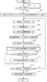
図4は、実施形態1に係る画像形成装置100が機種情報をBLE(Bluetooth Low Energy)のアドバタイジングパケットに書き込んで送信する処理を説明するフローチャートである。この処理を実行するプログラムはHDD308に格納されており、実行時に、CPU302によりRAM306に展開され、CPU302により実行されることにより、このフローチャートで示す処理が達成される。
FIG. 4 is a flowchart illustrating a process in which the
まずS401でCPU302は、ブルーツース通信部316が送信するBLEのアドバタイジングパケットに、この画像形成装置100の機種情報を書き込む。ここで機種情報は、例えば、機種毎に割り振られた機種番号等を含む。次にS402に進みCPU302は、S401で機種情報を書き込んだBLEのアドバタイジングパケットをブルーツース通信部316により送信させる。ここで、このアドバタイジングパケットには、他に、このアドバタイジングパケットの送信元のMACアドレス等が含まれる。
First, in S401, the
これにより、このアドバタイジングパケットを受信したモバイル端末110は、そのBLEのアドバタイジングパケットが、どの機種から発信されたものか識別できる。
As a result, the
図5は、実施形態1に係るモバイル端末110が、当該モバイル端末110と画像処理装置との間の距離を求めて所定距離内にある画像形成装置の一覧を表示する処理を説明するフローチャートである。このフローチャートで示す処理は、CPU202がROM204或いはHDD208からRAM206に展開したプログラムを実行することにより達成される。ここでモバイル端末110は、画像形成装置の機種情報と、モバイル端末110の機種情報とを基に、受信した電波強度の補正値を求めて電波強度を補正することにより、モバイル端末110と画像処理装置の距離を求めている。
FIG. 5 is a flowchart illustrating a process in which the
まずS501でCPU202は、図4のS402で発信されたアドバタイジングパケットを受信したかどうか判定し、アドバタイジングパケットを受信するとS502に進む。S502でCPU202は、ブルーツース通信部216が受信したアドバタイジングパケットと、その受信時の電波強度を、探索結果リストのキューに追加する。次にS503に進みCPU202は、S502でキューに追加されたアドバタイジングパケットと電波強度のキューから先頭のキューを取り出す。次にS504に進みCPU202は、S503でキューから取り出したアドバタイジングパケットに含まれる機種情報を解析し、その結果をRAM206に記憶する。次にS505に進みCPU202は、モバイル端末110自身の機種情報を取得してRAM206に記憶する。ここで、自身の機種情報とは、モバイル端末の機種を特定する情報であり、同機種のモバイル端末の機種情報は同じものとなる。
First, in S501, the
次にS506に進みCPU202は、S504で解析した画像形成装置の機種情報と、S505で解析したモバイル端末110の機種情報とを用いて電波強度補正値テーブルを参照し、適切な補正値を取得してRAM206に記憶する。次にS507に進みCPU202は、S506でRAM206に記憶した補正値を用いて、S503で取り出した電波強度を補正し、その補正した電波強度をRAM206に記憶する。
Next, the process proceeds to S506, and the
図6は、実施形態1に係るモバイル端末110が保持している電波強度補正値テーブルの一例を示す図である。この電波強度補正値テーブルは、例えばHDD208に記憶されている。
FIG. 6 is a diagram showing an example of a radio field intensity correction value table held by the
この電波強度補正値テーブルは、モバイル端末の機種と画像形成装置の機種との組み合わせに対応付けて、受信した電波の強度を補正する補正値を登録している。ここでモバイル端末Aは、実施形態1に係るモバイル端末110と同じとし、他のモバイル端末B、モバイル端末Cは、いずれも図示しないモバイル端末である。また画像形成装置Aは、実施形態1に係る画像形成装置100と同一とし、他の画像形成装置B、画像形成装置Cは、いずれも図示しない画像形成装置である。従って、モバイル端末110は、電波強度補正値テーブルとして、モバイル端末Aに対応する画像形成装置A〜Cの補正値だけを登録しても良い。この場合は、受信したパケットを送信した画像形成装置の機種情報に基づいて、受信した電波の強度を補正する補正値を取得することになる。ここで実施形態1に係るモバイル端末110と画像形成装置100との補正値は、図6の601で示すように「−8」となる。従って、この場合は、S507でCPU202は、S503で取り出した電波強度から8dBmを引くことにより、補正した電波強度を求める。
In this radio wave intensity correction value table, correction values for correcting the intensity of received radio waves are registered in association with the combination of the model of the mobile terminal and the model of the image forming apparatus. Here, the mobile terminal A is the same as the
次にS508に進みCPU202は、S507で求めた電波強度に基づいて、モバイル端末110と画像処理装置100との距離を取得してRAM206に記憶する。例えば、モバイル端末110と画像処理装置100との間で、S503で取り出した電波強度が−38dBmであったとする。モバイル端末110の画像処理装置100に対する補正値は、図6の電波強度補正テーブルより−8dBmであるため、補正後の電波強度は、−38dBm+(−8dBm)=−46dBmとなる。
Next, the process proceeds to S508, and the
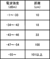
図7は、実施形態1における距離と電波強度の標準的な関係を示す図である。 FIG. 7 is a diagram showing a standard relationship between the distance and the radio wave intensity in the first embodiment.
ここでは電波強度の範囲に対応付けて、モバイル端末と画像形成装置との距離(cm)が記憶されている。 Here, the distance (cm) between the mobile terminal and the image forming apparatus is stored in association with the range of radio wave intensity.
前述の例のように、S508で算出した補正後の電波強度が−46dBmの場合、図7から、モバイル端末110と画像形成装置100との間の距離は、33cmであることがわかる。
As in the above example, when the corrected radio wave intensity calculated in S508 is −46 dBm, it can be seen from FIG. 7 that the distance between the
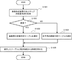
次にS509に進みCPU202は、S508でRAM206に記憶したモバイル端末110と画像形成装置間との間の距離が所定値以下であるか否かを判定する。ここで距離が所定値以下の場合はS510へ進み、そうでない場合はS511へ進む。実施形態1では、この所定値を、例えば0.33m(33cm)とする。S510でCPU202は、S503で取り出したアドバタイジングパケットを発信した画像形成装置を、画像形成装置の探索結果リストに追加してS511に処理を進める。S511でCPU202は、S502で探索結果リストに追加された全てのキューに対して処理が完了したかどうかを判定し、全てのキューに対する処理が完了したと判定するとS512へ進み、そうでない場合はS503へ進む。S512でCPU202は、S510で作成した画像形成装置の探索結果リストに基づいて、所定の距離内にある画像形成装置の一覧画面を操作部212へ表示して、この処理を終了する。
Next, the process proceeds to S509, and the
図8は、実施形態1に係るモバイル端末110の操作部212に表示される画像形成装置の一覧画面の一例を示す図である。図8は、画像形成装置Aと画像形成装置Cが、モバイル端末110から0.33m以内にあるときの画像形成装置の一覧画面である。
FIG. 8 is a diagram showing an example of a list screen of the image forming apparatus displayed on the
このように実施形態1によれば、モバイル端末と、モバイル端末が受信したアドバタイジングパケットを発信した画像形成装置の組み合わせから電波強度の補正値を求めている。そして、その補正値を使用してモバイル端末が受信した電波強度を補正し、その補正した電波強度に基づいて画像形成装置との間の距離を求めることにより、より正確にモバイル端末と画像形成装置との間の距離を検出することができる。 As described above, according to the first embodiment, the correction value of the radio wave intensity is obtained from the combination of the mobile terminal and the image forming apparatus that transmits the advertising packet received by the mobile terminal. Then, the correction value is used to correct the radio wave intensity received by the mobile terminal, and the distance between the mobile terminal and the image forming device is obtained based on the corrected radio wave intensity, so that the mobile terminal and the image forming device are more accurately used. The distance between and can be detected.
[実施形態2]
次に本発明の実施形態2を説明する。実施形態2では、モバイル端末110は、相手の画像形成装置のBLEチップの設置向きに応じて電波強度の補正値を求める例で説明する。尚、実施形態2に係る画像形成装置100及びモバイル端末110の構成は、前述の実施形態1と同様であるため、その説明を省略する。
[Embodiment 2]
Next, Embodiment 2 of the present invention will be described. In the second embodiment, the
図9は、実施形態2に係るモバイル端末110が保持している電波強度補正値テーブルの一例を示す図である。この電波強度補正値テーブルは、例えばHDD208に記憶されている。
FIG. 9 is a diagram showing an example of a radio field intensity correction value table held by the
図9(A)は、各画像形成装置のBLEチップの設置向きが、画像形成装置の地面に対して垂直方向か水平方向かを示している。例えば、画像形成装置AとCは垂直であり、画像形成装置Bは水平である。 FIG. 9A shows whether the installation direction of the BLE chip of each image forming apparatus is vertical or horizontal with respect to the ground of the image forming apparatus. For example, the image forming devices A and C are vertical, and the image forming device B is horizontal.
図10は、画像形成装置のBLEチップの設置向きを説明する図である。 FIG. 10 is a diagram illustrating an installation orientation of the BLE chip of the image forming apparatus.
ここでBLEチップの設置向きが垂直とは、1001で示すように画像形成装置の側面にBLEチップが取り付けられている状態である。またチップ設置向きが水平とは、1002で示すように、画像形成装置の上面にBLEチップが取り付けられている状態である。電波を発信するBLEチップの設置向きが垂直か、水平かによって、電波が発信される方向が変わり、モバイル端末110の受信感度に影響があると考えられる。
Here, the vertical installation direction of the BLE chip means that the BLE chip is attached to the side surface of the image forming apparatus as shown by 1001. Further, when the chip installation direction is horizontal, as shown by 1002, the BLE chip is attached to the upper surface of the image forming apparatus. Depending on whether the BLE chip that transmits radio waves is installed vertically or horizontally, the direction in which radio waves are transmitted changes, which is considered to affect the reception sensitivity of the
図9(B)は、各モバイル端末における、画像形成装置のBLEチップの設置向きに対応する補正値を示している。 FIG. 9B shows correction values corresponding to the installation orientation of the BLE chip of the image forming apparatus in each mobile terminal.
例えば、モバイル端末Bは、BLEチップの設置向きが水平である画像形成装置に対しては、−8dBmの補正値を選択する。このように、画像形成装置をBLEチップの設置向きが垂直か、水平かに分類する。そして画像形成装置100から受信した機種情報に基づいて、画像形成装置のBLEチップの設置向きを決定し、それに基づいてモバイル端末110の画像形成装置100に対する電波強度の補正値を決定する。尚、実施形態2では、BLEチップの設置向きが垂直であるか水平であるかに分類したが、例えば、BLEチップの設置場所や、BLEチップの種類で分類して補正値を決定しても良い。
For example, the mobile terminal B selects a correction value of −8 dBm for an image forming apparatus in which the installation direction of the BLE chip is horizontal. In this way, the image forming apparatus is classified according to whether the installation direction of the BLE chip is vertical or horizontal. Then, based on the model information received from the
図11は、実施形態2に係るモバイル端末110による図5のS506の処理を説明するフローチャートである。モバイル端末110が画像処理装置100との間の距離を求めて所定距離内にある画像形成装置の一覧を表示するその他の工程は、図5で示す処理と同じである。このフローチャートで示す処理は、CPU202がROM204或いはHDD208からRAM206に展開したプログラムを実行することにより達成される。
FIG. 11 is a flowchart illustrating the process of S506 in FIG. 5 by the
S1101でCPU202は、S504で取得した画像形成装置の機種情報に基づいて、図9(A)のテーブルを参照して画像形成装置におけるBLEチップの設置向きを取得する。そしてS1102に進みCPU202は、BLEチップの設置向きが垂直かどうか判定し、垂直である判定するとS1103に進み、例えば図9(B)の垂直用の補正値を取得する。ここでは例えば、モバイル端末Aであれば、補正値として−8dBmを取得してS507に進む。一方、S1102でCPU202は、BLEチップの設置向きが水平であると判定するとS1104に進み、例えば図9(B)の水平用の補正値を取得する。ここでは例えば、モバイル端末Aであれば、補正値として−11dBmを取得してS507に進む。そしてS507でCPU202は、S1103或いはS1104で取得した補正値に基づいて、S503で読み出した電波強度を補正する。
In S1101, the
以上説明したように実施形態2によれば、画像形成装置におけるBLEチップの設置向きが垂直か、水平かに応じて、電波強度を補正する補正値を求めて電波強度を補正する。これにより、電波を発信するBLEチップの設置向きが垂直か水平かによって電波が発信される方向が変わり、モバイル端末の受信感度に影響がある場合にも対処できるという効果がある。 As described above, according to the second embodiment, the radio wave intensity is corrected by obtaining a correction value for correcting the radio wave intensity according to whether the installation direction of the BLE chip in the image forming apparatus is vertical or horizontal. As a result, the direction in which radio waves are transmitted changes depending on whether the installation direction of the BLE chip that transmits radio waves is vertical or horizontal, which has the effect of being able to deal with cases where the reception sensitivity of the mobile terminal is affected.
[実施形態3]
次に本発明の実施形態3を説明する。実施形態3では、モバイル端末110は、相手の画像形成装置の機種と、自端末の機種とに応じた距離判定テーブルを有しており、そのテーブルと電波強度とに基づいて距離を求める例で説明する。尚、実施形態3に係る画像形成装置100及びモバイル端末110の構成は、前述の実施形態1と同様であるため、その説明を省略する。
[Embodiment 3]
Next,
図12は、実施形態3に係るモバイル端末110が、当該モバイル端末110と画像処理装置との間の距離を求めて所定距離内にある画像形成装置の一覧を表示する処理を説明するフローチャートである。このフローチャートで示す処理は、CPU202がROM204或いはHDD208からRAM206に展開したプログラムを実行することにより達成される。尚、図12において、S1201〜S1205、及びS1208〜S1211の処理は、前述の実施形態1に係る図5のS501〜S505、S509〜S512の処理と同じであるため、それらの説明を省略する。
FIG. 12 is a flowchart illustrating a process in which the
S1206でCPU202は、S2104で解析して取得した画像形成装置100の機種情報と、S1205で取得したモバイル端末110の機種情報とを用いて、適切な距離判定テーブルを取得してRAM206に記憶する。
In S1206, the
図13は、実施形態3に係る距離判定テーブルの一例を説明する図である。 FIG. 13 is a diagram illustrating an example of a distance determination table according to the third embodiment.
図13(A)は、モバイル端末と画像形成装置との組合わせに応じて、どの距離判定テーブルを参照するかを規定するテーブル例を示している。図13(B)〜図13(F)は、第1〜第5距離判定テーブルの一例を説明する図である。 FIG. 13A shows an example of a table that defines which distance determination table is referred to according to the combination of the mobile terminal and the image forming apparatus. 13 (B) to 13 (F) are diagrams for explaining an example of the first to fifth distance determination tables.
ここで、例えばモバイル端末Aはモバイル端末110と同一し、画像形成装置Aは画像形成装置100に対応している。この場合は図13(A)より、第1距離判定テーブル(図13(B)が選択される。
Here, for example, the mobile terminal A is the same as the
こうしてS1206でCPU202は、S1203でキューから取り出した電波強度とS1206でRAM206に記憶した距離判定テーブルから、モバイル端末110と画像形成装置100の距離を特定する。上述の例では、S1206で第1距離判定テーブルが選択される。その場合、受信した電波強度が、例えば−38dBmであれば、図13(B)より、モバイル端末110と画像形成装置100の距離は10cmと決定される。
In this way, the
以上説明したように実施形態3によれば、モバイル端末と画像形成装置の機種情報、及びモバイル端末が受信した電波強度から、モバイル端末と画像形成装置との距離を求めることができる。 As described above, according to the third embodiment, the distance between the mobile terminal and the image forming apparatus can be obtained from the model information of the mobile terminal and the image forming apparatus and the radio wave intensity received by the mobile terminal.
[実施形態4]
次に本発明の実施形態4を説明する。実施形態4では、モバイル端末110は、相手の画像形成装置のBLEチップの設置向きと、自端末の機種とに応じて距離判定テーブルを選択し、その選択したテーブルと電波強度とに基づいて距離を求める例で説明する。尚、実施形態4に係る画像形成装置100及びモバイル端末110の構成は、前述の実施形態1と同様であるため、その説明を省略する。
[Embodiment 4]
Next, Embodiment 4 of the present invention will be described. In the fourth embodiment, the
図14は、実施形態4において図12のS1206で参照するテーブルの一例を示す図である。 FIG. 14 is a diagram showing an example of the table referred to in S1206 of FIG. 12 in the fourth embodiment.
ここではモバイル端末の機種と、画像形成装置のBLEチップの設置向きが垂直、水平の場合に対応して選択する距離判定テーブルを特定している。例えば、モバイル端末Bの場合は、BLEチップの設置向きが水平の画像形成装置に対して第1距離判定テーブルを選択し、BLEチップの設置向きが垂直の画像形成装置に対して第2距離判定テーブルを選択する。このように、画像形成装置100の機種情報に基づいて、その画像形成装置のBLEチップの設置向きが垂直か、水平かを判定し、モバイル端末110の機種に対応する距離判定テーブルを決定する。尚、この実施形態4では、画像形成装置のBLEチップの設置向きが垂直か、水平かで分類したが、例えば、BLEチップの設置場所や、BLEチップの種類に応じて、距離判定テーブルを決定しても良い。
Here, the model of the mobile terminal and the distance determination table to be selected corresponding to the case where the installation direction of the BLE chip of the image forming apparatus is vertical or horizontal are specified. For example, in the case of the mobile terminal B, the first distance determination table is selected for the image forming device in which the BLE chip is installed in the horizontal direction, and the second distance determination is made for the image forming device in which the BLE chip is installed in the vertical direction. Select a table. In this way, based on the model information of the
図15は、実施形態4に係るモバイル端末110による図5のS506〜S508に代わる処理を説明するフローチャートである。モバイル端末110が画像処理装置100との間の距離を求めて所定距離内にある画像形成装置の一覧を表示するその他のステップは、図5で示す処理と同じである。このフローチャートで示す処理は、CPU202がROM204或いはHDD208からRAM206に展開したプログラムを実行することにより達成される。
FIG. 15 is a flowchart illustrating a process alternative to S506 to S508 of FIG. 5 by the
S505でCPU202は、自身のモバイル端末110の機種情報を取得するとS1501に進む。S1501でCPU202は、S504で解析して取得した画像形成装置の機種情報に基づいて、その画像形成装置のBLEチップの設置向きを取得する。ここでは例えば前述の図9(A)に示すようなテーブルを参照して、画像形成装置のBLEチップの設置向きを取得する。次にS1502に進みCPU202は、その画像形成装置のBLEチップの設置向きが垂直かどうか判定する。垂直と判定するとS1503に進みCPU202は、図14のテーブルで、モバイル端末110の機種と、BLEチップの設置向きが垂直とから、対応する距離判定テーブルを選択してS1505に進む。一方、S1502で水平と判定するとS1504に進みCPU202は、図14のテーブルで、モバイル端末110の機種とBLEチップの設置向きが水平とから、対応する距離判定テーブルを選択してS1505に進む。S1505でCPU202は、S1503或いはS1504で選択した距離判定テーブルと、S503で読み出した電波強度とに基づいてモバイル端末110と画像形成装置との距離を求めてS509に進む。
When the
以上説明したように実施形態4によれば、画像形成装置におけるBLEチップの設置向きが垂直か、水平かに応じて、電波強度に対応するモバイル端末と画像形成装置との距離を求めることができる。これにより、電波を発信するBLEチップの設置向きが垂直か水平かによって電波が発信される方向が変わり、モバイル端末の受信感度に影響がある場合にも対処できるという効果がある。 As described above, according to the fourth embodiment, the distance between the mobile terminal corresponding to the radio wave intensity and the image forming apparatus can be obtained according to whether the installation direction of the BLE chip in the image forming apparatus is vertical or horizontal. .. As a result, the direction in which radio waves are transmitted changes depending on whether the installation direction of the BLE chip that transmits radio waves is vertical or horizontal, which has the effect of being able to deal with cases where the reception sensitivity of the mobile terminal is affected.
(その他の実施形態)
本発明は、上述の実施形態の1以上の機能を実現するプログラムを、ネットワーク又は記憶媒体を介してシステム又は装置に供給し、そのシステム又は装置のコンピュータにおける1つ以上のプロセッサーがプログラムを読出し実行する処理でも実現可能である。また、1以上の機能を実現する回路(例えば、ASIC)によっても実現可能である。
(Other embodiments)
The present invention supplies a program that realizes one or more functions of the above-described embodiment to a system or device via a network or storage medium, and one or more processors in the computer of the system or device reads and executes the program. It can also be realized by the processing to be performed. It can also be realized by a circuit (for example, ASIC) that realizes one or more functions.
本発明は上記実施形態に制限されるものではなく、本発明の精神及び範囲から離脱することなく、様々な変更及び変形が可能である。従って、本発明の範囲を公にするために、以下の請求項を添付する。 The present invention is not limited to the above embodiments, and various modifications and modifications can be made without departing from the spirit and scope of the present invention. Therefore, in order to make the scope of the present invention public, the following claims are attached.
100…画像形成装置、110…モバイル端末、202…CPU、204…ROM、206…RAM、208…HDD,212…操作部 100 ... image forming device, 110 ... mobile terminal, 202 ... CPU, 204 ... ROM, 206 ... RAM, 208 ... HDD, 212 ... operation unit
Claims (10)
一以上の外部装置の識別情報と各々の前記外部装置のパケットの送信部の設置向きを示す情報とを対応付けて第一の情報として保存し、かつ、前記設置向きを示す情報と補正値とを対応付けて第二の情報として保存する保存手段と、
外部装置から送信されたパケットを受信する受信手段と、
前記受信手段で受信した前記パケットに含まれる前記外部装置の識別情報と前記保存手段に保存されている前記第一の情報と前記第二の情報とに基づいて補正値を決定する決定手段と、
前記決定手段で決定された前記補正値と、前記受信手段で受信した前記パケットの電波強度とを用いて所定の処理を実行する実行手段と、
を有することを特徴とする通信装置。 A communication device that performs wireless communication
The identification information of one or more external devices and the information indicating the installation direction of the packet transmission unit of each of the external devices are associated and stored as the first information, and the information indicating the installation direction and the correction value are used. And a storage means that stores as second information in association with
A receiving means for receiving packets transmitted from an external device,
A determining means for determining a correction value based on the identification information of the external device included in the packet received by the receiving means, the first information stored in the storage means, and the second information.
An execution means that executes a predetermined process using the correction value determined by the determination means and the radio wave intensity of the packet received by the reception means.
A communication device characterized by having.
1以上の外部装置の識別情報と自装置を含む複数の通信装置の識別情報とに対応付けて、複数の補正値を保存する保存手段と、
外部装置から送信されたパケットを受信する受信手段と、
前記自装置の識別情報と、前記受信手段で受信した前記パケットに含まれる前記外部装置の識別情報とに基づいて、前記保存手段で保存された前記複数の補正値の中から補正値を決定する決定手段と、
前記決定手段で決定した補正値と、前記受信手段で受信した前記パケットの電波強度とを用いて所定の処理を実行する実行手段と、
を有することを特徴とする通信装置。 A communication device that performs wireless communication
A storage means for storing a plurality of correction values in association with the identification information of one or more external devices and the identification information of a plurality of communication devices including the own device .
A receiving means for receiving packets transmitted from an external device,
Based on the identification information of the own device and the identification information of the external device included in the packet received by the receiving means, the correction value is determined from the plurality of correction values stored by the storage means. Determining means and
An execution means that executes a predetermined process using the correction value determined by the determination means and the radio wave intensity of the packet received by the reception means.
A communication device characterized by having.
前記通信装置の保存手段が、一以上の外部装置の識別情報と各々の前記外部装置のパケットの送信部の設置向きを示す情報とを対応付けて第一の情報として保存し、かつ、前記設置向きを示す情報と補正値とを対応付けて第二の情報として保存する保存工程と、
前記通信装置の受信手段が、外部装置から送信されたパケットを受信する受信工程と、
前記通信装置の決定手段が、前記受信工程で受信した前記パケットに含まれる前記外部装置の識別情報と、前記保存工程で保存された前記第一の情報と前記第二の情報とに基づいて補正値を決定する決定工程と、
前記通信装置の実行手段が、前記決定工程で決定された補正値と、前記受信工程で受信した前記パケットの電波強度とを用いて所定の処理を実行する実行工程と、
を有することを特徴とする通信装置の制御方法。 It is a control method that controls a communication device that performs wireless communication.
The storage means of the communication device stores the identification information of one or more external devices and the information indicating the installation direction of the packet transmission unit of each external device as the first information, and stores the information. A storage process in which the information indicating the orientation is associated with the correction value and stored as the second information,
A receiving step in which the receiving means of the communication device receives a packet transmitted from the external device,
The determining means of the communication device corrects based on the identification information of the external device included in the packet received in the receiving step, the first information saved in the saving step, and the second information. The decision process to determine the value and
An execution step in which the execution means of the communication device executes a predetermined process using the correction value determined in the determination step and the radio wave intensity of the packet received in the reception step.
A method for controlling a communication device, which comprises.
Priority Applications (3)
| Application Number | Priority Date | Filing Date | Title |
|---|---|---|---|
| JP2016060902A JP6789649B2 (en) | 2016-03-24 | 2016-03-24 | Communication devices, their control methods, and programs |
| US15/460,625 US10338860B2 (en) | 2016-03-24 | 2017-03-16 | Communication apparatus that corrects the radio field intensity of a received packet, and method of controlling the same |
| US16/408,652 US10802773B2 (en) | 2016-03-24 | 2019-05-10 | Communication apparatus that determines a correction value based on information in a received packet corresponding to a transmitting apparatus and method of controlling the same |
Applications Claiming Priority (1)
| Application Number | Priority Date | Filing Date | Title |
|---|---|---|---|
| JP2016060902A JP6789649B2 (en) | 2016-03-24 | 2016-03-24 | Communication devices, their control methods, and programs |
Publications (3)
| Publication Number | Publication Date |
|---|---|
| JP2017175467A JP2017175467A (en) | 2017-09-28 |
| JP2017175467A5 JP2017175467A5 (en) | 2019-05-09 |
| JP6789649B2 true JP6789649B2 (en) | 2020-11-25 |
Family
ID=59897202
Family Applications (1)
| Application Number | Title | Priority Date | Filing Date |
|---|---|---|---|
| JP2016060902A Active JP6789649B2 (en) | 2016-03-24 | 2016-03-24 | Communication devices, their control methods, and programs |
Country Status (2)
| Country | Link |
|---|---|
| US (2) | US10338860B2 (en) |
| JP (1) | JP6789649B2 (en) |
Families Citing this family (4)
| Publication number | Priority date | Publication date | Assignee | Title |
|---|---|---|---|---|
| JP7042623B2 (en) * | 2018-01-05 | 2022-03-28 | キヤノン株式会社 | Information processing equipment, information processing system and storage medium |
| JP7013938B2 (en) * | 2018-02-27 | 2022-02-01 | セイコーエプソン株式会社 | Terminal equipment, communication system, program and display control method |
| JP7024556B2 (en) * | 2018-03-30 | 2022-02-24 | 株式会社リコー | Information processing systems, information processing methods and programs |
| JP7464028B2 (en) | 2021-09-16 | 2024-04-09 | トヨタ自動車株式会社 | Information processing device, vehicle, information processing method, and computer program |
Family Cites Families (12)
| Publication number | Priority date | Publication date | Assignee | Title |
|---|---|---|---|---|
| US7406323B2 (en) * | 2001-11-01 | 2008-07-29 | Sony Corporation | Communication system and method, information processing terminal and method, and information processing apparatus and method |
| JP4779127B2 (en) * | 2007-11-15 | 2011-09-28 | ソニー株式会社 | Wireless communication apparatus, program, and wireless communication method |
| JP2009276866A (en) * | 2008-05-13 | 2009-11-26 | Ricoh Co Ltd | Information processor, image forming apparatus, information processing system, method for controlling information processor, program, and recording medium |
| JP5817196B2 (en) * | 2010-09-29 | 2015-11-18 | ブラザー工業株式会社 | Portable device program and portable device control method |
| JP5849918B2 (en) * | 2012-09-28 | 2016-02-03 | 株式会社デンソー | Vehicle communication device |
| JP6390141B2 (en) * | 2014-04-07 | 2018-09-19 | スター精密株式会社 | Information processing apparatus control system using portable terminal, portable terminal, information processing apparatus control method, and control program |
| JP2015216483A (en) * | 2014-05-09 | 2015-12-03 | キヤノン株式会社 | Terminal device, control method therefor and program |
| JP6044598B2 (en) * | 2014-07-02 | 2016-12-14 | コニカミノルタ株式会社 | Image processing system, image processing apparatus, and program |
| JP2016017793A (en) * | 2014-07-07 | 2016-02-01 | 日本電気株式会社 | Wireless positioning device, wireless positioning method, wireless positioning system, and computer program |
| JP6176229B2 (en) * | 2014-12-15 | 2017-08-09 | コニカミノルタ株式会社 | Mobile terminal and program |
| US9729736B2 (en) * | 2015-02-26 | 2017-08-08 | Ricoh Company, Ltd. | Information processing apparatus, storage medium, and information processing system |
| JP6265192B2 (en) * | 2015-09-25 | 2018-01-24 | コニカミノルタ株式会社 | COMMUNICATION DEVICE, COMMUNICATION SYSTEM, AND APPLICATION PROGRAM |
-
2016
- 2016-03-24 JP JP2016060902A patent/JP6789649B2/en active Active
-
2017
- 2017-03-16 US US15/460,625 patent/US10338860B2/en not_active Expired - Fee Related
-
2019
- 2019-05-10 US US16/408,652 patent/US10802773B2/en active Active
Also Published As
| Publication number | Publication date |
|---|---|
| US10338860B2 (en) | 2019-07-02 |
| JP2017175467A (en) | 2017-09-28 |
| US20190265916A1 (en) | 2019-08-29 |
| US20170277479A1 (en) | 2017-09-28 |
| US10802773B2 (en) | 2020-10-13 |
Similar Documents
| Publication | Publication Date | Title |
|---|---|---|
| JP6789649B2 (en) | Communication devices, their control methods, and programs | |
| US20180132167A1 (en) | Wireless network access method and apparatus | |
| EP3197076B1 (en) | Information processing apparatus and method of deciding correction amount in the information processing apparatus | |
| JP6625383B2 (en) | Computer readable program, audio controller, and wireless audio system | |
| US20140098249A1 (en) | Terminal, method of forming video, apparatus to form an image, driving method thereof, and computer-readable recording medium | |
| JP2014179798A5 (en) | Printing apparatus, control method therefor, and program | |
| EP2584454A2 (en) | Mobile apparatus and print controlling method | |
| US20190011269A1 (en) | Position estimation device, position estimation method, and recording medium | |
| US9292231B2 (en) | Image forming apparatus, image forming system, and recording medium | |
| US9374499B2 (en) | Information processing apparatus, method for controlling information processing apparatus, and storage medium | |
| JP6898772B2 (en) | Communication terminals, their control methods, and programs | |
| JP5956035B1 (en) | Waiting time estimation system and waiting time estimation method | |
| JP2015153116A (en) | communication device | |
| US20210396543A1 (en) | Information processing apparatus, information processing method, and program | |
| JP4899194B2 (en) | Terminal, network device, network device search system including terminal and network device, and network device search method | |
| US20150286450A1 (en) | Communication apparatus, control method therefor, and computer-readable storage medium | |
| US20190012767A1 (en) | Terminal device, display system, and control method of terminal device | |
| JP6813380B2 (en) | Equipment management system, equipment management device, equipment management method, and program | |
| US20210044706A1 (en) | Information processing apparatus, storage medium, and control method | |
| JP2015152565A (en) | Electronic apparatus | |
| CN105628018A (en) | Information acquisition method and electronic equipment | |
| US10009488B1 (en) | Methods and systems for automatically initiating print device service requests using proactive incident detection and analysis | |
| JP2021103426A (en) | Image processing system, image processing method, and program | |
| AU2016219541B2 (en) | Terminal device, diagnosis system, diagnosis method, and program | |
| US20190090217A1 (en) | Location setting method |
Legal Events
| Date | Code | Title | Description |
|---|---|---|---|
| A521 | Request for written amendment filed |
Free format text: JAPANESE INTERMEDIATE CODE: A523 Effective date: 20190319 |
|
| A621 | Written request for application examination |
Free format text: JAPANESE INTERMEDIATE CODE: A621 Effective date: 20190319 |
|
| A977 | Report on retrieval |
Free format text: JAPANESE INTERMEDIATE CODE: A971007 Effective date: 20200129 |
|
| A131 | Notification of reasons for refusal |
Free format text: JAPANESE INTERMEDIATE CODE: A131 Effective date: 20200207 |
|
| A521 | Request for written amendment filed |
Free format text: JAPANESE INTERMEDIATE CODE: A523 Effective date: 20200403 |
|
| A131 | Notification of reasons for refusal |
Free format text: JAPANESE INTERMEDIATE CODE: A131 Effective date: 20200605 |
|
| A521 | Request for written amendment filed |
Free format text: JAPANESE INTERMEDIATE CODE: A523 Effective date: 20200728 |
|
| TRDD | Decision of grant or rejection written | ||
| A01 | Written decision to grant a patent or to grant a registration (utility model) |
Free format text: JAPANESE INTERMEDIATE CODE: A01 Effective date: 20201005 |
|
| A61 | First payment of annual fees (during grant procedure) |
Free format text: JAPANESE INTERMEDIATE CODE: A61 Effective date: 20201104 |
|
| R151 | Written notification of patent or utility model registration |
Ref document number: 6789649 Country of ref document: JP Free format text: JAPANESE INTERMEDIATE CODE: R151 |