JP6781989B2 - Fine particle detection system and fine particle detection program - Google Patents
Fine particle detection system and fine particle detection program Download PDFInfo
- Publication number
- JP6781989B2 JP6781989B2 JP2017514177A JP2017514177A JP6781989B2 JP 6781989 B2 JP6781989 B2 JP 6781989B2 JP 2017514177 A JP2017514177 A JP 2017514177A JP 2017514177 A JP2017514177 A JP 2017514177A JP 6781989 B2 JP6781989 B2 JP 6781989B2
- Authority
- JP
- Japan
- Prior art keywords
- fine particles
- unit
- zeta potential
- particle
- flow path
- Prior art date
- Legal status (The legal status is an assumption and is not a legal conclusion. Google has not performed a legal analysis and makes no representation as to the accuracy of the status listed.)
- Active
Links
- 239000010419 fine particle Substances 0.000 title claims description 266
- 238000001514 detection method Methods 0.000 title claims description 110
- 239000002245 particle Substances 0.000 claims description 293
- 210000001808 exosome Anatomy 0.000 claims description 153
- 238000005286 illumination Methods 0.000 claims description 122
- 238000011156 evaluation Methods 0.000 claims description 67
- 239000012530 fluid Substances 0.000 claims description 51
- 210000002472 endoplasmic reticulum Anatomy 0.000 claims description 39
- 238000003860 storage Methods 0.000 claims description 37
- 239000000126 substance Substances 0.000 claims description 36
- 230000003287 optical effect Effects 0.000 claims description 34
- 238000004364 calculation method Methods 0.000 claims description 31
- 230000009870 specific binding Effects 0.000 claims description 23
- 238000009434 installation Methods 0.000 claims description 20
- 238000009826 distribution Methods 0.000 claims description 17
- 230000008859 change Effects 0.000 claims description 16
- 238000003384 imaging method Methods 0.000 claims description 12
- 230000005653 Brownian motion process Effects 0.000 claims description 4
- 238000005537 brownian motion Methods 0.000 claims description 4
- 230000001678 irradiating effect Effects 0.000 claims description 4
- 238000006243 chemical reaction Methods 0.000 claims description 2
- 238000004458 analytical method Methods 0.000 description 23
- 238000001962 electrophoresis Methods 0.000 description 18
- 230000009471 action Effects 0.000 description 17
- 238000010586 diagram Methods 0.000 description 16
- 239000000463 material Substances 0.000 description 16
- 210000004027 cell Anatomy 0.000 description 15
- 238000000034 method Methods 0.000 description 15
- 230000005012 migration Effects 0.000 description 12
- 238000013508 migration Methods 0.000 description 12
- 239000000523 sample Substances 0.000 description 12
- 239000012488 sample solution Substances 0.000 description 12
- 230000027455 binding Effects 0.000 description 10
- 230000004907 flux Effects 0.000 description 10
- 230000033001 locomotion Effects 0.000 description 9
- 230000008569 process Effects 0.000 description 9
- 230000000704 physical effect Effects 0.000 description 8
- 108090000623 proteins and genes Proteins 0.000 description 8
- 201000010099 disease Diseases 0.000 description 7
- 208000037265 diseases, disorders, signs and symptoms Diseases 0.000 description 7
- 238000002372 labelling Methods 0.000 description 7
- 102000004169 proteins and genes Human genes 0.000 description 7
- 230000004520 agglutination Effects 0.000 description 6
- 230000005684 electric field Effects 0.000 description 6
- 230000006870 function Effects 0.000 description 6
- 108091023037 Aptamer Proteins 0.000 description 5
- 230000002776 aggregation Effects 0.000 description 5
- 238000004220 aggregation Methods 0.000 description 5
- 230000005540 biological transmission Effects 0.000 description 5
- 239000007853 buffer solution Substances 0.000 description 5
- 230000007423 decrease Effects 0.000 description 5
- 230000007246 mechanism Effects 0.000 description 5
- XEEYBQQBJWHFJM-UHFFFAOYSA-N Iron Chemical compound [Fe] XEEYBQQBJWHFJM-UHFFFAOYSA-N 0.000 description 4
- 239000000427 antigen Substances 0.000 description 4
- 108091007433 antigens Proteins 0.000 description 4
- 102000036639 antigens Human genes 0.000 description 4
- 210000004369 blood Anatomy 0.000 description 4
- 239000008280 blood Substances 0.000 description 4
- 230000003247 decreasing effect Effects 0.000 description 4
- 239000003446 ligand Substances 0.000 description 4
- 229910052751 metal Inorganic materials 0.000 description 4
- 239000002184 metal Substances 0.000 description 4
- 230000036961 partial effect Effects 0.000 description 4
- 238000003825 pressing Methods 0.000 description 4
- 238000012545 processing Methods 0.000 description 4
- VYPSYNLAJGMNEJ-UHFFFAOYSA-N Silicium dioxide Chemical compound O=[Si]=O VYPSYNLAJGMNEJ-UHFFFAOYSA-N 0.000 description 3
- 230000005856 abnormality Effects 0.000 description 3
- 230000002411 adverse Effects 0.000 description 3
- 238000005516 engineering process Methods 0.000 description 3
- 239000000284 extract Substances 0.000 description 3
- 150000002632 lipids Chemical class 0.000 description 3
- 239000007788 liquid Substances 0.000 description 3
- 238000005259 measurement Methods 0.000 description 3
- 239000012528 membrane Substances 0.000 description 3
- 108090000765 processed proteins & peptides Proteins 0.000 description 3
- 239000000243 solution Substances 0.000 description 3
- 229920001059 synthetic polymer Polymers 0.000 description 3
- 210000002700 urine Anatomy 0.000 description 3
- YBJHBAHKTGYVGT-ZKWXMUAHSA-N (+)-Biotin Chemical compound N1C(=O)N[C@@H]2[C@H](CCCCC(=O)O)SC[C@@H]21 YBJHBAHKTGYVGT-ZKWXMUAHSA-N 0.000 description 2
- 241000894006 Bacteria Species 0.000 description 2
- 102100027221 CD81 antigen Human genes 0.000 description 2
- 102100037904 CD9 antigen Human genes 0.000 description 2
- 101000914479 Homo sapiens CD81 antigen Proteins 0.000 description 2
- UQSXHKLRYXJYBZ-UHFFFAOYSA-N Iron oxide Chemical compound [Fe]=O UQSXHKLRYXJYBZ-UHFFFAOYSA-N 0.000 description 2
- 206010028980 Neoplasm Diseases 0.000 description 2
- PXHVJJICTQNCMI-UHFFFAOYSA-N Nickel Chemical compound [Ni] PXHVJJICTQNCMI-UHFFFAOYSA-N 0.000 description 2
- 108010079855 Peptide Aptamers Proteins 0.000 description 2
- 108700031126 Tetraspanins Proteins 0.000 description 2
- 102000043977 Tetraspanins Human genes 0.000 description 2
- 241000700605 Viruses Species 0.000 description 2
- 230000001640 apoptogenic effect Effects 0.000 description 2
- 239000011324 bead Substances 0.000 description 2
- 201000011510 cancer Diseases 0.000 description 2
- 210000000170 cell membrane Anatomy 0.000 description 2
- 238000004891 communication Methods 0.000 description 2
- 239000000470 constituent Substances 0.000 description 2
- 238000003745 diagnosis Methods 0.000 description 2
- 239000004205 dimethyl polysiloxane Substances 0.000 description 2
- LOKCTEFSRHRXRJ-UHFFFAOYSA-I dipotassium trisodium dihydrogen phosphate hydrogen phosphate dichloride Chemical compound P(=O)(O)(O)[O-].[K+].P(=O)(O)([O-])[O-].[Na+].[Na+].[Cl-].[K+].[Cl-].[Na+] LOKCTEFSRHRXRJ-UHFFFAOYSA-I 0.000 description 2
- 238000012377 drug delivery Methods 0.000 description 2
- 230000008030 elimination Effects 0.000 description 2
- 238000003379 elimination reaction Methods 0.000 description 2
- RWSXRVCMGQZWBV-WDSKDSINSA-N glutathione Chemical compound OC(=O)[C@@H](N)CCC(=O)N[C@@H](CS)C(=O)NCC(O)=O RWSXRVCMGQZWBV-WDSKDSINSA-N 0.000 description 2
- 229910052742 iron Inorganic materials 0.000 description 2
- 238000004519 manufacturing process Methods 0.000 description 2
- 150000002739 metals Chemical class 0.000 description 2
- 239000000693 micelle Substances 0.000 description 2
- 108091008104 nucleic acid aptamers Proteins 0.000 description 2
- 239000002953 phosphate buffered saline Substances 0.000 description 2
- BASFCYQUMIYNBI-UHFFFAOYSA-N platinum Chemical compound [Pt] BASFCYQUMIYNBI-UHFFFAOYSA-N 0.000 description 2
- 229920000435 poly(dimethylsiloxane) Polymers 0.000 description 2
- 229920000642 polymer Polymers 0.000 description 2
- 108020003175 receptors Proteins 0.000 description 2
- 102000005962 receptors Human genes 0.000 description 2
- 230000002829 reductive effect Effects 0.000 description 2
- 210000003296 saliva Anatomy 0.000 description 2
- 230000003248 secreting effect Effects 0.000 description 2
- 230000028327 secretion Effects 0.000 description 2
- 239000000725 suspension Substances 0.000 description 2
- 108090001008 Avidin Proteins 0.000 description 1
- 102100025222 CD63 antigen Human genes 0.000 description 1
- OKTJSMMVPCPJKN-UHFFFAOYSA-N Carbon Chemical compound [C] OKTJSMMVPCPJKN-UHFFFAOYSA-N 0.000 description 1
- 108091006027 G proteins Proteins 0.000 description 1
- 102000030782 GTP binding Human genes 0.000 description 1
- 108091000058 GTP-Binding Proteins 0.000 description 1
- 108010024636 Glutathione Proteins 0.000 description 1
- 102000005720 Glutathione transferase Human genes 0.000 description 1
- 108010070675 Glutathione transferase Proteins 0.000 description 1
- 229930186217 Glycolipid Natural products 0.000 description 1
- 102000012215 HSC70 Heat-Shock Proteins Human genes 0.000 description 1
- 108010036652 HSC70 Heat-Shock Proteins Proteins 0.000 description 1
- 101000934368 Homo sapiens CD63 antigen Proteins 0.000 description 1
- 101000738354 Homo sapiens CD9 antigen Proteins 0.000 description 1
- 102000015696 Interleukins Human genes 0.000 description 1
- 108010063738 Interleukins Proteins 0.000 description 1
- 108010052285 Membrane Proteins Proteins 0.000 description 1
- 108010006519 Molecular Chaperones Proteins 0.000 description 1
- 208000008589 Obesity Diseases 0.000 description 1
- 239000002202 Polyethylene glycol Substances 0.000 description 1
- 239000004793 Polystyrene Substances 0.000 description 1
- 108020004459 Small interfering RNA Proteins 0.000 description 1
- 108010090804 Streptavidin Proteins 0.000 description 1
- 210000001744 T-lymphocyte Anatomy 0.000 description 1
- 230000002159 abnormal effect Effects 0.000 description 1
- 239000002253 acid Substances 0.000 description 1
- 210000004381 amniotic fluid Anatomy 0.000 description 1
- 210000003719 b-lymphocyte Anatomy 0.000 description 1
- 230000008901 benefit Effects 0.000 description 1
- 239000011230 binding agent Substances 0.000 description 1
- 238000001574 biopsy Methods 0.000 description 1
- 229960002685 biotin Drugs 0.000 description 1
- 235000020958 biotin Nutrition 0.000 description 1
- 239000011616 biotin Substances 0.000 description 1
- 210000001124 body fluid Anatomy 0.000 description 1
- 239000010839 body fluid Substances 0.000 description 1
- 229910052799 carbon Inorganic materials 0.000 description 1
- 239000000969 carrier Substances 0.000 description 1
- 239000012930 cell culture fluid Substances 0.000 description 1
- 238000004587 chromatography analysis Methods 0.000 description 1
- 150000001875 compounds Chemical class 0.000 description 1
- 239000012228 culture supernatant Substances 0.000 description 1
- 210000004443 dendritic cell Anatomy 0.000 description 1
- 238000013461 design Methods 0.000 description 1
- 206010012601 diabetes mellitus Diseases 0.000 description 1
- 239000003937 drug carrier Substances 0.000 description 1
- 230000000694 effects Effects 0.000 description 1
- 229920001971 elastomer Polymers 0.000 description 1
- 239000000806 elastomer Substances 0.000 description 1
- 210000001163 endosome Anatomy 0.000 description 1
- 210000000416 exudates and transudate Anatomy 0.000 description 1
- 239000007850 fluorescent dye Substances 0.000 description 1
- 230000004927 fusion Effects 0.000 description 1
- 238000010353 genetic engineering Methods 0.000 description 1
- 239000011521 glass Substances 0.000 description 1
- 229960003180 glutathione Drugs 0.000 description 1
- PCHJSUWPFVWCPO-UHFFFAOYSA-N gold Chemical compound [Au] PCHJSUWPFVWCPO-UHFFFAOYSA-N 0.000 description 1
- 239000010931 gold Substances 0.000 description 1
- 229910052737 gold Inorganic materials 0.000 description 1
- 235000020256 human milk Nutrition 0.000 description 1
- 210000004251 human milk Anatomy 0.000 description 1
- 230000002706 hydrostatic effect Effects 0.000 description 1
- 238000011900 installation process Methods 0.000 description 1
- 230000010354 integration Effects 0.000 description 1
- 230000002452 interceptive effect Effects 0.000 description 1
- 238000010030 laminating Methods 0.000 description 1
- 239000004816 latex Substances 0.000 description 1
- 229920000126 latex Polymers 0.000 description 1
- 230000005389 magnetism Effects 0.000 description 1
- 230000003211 malignant effect Effects 0.000 description 1
- 108091070501 miRNA Proteins 0.000 description 1
- 239000002679 microRNA Substances 0.000 description 1
- 230000004048 modification Effects 0.000 description 1
- 238000012986 modification Methods 0.000 description 1
- 230000004770 neurodegeneration Effects 0.000 description 1
- 208000015122 neurodegenerative disease Diseases 0.000 description 1
- 108010087904 neutravidin Proteins 0.000 description 1
- 229910052759 nickel Inorganic materials 0.000 description 1
- 108020004707 nucleic acids Proteins 0.000 description 1
- 102000039446 nucleic acids Human genes 0.000 description 1
- 150000007523 nucleic acids Chemical class 0.000 description 1
- 235000020824 obesity Nutrition 0.000 description 1
- 239000011146 organic particle Substances 0.000 description 1
- 230000002093 peripheral effect Effects 0.000 description 1
- 239000008055 phosphate buffer solution Substances 0.000 description 1
- 229910052697 platinum Inorganic materials 0.000 description 1
- 230000010287 polarization Effects 0.000 description 1
- -1 polydimethylsiloxane Polymers 0.000 description 1
- 229920001223 polyethylene glycol Polymers 0.000 description 1
- 229920002223 polystyrene Polymers 0.000 description 1
- 102000004196 processed proteins & peptides Human genes 0.000 description 1
- 238000000746 purification Methods 0.000 description 1
- 239000004065 semiconductor Substances 0.000 description 1
- 230000035945 sensitivity Effects 0.000 description 1
- 210000002966 serum Anatomy 0.000 description 1
- 239000000377 silicon dioxide Substances 0.000 description 1
- 229920002379 silicone rubber Polymers 0.000 description 1
- 239000004945 silicone rubber Substances 0.000 description 1
- 210000001082 somatic cell Anatomy 0.000 description 1
- 230000001225 therapeutic effect Effects 0.000 description 1
- 210000004881 tumor cell Anatomy 0.000 description 1
- 238000000108 ultra-filtration Methods 0.000 description 1
- 238000005199 ultracentrifugation Methods 0.000 description 1
- 239000013603 viral vector Substances 0.000 description 1
- 229910052727 yttrium Inorganic materials 0.000 description 1
- 238000000733 zeta-potential measurement Methods 0.000 description 1
Images


Classifications
-
- G—PHYSICS
- G01—MEASURING; TESTING
- G01N—INVESTIGATING OR ANALYSING MATERIALS BY DETERMINING THEIR CHEMICAL OR PHYSICAL PROPERTIES
- G01N15/00—Investigating characteristics of particles; Investigating permeability, pore-volume or surface-area of porous materials
- G01N15/10—Investigating individual particles
- G01N15/14—Optical investigation techniques, e.g. flow cytometry
- G01N15/1429—Signal processing
-
- G—PHYSICS
- G01—MEASURING; TESTING
- G01N—INVESTIGATING OR ANALYSING MATERIALS BY DETERMINING THEIR CHEMICAL OR PHYSICAL PROPERTIES
- G01N15/00—Investigating characteristics of particles; Investigating permeability, pore-volume or surface-area of porous materials
- G01N15/02—Investigating particle size or size distribution
- G01N15/0205—Investigating particle size or size distribution by optical means
- G01N15/0227—Investigating particle size or size distribution by optical means using imaging; using holography
-
- G—PHYSICS
- G01—MEASURING; TESTING
- G01N—INVESTIGATING OR ANALYSING MATERIALS BY DETERMINING THEIR CHEMICAL OR PHYSICAL PROPERTIES
- G01N15/00—Investigating characteristics of particles; Investigating permeability, pore-volume or surface-area of porous materials
- G01N15/10—Investigating individual particles
- G01N15/14—Optical investigation techniques, e.g. flow cytometry
- G01N15/1484—Optical investigation techniques, e.g. flow cytometry microstructural devices
-
- G—PHYSICS
- G01—MEASURING; TESTING
- G01N—INVESTIGATING OR ANALYSING MATERIALS BY DETERMINING THEIR CHEMICAL OR PHYSICAL PROPERTIES
- G01N27/00—Investigating or analysing materials by the use of electric, electrochemical, or magnetic means
- G01N27/26—Investigating or analysing materials by the use of electric, electrochemical, or magnetic means by investigating electrochemical variables; by using electrolysis or electrophoresis
-
- G—PHYSICS
- G01—MEASURING; TESTING
- G01N—INVESTIGATING OR ANALYSING MATERIALS BY DETERMINING THEIR CHEMICAL OR PHYSICAL PROPERTIES
- G01N33/00—Investigating or analysing materials by specific methods not covered by groups G01N1/00 - G01N31/00
- G01N33/48—Biological material, e.g. blood, urine; Haemocytometers
- G01N33/50—Chemical analysis of biological material, e.g. blood, urine; Testing involving biospecific ligand binding methods; Immunological testing
- G01N33/53—Immunoassay; Biospecific binding assay; Materials therefor
-
- G—PHYSICS
- G01—MEASURING; TESTING
- G01N—INVESTIGATING OR ANALYSING MATERIALS BY DETERMINING THEIR CHEMICAL OR PHYSICAL PROPERTIES
- G01N15/00—Investigating characteristics of particles; Investigating permeability, pore-volume or surface-area of porous materials
- G01N2015/0042—Investigating dispersion of solids
- G01N2015/0053—Investigating dispersion of solids in liquids, e.g. trouble
-
- G—PHYSICS
- G01—MEASURING; TESTING
- G01N—INVESTIGATING OR ANALYSING MATERIALS BY DETERMINING THEIR CHEMICAL OR PHYSICAL PROPERTIES
- G01N15/00—Investigating characteristics of particles; Investigating permeability, pore-volume or surface-area of porous materials
- G01N15/10—Investigating individual particles
- G01N2015/1006—Investigating individual particles for cytology
-
- G—PHYSICS
- G01—MEASURING; TESTING
- G01N—INVESTIGATING OR ANALYSING MATERIALS BY DETERMINING THEIR CHEMICAL OR PHYSICAL PROPERTIES
- G01N15/00—Investigating characteristics of particles; Investigating permeability, pore-volume or surface-area of porous materials
- G01N15/10—Investigating individual particles
- G01N2015/1027—Determining speed or velocity of a particle
-
- G—PHYSICS
- G01—MEASURING; TESTING
- G01N—INVESTIGATING OR ANALYSING MATERIALS BY DETERMINING THEIR CHEMICAL OR PHYSICAL PROPERTIES
- G01N15/00—Investigating characteristics of particles; Investigating permeability, pore-volume or surface-area of porous materials
- G01N15/10—Investigating individual particles
- G01N15/14—Optical investigation techniques, e.g. flow cytometry
- G01N2015/1486—Counting the particles
-
- G—PHYSICS
- G01—MEASURING; TESTING
- G01N—INVESTIGATING OR ANALYSING MATERIALS BY DETERMINING THEIR CHEMICAL OR PHYSICAL PROPERTIES
- G01N15/00—Investigating characteristics of particles; Investigating permeability, pore-volume or surface-area of porous materials
- G01N15/10—Investigating individual particles
- G01N15/14—Optical investigation techniques, e.g. flow cytometry
- G01N2015/1493—Particle size
Landscapes
- Chemical & Material Sciences (AREA)
- Health & Medical Sciences (AREA)
- Life Sciences & Earth Sciences (AREA)
- Immunology (AREA)
- Pathology (AREA)
- Analytical Chemistry (AREA)
- Biochemistry (AREA)
- General Health & Medical Sciences (AREA)
- General Physics & Mathematics (AREA)
- Physics & Mathematics (AREA)
- Dispersion Chemistry (AREA)
- Engineering & Computer Science (AREA)
- Molecular Biology (AREA)
- Biomedical Technology (AREA)
- Urology & Nephrology (AREA)
- Hematology (AREA)
- Signal Processing (AREA)
- Cell Biology (AREA)
- Microbiology (AREA)
- Biotechnology (AREA)
- Food Science & Technology (AREA)
- Medicinal Chemistry (AREA)
- Chemical Kinetics & Catalysis (AREA)
- Electrochemistry (AREA)
- Investigating Or Analysing Materials By Optical Means (AREA)
- Measuring Or Testing Involving Enzymes Or Micro-Organisms (AREA)
Description
本発明は、微粒子検出システム及び微粒子検出プログラムに関するものである。
本願は、2015年4月21日に,日本に出願された特願2015−087021号に基づき優先権を主張し,その内容をここに援用する。The present invention relates to a fine particle detection system and a fine particle detection program.
The present application claims priority based on Japanese Patent Application No. 2015-087021 filed in Japan on April 21, 2015, the contents of which are incorporated herein by reference.
媒質中を移動する微粒子を暗視野照明のもとでの顕微鏡観察により撮像し、撮像した画像を処理することによって、その微粒子の数や移動速度を計測する装置が知られている(例えば、特許文献1参照)。このような装置においては、異なるタイミングで撮像された複数枚の画像に基づいて、微粒子の移動の軌跡を追跡することにより、微粒子の数や移動速度を計測している。 A device is known that measures the number and moving speed of fine particles moving in a medium by imaging the fine particles moving in a medium by microscopic observation under dark field illumination and processing the captured image (for example, patent). Reference 1). In such a device, the number of fine particles and the moving speed are measured by tracking the locus of movement of the fine particles based on a plurality of images taken at different timings.
しかしながら、例えば、特許文献1記載の技術では、媒質中に存在する複数の微粒子のゼータ電位と、微粒子径との相関までは、判定することができなかった。
本発明は、媒質中に存在する細胞外小胞体などの微粒子のゼータ電位と、微粒子径との相関を判定することができる微粒子検出システム及び微粒子検出プログラムを提供する。However, for example, in the technique described in
The present invention provides a fine particle detection system and a fine particle detection program capable of determining the correlation between the zeta potential of fine particles such as extracellular endoplasmic reticulum existing in a medium and the fine particle diameter.
本発明の一態様は、微粒子を含む試料が移動可能な流路を備えた流体デバイスが設置されうる設置面を有するステージ部と、前記流路を移動する前記微粒子の粒子径を判定する粒子径判定部と、前記流路を移動する前記微粒子のゼータ電位を判定するゼータ電位判定部と、前記粒子径判定部が判定した前記微粒子毎の前記粒子径と、前記ゼータ電位判定部が判定した前記微粒子毎の前記ゼータ電位とを、前記微粒子毎に関連付けする相関部と、前記相関部が前記微粒子毎に前記粒子径と前記ゼータ電位とを関連付けて得た相関情報と、前記基準記憶部が記憶する前記基準範囲情報とに基づいて、前記微粒子の種類又は状態の少なくとも一方を判定する状態判定部と、を備える微粒子検出システムである。 One aspect of the present invention is a stage portion having an installation surface on which a fluid device having a flow path in which a sample containing fine particles can move can be installed, and a particle size for determining the particle size of the fine particles moving in the flow path. The determination unit, the zeta potential determination unit that determines the zeta potential of the fine particles moving in the flow path, the particle size of each fine particle determined by the particle size determination unit, and the zeta potential determination unit determined. The correlation unit that associates the zeta potential of each fine particle with each fine particle, the correlation information obtained by the correlation unit in association with the particle size and the zeta potential for each fine particle, and the reference storage unit store the correlation information. This is a fine particle detection system including a state determination unit that determines at least one of the types or states of the fine particles based on the reference range information .
また、本発明の一態様は、微粒子を含む試料を移動可能な流路を備えた流体デバイスが設置されうる設置面を有するステージ部を備えるコンピュータに、前記流路を移動する前記微粒子の粒子径を判定する粒子径判定ステップと、前記流路を移動する前記微粒子のゼータ電位を判定するゼータ電位判定ステップと、前記微粒子の前記粒子径と前記ゼータ電位とを、前記微粒子毎に関連付けする相関ステップと、前記粒子径のしきい値と前記ゼータ電位のしきい値とに基づいて区分される領域を表示するステップと、前記微粒子毎に前記粒子径と前記ゼータ電位との分布を表示するステップと、を実行させるための微粒子検出プログラムである。 Further, one aspect of the present invention is a computer having a stage portion having an installation surface on which a fluid device having a flow path capable of moving a sample containing fine particles can be installed, and a particle diameter of the fine particles moving in the flow path. A particle size determination step for determining the particle size, a zeta potential determination step for determining the zeta potential of the fine particles moving in the flow path, and a correlation step for associating the particle size of the fine particles with the zeta potential for each fine particle. A step of displaying a region divided based on the threshold value of the particle size and the threshold value of the zeta potential, and a step of displaying the distribution of the particle size and the zeta potential for each fine particle. , Is a fine particle detection program for executing.
本実施形態の粒子検出システム1は、粒子検出装置100と、制御装置5とを備えている。なお、以下の説明において、粒子検出システム1が検出する粒子が、細胞外小胞体である場合には、この粒子検出システム1を細胞外小胞体検出システムとも称する。まず、粒子検出装置100について、図1から図10を参照して説明する。
The
[粒子検出装置の構成]
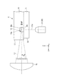
図1は、実施形態に係る粒子検出システム1の概略的な平面図である。図2は、実施形態に係る粒子検出装置100の概略的な正面図である。[Configuration of particle detector]
FIG. 1 is a schematic plan view of the
粒子検出装置100は、流体デバイスCを検出対象として流体デバイスCに照明光L1を照射し、流体デバイスCからの散乱光L2を観察することにより、流体デバイスC内の粒子に関する情報を検出する。粒子検出装置100は、光源部LS、照射部20、調整部CL、ステージ部ST、検出部30、送信部40、および制御装置5を備えている。粒子検出装置100および流体デバイスCによって粒子検出システム1が構成される。
The
以下の説明においては、ステージ部STの設置面STaと直交し、照明光L1と平行な面(不図示)と直交する方向をx方向(x軸;第3方向)、設置面STaと平行でx方向と直交する方向をy方向(y軸)、x方向およびy方向と直交する鉛直方向をz方向(z軸;第2方向)として適宜説明する。 In the following description, the direction orthogonal to the installation surface STa of the stage portion ST and orthogonal to the surface (not shown) parallel to the illumination light L1 is the x direction (x axis; third direction) and parallel to the installation surface STa. The direction orthogonal to the x direction will be appropriately described as the y direction (y axis), and the x direction and the vertical direction orthogonal to the y direction will be appropriately described as the z direction (z axis; second direction).
まず、検出対象である流体デバイスCについて説明する。
本実施形態における流体デバイスCは、一例として、検体を分析する際に用いられる電気泳動分析チップである。検体となる微粒子としては、細胞、細菌、ウィルス、細胞外小胞体(細胞外ベシクル)、合成高分子、無機物、若しくは金属を基材とする微粒子、磁性微粒子、高分子ミセル構造を有する微粒子等が挙げられる。合成高分子を基材とする微粒子としては、例えばポリスチレン等のラテックス粒子が挙げられる。無機物を基材とする微粒子としては、例えばシリカ粒子が挙げられる。金属を基材とする微粒子としては、例えば鉄製ビーズが挙げられる。磁性微粒子としては、例えば鉄、酸化鉄、ニッケル等を含む磁性を有するビーズが挙げられる。合成高分子、無機物、若しくは金属を基材とする微粒子、及び磁性微粒子のいずれも、ペプチド、タンパク質、細胞、各種化合物等で表面を修飾された粒子を含む。
本実施形態では、電気泳動分析チップとして、細胞外小胞体を分析するための細胞外小胞体分析チップを用いる場合について説明する。本明細書において、細胞外小胞体とは、エクソソーム(エキソソーム)、アポトーシス小体、マイクロベシクル等を含む、脂質小胞を意味するものとする。細胞外小胞体の大きさは直径30nmから1μm程度である。細胞外小胞体は、細胞の分泌物であり、その表面に分泌源の細胞由来のタンパク質を発現している。
以下に、エクソソームを分析する場合を例として、本実施形態に係る細胞外小胞体分析チップ(電気泳動分析チップ)について説明する。First, the fluid device C to be detected will be described.
The fluid device C in this embodiment is, for example, an electrophoresis analysis chip used when analyzing a sample. The fine particles used as samples include cells, bacteria, viruses, extracellular endoplasmic reticulum (extracellular vesicles), synthetic polymers, inorganic substances, or metal-based fine particles, magnetic fine particles, and fine particles having a polymer micelle structure. Can be mentioned. Examples of the fine particles using the synthetic polymer as a base material include latex particles such as polystyrene. Examples of the fine particles using an inorganic substance as a base material include silica particles. Examples of the fine particles using a metal as a base material include iron beads. Examples of the magnetic fine particles include beads having magnetism containing iron, iron oxide, nickel and the like. All of the fine particles based on synthetic polymers, inorganic substances, or metals, and magnetic fine particles include particles whose surface is modified with peptides, proteins, cells, various compounds, and the like.
In this embodiment, a case where an extracellular endoplasmic reticulum analysis chip for analyzing extracellular endoplasmic reticulum is used as the electrophoresis analysis chip will be described. In the present specification, the extracellular endoplasmic reticulum means a lipid vesicle including an exosome (exosome), an apoptotic body, a microvesicle, and the like. The size of the extracellular endoplasmic reticulum is about 30 nm to 1 μm in diameter. The extracellular endoplasmic reticulum is a secretion of cells, and the cell-derived protein of the secretory source is expressed on the surface thereof.
Hereinafter, the extracellular endoplasmic reticulum analysis chip (electrophoresis analysis chip) according to the present embodiment will be described as an example of analyzing exosomes.
[エクソソーム]
エクソソームは、直径30〜200nm程度の脂質小胞であり、エンドソームと細胞膜との融合体として、腫瘍細胞、樹状細胞、T細胞、B細胞等、種々の細胞から、血液、尿、唾液等の体液中に分泌される。
生体内に存在する癌細胞等の異常細胞は、その細胞膜に特有のタンパク質を発現している。エクソソームは細胞の分泌物であり、その表面に分泌源の細胞由来のタンパク質を発現している。[Exosomes]
Exosomes are lipid vesicles having a diameter of about 30 to 200 nm, and as a fusion of endosomes and cell membranes, from various cells such as tumor cells, dendritic cells, T cells, B cells, blood, urine, saliva, etc. It is secreted into body fluids.
Abnormal cells such as cancer cells existing in the living body express proteins peculiar to the cell membrane. Exosomes are cell secretions that express the source cell-derived proteins on their surface.
そこで、エクソソームの表面に発現しているタンパク質を分析することで、分泌源の細胞の異常を検出することができる。ここで、エクソソームの表面とは、細胞から分泌される脂質小胞の膜表面であって、分泌されたエクソソームが生体内の環境と接する部分をいう。 Therefore, by analyzing the protein expressed on the surface of exosomes, it is possible to detect abnormalities in the cells of the secretory source. Here, the surface of an exosome is the membrane surface of a lipid vesicle secreted from a cell, and refers to a portion where the secreted exosome comes into contact with the environment in the living body.
エクソソームは、生体内で循環している血液中で検出されるため、エクソソームを分析することで、バイオプシー検査をしなくとも、生体内の異常を検出することができる。 Since exosomes are detected in blood circulating in the living body, it is possible to detect abnormalities in the living body by analyzing the exosomes without performing a biopsy test.
[エクソソームの分析]
細胞外小胞体分析チップを用いたエクソソームの分析は、一例として次のようにして行うことができる。まず、検出対象のエクソソームを精製する。次に、エクソソームと特異的結合物質とを接触させる。ここで、特異的結合物質とは、エクソソームの表面に存在する分子に特異的に結合することができる物質を意味し、詳細は後述する。次に、細胞外小胞体分析チップを用いて、エクソソームのゼータ電位を計測し、分析を行う。本分析は、エクソソームに限らず、広く細胞外小胞体一般の分析にも適用できる。[Analysis of exosomes]
The analysis of exosomes using the extracellular endoplasmic reticulum analysis chip can be performed as follows as an example. First, the exosome to be detected is purified. The exosome is then brought into contact with the specific binding agent. Here, the specific binding substance means a substance that can specifically bind to a molecule existing on the surface of an exosome, and the details will be described later. Next, the zeta potential of the exosome is measured and analyzed using an extracellular endoplasmic reticulum analysis chip. This analysis can be applied not only to exosomes but also to the analysis of extracellular endoplasmic reticulum in general.
(特異的結合物質)
特異的結合物質としては、例えば、抗体、改変抗体、アプタマー、リガンド分子等が挙げられる。抗体としては、IgG、IgA、IgD、IgE、IgM等が挙げられる。IgGとしては、IgG1、IgG2、IgG3、IgG4等が挙げられる。IgAとしては、IgA1、IgA2等が挙げられる。IgMとしては、IgM1、IgM2等が挙げられる。改変抗体としては、Fab、F(ab’)2、scFv等が挙げられる。アプタマーとしては、ペプチドアプタマー、核酸アプタマー等が挙げられる。リガンド分子としては、エクソソームの表面に存在する検出対象分子が、レセプタータンパク質である場合の、当該レセプタータンパク質のリガンド等が挙げられる。例えば、エクソソームの表面に存在する分子がインターロイキンである場合、リガンド分子としてはGタンパク質等が挙げられる。(Specific binding substance)
Specific binding substances include, for example, antibodies, modified antibodies, aptamers, ligand molecules and the like. Examples of the antibody include IgG, IgA, IgD, IgE, IgM and the like. Examples of IgG include IgG1, IgG2, IgG3, IgG4 and the like. Examples of IgA include IgA1, IgA2 and the like. Examples of IgM include IgM1 and IgM2. Examples of the modified antibody include Fab, F (ab') 2, scFv and the like. Examples of the aptamer include peptide aptamers and nucleic acid aptamers. Examples of the ligand molecule include a ligand of the receptor protein when the detection target molecule existing on the surface of the exosome is a receptor protein. For example, when the molecule existing on the surface of the exosome is interleukin, the ligand molecule includes G protein and the like.
また、特異的結合物質は、標識物質で標識されていてもよい。標識物質としては、例えば、ビオチン、アビジン、ストレプトアビジン、ニュートラビジン、グルタチオン−S−トランスフェラーゼ、グルタチオン、蛍光色素、ポリエチレングリコール、メリト酸等の電荷分子等が挙げられる。 In addition, the specific binding substance may be labeled with a labeling substance. Examples of the labeling substance include charged molecules such as biotin, avidin, streptavidin, neutravidin, glutathione-S-transferase, glutathione, fluorescent dye, polyethylene glycol, and melitonic acid.
(エクソソームの精製)
本分析の各工程について説明する。まず、エクソソームを含有する試料から該エクソソームを精製する。試料としては、目的に応じて、血液、尿、母乳、気管支肺胞洗浄液、羊水、悪性滲出液、唾液、細胞培養液等が挙げられる。中でも、血液及び尿からは、エクソソームを精製しやすい。(Purification of exosomes)
Each step of this analysis will be described. First, the exosome is purified from a sample containing the exosome. Examples of the sample include blood, urine, breast milk, bronchoalveolar lavage fluid, amniotic fluid, malignant exudate, saliva, cell culture fluid and the like, depending on the purpose. Above all, exosomes are easily purified from blood and urine.
エクソソームを精製する方法としては、超遠心分離、限外ろ過、連続フロー電気泳動、クロマトグラフィー、μ−TAS(Micro−Total Analysis Systems)デバイスを使用する方法等が挙げられる。 Examples of the method for purifying exosomes include ultracentrifugation, ultrafiltration, continuous flow electrophoresis, chromatography, and a method using a μ-TAS (Micro-Total Analysis Systems) device.
(エクソソームと特異的結合物質との反応)
次に、エクソソームと特異的結合物質(抗体、アプタマー等)とを接触させる。エクソソームの表面に検出対象の分子が存在した場合、特異的結合物質−エクソソーム複合体が形成される。特異的結合物質を適切に選択することにより、例えば、癌、肥満、糖尿病、神経変性疾患等の疾患に関連する異常を検出することができる。また、例えば人工的に膜表面にあるペプチドやタンパク質を発現させたエクソソームに対し、そのペプチドやタンパク質に対して特異的に結合する特異的結合物質を用いるなど、機能を改変したエクソソームを評価することもできる。(Reaction between exosomes and specific binding substances)
Next, the exosome is brought into contact with a specific binding substance (antibody, aptamer, etc.). When the molecule to be detected is present on the surface of the exosome, a specific binding substance-exosome complex is formed. By appropriately selecting a specific binding substance, it is possible to detect abnormalities related to diseases such as cancer, obesity, diabetes and neurodegenerative diseases. In addition, evaluation of exosomes whose functions have been modified, for example, by using a specific binding substance that specifically binds to the peptide or protein to an exosome that artificially expresses a peptide or protein on the membrane surface. You can also.
(ゼータ電位の計測)
一例として、特異的結合物質として抗体を使用した場合について説明する。エクソソームと抗体とを反応させた後、抗体と反応させたエクソソームのゼータ電位を計測する。ゼータ電位とは、溶液中の微粒子の表面電荷である。例えば、エクソソームが負に帯電しているのに対し、抗体は正に帯電している。このため、抗体−エクソソーム複合体のゼータ電位は、エクソソーム単独のゼータ電位と比較して正にシフトしている。したがって、抗体と反応させたエクソソームのゼータ電位を測定することによって、エクソソームの膜表面における抗原の発現を検出することができる。これは、抗体に限らず、正に帯電した特異的結合物質でも同様である。(Measurement of zeta potential)
As an example, the case where an antibody is used as a specific binding substance will be described. After reacting the exosome with the antibody, the zeta potential of the exosome reacted with the antibody is measured. The zeta potential is the surface charge of the fine particles in the solution. For example, exosomes are negatively charged, whereas antibodies are positively charged. Therefore, the zeta potential of the antibody-exosome complex is positively shifted as compared with the zeta potential of the exosome alone. Therefore, the expression of the antigen on the membrane surface of the exosome can be detected by measuring the zeta potential of the exosome reacted with the antibody. This applies not only to antibodies but also to positively charged specific binding substances.
エクソソームのゼータ電位ζは、一例として、細胞外小胞体分析チップのマイクロ流路内で、エクソソームの電気泳動を行い、エクソソームの電気泳動速度Sを光学的に測定し、測定されたエクソソームの電気泳動速度Sに基づいて、以下の式(1)に示すスモルコフスキー(Smoluchowski)の式を用いて算出することができる。 As an example, the zeta potential ζ of an exosome is obtained by performing electrophoresis of the exosome in the microchannel of the extracellular vesicle analysis chip, optically measuring the electrophoresis rate S of the exosome, and measuring the electrophoresis of the exosome. Based on the velocity S, it can be calculated using the formula of Smoluchowski shown in the following formula (1).

式(1)中、Uは測定対象のエクソソームの電気泳動移動度、ε及びηは、それぞれ、サンプル溶液の誘電率及び粘性係数である。また、電気泳動移動度Uは、電気泳動速度Sをマイクロ流路内の電界強度で除して算出することができる。 In formula (1), U is the electrophoretic mobility of the exosome to be measured, and ε and η are the permittivity and viscosity coefficient of the sample solution, respectively. Further, the electrophoresis mobility U can be calculated by dividing the electrophoresis speed S by the electric field strength in the microchannel.
エクソソームの電気泳動速度Sは、一例として、エクソソームを、細胞外小胞体分析チップのマイクロ流路内で電気泳動し、一例として、レーザー光を、マイクロ流路内を流れるエクソソームに照射して、レイリー散乱光による粒子画像を取得することにより、測定することができる。レーザー光としては、一例として、波長405nm、強度150mWのものが挙げられる。 The electrophoretic rate S of the exosome is, for example, electrophoresing the exosome in the microchannel of the extracellular endoplasmic reticulum analysis chip, and irradiating the exosome flowing in the microchannel with laser light as an example, Rayleigh. It can be measured by acquiring a particle image by scattered light. As an example, the laser beam has a wavelength of 405 nm and an intensity of 150 mW.
(粒子径の計測)
エクソソームの粒子径dは、一例として、細胞外小胞体分析チップのマイクロ流路内で、エクソソームの電気泳動を行い、エクソソームの電気泳動速度Sを光学的に測定し、測定されたエクソソームの電気泳動速度Sに基づいて、以下の式(2)に示すアインシュタイン・ストークスの式を用いて算出することができる。(Measurement of particle size)
As an example, the particle size d of the exosome is obtained by performing electrophoresis of the exosome in the microchannel of the extracellular endoplasmic reticulum analysis chip, optically measuring the electrophoresis speed S of the exosome, and measuring the electrophoresis of the exosome. Based on the velocity S, it can be calculated using the Einstein-Stokes equation shown in the following equation (2).
式(2)中、dはエクソソームの粒子径、kはボルツマン定数、Tは絶対温度、ηはサンプル溶液の粘性係数、Dは微粒子の拡散係数である。すなわち、エクソソームの粒子径dは、測定対象のエクソソームのブラウン運動の状態に基づいて、算出することができる。 In formula (2), d is the particle size of the exosome, k is the Boltzmann constant, T is the absolute temperature, η is the viscosity coefficient of the sample solution, and D is the mass diffusivity of the fine particles. That is, the particle size d of the exosome can be calculated based on the state of Brownian motion of the exosome to be measured.
[細胞外小胞体分析チップの基本構造]
図3は、実施形態に係る細胞外小胞体分析チップの基本構造を示す斜視図である。図4は、図3におけるII−II線断面図である。細胞外小胞体分析チップCHは、第1リザーバ110と、第2リザーバ120と、第1リザーバ110と第2リザーバ120とを接続する泳動流路150と、基材160とを備えている。泳動流路150は、例えば、ミリ流路やマイクロ流路である。泳動流路150は、一例として、幅200μm、高さ400μm、長さ10mm程度の大きさである。泳動流路150の断面は矩形でなくてもよく、例えば、円、楕円、多角形、又はトンネル形状としてもよい。泳動流路150は、細胞外小胞体、あるいは、細胞外小胞体の表面に存在する生体分子に特異的に結合する特異的結合物質と細胞外小胞体とが相互作用してなる、特異的結合物質−細胞外小胞体複合体(一例として、抗体−エクソソーム複合体)を電気泳動するものである。特異的結合物質の一例として、抗体、アプタマー、またはこれらの組み合わせからなるものが挙げられる。アプタマーは例えば、核酸アプタマー、ペプチドアプタマーなどである。特異的結合物質が認識する分子としては、例えば抗原、膜タンパク質、核酸、糖鎖、糖脂質等が挙げられる。[Basic structure of extracellular endoplasmic reticulum analysis chip]
FIG. 3 is a perspective view showing the basic structure of the extracellular endoplasmic reticulum analysis chip according to the embodiment. FIG. 4 is a sectional view taken along line II-II in FIG. The extracellular endoplasmic reticulum analysis chip CH includes a
泳動流路150は、その一方の端部が第1リザーバ110と接続され、その他方の端部が第2リザーバ120と接続されている。また、第1リザーバ110及び第2リザーバ120は、基材160に設けられ、それぞれ電極130及び電極140を有している。例えば、電極130は第1リザーバ110の底部に設けられ、電極140は第2リザーバ120の底部に設けられている。図4に示すように、電極130及び電極140は、それぞれ泳動流路150の端部の近傍に設けられている。また、例えば、第1リザーバ110は検体(例、分析対象のエクソソーム)が導入され、第2リザーバ120は緩衝液が導入される。なお、その緩衝液は第1リザーバ110に導入されてもよい。
One end of the
本細胞外小胞体分析チップCHは、細胞外小胞体のゼータ電位を計測するのに好適である。以下に、検体又は細胞外小胞体としてエクソソームを分析する場合を例として、本細胞外小胞体分析チップを用いた、エクソソームのゼータ電位の測定方法について説明する。 The extracellular endoplasmic reticulum analysis chip CH is suitable for measuring the zeta potential of the extracellular endoplasmic reticulum. Hereinafter, a method for measuring the zeta potential of an exosome using the present extracellular endoplasmic reticulum analysis chip will be described as an example of analyzing an exosome as a sample or an extracellular endoplasmic reticulum.
まず、分析対象のエクソソームを含む試料液が、第1リザーバ110に導入される。分析対象のエクソソームは、特異的結合物質と反応させたものであってもよい。エクソソームは例えば培養上清や血清から抽出したものであり、試料液は、例えば、リン酸緩衝液(Phosphate Buffered Saline、PBS)等の緩衝液にエクソソームが懸濁されたエクソソーム懸濁液である。次に、エクソソームを含む試料液が泳動流路150に導入される。一例として、シリンジを第2リザーバ120に接続して試料液を吸引することにより、エクソソームを泳動流路150に導入することができる。次に、緩衝液を、第1リザーバ110及び第2リザーバ120に入れる。後述する液位調整手段により、第1リザーバ110と第2リザーバ120との液位(液面高)を調整して揃え、泳動流路150に生じる静水圧流の発生を防ぎ、ゼータ電位測定の精度を向上させることが可能となる。続いて、制御部(例、後述の制御装置5、又はコンピュータなど)によって電極130及び140の間に電圧を印加し、エクソソームを電気泳動する。一例として、制御部は約50V/cmの電界強度の電圧を約10秒間印加する。
First, the sample solution containing the exosome to be analyzed is introduced into the
電気泳動中に、泳動流路150にレーザー光を照射し、泳動流路150からの出射光であるエクソソームを介した散乱光を、対物レンズ等を用いて集光し、受光センサ(例、高感度カメラ)を用いて、エクソソーム又は特異的結合物質−エクソソーム複合体を撮影する。対物レンズの倍率は、一例として60倍程度である。レーザーの波長及び強度は、一例として、波長405nm、強度150mWである。
During electrophoresis, the
本実施形態における細胞外小胞体分析チップを用いることにより、特異的結合物質−エクソソーム複合体のゼータ電位の平均値だけでなく、特異的結合物質−エクソソーム複合体のゼータ電位を1粒子レベルで計測することができる。そのため、ゼータ電位の平均値からは、特異的結合物質が認識する分子(例えば、抗原等)を有するエクソソームが試料中に存在しないように思われる場合であっても、マイナーポピュレーションとして存在する、該抗原を有するエクソソームを検出することができる。 By using the extracellular endoplasmic reticulum analysis chip in the present embodiment, not only the average value of the zeta potential of the specific binding substance-exosome complex but also the zeta potential of the specific binding substance-exosome complex is measured at the single particle level. can do. Therefore, even if it seems from the mean value of the zeta potential that an exosome having a molecule (for example, an antigen) recognized by a specific binding substance does not exist in the sample, it exists as a minor population. Exosomes carrying the antigen can be detected.
[流体デバイスCの構造]
図5は、実施形態に係るステージ部STの設置面STaに流体デバイスCが設置された平面図である。図6は、実施形態に係る流体デバイスCをxz平面で部分的に断面した部分断面図である。図7は、図6におけるA−A線断面図である。[Structure of fluid device C]
FIG. 5 is a plan view in which the fluid device C is installed on the installation surface STa of the stage portion ST according to the embodiment. FIG. 6 is a partial cross-sectional view of the fluid device C according to the embodiment partially cross-sectionald in the xz plane. FIG. 7 is a cross-sectional view taken along the line AA in FIG.
図5に示すように、流体デバイスCは、平面視矩形状に形成されている。図6に示すように、流体デバイスCは、z方向に順次積み重ねられたリザーバ部材(第1基材)10および底板(第2基材)11を備えている。例えば、本実施形態における流体デバイスCは、少なくともリザーバ部材10、底板11で構成された、積層構造(積層体)である。
この場合、流体デバイスCの積層構造は二層構造となっている。また、例えば、このような流体デバイスCの積層構造は、リザーバ部材10と、底板11とを互いに貼りあわせて形成される。As shown in FIG. 5, the fluid device C is formed in a rectangular shape in a plan view. As shown in FIG. 6, the fluid device C includes a reservoir member (first base material) 10 and a bottom plate (second base material) 11 which are sequentially stacked in the z direction. For example, the fluid device C in this embodiment has a laminated structure (laminated body) composed of at least a
In this case, the laminated structure of the fluid device C has a two-layer structure. Further, for example, such a laminated structure of the fluid device C is formed by laminating the
リザーバ部材10は、外力などによって少なくとも一方向に弾性変形可能な材料で形成してもよい。リザーバ部材10の材料には、一例として、エラストマーであり、シリコーンゴム、PDMS(ポリジメチルシロキサン)などが挙げられる。底板11は、照明光L1の照射によって発生した散乱光L2が透過する材料で形成されている。底板11は、一例として、ガラス材で形成されている。
The
流体デバイスCは、長さ方向(x方向)に配列された複数(図5では3つ)のレーン2を備えている。各レーン2は、第1リザーバ12A、第2リザーバ12B、流路13および電極18A、18Bを備えている。第1リザーバ12A及び第2リザーバ12Bは、x方向に間隔をあけて配置されている。例えば、第1リザーバ12A及び第2リザーバ12Bは、流路13の流路方向に間隔をあけて配置されている。このように、複数のレーンが流路方向に(直列に)配列されていることによって、側方からの光の照射が容易となる。
複数のレーンをレーンごとに順番に分析してもよく、また、複数の検出系によって同時に分析してもよい。なお、複数のレーン2は高さ方向(z方向)に配列されていてもよい。
この場合、溶液は長さ方向(x方向)から注入されてもよく、y方向から注入されてもよい。照射光源は例えば複数あって、それぞれの光源が対応する高さのレーン2を流れる微粒子を照射する。また、少なくとも一つの照射光源から照射方向を変えることでレーン2を流れる微粒子を照射してもよい。The fluid device C includes a plurality of (three in FIG. 5)
A plurality of lanes may be analyzed in order for each lane, or may be analyzed simultaneously by a plurality of detection systems. The plurality of
In this case, the solution may be injected from the length direction (x direction) or from the y direction. There are, for example, a plurality of irradiation light sources, and each light source irradiates fine particles flowing through
ここで、レーン2が複数ある場合には、対物レンズの移動により照明光の形状を調整することにより、各レーン2に照射される照明光を調整してもよい。また、レーン2が複数ある場合には、流体デバイスCが載置されるステージの移動によって、複数レーン2のうち測定対象のレーン2を選択(切換え)する構成であってもよい。
Here, when there are a plurality of
第1リザーバ12Aは、xy平面と平行な面での断面が円形状でz方向に延在する保持空間14Aと、保持空間14Aの+z側端部から+z方向に向かうに従って漸次拡径する漏斗状の導入部15Aとを備えている。保持空間14Aは、−z側の端部が底板11と対向して開口する。保持空間14Aは、流路13と接続される。
The
第2リザーバ12Bは、xy平面と平行な面での断面が円形状でz方向に延在する保持空間14Bと、保持空間14Bの+z側端部から+z方向に向かうに従って漸次拡径する漏斗状の導入部15Bとを備えている。保持空間14Bは、−z側の端部が底板11と対向して開口する。保持空間14Bは、流路13と接続される。
The
流路13は、電気泳動用流路(電気泳動のための流路)である。流路13は、流体デバイスCの長さ方向であるy方向に延在する。流路13は、底板11と対向する側の面に保持空間14Aと保持空間14Bとを接続するように設けられている。流路13は、図7に示すように、リザーバ部材10に形成された溝部10Aと、底板11の表面(第2面)11aとで囲まれた断面矩形に形成されている。溝部10Aは、x方向に対向する側面(第1面)16a、16bと、底板11の表面11aとz方向で対向する底面(第2面)16cに囲まれて形成される。側面16a、16b、底面16cおよび溝部10Aを構成する表面11aは鏡面加工されている。第1面は、第1側面である側面16aと第2側面である側面16bとを含む。側面16aと側面16bとは、互いに向かい合っており、第1方向であるx方向に互いに離間している。
The
レーン2は、流体デバイスCの幅方向である照明光L1の光軸方向(入射方向)について、中心よりも+x側の端面17に近い側に偏って配置されている。レーン2は、入射する照明光L1の光軸方向である流体デバイスCの幅方向(図5におけるx方向)について、中心よりも照明光L1の入射側の端面17に近い側に偏って配置されている。端面17は、y方向に関して少なくともレーン2が設けられる範囲が鏡面加工されている。流路13は、一例として、幅200μm、高さ(溝部10Aの深さ)400μm、長さ10mm程度の大きさに形成されている。
The
底板11の表面11aには、保持空間14Aに臨んで電極18Aが設けられている。底板11の表面11aには、保持空間14Bに臨んで電極18Bが設けられている。電極18A及び電極18Bの素材としては、金、白金、カーボン等が挙げられる。図7に示すように、底板11における照明光L1の入射側に位置する端面(第2端面)19は、x方向について、リザーバ部材10の端面17の位置よりも、照明光L1の入射側とは逆側である−x側に離間している。
An
図1に戻り、光源部LSは、粒子に対して悪影響を及ぼさない波長として、上述したように、一例として、波長405nm、強度150mWでビーム径(ピーク値に対して1/e2となる径)0.8mmでz方向を偏向方位とするレーザー光を照明光L1として発光する。なお、照明光L1は、偏光(例えば、直線偏光など)であっても、無偏光であってもよいが、本実施形態では、垂直偏光を用い、レイリー散乱の指向性が無い構成を採る。
照明光L1は、上述した直交面と交差する方向に延びる光軸に沿って流体デバイスCに照射される。本実施形態では、照明光L1の光軸は、x方向と平行である。本実施形態の照明光L1は、x方向に延びる光軸に沿って流体デバイスCに照射される。Returning to FIG. 1, the light source unit LS has a wavelength that does not adversely affect the particles, and as described above, as an example, the beam diameter (diameter that is 1 / e2 with respect to the peak value) at a wavelength of 405 nm and an intensity of 150 mW. A laser beam having a deflection direction of 0.8 mm and a deflection direction in the z direction is emitted as illumination light L1. The illumination light L1 may be polarized (for example, linearly polarized light) or unpolarized light, but in the present embodiment, vertical polarized light is used and a configuration having no Rayleigh scattering directivity is adopted.
The illumination light L1 irradiates the fluid device C along an optical axis extending in a direction intersecting the above-mentioned orthogonal plane. In the present embodiment, the optical axis of the illumination light L1 is parallel to the x direction. The illumination light L1 of the present embodiment irradiates the fluid device C along an optical axis extending in the x direction.
図8は、実施形態に係る照射部20及び調整部CLの概略構成を示す図である。照射部20は、照明光L1の光軸に沿って順次配置されたλ/2板21およびエキスパンダレンズ22を備えている。なお、図1に示される光源部LSおよび照射部20は、照明光L1の光軸がy方向に延びているが、最終的に流体デバイスC(流路13)を照射する照明光L1はx方向に沿った光軸であるため、図8に示す照明光L1は、光軸がx方向に沿うものとして図示している。
FIG. 8 is a diagram showing a schematic configuration of the
光源部LSが発光した照明光L1は、λ/2板21を透過することで偏光方位がy方向に回転する。なお、光源部LSがy方向を偏向方位とする照明光L1を発光する場合にはλ/2板21は不要である。エキスパンダレンズ22は、対向するシリンドリカルレンズ22A、22Bを備える。シリンドリカルレンズ22A、22Bは、y方向についてはパワーを有していないため、照明光L1はy方向の幅が一定である。照明光L1のz方向の幅は、シリンドリカルレンズ22A、22Bの光軸方向の距離に応じて拡大または縮小する。本実施形態では、エキスパンダレンズ22は、照明光L1のz方向の幅を、一例として、2倍に拡大する。
The illumination light L1 emitted by the light source unit LS passes through the λ / 2
調整部CLは、エキスパンダレンズ22でz方向の幅が拡大されて入射した照明光L1を調整する。調整部CLは、光源部LSと対物レンズ31との間の光路に配置されている。また、調整部CLは、λ/2板21又はエキスパンダレンズ22と対物レンズ31との間の光路に配置されている。調整部CLは駆動機構を備えていてもよく、調整部CLが移動することで収光点を調整できてもよい。調整部CLは例えばx方向に駆動可能である。
この場合、流路13の位置が異なるチップを用いた場合であっても、流路13内に収光点が位置するように調整することが可能である。また、収光点と流路13の中心とがほぼ一致するように調整してもよく、検出部の中心部と収光点とがほぼ一致するように調整してもよい。
図9は、実施形態に係る調整部CLおよび流体デバイスCの部分詳細図である。調整部CLは、一例として、シリンドリカルレンズで構成される。調整部CLは、照明光L1のz方向の幅が流路13の内部において最小となり、且つ、流路13の照射光入射側の側面16aの位置における照明光L1の通過領域が側面16a内に限定されるように収束する収束角度に調整している。調整部CLは、照明光L1のz方向の幅が流路13の内部において最小となり、且つ、流路13の照射光入射側の側面16aの位置における照明光L1の照射領域が側面16a内に集光するような収束角度に照明光L1を調整している。また、調整部CLは、流路13の照射光射出側の側面16bの位置における照明光L1(照射光束)の通過領域が側面16b内に限定されるように収束する収束角度に調整している。
調整部CLは、流路13の照射光射出側の側面16bの位置における照明光L1(照射光束)の照射領域が側面16b内に集光するような収束角度に照明光L1を調整している。
また、調整部CLは、リザーバ部材10の端面17の位置における照明光L1の照射領域が端面17内に収束する収束角度に調整している。さらに、調整部CLは、照明光L1が流路13内の検出領域において収束点が存在するような収束角に調整している。
例えば、流路13の検出領域において検出部30の焦点深度外の照明光L1の照明光束は焦点深度内の照明光束よりも少なくなるような収束角を有する。なお、例えば、上述の直交面は、リザーバ部材10の端面17、流路13の照射光入射側の側面16a、又は流路13の照射光射出側の側面16bを含む。The adjusting unit CL adjusts the incident illumination light L1 whose width in the z direction is expanded by the
In this case, even when chips having different positions of the
FIG. 9 is a partial detailed view of the adjusting unit CL and the fluid device C according to the embodiment. The adjusting unit CL is composed of a cylindrical lens as an example. In the adjusting unit CL, the width of the illumination light L1 in the z direction is minimized inside the
The adjusting unit CL adjusts the illumination light L1 to a convergence angle such that the irradiation region of the illumination light L1 (irradiation luminous flux) at the position of the
Further, the adjusting unit CL adjusts the irradiation region of the illumination light L1 at the position of the
For example, in the detection region of the
ここで、照明光L1が光軸方向(x方向)について、流路13の中央(x=0とする)でz方向の幅が最小幅ω0となる場合、照明光L1の流路13内の媒質での収束角をθ、照明光L1の波長をλ、位置xおよび収束角θでのz方向のビーム幅をω(x、θ)、照明光L1のビームプロファイルファクタをM2、最小幅ω0となるx方向の位置から側面16aまでの距離をxLとすると、下記の式(3)、式(4)において、式(5)を満足する必要がある。
Here, when the width of the illumination light L1 in the optical axis direction (x direction) is the minimum width ω0 in the z direction at the center of the flow path 13 (x = 0), the inside of the
従って、調整部CLは、少なくとも式(3)〜(5)を満足し、且つx=xLのときのビーム幅ω(xL、θ)が側面16aのz方向の長さよりも小さく、側面16a内に収束する収束角θで照明光L1を収束させるように調整された光学特性を有するものが設置される。
Therefore, the adjusting unit CL satisfies at least the equations (3) to (5), and the beam width ω (xL, θ) when x = xL is smaller than the length of the
なお、照明光L1がガウシアン光である場合には、上記の式(3)〜(5)に含まれるビーム幅ω(x、θ)は、照明光L1の強度がピーク値に対して1/e2となる幅で規定される。収束角θが式(1)〜(3)を満足する場合でも、ピーク値に対して1/e2以下となる強度の照明光L1がビーム幅ω(xL、θ)の外側で側面16aの位置に入射するため、収束角θを設定する際はピーク値に対して1/e2以下となる強度の照明光L1のビーム幅も考慮する。
When the illumination light L1 is Gaussian light, the beam widths ω (x, θ) included in the above equations (3) to (5) are such that the intensity of the illumination light L1 is 1 / of the peak value. It is defined by the width of e2. Even when the convergence angle θ satisfies the equations (1) to (3), the illumination light L1 having an intensity of 1 / e2 or less with respect to the peak value is located outside the beam width ω (xL, θ) on the
また、検出部30によって照明光L1の光軸方向(x方向)について、流路13の全域を検出領域とするには、流路13の全体に亘って照明光L1の光束内に検出部30の焦点深度DOFが入る必要がある。照明光L1の光束内に検出部30の焦点深度DOFが入る照明光L1の光束内に検出部30の焦点深度DOFが入るためには、リザーバ部材10の端面17および流路13の側面16aの光軸に対する傾きも考慮する必要がある。図10は、実施形態に係る照明光L1がリザーバ部材10の端面17および流路13の側面16aを通過する光路を模式的に示す図である。流路13の幅全体に亘って照明光L1の光束内に検出部30の焦点深度DOF(図9参照)が入るためには、下記の式(6)を満足する必要がある。
Further, in order for the
ここで、角度δ3は、焦点面Fから見た照明光軸の仰角であり、焦点面Fから反時計回り方向を正方向とする。一方で、界面での入射角・出射角、リザーバ部材10の端面17及び流路13の側面16aのyz平面に対する傾斜角、空気中・流路デバイスCの材質中・流路中の照明光束の焦点面Fに対する仰角、および流路デバイスCの外側の媒質・流路デバイスCの材質・流路13内の媒質の屈折率には以下の関係が成立している。
Here, the angle δ3 is the elevation angle of the illumination optical axis seen from the focal plane F, and the counterclockwise direction from the focal plane F is the positive direction. On the other hand, the angle of incidence and exit at the interface, the angle of inclination of the
n1sinα1=n2sinα2
n2sinα3=n3sinα4
α1+β1=δ1
α2+β1=δ2
α3+β2=δ2
α4+β2=δ3n1sinα1 = n2sinα2
n2sinα3 = n3sinα4
α1 + β1 = δ1
α2 + β1 = δ2
α3 + β2 = δ2
α4 + β2 = δ3
ここで、
α1:自由空間からリザーバ部材10の端面17への照明光L1の入射角
α2:端面17からリザーバ部材10内の照明光L1の出射角
α3:リザーバ部材10内から流路13の壁面16aへの照明光L1の入射角
α4:壁面16aから流路13内部への照明光L1の出射角
β1:端面17の傾斜角
β2:壁面16aの傾斜角
δ1:自由空間においての照明光L1の焦点面Fからの仰角
δ2:リザーバ部材10内においての照明光L1の焦点面Fからの仰角
δ3:流路13内においての照明光L1の焦点面Fからの仰角
n1:自由空間媒質の屈折率
n2:リザーバ部材10材質の屈折率
n3:流路13内の媒質の屈折率
であり、
入射角・出射角:端面17および壁面16aへの垂線からの角度
傾斜角:焦点面Fの垂線からの角度
仰角:焦点面Fからの角度
としている。また、符号は全て反時計回り方向を正とする。here,
α1: Incident angle of illumination light L1 from free space to end
Incident angle / exit angle: Angle from the perpendicular to the
上記の式から流路13における照明光L1の仰角δ3は、以下の式(7)で表される。
From the above equation, the elevation angle δ3 of the illumination light L1 in the
従って、流路13のx方向の幅全体に亘って、照明光L1の光束内に検出部30の焦点深度DOFが入るためには、以下の式(8)を満足する必要がある。
Therefore, in order for the depth of focus DOF of the
従って、リザーバ部材10の端面17および流路13の壁面16aの傾斜角、照明光L1の仰角δ3は、自由空間媒質の屈折率n1、リザーバ部材10の材質の屈折率n2および流路13内の媒質の屈折率n3に応じて、式(8)を満足するように、選択・製造・調整されている必要がある。
Therefore, the inclination angle of the
ステージ部STは、図2に示すステージ駆動部60の駆動によって、x方向、y方向およびz方向に移動する。ステージ駆動部60の駆動は、制御装置5によって制御される。
図5に示すように、ステージ部STは、流体デバイスCが設置される設置面STaを備える。設置面STaは、xy平面と平行の面である。設置面STaは、y方向に間隔をあけて配置されている。設置面STaは、流路デバイスCのレーン2が設けられていないy方向の両端部を−Z側から支持する。流体デバイスCは、レーン2が配される領域が検出部30による−Z側からの観察に支障を来すことなく設置面STaに支持される。また、流体デバイスCにおけるレーン2に照射されるまでの照明光L1の光路にステージ部STが存在しないため、流体デバイスCに入射する照明光L1の一部がステージ部STに入射して、後述する粒子検出に悪影響を及ぼすことを抑制できる。The stage unit ST moves in the x-direction, the y-direction, and the z-direction by driving the
As shown in FIG. 5, the stage portion ST includes an installation surface STa on which the fluid device C is installed. The installation surface STa is a surface parallel to the xy plane. The installation surfaces STa are arranged at intervals in the y direction. The installation surface STa supports both ends of the flow path device C in the y direction in which the
設置面STaには、固定ピン51が突出して設けられている。固定ピン51は、流体デバイスCの長辺に当接する二つの固定ピン51aと、流体デバイスCの短辺に当接する一つの固定ピン51bとから構成される。固定ピン51aは流体デバイスCのy方向の両側の近傍にそれぞれ配置される。固定ピン51bは、+y側に位置する短辺に当接する。当該+y側に位置する固定ピン51aと固定ピン51bとが配置された角部と対角に位置する角部には、押し付けコマ52が設けられている。押し付けコマ52は、ステージ部STに対して流体デバイスCを対角方向に押し付ける。押し付けられた流体デバイスCは、固定ピン51a、51bに当接することで、流路13(レーン2)がy方向と平行になるように、xy方向に関してステージ部STに位置決めされた状態で固定される。
A fixing pin 51 is provided on the installation surface STa so as to project. The fixing pin 51 is composed of two fixing
検出部30は、対物レンズ31、撮像部32を備えている。対物レンズ31は、ステージ部STおよび流体デバイスCの−Z側に配置されている。図9に示すように、対物レンズ31は、検出軸31aがx方向について流路13の中心を通る位置に配置される。検出軸31aは、照明光L1の光軸と直交する。撮像部32は、一例として、EMCCD(Electron Multiplying Charge Coupled Device)カメラを備えており、入射する光の画像を撮像する。撮像部32は、対物レンズ31を介して入射する側方散乱光の画像情報を取得する。
送信部40は、撮像部32で撮像された画像情報を制御装置5へ送信する。The
The
[粒子検出装置の動作]
粒子検出装置100の動作は、設置工程、導入工程、照射工程、検出工程を含む。
設置工程は、流体デバイスCをステージ部STの設置面STaに設置する工程である。
具体的には、図5に示したように、押し付けコマ52により流体デバイスCを対角方向に押し付けることにより、流体デバイスCは、固定ピン51a、51bに押し付けられ、流路13(レーン2)がy方向と平行になるように、ステージ部STに位置決めされた状態で設置面STaに設置される。[Operation of particle detector]
The operation of the
The installation process is a process of installing the fluid device C on the installation surface STa of the stage portion ST.
Specifically, as shown in FIG. 5, by pressing the fluid device C diagonally by the
導入工程は、粒子を含む試料を流体デバイスCの保持空間14A、14Bおよび流路13に導入する工程である。試料としては、一例として、リン酸緩衝液等の緩衝液(媒質)にエクソソームが懸濁されたエクソソーム懸濁液を用いることができる。
試料が流路13に導入されたら、制御装置5はステージ駆動部60を駆動して、検出対象となるレーン2が照明光L1の光路および検出部30の検出軸31a上に位置させる。
検出対象となるレーン2が検出位置に移動すると、制御装置5は、電源部BTを制御して電極18A及び電極18Bに電界を印加させ、エクソソームを流路13に沿って電気泳動させる力を付与する。一例として、制御装置5は、約50V/cmの電界強度の電圧を約10秒間印加する。エクソソームの移動方向は、y方向と平行である。The introduction step is a step of introducing a sample containing particles into the holding
When the sample is introduced into the
When the
照射工程は、照明光L1をx方向と平行に流路デバイスCの流路13に照射する工程である。
照明光L1を照射する照射部20および調整部CLは、y方向の幅が一定で、上述した式(3)〜式(8)を満足する収束角θでz方向に収束するシートビーム状の照明光L1を照射する。照明光L1の最小ビーム厚(z方向のビーム幅)は、一例として、10μmである。照明光L1の最小ビーム厚(z方向のビーム幅)方向は、図7および図9のz方向またはz方向と平行な方向である。照明光L1の最小ビーム厚(z方向のビーム幅)方向は、入射面(端面17および側面16a)における照明光L1の光軸方向及び流路方向とは異なる方向であり、該光軸方向及び流路方向と直交する方向である。流路方向は、流路13が延在する方向である。流路方向は、流路13を流体が流れる方向である。
照射された照明光L1は、流体デバイスCの一方の端面(照明光入射側端面)17、流路13の側面(照明光入射側側面)16a、流路13の内部、流路13の側面(照明光射出側側面)16b、流体デバイスCの他方の端面(照明光射出側端面)27(図5参照)を順次通過する。照明光L1は、エクソソームの移動方向と直交する方向に照射される。
照射された照明光L1は、図9に示すように、流路13の内部においてz方向の幅が最小となるように収束し、且つ、流路13の側面16aの位置における照射光束の通過領域が側面16a内に限定されるように収束する。さらに、照射された照明光L1は、流路13の照明光射出側の側面16bの位置における照射光束の通過領域が側面16a内に限定されるように収束する。照明光L1は、側面16aの位置における照射領域が側面16a内に集光し、側面16bの位置における照射領域が側面16b内に集光するような収束角に調整されている。また、照射された照明光L1は、流路13における検出部30の検出領域において収束点が存在する。The irradiation step is a step of irradiating the
The
The irradiated illumination light L1 includes one end surface (illumination light incident side end surface) 17 of the fluid device C, a side surface of the flow path 13 (illumination light incident side side surface) 16a, the inside of the
As shown in FIG. 9, the irradiated illumination light L1 converges so that the width in the z direction is minimized inside the
検出工程は、照明光L1のx方向と平行な照射によって流路13内部の粒子から生じる散乱光を検出部30によって観察(イメージング)し検出する。検出部30における対物レンズ31の検出軸31aが照明光L1の光軸と直交しているため、検出部30は粒子から生じる側方散乱光を検出する。検出部30は、x方向と平行に照射された照明光L1の照射によって、x方向と垂直なz方向に向かって散乱した光を検出する。散乱光が観察された粒子の像は撮像部32で撮像される。送信部40は、撮像部32で撮像された画像情報を制御装置5へ送信する。
In the detection step, the
[制御装置の構成]
制御装置5は、粒子検出システム1を統括的に制御する。制御装置5は、ステージ駆動部60を介してステージ部STおよび流体デバイスCの移動を制御する。制御装置5は、電源部(印加部)BTを制御して、電極18A、18Bに流路13に沿った方向の電界を印加させる。また、制御装置5は、粒子検出装置100が撮像した画像を処理することにより、種々の判定を行う。この制御装置5の構成の詳細について、図11から図16を参照して説明する。[Control device configuration]
The
図11は、本実施形態の制御装置5の概略構成を示す図である。制御装置5は、演算部500と、記憶部520とを備えている。この記憶部520は、フラッシュメモリ、HDD(Hard Disk Drive)、RAM(Random Access Memory)、ROM(Read Only Memory)、レジスタなどの記憶装置を備えている。記憶部520には、演算部500が実行するプログラム(ファームウェア)が予め格納される。また、記憶部520には、演算部500が演算処理を行った演算結果が格納される。
FIG. 11 is a diagram showing a schematic configuration of the
演算部500は、CPU(Central Processing Unit)を備えており、各種の演算を行う。この演算部500は、その機能部として、取得部501と、識別部502と、ゼータ電位判定部503と、粒子径判定部504と、相関部505と、状態判定部506と、評価部507とを備えている。
The
取得部501は、粒子検出装置100が撮像した画像を取得する。具体的には、上述したように、粒子検出装置100の撮像部32は、対物レンズ31を介して入射する側方散乱光の画像を撮像して、撮像した画像の画像情報を、送信部40に出力する。取得部501は、撮像部32が撮像した側方散乱光の画像の画像情報を、送信部40を介して取得する。取得部501は、取得した画像を識別部502に出力する。
The
識別部502は、粒子検出装置100が撮像した画像のなかから、微粒子の画像を抽出する。例えば、識別部502は、取得部501から供給される画像に対して既知のフィルタ処理やパターンマッチング処理を施すことにより、微粒子の画像を抽出する。このとき、識別部502は、抽出した微粒子の画像に対して、微粒子ごとに粒子番号を付与してもよい。なお、識別対象の微粒子が細胞外小胞体である場合には、この粒子番号とは、細胞外小胞体識別子であってもよい。つまり、識別部502は、微粒子の粒子に対してラベリングを行ってもよい。このことによって後述する相関部において、微粒子のゼータ電位ζと微粒子の粒子径dとの関連付けが容易となる。このラベリングの際には、取得部が取得した複数の画像のうち、第1の時刻において撮像された画像に含まれる第1の微粒子の画像と、第1の時刻とは異なる第2の時刻において撮像された画像に含まれる第2の微粒子の画像とが、同一の微粒子を示す画像であるか否かを、媒質中のブラウン運動による微粒子の移動量に基づいて判定してもよい。また、識別部502は、ラベリングした微粒子の粒子について、粒子検出装置100が撮像した画像のフレーム間の差分に基づいて、トラッキングを行う。ここで、トラッキングとは、画像内の粒子の座標の経時的変化を追跡することをいう。識別部502が、微粒子のトラッキングを行った結果の一例を図12に示す。
The
図12は、本実施形態の記憶部520が記憶する粒子リストLS1の一例を示す図である。この粒子リストLS1には、行方向をラベリングされた粒子番号とし、列方向を撮像時刻として、各時刻における各微粒子の画像の座標(X、Y)が記憶される。この一例においては、時刻t0から、時刻t50までの各時刻における、微粒子P1から微粒子Pnまでの、各微粒子の座標が粒子リストLS1に記憶される。
FIG. 12 is a diagram showing an example of the particle list LS1 stored in the
図11に戻り、ゼータ電位判定部503は、識別部502がトラッキングした結果に基づいて、微粒子毎のゼータ電位ζを判定する。例えば、ゼータ電位判定部503は、識別部502が行った微粒子P1についてのトラッキング結果のうち、時刻t0から、時刻t1までの微粒子P1の移動速度v1に基づいて、微粒子P1のゼータ電位ζ1を判定する。
ゼータ電位判定部503は、上述の式(1)に基づいてゼータ電位ζを判定する。なお、この一例では、サンプル溶液の誘電率ε及びサンプル溶液の粘性係数ηは、予め記憶部520に記憶されている。ゼータ電位判定部503は、記憶部520に記憶されているサンプル溶液の誘電率ε及びサンプル溶液の粘性係数ηと、識別部502によるトラッキング結果から求めた微粒子の移動速度とに基づいて、微粒子のゼータ電位ζを判定する。Returning to FIG. 11, the zeta
The zeta
粒子径判定部504は、サンプル溶液中のブラウン運動による微粒子の移動量と、上述の式(2)とに基づいて、微粒子の径を判定する。ここでは、粒子径判定部504が、微粒子P1の粒子径を判定する場合の具体例について説明する。なお、この一例においては、ボルツマン定数k及びサンプル溶液の絶対温度Tは、予め記憶部520に記憶されている。粒子径判定部504は、識別部502がトラッキングした結果に基づいて、微粒子P1の移動量を算出する。また、粒子径判定部504は、算出した微粒子P1の移動量と、記憶部520に記憶されているボルツマン定数k及び絶対温度Tと、上述の式(2)とに基づいて、微粒子P1の粒子径d1を判定する。
The particle
相関部505は、ゼータ電位判定部503が判定した微粒子のゼータ電位ζと、粒子径判定部504が判定した微粒子の粒子径dとを関連付ける。具体的には、ゼータ電位判定部503において第1の微粒子に対して判定した第1のゼータ電位ζ1と、粒子径判定部504において第1の微粒子に対して判定した第1の粒子径d1とを、相関部505において第1の微粒子に関するデータとして相互に結び付ける。この相関部505が関連付けした結果である粒子相関リストLS2の一例を、図13に示す。
The
図13は、本実施形態の記憶部520が記憶する粒子相関リストLS2の一例を示す図である。この粒子相関リストLS2において、識別部502によって付与された粒子番号毎に、粒子径dと、ゼータ電位ζとが関連付けられている。相関部505は、微粒子P1について、微粒子P1の粒子径d1と、微粒子P1のゼータ電位ζ1とを関連付けて、粒子相関情報PC1(d1、ζ1)として、粒子相関リストLS2に記憶させる。また、相関部505は、微粒子P2について、微粒子P2の粒子径d2と、微粒子P2のゼータ電位ζ2とを関連付けて、粒子相関情報PC2(d2、ζ2)として、粒子相関リストLS2に記憶させる。
このように、本実施形態によれば、媒質中に存在する微粒子の状態の相関を判定することができる。FIG. 13 is a diagram showing an example of the particle correlation list LS2 stored in the
As described above, according to the present embodiment, it is possible to determine the correlation between the states of the fine particles existing in the medium.
状態判定部506は、相関部505が生成した粒子相関リストLS2に基づいて、微粒子の状態を判定する。記憶部520には、粒子径dの基準範囲と、ゼータ電位ζの基準範囲とをそれぞれ示す基準範囲情報が記憶されている。ここでは、状態判定部506による状態判定の一例として、エクソソーム以外の粒子が含まれる試料において、識別部502が識別した微粒子を、エクソソームであるか否かを判定する場合について説明する。
エクソソームの特徴として、粒径が直径30〜200nm程度の微粒子であること、そしてまた、構成因子としてシャペロン分子であるHsc70、Hsc90やテトラスパニン(CD9, CD63, CD81)が特異的に存在していることが挙げられる。
この場合、記憶部520には、粒子径のしきい値Thdが、基準範囲情報として記憶されている。また、記憶部520には、ゼータ電位のしきい値Thζが、基準範囲情報として記憶されている。これらの場合、記憶部520を基準記憶部と言い換えてもよい。このしきい値Thd、及びしきい値Thζの一例を図14に示す。The
The characteristics of exosomes are that they are fine particles with a diameter of about 30 to 200 nm, and that chaperone molecules Hsc70, Hsc90 and tetraspanin (CD9, CD63, CD81) are specifically present as constituent factors. Can be mentioned.
In this case, the particle size threshold value Thd is stored in the
図14は、本実施形態の記憶部520が記憶するしきい値の一例を示す図である。ここで、一例として、エクソソームの粒子径が、直径30〜100nm程度であり、判定対象の微粒子のうち、エクソソーム以外の微粒子の粒子径が、直径100nmを超える場合について説明する。また、ここでは、一例として、エクソソームのゼータ電位ζが、しきい値Thζ以下であり、エクソソーム以外の微粒子のゼータ電位ζが、しきい値Thζを超える場合について説明する。この一例の場合には、状態判定部506は、微粒子の粒子径、及び微粒子のゼータ電位ζに基づいて、微粒子の判定を行うことができる。なお、状態判定部506が行う微粒子の判定を、微粒子の特定と言い換えてもよい。
具体的には、この一例の場合、記憶部520には、粒子径のしきい値Thdとして、100nmが記憶されている。また、記憶部520には、ゼータ電位のしきい値Thζとして、−6mVが記憶されている。状態判定部506は、粒子相関リストLS2に記憶されている粒子相関情報PCのうち、粒子径dが、しきい値Thd以下である微粒子であり、かつ、ゼータ電位ζがしきい値Thζ以下である微粒子を、エクソソームであると判定する。一方、状態判定部506は、粒子相関リストLS2に記憶されている粒子相関情報PCのうち、粒子径dが、しきい値Thdを超える微粒子や、ゼータ電位ζが、しきい値Thζを超える微粒子を、エクソソームでないと判定する。FIG. 14 is a diagram showing an example of a threshold value stored in the
Specifically, in the case of this example, 100 nm is stored in the
また、一例として、エクソソームの粒子径が、直径30〜100nm程度であり、判定対象の微粒子のうち、エクソソーム以外の微粒子の粒子径が、直径200nmを超える場合がある。この場合には、一例として、粒子径dのしきい値Thdを150nmにすることにより、状態判定部506は、粒子径のみに基づいて微粒子の状態を判定することができる。
Further, as an example, the particle size of the exosome is about 30 to 100 nm in diameter, and the particle size of the fine particles other than the exosome among the fine particles to be determined may exceed 200 nm in diameter. In this case, as an example, by setting the threshold value Thd of the particle size d to 150 nm, the
また、直径100〜200nmの範囲には、エクソソーム以外の微粒子が含まれる場合がある。この場合には、粒子径のしきい値Thd(200nm)は、微粒子がエクソソームであるか否かを判定するための一要素として、利用することができる。
また、直径が200nmよりも大きい範囲には、単一のエクソソームが含まれていない場合がある。この場合には、粒子径のしきい値Thd(200nm)は、微粒子が単一のエクソソームであるか否かを判定するための一要素として、利用することができる。
また、直径が200nmよりも大きい範囲には、単一のエクソソームが複数個凝集した微粒子が含まれている場合がある。この場合には、粒子径のしきい値Thd(200nm)は、微粒子が単一のエクソソームであるか、凝集したエクソソームであるかを判定するための一要素として、利用することができる。
このように、基準記憶部において記憶される基準値となるしきい値を、微粒子の状態の判定のための要因として用いることができる。In addition, fine particles other than exosomes may be contained in the range of 100 to 200 nm in diameter. In this case, the particle size threshold Thd (200 nm) can be used as an element for determining whether or not the fine particles are exosomes.
Also, the range larger than 200 nm in diameter may not contain a single exosome. In this case, the particle size threshold Thd (200 nm) can be used as an element for determining whether or not the fine particles are a single exosome.
Further, in the range where the diameter is larger than 200 nm, fine particles in which a plurality of single exosomes are aggregated may be included. In this case, the particle size threshold Thd (200 nm) can be used as an element for determining whether the fine particles are single exosomes or aggregated exosomes.
In this way, the threshold value, which is the reference value stored in the reference storage unit, can be used as a factor for determining the state of the fine particles.
また、状態判定部506は、識別部502が識別した微粒子がエクソソームである場合に、このエクソソームが、抗体と反応しているか否かを判定する。この一例の場合、記憶部520には、ゼータ電位のしきい値Thζが、基準範囲情報として記憶されている。上述したように、抗体−エクソソーム複合体のゼータ電位は、エクソソーム単独のゼータ電位と比較して正にシフトしている。この場合、記憶部520には、エクソソーム単独のゼータ電位と、抗体−エクソソーム複合体のゼータ電位との間のゼータ電位(例えば、−6mv)が、ゼータ電位のしきい値Thζとして記憶されている。状態判定部506は、粒子相関リストLS2に記憶されている粒子相関情報PCのうち、微粒子のゼータ電位が、しきい値Thζ未満である微粒子を、抗体と反応していない単独のエクソソームであると判定する。一方、状態判定部506は、粒子相関リストLS2に記憶されている粒子相関情報PCのうち、微粒子のゼータ電位が、しきい値Thζ以上である微粒子を、抗体−エクソソーム複合体であると判定する。
Further, the
また、ゼータ電位のしきい値Thζ(例えば−6mV)の付近には、単体のエクソソーム及び、抗体−エクソソーム複合体以外の微粒子が存在している場合がある。この場合には、ゼータ電位のしきい値Thζ(−6mV)は、微粒子が単体のエクソソームであるか否かを判定するための一要素として、利用することができる。 Further, in the vicinity of the zeta potential threshold value Thζ (for example, −6 mV), fine particles other than a single exosome and an antibody-exosome complex may be present. In this case, the zeta potential threshold Thζ (-6 mV) can be used as an element for determining whether or not the fine particles are single exosomes.
また、状態判定部506は、粒子径dのしきい値とゼータ電位ζのしきい値とを組み合わせて、微粒子の状態を判定することもできる。具体的には、抗体−エクソソーム複合体は、単独のエクソソームと比較して、ゼータ電位が低い。このため、微粒子間に働くクーロン力は、抗体−エクソソーム複合体の方が、単独のエクソソームと比較して、弱い。この微粒子間に働くクーロン力は、微粒子間の間隔を遠ざける斥力として作用する。つまり、抗体−エクソソーム複合体の方が、単独のエクソソームと比較して、微粒子間に働く斥力が弱い。このため、抗体−エクソソーム複合体の方が、単独のエクソソームと比較して、凝集しやすい傾向がある。ここで、微粒子どうしが凝集すると、凝集した複数の微粒子が1つの微粒子として振る舞うため、ブラウン運動の運動量に変化が生じる。したがって、粒子径判定部504は、凝集した複数の微粒子を1つの微粒子として判定することにより、凝集していない場合に比べて、粒子径dが大きくなる方向にシフトする。
ここで、粒子径dが200nm以下の微粒子をエクソソームであると判定する場合を一例にして説明する。粒子径判定部504は、抗体−エクソソーム複合体を直径が200nmを超える微粒子であると判定することがある。このため、状態判定部506が粒子径dのみによって判定した場合には、抗体−エクソソーム複合体の粒子径dが、エクソソームであるか否かの粒子径dのしきい値Thdを超えるため、抗体−エクソソーム複合体がエクソソームではないと判定される場合がある。そこで、状態判定部506は、粒子径dが200nm以下の微粒子をエクソソームであると判定するとともに、粒子径dが200nmを超える微粒子であっても、ゼータ電位ζがしきい値Thζ以下である場合には、その微粒子をエクソソームであると判定する。つまり、状態判定部506は、粒子径dのしきい値Thdとゼータ電位ζのしきい値Thζとを組み合わせて、微粒子がエクソソームであるか否かを判定する。Further, the
Here, a case where fine particles having a particle diameter d of 200 nm or less are determined to be exosomes will be described as an example. The particle
また、微粒子がエクソソームであるか否かの判定には、テトラスパニン(CD9,CD81など)のように、エクソソームに特異的に結合される抗体を利用することができる。
つまり、エクソソームに対して抗体を作用させることによるゼータ電位ζ及び粒子径dの、それぞれの変化に基づいて、微粒子がエクソソームであるか否かを判定することができる。
本実施形態の粒子検出システム1は、ゼータ電位ζ及び粒子径dに基づく、上述のような評価条件を様々に組み合わせて、微粒子の評価を行うことができる利点を有する。Further, in determining whether or not the fine particles are exosomes, an antibody that specifically binds to exosomes, such as tetraspanin (CD9, CD81, etc.), can be used.
That is, it is possible to determine whether or not the fine particles are exosomes based on the respective changes in the zeta potential ζ and the particle diameter d due to the action of the antibody on the exosomes.
The
また、状態判定部506は、粒子径dのしきい値Thdとゼータ電位ζのしきい値Thζとを組み合わせた上で、識別部502によるトラッキングの結果に基づいて、微粒子の状態を判定することもできる。具体的には、状態判定部506は、単独のエクソソームに抗体を反応させ、さらに抗体−エクソソーム複合体どうしが凝集するまでの経過を、識別部502によるトラッキングの結果に基づいて追跡する。具体的には、状態判定部506は、各微粒子の粒子径dとゼータ電位ζとが、時間の経過により、図14に示す領域DM1〜領域DM4のうち、いずれの領域からいずれの領域に移動するかによって、微粒子の状態を判定する。一例として、状態判定部506は、領域DM3に存在する微粒子(例えば、単独のエクソソーム)が、領域DM2に移動した場合には、エクソソームが抗体と反応して、抗体−エクソソーム複合体に変化したと判定する。また、状態判定部506は、このエクソソームが、領域DM2から領域DM1に移動した場合には、抗体−エクソソーム複合体どうしが凝集したと判定する。
Further, the
評価部507は、微粒子の状態の良否を評価する。一例として、評価部507は、状態判定部506が判定した微粒子の状態に基づいて、微粒子の状態をAランク、Bランク、Cランクにランク付けする。ここで、Aランクとは、微粒子の粒子径d及びゼータ電位ζのいずれもが、基準範囲内に含まれる場合である。また、Bランクとは、微粒子の粒子径d及びゼータ電位ζのいずれか一方が基準範囲内に含まれない場合である。また、Cランクとは、微粒子の粒子径d及びゼータ電位ζのいずれもが基準範囲内に含まれない場合である。
The
一例として、評価部507が、微粒子が単独のエクソソームであるか否かを評価する場合について説明する。この場合、評価部507は、微粒子が領域DM3に存在する場合には、この微粒子のランクを、ランクAであると判定する。また、評価部507は、微粒子が領域DM2又は領域DM4に存在する場合には、この微粒子のランクを、ランクBであると判定する。また、評価部507は、微粒子が領域DM1に存在する場合には、この微粒子のランクを、ランクCであると判定する。
As an example, a case where the
[制御装置の動作]
次に、図15を参照して、制御装置5の動作について説明する。
図15は、本実施形態の制御装置5の動作の一例を示す図である。ここでは、粒子検出装置100が、所定の時間間隔によって側方散乱光の画像を撮像する場合について説明する。[Control device operation]
Next, the operation of the
FIG. 15 is a diagram showing an example of the operation of the
取得部501は、粒子検出装置100の撮像部32が撮像した画像を、粒子検出装置100から1枚ずつ取得する(ステップS10)。この画像には、泳動流路150を電気泳動する微粒子の画像が含まれている。また、この微粒子の画像には、エクソソームの画像が含まれている。
The
次に、識別部502は、ステップS10において取得された画像の中から、微粒子の画像を抽出し、微粒子毎に固有の粒子番号を付与する。つまり、識別部502は、微粒子をラベリングする(ステップS20)。識別部502は、すべての撮像済み画像について、ラベリングが終了したか否かを判定する(ステップS30)。識別部502は、すべての撮像済み画像について、ラベリングが終了していないと判定した場合(ステップS30;NO)には、処理をステップS10に戻し、次の画像についてラベリングを行う。識別部502は、すべての撮像済み画像について、ラベリングが終了したと判定した場合(ステップS30;YES)には、処理をステップS40に進め、識別した微粒子についてトラッキングを行う。
Next, the
次に、ゼータ電位判定部503は、識別部502がトラッキングした結果に基づいて、微粒子毎のゼータ電位ζを判定する(ステップS50)。また、粒子径判定部504は、識別部502がトラッキングした結果に基づいて、微粒子毎の粒子径を判定する(ステップS60)。なお、ステップS50と、ステップS60とは、順序が逆であってもよく、並列して実行されてもよい。
Next, the zeta
次に、相関部505は、ゼータ電位判定部503が判定した微粒子のゼータ電位ζと、粒子径判定部504が判定した微粒子の粒子径dとを関連付ける(ステップSS70)。
相関部505は、関連付けした結果を示す粒子相関リストLS2を生成し、生成した粒子相関リストLS2を記憶部520に記憶させる。相関部505は、すべての微粒子について関連付けが終了していないと判定した場合(ステップS80;NO)には、処理をステップS40に戻す。相関部505は、すべての微粒子について関連付けが終了したと判定した場合(ステップS80;YES)には、処理をステップS90に進める。Next, the
The
次に、状態判定部506及び評価部507は、ステップS70において生成された粒子相関リストLS2に基づいて、粒子の状態の判定及び評価を行う。これら、状態判定部506による粒子の状態の判定、及び評価部507による評価の具体例について、以下説明する。
Next, the
[評価の例(その1):物質の作用前後の比較]
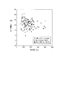
評価部507は、微粒子に対して物質を作用させる前の粒子径及びゼータ電位の分布と、作用させた後の粒子径及びゼータ電位の分布とを比較評価することができる。具体例として、微粒子がヒト繊維肉芽腫由来のエクソソームである場合に、評価部507は、このエクソソームに抗CD81抗体を作用させた場合の粒子径及びゼータ電位の分布を評価する。この具体例の場合、相関部505は、抗CD81抗体を作用させる前のエクソソームについて、ゼータ電位ζと、粒子径dとを関連付けて、粒子相関リストLS2−1を生成する。次に、相関部505は、抗CD81抗体を作用させた後のエクソソームについて、ゼータ電位ζと、粒子径dとを関連付けて、粒子相関リストLS2−2を生成する。評価部507は、抗CD81抗体を作用させる前のエクソソームについての粒子相関リストLS2−1と、抗CD81抗体を作用させた後のエクソソームについての粒子相関リストLS2−2とに基づいて、図15に示すように、粒子径及びゼータ電位の分布を出力する。[Example of evaluation (1): Comparison before and after the action of the substance]
The
図16は、本実施形態の評価部507が出力する粒子径及びゼータ電位の分布の一例を示す図である。同図に示すように、評価部507は、エクソソームに対して抗CD81抗体を作用させる前の粒子径及びゼータ電位の分布と、作用させた後の粒子径及びゼータ電位の分布とを重ねて出力する。これにより、粒子検出システム1は、微粒子に物質を作用させた場合の粒子径及びゼータ電位の分布の変化を提示することができる。
FIG. 16 is a diagram showing an example of the distribution of the particle size and the zeta potential output by the
[評価の例(その2):評価しきい値(基準範囲情報)の算出]
これまで、粒子径及びゼータ電位の評価のしきい値は、予め定められているとして説明した。評価部507は、微粒子の状態に基づいて、評価のしきい値を算出する構成であってもよい。具体例として、評価部507が、物質を作用させる前のエクソソームの状態に基づいて、評価のしきい値を算出し、この算出したしきい値に基づいて、物質を作用させた後のエクソソームについて評価する場合について、図17から図19を参照して説明する。[Evaluation example (2): Calculation of evaluation threshold (reference range information)]
So far, it has been described that the threshold values for evaluating the particle size and the zeta potential are predetermined. The
図17は、本実施形態の制御装置5aの構成の一例を示す構成図である。制御装置5aは、制御装置5の演算部500が備える各機能部に加え、計数部508と、比率算出部509と、変化率算出部510とを備える。
計数部508は、基準範囲情報が示す粒子径のしきい値Thd及びゼータ電位のしきい値Thζによって区分される領域毎に、当該領域に含まれる細胞外小胞体の数を計数する。ここで、領域の一例には、図14を参照して説明した、領域DM1〜領域DM4がある。
比率算出部509は、計数部508が計数する細胞外小胞体の数の、領域間の比率を算出する。具体的には、比率算出部509は、計数部508が計数した細胞外小胞体の数を100%とした場合の、各領域内の細胞外小胞体の数の割合を、領域毎に算出する。
変化率算出部510は、物質を作用させる前の細胞外小胞体の比率と、物質を作用させた後の細胞外小胞体の比率との変化率を、領域毎に算出する。例えば、変化率算出部510は、抗CD81抗体を作用させる前のエクソソームの領域毎の比率と、抗CD81抗体を作用させた後のエクソソームの領域毎の比率との間の変化率を、領域毎に算出する。FIG. 17 is a configuration diagram showing an example of the configuration of the
The
The
The rate of
次に、制御装置5aの動作の一例について説明する。図18は、本実施形態の制御装置の動作の変形例を示す図である。図19は、本実施形態のしきい値及び領域の一例を示す図である。
粒子径判定部504は、抗体作用前のエクソソームについて、粒子径dを判定する。評価部507は、粒子径判定部504が判定した粒子径dの平均値を算出する(ステップS110)。この一例では、評価部507は、平均粒径を120nmとして算出する。評価部507は、算出した平均粒径120nmを、粒子径のしきい値Thdとして、記憶部520に記憶させる(ステップS120)。図19に、評価部507が算出したしきい値Thdの一例を示す。
ゼータ電位判定部503は、抗体作用前のエクソソームについて、ゼータ電位ζを判定する。評価部507は、ゼータ電位判定部503が判定したゼータ電位ζの平均値を算出する(ステップS130)。この一例では、評価部507は、平均ゼータ電位を−(マイナス)13mVとして算出する。評価部507は、算出した平均ゼータ電位−13mVを、粒子径のしきい値Thζとして、記憶部520に記憶させる(ステップS140)。図19に、評価部507が算出したしきい値Thζの一例を示す。
ステップS110からステップS140の処理によって、記憶部520にしきい値が記憶される。Next, an example of the operation of the
The particle
The zeta
The threshold value is stored in the
次に、計数部508は、抗体作用前のエクソソームの各領域毎の粒子数を計数する(ステップS150)。この計数部508による計数結果の一例を、図20に示す。
Next, the
図20は、本実施形態の計数部508による計数結果の一例を示す表である。具体的には、計数部508は、抗体作用前のエクソソームについて、領域DM1〜領域DM4の粒子数を、24個、28個、16個、19個と計数する。
次に、比率算出部509は、計数部508が計数したエクソソームの粒子数に基づいて、領域間の粒子数の比率を算出する。具体的には、図20に示すように、比率算出部509は、領域DM1〜領域DM4の粒子数の比率を、28%、31%、19%、22%と算出する。FIG. 20 is a table showing an example of the counting result by the
Next, the
次に、計数部508は、抗体作用後のエクソソームの各領域毎の粒子数を計数する(ステップS160)。具体的には、計数部508は、抗体作用後のエクソソームについて、領域DM1〜領域DM4の粒子数を、13個、0個、6個、26個と計数する。
Next, the
次に、比率算出部509は、計数部508が計数したエクソソームの粒子数に基づいて、領域間の粒子数の比率を算出する。具体的には、図20に示すように、比率算出部509は、領域DM1〜領域DM4の粒子数の比率を、29%、0%、13%、58%と算出する。
Next, the
次に、変化率算出部510は、ステップS150において算出された比率と、ステップS160において算出された比率との変化率を算出する(ステップS170)。具体的には、図20に示すように、変化率算出部510は、領域DM1〜領域DM4の変化率を、+3.5%、−100%、−32%、+163%と算出する。
評価部507は、算出された変化率と、予め求められている変化率の傾向との比較により、微粒子の状態を評価する。Next, the rate of
The
なお、ここでは、評価部507は、粒子径のしきい値Thdを、粒子径の平均値に基づいて算出し、ゼータ電位のしきい値Thζを、ゼータ電位の平均値に基づいて算出したが、これに限られない。評価部507は、粒子径分布の最大値と最小値の間から選択される、粒子径を示す軸と平行な線分を、粒子径のしきい値Thdとして算出してもよい。また、評価部507は、ゼータ電位分布の最大値と最小値の間から選択される、ゼータ電位を示す軸と平行な線分を、ゼータ電位のしきい値Thζとして算出してもよい。
Here, the
[評価の例(その3):各領域の増減の要因に基づく評価]
評価部507は、抗体の作用前後における各領域の粒子数の増減について、次に示すような傾向に基づいて、微粒子の状態を評価してもよい。すなわち、領域DM1について、粒子数の増加要因には、凝集発生があり、減少要因には、抗体結合、及び凝集発生がある。また、領域DM2について、粒子数の増加要因には、凝集解消があり、減少要因には、抗体結合、及び凝集発生がある。また、領域DM3について、粒子数の増加要因には、抗体結合があり、減少要因には、凝集発生がある。また、領域DM4について、粒子数の増加要因には、抗体結合及び凝集発生があり、減少要因には、凝集解消がある。
また、評価部507は、抗体結合によって予測される各領域の粒子数の増減について、次に示すような傾向に基づいて、微粒子の状態を評価してもよい。すなわち、領域DM1について、抗体作用の結果、粒子が領域DM4に移行する。この場合、想定される機構は、抗体結合である。また、領域DM2について、抗体作用の結果、粒子数が減少する。この場合、想定される機構は、抗体結合及び凝集発生である。また、領域DM3について、抗体作用の結果、粒子が領域DM4に移行する。この場合、想定される機構は、抗体結合及び凝集発生である。また、領域DM4について、抗体作用の結果、粒子数が増加する。
この場合、想定される機構は、抗体結合及び凝集発生である。[Evaluation example (3): Evaluation based on factors of increase / decrease in each area]
The
In addition, the
In this case, the assumed mechanism is antibody binding and agglutination.
この一例の場合、上述の傾向を示すしきい値が、変化率のしきい値として記憶部520に記憶されている。評価部507は、図18から図20に示した手順により算出した増減率と、記憶部520に記憶されている変化率のしきい値とを比較することにより、微粒子の状態を評価する。
In the case of this example, the threshold value showing the above tendency is stored in the
[評価の例(その4):流路毎に異なる種類の抗体を反応させることによる評価]
また、粒子検出システム1は、複数のレーンを備えているため、レーンごとに微粒子の種類及び抗体の種類を変えることができる。具体例を図21から図23に示す。
図21は、本実施形態の複数のレーンにそれぞれ種類が異なる抗体を添加する場合の一例を示す模式図である。
図22は、本実施形態の疾患の判定パネルの一例を示す表である。
図23は、本実施形態の疾患の診断及び指導パネルの一例を示す表である。
これら図21から図23に示すように、評価部507は、レーンごとに異なる抗体を添加し、それぞれのレーンにおける微粒子の状態を評価することもできる。すなわち、粒子検出システム1によれば、目的の疾患の診断に最適な抗体の組合せを任意に選択して検査することができる。また、粒子検出システム1によれば、複数レーンを同時に評価することができるため、単一のレーンによって評価する場合に比べて、評価時間を短縮することができる。[Evaluation example (4): Evaluation by reacting different types of antibodies in each channel]
Further, since the
FIG. 21 is a schematic view showing an example of a case where different types of antibodies are added to a plurality of lanes of the present embodiment.
FIG. 22 is a table showing an example of the disease determination panel of the present embodiment.
FIG. 23 is a table showing an example of the disease diagnosis and guidance panel of the present embodiment.
As shown in FIGS. 21 to 23, the
[評価の例(その5):機能改変したエクソソームの物性評価]
評価部507は、微粒子の物性評価を行うこともできる。具体例として、評価部507が、機能を改変したエクソソームの物性評価を行う場合について、図24から図26を参照して説明する。[Example of evaluation (No. 5): Evaluation of physical properties of functionally modified exosomes]
The
図24は、本実施形態のゲート領域Gの一例を示す図である。ここで、ゲート領域Gとは、粒子径dの下限しきい値Thd1及び上限しきい値Thd2と、ゼータ電位ζの下限しきい値Thζ1及び上限しきい値Thζ2とに囲まれた領域をいう。本実施形態の評価部507は、粒子径dの下限しきい値Thd1と、粒子径dの上限しきい値Thd2との間を、粒子径dのゲート領域Gdとして、粒子の物性を評価する。また、評価部507は、ゼータ電位ζの下限しきい値Thζ1と、ゼータ電位ζの上限しきい値Thζ2との間を、ゼータ電位ζのゲート領域Gζとして、粒子の物性を評価する。以下、これらの各しきい値は、記憶部520に予め記憶されているとして説明するが、これに限られない。これらの各しきい値は、演算部500が演算によって算出してもよいし、制御装置5の外部から供給されてもよい。
FIG. 24 is a diagram showing an example of the gate region G of the present embodiment. Here, the gate region G refers to a region surrounded by the lower limit threshold value Thd1 and the upper limit threshold value Thd2 of the particle diameter d and the lower limit threshold value Thζ1 and the upper limit threshold value Thζ2 of the zeta potential ζ. The
次に、図25を参照して、演算部500による微粒子の物性評価の動作の一例を説明する。
図25は、本実施形態の演算部500による微粒子の物性評価の動作の一例を示す図である。
評価部507は、記憶部520から、粒子径dの下限しきい値Thd1及び上限しきい値Thd2と、ゼータ電位ζの下限しきい値Thζ1及び上限しきい値Thζ2とを読み出す(ステップS210)。
評価部507は、ステップS210において読み出した各しきい値に基づいて、ゲート領域を示す情報を、ディスプレイ(不図示)に表示する(図24のゲート領域Gを参照)(ステップS220)。
次に、ゼータ電位判定部503は、評価対象の微粒子のゼータ電位ζを判定する。また、粒子径判定部504は、評価対象の微粒子の粒子径dを判定する(ステップS230)。この具体例において、評価対象の微粒子とは、機能改変されたエクソソームである。
次に、相関部505は、ステップS230において判定されたゼータ電位ζと、粒子径dとを、微粒子毎に関連付けする(ステップS240)。また、相関部505は、関連付けしたゼータ電位ζと、粒子径dとを、微粒子毎にディスプレイ(不図示)に表示する。
計数部508は、ゲート領域G内に存在する微粒子の粒子数を計数する(ステップS250)。また、計数部508は、ゲート領域G外に存在する微粒子の粒子数を計数する(ステップS260)。
比率算出部509は、計数部508が計数した粒子数に基づいて、ゲート領域G内の粒子数と、ゲート領域G外の粒子数との比率を算出して(ステップS270)、処理を終了する。Next, with reference to FIG. 25, an example of the operation of evaluating the physical properties of the fine particles by the
FIG. 25 is a diagram showing an example of an operation of evaluating the physical properties of fine particles by the
The
The
Next, the zeta
Next, the
The
The
次に、評価部507による評価の一例について、図26を参照して説明する。
図26は、本実施形態の評価部507による評価の一例を示す図である。同図に示すように、評価部507は、ゲート領域G内に存在する粒子が比較的多い場合に、適合と判定し、ゲート領域G内に存在する粒子が比較的少ない場合に、不適合と判定する。つまり、評価部507は、ゲート領域G内の粒子数と、ゲート領域G外の粒子数に基づいて、評価対象の微粒子の適合性を判定する。Next, an example of evaluation by the
FIG. 26 is a diagram showing an example of evaluation by the
ここで、エクソソームを疾病の治療目的に応じて、その機能を改変する技術が知られている。例えば、エクソソームをドラッグデリバリシステムにおける薬剤のキャリアとして利用することができる。一例として、遺伝子工学的手法を用いて、ウイルスベクターを用いて任意のタンパク質遺伝子を細胞に導入し、その細胞からエクソソームを回収する。このことによってsiRNAやmiRNAなどのデリバリーキャリアとしてエクソソームを利用することが可能である。また、例えばエクソソームに特異的結合物質を結合させた機能改変エクソソームを作製し、使用することも可能である。
上述の評価部507によれば、機能改変したエクソソームが、上述のドラッグデリバリシステムに適合するものであるか否かについて、評価することができる。Here, a technique for modifying the function of an exosome according to the therapeutic purpose of a disease is known. For example, exosomes can be used as drug carriers in drug delivery systems. As an example, a genetic engineering technique is used to introduce an arbitrary protein gene into a cell using a viral vector and recover exosomes from the cell. This makes it possible to use exosomes as delivery carriers for siRNA and miRNA. It is also possible to prepare and use, for example, a function-modified exosome in which a specific binding substance is bound to an exosome.
According to the
[まとめ]
以上説明したように、本実施形態に係る粒子検出システム1は、微粒子の粒子径と、ゼータ電位とを、微粒子毎に求めるとともに、求めた粒子径とゼータ電位とを相関づける。
これにより、粒子検出システム1によれば、粒子径又はゼータ電位のいずれか一方だけでは判定が困難であった微粒子の状態を判定することができる。
また、本実施形態に係る粒子検出システム1は、照明光をレーン2の側面から入射させることにより、微粒子から生ずる散乱光を精度よく検出することができる。これにより、粒子検出システム1によれば、微粒子の粒子径やゼータ電位を精度よく判定することができる。したがって、粒子検出システム1によれば、微粒子の状態を精度よく判定することができる。[Summary]
As described above, the
As a result, according to the
Further, the
なお、上記実施形態では、電界による力を付与して粒子に流路13内を移動させる構成を例示したが、これに限定されるものではなく、媒質に流速を付与することにより、粒子を所定方向に移動させる構成、または粒子を所定方向に移動させる力を与えない構成であってもよい。
In the above embodiment, a configuration in which a force due to an electric field is applied to move the particles in the
なお、上記実施形態では、粒子から−Z側に向けて発生する散乱光を検出する構成としたが、これに限られず、例えば、+y側または−y側または+z側に向けて散乱する散乱光を検出する構成であってもよい。検出部は流路の底面側に限られず、流路の側面側でもよい。例えば、流路の側面から照明光を照射した場合に、流路の底面側から側方散乱光を検出してもよいし、流路の上面側から側方散乱光を検出してもよい。また、前方散乱光を検出する構成であってもよい。例えば、流路の側面から照明光を照射した場合に、流路の照明光出射側から後方散乱光を検出してもよく、流路の照明光出射側から前方散乱光を検出してもよい。 In the above embodiment, the scattered light generated from the particles toward the −Z side is detected, but the present invention is not limited to this, and for example, the scattered light scattered toward the + y side, the −y side, or the + z side. May be configured to detect. The detection unit is not limited to the bottom surface side of the flow path, but may be the side surface side of the flow path. For example, when the illumination light is irradiated from the side surface of the flow path, the side scattered light may be detected from the bottom surface side of the flow path, or the side scattered light may be detected from the upper surface side of the flow path. Further, the configuration may be such that the forward scattered light is detected. For example, when the illumination light is irradiated from the side surface of the flow path, the backscattered light may be detected from the illumination light emitting side of the flow path, or the forward scattered light may be detected from the illumination light emitting side of the flow path. ..
なお、上記実施形態では、長さ方向(y方向)に配列された複数のレーン2を備えた流体デバイスCを例示したが、複数のレーン2は高さ方向(z方向)に配列されていてもよい。この場合、溶液は長さ方向(x方向)から注入されてもよく、y方向から注入されてもよい。照射光源は例えば複数あって、それぞれの光源が対応する高さのレーン2を流れる微粒子を照射する。また、少なくとも一つの照射光源から照射方向を変えることでレーン2を流れる微粒子を照射してもよい。
In the above embodiment, the fluid device C having a plurality of
なお、照明光L1のz方向の幅が最小サイズとなる位置を調整するには、例えば、第2調整部として、焦点距離が異なる複数の調整部CL(レンズ)をターレット板に設け、ターレット板を回転させて所望の焦点距離を有するレンズを照明光L1の光路に位置させる構成や、ズームレンズを用いる構成を採ることができる。また、有効径の異なる調整部CLを複数用い、所望の有効径を有するレンズを照明光L1の光路に位置させる構成や可変NA絞りを用いて集光レンズの有効径を可変としてもよい。さらに、倍率の異なるエキスパンダレンズ22を複数用い、所望の有効径を有するエキスパンダレンズ22照明光L1の光路に位置させる構成や、ズームレンズを用いる構成を採って、倍率を可変としてもよい。
In order to adjust the position where the width of the illumination light L1 in the z direction becomes the minimum size, for example, as the second adjustment unit, a plurality of adjustment units CL (lenses) having different focal lengths are provided on the turret plate, and the turret plate is provided. It is possible to adopt a configuration in which a lens having a desired focal length is positioned in the optical path of the illumination light L1 by rotating the lens, or a configuration in which a zoom lens is used. Further, the effective diameter of the condenser lens may be made variable by using a plurality of adjusting units CL having different effective diameters and using a configuration in which a lens having a desired effective diameter is positioned in the optical path of the illumination light L1 or a variable NA diaphragm. Further, the magnification may be made variable by using a plurality of
なお、照明光L1の光軸がx軸と平行である構成を例示したが、これに限定されるものではなく、上述した直交面と交差する範囲であれば、例えば、x軸に対して±10度、または±5度で傾いてもよい。照明光L1の光軸がx軸と平行で側面16aと直交して入射した場合には、原理的にはレイリー散乱光の散乱角依存性が最も弱くなるが、上述したように、測定対象の粒子よりも大きい粒子からのミー散乱光をカットした場合にはノイズが低減され、照明光L1の光軸がx軸に対して傾いていた方がレイリー散乱光の信号強度が高くなる可能性がある。
Although the configuration in which the optical axis of the illumination light L1 is parallel to the x-axis is illustrated, the configuration is not limited to this, and if it is within the range intersecting the above-mentioned orthogonal plane, for example, ± with respect to the x-axis. It may be tilted at 10 degrees or ± 5 degrees. When the optical axis of the illumination light L1 is parallel to the x-axis and incident at right angles to the
なお、上記実施形態では、粒子としてエクソソームを用いる構成を例示したが、本装置および本システムは、エクソソーム以外にも適用できることは言うまでもない。例えば、本装置および本システムは、エクソソーム(細胞外小胞体)のような自己細胞由来粒子、細菌・ウィルスのような外来粒子、に代表される有機物粒子のみならず、金属・シリカのような無機物粒子まで適用範囲を広げることが可能である。 In the above embodiment, the configuration using exosomes as particles has been illustrated, but it goes without saying that this device and this system can be applied to other than exosomes. For example, this device and this system are not only organic particles such as autologous cell-derived particles such as exosomes (extracellular endoplasmic reticulum) and foreign particles such as bacteria and viruses, but also inorganic substances such as metals and silica. It is possible to extend the scope of application to particles.
なお、上記実施形態では、粒子検出システム1が、微粒子の状態の判定と、微粒子の種類の特定を行う場合について例示した。ここで、粒子検出システム1が判定する微粒子の状態には、微粒子どうしの凝集や、微粒子と抗体との結合状態等が含まれる。また、粒子検出システム1が特定する微粒子の種類には、エクソソーム、マイクロベシクル、アポトーシス小体、細胞、高分子ミセル等が含まれる。
In the above embodiment, the case where the
粒子検出装置100は、粒子から生じる側方散乱光を検出しているため、前方散乱光を受光した場合と比較してノイズの少ない画像情報が得られる。また、例えば、照明光L1が側面16aの位置における照射光束の通過領域が側面16a内に限定されずに、照明光L1の一部Kが底板11を介して流路13の内部に入射した場合には、側面16bまたは底面16cで散乱光が発生する可能性がある。側面16bまたは底面16cで発生した散乱光の信号強度は、観察対象の粒子で発生した散乱光の信号強度よりも数桁以上大きく、撮像部32のダイナミックレンジを超えてしまう。粒子を観察する状態においては、側面16bまたは底面16c(以下、壁面と称する)で発生した散乱光は撮像部32を飽和させる可能性がある。そして、この散乱光がz方向について広範囲から発生する場合、デフォーカスによる拡がりの発生のため、撮像部32上において散乱光が流路内の観察領域を大きく浸食することになる。本実施形態では、側面16aの位置において照明光L1の通過領域が側面16a内に限定され、且つ、端面17の位置において照明光L1の通過領域が端面17内に限定されるように照明光L1を収束させているため、信号強度の大きい散乱光の発生を抑制することができる。そのため、粒子検出装置100は、流路13内の粒子に関する情報を高精度で検出することができる。
Since the
また、検出部30の焦点深度DOFの外側の粒子からの散乱光は、デフォーカスのためにバックグラウンド光となり、粒子状に検出することができない。本実施形態では、流路13の内部でz方向の幅が最小となり、流路13内の観察領域外におけるアックグラウンド光を抑えているため、照明光L1で照明された粒子を高精度に検出することが可能になる。また、本実施形態では、端面17が鏡面加工されているため、端面17で散乱光がノイズとなり粒子検出精度に悪影響が及ぶことを抑制できる。また、本実施形態では、照明光L1が端面17に直交して入射しているため、光軸調整が容易になる。さらに、本実施形態では、底板11の端面19がリザーバ部材10の端面17よりも照明光L1の入射側とが逆側に離間しているため、照明光L1の一部が端面17に入射する前に端面19に入射することを回避できる。
Further, the scattered light from the particles outside the depth of focus DOF of the
なお、上述した実施形態における粒子検出装置100において、電気泳動によって微粒子を所定方向に移動させる場合について説明したが、これに限られない。例えば、粒子検出装置100は、媒質に流速を与えることによって、微粒子を所定方向に移動させてもよい。また、粒子検出装置100は、微粒子を所定方向に移動させる力を与えない構成であってもよい。
In the
また、上述した実施形態において、粒子検出装置100と制御装置5とが別体である場合について説明したが、これに限られない。粒子検出システム1において、粒子検出装置100と制御装置5とが、一体の装置であってもよい。例えば、粒子検出システム1において、制御装置5が粒子検出装置100に組み込まれるコンピュータとして構成されていてもよい。このように構成することにより、粒子検出システム1は、別体構成の場合に比較して、装置の大きさや設置面積を低減することができる。
Further, in the above-described embodiment, the case where the
なお、上述した実施形態における粒子検出装置100の一部をコンピュータで実現するようにしてもよい。その場合、この制御機能を実現するためのプログラムをコンピュータ読み取り可能な記録媒体に記録して、この記録媒体に記録されたプログラムをコンピュータシステムに読み込ませ、実行することによって実現してもよい。なお、ここでいう「コンピュータシステム」とは、粒子検出装置100に内蔵されたコンピュータシステムであって、OSや周辺機器等のハードウェアを含むものとする。また、「コンピュータ読み取り可能な記録媒体」とは、フレキシブルディスク、光磁気ディスク、ROM、CD−ROM等の可搬媒体、コンピュータシステムに内蔵されるハードディスク等の記憶装置のことをいう。さらに「コンピュータ読み取り可能な記録媒体」とは、インターネット等のネットワークや電話回線等の通信回線を介してプログラムを送信する場合の通信線のように、短時間、動的にプログラムを保持するもの、その場合のサーバやクライアントとなるコンピュータシステム内部の揮発性メモリのように、一定時間プログラムを保持しているものも含んでもよい。また上記プログラムは、前述した機能の一部を実現するためのものであってもよく、さらに前述した機能をコンピュータシステムにすでに記録されているプログラムとの組み合わせで実現できるものであってもよい。また、上述した実施形態における粒子検出装置100の各機能ブロックの一部、または全部を、LSI(Large Scale Integration)等の集積回路として実現してもよい。粒子検出装置100の各機能ブロックは個別にプロセッサ化してもよいし、一部、または全部を集積してプロセッサ化してもよい。また、集積回路化の手法はLSIに限らず専用回路、または汎用プロセッサで実現してもよい。
また、半導体技術の進歩によりLSIに代替する集積回路化の技術が出現した場合、当該技術による集積回路を用いてもよい。A part of the
Further, when an integrated circuit technology that replaces an LSI appears due to advances in semiconductor technology, an integrated circuit based on this technology may be used.
以上、添付図面を参照しながら本発明に係る好適な実施形態について説明したが、本発明は係る例に限定されないことは言うまでもない。上述した例において示した各構成部材の諸形状や組み合わせ等は一例であって、本発明の主旨から逸脱しない範囲において設計要求等に基づき種々変更可能である。 Although the preferred embodiments according to the present invention have been described above with reference to the accompanying drawings, it goes without saying that the present invention is not limited to the above examples. The various shapes and combinations of the constituent members shown in the above-mentioned examples are examples, and can be variously changed based on design requirements and the like without departing from the gist of the present invention.
1…粒子検出システム、5…制御装置、100…粒子検出装置、501…取得部、502…識別部、503…ゼータ電位判定部、504…粒子径判定部、505…相関部、506…状態判定部、507…評価部 1 ... Particle detection system, 5 ... Control device, 100 ... Particle detection device, 501 ... Acquisition unit, 502 ... Identification unit, 503 ... Zeta potential determination unit, 504 ... Particle size determination unit, 505 ... Correlation unit, 506 ... State determination Department, 507 ... Evaluation Department
Claims (20)
前記流路を移動する前記微粒子の粒子径を判定する粒子径判定部と、
前記流路を移動する前記微粒子のゼータ電位を判定するゼータ電位判定部と、
前記粒子径判定部が判定した前記微粒子毎の前記粒子径と、前記ゼータ電位判定部が判定した前記微粒子毎の前記ゼータ電位とを、前記微粒子毎に関連付けする相関部と、
前記粒子径の基準範囲と、前記ゼータ電位の基準範囲とをそれぞれ示す基準範囲情報を記憶する基準記憶部と、
前記相関部が前記微粒子毎に前記粒子径と前記ゼータ電位とを関連付けて得た相関情報と、前記基準記憶部が記憶する前記基準範囲情報とに基づいて、前記微粒子の種類又は状態の少なくとも一方を判定する状態判定部と、
を備える微粒子検出システム。 A stage unit having an installation surface on which a fluid device having a flow path through which a sample containing fine particles can move can be installed.
A particle size determination unit that determines the particle size of the fine particles moving in the flow path,
A zeta potential determination unit that determines the zeta potential of the fine particles moving in the flow path,
A correlation unit that associates the particle size of each fine particle determined by the particle size determination unit with the zeta potential of each fine particle determined by the zeta potential determination unit for each fine particle.
A reference storage unit that stores reference range information indicating the reference range of the particle size and the reference range of the zeta potential, respectively.
At least one of the types or states of the fine particles based on the correlation information obtained by the correlation unit in association with the particle diameter and the zeta potential for each fine particle and the reference range information stored in the reference storage unit. The state judgment unit that determines
A particle detection system equipped with.
前記照明光の照射により生ずる散乱光を撮像する撮像部と、
前記撮像部が撮像した画像に基づいて、前記画像に含まれる前記微粒子を前記微粒子毎に識別する識別部と、
を更に備え、
前記粒子径判定部と前記ゼータ電位判定部は、それぞれ、前記識別部が識別した前記微粒子毎に、前記粒子径と前記ゼータ電位とを判定する、請求項1に記載の微粒子検出システム。 An irradiation unit that irradiates the flow path with illumination light,
An imaging unit that captures scattered light generated by irradiation of the illumination light,
An identification unit that identifies the fine particles contained in the image for each of the fine particles based on the image captured by the imaging unit.
With more
The fine particle detection system according to claim 1, wherein the particle size determination unit and the zeta potential determination unit each determine the particle size and the zeta potential for each of the fine particles identified by the identification unit.
請求項2に記載の微粒子検出システム。 The state determination unit has at least one of the types or states of the fine particles contained in the region with respect to at least one region classified by the reference range of the particle diameter and the reference range of the zeta potential indicated by the reference range information. To judge,
The fine particle detection system according to claim 2 .
を更に備える請求項3に記載の微粒子検出システム。 The third aspect of claim 3 further includes a counting unit for counting the number of the fine particles contained in the region for each region classified by the threshold of the particle size and the threshold of the zeta potential indicated by the reference range information. The fine particle detection system described.
ある物質と反応させる前の前記微粒子について、前記比率算出部が算出する前記領域間の前記微粒子の数の比率と、前記物質と反応させた後の前記微粒子について、前記比率算出部が算出する前記領域間の前記微粒子の数の比率との変化率を算出する変化率算出部と
を更に備える請求項4に記載の微粒子検出システム。 A ratio calculation unit that calculates the ratio between the regions of the number of the fine particles counted by the counting unit, and
The ratio of the number of the fine particles between the regions calculated by the ratio calculation unit for the fine particles before being reacted with a substance, and the ratio calculation unit for the fine particles after the reaction with the substance. The fine particle detection system according to claim 4 , further comprising a change rate calculation unit for calculating the rate of change with the ratio of the number of the fine particles between regions.
前記状態判定部は、
前記相関情報と前記基準範囲情報とに基づいて、前記複合体の種類を特定する
請求項2から請求項5のいずれか一項に記載の微粒子検出システム。 The fine particles contain a complex in which a biomolecule on the surface and another substance are bound to each other.
The state determination unit
The fine particle detection system according to any one of claims 2 to 5 , which specifies the type of the complex based on the correlation information and the reference range information.
前記状態判定部は、特定した前記複合体の種類に基づいて、前記エクソソームの表面に特異的に結合した特異的結合物質を検出する
請求項6に記載の微粒子検出システム。 The fine particles are exosomes
The fine particle detection system according to claim 6 , wherein the state determination unit detects a specific binding substance specifically bound to the surface of the exosome based on the specified type of the complex.
請求項2から請求項7のいずれか一項に記載の微粒子検出システム。 The state determination unit outputs the distribution regarding the particle size and the zeta potential of each of the fine particles for the plurality of fine particles.
The fine particle detection system according to any one of claims 2 to 7 .
を更に備える請求項2から請求項8のいずれか一項に記載の微粒子検出システム。 The fine particle detection system according to any one of claims 2 to 8 , further comprising an evaluation unit that evaluates the distribution of at least one of the types or states of the fine particles based on the determination of the state determination unit.
請求項8または請求項9に記載の微粒子検出システム。 The fine particle detection system according to claim 8 or 9 , wherein the reference range information is stored in advance for each distribution of the state of the fine particles used for determination of the state determination unit.
請求項2から請求項10のいずれか一項に記載の微粒子検出システム。 The reference range information is described in any one of claims 2 to 10 , which is determined based on the distribution of the particle size and the zeta potential of the plurality of fine particles to which a substance is not bound to a biomolecule on the surface. Fine particle detection system.
前記識別部が識別した前記微粒子のブラウン運動に基づいて前記粒子径を判定する
請求項2から請求項11のいずれか一項に記載の微粒子検出システム。 The particle size determination unit
The fine particle detection system according to any one of claims 2 to 11 , wherein the particle size is determined based on the Brownian motion of the fine particles identified by the identification unit.
前記識別部が識別した前記微粒子の移動速度に基づいて前記ゼータ電位を判定する
請求項2から請求項12のいずれか一項に記載の微粒子検出システム。 The zeta potential determination unit
The fine particle detection system according to any one of claims 2 to 12 , wherein the zeta potential is determined based on the moving speed of the fine particles identified by the identification unit.
前記流路の内部において、前記照明光の前記第1方向と直交する第2方向の幅が最小となり、かつ、前記流路の照射光入射側の側面の位置における照射領域が前記側面内に収まるように前記照明光を収束させる調整部
を更に備える請求項2から請求項13のいずれか一項に記載の微粒子検出システム。 The irradiation unit irradiates the flow path with illumination light along an optical axis parallel to the first direction that is orthogonal to the installation surface and intersects the surface parallel to the flow path.
Inside the flow path, the width of the illumination light in the second direction orthogonal to the first direction is minimized, and the irradiation region at the position of the side surface of the flow path on the incident side of the irradiation light fits within the side surface. The fine particle detection system according to any one of claims 2 to 13 , further comprising an adjusting unit for converging the illumination light.
請求項2から請求項14のいずれか一項に記載の微粒子検出システム。 The fine particle detection system according to any one of claims 2 to 14 , wherein the fine particles are exosomes or extracellular endoplasmic reticulum to which another substance is not bound or bound.
前記相関部は、前記粒子径判定部が粒子径を判定した前記微粒子に対して付与された前記微粒子識別子と、前記ゼータ電位判定部がゼータ電位を判定した前記微粒子に対して付与された前記微粒子識別子との一致に基づいて、前記微粒子毎の前記粒子径と、前記ゼータ電位判定部が判定した前記微粒子毎の前記ゼータ電位とを、前記微粒子毎に関連付けする
請求項2から請求項14のいずれか一項に記載の微粒子検出システム。 The identification unit assigns a unique fine particle identifier to each of the identified fine particles.
The correlation unit includes the fine particle identifier given to the fine particles whose particle size is determined by the particle size determination unit, and the fine particles given to the fine particles whose zeta potential determination unit determines the zeta potential. Any of claims 2 to 14 , which associates the particle size of each fine particle with the zeta potential of each fine particle determined by the zeta potential determination unit for each fine particle based on the agreement with the identifier. The fine particle detection system according to item 1.
前記流路を移動する前記微粒子の粒子径を判定する粒子径判定ステップと、
前記流路を移動する前記微粒子のゼータ電位を判定するゼータ電位判定ステップと、
前記微粒子の前記粒子径と前記ゼータ電位とを、前記微粒子毎に関連付けする相関ステップと、
前記粒子径のしきい値と前記ゼータ電位のしきい値とに基づいて区分される領域を表示するステップと、
前記微粒子毎に前記粒子径と前記ゼータ電位との分布を表示するステップと、
を実行させるための微粒子検出プログラム。 For a computer having a stage with an installation surface on which a fluid device with a flow path capable of moving a sample containing fine particles can be installed.
A particle size determination step for determining the particle size of the fine particles moving in the flow path, and
A zeta potential determination step for determining the zeta potential of the fine particles moving in the flow path, and
A correlation step of associating the particle size of the fine particles with the zeta potential for each fine particle,
A step of displaying a region divided based on the particle size threshold value and the zeta potential threshold value, and
A step of displaying the distribution of the particle diameter and the zeta potential for each of the fine particles,
Fine particle detection program to execute.
を更に実行させる請求項17に記載の微粒子検出プログラム。 The fine particles according to claim 17 , further performing a counting step of counting the number of the fine particles contained in a specific region among the regions classified by the threshold of the particle size and the threshold of the zeta potential. Detection program.
前記照明光の照射により生ずる散乱光を撮像する撮像ステップと、
前記撮像ステップにおいて撮像された画像に基づいて、前記画像に含まれる前記微粒子を前記微粒子毎に識別する識別ステップと、
を更に実行させ、
前記粒子径判定ステップと前記ゼータ電位判定ステップは、それぞれ、前記識別ステップで識別された前記微粒子毎に、前記粒子径と前記ゼータ電位とを判定する、
請求項18に記載の微粒子検出プログラム。 An irradiation step of irradiating the flow path with illumination light,
An imaging step of capturing the scattered light generated by the irradiation of the illumination light, and
An identification step of identifying the fine particles contained in the image for each of the fine particles based on the image captured in the imaging step.
To execute further,
The particle size determination step and the zeta potential determination step determine the particle size and the zeta potential for each of the fine particles identified in the identification step, respectively.
The fine particle detection program according to claim 18 .
前記流路の内部において、前記照明光の前記第1方向と直交する第2方向の幅が最小となり、かつ、前記流路の照射光入射側の側面の位置における照射領域が前記側面内に収まるように前記照明光を調整する、
請求項19に記載の微粒子検出プログラム。 In the irradiation step, the flow path is irradiated with illumination light along an optical axis parallel to the first direction that is orthogonal to the installation surface and intersects a surface parallel to the flow path.
Inside the flow path, the width of the illumination light in the second direction orthogonal to the first direction is minimized, and the irradiation region at the position of the side surface of the flow path on the incident side of the irradiation light fits within the side surface. To adjust the illumination light,
The fine particle detection program according to claim 19 .
Applications Claiming Priority (3)
| Application Number | Priority Date | Filing Date | Title |
|---|---|---|---|
| JP2015087021 | 2015-04-21 | ||
| JP2015087021 | 2015-04-21 | ||
| PCT/JP2016/062591 WO2016171198A1 (en) | 2015-04-21 | 2016-04-21 | Particulate detection system and particulate detection program |
Publications (2)
| Publication Number | Publication Date |
|---|---|
| JPWO2016171198A1 JPWO2016171198A1 (en) | 2018-03-22 |
| JP6781989B2 true JP6781989B2 (en) | 2020-11-11 |
Family
ID=57143119
Family Applications (1)
| Application Number | Title | Priority Date | Filing Date |
|---|---|---|---|
| JP2017514177A Active JP6781989B2 (en) | 2015-04-21 | 2016-04-21 | Fine particle detection system and fine particle detection program |
Country Status (3)
| Country | Link |
|---|---|
| US (1) | US10295454B2 (en) |
| JP (1) | JP6781989B2 (en) |
| WO (1) | WO2016171198A1 (en) |
Families Citing this family (9)
| Publication number | Priority date | Publication date | Assignee | Title |
|---|---|---|---|---|
| DE102016013236B4 (en) * | 2016-11-07 | 2020-07-16 | Particle Metrix Gmbh | Device and method for measuring the concentration, size and zeta potential of nanoparticles in liquids in the scattered light mode and in the fluorescence mode |
| KR102565327B1 (en) * | 2016-11-07 | 2023-08-08 | 어플라이드 머티어리얼스, 인코포레이티드 | Methods and Apparatus for Detection and Analysis of Nanoparticles from Semiconductor Chamber Components |
| JP6596636B2 (en) * | 2016-12-06 | 2019-10-30 | 国立研究開発法人産業技術総合研究所 | Flow velocity distribution measuring method and particle size measuring method |
| JP6814474B2 (en) * | 2017-02-28 | 2021-01-20 | 国立大学法人 東京大学 | Electrophoretic analysis chip and electrophoretic analyzer |
| US10514331B1 (en) * | 2019-03-23 | 2019-12-24 | Horiba Instruments Incorporated | Method for determining the size of nanoparticles in a colloid |
| JP7356891B2 (en) * | 2019-06-12 | 2023-10-05 | 株式会社堀場製作所 | Particle analyzer and particle analysis method |
| US11665929B2 (en) * | 2019-06-13 | 2023-05-30 | Intel Corporation | Micro light-emitting diode displays with improved power efficiency |
| JP7421968B2 (en) * | 2020-03-17 | 2024-01-25 | リオン株式会社 | Particle measurement device and particle measurement method |
| US20220067953A1 (en) * | 2020-09-02 | 2022-03-03 | International Business Machines Corporation | Reflection-based monoscopic depth perception |
Family Cites Families (17)
| Publication number | Priority date | Publication date | Assignee | Title |
|---|---|---|---|---|
| JP2832117B2 (en) * | 1991-11-29 | 1998-12-02 | キヤノン株式会社 | Sample measuring device and sample measuring system |
| WO2001096868A2 (en) | 2000-06-12 | 2001-12-20 | Sysmex Corporation | Immunoassay and immunoassay apparatus |
| JP4812393B2 (en) * | 2005-03-04 | 2011-11-09 | 株式会社日立ハイテクノロジーズ | Fluorescent molecule measurement system |
| JP4411440B2 (en) * | 2006-06-02 | 2010-02-10 | 国立大学法人 筑波大学 | Particle characteristic measuring apparatus and particle characteristic measuring method |
| JP4982697B2 (en) * | 2007-04-12 | 2012-07-25 | 興和株式会社 | Particle measuring device |
| JP2009229103A (en) | 2008-03-19 | 2009-10-08 | Toshiba Corp | Quantification method of metal colloid |
| US20120135054A1 (en) * | 2009-06-29 | 2012-05-31 | Cornell University | Poly (Ester Ether Amide)s and Uses Thereof |
| WO2011082363A1 (en) * | 2009-12-30 | 2011-07-07 | Cargill, Incorporated | Membrane separation and purification of monatin |
| JP2011149793A (en) * | 2010-01-21 | 2011-08-04 | Ihi Corp | Zeta-potential measuring apparatus |
| WO2013056113A1 (en) * | 2011-10-13 | 2013-04-18 | The Johns Hopkins University | Nanocomposites of gold and polymers |
| EP2889623B1 (en) | 2012-08-24 | 2017-10-04 | The University of Tokyo | Exosome analysis method, exosome analysis apparatus, and use of exosome electrophoresis chip |
| WO2015099985A2 (en) * | 2013-12-23 | 2015-07-02 | The Brigham And Women's Hospital, Inc. | Cationic materials and formulations for drug delivery |
| JP6593174B2 (en) * | 2014-01-17 | 2019-10-23 | 株式会社ニコン | Fine particle analyzer, observation device, fine particle analysis program, and fine particle analysis method |
| AT515577B1 (en) * | 2014-03-12 | 2018-06-15 | Anton Paar Gmbh | Common radiation path for determining particle information through direct image analysis and differential image analysis |
| WO2016063912A1 (en) * | 2014-10-24 | 2016-04-28 | 国立大学法人東京大学 | Particle detection method, particle detection device and particle detection system |
| US9561286B2 (en) * | 2015-03-06 | 2017-02-07 | The Board Of Trustees Of The University Of Illinois | Sterically stabilized cationic nanocarrier, kits and method of use |
| US10369122B2 (en) * | 2015-05-21 | 2019-08-06 | Ohio State Innovation Foundation | Benzene-1,3,5-tricarboxamide derivatives and uses thereof |
-
2016
- 2016-04-21 WO PCT/JP2016/062591 patent/WO2016171198A1/en active Application Filing
- 2016-04-21 JP JP2017514177A patent/JP6781989B2/en active Active
-
2017
- 2017-10-17 US US15/786,450 patent/US10295454B2/en not_active Expired - Fee Related
Also Published As
| Publication number | Publication date |
|---|---|
| US20180100793A1 (en) | 2018-04-12 |
| WO2016171198A1 (en) | 2016-10-27 |
| US10295454B2 (en) | 2019-05-21 |
| JPWO2016171198A1 (en) | 2018-03-22 |
Similar Documents
| Publication | Publication Date | Title |
|---|---|---|
| JP6781989B2 (en) | Fine particle detection system and fine particle detection program | |
| US9952215B2 (en) | Exosome analysis method, exosome analysis apparatus, antibody-exosome complex, and exosome electrophoresis chip | |
| Daaboul et al. | Digital detection of exosomes by interferometric imaging | |
| Akagi et al. | On-chip immunoelectrophoresis of extracellular vesicles released from human breast cancer cells | |
| Yoshioka et al. | Ultra-sensitive liquid biopsy of circulating extracellular vesicles using ExoScreen | |
| US11648560B2 (en) | Particle separation systems and methods | |
| US10768141B2 (en) | Isoelectric focusing arrays and methods of use thereof | |
| AU2015307593B2 (en) | Particle imaging apparatus and particle imaging method | |
| US10408842B2 (en) | Subcellular western blotting of single cells | |
| WO2015029979A1 (en) | Exosome analysis method, exosome analysis chip, and exosome analysis device | |
| Undvall Anand et al. | Two-step acoustophoresis separation of live tumor cells from whole blood | |
| US20200055048A1 (en) | Optofluidic device and method for detecting circulating tumour cells | |
| JPWO2014129292A1 (en) | Bioanalytical device and biomolecule analyzer | |
| Kwon et al. | Methods to analyze extracellular vesicles at single particle level | |
| US10113948B2 (en) | Particle detection method, particle detection device and particle detection system | |
| JP2020204604A (en) | Particle analyzer and particle analysis method | |
| US20190369046A1 (en) | Electrophoretic analysis chip and electrophoretic analysis apparatus | |
| JP2017129425A (en) | Method of evaluating anticancer agent | |
| WO2015163194A1 (en) | Extracellular endoplasmic reticulum analysis chip, extracellular endoplasmic reticulum analysis method, and extracellular endoplasmic reticulum analysis device | |
| JPWO2018198470A1 (en) | Imaging target analysis apparatus, flow path structure, imaging member, imaging method, and imaging target analysis system | |
| JP6482774B2 (en) | Biological analysis device, analysis apparatus, and analysis method | |
| US10852272B2 (en) | Devices and methods using pore size modulation for detecting analytes in a fluid sample | |
| JP5943002B2 (en) | Cell detection method and cell detection system | |
| Tan | Investigating Physicochemical Principles for Sample Preparation and Detection From Single-cell Immunoblots | |
| WO2021099545A1 (en) | Nanoparticle tracking analysis as a biomarker tool in autoimmune diseases |
Legal Events
| Date | Code | Title | Description |
|---|---|---|---|
| A521 | Request for written amendment filed |
Free format text: JAPANESE INTERMEDIATE CODE: A523 Effective date: 20171117 |
|
| A521 | Request for written amendment filed |
Free format text: JAPANESE INTERMEDIATE CODE: A523 Effective date: 20190418 |
|
| A621 | Written request for application examination |
Free format text: JAPANESE INTERMEDIATE CODE: A621 Effective date: 20190418 |
|
| A131 | Notification of reasons for refusal |
Free format text: JAPANESE INTERMEDIATE CODE: A131 Effective date: 20200623 |
|
| A521 | Request for written amendment filed |
Free format text: JAPANESE INTERMEDIATE CODE: A523 Effective date: 20200821 |
|
| TRDD | Decision of grant or rejection written | ||
| A01 | Written decision to grant a patent or to grant a registration (utility model) |
Free format text: JAPANESE INTERMEDIATE CODE: A01 Effective date: 20200908 |
|
| A61 | First payment of annual fees (during grant procedure) |
Free format text: JAPANESE INTERMEDIATE CODE: A61 Effective date: 20201008 |
|
| R150 | Certificate of patent or registration of utility model |
Ref document number: 6781989 Country of ref document: JP Free format text: JAPANESE INTERMEDIATE CODE: R150 |
|
| S111 | Request for change of ownership or part of ownership |
Free format text: JAPANESE INTERMEDIATE CODE: R313117 |
|
| R350 | Written notification of registration of transfer |
Free format text: JAPANESE INTERMEDIATE CODE: R350 |
|
| S531 | Written request for registration of change of domicile |
Free format text: JAPANESE INTERMEDIATE CODE: R313531 |
|
| R350 | Written notification of registration of transfer |
Free format text: JAPANESE INTERMEDIATE CODE: R350 |
|
| R250 | Receipt of annual fees |
Free format text: JAPANESE INTERMEDIATE CODE: R250 |