JP6773302B2 - Methods, devices and computer-readable media - Google Patents
Methods, devices and computer-readable media Download PDFInfo
- Publication number
- JP6773302B2 JP6773302B2 JP2017537935A JP2017537935A JP6773302B2 JP 6773302 B2 JP6773302 B2 JP 6773302B2 JP 2017537935 A JP2017537935 A JP 2017537935A JP 2017537935 A JP2017537935 A JP 2017537935A JP 6773302 B2 JP6773302 B2 JP 6773302B2
- Authority
- JP
- Japan
- Prior art keywords
- signal
- data
- host
- data signal
- elements
- Prior art date
- Legal status (The legal status is an assumption and is not a legal conclusion. Google has not performed a legal analysis and makes no representation as to the accuracy of the status listed.)
- Active
Links
Images


Classifications
-
- G—PHYSICS
- G06—COMPUTING; CALCULATING OR COUNTING
- G06T—IMAGE DATA PROCESSING OR GENERATION, IN GENERAL
- G06T1/00—General purpose image data processing
- G06T1/0021—Image watermarking
- G06T1/005—Robust watermarking, e.g. average attack or collusion attack resistant
-
- G—PHYSICS
- G06—COMPUTING; CALCULATING OR COUNTING
- G06T—IMAGE DATA PROCESSING OR GENERATION, IN GENERAL
- G06T1/00—General purpose image data processing
- G06T1/0021—Image watermarking
- G06T1/0028—Adaptive watermarking, e.g. Human Visual System [HVS]-based watermarking
-
- G—PHYSICS
- G06—COMPUTING; CALCULATING OR COUNTING
- G06T—IMAGE DATA PROCESSING OR GENERATION, IN GENERAL
- G06T1/00—General purpose image data processing
- G06T1/0021—Image watermarking
- G06T1/005—Robust watermarking, e.g. average attack or collusion attack resistant
- G06T1/0064—Geometric transfor invariant watermarking, e.g. affine transform invariant
-
- G—PHYSICS
- G06—COMPUTING; CALCULATING OR COUNTING
- G06T—IMAGE DATA PROCESSING OR GENERATION, IN GENERAL
- G06T2201/00—General purpose image data processing
- G06T2201/005—Image watermarking
- G06T2201/0061—Embedding of the watermark in each block of the image, e.g. segmented watermarking
-
- G—PHYSICS
- G06—COMPUTING; CALCULATING OR COUNTING
- G06T—IMAGE DATA PROCESSING OR GENERATION, IN GENERAL
- G06T2201/00—General purpose image data processing
- G06T2201/005—Image watermarking
- G06T2201/0065—Extraction of an embedded watermark; Reliable detection
-
- G—PHYSICS
- G06—COMPUTING; CALCULATING OR COUNTING
- G06T—IMAGE DATA PROCESSING OR GENERATION, IN GENERAL
- G06T2201/00—General purpose image data processing
- G06T2201/005—Image watermarking
- G06T2201/0202—Image watermarking whereby the quality of watermarked images is measured; Measuring quality or performance of watermarking methods; Balancing between quality and robustness
Description
米国において、本出願は、2015年1月22日出願の米国特許仮出願第62/106,685号の利益を主張する。第62/106,685号出願は、ここで同出願の全体が引用によって本明細書に援用される。 In the United States, this application claims the benefit of US Patent Provisional Application No. 62 / 106,685 filed January 22, 2015. Application No. 62 / 106,685 is hereby incorporated herein by reference in its entirety.
本発明は、雑音の多い環境での信号通信に関し、特に電子透かしなどの、ホストメディア信号内での堅牢な信号通信に関する。 The present invention relates to signal communication in a noisy environment, and particularly to robust signal communication within a host media signal such as a digital watermark.
画像及び音声信号などのホストメディア信号を通じた信号通信の分野が十分に発達しているが、ホスト信号の知覚品質を損なわずに、十分なデータ容量を持って高信頼通信を提供することに課題が残る。この信号通信分野内で、ホスト信号での信号通信の手法は、「電子透かし」としばしば称される。電子透かしは、データチャネルがホスト又はカバー信号内に埋め込まれる一方で、例えば、そのホスト信号が人間によって知覚されるときにホストの知覚品質への埋込みの影響を最小限にする信号通信の形態を最もしばしば指す。関連して、ステガノグラフィ符号化は、データが通常の人間の観察から隠蔽されるようにデータをカバー信号(周囲背景信号を含む)で通信する方法を指す。ステガノグラフィ復号は、受信信号から隠蔽データを復元する相補的処理である。 Although the field of signal communication through host media signals such as image and audio signals is fully developed, it is a challenge to provide highly reliable communication with sufficient data capacity without impairing the perceptual quality of the host signal. Remains. Within this field of signal communication, the method of signal communication with a host signal is often referred to as "digital watermarking". A watermark is a form of signal communication in which a data channel is embedded within a host or cover signal, while minimizing the impact of the embedding on the perceived quality of the host, for example, when the host signal is perceived by humans. Most often point. Relatedly, steganography coding refers to a method of communicating data with a cover signal (including ambient background signals) so that the data is hidden from normal human observation. Steganography decoding is a complementary process that restores hidden data from a received signal.
この種類の信号通信は同様の属性又は応用目的を持つ他の信号通信技法と重複するので、電子透かしの境界は曖昧になる。静止画像、映像及び音声の様なホスト信号での信号通信のために、様々な技法及び応用が存在する。多くの応用に関して、データチャネルはデジタル的に埋め込まれ、そして抽出されるが、アナログ領域への及びアナログ領域からの変換の他に歪みに耐え切らなければならない。一般的な例は、物理的対象に適用される画像にデジタルデータを符号化すること、又は雑音の多い現場でスピーカからモバイルデバイスに送信される音声信号でデジタルデータを送信することを含む。データ信号は、レンダリング形態への変換、他の信号及び背景雑音との混合、並びに受信器のセンサ内での信号の取込みから、信号経路に沿ったあらゆる段階で歪みに直面する。幾つかの通信チャネルでは、包装若しくは文書の画像内容が無い領域内で信号を送る、又は人間の聴覚の限界(例えば、約20Hz)の若しくはその近くの周波数範囲で音声状データチャネルを通じて信号を送るときなど、無視できるホスト信号内容があることがある。他の場合では、ホスト内容内に埋め込まれるものとは意図されない1次元(1D)又は2次元(2D)バーコードの様なデータ搬送シンボルはそれでもなお、グラフィックデザインの他に機械可読データ要素を伝達するために変更される。追加的に、従来の2Dコード行列は、見えにくいインク又はニス層でコードを印刷し、そしてデータ信号を増幅するように調整される照明、センサ及び信号処理でコードを検出することによって、視覚的に目立ちにくくされている。別の例として、2Dコードは、より高解像度で印刷することによって見えにくいように構成され、そして対象に繰り返されてもよい。補助データチャネルのための追加ホストが容量、信頼性及び/又は知覚品質を上昇させるので、人間の視覚系の限界のちょうど内側又はちょうど外側の色及びより高次元マルチスペクトルバンドも活用されてもよい。冗長符号化及び誤り訂正技法の使用は、そのようなバーコード適合又はグリフコードが、知覚しにくい様に、又はコードが混合される他の視覚内容の判読性に干渉しない様に、包装、文書、ラベル及び他の種類の対象で他の画像内容と組み合わされることを可能にする。これらの種類の手法は、電子透かしであると考えられ得るものの境界を曖昧にする傾向があり、データチャネルを内部に埋め込むホスト内容が殆ど無い又は疎な応用領域に我々の堅牢な信号通信方法を拡大する。 Since this type of signal communication overlaps with other signal communication techniques with similar attributes or applications, the boundaries of watermarking are blurred. There are various techniques and applications for signal communication with host signals such as still images, video and audio. For many applications, the data channel is digitally embedded and extracted, but must withstand distortion as well as conversion to and from the analog domain. Common examples include encoding digital data into an image applied to a physical object, or transmitting digital data in an audio signal transmitted from a speaker to a mobile device in a noisy field. Data signals face distortion at every stage along the signal path, from conversion to rendering form, mixing with other signals and background noise, and capture of the signal within the sensor of the receiver. Some communication channels send signals within areas where there is no image content in the packaging or document, or through audio data channels in the frequency range at or near the limits of human hearing (eg, about 20 Hz). Sometimes there are host signal contents that can be ignored. In other cases, data-carrying symbols such as one-dimensional (1D) or two-dimensional (2D) barcodes that are not intended to be embedded within the host content nevertheless convey machine-readable data elements in addition to graphic design. To be modified. In addition, traditional 2D code matrices are visually printed by printing the code with a hard-to-see ink or varnish layer and detecting the code with illumination, sensors and signal processing that are tuned to amplify the data signal. It is made inconspicuous. As another example, the 2D code is configured to be obscured by printing at a higher resolution and may be repeated on the subject. Colors and higher dimensional multispectral bands just inside or outside the limits of the human visual system may also be utilized as additional hosts for auxiliary data channels increase capacity, reliability and / or perceptual quality. .. The use of redundant coding and error correction techniques is such that such barcode conformance or glyph code is difficult to perceive or interferes with the legibility of other visual content in which the code is mixed. , Labels and other types of objects can be combined with other image content. These types of techniques tend to blur the boundaries of what can be considered digital watermarks, providing our robust signal communication methods for applications with little or sparse host content to embed data channels inside. Expanding.
それでもやはり、本文書は、電子透かし又はデータ信号通信技法の特定の定義に限られることなく堅牢な補助データ信号通信に関係する。堅牢な信号通信の多くの応用に関して、課題は、歪みにもかかわらず信頼性を維持する、データ搬送容量を拡大する、及び十分な知覚品質を達成するという競合する目的を調和させることである。目的が対立するので、この調和は常に課題である。例えば、データ容量を増加させることは信頼性に影響を与える。信号強度を増加させて信頼性を向上させることは、ホスト信号の知覚品質を劣化させる及び/又は情報搬送容量を制限する、ホスト信号への変更をもたらすことがあり得る。 Nevertheless, this document relates to robust auxiliary data signal communication without being limited to a particular definition of digital watermarking or data signal communication techniques. For many applications of robust signal communication, the challenge is to reconcile the competing objectives of maintaining reliability despite distortion, increasing data transport capacity, and achieving sufficient perceptual quality. This harmony is always a challenge, as the objectives conflict. For example, increasing the amount of data affects reliability. Increasing the signal strength to improve reliability can result in changes to the host signal that degrade the perceived quality of the host signal and / or limit the information carrying capacity.
ホスト媒体にデータチャネルを埋め込むことの追加課題は、ホストが雑音源又はデータチャネルへの干渉になることである。幾つかの手法は、情報理論的手法を利用してホストチャネル内に補助データチャネルを符号化することによって干渉を軽減しようと試みる。例えば、ホスト信号への変更を最小限にするデータコード化パターンが選択されてもよい。これらの技法は「情報に基づく埋込み」に時には分類され、その理由は、ホスト歪みを低減させ、容量を増加させ、及び/又は信頼性を増加させてデータを埋め込むために、エンコーダ演算がホストの特定の情報特性によって通知されるからである。これらの技法は、ホスト信号干渉を軽減するための追加方法と組み合わせて利用されてもよい。 An additional challenge of embedding a data channel in a host medium is that the host becomes a noise source or interferes with the data channel. Some techniques attempt to mitigate interference by using information-theoretic techniques to encode auxiliary data channels within the host channel. For example, a data coding pattern that minimizes changes to the host signal may be selected. These techniques are sometimes categorized as "information-based embedding" because encoder operations are used to embed data in order to reduce host distortion, increase capacitance, and / or increase reliability. This is because it is notified by a specific information characteristic. These techniques may be used in combination with additional methods to mitigate host signal interference.
我々の先行の研究では、我々は、相補的信号検出又は復号演算と対にされる差分符号化を通じてホスト信号干渉を軽減するための方式を開発した。例えば、引用によって援用される、米国特許出願公開第20140142958号(音声チャネルで適用される差分符号化に関する)及び第20100150434号(画像内容の色チャネルで符号化される信号に適用される差分符号化に関する)を参照されたい。差分符号化は、データ信号要素がホストチャネル内の位置で差分関係で符号化される方式を一般に指す。これらのデータ信号要素は、ホストチャネル内の対応する埋込み位置にマッピングされる。 In our previous work, we have developed a method for reducing host signal interference through differential coding paired with complementary signal detection or decoding operations. For example, U.S. Pat. Please refer to). Difference coding generally refers to a method in which a data signal element is encoded in a difference relationship at a position in a host channel. These data signal elements are mapped to corresponding embedding locations within the host channel.
符号化のために信号要素を準備する方法が無数にあり、そしてそのため、差分符号化は多くの異なるデータ信号通信戦略に適用される。例示のため、非網羅的なリストは、コードシンボルを選択し、誤り訂正を適用し、信号要素を搬送するようにホストの信号特徴を選択することを含む。引用によって援用される米国特許第6,102,403号は、正及び負の信号要素を持つ搬送波に変調される補助データ信号の例を提供する。第20140142958号及び第20100150434号は、差分符号化を利用する方法の異なる例を例示する。 There are innumerable ways to prepare signal elements for coding, and therefore differential coding applies to many different data signal communication strategies. For illustration purposes, the non-exhaustive list includes selecting code symbols, applying error correction, and selecting the host's signal features to carry the signal elements. US Pat. No. 6,102,403, incorporated by reference, provides an example of ancillary data signals modulated onto a carrier wave with positive and negative signal elements. No. 201401424958 and No. 2011054034 illustrate different examples of methods that utilize differential coding.
信号検出及びデータ抽出処理が差分配置を利用してホスト信号を抑制すると、ホスト信号干渉が軽減されることができる。復号処理でのこの演算を容易にするために、ホスト信号の値が相関されるホスト信号の埋込み位置に差分符号化が適用される。相関されたホスト信号成分を相殺しつつ、差分符号化された情報を建設的に組み合わせる受信信号への復号演算によってホストは抑制され、ホストに対するデータ信号の信号対雑音比を増加させる。これらの種類の演算の例が第20140142958号及び第20100150434号に提供される。 If the signal detection and data extraction processing suppress the host signal by utilizing the difference arrangement, the host signal interference can be reduced. To facilitate this operation in the decoding process, differential coding is applied to the embedding position of the host signal with which the values of the host signal are correlated. The host is suppressed by the decoding operation to the received signal, which constructively combines the differentially encoded information while canceling the correlated host signal components, increasing the signal-to-noise ratio of the data signal to the host. Examples of these types of operations are provided in 201401424958 and 2010015434.
信号信頼性を向上させるためのこれらの技法は、埋め込まれたデータ信号が同期を難しくする方法で歪められるおそれがある応用で実装するのがより難しくなる。そのような歪みは、埋め込まれた信号の一部をトリミングする若しくは切り捨てる、又は埋め込まれた信号の構造を曲げる(例えば、射影変換を含む、幾何学的又は時間的歪み)ことがあり得る。応用要件は、例えば、データ信号がホスト信号の任意の位置での小さい部分及び幾何学変換(透視変換を含む)から確実に復元されるように要求してもよい。カメラ又はスキャナにおける2Dセンサでの対象又は文書の画像取込みは、対象の印刷、変形及び劣化でもたらされる歪みに加えて、信号の幾何学的歪み及びトリミングをもたらす。周囲音声の音声取込みは、音声を発生し、音声を圧縮し、そして音声を周囲雑音及びエコーと混合する際にもたらされる歪みに加えて、時間的歪みを持つ信号をトリミング及びサンプリングする。幾つかの応用は、ホスト信号の流れがデータの流れに信頼できるチャネルを提供するように、ホストの部分が異なるデータを伝達することを更に必要とする。 These techniques for improving signal reliability are more difficult to implement in applications where embedded data signals can be distorted in ways that make synchronization difficult. Such distortion can trim or truncate a portion of the embedded signal, or bend the structure of the embedded signal (eg, geometric or temporal distortion, including projective transformations). Application requirements may require, for example, to ensure that the data signal is restored from a small portion of the host signal at any position and geometric transformations (including perspective transformations). Image capture of an object or document with a 2D sensor in a camera or scanner results in geometric distortion and trimming of the signal, in addition to the distortion caused by printing, deformation and degradation of the object. Ambient audio capture trims and samples signals with temporal distortion, in addition to the distortion that occurs when producing audio, compressing audio, and mixing audio with ambient noise and echo. Some applications further require parts of the host to carry different data so that the flow of the host signal provides a reliable channel for the flow of data.
この歪みは、データチャネルが歪みに堅牢であるように設計されることを要求する。この要求を満たす1つの方法は、幾何学的若しくは時間的歪みに堅牢であるホストの属性を利用する、又は歪みに堅牢であるホスト変調方式を利用する符号化戦略を使用することである。加えて、符号化信号の設計は、検出及び同期を容易にする信号構造を提供する必要がしばしばある。この信号構造は、そうでなければデータが符号化され得るチャネルの部分をその信号構造が占有する程度に、データ容量を制限する。信号通信方式内に同期成分を導入することの別の意味は、これらの成分が、例えば、人間が知覚できる不必要な要素を導入することによって知覚品質を劣化させることがあり得ることである。幾つかの方式では、同期信号は、チャネルでデータ搬送信号に干渉することもある。データ信号容量に実質的に干渉することなく、脱同期に堅牢でもあるデータ信号通信の必要がある。 This distortion requires the data channel to be designed to be distortion resistant. One way to meet this requirement is to use a coding strategy that utilizes the attributes of the host that are robust to geometric or temporal distortion, or the host modulation scheme that is robust to distortion. In addition, the design of encoded signals often needs to provide a signal structure that facilitates detection and synchronization. This signal structure limits the data capacity to the extent that the signal structure occupies a portion of the channel on which the data can otherwise be encoded. Another implication of introducing synchronous components within a signal communication scheme is that these components can degrade perceptual quality, for example by introducing unnecessary elements that humans can perceive. In some schemes, the sync signal may also interfere with the data carrier signal on the channel. There is a need for data signal communication that is also robust to desynchronization without substantially interfering with the data signal capacity.
信号通信方式の応用は、他のものに加えて上述した考慮事項の何らかの組合せを強調する固有の設計制約条件を有する傾向がある。例示のため、我々は少数の例を提供するが、それらの例に我々の範囲を限定する意図はない。1つの応用領域は、物理的対象でデータ信号を伝達し、そしてモバイルデバイス又は他の民生用電子機器のセンサから感知される信号からそのデータ信号を読み取ることである。物理的対象で信号を伝達する領域では、堅牢性要件は、圧縮の様なデジタル処理、対象に信号を適用(例えば、2D又は更には3D湾曲又は不規則表面への2D及び3D印刷、打刻、エッチング)する際に及び対象から信号を感知する際に直面される劣化による歪みに耐え切ることができるデータの能力を含む。 Applications of signal communication schemes tend to have unique design constraints that emphasize some combination of the considerations mentioned above in addition to others. For illustration purposes, we provide a few examples, but we do not intend to limit our scope to those examples. One application area is to transmit a data signal to a physical object and read the data signal from a signal sensed by a sensor in a mobile device or other consumer electronic device. In areas where signals are transmitted by physical objects, robustness requirements apply digital processing such as compression, applying signals to objects (eg, 2D or even 3D curved or irregular surface 2D and 3D printing, stamping). Includes the ability of data to withstand the distortions caused by the degradation faced during (etching) and when sensing signals from objects.
別の応用領域は、映像ディスプレイ又は音声スピーカ出力で信号を伝達し、そしてモバイルデバイス又は他の民生用電子製品のセンサから感知される信号からその伝達信号を読み取ることである。画像及び音声状の信号通信は、これらの信号種類に固有の課題を提示する。印刷技術は、利用されるインクの種類及び色による制限、版面間の位置合せ、並びにデータチャネル(線画、階調表現、スクリーン角度、ドットゲインなど)を保持する印刷基本要素の印刷品質及び解像度に対する制限を含む、基材へのインクの適用の制御に対する他の制限を引き起こす。表示技術は、画面解像度、色形式、画面形式(アスペクト比、キーストーニングなどを含む)、リフレッシュレートなどに関する制限を引き起こす。目標ホスト信号内容も制限を引き起こす。画像ベースの信号通信に関しては、像若しくはアートワークの性質、又はその欠如が利用できるデータ符号化チャネルを制限する。文書内容は包装又はラベル内容とは異なる。映像形式及びコーデック、並びに映像内容品質及びデータレートも変化する。音声信号通信は、特に雑音の多い環境では、異なる形態の雑音、歪み及び干渉に関して、他の課題を提示する。 Another area of application is to transmit a signal on a video display or audio speaker output and read the transmitted signal from a signal sensed by a sensor in a mobile device or other consumer electronics product. Image and audio signal communication presents challenges specific to these signal types. Printing techniques are limited by the type and color of ink used, alignment between plates, and print quality and resolution of basic printing elements that retain data channels (line art, gradation representation, screen angle, dot gain, etc.). It causes other restrictions on the control of the application of ink to the substrate, including restrictions. Display technologies impose restrictions on screen resolution, color formats, screen formats (including aspect ratios, keystones, etc.), refresh rates, and so on. The content of the target host signal also causes limitations. For image-based signal communication, the nature of the image or artwork, or lack thereof, limits the available data coding channels. The document content is different from the packaging or label content. Video formats and codecs, as well as video content quality and data rates, also change. Audio signal communication presents other challenges with respect to different forms of noise, distortion and interference, especially in noisy environments.
信号通信方式の設計は、符号化及び復号のためのデジタル回路、プロセッサ及びメモリへの制約によって引き起こされる実際的課題も考慮しなければならない。これらの課題は、計算効率、電力消費、メモリ消費、メモリ帯域幅、ネットワーク帯域幅の使用、ハードウェア回路網又はプログラマブルプロセッサ/回路網のコスト、信号送信器及び受信器、機器内でエンコーダ及びデコーダを設計及び集積化するコストなどを含む。例えば、幾つかの符号化方式は、最適化された符号化又は復号を提供するかもしれないが、例えば、ホスト信号が送信、受信、更新されている、又は複数の他の信号処理演算で同時に処理されているとき、それらの符号化方式はリアルタイムでの符号化又は復号には遅過ぎるので、適用できないかもしれない。 The design of the signal communication scheme must also take into account the practical challenges posed by constraints on digital circuits, processors and memory for encoding and decoding. These challenges include computational efficiency, power consumption, memory consumption, memory bandwidth, network bandwidth usage, hardware network or programmable processor / network costs, signal transmitters and receivers, encoders and decoders within equipment. Includes costs for designing and integrating. For example, some coding schemes may provide optimized coding or decoding, for example, a host signal being transmitted, received, updated, or simultaneously in multiple other signal processing operations. When being processed, those coding schemes are too slow for real-time coding or decoding and may not be applicable.
本文書では、我々は、信号を発生し、そしてそれらの信号をデータチャネルで符号化及び復号するための方式を含む、様々な変調方式を詳述する。我々は、堅牢であり、知覚品質制約を達成するのに柔軟であり、且つ向上されたデータ容量を提供する様にホスト信号又は雑音の多い環境内でデータチャネルを符号化する差分変調方式を記載する。エンコーダによって適用される差分配置は、デコーダが、符号化データチャネルを検出、同期及び抽出するときにホスト信号又は他の背景信号干渉を抑制することを可能にする。差分配置は、データ信号から形成されるか又はデータ信号に相補的である黙示的又は明示的な同期成分の組込みも可能にする。 In this document, we detail various modulation schemes, including methods for generating signals and encoding and decoding those signals in a data channel. We describe a differential modulation scheme that encodes a data channel in a host signal or noisy environment to be robust, flexible to achieve perceptual quality constraints, and to provide improved data capacity. To do. The differential arrangement applied by the encoder allows the decoder to suppress host signal or other background signal interference when detecting, synchronizing and extracting encoded data channels. The differential arrangement also allows the incorporation of implied or explicit synchronization components that are formed from or complementary to the data signal.
本発明の一態様は、ホスト画像信号において補助データ(auxiliary data)を符号化する方法である。本方法は、可変データ要素から構成される補助データ信号を発生する。補助データ信号は、可変データ要素の各々をホスト画像信号内の複数のブロックにマッピングする。各ブロックは、ホスト画像信号内の隣接する埋込み位置を備える。各可変データ要素に関して、方法は、可変データ要素に従ってホスト画像信号を変調して可変データ要素を対応する複数のブロックに埋め込む。対応する複数のブロックの各々内で、変調処理は、各ブロック内の非隣接の埋込み位置における可変データ要素間の差分関係を確立することによってホスト画像を変調する。 One aspect of the present invention is a method of encoding auxiliary data in a host image signal. The method generates an auxiliary data signal composed of variable data elements. The auxiliary data signal maps each of the variable data elements to multiple blocks within the host image signal. Each block comprises adjacent embedding positions within the host image signal. For each variable data element, the method modulates the host image signal according to the variable data element and embeds the variable data element in the corresponding blocks. Within each of the corresponding blocks, the modulation process modulates the host image by establishing a differential relationship between the variable data elements at non-adjacent embedding positions within each block.
装置、デジタル論理モジュール及びプログラムプロセッサモジュールを含め、本技術の様々な代替形態が記載される。 Various alternatives of the technology are described, including devices, digital logic modules and program processor modules.
信号エンコーダ及びデコーダ
図1は、ホスト信号にデータ信号を符号化するための信号エンコーダのブロック図である。図2は、ホスト信号からデータ信号を抽出するための共存する信号デコーダのブロック図である。
Signal Encoder and Decoder FIG. 1 is a block diagram of a signal encoder for encoding a data signal into a host signal. FIG. 2 is a block diagram of coexisting signal decoders for extracting data signals from host signals.
信号エンコーダ及びデコーダが多くの応用に関してデータチャネルを通信するために使用されてもよいのに対して、我々の特有の焦点はホスト画像又は音声型信号での堅牢な信号通信であった。符号化及び復号は典型的にデジタル的に適用されるが、信号は、デジタルアナログ変換及びアナログデジタル変換に耐え切るのを期待される。例えば、エンコーダは、印刷画像、表示画像若しくは映像、又は音声トランスデューサ若しくはスピーカの出力などのレンダリング形態に変換される変調画像又は音声状信号を発生する。復号前に、受信装置がカメラ又はマイクロホンなどのセンサを有して、変調信号を取り込み、取り込んだ信号を電気信号に変換し、この電気信号がデジタル化され、次いでデコーダによって処理される。 Whereas signal encoders and decoders may be used to communicate data channels for many applications, our unique focus has been robust signal communication with host image or audio signals. Although coding and decoding are typically applied digitally, the signal is expected to withstand digital-to-analog and analog-to-digital conversions. For example, the encoder produces a printed image, a display image or video, or a modulated image or audio signal that is converted into a rendering form such as an audio transducer or speaker output. Prior to decoding, the receiving device has a sensor such as a camera or microphone to capture the modulated signal, convert the captured signal into an electrical signal, which is digitized and then processed by the decoder.
信号エンコーダへの入力は、ホスト信号150及び補助データ152を含む。エンコーダの目的は、知覚品質を維持しつつ、ホスト信号の単位当たり所望の容量で堅牢な信号を符号化することを含む。幾つかの場合には、ホスト信号の変動性又は存在はほぼ無くてもよく、この場合、一方ではホスト干渉が殆ど無いが、データチャネルの存在をマスクするホスト内容が殆ど無い。幾つかの例は、それほど画像変動性が無い包装デザイン(例えば、単一の均等色)を含む。
The input to the signal encoder includes a
補助データ152は、場合により通信を容易にするために使用される他のプロトコルデータと共にデータチャネルで伝達されるべき可変データ情報を含む。
プロトコルは、信号が堅牢性、知覚品質又はデータ容量のために構造化及び符号化される様式を定義する。何れの所与の応用に関しても、単一のプロトコル又は2つ以上のプロトコルがあってもよい。複数のプロトコルの例は、チャネルの異なるバージョン、異なるチャネル種類(例えば、ホスト内の数個の電子透かし層)がある場合を含む。異なるバージョンは異なる堅牢性符号化技法又は異なるデータ容量を利用してもよい。プロトコルセレクタモジュール154は、データ信号を発生するためのエンコーダによって使用されるべきプロトコルを決定する。プロトコルセレクタは、ユーザ制御、特定用途向けパラメータ、又はホスト信号の解析に基づく導出などの入力変数に応じて特定のプロトコルを利用するようにプログラムされてもよい。
The protocol defines how the signal is structured and encoded for robustness, perceived quality or data capacity. For any given application, there may be a single protocol or two or more protocols. Examples of multiple protocols include different versions of channels, different channel types (eg, several watermark layers in a host). Different versions may utilize different robustness coding techniques or different data capacities. The
知覚解析器モジュール156は、入力ホスト信号を解析して、適宜、信号発生及び埋込みを制御するためのパラメータを決定する。知覚解析器はある種の応用では必要ではない一方で、他の応用では知覚解析器は、プロトコルを選択する並びに/又は信号発生及び埋込み演算を変更するために使用されてもよい。例えば、印刷又は表示されることになるホストカラー画像で符号化するとき、知覚解析器156は、ホスト画像の色内容及びマスキング能力を確認するために使用されてもよい。この解析の出力は、レンダリング方法(表示又は印刷装置)及びレンダリング出力形態(例えば、インク及び基材)と共に、符号化チャネル(例えば、1つ又は複数の色チャネル)、知覚モデル、及びそれらのチャネルと使用されるべき信号プロトコルを特定するために使用されてもよい。例えば、ここで引用によって援用される、我々の米国特許出願第14/616,686号、第14/588,636号及び第13/975,919号、米国特許出願公開第20100150434号、並びに米国特許第7,352,878号における知覚解析に使用される可視性及び色モデルに関する我々の研究を参照されたい。 The perceptual analyzer module 156 analyzes the input host signal and appropriately determines parameters for controlling signal generation and embedding. Perceptual analyzers are not required in some applications, while in other applications perceptual analyzers may be used to select protocols and / or to modify signal generation and embedding operations. For example, when encoding with a host color image that will be printed or displayed, the perceptual analyzer 156 may be used to confirm the color content and masking ability of the host image. The output of this analysis, along with the rendering method (display or printing device) and rendering output form (eg, ink and substrate), is the coding channel (eg, one or more color channels), the perceptual model, and their channels. And may be used to identify the signal protocol to be used. For example, our US Patent Application Nos. 14 / 616,686, 14 / 588,636 and 13 / 975,919, US Patent Application Publication No. 2010015434, and US Patents, incorporated herein by reference. See our work on the visibility and color models used in perceptual analysis in Nos. 7,352,878.
ホストが音であるものと意図される(ホストデジタル音声信号である及び/又は周囲音環境内で符号化データを送信する)とき、知覚解析器は、ホスト音を解析し、そして次いでプロトコルを選択し、そしてホスト音に応じて知覚マスキングを行うために使用されてもよい。音声に対するそのような知覚解析に関する更なる情報については、上述の援用される我々の米国特許出願公開第20140142958号を参照されたい。 When the host is intended to be sound (it is a host digital audio signal and / or sends encoded data in an ambient sound environment), the perceptual analyzer analyzes the host sound and then selects a protocol. And may be used to perform perceptual masking in response to the host sound. For more information on such perceptual analysis of speech, see our US Patent Application Publication No. 201401429558, which is incorporated above.
知覚解析器モジュール156は、適宜、下記するようにホストチャネルへのデータ信号の変調を制御する際に使用されるべき知覚モデルも計算する。 The perceptual analyzer module 156 also calculates, as appropriate, the perceptual model to be used in controlling the modulation of the data signal to the host channel as described below.
信号発生器モジュール158は、プロトコルに従って補助データを演算し、そしてデータ信号を発生する。信号発生器は、知覚解析器モジュール156によって提供されるものなど、ホスト信号から導出される情報も利用して信号を発生してもよい。例えば、データコード信号及びパターンの選択、変調関数、並びに所与の埋込み位置で適用する信号の量は、知覚解析に、特に知覚モデル及び知覚モデルが発生する知覚マスクに応じて適合されてもよい。この処理の追加態様については以下及び援用される特許文献を参照されたい。
The
埋込器モジュール160は、データ信号を取り入れ、そしてデータ信号をホスト信号と組み合わせることによってデータ信号をチャネルへ変調する。組合せの演算は、データ信号がホスト信号をデジタル的に変調するなど、完全にデジタル信号処理演算でもよく、混合デジタル及びアナログ処理でもよく、又は純粋にアナログ処理(例えば、一部の信号が変調データ、そして他がホスト内容となり、レンダリング出力画像又は音声が組み合わされる)でもよい。
The
デジタル演算でデータ及びホストを組み合わせるための各種の異なる機能がある。1つの手法は、ホスト信号値を埋込み位置での対応するデータ信号値の関数として調整することであり、この調整は知覚モデル及びその埋込み位置に対する堅牢性モデルに従って制限又は制御される。調整は、知覚モデル、堅牢性モデル及び利用できるダイナミックレンジに従って調整の量に重み又は閾値が設定された状態で、スケーリングされたデータ信号を加算すること又は埋込み位置に対応するデータ信号値によって要求されるスケール因子を乗算することによって、ホストチャネルを変更していてもよい。調整はまた、変調ホスト信号を特定のレベル(例えば、量子化レベル)に設定すること又は知覚品質若しくは堅牢性制約を充足する許容値の範囲若しくはビン内で変調ホスト信号を移動させることによって変更していてもよい。 There are various different functions for combining data and hosts in digital arithmetic. One approach is to adjust the host signal value as a function of the corresponding data signal value at the embedding position, which adjustment is limited or controlled according to the perceptual model and the robustness model for the embedding position. Adjustments are required by adding scaled data signals or by data signal values corresponding to the embedding position, with the amount of adjustment weighted or thresholded according to the perceptual model, robustness model and available dynamic range. The host channel may be changed by multiplying the scale factors. Coordination is also modified by setting the modulated host signal to a specific level (eg, quantization level) or by moving the modulated host signal within a tolerance range or bin that meets perceptual quality or robustness constraints. You may be.
更に以下に詳述するように、信号発生器は、データチャネルにおける埋込み位置にマッピングされるデータ要素を持つデータ信号を生成する。これらのデータ要素は埋込み位置でチャネルへ変調される。また、特定の種類のメディアに対する変形に関する更なる情報については本明細書に援用される文献を参照されたい。 As further described in detail below, the signal generator produces a data signal with data elements that map to embedded positions in the data channel. These data elements are modulated into channels at the embedding position. See also the references incorporated herein for further information on transformations to a particular type of media.
組合せの演算は、知覚品質又は堅牢性制約に関して変調ホストを最適化する1回又は複数回の調整の反復を含んでもよい。1つの手法は、例えば、ホストが信号全体にわたって埋込み位置に対して知覚モデル(例えば、可視性又は聴度モデル)によって決定されるような知覚品質メトリックを充足するように、ホストを変調することである。別の手法は、ホストが信号全体にわたって堅牢性メトリックを充足するように、ホストを変調することである。更に別の手法は、各埋込み位置に対して導出される堅牢性メトリック及び知覚品質メトリックの両方に従ってホストを変調することである。援用される文献はこれらの技法の例を提供する。以下に、我々は少数の例に注目する。 The combinatorial operation may include one or more adjustment iterations that optimize the modulation host with respect to perceived quality or robustness constraints. One approach is, for example, by modulating the host so that it satisfies the perceptual quality metric as determined by the perceptual model (eg, visibility or audibility model) for the embedding position throughout the signal. is there. Another approach is to modulate the host so that it satisfies the robustness metric throughout the signal. Yet another approach is to modulate the host according to both the robustness metric and the perceived quality metric derived for each embedding position. The referenced literature provides examples of these techniques. Below, we focus on a few examples.
カラー画像に対して、知覚解析器は、埋込器によるホストへの調整の可視性を評価する知覚モデルを発生し、そして制御のレベルを設定して調整(例えば、色方向当たりの、及びマスキング領域当たりの調整のレベル)を管理する。この管理は、埋込み位置(例えば、CIE Lab値に関する色方向の顕著な知覚差の単位)での色の調整の可視性、コントラスト感度関数(CSF)、空間マスキングモデル(例えば、引用によって本明細書に援用される米国特許出願公開第2006−0165311A1号にWatsonによって記載される技法を使用する)などを評価することを含んでもよい。埋込み位置当たりの制約に取り組む1つの方法は、埋込み位置でホストとデータを組み合わせ、次いで原物と符号化ホストとの間の差を解析することである。知覚モデルは、埋込み位置に対して計算される可視性閾値関数とその位置での埋込みによる変化との間の差に基づいて調整が顕著かどうかを次いで特定する。埋込器は次いで、埋込み位置当たりの調整の量を変化させ又は限定して可視性閾値関数を充足することができる。当然、異なる演算の系列で可視性閾値を充足する調整を計算する様々な方法がある。例えば、本明細書に既に援用した、我々の米国特許出願第14/616,686号、第14/588,636号及び第13/975,919号、米国特許出願公開第20100150434号、並びに米国特許第7,352,878号を参照されたい。
For color images, the perceptual analyzer generates a perceptual model that evaluates the visibility of the implant's adjustments to the host, and sets and adjusts the level of control (eg, per color direction and masking). Manage the level of adjustment per area). This control includes visibility of color adjustments at the embedding position (eg, a unit of significant perceptual difference in color direction with respect to the CIE Lab value), contrast sensitivity function (CSF), spatial masking model (eg, by reference herein). It may include evaluating (using the technique described by Watson in US Patent Application Publication No. 2006-0165311A1), which is incorporated in. One way to address the per-embedding position constraint is to combine the host and data at the embedding position and then analyze the difference between the original and the encoded host. The perceptual model then determines if the adjustment is significant based on the difference between the visibility threshold function calculated for the implantation position and the change due to implantation at that location. The implanter can then satisfy the visibility threshold function by varying or limiting the amount of adjustment per implantation position. Of course, there are various ways to calculate adjustments that satisfy the visibility threshold with a series of different operations. For example, our
第20140142958号に概説されるように、同様の手法が音声信号に対して使用されてもよい。 Similar techniques may be used for audio signals, as outlined in 201404142958.
埋込器は堅牢性モデルも計算する。堅牢性モデルの計算は、埋込み位置又は位置の領域に対して検出メトリックを計算することを含んでもよい。手法は、デコーダが位置又は領域でデータ信号をどれくらい十分に復元することができるであろうかをモデル化することである。この手法は、1つ又は複数の復号演算及び復号信号の測定を適用して抽出信号がどれくらい強い又は信頼できるかを判定することを含んでもよい。信頼性及び強度は、抽出信号を既知のデータ信号と比較することによって測定されてもよい。以下に、我々は埋込器内の検出メトリックの候補である数個の復号演算を詳述する。1つの例は、差分関係を利用して雑音及びホスト信号干渉の存在下でデータ信号を復元する抽出フィルタである。符号化のこの段階では、ホスト干渉は、変調ホストに抽出フィルタを適用することによって導出できる。抽出フィルタは、変調ホストからのデータ信号抽出をモデル化し、そしてデータ信号を確実に抽出するために必要とされる差分関係が維持されているかどうかを評価する。そうでなければ、そうであるようにホストの変調が調整される。 The implanter also calculates a robustness model. Calculation of the robustness model may include calculating detection metrics for the embedding position or region of location. The technique is to model how well the decoder will be able to restore the data signal in position or region. The technique may include applying one or more decoding operations and measurements of the decoded signal to determine how strong or reliable the extracted signal is. Reliability and intensity may be measured by comparing the extracted signal with a known data signal. Below, we detail several decoding operations that are candidates for detection metrics in the implant. One example is an extraction filter that uses differential relationships to restore a data signal in the presence of noise and host signal interference. At this stage of coding, host interference can be derived by applying an extraction filter to the modulated host. The extraction filter models the extraction of the data signal from the modulation host and evaluates whether the diff relationships required to reliably extract the data signal are maintained. If not, the host modulation is adjusted as it is.
検出メトリックは、変調ホストとホストの領域における可変若しくは固定データ成分との間の相関の測度として信号強度を測定すること、又は抽出フィルタの出力と可変若しくは固定データ成分との間の相関の測度として強度を測定することなどによって評価されてもよい。位置又は領域での強度測度に応じて、埋込器は、ホスト信号修正の量及び位置を変化させて相関測度を向上させる。これらの変化は、特定のタイル、タイルにおける領域又は変調ホストのビットセルパターン内のデータ信号の差分関係を確立するように特に調整されてもよい。そうするために、埋込器は、差分関係が充足され、そして知覚性のための閾値が充足されるように、差分関係を破るビットセルを調整する。堅牢性制約が優位な場合、埋込器は、必要に応じて知覚性閾値を超過して所望の堅牢性閾値を充足するであろう。 The detection metric is to measure the signal strength as a measure of the correlation between the modulated host and the variable or fixed data component in the host domain, or as a measure of the correlation between the output of the extraction filter and the variable or fixed data component. It may be evaluated by measuring the strength or the like. Depending on the intensity measure at the position or region, the implanter changes the amount and position of the host signal correction to improve the correlation measure. These changes may be specifically adjusted to establish the differential relationship of the data signals within the bit cell pattern of the region or modulation host at a particular tile, tile. To do so, the implanter adjusts the bit cells that break the difference relationship so that the difference relationship is satisfied and the threshold for perceptivity is satisfied. If the robustness constraint predominates, the implanter will optionally exceed the perceptual threshold to meet the desired robustness threshold.
堅牢性モデルはまた、変調ホストによって招かれるのを予想される歪みをモデル化し、歪みを変調ホストに適用し、そして検出メトリックを測定して、データ信号が歪みに耐えるであろうように修正の量を調整する上記処理を繰り返してもよい。例えば、画像関連処理については第14/616,686号、第14/588,636号及び第13/975,919号、並びに音声関連処理については第20140142958号を参照されたい。 The robustness model also models the distortion expected to be caused by the modulation host, applies the distortion to the modulation host, and measures the detection metric to modify the data signal so that it will withstand the distortion. The above process for adjusting the amount may be repeated. For example, see Nos. 14 / 616,686, 14 / 588,636 and 13 / 975,919 for image-related processing, and 201401424958 for audio-related processing.
この変調ホストは次いで、埋込みデータチャネルと共に、出力信号162として出力される。組合せの演算は、データ信号がインクの層、グラフィックオーバーレイ又は音声信号などのレンダリング形態に変換され、そして次いで、データ信号が混合される、周囲信号環境を含む同様のホスト信号形態と組み合わされるアナログ領域でも生じてもよい。1つの例は、ディスプレイドライバによって映像ディスプレイの他の映像内容へのグラフィックオーバーレイとして組み合わせられるデータ信号である。別の例は、基材へ材料層として重ね刷りされ、打刻され又はエッチングされるデータ信号であり、基材ではデータ信号は、同様の又は他のマーキング方法によって基材に適用される他の信号と混合されてもよい。更に別の例は、音声信号(例えば、人間の聴覚範囲の境、下端で20Hz又は上端で20kHzでの)としてのデータ信号の出力であり、データ信号は、サウンドカードで電子的に又は再生されて他の音と混合されると周囲環境で、他の音声と混合される。これらの場合には、埋込器は、歪み及びホスト信号干渉の予測モデルを利用し、そしてデータ信号がより確実に復元されるであろうようにデータ信号強度を調整する。予測モデリングは、雑音源の種類又はホスト信号の種別を分類し、そして信号強度及びデータパターンの構成を雑音源及びホスト信号の種別に対してより信頼できるように適合させる分類器によって実行されることができる。
The modulated host is then output as an
埋込器信号からの出力162は、出力の分配又は使用を通じて様々な形態の歪みを典型的に招く。この歪みは、データを確実に復元するために堅牢な符号化及び相補的復号演算を必要とするものである。
The
図2に着目すると、信号デコーダは、被疑ホスト信号200を受信し、そして被疑ホスト信号を1つ又は複数の処理段階で演算して、データ信号を検出し、データ信号を同期させ、そしてデータを抽出する。検出器は、センサ又は他の形態の信号受信器が信号のアナログ形態を取り込む入力装置と対にされ、そしてアナログデジタル変換器が、デジタル信号処理のために信号をデジタル形態に変換する。検出器の態様が、例えばデータチャネルを雑音に対して絶縁又は増幅しようと試みる前処理フィルタなどのアナログ構成要素として実装されてもよいが、信号デコーダの多くはデジタル信号処理モジュールとして実装される。
Focusing on FIG. 2, the signal decoder receives the suspected
検出器202は、データチャネルの存在を検出するモジュールである。到着信号がデータチャネルを有しないかもしれず、又はデータチャネルを検出できないようにする程歪められているかもしれないので、到着信号は被疑ホストと称される。検出器はプロトコルセレクタ204と通信状態にあり、データチャネルを検出するために検出器が使用するプロトコルを受ける。検出器は、被疑信号でプロトコルを検出すること及び/又はホスト信号の属性若しくは他の感知される状況情報に基づいてプロトコルを推論することによって、複数のプロトコルを検出するように構成されてもよい。データ信号の一部分が、データ信号の別の部分のプロトコルを示す目的を有してもよい。そのため、検出器は、プロトコルセレクタ204にプロトコル指示信号を提供し返すとして図示される。
The
同期化器モジュール206は、到着信号を同期させてデータ抽出を可能にする。同期化は、例えば、ホスト信号への歪みを測定し、そしてその歪みを補償することを含む。この処理は、ホスト信号内の符号化データ要素の位置及び配置を提供する。
The
データ抽出器モジュール208は、この位置及び配置並びに対応するプロトコルを受け、そしてホストからデータ信号を復調する。位置及び配置は符号化データ要素の位置を提供する。抽出器は、符号化データ要素の推定値を得て、そして一連の信号復号演算を行う。
The
以下の例で及び援用される文書で詳述されるように、検出器、同期化器及びデータ抽出器は共通演算を共有してもよく、そして幾つかの場合には組み合わされてもよい。例えば、同期のために使用されるデータ信号の一部分の初期検出が候補データ信号の存在を示すので、検出器及び同期化器は組み合わされてもよく、そしてその候補データ信号の同期の判定は、データ抽出器が正しい向き、スケール及び開始位置で抽出フィルタを適用することを可能にする同期パラメータを提供する。同様に、データ抽出器内で使用されるデータ抽出フィルタも、検出器又は同期化器モジュール内でデータ信号の部分を検出するために使用されてもよい。デコーダ構成は、共通演算が反復的に再使用されるデータフローを持って設計されてもよく、又はRAMメモリなどの共有メモリに及びからホストデータの部分処理バージョンを移動させる必要が最小の状態で、ホストデータがデジタル信号演算のパイプラインを通じて効率的に流れるようにパイプラインデジタル論理回路における別々の段階に編成されてもよい。
信号発生器
Detectors, synchronizers and data extractors may share common operations and may be combined in some cases, as detailed in the examples below and in the referenced documents. For example, a detector and a synchronizer may be combined because the initial detection of a portion of the data signal used for synchronization indicates the presence of the candidate data signal, and the determination of synchronization of the candidate data signal Provides synchronization parameters that allow the data extractor to apply the extraction filter at the correct orientation, scale and start position. Similarly, the data extraction filter used within the data extractor may also be used to detect a portion of the data signal within the detector or synchronizer module. Decoder configurations may be designed with a data flow in which common operations are iteratively reused, or with minimal need to move a partial processing version of host data to and from shared memory such as RAM memory. , The host data may be organized into separate stages in the pipeline digital logic circuit so that it flows efficiently through the digital signal arithmetic pipeline.
Signal generator
図3は、信号発生器の演算を例示するフロー図である。図におけるブロックの各々は、データ信号構造への入力補助データを変換する処理モジュールを描く。所与のプロトコルに対して、各ブロックは、プロトコルに従って選択される1つ又は複数の処理段階オプションを提供する。処理モジュール300では、例えば巡回冗長検査、パリティ又は同様の誤り検出メッセージシンボルなどの誤り検出ビットを計算するために、補助データが処理される。同期信号などの、プロトコルを識別し且つ検出を容易にする際に使用される追加の固定及び可変メッセージが、この段階又は後続の段階で追加されてもよい。
FIG. 3 is a flow chart illustrating the calculation of the signal generator. Each block in the figure depicts a processing module that transforms input auxiliary data to the data signal structure. For a given protocol, each block provides one or more processing stage options selected according to the protocol. The
誤り訂正符号化モジュール302は、誤り訂正方法を使用してメッセージシンボルを符号化メッセージ要素(例えば、2値又はM値要素)の配列に変換する。例は、ブロック符号、畳込み符号、ターボ符号などを含む。
The error
反復符号化モジュール304は、先行段階からのシンボルの列を繰り返して堅牢性を向上させる。例えば、ある種のメッセージシンボルが、それらメッセージシンボルをデータチャネルの単位範囲(例えば、更に下記するように、1つの単位範囲がビットセルのタイルである)内の複数の位置にマッピングすることによって、同じ又は異なる率で繰り返されてもよい。
The
次に、搬送波変調モジュール306は、前段階のメッセージ要素を取り入れ、そしてそれらメッセージ要素を対応する搬送波信号へ変調する。例えば、搬送波は、等しい数の正及び負の要素を持つ、擬似ランダム信号要素の配列、又は他の波形であり得る。我々は以下に信号構成を更に詳述する。
The
マッピングモジュール308は、各変調搬送波信号の信号要素をチャネル内の位置にマッピングする。デジタルホスト信号が提供される場合には、位置はホスト信号内の埋込み位置に対応する。埋込み位置は、ホスト信号が信号エンコーダのメモリ内で表現される1つ又は複数の座標系領域にあってもよい。位置は、空間領域、時間領域、周波数領域又は何らかの他の変換領域での領域に対応してもよい。換言すると、位置はホスト信号特徴のベクトルに対応してもよく、その特徴は特徴内にデータ信号を符号化するために変調される。
The
プロトコル及びこれらのプロトコルの処理段階の様々な詳細な例は、ここで引用によって援用される、我々の米国特許第6,614,914号、第5,862,260号及び第6,674,876号、並びに前に援用した、米国特許出願公開第20140142958号及び第20100150434号などの、我々の先行の研究に提供される。信号通信プロトコルに関するより多くの背景及びプロトコル間の互換性を管理するための方式は、ここで引用によって援用される米国特許第7,412,072号に提供される。
信号発生器モジュールオプションの上記説明は、補助データを伝達するために使用される信号の形態が応用の必要性と共に変化することを実証する。本文書の始めに導入したように、信号設計は、必要とされる堅牢性、データ容量及び知覚品質の釣合せを伴う。我々はここで、信号発生方式、並びに特に差分変調を利用する方式、及びホストチャネルにおけるデータ信号の検出、同期及びデータ抽出を容易にするための方式を調査することに着手する。
Various detailed examples of the protocols and the processing steps of these protocols are incorporated herein by reference in our US Pat. Nos. 6,614,914, 5,862,260 and 6,674,876. It is provided for our prior work, such as No. and previously incorporated US Patent Application Publication Nos. 201401424958 and 2011054034. More background on signal communication protocols and methods for managing compatibility between protocols are provided in US Pat. No. 7,421,072, incorporated herein by reference.
The above description of the signal generator module option demonstrates that the form of the signal used to carry the auxiliary data changes with the need for application. As introduced at the beginning of this document, signal design involves a trade-off between required robustness, data capacity and perceived quality. We set out here to investigate signal generation schemes, as well as schemes that utilize differential modulation in particular, and schemes that facilitate the detection, synchronization, and data extraction of data signals in the host channel.
米国特許第6,614,914号及び第5,862,260号に詳述される1つの信号通信手法は、ホスト信号の領域によって定義されるチャネル内の疑似ランダム位置に要素をマッピングすることである。例えば、第6,614,914号の図9を参照されたい。特に、透かし信号の要素は、ブロック(「タイル」と称される)内のサブブロックの配置内の疑似ランダム埋込み位置に割り当てられる。この透かし信号の要素は、図3の段階304の実装から出力される誤り訂正符号化ビットに対応する。これらのビットは疑似ランダム搬送波へ変調されて透かし信号要素を生成し(図3のブロック306)、透かし信号要素は次いで、サブブロック内の擬似ランダム埋込み位置に割り当てられる(図3のブロック308)。埋込器モジュールは、各誤り訂正符号化ビットに対するこれらの擬似ランダム埋込み位置でのホスト信号値を、その誤り訂正符号化ビットに対する変調搬送波信号の対応する要素の値に従って増加又は減少させることによって、透かし信号をホスト信号へ変調する。信号デコーダは、被疑ホスト画像を非線形フィルタリングした後に得られる疑似ランダム位置にわたる証拠を累算することによって各符号化ビットを推定する。
One signal communication technique detailed in US Pat. Nos. 6,614,914 and 5,862,260 is by mapping elements to pseudo-random locations within the channel defined by the region of the host signal. is there. See, for example, FIG. 9 of Nos. 6,614,914. In particular, the watermark signal elements are assigned to pseudo-random embedding positions within the placement of sub-blocks within the block (referred to as "tiles"). This watermark signal element corresponds to the error correction coding bit output from the implementation of
この疑似ランダム配置は、データ信号がタイル全体にわたって均一なスペクトルを有するようにデータ信号を拡散する。しかしながら、典型的なホスト画像のエネルギーはDC周辺に集中されるので、この均一なスペクトルは信号通信観点からは最良の選択ではないかもしれない。同様に、高周波成分での補助データチャネルは、ぼやけ又は他の低域通過フィルタリング型歪みによって、他の周波数成分よりも乱される傾向がある。 This pseudo-random arrangement spreads the data signal so that it has a uniform spectrum throughout the tile. However, this uniform spectrum may not be the best choice from a signal communication perspective, as the energy of a typical host image is concentrated around the DC. Similarly, auxiliary data channels at high frequency components tend to be more disturbed than other frequency components due to blurring or other low pass filtering distortion.
我々はここで、様々な重要な設計因子に関して向上した性能を提供する変調方式の設計に着目する。これらの設計因子は、堅牢性、ホスト信号干渉の軽減、向上した同期能力、最適なデータ容量及び知覚品質を含む。堅牢性については、例えば、我々は、ある種類の歪み(例えば、画像に対する印刷及びスキャン歪み)への堅牢性のために最適化されるパワー分布を持つ補助信号構造を考える。我々は、画像である又は画像に類似するホスト信号の場合に関する例を例示する。しかしながら、これらの方式は、画像内容のためのデータチャネルに限定されない。 Here we focus on the design of modulation schemes that provide improved performance for a variety of key design factors. These design factors include robustness, reduced host signal interference, improved synchronization capabilities, optimal data capacity and perceived quality. For robustness, for example, we consider an auxiliary signal structure with a power distribution that is optimized for robustness to certain types of distortion (eg, print and scan distortion on images). We exemplify an example for the case of an image or image-like host signal. However, these methods are not limited to data channels for image content.
画像のための変調方式の我々の説明では、我々は、向上したスペクトル特性を持つ信号構造を例示する。実験証拠に基づくと、高低域周波数はカバー画像干渉及びぼやけにより影響されやすいので、高低域周波数より中域周波数が好ましい。印刷及びスキャン実験からの結果は、低信号対雑音状況内で印刷及びスキャン歪みに堅牢であるように構築される電子透かしシステムに対するこれらの変調方式の明らかな利点を示す。
密な差分変調
In our description of modulation schemes for images, we illustrate signal structures with improved spectral characteristics. Based on experimental evidence, the mid frequency is preferred over the high and low frequencies because the high and low frequencies are more susceptible to cover image interference and blurring. Results from print and scan experiments show the obvious advantages of these modulation schemes over watermarking systems that are constructed to be robust against print and scan distortion in low signal vs. noise conditions.
Dense differential modulation
密な差分変調方式では、データ信号の各補助データ信号要素は、接近してまとめられる一組の埋込み位置にマッピングされる。信号要素は、デコーダが復号処理の一部として推定しようと試みることになるデータ信号の基本単位に対応する。差分配置を活用して、デコーダは、これらの接近してまとめられる埋込み位置での差分符号化された一対の信号からこの基本単位の推定値を得る。この方式は、隣接埋込み位置でのホスト信号の値間の予期される相関を利用しようと試みる。基本単位の推定値は、例えば、ホスト信号の隣接する一群の埋込み位置における差分符号化された対のデータ信号間の差を合計することによって導出される。 In the dense differential modulation scheme, each auxiliary data signal element of the data signal is mapped to a set of embedded positions that are brought together closely. The signal element corresponds to the basic unit of the data signal that the decoder will attempt to estimate as part of the decoding process. Utilizing the difference arrangement, the decoder obtains an estimate of this base unit from a pair of difference-encoded signals at these closely grouped embedded positions. This method attempts to take advantage of the expected correlation between the values of the host signals at adjacent embedding positions. The basic unit estimate is derived, for example, by summing the differences between the differentially encoded pairs of data signals at the embedded positions of adjacent sets of host signals.
図4は、タイルのサブブロックにおける4×4配置の埋込み位置を例示する。我々は、幾つかの実施形態において、埋込み位置を「ビットセル」と称する。例えば、例として、第5,862,260号における図41A〜Bを参照されたい。図4の配置では、補助データ信号要素(例えば、変調搬送波信号のビット)は、隣接する一組の2×2埋込み位置(402、404、406、408)にマッピングされる。一組における各ビットセルはその水平及び垂直に隣接した近傍と差分関係を有し、その近傍はこの場合には異極性を有する。対角線に沿って、ビットセルは同極性を有する。 FIG. 4 illustrates an embedding position in a 4x4 arrangement in a tile subblock. We refer to the embedding position as a "bit cell" in some embodiments. For example, see FIGS. 41A-B in Nos. 5,862,260. In the arrangement of FIG. 4, auxiliary data signal elements (eg, bits of the modulated carrier signal) are mapped to a set of adjacent 2x2 embedding positions (402, 404, 406, 408). Each bit cell in a set has a differential relationship with its horizontally and vertically adjacent neighborhoods, which in this case have different polarities. Along the diagonal, the bit cells have the same polarity.
図4の例を拡張して、図5は、図4の4×4配置のビットセル内に各々差分符号化される4つの異なるデータ信号要素A、B、C、Dの配置を例示する。この配置は、当然、追加データ信号要素のために同じ配置を繰り返すことによって拡張されてもよい。ホスト画像の空間領域埋込み位置に適用されるこの特定の配置では、中から高周波数が埋込みのために活用されている。この配置は、デコーダが隣接するホスト信号値の相関を利用することを可能にするが、ぼやけに影響されやすいことがある。
疎な差分変調
Extending the example of FIG. 4, FIG. 5 illustrates the arrangement of four different data signal elements A, B, C, D, each differentially encoded, within the 4x4 arrangement bit cells of FIG. This arrangement may, of course, be extended by repeating the same arrangement for additional data signal elements. In this particular arrangement applied to the spatial region embedding position of the host image, medium to high frequencies are utilized for embedding. This arrangement allows the decoder to take advantage of the correlation of adjacent host signal values, but can be susceptible to blurring.
Sparse differential modulation
図6は、疎な差分符号化配置の例を例示する。図4と比較して、基本データ信号単位の埋込み位置(602、604、606、608)は離間されて、ぼやけ型歪みにより堅牢である信号を形成する。埋込み位置は、埋込み位置の範囲内のホスト信号値の相関を利用するために互いに近接して離間される。 FIG. 6 illustrates an example of a sparse differential coding arrangement. Compared to FIG. 4, the embedded positions (602, 604, 606, 608) of the basic data signal unit are separated to form a robust signal due to blurry distortion. The embedding positions are closely separated from each other to take advantage of the correlation of host signal values within the embedding position.
基本データユニットが疎な方式では隣接埋込み位置にマッピングされないという事実にもかかわらず、異なるデータ信号要素の埋込み位置をインターリーブすることによって、同じ範囲に対して同じデータ符号化容量が依然達成されることができる。図7は、図6の疎な差分符号化方式を使用するインターリーブされたデータ要素の例を図示する。 Despite the fact that the underlying data units are not mapped to adjacent embedding positions in a sparse manner, interleaving the embedding positions of different data signal elements still achieves the same data coding capacitance for the same range. Can be done. FIG. 7 illustrates an example of interleaved data elements using the sparse differential coding scheme of FIG.
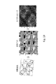
図8〜10は、3つの変調パターンの各々に対する周波数スペクトルを描く。図8は、タイルにおける埋込み位置への疑似ランダムマッピングによるデータ信号の周波数スペクトルを描く。図9は、タイルにおける埋込み位置への密な差分マッピング(例えば、図5から)によるデータ信号の周波数スペクトルを描く。最後に、図10は、タイルにおける埋込み位置への疎な差分マッピング(例えば、図7から)によるデータ信号の周波数スペクトルを図示する。図4〜7のマッピングパターンは、異なるスペクトル特性を有するように拡張及び変更されることができる。 FIGS. 8-10 draw frequency spectra for each of the three modulation patterns. FIG. 8 depicts the frequency spectrum of the data signal by pseudo-random mapping to the embedded position on the tile. FIG. 9 depicts the frequency spectrum of the data signal by dense difference mapping (eg, from FIG. 5) to the embedding position in the tile. Finally, FIG. 10 illustrates the frequency spectrum of the data signal by sparse differential mapping (eg, from FIG. 7) to the embedded position in the tile. The mapping patterns of FIGS. 4-7 can be extended and modified to have different spectral characteristics.
信号パターンを設計する際に、追加の設計考慮事項は、幾何学的不変性の他に被疑信号の小さいブロックからデータを確実に復号することができる能力を含む。概して、補助データを小さいパターンに構成することは、幾何学変換により良い不変性を提供する。追加的に、小さい構成は第2の目的を支持する。
知覚品質のための信号設計
When designing a signal pattern, additional design considerations include the ability to reliably decode data from small blocks of suspected signals in addition to geometric immutability. In general, constructing auxiliary data into smaller patterns provides better invariance for geometric transformations. In addition, the small configuration supports the second purpose.
Signal design for perceptual quality
堅牢性利益に加えて、以上の節で例示した信号パターンは、擬似ランダムマッピング方式などの他の方式を超える知覚品質利益を提供する。画像ベースの信号通信に関しては、人間の目は対角線方向の変調パターンに感応しにくい。したがって、差分変調パターンの対角線的に優位な向きは、人間に目立ちにくい信号通信方式を可能にする。追加的に、利用される信号パターン化は、データ信号が、ホスト画像におけるデータ信号の可視性を低減させるスペクトル特性を有することを可能にする。
同期を容易にする信号設計
In addition to the robustness benefit, the signal patterns illustrated in the above sections provide perceptual quality benefits over other schemes such as the pseudo-random mapping scheme. When it comes to image-based signal communication, the human eye is less sensitive to diagonal modulation patterns. Therefore, the diagonally dominant orientation of the differential modulation pattern enables a signal communication system that is less noticeable to humans. In addition, the signal patterning utilized allows the data signal to have spectral characteristics that reduce the visibility of the data signal in the host image.
Signal design for easy synchronization
上記したように、多くの応用に関して、データチャネルは、データチャネルがその歪みに堅牢であるように設計されることを必要とすることになる歪みに直面するのを予想される。画像の場合、信号通信方式はしばしば、並進、回転及び拡大縮小(scale[スケール])などの幾何学変換に堅牢でなければならない。画像の射影変換は、信号が対象で符号化され、そしてカメラ、スキャナなどで使用される2D画像センサで取り込まれる応用で課題を提示する。2Dセンサアレイが対象から信号を取り込む遠近感を制御することはできず、そのため信号通信方式はある範囲の遠近歪みを扱う必要がある。時間的成分を持つ信号の場合、方式は、音声信号の音高不変の時間スケーリング、並びに他の時間スケーリング及びサンプリング歪みなどの時間的歪みに堅牢でなければならない。 As mentioned above, for many applications, data channels are expected to face distortions that would require the data channels to be designed to be robust to their distortions. For images, signal communication schemes often have to be robust to geometric transformations such as translation, rotation and scaling (scale). Homography of images presents challenges in applications where the signal is object-encoded and captured by a 2D image sensor used in cameras, scanners, and the like. It is not possible to control the perspective that the 2D sensor array captures the signal from the object, so the signal communication scheme needs to handle a range of perspective distortions. For signals with a temporal component, the scheme must be robust to pitch-invariant time scaling of the audio signal, as well as time distortions such as other time scaling and sampling distortions.
同期の必要性は、歪みに本質的に堅牢であるデータ信号通信方式を選択することによって軽減されることができる。例えば、ホストの変調は、幾何学的又は時間的歪み(例えば、空間的又は時間的並進に堅牢なフーリエ振幅係数)に堅牢である領域で行われてもよい。この変調は同期を軽減又は単純化することがある一方で、その変調は、データ容量又は知覚品質の様な信号通信方式の他の能力を制限することがあり得る。結果として、信号通信方式は明示的な同期信号で強化される必要がしばしばあるか、又は黙示的な同期信号を有してもよい。 The need for synchronization can be mitigated by choosing a data signal communication scheme that is inherently robust to distortion. For example, host modulation may be performed in a region that is robust to geometric or temporal distortions (eg, Fourier amplitude coefficients that are robust to spatial or temporal translations). While this modulation may reduce or simplify synchronization, it can limit other capabilities of the signal communication scheme, such as data capacity or perceptual quality. As a result, signal communication schemes often need to be enhanced with explicit sync signals or may have implied sync signals.
明示的及び黙示的な同期信号の例は、我々の前に引用した特許第6,614,914号及び第5,862,260号に提供される。特に、明示的な同期信号の1つの例は、疑似ランダム位相を持ち、被疑信号のフーリエ領域にピークとして現れる一組の正弦波から構成される信号である。例えば、堅牢なデータ信号と併せて同期信号の使用を記載する、第6,614,914号及び第5,862,260号を参照されたい。ここで引用によって援用される米国特許第7,986,807号も参照されたい。 Examples of explicit and implied synchronization signals are provided in Japanese Patent Nos. 6,614,914 and 5,862,260 cited above. In particular, one example of an explicit sync signal is a signal that has a pseudo-random phase and is composed of a set of sine waves that appear as peaks in the Fourier region of the suspected signal. See, for example, Nos. 6,614,914 and 5,862,260, which describe the use of sync signals in conjunction with robust data signals. See also U.S. Pat. No. 7,986,807, which is incorporated herein by reference.
ここで引用によって援用される我々の米国特許出願公開第20120078989号は、この種類の構造を持つ埋込み信号を検出し、そしてこれらの方法から回転、スケール及び並進を復元するための追加方法を提供する。 Our US Patent Application Publication No. 20120078989, incorporated herein by reference, provides additional methods for detecting embedded signals with this type of structure and restoring rotation, scale and translation from these methods. ..
黙示的な同期信号の例及びそれらの使用法は、第6,614,914号及び第5,862,260号の他に、ここで引用によって援用される、第6,625,297号及び第7,072,490号に提供される。 Examples of implied sync signals and their usage are incorporated herein by reference, Nos. 6,625,297 and 5,862,260, as well as Nos. 6,614,914 and 5,862,260. Provided on Nos. 7,072,490.
我々はここで、同期を容易にするように信号を設計する方法の説明に着手する。小領域又は接近して配置される埋込み位置にデータ信号要素を符号化する手法は、我々が同期及びデータ抽出のために利用する利益を有する。デコーダは、被疑信号の小領域の各々からの検出メトリックを累算する。この手法は領域からの判別統計量を累算する。信号要素を符号化するために使用されるこれらの小領域は、幾何学的歪み、ホスト信号干渉及び雑音を含む、空間的に非定常である信号歪みに大領域より感応しにくい。しかしながら、小領域からの判別統計量は、他の領域からの統計量と比較して大きい分散を有する傾向がある。したがって、我々は、幾何学的歪み不変性を維持し且つ統計的精度を向上させるために、検出器が多くの小領域統計量を組み合わせることを可能にする信号構造を設計する。手法は、検出メトリックをサンプリングする柔軟な形状をサポートする。 We now begin to explain how to design the signal to facilitate synchronization. Techniques for encoding data signal elements in subregions or closely placed embedding positions have the benefit we utilize for synchronization and data extraction. The decoder accumulates detection metrics from each of the small regions of the suspect signal. This method accumulates discriminant statistics from the region. These small regions used to encode the signal elements are less sensitive to spatially unsteady signal distortions, including geometric distortion, host signal interference and noise. However, the discriminant statistic from the small region tends to have a large variance compared to the statistic from the other region. Therefore, we design a signal structure that allows the detector to combine many subregional statistics in order to maintain geometric distortion invariance and improve statistical accuracy. The technique supports flexible geometry for sampling detection metrics.
我々は、我々の同期手法の説明を信号設計の第1の実施形態で始める。図11は、疎な差分パターンを描く。文字「a」は、符号化されている補助信号のデータ信号要素に対応する。より詳細に説明することになるように、同期手法は、黙示的な同期信号(自己同期とも称される)、明示的な同期信号、又は両方の組合せを利用することができる。黙示的な同期信号は、例えば、要素「a」などの可変データ搬送要素のパターンによって形成される信号である。明示的な同期信号は、要素の複合パターンの何らかの部分を固定信号専用にすることによって選択されてもよい。 We begin the description of our synchronization method with the first embodiment of signal design. FIG. 11 draws a sparse difference pattern. The letter "a" corresponds to the data signal element of the encoded auxiliary signal. As will be described in more detail, synchronization techniques can utilize implicit synchronization signals (also referred to as self-synchronization), explicit synchronization signals, or a combination of both. The implied synchronization signal is, for example, a signal formed by a pattern of variable data carrying elements such as the element "a". The explicit sync signal may be selected by dedicating some part of the compound pattern of the elements to a fixed signal.
図6のパターンと比較して、図11のパターンはより大きく、データ要素「a」の符号化を4×4領域にわたる8つの埋込み位置の配置に拡張している。我々は、より固有の且つ認識できるパターンを提供するためにこの構造を選んだ。 Compared to the pattern of FIG. 6, the pattern of FIG. 11 is larger and extends the coding of the data element "a" to the arrangement of eight embedding positions over a 4x4 region. We chose this structure to provide a more unique and recognizable pattern.
図12は、埋込み位置にマッピングされる追加データ信号要素を図示するために拡張される、図11の疎なパターンを描く。データ信号要素が1つのメッセージシンボル又はビットに対応する場合には、例えば、図12は、5×8領域の埋込み位置への8ビットのマッピングを例示する。このパターンは、異なるメッセージシンボルに割り当てられる埋込み位置をインターリーブすることによって全ての利用できる埋込み位置を使用する。 FIG. 12 depicts the sparse pattern of FIG. 11 extended to illustrate additional data signal elements that are mapped to embedded locations. When the data signal element corresponds to one message symbol or bit, for example, FIG. 12 illustrates an 8-bit mapping to an embedded position in a 5x8 region. This pattern uses all available embedding positions by interleaving the embedding positions assigned to different message symbols.
パターンの差分配置を利用するために、デコーダは、パターンの差分関係からデータ要素の推定値を抽出するように構成されるフィルタを利用する。フィルタは、各データ要素を符号化している信号間の差分関係を活用することによって、雑音に対するデータ信号の信号対雑音比を増加させる。図13は、この配置にデータ信号要素「a」に関する8つの差分関係があることを例示する。フィルタは、8つの比較を利用してデータ信号の推定値を予測又は再構築する。このフィルタは、同期処理の他にデータ抽出処理にも利用されてもよい。フィルタの形状は、フィルタが信号値をサンプリングする範囲、及び差分関係を活用するためにフィルタが評価する埋込み位置の位置関係に対応する。例えば、フィルタは、差分対における信号値の比較を組み合わせて、ホスト内容を低減させ且つデータ信号を増加させるように設計されてもよい。後に、我々は、様々なフィルタの形態並びにフィルタを表現及び実装する方法を更に詳述する。 To take advantage of the difference arrangement of patterns, the decoder utilizes a filter configured to extract estimates of data elements from the difference relationships of the patterns. The filter increases the signal-to-noise ratio of the data signal to noise by taking advantage of the difference relationship between the signals encoding each data element. FIG. 13 illustrates that this arrangement has eight differential relationships with respect to the data signal element “a”. The filter uses eight comparisons to predict or reconstruct estimates of the data signal. This filter may be used not only for synchronous processing but also for data extraction processing. The shape of the filter corresponds to the range in which the filter samples the signal value and the positional relationship of the embedding position evaluated by the filter in order to utilize the difference relationship. For example, the filter may be designed to reduce host content and increase the data signal by combining the comparison of signal values in the difference pair. Later, we will further elaborate on the various forms of the filter and how the filters are represented and implemented.
図14は、図11〜12の信号配置の信号スペクトルを例示する。図15は、信号スペクトルへの閾値演算を描き、そして図16は、埋込み後のスペクトルを図示する。これらの図は、検出器が判別することができ、様々な検出方式を使用して同期を容易にする構造をスペクトルが有することを図示する。我々は、我々の特許文献から援用するものに加えて、幾つか注目することになる。 FIG. 14 illustrates the signal spectrum of the signal arrangement of FIGS. 11-12. FIG. 15 depicts a threshold calculation on the signal spectrum, and FIG. 16 illustrates the spectrum after embedding. These figures illustrate that the spectrum has a structure that can be discriminated by the detector and facilitates synchronization using various detection methods. We will note some in addition to those incorporated from our patent literature.
図17は、図11の配置を使用して符号化される信号を復号する方法を例示するフロー図である。処理モジュール700では、方法は、この場合には回転及びスケールを含む、初期変換パラメータを近似することによって開始する。このモジュールは、被疑信号を検出のために準備するために被疑信号への前処理演算を含む。これらの演算は、データ信号が符号化されている領域に信号を変換すること、並びに信号をフィルタリングしてホスト及び他の雑音との干渉を低減させることを含む。例えば、データチャネルが特定の解像度及び周波数範囲で1つ又は複数の特定の色チャネルに符号化されていれば、モジュール700はそのチャネルに信号を変換する。この演算は、雑音及びチャネル外のホスト信号内容を除去するために1つ又は複数のフィルタリング段階を含んでもよい。
FIG. 17 is a flow diagram illustrating a method of decoding a coded signal using the arrangement of FIG. In the
モジュール700は、パターン認識方法を活用して符号化信号構造の初期回転及びスケールパラメータを近似する。図14〜16に例示したように、符号化信号構造は、信号スペクトルのテンプレートを形成する配置を有する。被疑信号のこのテンプレートの回転及びスケールを近似するために利用されてもよい各種のパターンマッチング方法がある。図18は、テンプレート(「信号」と標記される)及び被疑信号のフィルタ処理されたスペクトル(「測定」と標記される)がログポーラ(LP)座標系に変換され、そして相関される1つの種別のそのような方法を例示する。LP座標系内の相関の最大相関ピークが突き止められる。このピークの位置は、テンプレートの近似回転及びスケールに対応する。
画像信号通信のための一実施形態において、モジュール700は以下を利用する。
In one embodiment for image signal communication, the
1.符号化データ信号を保持しつつ画像内容を除去する双方向及びガウスフィルタ、 1. 1. Bidirectional and Gaussian filters that remove image content while retaining the encoded data signal,
2.空間周波数を推定するグレースケール変換、平均値減算及び2D FFT、 2. Grayscale transform to estimate spatial frequency, mean subtraction and 2D FFT,
3.2Dずれを回転及びスケールと等しくする振幅及びログポーラ変換、並びに Amplitude and log polar transformations that make 3.2D deviation equal to rotation and scale, and
4.処理アーチファクト及び雑音を除去する振幅クリッピング及びガウスフィルタ。 4. Amplitude clipping and Gaussian filters that remove processing artifacts and noise.
図17に戻ると、信号抽出モジュール702は、回転及びスケールを補償する初期回転及びスケール推定値を使用して補助データ信号の近似値を抽出する。モジュール702は、演算子(例えば、補間器)をサンプリングして、初期の回転及びスケールによって修正される、被疑信号内の埋込み位置をサンプリングすることを含む。モジュール702は、上記したように信号要素を符号化するために使用される差分関係を利用してデータ信号の推定値を再構築する抽出フィルタも含む。図19は、初期回転及びスケールで適用されるフィルタパターン(「回転抽出」)の例、再構築されるデータ信号、及びデータ信号のスペクトルを描く。以下に、我々は、特定の差分配置のために設計される抽出フィルタの動作をより詳細に説明する。
Returning to FIG. 17, the
モジュール704は、再構築されたデータ信号にアクセスし、そしてデータ信号をテンプレートに合わせる精密化回転及びスケールパラメータを決定する。モジュール704は、データ信号の再構築された推定値からスペクトルを計算する。例示のために、図19は、近似化データ信号の例及びその信号のスペクトルを図示する。このスペクトルから、モジュール702は回転及びスケールのより正確な推定値を得る。特に、再構築されたデータ信号におけるスペクトルピークの位置は、スペクトルピークをテンプレートに合わせる幾何学変換を決定することによって回転及びスケールを決定するために使用される。この処理のために、上記のログポーラ方法、及び/又は前に引用した第20120078989号の最小2乗手法を含め、各種のパターンマッチング技法が使用されてもよい。
データを抽出する前に、第20120078989号及び第6,614,914号に記載されるように、被疑信号におけるタイルの並進の推定値を決定するために、追加の精密化モジュールが含まれてもよい。並進は、被疑信号のタイル内の埋込み位置の座標(例えば、タイルの始まりに対してタイルの始まり及びビットセルの位置)を提供する。並進を復元するために、オーバーサンプリングも使用されてもよい。 Prior to extracting the data, additional refinement modules may be included to determine tile translation estimates at the suspect signal, as described in 20120078989 and 6,614,914. Good. Translation provides the coordinates of the embedding position within the tile of the suspect signal (eg, the tile start and the bit cell position relative to the tile start). Oversampling may also be used to restore translation.
データ抽出モジュール706はここで、精密化幾何学変換パラメータ(精密化回転、スケール及び並進)に基づいてサンプリングされる、タイル内の埋込み位置からデータ系列を抽出する。データ系列抽出は抽出フィルタを適用し、前の通り差分符号化関係を再び利用するが、今回は埋込み位置のより正確な判定を伴う。
The
図20は、2D配列の埋込み位置におけるデータ系列のスパイラル符号化を例示する。この種類の符号化は、ID系列が任意の開始位置から抽出されることを可能にする。位置合わせモジュール708は次いで、系列の始まりを決定する。ID系列を位置合わせするための各種の技法がある。1つの手法は、データ系列の始まりを指定するID系列における固定ビットパターンを使用することである。別の手法は、系列に復号演算を適用し、そして桁送りして繰り返すことであり、毎回誤りのない系列が検出されるまで、記号列における誤り検出ビットを計算及び検査する。
FIG. 20 illustrates spiral coding of a data series at the embedding position of a 2D array. This type of coding allows the ID sequence to be extracted from any starting position. The
系列復号モジュール710は、データ符号化プロトコルに従って、図3のデータ発生器の逆演算を適用する。プロトコルに応じて、この逆演算は、搬送波信号(使用される場合)からビットを復調すること、及び/又はビットセルに対する反復符号化からの推定値を組み合わせて、誤り訂正符号化シンボルのソフト推定値を計算することを含んでもよい。これらのソフト推定値は次いで誤り訂正復号される(例えば、畳込み符号化メッセージのビタビ復号)。復号されたビットは次いで誤りに関して検査される(例えば、固定ビットが正しい系列を有することを確認する、及び/又は誤り検出ビットを計算し、そして誤り検出ビットを符号化誤り検出ビットと比較する)。
The
図6から図11への経過で最初に描いたように、データ要素を表現するビットセルのパターンを繰り返すことは時には有益である。図21〜23は、ビットセル配置の例及び相関性質を例示して反復の利点を強調する。我々はビットセルパターンの反復を「タイリング」と時には称し、その理由は、タイリングが、埋込み領域の座標系における少なくとも1つの次元に沿って互いに隣接した基本ブロックの反復を暗示するからである。タイリングの利益は、少なくとも2、3の方法で明らかにされている。1つの利益は、ビットセルパターンの反復が、様々なパターン検出方法を使用して検出されることができる黙示的な構造を作成することである。例えば、構造は、フーリエ領域、自己相関領域又は何らかの他の変換領域でテンプレートを形成してもよい。別の利益は、反復が相関検出器の効率を上昇させることができることであり、このことを我々は図21〜23に例示することになる。最後に、特定の応用内のタイリングの効用は、知覚品質、及び検出器の効率、ホスト信号干渉を軽減すること、及びデータ信号の判別を容易にすることを含め、前に概説した設計考慮事項によって要求される。 It is sometimes beneficial to repeat the bit cell pattern that represents the data element, as first drawn in the process from FIG. 6 to FIG. Figures 21-23 illustrate the benefits of iteration by exemplifying examples of bit cell placement and correlation properties. We sometimes refer to the repetition of bit cell patterns as "tiling" because tiling implies the repetition of basic blocks adjacent to each other along at least one dimension in the coordinate system of the embedded region. The benefits of tiling are manifested in at least a few ways. One benefit is to create an implied structure in which bit cell pattern iterations can be detected using a variety of pattern detection methods. For example, the structure may form a template in a Fourier region, an autocorrelation region, or some other transform region. Another benefit is that iterations can increase the efficiency of the correlation detector, which we will illustrate in Figures 21-23. Finally, the utility of tiling within a particular application includes the design considerations outlined above, including perceived quality and detector efficiency, mitigating host signal interference, and facilitating data signal discrimination. Required by matter.
図21の左側は、各々4つのメッセージ要素を符号化する2つの4×4タイルを並べて例示する。第1の4×4タイルはメッセージ要素A、B、C及びDを符号化する。第2の4×4タイルはメッセージ要素E、F、G及びHを符号化する。両4×4タイルとも図7の差分方式を利用する。図21の右側は、信号のFFTをとることによって計算される、タイルのスペクトルを描く。 The left side of FIG. 21 illustrates side by side two 4x4 tiles, each encoding four message elements. The first 4x4 tile encodes the message elements A, B, C and D. The second 4x4 tile encodes the message elements E, F, G and H. Both 4x4 tiles use the difference method shown in FIG. The right side of FIG. 21 depicts the spectrum of tiles calculated by taking the FFT of the signal.
差分符号化をホスト抑制のために利用するために、デコーダは、各メッセージ要素に対する差分符号化されたビットセルを比較するフィルタを利用する。このフィルタは、検出、同期及びメッセージ抽出演算のために利用されてもよい。フィルタ演算は、図6の左上3×3ビットセルのパターンを有する信号が埋込み領域に変換された後に、その信号を被疑信号で畳み込むことによって実装されてもよい。このフィルタは、

として表されてもよい。
In order to utilize the differential coding for host suppression, the decoder utilizes a filter that compares the differentially encoded bit cells for each message element. This filter may be utilized for detection, synchronization and message extraction operations. The filter operation may be implemented by convolving the signal with the suspected signal after the signal having the pattern of the upper left 3 × 3 bit cell of FIG. 6 is converted into the embedded region. This filter
It may be expressed as.
例示のためにデコーダがデータ信号と位置合わせされると仮定すると、このフィルタをこの信号で畳み込む処理は、3×3フィルタ中心が2つのタイル内の丸付き位置に位置付けられるときに有効な相関をもたらすことになる。有効な相関は、3×3フィルタパターンがデータ要素(タイル1内のA、B、C又はD、及びタイル2内のE、F、G又はH)のための3×3パターンのビットセルの位置と一致する場合である。フィルタが各4×4タイルの境界でビットセルに位置付けられると、フィルタは異なるメッセージ要素をサンプリングし、無効な相関をもたらす。したがって、図21の配置では、タイル当たり16のうち4つの有効な相関を持つ埋込み位置がある。このフィルタの出力は、検出及び同期を容易にするためにタイル全体にわたって、及び各メッセージ要素の値の証拠を集計するためにメッセージ要素の位置にわたって、集計されてもよい検出メトリック(例えば、相関の測度)を提供する。
Assuming that the decoder is aligned with the data signal for illustration purposes, the process of convolving this filter with this signal provides a valid correlation when the 3x3 filter center is positioned at the circled position within the two tiles. Will bring. A valid correlation is that the 3x3 filter pattern is the position of the 3x3 pattern bit cells for the data elements (A, B, C or D in
図22は、4つのメッセージ要素A、B、C及びDが8×8タイルにわたって繰り返されること以外は、図21と同様である。図22における各要素の反復は、図21と比較して2倍になった。FFTで計算される、対応するスペクトルは図22の右側に図示される。この倍加は、堅牢性及び判別を上昇させるが、データ容量を減少させる。同じ3×3フィルタで畳み込まれると、64のうちの36の有効な相関を持つ埋込み位置がある。 FIG. 22 is similar to FIG. 21 except that the four message elements A, B, C and D are repeated over 8 × 8 tiles. The iteration of each element in FIG. 22 was doubled compared to FIG. The corresponding spectrum calculated by FFT is shown on the right side of FIG. This doubling increases robustness and discrimination, but reduces data capacity. When folded with the same 3x3 filter, there are 36 of 64 embedded positions with a valid correlation.
非相関タイル境界は、低相関線の格子の形成に基づいて同期のために使用されることができる。この格子の線は、本明細書に記載されるパターン検出方法を使用してタイルの位置合わせを判定するために使用されてもよいテンプレートを形成する。 Uncorrelated tile boundaries can be used for synchronization based on the formation of a grid of low correlation lines. The lines of this grid form a template that may be used to determine tile alignment using the pattern detection methods described herein.
図23は、タイル内のパターン配置の別の例を図示して、多くの他の可能なビットセルパターン及びタイリング配置があるという点を例示する。各メッセージ要素A、B、C又はDのためのビットセルパターンは、異なる配置でインターリーブ及び配向されてもよく、及び異なる率で繰り返されてもよい。メッセージ要素の幾つかは、メッセージ要素が非相関境界を生成しないようにタイル境界にわたって繰り返されてもよい。 FIG. 23 illustrates another example of pattern placement within a tile, exemplifying that there are many other possible bit cell patterns and tiling arrangements. The bit cell patterns for each message element A, B, C or D may be interleaved and oriented in different arrangements and may be repeated at different rates. Some of the message elements may be repeated across tile boundaries so that the message elements do not create uncorrelated boundaries.
差分配置の数例及びデコーダにおいて差分配置を利用するフィルタを例示したが、我々はここで、デコーダ演算を更に探究する。図4及び6の信号パターンは差分信号カーネルに対応する。図4は密な差分カーネルを描き、そして図4と比較して、図6は疎な差分カーネルを描く。これらの2×2及び3×3信号カーネルは、データが専らタイル内の局所レベルで復元される場合、雑音及び偽陽性相関に影響されやすい。デコーダは、多くの小領域統計量からの情報を組み合わせて、タイルより大きい被疑信号のより大きい部分に対する合成信号メトリックを得ることによって、信号回復の堅牢性を向上させる。 Having illustrated some examples of delta placement and filters that utilize delta placement in decoders, we now explore the decoder operation further. The signal patterns in FIGS. 4 and 6 correspond to the differential signal kernel. FIG. 4 depicts a dense delta kernel, and compared to FIG. 4, FIG. 6 depicts a sparse delta kernel. These 2x2 and 3x3 signal kernels are susceptible to noise and false positive correlations when the data is restored exclusively at the local level within the tile. The decoder improves signal recovery robustness by combining information from many subregional statistics to obtain a composite signal metric for the larger portion of the suspect signal that is larger than the tile.
我々は、受信器動作特性(ROC)を測定することによって我々の信号通信システムの効果を調査した。図24は、固定及び可変ビット信号通信方式に対する二組のROC曲線プロットを、一方を−10dBの信号対雑音比(SNR)で且つ他方を−30dBのSNRで例示する。ROC曲線は、多様な信号通信システムの性能を比較するために頻繁に使用される。ROC曲線は、信号と雑音との間を区別することができる能力を示す特定の受信器の真及び偽陽性検出トレードオフを図示する。ROC曲線が左及び上軸に近い程、受信器は信号と雑音との間をより十分に区別することができる。対角ROC曲線(線)は、受信器が信号と雑音を区別することができないことを示す。いかなるシステムでも、雑音の強度が増加するにつれて、我々はROC曲線が対角線により近く移動するのを予期する。 We investigated the effectiveness of our signal communication system by measuring the receiver operating characteristic (ROC). FIG. 24 illustrates two sets of ROC curve plots for fixed and variable bit signal communication schemes, one with a signal-to-noise ratio (SNR) of -10 dB and the other with an SNR of -30 dB. ROC curves are often used to compare the performance of various signal communication systems. The ROC curve illustrates the true and false positive detection trade-offs for a particular receiver that show the ability to distinguish between signal and noise. The closer the ROC curve is to the left and upper axes, the better the receiver can distinguish between signal and noise. Diagonal ROC curves (lines) indicate that the receiver is unable to distinguish between signal and noise. In any system, as the noise intensity increases, we expect the ROC curve to move closer diagonally.
我々はここで、自己同期差分(SSD)方法のROC特性を固定信号同期方法と比較することに興味がある。我々は、全てのビットが独立して変化するようにされる場合、最高で4096/4=1024ビットを搬送することができる64×64ビットセル範囲にわたるSSDペイロードから始める。我々は、未知のビットを持つSSDタイルを全てのビットが既知であるSSDタイルと比較する。この比較は、既知のデータが受信器での信号回復にどれくらい影響を与えるかを我々に示すことになる。我々は実験ではカバー信号(例えば、カバー画像)を使用せず、そして受信器は雑音によって損なわれる純データタイルを処理する。 We are now interested in comparing the ROC characteristics of the self-synchronous difference (SSD) method with the fixed signal synchronization method. We start with an SSD payload that spans a 64 x 64 bit cell range that can carry up to 409 6/4 = 1024 bits if all bits are allowed to change independently. We compare SSD tiles with unknown bits to SSD tiles with all known bits. This comparison will show us how much known data affects signal recovery at the receiver. We do not use cover signals (eg, cover images) in our experiments, and the receiver processes pure data tiles that are compromised by noise.
可変ビットSSD透かしに対して、受信器は、雑音の多い信号ブロックを以下の差分カーネル
で畳み込む。
For variable bit SSD watermark, the receiver has the following differential kernel with noisy signal blocks
Fold in.
ここで、d1は、データを埋め込むために使用される差分カーネルである。受信器は次いで、以下の通り各埋込み可変ビットで2値相関ciを計算し、
![]()
Here, d 1 is a differential kernel used for embedding data. Receiver then computes a binary correlation c i at each embedded variable bit as follows,
![]()
ここで、aiは2値ペイロードビットbiに対応する被疑信号ブロックであり、そして我々は、
![]()
シンボルを使用して畳込み演算を表現した。信号メトリックは、個々のビット相関を合計することによって得られる全体のブロック相関である。
Here, a i is a suspect signal block corresponding to the binary payload bits b i, and we,
![]()
The convolution operation was expressed using symbols. The signal metric is the total block correlation obtained by summing the individual bit correlations.
第2の差分カーネルd2は、被疑信号をフィルタリングして、チャネルにおける雑音(カバー信号からの潜在的干渉を含む)に対する可変信号の抽出を向上させる追加手段を提供するためのただ1つのオプションを表現する。 The second differential kernel d 2 has only one option to filter the alleged signal and provide additional means to improve the extraction of variable signals for noise (including potential interference from the cover signal) in the channel. Express.
固定/既知データビットbiの場合には、受信器は、以下の通り個々の相関を計算し、
![]()
In the case of fixed / known data bit b i, the receiver calculates the streets individual correlations below,
![]()
そして信号メトリックは、これらの個々のビット相関を合計することによって得られる。 The signal metric is then obtained by summing these individual bit correlations.
図24は、まさに記載した受信器実装のための可変及び固定ビットSSD方法に対するROC曲線を、左に−10dB及び右に−30dBの2つの異なるSNRレベルで図示する。図24は、両プロットにおいて信号と雑音との間の判別無しの限定する場合も対角線によって図示する。左プロットの固定ビットSSD ROC曲線は、同曲線がy軸と一致するので見にくいが、−10dBで信号と雑音との間の完全な判別を示す。右プロットで、可変ビットSSD信号通信方法は対角ROC線と略一致するが、−30dBで信号と雑音との間の判別無しを示す。左プロットの−10dB SNRで、可変ビットSSD方法に対するROC曲線は、右プロットに図示される−30dBでの固定ビットSSD方法に対するROC曲線に一致する。この一致は、固定ビットSSDが可変ビットSSD方法の20dB下の雑音レベルで検出されることができることを示す。このレベル差は堅牢性の大きな差のように見えるかもしれないが、この比較は、デコーダがデータ信号と同期されている場合に限定される。
FIG. 24 illustrates the ROC curves for the variable and constant bit SSD methods just described for receiver mounting at two different SNR levels: -10 dB to the left and -30 dB to the right. FIG. 24 is shown diagonally with no distinction between signal and noise in both plots. The constant bit SSD ROC curve in the left plot is difficult to see because it coincides with the y-axis, but at -10 dB it shows a complete distinction between signal and noise. In the right plot, the variable bit SSD signal communication method is approximately the same as the diagonal ROC line, but at -30 dB there is no distinction between signal and noise. The ROC curve for the variable bit SSD method at -10 dB SNR in the left plot matches the ROC curve for the constant bit SSD method at -30 dB shown in the right plot. This match indicates that the constant bit SSD can be detected at a
実際には、デコーダは、まずデータ信号を同期させる、例えば、メッセージ信号抽出に加えて位置合わせパラメータ(例えば、画像のための幾何学変換パラメータ)を決定しなければならない。これらの追加要因が固定及び可変SSD信号通信方法間の堅牢性差を低減させることがあることがあり得る。また、更なる調査がSSD信号のためのより良い信号回復方法を見出してもよく、そのような方法は信号のROC特性を向上させる。 In practice, the decoder must first synchronize the data signals, eg, in addition to message signal extraction, to determine alignment parameters (eg, geometric transformation parameters for the image). These additional factors may reduce the robustness difference between fixed and variable SSD signal communication methods. Further investigation may also find better signal recovery methods for SSD signals, such methods improving the ROC characteristics of the signal.
以上、我々は、埋込み位置の変換を決定するための様々な同期方法を説明した。ここで、我々は追加種別の方法を説明する。埋込みSSDパターンの回転バージョンである2値パターンを使用してホスト信号干渉を推定する方法は、同じパターンの更なる回転及びスケールバージョンを含むように拡張されることができる。そのような手法では、デコーダは、被疑画像にこれらのフィルタの対を適用してベクトル信号メトリック又は特徴ベクトルを生成することから、信号メトリックを計算する。これらの特徴ベクトルは、ランダムに選ばれる純データタイルの様々な回転及びスケールに対して計算される。特徴ベクトルはデータの統計的特性を追跡するので、特徴ベクトルは非常に安定しており且つ選ばれたデータタイルから独立している。 So far, we have described various synchronization methods for determining the transformation of the embedding position. Here, we describe an additional type of method. The method of estimating host signal interference using a binary pattern, which is a rotated version of the embedded SSD pattern, can be extended to include a further rotated and scaled version of the same pattern. In such a technique, the decoder calculates the signal metric by applying a pair of these filters to the suspected image to generate a vector signal metric or feature vector. These feature vectors are calculated for various rotations and scales of randomly chosen pure data tiles. Since the feature vector tracks the statistical properties of the data, the feature vector is very stable and independent of the selected data tile.
この方法の改良は、ランダムデータタイルの複数のサンプルにわたる平均化特徴ベクトルを計算することである。次いで、未知の回転及びスケールを持つ埋込み画像に対して、デコーダは、特徴ベクトルを計算し、そしてその特徴ベクトルを予め計算された特徴ベクトルのリストに対して相関させる。最大相関を持つベクトルに対応する回転及びスケールが、画像変換のための推定値を提供する。 An improvement in this method is to calculate an averaged feature vector across multiple samples of random data tiles. For embedded images with unknown rotations and scales, the decoder then computes the feature vectors and correlates the feature vectors with a pre-computed list of feature vectors. The rotations and scales corresponding to the most correlated vectors provide estimates for image transformation.
特徴ベクトル計算に使用されるテンプレートの例は以下の通りである。
An example of a template used for feature vector calculation is as follows.
この例示では、12の相関パターンがあり、メトリック計算でこれら相関パターンの対を選んだ結果は、
の一対メトリックとなり、こうして特徴ベクトルは、画像のあらゆる回転及びスケールに対応する66のパラメータを有する。回転及びスケールパラメータが変化するにつれて、特徴ベクトルパラメータが平滑に変化すると認められるので、パラメータ空間の離散サンプリングは、デコーダがサンプリング格子間にあるパラメータを推定することを可能にする。
In this example, there are 12 correlation patterns, and the result of selecting a pair of these correlation patterns in the metric calculation is
The feature vector thus has 66 parameters corresponding to any rotation and scale of the image. Discrete sampling in the parameter space allows the decoder to estimate the parameters between the sampling grids, as the feature vector parameters are found to change smoothly as the rotation and scale parameters change.
回転及びスケールパラメータを識別する際の特徴ベクトルの効果を測定するために、我々は特徴ベクトルの混同行列を計算するが、混同行列は異なる回転及びスケールでの特徴ベクトル間の相関である。混同行列が略対角であれば、このことは、特徴ベクトルが無相関であり、そして回転及びスケールパラメータを正確に推定するために使用されてもよいことを意味する。混同行列が略均等な値であれば、このことは、特徴ベクトルが高相関され、そして一対の回転及びスケールパラメータを別の対から区別することができないことを意味する。 To measure the effect of feature vectors in identifying rotation and scale parameters, we calculate the confusion matrix of feature vectors, which is the correlation between feature vectors at different rotations and scales. If the confusion matrix is approximately diagonal, this means that the feature vectors are uncorrelated and may be used to accurately estimate rotation and scale parameters. If the confusion matrix has approximately equal values, this means that the feature vectors are highly correlated and the pair of rotation and scale parameters cannot be distinguished from the other pair.
我々は、マトラボ(Matlab)ベクトル表記法で、0:10:90度の回転ステップ及び0.5:0.1:1.5のスケールステップにわたってデータタイルを掃引した。各特徴ベクトルは、ゼロ平均及び単位分散を有するように正規化された。全部で、我々は各々長さ66の110の特徴ベクトルを得た。混同行列は、正方配列に配置される全ての対の特徴ベクトルをたすき掛けすることによって得られる。この行列の対角線上の相関値は行列で最高値であり、且つ相関値自体との各特徴ベクトルの相関を表し、且つ正規化のため1に等しくなければならない。我々は、計算した特徴ベクトルを持つ混同行列が略対角であり、且つ埋込みパターンが90度回転対称を有したために予想されるように、90度間隔であった相関ベクトルが高相関されたことを見出した。 We swept the data tiles over a rotation step of 0:10:90 degrees and a scale step of 0.5: 0.1: 1.5 in Matlab vector notation. Each feature vector was normalized to have zero mean and unit variance. In total, we obtained 110 feature vectors, each of length 66. The confusion matrix is obtained by multiplying the feature vectors of all pairs arranged in a square array. The diagonal correlation value of this matrix must be the highest in the matrix, represent the correlation of each feature vector with the correlation value itself, and be equal to 1 for normalization. We found that the correlation vectors that were 90 degree apart were highly correlated, as would be expected because the confusion matrix with the calculated feature vectors was approximately diagonal and the embedded pattern had 90 degree rotational symmetry. I found.
我々は、純データ信号から得られる混同行列をホスト画像に埋め込まれたデータ信号に対して得られる混同行列と比較した。我々は、オクタクシス(octaxis)と呼ばれる予測フィルタを適用してホスト信号干渉を抑制し、そして同じスケール及び回転を通じて掃引する前に特徴ベクトルを計算した。更に予測フィルタについては、ここで引用によって援用される、我々の米国特許第7,076,082号及び第8,687,839号を参照されたい。混同行列は、純データタイルで得られる行列と同様である。このことは、純データタイルに対して計算される特徴ベクトルが、画像などのカバー信号に埋め込まれるデータ信号の回転及びスケールパラメータを推定するために使用されてもよいことを示唆する。 We compared the confusion matrix obtained from the pure data signal with the confusion matrix obtained from the data signal embedded in the host image. We applied a predictive filter called octaxis to suppress host signal interference and calculated feature vectors before sweeping through the same scale and rotation. Further for predictive filters, see our US Pat. Nos. 7,076,082 and 8,687,839, incorporated herein by reference. The confusion matrix is similar to the matrix obtained with pure data tiles. This suggests that the feature vector calculated for the pure data tile may be used to estimate the rotation and scale parameters of the data signal embedded in the cover signal such as an image.
我々は、疎な差分メッセージペイロードが埋め込まれる画像のスキャンでこの方法を試験した。我々の試験は、特徴ベースの方法が疎な差分ペイロードのみに基づいて変換を復元することができ、且つ別個の同期信号を必要としないことを示した。
直交差分パターン
We tested this method by scanning images with embedded sparse differential message payloads. Our tests have shown that feature-based methods can restore transformations based only on sparse differential payloads and do not require a separate sync signal.
Orthogonal difference pattern
以上に実証したように、透かし信号を埋め込みつつ、平滑度及び通例出現するカバー信号特徴(例えば、画像内容内の線及び縁又は音声の時間的に隣接したフレームの周波数スペクトルなどの)を利用することは有益である。我々の信号抽出フィルタは、この手法を使用してホスト信号変動を相殺/抑制する。1つのそのようなフィルタは、上記したように、オクタクシスフィルタである。オクタクシスは、ビットセルを8つの近傍と比較して比較値(例えば、正の差に対して+1、−1又は負の差)を提供し、そして比較値を合計する。異なる近傍の配置及び重みが、異なる機能に従ってフィルタを成形するために適用されてもよい。別の1つは十字フィルタであり、本明細書に前に援用した米国特許第6,614,914号に記載されるように、着目したサンプルが水平近傍及び垂直近傍の平均と比較される。 As demonstrated above, while embedding the watermark signal, it utilizes smoothness and commonly appearing cover signal features (eg, frequency spectra of lines and edges in the image content or temporally adjacent frames of audio). That is beneficial. Our signal extraction filter uses this technique to offset / suppress host signal fluctuations. One such filter is an octaxis filter, as described above. Octaxis provides a comparison value (eg, +1, -1 or negative difference to a positive difference) by comparing the bit cell with eight neighborhoods, and sums the comparison values. Different neighborhood arrangements and weights may be applied to shape the filter according to different functions. Another is a cross filter, in which the sample of interest is compared to the average of the horizontal and vertical neighborhoods, as described in US Pat. No. 6,614,914, which was previously incorporated herein.
データ信号が差分埋め込みされると、フィルタ出力は更に強調される。 The filter output is further emphasized when the data signal is differentially embedded.
差分変調のための基本カーネルは、図4で導入される2×2行列である。
The basic kernel for differential modulation is the 2x2 matrix introduced in FIG.
しかしながら、このカーネルはぼやけ及びサンプリングオフセットに影響されやすい。図6で導入されるように、カーネルの拡張バージョンが実際にはより適することがある。
However, this kernel is susceptible to blurring and sampling offsets. An extended version of the kernel may actually be more suitable, as introduced in FIG.
これらのカーネルは、文字の各々が各カーネルによって埋め込まれるデータを表す、図7に図示される非重複様式でタイルビットセルに使用されてもよい。エンコーダは、チャネルの埋込み領域における16の埋込み位置毎に4つのメッセージ要素(A、B、C、D)を埋め込む。この様式は、メッセージ要素をビットとして、4/16=.25ビット/埋込み位置の埋込み効率を我々に与える。 These kernels may be used for tile bit cells in the non-overlapping format illustrated in FIG. 7, where each character represents the data embedded by each kernel. The encoder embeds four message elements (A, B, C, D) for every 16 embedding positions in the embedding area of the channel. In this format, the message element is a bit, and 4/16 =. It gives us the embedding efficiency of 25 bits / embedding position.
我々が差分埋込みパターン間の重複を許容すれば、埋込み効率は向上されることができる。例えば、2つのゼロ平均直交ベクトルの積によって生成される差分埋込みパターンを考える。
我々は、
を得ることになる。
Embedding efficiency can be improved if we allow duplication between differential embedding patterns. For example, consider a differential embedding pattern generated by the product of two zero mean orthogonal vectors.
we,
Will get.
uuTのための行列が我々が先に導入したのと同じ差分カーネルであることに留意されたい。我々は次いで、以下の通り3×3配置の埋込み位置に4つのビットA、B、C、Dを埋め込んでもよい。
X=AuuT+BuvT+CvuT+DvvT
Note that the matrix for uu T is the same delta kernel we introduced earlier. We may then embed the four bits A, B, C, D at the embedding positions in the 3x3 arrangement as follows.
X = Au T + Buv T + Cv T + Dvv T
この埋込みは、9つの埋込み位置のうち4=0.44ビット/埋込み位置の埋込み効率をもたらす。個々のデータを抽出するために、デコーダは、2つの基底ベクトルuTv=0の直交性質を使用する。例えば、ビットBを抽出するために、デコーダは、そのビットを符号化するために使用される埋込みベクトルに基づいて抽出フィルタを適用する。フィルタ演算は、uTXv=BuTuvTv=B||u||2||v||2、したがってB=uTXv/||u||2||v||2として表されてもよい。同様に、A=uTXu/||u||4など。 This embedding provides an embedding efficiency of 4 = 0.44 bits / embedding position out of 9 embedding positions. To extract the individual data, the decoder uses the orthogonal nature of the two basis vectors u T v = 0. For example, to extract bit B, the decoder applies an extraction filter based on the embedded vector used to encode that bit. The filter operation is expressed as u T Xv = Bu T uv T v = B || u || 2 || v || 2 , and therefore B = u T Xv / || u || 2 || v || 2. You may. Similarly, A = u T Xu / || u || 4, etc.
差分埋込みでは、エンコーダは、埋込み位置でのホスト信号値(例えば、画像の画素値、画像、音声又は映像の変換領域係数など)の一対差にデータ要素を埋め込む。ベクトルu及びvがゼロ平均であるので、データを抽出することは、いかなる平滑なホスト信号変動もゼロにする。したがって、我々は、この埋込み処理を、一対差分埋込みの汎化として見てもよい。 In differential embedding, the encoder embeds data elements in a pair of host signal values at the embedding position (eg, image pixel values, image, audio, or video conversion region coefficients, etc.). Since the vectors u and v are zero averages, extracting the data zeros any smooth host signal variation. Therefore, we may view this embedding process as a generalization of paired difference embedding.
埋込みベクトルu及びvの1つの欠点は、ベクトルuがそのサポートにゼロを有することである。したがって、埋込みパターンは全ての潜在的埋込み位置を網羅するわけではなく、結果として堅牢性の損失になることがある。同じ性質を充足し且つ非ゼロサポートも有する代替ベクトルの1つの例は、一対
である。我々は埋込み効率を向上させたので、我々はビットの一部を利用して同期のための基準パターンを埋め込んでもよい。
One drawback of the embedded vectors u and v is that the vector u has zero in its support. Therefore, the embedding pattern does not cover all potential embedding locations and can result in a loss of robustness. One example of an alternative vector that satisfies the same properties and also has non-zero support is a pair.
Is. Since we have improved the embedding efficiency, we may utilize some of the bits to embed the reference pattern for synchronization.
図25は、抽出フィルタを適用することによって得られるフィルタ処理されたデータ信号の例を例示する。我々が4つのビットのうちの1つのみ、即ちX=AuuTを埋め込めば、我々は抽出中に、図25に図示されるパターンを得る。図25は、いかなるホスト信号内容もない純データ信号X=AuuTに対するフィルタ処理された画像のサブプロットを図示する。図25を調べると、埋込みデータに対応する抽出フィルタが、左上のサブプロットに見られるようにデータ位置でピーク(明るいセル)を生成する一方で、その他のフィルタは、干渉するホスト信号内容が全くないので、データ位置で純ヌル(黒いセル)を生成することに気づくであろう。特に、フィルタvvTに対するヌル(右下のサブプロットに図示される)は、交点が埋込みデータに対応する正方格子を生成する。 FIG. 25 illustrates an example of a filtered data signal obtained by applying an extraction filter. If we embed only one of the four bits, namely X = Au T , we get the pattern illustrated in FIG. 25 during extraction. FIG. 25 illustrates a subplot of a filtered image for a pure data signal X = Au T without any host signal content. Examining FIG. 25, the extraction filter corresponding to the embedded data produces peaks (bright cells) at the data position as seen in the upper left subplot, while the other filters have no host signal content to interfere with. You will notice that it produces a pure null (black cell) at the data position because it is not. In particular, nulls for the filter vv T (shown in the lower right subplot) generate a square grid where the intersections correspond to the embedded data.
ヌルのパターンは、幾何学的に歪められたホスト信号におけるデータを読み取るためのガイドとして使用されてもよい位置合わせパターン又はテンプレートを形成する。そのため、前述したテンプレートマッチング方法の変形が、デコーダをデータ信号と同期させるために使用されてもよい。1つの方法は、 The null pattern forms an alignment pattern or template that may be used as a guide for reading data in a geometrically distorted host signal. Therefore, a variant of the template matching method described above may be used to synchronize the decoder with the data signal. One way is
1.被疑信号にフィルタを適用する(例えば、フィルタカーネルが以上詳述したように埋込みベクトルに基づくとして、フィルタカーネルを被疑信号で畳み込む)、 1. 1. Apply a filter to the suspect signal (for example, convolve the filter kernel with the suspect signal, assuming that the filter kernel is based on the embedded vector as detailed above).
2.ヌルを検出してヌルの検出パターンを得る、 2. Detect nulls and get null detection patterns,
3.テンプレートとヌルの検出パターンとの間の最良適合を提供する回転及びスケールを決定することによって向きの粗候補を近似する、 3. 3. Approximate rough orientation candidates by determining the rotation and scale that provides the best fit between the template and the null detection pattern.
4.候補回転及びスケールでフィルタを再適用し、そして上記のように候補を精密化する、ことであろう。 4. It would be to reapply the filter with candidate rotations and scales, and refine the candidates as described above.
別の方法は、候補向きでフィルタカーネルを適用し、そして最強合成検出メトリック(例えば、タイル全体にわたって相関メトリックを合計することによって相関測度を集計する)を生成する候補向きを選択することである。 Another method is to apply the filter kernel on the candidate orientation and select the candidate orientation that produces the strongest synthetic detection metric (eg, aggregate the correlation measure by summing the correlation metrics across the tiles).
データ信号が、画像などのホスト信号内容内に埋め込まれると、被疑信号へのこれらのフィルタの適用は、完全なヌルを持つフィルタ処理された出力信号をもはや提供しない。しかしながら、ヌルに対応する極小値が依然ある。図26は、透かし入り画像の例に続いて、透かし入り画像に抽出フィルタを適用することによって生成される出力のサブプロットを提供する。また、埋込みデータ信号はX=AuuTである。ホスト及びデータ信号の混合は、図25と比較してこれらのサブプロットに描かれる影響を有する。データ信号のためのビットセルはもはや明るくなく、そしてヌルの位置はここでは、純ヌルの代わりに、最小限である。先に導入したように、埋込器モジュールは、B、C及びDチャネルのデータをホスト信号内容を相殺し且つ同期ヌルを強調するように更に適合させてもよい。差分関係は、差分対合の埋込み位置でのホスト信号への修正の量を調整することによって調整されてもよい。 Once the data signal is embedded within the host signal content, such as an image, the application of these filters to the suspect signal no longer provides a filtered output signal with complete nulls. However, there is still a minimum value corresponding to null. FIG. 26 provides a subplot of the output produced by applying an extraction filter to the watermarked image, following the example of the watermarked image. Further, the embedded data signal is X = Au T. The mixture of host and data signals has the effects depicted in these subplots as compared to FIG. Bit cells for the data signal are no longer bright, and the null position is now minimal, instead of pure null. As previously introduced, the implanter module may further adapt the data in channels B, C and D to offset the host signal content and emphasize synchronization nulls. The difference relationship may be adjusted by adjusting the amount of correction to the host signal at the embedded position of the difference pair.
エンコーダがより多くのデータを埋め込む場合、我々は正方メッシュを見るのではなく、埋め込まれていない次元のヌルのみを見る。図27は、X=AuuT+BuvT+CvuTに対応するフィルタ処理された透かし信号を図示し、Dチャネルのみ埋め込まれていない。フィルタ処理された画像は、A、B及びCチャネルの各々ではデータを及びDチャネルではヌルのみを図示する。ここで、我々は円を重ねてデータ位置を図示したが、その理由は、データ位置がフィルタ処理されたデータにおける局所ピークに対応しないからである。 If the encoder embeds more data, we do not see the square mesh, but only the nulls of the unembedded dimensions. FIG. 27 illustrates a filtered watermark signal corresponding to X = Au T + Buv T + Cv T , with only the D channel not embedded. The filtered image shows data on each of the A, B and C channels and only nulls on the D channel. Here, we overlay the circles to illustrate the data positions because the data positions do not correspond to local peaks in the filtered data.
いかなる大きさの差分埋込みパターンも作成するための一般的手順がある。ランダム行列の特異値分解(SVD)を計算することはランダム直交行列を生成する。より良いホスト信号抑制を可能にする差分変調に関して、我々は、列がゼロ平均を有するという追加性質を望む。このことは、ベクトルが全て1ベクトル1Tu=0、ここで1T=[1,1,...,1]に直交であると言うことに同等である。したがって、第1の列が全て1ベクトル1であるいかなる直交行列でも十分であろう。我々は、ランダム直交行列を得て、そしてその行を各行における第1の要素で割って、そのような行列を得てもよい。
There are general procedures for creating differential embedding patterns of any size. Computing the Singular Value Decomposition (SVD) of a random matrix produces a random orthogonal matrix. With respect to differential modulation that allows for better host signal suppression, we desire the additional property that the columns have a zero mean. This is all
ランダム直交行列がゼロを有するであろうことは極めて可能性が低いので、ゼロ除算確率は無視できる。 The division by zero probability is negligible, as it is highly unlikely that a random orthogonal matrix will have zeros.
いかなる大きさの差分直交ベクトルも得るより系統的方法は、直交基底関数を使用することである。1つのそのような例はDCT基底である。最初の数DCT基底は、
である。
A more systematic way to obtain a difference orthogonal vector of any magnitude is to use an orthogonal basis function. One such example is the DCT basis. The first number DCT basis is
Is.
DCT(3)に対応する基底が我々が先に論じたパターンを発生するために使用されるものと同じであることに留意されたい。データ信号発生は、DCT基底に任意の角度を持つ回転行列を適用して、同じ大きさの他の直交行列を発生してもよい。 Note that the basis corresponding to DCT (3) is the same one used to generate the pattern we discussed earlier. The data signal generation may generate another orthogonal matrix of the same size by applying a rotation matrix having an arbitrary angle to the DCT basis.
埋込み容量が優先事項であれば、直交差分変調手法は以下の通りに適合されてもよい。ゼロ平均に制限されてなければ、データ信号発生は、基底としていかなる直交行列から始めても、そしてN×Nサポートを持つN2重複パターンを得てもよいので、埋込み効率は1ビット/埋込み位置である。 If embedded capacitance is a priority, the orthogonal differential modulation method may be adapted as follows. Without being limited to zero mean, the data signal generation may be started from any orthogonal matrix as a base, and so may be obtained N 2 overlapping patterns with N × N supports, embedment efficiency is 1 bit / embedded position is there.
信号発生は、1T1パターン、即ち正方全て1パターンを除く全てのパターンを使用することができる。埋込み効率は(N2−1)/N2=1−1/N2であり、大きなNの場合1ビット/画素に接近する。N=2の場合、例えば、我々は、以下の重複埋込みパターンを使用して3/4=0.75ビット/埋込み位置を埋め込むことができる。
For signal generation, 1 T 1 pattern, that is, all patterns except one square pattern can be used. Embedding efficiency (N 2 -1) is / N 2 = 1-1 / N 2 , approaching 1 bit / pixel for large N. For N = 2, for example, we can embed 3/4 = 0.75 bits / embedding position using the following overlapping embedding pattern.
我々は、同期信号を透かし信号のヌルに限定する必要はない。我々はデータチャネルのサブセットを予約して、擬似ランダム位相を持つ正弦波の集合などの明示的な基準信号を搬送してもよく、そして他のデータチャネルはホスト抑制のために使用されてもよい。 We do not have to limit the sync signal to the watermark null. We may reserve a subset of data channels to carry explicit reference signals such as a set of sinusoids with pseudorandom phases, and other data channels may be used for host suppression. ..
我々は埋込みパターンを発生する際の多くの自由を有するので、我々は特定の種別の画像に適切な基底を選んでもよい。DCTは最も一般的な種別の画像のための基底である。線画画像などの特殊な種別の画像に対しては、我々はより特定の基底の使用を見つけてもよい。 We may choose the appropriate basis for a particular type of image, as we have a lot of freedom in generating embedded patterns. The DCT is the basis for the most common types of images. For special types of images, such as line art images, we may find the use of more specific bases.
例えば、一種別の画像のための特定の基底は、カルーネンレーベ定理及び変換(KLT)の原理又は主成分解析(PCA)の原理を適用することによって導出されてもよい。
例証的な実施形態
一般的な符号化方法
For example, a particular basis for a type of image may be derived by applying the Karunenlebe theorem and the principles of transformation (KLT) or principal component analysis (PCA).
Illustrative Embodiment General coding method
1.0(A)メディア要素の配列を表す電子ホストメディア信号内に透かし信号をステガノグラフィ符号化する方法であって、メディア要素の各々がメディア要素値によって特性化されており、 1.0 (A) A method of steganographic coding a watermark signal within an electronic host media signal representing an array of media elements, each of which is characterized by a media element value.
各々変調値を割り当てられる一組の変調要素によって特性化される第1の変調カーネルを得るステップであり、第1の変調カーネルが、第1のベクトル並びに第1のベクトル及び第1のベクトルに直交する第2のベクトルから成る群から選択されるベクトルの第1の外積を得ることを含む処理によって得られる行列を表しているステップと、 It is a step of obtaining a first modulation kernel characterized by a set of modulation elements, each assigned a modulation value, in which the first modulation kernel is orthogonal to the first vector and the first vector and the first vector. A step representing a matrix obtained by a process involving obtaining the first cross product of a vector selected from a group of second vectors to
メディア要素の第1の組に対するメディア要素値が、第1の変調カーネルにおける対応する変調要素に割り当てられている変調値に従って変調されるように、ホストメディア信号の部分を第1の変調カーネルに基づいて変更するステップとを含む方法。 A portion of the host media signal is based on the first modulation kernel so that the media element values for the first set of media elements are modulated according to the modulation values assigned to the corresponding modulation elements in the first modulation kernel. And how to include the steps to change.
例えば、第1のベクトルが
且つ第2のベクトルが
であれば、第1の外積は
![]()
であり得る。そこで、埋込みカーネルは
、
又は
によって得られることができ、ここでは各カーネル要素の値は変調値である。
1.1 第1のベクトルがゼロ平均ベクトルである、実施形態1.0(A)の方法。
1.2 第1のベクトルが非ゼロ平均ベクトルである、実施形態1.0(A)の方法。
1.3 第1のベクトルが2値係数から成っている、実施形態1.0(A)〜1.2のいずれか1つの方法。
For example, the first vector is
And the second vector is
If so, the first cross product is
![]()
Can be. So the embedded kernel
,
Or
Can be obtained by, where the value of each kernel element is a modulated value.
1.1 The method of embodiment 1.0 (A), wherein the first vector is the zero average vector.
1.2 The method of embodiment 1.0 (A), wherein the first vector is a non-zero average vector.
1.3 The method of any one of embodiments 1.0 (A) to 1.2, wherein the first vector consists of binary coefficients.
第1のベクトルの係数は2値(即ち、1、0又は−1)である必要はない。係数はいかなる実数も含むことができる。
1.4 第1のベクトルが少なくとも1つの非ゼロ係数から成っている、実施形態1.0(A)〜1.3のいずれか1つの方法。
1.5 第1のベクトルが少なくとも1つのゼロ係数から成っている、実施形態1.0(A)〜1.4のいずれか1つの方法。
1.6 第1のベクトルが非ゼロ係数から成っている、実施形態1.0(A)〜1.5のいずれか1つの方法。
1.7 第1の外積を得ることが第1のベクトル及び第1のベクトルの外積を得ることを含んでいる、実施形態1.0(A)〜1.6のいずれか1つの方法。
1.8 第1の外積を得ることが第1のベクトル及び第2のベクトルの外積を得ることを含んでいる、実施形態1.0(A)〜1.7のいずれか1つの方法。
1.9 第2のベクトルがゼロ平均ベクトルである、実施形態1.8の方法。
1.9.1 第2のベクトルが非ゼロ平均ベクトルである、実施形態1.8の方法。
1.10 第1の変調カーネルを得るステップが、
第1のベクトル及び第2のベクトルの、第1の外積と異なる第2の外積を得ることと、
得られた外積を集計することとを更に含んでいる、実施形態1.0(A)〜1.9.1のいずれか1つの方法。
The coefficients of the first vector need not be binary (ie, 1, 0 or -1). The coefficients can include any real number.
1.4 The method of any one of embodiments 1.0 (A) to 1.3, wherein the first vector consists of at least one nonzero coefficient.
1.5 The method of any one of embodiments 1.0 (A) to 1.4, wherein the first vector consists of at least one zero coefficient.
1.6 The method of any one of embodiments 1.0 (A) to 1.5, wherein the first vector consists of non-zero coefficients.
1.7 The method of any one of embodiments 1.0 (A) to 1.6, wherein obtaining the first outer product comprises obtaining the first vector and the outer product of the first vector.
1.8 The method of any one of embodiments 1.0 (A) to 1.7, wherein obtaining the first outer product comprises obtaining the outer product of the first vector and the second vector.
1.9 The method of embodiment 1.8, wherein the second vector is the zero average vector.
1.9.1 The method of embodiment 1.8, wherein the second vector is a non-zero average vector.
1.10 The step to get the first modulation kernel is
To obtain a second outer product of the first vector and the second vector, which is different from the first outer product,
The method of any one of embodiments 1.0 (A) to 1.9.1, further comprising aggregating the obtained cross products.
追加は項目毎になされる。 Additions are made item by item.
例えば、第1の外積(第1の「前駆カーネル」)=AuuT、且つ第2の外積(第2の「前駆カーネル」)=BuvTであれば、対応する埋込みカーネルはX=AuuT+BuvTである。
1.11 第1の変調カーネルを得るステップが、
第1のベクトル及び第2のベクトルの、第2の外積と異なる第3の外積を得ることと、
得られた外積を集計することとを更に含んでいる、実施形態1.10の方法。
For example, if the first cross product (first "precursor kernel") = Au T and the second cross product (second "precursor kernel") = Buv T , then the corresponding embedded kernel is X = Au T + Buv. It is T.
1.11 The step to get the first modulation kernel is
To obtain a third outer product of the first vector and the second vector, which is different from the second outer product,
The method of embodiment 1.10, further comprising aggregating the obtained cross products.
例えば、第1の外積=AuuT、且つ第2の外積=BuvT、且つ第3の外積=CvuTであれば、対応する埋込みカーネルはX=AuuT+BuvT+CvuTである。
1.12 第1の変調カーネルを得るステップが、
第2のベクトル及び第2のベクトルの第4の外積を得ることと、
得られた外積を集計することとを更に含んでいる、実施形態1.0(A)〜1.11のいずれか1つの方法。
For example, if the first cross product = Au T , the second cross product = Buv T , and the third cross product = Cv T , then the corresponding embedded kernel is X = Au T + Buv T + Cvu T.
1.12 The step to get the first modulation kernel is
To obtain the second vector and the fourth cross product of the second vector,
The method of any one of embodiments 1.0 (A) to 1.11, further comprising aggregating the obtained cross products.
例えば、第4の外積=DvvTであれば、埋込みカーネルはX=AuuT+(任意選択で、BuvT及び/又はCvuT)+DvvTである。
1.13 第1の変調カーネルを得るステップが、
第3のベクトル並びに第1のベクトル及び第2のベクトルから成る群から選択されるベクトルの第5の外積を得ることであり、第3のベクトルが第1のベクトルに直交していることと、
得られた外積を集計することとを更に含んでいる、実施形態1.0(A)〜1.12のいずれか1つの方法。
1.14 第3のベクトルが第2のベクトルに直交している、実施形態1.13の方法。
1.9.2 第1のベクトル、第2のベクトル及び第3のベクトルから成る群から選択される少なくとも1つのベクトルがDCT基底関数のための基底ベクトルである、実施形態1.8の方法。
1.0(B)メディア要素の配列を表す電子ホストメディア信号内に透かし信号をステガノグラフィ符号化する方法であって、メディア要素の各々がメディア要素値によって特性化されており、
一組の変調要素によって特性化される第1の変調カーネルを得るステップであり、第1の変調カーネルが直交行列を表すように各変調要素に変調値が割り当てられているステップと、
メディア要素の第1の組に対するメディア要素値が、第1の変調カーネルにおける対応する変調要素に割り当てられている変調値に従って変調されるように、ホストメディア信号の部分を第1の変調カーネルに基づいて変更するステップとを含む方法。
1.1 第1の変調カーネルを得るステップが、
For example, if the fourth cross product = Dvv T , then the embedded kernel is X = Au T + (optionally Buv T and / or Cvv T ) + Dvv T.
1.13 The step to get the first modulation kernel is
To obtain the fifth outer product of the third vector and the vector selected from the group consisting of the first vector and the second vector, that the third vector is orthogonal to the first vector,
The method of any one of embodiments 1.0 (A) to 1.12, further comprising aggregating the obtained cross products.
1.14 The method of embodiment 1.13, wherein the third vector is orthogonal to the second vector.
1.9.2 The method of embodiment 1.8, wherein at least one vector selected from the group consisting of a first vector, a second vector and a third vector is a basis vector for a DCT basis function.
1.0 (B) A method of steganographic coding a watermark signal within an electronic host media signal that represents an array of media elements, each of which is characterized by a media element value.
A step of obtaining a first modulation kernel characterized by a set of modulation elements, a step in which a modulation value is assigned to each modulation element so that the first modulation kernel represents an orthogonal matrix, and a step.
A portion of the host media signal is based on the first modulation kernel so that the media element values for the first set of media elements are modulated according to the modulation values assigned to the corresponding modulation elements in the first modulation kernel. And how to include the steps to change.
1.1 The step to get the first modulation kernel is
初期行列を得ることと、 To get the initial matrix,
初期行列の特異値分解(SVD)を計算し、以て分解行列を得ることとを含んでいる、実施形態1.0(B)の方法。
1.2 初期行列の要素がランダム又は疑似ランダム行列である、実施形態1.1の方法。
1.3 初期行列の要素が非ゼロ値から成っている、実施形態1.1〜1.2のいずれか1つの方法。
1.4 第1の変調カーネルを得るステップが、分解行列の各行に対して、行における各要素を行における第1の要素で割ることを更に含んでいる、実施形態1.3の方法。
1.0(C)メディア要素の配列を表す電子ホストメディア信号内に透かし信号をステガノグラフィ符号化する方法であって、メディア要素の各々がメディア要素値によって特性化されており、
一組の変調要素によって特性化される第1の変調カーネルを得るステップであり、第1の変調カーネルが、次数Nで、Nが3以上の正方ゼロ平均行列を表すように各変調要素に変調値が割り当てられているステップと、
メディア要素の第1の組に対するメディア要素値が、第1の変調カーネルにおける対応する変調要素に割り当てられている変調値に従って変調されるように、ホストメディア信号の部分を第1の変調カーネルに基づいて変更するステップとを含む方法。
The method of embodiment 1.0 (B), comprising calculating the singular value decomposition (SVD) of the initial matrix and thus obtaining the factorization matrix.
1.2 The method of embodiment 1.1, wherein the elements of the initial matrix are random or pseudo-random matrices.
1.3 The method of any one of embodiments 1.1-1.2, wherein the elements of the initial matrix consist of non-zero values.
1.4 The method of embodiment 1.3, wherein the step of obtaining the first modulation kernel further comprises dividing each element in the row by the first element in the row for each row of the factorization matrix.
1.0 (C) A method of steganographic coding a watermark signal within an electronic host media signal representing an array of media elements, each of which is characterized by a media element value.
A step to obtain a first modulation kernel characterized by a set of modulation elements, where the first modulation kernel is modulated into each modulation element so that it represents a square zero mean matrix of degree N with N greater than or equal to 3. The steps to which the values are assigned and
A portion of the host media signal is based on the first modulation kernel so that the media element values for the first set of media elements are modulated according to the modulation values assigned to the corresponding modulation elements in the first modulation kernel. And how to include the steps to change.
ゼロ平均行列は、ゼロの平均値を持つ行/列を有する行列を意味する。
1.1 第1の変調カーネルが非直交行列を表している、実施形態1.0(A)又は1.0(C)の方法。
1.2 第1の変調カーネルが非ゼロ平均行列を表している、実施形態1.0(A)又は1.0(B)の方法。
1.2.1 第1の変調カーネルが少なくとも1つのゼロ平均列を有する行列を表している、実施形態1.2の方法。
1.2.2 第1の変調カーネルが複数のゼロ平均列を有する行列を表している、実施形態1.2の方法。
A zero mean matrix means a matrix with rows / columns with a mean of zero.
1.1 The method of embodiment 1.0 (A) or 1.0 (C), wherein the first modulation kernel represents a non-orthogonal matrix.
1.2 The method of embodiment 1.0 (A) or 1.0 (B), wherein the first modulation kernel represents a nonzero average matrix.
1.2.1 The method of embodiment 1.2, wherein the first modulation kernel represents a matrix with at least one zero average sequence.
1.2.2 The method of embodiment 1.2, wherein the first modulation kernel represents a matrix with multiple zero average columns.
第1レベルデータカーネル−1ビット
2. 補助データを得るステップと、
補助データの少なくとも1つの第1のビットを第1の変調カーネルと関連付けることによって補助データをホストメディア信号に符号化するステップとを更に含んでいる、上記実施形態のいずれか1つの方法。
2.1.補助データの少なくとも1つの第1のビットを第1の変調カーネルと関連付ける行為が、
一組の変調要素によって特性化されるデータカーネルを得ることであり、データカーネルの変調要素に変調値が割り当てられていることと、
補助データの少なくとも1つの第1のビットを変調要素の第1のサブセットと関連付けることとを含んでおり、
第1の変調カーネルを得る行為が、補助データの少なくとも1つの第1のビットと関連付けられている変調要素の第1のサブセットを有するデータカーネルを第1の変調カーネルとして設定することを含んでいる、実施形態2の方法。
2.2 データカーネルが2値係数から成っている、実施形態2.1の方法。
First level data kernel-1
The method of any one of the above embodiments, further comprising the step of encoding the auxiliary data into a host media signal by associating at least one first bit of the auxiliary data with the first modulated kernel.
2.1. The act of associating at least one first bit of auxiliary data with the first modulation kernel is
To obtain a data kernel characterized by a set of modulation elements, that the modulation elements of the data kernel are assigned modulation values,
It involves associating at least one first bit of auxiliary data with a first subset of modulation elements.
The act of obtaining a first modulation kernel involves setting a data kernel with a first subset of modulation elements associated with at least one first bit of auxiliary data as the first modulation kernel. , The method of
2.2 The method of embodiment 2.1, wherein the data kernel consists of binary coefficients.
2値係数は−1、0又は1である。代替的に、データカーネルは非2値係数を含むことができる。 The binary coefficient is -1, 0 or 1. Alternatively, the data kernel can include non-binary coefficients.
第2レベルデータカーネル−マルチビット
3.補助データの少なくとも1つの第2のビットを第1の変調カーネルと関連付けることによって補助データをホストメディア信号に符号化するステップを更に含んでいる、実施形態2又は2.1の方法。
3.1.補助データの少なくとも1つの第2のビットを第1の変調カーネルと関連付ける行為が、補助データの少なくとも1つの第2のビットをデータカーネルの変調要素の第2のサブセットと関連付けることを含んでおり、
第1の変調カーネルを得る行為が、補助データの少なくとも1つの第1のビット及び補助データの少なくとも1つの第2のビットとそれぞれ関連付けられている第1及び第2のサブセットを有するデータカーネルを第1の変調カーネルとして設定することを含んでいる、実施形態3の方法。
3.2.第1のサブセットが第2のサブセットにも含まれている少なくとも1つの変調要素を含んでいる、実施形態3.1の方法。
3.3.第1のサブセットが第2のサブセットには含まれていない少なくとも1つの変調要素を含んでいる、実施形態3.1又は3.2の方法。
3.4.第1のサブセットが第2のサブセットに含まれている変調要素を全く含んでいない、実施形態3.3の方法。
3.5.第1のサブセットの変調要素に割り当てられている変調値が、第2のサブセットの変調要素に割り当てられている変調値によって形成される第2のデータ変調パターンに空間的に直交する第1のデータ変調パターンを形成している、実施形態3.1〜3.4のいずれか1つの方法。
3.7 データカーネルがゼロ平均行列を表している、実施形態2.1〜3.5のいずれか1つの方法。
3.8 データカーネルが非ゼロ平均行列を表している、実施形態2.1〜3.5のいずれか1つの方法。
3.8.1 データカーネルが少なくとも1つのゼロ平均列を有する行列を表している、実施形態3.8の方法。
3.8.2 データカーネルが複数のゼロ平均列を有する行列を表している、実施形態3.8の方法。
Second Level Data Kernel-
3.1. The act of associating at least one second bit of auxiliary data with the first modulation kernel involves associating at least one second bit of auxiliary data with a second subset of the modulation elements of the data kernel.
The act of obtaining a first modulated kernel is a data kernel having first and second subsets associated with at least one first bit of auxiliary data and at least one second bit of auxiliary data, respectively. The method of
3.2. The method of embodiment 3.1, wherein the first subset comprises at least one modulation element that is also included in the second subset.
3.3. The method of embodiment 3.1 or 3.2, wherein the first subset contains at least one modulation element that is not included in the second subset.
3.4. The method of embodiment 3.3, wherein the first subset does not contain any of the modulation elements contained in the second subset.
3.5. First data in which the modulation values assigned to the modulation elements of the first subset are spatially orthogonal to the second data modulation pattern formed by the modulation values assigned to the modulation elements of the second subset. The method of any one of embodiments 3.1 to 3.4, which forms a modulation pattern.
3.7 The method of any one of embodiments 2.1-3.5, wherein the data kernel represents a zero average matrix.
3.8 The method of any one of embodiments 2.1-3.5, wherein the data kernel represents a non-zero average matrix.
3.8.1 The method of embodiment 3.8, wherein the data kernel represents a matrix with at least one zero average column.
3.8.2 The method of embodiment 3.8, wherein the data kernel represents a matrix with multiple zero average columns.
第3レベルデータカーネル−多様なデータカーネル
4.一組の変調要素によって特性化される第2の変調カーネルを得るステップであり、一組における各変調要素が変調値を割り当てられているステップと、
メディア要素の第2の組に対するメディア要素値が、第2の変調カーネルにおける対応する変調要素に割り当てられている変調値に従って変調されるように、ホストメディア信号の部分を第2の変調信号に基づいて変更するステップとを更に含んでいる、実施形態1.0〜3.8.2のいずれか1つの方法。
Third Level Data Kernel-
A portion of the host media signal is based on the second modulated signal so that the media element values for the second set of media elements are modulated according to the modulation values assigned to the corresponding modulation elements in the second modulation kernel. The method of any one of embodiments 1.0 to 3.8.2, further comprising:
第1の変調カーネルと同様に、第2の変調カーネルは、複数の直交ベクトルの外積に対応する行列、直交行列、ゼロ平均行列等、又はそれらのいずれかの組合せを表すことができる。
5.第2の組のホストメディア要素が第1の組のホストメディア要素には含まれていない少なくとも1つのメディア要素を含んでいる、実施形態4の方法。
6.第2の組のホストメディア要素が第1の組のホストメディア要素に含まれているメディア要素を全く含んでいない、実施形態6の方法。
7.補助データの少なくとも1つの第3のビットを第2の変調カーネルと関連付けることによって補助データをホストメディア信号に符号化するステップを更に含んでいる、実施形態4〜6のいずれか1つの方法。
7.1 補助データの少なくとも1つの第1のビットが補助データの第1のビットと関連付けられていない、実施形態7の方法。
7.2.補助データの少なくとも1つの第3のビットを第2の変調カーネルと関連付ける行為が、補助データの少なくとも1つの第3のビットをデータカーネルの変調要素の第3のサブセットと関連付けることを含んでおり、
第2の変調カーネルを得る行為が、補助データの少なくとも1つの第3のビットと関連付けられている第3のサブセットを有するデータカーネルを第2の変調カーネルとして設定することを含んでいる、実施形態7又は7.1の方法。
7.3.第3のサブセットの変調要素に割り当てられている変調値が、第1のサブセットの変調要素に割り当てられている変調値によって形成される第1のデータ変調パターンに空間的に直交する第3のデータ変調パターンを形成している、実施形態7.2の方法。
Similar to the first modulation kernel, the second modulation kernel can represent a matrix corresponding to the outer product of a plurality of orthogonal vectors, an orthogonal matrix, a zero mean matrix, etc., or a combination thereof.
5. The method of
6. The method of
7. The method of any one of embodiments 4-6, further comprising the step of encoding the auxiliary data into a host media signal by associating at least one third bit of the auxiliary data with a second modulated kernel.
7.1 The method of embodiment 7, wherein at least one first bit of the auxiliary data is not associated with the first bit of the auxiliary data.
7.2. The act of associating at least one third bit of auxiliary data with a second modulation kernel involves associating at least one third bit of auxiliary data with a third subset of the modulation elements of the data kernel.
An embodiment in which the act of obtaining a second modulated kernel comprises setting a data kernel having a third subset associated with at least one third bit of auxiliary data as the second modulated kernel. Method 7 or 7.1.
7.3. Third data in which the modulation values assigned to the modulation elements of the third subset are spatially orthogonal to the first data modulation pattern formed by the modulation values assigned to the modulation elements of the first subset. The method of embodiment 7.2, which forms a modulation pattern.
同期カーネル
8.一組の変調要素によって特性化される同期カーネルを得るステップであり、同期カーネルが符号化補助データが従った変換の以降の識別を容易にするように一組における各変調要素が変調値を割り当てられているステップと、
同期カーネル及びデータカーネルを集約するステップとを更に含んでおり、
第1の変調カーネルを得る行為が、集約した同期及びデータカーネルを第1の変調カーネルとして設定することを含んでいる、実施形態2.0〜3.8.2のいずれか1つの方法。
8.1.同期カーネル及びデータカーネルを集約するステップが、同期カーネルの変調要素に割り当てられている変調値をデータカーネルの対応する変調要素に割り当てられている変調値に加算することを含んでいる、実施形態8の方法。
8.2.同期カーネルがデータカーネルに直交している、実施形態8又は8.1の方法。
8.2.0 同期カーネルがデータカーネルに非直交している、実施形態8又は8.1の方法。
8.2.1 同期カーネルの変調要素に割り当てられている変調値が、データカーネルの変調要素に割り当てられている変調値によって形成される変調パターンに空間的に直交する同期変調パターンを形成している、実施形態8.2の方法。
8.3.同期カーネルがデータカーネルに直交している、実施形態8〜8.2.1のいずれか1つの方法。
8.4 同期カーネルが2値係数から成っている、実施形態8〜8.3のいずれか1つの方法。
It also includes steps to aggregate the synchronous kernel and the data kernel.
The method of any one of embodiments 2.0 to 3.8.2, wherein the act of obtaining a first modulation kernel comprises setting the aggregated synchronization and data kernel as the first modulation kernel.
8.1. 8th embodiment, wherein the step of aggregating the synchronous kernel and the data kernel comprises adding the modulation value assigned to the modulation element of the synchronization kernel to the modulation value assigned to the corresponding modulation element of the data kernel. the method of.
8.2. The method of
8.2.0 The method of
8.2.1 The modulation values assigned to the modulation elements of the synchronous kernel form a synchronous modulation pattern that is spatially orthogonal to the modulation pattern formed by the modulation values assigned to the modulation elements of the data kernel. Yes, the method of embodiment 8.2.
8.3. The method of any one of embodiments 8-8.2.1, wherein the synchronous kernel is orthogonal to the data kernel.
8.4 The method of any one of
2値係数は−1、0又は1である。代替的に、データカーネルは非2値係数を含むことができる。
8.5 同期カーネルがゼロ平均行列を表している、実施形態8〜8.4のいずれか1つの方法。
8.6 同期カーネルが非ゼロ平均行列を表している、実施形態8〜8.5のいずれか1つの方法。
8.6.1 同期カーネルが少なくとも1つのゼロ平均列を有する行列を表している、実施形態8.3の方法。
8.6.2 同期カーネルが複数のゼロ平均列を有する行列を表している、実施形態8.3の方法。
変調カーネルの追加態様
The binary coefficient is -1, 0 or 1. Alternatively, the data kernel can include non-binary coefficients.
8.5 The method of any one of embodiments 8-8.4, wherein the synchronous kernel represents a zero average matrix.
8.6 Any one method of embodiments 8-8.5, wherein the synchronous kernel represents a non-zero average matrix.
8.6.1 The method of embodiment 8.3, wherein the synchronous kernel represents a matrix with at least one zero average column.
8.6.2 The method of embodiment 8.3, wherein the synchronous kernel represents a matrix with multiple zero average columns.
Modulation kernel additions
X.1 第1の変調カーネルが、次数Nで、Nが2より大きい正方行列を表している、実施形態1.0(A)若しくは(B)又は実施形態2から本実施形態までのいずれか1つの方法。
X.1.1.第1の変調カーネルが、次数Nで、Nが300より小さい正方行列を表している、X.1の実施形態のいずれか1つの方法。
X.1.2.第1の変調カーネルが、次数Nで、Nが3、4、8、16、32、64及び128から成る群から選択される正方行列を表している、X.1の実施形態のいずれか1つの方法。
X.2 補助データが変調要素当たり1ビット未満の関連付け効率で第1の変調カーネルと関連付けられるように補助データの複数のビットを第1の変調カーネルと関連付けることを更に含んでいる、実施形態X.1〜X.1.2のいずれか1つの方法。
X.2.1 関連付け効率が変調要素当たり0.75ビット以上である、実施形態X.2の方法。
X.2.2 関連付け効率が1−(1/N2)以下である、実施形態X.2の方法。
メディア信号の追加態様
X. 1 Any one of Embodiment 1.0 (A) or (B) or
X. 1.1. The first modulation kernel represents a square matrix of degree N with N less than 300. Any one method of the embodiment.
X. 1.2. The first modulation kernel represents a square matrix of degree N, where N is selected from the group consisting of 3, 4, 8, 16, 32, 64 and 128. Any one method of the embodiment.
X. 2. Embodiment X. Further comprises associating a plurality of bits of auxiliary data with the first modulation kernel such that the auxiliary data is associated with the first modulation kernel with an association efficiency of less than 1 bit per modulation element. 1-X. Any one method of 1.2.
X. 2.1 Embodiment X. The association efficiency is 0.75 bits or more per modulation element.
X. 2.2 Embodiment X. The association efficiency is 1- (1 / N 2 ) or less.
Additional mode of media signal
1.1.ホストメディア信号が像を表している、実施形態1.0から本実施形態までのいずれか1つの方法。
1.2.像が静止画像を含んでいる、実施形態1.1の方法。
1.3.像が映像を含んでいる、実施形態1.1の方法。
1.4.ホストメディア信号が表面組織を表している、上記実施形態の方法。
1.5.ホストメディア信号が反射光の3次元パターンを表している、実施形態1.0(1.0のいずれかのバージョン)の方法。インフラストラクト(InfraStructs)を参照されたい:http://www.karlddwillis.com/projects/infrastructs/
1.1. Any one of the methods from embodiment 1.0 to this embodiment, wherein the host media signal represents an image.
1.2. The method of embodiment 1.1, wherein the image comprises a still image.
1.3. The method of embodiment 1.1, wherein the image contains an image.
1.4. The method of the above embodiment, wherein the host media signal represents a surface texture.
1.5. The method of embodiment 1.0 (any version of 1.0), wherein the host media signal represents a three-dimensional pattern of reflected light. See Infrastructure (InfraStructs): http: // www. karldwillis. com / projects / influences /
ここで引用によって援用される、K.Willis、A.Wilson、InfraStructs:Fabricating Information Inside Physical objects for imaging in the Terahertz Region、 ACM Transactions on Graphics、第32巻、第4号、記事138、刊行日:2013年7月を参照されたい。
1.6.ホストメディア信号が反射音の3次元パターンを表している、実施形態1.0(1.0のいずれかのバージョン)の方法。
1.7.メディア要素の配列が2D又は3D配列などの画素の配列から成っている、符号化実施形態のいずれか1つの方法。
1.8.メディア要素の配列が2D又は3D配列などのボクセルの配列から成っている、符号化実施形態のいずれか1つの方法。
補助データの追加態様
Incorporated here by citation, K.K. Willis, A.M. Wilson, InfraStructs: Fabricating Information Information Physical objects for imagining in the Terahertz Region, ACM Transitions on the Terahertz Region, ACM Transitions on the 13th month of the year, 13th month of the year, 13th month of the year, 13th month of the year
1.6. The method of embodiment 1.0 (any version of 1.0), wherein the host media signal represents a three-dimensional pattern of reflected sound.
1.7. The method of any one of the coding embodiments, wherein the array of media elements consists of an array of pixels, such as a 2D or 3D array.
1.8. The method of any one of the coding embodiments, wherein the array of media elements consists of an array of voxels, such as a 2D or 3D array.
Auxiliary data addition mode
2.0 第1の組のメディア要素における少なくとも2つのメディア要素が配列における少なくとも1つのメディア要素によって互いから分離されている、符号化実施形態のいずれか1つの方法。
2.0.1 第1の組のメディア要素における少なくとも2つのメディア要素が互いに隣接している、符号化実施形態のいずれか1つの方法。
2.1.補助データが単一ビットデータ項目である、符号化実施形態のいずれか1つの方法。
2.2.補助データがマルチビットデータ項目である、符号化実施形態のいずれか1つの方法。
「変更」又は「変調」の追加態様
2.0 Any one method of the encoding embodiment, wherein at least two media elements in the first set of media elements are separated from each other by at least one media element in the array.
2.0.1 Any one method of the coding embodiment in which at least two media elements in the first set of media elements are adjacent to each other.
2.1. Any one method of the coding embodiment where the auxiliary data is a single bit data item.
2.2. Any one of the encoding embodiments, wherein the auxiliary data is a multi-bit data item.
Additional aspects of "change" or "modulation"
3.1.第1の組のメディア要素が第1の組の画素を含んでおり、且つ第1の組のメディア要素に対するメディア要素値が輝度値を含んでいる、符号化実施形態のいずれか1つの方法。
3.2.第1の組のメディア要素が第1の組の画素を含んでおり、且つ第1の組のメディア要素に対するメディア要素値が色差値を含んでいる、符号化実施形態のいずれか1つの方法。
復号方法
3.1. One method of any one of the coding embodiments, wherein the first set of media elements comprises a first set of pixels, and the media element values for the first set of media elements include a luminance value.
3.2. One method of any one of the coding embodiments, wherein the first set of media elements comprises a first set of pixels and the media element values for the first set of media elements include color difference values.
Decryption method
1.0(A)方法であって、 1.0 (A) method
メディア要素の配列を表す電子メディア信号を得るステップと、 Steps to obtain an electronic media signal representing an array of media elements,
得られたメディア信号のメディア要素と関連付けられているメディア要素値を比較するステップと、 The step of comparing the media element values associated with the media element of the resulting media signal,
比較するステップに基づいて、メディア要素の配列を表すフィルタ処理されたメディア信号を発生するステップであって、フィルタ処理されたメディア信号におけるメディア要素の少なくとも幾つかがフィルタ処理されたメディア要素値によって特性化されているステップと、 A step that generates a filtered media signal that represents an array of media elements based on the step of comparison, in which at least some of the media elements in the filtered media signal are characterized by the filtered media element values. The steps that have been made and
フィルタ処理されたホストメディア信号におけるメディア要素の組に対するフィルタ処理されたメディア値と第1のベクトル並びに第1のベクトル及び第1のベクトルに直交する第2のベクトルから成る群から選択されるベクトルの第1の外積を得ることを含む処理によって得られる行列を表す変調カーネルの対応する変調要素に割り当てられている変調値との間の相関を決定するステップとを含む方法。
1.0(B)方法であって、
A vector selected from a group consisting of a filtered media value for a set of media elements in a filtered host media signal, a first vector, and a first vector and a second vector orthogonal to the first vector. A method comprising the step of determining a correlation with a modulation value assigned to a corresponding modulation element of a modulation kernel representing a matrix obtained by a process involving obtaining a first outer product.
1.0 (B) method
メディア要素の配列を表す電子メディア信号を得るステップと、 Steps to obtain an electronic media signal representing an array of media elements,
得られたメディア信号のメディア要素と関連付けられているメディア要素値を比較するステップと、
比較するステップに基づいて、メディア要素の配列を表すフィルタ処理されたメディア信号を発生するステップであって、フィルタ処理されたメディア信号におけるメディア要素の少なくとも幾つかがフィルタ処理されたメディア要素値によって特性化されているステップと、
The step of comparing the media element values associated with the media element of the resulting media signal,
A step that generates a filtered media signal that represents an array of media elements based on the step of comparison, in which at least some of the media elements in the filtered media signal are characterized by the filtered media element values. The steps that have been made and
フィルタ処理されたホストメディア信号におけるメディア要素の組に対するフィルタ処理されたメディア値と直交行列を表す変調カーネルの対応する変調要素に割り当てられている変調値との間の相関を決定するステップとを含む方法。
1.0(C)方法であって、
Includes the step of determining the correlation between the filtered media values for a set of media elements in the filtered host media signal and the modulation values assigned to the corresponding modulation elements of the modulation kernel representing the orthogonal matrix. Method.
1.0 (C) method
メディア要素の配列を表す電子メディア信号を得るステップと、 Steps to obtain an electronic media signal representing an array of media elements,
得られたメディア信号のメディア要素と関連付けられているメディア要素値を比較するステップと、
比較するステップに基づいて、メディア要素の配列を表すフィルタ処理されたメディア信号を発生するステップであって、フィルタ処理されたメディア信号におけるメディア要素の少なくとも幾つかがフィルタ処理されたメディア要素値によって特性化されているステップと、
The step of comparing the media element values associated with the media element of the resulting media signal,
A step that generates a filtered media signal that represents an array of media elements based on the step of comparison, in which at least some of the media elements in the filtered media signal are characterized by the filtered media element values. The steps that have been made and
フィルタ処理されたホストメディア信号におけるメディア要素の組に対するフィルタ処理されたメディア値と次数Nで、Nが3以上の正方ゼロ平均行列を表す変調カーネルの対応する変調要素に割り当てられている変調値との間の相関を決定するステップとを含む方法。
2.変調カーネルが上記符号化方法実施形態のいずれかで説明した第1の変調カーネルである、実施形態1.0(A)〜1.0(C)のいずれか1つの方法。
3.相関を決定する行為が、得られたメディア信号内の透かし信号の向きを推定することを含んでいる、実施形態1.0(A)〜1.0(C)のいずれか1つの方法。
3.0.1 向きが、得られたメディア信号内の透かし信号の回転を含んでいる、実施形態3の方法。
3.0.2 向きが、得られたメディア信号内の透かし信号のスケールを含んでいる、実施形態3又は3.0.1の方法。
3.2 決定した相関を参照することによって、得られたメディア信号がステガノグラフィ符号化透かし信号を含んでいるかどうかを決定することを更に含んでいる、実施形態3の方法。
4.透かし信号が、各々変調値を割り当てられている一組の変調要素によって特性化されるデータカーネルによって表される補助データ成分を含んでおり、
相関を決定する行為が、フィルタ処理されたホストメディア信号におけるメディア要素の組に対するフィルタ処理されたメディア値とデータカーネルの対応する変調要素に割り当てられている変調値との間の相関を決定することを含んでいる、実施形態3〜3.2のいずれか1つの方法。
5.透かし信号が、各々変調値を割り当てられている一組の変調要素によって特性化される同期カーネルによって表される同期成分を含んでおり、
相関を決定する行為が、フィルタ処理されたホストメディア信号におけるメディア要素の組に対するフィルタ処理されたメディア値と同期カーネルの対応する変調要素に割り当てられている変調値との間の相関を決定することを含んでいる、実施形態3〜3.2のいずれか1つの方法。
5.1 同期カーネルがデータカーネルに直交している、実施形態5の方法。
5.2 同期カーネルがデータカーネルに非直交している、実施形態5の方法。
6.1 透かし信号が、各々変調値を割り当てられている一組の変調要素によって特性化されるデータカーネルによって表される補助データ成分を含んでおり、方法が、決定した相関及びデータカーネルを参照することによって、フィルタ処理されたメディア信号を処理して補助データ成分の少なくとも一部分を抽出するステップを更に含んでいる、実施形態4〜5.2のいずれか1つの方法。
6.1.1 フィルタ処理されたメディア信号を処理する行為が、第1の組のメディア要素に対するフィルタ処理されたメディア値を処理することを含んでいる、実施形態6.1の方法。
6.2 透かし信号がマルチビット補助データ成分を含んでおり、且つ、
第1の組のフィルタ処理されたメディア信号を処理する行為が、第1の組内のメディア要素の第1のサブセットに対するフィルタ処理されたメディア値を処理してマルチビット補助データ成分の第1のビットを抽出することを含んでいる、実施形態6.1.1の方法。
6.2.1 第1の組のフィルタ処理されたメディア信号値を処理する行為が、第1の組内のメディア要素の第2のサブセットに対するフィルタ処理されたメディア値を処理してマルチビット補助データ成分の第2のビットを抽出することを更に含んでいる、実施形態6.2の方法。
6.2.1.1.メディア要素の第1のサブセットがメディア要素の第2のサブセットにも含まれている少なくとも1つのメディア要素を含んでいる、実施形態6.2.1の方法。
6.2.1.2.メディア要素の第1のサブセットがメディア要素の第2のサブセットには含まれていない少なくとも1つのメディア要素を含んでいる、実施形態6.2.1又は6.2.1.1の方法。
6.2.1.3.メディア要素の第1のサブセットがメディア要素の第2のサブセットに含まれているメディア要素を全く含んでいない、実施形態6.2.1.2の方法。
6.3.フィルタ処理されたメディア信号を処理する行為が、メディア要素の第2の組に対するフィルタ処理されたメディア値を処理することを含んでいる、実施形態6.1.1〜6.2.1.3のいずれか1つの方法。
6.3.1.第1の組のメディア要素が第2の組のメディア要素にも含まれている少なくとも1つのメディア要素を含んでいる、実施形態6.3の方法。
6.3.2.第1の組のメディア要素が第2の組のメディア要素には含まれていない少なくとも1つのメディア要素を含んでいる、実施形態6.3又は6.3.1の方法。
6.3.3.第1の組のメディア要素が第2の組のメディア要素に含まれているメディア要素を全く含んでいない、実施形態6.3.2の方法。
6.4.メディア要素の第2の組に対するフィルタ処理されたメディア値を処理する行為が、メディア要素の第2の組に対するフィルタ処理されたメディア値を処理してマルチビット補助データ成分の第1のビットを抽出することを含んでいる、実施形態6.3〜6.3.3のいずれか1つの方法。
6.4.1 メディア要素の第2の組に対するフィルタ処理されたメディア値を処理する行為が、メディア要素の第2の組に対するフィルタ処理されたメディア値を処理してマルチビット補助データ成分の第3のビットを抽出することを含んでいる、実施形態6.3〜6.3.3のいずれか1つの方法。
動作環境
The filtered media value for the set of media elements in the filtered host media signal and the modulation value assigned to the corresponding modulation element of the modulation kernel with order N and N representing a square zero mean matrix of 3 or greater. A method that includes steps to determine the correlation between.
2. The method of any one of embodiments 1.0 (A) to 1.0 (C), wherein the modulation kernel is the first modulation kernel described in any of the above coding method embodiments.
3. 3. The method of any one of embodiments 1.0 (A) to 1.0 (C), wherein the act of determining the correlation comprises estimating the orientation of the watermark signal within the resulting media signal.
3.0.1 The method of
3.0.2 The method of
3.2 The method of
4. The watermark signal contains ancillary data components represented by a data kernel characterized by a set of modulation elements, each assigned a modulation value.
The act of determining the correlation is to determine the correlation between the filtered media value for a set of media elements in the filtered host media signal and the modulation value assigned to the corresponding modulation element in the data kernel. The method of any one of
5. The watermark signal contains a synchronization component represented by a synchronization kernel characterized by a set of modulation elements, each assigned a modulation value.
The act of determining the correlation is to determine the correlation between the filtered media value for a set of media elements in the filtered host media signal and the modulation value assigned to the corresponding modulation element of the synchronous kernel. The method of any one of
5.1 The method of
5.2 The method of
6.1 The watermark signal contains ancillary data components represented by a data kernel characterized by a set of modulation elements each assigned a modulation value, the method of which refers to the determined correlation and data kernel. The method of any one of
6.1.1 The method of embodiment 6.1, wherein the act of processing the filtered media signal comprises processing the filtered media values for the first set of media elements.
6.2 The watermark signal contains a multi-bit auxiliary data component and
The act of processing the filtered media signal of the first set processes the filtered media values for the first subset of media elements in the first set and the first of the multi-bit auxiliary data components. The method of embodiment 6.1.1, which comprises extracting a bit.
6.2.1 The act of processing the filtered media signal values of the first set is multi-bit assisted by processing the filtered media values for the second subset of the media elements in the first set. The method of embodiment 6.2, further comprising extracting a second bit of the data component.
6.2.1.1. The method of embodiment 6.2.1, wherein the first subset of media elements comprises at least one media element that is also contained in the second subset of media elements.
6.2.1.2. The method of embodiment 6.2.1 or 6.2.1.1, wherein the first subset of media elements contains at least one media element that is not included in the second subset of media elements.
6.2.1.3. The method of embodiment 6.2.1.2, wherein the first subset of media elements does not contain any media elements contained in the second subset of media elements.
6.3. The act of processing a filtered media signal comprises processing the filtered media values for a second set of media elements, embodiments 6.1.1 to 6.21.3. Any one of the methods.
6.3.1. The method of embodiment 6.3, wherein the first set of media elements comprises at least one media element that is also included in the second set of media elements.
6.3.2. The method of embodiment 6.3 or 63.1, wherein the first set of media elements contains at least one media element that is not included in the second set of media elements.
6.3.3. The method of embodiment 6.3.2, wherein the first set of media elements does not contain any of the media elements contained in the second set of media elements.
6.4. The act of processing the filtered media values for the second set of media elements processes the filtered media values for the second set of media elements and extracts the first bit of the multi-bit auxiliary data component. The method of any one of embodiments 6.3 to 6.3.3, comprising:
6.4.1 The act of processing the filtered media values for the second set of media elements processes the filtered media values for the second set of media elements and is the first of the multi-bit auxiliary data components. The method of any one of embodiments 6.3 to 63.3, comprising extracting 3 bits.
Operating environment
エンコーダ及びデコーダの構成要素及び演算はモジュールで実装される。本明細書に述べた実施形態のいかなる具体的な論考にも関わらず、用語「モジュール」は、本明細書に記載される方法、処理、機能又は演算のいずれかを行うように構成されるソフトウェア、ファームウェア又は回路網を指す。ソフトウェアは、非一時的なコンピュータ可読記憶媒体に記録されるソフトウェアパッケージ、コード、命令、命令セット又はデータとして具象化されてもよい。詳細な機能性を実装するためのソフトウェア命令は、関連データと併せて、本明細書に提供される説明から、不当な実験なしで、熟練者によって著される、例えばマトラボ、C、C++、ビジュアルベーシック(Visual Basic)、ジャバ(Java[登録商標])、パイソン(Python)、テル(Tel)、パール(Perl)、スキーム(Scheme)、ルビー(Ruby)などで書かれることができる。ファームウェアは、メモリデバイスにハードコードされる(例えば、不揮発性)コード、命令若しくは命令セット又はデータとして具象化されてもよい。本明細書で使用する場合、用語「回路網」は、例えば、単独で又は何らかの組合せで、実配線の回路網、1つ若しくは複数の個々の命令処理コアを備えるコンピュータプロセッサなどのプログラマブル回路網、状態機械回路網、又はプログラマブル回路網によって実行される命令を記憶するファームウェアを含んでもよい。 Encoder and decoder components and operations are implemented in modules. Notwithstanding any specific discussion of the embodiments described herein, the term "module" is software configured to perform any of the methods, processes, functions or operations described herein. , Firmware or network. The software may be embodied as a software package, code, instruction, instruction set or data recorded on a non-temporary computer-readable storage medium. Software instructions for implementing detailed functionality, along with relevant data, are written by experts, eg, Matrabo, C, C ++, Visual, from the description provided herein, without undue experimentation. It can be written in Basic (Visual Basic), Java (Java (registered trademark)), Python, Tel, Perl, Scheme, Ruby, and the like. The firmware may be embodied as code, instructions or instruction sets or data that are hard coded (eg, non-volatile) in the memory device. As used herein, the term "network" refers to, for example, a network of actual wiring, alone or in some combination, a programmable network such as a computer processor with one or more individual instruction processing cores. It may include firmware that stores instructions executed by the state machine network or programmable network.
実装は、例えば特定用途向け集積回路(ASIC)として、構成要素行為の一部又は全部を行うように注文設計及び製造された専用電子回路網を追加的に又は代替的に利用することができる。そのような実装を実現するために、関連モジュール(複数可)(例えば、ホスト画像又は音声内容内の差分変調の符号化及び復号)は、マトラボ(Mathworks,Inc.から)などのソフトウェアを使用する汎用コンピュータを使用してまず実装される。HDLCoder(同じくMathWorksから利用できる)などのツールが次に利用されてマトラボモデルをVHDL(IEEE規格、且つおそらく最も一般的なハードウェア設計言語)に変換する。VHDL出力は次いで、シノプシス(Synopsis)によるDesign Compiler、メンターグラフィックス(Mentor Graphics)によるHDL Designer、又はケイデンスデザインシステムズ(Cadence Design Systems)によるEncounter RTL Compilerなど、ハードウェア合成プログラムに適用される。ハードウェア合成プログラムは、そのような目的に専用の専用機械として、ハードウェア形態で技術を実現するであろう電子論理ゲートの特定の配列を指定する出力データを提供する。この出力データは次いで半導体製造請負業者に提供され、業者がそのデータを使用してカスタマイズされたシリコン部分を生成する。(適する請負業者はTSMC、グローバルファウンドリーズ(Global Foundries)及びオンセミコンダクター(ON Semiconductors)を含む。) Implementations may additionally or optionally utilize dedicated electronic networks custom designed and manufactured to perform some or all of the component actions, for example as application specific integrated circuits (ASICs). To achieve such an implementation, related modules (s) (eg, coding and decoding of differential modulation in the host image or audio content) use software such as Matlabo (from MathWorks, Inc.). It is first implemented using a general purpose computer. Tools such as HDLCoder (also available from MathWorks) will then be used to convert Matrabo models to VHDL (IEEE standard, and perhaps the most common hardware design language). The VHDL output is then applied to hardware such as Design Compiler by Synopsys, HDL Designer by Mentor Graphics, or Encounter RTL Compiler by Cadence Design Systems. The hardware synthesis program, as a dedicated machine dedicated to such purposes, provides output data that specifies a specific array of electronic logic gates that will implement the technology in hardware form. This output data is then provided to the semiconductor manufacturing contractor, who uses the data to generate a customized piece of silicon. (Suitable contractors include TSMC, GLOBALFOUNDRIES and ON Semiconductors.)
例示のために、図28は、上記エンコーダ及びデコーダ実施形態の構成要素が実装されることができる電子装置の図である。実施形態が他の装置構成又は電子回路網で実装されてもよいので、同図は限定的なものとは意図されない。 For illustration purposes, FIG. 28 is a diagram of an electronic device on which the components of the encoder and decoder embodiments can be mounted. The figure is not intended to be limiting, as embodiments may be implemented in other device configurations or electronic networks.
図28を参照すると、電子装置のためのシステムはバス100を含み、バスには多くのデバイス、モジュールなど(各々「構成要素」と一般に称される)が通信可能に結合される。バス100は、ダイレクトメモリアクセス(DMA)バス及びプログラム入出力(PIO)バスの機能性を併用してもよい。言い換えると、バス100は、DMA転送もCPU直接読み書き命令も容易にすることができる。一実施形態において、バス100は、アドバンスドマイクロコントローラバスアーキテクチャ(AMBA)対応データバスの1つである。図28は全ての構成要素がバス100に通信可能に結合される実施形態を例示するが、構成要素の1つ又は複数の部分集合がいずれかの適切又は有益な様式で別々のバスに通信可能に結合されてもよいこと、及びいずれかの構成要素がいずれかの適切又は有益な様式で2つ以上のバスに通信可能に結合されてもよいことが認識されるであろう。例示されないが、電子装置は1つ又は複数のバスコントローラ(例えば、DMAコントローラ、I2Cバスコントローラ等、又はそれらのいずれかの組合せ)を任意選択で含むことができ、それらコントローラを通じて、構成要素の幾つかの間でデータがルーティングされることができる。
Referring to FIG. 28, a system for electronic devices includes a
電子装置はCPU102も含む。CPU102は、当該技術で既知である、いかなるマイクロプロセッサ、モバイルアプリケーションプロセッサなどでもよい(例えば、ARM Limitedからの縮小命令セットコンピュータ(RISC)、Krait CPU製品ファミリ、Pentium[登録商標]、Xeon、Itanium、Celeron、Atom、Core iシリーズ製品ファミリにおけるものを含む、Intel Corporationから利用できるいずれかのX86ベースのマイクロプロセッサなど)。CPU102は、電子装置のオペレーティングシステムを走らせ、アプリケーションプログラムを走らせ(例えばApple App Store、Google Playなどといったアプリケーション分配プラットフォームを通じて利用できるものなどのモバイルアプリ)、そして任意選択で電子装置の様々な機能を管理する。CPU102はリードオンリメモリ(ROM)(図示せず)を含んでも又はそれに結合されてもよく、メモリはオペレーティングシステム(例えば、「高レベル」オペレーティングシステム、「リアルタイム」オペレーティングシステム、モバイルオペレーティングシステム等、又はそれらのいずれかの組合せ)又は電子装置で走る他のデバイスファームウェアを保持してもよい。電子装置は、バス100に電気的に結合される揮発性メモリ104も含んでもよい。揮発性メモリ104は、例えば、いずれかの種類のランダムアクセスメモリ(RAM)を含んでもよい。図示されないが、電子装置は、揮発性メモリ104への及びからのデータの流れを制御するメモリコントローラを更に含んでもよい。電子装置は、バスに接続される記憶メモリ106も含んでもよい。記憶メモリ106は、ROM、EPROM及びEEPROM、NOR若しくはNANDフラッシュメモリ等、又はそれらのいずれかの組合せなどの1つ又は複数の不揮発性半導体メモリデバイスを典型的に含み、そして例えば、磁気又は光学ディスクなど、いずれかの種類の電子記憶デバイスも含んでもよい。本発明の実施形態において、記憶メモリ106は、ソフトウェアの1つ又は複数の項目を記憶するために使用される。ソフトウェアは、システムソフトウェア、アプリケーションソフトウェア、ミドルウェア(例えば、リアルタイムシステムのためのデータ分配サービス(DDS)、MERなど)、1つ若しくは複数のコンピュータファイル(例えば、1つ又は複数のデータファイル、構成ファイル、ライブラリファイル、アーカイブファイルなど)、1つ若しくは複数のソフトウェア構成要素等、又はそれらのいずれかのスタック若しくは他の組合せを含むことができる。システムソフトウェアの例は、オペレーティングシステム(例えば、1つ又は複数の高レベルオペレーティングシステム、リアルタイムオペレーティングシステム、モバイルオペレーティングシステム等、又はそれらのいずれかの組合せを含む)、1つ又は複数のカーネル、1つ又は複数のデバイスドライバ、ファームウェア、1つ又は複数のユーティリティープログラム(例えば、電子装置の1つ又は複数の構成要素を解析、構成、最適化、保守などするのに役立つ)等を含む。アプリケーションソフトウェアは、ユーザが問題を解決する、タスクを行う、メディアコンテンツを再生する、ネットワーク(例えば、ワールドワイドウェブ)、ウェブサーバ、ファイルシステム、データベースの情報又は情報資源を検索(又はアクセス、提示、移動、質問、作成、編成など)する等に役立ついかなるアプリケーションプログラムも典型的に含む。ソフトウェア構成要素の例は、デバイスドライバ、ソフトウェアコーデック、メッセージキュー又はメールボックス、データベースなどを含む。ソフトウェア構成要素は、アプリケーションソフトウェア、ウェブアプリケーション等、又はそれらのいずれかの組合せに提供されるべきいかなる他のデータ又はパラメータも含むことができる。データファイルの例は、画像ファイル、テキストファイル、音声ファイル、映像ファイル、触覚署名ファイル等を含む。
The electronic device also includes a
バス100にはユーザインタフェースモジュール108も接続される。ユーザインタフェースモジュール108は、電子装置のユーザ制御を容易にするように構成される。したがって、ユーザインタフェースモジュール108は、1つ又は複数のユーザ入力デバイス110に通信可能に結合されてもよい。ユーザ入力デバイス110は、例えば、ボタン、ノブ、タッチスクリーン、トラックボール、マウス、マイクロホン(例えば、エレクトレットマイクロフォン、MEMSマイクロホン等、又はそれらのいずれかの組合せ)、IR若しくは超音波放射スタイラス、超音波エミッタ(例えば、ユーザジェスチャを検出するためなど)、1つ若しくは複数の構造光エミッタ(例えば、構造IR光を投影してユーザジェスチャを検出するためなど)、1つ若しくは複数の超音波トランスデューサ等、又はそれらのいずれかの組合せを含むことができる。
The
ユーザインタフェースモジュール108は、ユーザによる電子装置の制御の影響を、又は電子装置によって行われている演算若しくはそうでなければ電子装置によってサポートされる機能に関する何らかの他の情報を、ユーザに示すように構成されてもよい。したがって、ユーザインタフェースモジュール108は、1つ又は複数のユーザ出力デバイス112にも通信可能に結合されてもよい。ユーザ出力デバイス112は、例えば、ディスプレイ(例えば、液晶ディスプレイ(LCD)、発光ダイオード(LED)ディスプレイ、アクティブマトリックス有機発光ダイオード(AMOLED)ディスプレイ、電子インクディスプレイなど)、ライト、ブザー、触覚アクチュエータ、スピーカ等、又はそれらのいずれかの組合せを含むことができる。
The
一般に、ユーザ入力デバイス110及びユーザ出力デバイス112は電子装置の一体部分であるが、しかしながら代替実施形態において、いかなるユーザ入力デバイス110(例えば、マイクロホンなど)又はユーザ出力デバイス112(例えば、スピーカ、触覚アクチュエータ、ライト、ディスプレイ又はプリンタ)も電子装置に通信可能に結合される(例えば、通信モジュール114を介して)物理的に別々のデバイスでもよい。プリンタは、2D及び3Dプリンタ、エッチング、打刻、エンボス加工、レーザマーキングなどといった、対象に我々の符号化信号を適用するための多くの異なるデバイスを包含する。
Generally, the
ユーザインタフェースモジュール108が個別部品として例示されるが、ユーザインタフェースモジュール108(又はその部分)が電子装置の1つ又は複数の他の構成要素(例えば、CPU102、センサインタフェースモジュール130など)に機能的に統合されてもよいことが認識されるであろう。
Although the
バス100には画像信号プロセッサ116及びグラフィクス処理ユニット(GPU)118も接続される。画像信号プロセッサ(ISP)116は、1つ又は複数のカメラ120によって、又はいかなる他のイメージセンサによっても取り込まれる像(静止フレーム像、映像等、又はそれらのいずれかの組合せを含む)を処理し、以て画像データを発生するように構成される。ISP116によって典型的に行われる一般的な機能は、ベイズ変換、デモザイク処理、雑音低減、画像鮮明化等、又はそれらのいずれかの組合せを含むことができる。GPU118は、ISP116によって発生される画像データを処理し、以て処理済み画像データを発生するように構成されることができる。GPU118によって典型的に行われる一般的な機能は、画像データを圧縮すること(例えば、JPEG形式、MPEG形式等、又はそれらのいずれかの組合せに)、照明効果を作成すること、3Dグラフィクスをレンダリングすること、テクスチャマッピング、幾何学変換(例えば、回転、並進など)を異なる座標系に計算することなどを含み、そして圧縮ビデオデータをバス100を介して電子装置の他の構成要素(例えば、揮発性メモリ104)に送る。GPU118は、1つ又は複数の映像伸長又は復号処理を行うように構成されてもよい。ISP116によって発生される画像データ又はGPU118によって発生される処理済み画像データはユーザインタフェースモジュール108によってアクセスされてもよく、インタフェースによりデータは、ディスプレイ、プリンタ又はスピーカなどのユーザ出力デバイス112に送られてもよい1つ又は複数の適切な信号に変換される。
An
バス100には音声I/Oモジュール122も結合され、音声I/Oモジュールは、1つ又は複数のマイクロホン(複数可)124(何れかがユーザ入力デバイス110と考えられてもよい)及びスピーカ(複数可)126(何れかがユーザ出力デバイス110と考えられてもよい)に及びからデータを符号化、復号及びルーティングするように構成される。例えば、電子装置を包囲する周囲の聴覚環境内に(例えば、1つ又は複数の伝搬する音波として)音は存在することができる。そのような包囲音のサンプルは、1つ又は複数のマイクロホン124を使用して伝搬する音波(複数可)を感知することによって得られることができ、そしてマイクロホン(複数可)124は次いで感知した音を1つ又は複数の対応するアナログ音声信号(典型的に、電気信号)に変換し、以て感知した音を取り込む。マイクロホン(複数可)124によって発生された信号(複数可)は次いで音声I/Oモジュール122によって処理されることができ(例えば、アナログ音声信号をデジタル音声信号に変換する)、そしてその後結果としてのデジタル音声信号が出力される(例えば、音声DSP128などの音声デジタル信号プロセッサ(DSP)に、歌認識モジュール、音声認識モジュール、声認識モジュールなどの別のモジュールに、揮発性メモリ104、記憶メモリ106等、又はそれらのいずれかの組合せに)。音声I/Oモジュール122は、音声DSP128からデジタル音声信号を受け、各受信したデジタル音声信号を1つ又は複数の対応するアナログ音声信号に変換し、そしてアナログ音声信号を1つ又は複数のスピーカ126に送ることもできる。一実施形態において、音声I/Oモジュール122は2つの通信チャネルを含む(例えば、音声I/Oモジュール122が、発生された音声データを送り且つ同時に音声データを受けることができるように)。
A voice I /
音声DSP128は音声I/Oモジュール122によって発生されるデジタル音声信号の様々な処理、例えば圧縮、伸長、等化、異なるソースからの音声の混合などを行い、そしてその後処理済みデジタル音声信号を出力する(例えば、音声I/Oモジュール122に、歌認識モジュール、音声認識モジュール、声認識モジュールなどの別のモジュールに、揮発性メモリ104、記憶メモリ106等、又はそれらのいずれかの組合せに)。一般に、音声DSP128は、1つ又は複数のマイクロプロセッサ、デジタル信号プロセッサ若しくは他のマイクロコントローラ、プログラマブル論理デバイス等、又はそれらのいずれかの組合せを含んでもよい。音声DSP128は、キャッシュ又は他のローカルメモリデバイス(例えば、揮発性メモリ、不揮発性メモリ又はその組合せ)、DMAチャネル、1つ又は複数の入力バッファ、1つ又は複数の出力バッファ、及びDSPがサポートする機能(例えば、下記の)を容易にするいかなる他の構成要素も任意選択で含んでもよい。一実施形態において、音声DSP128は、コアプロセッサ(例えば、ARM(登録商標)AudioDE(商標)プロセッサ、Hexagonプロセッサ(例えば、QDSP6V5A))の他に、データメモリ、プログラムメモリ、DMAチャネル、1つ又は複数の入力バッファ、1つ又は複数の出力バッファなどを含む。音声I/Oモジュール122及び音声DSP128が別々の構成要素として例示されるが、音声I/Oモジュール122及び音声DSP128が共に機能的に統合されることができることが認識されるであろう。更に、音声DSP128及びユーザインタフェースモジュール108などの他の構成要素が共に(少なくとも部分的に)機能的に統合されてもよいことが認識されるであろう。
The
上述した通信モジュール114は、回路網、アンテナ、センサ、及び1つ若しくは複数の有線リンク(例えば、イーサネット[登録商標]、USB、Firewire[登録商標]などを介して)若しくは1つ若しくは複数の無線リンク(例えば、ブルートゥース[登録商標]、ブルートゥースLow Energy、WiFi、WiMAX、GSM[登録商標]、CDMA、EDGE、セルラ3G若しくはLTE、Li−Fi(例えば、IR又は可視光通信のため)、音波若しくは超音波通信などといったいかなる規格若しくはそうでなければ所望又は適切な無線プロトコル若しくは技法に従って構成される)を通じてデータを送信若しくは受信する(例えば、ネットワーク内で)ことを容易にするいかなる他の適切な若しくは所望の技術等、又はそれらのいずれかの組合せも含む。一実施形態において、通信モジュール114は、1つ又は複数のマイクロプロセッサ、デジタル信号プロセッサ若しくは他のマイクロコントローラ、プログラマブル論理デバイス等、又はそれらのいずれかの組合せを含んでもよい。任意選択で、通信モジュール114は、キャッシュ若しくは他のローカルメモリデバイス(例えば、揮発性メモリ、不揮発性メモリ又はその組合せ)、DMAチャネル、1つ若しくは複数の入力バッファ、1つ若しくは複数の出力バッファ等、又はそれらのいずれかの組合せを含む。一実施形態において、通信モジュール114は、ベースバンドプロセッサ(例えば、信号処理を行う、且つ電子装置のためのリアルタイム無線伝送演算を実装する)を含む。
The
バス100には、1つ又は複数のセンサ132に通信可能に結合するセンサインタフェースモジュール130も接続される。センサ132は、例えば、加速度計(例えば、加速度、向き、振動などを感知するため)、磁力計(例えば、磁場の方向を感知するため)、ジャイロ(例えば、回転又はねじれを追跡するため)、気圧計(例えば、高度を感知するため)、水分センサ、周辺光センサ、IR若しくはUVセンサ若しくは他の光検出器、圧力センサ、温度センサ、音響ベクトルセンサ(例えば、粒子速度を感知するため)、電気皮膚反応(GSR)センサ、超音波センサ、位置センサ(例えば、GPS受信器モジュールなど)、ガス若しくは他の化学センサ等、又はそれらのいずれかの組合せを含むことができる。図28に別々に図示されるが、いかなるカメラ120又はマイクロホン124もセンサ132と考えられることができる。一般に、センサ132は、何らかの刺激(例えば、光、音、水分、重力場、磁場、電場など)の存在下で、印加される刺激等、又はそれらのいずれかの組合せの変化に応答して、1つ又は複数の信号(典型的に、電気信号)を発生する。一実施形態において、センサインタフェースモジュール130に結合される全てのセンサ132は電子装置の一体部分であるが、しかしながら代替実施形態において、センサの1つ又は複数は電子装置に通信可能に結合される(例えば、通信モジュール114を介して)物理的に別々のデバイスでもよい。いかなるセンサ132も機能してユーザ入力を感知することができる限り、そのようなセンサ132はユーザ入力デバイス110とも考えられることができる。センサインタフェースモジュール130は、1つ又は複数のセンサ132の動作(例えば、サンプリングレート、サンプリング範囲など)を起動、停止又はその他制御するように(例えば、CPU102、ユーザインタフェースモジュール108、音声DSP128、キュー検出モジュール134等、又はそれらのいずれかの組合せなどの1つ又は複数の構成要素によって発行される指令に従って、内部に又は揮発性メモリ104若しくは記憶メモリ106、ROMなど外部に記憶される命令通りに)構成される。一実施形態において、センサインタフェースモジュール130は、センサ132の1つ又は複数によって発生される信号を符号化、復号、サンプリング、フィルタリング、又はその他処理することができる。一例では、センサインタフェースモジュール130は、複数のセンサ132によって発生される信号を統合し、そして統合された信号(複数可)を任意選択で処理することができる。信号は、センサインタフェースモジュール130から電子装置の上述した構成要素の1つ又は複数にルーティングされることができる(例えば、バス100を介して)。別の実施形態において、しかしながら、センサ132によって発生されるいかなる信号も、処理される前にルーティングされることができる(例えば、CPU102に)。
A
一般に、センサインタフェースモジュール130は、1つ又は複数のマイクロプロセッサ、デジタル信号プロセッサ若しくは他のマイクロコントローラ、プログラマブル論理デバイス等、又はそれらのいずれかの組合せを含んでもよい。センサインタフェースモジュール130は、キャッシュ又は他のローカルメモリデバイス(例えば、揮発性メモリ、不揮発性メモリ又はその組合せ)、DMAチャネル、1つ又は複数の入力バッファ、1つ又は複数の出力バッファ、及びセンサインタフェースがサポートする機能(例えば、上記の)を容易にするいかなる他の構成要素も任意選択で含んでもよい。一実施形態において、センサインタフェースモジュール130は、Qualcommからの「Sensor Core」(センサプロセッササブシステム(SPS))、Megachipsからの「frizz」等、又はそれらのいずれかの組合せとして設けられていてもよい。センサインタフェースモジュール130が個別部品として例示されるが、センサインタフェースモジュール130(又はその部分)が1つ又は複数の他の構成要素(例えば、CPU102、通信モジュール114、音声I/Oモジュール122、音声DSP128、キュー検出モジュール134等、又はそれらのいずれかの組合せ)と機能的に統合されてもよいことが認識されるであろう。
結論
In general, the
Conclusion
本技術の原理を具体的な実装に関して説明及び例示したが、本技術が多くの他の異なる形態で実装されることができることが認識されるであろう。本明細書を過度に長くすることなく包括的な開示を提供するために、出願人は上記参照した特許及び特許出願を引用によって援用する。 Although the principles of the technology have been described and illustrated with respect to specific implementations, it will be appreciated that the technology can be implemented in many other different forms. In order to provide a comprehensive disclosure without making the specification excessively long, the applicant makes use of the above-referenced patents and patent applications by citation.
上記した方法、処理及びシステムは、ハードウェア、ソフトウェア、又はハードウェア及びソフトウェアの組合せで実装されてもよい。例えば、上記した信号処理演算は、非一時的なメモリに記憶され、そして専用デジタル回路のデジタル論理回路網、又は1つ又は複数のプロセッサ及びデジタル論理回路モジュールで実行される命令の組合せとして実装されるプログラマブルコンピュータ(ソフトウェア及びファームウェア命令の両方を含む)で実行される命令として実装されてもよい。上記した方法及び処理は、システムのメモリ(電子、光又は磁気記憶デバイスなどのコンピュータ可読媒体)から実行されるプログラムで実装されてもよい。方法、命令及び回路網は、電子信号又は他の電磁形態の信号に機能する。これらの信号は、画像センサに取り込まれる画像信号、音声センサに取り込まれる音声の他にその種類のためのセンサに取り込まれる他の物理的信号種類の様な物理的信号を更に表す。これらの電磁信号表現は以上詳述した異なる状態に変換され、信号属性を検出し、パターン認識及びマッチングを行い、デジタルデータ信号を符号化及び復号し、異なるソースからのソース信号の相対属性計算などをする。 The methods, processes and systems described above may be implemented in hardware, software, or a combination of hardware and software. For example, the signal processing operations described above are stored in non-temporary memory and implemented as a digital logic network of dedicated digital circuits, or as a combination of instructions executed by one or more processors and digital logic circuit modules. It may be implemented as an instruction executed by a programmable computer (including both software and firmware instructions). The methods and processes described above may be implemented in a program executed from the system's memory (a computer-readable medium such as an electronic, optical or magnetic storage device). Methods, instructions and networks function for electronic signals or other electromagnetic forms of signals. These signals further represent physical signals such as image signals captured by the image sensor, audio captured by the audio sensor, as well as other physical signal types captured by the sensor for that type. These electromagnetic signal representations are transformed into the different states detailed above, detect signal attributes, perform pattern recognition and matching, encode and decode digital data signals, calculate relative attributes of source signals from different sources, etc. do.
上記方法、命令及びハードウェアは、基準及び被疑信号成分に機能する。信号を基底関数へ射影することによって形成される信号成分の和として信号が表されることができるので、上記方法は一般に各種の信号種類に適用される。フーリエ変換は、例えば、一組の基底関数への信号の射影の和として信号を表す。信号射影又は変換の他の例は、ウェーブレット変換及びサブバンド変換を含む。更なる他の例は、DCT、PCA、SVD及びKLTなど、上記した。 The methods, instructions and hardware described above work for the reference and suspected signal components. The above method is generally applied to various signal types because the signal can be represented as the sum of the signal components formed by projecting the signal onto a basis function. The Fourier transform represents a signal, for example, as the sum of the projections of the signal onto a set of basis functions. Other examples of signal projection or transformation include wavelet transform and subband transform. Still other examples are described above, such as DCT, PCA, SVD and KLT.
以上詳述した実施形態における要素及び特徴の特定の組合せは例証であるのみであり、これらの教示の、本及び引用によって援用した特許/出願における他の教示との交換及び置換も企図される。
[発明の項目]
[項目1]
ホスト画像信号に補助データを符号化する方法であって、
可変データ要素から成る補助データ信号を発生するステップと、
前記可変データ要素の各々を前記ホスト画像信号内の複数のブロックにマッピングするステップであり、各ブロックが前記ホスト画像信号内の隣接埋込み位置を備えている、ステップと、
各可変データ要素に対して、前記可変データ要素に従って前記ホスト画像信号を変調して前記可変データ要素を対応する複数のブロックに埋め込むステップであり、前記対応する複数のブロックの各々内で、各ブロック内の非隣接の埋込み位置での前記可変データ要素間の差分関係を確立することによって前記ホスト画像を変調することを含む、ステップと、
を含む方法。
[項目2]
マッピングする前記ステップが、各可変データ要素に対応する前記複数のブロックを、前記ホスト画像信号の周波数領域変換のテンプレートを形成する繰返し構造でタイリングする、項目1に記載の方法。
[項目3]
前記可変データ要素の複数が前記ホスト画像内の同じ複数のブロックにマッピングされており、同じブロック内の複数の可変データ要素が同じブロック内のインターリーブされた埋込み位置間の差分関係で符号化されている、項目1に記載の方法。
[項目4]
同期信号要素を前記ホスト画像信号内の複数のブロックにマッピングするステップを更に含む、項目1に記載の方法。
[項目5]
同期信号要素及び可変データ要素の埋込み位置が同じ複数のブロック内でインターリーブされている、項目4に記載の方法。
[項目6]
前記可変データ要素及び同期信号要素を符号化するための差分関係が、前記可変データ要素及び同期要素に対する直交するベクトルを使用して確立されている、項目4に記載の方法。
[項目7]
ホスト画像信号に補助データを符号化するための装置であって、
可変データ要素から成る補助データ信号を発生するための手段と、
前記可変データ要素の各々を前記ホスト画像信号内の複数のブロックにマッピングするための手段であり、各ブロックが前記ホスト画像信号内の隣接埋込み位置を備えている、手段と、
前記可変データ要素に従って前記ホスト画像信号を変調して前記可変データ要素を対応する複数のブロックに埋め込むための手段であり、各可変データ要素がマッピングされている対応するブロック内の非隣接の埋込み位置での前記可変データ要素間の差分関係を確立することによって前記ホスト画像を変調するための手段を含む、手段とを含む装置。
[項目8]
命令が記憶されている非一時的なコンピュータ可読媒体であって、
前記命令はプロセッサによって実行されると方法を実行し、前記方法は、
可変データ要素から成る補助データ信号を発生するステップと、
前記可変データ要素の各々をホスト画像信号内の複数のブロックにマッピングするステップであり、各ブロックが前記ホスト画像信号内の隣接埋込み位置を備えている、ステップと、
各可変データ要素に対して、前記可変データ要素に従って前記ホスト画像信号を変調して前記可変データ要素を対応する複数のブロックに埋め込むステップであり、前記対応する複数のブロックの各々内で、各ブロック内の非隣接の埋込み位置での前記可変データ要素間の差分関係を確立することによって前記ホスト画像を変調することを含む、ステップと、
を含む、コンピュータ可読媒体。
[項目9]
ホスト画像に埋め込まれた補助データ信号を復号する方法であって、
前記ホスト画像内の複数のフィルタリング位置の各々に対して、フィルタリング位置周囲の隣接埋込み位置のブロック内の非隣接の埋込み位置でのホスト画像信号要素間の差分関係から補助データ信号要素を抽出する抽出フィルタを適用するステップであり、前記差分関係が前記ホスト画像内の前記補助データ信号の差分変調によって形成されている、ステップと、
前記補助データ信号内の複数の可変データ信号要素の各々のための複数のフィルタリング位置にわたってフィルタ出力を集約して、前記複数の可変データ信号要素の各々の推定値を得るステップと、
前記推定値から可変メッセージを誤り訂正復号するステップと、
を含む方法。
[項目10]
前記ホスト画像を周波数領域に変換するステップであり、前記差分関係の繰返しパターンがテンプレートを形成している、ステップと、
前記変換されたホスト画像を所定のテンプレートと照合して前記ホスト画像内の前記補助データ信号の回転及びスケールの推定値を得るステップと、
を含む、項目9に記載の方法。
[項目11]
前記回転及びスケールで幾何学歪みを補償し、前記抽出フィルタを適用して前記差分関係から近似補助信号を抽出するステップと、
前記近似補助信号を周波数領域に変換するステップと、
前記所定のテンプレートを前記変換された近似補助信号と照合することによって同期を精密化するステップと、
を含む、項目10に記載の方法。
[項目12]
前記ホスト画像を周波数領域に変換するステップであり、前記差分関係の繰返しパターンがテンプレートを形成しており、前記補助信号が、可変データ信号要素及び同期信号要素に対する直交ベクトルに従って前記ホスト画像内に差分符号化されている前記可変データ信号要素及び前記同期信号要素を備えている、ステップを含む、項目9に記載の方法。
[項目13]
前記ホスト画像に前記抽出フィルタを適用した出力において形成されるヌルと前記補助データ信号を同期させるステップを含む、項目9に記載の方法。
[項目14]
前記ホスト画像に前記抽出フィルタの幾何学的に歪められたバージョンを適用して特徴ベクトルを得るステップと、
前記特徴ベクトルから幾何学的歪みパラメータを得、前記幾何学的歪みパラメータに従って前記抽出フィルタの適用を適合させることによって前記幾何学的歪みを補償して、前記推定値を得るステップと、
を含む、項目9に記載の方法。
The particular combinations of elements and features in the embodiments detailed above are exemplary only, and exchanges and replacements of these teachings with other teachings in the patents / applications incorporated by this and the references are also contemplated.
[Item of invention]
[Item 1]
A method of encoding auxiliary data into a host image signal.
Steps to generate ancillary data signals consisting of variable data elements,
A step of mapping each of the variable data elements to a plurality of blocks in the host image signal, wherein each block has an adjacent embedding position in the host image signal.
For each variable data element, it is a step of modulating the host image signal according to the variable data element and embedding the variable data element in a plurality of corresponding blocks, and each block within each of the plurality of corresponding blocks. A step that comprises modulating the host image by establishing a differential relationship between the variable data elements at non-adjacent embedding positions within.
How to include.
[Item 2]
The method of
[Item 3]
A plurality of the variable data elements are mapped to the same plurality of blocks in the host image, and a plurality of variable data elements in the same block are encoded by a difference relationship between interleaved embedding positions in the same block. Yes, the method according to
[Item 4]
The method of
[Item 5]
The method according to
[Item 6]
The method of
[Item 7]
A device for encoding auxiliary data on a host image signal.
Means for generating auxiliary data signals consisting of variable data elements,
Means for mapping each of the variable data elements to a plurality of blocks in the host image signal, wherein each block comprises an adjacent embedding position in the host image signal.
A means for modulating the host image signal according to the variable data element and embedding the variable data element in a plurality of corresponding blocks, and non-adjacent embedding positions in the corresponding block to which each variable data element is mapped. A device comprising means for modulating the host image by establishing a difference relationship between the variable data elements in.
[Item 8]
A non-transitory computer-readable medium in which instructions are stored
When the instruction is executed by a processor, the method is executed, and the method is:
Steps to generate ancillary data signals consisting of variable data elements,
A step of mapping each of the variable data elements to a plurality of blocks in the host image signal, wherein each block has an adjacent embedding position in the host image signal.
For each variable data element, it is a step of modulating the host image signal according to the variable data element and embedding the variable data element in a plurality of corresponding blocks, and each block within each of the plurality of corresponding blocks. A step that comprises modulating the host image by establishing a differential relationship between the variable data elements at non-adjacent embedding positions within.
Computer-readable media, including.
[Item 9]
A method of decoding the auxiliary data signal embedded in the host image.
Extraction of auxiliary data signal elements from the difference relationship between host image signal elements at non-adjacent embedded positions in the block of adjacent embedded positions around the filtering position for each of the plurality of filtering positions in the host image. A step of applying a filter, wherein the difference relationship is formed by differential modulation of the auxiliary data signal in the host image.
A step of aggregating the filter outputs over a plurality of filtering positions for each of the plurality of variable data signal elements in the auxiliary data signal to obtain an estimate of each of the plurality of variable data signal elements.
A step of error-correcting and decoding a variable message from the estimated value,
How to include.
[Item 10]
A step of converting the host image into a frequency domain, and a step in which the repetition pattern of the difference relationship forms a template.
A step of collating the converted host image with a predetermined template to obtain an estimate of the rotation and scale of the auxiliary data signal in the host image.
9. The method of
[Item 11]
A step of compensating for geometric distortion with the rotation and scale, applying the extraction filter, and extracting an approximate auxiliary signal from the difference relationship.
The step of converting the approximate auxiliary signal into the frequency domain,
A step of refining synchronization by collating the predetermined template with the transformed approximation auxiliary signal.
10. The method of
[Item 12]
This is a step of converting the host image into a frequency domain, in which the repetition pattern of the difference relationship forms a template, and the auxiliary signal is different in the host image according to an orthogonal vector to the variable data signal element and the synchronization signal element. 9. The method of
[Item 13]
9. The method of
[Item 14]
A step of applying a geometrically distorted version of the extraction filter to the host image to obtain a feature vector.
A step of obtaining the geometric strain parameter from the feature vector and compensating for the geometric distortion by adapting the application of the extraction filter according to the geometric strain parameter to obtain the estimated value.
9. The method of
Claims (3)
前記ホスト画像内の複数のフィルタリング位置の各々に対して、フィルタリング位置周囲の隣接埋込み位置のブロック内の非隣接の埋込み位置でのホスト画像信号要素間の差分関係から補助データ信号要素を抽出する抽出フィルタを適用するステップであり、前記差分関係が前記ホスト画像内の前記補助データ信号の差分変調によって形成されている、ステップと、
前記補助データ信号内の複数の可変データ信号要素の各々のための複数のフィルタリング位置にわたってフィルタ出力を集約して、前記複数の可変データ信号要素の各々の推定値を得るステップと、
前記推定値から可変メッセージを誤り訂正復号するステップと、
前記ホスト画像を周波数領域に変換するステップであり、前記差分関係の繰返しパターンがテンプレートを形成している、ステップと、
前記変換されたホスト画像を所定のテンプレートと照合して前記ホスト画像内の前記補助データ信号の回転及びスケールの推定値を得るステップと、
前記回転及びスケールで幾何学歪みを補償し、前記抽出フィルタを適用して前記差分関係から近似補助信号を抽出するステップと、
前記近似補助信号を周波数領域に変換するステップと、
前記所定のテンプレートを前記変換された近似補助信号と照合することによって同期を精密化するステップと、
を含む、方法。 A method performed in a device for decoding an auxiliary data signal embedded in a host image.
Extraction of auxiliary data signal elements from the difference relationship between host image signal elements at non-adjacent embedded positions in the block of adjacent embedded positions around the filtering position for each of the plurality of filtering positions in the host image. A step of applying a filter, wherein the difference relationship is formed by differential modulation of the auxiliary data signal in the host image.
A step of aggregating the filter outputs over a plurality of filtering positions for each of the plurality of variable data signal elements in the auxiliary data signal to obtain an estimate of each of the plurality of variable data signal elements.
A step of error-correcting and decoding a variable message from the estimated value,
A step of converting the host image into a frequency domain, and a step in which the repetition pattern of the difference relationship forms a template.
A step of collating the converted host image with a predetermined template to obtain an estimate of the rotation and scale of the auxiliary data signal in the host image.
A step of compensating for geometric distortion with the rotation and scale, applying the extraction filter, and extracting an approximate auxiliary signal from the difference relationship.
The step of converting the approximate auxiliary signal into the frequency domain,
A step of refining synchronization by collating the predetermined template with the transformed approximation auxiliary signal.
Including, METHODS.
前記ホスト画像内の複数のフィルタリング位置の各々に対して、フィルタリング位置周囲の隣接埋込み位置のブロック内の非隣接の埋込み位置でのホスト画像信号要素間の差分関係から補助データ信号要素を抽出する抽出フィルタを適用するステップであり、前記差分関係が前記ホスト画像内の前記補助データ信号の差分変調によって形成されている、ステップと、
前記補助データ信号内の複数の可変データ信号要素の各々のための複数のフィルタリング位置にわたってフィルタ出力を集約して、前記複数の可変データ信号要素の各々の推定値を得るステップと、
前記推定値から可変メッセージを誤り訂正復号するステップと、
前記ホスト画像に前記抽出フィルタを適用した出力において形成されるヌルと前記補助データ信号を同期させるステップを含む、方法。 A method performed in a device for decoding an auxiliary data signal embedded in a host image.
Extraction of auxiliary data signal elements from the difference relationship between host image signal elements at non-adjacent embedded positions in the block of adjacent embedded positions around the filtering position for each of the plurality of filtering positions in the host image. A step of applying a filter, wherein the difference relationship is formed by differential modulation of the auxiliary data signal in the host image.
A step of aggregating the filter outputs over a plurality of filtering positions for each of the plurality of variable data signal elements in the auxiliary data signal to obtain an estimate of each of the plurality of variable data signal elements.
A step of error-correcting and decoding a variable message from the estimated value,
Comprises synchronizing the null and the auxiliary data signal formed at the output of applying the extraction filter to the host image, Methods.
前記ホスト画像内の複数のフィルタリング位置の各々に対して、フィルタリング位置周囲の隣接埋込み位置のブロック内の非隣接の埋込み位置でのホスト画像信号要素間の差分関係から補助データ信号要素を抽出する抽出フィルタを適用するステップであり、前記差分関係が前記ホスト画像内の前記補助データ信号の差分変調によって形成されている、ステップと、
前記補助データ信号内の複数の可変データ信号要素の各々のための複数のフィルタリング位置にわたってフィルタ出力を集約して、前記複数の可変データ信号要素の各々の推定値を得るステップと、
前記推定値から可変メッセージを誤り訂正復号するステップと、
前記ホスト画像に前記抽出フィルタの幾何学的に歪められたバージョンを適用して特徴ベクトルを得るステップと、
前記特徴ベクトルから幾何学的歪みパラメータを得、前記幾何学的歪みパラメータに従って前記抽出フィルタの適用を適合させることによって前記幾何学的歪みを補償して、前記推定値を得るステップと、
を含む、方法。 A method performed in a device for decoding an auxiliary data signal embedded in a host image.
Extraction of auxiliary data signal elements from the difference relationship between host image signal elements at non-adjacent embedded positions in the block of adjacent embedded positions around the filtering position for each of the plurality of filtering positions in the host image. A step of applying a filter, wherein the difference relationship is formed by differential modulation of the auxiliary data signal in the host image.
A step of aggregating the filter outputs over a plurality of filtering positions for each of the plurality of variable data signal elements in the auxiliary data signal to obtain an estimate of each of the plurality of variable data signal elements.
A step of error-correcting and decoding a variable message from the estimated value,
A step of applying a geometrically distorted version of the extraction filter to the host image to obtain a feature vector.
A step of obtaining the geometric strain parameter from the feature vector and compensating for the geometric distortion by adapting the application of the extraction filter according to the geometric strain parameter to obtain the estimated value.
Including, METHODS.
Applications Claiming Priority (5)
| Application Number | Priority Date | Filing Date | Title |
|---|---|---|---|
| US201562106685P | 2015-01-22 | 2015-01-22 | |
| US62/106,685 | 2015-01-22 | ||
| US14/724,729 US9747656B2 (en) | 2015-01-22 | 2015-05-28 | Differential modulation for robust signaling and synchronization |
| US14/724,729 | 2015-05-28 | ||
| PCT/US2016/014447 WO2016118816A1 (en) | 2015-01-22 | 2016-01-22 | Differential moducation for robust signaling and synchronization |
Publications (2)
| Publication Number | Publication Date |
|---|---|
| JP2018510526A JP2018510526A (en) | 2018-04-12 |
| JP6773302B2 true JP6773302B2 (en) | 2020-10-21 |
Family
ID=56417783
Family Applications (1)
| Application Number | Title | Priority Date | Filing Date |
|---|---|---|---|
| JP2017537935A Active JP6773302B2 (en) | 2015-01-22 | 2016-01-22 | Methods, devices and computer-readable media |
Country Status (4)
| Country | Link |
|---|---|
| US (4) | US9747656B2 (en) |
| EP (2) | EP3245791B1 (en) |
| JP (1) | JP6773302B2 (en) |
| WO (1) | WO2016118816A1 (en) |
Families Citing this family (86)
| Publication number | Priority date | Publication date | Assignee | Title |
|---|---|---|---|---|
| WO2006053023A2 (en) | 2004-11-09 | 2006-05-18 | Digimarc Corporation | Authenticating identification and security documents |
| US9749607B2 (en) | 2009-07-16 | 2017-08-29 | Digimarc Corporation | Coordinated illumination and image signal capture for enhanced signal detection |
| US11263829B2 (en) | 2012-01-02 | 2022-03-01 | Digimarc Corporation | Using a predicted color for both visibility evaluation and signal robustness evaluation |
| US9449357B1 (en) | 2012-08-24 | 2016-09-20 | Digimarc Corporation | Geometric enumerated watermark embedding for spot colors |
| US9380186B2 (en) | 2012-08-24 | 2016-06-28 | Digimarc Corporation | Data hiding for spot colors in product packaging |
| US11810378B2 (en) | 2012-08-24 | 2023-11-07 | Digimarc Corporation | Data hiding through optimization of color error and modulation error |
| US9565335B2 (en) | 2014-01-02 | 2017-02-07 | Digimarc Corporation | Full color visibility model using CSF which varies spatially with local luminance |
| US10424038B2 (en) | 2015-03-20 | 2019-09-24 | Digimarc Corporation | Signal encoding outside of guard band region surrounding text characters, including varying encoding strength |
| US9635378B2 (en) | 2015-03-20 | 2017-04-25 | Digimarc Corporation | Sparse modulation for robust signaling and synchronization |
| US9351060B2 (en) | 2014-02-14 | 2016-05-24 | Sonic Blocks, Inc. | Modular quick-connect A/V system and methods thereof |
| US9667829B2 (en) | 2014-08-12 | 2017-05-30 | Digimarc Corporation | System and methods for encoding information for printed articles |
| US10049421B2 (en) * | 2015-02-27 | 2018-08-14 | The Sixth Flag, Inc. | Secure content and document watermarking |
| US9892478B2 (en) | 2015-03-06 | 2018-02-13 | Digimarc Corporation | Digital watermarking applications |
| US10783601B1 (en) | 2015-03-20 | 2020-09-22 | Digimarc Corporation | Digital watermarking and signal encoding with activable compositions |
| US9754341B2 (en) | 2015-03-20 | 2017-09-05 | Digimarc Corporation | Digital watermarking and data hiding with narrow-band absorption materials |
| US10552933B1 (en) | 2015-05-20 | 2020-02-04 | Digimarc Corporation | Image processing methods and arrangements useful in automated store shelf inspections |
| US10007964B1 (en) | 2015-05-20 | 2018-06-26 | Digimarc Corporation | Image processing methods and arrangements |
| US9928561B2 (en) | 2015-05-29 | 2018-03-27 | Digimarc Corporation | Serialized digital watermarking for variable data printing |
| US9922220B2 (en) | 2015-06-11 | 2018-03-20 | Digimarc Corporation | Image block selection for efficient time-limited decoding |
| US10593007B1 (en) | 2015-06-11 | 2020-03-17 | Digimarc Corporation | Methods and arrangements for configuring industrial inspection systems |
| JP6741306B2 (en) | 2015-07-16 | 2020-08-19 | ディジマーク コーポレイション | Method, apparatus and computer readable medium for estimating geometric transformation of an image for digital data extraction |
| US10065441B2 (en) | 2015-09-01 | 2018-09-04 | Digimarc Corporation | Counterfeiting detection using machine readable indicia |
| US10594689B1 (en) | 2015-12-04 | 2020-03-17 | Digimarc Corporation | Robust encoding of machine readable information in host objects and biometrics, and associated decoding and authentication |
| US10783618B2 (en) | 2016-05-05 | 2020-09-22 | Digimarc Corporation | Compensating for geometric distortion of images in constrained processing environments |
| US10686963B1 (en) | 2016-05-20 | 2020-06-16 | Digimarc Corporation | Encoding and decoding digital signals in conductive ink structures |
| US10515429B2 (en) | 2016-07-01 | 2019-12-24 | Digimarc Corporation | Image-based pose determination |
| CN107666472B (en) * | 2016-07-29 | 2020-08-11 | 微软技术许可有限责任公司 | Method and apparatus for hybrid digital-analog coding |
| US10445849B1 (en) | 2016-08-15 | 2019-10-15 | Digimarc Corporation | Signal encoding based on spectral requirements |
| US10580103B1 (en) | 2016-08-15 | 2020-03-03 | Digimarc Corporation | Signal encoding for difficult environments |
| US10255649B2 (en) | 2016-08-15 | 2019-04-09 | Digimarc Corporation | Signal encoding for difficult environments |
| US10304149B2 (en) * | 2016-08-15 | 2019-05-28 | Digimarc Corporation | Signal encoding for difficult environments |
| US10853903B1 (en) | 2016-09-26 | 2020-12-01 | Digimarc Corporation | Detection of encoded signals and icons |
| US10803272B1 (en) | 2016-09-26 | 2020-10-13 | Digimarc Corporation | Detection of encoded signals and icons |
| US10756785B2 (en) * | 2016-09-29 | 2020-08-25 | Nokia Technologies Oy | Flexible reference signal design |
| CN107972332B (en) * | 2016-10-21 | 2020-11-27 | 康美包(苏州)有限公司 | Sheet-like composite material, in particular for producing dimensionally stable food containers, having a first color code and a second color code with a two-dimensional code |
| US10783602B1 (en) | 2017-02-24 | 2020-09-22 | Digimarc Corporation | Signal encoding for inks with low reflectivity |
| WO2018165667A1 (en) | 2017-03-10 | 2018-09-13 | Digimarc Corporation | Predicting detectability and grading prior to printing |
| US10460161B1 (en) | 2017-03-24 | 2019-10-29 | Digimarc Corporation | Methods and systems for ensuring correct printing plate usage and signal tolerances |
| US10657636B1 (en) | 2017-03-24 | 2020-05-19 | Digimarc Corporation | Methods and systems to ensure correct printing plate usage for encoded signals |
| US11257198B1 (en) | 2017-04-28 | 2022-02-22 | Digimarc Corporation | Detection of encoded signals and icons |
| US10506128B1 (en) | 2017-06-16 | 2019-12-10 | Digimarc Corporation | Encoded signal systems and methods to ensure minimal robustness |
| US10986245B2 (en) | 2017-06-16 | 2021-04-20 | Digimarc Corporation | Encoded signal systems and methods to ensure minimal robustness |
| US10853968B2 (en) | 2017-09-29 | 2020-12-01 | Digimarc Corporation | Watermark sensing methods and arrangements |
| US10896307B2 (en) | 2017-11-07 | 2021-01-19 | Digimarc Corporation | Generating and reading optical codes with variable density to adapt for visual quality and reliability |
| US11062108B2 (en) | 2017-11-07 | 2021-07-13 | Digimarc Corporation | Generating and reading optical codes with variable density to adapt for visual quality and reliability |
| US10872392B2 (en) | 2017-11-07 | 2020-12-22 | Digimarc Corporation | Generating artistic designs encoded with robust, machine-readable data |
| US10204253B1 (en) | 2017-12-01 | 2019-02-12 | Digimarc Corporation | Diagnostic data reporting from point-of-sale scanner |
| US20190213705A1 (en) | 2017-12-08 | 2019-07-11 | Digimarc Corporation | Artwork generated to convey digital messages, and methods/apparatuses for generating such artwork |
| WO2019113471A1 (en) | 2017-12-08 | 2019-06-13 | Digimarc Corporation | Artwork generated to convey digital messages, and methods/apparatuses for generating such artwork |
| US11775814B1 (en) | 2019-07-31 | 2023-10-03 | Automation Anywhere, Inc. | Automated detection of controls in computer applications with region based detectors |
| US10958807B1 (en) | 2018-02-08 | 2021-03-23 | Digimarc Corporation | Methods and arrangements for configuring retail scanning systems |
| JP7184438B2 (en) | 2018-02-25 | 2022-12-06 | ディジマーク コーポレイション | Generating and reading optical codes with variable density to match visual quality and reliability |
| US10880451B2 (en) | 2018-06-08 | 2020-12-29 | Digimarc Corporation | Aggregating detectability metrics to determine signal robustness |
| US10748232B2 (en) | 2018-06-08 | 2020-08-18 | Digimarc Corporation | Generating signal bearing art using stipple, voronoi and delaunay methods and reading same |
| WO2019246132A1 (en) | 2018-06-18 | 2019-12-26 | Digimarc Corporation | Methods and arrangements for reconciling data from disparate data carriers |
| CN110718237B (en) | 2018-07-12 | 2023-08-18 | 阿里巴巴集团控股有限公司 | Crosstalk data detection method and electronic equipment |
| US10559052B1 (en) | 2018-08-02 | 2020-02-11 | Digimarc Corporation | Signal encoding for physical objects including dark ink |
| WO2020055397A1 (en) | 2018-09-12 | 2020-03-19 | Digimarc Corporation | Generating artistic designs encoded with robust, machine-readable data |
| US11055805B1 (en) | 2018-11-09 | 2021-07-06 | Digimarc Corporation | Utilizing dependency between watermark visibility and location of image sample in color space for embedded signal color direction |
| US10984284B1 (en) * | 2018-11-19 | 2021-04-20 | Automation Anywhere, Inc. | Synthetic augmentation of document images |
| US11126861B1 (en) | 2018-12-14 | 2021-09-21 | Digimarc Corporation | Ambient inventorying arrangements |
| US11250535B1 (en) | 2019-02-08 | 2022-02-15 | Digimarc Corporation | Detecting conflicts between multiple different encoded signals within imagery, using only a subset of available image data, and robustness checks |
| US10789438B1 (en) | 2019-02-08 | 2020-09-29 | Digimarc Corporation | Detecting conflicts between multiple different encoded signals within imagery, using only a subset of available image data |
| US11367159B1 (en) | 2019-03-19 | 2022-06-21 | Digimarc Corporation | Methods and arrangements for enhancing detection of digital watermark signals |
| US11037038B2 (en) | 2019-03-27 | 2021-06-15 | Digimarc Corporation | Artwork generated to convey digital messages, and methods/apparatuses for generating such artwork |
| WO2020198660A1 (en) | 2019-03-27 | 2020-10-01 | Digimarc Corporation | Artwork generated to convey digital messages, and methods/apparatuses for generating such artwork |
| US11243803B2 (en) | 2019-04-30 | 2022-02-08 | Automation Anywhere, Inc. | Platform agnostic robotic process automation |
| US11113095B2 (en) | 2019-04-30 | 2021-09-07 | Automation Anywhere, Inc. | Robotic process automation system with separate platform, bot and command class loaders |
| EP3857500B1 (en) * | 2019-07-01 | 2023-06-07 | Digimarc Corporation | Watermarking arrangements permitting vector graphics editing |
| US11233918B1 (en) | 2019-10-11 | 2022-01-25 | Digimarc Corporation | PDF embedder for artwork elements with PDF files |
| US11070701B2 (en) | 2019-10-11 | 2021-07-20 | Digimarc Corporation | Color managed embedding system for embedding signals in color artwork |
| EP4042667A1 (en) | 2019-10-11 | 2022-08-17 | Digimarc Corporation | Color managed embedding system for embedding signals in color artwork |
| US11188996B2 (en) | 2019-10-11 | 2021-11-30 | Digimarc Corporation | Color managed embedding system for embedding signals in color artwork |
| US11481304B1 (en) | 2019-12-22 | 2022-10-25 | Automation Anywhere, Inc. | User action generated process discovery |
| US11922532B2 (en) | 2020-01-15 | 2024-03-05 | Digimarc Corporation | System for mitigating the problem of deepfake media content using watermarking |
| US11348353B2 (en) | 2020-01-31 | 2022-05-31 | Automation Anywhere, Inc. | Document spatial layout feature extraction to simplify template classification |
| US11182178B1 (en) | 2020-02-21 | 2021-11-23 | Automation Anywhere, Inc. | Detection of user interface controls via invariance guided sub-control learning |
| TW202222557A (en) | 2020-07-31 | 2022-06-16 | 美商數字標識公司 | Encoding signals on flexographic printing plates to enable tracking and management |
| US11734061B2 (en) | 2020-11-12 | 2023-08-22 | Automation Anywhere, Inc. | Automated software robot creation for robotic process automation |
| US11665302B1 (en) | 2020-12-15 | 2023-05-30 | Digimarc Corporation | Signal encoding for aluminum alloy containers |
| US11643253B1 (en) | 2020-12-15 | 2023-05-09 | Digimarc Corporation | Signal encoding for aluminum alloy containers |
| US11875218B1 (en) | 2021-03-04 | 2024-01-16 | Digimarc Corporation | 2D code reading in presence of local inversion |
| US11977629B2 (en) * | 2021-06-30 | 2024-05-07 | Microsoft Technology Licensing, Llc | Retrospective memory analysis |
| US11820020B2 (en) | 2021-07-29 | 2023-11-21 | Automation Anywhere, Inc. | Robotic process automation supporting hierarchical representation of recordings |
| US11968182B2 (en) | 2021-07-29 | 2024-04-23 | Automation Anywhere, Inc. | Authentication of software robots with gateway proxy for access to cloud-based services |
| WO2023096924A1 (en) | 2021-11-23 | 2023-06-01 | Evrythng Ltd | Factory activation of active digital identities |
Family Cites Families (51)
| Publication number | Priority date | Publication date | Assignee | Title |
|---|---|---|---|---|
| US5721788A (en) | 1992-07-31 | 1998-02-24 | Corbis Corporation | Method and system for digital image signatures |
| US6614914B1 (en) * | 1995-05-08 | 2003-09-02 | Digimarc Corporation | Watermark embedder and reader |
| US7113615B2 (en) | 1993-11-18 | 2006-09-26 | Digimarc Corporation | Watermark embedder and reader |
| US5768426A (en) | 1993-11-18 | 1998-06-16 | Digimarc Corporation | Graphics processing system employing embedded code signals |
| US6122403A (en) | 1995-07-27 | 2000-09-19 | Digimarc Corporation | Computer system linked by using information in data objects |
| US7171016B1 (en) | 1993-11-18 | 2007-01-30 | Digimarc Corporation | Method for monitoring internet dissemination of image, video and/or audio files |
| US6611607B1 (en) | 1993-11-18 | 2003-08-26 | Digimarc Corporation | Integrating digital watermarks in multimedia content |
| US5862260A (en) | 1993-11-18 | 1999-01-19 | Digimarc Corporation | Methods for surveying dissemination of proprietary empirical data |
| US5748763A (en) | 1993-11-18 | 1998-05-05 | Digimarc Corporation | Image steganography system featuring perceptually adaptive and globally scalable signal embedding |
| US5450490A (en) | 1994-03-31 | 1995-09-12 | The Arbitron Company | Apparatus and methods for including codes in audio signals and decoding |
| US5774452A (en) | 1995-03-14 | 1998-06-30 | Aris Technologies, Inc. | Apparatus and method for encoding and decoding information in audio signals |
| US6590996B1 (en) | 2000-02-14 | 2003-07-08 | Digimarc Corporation | Color adaptive watermarking |
| US7003731B1 (en) | 1995-07-27 | 2006-02-21 | Digimare Corporation | User control and activation of watermark enabled objects |
| US6505160B1 (en) | 1995-07-27 | 2003-01-07 | Digimarc Corporation | Connected audio and other media objects |
| US6577746B1 (en) | 1999-12-28 | 2003-06-10 | Digimarc Corporation | Watermark-based object linking and embedding |
| US7562392B1 (en) | 1999-05-19 | 2009-07-14 | Digimarc Corporation | Methods of interacting with audio and ambient music |
| US6310922B1 (en) * | 1995-12-12 | 2001-10-30 | Thomson Consumer Electronics, Inc. | Method and apparatus for generating variable rate synchronization signals |
| US7412072B2 (en) | 1996-05-16 | 2008-08-12 | Digimarc Corporation | Variable message coding protocols for encoding auxiliary data in media signals |
| CA2222348C (en) * | 1996-12-25 | 2002-10-29 | International Business Machines Corporation | Data hiding method and system using statistical properties |
| US7006555B1 (en) | 1998-07-16 | 2006-02-28 | Nielsen Media Research, Inc. | Spectral audio encoding |
| US6102403A (en) | 1999-01-20 | 2000-08-15 | A&L Associates Creative Games, Llc | Method for playing high-low card game |
| US6522769B1 (en) | 1999-05-19 | 2003-02-18 | Digimarc Corporation | Reconfiguring a watermark detector |
| JP3706766B2 (en) | 1999-06-01 | 2005-10-19 | 株式会社日立製作所 | Method for embedding and extracting digital watermark information |
| AU6222900A (en) | 1999-07-20 | 2001-02-05 | Getlivemusic.Com | Systems for digital watermarking and distribution of recorded content |
| US6625297B1 (en) | 2000-02-10 | 2003-09-23 | Digimarc Corporation | Self-orienting watermarks |
| US6737957B1 (en) | 2000-02-16 | 2004-05-18 | Verance Corporation | Remote control signaling using audio watermarks |
| US7298864B2 (en) | 2000-02-19 | 2007-11-20 | Digimarc Corporation | Digital watermarks as a gateway and control mechanism |
| US6674876B1 (en) | 2000-09-14 | 2004-01-06 | Digimarc Corporation | Watermarking in the time-frequency domain |
| US6483927B2 (en) | 2000-12-18 | 2002-11-19 | Digimarc Corporation | Synchronizing readers of hidden auxiliary data in quantization-based data hiding schemes |
| US7840005B2 (en) * | 2002-01-22 | 2010-11-23 | Digimarc Corporation | Synchronization of media signals |
| US7152021B2 (en) * | 2002-08-15 | 2006-12-19 | Digimarc Corporation | Computing distortion of media signals embedded data with repetitive structure and log-polar mapping |
| US7072490B2 (en) | 2002-11-22 | 2006-07-04 | Digimarc Corporation | Symmetry watermark |
| US7352878B2 (en) | 2003-04-15 | 2008-04-01 | Digimarc Corporation | Human perceptual model applied to rendering of watermarked signals |
| EP1634238B1 (en) * | 2003-05-09 | 2012-11-21 | Avid Technology, Inc. | Watermarking |
| SG121783A1 (en) * | 2003-07-29 | 2006-05-26 | Sony Corp | Techniques and systems for embedding and detectingwatermarks in digital data |
| US7783130B2 (en) | 2005-01-24 | 2010-08-24 | The United States Of America As Represented By The Administrator Of The National Aeronautics And Space Administration | Spatial standard observer |
| JP4360341B2 (en) | 2005-04-08 | 2009-11-11 | 日本電信電話株式会社 | Digital watermark detection apparatus, method, and program |
| JP4360340B2 (en) | 2005-04-08 | 2009-11-11 | 日本電信電話株式会社 | Digital watermark detection apparatus, method, and program |
| US8406455B2 (en) | 2005-10-03 | 2013-03-26 | Mitsubishi Electric Corporation | Digital watermark embedding device and digital watermark detecting device |
| FR2894759A1 (en) * | 2005-12-12 | 2007-06-15 | Nextamp Sa | METHOD AND DEVICE FOR FLOW TATTOO |
| EP2210252B1 (en) | 2007-11-12 | 2017-05-24 | The Nielsen Company (US), LLC | Methods and apparatus to perform audio watermarking and watermark detection and extraction |
| US8400566B2 (en) | 2008-08-21 | 2013-03-19 | Dolby Laboratories Licensing Corporation | Feature optimization and reliability for audio and video signature generation and detection |
| US9117268B2 (en) | 2008-12-17 | 2015-08-25 | Digimarc Corporation | Out of phase digital watermarking in two chrominance directions |
| US8687839B2 (en) | 2009-05-21 | 2014-04-01 | Digimarc Corporation | Robust signatures derived from local nonlinear filters |
| US8477990B2 (en) | 2010-03-05 | 2013-07-02 | Digimarc Corporation | Reducing watermark perceptibility and extending detection distortion tolerances |
| EP3396621B1 (en) | 2010-09-03 | 2020-08-19 | Digimarc Corporation | Signal processors and methods for estimating transformations between signals |
| US9401001B2 (en) | 2014-01-02 | 2016-07-26 | Digimarc Corporation | Full-color visibility model using CSF which varies spatially with local luminance |
| US9380186B2 (en) | 2012-08-24 | 2016-06-28 | Digimarc Corporation | Data hiding for spot colors in product packaging |
| US9449357B1 (en) | 2012-08-24 | 2016-09-20 | Digimarc Corporation | Geometric enumerated watermark embedding for spot colors |
| US9305559B2 (en) | 2012-10-15 | 2016-04-05 | Digimarc Corporation | Audio watermark encoding with reversing polarity and pairwise embedding |
| TW201531953A (en) | 2013-12-17 | 2015-08-16 | Sicpa Holding Sa | Marking comprising two patterns on a surface |
-
2015
- 2015-05-28 US US14/724,729 patent/US9747656B2/en active Active
-
2016
- 2016-01-22 JP JP2017537935A patent/JP6773302B2/en active Active
- 2016-01-22 EP EP16740811.1A patent/EP3245791B1/en active Active
- 2016-01-22 EP EP23211168.2A patent/EP4336440A2/en active Pending
- 2016-01-22 WO PCT/US2016/014447 patent/WO2016118816A1/en active Application Filing
-
2017
- 2017-08-25 US US15/687,332 patent/US10181170B2/en active Active
-
2019
- 2019-01-14 US US16/247,459 patent/US10776894B2/en active Active
-
2020
- 2020-09-14 US US17/020,307 patent/US11410261B2/en active Active
Also Published As
| Publication number | Publication date |
|---|---|
| JP2018510526A (en) | 2018-04-12 |
| US9747656B2 (en) | 2017-08-29 |
| EP4336440A2 (en) | 2024-03-13 |
| EP3245791A4 (en) | 2018-07-04 |
| US20190266692A1 (en) | 2019-08-29 |
| US20180047125A1 (en) | 2018-02-15 |
| WO2016118816A1 (en) | 2016-07-28 |
| US20160217547A1 (en) | 2016-07-28 |
| EP3245791B1 (en) | 2023-11-22 |
| WO2016118816A8 (en) | 2017-09-08 |
| EP3245791A1 (en) | 2017-11-22 |
| US10776894B2 (en) | 2020-09-15 |
| US20210073935A1 (en) | 2021-03-11 |
| US11410261B2 (en) | 2022-08-09 |
| US10181170B2 (en) | 2019-01-15 |
Similar Documents
| Publication | Publication Date | Title |
|---|---|---|
| JP6773302B2 (en) | Methods, devices and computer-readable media | |
| US11651469B2 (en) | Generating artistic designs encoded with robust, machine-readable data | |
| US11676238B2 (en) | Detecting conflicts between multiple different signals within imagery | |
| US11023992B2 (en) | Signal encoding for difficult environments | |
| US10304149B2 (en) | Signal encoding for difficult environments | |
| US11715172B2 (en) | Detecting conflicts between multiple different encoded signals within imagery, using only a subset of available image data | |
| US11501405B2 (en) | Signal encoding for inks with low reflectivity | |
| WO2020055397A1 (en) | Generating artistic designs encoded with robust, machine-readable data |
Legal Events
| Date | Code | Title | Description |
|---|---|---|---|
| A621 | Written request for application examination |
Free format text: JAPANESE INTERMEDIATE CODE: A621 Effective date: 20190115 |
|
| RD04 | Notification of resignation of power of attorney |
Free format text: JAPANESE INTERMEDIATE CODE: A7424 Effective date: 20190919 |
|
| A977 | Report on retrieval |
Free format text: JAPANESE INTERMEDIATE CODE: A971007 Effective date: 20190930 |
|
| A131 | Notification of reasons for refusal |
Free format text: JAPANESE INTERMEDIATE CODE: A131 Effective date: 20191008 |
|
| A521 | Request for written amendment filed |
Free format text: JAPANESE INTERMEDIATE CODE: A523 Effective date: 20191219 |
|
| A02 | Decision of refusal |
Free format text: JAPANESE INTERMEDIATE CODE: A02 Effective date: 20200414 |
|
| A521 | Request for written amendment filed |
Free format text: JAPANESE INTERMEDIATE CODE: A523 Effective date: 20200805 |
|
| C60 | Trial request (containing other claim documents, opposition documents) |
Free format text: JAPANESE INTERMEDIATE CODE: C60 Effective date: 20200805 |
|
| A911 | Transfer to examiner for re-examination before appeal (zenchi) |
Free format text: JAPANESE INTERMEDIATE CODE: A911 Effective date: 20200814 |
|
| C21 | Notice of transfer of a case for reconsideration by examiners before appeal proceedings |
Free format text: JAPANESE INTERMEDIATE CODE: C21 Effective date: 20200818 |
|
| TRDD | Decision of grant or rejection written | ||
| A01 | Written decision to grant a patent or to grant a registration (utility model) |
Free format text: JAPANESE INTERMEDIATE CODE: A01 Effective date: 20200901 |
|
| A61 | First payment of annual fees (during grant procedure) |
Free format text: JAPANESE INTERMEDIATE CODE: A61 Effective date: 20200923 |
|
| R150 | Certificate of patent or registration of utility model |
Ref document number: 6773302 Country of ref document: JP Free format text: JAPANESE INTERMEDIATE CODE: R150 |
|
| R250 | Receipt of annual fees |
Free format text: JAPANESE INTERMEDIATE CODE: R250 |