JP6767998B2 - Estimating external parameters of the camera from the lines of the image - Google Patents
Estimating external parameters of the camera from the lines of the image Download PDFInfo
- Publication number
- JP6767998B2 JP6767998B2 JP2017554478A JP2017554478A JP6767998B2 JP 6767998 B2 JP6767998 B2 JP 6767998B2 JP 2017554478 A JP2017554478 A JP 2017554478A JP 2017554478 A JP2017554478 A JP 2017554478A JP 6767998 B2 JP6767998 B2 JP 6767998B2
- Authority
- JP
- Japan
- Prior art keywords
- camera
- vehicle
- image
- reference system
- points
- Prior art date
- Legal status (The legal status is an assumption and is not a legal conclusion. Google has not performed a legal analysis and makes no representation as to the accuracy of the status listed.)
- Active
Links
Images


Classifications
-
- G—PHYSICS
- G06—COMPUTING; CALCULATING OR COUNTING
- G06T—IMAGE DATA PROCESSING OR GENERATION, IN GENERAL
- G06T7/00—Image analysis
- G06T7/80—Analysis of captured images to determine intrinsic or extrinsic camera parameters, i.e. camera calibration
-
- G—PHYSICS
- G06—COMPUTING; CALCULATING OR COUNTING
- G06V—IMAGE OR VIDEO RECOGNITION OR UNDERSTANDING
- G06V20/00—Scenes; Scene-specific elements
- G06V20/50—Context or environment of the image
- G06V20/56—Context or environment of the image exterior to a vehicle by using sensors mounted on the vehicle
-
- G—PHYSICS
- G06—COMPUTING; CALCULATING OR COUNTING
- G06T—IMAGE DATA PROCESSING OR GENERATION, IN GENERAL
- G06T2207/00—Indexing scheme for image analysis or image enhancement
- G06T2207/20—Special algorithmic details
- G06T2207/20048—Transform domain processing
- G06T2207/20061—Hough transform
-
- G—PHYSICS
- G06—COMPUTING; CALCULATING OR COUNTING
- G06T—IMAGE DATA PROCESSING OR GENERATION, IN GENERAL
- G06T2207/00—Indexing scheme for image analysis or image enhancement
- G06T2207/30—Subject of image; Context of image processing
- G06T2207/30248—Vehicle exterior or interior
- G06T2207/30252—Vehicle exterior; Vicinity of vehicle
Landscapes
- Engineering & Computer Science (AREA)
- Physics & Mathematics (AREA)
- General Physics & Mathematics (AREA)
- Theoretical Computer Science (AREA)
- Computer Vision & Pattern Recognition (AREA)
- Multimedia (AREA)
- Image Analysis (AREA)
- Image Processing (AREA)
- Testing, Inspecting, Measuring Of Stereoscopic Televisions And Televisions (AREA)
- Studio Devices (AREA)
- Closed-Circuit Television Systems (AREA)
Description
本出願は、カメラ較正に関する。特に、本出願は、カメラの外部較正パラメータを決定する方法に関する。 The present application relates to camera calibration. In particular, the present application relates to a method of determining external calibration parameters of a camera.
デジタルカメラは、光学レンズと、複数の画素センサを含む画像センサとを有する。光学レンズは、カメラの前に配置された被写体からの光線を受光するために使用される。光学レンズは、光線が光学レンズを通過することを許容し、画像センサへと伝達する。 A digital camera has an optical lens and an image sensor including a plurality of pixel sensors. Optical lenses are used to receive light rays from a subject placed in front of the camera. The optical lens allows light rays to pass through the optical lens and propagates to the image sensor.
較正パラメータは、カメラの特性を記述するために使用される。これらの較正パラメータは、内部パラメータと、外部パラメータとを含む。 Calibration parameters are used to describe the characteristics of the camera. These calibration parameters include internal parameters and external parameters.
外部パラメータは、カメラ基準系の場所及び向きを世界の既知の基準系の場所及び向きと揃えるために、カメラの基準系の並進及び回転を定義するために使用される。世界とは、カメラが位置している領域を指す。外部パラメータの値は、カメラの使用法または用途に応じて変化する。 External parameters are used to define the translation and rotation of the camera reference system in order to align the location and orientation of the camera reference system with the locations and orientations of known reference systems in the world. The world refers to the area where the camera is located. The values of external parameters vary depending on the usage or application of the camera.
内部パラメータについては、画像センサの画像の画素座標を、カメラ基準系の対応する座標とリンクさせる、またはマッピングするように作用する。座標は多くの場合、位置を記述するための一組の数字を指す。実際には、内部パラメータは、光学レンズにおける光線の座標を、画像センサの画素センサの対応する座標と関連づける。 For internal parameters, it acts to link or map the pixel coordinates of the image of the image sensor with the corresponding coordinates of the camera reference system. Coordinates often refer to a set of numbers to describe a position. In practice, the internal parameter correlates the coordinates of the light beam in the optical lens with the corresponding coordinates of the pixel sensor of the image sensor.
一般的な意味では、光線とは、可視または不可視の電磁放射線を指す。不可視光線の一例が、赤外光線である。 In a general sense, light rays refer to visible or invisible electromagnetic radiation. An example of invisible light is infrared light.
カメラの光学レンズが、広角レンズの形態で提供される場合、センサ画像の画素座標と、内部パラメータによって定義されるカメラ基準系の座標とのこうしたマッピングは、多くの場合、非線形である。広角レンズは、魚眼レンズとも呼ばれる。カメラを製造した工場で定義される内部パラメータは、多くの場合、カメラのメモリユニットに格納された固定値を有する。 When the camera's optical lens is provided in the form of a wide-angle lens, such mapping between the pixel coordinates of the sensor image and the coordinates of the camera reference system defined by internal parameters is often non-linear. Wide-angle lenses are also called fisheye lenses. Internal parameters defined at the factory where the camera was manufactured often have fixed values stored in the camera's memory unit.
内部パラメータおよび外部パラメータは共に、世界における点の座標をカメラの画像センサの対応する点の座標に関連づけるために使用される。 Both internal and external parameters are used to relate the coordinates of a point in the world to the coordinates of the corresponding point in the camera's image sensor.
カメラの外部パラメータを決定する方法を以下に記載する。方法は、カメラの画像センサによって較正対象の画像を検出するステップを含む。対象は通常、所定の形状を有しており、対象の識別を容易にする。対象は、モデル当てはめ技法を使用して画像から検出することができる。 The method of determining the external parameters of the camera is described below. The method comprises detecting the image to be calibrated by the image sensor of the camera. The subject usually has a predetermined shape, facilitating the identification of the subject. Objects can be detected from images using model fitting techniques.
外部カメラパラメータを決定するための他のアプローチは、幾つかのカメラからの複数の画像の特徴物をマッチングすること、または1つの移動するカメラからの複数の画像の特徴物をマッチングすることを含む。 Other approaches for determining external camera parameters include matching features of multiple images from several cameras, or matching features of multiple images from one moving camera. ..
カメラ較正に関する幾つかの刊行物を以下に記載する。 Several publications on camera calibration are listed below.
この説明には、一組の括弧に囲まれた数値識別子による識別が含まれる。例えば、そのような参考文献は、「参考文献[1]」または単に「[1]」と記載することにより識別される。複数の参考文献は、2つ以上の識別子を囲む一対の括弧、例えば「[2、4]」により識別される。各識別子に対応する刊行物のリストが、刊行物の説明の最後に示されている。 This description includes identification by a set of parenthesized numeric identifiers. For example, such references are identified by writing "reference [1]" or simply "[1]". A plurality of references are identified by a pair of parentheses surrounding two or more identifiers, such as "[2, 4]". A list of publications corresponding to each identifier is given at the end of the publication description.
Barretoの[1]は、放射方向歪みのある、またはないレンズ(屈折光学系)だけの場合に加え、ミラーとレンズの組合せ(反射屈折)も含む、単一の有効視点を持つ投影システムのための統一幾何学的表現を定義する。 Barreto's [1] is for a projection system with a single effective viewpoint, including only a lens with or without radial distortion (catadioptric system), as well as a combination of mirror and lens (catadioptric system). Define a unified geometric representation of.
Andaloらの[2]は、単一画像を用いた有効な消失点検出器を提示する。この方法は、建築環境に適用され、自動セグメントクラスタリングを使用して、シーンの垂直方向と地平面の消失線を復元する。 Andalo et al. [2] present a valid vanishing point detector using a single image. This method is applied to the building environment and uses automatic segment clustering to restore the vertical and horizon vanishing lines of the scene.
Luttonらの[3]は、シーンの直交方向と局所消失点を検出する。このアルゴリズムは、2つのカスケードハフ変換に基づく。 Luton et al. [3] detect the orthogonal direction of the scene and the local vanishing point. This algorithm is based on two cascade Hough transforms.
Palmerらの[4]は、古典的なハフ変換アルゴリズムを使用したシーン内の線分の検出を示す。蓄積時の円滑な投票カーネルを使用して画像における消失点が線の交点から決定され、後工程が、消失点アキュムレータにおけるサンプリング誤差を除去するために提供される。 Palmer et al. [4] show the detection of line segments in a scene using the classical Hough transform algorithm. A smooth voting kernel during accumulation is used to determine the vanishing point in the image from the intersection of the lines, and a post-step is provided to eliminate sampling errors in the vanishing point accumulator.
Barretoらの[5]は、広域に分布するカメラを較正するための方法の一例を提示する。視野間の対応は、カメラの前の様々な位置でLEDを動かすことによって得られる点である。この方法は、複数の視野に亘る投影行列と径方向の歪みを同時に解消する。
Shigang Liらの文献「Easy Calibration of a Blind−Spot−Free Fisheye Camera System Using a Scene of a Parking Space」は、車両の魚眼カメラを較正する方法を開示し、その方法では、駐車スペースの典型的な線パターンから地面に対する各カメラの姿勢をまず推定する。次いで、カメラの間の車両の相対的姿勢が、隣り合うカメラの間にある地面の重なっている領域を使用して改善される。
Danilo Caceres Hernandezらの文献「Vision−Based Heading Angle Estimation for an Autonomous Mobile Robots Navigation」は、全方位カメラを使用することによる、路面を取り囲むエッジ情報と色情報に基づくリアルタイムガイダンスファジー理論アプリケーションを開示し、その結果、自律ナビゲーションシステムが、エッジ情報と色情報から特徴記述子を認識できるようになる。
Barreto et al. [5] present an example of a method for calibrating widely distributed cameras. Correspondence between fields of view is obtained by moving the LEDs at various positions in front of the camera. This method simultaneously eliminates projection matrices and radial distortions over multiple fields of view.
The document "Easy Calibration of a Blend-Spot-Free Fisheye Camera System System Using a Scene of a Parking Space" by Shigang Li et al. Discloses a method of calibrating a vehicle's fisheye camera, a method of calibrating a vehicle's fisheye camera. First, the posture of each camera with respect to the ground is estimated from the straight line pattern. The relative orientation of the vehicle between the cameras is then improved using the overlapping areas of the ground between the adjacent cameras.
The document "Vision-Based Heading Angle Estimation for an Autonomy Mobile Robots Navigation" by Danilo Caseres Hernandez et al. Is based on real-time guidance and color information that surrounds the road surface by using an omnidirectional camera. As a result, the autonomous navigation system can recognize the feature descriptor from the edge information and the color information.
本出願の目的は、カメラの較正パラメータを決定する改良された方法を提供することである。 An object of the present application is to provide an improved method for determining camera calibration parameters.
こうした較正パラメータは、内部パラメータと外部パラメータとを含み、それらは、カメラの特性を記述するために使用される。 These calibration parameters include internal and external parameters, which are used to describe the characteristics of the camera.
本出願は、車両の少なくとも2つのカメラを較正する方法を提供する。車両は、人や物資の輸送に使用される。カメラについては、車両の部品に固定されている。一般的な意味では、カメラは、車両の前部、両側部、または後部に取り付けることができる。カメラはまた、カメラが撮影する画像または写真が共通の被写体を有するように、車両が配置された領域のシーンに向けられている。換言すると、カメラの画像は、重なり合っている。 The present application provides a method of calibrating at least two cameras of a vehicle. Vehicles are used to transport people and goods. The camera is fixed to a vehicle part. In a general sense, the camera can be mounted on the front, sides, or rear of the vehicle. The camera is also directed to the scene in the area where the vehicle is located so that the image or photo taken by the camera has a common subject. In other words, the images from the camera overlap.
方法は、各カメラがシーンの画像を撮影するステップを含む。この方法は、他の方法とは異なり、機能するためには1つのカメラ画像しか必要としない。 The method comprises the step of each camera taking an image of the scene. This method, unlike other methods, requires only one camera image to work.
次いで、カメラ画像の特徴物に従って車両の地平面が決定される。地平面とは、車両が載っている地面を指す。地面は、車両を支持している。 Next, the ground plane of the vehicle is determined according to the features of the camera image. The ground plane refers to the ground on which the vehicle rests. The ground supports the vehicle.
次いで、車両の基準系の原点が、決定された地平面上に位置するものとして定義される。車両基準系は、交点を有する3つの直交軸を含むことができ、原点は交点に配置される。 The origin of the vehicle's frame of reference is then defined as being located on the determined horizon. The vehicle reference system can include three orthogonal axes with intersections, the origins of which are located at the intersections.
一般に、基準系は、参照系とも呼ばれる。車両基準系は、車両の位置と向きを記述する。基準系は通常、座標系の形態で提供される。 In general, the reference system is also called the reference system. The vehicle reference system describes the position and orientation of the vehicle. The reference system is usually provided in the form of a coordinate system.
この後、カメラ基準系の場所を対応する車両基準系の場所と揃えるために、基準系の並進が決定される。一例において、並進は、カメラ基準系の原点を車両基準系の原点と揃えるように作用する。 After this, the translation of the reference system is determined in order to align the location of the camera reference system with the location of the corresponding vehicle reference system. In one example, translation acts to align the origin of the camera reference system with the origin of the vehicle reference system.
次いで、カメラ基準系の並進のこの決定が、カメラの較正対象の画像と、1つ以上の他のカメラの較正対象の画像に従って実施される。これら他のカメラは、第1のカメラの近傍に備え付けられている。 This determination of translation of the camera reference system is then performed according to the image to be calibrated by the camera and the image to be calibrated by one or more other cameras. These other cameras are installed in the vicinity of the first camera.
車両におけるカメラの最初の場所または以前の場所は、多くの場合既知である。 The first or previous location of the camera in the vehicle is often known.
この方法には、幾つかの利点がある。 This method has several advantages.
この方法は、カメラの外部パラメータを決定または計算するために、各カメラからのシーンの画像の単一のフレームしか必要としない。これは、1つのカメラからの複数の画像を使用してその複数の画像からカメラ較正パラメータを導出する、他の複雑な方法とは異なる。こうした複数の画像からカメラ位置情報を決定することはそれでも可能であるが、こうした画像からカメラの倍率情報を決定することは困難である。 This method requires only a single frame of the image of the scene from each camera to determine or calculate the external parameters of the cameras. This is different from other complex methods of using multiple images from one camera and deriving camera calibration parameters from the multiple images. It is still possible to determine the camera position information from such a plurality of images, but it is difficult to determine the magnification information of the camera from such images.
この方法は、単一のフレームしか必要としないため、リアルタイムでも機能し得る。カメラの倍率情報は、サラウンドビューシステムにおけるカメラ位置の知見から得ることができる。 This method can also work in real time as it requires only a single frame. The magnification information of the camera can be obtained from the knowledge of the camera position in the surround view system.
この方法は更に、カメラのずれを補正するように作用する。換言すると、この方法は、カメラ位置の変化またはずれに影響されない。カメラ位置は、カメラハウジングの劣化や車両のタイヤ空気圧の低下といった要因のために、変化する可能性がある。カメラが自動車のバンパーに埋め込まれている場合、カメラ位置は、自動車と別の車両との衝突によってずれる可能性がある。その一方、固定された較正対象を使用する他の方法は、カメラ位置の変化の影響を受ける。このような方法は、較正対象の位置の変化にも影響される。レーザーによる投影によって提供される較正対象の位置でさえも、時間とともに変化する可能性がある。そのため、これら他の方法は、カメラの位置の変化および対象の位置の変化を補償するために、所定の間隔で再び実施する必要があり、それによって追加のリソースが消費される。 This method also acts to correct for camera misalignment. In other words, this method is not affected by changes or shifts in camera position. The camera position can change due to factors such as deterioration of the camera housing and reduced tire pressure in the vehicle. If the camera is embedded in the bumper of a car, the camera position can shift due to a collision between the car and another vehicle. On the other hand, other methods that use a fixed calibration object are affected by changes in camera position. Such a method is also affected by changes in the position of the calibration target. Even the position of the calibrated object provided by laser projection can change over time. Therefore, these other methods need to be performed again at predetermined intervals to compensate for changes in the position of the camera and changes in the position of the object, which consumes additional resources.
一般的な意味では、この方法は、ビデオシーケンスまたは画像シーケンスに拡張することができる。 In a general sense, this method can be extended to video sequences or image sequences.
一般的な意味では、特徴物は、画像の画素もしくは点、エッジ、および/または線を含むことができる。 In a general sense, the feature can include pixels or points, edges, and / or lines of the image.
同様に、較正対象は、画像の画素もしくは点、エッジ、および/または線を含むことができる。 Similarly, the calibration target can include pixels or points, edges, and / or lines of the image.
車両の地平面の決定は、地平面のレベルを決定するステップを含むことができる。地平面は通常は水平なので、地平面を定義するには、地平面のレベルがわかれば十分である。 Determining the horizon of a vehicle can include determining the level of the horizon. Since the horizon is usually horizontal, it is sufficient to know the level of the horizon to define the horizon.
車両の地平面の決定は、ハフアキュムレータアルゴリズムを使用して行うことができる。 The horizon determination of the vehicle can be made using the Huff accumulator algorithm.
ハフアキュムレータアルゴリズムは、ハフアキュムレータのピークと、法線ベクトルとカメラの軸との間の最小角度を選択するステップを含むことができる。 The Huff accumulator algorithm can include a step of selecting the minimum angle between the peak of the Huff accumulator and the normal vector and the camera axis.
カメラの基準系の並進を決定するステップは、スケール及び回転不変マッチングアルゴリズムを使用してカメラからの較正対象の画像をマッチングするステップと、較正対象のマッチングの何らかの不一致を使用して現在のカメラの位置を決定するステップとを含むことができる。 The steps to determine the translation of the camera's frame of reference are to match the image to be calibrated from the camera using a scale and rotation invariant matching algorithm, and to use some mismatch in the matching to be calibrated for the current camera. It can include a step of determining the position.
方法は、カメラ基準系の向きを車両基準系の向きと揃えるために、カメラの基準系の回転を決定するステップを更に含むことができる。 The method can further include determining the rotation of the camera reference system in order to align the orientation of the camera reference system with the orientation of the vehicle reference system.
このカメラ基準系の回転の決定は、多くの場合、車両のカメラの最初の外部較正から導出される。最初のカメラ外部較正は、カメラを備える車両を製造した工場で行うことができる。 The determination of rotation of this camera reference system is often derived from the initial external calibration of the vehicle's camera. The first camera external calibration can be done at the factory where the vehicle equipped with the camera was manufactured.
本出願は、コンピュータプログラム製品を更に提供する。コンピュータプログラム製品は、コンピュータが実行可能なプログラムコード指令が格納されたコンピュータ可読媒体を含む。 This application further provides computer program products. Computer program products include computer-readable media containing computer-executable program code instructions.
コンピュータが実行可能なプログラムコード指令は、カメラ画像を受信し、カメラ画像の特徴物に従って車両の地平面を決定し、車両の基準系の原点を決定された地平面上に位置するものとして定義し、カメラ基準系の場所を対応する車両基準系の場所と揃えるために、カメラ基準系の並進を決定するためのプログラムコードを定義する。 A computer-executable program code command is defined as receiving a camera image, determining the vehicle horizon according to features in the camera image, and locating the origin of the vehicle's frame of reference on the determined horizon. Define a program code to determine the translation of the camera reference system in order to align the location of the camera reference system with the location of the corresponding vehicle reference system.
本出願は、カメラ制御ユニットを更に提供する。カメラ制御ユニットは、2つ以上のカメラポートと、デジタルプロセッサとを含む。 The present application further provides a camera control unit. The camera control unit includes two or more camera ports and a digital processor.
特に、各カメラポートは、車両の対応するカメラと接続することを意図している。車両は、人や物資の輸送に使用される。カメラは、シーンの少なくとも1つの画像を撮影するために備え付けられている。 In particular, each camera port is intended to be connected to the corresponding camera in the vehicle. Vehicles are used to transport people and goods. A camera is provided to capture at least one image of the scene.
プロセッサは、カメラポートから画像データを受信するために、カメラポートと接続することを意図している。 The processor is intended to connect to a camera port in order to receive image data from the camera port.
使用時には、カメラポートは、カメラの前に位置するシーンの画像のデータを受信するように適合または構成されている。 When in use, the camera port is adapted or configured to receive image data of the scene located in front of the camera.
プロセッサは、それぞれのカメラポートからのシーンの1つ以上の画像のデータの特徴物に従って車両の地平面を決定するように適合されている。特徴物は、カメラ画像の点、画素、または線とすることができる。 The processor is adapted to determine the event horizon according to the data features of one or more images of the scene from each camera port. The feature can be a point, pixel, or line in the camera image.
次いで、プロセッサは、車両の基準系の原点を決定された地平面上に位置するものとして定義する。地面は、車両基準系にとって本質的に安定した一定の基準を提供し、それは、車両よりも安定しているか恒常的である。車両は、例えば、車両のタイヤ空気圧の変化により、位置がずれる可能性がある。 The processor is then defined as being located on a determined horizon as the origin of the vehicle's frame of reference. The ground provides a constant reference that is inherently stable to the vehicle reference system, which is more stable or constant than the vehicle. The vehicle may be misaligned, for example, due to changes in the tire pressure of the vehicle.
プロセッサは、その後、カメラ基準系の場所を対応する車両基準系の場所と揃えるために、画像データを提供するカメラの基準系の並進を決定する。 The processor then determines the translation of the camera reference system that provides the image data in order to align the location of the camera reference system with the location of the corresponding vehicle reference system.
カメラ基準系の並進の決定は、1つのカメラポートからの較正対象の画像データと、別のカメラポートからの較正対象の別の画像データに従って実施される。各カメラポートは、車両に搭載された1つのカメラと接続されている。 The translation determination of the camera reference system is performed according to the image data to be calibrated from one camera port and another image data to be calibrated from another camera port. Each camera port is connected to one camera mounted on the vehicle.
本出願の異なる態様を、以下に示す。 Different aspects of this application are shown below.
特徴物は、画像の点、エッジ、または線からなる群から選択される1つ以上の被写体とすることができる。 The feature can be one or more subjects selected from the group consisting of points, edges, or lines of the image.
プロセッサは多くの場合、ハフアキュムレータアルゴリズムを使用して車両の地平面を決定するように更に適合されている。 Processors are often further adapted to use the Huff accumulator algorithm to determine the vehicle horizon.
本出願の一態様において、プロセッサは、カメラ基準系の向きを車両基準系の向きと揃えるために、カメラの基準系の回転を決定するように更に適合されている。 In one aspect of the application, the processor is further adapted to determine the rotation of the camera reference system in order to align the orientation of the camera reference system with the orientation of the vehicle reference system.
本出願は更に、カメラモジュールを提供する。カメラモジュールは、2つ以上のカメラと、上記のカメラ制御ユニットとを含む。カメラは、車両に取り付けることを意図している。カメラ制御ユニットは、それぞれのカメラに接続されるカメラポートを含む。 The application further provides a camera module. The camera module includes two or more cameras and the camera control unit described above. The camera is intended to be mounted on a vehicle. The camera control unit includes a camera port connected to each camera.
本出願は、上述のカメラモジュールを備えた車両を更に提供し、カメラモジュールのカメラとプロセッサが車両に取り付けられている。 The present application further provides a vehicle equipped with the above-mentioned camera module, and the camera and processor of the camera module are attached to the vehicle.
要するに、本出願は、車両の複数のカメラの外部パラメータを決定する改良された方法を提供する。これらのカメラは、サラウンドビューシステムの一部である。 In short, the present application provides an improved method of determining the external parameters of multiple cameras in a vehicle. These cameras are part of the surround view system.
車両は、人や物資の輸送を意図したものである。車両は更に、被写体を有する領域の地面上に配置されている。カメラは、車両に接続され、固定される。カメラは更に、カメラが撮影したまたは捉えた画像が共通の部分または重なり合った部分を有するように、領域の被写体に向けられている。 Vehicles are intended for the transportation of people and goods. The vehicle is further located on the ground in the area with the subject. The camera is connected to the vehicle and fixed. The camera is further directed at the subject in the area so that the images captured or captured by the camera have common or overlapping parts.
方法は、各カメラが領域のシーンの画像を撮影するステップを含む。換言すると、各カメラは、シーンの被写体の写真フレームを記録する。これらの画像は、共通の被写体を有する。 The method comprises the step of each camera taking an image of the scene in the area. In other words, each camera records a photo frame of the subject in the scene. These images have a common subject.
この後、画像内の線に従って、地面の高さまたはレベルが推定または決定される。地面は多くの場合水平な平面に配置されているので、地面のレベルも本質的に地面を定義する。 After this, the height or level of the ground is estimated or determined according to the lines in the image. Since the ground is often placed on a horizontal plane, the level of the ground also essentially defines the ground.
一般的な意味では、画像中の特徴物は、画像中の上記の線を置き換えることができる。特徴物の例としては、画像の画素もしくは点、エッジ、または線が挙げられる。線の一例は、路面表示である。 In a general sense, features in the image can replace the above lines in the image. Examples of features include pixels or points, edges, or lines in the image. An example of a line is a road marking.
次いで、車両の基準系が、決定された地面上に配置されているものとして定義される。 The vehicle's frame of reference is then defined as being located on the determined ground.
これに続き、カメラの向きを定義された車両基準系の向きと揃えるために必要な各カメラの回転が決定される。 Following this, the rotation of each camera required to align the camera orientation with the defined vehicle reference system orientation is determined.
定義された車両基準系を用いてカメラを位置決めするために必要な各カメラの並進が、その後決定される。これは、カメラの画像における共通の特徴物を識別するステップによって行われる。次いで、共通の特徴物を使用して、カメラの相対位置が決定される。この後、定義された車両基準系内のすべてのカメラを位置決めするために必要なカメラの並進が決定される。 The translation of each camera required to position the cameras using the defined vehicle reference system is then determined. This is done by the step of identifying common features in the camera image. The relative position of the camera is then determined using common features. After this, the camera translation required to position all the cameras in the defined vehicle frame of reference is determined.
カメラの上記回転および並進を使用し、車両基準系を基準にしてカメラの基準系を記述することができる。 Using the above rotation and translation of the camera, the reference system of the camera can be described with reference to the vehicle reference system.
次いで、カメラの並進と回転が、カメラの外的パラメータとして機能する。 The translation and rotation of the camera then act as external parameters of the camera.
以下の説明において、本出願の実施形態を説明するための詳細を提供する。しかしながら、そのような詳細なしに実施形態を実施することができることは、当業者には明らかである。 The following description provides details for explaining embodiments of the present application. However, it will be apparent to those skilled in the art that embodiments can be implemented without such details.
実施形態の部品の中には、同様の部品を有するものがある。同様の部品には同じ名前または類似の部品番号が付いている場合がある。1つの同様の部品の説明は、適宜、別の同様の部品を参照することによって適用され、それにより、本開示を限定することなく、本文の繰り返しを少なくする。 Some of the components of the embodiment have similar components. Similar parts may have the same name or similar part numbers. The description of one similar component is applied by reference to another similar component as appropriate, thereby reducing the repetition of the text without limiting the present disclosure.
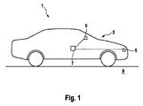
図1は、サラウンドビューシステム3を備えた車両1を示す。サラウンドビューシステム3は、4つのデジタルカメラ5と、カメラ5に電気的に接続されたプロセッサ7とを含む。
FIG. 1 shows a
車両1は、被写体を含む領域の地面9上に位置している。地面9は、水平な平面を有する。被写体は、この図には示されていない。
The
図2に見られるように、車両1は、前輪軸を有する。前輪軸の平面への投影は、地平面を定義する働きをする。車両1は、座標系13を有する基準系12を更に有する。座標系12は、3つの直交軸14、16、及び18と、原点20とを含む。
As can be seen in FIG. 2, the
原点20は、これら3つの直交軸14、16、及び18の交点に位置する。
The
直交軸は、x軸14、y軸16、及びz軸18を含む。x軸14は、車両1の後部を指している。y軸16は、車両1の右側を指している。z軸18は、上方を指している。
The orthogonal axes include the
4つのカメラ5については、車両1の所定位置に位置しており、車両1に対するカメラ5の相対位置は既知であるか、または予め定められている。カメラ5は、領域のシーンに向けられているか、またはその方向を指している。カメラ5の画像は重なり合っているか、共通の被写体または特徴物を有している。
The four
一般的な意味では、サラウンドビューシステム3は、4つのカメラの代わりに2つ以上のカメラを有することができる。 In a general sense, the surround view system 3 can have two or more cameras instead of four cameras.
機能的には、車両1は、人や物資を輸送するために使用される。カメラ5は、被写体の写真または画像を撮影し、画像のデータをプロセッサ7に送るために使用される。プロセッサ7は、画像データを加工するために使用される。
Functionally, the
図3は、以下に説明する車両1の各カメラ5の外部パラメータを決定する方法のフローチャート25を示す。
FIG. 3 shows a
外部パラメータは、各カメラ5の基準系を定義する。特に、外部パラメータは、カメラ基準系の向き及び場所を車両基準系12の向き及び場所と揃えるために、カメラの5の回転と並進とを含む。
The external parameters define the reference system for each
フローチャート25は、車両1が位置する領域のシーンの単一の画像または1つの写真フレームを各カメラ5が撮影するステップ28を含む。カメラ5のシーンの画像29を図4に示す。
The
一般的な意味では、カメラ5は、一連の画像を含むビデオ録画を行ってもよい。その場合、この方法は、ビデオ録画の1つの画像のみに適用される。
In a general sense, the
次いで、画像データは、プロセッサ7に送られる。 The image data is then sent to the processor 7.
フローチャート25は、ステップ28の後に行われる、プロセッサ7が車両1の地面9または地平面のレベルを決定するステップ31を更に含む。その後、車両1の地平面が、画像内の線に従って推定または決定される。
焦点距離及び他のレンズパラメータを含むカメラ5の内部パラメータが、プロセッサ7によって、カメラ5の画像の点32をカメラ5のレンズを通過する対応する光線にマッピングする、または関連づけるために使用される。各点32は、カメラ5の画像センサ画素に対応する。
次いで、プロセッサ7により、カメラ5の外からカメラレンズを通って入射するこれらの光線を表すために単位ベクトルが選択される。単位ベクトルは更に、図5に示す単位球35を定義する。各単位球35が、1つのカメラ5に関連する。
The processor 7 then selects a unit vector to represent these rays incident from outside the
次いで、プロセッサ7により、図6に示すように像点32が単位球35上にマッピングまたは投影される。特に、画像の線のエッジの各点32が、単位球35上に投影される。
The processor 7 then maps or projects the
次いで、プロセッサ7は、ソフトウェアエッジ検出器を使用して単位球35上の各画像における線を決定する。
Processor 7 then uses a software edge detector to determine the lines in each image on the
詳細には、単位球35上の4つの像点ごとに単位球35の表面上の一組の円線が定義される。
Specifically, a set of circles on the surface of the
球面37上の1つの円を定義するには、2つの像点で十分である。
Two image points are sufficient to define one circle on the
次いで、4つの像点が、球面37上の少なくとも2つ1組の円を定義する。この組は、2つの円が2つの点で交差することを特徴とし、それらの交点は、図7に示すように、消失点を定義するための候補として機能することができる。消失点は、これらの交点を通過する線の交点に配置される。
The four image points then define at least a pair of circles on the
球面の4つの円が、単位球35を通る平面Pを定義する4つの交点i1、i2、i3、およびi4を提供する。従って、単位球35を通る平面を定義するための交点の最小数は、4である。
The four circles of the sphere provide the four intersections i1, i2, i3, and i4 that define the plane P passing through the
均質表現を使用すると、3D(三次元)空間における平面は、 Using a homogeneous representation, a plane in 3D (three-dimensional) space is
![]()
![]()
![]()
![]()

![]()
![]()
![]()
![]()
次いで、この3つの可能な平面が、ハフ空間に蓄積される。 The three possible planes are then accumulated in the huff space.
ハフアキュムレータの1つのピークと、法線ベクトルとカメラのy軸16との間の最小角度が、プロセッサによって後に選択され、地面となる。選択されたピークは、おそらく最も高い強度を有する。
The minimum angle between one peak of the Huff accumulator and the normal vector and the y-
一般的な意味では、特徴物は線であり得、特徴物は点、エッジ、または線を含む。 In a general sense, a feature can be a line, which includes a point, edge, or line.
フローチャート25は、ステップ28の後かつステップ31の後に実施される、プロセッサ7が車両基準系12の原点20を、決定された車両1の地平面上に位置するものとして定義するステップ40を更に含む。
特に、原点20とy軸16は地面9の線上に位置し、この線は地平面上の車両1の前輪軸の垂直投影によって定義される。
In particular, the
上記ステップ40の後に、プロセッサ7が、カメラ基準系の向きを車両基準系12の向きと揃えるために、カメラ基準系の回転を計算または決定するステップ45が続く。
The
このカメラ基準系の回転は、カメラ基準系の回転を含む最初のカメラ外部較正から導出することができる。最初のカメラ外部較正は、通常はカメラ5を備える車両を製造した工場で行われる。
The rotation of this camera reference system can be derived from the first external camera calibration involving the rotation of the camera reference system. The first camera external calibration is usually done at the factory that manufactured the vehicle equipped with the
詳細には、車両基準系における地平面に対する法線は、 In detail, the normal to the ground plane in the vehicle reference system is
![]()
![]()
![]()
![]()
![]()
![]()
![]()
![]()
![]()
![]()
![]()
![]()
行列Rはその後、各軸の回転を得るために分解される。 The matrix R is then decomposed to obtain rotation for each axis.
フローチャート25は、ステップ45の後に、プロセッサ7が、カメラ基準系の場所を車両基準系12の場所と整列列させるために、各カメラ基準系の並進を計算または決定するステップ50を含む。
このステップ50は、カメラ5の画像の較正機能を使用して行われる。
This
実際には、カメラ5の位置は時間とともに変化し得る。このステップ50は、カメラの場所の変化を決定することにより、カメラ5のより正確な場所を提供することを意図している。
In practice, the position of the
このカメラ位置の変化の計算は、回帰技術を用いて行われる。 The calculation of this change in camera position is performed using a regression technique.
車両1に対するカメラ5の位置および車両1の寸法は、予め知られているか、決定されている。
The position of the
その後、プロセッサ7は、コーナー検出アルゴリズムを使用して、カメラ5の各画像における一組の較正点を検出または決定する。所定の較正点の組は、線の切り取り、または他の方法を用いて決定することもできる。
The processor 7 then uses a corner detection algorithm to detect or determine a set of calibration points in each image of
その後、プロセッサ7は、以前決定されたカメラ基準系の回転を使用すると共に、カメラ基準系の最初の並進を決定するために使用される前回記録したカメラ位置を使用して、これら検出された較正点を車両基準系12に投影する。
The processor 7 then uses these detected calibrations using the previously determined rotation of the camera reference system and the previously recorded camera position used to determine the first translation of the camera reference system. The point is projected onto the
プロセッサ7は更に、隣接するカメラ5からの較正点を車両基準系に投影する。
Processor 7 also projects calibration points from
その後、プロセッサ7は、スケールと回転不変マッチングアルゴリズムを使用して、前記カメラ5からの投影された較正点を、隣接するカメラ5からの投影された較正点とマッチングする。
The processor 7 then uses a scale and rotation invariant matching algorithm to match the projected calibration points from the
次いで、較正点のマッチングの何らかの誤差が、それぞれのカメラ5の新しい場所を推定または決定するために使用される。
Any error in matching the calibration points is then used to estimate or determine a new location for each
一般的な意味では、ロボットやマシンビジョンなどの他の装置もカメラ5のこの較正方法を適用することができる。
In a general sense, other devices such as robots and machine vision can also apply this calibration method for
上記の説明は多くの特異性を含むが、これは実施形態の範囲を限定するものと解釈すべきではなく、予見可能な実施形態の説明を提供するに過ぎない。上述した実施形態の利点は、とりわけ実施形態の範囲を限定するものとして解釈すべきではなく、記載された実施形態が実施される場合に可能な成果を説明するものと解釈すべきである。したがって、実施形態の範囲は、与えられた例ではなく、請求項およびその均等物によって決定すべきである。 Although the above description involves many specificities, this should not be construed as limiting the scope of the embodiments, but merely provides a foreseeable description of the embodiments. The advantages of the embodiments described above should not be construed as limiting the scope of the embodiments in particular, but should be construed as explaining possible outcomes when the described embodiments are implemented. Therefore, the scope of the embodiment should be determined by the claims and their equivalents, not by the given example.
1 車両
3 サラウンドビューシステム
5 カメラ
7 プロセッサ
9 地面
12 基準系
13 座標系
14 x軸
16 y軸
18 z軸
20 原点
25 フローチャート
28 ステップ
29 画像
31 ステップ
32 像点
35 単位球
37 球面
40 ステップ
45 ステップ
50 ステップ
i1 交点
i2 交点
i3 交点
i4 交点
1 Vehicle 3
Claims (14)
− 各カメラ(28)によりシーンの画像を撮影することと、
− 前記画像(31)の特徴物に従って前記車両の地平面を決定することと、
− 前記車両の基準系の原点を前記地平面(40)上に位置するものとして定義することと、
− 前記カメラの基準系の前記車両基準系(40、45、50)における並進を決定することを含み、
− 前記カメラ基準系の前記並進の決定が、前記カメラからの較正対象の画像と、前記カメラの近傍に備え付けられ前記車両(50)に搭載された少なくとも1つの他のカメラからの較正対象の画像に従って実施され、前記画像(31)の特徴物に従って前記車両の地平面を決定するステップが、前記画像中の一組のエッジ点の内の4点のサブセットを決定することによる消失点の検出と、その4点からの3つの平面の導出と、それに続く、全ての導出された当該平面が表現され蓄積されているハフ空間における、車両の地平面の選択と
を含むことを特徴とする、方法。 How to calibrate the vehicle's camera
− Taking an image of the scene with each camera (28)
-Determining the horizon of the vehicle according to the features in image (31)
-Defining the origin of the reference system of the vehicle as being located on the ground plane (40)
-Including determining the translation of the camera reference system in the vehicle reference system (40, 45, 50).
-The translation determination of the camera reference system is an image to be calibrated from the camera and an image to be calibrated from at least one other camera mounted in the vehicle (50) in the vicinity of the camera. The step of determining the ground plane of the vehicle according to the features of the image (31) is the detection of vanishing points by determining a subset of four points within a set of edge points in the image. A method comprising the derivation of three planes from the four points, followed by the selection of the ground plane of the vehicle in the Huff space in which all the derived planes are represented and accumulated. ..
− スケールと回転不変マッチングアルゴリズムを使用して前記カメラからの前記較正対象の前記画像をマッチングすることと、
− 前記較正対象の前記マッチングの何らかの不一致を使用して前記カメラの位置を決定することを含む、請求項1から5のいずれか一項に記載の方法。 -The determination of the translation of the camera reference system (50)
-Matching the image to be calibrated from the camera using a scale and rotation invariant matching algorithm, and
-The method of any one of claims 1-5, comprising locating the camera using some mismatch of the matching of the calibrated object.
− カメラ画像を受信し、
− 前記カメラの画像の特徴物に従って車両の地平面を決定し、
− 前記車両の基準系の原点を前記地平面上に位置するものとして定義し、
− 前記カメラの基準系の前記車両基準系における並進を決定するためのプログラムコード指令を含み、前記画像の特徴物に従って車両の地平面を決定するためのプログラムコード指令が、前記画像中の一組のエッジ点の内の4点のサブセットを決定することによる消失点の検出と、その4点から3つの平面の導出と、それに続く、ハフ空間に表現される全ての導出された当該平面の蓄積と、当該ハフ空間における地平面の選択と
のためのプログラムコード指令を含むことを特徴とするコンピュータが実行可能なプログラムコード指令が格納されたコンピュータ可読記憶媒体を含む、コンピュータプログラム製品。 -A computer-executable program code directive
− Receive camera image
-Determine the event horizon according to the features of the camera image,
-Define the origin of the reference system of the vehicle as being located on the ground plane.
-A set of program code commands in the image for determining the ground plane of the vehicle according to the features of the image, including a program code command for determining the translation of the reference system of the camera in the vehicle reference system. Detection of vanishing points by determining a subset of 4 of the edge points of, and derivation of 3 planes from those 4 points, followed by accumulation of all derived planes represented in Huff space. A computer program product comprising a computer-readable storage medium containing program code instructions that can be executed by a computer, including program code instructions for selecting a ground plane in the Huff space.
− 前記少なくとも2つのカメラポートからの画像データを処理するプロセッサ(7)を備え、
前記プロセッサ(7)が、
− 前記カメラポートの少なくとも1つからの前記画像データの特徴物に従って車両の地平面を決定し、
− 前記車両の基準系の原点を前記地平面上に位置するものとして定義し、
− 前記カメラの基準系の前記車両基準系における並進を決定するように適合され、
前記カメラ基準系の前記並進の決定が、1つのカメラポートからの較正対象の画像データと別のカメラポートからの前記較正対象の画像データに従って実施され、前記画像(31)の特徴物に従って前記車両の地平面を決定するステップが、前記画像中の一組のエッジ点の内の4点のサブセットを決定することによる消失点の検出と、その4点からの3つの平面の導出と、それに続く、ハフ空間に表現される全ての導出された当該平面の蓄積と、当該ハフ空間における地平面の選択と
を含むことを特徴とする、カメラ制御ユニット。 -At least two camera ports, one port provided to connect to and attach to the corresponding vehicle camera,
-Equipped with a processor (7) for processing image data from at least two camera ports.
The processor (7)
-Determine the horizon of the vehicle according to the features of the image data from at least one of the camera ports.
-Define the origin of the reference system of the vehicle as being located on the ground plane.
-Adapted to determine the translation of the camera's frame of reference in the vehicle's frame of reference.
The translation determination of the camera reference system is performed according to the image data to be calibrated from one camera port and the image data to be calibrated from another camera port, and the vehicle according to the feature of the image (31). The steps to determine the ground plane of the image are the detection of vanishing points by determining a subset of four points in the set of edge points in the image, the derivation of three planes from the four points, and the subsequent steps. , A camera control unit comprising accumulating all derived planes represented in the huff space and selecting a ground plane in the huff space.
− 請求項10から12のいずれか一項に記載のカメラ制御ユニットであって、カメラポートが前記カメラ(5)に接続されているカメラ制御ユニットを備える、カメラモジュール。 -At least two cameras (5) for mounting on the vehicle (1),
-A camera module according to any one of claims 10 to 12, further comprising a camera control unit whose camera port is connected to the camera (5).
少なくとも2つのカメラ(5)と、前記カメラモジュールのプロセッサ(7)が取り付けられている、車両(1)。 − A vehicle including the camera module according to claim 13.
A vehicle (1) to which at least two cameras (5) and a processor (7) of the camera module are mounted.
Applications Claiming Priority (3)
| Application Number | Priority Date | Filing Date | Title |
|---|---|---|---|
| EP15164760.9A EP3086284A1 (en) | 2015-04-23 | 2015-04-23 | Camera extrinsic parameters estimation from image lines |
| EP15164760.9 | 2015-04-23 | ||
| PCT/EP2016/057746 WO2016169790A1 (en) | 2015-04-23 | 2016-04-08 | Camera extrinsic parameters estimation from image lines |
Publications (3)
| Publication Number | Publication Date |
|---|---|
| JP2018519696A JP2018519696A (en) | 2018-07-19 |
| JP2018519696A5 JP2018519696A5 (en) | 2019-01-17 |
| JP6767998B2 true JP6767998B2 (en) | 2020-10-14 |
Family
ID=53177095
Family Applications (1)
| Application Number | Title | Priority Date | Filing Date |
|---|---|---|---|
| JP2017554478A Active JP6767998B2 (en) | 2015-04-23 | 2016-04-08 | Estimating external parameters of the camera from the lines of the image |
Country Status (6)
| Country | Link |
|---|---|
| US (1) | US10719955B2 (en) |
| EP (1) | EP3086284A1 (en) |
| JP (1) | JP6767998B2 (en) |
| KR (1) | KR102516326B1 (en) |
| DE (1) | DE112016001150T5 (en) |
| WO (1) | WO2016169790A1 (en) |
Families Citing this family (13)
| Publication number | Priority date | Publication date | Assignee | Title |
|---|---|---|---|---|
| US11370422B2 (en) * | 2015-02-12 | 2022-06-28 | Honda Research Institute Europe Gmbh | Method and system in a vehicle for improving prediction results of an advantageous driver assistant system |
| CN108805934B (en) * | 2017-04-28 | 2021-12-28 | 华为技术有限公司 | External parameter calibration method and device for vehicle-mounted camera |
| CN109086650B (en) * | 2017-06-14 | 2022-04-12 | 现代摩比斯株式会社 | Calibration method and calibration apparatus |
| US11158088B2 (en) | 2017-09-11 | 2021-10-26 | Tusimple, Inc. | Vanishing point computation and online alignment system and method for image guided stereo camera optical axes alignment |
| US11089288B2 (en) * | 2017-09-11 | 2021-08-10 | Tusimple, Inc. | Corner point extraction system and method for image guided stereo camera optical axes alignment |
| US10621753B2 (en) * | 2017-09-29 | 2020-04-14 | Intel IP Corporation | Extrinsic calibration of camera systems |
| CN112930557A (en) * | 2018-09-26 | 2021-06-08 | 相干逻辑公司 | Any world view generation |
| EP3629292A1 (en) * | 2018-09-27 | 2020-04-01 | Continental Automotive GmbH | Reference point selection for extrinsic parameter calibration |
| US10848744B2 (en) | 2019-02-27 | 2020-11-24 | Ford Global Technologies, Llc | Vehicle camera alignment |
| CN110728720B (en) * | 2019-10-21 | 2023-10-13 | 阿波罗智能技术(北京)有限公司 | Method, apparatus, device and storage medium for camera calibration |
| US11410334B2 (en) * | 2020-02-03 | 2022-08-09 | Magna Electronics Inc. | Vehicular vision system with camera calibration using calibration target |
| SE544405C2 (en) * | 2020-09-30 | 2022-05-10 | Scania Cv Ab | Method and control arrangement for extrinsic calibration of a camera arranged at a vehicle |
| CN112819711B (en) * | 2021-01-20 | 2022-11-22 | 电子科技大学 | Monocular vision-based vehicle reverse positioning method utilizing road lane line |
Family Cites Families (9)
| Publication number | Priority date | Publication date | Assignee | Title |
|---|---|---|---|---|
| US8373763B2 (en) * | 2008-05-22 | 2013-02-12 | GM Global Technology Operations LLC | Self calibration of extrinsic camera parameters for a vehicle camera |
| JP5455124B2 (en) * | 2010-04-01 | 2014-03-26 | 国立大学法人鳥取大学 | Camera posture parameter estimation device |
| DE102010023162A1 (en) * | 2010-06-09 | 2011-12-15 | Valeo Schalter Und Sensoren Gmbh | A method for assisting a driver of a motor vehicle when parking in a parking space, Fahrerassistzeinrichtung and motor vehicle |
| EP2523163B1 (en) * | 2011-05-10 | 2019-10-16 | Harman Becker Automotive Systems GmbH | Method and program for calibrating a multicamera system |
| JP5898475B2 (en) * | 2011-11-28 | 2016-04-06 | クラリオン株式会社 | In-vehicle camera system, calibration method thereof, and calibration program thereof |
| US10652466B2 (en) * | 2015-02-16 | 2020-05-12 | Applications Solutions (Electronic and Vision) Ltd | Method and device for stabilization of a surround view image |
| JP6573361B2 (en) * | 2015-03-16 | 2019-09-11 | キヤノン株式会社 | Image processing apparatus, image processing system, image processing method, and computer program |
| US9996749B2 (en) * | 2015-05-29 | 2018-06-12 | Accenture Global Solutions Limited | Detecting contextual trends in digital video content |
| US10008000B2 (en) * | 2016-05-18 | 2018-06-26 | Conduent Business Services, Llc | Camera calibration based on moving vehicle line segments |
-
2015
- 2015-04-23 EP EP15164760.9A patent/EP3086284A1/en not_active Ceased
-
2016
- 2016-04-08 WO PCT/EP2016/057746 patent/WO2016169790A1/en active Application Filing
- 2016-04-08 JP JP2017554478A patent/JP6767998B2/en active Active
- 2016-04-08 KR KR1020177030394A patent/KR102516326B1/en active IP Right Grant
- 2016-04-08 DE DE112016001150.4T patent/DE112016001150T5/en active Pending
-
2017
- 2017-10-13 US US15/783,185 patent/US10719955B2/en active Active
Also Published As
| Publication number | Publication date |
|---|---|
| JP2018519696A (en) | 2018-07-19 |
| US20180040141A1 (en) | 2018-02-08 |
| WO2016169790A1 (en) | 2016-10-27 |
| KR102516326B1 (en) | 2023-03-30 |
| EP3086284A1 (en) | 2016-10-26 |
| KR20170139548A (en) | 2017-12-19 |
| DE112016001150T5 (en) | 2018-06-21 |
| US10719955B2 (en) | 2020-07-21 |
Similar Documents
| Publication | Publication Date | Title |
|---|---|---|
| JP6767998B2 (en) | Estimating external parameters of the camera from the lines of the image | |
| JP6522076B2 (en) | Method, apparatus, storage medium and program product for lateral vehicle positioning | |
| CN108692719B (en) | Object detection device | |
| US20190120934A1 (en) | Three-dimensional alignment of radar and camera sensors | |
| JP5455124B2 (en) | Camera posture parameter estimation device | |
| CN111336951B (en) | Method and apparatus for calibrating external parameters of image sensor | |
| CN109155066B (en) | Method for motion estimation between two images of an environmental region of a motor vehicle, computing device, driver assistance system and motor vehicle | |
| CN110176038B (en) | Method, system and storage medium for calibrating camera of vehicle | |
| JP2006252473A (en) | Obstacle detector, calibration device, calibration method and calibration program | |
| JP2018124787A (en) | Information processing device, data managing device, data managing system, method, and program | |
| US20140085409A1 (en) | Wide fov camera image calibration and de-warping | |
| KR20090103165A (en) | Monocular Motion Stereo-Based Free Parking Space Detection Apparatus and Method | |
| US11887336B2 (en) | Method for estimating a relative position of an object in the surroundings of a vehicle and electronic control unit for a vehicle and vehicle | |
| JP2004198212A (en) | Apparatus for monitoring vicinity of mobile object | |
| CA3044322A1 (en) | Self-calibrating sensor system for a wheeled vehicle | |
| Beck et al. | Generalized B-spline camera model | |
| KR20200118073A (en) | System and method for dynamic three-dimensional calibration | |
| KR102490521B1 (en) | Automatic calibration through vector matching of the LiDAR coordinate system and the camera coordinate system | |
| EP3629292A1 (en) | Reference point selection for extrinsic parameter calibration | |
| KR20240056516A (en) | Method and system for generating camera model for camera calibration | |
| JP6886136B2 (en) | Alignment device, alignment method and computer program for alignment | |
| WO2022133986A1 (en) | Accuracy estimation method and system | |
| CN113959435A (en) | Vehicle-mounted all-around online SLAM system and method based on multi-camera model | |
| JP6670712B2 (en) | Self-position estimation device, moving object and self-position estimation method | |
| US20240112363A1 (en) | Position estimation system, position estimation method, and program |
Legal Events
| Date | Code | Title | Description |
|---|---|---|---|
| A521 | Request for written amendment filed |
Free format text: JAPANESE INTERMEDIATE CODE: A523 Effective date: 20181203 |
|
| A621 | Written request for application examination |
Free format text: JAPANESE INTERMEDIATE CODE: A621 Effective date: 20181203 |
|
| A977 | Report on retrieval |
Free format text: JAPANESE INTERMEDIATE CODE: A971007 Effective date: 20191115 |
|
| A131 | Notification of reasons for refusal |
Free format text: JAPANESE INTERMEDIATE CODE: A131 Effective date: 20191127 |
|
| A521 | Request for written amendment filed |
Free format text: JAPANESE INTERMEDIATE CODE: A523 Effective date: 20200213 |
|
| A131 | Notification of reasons for refusal |
Free format text: JAPANESE INTERMEDIATE CODE: A131 Effective date: 20200422 |
|
| A521 | Request for written amendment filed |
Free format text: JAPANESE INTERMEDIATE CODE: A523 Effective date: 20200525 |
|
| RD04 | Notification of resignation of power of attorney |
Free format text: JAPANESE INTERMEDIATE CODE: A7424 Effective date: 20200703 |
|
| TRDD | Decision of grant or rejection written | ||
| A01 | Written decision to grant a patent or to grant a registration (utility model) |
Free format text: JAPANESE INTERMEDIATE CODE: A01 Effective date: 20200826 |
|
| A61 | First payment of annual fees (during grant procedure) |
Free format text: JAPANESE INTERMEDIATE CODE: A61 Effective date: 20200918 |
|
| R150 | Certificate of patent or registration of utility model |
Ref document number: 6767998 Country of ref document: JP Free format text: JAPANESE INTERMEDIATE CODE: R150 |
|
| R250 | Receipt of annual fees |
Free format text: JAPANESE INTERMEDIATE CODE: R250 |