JP6766864B2 - Mobile radiation device - Google Patents
Mobile radiation device Download PDFInfo
- Publication number
- JP6766864B2 JP6766864B2 JP2018502920A JP2018502920A JP6766864B2 JP 6766864 B2 JP6766864 B2 JP 6766864B2 JP 2018502920 A JP2018502920 A JP 2018502920A JP 2018502920 A JP2018502920 A JP 2018502920A JP 6766864 B2 JP6766864 B2 JP 6766864B2
- Authority
- JP
- Japan
- Prior art keywords
- spring
- wire
- pulley
- column
- intermediate material
- Prior art date
- Legal status (The legal status is an assumption and is not a legal conclusion. Google has not performed a legal analysis and makes no representation as to the accuracy of the status listed.)
- Active
Links
- 230000005855 radiation Effects 0.000 title claims description 85
- 230000006835 compression Effects 0.000 claims description 80
- 238000007906 compression Methods 0.000 claims description 80
- 239000000463 material Substances 0.000 claims description 52
- 230000007246 mechanism Effects 0.000 claims description 50
- 238000002601 radiography Methods 0.000 claims description 5
- 230000001678 irradiating effect Effects 0.000 claims description 3
- 230000000149 penetrating effect Effects 0.000 claims 1
- 230000000694 effects Effects 0.000 description 11
- 230000004048 modification Effects 0.000 description 9
- 238000012986 modification Methods 0.000 description 9
- 238000010586 diagram Methods 0.000 description 8
- 239000012634 fragment Substances 0.000 description 8
- 238000005192 partition Methods 0.000 description 7
- 230000008602 contraction Effects 0.000 description 2
- 230000006866 deterioration Effects 0.000 description 2
- 230000002093 peripheral effect Effects 0.000 description 2
- 230000001174 ascending effect Effects 0.000 description 1
- 230000005540 biological transmission Effects 0.000 description 1
- 239000002131 composite material Substances 0.000 description 1
- 230000007423 decrease Effects 0.000 description 1
- 238000006073 displacement reaction Methods 0.000 description 1
- 239000012779 reinforcing material Substances 0.000 description 1
- 238000004804 winding Methods 0.000 description 1
Images


Classifications
-
- A—HUMAN NECESSITIES
- A61—MEDICAL OR VETERINARY SCIENCE; HYGIENE
- A61B—DIAGNOSIS; SURGERY; IDENTIFICATION
- A61B6/00—Apparatus or devices for radiation diagnosis; Apparatus or devices for radiation diagnosis combined with radiation therapy equipment
- A61B6/44—Constructional features of apparatus for radiation diagnosis
- A61B6/4429—Constructional features of apparatus for radiation diagnosis related to the mounting of source units and detector units
- A61B6/447—Constructional features of apparatus for radiation diagnosis related to the mounting of source units and detector units the source unit or the detector unit being mounted to counterpoise or springs
-
- A—HUMAN NECESSITIES
- A61—MEDICAL OR VETERINARY SCIENCE; HYGIENE
- A61B—DIAGNOSIS; SURGERY; IDENTIFICATION
- A61B6/00—Apparatus or devices for radiation diagnosis; Apparatus or devices for radiation diagnosis combined with radiation therapy equipment
- A61B6/44—Constructional features of apparatus for radiation diagnosis
- A61B6/4405—Constructional features of apparatus for radiation diagnosis the apparatus being movable or portable, e.g. handheld or mounted on a trolley
-
- A—HUMAN NECESSITIES
- A61—MEDICAL OR VETERINARY SCIENCE; HYGIENE
- A61B—DIAGNOSIS; SURGERY; IDENTIFICATION
- A61B6/00—Apparatus or devices for radiation diagnosis; Apparatus or devices for radiation diagnosis combined with radiation therapy equipment
- A61B6/58—Testing, adjusting or calibrating thereof
- A61B6/588—Setting distance between source unit and detector unit
-
- H—ELECTRICITY
- H05—ELECTRIC TECHNIQUES NOT OTHERWISE PROVIDED FOR
- H05G—X-RAY TECHNIQUE
- H05G1/00—X-ray apparatus involving X-ray tubes; Circuits therefor
- H05G1/02—Constructional details
Landscapes
- Health & Medical Sciences (AREA)
- Life Sciences & Earth Sciences (AREA)
- Medical Informatics (AREA)
- Engineering & Computer Science (AREA)
- Radiology & Medical Imaging (AREA)
- Biomedical Technology (AREA)
- Biophysics (AREA)
- Nuclear Medicine, Radiotherapy & Molecular Imaging (AREA)
- Optics & Photonics (AREA)
- Pathology (AREA)
- Physics & Mathematics (AREA)
- High Energy & Nuclear Physics (AREA)
- Heart & Thoracic Surgery (AREA)
- Molecular Biology (AREA)
- Surgery (AREA)
- Animal Behavior & Ethology (AREA)
- General Health & Medical Sciences (AREA)
- Public Health (AREA)
- Veterinary Medicine (AREA)
- Apparatus For Radiation Diagnosis (AREA)
Description
本発明は、回診に用いられる移動型放射線装置に関し、特に、放射線源の高さを調節する機構を備える移動型放射線撮影装置に関するものである。 The present invention relates to a mobile radiation apparatus used for rounds, and more particularly to a mobile radiographing apparatus provided with a mechanism for adjusting the height of a radiation source.
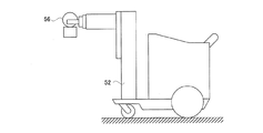
図13は、従来構成の移動型放射線装置を説明している。この装置は、手押し式の台車に放射線を照射する放射線源56と放射線源56を支持する鉛直方向に伸びる支柱52を備えており、支柱52は放射線源56を摺動に支持する。放射線源56は、支柱52に支持されながら鉛直方向に移動される構成となっている。この様な装置は、電動のアシストがついており、操作者が強い力を加えて手押しをしなくても容易に移動ができるように工夫されている。
FIG. 13 illustrates a mobile radiation device having a conventional configuration. This device includes a
この様な移動型放射線装置は、被検体の病室まで移動させることができる。この装置を使えば、被検体を極力移動させることなく被検体の放射線撮影をすることが可能となる。 Such a mobile radiation device can be moved to the patient's room of the subject. By using this device, it is possible to take radiographs of a subject without moving the subject as much as possible.
図14は、放射線源56を鉛直方向の移動を実現させる機構を模式的に説明している。図14の左側は、この装置には典型的な機構で、放射線源56と同じ重さのカウンターウェートWを利用したものとなっている。すなわち、図14左側の装置は、一端が放射線源56に接続され、他端がカウンターウェートWに接続されるワイヤを有し、ワイヤは、プーリに保持されている。このようにして、放射線源56とカウンターウェートWとは、釣瓶式の機構により関連づけられている。そして、ワイヤの一端側にかかる荷重は、他端側の荷重に等しくなっている。したがって、放射線源56とカウンターウェートWとは互いに釣り合い、ひとりでに動いてしまうことがない。そして、放射線源56に力を加えれば、放射線源56は容易に上下移動する。
FIG. 14 schematically describes a mechanism for realizing the vertical movement of the
放射線源56は、かなりの荷重を有する。図14左側の機構は、放射線源56と同じ重さのカウンターウェートWが必要だから、放射線源56を装置に装備すると、放射線源56もう一つ分の重量だけ余計に装置が重くなる。したがって、この機構を採用した移動型放射線撮影装置は、かなり重くなってしまう。移動型放射線撮影装置の重量があると、それだけ移動させにくくなる。
The
そこで、移動型放射線撮影装置を軽量化させることができる機構が考え出されている(特許文献1参照)。図14の右側は、この新たな機構について説明している。この機構は、図14左側のカウンターウェートWが引っ張りバネに変更された構成である。カウンターウェートWを取り除いたことにより、ほぼ放射線源56の重量相当分だけ装置の軽量化ができる。
Therefore, a mechanism has been devised that can reduce the weight of the mobile radiography apparatus (see Patent Document 1). The right side of FIG. 14 describes this new mechanism. This mechanism has a configuration in which the counter weight W on the left side of FIG. 14 is changed to a tension spring. By removing the counter weight W, the weight of the device can be reduced by approximately the weight of the
図14右側に示す機構においては、放射線源56がプーリに伝える力と引っ張りバネの張力が互いに釣り合った状態となる。したがって、放射線源56とバネの張力とは互いに釣り合い、ひとりでに動いてしまうことがない。そして、放射線源56に力を加えれば、放射線源56は容易に上下移動する。
In the mechanism shown on the right side of FIG. 14, the force transmitted by the
引っ張りバネは、バネの伸びが変わると張力が変わる性質を有している。したがって、放射線源56の荷重とバネの張力を常に釣り合わせるようにするには、工夫が必要である。図14右側のプーリは、螺旋と円筒形の巻き取りドラムを組み合わせたものである。この場合の螺旋とは、言わば、回転角度により半径が変化する輪軸を有する定滑車である。螺旋としては、具体的にはアルキメデスの螺旋が例示できるが、必ずしもアルキメデスの螺旋を用いる必要は無い。引っ張りバネは伸びると、張力が強くなるが、その分だけ螺旋の半径が減少し、逆に引っ張りバネが縮んで張力が弱くなると、その分だけ螺旋の半径が増加するので、結果として、プーリには常に同じトルクが働く。したがって、放射線源56は、カウンターウェートWを用いたときと同じような挙動で上下動される。
The tension spring has the property that the tension changes when the elongation of the spring changes. Therefore, in order to always balance the load of the
しかしながら、従来構成の移動型放射線装置には次のような問題点がある。
すなわち、従来構成の移動型放射線装置は、安全性において未熟な点がある。However, the mobile radiation device having the conventional configuration has the following problems.
That is, the mobile radiation device having the conventional configuration has an immature point in terms of safety.
図14右側で説明した引っ張りバネは、経年劣化等により断絶することがある。このバネの断絶を防ぐのは容易なことではない。図15左側は、引っ張りバネが断絶した様子を示している。引っ張りバネは、経年劣化が進むと、突然断絶し、図15右側に示すように前後が分断されたようなかたちとなってしまう。すると、放射線源56の落下を制止する力が消失し、放射線源56が鉛直下向きに滑り落ちてしまう。
The tension spring described on the right side of FIG. 14 may be cut off due to aged deterioration or the like. It is not easy to prevent this spring from breaking. The left side of FIG. 15 shows how the tension spring is cut off. As the tension spring deteriorates over time, it suddenly breaks, and as shown on the right side of FIG. 15, the front and rear are divided. Then, the force for stopping the fall of the
この様な事情があるので、従来構成は、荷重物となっている放射線源56が落下しても安全性が保てるように工夫がされている。すなわち、従来構成には、放射線源56の落下を防ぐ安全機構が別途に設けられている。したがって、引っ張りバネが切れても、実際的には放射線源56がそのまま落下して事故に繋がるという事態は避けられる。
Due to such circumstances, the conventional configuration has been devised so that safety can be maintained even if the
とはいえ、安全機構は、必ずしも完全に作動するとは限らない。また、引っ張りバネが断絶してから安全装置が作動するまでの時間を完全になくすことは難しい。安全機構を備えていたとしても、引っ張りバネが断絶すると放射線源56は、ある程度ずり下がってしまうのである。このような事情は、装置の安全性の観点から望ましくない。
However, safety mechanisms do not always work perfectly. In addition, it is difficult to completely eliminate the time from when the tension spring is cut off until the safety device is activated. Even if a safety mechanism is provided, the
本発明は、この様な事情に鑑みてなされたものであって、その目的は、安全性の高い移動型放射線装置を提供することにある。 The present invention has been made in view of such circumstances, and an object of the present invention is to provide a highly safe mobile radiation apparatus.
本発明は上述の課題を解決するために次のような構成をとる。
すなわち、本発明に係る移動型放射線装置は、放射線を照射する放射線源と、放射線源を昇降自在に支持する鉛直方向に伸びる支柱と、放射線源と支柱とに挟まれる位置に設けられるとともに放射線源の昇降移動に伴って昇降移動する中間材と、一端が中間材に接続されているとともに、他端が支柱の内側に接続されている支柱内ワイヤと、支柱内ワイヤを支持するとともに、支柱の内部に設けられる支柱にとっての定滑車となっている支柱内プーリと、支柱内プーリから見て支柱内ワイヤの他端側に設けられているとともに、支柱内ワイヤに巻き掛けられている動滑車と、支柱内ワイヤに張力を付与するバネ機構を支柱の内部に備えている移動型放射線装置において、バネ機構は、(A)上端と下端とを有し、上端が支柱の内側で固定される圧縮バネと、(B)一端が動滑車に接続されており、圧縮バネの上端を介して圧縮バネを貫通し、圧縮バネの下端に固定されるシャフトを備えることを特徴とするものである。
The present invention has the following configuration in order to solve the above-mentioned problems.
That is, the mobile radiation device according to the present invention is provided at a position sandwiched between the radiation source for irradiating the radiation, the support column extending in the vertical direction for supporting the radiation source in an ascending / descending manner, and the radiation source and the radiation source. Supports the intermediate material that moves up and down as it moves up and down, the wire inside the strut that is connected to the intermediate material at one end and the other end is connected to the inside of the strut, and the wire inside the strut. A pulley inside the strut, which is a fixed slide for the strut provided inside, and a moving glider , which is provided on the other end side of the wire inside the strut when viewed from the pulley inside the strut and is wound around the wire inside the strut. In a mobile radiation device having a spring mechanism inside the strut that applies tension to the wires in the strut, the spring mechanism has (A) an upper end and a lower end, and the upper end is fixed inside the strut. a spring, is characterized in further comprising a shaft fixed to (B) has one end connected to the movable pulley, through the compression spring via the upper end of the compression spring, the lower end of the compression spring.
[作用・効果]本発明によれば、安全性の高い移動型放射線装置を提供することができる。引っ張りバネを用いた従来構成の場合、バネが断絶すると、断片同士は際限なく離れていってしまう。これが放射線源の落下の原因となる。そこで、本発明は、引っ張りバネの代わりに圧縮バネを用いている。本発明のバネ機構によれば、圧縮バネに断絶が生じたとしても、圧縮バネの断片は、先端座から中継バネ座までの間までしか動けない。この様な事情は圧縮バネについても同じで、断絶しても、断片は、末端座から中継バネ座までの間までしか動けない。バネの断絶に合わせてシャフトが大きく動こうとしても引っかかり合って身動きが取れなくなったバネの断片が邪魔をしてそれを許さないからである。この様な原理によりバネが断絶しても放射線源が落下することがない。
しかしながら、圧縮バネは、長くなればなるほど、屈曲しやすくなる特性がある。圧縮バネは、ストロークの確保が難しいのである。そこで、本発明において考え出されたのが複数の圧縮バネを連結させる中継バネ座である。これにより、圧縮バネを直列につなぎ合わせても圧縮バネが座屈しなくなる。すなわち、中継バネ座は、シャフトに案内される構成となっており、バネの延伸方向と直交する横方向に逃げ出すことがない。個別の圧縮バネは、十分に短く、座屈することがない。[Action / Effect] According to the present invention, it is possible to provide a highly safe mobile radiation device. In the conventional configuration using a tension spring, if the spring is broken, the fragments will be infinitely separated from each other. This causes the radiation source to fall. Therefore, the present invention uses a compression spring instead of the tension spring. According to the spring mechanism of the present invention, even if the compression spring is interrupted, the compression spring fragment can move only from the tip seat to the relay spring seat. This situation is the same for compression springs, and even if the spring is disconnected, the fragment can move only from the end seat to the relay spring seat. This is because even if the shaft tries to move a lot in accordance with the disconnection of the spring, the fragment of the spring that gets stuck and gets stuck interferes and does not allow it. Due to this principle, the radiation source does not fall even if the spring is cut off.
However, the compression spring has a characteristic that the longer it is, the easier it is to bend. It is difficult to secure the stroke of the compression spring. Therefore, what has been devised in the present invention is a relay spring seat that connects a plurality of compression springs. As a result, even if the compression springs are connected in series, the compression springs do not buckle. That is, the relay spring seat is configured to be guided by the shaft, and does not escape in the lateral direction orthogonal to the extension direction of the spring. The individual compression springs are short enough that they do not buckle.
また、上述の移動型放射線装置において、バネ機構を構成する圧縮バネに連接するとともにシャフトをガイドする先端バネ座を備えればより望ましい。
Further, in the above mobile radiation device, more desirable if Sonaere tip spring seat for guiding the shaft as well as connected to the compression bar Ne constituting a spring mechanism.
[作用・効果]上述の構成によれば、先端バネ座によりシャフトが確実にガイドされる構成が提供できる。 [Action / Effect] According to the above configuration, it is possible to provide a configuration in which the shaft is reliably guided by the tip spring seat.
また、上述の移動型放射線装置において、先端バネ座が自動調心機構を備えていればより望ましい。 Further, in the above-mentioned mobile radiation device, it is more desirable if the tip spring seat is provided with an automatic centering mechanism.
[作用・効果]上述の構成によれば、先端バネ座は、傾いたシャフトをスムーズにガイドすることができる。 [Action / Effect] According to the above configuration, the tip spring seat can smoothly guide the tilted shaft.
また、上述の移動型放射線撮影装置において、一端が放射線源に接続されているとともに、他端が支柱あるいはそれが設置される基台に接続される中間材ワイヤと、中間材ワイヤを支持するとともに、中間材にとっての定滑車となっている中間材プーリを備えればより望ましい。 Further, in the above-mentioned mobile radiography apparatus, one end is connected to a radiation source, and the other end supports an intermediate material wire connected to a support column or a base on which the intermediate material wire is installed, and an intermediate material wire. , It is more desirable to have an intermediate material pulley that is a fixed pulley for the intermediate material.
[作用・効果]本発明は、中間材の移動をより具体的に示した一例である。本発明は従来構成の機構に組み込んで実施することができる。 [Action / Effect] The present invention is an example showing the movement of the intermediate material more concretely. The present invention can be implemented by incorporating it into a mechanism having a conventional configuration.
また、上述の移動型放射線装置において、中間材ワイヤが多重となっていればより望ましい。 Further, in the above-mentioned mobile radiation device, it is more desirable if the intermediate material wires are multiplexed.
[作用・効果]上述の構成は、本発明のより望ましい構成を表している。中間材ワイヤが多重となっていれば、より安全性の高い移動型放射線装置が提供できる。 [Action / Effect] The above-mentioned configuration represents a more desirable configuration of the present invention. If the intermediate material wires are multiplexed, a more safe mobile radiation device can be provided.
また、上述の移動型放射線装置において、支柱内ワイヤが多重となっていればより望ましい。 Further, in the above-mentioned mobile radiation device, it is more desirable if the wires in the columns are multiplexed.
[作用・効果]上述の構成は、本発明のより望ましい構成を表している。支柱内ワイヤが多重となっていれば、より安全性の高い移動型放射線装置が提供できる。 [Action / Effect] The above-mentioned configuration represents a more desirable configuration of the present invention. If the wires in the columns are multiplex, a more safe mobile radiation device can be provided.
また、上述の移動型放射線装置において、支柱内ワイヤの切断を感知するセンサを備えればより望ましい。 Further, in the above-mentioned mobile radiation device, it is more desirable to include a sensor for detecting the disconnection of the wire in the column.
[作用・効果]上述の構成は、本発明のより望ましい構成を表している。支柱内ワイヤの切断を感知するセンサを備えれば、より安全性の高い移動型放射線装置が提供できる。 [Action / Effect] The above-mentioned configuration represents a more desirable configuration of the present invention. If a sensor that detects the disconnection of the wire in the column is provided, a safer mobile radiation device can be provided.
本発明によれば、安全性の高い移動型放射線装置を提供することができる。引っ張りバネを用いた従来構成の場合、バネが断絶すると、断片同士は際限なく離れていってしまう。そこで、本発明は、代わりに圧縮バネを用いている。本発明のバネ機構によれば、バネの断絶に合わせてシャフトが大きく動こうとしても引っかかり合って身動きが取れなくなったバネの断片が邪魔をしてそれを許さない。そして、本発明において考え出されたのが複数の圧縮バネを連結させる中継バネ座である。これにより、圧縮バネを直列につなぎ合わせても圧縮バネが座屈しなくなる。 According to the present invention, it is possible to provide a mobile radiation device with high safety. In the conventional configuration using a tension spring, if the spring is broken, the fragments will be infinitely separated from each other. Therefore, the present invention uses a compression spring instead. According to the spring mechanism of the present invention, even if the shaft tries to move greatly in accordance with the disconnection of the spring, the fragments of the spring that are caught and stuck are obstructed and do not allow it. Then, what was devised in the present invention is a relay spring seat that connects a plurality of compression springs. As a result, even if the compression springs are connected in series, the compression springs do not buckle.
続いて、本発明に係る移動式放射線装置について説明する。本発明に係る装置は、病院の廊下を走行させて被検体のいる病室まで移動させることができる放射線装置となっている。本装置と放射線検出器とを組み合わせることにより、被検体の放射線画像を病室にいながら撮影することが可能である。X線は本発明の放射線に相当する。 Subsequently, the mobile radiation device according to the present invention will be described. The device according to the present invention is a radiation device that can travel in a corridor of a hospital and move to a hospital room containing a subject. By combining this device with a radiation detector, it is possible to take a radiation image of a subject while in the hospital room. X-rays correspond to the radiation of the present invention.
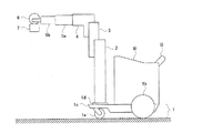
図1は、本発明に係る移動式X線装置の全体構成を示している。本発明に係る装置は、装置の基部にシャーシ1を備えている。シャーシ1は、2つの前輪1aおよび2つの後輪1bが備えられた基台1cを有している。シャーシ1は、装置を構成する他の各部を搭載している。シャーシ1は、支柱2を支持する構成である。
FIG. 1 shows the overall configuration of the mobile X-ray apparatus according to the present invention. The device according to the present invention includes a chassis 1 at the base of the device. The chassis 1 has a base 1c provided with two
シャーシ1には、本体部Bが備え付けられている。本体部Bには、電源装置や、バッテリー、操作パネル、放射線検出器を収納するホルダ等が備え付けられている。本体部Bには、装置を走行させるときに操作者が握るグリップGが備えられている。操作者がグリップGに力を加えれば、シャーシ1に備えられたアシスト機能が働き、操作者が与えた力を補助する構成となっている。これにより、操作者は、軽々と装置を移動させることができる。 The chassis 1 is provided with a main body portion B. The main body B is provided with a power supply device, a battery, an operation panel, a holder for accommodating a radiation detector, and the like. The main body B is provided with a grip G that the operator holds when running the device. When the operator applies a force to the grip G, the assist function provided in the chassis 1 works to assist the force given by the operator. As a result, the operator can easily move the device.
支柱2は、鉛直方向に伸びる部材であり、内部が中空になっている。この支柱2は、鉛直方向に伸びる軸周りに回転自在となっている。この支柱2は、手動で回転させることができる。支柱2は、後述のX線管6を昇降自在に支持する鉛直方向に伸びるとともに中空である。
The
中間材3は、支柱2を延伸するように設けられている鉛直方向に縦長の部材である。支柱2は、中間材3を昇降自在に支持する。支柱2には、中間材3を受ける鉛直方向に伸びる溝が設けられており、中間材3は、この溝に沿って鉛直方向に移動することができる。中間材3は、X線管6と支柱2とに挟まれる位置に設けられるとともにX線管6の昇降移動に伴って昇降移動する。
The
先端支柱4は、中間材3を更に延伸するように設けられているL形状の部材である。中間材3は、先端支柱4を昇降自在に支持する。先端支柱4は、互いに直交する2つの腕を有し、一方の腕は鉛直方向に伸びており、もう一方の腕は水平方向に伸びている。中間材3には、先端支柱4が有する鉛直方向の腕を受ける鉛直方向に伸びる溝が設けられており、先端支柱4は、この溝に沿って鉛直方向に移動することができる。
The tip support column 4 is an L-shaped member provided so as to further extend the
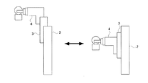
横支柱5a,5bは、水平方向に伸びる横長の部材である。先端支柱4が有する水平方向の腕、横支柱5a,横支柱5bは、この3つで入れ子式の伸縮構造となっている。図2の左側は、当該伸縮構造を最大に引き延ばした状態を示している。図2の右側は、当該伸縮構造を最小まで押し縮めた状態を示している。この伸縮機構は、手動で操作することができる。
The
X線管6は、X線を発生する装置である。X線管6は荷重物であり、相当の重さがある。X線管6は、横支柱5bにより支持されており、支柱2,中間材3,先端支柱4,横支柱5a,5bは、X線管6の荷重をシャーシ1に伝える構成となっている。X線管6の制御に関する回路は、本体部Bに収納されている。また、X線管6にはX線の広がりを制限するコリメータ7が付属されている。このコリメータ7は、X線管6の移動に追従して移動する。X線管6は、X線を照射する。
The
図3は、先端支柱4の昇降移動を説明している。図3左側は、先端支柱4を最も上方まで移動させた状態を表し、図3右側は、先端支柱4を最も下方まで移動させた状態を表している。先端支柱4を上下方向に移動させると、中間材3はこれに連動して移動する。すなわち、先端支柱4をある移動量だけ一方向に移動させると、中間材3は、その移動量の半分だけ同じ方向に移動する構成となっている。
FIG. 3 illustrates the vertical movement of the tip support column 4. The left side of FIG. 3 shows the state in which the tip support column 4 is moved to the uppermost position, and the right side of FIG. 3 shows the state in which the tip end support column 4 is moved to the lowest position. When the tip support column 4 is moved in the vertical direction, the
この様に、本発明の装置によれば、X線管6の縦移動は、支柱2,中間材3,先端支柱4から構成される機構が担当し、X線管6の横移動は、先端支柱4,横支柱5a,横支柱5bで構成される機構が担当する構成になっている。なお、X線管6の回転移動は、支柱2が担当する。X線管6を鉛直軸周りに回転させるような力を加えると、支柱2はシャーシ1に対して自転する。すると、中間材3,先端支柱4,横支柱5a,5bおよびX線管6が支柱2との位置関係を保った状態で追従して回転する。
As described above, according to the apparatus of the present invention, the vertical movement of the
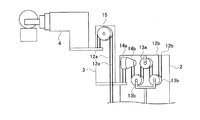
本発明において、特徴的なのは、X線管6の縦移動を実現する機構である。図4は、この機構について説明している。先端支柱4とシャーシに設けられた回転基台1dには、ワイヤの先端を固定する固定具が設けられている。この2つの固定具の間には、中間材ワイヤ23が設けられている。すなわち、中間材ワイヤ23の一端は、先端支柱4の固定具に固定され、他端は、回転基台1dの固定具に固定されている。中間材ワイヤ23は、中間材3に設けられている中間材プーリ15の上側に接するように巻き掛けられた格好で保持されている。中間材プーリ15は、中間材3にとっての定滑車となっている。
In the present invention, a feature is a mechanism that realizes vertical movement of the
この中間材ワイヤ23に係る機構について簡単に説明する。図4の状態の中間材3が上方に移動したとする。この場合、中間材プーリ15を基準として中間材ワイヤ23の動きを見ると、中間材ワイヤ23は、回転基台1d側に巻き取られる。すると、中間材プーリ15と先端支柱4との間の中間材ワイヤ23が短くなり、先端支柱4は、それに連れて上昇する。また、図4の状態の中間材3が下方に移動したとする。この場合、中間材プーリ15を基準として中間材ワイヤ23の動きを見ると、中間材ワイヤ23は、先端支柱4側に巻き取られる。すると、中間材プーリ15と先端支柱4との間の中間材ワイヤ23が長くなり、先端支柱4は、それに連れて下降する。中間材3がある長さだけ移動すると、中間材ワイヤ23はその長さの2倍だけ巻き取られるので、先端支柱4の移動距離も中間材3の移動距離の2倍となる。
The mechanism related to the
支柱2は、中空となっており、支柱2の内部空間には、種々の機構が備えられている。支柱の内部空間にとっての天井にあたる内面には、ワイヤの先端を固定する固定具が設けられている。同様に、中間材3にも固定具が設けられている。
The
支柱内には、巻き取りプーリ14aと螺旋プーリ14bとが備えられている。これらプーリ14a,14bは、支柱2にとっての定滑車となっており、回転軸を共有している。巻き取りプーリ14aは円柱形となっており、コイル状の溝が掘られている。一方、螺旋プーリ14bは、半径比が可変となっている輪軸を有する滑車であり、テーパ状となっている。巻き取りプーリ14aおよび螺旋プーリ14bには、ワイヤの先端を固定する固定具が設けられている。
A take-up
巻き取りプーリワイヤ12aは、一端が中間材3の固定具に固定され、他端が巻き取りプーリ14aの固定具に固定されている。巻き取りプーリワイヤ12aは巻き取りプーリ14aに巻きかけられた格好で保持されている。したがって、巻き取りプーリワイヤ12aは、巻き取りプーリワイヤ12aを起点として伸び、巻き取りプーリワイヤ12aの下側へ巻き出るように保持されている。
One end of the take-up
支柱内ワイヤ12bは、一端が螺旋プーリ14bの固定具に固定され、他端が支柱2内部の固定具に固定されている。支柱内ワイヤ12bは螺旋プーリ14bに巻きかけられた格好で保持されている。したがって、支柱内ワイヤ12bは、螺旋プーリ14bを起点として伸び、螺旋プーリ14bの下側へ巻き出るように保持されている。
One end of the
支柱2の内部において、支柱内プーリ14と支柱2の内面に設けられた固定具との間には、支柱2にとっての定滑車となっている中継プーリ13aが備えられている。中継プーリ13aは、支柱内ワイヤ12bを支持している。支柱内ワイヤ12bは、中継プーリ13aの上側に接するように巻き掛けられた格好で保持される。中継プーリ13aは、支柱内プーリ14から見て支柱内ワイヤ12bの他端側に設けられているとともに、支柱内ワイヤ12bを支持し、支柱2の内部に設けられる支柱2にとっての定滑車となっている。
Inside the
中継プーリ13aの両側のそれぞれには、中継プーリ13aに対して移動する動滑車13bが設けられている。支柱内ワイヤ12bは、2つの動滑車13bの下側に接するように動滑車13bに巻き掛けられている。
A moving
したがって、支柱内ワイヤ12bは、中間材3の固定具を始点として、支柱内プーリ14,動滑車13b,中継プーリ13a,動滑車13bに次々と巻き掛かって、支柱2の内面に設けられた固定具の終点まで伸びている。
Therefore, the
<機構の配置例>
図4に示す支柱2の内部は、動力の伝達が分かりやすいように作図がなされている。支柱2の内部の機構を図4に示すとおりにすると、支柱2の径を相当大きくしなければならなくなる。一方、図5は、図4と同様の機構をよりコンパクトに収めた配置例を示している。この様な配置例によれば、支柱2の径を小さくすることが可能である。<Example of mechanism layout>
The inside of the
図5左側は、当該配置例を支柱内プーリ14の回転軸方向から見た場合を示している。図4の説明では、支柱内プーリ14の回転軸が中継プーリ13aの回転軸と直交するように描かれているが、図5左側に示すように、互いの回転軸を一致させることもできる。また、図4の説明では、動滑車13bが回転軸と直交する方向に配列していたが、図5左側に示すように、互いの回転軸を一致させることもできる。図5右側は、当該配置例を支柱内プーリ14の回転軸の直交方向から見た場合を示している。
The left side of FIG. 5 shows a case where the arrangement example is viewed from the rotation axis direction of the
<バネ機構について>
続いて、本発明の特徴的な部分となっているバネ機構について説明する。バネ機構は、2つの動滑車13bを通じて支柱内ワイヤ12bを引き下げることにより、支柱内ワイヤ12bを支柱内プーリ14から引き取ろうとする力を発生させる。この力が中間材3の落下を引き留めることになる。バネ機構は、支柱内ワイヤ12bに張力を付与する構成であり、支柱2の内部に備えられている。<About the spring mechanism>
Subsequently, the spring mechanism, which is a characteristic part of the present invention, will be described. The spring mechanism pulls down the
バネ機構は、鉛直方向に直列に配列されたコイル状となっている2つの圧縮バネ8a,8bを備えている。この圧縮バネ8a,8bは、図4右側に示すように、径と長さの比が略1:4以下となっているのが望ましい。圧縮バネ8a,8bがこれ以上長いと、座屈を惹き起こしやすいからである。圧縮バネとは、引っ張りバネとは異なり、ある対象に圧縮されると反発力を付与するバネのことである。身近な圧縮バネとしては、乾電池ホルダに備えられた負極保持用のバネがある。バネ機構は、鉛直方向に直列に配列された複数の圧縮バネ8a,8b,中継バネ座9は、圧縮バネを連接する。
The spring mechanism includes two
2つの圧縮バネ8a,8bは、中心軸を同じくして鉛直方向に連接して設けられている。この2つの圧縮バネ8a,8bに挟まれる位置には、円盤状の中継バネ座9が設けられている。この中継バネ座9の構造について説明する。図6は、バネ機構の構造をより分かりやすく説明する概念図である。この図6は、圧縮バネ8aの内部が分かりやすいように、圧縮バネ8aおよびその周辺の部品の断面を示したものとなっている。中継バネ座9には、上下両側から異なる圧縮バネ8a,8bの端部がはめ込まれている。中継バネ座9には、圧縮バネ8a,8bを嵌合させる円柱形状の突起が上下に設けられており、圧縮バネ8aの両端のうち下側にある末端と、圧縮バネ8bの両端のうち上側にある先端は、それぞれに対応する突起にはまり込む。これにより圧縮バネ8a,8bは、中継バネ座9に連結する。また、中継バネ座9には、鉛直方向に伸びた貫通孔が設けられており、この貫通孔の内部には、後述のシャフト10が配置される。
The two
圧縮バネ8a,8bとこれらを中継する中継バネ座9は、これで一つの圧縮バネのように機能する。そこで、圧縮バネ8a,8bおよび中継バネ座9をバネユニットと呼ぶことにする。バネユニットの下部には、円板状の末端バネ座11が設けられている。末端バネ座11には、圧縮バネ8bを嵌合させる円柱形状の突起が上部に設けられており、バネユニットの両端のうち下側にある末端は、この突起にはまり込むことで末端バネ座11に連結する。また、末端バネ座11には、鉛直方向に伸びた貫通孔が設けられており、この貫通孔の内部には、後述のシャフト10が配置される。同様に、バネユニットの上部には、円板状の先端バネ座21が設けられている。先端バネ座21には、圧縮バネ8aを嵌合させる円柱形状の突起が下部に設けられており、バネユニットの両端のうち上側にある先端は、この突起にはまり込むことで先端バネ座21に連結する。また、先端バネ座21には、鉛直方向に伸びた貫通孔が設けられており、この貫通孔の内部には、後述のシャフト10が配置される。シャフト10は、複数の圧縮バネの内部を貫通するように設けられているとともに、圧縮バネ8a,8bが連接されることにより構成されるバネユニットの一端に固定され、中継バネ座9を昇降自在に支持する鉛直方向に伸びた部材である。また、先端バネ座21は、シャフト10をガイドする構成となっている。先端バネ座21は、バネ機構を構成するバネのうち支柱内プーリ14に近いものに連接するとともにシャフト10をガイドする構成である。
The compression springs 8a and 8b and the
支柱2の中空には、先端バネ座21を支持する隔壁22が設けられている。この隔壁22は、支柱の中空を上部と下部に分断するように設けられており、シャフト10を通過させる鉛直方向に伸びた貫通孔が設けられている。隔壁22は、支柱2の内壁に固定されており、先端バネ座21が支柱2内部を上方に移動することを阻止している。隔壁22は、本発明のユニット固定材に相当する。隔壁22は、バネユニットの他端を支柱2に固定する。
A
シャフト10は、バネユニットの下端を起点とし、コイル状となっているバネユニットの内部を貫通するように通過してバネユニットの上端から突き出して鉛直方向に伸びる棒状の構造であり、鉛直方向に伸びている。バネユニットの下端にあるシャフト10の先端には、ねじ山が切られており、ナットが螺合されている。このナットは末端バネ座11の下側に位置しておりシャフト10に支持される。ナットは、ナットの上部に位置する末端バネ座11が落下してしまうことを防いでいる。このナットは、バネユニットが分解してしまうことを抑制している。
The
バネユニットは、鉛直方向に伸縮自在となっている。バネユニットが伸縮すると、それに追従してシャフト10,末端バネ座11およびバネユニットを構成する中継バネ座9が鉛直方向に上下移動する。この際、シャフト10,末端バネ座11と中継バネ座9とは同方向に移動するわけであるが、中継バネ座9の移動量よりも末端バネ座11の移動量は大きくなる。バネの変位量は、末端に行くほど大きくなるからである。また、シャフト10と末端バネ座11は固定されているのでバネユニットを伸縮させても相対位置に変化はない。また、バネユニットが伸縮すると先端バネ座21は隔壁22に抑止されて移動しないが、先端バネ座21とシャフト10との相対位置は変化する。
The spring unit is stretchable in the vertical direction. When the spring unit expands and contracts, the
中継バネ座9の貫通孔には、シャフト10を滑らかに案内する目的で図示しないベアリングが設けられている。
A bearing (not shown) is provided in the through hole of the
シャフト10の両端のうち、バネユニットの上端から突き出している末端には、上述の動滑車13bを支持するアームAが固定された状態で設けられている。この図の場合アームAはU型をしている。アームAの各々の先端には、動滑車13bが備え付けられている。アームAは、シャフト10に固定されている。動滑車13bは、アームAに支持されるとともに、中継プーリ13aの両側に配置され、それぞれ支柱内ワイヤ12bに巻き掛けられている。
Of both ends of the
本明細書におけるバネ機構とは、アームA,圧縮バネ8a,8b,中継バネ座9,シャフト10,末端バネ座11,先端バネ座21,動滑車13bの複合体のことである。
The spring mechanism in the present specification is a composite of an arm A, compression springs 8a and 8b, a
本発明のバネ機構が支柱内ワイヤ12bに付与する力について説明する。バネユニットは、圧縮バネで構成されるので、先端バネ座21および末端バネ座11に対し互いを遠ざけようとする力を付与することになる。先端バネ座21は、支柱2内部を移動しないことからすると、バネユニットは、下降させようとする力をシャフト10に付与することになる。この力は、アームA先端の動滑車13bまで伝達される。こうして、支柱内ワイヤ12bには、ワイヤを押し下げようとする力が与えられる。すなわち、バネユニットが伸びようとする力が動滑車13bで生じている支柱内ワイヤ12bを押し下げようとする力を発生させていることになる。
The force applied to the
図7は、バネユニットが伸縮する様子を示している。図7左側は、バネユニットが最も伸びた状態を表している。このときのX線管6は、上方いっぱいまで移動された状態となり、これよりも上には動かない。この場合でも、バネユニットを構成する圧縮バネ8a,8bは、未だ伸びようとする力を残している。したがって、先端バネ座21および末端バネ座11に対し互いを遠ざけようとする力は、弱いながらも維持された状態となる。
FIG. 7 shows how the spring unit expands and contracts. The left side of FIG. 7 shows the state in which the spring unit is most extended. At this time, the
一方、図7右側は、バネユニットが最も縮んだ状態を表している。このときのX線管6は、下方いっぱいまで移動された状態となり、これよりも下には動かない。この場合でも、バネユニットを構成する圧縮バネ8a,8bは、最も圧縮される。したがって、先端バネ座21および末端バネ座11に対し互いを遠ざけようとする力は、最も強い状態となる。
On the other hand, the right side of FIG. 7 shows the state in which the spring unit is most contracted. At this time, the
この様にバネユニットの伸縮によりシャフト10に付与される力の強さは変わるので、支柱内ワイヤ12bを押し下げようとする力の強さも変わる。しかし、X線管6を操作する操作者は、この変化を感じることがない。支柱内ワイヤ12bを押し下げようとする力の変化は、螺旋を備える支柱内プーリ14により相殺されるからである。
Since the strength of the force applied to the
<本発明の効果>
続いて、本発明の効果について説明する。図8は、圧縮バネ8aが経年劣化等により断絶した場合を示している。圧縮バネ8aは断絶しても断片のそれぞれが伸びようとする。すると、断片同士が引っかかり合って、互いの伸長を阻害する。圧縮バネ8aが断絶する前と後で何が違うかといえば、コイル状となっている圧縮バネ8aが1ピッチ分だけ短くなったということである。したがってバネが断絶した場合はバネが1ピッチ分だけ短くなり、これによりX線管6もそれに相当する距離落下するが、際限なく落下すると言う事態は起きない。<Effect of the present invention>
Subsequently, the effect of the present invention will be described. FIG. 8 shows a case where the
このように、圧縮バネを図14の左側で説明したカウンターウェートの代わりに用いれば装置の安全性を保つのに役立つわけであるが、解決の難しい問題点がある。引っ張りバネとは異なり、圧縮バネは、ストロークの確保が難しいのである。引っ張りバネは、長いストロークを有する機構に適している。ストロークを長くしたければ、バネを長くすればいいのである。ところが、圧縮バネは、同じ原理でストロークを稼ぐことができない。圧縮バネには、座屈という特有の問題があるからである。 As described above, if the compression spring is used instead of the counter weight described on the left side of FIG. 14, it helps to maintain the safety of the device, but there is a problem that is difficult to solve. Unlike tension springs, compression springs have a difficult stroke. Tension springs are suitable for mechanisms with long strokes. If you want to make the stroke longer, you can make the spring longer. However, compression springs cannot earn strokes on the same principle. This is because compression springs have a unique problem of buckling.
圧縮バネは、長くなればなるほど、屈曲しやすくなる特性がある。圧縮バネは、バネの両側から圧力をかけるようなかたちで使用されるわけであるが、バネが長くなると、バネの中間がバネの延伸方向と直交する方向に逃げたがるようになる。結果としてバネは屈曲し、本来の機能を果たさない。 The longer the compression spring, the easier it is to bend. A compression spring is used in such a way that pressure is applied from both sides of the spring, but when the spring becomes long, the middle of the spring wants to escape in a direction orthogonal to the extension direction of the spring. As a result, the spring bends and does not perform its intended function.
そこで、本発明において考え出されたのが中継バネ座9である。これにより、圧縮バネを直列につなぎ合わせても圧縮バネが座屈しなくなる。すなわち、中継バネ座9は、シャフト10に案内される構成となっており、バネの延伸方向と直交する横方向に逃げ出すことがない。圧縮バネ8a,8bは、中継バネ座9により支持され、横方向に逃げ出すことができない。一方、個別の圧縮バネ8a,8bは、十分に短く、座屈することがない。結果としてバネは屈曲せず、本来の機能を果たすことになる。
Therefore, the
本発明は、上述の構成に限られず、下記のように変形実施することができる。 The present invention is not limited to the above configuration, and can be modified as follows.
(1)上述の実施例によれば、巻き取りプーリワイヤ12aおよび支柱内ワイヤ12bは、それぞれ1本しかなかったが、本発明の構成はこれに限られない。図9に示すように、巻き取りプーリワイヤ12aおよび支柱内ワイヤ12bを2重にすることができる。この様な構成とすることにより、仮に、巻き取りプーリワイヤ12aおよび支柱内ワイヤ12bの1本が断絶するようなことがあったとしても、断絶していないもう一本がX線管6を支持することでX線管6の落下を防ぐことができる。また、巻き取りプーリワイヤ12aおよび支柱内ワイヤ12bを3重以上とすることもできる。
(1) According to the above-described embodiment, there is only one take-up
同様に、上述の実施例によれば、中間材ワイヤ23は、1本しかなかったが、本発明の構成はこれに限られない。図9に示すように、中間材ワイヤ23を2重にすることができる。この様な構成とすることにより、仮に中間材ワイヤ23の1本が断絶するようなことがあったとしても、断絶していないもう一本がX線管6を支持することでX線管6の落下を防ぐことができる。また、中間材ワイヤ23を3重以上とすることもできる。
Similarly, according to the above-described embodiment, there is only one
なお、図9は、巻き取りプーリワイヤ12a、支柱内ワイヤ12bおよび中間材ワイヤ23が多重になっているが、どれかを選択して多重に構成することもできる。
In FIG. 9, the take-up
(2)上述の実施例によれば、支柱内ワイヤ12bの切断を感知する構成については言及が無かったが、図10に示すようにワイヤの張りを検出するセンサ31を設けるようにしても良い。センサ31は、押し下げようとする力を付与すると押し下がり、力の付与を解除するとひとりでに押し上がるような腕を有している。センサ31は、腕が押し下がっているときは、ON,押し上がっているときはOFFとなるような電子部品である。センサ31は、腕が支柱内ワイヤ12bに押し当てられるように支柱2の内部に装着され、腕が支柱内ワイヤ12bに押し下げられることでON状態となっている。なお、センサ31の腕の先端には、球形の補強材が設けられており、支柱内ワイヤ12bによりセンサ31の腕が摩耗するのを防いでいる。
(2) According to the above-described embodiment, there is no mention of a configuration for detecting the disconnection of the
支柱内ワイヤ12bが断絶すると、腕を押し下げていた力が消失するので、腕はひとりでに押し上がりセンサ31はOFFとなる。移動式X線装置は、この時点でセンサ31の出力に基づいてワイヤの切断を操作者に知らせる発報を実行する。このような変形例は、ワイヤが多重となっている図9のような構成に適している。すなわち、図9のような構成は、ワイヤが断絶してももう一本のワイヤにより正常な動作ができてしまう。しかしながら、これを放置していると、断絶したワイヤが絡まって支柱2内部の構造を破損させてしまうことも起こりえる。したがって、ワイヤの断絶はいち早く操作者に伝達した方がよい。なお、図9のようなワイヤが多重となっている場合は、2本の支柱内ワイヤ12bのそれぞれにセンサ31を設ける構成となる。
なお、本変形例におけるセンサ31は、腕が押し下がっているときはON,押し上がっているときはOFFとなるような電子部品となっていたが、これに変えて、腕が押し下がっているときはOFF,押し上がっているときはONとなるようなセンサ31を用いて本変形例を構成するようにしてもよい。When the
The
(3)実施例1では、2つの圧縮バネ8a,8bが連接してバネユニットが構成されていたが、3つ以上の圧縮バネを連接してバネユニットを構成するようにしてもよい。
(3) In the first embodiment, two
(4)実施例1では、2つの圧縮バネ8a,8bが連接してバネユニットが構成されていたが、1つの圧縮バネでも本発明を実現できる。図11は、当該変形例に係る装置を示している。この装置は、バネユニットに特徴がある。すなわち、バネユニットは、長い1本の圧縮バネで構成される。通常ならば、圧縮バネがここまで長いとすぐに座屈してしまうところであるが、本変形例では、これを抑える工夫がなされている。
(4) In the first embodiment, the two
本変形例の圧縮バネの中間には、中間連結具9aが固定されている。この中間連結具9aの構造について説明する。図12(a)は、バネ機構の構造をより分かりやすく説明する概念図である。この図12(a)は、圧縮バネ8の内部が分かりやすいように、圧縮バネ8およびその周辺の部品の断面を示したものとなっている。中間連結具9aは、円柱形をしており、側面には圧縮バネが嵌合する螺旋状の溝が刻まれている。また、中間連結具9aには、鉛直方向に伸びた貫通孔が設けられており、この貫通孔の内部には、シャフト10が配置される。中間連結具9aの貫通孔には、シャフト10を滑らかに案内する目的でベアリングが設けられている。中間連結具9aは、圧縮バネ8の中間に固定されている。シャフト10は、圧縮バネ8の内部を貫通するように設けられているとともに、圧縮バネ8の一端に固定され、中間連結具9aを昇降自在に支持する鉛直方向に伸びた部材である。
An
本発明は、1本の圧縮バネで上述と同様の効果を奏する構成となっている。中間連結具は、シャフトに案内される構成となっており、バネの延伸方向と直交する横方向に逃げ出すことがない。中間連結具により分断された圧縮バネの各部は、十分に短く、座屈することがない。 The present invention has a configuration in which one compression spring has the same effect as described above. The intermediate connector is configured to be guided by the shaft, and does not escape in the lateral direction orthogonal to the extension direction of the spring. Each part of the compression spring separated by the intermediate connector is short enough to prevent buckling.
(5)実施例1では2つの動滑車を有していたが、本発明はこの構成に限られない。動滑車は1つでもよいし、3つ以上であってもよい。 (5) Although the first embodiment has two moving pulleys, the present invention is not limited to this configuration. The number of moving pulleys may be one or three or more.
(6)実施例1には、螺旋プーリ14aおよび巻き取りプーリ14bの各々に固定する2本のワイヤが設けられていたが、本発明はこの構成に限られない。支柱の内部空間にとっての天井にあたる内面には、ワイヤの先端を固定する固定具が設けられている。同様に、中間材3にも固定具が設けられている。支柱内部の固定具と中間材3の固定具の間に、1本の支柱内ワイヤを設ける構成とすることもできる。
(6) In Example 1, two wires fixed to each of the
この場合の支柱内ワイヤは、支柱内プーリ14に巻き掛けられた格好で保持されている。したがって、支柱内ワイヤは、支柱内プーリ14の下側から巻き付いた後、支柱内プーリ14の下側へ巻き出るように保持されている。支柱内プーリ14は、巻き取りプーリ14bと螺旋プーリ14aとなっている部分との2つの部分が互いに固着して構成される。巻き取りプーリ14bの部分の中心軸が支柱内プーリ14の回転軸である。巻き取りプーリ14bの部分には、コイル状の溝が掘られており、溝はテーパ部まで続いている。螺旋プーリ14aの溝は、巻き取りプーリ14bの部分から離れるほど次第に曲率が大きくなるような螺旋状の溝が設けられており、螺旋プーリ14aを支柱内プーリ14の回転軸方向から眺めると、螺旋形状となっている。支柱内プーリ14は、支柱2にとっての定滑車となっている。支柱内プーリ14は、支柱内ワイヤを支持する。支柱内ワイヤは支柱内プーリ14の螺旋と円筒部の境の部分で固定される。
In this case, the wire inside the strut is held around the
(7)実施例1によれば、先端バネ座21は、単一の部材で構成されていたが、本発明はこの構成に限られない。図12(b)に示すように、先端バネ座21を隔壁22に連接される受部材21aとシャフト10を被覆するとともに受部材21aに下側に連接する被覆部材21bとで構成するようにしてもよい。受部材21aは、リング状の部材であり、中央にシャフト10を通過させる貫通孔が設けられている。被覆部材21bは、キノコ形状となっている部材であり、中央にシャフト10を貫通させる貫通孔が設けられている。被覆部材21bは、縦方向に移動するシャフト10の案内となっていてシャフト10が傾くのを防止する。先端バネ座21を本変形例のような構成とすることで、バネ8aの耐座屈性はさらに向上する。なお、被覆部材21bはバネ8aに嵌合している。
(7) According to the first embodiment, the
更に、先端バネ座21自体に自動調心機構を設けてもよい。このようにすると、シャフト10が仮に傾いたとしても、被覆部材21bにシャフト10からの大きな力がかかることがなく両者に摩擦が生じることがないのでシャフト10の移動がスムーズとなる。
Further, the
以上のように、本発明は、医用分野に適している。 As described above, the present invention is suitable for the medical field.
1 シャーシ
2 支柱
3 中間材
6 X線源(放射線源)
8a,8b 圧縮バネ
9 中継バネ座
12 支柱内ワイヤ
13a 中継プーリ
13b 動滑車
14 支柱内プーリ
15 中間材プーリ
21(21a、21b)先端バネ座
22 中間材ワイヤ
1
8a,
Claims (7)
前記バネ機構は、
(A)上端と下端とを有し、上端が前記支柱の内側で固定される圧縮バネと、
(B)一端が前記動滑車に接続されており、前記圧縮バネの上端を介して前記圧縮バネを貫通し、前記圧縮バネの下端に固定されるシャフトを備えることを特徴とする移動型放射線装置。 A radiation source for irradiating radiation, a support column extending in the vertical direction for supporting the radiation source so as to be able to move up and down, and a position sandwiched between the radiation source and the support column, and moving up and down as the radiation source moves up and down. Supports the intermediate member, the wire in the column whose one end is connected to the intermediate material, and the other end is connected to the inside of the column, and the wire in the column, and is provided inside the column. A pulley in the column which is a fixed pulley for the column, and a moving pulley which is provided on the other end side of the wire in the column when viewed from the pulley in the column and is wound around the wire in the column. In a mobile radiation device provided inside the strut with a spring mechanism for applying tension to the wire in the strut.
The spring mechanism
(A) A compression spring having an upper end and a lower end, and the upper end being fixed inside the support column .
(B ) A mobile radiation device having one end connected to the moving pulley, penetrating the compression spring through the upper end of the compression spring, and having a shaft fixed to the lower end of the compression spring. ..
前記バネ機構を構成する前記圧縮バネに連接するとともにシャフトをガイドする先端バネ座を備えることを特徴とする移動型放射線装置。 In the mobile radiation apparatus according to claim 1,
Mobile radiation device, characterized in that it comprises a tip spring seat for guiding the shaft as well as connected to the compression bar Ne constituting the spring mechanism.
先端バネ座が自動調心機構を備えていることを特徴とする移動型放射線装置。 In the mobile radiation apparatus according to claim 2 ,
A mobile radiation device characterized in that the tip spring seat is equipped with an automatic centering mechanism.
一端が前記放射線源に接続されているとともに、他端が前記支柱あるいはそれが設置される基台に接続される中間材ワイヤと、前記中間材ワイヤを支持するとともに、前記中間材にとっての定滑車となっている中間材プーリを備えることを特徴とする移動型放射線撮影装置。 In the mobile radiography apparatus according to claim 1 ,
One end is connected to the radiation source, and the other end supports the intermediate material wire connected to the support column or the base on which the intermediate material wire is installed, and the intermediate material wire, and a fixed pulley for the intermediate material. A mobile radiography apparatus characterized by being provided with an intermediate material pulley.
前記中間材ワイヤが多重となっていることを特徴とする移動型放射線装置。 In the mobile radiation apparatus according to claim 4 ,
A mobile radiation device characterized in that the intermediate material wires are multiplexed.
前記支柱内ワイヤが多重となっていることを特徴とする移動型放射線装置。 In the mobile radiation apparatus according to claim 1 ,
A mobile radiation device characterized in that the wires in the columns are multiplex.
前記支柱内ワイヤの切断を感知するセンサを備えることを特徴とする移動型放射線装置。 In the mobile radiation apparatus according to claim 1 ,
A mobile radiation device comprising a sensor that detects a break in a wire in a column.
Applications Claiming Priority (1)
| Application Number | Priority Date | Filing Date | Title |
|---|---|---|---|
| PCT/JP2016/056296 WO2017149672A1 (en) | 2016-03-01 | 2016-03-01 | Moving-type radiation device |
Publications (2)
| Publication Number | Publication Date |
|---|---|
| JPWO2017149672A1 JPWO2017149672A1 (en) | 2018-12-27 |
| JP6766864B2 true JP6766864B2 (en) | 2020-10-14 |
Family
ID=59743640
Family Applications (1)
| Application Number | Title | Priority Date | Filing Date |
|---|---|---|---|
| JP2018502920A Active JP6766864B2 (en) | 2016-03-01 | 2016-03-01 | Mobile radiation device |
Country Status (5)
| Country | Link |
|---|---|
| US (1) | US10674978B2 (en) |
| EP (1) | EP3424426A4 (en) |
| JP (1) | JP6766864B2 (en) |
| CN (1) | CN108778132A (en) |
| WO (1) | WO2017149672A1 (en) |
Families Citing this family (7)
| Publication number | Priority date | Publication date | Assignee | Title |
|---|---|---|---|---|
| CN110213993B (en) | 2017-01-18 | 2023-05-16 | 株式会社岛津制作所 | X-ray device for inspection |
| US11712212B2 (en) | 2017-07-28 | 2023-08-01 | Cathy J. Grinham | Mobility apparatus for radiographic appliance |
| US11040734B2 (en) * | 2017-07-28 | 2021-06-22 | Cathy J. Grinham | Mobility apparatus for radiographic appliance |
| US11090015B2 (en) | 2017-10-03 | 2021-08-17 | Shimadzu Corporation | Diagnostic X-ray apparatus |
| DE102019130562B4 (en) * | 2018-11-14 | 2024-04-04 | Ewellix AB | Telescopic lifting unit |
| CN109626260B (en) * | 2018-12-18 | 2021-08-03 | 上海联影医疗科技股份有限公司 | Cross arm lifting assembly and movable radiation device |
| KR102468321B1 (en) * | 2021-03-29 | 2022-11-17 | (주)디알젬 | Tube drop preventing structure of X-ray apparatus |
Family Cites Families (30)
| Publication number | Priority date | Publication date | Assignee | Title |
|---|---|---|---|---|
| JPH02159264A (en) * | 1988-12-13 | 1990-06-19 | Hitachi Medical Corp | Operation safety apparatus of boom in x-ray imaging apparatus |
| JPH04122243A (en) * | 1990-09-14 | 1992-04-22 | Hitachi Medical Corp | Mobile x-ray device |
| US5283823A (en) * | 1991-11-27 | 1994-02-01 | X-Cel X-Ray Corporation | Portable radiographic device |
| JPH08200206A (en) * | 1995-01-27 | 1996-08-06 | Hisaka Works Ltd | Spring type actuator |
| JPH10288234A (en) * | 1997-04-15 | 1998-10-27 | Mitsubishi Heavy Ind Ltd | Vertical base isolation device |
| JP2002155979A (en) * | 2000-11-17 | 2002-05-31 | Fanuc Ltd | Spring device |
| DE20204321U1 (en) | 2002-03-19 | 2002-05-29 | Leica Microsystems | spring element |
| JP4133041B2 (en) | 2002-07-02 | 2008-08-13 | 株式会社日立メディコ | Mobile X-ray device |
| JP2005227717A (en) * | 2004-02-16 | 2005-08-25 | Fuji Photo Film Co Ltd | Fixing structure for image forming apparatus |
| US7497625B2 (en) | 2004-06-08 | 2009-03-03 | General Electric Company | Systems, methods and apparatus of an extending column |
| JP4743436B2 (en) * | 2007-01-29 | 2011-08-10 | 株式会社島津製作所 | Ceiling traveling X-ray tube suspension |
| FI20075182L (en) * | 2007-03-20 | 2008-11-10 | Planmeca Oy | Panoramic X-ray machine |
| JP4872744B2 (en) * | 2007-03-26 | 2012-02-08 | 株式会社島津製作所 | Suspended cage, X-ray imaging apparatus, and portable traveling X-ray imaging apparatus |
| JP4382852B2 (en) * | 2008-01-24 | 2009-12-16 | カルソニックカンセイ株式会社 | Vane compressor |
| JP2009201844A (en) * | 2008-02-29 | 2009-09-10 | Toshiba Medical Supply Co Ltd | Portable x-ray diagnostic system |
| JP5508883B2 (en) * | 2010-02-05 | 2014-06-04 | カヤバ システム マシナリー株式会社 | Pressure relief valve and seismic damper |
| US20110249806A1 (en) | 2010-04-13 | 2011-10-13 | Wendlandt William C | Mobile radiography unit having collapsible support column |
| US8568028B2 (en) | 2010-04-13 | 2013-10-29 | Carestream Health, Inc. | Mobile radiography unit having collapsible support column |
| US8672543B2 (en) | 2010-04-13 | 2014-03-18 | Carestream Health, Inc. | Counterweight for mobile x-ray device |
| US8465203B2 (en) * | 2011-03-02 | 2013-06-18 | General Electric Company | Brake systems for C-arm positioning devices, apparatus containing the same and methods for using such systems |
| CN102172669B (en) * | 2011-03-14 | 2013-06-05 | 江苏恒力组合机床有限公司 | Self-compensating servo wiring device for water tank type wire drawing machine |
| JP6238611B2 (en) * | 2012-09-28 | 2017-11-29 | キヤノン株式会社 | Mobile radiography apparatus, radiography system, and control method |
| JP2014073321A (en) * | 2012-10-05 | 2014-04-24 | Canon Inc | Mobile x-ray imaging apparatus |
| JP2014073322A (en) * | 2012-10-05 | 2014-04-24 | Canon Inc | Radiation generator apparatus |
| JP6222960B2 (en) * | 2012-11-12 | 2017-11-01 | キヤノン株式会社 | Radiation generating apparatus and radiation imaging apparatus |
| JP6065248B2 (en) * | 2013-02-27 | 2017-01-25 | 株式会社島津製作所 | X-ray equipment |
| JP6351716B2 (en) | 2013-07-04 | 2018-07-04 | ソシエダッド・エスパニョーラ・デ・エレクトロメディシナ・イ・カリダッド・ソシエダッド・アノニマSociedad Espanola De Electromedicina Y Calidad,S.A. | Mobile X-ray device with telescopic support |
| WO2016064993A1 (en) * | 2014-10-22 | 2016-04-28 | Carestream Health, Inc. | Mobile radiographic imaging apparatus |
| JP6066388B1 (en) * | 2015-11-26 | 2017-01-25 | 富士フイルム株式会社 | Radiation irradiation equipment |
| US11051775B2 (en) * | 2018-05-22 | 2021-07-06 | Carestream Health, Inc. | Collapsible column movement apparatus for mobile x-ray device |
-
2016
- 2016-03-01 EP EP16892516.2A patent/EP3424426A4/en not_active Withdrawn
- 2016-03-01 WO PCT/JP2016/056296 patent/WO2017149672A1/en active Application Filing
- 2016-03-01 CN CN201680083072.4A patent/CN108778132A/en active Pending
- 2016-03-01 JP JP2018502920A patent/JP6766864B2/en active Active
- 2016-03-01 US US16/081,284 patent/US10674978B2/en active Active
Also Published As
| Publication number | Publication date |
|---|---|
| EP3424426A4 (en) | 2019-03-27 |
| US10674978B2 (en) | 2020-06-09 |
| US20190069860A1 (en) | 2019-03-07 |
| EP3424426A1 (en) | 2019-01-09 |
| JPWO2017149672A1 (en) | 2018-12-27 |
| CN108778132A (en) | 2018-11-09 |
| WO2017149672A1 (en) | 2017-09-08 |
Similar Documents
| Publication | Publication Date | Title |
|---|---|---|
| JP6766864B2 (en) | Mobile radiation device | |
| EP3526379B1 (en) | Braiding machine and methods of use | |
| EP3695037B1 (en) | Braiding machine and methods of use | |
| JP4133041B2 (en) | Mobile X-ray device | |
| KR102541403B1 (en) | X-ray imaging apparatus | |
| EP3311746B1 (en) | Mobile x-ray imaging apparatus | |
| JP6769496B2 (en) | Mobile radiography device | |
| US10575813B2 (en) | Moving type radiation device | |
| EP3378350B1 (en) | Telescopic column with internal cable | |
| JP2008013046A (en) | Tension balancer for overhead wire | |
| KR101690461B1 (en) | Ceiling type x-ray photographing apparatus | |
| JP6828828B2 (en) | Diagnostic X-ray equipment | |
| JP4534824B2 (en) | X-ray imaging apparatus suspension apparatus and mobile X-ray imaging apparatus equipped with X-ray imaging apparatus suspension apparatus | |
| JP6806271B2 (en) | X-ray equipment | |
| JP6881672B2 (en) | Mobile radiography device | |
| JP2018034933A (en) | Object moving device and walking support device comprising same | |
| JP2009039283A (en) | Walking support apparatus | |
| JP2009039273A (en) | Walking support apparatus |
Legal Events
| Date | Code | Title | Description |
|---|---|---|---|
| A621 | Written request for application examination |
Free format text: JAPANESE INTERMEDIATE CODE: A621 Effective date: 20180831 |
|
| A131 | Notification of reasons for refusal |
Free format text: JAPANESE INTERMEDIATE CODE: A131 Effective date: 20190604 |
|
| A601 | Written request for extension of time |
Free format text: JAPANESE INTERMEDIATE CODE: A601 Effective date: 20190731 |
|
| A521 | Written amendment |
Free format text: JAPANESE INTERMEDIATE CODE: A523 Effective date: 20190917 |
|
| A131 | Notification of reasons for refusal |
Free format text: JAPANESE INTERMEDIATE CODE: A131 Effective date: 20200204 |
|
| A521 | Written amendment |
Free format text: JAPANESE INTERMEDIATE CODE: A523 Effective date: 20200331 |
|
| TRDD | Decision of grant or rejection written | ||
| A01 | Written decision to grant a patent or to grant a registration (utility model) |
Free format text: JAPANESE INTERMEDIATE CODE: A01 Effective date: 20200818 |
|
| A61 | First payment of annual fees (during grant procedure) |
Free format text: JAPANESE INTERMEDIATE CODE: A61 Effective date: 20200831 |
|
| R151 | Written notification of patent or utility model registration |
Ref document number: 6766864 Country of ref document: JP Free format text: JAPANESE INTERMEDIATE CODE: R151 |