JP6758876B2 - Modeling control device, its method and program - Google Patents
Modeling control device, its method and program Download PDFInfo
- Publication number
- JP6758876B2 JP6758876B2 JP2016069176A JP2016069176A JP6758876B2 JP 6758876 B2 JP6758876 B2 JP 6758876B2 JP 2016069176 A JP2016069176 A JP 2016069176A JP 2016069176 A JP2016069176 A JP 2016069176A JP 6758876 B2 JP6758876 B2 JP 6758876B2
- Authority
- JP
- Japan
- Prior art keywords
- modeling
- modeled object
- modeled
- dimensional space
- model
- Prior art date
- Legal status (The legal status is an assumption and is not a legal conclusion. Google has not performed a legal analysis and makes no representation as to the accuracy of the status listed.)
- Active
Links
Images


Classifications
-
- G—PHYSICS
- G05—CONTROLLING; REGULATING
- G05B—CONTROL OR REGULATING SYSTEMS IN GENERAL; FUNCTIONAL ELEMENTS OF SUCH SYSTEMS; MONITORING OR TESTING ARRANGEMENTS FOR SUCH SYSTEMS OR ELEMENTS
- G05B15/00—Systems controlled by a computer
- G05B15/02—Systems controlled by a computer electric
-
- B—PERFORMING OPERATIONS; TRANSPORTING
- B33—ADDITIVE MANUFACTURING TECHNOLOGY
- B33Y—ADDITIVE MANUFACTURING, i.e. MANUFACTURING OF THREE-DIMENSIONAL [3-D] OBJECTS BY ADDITIVE DEPOSITION, ADDITIVE AGGLOMERATION OR ADDITIVE LAYERING, e.g. BY 3-D PRINTING, STEREOLITHOGRAPHY OR SELECTIVE LASER SINTERING
- B33Y30/00—Apparatus for additive manufacturing; Details thereof or accessories therefor
-
- B—PERFORMING OPERATIONS; TRANSPORTING
- B29—WORKING OF PLASTICS; WORKING OF SUBSTANCES IN A PLASTIC STATE IN GENERAL
- B29C—SHAPING OR JOINING OF PLASTICS; SHAPING OF MATERIAL IN A PLASTIC STATE, NOT OTHERWISE PROVIDED FOR; AFTER-TREATMENT OF THE SHAPED PRODUCTS, e.g. REPAIRING
- B29C64/00—Additive manufacturing, i.e. manufacturing of three-dimensional [3D] objects by additive deposition, additive agglomeration or additive layering, e.g. by 3D printing, stereolithography or selective laser sintering
- B29C64/30—Auxiliary operations or equipment
- B29C64/386—Data acquisition or data processing for additive manufacturing
- B29C64/393—Data acquisition or data processing for additive manufacturing for controlling or regulating additive manufacturing processes
-
- B—PERFORMING OPERATIONS; TRANSPORTING
- B33—ADDITIVE MANUFACTURING TECHNOLOGY
- B33Y—ADDITIVE MANUFACTURING, i.e. MANUFACTURING OF THREE-DIMENSIONAL [3-D] OBJECTS BY ADDITIVE DEPOSITION, ADDITIVE AGGLOMERATION OR ADDITIVE LAYERING, e.g. BY 3-D PRINTING, STEREOLITHOGRAPHY OR SELECTIVE LASER SINTERING
- B33Y50/00—Data acquisition or data processing for additive manufacturing
- B33Y50/02—Data acquisition or data processing for additive manufacturing for controlling or regulating additive manufacturing processes
-
- G—PHYSICS
- G05—CONTROLLING; REGULATING
- G05B—CONTROL OR REGULATING SYSTEMS IN GENERAL; FUNCTIONAL ELEMENTS OF SUCH SYSTEMS; MONITORING OR TESTING ARRANGEMENTS FOR SUCH SYSTEMS OR ELEMENTS
- G05B19/00—Programme-control systems
- G05B19/02—Programme-control systems electric
- G05B19/18—Numerical control [NC], i.e. automatically operating machines, in particular machine tools, e.g. in a manufacturing environment, so as to execute positioning, movement or co-ordinated operations by means of programme data in numerical form
- G05B19/4097—Numerical control [NC], i.e. automatically operating machines, in particular machine tools, e.g. in a manufacturing environment, so as to execute positioning, movement or co-ordinated operations by means of programme data in numerical form characterised by using design data to control NC machines, e.g. CAD/CAM
- G05B19/4099—Surface or curve machining, making 3D objects, e.g. desktop manufacturing
-
- G—PHYSICS
- G05—CONTROLLING; REGULATING
- G05B—CONTROL OR REGULATING SYSTEMS IN GENERAL; FUNCTIONAL ELEMENTS OF SUCH SYSTEMS; MONITORING OR TESTING ARRANGEMENTS FOR SUCH SYSTEMS OR ELEMENTS
- G05B2219/00—Program-control systems
- G05B2219/30—Nc systems
- G05B2219/49—Nc machine tool, till multiple
- G05B2219/49023—3-D printing, layer of powder, add drops of binder in layer, new powder
Description
三次元状の造形物を、造形材を用いて造形する技術に関する。 It relates to a technique for modeling a three-dimensional model using a modeling material.
近年、三次元状の造形物を造形するための造形装置、いわゆる3Dプリンターがひろく用いられるようになってきている。 In recent years, a so-called 3D printer, which is a modeling device for modeling a three-dimensional modeled object, has been widely used.
特許文献1には、造形装置に対して造形指示を行うコンピューター(PC:Personal Computer)において、造形対象となる複数のオブジェクト同士を近接させて造形することで造形時間などを低減するための技術が開示されている。具体的には、複数のモデルデータとそれらの造形のために設定されたパラメーターに基づき、造形前に、それらをまとめて造形する場合の配置を決定している。
PCにおいて、造形指示前ならば、特許文献1のように、複数のモデルデータをまとめて造形するような指示が可能であった。
Before the modeling instruction, it was possible to instruct the PC to collectively model a plurality of model data as in
しかしながら、あるモデルデータに基づく造形指示を行った後、造形装置で造形中のオブジェクトに関連するオブジェクトを造形したくなった場合には、該造形処理の完了後に再度、造形指示する必要があった。 However, if it is desired to model an object related to the object being modeled by the modeling device after issuing a modeling instruction based on a certain model data, it is necessary to perform the modeling instruction again after the completion of the modeling process. ..
本発明では、造形装置での造形処理の途中で、追加でオブジェクトを造形指示するための手法を提供することを目的とする。 An object of the present invention is to provide a method for additionally instructing modeling of an object in the middle of a modeling process by a modeling apparatus.
本発明は、3次元の造形物を造形する造形部での造形処理を制御する造形制御装置であって、前記造形部での第1の造形物のための造形処理が完了するまでの処理時間を計算する計算手段と、前記造形部での第1の造形物のための造形処理の間に、該第1の造形物とは異なる第2の造形物の造形の指示と、該第2の造形物に対応する造形データを受け付ける受信手段と、前記造形部の造形物を造形可能な第1の立体的なスペースと、該第1の立体的なスペース内の前記第1の造形物の造形に必要となる第2の立体的なスペースとから、前記造形部において追加での造形物の造形が可能となる第3の立体的なスペースを特定する特定手段と、前記第2の造形物が、前記第3の立体的なスペース内で造形が可能か否かを判定する判定手段と、前記第3の立体的なスペース内で前記第2の造形物が造形できると判定された場合に、前記第1の造形物の造形のための造形制御コマンドに加えて、前記第3の立体的なスペース内に前記第2の造形物を造形するための前記造形データに基づく造形制御コマンドを、前記造形部に対して指示する指示手段と、を有し、前記計算手段は、造形中の第1の造形物に加えて前記判定手段で造形が可能と判断された第2の造形物の造形処理がともに完了するまでの処理時間を、さらに計算する、ことを特徴とする。 The present invention is a modeling control device that controls a modeling process in a modeling unit that models a three-dimensional modeled object, and the processing time until the modeling process for the first modeled object in the modeling unit is completed. Between the calculation means for calculating the above and the modeling process for the first modeled object in the modeling unit, an instruction for modeling a second modeled object different from the first modeled object, and the second A receiving means for receiving modeling data corresponding to a modeled object, a first three-dimensional space in which the modeled object of the modeling unit can be modeled, and modeling of the first modeled object in the first three-dimensional space. From the second three-dimensional space required for the above, the specific means for specifying the third three-dimensional space that enables the additional modeling of the modeled object in the modeling unit, and the second modeled object , A determination means for determining whether or not modeling is possible in the third three-dimensional space, and when it is determined that the second modeled object can be modeled in the third three-dimensional space. In addition to the modeling control command for modeling the first modeled object, the modeling control command based on the modeling data for modeling the second modeled object in the third three-dimensional space is given. comprising an instruction unit that instructs the shaping part, wherein the calculating means is shaped in a second shaped article is determined that can be shaped in front Symbol judging means in addition to the first molded article in molding treatment together processing time to complete, to further calculate, characterized in that.
本発明によれば、造形装置で造形処理の途中で、追加でオブジェクトを造形指示することができる。 According to the present invention, an object can be additionally instructed to be modeled during the modeling process by the modeling apparatus.
以下、本発明を実施するための最良の形態について図面を用いて説明する。 Hereinafter, the best mode for carrying out the present invention will be described with reference to the drawings.
本発明は、造形装置でのオブジェクトの造形処理の途中で、該造形装置に対して、追加で別のオブジェクトを造形指示し、それら複数の造形物を同時に造形していく方法を「合流造形」と呼び、その合流造形の実現方法について提案する。 In the present invention, a method of instructing the modeling device to additionally model another object in the middle of the modeling process of the object by the modeling device and simultaneously modeling the plurality of modeled objects is "merging modeling". We propose a method to realize the merged modeling.
(実施例1)
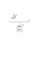
図1は、本発明におけるシステム構成の例を示す。
(Example 1)
FIG. 1 shows an example of a system configuration in the present invention.
LAN(Local Area Network)などのネットワーク101を介して、PC103及び造形装置102は接続されている。
The PC 103 and the
PC103は、造形装置に対して造形対象のオブジェクトを造形するための造形データを送信する。造形装置102は、造形データを受信して3次元のオブジェクトの造形のための造形処理を実行する。システム内には、複数の造形装置が存在してもよく、造形装置を利用するユーザーは、それら複数の造形装置から任意に造形処理を実行したい装置を選択できる。
The PC 103 transmits modeling data for modeling an object to be modeled to the modeling device. The
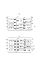
図2は、本発明に係る装置のハードウェア構成の例を示す。図2(a)は、PC103などの情報処理装置の構成を示す。図2(b)は、造形装置102の構成を示す。
FIG. 2 shows an example of the hardware configuration of the device according to the present invention. FIG. 2A shows the configuration of an information processing device such as a PC 103. FIG. 2B shows the configuration of the
図2(a)で示す情報処理装置において、CPU201は、ROM202あるいは外部メモリ211に記憶されたアプリケーションプログラムや本発明に係る造形制御のためのプログラム等に基づいて処理を実行し、システムバス212に接続される各デバイスを総括的に制御する。また、CPU201は、ディスプレイ209上の不図示のマウスカーソル等で指示されたコマンドに基づいて登録された種々のアプリケーションウィンドウを開き、種々のデータ処理を実行する。
In the information processing apparatus shown in FIG. 2A, the
RAM202は、CPU201の主メモリ、ワークエリア等として機能する。ROM203は、基本I/Oプログラム等の記憶領域として機能する読み出し専用のメモリである。このROM203あるいは外部メモリ211には、CPU201の制御プログラムであるオペレーティングシステム(以下OS)等が記憶される。さらにROM203あるいは外部メモリ210には上記アプリケーションプログラム等に基づく処理の際に使用するファイルやその他各種データを記憶する。
The
ネットワークI/F(インターフェース)204は、ネットワーク101へ接続しネットワーク通信を行う。入力I/F205は、キーボード206やマウス等のポインティングデバイス207からの入力を制御する。ディスプレイI/F208は、ディスプレイ209の表示を制御する。外部メモリI/F210は、ハードディスク(HD)等の外部メモリ211とのアクセスを制御する。
The network I / F (interface) 204 connects to the
外部メモリ211は、ブートプログラム、各種のアプリケーション、本発明に係る造形制御のためのプログラム、ユーザーファイル、編集ファイル等を記憶する。コンピューター103は、CPU201がROM203や外部メモリ211に書き込まれた基本I/OプログラムおよびOSを実行している状態で動作する。基本I/OプログラムはROM203に書き込まれており、OSはROM203または外部メモリ210に書き込まれている。そしてコンピューターの電源がONされたときに、基本I/Oプログラム中のイニシャルプログラムロード機能により、ROM203または外部メモリ211からOSがRAM202に書き込まれ、OSの動作が開始される。
The
図2(b)で示す造形装置102において、ネットワークI/F251は、ネットワーク101へ接続しネットワーク通信を行う。これ以外にも、USB(Universal Serial Bus)のインターフェースを備えていてもよい。造形装置102は、ネットワークI/F251や不図示のUSB I/Fを介して、造形指示と造形対象のオブジェクトに対応ずる造形データを受付けることになる。
In the
CPU252は、アプリケーションプログラムや本発明に係る造形制御のためのプログラム等に基づいてシステムバス265に接続される各デバイスを総括的に制御する。とくに、コントローラ263を介して造形部264にオブジェクト造形のための制御信号などを出力する。なお、制御プログラムはROM254や外部メモリ262等に記憶される。CPU252はネットワークI/F251を介してコンピューターとの通信処理が可能となっており、造形装置102内の情報等をコンピューター103に通知可能なように構成されている。さらにCPU252はROM254あるいは外部メモリ262に記憶されたアプリケーションプログラム等に基づいて処理を実行する。
The
RAM253は、CPU252の主メモリ、ワークエリア等として機能し、図示しない増設ポートに接続されるオプションRAMによりメモリ容量を拡張することができるように構成されている。なお、RAM253は、出力情報展開領域、環境データ格納領域、NVRAM等に用いられる。ROM254あるいは外部メモリ262には、CPU252の制御プログラムやアプリケーションプログラムおよび上記出力情報を生成する際に使用するフォントデータ、造形装置102上で利用される情報等が記憶される。またROM254あるいは外部メモリ262には、造形装置102のアプリケーションインストール時にアプリケーションが一時的に格納される。
The RAM 253 functions as a main memory, a work area, and the like of the
操作部I/F255は、操作部256との間のインターフェースをつかさどり、表示すべき画像データを操作部256に対して出力する。また、ユーザーが操作部256を介して入力した情報の受信も行う。操作部256は、操作のためのスイッチおよびLED表示器等が配されている操作パネル等に相当する。プリンターI/F257は、プリンター258(プリンターエンジン)に出力情報としての画像信号を出力する。センサーI/F259は、センサー260(温度センサー、振動センサー、物体識別センサーなど)からの入力情報として信号を受信する。さらに、センサー260には、造形装置102にセットされる造形材供給部における造形に用いる消耗材の残量を検知するセンサーもある。
The operation unit I /
なお、液体、粉末などの消耗材は、造形材供給部に対して消耗材を含むカートリッジを着脱することで供給する形式であってもよい。または、造形材供給部に対して消耗材を専用のボトルなどから手動で補給する形式もよい。 The consumable material such as liquid or powder may be supplied by attaching / detaching a cartridge containing the consumable material to the modeling material supply unit. Alternatively, a form in which consumables are manually supplied to the modeling material supply unit from a dedicated bottle or the like may be used.
外部メモリI/F(メモリコントローラ)261は、ハードディスク(HD)、ICカード等の外部メモリ262へのアクセスを制御する。また、前述した外部メモリは1個に限らず、少なくとも1個以上備え、内蔵フォントに加えてオプションフォントカード、言語系の異なるプリンター制御言語を解釈するプログラムを格納した外部メモリを複数接続できるように構成されていてもよい。さらに、図示しないNVRAMを有し、操作部256からのプリンターモード設定情報を記憶するようにしてもよい。
The external memory I / F (memory controller) 261 controls access to the
コントローラ263は、受信した3次元オブジェクト造形のための信号をもとに、造形部264に造形処理を実行させる。造形部264には、造形方式によって異なるが、造形材を積層するための設備や、造形物が造形されるステージ、造形材を硬化させるためのエネルギー源である装置などで構成される。造形方式に応じて造形部264が備える構成は異なり、その具体例については、図3で後述する。
The
なお、不図示だが、造形装置102にはオプション機器として、造形方式に応じて必要となる付帯設備や、カメラやICカードリーダー等の3Dプリンターの機能及び機構を拡張する周辺機器などがある。付帯設備の例として、インクジェット方式の場合に粉末対策として必要な装置や、光造形(SLA)の場合に必要となる洗浄装置などがある。
Although not shown, the
図3は、本発明が適用できる積層造形(“Additive Manufacturing”)を行う造形方式の例を示す。 FIG. 3 shows an example of a modeling method for performing laminated modeling (“Adaptive Manufacturing”) to which the present invention can be applied.
図3(a−1)は、材料シート積層方式による3次元造形物の造形方法を示す図である。 FIG. 3A-1 is a diagram showing a method of modeling a three-dimensional modeled object by a material sheet laminating method.
この方式では、造形部264において、ステージ301上への材料シート310を積層と、エネルギー源302からのエネルギー(光、熱など)の放射と、を繰り返すことで、造形物304を徐々に積層造形していく。図3(a−2)は、1枚の材料シート310を図示している。材料シート310は、造形材を含む構造材312とサポート材311とからなる。構造材312は、エネルギー源302からのエネルギーを受けて、前後に積層される材料シートの構造材部分に溶着される。これによって、積層造形物304が完成していくことになる。なお、サポート材311は積層造形物304に対して溶着されることはなく、積層造形物304のサポート303として、ステージ301上に積層されていく。例えば、このサポート303は、水溶性であって、積層造形物304を取り出す際にはサポート303部分に対して水をかけることで除去することが可能である。
In this method, in the
材料シート積層方式においては、造形中のオブジェクトに対応する材料シート310のサポート材311部分に、追加で造形されるオブジェクトに対応する構造材312を形成することで、本発明が提案する合流造形が実現できる。
In the material sheet laminating method, the confluence molding proposed by the present invention is achieved by forming the
図3(b)は、光造形方式による3次元造形物の積層造形の方法を示す図である。 FIG. 3B is a diagram showing a method of laminating modeling of a three-dimensional modeled object by a stereolithography method.
この方式では、造形部264において、ステージ301上への造形材(紫外線硬化樹脂など)の積層と、エネルギー源302からのエネルギー(レーザーからの紫外線など)の放射と、を繰り返すことで、造形物304を徐々に積層造形していく。ここでは、紫外線が当たらなかった部分については、硬化せずにステージ301上に残ることになる。よって、硬化しなかった造形材はそのまま積層造形物304のサポートとなり、造形処理の完了時には、その部分を除くことで造形物のみが取り出せる。
In this method, in the
図3(b)で示す造形方式においては、エネルギーの照射位置として、造形中のオブジェクトに対応する座標情報に、追加で造形されるオブジェクトに対応する座標情報を追加していくことで、本発明が提案する合流造形が実現できる。 In the modeling method shown in FIG. 3 (b), the present invention is performed by adding the coordinate information corresponding to the object to be additionally modeled to the coordinate information corresponding to the object being modeled as the energy irradiation position. The merged modeling proposed by is realized.
図4は、本発明に係る装置のソフトウェアのモジュール構成例を示す。 FIG. 4 shows an example of a module configuration of software of the device according to the present invention.
本図は、本発明の説明のための概念図であって、各モジュールは、前述した造形制御のためのプログラムをCPU201、またはCPU252が実行することで実現される処理の主体となるよう例示したものである。
This figure is a conceptual diagram for explaining the present invention, and each module is illustrated so as to be a main body of processing realized by executing the above-mentioned program for modeling control by
受信部401は、合流造形の指示や合流造形の対象となる造形データを受け付ける。造形データには、3次元のモデルデータに対応するSTL(Standard Triangulated Language)形式のデータファイルなどが含まれる。造形データとしては、3次元のオブジェクトの造形を制御するPC103や造形装置102で対応可能な他の形式(OBJ形式など)のデータであっても、本発明は適用可能である。他にも、AMF(Additive Manufacturing File Format)形式のデータであっても本発明は適用可能である。また、造形データとして、モデルデータから作成された造形コマンド(積層造形物の各積層面での造形対象となる座標位置を特定するデータ)を用いてもよい。
The receiving
造形管理部402は、造形装置102で現在造形中のオブジェクトについての情報や、合流造形の可否などの判定を行う。
The
デバイス情報管理部403は、造形装置102の性能情報、とくに、ステージ上で造形可能なスペース全体のサイズなどを含む情報を管理している。
The device
造形制御部404は、造形データに基づき、造形方法に従う造形指示を制御する。具体的には、コントローラ263を介して、造形部264に3次元のオブジェクト造形を指示する。
The
通知部405は、造形の開始や完了、失敗、合流造形がキャンセルされたことなどのメッセージを、ディスプレイ209や操作部256を用いて通知する。通知部405は、ネットワーク101を介して、外部装置にそれらメッセージを通知することも可能である。
The
図5は、本発明が提案する合流造形に係る処理を説明するためのフローチャートを示す。本フローチャートは、前述した造形制御のためのプログラムを、CPU201、またはCPU252が実行することで実現される処理を説明するものである。つまり、本フローチャートの処理ステップの全てが、PC103または造形装置102で実行されることになる。
FIG. 5 shows a flowchart for explaining the process related to the confluence modeling proposed by the present invention. This flowchart describes the process realized by the
なお、例えば、後述するS505、S508,S510,S512などの通知処理を行うステップのみPC103で実行するといったように、各ステップをPC103と造形装置102とで分担して処理することも可能である。PC103で通知処理を実行する場合には、少なくとも通知部405に係る構成を実現するためのプログラムが格納され、実行されることになる。通知部405による通知は、造形装置102の操作部256または、PC103のディスプレイ209での表示を主に想定しているが、ネットワーク101上の外部装置に電子メールなどを用いて通知が行われてもよい。
It is also possible to share each step between the
S501で、受信部401は、合流造形の指示と、合流造形の対象となる造形データを受け付ける。例えば、図7(a)で示す設定画面701を介して、合流造形を行う対象となる造形装置を、プルダウンメニュー702から指定する。造形装置102には、予め登録された合流造形が可能な複数の造形装置の中で、現在造形中の造形装置が選択できるようになっている。設定画面701では、さらに、造形設定703として、造形処理に係る各種パラメーターを指定できる。また、選択した造形装置に特有な造形設定については、詳細設定ボタン704を押下することで、別画面などで指定することができる。設定画面701で決定ボタンが押下された場合に、合流造形の指示が行われる。設定画面701は、造形装置102の操作部256または、PC103のディスプレイ209に表示される。
In S501, the receiving
S502で、造形管理部402は、現在造形中のオブジェクトについて、造形位置を特定する。これは、造形制御部404を介して、造形部264のステージ上の座標情報を取得することで特定できる。S503で、造形管理部402は、造形装置103のステージ上において、現在造形中のオブジェクトに追加して造形可能である空スペースを計算する。
In S502, the
ここで、図6は、合流造形における造形位置の例を示している。図6を用いて、造形管理部402が行う空スペースの計算の方法について説明する。
Here, FIG. 6 shows an example of a modeling position in the confluence modeling. A method of calculating the empty space performed by the
この計算には、S502で特定した造形位置の情報と、デバイス情報管理部403で管理されている造形装置103がステージ上で造形可能なスペース全体についての情報とが利用される。
For this calculation, the information on the modeling position specified in S502 and the information on the entire space in which the
図6(a)は、合流造形が行われる造形パターンの第1例を示す図である。 FIG. 6A is a diagram showing a first example of a modeling pattern in which confluence modeling is performed.
このパターンでは、造形中のオブジェクトが完成した場合の積層造形物全体を含む立体スペース605をステージ上に予め確保し、それ以外のステージ上のスペース606の内部で、合流造形の対象となるオブジェクトを造形することになる。
In this pattern, a three-
ステージ601は、造形部264内部にあり、前述の造形材や材料シートが積層される。造形装置103がステージ上で造形可能なスペース全体は、このステージ601と、高さ602からなる立体的なスペースとなる。
The
立体スペース605は、造形中のオブジェクトが完成した場合の積層造形物全体を含むスペースである。そして、積層造形物603は、現在、造形済みのオブジェクトである。610は、造形前のオブジェクトを仮想的に示している。位置情報604は、現在の造形中のオブジェクトのエネルギー照射が行われている造形位置を示す。位置情報604には、少なくともステージ601の消耗材が積層される水平面に対して、垂直方向の高さを示す座標データが含まれる必要がある。
The three-
立体スペース606は、立体スペース605のステージ上の設置部分とは重複しないステージ上にあるスペースである。なお、立体スペース606の底面のステージ601の水平面に対して垂直方向の高さを示す座標は、位置情報604の高さを示す座標よりも高い値が設定される。その値の設定は、造形装置103の造形スピードなどに応じて決まる。つまり、立体スペース606の底面のステージ上の高さ方向の座標は、位置情報604の高さ方向の座標に対して、後述するS507でのコマンドの追加指示が間に合うような所定値が加算された値となる。
The three-
造形管理部402は、立体スペース605のステージ601上の設置部分の面積(幅、奥行き)を管理している。よって、立体スペース606の底面のステージ601の水平面に対して垂直方向の高さを示す座標が定まったので、立体スペース606の幅、奥行き、高さ607を求めることができる。つまり、造形管理部402は、S503における合流造形のための空スペースを計算することができる。
The
なお、立体スペース608は、立体スペース606のステージ上の下方にあるスペースで、このスペースには、積層造形物603を造形する際のサポートとなる消耗材で埋め尽くされている。具体的には、材料シート積層方式であれば、立体スペース608はサポート材311によるサポート303となっている。また、前述した光造形方式では、サポートとなる紫外線により硬化していない造形材で埋め尽くされていることになる。よって、立体スペース606では、サポートであるそれらの上部にオブジェクト造形が行われることになる。
The three-
図6(b)は、合流造形が行われる造形パターンの第2例を示す図である。 FIG. 6B is a diagram showing a second example of a modeling pattern in which confluence modeling is performed.
このパターンでは、造形中のオブジェクトが完成した場合の積層造形物全体を含む立体スペース605の上部のスペース606に、追加で合流造形の対象となるオブジェクトを造形することになる。積層造形の方式では、造形対象のオブジェクトのステージ上での高さを低くなるようにオブジェクトの向きなどを調整することで造形時間が短縮できる。そういった制御が行われる場合には、該造形オブジェクトの情報には、追加で造形可能となるスペースが存在する。本造形パターンは、そのスペースを活用することで合流造形を実現する。
In this pattern, an object to be additionally modeled by confluence is modeled in the
前述の通り、ステージ601は、造形部264内部にあり、前述の造形材や材料シートが積層される。造形装置103がステージ上で造形可能なスペース全体は、このステージ601と、高さ602からなる立体的なスペースとなる。
As described above, the
立体スペース605は、造形中のオブジェクトが完成した場合の積層造形物全体を含むスペースである。そして、積層造形物603は、現在、造形済みのオブジェクトである。610は、造形前のオブジェクトを仮想的に示している。
The three-
立体スペース606の底面のステージ601の水平面に対して垂直方向の高さを示す座標は、立体スペース605の天井面と一致するので、立体スペース606の高さ607は、造形スペース全体の高さ602からの差分で求められる。立体スペース606の面積(幅、奥行き)は、立体スペース605と一致する。つまり、造形管理部402は、S503における合流造形のための空スペースを計算することができる。
Since the coordinates indicating the height of the bottom surface of the three-
ここで、本実施例では、以上の計算方法で立体スペース606を特定しているが、別の手段により該空きスペースを特定することも可能である。具体的には、造形中のオブジェクトの造形位置を固定的に配置し、管理しておき、さらに、造形開始からの経過時間などから前述のステージ601の水平面に対しての垂直方向の高さの座標が求める。これら情報から、立体スペース606が特定される。なお、立体スペース606の特定方法は、ここに挙げた例以外を用いることも可能である。
Here, in this embodiment, the three-
S504で、造形管理部402は、合流造形の対象となるモデルデータに対応するオブジェクトが、現在造形中のオブジェクトに追加で造形すること(合流造形)が可能か否かを判定する。合流造形が可能と判定された場合にはS506に進み、不可能と判定された場合にはS505に進む。
In S504, the
S504での判定の1つとしては、S503で計算された追加で造形可能な空スペースに収まるか否かを判定し、収まる場合に限り造形可能と判定されることになる。また、他の判定としては、設定画面701を介して設定された造形設定が、現在造形中のオブジェクトの造形設定に対して競合しないかをチェックすることで、合流造形可能かを判定する。例えば、それぞれの造形設定について、造形材の種類が一致しない、積層される厚さ(積層ピッチ)が一致しない、といったような場合に合流造形が不可能であると判定される。競合するような設定が無い場合には、合流造形が可能であると判定できる。
As one of the determinations in S504, it is determined whether or not it fits in the empty space that can be additionally modeled calculated in S503, and if it fits, it is determined that modeling is possible. As another determination, it is determined whether or not the confluence modeling is possible by checking whether the modeling setting set via the
S505で、通知部405は、合流造形が不可能である旨の通知を行う。ここでは、合流造形ができない理由として、合流造形の対象となるモデルデータに対応するオブジェクトのサイズが造形可能スペースで造形できない旨を併せて通知している。
In S505, the
S506で、造形管理部402は、合流造形の対象となる造形データに基づき、造形制御コマンドを生成する。S507で、造形管理部402は、造形制御部404に対して、生成された造形制御コマンドによる造形を指示する。例えば、造形制御コマンドとは、造形部264で積層造形される際の各積層面の造形対象の位置を指定するコマンドである。なお、合流造形に関しては、完成される造形物が前述の立体スペース606内部に収まるように、各積層面の造形位置の座標が指定されることになる。造形制御部404は、造形中のオブジェクトの造形制御コマンドに加えて、ここで指示された造形制御コマンドに従うオブジェクト造形が行われるよう、コントローラ263を介して、造形部264の造形処理を制御する。
In S506, the
S508で、通知部405は、合流造形の開始を通知する。
In S508, the
S509で、造形管理部402は、合流造形処理が完了したかを判定する。造形管理部402は、造形制御部404を介した造形の進捗に係るデータを受け取ることで、合流造形の進捗や造形エラーを管理することできる。合流造形処理の完了を判定できた場合にはS510に進み、判定できなかった場合にはS511に進む。S510で、通知部405は、合流造形処理の完了を通知する。
In S509, the
S511で、造形管理部402は、合流造形が失敗したかを判定する。合流造形の失敗を判定した場合にはS512に進み、判定できなかった場合にはS509に戻る。S512で、通知部405は、合流造形の失敗を通知する。
In S511, the
また、図7を介した合流造形の指示は、造形処理中の造形装置にのみ行えるようにすることもできる。 Further, the instruction of the confluence modeling via FIG. 7 can be made only to the modeling apparatus during the modeling process.
ここで、本発明が提案する合流造形の指示が可能なタイミングについて、図9を用いて、説明する。 Here, the timing at which the confluence modeling proposed by the present invention can be instructed will be described with reference to FIG.
PC103または造形装置102からの造形指示に応じて、造形装置102における造形処理は開始される。造形処理においては、まず、造形部264におけるウォームアップ(ステージの位置調整、温度調整など)を含む前処理(1)が実行される。その後、実際の積層造形(2)が実行される。そして、造形物の造形自体が完了した後、その積層造形物を安全に取り出すなどの目的のため後処理(3)が実行され、造形処理が完了する。この造形処理全体の完了に応じて、S510での完了通知が行われる。
The modeling process in the
利用者は、完了通知に応じて、造形物の取出し作業、サポート除去などの後処理を行うことになる。 The user will perform post-processing such as taking out the modeled object and removing the support in response to the completion notification.
本発明が提案する合流造形の指示は、前処理(1)から積層造形中(2)の間に受け付けることになる。 The instruction of the confluence molding proposed by the present invention will be accepted during the pretreatment (1) to the laminated molding (2).
後処理中の追加造形が可能な機種のみ、後処理(3)から造形処理の完了までの間に、合流造形の指示の受付と、合流造形の実行とを行うことができる。 Only for models capable of additional modeling during post-processing, it is possible to receive instructions for confluence modeling and execute confluence modeling between the post-processing (3) and the completion of the modeling process.
(実施例2)
実施例1によれば、本発明で提案する合流造形が可能となる。一方で、合流造形を行うと、既に造形中だったオブジェクトの完成時刻が遅くなることになる。また、造形された複数の造形物が、離れた位置に造形され、造形物の取出しなどの後処理が複雑化する。
(Example 2)
According to the first embodiment, the confluence modeling proposed in the present invention is possible. On the other hand, when confluence modeling is performed, the completion time of the object that was already being modeled will be delayed. In addition, a plurality of modeled objects are modeled at distant positions, which complicates post-processing such as taking out the modeled objects.
そこで、本実施例では、合流造形が適切に行えるようにするための仕組みをさらに提案する。なお、実施例1とシステム構成など、ほぼ同様なため、その説明は省略して、その差分のみを以下で説明する。 Therefore, in this embodiment, we further propose a mechanism for appropriately performing confluence modeling. Since the system configuration and the like are almost the same as those of the first embodiment, the description thereof will be omitted and only the differences will be described below.
図8は、実施例2における、造形管理部402により提供される造形設定画面である。この設定画面801は、図7(a)とは異なり、造形中でない造形装置に対して、造形指示を行うための設定画面である。設定画面801は、造形装置102の操作部256または、PC103のディスプレイ209に表示される。
FIG. 8 is a modeling setting screen provided by the
プルダウンメニュー802を用いて、造形を行いたい造形装置が選択できる。また、図7と同様に、設定画面上では各種造形設定を行うことが可能である。
Using the pull-
合流設定欄803では、合流造形の可否などの設定が行える。
In the
プルダウンメニュー804では、本設定画面で対象とする造形物の造形処理の途中で、ほかのオブジェクトの合流造形を受付ける(許可する)か、否かを予め設定できる。このメニュー804で、“OK”が指定された場合には合流造形が可能となる。このメニュー804で、“NG”が指定された場合には合流造形が不可能となる。
In the pull-
チェックボックス805では、本設定画面で対象とする造形物の造形処理の完了時間を設定するか否かを決めるものである。チェックボックス805にチェックが行われると、造形が完了するまでの時間を設定できる。 The check box 805 determines whether or not to set the completion time of the modeling process of the target modeled object on this setting screen. When the check box 805 is checked, the time until the modeling is completed can be set.
プルダウンメニュー806では、造形が完了するまでの希望時間を設定する。この際には、対象となる造形物の形状や造形設定のパラメーターなどから、造形処理に少なくともかかる造形時間が予測される。そして、その予測された造形時間がこのメニュー806にデフォルトで設定されている。合流造形を予め受付けたいと考えるユーザーは、このメニュー806を操作することで、造形時間を長めに設定することになる。なお、ここでの造形時間には、造形物の取出しに係る後処理の時間は含まれていない。
In the pull-
本実施例では、実施例1に加えて、図5のS504において、メニュー806の指定に基づく判定処理が追加される。
In this embodiment, in addition to the first embodiment, in S504 of FIG. 5, a determination process based on the designation of the
具体的には、造形管理部402は、合流造形の対象となる造形物の形状や造形設定のパラメーターなどから、造形中のオブジェクトと、途中から同時に造形を開始した場合の造形時間を再計算して予測する。そして、再計算された時間に基づき、現在造形中のオブジェクトの造形開始からメニュー806で指定された造形時間内に、合流造形の処理が完了するかを判定する。ここで、完了できないと判定された場合には、S504からS505に処理が進むことになる。
Specifically, the
なお、設定画面801で合流造形が可能と指定された場合には、対象とする造形物の造形位置をステージ上の方隅に寄せるよう制御する。これによって、図6(a)で説明した造形パターンでの合流造形が可能と判定され易くする。また、同様に、図6(b)で説明した造形パターンを考慮して、対象とする造形物の高さを最も低くなるように、造形物の向きなどを調整するといった制御も可能である。
When it is specified on the
(応用例1)
なお、本発明で提案する合流造形が適用できる造形方式としては、図3で挙げた例外でも、切削造形方式や、上述した積層造形方式である光造形、粉末焼結、粉末接着などがある。光造形としては、造形材としては、粉末状の樹脂や液体を利用するものがある。粉末焼結としては、金属粉や樹脂などを造形材として利用できる。粉末焼結としては、石膏材料を接着材で硬化・積層するといったことができる。
(Application example 1)
The modeling methods to which the combined modeling proposed in the present invention can be applied include, with the exceptions shown in FIG. 3, a cutting modeling method, the above-mentioned layered manufacturing method, such as stereolithography, powder sintering, and powder adhesion. As for stereolithography, as a modeling material, there is a material that uses a powdery resin or a liquid. For powder sintering, metal powder, resin, or the like can be used as a modeling material. As powder sintering, gypsum material can be cured and laminated with an adhesive.
一方で、造形オブジェクトが設置するステージが動作せずに、該ステージの水平面に対して造形材を積層させるヘッドなどが垂直方向に動作する造形方式に関しては、本発明で提案する合流造形の適用が難しい。しかしながら、このような造形方式についても、合流造形に際して予め分割されたステージも垂直方向に動作する構成にすることで、該ステージ上に追加のオブジェクトを合流造形できる。また、合流造形のためにオブジェクト造形が行われていないステージ上にも支持材を予め造形しておくといった制御により、該支持材上に追加のオブジェクトを合流造形できる。 On the other hand, with respect to the modeling method in which the stage on which the modeling object is installed does not operate and the head or the like for laminating the modeling material on the horizontal plane of the stage operates in the vertical direction, the application of the combined modeling proposed in the present invention is applied. difficult. However, even with such a modeling method, additional objects can be merged and modeled on the stage by configuring the stage previously divided at the time of merged modeling to operate in the vertical direction. In addition, additional objects can be merged and shaped on the support member by controlling the support member to be shaped in advance on the stage where the object is not shaped for the merged molding.
(応用例2)
図6では、造形中のオブジェクトが完成した場合の積層造形物全体を含む立体スペース605を、直方体として確保している。しかしながら、造形中のオブジェクトが完成した場合の積層造形物全体を含む立体スペース605は、該積層造形物の形状に合わせて、円柱状、三角柱状、円錐状、三角錐状といった形状で確保することも可能である。そうした場合には、合流造形のための立体スペース606がより多く確保できるため、より合流造形が適用しやすくなる。
(Application example 2)
In FIG. 6, a three-
(他の実施例)
本発明は、上述した実施形態を適宜組み合わせることにより構成された装置あるいはシステムやその方法も含まれるものとする。
(Other Examples)
The present invention also includes an apparatus or system configured by appropriately combining the above-described embodiments and a method thereof.
ここで、本発明は、上述した実施形態の機能を実現する1以上のソフトウェア(プログラム)を実行する主体となる装置あるいはシステムである。また、その装置あるいはシステムで実行される上述した実施形態を実現するための方法も本発明の一つである。また、そのプログラムは、ネットワーク又は各種記憶媒体を介してシステム或いは装置に供給され、そのシステム或いは装置の1以上のコンピュータ(CPUやMPU等)によりそのプログラムが読み出され、実行される。つまり、本発明の一つとして、さらにそのプログラム自体、あるいは該プログラムを格納したコンピュータにより読み取り可能な各種記憶媒体も含むものとする。また、上述した実施形態の機能を実現する回路(例えば、ASIC)によっても、本発明は実現可能である。 Here, the present invention is a device or system that is a main body that executes one or more software (programs) that realize the functions of the above-described embodiment. In addition, a method for realizing the above-described embodiment executed by the device or system is also one of the present inventions. Further, the program is supplied to the system or device via a network or various storage media, and the program is read and executed by one or more computers (CPU, MPU, etc.) of the system or device. That is, as one of the present inventions, the program itself or various storage media that can be read by the computer that stores the program are also included. The present invention can also be realized by a circuit (for example, an ASIC) that realizes the functions of the above-described embodiment.
102 造形装置
103 PC
701 合流造形のための設定画面
102
701 Setting screen for confluence modeling
Claims (22)
前記造形部での第1の造形物のための造形処理が完了するまでの処理時間を計算する計算手段と、
前記造形部での第1の造形物のための造形処理の間に、該第1の造形物とは異なる第2の造形物の造形の指示と、該第2の造形物に対応する造形データを受け付ける受信手段と、
前記造形部の造形物を造形可能な第1の立体的なスペースと、該第1の立体的なスペース内の前記第1の造形物の造形に必要となる第2の立体的なスペースとから、前記造形部において追加での造形物の造形が可能となる第3の立体的なスペースを特定する特定手段と、
前記第2の造形物が、前記第3の立体的なスペース内で造形が可能か否かを判定する判定手段と、
前記第3の立体的なスペース内で前記第2の造形物が造形できると判定された場合に、前記第1の造形物の造形のための造形制御コマンドに加えて、前記第3の立体的なスペース内に前記第2の造形物を造形するための前記造形データに基づく造形制御コマンドを、前記造形部に対して指示する指示手段と、を有し、
前記計算手段は、造形中の第1の造形物に加えて前記判定手段で造形が可能と判断された第2の造形物の造形処理がともに完了するまでの処理時間を、さらに計算する、
ことを特徴とする造形制御装置。 It is a modeling control device that controls the modeling process in the modeling unit that models a three-dimensional modeled object.
A calculation means for calculating the processing time until the modeling process for the first modeled object in the modeling unit is completed, and
During the modeling process for the first modeled object in the modeling unit, instructions for modeling a second modeled object different from the first modeled object and modeling data corresponding to the second modeled object. Receiving means that accepts
From the first three-dimensional space in which the modeled object of the modeling portion can be modeled, and the second three-dimensional space required for modeling the first modeled object in the first three-dimensional space. , A specific means for specifying a third three-dimensional space that enables the modeling of an additional modeled object in the modeling unit, and
A determination means for determining whether or not the second modeled object can be modeled in the third three-dimensional space.
When it is determined that the second modeled object can be modeled in the third three-dimensional space, in addition to the modeling control command for modeling the first modeled object, the third three-dimensional object is created. It has an instruction means for instructing the modeling unit of a modeling control command based on the modeling data for modeling the second modeled object in a space.
It said computing means, the processing time until the molding process of the second shaped article is determined that can be shaped in front Symbol judging means in addition to the first shaped article in the molding is both complete and further calculates,
A modeling control device characterized by this.
前記第2の造形物の追加での造形が可能か否かを判定する際に、前記第1の造形物と前記第2の造形物とのそれぞれの造形設定に含まれる積層ピッチの設定値が一致しない場合に、前記第2の造形物の追加での造形ができないと判定することを特徴とする請求項1乃至7のいずれか1項に記載の造形制御装置。 The determination means further determines whether or not additional modeling of the second model is possible according to the respective modeling settings of the first model and the second model.
When determining whether or not additional modeling of the second modeled object is possible, the set value of the stacking pitch included in each modeling setting of the first modeled object and the second modeled object is set. The modeling control device according to any one of claims 1 to 7, wherein if they do not match, it is determined that additional modeling of the second modeled object cannot be performed.
前記造形部での第1の造形物のための造形処理が完了するまでの処理時間を計算する第1の計算工程と、
前記造形部での第1の造形物のための造形処理の間に、該第1の造形物とは異なる第2の造形物の造形の指示と、該第2の造形物に対応する造形データを受け付ける受信工程と、
前記造形部の造形物を造形可能な第1の立体的なスペースと、該第1の立体的なスペース内の前記第1の造形物の造形に必要となる第2の立体的なスペースとから、前記造形部において追加での造形物の造形が可能となる第3の立体的なスペースを特定する特定工程と、
前記第2の造形物が、前記第3の立体的なスペース内で造形が可能か否かを判定する判定工程と、
造形中の第1の造形物に加えて前記造形が可能と判断された第2の造形物の造形処理がともに完了するまでの処理時間を、計算する第2の計算工程と、
前記第3の立体的なスペース内で前記第2の造形物が造形できると判定された場合に、前記第1の造形物の造形のための造形制御コマンドに加えて、前記第3の立体的なスペース内に前記第2の造形物を造形するための前記造形データに基づく造形制御コマンドを、前記造形部に対して指示する指示工程と、を有することを特徴とする造形制御方法。 It is a modeling control method for controlling the modeling process in the modeling unit that models a three-dimensional modeled object.
A first calculation step of calculating the processing time until the modeling process for the first modeled object in the modeling unit is completed, and
During the modeling process for the first modeled object in the modeling unit, instructions for modeling a second modeled object different from the first modeled object and modeling data corresponding to the second modeled object. The receiving process that accepts
From the first three-dimensional space in which the modeled object of the modeling portion can be modeled, and the second three-dimensional space required for modeling the first modeled object in the first three-dimensional space. , A specific step of specifying a third three-dimensional space that enables the modeling of an additional modeled object in the modeling unit, and
A determination step of determining whether or not the second modeled object can be modeled in the third three-dimensional space, and
The processing time until the molding process of the second shaped article is determined to be the previous SL shaping in addition to the first shaped article in the molding is both complete, a second calculation step of calculating,
When it is determined that the second modeled object can be modeled in the third three-dimensional space, in addition to the modeling control command for modeling the first modeled object, the third three-dimensional object is created. A modeling control method comprising an instruction step of instructing the modeling unit of a modeling control command based on the modeling data for modeling the second modeled object in a space.
前記第2の造形物の追加での造形が可能か否かを判定する際に、前記第1の造形物と前記第2の造形物とのそれぞれの造形設定に含まれる積層ピッチの設定値が一致しない場合に、前記第2の造形物の追加での造形ができないと判定されることを特徴とする請求項11乃至13のいずれか1項に記載の造形制御方法。 In the determination step, it is further determined whether or not additional modeling of the second model is possible according to the respective modeling settings of the first model and the second model.
When determining whether or not additional modeling of the second modeled object is possible, the set value of the stacking pitch included in each of the modeling settings of the first modeled object and the second modeled object is set. The modeling control method according to any one of claims 11 to 13, wherein if they do not match, it is determined that additional modeling of the second modeled object cannot be performed.
前記造形部での第1の造形物のための造形処理が完了するまでの処理時間を計算する第1の計算工程と、
前記造形部での第1の造形物のための造形処理の間に、該第1の造形物とは異なる第2の造形物の造形の指示と、該第2の造形物に対応する造形データを受け付ける受信工程と、
前記造形部の造形物を造形可能な第1の立体的なスペースと、該第1の立体的なスペース内の前記第1の造形物の造形に必要となる第2の立体的なスペースとから、前記造形部において追加での造形物の造形が可能となる第3の立体的なスペースを特定する特定工程と、
前記第2の造形物が、前記第3の立体的なスペース内で造形が可能か否かを判定する判定工程と、
造形中の第1の造形物に加えて前記造形が可能と判断された第2の造形物の造形処理がともに完了するまでの処理時間を、計算する第2の計算工程と、
前記第3の立体的なスペース内で前記第2の造形物が造形できると判定された場合に、前記第1の造形物の造形のための造形制御コマンドに加えて、前記第3の立体的なスペース内に前記第2の造形物を造形するための前記造形データに基づく造形制御コマンドを、前記造形部に対して指示する指示工程と、をコンピューターに実行させるためのプログラム。 It is a program for controlling the modeling process in the modeling unit that models a three-dimensional modeled object.
A first calculation step of calculating the processing time until the modeling process for the first modeled object in the modeling unit is completed, and
During the modeling process for the first modeled object in the modeling unit, instructions for modeling a second modeled object different from the first modeled object and modeling data corresponding to the second modeled object. The receiving process that accepts
From the first three-dimensional space in which the modeled object of the modeling portion can be modeled, and the second three-dimensional space required for modeling the first modeled object in the first three-dimensional space. , A specific step of specifying a third three-dimensional space that enables the modeling of an additional modeled object in the modeling unit, and
A determination step of determining whether or not the second modeled object can be modeled in the third three-dimensional space, and
The processing time until the molding process of the second shaped article is determined to be the previous SL shaping in addition to the first shaped article in the molding is both complete, a second calculation step of calculating,
When it is determined that the second modeled object can be modeled in the third three-dimensional space, in addition to the modeling control command for modeling the first modeled object, the third three-dimensional object is created. A program for causing a computer to execute an instruction step of instructing the modeling unit of a modeling control command based on the modeling data for modeling the second modeled object in a space.
前記第2の造形物の追加での造形が可能か否かを判定する際に、前記第1の造形物と前記第2の造形物とのそれぞれの造形設定に含まれる積層ピッチの設定値が一致しない場合に、前記第2の造形物の追加での造形ができないと判定されることを特徴とする請求項17乃至19のいずれか1項に記載のプログラム。 In the determination step, it is further determined whether or not additional modeling of the second model is possible according to the respective modeling settings of the first model and the second model.
When determining whether or not additional modeling of the second modeled object is possible, the set value of the stacking pitch included in each modeling setting of the first modeled object and the second modeled object is set. The program according to any one of claims 17 to 19, wherein if they do not match, it is determined that the second model cannot be additionally modeled.
Priority Applications (8)
| Application Number | Priority Date | Filing Date | Title |
|---|---|---|---|
| JP2016069176A JP6758876B2 (en) | 2016-03-30 | 2016-03-30 | Modeling control device, its method and program |
| US15/462,235 US10754311B2 (en) | 2016-03-30 | 2017-03-17 | Forming control apparatus, and method and storage medium therefor |
| KR1020170036606A KR102202175B1 (en) | 2016-03-30 | 2017-03-23 | Forming control apparatus, and method and storage medium therefor |
| CN201710180821.1A CN107263853B (en) | 2016-03-30 | 2017-03-24 | Formation control apparatus and method thereof |
| EP20187087.0A EP3761130B1 (en) | 2016-03-30 | 2017-03-28 | Forming control apparatus, and method and program therefor |
| EP17163396.9A EP3239794B1 (en) | 2016-03-30 | 2017-03-28 | Forming control apparatus, and method and program therefor |
| US16/932,406 US11573543B2 (en) | 2016-03-30 | 2020-07-17 | Forming control apparatus, and method and storage medium therefor |
| US18/149,871 US20230141468A1 (en) | 2016-03-30 | 2023-01-04 | Forming control apparatus, and method and storage medium therefor |
Applications Claiming Priority (1)
| Application Number | Priority Date | Filing Date | Title |
|---|---|---|---|
| JP2016069176A JP6758876B2 (en) | 2016-03-30 | 2016-03-30 | Modeling control device, its method and program |
Related Child Applications (1)
| Application Number | Title | Priority Date | Filing Date |
|---|---|---|---|
| JP2020133595A Division JP6992132B2 (en) | 2020-08-06 | 2020-08-06 | Modeling control device, its method and program |
Publications (3)
| Publication Number | Publication Date |
|---|---|
| JP2017177575A JP2017177575A (en) | 2017-10-05 |
| JP2017177575A5 JP2017177575A5 (en) | 2019-09-26 |
| JP6758876B2 true JP6758876B2 (en) | 2020-09-23 |
Family
ID=58672279
Family Applications (1)
| Application Number | Title | Priority Date | Filing Date |
|---|---|---|---|
| JP2016069176A Active JP6758876B2 (en) | 2016-03-30 | 2016-03-30 | Modeling control device, its method and program |
Country Status (5)
| Country | Link |
|---|---|
| US (3) | US10754311B2 (en) |
| EP (2) | EP3761130B1 (en) |
| JP (1) | JP6758876B2 (en) |
| KR (1) | KR102202175B1 (en) |
| CN (1) | CN107263853B (en) |
Families Citing this family (1)
| Publication number | Priority date | Publication date | Assignee | Title |
|---|---|---|---|---|
| CN109910293A (en) * | 2017-12-13 | 2019-06-21 | 尚远望 | A kind of machine components forming method based on 3D printing technique |
Family Cites Families (19)
| Publication number | Priority date | Publication date | Assignee | Title |
|---|---|---|---|---|
| JPH09216291A (en) * | 1996-02-09 | 1997-08-19 | Ricoh Co Ltd | Three-dimensional matter and method and apparatus for forming the same |
| US6022207A (en) * | 1998-01-26 | 2000-02-08 | Stratasys, Inc. | Rapid prototyping system with filament supply spool monitoring |
| US6490496B1 (en) | 1999-02-25 | 2002-12-03 | 3D Systems, Inc. | Method, apparatus, and article of manufacture for a control system in a selective deposition modeling system |
| US7290221B2 (en) | 2003-04-16 | 2007-10-30 | Hewlett-Packard Development Company, L.P. | User interface, method and apparatus for providing three-dimensional object fabrication status |
| US6983188B2 (en) * | 2004-04-16 | 2006-01-03 | Hewlett-Packard Development Company, L.P. | Scheduling system |
| US8219234B2 (en) * | 2007-03-07 | 2012-07-10 | Objet Geometries Ltd. | Rapid production apparatus with production orientation determination |
| JP5615667B2 (en) | 2010-11-01 | 2014-10-29 | 株式会社キーエンス | Setting data creation device for 3D modeling apparatus, setting data creation method for 3D modeling apparatus, setting data creation program for 3D modeling apparatus, and computer-readable recording medium |
| CA2847351C (en) * | 2011-09-23 | 2017-02-21 | Stratasys, Inc. | Layer transfusion for additive manufacturing |
| WO2015022572A2 (en) * | 2013-08-13 | 2015-02-19 | Fabulonia Ou | Optimized virtual 3d printing build tray allocation |
| WO2015057886A1 (en) * | 2013-10-15 | 2015-04-23 | Wolf And Associates, Inc. | Three-dimensional printer systems and methods |
| JP6366252B2 (en) * | 2013-11-01 | 2018-08-01 | キヤノン株式会社 | DATA PROCESSING DEVICE, DATA PROCESSING DEVICE CONTROL METHOD, AND PROGRAM |
| NL2012198C2 (en) | 2014-02-04 | 2015-08-06 | Leapfrog B V | DEVICE FOR FORMING A WORKPIECE THROUGH 3D EXTRUSION. |
| KR102219905B1 (en) * | 2014-07-13 | 2021-02-25 | 스트라타시스 엘티디. | Method and system for rotational 3d printing |
| KR102223280B1 (en) * | 2014-07-16 | 2021-03-05 | 엘지전자 주식회사 | Mobile terminal |
| KR101944737B1 (en) * | 2014-08-14 | 2019-02-01 | 삼성에스디에스 주식회사 | Apparatus and method for control of three-dimensional printing |
| CN106462994B (en) * | 2014-08-29 | 2019-06-04 | 惠普发展公司有限责任合伙企业 | Generate three-dimension object |
| US20160274572A1 (en) * | 2015-03-19 | 2016-09-22 | Michael G. Littrell | Three Dimensional (3D) Printing and CAD File Quoting System |
| US10322470B2 (en) * | 2015-04-06 | 2019-06-18 | The Boeing Company | Deposition head for additive manufacturing |
| US20170173889A1 (en) * | 2015-12-16 | 2017-06-22 | Stratasys, Inc. | User-dependent views of a shared print tray |
-
2016
- 2016-03-30 JP JP2016069176A patent/JP6758876B2/en active Active
-
2017
- 2017-03-17 US US15/462,235 patent/US10754311B2/en active Active
- 2017-03-23 KR KR1020170036606A patent/KR102202175B1/en active IP Right Grant
- 2017-03-24 CN CN201710180821.1A patent/CN107263853B/en active Active
- 2017-03-28 EP EP20187087.0A patent/EP3761130B1/en active Active
- 2017-03-28 EP EP17163396.9A patent/EP3239794B1/en active Active
-
2020
- 2020-07-17 US US16/932,406 patent/US11573543B2/en active Active
-
2023
- 2023-01-04 US US18/149,871 patent/US20230141468A1/en active Pending
Also Published As
| Publication number | Publication date |
|---|---|
| US10754311B2 (en) | 2020-08-25 |
| US20170282458A1 (en) | 2017-10-05 |
| US20230141468A1 (en) | 2023-05-11 |
| JP2017177575A (en) | 2017-10-05 |
| EP3239794B1 (en) | 2020-09-02 |
| EP3761130A1 (en) | 2021-01-06 |
| EP3239794A1 (en) | 2017-11-01 |
| KR102202175B1 (en) | 2021-01-13 |
| KR20170113197A (en) | 2017-10-12 |
| US20200348634A1 (en) | 2020-11-05 |
| CN107263853A (en) | 2017-10-20 |
| US11573543B2 (en) | 2023-02-07 |
| EP3761130B1 (en) | 2023-05-10 |
| CN107263853B (en) | 2020-04-10 |
Similar Documents
| Publication | Publication Date | Title |
|---|---|---|
| TWI594099B (en) | Generation of three-dimensional objects | |
| JP6984851B2 (en) | Support structure optimization for additive manufacturing | |
| US10775769B2 (en) | Information processing apparatus, control method, and storage medium | |
| Peng et al. | On-the-fly print: Incremental printing while modelling | |
| CN105965884B (en) | Device and method for increasing material manufacturing | |
| CN107073815B (en) | Shifting cure position during 3D printing | |
| JP2006318488A5 (en) | ||
| JP2015027726A (en) | Real-time feedback control for performing tooling operations in assembly processes | |
| US10726635B2 (en) | Three-dimensional shape data editing apparatus, three-dimensional modeling apparatus, three-dimensional modeling system, and non-transitory computer readable medium storing three-dimensional shape data editing program | |
| WO2017159002A1 (en) | Information processing device, program, information processing method and molding system | |
| US20160263836A1 (en) | Three-dimensional object forming system | |
| JP2020001302A (en) | Molding prediction system, molding prediction display system, information processor and program | |
| JP2017027267A (en) | Management system, control method of management system, and program | |
| JP6758876B2 (en) | Modeling control device, its method and program | |
| JP6992132B2 (en) | Modeling control device, its method and program | |
| US10744706B2 (en) | Forming control apparatus, control method, and storage medium | |
| JP6868180B2 (en) | Modeling device, modeled object order management control device, modeled object order management control program | |
| JP6914683B2 (en) | Relays, control methods, and programs | |
| JP2018043478A (en) | Molding control device, method and program | |
| JP2018005840A (en) | Molded product order acceptance management control device, molded product order acceptance management program | |
| Nielsen | CS676 Real Time Systems Magnus Technology R&D Real Time Systems | |
| JP2018134747A (en) | Three-dimensional posture determination device and control method and program for three-dimensional posture determination device |
Legal Events
| Date | Code | Title | Description |
|---|---|---|---|
| A521 | Request for written amendment filed |
Free format text: JAPANESE INTERMEDIATE CODE: A523 Effective date: 20190322 |
|
| A621 | Written request for application examination |
Free format text: JAPANESE INTERMEDIATE CODE: A621 Effective date: 20190322 |
|
| A521 | Request for written amendment filed |
Free format text: JAPANESE INTERMEDIATE CODE: A523 Effective date: 20190808 |
|
| A977 | Report on retrieval |
Free format text: JAPANESE INTERMEDIATE CODE: A971007 Effective date: 20200228 |
|
| A131 | Notification of reasons for refusal |
Free format text: JAPANESE INTERMEDIATE CODE: A131 Effective date: 20200324 |
|
| A521 | Request for written amendment filed |
Free format text: JAPANESE INTERMEDIATE CODE: A523 Effective date: 20200521 |
|
| TRDD | Decision of grant or rejection written | ||
| A01 | Written decision to grant a patent or to grant a registration (utility model) |
Free format text: JAPANESE INTERMEDIATE CODE: A01 Effective date: 20200804 |
|
| A61 | First payment of annual fees (during grant procedure) |
Free format text: JAPANESE INTERMEDIATE CODE: A61 Effective date: 20200902 |
|
| R151 | Written notification of patent or utility model registration |
Ref document number: 6758876 Country of ref document: JP Free format text: JAPANESE INTERMEDIATE CODE: R151 |