JP6756903B2 - Channel state information reporting method and equipment for this in wireless systems - Google Patents
Channel state information reporting method and equipment for this in wireless systems Download PDFInfo
- Publication number
- JP6756903B2 JP6756903B2 JP2019508821A JP2019508821A JP6756903B2 JP 6756903 B2 JP6756903 B2 JP 6756903B2 JP 2019508821 A JP2019508821 A JP 2019508821A JP 2019508821 A JP2019508821 A JP 2019508821A JP 6756903 B2 JP6756903 B2 JP 6756903B2
- Authority
- JP
- Japan
- Prior art keywords
- csi
- phase parameter
- codebook
- terminal
- antenna
- Prior art date
- Legal status (The legal status is an assumption and is not a legal conclusion. Google has not performed a legal analysis and makes no representation as to the accuracy of the status listed.)
- Active
Links
Images


Classifications
-
- H—ELECTRICITY
- H04—ELECTRIC COMMUNICATION TECHNIQUE
- H04B—TRANSMISSION
- H04B7/00—Radio transmission systems, i.e. using radiation field
- H04B7/02—Diversity systems; Multi-antenna system, i.e. transmission or reception using multiple antennas
- H04B7/04—Diversity systems; Multi-antenna system, i.e. transmission or reception using multiple antennas using two or more spaced independent antennas
- H04B7/06—Diversity systems; Multi-antenna system, i.e. transmission or reception using multiple antennas using two or more spaced independent antennas at the transmitting station
- H04B7/0613—Diversity systems; Multi-antenna system, i.e. transmission or reception using multiple antennas using two or more spaced independent antennas at the transmitting station using simultaneous transmission
- H04B7/0615—Diversity systems; Multi-antenna system, i.e. transmission or reception using multiple antennas using two or more spaced independent antennas at the transmitting station using simultaneous transmission of weighted versions of same signal
- H04B7/0619—Diversity systems; Multi-antenna system, i.e. transmission or reception using multiple antennas using two or more spaced independent antennas at the transmitting station using simultaneous transmission of weighted versions of same signal using feedback from receiving side
- H04B7/0621—Feedback content
- H04B7/0626—Channel coefficients, e.g. channel state information [CSI]
-
- H—ELECTRICITY
- H04—ELECTRIC COMMUNICATION TECHNIQUE
- H04B—TRANSMISSION
- H04B7/00—Radio transmission systems, i.e. using radiation field
- H04B7/02—Diversity systems; Multi-antenna system, i.e. transmission or reception using multiple antennas
- H04B7/04—Diversity systems; Multi-antenna system, i.e. transmission or reception using multiple antennas using two or more spaced independent antennas
- H04B7/0413—MIMO systems
- H04B7/0456—Selection of precoding matrices or codebooks, e.g. using matrices antenna weighting
-
- H—ELECTRICITY
- H04—ELECTRIC COMMUNICATION TECHNIQUE
- H04B—TRANSMISSION
- H04B7/00—Radio transmission systems, i.e. using radiation field
- H04B7/02—Diversity systems; Multi-antenna system, i.e. transmission or reception using multiple antennas
- H04B7/04—Diversity systems; Multi-antenna system, i.e. transmission or reception using multiple antennas using two or more spaced independent antennas
- H04B7/06—Diversity systems; Multi-antenna system, i.e. transmission or reception using multiple antennas using two or more spaced independent antennas at the transmitting station
- H04B7/0613—Diversity systems; Multi-antenna system, i.e. transmission or reception using multiple antennas using two or more spaced independent antennas at the transmitting station using simultaneous transmission
- H04B7/0615—Diversity systems; Multi-antenna system, i.e. transmission or reception using multiple antennas using two or more spaced independent antennas at the transmitting station using simultaneous transmission of weighted versions of same signal
- H04B7/0617—Diversity systems; Multi-antenna system, i.e. transmission or reception using multiple antennas using two or more spaced independent antennas at the transmitting station using simultaneous transmission of weighted versions of same signal for beam forming
-
- H—ELECTRICITY
- H04—ELECTRIC COMMUNICATION TECHNIQUE
- H04B—TRANSMISSION
- H04B7/00—Radio transmission systems, i.e. using radiation field
- H04B7/02—Diversity systems; Multi-antenna system, i.e. transmission or reception using multiple antennas
- H04B7/04—Diversity systems; Multi-antenna system, i.e. transmission or reception using multiple antennas using two or more spaced independent antennas
- H04B7/06—Diversity systems; Multi-antenna system, i.e. transmission or reception using multiple antennas using two or more spaced independent antennas at the transmitting station
- H04B7/0613—Diversity systems; Multi-antenna system, i.e. transmission or reception using multiple antennas using two or more spaced independent antennas at the transmitting station using simultaneous transmission
- H04B7/0615—Diversity systems; Multi-antenna system, i.e. transmission or reception using multiple antennas using two or more spaced independent antennas at the transmitting station using simultaneous transmission of weighted versions of same signal
- H04B7/0619—Diversity systems; Multi-antenna system, i.e. transmission or reception using multiple antennas using two or more spaced independent antennas at the transmitting station using simultaneous transmission of weighted versions of same signal using feedback from receiving side
- H04B7/0621—Feedback content
-
- H—ELECTRICITY
- H04—ELECTRIC COMMUNICATION TECHNIQUE
- H04B—TRANSMISSION
- H04B7/00—Radio transmission systems, i.e. using radiation field
- H04B7/02—Diversity systems; Multi-antenna system, i.e. transmission or reception using multiple antennas
- H04B7/04—Diversity systems; Multi-antenna system, i.e. transmission or reception using multiple antennas using two or more spaced independent antennas
- H04B7/06—Diversity systems; Multi-antenna system, i.e. transmission or reception using multiple antennas using two or more spaced independent antennas at the transmitting station
- H04B7/0613—Diversity systems; Multi-antenna system, i.e. transmission or reception using multiple antennas using two or more spaced independent antennas at the transmitting station using simultaneous transmission
- H04B7/0615—Diversity systems; Multi-antenna system, i.e. transmission or reception using multiple antennas using two or more spaced independent antennas at the transmitting station using simultaneous transmission of weighted versions of same signal
- H04B7/0619—Diversity systems; Multi-antenna system, i.e. transmission or reception using multiple antennas using two or more spaced independent antennas at the transmitting station using simultaneous transmission of weighted versions of same signal using feedback from receiving side
- H04B7/0636—Feedback format
- H04B7/0645—Variable feedback
- H04B7/065—Variable contents, e.g. long-term or short-short
-
- H—ELECTRICITY
- H04—ELECTRIC COMMUNICATION TECHNIQUE
- H04L—TRANSMISSION OF DIGITAL INFORMATION, e.g. TELEGRAPHIC COMMUNICATION
- H04L1/00—Arrangements for detecting or preventing errors in the information received
- H04L1/0001—Systems modifying transmission characteristics according to link quality, e.g. power backoff
- H04L1/0023—Systems modifying transmission characteristics according to link quality, e.g. power backoff characterised by the signalling
- H04L1/0026—Transmission of channel quality indication
-
- H—ELECTRICITY
- H04—ELECTRIC COMMUNICATION TECHNIQUE
- H04L—TRANSMISSION OF DIGITAL INFORMATION, e.g. TELEGRAPHIC COMMUNICATION
- H04L27/00—Modulated-carrier systems
- H04L27/18—Phase-modulated carrier systems, i.e. using phase-shift keying
-
- H—ELECTRICITY
- H04—ELECTRIC COMMUNICATION TECHNIQUE
- H04L—TRANSMISSION OF DIGITAL INFORMATION, e.g. TELEGRAPHIC COMMUNICATION
- H04L5/00—Arrangements affording multiple use of the transmission path
- H04L5/003—Arrangements for allocating sub-channels of the transmission path
- H04L5/0053—Allocation of signaling, i.e. of overhead other than pilot signals
-
- H—ELECTRICITY
- H04—ELECTRIC COMMUNICATION TECHNIQUE
- H04W—WIRELESS COMMUNICATION NETWORKS
- H04W24/00—Supervisory, monitoring or testing arrangements
- H04W24/08—Testing, supervising or monitoring using real traffic
-
- H—ELECTRICITY
- H04—ELECTRIC COMMUNICATION TECHNIQUE
- H04L—TRANSMISSION OF DIGITAL INFORMATION, e.g. TELEGRAPHIC COMMUNICATION
- H04L5/00—Arrangements affording multiple use of the transmission path
- H04L5/003—Arrangements for allocating sub-channels of the transmission path
- H04L5/0048—Allocation of pilot signals, i.e. of signals known to the receiver
- H04L5/0051—Allocation of pilot signals, i.e. of signals known to the receiver of dedicated pilots, i.e. pilots destined for a single user or terminal
-
- H—ELECTRICITY
- H04—ELECTRIC COMMUNICATION TECHNIQUE
- H04L—TRANSMISSION OF DIGITAL INFORMATION, e.g. TELEGRAPHIC COMMUNICATION
- H04L5/00—Arrangements affording multiple use of the transmission path
- H04L5/003—Arrangements for allocating sub-channels of the transmission path
- H04L5/0053—Allocation of signaling, i.e. of overhead other than pilot signals
- H04L5/0057—Physical resource allocation for CQI
-
- Y—GENERAL TAGGING OF NEW TECHNOLOGICAL DEVELOPMENTS; GENERAL TAGGING OF CROSS-SECTIONAL TECHNOLOGIES SPANNING OVER SEVERAL SECTIONS OF THE IPC; TECHNICAL SUBJECTS COVERED BY FORMER USPC CROSS-REFERENCE ART COLLECTIONS [XRACs] AND DIGESTS
- Y02—TECHNOLOGIES OR APPLICATIONS FOR MITIGATION OR ADAPTATION AGAINST CLIMATE CHANGE
- Y02D—CLIMATE CHANGE MITIGATION TECHNOLOGIES IN INFORMATION AND COMMUNICATION TECHNOLOGIES [ICT], I.E. INFORMATION AND COMMUNICATION TECHNOLOGIES AIMING AT THE REDUCTION OF THEIR OWN ENERGY USE
- Y02D30/00—Reducing energy consumption in communication networks
- Y02D30/70—Reducing energy consumption in communication networks in wireless communication networks
Landscapes
- Engineering & Computer Science (AREA)
- Signal Processing (AREA)
- Computer Networks & Wireless Communication (AREA)
- Quality & Reliability (AREA)
- Mobile Radio Communication Systems (AREA)
Description
本発明は、無線通信システムに関し、さらに詳細には、チャネル状態情報(Channel Sate Information)を報告するための方法及びこれを遂行/支援する装置に関する。 The present invention relates to a wireless communication system, and more particularly to a method for reporting Channel State Information and a device for carrying out / supporting the channel state information.
移動通信システムは、ユーザの活動性を保障しながら音声サービスを提供するために開発された。しかしながら、移動通信システムは、音声だけでなくデータサービスまで領域を拡張し、現在では、爆発的なトラフィックの増加によって資源の不足現象が引き起こされ、ユーザがより高速のサービスを要求するので、より発展した移動通信システムが要求されている。 Mobile communication systems have been developed to provide voice services while ensuring user activity. However, mobile communication systems have expanded their reach beyond voice to data services, and are now more developed as explosive increases in traffic cause resource shortages and users demand faster services. Mobile communication system is required.
次世代移動通信システムの要求条件は、大きく爆発的なデータトラフィックの収容、ユーザ当たりの送信率の画期的な増加、大幅増加した接続デバイス数の収容、非常に低いエンドツーエンド遅延(End-to-End Latency)、高エネルギー効率をサポートできなければならない。このために、多重続性(Dual Connectivity)、大規模多重入出力(Massive MIMO:Massive Multiple Input Multiple Output)、全二重(In-band Full Duplex)、非直交多重接続(NOMA:Non-Orthogonal Multiple Access)、超広帯域(Super wideband)サポート、端末ネットワーキング(Device Networking)等、多様な技術が研究されている。 The requirements for next-generation mobile communication systems are large and explosive data traffic capacity, breakthrough increases in transmission rate per user, significantly increased capacity for connected devices, and very low end-to-end latency (End-). to-End Latency), must be able to support high energy efficiency. For this purpose, Dual Connectivity, Massive Multiple Input Multiple Output (MOSIVE MIMO), In-band Full Duplex, Non-Orthogonal Multiple Access (NOMA). Various technologies such as Access, Super wideband support, and Device Networking are being researched.
本発明の目的は、チャネル状態情報(CSI:Channel State Information)を送受信するための方法を提案する。 An object of the present invention is to propose a method for transmitting and receiving Channel State Information (CSI).
また、本発明の目的は、端末のチャネル状態情報送受信を支援するために送信される制御設定情報を送受信するための方法を提案する。 Another object of the present invention is to propose a method for transmitting and receiving control setting information transmitted to support transmission and reception of channel state information of a terminal.
また、本発明の目的は、CSI報告/フィードバックのための多様なコードブックを提案するのに目的がある。特に、本発明の目的は、NRで新しく導入された複数パネルを介したビームフォーミングを支援するための新しいコードブックを提案するのに目的がある。 It is also an object of the present invention to propose a variety of codebooks for CSI reporting / feedback. In particular, an object of the present invention is to propose a new codebook to support beamforming via multiple panels newly introduced in NR.
本発明で達成しようとする技術的課題は以上で言及した技術的課題に制限されず、言及しない更に他の技術的課題は以下の記載から本発明が属する技術分野で通常の知識を有する者に明確に理解できるはずである。 The technical problems to be achieved by the present invention are not limited to the technical problems mentioned above, and other technical problems not mentioned above are for those who have ordinary knowledge in the technical field to which the present invention belongs from the following description. You should be able to understand it clearly.
本発明の一様相は、無線通信システムにおいて端末のチャネル状態情報(Channel State Information;CSI)を報告する方法であって、基地局から複数(Multi)のパネルを介して送信されたCSI-RS(reference signal)を測定するステップと、前記CSI-RS測定に基づいて生成したCSIを前記基地局に報告するステップとを含むものの、前記端末が前記複数のパネルに対するWB(Wideband)パネル補償子(corrector)及びSB(Subband)パネル補償子を前記CSIとして報告する場合、前記WBパネル補償子及び前記SBパネル補償子は、互いに異なるビット幅(width)で報告されることができる。 The uniform phase of the present invention is a method of reporting channel state information (CSI) of a terminal in a wireless communication system, and is a method of reporting CSI-RS (CSI-RS) transmitted from a base station via a plurality of (Multi) panels. The terminal includes a step of measuring the reference signal and a step of reporting the CSI generated based on the CSI-RS measurement to the base station, but the terminal is a WB (Wireband) panel compensator for the plurality of panels. ) And the SB (Subband) panel compensator as the CSI, the WB panel compensator and the SB panel compensator can be reported with different bit widths (wids) from each other.
また、前記WBパネル補償子及び前記SBパネル補償子は、前記複数のパネルの間の位相補正に使用されることができる。 Further, the WB panel compensator and the SB panel compensator can be used for phase correction between the plurality of panels.
また、前記SBパネル補償子のビット幅は、前記WBパネル補償子のビット幅より小さくありうる。 Further, the bit width of the SB panel compensator may be smaller than the bit width of the WB panel compensator.
また、前記SBパネル補償子のビット幅は、1-ビット、前記WBパネル補償子のビット幅は、2-ビットでありうる。 Further, the bit width of the SB panel compensator may be 1-bit, and the bit width of the WB panel compensator may be 2-bit.
また、前記WBパネル補償子は、QPSK(quadrature phase-shift keying)に基づいて報告され、前記SBパネル補償子は、BPSK(binary phase-shift keying)に基づいて報告されることができる。 Further, the WB panel compensator can be reported based on QPSK (quadrature phase-shift keying), and the SB panel compensator can be reported based on BPSK (binary phase-shift keying).
また、前記CSIとして前記WBパネル補償子のみを報告する場合、前記WBパネル補償子は、2-ビットのビット幅で報告されることができる。 Further, when only the WB panel compensator is reported as the CSI, the WB panel compensator can be reported with a bit width of 2-bit.
また、前記複数のパネルの個数は、上位階層シグナリングにより設定されることができる。 Further, the number of the plurality of panels can be set by higher-level signaling.
また、前記WBパネル補償子及び/または前記SBパネル補償子の報告は、前記上位階層シグナリングにより設定されることができる。 Further, the report of the WB panel compensator and / or the SB panel compensator can be set by the upper layer signaling.
また、前記WBパネル補償子及び前記SBパネル補償子は、前記CSIないしPMI(Precoding Matrix Index)に含まれて報告されることができる。 Further, the WB panel compensator and the SB panel compensator can be included in the CSI or PMI (Precoding Matrix Index) and reported.
また、前記WBパネル補償子及び前記SBパネル補償子は、前記複数のパネル各々に対して独立的に報告されることができる。 Further, the WB panel compensator and the SB panel compensator can be reported independently for each of the plurality of panels.
また、本発明の他の様相は、無線通信システムにおいてチャネル状態情報-参照信号(CSI-RS(Reference signal))を受信する端末であって、無線信号を送受信するためのRF(Radio Frequency)ユニットと、前記RFユニットを制御するプロセッサとを含み、前記プロセッサは、基地局から複数(Multi)のパネルを介して送信されたCSI-RS(reference signal)を測定し、前記CSI-RS測定に基づいて生成したCSIを前記基地局に報告するものの、前記端末が前記複数のパネルに対するWB(Wideband)パネル補償子(corrector)及びSB(Subband)パネル補償子を前記CSIとして報告する場合、前記WBパネル補償子及び前記SBパネル補償子は、互いに異なるビット幅(width)で報告することができる。 Another aspect of the present invention is a terminal that receives a channel state information-reference signal (CSI-RS (Reference signal)) in a wireless communication system, and is an RF (Radio Frequency) unit for transmitting and receiving a radio signal. And a processor that controls the RF unit, the processor measures CSI-RS (reference signal) transmitted from a base station via a plurality of (Multi) panels, and is based on the CSI-RS measurement. When the terminal reports the WB (Wireless) panel compensator (conductor) and SB (Subband) panel compensator for the plurality of panels as the CSI, the WB panel is reported to the base station. The compensator and the SB panel compensator can report with different bit widths (wids) from each other.
また、前記WBパネル補償子及び前記SBパネル補償子は、前記複数のパネルの間の位相補正に使用されることができる。 Further, the WB panel compensator and the SB panel compensator can be used for phase correction between the plurality of panels.
また、前記SBパネル補償子のビット幅は、前記WBパネル補償子のビット幅より小さくありうる。 Further, the bit width of the SB panel compensator may be smaller than the bit width of the WB panel compensator.
また、前記SBパネル補償子のビット幅は、1-ビット、前記WBパネル補償子のビット幅は、2-ビットでありうる。 Further, the bit width of the SB panel compensator may be 1-bit, and the bit width of the WB panel compensator may be 2-bit.
また、前記WBパネル補償子は、QPSK(quadrature phase-shift keying)に基づいて報告され、前記SBパネル補償子は、BPSK(binary phase-shift keying)に基づいて報告されることができる。 Further, the WB panel compensator can be reported based on QPSK (quadrature phase-shift keying), and the SB panel compensator can be reported based on BPSK (binary phase-shift keying).
本発明の実施の形態によれば、端末が円滑にCSIを導き出し、これを基地局にフィードバックできる。 According to the embodiment of the present invention, the terminal can smoothly derive the CSI and feed it back to the base station.
また、本発明の実施の形態によれば、マルチパネルアレイが新しく導入されたNRのためのコードブックが定義されて、NRにどんなコードブックを適用するのかに対する曖昧性が解決されるという効果がある。 Further, according to the embodiment of the present invention, the codebook for the NR newly introduced by the multi-panel array is defined, and the ambiguity as to what codebook is applied to the NR is resolved. is there.
また、本発明の実施の形態によれば、SB特性を考慮して、WBパネル補償子とSBパネル補償子とのビット幅を異なるように定義するので、シグナリングオーバヘッドが大きく増加させないながら、正確なCSIを基地局に報告できるという長所を有する。 Further, according to the embodiment of the present invention, since the bit widths of the WB panel compensator and the SB panel compensator are defined to be different in consideration of the SB characteristics, accurate signaling overhead is not significantly increased. It has the advantage of being able to report the CSI to the base station.
本発明で得ることができる効果は、以上で言及した効果に制限されず、言及しない更に他の効果は以下の記載から本発明が属する技術分野で通常の知識を有する者に明確に理解できるはずである。 The effects that can be obtained in the present invention are not limited to the effects mentioned above, and other effects not mentioned above should be clearly understood by a person having ordinary knowledge in the technical field to which the present invention belongs from the following description. Is.
本発明に関する理解を助けるために詳細な説明の一部に含まれる添付図面は本発明に対する実施形態を提供し、詳細な説明と共に本発明の技術的特徴を説明する。 The accompanying drawings included in part of the detailed description to aid in understanding of the invention provide embodiments to the present invention and will explain the technical features of the invention along with the detailed description.
以下、本発明にかかる好ましい実施の形態を添付された図面を参照して詳細に説明する。添付された図面と共に以下に開示する詳細な説明は、本発明の例示的な実施の形態を説明するためのものであり、本発明が実施されうる唯一の実施の形態を示すためのものではない。以下の詳細な説明は、本発明の完全な理解を提供するために具体的細部事項を含む。しかしながら、当業者は、本発明がこのような具体的細部事項がなくても実施できることを理解すべきである。 Hereinafter, preferred embodiments of the present invention will be described in detail with reference to the accompanying drawings. The detailed description disclosed below, along with the accompanying drawings, is intended to illustrate exemplary embodiments of the invention, not to indicate the only embodiment in which the invention can be practiced. .. The following detailed description includes specific details to provide a complete understanding of the present invention. However, those skilled in the art should understand that the present invention can be practiced without such specific details.
いくつかの場合、本発明の概念が曖昧になることを避けるために、公知の構造及び装置は省略されるか、または各構造及び装置の核心機能を中心にしたブロック図形式で示されることができる。 In some cases, known structures and devices may be omitted or shown in block diagram format centered on the core functions of each structure and device to avoid obscuring the concepts of the invention. it can.
本明細書において基地局は、端末と直接的に通信を行うネットワークの終端ノード(terminal node)としての意味を有する。本文書において基地局により行われると説明された特定動作は、場合によっては、基地局の上位ノード(upper node)により行われても良い。即ち、基地局を含む多数のネットワークノード(network nodes)からなるネットワークにおいて端末との通信のために行われる多様な動作は、基地局または基地局以外の他のネットワークノードにより行われうることは明らかである。「基地局(BS:Base Station)」は、固定局(fixed station)、NodeB、eNB(evolved-NodeB)、BTS(base transceiver system)、アクセスポイント(AP:Access Point)などの用語により代替されることができる。また、「端末(Terminal)」は、固定されるか、または移動性を有することができ、UE(User Equipment)、MS(Mobile Station)、UT(user terminal)、MSS(Mobile subscriber Station)、SS(Subscriber Station)、AMS(Advanced Mobile Station)、WT(Wireless terminal)、MTC(Machine-Type Communication)装置、M2M(Machine-to-Machine)装置、D2D(Device-to-Device)装置などの用語に代替されることができる。 In the present specification, a base station has a meaning as a terminal node of a network that directly communicates with a terminal. In some cases, the specific operation described as being performed by the base station in this document may be performed by an upper node of the base station. That is, it is clear that various operations performed for communication with a terminal in a network consisting of a large number of network nodes including a base station can be performed by the base station or other network nodes other than the base station. Is. "Base Station (BS)" is replaced by terms such as fixed station (fixed station), NodeB, eNB (evolved-NodeB), BTS (base transceiver system), and access point (AP: Access Point). be able to. In addition, the "Terminal" can be fixed or mobile, and can be UE (User Equipment), MS (Mobile Station), UT (user terminal), MSS (Mobile subscriber Station), SS. (Subscriber Station), AMS (Advanced Mobile Station), WT (Wireless terminal), MTC (Machine-Type Communication) device, M2M (Machine-to-Machine) device, D2D (Device-to-Device) device, etc. Can be replaced.
以下、ダウンリンク(DL:downlink)は、基地局から端末への通信を意味し、アップリンク(UL:uplink)は、端末から基地局への通信を意味する。ダウンリンクにおける送信機は、基地局の一部で、受信機は、端末の一部でありうる。アップリンクにおける送信機は、端末の一部で、受信機は、基地局の一部でありうる。 Hereinafter, the downlink (DL: downlink) means the communication from the base station to the terminal, and the uplink (UL: uplink) means the communication from the terminal to the base station. The transmitter in the downlink can be part of a base station and the receiver can be part of a terminal. The transmitter on the uplink can be part of the terminal and the receiver can be part of the base station.
以下の説明において用いられる特定用語は、本発明の理解に役立つために提供されたものであり、このような特定用語の使用は、本発明の技術的思想から外れない範囲内で他の形態に変更されることができる。 The specific terms used in the following description are provided to help the understanding of the present invention, and the use of such specific terms is in other forms within the scope of the technical idea of the present invention. Can be changed.
以下の技術は、CDMA(code division multiple access)、FDMA(frequency division multiple access)、TDMA(time division multiple access)、OFDMA(orthogonal frequency division multiple access)、SC−FDMA(single carrier frequency division multiple access)、NOMA(non-orthogonal multiple access)などのような多様な無線接続システムに利用されることができる。CDMAは、UTRA(universal terrestrial radio access)またはCDMA2000のような無線技術(radio technology)により具現化されることができる。TDMAは、GSM(global system for mobile communications)/GPRS(general packet radio service)/EDGE(enhanced data rates for GSM evolution)のような無線技術により具現化されることができる。OFDMAは、IEEE 802.11(Wi−Fi)、IEEE 802.16(WiMAX)、IEEE 802−20、E−UTRA(evolved UTRA)などのような無線技術により具現化されることができる。UTRAは、UMTS(universal mobile telecommunications system)の一部である。3GPP(3rd generation partnership project)LTE(long term evolution)は、E−UTRAを使用するE−UMTS(evolved UMTS)の一部であり、ダウンリンクにおいてOFDMAを採用し、アップリンクにおいてSC−FDMAを採用する。LTE−A(advanced)は、3GPP LTEの進化である。 The following technologies include CDMA (code division multiple access), FDMA (frequency division multiple access), TDMA (time division multiple access), OFDMA (orthogonal frequency division multiple access), SC-FDMA (single carrier frequency division multiple access), It can be used for various wireless connection systems such as NOMA (non-orthogonal multiple access). CDMA can be embodied by UTRA (universal terrestrial radio access) or radio technology such as CDMA2000. TDMA can be embodied by wireless technologies such as GSM (global system for mobile communications) / GPRS (general packet radio service) / EDGE (enhanced data rates for GSM evolution). OFDMA can be embodied by wireless technologies such as IEEE 802.11 (Wi-Fi), IEEE 802.16 (WiMAX), IEEE 802-20, E-UTRA (evolved UTRA), and the like. UTRA is part of UMTS (universal mobile telecommunications system). 3GPP (3rd generation partnership project) LTE (long term evolution) is a part of E-UMTS (evolved UMTS) that uses E-UTRA, and adopts OFDMA in the downlink and SC-FDMA in the uplink. To do. LTE-A (advanced) is an evolution of 3GPP LTE.
本発明の実施の形態は、無線接続システムであるIEEE 802、3GPP及び3GPP2のうち、少なくとも1つに開示された標準文書により裏付けられることができる。即ち、本発明の実施の形態のうち、本発明の技術的思想を明確にあらわすために、説明しないステップまたは部分は、前記文書により裏付けられることができる。また、本文書に開示しているすべての用語は、前記標準文書により説明されることができる。 Embodiments of the present invention can be supported by standard documents disclosed in at least one of the wireless connection systems IEEE 802, 3GPP and 3GPP2. That is, in the embodiments of the present invention, steps or parts not described may be supported by the above documents in order to clearly express the technical idea of the present invention. In addition, all the terms disclosed in this document can be explained by the standard document.
説明を明確にするために、3GPP LTE/LTE−A/NR(5G)を中心に述べるが、本発明の技術的特徴がこれに制限されることではない。 For the sake of clarity, 3GPP LTE / LTE-A / NR (5G) will be mainly described, but the technical features of the present invention are not limited thereto.
本発明が適用されることができる無線通信システム一般General wireless communication systems to which the present invention can be applied
図1は、本発明が適用されることができる無線通信システムにおいて無線フレームの構造を示す。 FIG. 1 shows the structure of a wireless frame in a wireless communication system to which the present invention can be applied.
3GPP LTE/LTE-Aでは、FDD(Frequency Division Duplex)に適用可能なタイプ1無線フレーム(radio frame)構造とTDD(Time Division Duplex)に適用可能なタイプ2の無線フレーム構造を支援する。
3GPP LTE / LTE-A supports a
図1において無線フレームの時間領域での大きさは、T_s=1/(15000*2048)の時間単位の倍数で表現される。ダウンリンク及びアップリンク送信は、T_f=307200*T_s=10msの区間を有する無線フレームから構成される。 In FIG. 1, the size of the radio frame in the time domain is expressed as a multiple of the time unit of T_s = 1 / (15000 * 2048). The downlink and uplink transmissions are composed of radio frames having a section of T_f = 307200 * T_s = 10 ms.
図1の(a)は、タイプ1無線フレームの構造を例示する。タイプ1無線フレームは、全二重(full duplex)及び半二重(half duplex)FDDに全部適用されることができる。
FIG. 1A illustrates the structure of a
無線フレーム(radio frame)は、10個のサブフレーム(subframe)から構成される。一つの無線フレームは、T_slot=15360*T_s=0.5ms長の20個のスロットから構成され、各スロットは、0から19までのインデックスが付与される。一つのサブフレームは、時間領域(time domain)において連続的な2個のスロット(slot)から構成され、サブフレームiは、スロット2i及びスロット2i+1から構成される。一つのサブフレームを送信するのにかかる時間をTTI(transmission time interval)という。例えば、一つのサブフレームの長さは1msで、一つのスロットの長さは0.5msでありうる。 The radio frame (radio frame) is composed of 10 subframes (subframes). One radio frame is composed of 20 slots having a length of T_slot = 15360 * T_s = 0.5 ms, and each slot is given an index from 0 to 19. One subframe is composed of two consecutive slots (slots) in the time domain, and the subframe i is composed of slot 2i and slot 2i + 1. The time required to transmit one subframe is called TTI (transmission time interval). For example, the length of one subframe can be 1 ms and the length of one slot can be 0.5 ms.
FDDでアップリンク送信及びダウンリンク送信は、周波数ドメインにおいて区分される。全二重FDDに制限がないことに対し、半二重FDD動作において端末は、同時に送信及び受信することができない。 Uplink transmission and downlink transmission in FDD are classified in the frequency domain. Whereas there are no restrictions on full-duplex FDD, terminals cannot transmit and receive at the same time in half-duplex FDD operation.
一つのスロットは、時間領域において複数のOFDM(orthogonal frequency division multiplexing)シンボルを含み、周波数領域において多数の資源ブロック(RB:Resource Block)を含む。3GPP LTEは、ダウンリンクでOFDMAを使用するので、OFDMシンボルは、一つのシンボル区間(symbol period)を表現するためのものである。OFDMシンボルは、一つのSC-FDMAシンボルまたはシンボル区間ということができる。資源ブロック(Resource Block)は、資源割り当て単位で、一つのスロットにおいて複数の連続的な副搬送波(subcarrier)を含む。 One slot contains a plurality of OFDM (orthogonal frequency division multiplexing) symbols in the time domain and a large number of resource blocks (RBs) in the frequency domain. Since 3GPP LTE uses OFDMA in the downlink, the OFDM symbol is for expressing one symbol interval (symbol period). The OFDM symbol can be said to be one SC-FDMA symbol or a symbol interval. A resource block is a resource allocation unit and includes a plurality of continuous subcarriers in one slot.
図1の(b)は、タイプ2フレーム構造(frame structure type2)を示す。
FIG. 1B shows a
タイプ2無線フレームは、各153600*T_s=5msの長さの2個のハーフフレーム(half frame)から構成される。各ハーフフレームは、30720*T_s=1ms長さの5個のサブフレームから構成される。
The
TDDシステムのタイプ2フレーム構造においてアップリンク-ダウンリンク構成(uplink-downlink configuration)は、すべてのサブフレームに対してアップリンクとダウンリンクが割り当てられる(または予約される)かどうかを表す規則である。
In the
表1は、アップリンク-ダウンリンク構成を表す。 Table 1 shows the uplink-downlink configuration.
表1

表1を参照すると、無線フレームの各サブフレーム別に、「D」は、ダウンリンク送信のためのサブフレームを表し、「U」は、アップリンク送信のためのサブフレームを表し、「S」は、DwPTS(Downlink Pilot Time Slot)、保護区間(GP:Guard Period)、UpPTS(Uplink Pilot Time Slot)3とおりのフィールドから構成されるスペシャルサブフレーム(special subframe)を表す。 Referring to Table 1, for each subframe of the wireless frame, "D" represents a subframe for downlink transmission, "U" represents a subframe for uplink transmission, and "S" represents a subframe for uplink transmission. , DwPTS (Downlink Pilot Time Slot), protected section (GP: Guard Period), and UpPTS (Uplink Pilot Time Slot) represent a special subframe (special subframe) composed of three fields.
DwPTSは、端末での初期セル探索、同期化またはチャネル推定に使用される。UpPTSは、基地局でのチャネル推定と端末のアップリンク送信同期を合せるのに使用される。GPは、アップリンクとダウンリンクとの間にダウンリンク信号の多重経路遅延によりアップリンクで生じる干渉を除去するための区間である。 DwPTS is used for initial cell search, synchronization or channel estimation at the terminal. UpPTS is used to match channel estimation at a base station with uplink transmission synchronization at a terminal. The GP is a section for removing the interference caused by the uplink due to the multiple path delay of the downlink signal between the uplink and the downlink.
各サブフレームiは、各T_slot=15360*T_s=0.5ms長のスロット2i及びスロット2i+1から構成される。 Each subframe i is composed of slot 2i and slot 2i + 1 having a length of T_slot = 15360 * T_s = 0.5 ms.
アップリンク-ダウンリンク構成は、7通りに区分されることができ、各構成別にダウンリンクサブフレーム、スペシャルサブフレーム、アップリンクサブフレームの位置及び/または個数が異なる。 Uplink-The downlink configuration can be divided into seven types, and the positions and / or number of downlink subframes, special subframes, and uplink subframes differ for each configuration.
表2は、スペシャルサブフレームの構成(DwPTS/GP/UpPTSの長さ)を示す。 Table 2 shows the configuration of the special subframe (length of DwPTS / GP / UpPTS).
表2
図1の例示による無線フレームの構造は、一つの例示に過ぎず、無線フレームに含まれる副搬送波の数またはサブフレームに含まれるスロットの数、スロットに含まれるOFDMシンボルの数は、多様に変更されることができる。 The structure of the radio frame according to the example of FIG. 1 is only one example, and the number of subcarriers included in the radio frame, the number of slots included in the subframe, and the number of OFDM symbols contained in the slots are varied. Can be done.
図2は、本発明が適用されることができる無線通信システムにおいて一つのダウンリンクスロットに対する資源グリッド(resource grid)を例示した図である。 FIG. 2 is a diagram illustrating a resource grid for one downlink slot in a wireless communication system to which the present invention can be applied.
図2を参照すると、一つのダウンリンクスロットは、時間領域で複数のOFDMシンボルを含む。ここで、一つのダウンリンクスロットは、7個のOFDMシンボルを含み、一つの資源ブロックは、周波数領域で12個の副搬送波を含むのを例示的に述べているが、これに限定されるものではない。 Referring to FIG. 2, one downlink slot contains a plurality of OFDM symbols in the time domain. Here, it is exemplarily described that one downlink slot contains 7 OFDM symbols and one resource block contains 12 subcarriers in the frequency domain, but is limited thereto. is not.
資源グリッド上において各要素(element)を資源要素(resource element)といい、一つの資源ブロック(RB:Resource Block)は、12×7個の資源要素を含む。ダウンリンクスロットに含まれる資源ブロックの数N^DLは、ダウンリンク送信帯域幅(bandwidth)に従属する。 Each element on the resource grid is called a resource element, and one resource block (RB: Resource Block) contains 12 × 7 resource elements. The number of resource blocks N ^ DL contained in the downlink slot depends on the downlink transmission bandwidth (bandwidth).
アップリンクスロットの構造は、ダウンリンクスロットの構造と同一でありうる。 The structure of the uplink slot can be the same as the structure of the downlink slot.
図3は、本発明が適用されることができる無線通信システムにおいてダウンリンクサブフレームの構造を示す。 FIG. 3 shows the structure of a downlink subframe in a wireless communication system to which the present invention can be applied.
図3を参照すると、サブフレーム内の第1番目のスロットで前の最大3個のOFDMシンボルが制御チャネルが割り当てられる制御領域(control region)で、残りのOFDMシンボルは、PDSCH(Physical Downlink Shared Channel)が割り当てられるデータ領域(data region)である。3GPP LTEで使用されるダウンリンク制御チャネルの一例としてPCFICH(Physical Control Format Indicator Channel)、PDCCH(Physical Downlink Control Channel)、PHICH(Physical Hybrid-ARQ Indicator Channel)などがある。 Referring to FIG. 3, in the first slot in the subframe, the previous maximum three OFDM symbols are the control region to which the control channel is assigned, and the remaining OFDM symbols are PDSCH (Physical Downlink Shared Channel). ) Is an allocated data area (data region). As an example of the downlink control channel used in 3GPP LTE, there are PCFICH (Physical Control Format Indicator Channel), PDCCH (Physical Downlink Control Channel), PHICH (Physical Signal), and PHICH (Physical Hybrid).
PCFICHは、サブフレームの第1番目のOFDMシンボルから送信され、サブフレーム内に制御チャネルの送信のために使用されるOFDMシンボルの数(すなわち、制御領域の大きさ)に関する情報を運ぶ。PHICHは、アップリンクに対する応答チャネルで、HARQ(Hybrid Automatic Repeat Request)に対するACK(Acknowledgement)/NACK(Not-Acknowledgement)信号を運ぶ。PDCCHを介して送信される制御情報をダウンリンク制御情報(DCI:downlink control information)という。ダウンリンク制御情報は、アップリンク資源割り当て情報、ダウンリンク資源割り当て情報または任意の端末グループに対するアップリンク送信(Tx)パワー制御命令を含む。 The PCFICH carries information about the number of OFDM symbols (ie, the size of the control area) transmitted from the first OFDM symbol of the subframe and used for transmission of the control channel within the subframe. The PHICH is a response channel for the uplink and carries an ACK (Acknowledged Gement) / NACK (Not-Acknowledged) signal for the HARQ (Hybrid Automatic Repeat Request). The control information transmitted via the PDCCH is called downlink control information (DCI: downlink control information). The downlink control information includes uplink resource allocation information, downlink resource allocation information, or an uplink transmission (Tx) power control instruction for any terminal group.
図4は、本発明が適用されることができる無線通信システムにおいてアップリンクサブフレームの構造を示す。 FIG. 4 shows the structure of an uplink subframe in a wireless communication system to which the present invention can be applied.
図4を参照すると、アップリンクサブフレームは、周波数領域で制御領域とデータ領域とに分けることができる。制御領域には、アップリンク制御情報を運ぶPUCCH(Physical Uplink Control Channel)が割り当てられる。データ領域は、ユーザデータを運ぶPUSCH(Physical Uplink Shared Channel)が割り当てられる。単一搬送波特性を維持するために、一つの端末は、PUCCHとPUSCHを同時に送信しない。 With reference to FIG. 4, the uplink subframe can be divided into a control area and a data area in the frequency domain. A PUCCH (Physical Uplink Control Channel) that carries uplink control information is assigned to the control area. A PUSCH (Physical Uplink Shared Channel) that carries user data is assigned to the data area. In order to maintain the single carrier characteristic, one terminal does not transmit PUCCH and PUSCH at the same time.
一つの端末に対するPUCCHには、サブフレーム内に資源ブロック(RB:Resource Block)対が割り当てられる。RB対に属するRBは、2個のスロットの各々において互いに異なる副搬送波を占める。これを、PUCCHに割り当てられたRB対は、スロット境界(slot boundary)から周波数跳躍(frequency hopping)されるという。 A resource block (RB: Resource Block) pair is assigned to the PUCCH for one terminal in a subframe. The RBs belonging to the RB pair occupy different subcarriers from each other in each of the two slots. It is said that the RB pair assigned to the PUCCH is frequency-popped from the slot boundary.
MIMO(Multi-InputMulti-Output)MIMO (Multi-Input Multi-Output)
MIMO技術は、いままで一般に一個の送信アンテナと一個の受信アンテナを使用していたことから脱皮して、多重送信(Tx)アンテナと多重受信(Rx)アンテナを使用する。言い換えれば、MIMO技術は、無線通信システムの送信端または受信端において多重入出力アンテナを使用して容量増大または性能改善を試みるための技術である。以下、「MIMO」を「多重入出力アンテナ」と称する。 MIMO technology uses a multiplex transmission (Tx) antenna and a multiplex reception (Rx) antenna, instead of using one transmitting antenna and one receiving antenna in general. In other words, MIMO technology is a technology for attempting to increase capacity or improve performance by using multiple input / output antennas at a transmitting end or a receiving end of a wireless communication system. Hereinafter, "MIMO" will be referred to as a "multiple input / output antenna".
さらに具体的に、多重入出力アンテナ技術は、一つの完全なメッセージ(total message)を受信するために、一個のアンテナ経路に依存しなく、複数のアンテナを介して受信した複数のデータ片を収集して完全なデータを完成させる。結果的に、多重入出力アンテナ技術は、特定システム範囲内でデータ送信率を増加させることができ、また特定データ送信率を介してシステム範囲を増加させることができる。 More specifically, multiple I / O antenna technology collects multiple pieces of data received through multiple antennas, independent of a single antenna path, in order to receive a single complete message. To complete the complete data. As a result, the multiple I / O antenna technology can increase the data transmission rate within the specific system range and also increase the system range via the specific data transmission rate.
次世代移動通信は、従来の移動通信に比べてはるかに高いデータ送信率を要求するので、効率的な多重入出力アンテナ技術が必ず必要になると予想される。このような状況でMIMO通信技術は、移動通信端末と中継器などに幅広く使用することができる次世代移動通信技術であり、データ通信拡大などにより限界状況により他の移動通信の送信量限界を克服できる技術として関心を集めている。 Next-generation mobile communications require much higher data transmission rates than conventional mobile communications, so it is expected that efficient multiple I / O antenna technology will definitely be required. In such a situation, MIMO communication technology is a next-generation mobile communication technology that can be widely used for mobile communication terminals and repeaters, etc., and overcomes the transmission amount limit of other mobile communications depending on the limit situation due to the expansion of data communication etc. It is attracting attention as a technology that can be done.
一方、現在研究されている多様な送信効率向上技術のうち、多重入出力アンテナ(MIMO)技術は、追加的な周波数の割り当てまたは電力増加がなくても、通信容量及び送受信性能を画期的に向上させることができる方法として、現在最も大きな注目を受けている。 On the other hand, among the various transmission efficiency improvement technologies currently being researched, the multiplex input / output antenna (MIMO) technology is epoch-making in communication capacity and transmission / reception performance without additional frequency allocation or power increase. It is currently receiving the most attention as a method that can be improved.
図5は、一般的な多重入出力アンテナ(MIMO)通信システムの構成図である。 FIG. 5 is a configuration diagram of a general multiplex input / output antenna (MIMO) communication system.
図5を参照すると、送信アンテナの数をN_T個に、受信アンテナの数をN_R個に同時に増やすようになると、送信機または受信機においてのみ多数のアンテナを使用するようになる場合とは異なり、アンテナ数に比例して理論的なチャネル送信容量が増加するので、送信レート(transfer rate)を向上させ、周波数効率を画期的に向上させることができる。この場合、チャネル送信容量の増加に応じる送信レートは、一つのアンテナを利用する場合の最大送信レート(R_o)に次のようなレート増加率(R_i)が掛けられた分だけ理論的に増加できる。 Referring to FIG. 5, when the number of transmitting antennas is increased to N_T and the number of receiving antennas is increased to N_R at the same time, unlike the case where a large number of antennas are used only in the transmitter or receiver, it is different. Since the theoretical channel transmission capacitance increases in proportion to the number of antennas, the transmission rate (transfer rate) can be improved and the frequency efficiency can be dramatically improved. In this case, the transmission rate corresponding to the increase in the channel transmission capacity can theoretically be increased by the amount obtained by multiplying the maximum transmission rate (R_o) when using one antenna by the following rate increase rate (R_i). ..
![]()
![]()
すなわち、例えば、4個の送信アンテナと4個の受信アンテナを利用するMIMO通信システムでは、単一アンテナシステムに比べて理論上4倍の送信レートを獲得できる。 That is, for example, in a MIMO communication system that uses four transmitting antennas and four receiving antennas, a transmission rate that is theoretically four times higher than that of a single antenna system can be obtained.
このような多重入出力アンテナの技術は、多様なチャネル経路を通過したシンボルを利用して送信信頼度を上げる空間ダイバーシチ(spatial diversity)方式と、多数の送信アンテナを利用して多数のデータシンボルを同時に送信して送信率を向上させる空間マルチプレクス(spatial multiplexing)方式とに分けることができる。また、このような2通りの方式を適切に結合して、各々の長所を適切に得ようとする方式に対する研究も、最近たくさん研究されている分野である。 Such multiple I / O antenna technology uses a spatial diversity system that uses symbols that have passed through various channel paths to increase transmission reliability, and a large number of data symbols that use a large number of transmitting antennas. It can be divided into a spatial multiplexing method in which simultaneous transmission is performed to improve the transmission rate. In addition, research on methods that appropriately combine these two methods to obtain the advantages of each method is also a field that has been studied a lot recently.
各々の方式に対して、もう少し具体的に述べると、以下のとおりである。 The following is a little more specific description for each method.
第一に、空間ダイバーシチ方式の場合には、時空間ブロック符号系列と、ダイバーシチ利得と符号化利得を同時に利用する時空間トレリス(Trelis)符号系列方式がある。一般にビットエラー率の改善性能と符号生成自由度は、トレリス符号方式が優秀であるが、演算複雑度は、時空間ブロック符号が簡単である。このような空間ダイバーシチ利得は、送信アンテナ数(N_T)と受信アンテナ数(N_R)の積(N_T×N_R)に該当する量を得ることができる。 First, in the case of the spatial diversity system, there are a spatiotemporal block code sequence system and a spatiotemporal trellis code sequence system that simultaneously uses the diversity gain and the coding gain. In general, the trellis coding method is excellent in terms of improvement performance of bit error rate and degree of freedom in code generation, but spatiotemporal block code is simple in terms of computational complexity. Such a spatial diversity gain can be obtained in an amount corresponding to the product (N_T × N_R) of the number of transmitting antennas (N_T) and the number of receiving antennas (N_R).
第2に、空間マルチプレクス技法は、各送信アンテナから互いに異なるデータ列を送信する方法であるが、このとき、受信機では、送信機から同時に送信されたデータの間に相互干渉が発生するようになる。受信機では、この干渉を適切な信号処理技法を利用して除去した後に受信する。ここに使用される雑音除去方式は、MLD(maximum likelihood detection)受信機、ZF(zero-forcing)受信機、MMSE(minimum mean square error)受信機、D-BLAST(Diagonal-Bell Laboratories Layered Space-Time)、V-BLAST(Vertical-Bell Laboratories Layered Space-Time)などがあり、特に送信端でチャネル情報が分かる場合には、SVD(singular value decomposition)方式などを使用することができる。 Second, the spatial multiplex technique is a method of transmitting different data sequences from each transmitting antenna, so that the receiver causes mutual interference between the data transmitted simultaneously from the transmitter. become. The receiver receives this interference after removing it using appropriate signal processing techniques. The noise removal method used here is an MLD (maximum likelihood detection) receiver, a ZF (zero-force) receiver, an MMSE (minimum mean square receiver) receiver, and a D-BLAST (Diagonal-Bell Labor System) receiver. ), V-BLAST (Vertical-Bell Laboratories Maximum Space-Time), etc. In particular, when channel information is known at the transmission end, an SVD (singular value decomposition) method or the like can be used.
第3に、空間ダイバーシチと空間マルチプレクスの結合された技法を例に挙げることができる。空間ダイバーシチ利得だけを得る場合、ダイバーシチ次数の増加に応じる性能改善利得が順次飽和し、空間マルチプレクス利得だけを取ると、無線チャネルにおいて送信信頼度が低下する。これを解決しながら2通りの利得を全て得る方式が研究されてきたし、このうち、空間ブロック符号(Double-STTD)、時空間BICM(STBICM)などの方式がある。 Third, the combined technique of spatial diversity and spatial multiplex can be cited as an example. When only the spatial diversity gain is obtained, the performance improvement gain corresponding to the increase in the diversity order is sequentially saturated, and when only the spatial multiplex gain is obtained, the transmission reliability in the radio channel is lowered. Methods for obtaining all two types of gain while solving this have been studied, and among them, there are methods such as a space block code (Double-STTD) and a spatiotemporal BICM (STBICM).
上述のような多重入出力アンテナシステムにおける通信方法をさらに具体的な方法で説明するために、これを数学的にモデリングする場合、次のように表すことができる。 In order to explain the communication method in the multiple input / output antenna system as described above by a more specific method, when this is mathematically modeled, it can be expressed as follows.
まず、図5に示すように、N_T個の送信アンテナとN_R個の受信アンテナが存在すると仮定する。 First, as shown in FIG. 5, it is assumed that there are N_T transmitting antennas and N_R receiving antennas.
まず、送信信号に対して述べると、このようにN_T個の送信アンテナがある場合、最大送信可能な情報は、N_T個であるので、これを次のようなベクトルで表すことができる。 First, regarding the transmission signal, when there are N_T transmission antennas in this way, the maximum transmittable information is N_T, so this can be represented by the following vector.
![]()
![]()
一方、各々の送信情報s_1,s_2,...,s_N_Tにおいて送信電力を異にすることができ、このとき、各々の送信電力をP_1,P_2,...,P_N_Tとすると、送信電力が調整された送信情報は、次のようなベクトルで表すことができる。 On the other hand, each transmission information s_1, s_2,. .. .. , S_N_T, the transmission power can be different, and at this time, the transmission power of each can be changed to P_1, P_1, 2. .. .. , P_N_T, the transmission information for which the transmission power has been adjusted can be represented by the following vector.
![]()
![]()
また、数式3の送信電力が調整された送信情報を送信電力の対角行列Pで次のように表すことができる。
Further, the transmission information in which the transmission power of
一方、数式4の送信電力が調整された情報ベクトルは、その後加重値行列Wが掛けられて実際に送信されるN_T個の送信信号x_1,x_2,...,x_N_Tを構成する。ここで、加重値行列は、送信チャネル状況などによって送信情報を各アンテナに適切に分配する役割を行う。このような送信信号x_1,x_2,...,x_N_Tを、ベクトルxを利用して次のように表すことができる。
On the other hand, the information vector in which the transmission power of
式中、w_ijは、i番目の送信アンテナとj番目の送信情報間の加重値を表し、Wは、これを行列で表したものである。このような行列Wを加重値行列(Weight Matrix)またはプリコーディング行列(Precoding Matrix)と呼ぶ。 In the equation, w_ij represents the weighted value between the i-th transmitting antenna and the j-th transmitting information, and W represents this as a matrix. Such a matrix W is called a weighted matrix (Weight Matrix) or a precoding matrix (Precoding Matrix).
一方、上述のような送信信号(x)は、空間ダイバーシチを使用する場合と空間マルチプレクシングを使用する場合とに分けて考えてみることができる。 On the other hand, the transmission signal (x) as described above can be considered separately for the case where the spatial diversity is used and the case where the spatial multiplexing is used.
空間マルチプレクシングを使用する場合は、互いに異なる信号を多重化して送るようになるので、情報ベクトルsの元素が全部異なる値を有するようになることに対し、空間ダイバーシチを使用するようになると、同じ信号を複数のチャネル経路を通じて送るようになるので、情報ベクトルsの元素が全部同じ値を有するようになる。 When spatial multiplexing is used, signals that are different from each other are multiplexed and sent, so that the elements of the information vector s all have different values, whereas when spatial diversity is used, it is the same. Since the signal is sent through a plurality of channel paths, all the elements of the information vector s have the same value.
もちろん、空間マルチプレクシングと空間ダイバーシチを混合する方法も考慮可能である。すなわち、例えば3個の送信アンテナを介して同じ信号を空間ダイバーシチを利用して送信し、残りは、各々異なる信号を空間マルチプレクシングして送る場合も考慮することができる。 Of course, a method of mixing spatial multiplexing and spatial diversity can also be considered. That is, for example, a case where the same signal is transmitted through three transmitting antennas by utilizing spatial diversity and the rest are transmitted by spatial multiplexing of different signals can be considered.
次に、受信信号は、N_R個の受信アンテナがある場合、各アンテナの受信信号y_1、y_2,...,y_N_Rをベクトルyで次のように表すことにする。 Next, when there are N_R receiving antennas, the received signals are the received signals y_1, y_2, and so on of each antenna. .. .. , Y_N_R is represented by the vector y as follows.
![]()
![]()
一方、多重入出力アンテナ通信システムにおけるチャネルをモデリングする場合、各々のチャネルは、送受信アンテナインデックスによって区分でき、送信アンテナjから受信アンテナiを経るチャネルをh_ijで表示することにする。ここで、h_ijのインデックスの順序が受信アンテナインデックスが先、送信アンテナのインデックスが後であることに留意する。 On the other hand, when modeling the channels in the multiplex input / output antenna communication system, each channel can be classified by the transmission / reception antenna index, and the channel from the transmission antenna j to the reception antenna i is displayed by h_ij. Note that the order of the indexes of h_ij is that the receiving antenna index comes first and the transmitting antenna index comes later.
このようなチャネルは、いくつかを一つにクループ化してベクトル及び行列形態でも表示可能である。ベクトル表示の例を挙げて説明すれば、次の通りである。 Such channels can also be displayed in vector and matrix form by grouping some into one. An example of vector display will be described as follows.
図6は、多数の送信アンテナから一つの受信アンテナへのチャネルを示した図である。 FIG. 6 is a diagram showing channels from a large number of transmitting antennas to one receiving antenna.
図6に示すように、総N_T個の送信アンテナから受信アンテナiに到着するチャネルは、次のように表現可能である。 As shown in FIG. 6, the channels arriving at the receiving antenna i from the total N_T transmitting antennas can be expressed as follows.
![]()
![]()
また、前記式7のような行列表現を用いてN_T個の送信アンテナからN_R個の受信アンテナを経るチャネルを全部表す場合、次のように表すことができる。
Further, when all the channels passing through the N_T transmitting antennas and the N_R receiving antennas are represented by using the matrix representation as in the
一方、実際チャネルは、上のようなチャネル行列Hを経た後に白色雑音(AWGN:Additive White Gaussian Noise)が加えられるようになるので、N_R個の受信アンテナの各々に加えられる白色雑音n_1,n_2,...,n_N_Rをベクトルで表現すれば、以下のとおりである。 On the other hand, since white noise (AWGN: Additive White Gaussian Noise) is added to the actual channel after passing through the channel matrix H as described above, white noise n_1, n_2 added to each of the N_R receiving antennas. .. .. .. , N_N_R is expressed as a vector as follows.
![]()
![]()
上述のような送信信号、受信信号、チャネル、及び白色雑音のモデリングを介して多重入出力アンテナ通信システムでの各々は、次のような関係を介して表すことができる。 Each in a multiplex I / O antenna communication system through modeling of transmit signal, receive signal, channel, and white noise as described above can be represented via the following relationships.
一方、チャネルの状態を表すチャネル行列Hの行と列の個数は、送受信アンテナ数によって決定される。チャネル行列Hは、上述のように行の数は、受信アンテナの数N_Rと同じくなり、列の個数は、送信アンテナの数N_Tと同じくなる。すなわち、チャネル行列Hは、N_R×N_T行列になる。 On the other hand, the number of rows and columns of the channel matrix H representing the state of the channel is determined by the number of transmitting and receiving antennas. In the channel matrix H, as described above, the number of rows is the same as the number N_R of the receiving antennas, and the number of columns is the same as the number N_T of the transmitting antennas. That is, the channel matrix H becomes an N_R × N_T matrix.
一般に、行列のランク(rank)は、互いに独立な(independent)行または列の個数の中で最小の個数で定義される 。したがって、行列のランクは、行または列の個数より大きくなってはならない。数式的に例を挙げれば、チャネル行列Hのランク(rank(H))は、次のように制限される。 In general, the rank of a matrix is defined as the smallest number of independent rows or columns. Therefore, the rank of the matrix must not be greater than the number of rows or columns. To give a mathematical example, the rank (rank (H)) of the channel matrix H is limited as follows.
![]()
![]()
また、行列を固有値分解(Eigen value decomposition)をしたとき、ランクは、固有値(eigen value)のうち、0でない固有値の個数で定義することができる。似た方法で、ランクをSVD(singular value decomposition)したとき、0でない特異値(singular value)の個数で定義することができる。したがって、チャネル行列においてランクの物理的な意味は、与えられたチャネルで互いに異なる情報を送ることができる最大数と言える。 Further, when the matrix is subjected to eigenvalue decomposition (Eigen value decomposition), the rank can be defined by the number of non-zero eigenvalues among the eigenvalues (eien value). In a similar manner, when the rank is SVD (singular value decomposition), it can be defined by the number of non-zero singular values (singular value). Therefore, the physical meaning of rank in the channel matrix can be said to be the maximum number that can send different information from each other in a given channel.
本明細書において、MIMO送信に対する「ランク(Rank)」は、特定時点及び特定周波数資源において独立的に信号を送信できる経路の数を表し、「レイヤー(layer)の数」は、各経路を介して送信される信号ストリームの数を表す。一般に、送信端は、信号送信に利用されるランク数に対応する数のレイヤーを送信するから、特別な言及がない限り、ランクは、レイヤーの数と同じ意味を有する。 In the present specification, "Rank" for MIMO transmission represents the number of routes capable of transmitting signals independently at a specific time point and a specific frequency resource, and "number of layers" means the number of routes via each route. Represents the number of signal streams transmitted. Generally, the transmitting end transmits a number of layers corresponding to the number of ranks used for signal transmission. Therefore, unless otherwise specified, the rank has the same meaning as the number of layers.
参照信号(RS:Reference signal)Reference signal (RS: Reference signal)
無線通信システムにおけるデータは、無線チャネルを介して送信されるから、信号は、送信中に歪曲されることができる。受信端で歪曲された信号を正確に受信するために、受信された信号の歪曲は、チャネル情報を利用して補正されなければならない。チャネル情報を検出するために、送信側と受信側ともが知っている信号送信方法と、信号がチャネルを介して送信される時に歪曲された程度を利用してチャネル情報を検出する方法を主に利用する。上述した信号をパイロット信号または参照信号(RS:reference signal)という。 Since the data in the wireless communication system is transmitted over the wireless channel, the signal can be distorted during transmission. In order to accurately receive the signal distorted at the receiving end, the distortion of the received signal must be corrected using the channel information. In order to detect channel information, mainly the signal transmission method known to both the transmitting side and the receiving side and the method of detecting channel information by using the degree of distortion when the signal is transmitted through the channel. Use. The above-mentioned signal is called a pilot signal or a reference signal (RS: reference signal).
また、最近大部分の移動通信システムにおいてパケットを送信するとき、いままで一個の送信アンテナと一個の受信アンテナを使用したことから脱皮、多重送信アンテナと多重受信アンテナを採択して送受信データの効率を向上させることができる方法を使用する。多重入出力アンテナを利用してデータを送受信するとき、信号を正確に受信するために、送信アンテナと受信アンテナとの間のチャネル状態が検出されなければならない。したがって、各送信アンテナは、個別的な参照信号を持たなければならない。 In addition, when transmitting packets in most mobile communication systems these days, since one transmitting antenna and one receiving antenna have been used so far, the efficiency of transmitted and received data is improved by adopting multiple transmitting antennas and multiple receiving antennas. Use methods that can be improved. When transmitting and receiving data using multiple I / O antennas, the channel state between the transmitting and receiving antennas must be detected in order to receive the signal accurately. Therefore, each transmitting antenna must have a separate reference signal.
移動通信システムにおけるRSは、その目的によって大きく2通りに区分されることができる。チャネル状態情報獲得のための目的のRSとデータ復調のために使用されるRSがある。前者は、UEがダウンリンクへのチャネル状態情報を獲得するのにその目的があるので、広帯域に送信されなければならず、特定サブフレームでダウンリンクデータを受信しないUEであっても、そのRSを受信し測定できなければならない。また、これは、ハンドオーバなどの無線資源管理(RRM:Radio Resource Management)測定などのためにも使用される。後者は、基地局がダウンリンクを送る時、該当リソースに共に送るRSであって、UEは、該当RSを受信することによってチャネル推定を行うことができ、したがって、データを復調できるようになる。このRSは、データが送信される領域に送信されなければならない。 RS in a mobile communication system can be roughly classified into two types according to its purpose. There is an RS for the purpose of acquiring channel state information and an RS used for data demodulation. The former has the purpose of acquiring channel state information to the downlink, so it must be transmitted over a wide band, and even if the UE does not receive downlink data in a specific subframe, its RS Must be able to receive and measure. It is also used for radio resource management (RRM: Radio Resource Management) measurement such as handover. The latter is an RS that is sent together with the resource when the base station sends the downlink, and the UE can perform channel estimation by receiving the RS and therefore can demodulate the data. This RS must be transmitted to the area where the data is transmitted.
下向き参照信号は、セル内のすべての端末が共有するチャネル状態に対する情報獲得及びハンドオーバなどの測定などのための一つの共通参照信号(CRS:common RS)と特定端末だけのためにデータ復調のために使用される専用参照信号(dedicated RS)がある。このような参照信号を利用して、復調(demodulation)とチャネル測定(channel measurement)のための情報を提供できる。すなわち、DRSは、データ復調用のみに使用され、CRSは、チャネル情報獲得及びデータ復調の2通りの目的として使用される。 The downward reference signal is a common reference signal (CRS: common RS) for information acquisition and measurement such as handover for the channel state shared by all terminals in the cell, and for data demodulation only for a specific terminal. There is a dedicated reference signal (dedicated RS) used for. Such reference signals can be used to provide information for demodulation and channel measurement. That is, the DRS is used only for data demodulation, and the CRS is used for two purposes: channel information acquisition and data demodulation.
受信側(すなわち、端末)は、CRSからチャネル状態を測定し、CQI(Channel Quality Indicator)、PMI(Precoding Matrix Index)及び/またはRI(Rank Indicator)のようなチャネル品質と関連した指示子を送信側(すなわち、基地局)にフィードバックする。CRSは、セル特定基準信号(cell-specific RS)ともいう。これに対し、チャネル状態情報(CSI:Channel State Information)のフィードバックと関連した参照信号をCSI-RSと定義することができる。 The receiving side (ie, the terminal) measures the channel state from the CRS and sends indicators related to channel quality such as CQI (Channel Quality Indicator), PMI (Precoding Matrix Index) and / or RI (Rank Indicator). Feedback to the side (ie, the base station). The CRS is also referred to as a cell-specific reference signal (cell-specific RS). On the other hand, the reference signal associated with the feedback of channel state information (CSI: Channel State Information) can be defined as CSI-RS.
DRSは、PDSCH上のデータ復調が必要な場合、資源要素を介して送信されることができる。端末は、上位階層を介してDRSが存在するかどうかを受信することができ、相応するPDSCHがマッピングされたときに限って有効である。DRSを端末特定参照信号(UE-specific RS)または復調参照信号(DMRS:Demodulation RS)ということができる。 The DRS can be transmitted via the resource element if data demodulation on the PDSCH is required. The terminal can receive whether or not the DRS exists via the upper layer, and is effective only when the corresponding PDSCH is mapped. The DRS can be referred to as a terminal specific reference signal (UE-specific RS) or a demodulation reference signal (DMRS: Demodulation RS).
図7は、本発明が適用されることができる無線通信システムにおいてダウンリンク資源ブロック対にマッピングされた参照信号パターンを例示する。 FIG. 7 illustrates a reference signal pattern mapped to a downlink resource block pair in a wireless communication system to which the present invention can be applied.
図7を参照すると、参照信号がマッピングされる単位としてダウンリンク資源ブロック対は、時間領域において一つのサブフレーム×周波数領域において12個の副搬送波で表すことができる。すなわち、時間軸(x軸)上において一つの資源ブロック対は、一般循環前置(normal CP:normal Cyclic Prefix)の場合、14個のOFDMシンボルの長さを有し(図7(a)の場合)、拡張循環前置(extended CP:extended Cyclic Prefix)の場合、12個のOFDMシンボルの長さを有する(図7(b)の場合)。資源ブロック格子において「0」、「1」、「2」及び'「3」と記載された資源要素(REs)は、それぞれアンテナポートインデックス「0」、「1」、「2」及び'「3」のCRSの位置を意味し、「D」と記載された資源要素は、DRSの位置を意味する。 Referring to FIG. 7, a downlink resource block pair as a unit to which a reference signal is mapped can be represented by one subframe × 12 subcarriers in the frequency domain. That is, one resource block pair on the time axis (x-axis) has a length of 14 OFDM symbols in the case of a general CP (normal CP: normal Cyclo Prefix) (FIG. 7 (a)). In the case of extended CP: extended Cyclo Prefix, it has a length of 12 OFDM symbols (in the case of FIG. 7B). The resource elements (REs) described as "0", "1", "2" and "3" in the resource block grid are antenna port indexes "0", "1", "2" and "3", respectively. The resource element described as "D" means the position of the DRS.
基地局が単一の送信アンテナを使用する場合、単一アンテナポートのための参照信号が配列される。 If the base station uses a single transmitting antenna, the reference signals for the single antenna port are arranged.
基地局が2個の送信アンテナを使用する場合、2個の送信アンテナポートのための参照信号は、時分割多重化(TDM:Time Division Multiplexing)及び/または周波数分割多重化(FDM Frequency division multiplexing)方式を利用して配列される。すなわち、2個のアンテナポートのための参照信号は、各々が区別されるために互いに異なる時間資源及び/または互いに異なる周波数資源が割り当てられる。 If the base station uses two transmit antennas, the reference signal for the two transmit antenna ports is Time Division Multiplexing (TDM) and / or Frequency Division Multiplexing (FDM). Arranged using the method. That is, the reference signals for the two antenna ports are assigned different time resources and / or different frequency resources from each other to distinguish them from each other.
その上、基地局が4個の送信アンテナを使用する場合、4個の送信アンテナポートのための参照信号は、TDM及び/またはFDM方式を利用して配列される。ダウンリンク信号の受信側(端末)によって測定されたチャネル情報は、単一の送信アンテナ送信、送信ダイバーシチ、閉鎖ループ空間多重化(closed-loop spatial multiplexing)、開放ループ空間多重化(open-loop spatial multiplexing)または多重ユーザ-多重入出力アンテナ(Multi-User MIMO)のような送信方式を利用して送信されたデータを復調するために使用されることができる。 Moreover, if the base station uses four transmit antennas, the reference signals for the four transmit antenna ports are arranged using the TDM and / or FDM scheme. The channel information measured by the receiving side (terminal) of the downlink signal is a single transmitting antenna transmission, transmitting diversity, closed-loop spatial multiplexing, and open-loop spatial multiplexing. It can be used to demolish transmitted data using transmission schemes such as multiplexing or multiple user-multiple input / output antennas (Multi-User MIMO).
多重入出力アンテナが支援される場合、参照信号が特定のアンテナポートから送信されるとき、前記参照信号は、参照信号のパターンに応じて特定された資源要素の位置に送信され、他のアンテナポートのために特定された資源要素の位置に送信されない。すなわち、互いに異なるアンテナ間の参照信号は、互いに重ならない。 When multiple I / O antennas are assisted, when a reference signal is transmitted from a particular antenna port, the reference signal is transmitted to the location of the resource element identified according to the pattern of the reference signal and to the other antenna port. Not sent to the location of the resource element specified for. That is, the reference signals between different antennas do not overlap each other.
LTEシステムの進化発展した形態のLTE-Aシステムにおいて、基地局のダウンリンクに最大8個の送信アンテナを支援できるようにデザインされなければならない。したがって、最大8個の送信アンテナに対するRSもやはり支援されなければならない。LTEシステムにおいてダウンリンクRSは、最大4個のアンテナポートに対するRSのみが定義されているので、LTE-Aシステムにおいて基地局が4個以上最大8個のダウンリンク送信アンテナを有する場合、これらのアンテナポートに対するRSが追加的に定義されデザインされなければならない。最大8個の送信アンテナポートに対するRSは、上述したチャネル測定のためのRSとデータ復調のためのRSの2通りがすべてデザインされなければならない。 Evolution of the LTE system In an evolved form of the LTE-A system, it must be designed to support up to eight transmitting antennas on the downlink of the base station. Therefore, RS for up to 8 transmitting antennas must also be supported. In the LTE system, the downlink RS is defined only for the RS for a maximum of 4 antenna ports. Therefore, if the base station has 4 or more and a maximum of 8 downlink transmitting antennas in the LTE-A system, these antennas are defined. RS for the port must be additionally defined and designed. The RS for up to eight transmitting antenna ports must be designed in two ways: RS for channel measurement and RS for data demodulation described above.
LTE-Aシステムをデザインするにおいて、重要な考慮事項の一つは、下位互換性(backward compatibility)、すなわちLTE端末がLTE-Aシステムでもなんの無理なしでよく動作しなければならず、システムもまたこれを支援しなければならないということである。RS送信観点からは 、LTEで定義されているCRSが全帯域に毎サブフレームごとに送信される時間-周波数領域において追加的に最大8個の送信アンテナポートに対するRSが追加的に定義されなければならない。LTE-Aシステムにおいて従来のLTEのCRSと同じ方式で最大8個の送信アンテナに対するRSパターンを毎サブフレームごとに全帯域に追加するようになると、RSオーバーヘッドが過度に大きくなるようになる。 One of the important considerations in designing an LTE-A system is backward compatibility, that is, the LTE terminal must work reasonably well in an LTE-A system, and the system as well. It also means that we must support this. From the RS transmission point of view, if the CRS defined in LTE is transmitted every subframe in the entire band, RS for up to 8 transmitting antenna ports must be additionally defined in the time-frequency domain. It doesn't become. In the LTE-A system, if the RS pattern for a maximum of eight transmitting antennas is added to the entire band for each subframe in the same manner as the conventional LTE CRS, the RS overhead becomes excessively large.
したがって、LTE-Aシステムにおいて新しくデザインされるRSは、大きく2通りの分類に分けられるが、MCS、PMIなどの選択のためのチャネル測定目的のRS(CSI-RS:Channel State Information-RS、Channel State Indication-RS等)と8個の送信アンテナに送信されるデータ復調のためのRS(DM-RS:Data Demodulation-RS)である。 Therefore, the RS newly designed in the LTE-A system can be roughly classified into two types, and the RS (CSI-RS: Channel State Information-RS, Channel) for the purpose of channel measurement for selection of MCS, PMI, etc. It is an RS (DM-RS: Data Demodulation-RS) for demodulating data transmitted to eight transmission antennas (Stage Design-RS, etc.).
チャネル測定目的のCSI-RSは、従来のCRSがチャネル測定、ハンドオーバなどの測定などの目的と同時にデータ復調のために使用されることとは異なり、チャネル測定中心の目的のためにデザインされるという特徴がある。もちろん、これもまた、ハンドオーバなどの測定などの目的としても使用されることもできる。CSI-RSがチャネル状態に対する情報を得る目的としてのみ送信されるので、CRSとは異なり、毎サブフレームごとに送信されなくても良い。CSI-RSのオーバーヘッドを減らすために、CSI-RSは、時間軸上において間歇的に送信される。 CSI-RS for channel measurement purposes is designed for channel measurement-centric purposes, unlike traditional CRS, which is used for data demodulation at the same time as channel measurement, handover and other measurements. There is a feature. Of course, this can also be used for purposes such as measurement such as handover. Unlike CRS, it does not have to be transmitted every subframe, as CSI-RS is transmitted only for the purpose of obtaining information about the channel state. To reduce the overhead of CSI-RS, CSI-RS is transmitted intermittently on the time axis.
LTE-Aシステムにおいて基地局のダウンリンクに最大8個の送信アンテナを支援する。LTE-Aシステムにおいて、従来のLTEのCRSと同じ方式で最大8個の送信アンテナに対するRSを毎サブフレームごとに全帯域に送信するようになると、RSオーバーヘッドが過度に大きくなる。したがって、LTE-Aシステムでは、MCS、PMIなどの選択のためのCSI測定目的のCSI-RSとデータ復調のためのDM-RSに分離されて、二つのRSが追加された。CSI-RSは、RRM測定などの目的でも使用されることはできるが、CSI獲得の主目的のためにデザインされた。CSI-RSは、データ復調に使用されないので、毎サブフレームごとに送信される必要はない。したがって、CSI-RSのオーバーヘッドを減らすために、時間軸上において間歇的に送信するようにする。すなわち、CSI-RSは、一つのサブフレームの整数倍の周期で周期的に送信されるか、または特定送信パターンで送信されることができる。このとき、CSI-RSが送信される周期またはパターンは、eNBが設定できる。 Supports up to eight transmit antennas on the base station downlink in the LTE-A system. In the LTE-A system, if RS for a maximum of eight transmitting antennas is transmitted to the entire band for each subframe by the same method as the conventional LTE CRS, the RS overhead becomes excessively large. Therefore, in the LTE-A system, two RSs were added, separated into CSI-RS for CSI measurement purpose for selection of MCS, PMI, etc. and DM-RS for data demodulation. CSI-RS can also be used for purposes such as RRM measurements, but was designed for the primary purpose of acquiring CSI. Since CSI-RS is not used for data demodulation, it does not need to be transmitted every subframe. Therefore, in order to reduce the overhead of CSI-RS, the transmission is performed intermittently on the time axis. That is, CSI-RS can be transmitted periodically at a cycle of an integral multiple of one subframe, or can be transmitted in a specific transmission pattern. At this time, the eNB can set the cycle or pattern in which the CSI-RS is transmitted.
CSI-RSを測定するために、UEは、必ず自身が属したセルの各々のCSI-RSアンテナポートに対するCSI-RSの送信サブフレームインデックス、送信サブフレーム内でCSI-RS資源要素(RE)時間-周波数位置、そしてCSI-RSシーケンス等に対する情報を知っていなければならない。 To measure CSI-RS, the UE must ensure that the CSI-RS transmit subframe index for each CSI-RS antenna port in the cell to which it belongs, the CSI-RS resource element (RE) time within the transmit subframe. -You must know information about frequency positions, CSI-RS sequences, etc.
LTE-AシステムにeNBは、CSI-RSを最大8個のアンテナポートに対して各々送信しなければならない。互いに異なるアンテナポートのCSI-RS送信のために使用される資源は、互いに直交(orthogonal)しなければならない。一つのeNBが互いに異なるアンテナポートに対するCSI-RSを送信する時、各々のアンテナポートに対するCSI-RSを互いに異なるREにマッピングすることによって、FDM/TDM方式でこれらの資源を直交(orthogonal)するように割り当てることができる。または、互いに異なるアンテナポートに対するCSI-RSを互いに直交(orthogonal)したコードにマッピングさせるCDM方式で送信できる。 To the LTE-A system, the eNB must transmit CSI-RS to each of up to eight antenna ports. The resources used for CSI-RS transmission on different antenna ports must be orthogonal to each other. When one eNB transmits CSI-RS to different antenna ports, these resources are orthogonally arranged in an FDM / TDM manner by mapping the CSI-RS for each antenna port to different REs. Can be assigned to. Alternatively, it can be transmitted by the CDM method in which CSI-RS for different antenna ports is mapped to codes orthogonal to each other.
CSI-RSに関する情報をeNBが自己セルUEに知らせるとき、まず各アンテナポートに対するCSI-RSがマッピングされる時間-周波数に対する情報を知らせなければならない。具体的に、CSI-RSが送信されるサブフレーム番号、またはCSI-RSが送信される周期、CSI-RSが送信されるサブフレームオフセットであり、特定アンテナのCSI-RS REが送信されるOFDMシンボル番号、周波数間隔(spacing)、周波数軸でのREのオフセットまたはシフト値などがある。 When the eNB informs its own cell UE of information about CSI-RS, it must first inform about the time-frequency to which CSI-RS is mapped for each antenna port. Specifically, it is the subframe number at which CSI-RS is transmitted, the cycle at which CSI-RS is transmitted, the subframe offset at which CSI-RS is transmitted, and the OFDM in which CSI-RS RE of a specific antenna is transmitted. There are symbol numbers, frequency spacing, RE offset or shift values on the frequency axis, and so on.
CSI-RSは、1個、2個、4個または8個のアンテナポートを介して送信される。このとき、使用されるアンテナポートは、それぞれp=15、p=15,16、p=15,...,18、p=15,...,22である。CSI-RSは、サブキャリア間隔Δf=15kHzに対してのみ定義されることができる。 CSI-RS is transmitted via one, two, four or eight antenna ports. At this time, the antenna ports used are p = 15, p = 15, 16 and p = 15, respectively. .. .. , 18, p = 15, ... .. .. , 22. CSI-RS can only be defined for the subcarrier spacing Δf = 15 kHz.
CSI-RS送信のために設定されたサブフレーム内で、CSI-RSシーケンスは、以下の数式12のように各アンテナポート(p)上の参照シンボル(reference symbol)として利用される複素変調シンボル(complex-valued modulation symbol)a_k、l^(p)にマッピングされる。
Within the subframe configured for CSI-RS transmission, the CSI-RS sequence is a complex modulation symbol used as a reference symbol on each antenna port (p) as in
前記数式12中、(k'、l')(ここで、k’は、資源ブロック内の副搬送波インデックスで、l’は、スロット内のOFDMシンボルインデックスを表す 。)及びn_sの条件は、下記の表3または表4のようなCSI-RS設定(configuration)によって決定される。
In the
表3は、一般CPでCSI-RS構成から(k'、l')のマッピングを例示する。 Table 3 illustrates the mapping of (k', l') from the CSI-RS configuration in general CP.
表3
表4は、拡張CPでCSI-RS構成から(k'、l')のマッピングを例示する。 Table 4 illustrates the mapping of (k', l') from the CSI-RS configuration with extended CP.
表3及び表4を参照すると、CSI-RSの送信において、異種ネットワーク(HetNet:heterogeneous network)環境を含んでマルチセル環境でセル間干渉(ICI:inter-cell interference)を減らすために、最大32個(一般CPの場合)または最大28個(拡張CPの場合)の互いに異なる構成(configuration)が定義される。 With reference to Tables 3 and 4, a maximum of 32 CSI-RS transmissions can be used to reduce inter-cell interference (ICI) in a multi-cell environment, including a heterogeneous network (HetNet: heterogeneous network) environment. Different configurations (in the case of general CP) or up to 28 (in the case of extended CP) are defined.
CSI-RS構成は、セル内のアンテナポートの個数及びCPによって互いに異なり、隣接したセルは、最大限互いに異なる構成を有することができる。また、CSI-RS構成は、フレーム構造によってFDDフレームとTDDフレームともに適用する場合と、TDDフレームのみに適用する場合とに分けられることができる。 The CSI-RS configurations differ from each other depending on the number of antenna ports in the cell and the CP, and adjacent cells can have configurations that differ from each other as much as possible. Further, the CSI-RS configuration can be divided into a case where both the FDD frame and the TDD frame are applied and a case where the CSI-RS configuration is applied only to the TDD frame according to the frame structure.
表3及び表4に基づいて、CSI-RS構成によって(k',l')及びn_sが決まり、各CSI-RSアンテナポートによってCSI-RS送信に利用する時間-周波数資源が決定される。 Based on Tables 3 and 4, the CSI-RS configuration determines (k', l') and n_s, and each CSI-RS antenna port determines the time-frequency resources used for CSI-RS transmission.
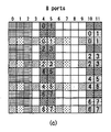
図8は、本発明が適用されることができる無線通信システムにおいて参照信号がマッピングされる資源を例示する図である。特に、図8は、normal CPが適用されたサブフレーム内でCSI-RSアンテナポートが1,2、4または8個である場合に対するCSI-RSパターンを例示する。 FIG. 8 is a diagram illustrating resources to which a reference signal is mapped in a wireless communication system to which the present invention can be applied. In particular, FIG. 8 illustrates a CSI-RS pattern for a case where there are 1, 4 or 8 CSI-RS antenna ports in a subframe to which normal CP is applied.
図8(a)は、1個または2個のCSI-RSアンテナポートによるCSI-RS送信に使用可能な20通りのCSI-RS構成を示したことであり、図8(b)は、4個のCSI-RSアンテナポートにより使用可能な10通りのCSI-RS構成を示したことであり、図8(c)は、8個のCSI-RSアンテナポートによりCSI-RS送信に使用可能な5通りの CSI-RS構成を示したことである。 FIG. 8 (a) shows 20 CSI-RS configurations that can be used for CSI-RS transmission with one or two CSI-RS antenna ports, and FIG. 8 (b) shows four. The 10 CSI-RS configurations that can be used by the CSI-RS antenna ports of the above are shown, and FIG. 8 (c) shows the 5 ways that can be used for CSI-RS transmission by the 8 CSI-RS antenna ports. The CSI-RS configuration of is shown.
このように、各CSI-RS構成によってCSI-RSが送信される無線資源(すなわち、RE対)が決定される。 In this way, each CSI-RS configuration determines the radio resource (ie, RE pair) to which the CSI-RS is transmitted.
特定セルに対してCSI-RS送信のために、1個あるいは2個のアンテナポートが設定されると、図8(a)に示す20通りのCSI-RS構成のうち設定されたCSI-RS構成による無線資源上においてCSI-RSが送信される。 When one or two antenna ports are set for CSI-RS transmission to a specific cell, the set CSI-RS configuration out of the 20 CSI-RS configurations shown in FIG. 8A. CSI-RS is transmitted on the radio resource by.
同様に、特定セルに対してCSI-RS送信のために4個のアンテナポートが設定されると、図8(b)に示す10通りのCSI-RS構成のうち設定されたCSI-RS構成による無線資源上においてCSI-RSが送信される。また、特定セルに対してCSI-RS送信のために、8個のアンテナポートが設定されると、図8(c)に示す5通りのCSI-RS構成のうち設定されたCSI-RS構成による無線資源上においてCSI-RSが送信される。 Similarly, when four antenna ports are set for CSI-RS transmission for a specific cell, the set CSI-RS configuration is used among the 10 CSI-RS configurations shown in FIG. 8 (b). CSI-RS is transmitted on the radio resource. Further, when eight antenna ports are set for CSI-RS transmission to a specific cell, the set CSI-RS configuration is used among the five CSI-RS configurations shown in FIG. 8 (c). CSI-RS is transmitted on the radio resource.
2個のアンテナポート別(すなわち、{15,16}、{17,18}、{19,20}、{21,22})に各々のアンテナポートに対するCSI-RSは、同じ無線資源にCDM(Code Division Multiplexing)されて送信される。アンテナポート15及び16を例とすると、アンテナポート15及び16に対する各々のCSI-RS複素シンボルは同一であるが、互いに異なる直交コード(例えば、ウォルシュコード(walsh code)が掛けられて、同じ無線資源にマッピングされる。アンテナポート15に対するCSI-RSの複素シンボルには、[1,1]が掛けられ、アンテナポート16に対するCSI-RSの複素シンボルには、[1-1]が掛けられて同じ無線資源にマッピングされる。これは、アンテナポート{17,18}、{19,20}、{21,22}も同様である。
For each of the two antenna ports (ie, {15, 16}, {17, 18}, {19, 20}, {21, 22}), the CSI-RS for each antenna port is CDM (ie) on the same radio resource. Code Division Multiplexing) and transmitted. Taking
UEは、送信されたシンボルに掛けられたコードを掛けて特定アンテナポートに対するCSI-RSを検出できる。すなわち、アンテナポート15に対するCSI-RSを検出するために掛けられたコード[11]を掛け、アンテナポート16に対するCSI-RSを検出するために掛けられたコード[1-1]を掛ける。
The UE can detect the CSI-RS for a specific antenna port by multiplying the transmitted symbol by the code. That is, the code [11] applied to detect the CSI-RS for the
図8(a)ないし(c)を参照すると、同じCSI-RS構成インデックスに該当するようになると、アンテナポート数が多いCSI-RS構成による無線資源は、CSI-RSアンテナポート数が少ないCSI-RS構成による無線資源を含む。例えば、CSI-RS構成0の場合、8個アンテナポート数に対する無線資源は、4個アンテナポート数に対する無線資源と1または2個のアンテナポート数に対する無線資源を全部含む。
With reference to FIGS. 8 (a) to 8 (c), when the same CSI-RS configuration index is applied, the radio resource with the CSI-RS configuration having a large number of antenna ports is the CSI-RS with a small number of antenna ports. Includes radio resources with RS configuration. For example, in the case of CSI-
図9は、本発明が適用されることができる無線通信システムにおいて参照信号がマッピングされる資源を例示する図である。 FIG. 9 is a diagram illustrating resources to which a reference signal is mapped in a wireless communication system to which the present invention can be applied.
特に、図9は、extended CPが適用されたサブフレーム内でCSI-RSアンテナポートが1,2、4または8個である場合に対するCSI-RSパターンを示す。 In particular, FIG. 9 shows a CSI-RS pattern for cases where there are 1, 4 or 8 CSI-RS antenna ports in a subframe to which extended CP is applied.
図9(a)は、1個または2個のCSI-RSアンテナポートによるCSI-RS送信に使用可能な16通りのCSI-RS構成を示したことであり、図8(b)は、4個のCSI-RSアンテナポートにより使用可能な8通りのCSI-RS構成を示したことであり、図8(c)は、8個のCSI-RSアンテナポートによりCSI-RS送信に使用可能な4通りのCSI-RS構成を示したことである。 FIG. 9A shows 16 CSI-RS configurations that can be used for CSI-RS transmission with one or two CSI-RS antenna ports, and FIG. 8B shows four. The eight CSI-RS configurations that can be used by the CSI-RS antenna ports of the above are shown, and FIG. 8 (c) shows the four types that can be used for CSI-RS transmission by the eight CSI-RS antenna ports. The CSI-RS configuration of is shown.
このように、各CSI-RS構成によってCSI-RSが送信される無線資源(すなわち、RE対)が決定される。 In this way, each CSI-RS configuration determines the radio resource (ie, RE pair) to which the CSI-RS is transmitted.
特定セルに対してCSI-RS送信のために、1個あるいは2個のアンテナポートが設定されると、図9(a)に示す16通りのCSI-RS構成のうち設定されたCSI-RS構成による無線資源上においてCSI-RSが送信される。 When one or two antenna ports are set for CSI-RS transmission to a specific cell, the set CSI-RS configuration out of the 16 CSI-RS configurations shown in FIG. 9A. CSI-RS is transmitted on the radio resource by.
同様に、特定セルに対してCSI-RS送信のために4個のアンテナポートが設定されると、図9(b)に示す8通りのCSI-RS構成のうち設定されたCSI-RS構成による無線資源上においてCSI-RSが送信される。また、特定セルに対してCSI-RS送信のために8個のアンテナポートが設定されると、図9(c)に示す4通りのCSI-RS構成のうち設定されたCSI-RS構成による無線資源上においてCSI-RSが送信される。一つのセルで複数のCSI-RS構成が使用されることができる。ノン-ゼロ電力(NZP:non-zero power)CSI-RSは、0個または1個のCSI-RS構成のみが利用され、ゼロ電力(ZP:zero power)CSI-RSは、0個または複数のCSI-RS構成が利用されることができる。 Similarly, when four antenna ports are set for CSI-RS transmission for a specific cell, the set CSI-RS configuration is used among the eight CSI-RS configurations shown in FIG. 9 (b). CSI-RS is transmitted on the radio resource. Further, when eight antenna ports are set for CSI-RS transmission for a specific cell, the radio according to the set CSI-RS configuration among the four CSI-RS configurations shown in FIG. 9 (c). CSI-RS is transmitted on the resource. Multiple CSI-RS configurations can be used in one cell. For non-zero power (NZP: non-zero power) CSI-RS, only 0 or 1 CSI-RS configuration is used, and for zero power (ZP: zero power) CSI-RS, 0 or more A CSI-RS configuration can be used.
上位階層により設定される16ビットのビットマップであるZP CSI-RS(ZeropowerCSI-RS)において1に設定された各ビット別に、UEは、上の表3及び表4の4個のCSI-RS列(column)に該当するREにおいて(上位階層により設定されたNZP CSI-RSを仮定するREと重複する場合を除外)ゼロ送信電力を仮定する。最上位ビット(MSB:Most Significant Bit)は、最も低いCSI-RS構成インデックスに該当し、ビットマップ内でその次のビットは、順に次のCSI-RS構成インデックスに該当する。 For each bit set to 1 in ZP CSI-RS (Zeropower CSI-RS), which is a 16-bit bitmap set by the upper layer, the UE is the four CSI-RS columns in Tables 3 and 4 above. In the RE corresponding to (collect), zero transmission power is assumed (except when it overlaps with the RE assuming NZP CSI-RS set by the upper layer). The most significant bit (MSB: Most Significant Bit) corresponds to the lowest CSI-RS configuration index, and the next bit in the bitmap corresponds to the next CSI-RS configuration index in order.
CSI-RSは、上の表3及び表4において(n_s mod 2)の条件を満たすダウンリンクスロット及びCSI-RSサブフレーム構成を満たすサブフレームにおいてのみで送信される。 CSI-RS is transmitted only in downlink slots satisfying the conditions of (n_s mod 2) in Tables 3 and 4 above and subframes satisfying the CSI-RS subframe configuration.
フレーム構造タイプ2(TDD)の場合、スペシャルサブフレーム、同期信号(SS)、PBCHまたはSIB 1(Systeminformationblocktype1)メッセージ送信と衝突されるサブフレームまたはページングメッセージ送信のために設定されたサブフレームにおいてCSI-RSは送信されない。 For frame structure type 2 (TDD), CSI-in a subframe that conflicts with a special subframe, sync signal (SS), PBCH or SIB 1 (Systemmation blocktype 1) message transmission or a subframe configured for paging message transmission. RS is not transmitted.
また、アンテナポートセットS(S={15}、S={15,16}、S={17,18}、S={19,20}またはS={21,22})内に属するあるアンテナポートに対するCSI-RSが送信されるREは、PDSCHまたは他のアンテナポートのCSI-RS送信に使用されない。 Also, an antenna belonging to the antenna port set S (S = {15}, S = {15,16}, S = {17,18}, S = {19,20} or S = {21,22}). REs to which CSI-RS is transmitted for the port are not used for CSI-RS transmission for PDSCH or other antenna ports.
CSI-RS送信に使用される時間-周波数資源は、データ送信に使用されることができないので、CSI-RSオーバーヘッドが増加するほど、データ処理量(スループット)が減少するようになる。これを考慮して、CSI-RSは、毎サブフレームごとに送信されるように構成されず、多数のサブフレームに該当する所定の送信周期ごとに送信されるように構成される。この場合、毎サブフレームごとにCSI-RSが送信される場合に比べて、CSI-RS送信オーバーヘッドが多く低くなることができる。 Since the time-frequency resources used for CSI-RS transmission cannot be used for data transmission, the amount of data processing (throughput) decreases as the CSI-RS overhead increases. In consideration of this, the CSI-RS is not configured to be transmitted every subframe, but is configured to be transmitted every predetermined transmission cycle corresponding to a large number of subframes. In this case, the CSI-RS transmission overhead can be much lower than in the case where the CSI-RS is transmitted every subframe.
CSI-RS送信のためのサブフレーム周期(以下、「CSI送信周期」と呼ぶ)(T_CSI-RS)及びサブフレームオフセット(Δ_CSI-RS)は、以下の表5のとおりである。 The subframe period (hereinafter referred to as "CSI transmission cycle") (T_CSI-RS) and subframe offset (Δ_CSI-RS) for CSI-RS transmission are shown in Table 5 below.
表5は、CSI-RSサブフレームの構成を例示する。 Table 5 illustrates the configuration of the CSI-RS subframe.
表5
表5を参照すると、CSI-RSサブフレーム構成(I_CSI-RS)によってCSI-RS送信周期(T_CSI-RS)及びサブフレームオフセット(Δ_CSI-RS)が決定される。 With reference to Table 5, the CSI-RS subframe configuration (I_CSI-RS) determines the CSI-RS transmission cycle (T_CSI-RS) and subframe offset (Δ_CSI-RS).
表5のCSI-RSサブフレーム構成は、先の 「SubframeConfig」フィールド及び「zeroTxPowerSubframeConfig」フィールドのうちのいいずれか一つに設定されることができる。CSI-RSサブフレーム構成は、NZP CSI-RS及びZP CSI-RSに対して個別的に(separately)設定されることができる。 The CSI-RS subframe configuration in Table 5 can be set in any one of the "SubframeConfig" and "zeroTxPowerSubframeConfig" fields above. The CSI-RS subframe configuration can be set separately for the NZP CSI-RS and ZP CSI-RS.
CSI-RSを含むサブフレームは、以下の数式13を満たす。
The subframe containing CSI-RS satisfies the following
![]()
![]()
数式13中、T_CSI-RSは、CSI-RS送信周期、Δ_CSI-RSは、サブフレームオフセット値、n_fは、システムフレームナンバー、n_sは、スロットナンバーを意味する。
In
サービングセルに対して送信モード9(transmission mode 9)が設定されたUEの場合、UEは、一つのCSI-RS資源構成が設定されることができる。サービングセルに対して送信モード10(transmission mode 10)が設定されたUEの場合、UEは、一つまたはそれ以上のCSI-RS資源構成(ら)が設定されることができる。 In the case of a UE in which the transmission mode 9 (transmission mode 9) is set for the serving cell, the UE can be set with one CSI-RS resource configuration. In the case of a UE in which the transmission mode 10 (transmission mode 10) is set for the serving cell, the UE can be set with one or more CSI-RS resource configurations (etc.).
CSI-RS構成(configuration)CSI-RS configuration (configuration)
現在、LTE標準においてCSI-RS構成(configuration)に関するパラメータにantenna portsCount、subframeConfig、resourceConfigなどが存在する。このようなパラメータは、CSI-RSがいくつのアンテナポートから送信されているか、CSI-RSが送信されるサブフレームの周期及びオフセットがどうなっているか、そして該当サブフレームでどんなRE位置(例えば、周波数とOFDMシンボルインデックス)から送信されているかなどを指示する。具体的に、基地局は、特定CSI-RS構成をUEに指示/伝達する時、次のような内容のパラメータ/情報を伝達する。 Currently, there are antenna portsCount, subframeConfig, resourceConfig, etc. as parameters related to CSI-RS configuration in the LTE standard. Such parameters include how many antenna ports the CSI-RS is transmitted from, what is the period and offset of the subframe in which the CSI-RS is transmitted, and what RE position (eg, for example) is in that subframe. It indicates whether it is transmitted from the frequency and OFDM symbol index). Specifically, when the base station instructs / transmits the specific CSI-RS configuration to the UE, the base station transmits parameters / information having the following contents.
-antenna portsCount:CSI-RSの送信のために使用されるアンテナポート数を表すパラメータ(Parameter represents the number of antenna ports used for transmission of CSI reference signals)(例えば、1 CSI-RSポート、2 CSI-RSポート、4 CSI-RSポート、あるいは8 CSI-RSポート) -antenna portsCount: A parameter that represents the number of antenna ports used to transmit CSI-RS (Parameter presents the number of antenna ports used for for transmission of CSI defense CSI ports, for example, 1 RS Ports) Port, 4 CSI-RS port, or 8 CSI-RS port)
-resourceConfig:CSI-RS割り当て資源位置に関するパラメータ -resourceConfig: Parameter related to CSI-RS allocated resource location
-subframeConfig:CSI-RSが送信されるサブフレーム周期及びオフセットに関するパラメータ -subframeConfig: Parameters related to the subframe period and offset at which CSI-RS is transmitted
-p-C:CSIフィードバックCSI-RSのための参照PDSCH送信パワーに関するUEの仮定に関して、Pcは、UEがCSIフィードバックを導き出す時にCSI-RS EPREに対してPDSCH EPREの仮定された割合に該当し、1dB大きさの単位として[-8,15]dB範囲の値を取る(Regarding UE assumption on reference PDSCH transmitted power for CSI feedback CSI-RS, Pc is the assumed ratio of PDSCH EPRE to CSI-RS EPRE when UE derives CSI feedback and takes values in the range of [-8, 15] dB with 1 dB step size) -p-C: CSI Feedback With respect to the UE's assumptions regarding the reference PDSCH transmit power for CSI-RS, Pc corresponds to the assumed ratio of PDSCH EPRE to CSI-RS EPRE when the UE derives CSI feedback. The value in the [-8,15] dB range is taken as the unit of the 1 dB size (Regarding UE assertion on feedback PDSCH transmitted power for CSI fedback CSI-RS, Pc is the assumed ray derives CSI fedback and takes values in the range of [-8, 15] dB with 1 dB step size)
-zeroTxPowerResourceConfigList:zero-powerCSI-RS構成に関するパラメータ -zeroTxPowerResourceConfigList: parameters related to zero-powerCSI-RS configuration
-zeroTxPowerSubframeConfig:zero-power CSI-RSが送信されるサブフレーム周期及びオフセットに関するパラメータ -zeroTxPowerSubframeConfig: Parameters related to the subframe period and offset at which the zero-power CSI-RS is transmitted.
マッシブMIMO(Massive MIMO)Massive MIMO (Massive MIMO)
多数のアンテナを有するMIMOシステムをマッシブMIMO(Massive MIMO)システムと呼ぶことができ、スペクトル効率(spectral efficiency)、エネルギー効率(energy efficiency)、プロセシング複雑度(processing complexity)を向上させるための手段として注目されつつある。 A MIMO system having a large number of antennas can be called a Massive MIMO system, and is attracting attention as a means for improving spectral efficiency, energy efficiency, and processing complexity. Is being done.
最近、3GPPでは、未来の移動通信システムのスペクトル効率性に対する要求事項を満足させるために、マッシブMIMOシステムに対する議論が始まった。マッシブMIMOは、全-次元MIMO(FD-MIMO:Full-Dimension MIMO)とも呼ばれる。 Recently, at 3GPP, discussions on massive MIMO systems have begun to meet the requirements for spectral efficiency of future mobile communication systems. Massive MIMO is also referred to as Full-Dimension MIMO (FD-MIMO: Full-Dimension MIMO).
LTEリリース(Rel:release)-12以後の無線通信システムでは、能動アンテナシステム(AAS:Active Antenna System)の導入が考慮されている。 In the wireless communication system after LTE release (Rel: release) -12, the introduction of an active antenna system (AAS: Active Antenna System) is considered.
信号の位相及び大きさを調整することができる増幅器とアンテナが分離されている従来の 受動アンテナシステムとは異なり、AASは、各々のアンテナが増幅器のような能動素子を含むように構成されたシステムを意味する。 Unlike traditional passive antenna systems, where the amplifier and antenna are separated so that the phase and magnitude of the signal can be adjusted, AAS is a system in which each antenna is configured to include an active element such as an amplifier. Means.
AASは、能動アンテナの使用によって増幅器とアンテナとを接続するための別のケーブル、コネクター、その他ハードウェアなどを必要とせず、したがってエネルギー及び運用費の側面で効率性が高い特徴を有する。特に、AASは、各アンテナ別電子式ビーム制御(electronic beam control)方式を支援するから、ビーム方向及びビーム幅を考慮した精巧なビームパターン形成または3次元ビームパターンを形成する等の進歩したMIMO技術を可能にする。 The AAS does not require additional cables, connectors, or other hardware to connect the amplifier to the antenna by using an active antenna, and thus has a highly efficient feature in terms of energy and operating costs. In particular, since AAS supports an electronic beam control method for each antenna, advanced MIMO technology such as elaborate beam pattern formation or three-dimensional beam pattern formation in consideration of beam direction and beam width is performed. To enable.
AASの進歩したアンテナシステムの導入に伴い、多数の入出力アンテナと多次元アンテナ構造を有する大規模MIMO構造もまた考慮されている。一例として、従来の一字型アンテナ配列とは異なり、2次元(2D:2-Dimension)アンテナ配列を形成する場合、AASの能動アンテナにより3次元ビームパターンを形成できる。 With the introduction of advanced antenna systems in AAS, large-scale MIMO structures with multiple input / output antennas and multidimensional antenna structures are also being considered. As an example, unlike the conventional single-character antenna array, when forming a two-dimensional (2D: 2-Dimension) antenna array, a three-dimensional beam pattern can be formed by the active antenna of AAS.
図10は、本発明が適用されることができる無線通信システムにおいて、64個のアンテナ要素(antenna elements)を有する2次元能動アンテナシステムを例示する。 FIG. 10 illustrates a two-dimensional active antenna system having 64 antenna elements in a wireless communication system to which the present invention can be applied.
図10では、一般的な2次元(2D:2Dimension)アンテナ配列を例示しており、図10のようにN_t=N_v・N_h個のアンテナが正方形の模様を有する場合を考慮することができる。ここで、N_hは、水平方向にアンテナ列の個数を、N_vは、垂直方向にアンテナ行の個数を示す。 FIG. 10 illustrates a general two-dimensional (2D: 2Dimension) antenna arrangement, and it is possible to consider the case where N_t = N_v · N_h antennas have a square pattern as shown in FIG. Here, N_h indicates the number of antenna columns in the horizontal direction, and N_v indicates the number of antenna rows in the vertical direction.
このような2D構造のアンテナ配列を利用すると、3次元空間で送信ビームを制御できるように無線波長(radio wave)が垂直方向(高度(elevation))及び水平方向(方位角(azimuth))に全部制御できる。このようなタイプの波長制御メカニズムを3次元ビームフォーミングと呼ぶことができる。 When the antenna arrangement of such a 2D structure is used, the radio wavelength (radio wave) is all in the vertical direction (elevation) and the horizontal direction (azimuth) so that the transmitted beam can be controlled in the three-dimensional space. Can be controlled. This type of wavelength control mechanism can be called three-dimensional beamforming.
図11は、本発明が適用されることができる無線通信システムにおいて基地局または端末がAAS基盤の3D(3-Dimension)ビームフォーミングが可能な多数の送/受信アンテナを有しているシステムを例示する。 FIG. 11 illustrates a system in which a base station or terminal has a large number of transmit / receive antennas capable of AAS-based 3D (3-Dimation) beamforming in a wireless communication system to which the present invention can be applied. To do.
図11は、上述の例を図式化したことで、2次元アンテナ配列(すなわち、2D-AAS)を利用した3D MIMOシステムを例示する。 FIG. 11 illustrates a 3D MIMO system using a two-dimensional antenna array (ie, 2D-AAS) by schematizing the above example.
送信アンテナの観点で前記3次元ビームパターンを活用する場合、ビームの水平方向だけでなく垂直方向への準-静的または動的なビームフォーミングを行うことができ、一例として垂直方向のセクター形成などの応用を考慮できる。 When utilizing the three-dimensional beam pattern from the viewpoint of a transmitting antenna, quasi-static or dynamic beamforming can be performed not only in the horizontal direction of the beam but also in the vertical direction, for example, vertical sector formation and the like. Can be considered for application.
また、受信アンテナ観点では、大規模受信アンテナを活用して受信ビームを形成する時、アンテナ配列利得(antenna array gain)に応じる信号電力上昇効果を期待することができる。したがって、アップリンクの場合、基地局が多数のアンテナを介して端末から送信される信号を受信することができ、このとき、端末は、干渉影響を減らすために大規模受信アンテナの利得を考慮して、自身の送信電力を非常に低く設定できるという長所がある。 Further, from the viewpoint of the receiving antenna, when the receiving beam is formed by utilizing the large-scale receiving antenna, the effect of increasing the signal power according to the antenna array gain (antenna array gain) can be expected. Therefore, in the case of uplinks, the base station can receive signals transmitted from the terminal through multiple antennas, where the terminal considers the gain of the large receiving antenna to reduce the effects of interference. It has the advantage that it can set its own transmission power very low.
図12は、本発明が適用されることができる無線通信システムにおいて交差偏波(cross polarization)を有する2次元アンテナシステムを例示する。 FIG. 12 illustrates a two-dimensional antenna system having cross polarization in a wireless communication system to which the present invention can be applied.
偏波(Polarization)を考慮した2D平面配列アンテナ(planar antenna array)モデルの場合、図11のように図式化できる。 In the case of a 2D planar antenna array model in consideration of polarization, it can be schematized as shown in FIG.
受動的アンテナ(passive antenna)に応じる既存のMIMOシステムとは異なり、能動アンテナに基盤したシステムは、各アンテナ要素(element)に付着された(または含まれた)能動素子(例えば、増幅器)に加重値を適用することによって、アンテナ要素の利得(gain)を動的に調節できる。放射パターン(radiation pattern)は、アンテナ要素の個数、アンテナ間隔(spacing)などのような アンテナ配置(arrangement)に依存するので、アンテナシステムは、アンテナ要素レベルでモデリングされることができる。 Unlike existing MIMO systems that respond to a passive antenna, a system based on an active antenna is weighted on an active element (eg, an amplifier) attached (or included) to each antenna element. By applying the value, the gain of the antenna element can be dynamically adjusted. Since the radiation pattern depends on the number of antenna elements, antenna arrangement such as antenna spacing, etc., the antenna system can be modeled at the antenna element level.
図12の例示のようなアンテナ配列モデルを(M,N,P)で表すことができ、これは、アンテナ配列構造を特徴づけるパラメータに該当する。 The antenna array model as illustrated in FIG. 12 can be represented by (M, N, P), which corresponds to the parameters that characterize the antenna array structure.
Mは、各列(すなわち、垂直方向で)で同じ偏波(polarization)を有しているアンテナ要素(antenna element)の個数(すなわち、各列で+45゜の傾斜(slant)を有しているアンテナ要素の個数または各列で-45゜の傾斜(slant)を有しているアンテナ要素の個数)を表す。 M has a number of antenna elements (ie, + 45 ° slant) in each row (ie, in the vertical direction) having the same polarization. Represents the number of antenna elements or the number of antenna elements having a -45 ° slope in each row).
Nは、水平方向の列の個数(すなわち、水平方向でアンテナ要素の個数)を表す。 N represents the number of rows in the horizontal direction (ie, the number of antenna elements in the horizontal direction).
Pは、偏波(polarization)の次元(dimension)の個数を表す。図11の場合のように、交差偏波(cross polarization)の場合、P=2であるが、同一偏波(co-polarization)の場合、P=1である。 P represents the number of dimensions of polarization. As in the case of FIG. 11, in the case of cross polarization, P = 2, but in the case of co-polarization, P = 1.
アンテナポート(antenna port)は、物理的アンテナ要素(physical antenna element)にマッピングされることができる。アンテナポート(antenna port)は、該当アンテナポートと関連した参照信号により定義されることができる。例えば、LTEシステムにおいてアンテナポート0は、CRS(Cell-specific Reference signal)と関連し、アンテナポート6は、PRS(Positioning Reference signal)と関連することができる。
The antenna port (antenna port) can be mapped to a physical antenna element (physical antenna element). An antenna port can be defined by a reference signal associated with that antenna port. For example, in the LTE system, the
一例として、アンテナポートと物理的アンテナ要素との間は、一対一にマッピングされることができる。単一の交差偏波(cross polarization)アンテナ要素がダウンリンクMIMOまたはダウンリンク送信ダイバーシチのために使用される場合などがこれに該当することができる。例えば、アンテナポート0は、一つの物理的アンテナ要素にマッピングされることに対し、アンテナポート1は、他の物理的アンテナ要素にマッピングされることができる。この場合、端末の立場では、2個のダウンリンク送信が存在する。一つは、アンテナポート0のための参照信号と関連し、残りの一つは、アンテナポート1のための参照信号と関連する。
As an example, there can be a one-to-one mapping between the antenna port and the physical antenna element. This can be the case, for example, when a single cross polarization antenna element is used for downlink MIMO or downlink transmit diversity. For example,
他の一例として、単一のアンテナポートは、多重の物理的アンテナ要素にマッピングされることができる。ビームフォーミング(beamforming)のために使用される場合などがこれに該当することができる。ビームフォーミングは、多重の物理的アンテナ要素を利用することによって、ダウンリンク送信が特定端末に向かうようにすることができる。一般に多重の交差偏波(cross polarization)アンテナ要素の多重の列(column)から構成されるアンテナ配列(antenna array)を使用してこれを達成できる。この場合、端末の立場では、単一のアンテナポートから発生した単一のダウンリンク送信が存在する。一つは、アンテナポート0のためのCRSと関連し、残りの一つは、アンテナポート1のためのCRSと関連する。
As another example, a single antenna port can be mapped to multiple physical antenna elements. This can be the case, for example, when it is used for beamforming. Beamforming can be directed to a particular terminal by utilizing multiple physical antenna elements. This can generally be achieved using an antenna array consisting of multiple columns of multiple cross polarization antenna elements. In this case, from the terminal standpoint, there is a single downlink transmission originating from a single antenna port. One is associated with the CRS for
すなわち、アンテナポートは、基地局で物理的アンテナ要素から送信された実際ダウンリンク送信でない端末立場でのダウンリンク送信を示す。 That is, the antenna port indicates downlink transmission from the terminal standpoint that is not the actual downlink transmission transmitted from the physical antenna element at the base station.
他の一例として、多数のアンテナポートがダウンリンク送信のために使用されるが、各アンテナポートは、多重の物理的アンテナ要素にマッピングされることができる。この場合は、アンテナ配列がダウンリンクMIMOまたはダウンリンクダイバーシチのために使用される場合などがこれに該当することができる。例えば、アンテナポート0及び1は、それぞれ多重の物理的アンテナ要素にマッピングされることができる。この場合、端末の立場では、2個のダウンリンク送信が存在する。一つは、アンテナポート0のための参照信号と関連し、残りの一つは、アンテナポート1のための参照信号と関連する。
As another example, a large number of antenna ports are used for downlink transmission, but each antenna port can be mapped to multiple physical antenna elements. In this case, this can be the case, for example, when the antenna array is used for downlink MIMO or downlink diversity. For example,
FD-MIMOでは、データストリームのMIMOプリコーディングは、アンテナポート仮像化、トランシーバーユニット(または送受信ユニット)(TXRU:transceiver unit)仮像化、アンテナ要素パターンを経ることができる。 In FD-MIMO, MIMO precoding of a data stream can go through antenna port pseudo-images, transceiver unit (or transceiver unit) (TXRU: transceiver unit) pseudo-images, and antenna element patterns.
アンテナポート仮像化は、アンテナポート上のストリームがTXRU上においてプリコーディングされる。TXRU仮像化は、TXRU信号がアンテナ要素上においてプリコーディングされる。アンテナ要素パターンは、アンテナ要素から放射される信号は、方向性の利得パターン(directional gain pattern)を有することができる。 Antenna port pseudomorphization is where the stream on the antenna port is precoded on the TXRU. In TXRU pseudomorphization, the TXRU signal is precoded on the antenna element. As for the antenna element pattern, the signal radiated from the antenna element can have a directional gain pattern (directal gain pattern).
従来の送受信機(transceiver)モデリングでは、アンテナポートとTXRUとの間の静的な一対一マッピングが仮定され、TXRU仮像化効果は、TXRU仮像化及びアンテナ要素パターンの効果ともを含む静的な(TXRU)アンテナパターンに合わせられる。 Traditional transceiver modeling assumes static one-to-one mapping between the antenna port and the TXRU, and the TXRU pseudomorphization effect is static, including the effects of TXRU pseudomorphization and antenna element patterns. (TXRU) Matched to the antenna pattern.
アンテナポート仮像化は、周波数-選択的な方法で行われることができる。LTEでアンテナポートは、参照信号(またはパイロット)と共に定義される。例えば、アンテナポート上においてプリコーディングされたデータ送信のために、DMRSがデータ信号と同じ帯域幅で送信され、DMRSとデータともが同じプリーコーダー(または同じTXRU仮像化プリコーディング)でプリコーディングされる。CSI測定のために、CSI-RSは、多重のアンテナポートを介して送信される。CSI-RS送信において、端末においてデータプリコーディングベクトルのためのTXRU仮像化プリコーディング行列を推定できるようにCSI-RSポートとTXRUとの間のマッピングを特徴づけるプリーコーダーは、固有な行列で設計されることができる。 Antenna port pseudomorphization can be done in a frequency-selective way. In LTE, an antenna port is defined with a reference signal (or pilot). For example, for precoding data transmission on an antenna port, DMRS is transmitted with the same bandwidth as the data signal, and DMRS and data are precoded with the same precoder (or the same TXRU pseudo-imaging precoding). To. For CSI measurements, the CSI-RS is transmitted through multiple antenna ports. In CSI-RS transmission, the precoder that characterizes the mapping between the CSI-RS port and TXRU is designed with a unique matrix so that the terminal can estimate the TXRU pseudo-imaged precoding matrix for the data precoding vector. Can be done.
TXRU仮像化方法は、1次元TXRU仮像化(1D TXRU virtualization)と2次元TXRU仮像化(2D TXRU virtualization)が論議され、これについて以下の図面を参照して説明する。 As for the TXRU virtualization method, one-dimensional TXRU virtualization and two-dimensional TXRU virtualization have been discussed, and this will be described with reference to the following drawings.
図13は、本発明が適用されることができる無線通信システムにおいてトランシーバーユニットモデルを例示する。 FIG. 13 illustrates a transceiver unit model in a wireless communication system to which the present invention can be applied.
1D TXRU仮像化において、M_TXRU個のTXRUは、同じ偏波(polarization)を有する単一の列(column)アンテナ配列で構成されるM個のアンテナ要素と関連する。 In 1D TXRU pseudomorphization, M_TXRU TXRUs are associated with M antenna elements composed of a single column antenna array with the same polarization.
2D TXRU仮像化において、先の図11のアンテナ配列モデル構成(M、N、P)に相応するTXRUモデル構成は、(M_TXRU、N、P)で表すことができる。ここで、M_TXRUは、2D同じ列、同じ偏波(polarization)に存在するTXRUの個数を意味し、M_TXRU≦Mを常に満たす。すなわち、TXRUの総個数は、M_TXRU×N×Pのようである。 In the 2D TXRU pseudomorphization, the TXRU model configuration corresponding to the antenna array model configuration (M, N, P) of FIG. 11 above can be represented by (M_TXRU, N, P). Here, M_TXRU means the number of TXRUs existing in the same 2D sequence and the same polarization, and always satisfies M_TXRU ≦ M. That is, the total number of TXRUs seems to be M_TXRU × N × P.
TXRU仮像化モデルは、アンテナ要素とTXRUとの相関関係に応じて、図12(a)のようにTXRU仮像化(virtualization)モデルオプション-1:サブ-配列分割モデル(sub-array partition model)と図12(b)のようにTXRU仮像化モデルオプション-2:全域接続(full-connection)モデルに区分されることができる。 The TXRU virtualization model is a TXRU virtualization model option-1: a sub-array partition model, as shown in FIG. 12A, depending on the correlation between the antenna element and the TXRU. ) And TXRU virtualization model option-2: full-connection model can be classified as shown in FIG. 12 (b).
図13(a)を参照すると、サブ-配列分割モデル(sub-array partition model)の場合、アンテナ要素は、多重のアンテナ要素グループに分割され、各TXRUは、グループのうちのいずれか一つと接続される。 With reference to FIG. 13 (a), in the case of the sub-array partition model, the antenna elements are divided into multiple antenna element groups, and each TXRU is connected to any one of the groups. Will be done.
図13(b)を参照すると、全域接続(full-connection)モデルの場合、多重のTXRUの信号が結合されて、単一のアンテナ要素(またはアンテナ要素の配列)に伝達される。 Referring to FIG. 13 (b), in the case of a full-connection model, multiple TXRU signals are combined and transmitted to a single antenna element (or array of antenna elements).
図13中、qは、一つの列(column)内のM個の同じ偏波(co-polarized)を有するアンテナ要素の送信信号ベクトルである。wは、広帯域TXRU仮像化加重値ベクトル(wideband TXRU virtualization weight vector)であり、Wは、広帯域TXRU仮像化加重値行列(wideband TXRU virtualization Weight Matrix)である。xは、M_TXRU個のTXRUの信号ベクトルである。 In FIG. 13, q is a transmission signal vector of M antenna elements having the same co-polarized in one column. w is a wideband TXRU virtualization weight vector (wideband TXRU virtualization weight vector), and W is a wideband TXRU virtualization weight matrix (wideband TXRU virtualization Weight). x is a signal vector of M_TXRU TXRUs.
ここで、アンテナポートとTXRUとのマッピングは、一対一(1-to-1)または一対多(1-to-many)でありうる。 Here, the mapping between the antenna port and the TXRU can be one-to-one (1-to-1) or one-to-many (1-to-many).
図13においてTXRUとアンテナ要素との間のマッピング(TXRU-to-element mapping)は、一つの例示を示すことに過ぎず、本発明がこれに限定されるものではなく、ハードウェアの観点でその他多様な形態により具現化されることができるTXRUとアンテナ要素との間のマッピングにも本発明が同様に適用されることができる。 In FIG. 13, the mapping between the TXRU and the antenna element (TXRU-to-element mapping) is merely an example, and the present invention is not limited thereto. The present invention can be similarly applied to the mapping between the TXRU and the antenna element, which can be embodied in various forms.
CSI(Channel-State Information)-Reference signal(CSI-RS)定義CSI (Channel-State Information) -Reference signal (CSI-RS) definition
送信モード9が設定されたサービングセル及びUEに対して、UEは、一つのCSI-RS資源構成を設定されることができる。送信モード10が設定されたサービングセル及びUEに対して、UEは、一つ以上のCSI-RS資源構成(ら)を設定されることができる。CSI-RSに対してnon-zero送信電力を仮定しなければならないUEのための以下のパラメータは、各々のCSI-RS資源構成に対する上位階層シグナリングを介して設定される:
The UE can set one CSI-RS resource configuration for the serving cell and the UE for which the
-CSI-RS資源構成識別子(UEに送信モード10が設定された場合)
-CSI-RS resource configuration identifier (when
-CSI-RSポートの数 -Number of CSI-RS ports
-CSI-RS構成 -CSI-RS configuration
-CSI-RSサブフレーム構成I_(CSI-RS) -CSI-RS subframe configuration I_ (CSI-RS)
-CSIフィードバック(P_c)のための基準PDSCH送信電力に対するUEの仮定(UEに送信モード9が設定された場合)
-UE assumptions for reference PDSCH transmit power for CSI feedback (P_c) (when transmit
-UEに送信モード10が設定されると、各々のCSIプロセスに対するCSIフィードバック(P_c)のための基準PDSCH送信電力に対するUE仮定。CSIサブフレームセットC_(CSI,0)及びC_(CSI,1)がCSIプロセスのための上位階層により設定されると、CSIプロセスの各CSIサブフレームセットのためのP_cが設定される。
-When transmit
-Pseudo-randomシーケンス生成器パラメータ(n_ID). -Pseudo-random sequence generator parameter (n_ID).
-UEが上位階層パラメータCSI-Reporting-Typeを設定され、CSI報告タイプがCSIプロセスに対する「CLASS A」に設定された場合、CDMタイプパラメータ。 -CDM type parameter if the UE is set to the upper hierarchy parameter CSI-Reporting-Type and the CSI reporting type is set to "CLASS A" for the CSI process.
-UEに送信モード10が設定された場合、以下のパラメータを有するCRSアンテナポート及びCSI-RSアンテナポートのQCL type BのUE仮定に対する上位階層パラメータqcl-CRS-Info-r11:
-When the
-qcl-ScramblingIdentity-r11. -qcl-ScramblingIdentity-r11.
-crs-PortsCount-r11. -crs-PortsCount-r11.
-mbsfn-SubframeConfigList-r11. -mbsfn-SubframeConfigList-r11.
P_cは、UEがCSIフィードバックを導き出し1dBステップの大きさで[-8,15]dB範囲内の値を取る時、CSI-RS EPRE(Energy Per Resource element)に対するPDSCH EPREの推定された割合であり、ここでPDSCH EPREは、セル関連RS EPREに対するPDSCH EPREの割合に対するシンボル数と対応する。 P_c is the estimated ratio of PDSCH EPRE to CSI-RS EPRE (Energy Per Resource element) when the UE derives CSI feedback and takes a value in the [-8,15] dB range with a magnitude of 1 dB step. Here, PDSCH EPRE corresponds to the number of symbols to the ratio of PDSCH EPRE to cell-related RS EPRE.
UEは、サービングセルの同じサブフレームにおいてCSI-RS及びPMCHの構成を期待しない。 The UE does not expect CSI-RS and PMCH configurations in the same subframe of the serving cell.
フレーム構造タイプ2サービングセルと4個のCRSポートの場合、UEは、一般CPの場合[20-31]セットまたは拡張CPの場合[16-27]セットに属したCSI-RS構成インデックスを受信することを期待しない。
For
UEは、CSI-RS資源構成のCSI-RSアンテナポートの間には、遅延拡散、ドップラー拡散、ドップラーシフト、平均利得及び平均遅延に対してQCLされると仮定することができる。 The UE can be assumed to be QCLed for delay spread, Doppler spread, Doppler shift, average gain and average delay between CSI-RS antenna ports in the CSI-RS resource configuration.
送信モード10及びQCL type Bが設定されたUEは、CSI-RS資源構成に対応するqcl-CRS-Info-r11と関連したアンテナポート0-3を仮定することができ、CSI-RS資源構成に対応するアンテナポート15-22は、ドップラーシフト(Doppler shift)及びドップラー拡散(Doppler spread)に対してQCLされたと仮定することができる。
The UE in which the
UEに送信モード10及び上位階層パラメータCSI-Reporting-Typeが設定され、CSI-Reporting-Typeは、「CLASS B」に設定され、CSIプロセスのために構成されたCSI-RS資源の個数が一つ以上で、QCL type Bが設定された場合、UEは、上位階層パラメータqcl-CRS-Info-r11と互いに異なる値を有するCSIプロセスに対するCSI-RS資源構成を受信することを期待しない。
The UE is set to the transmit
CSI-RS送信のために構成/設定されたサブフレームにおいて、参照信号シーケンス
![]()
x-valued)変調シンボル
![]()
![]()
x-valued) Modulation symbol
![]()
CDMTypeがCDM4に該当しない場合、以下の数式14によるマッピングが行われることができる。
When CDMType does not correspond to CDM4, mapping by the following
CDMTypeがCDM4に該当する場合、以下の数式15によるマッピングが行われることができる。
When CDMTtype corresponds to CDM4, mapping by the following
数式15の
![]()
![]()
![]()
![]()
表6
OFDMヌメロロジー(numerology)OFDM numerology
さらに多くの通信機器がより大きな通信容量を要求するようになるにつれて、従来のRAT(Radio Access Technology)に比べて向上したmobile broadband通信に対する必要性が台頭しつつある。また、多数の機器及び事物を接続していつ、どこででも多様なサービスを提供するmassive MTC(Machine Type Communications)もやはり、次世代通信において考慮される主な問題の一つである。 それだけでなく、次世代通信で信頼度(reliability)及び遅延(latency)に敏感なサービス/UEを考慮した通信システムデザインが論議されている。このように、enhanced mobile broadband communication、massive MTC、URLLC(Ultra-Reliable and Low Latency Communication)などを考慮した次世代RATの導入が論議されており、このような技術を「new RAT(NR)」と通称することができる。 As more and more communication devices demand larger communication capacities, the need for improved mobile broadband communication as compared with conventional RATs (Radio Access Technology) is emerging. In addition, massive MTC (Machine Type Communications), which connects a large number of devices and things to provide various services anytime and anywhere, is also one of the main problems to be considered in next-generation communication. Not only that, communication system designs that consider services / UEs that are sensitive to reliability and latency in next-generation communications are being discussed. In this way, the introduction of next-generation RATs that take into account enhanced mobile broadband communication, massive MTC, URLLC (Ultra-Reliable and Low Latency Communication), etc. has been discussed, and such technologies have been discussed as "new RAT" (NR). Can be commonly called.
New RATシステムは、OFDM送信方式またはこれと類似の送信方式を使用し、代表的に以下の表3のOFDMヌメロロジーを有する。 The New RAT system uses an OFDM transmission method or a transmission method similar thereto, and typically has the OFDM numerology shown in Table 3 below.
表3
Self-contained subframe structureSelf-contined subframe structure
TDDシステムにおいてデータ送信遅延を最小化するために、5世代New RATでは、図14のように、制御チャネルとデータチャネルがTDMされたself-contained subframe構造が考慮されている。 In order to minimize the data transmission delay in the TDD system, the 5th generation New LAT considers a self-contained subframe structure in which the control channel and the data channel are TDM, as shown in FIG.
図14は、本発明が適用されることができるself-contained subframe構造を例示する。 FIG. 14 illustrates a self-contined subframe structure to which the present invention can be applied.
図14において斜線領域は、DCI伝達のための物理チャネルPDCCHの送信領域を示し、黒色部分は、UCI(Uplink Control Information)伝達のための物理チャネルPUCCHの送信領域を示す。 In FIG. 14, the shaded area shows the transmission area of the physical channel PDCCH for DCI transmission, and the black part shows the transmission area of the physical channel PUCCH for UCI (Uplink Control Information) transmission.
DCIを介してeNBがUEに伝達する制御情報には、UEが知っていなければならないcell構成に関する情報、DLスケジューリングなどのDL特定(specific)情報、及び/またはUL承認(grant)などのようなUL特定情報などが存在できる。また、UCIを介してUEがeNBに伝達する制御情報には、DLデータに対するHARQのACK/NACK報告、DLチャネル状態に対するCSI報告、及び/またはSR(Scheduling Request)などが存在できる。 The control information that the eNB transmits to the UE via DCI includes information about the cell configuration that the UE must know, DL specific information such as DL scheduling, and / or UL approval (grant). UL specific information and the like can exist. Further, the control information transmitted by the UE to the eNB via the UCI may include HARQ ACK / NACK reports for DL data, CSI reports for DL channel states, and / or SR (Scheduling Request).
図14中、表示がない領域は、ダウンリンクデータのための物理チャネルPDSCH送信領域として使用されることもでき、アップリンクデータのための物理チャネルPUSCH送信領域として使用されることもできる。このような構造の特徴は、一つのSF(subframe)内でDL送信とUL送信が順次に行われて、該当SF内でDLデータを送信し、ULACK/NACKを受信することもできる。したがって、本構造をしたがう場合、データ送信エラー発生時にデータの再送信までかかる時間が減るようになり、これによって最終データ伝達の遅延(latency)が最小化されることができる。 In FIG. 14, the area not displayed can be used as a physical channel PDSCH transmission area for downlink data, or can be used as a physical channel PUSCH transmission area for uplink data. The feature of such a structure is that DL transmission and UL transmission are sequentially performed in one SF (subframe), DL data is transmitted in the corresponding SF, and ULACK / NACK can be received. Therefore, when this structure is followed, the time required for data re-transmission when a data transmission error occurs can be reduced, and thus the delay of final data transmission (latency) can be minimized.
このようなself-contained subframe構造で基地局とUEが送信モードから受信モードに転換される過程または受信モードから送信モードに転換される過程のための時間間隔(time gap)が必要である。このために、subframe構造でDLからULに転換される時点の一部OFDM symbolがGPとして設定されることができ、このようなsubframe typeは、「self-contained SF」と呼ぶことができる。 In such a self-contined subframe structure, a time interval (time gap) is required for the process of converting the base station and the UE from the transmission mode to the reception mode or the process of converting the reception mode to the transmission mode. For this reason, a partial OFDM symbol at the time of conversion from DL to UL in the subframe structure can be set as GP, and such a subframe type can be called "self-contined SF".
Analog beamformingAnalog beamforming
Millimeter Wave(mmW)では、波長が短くなって同一面積に多数のアンテナ要素の設置が可能になる。すなわち、30GHz帯域で波長は、1cmであって、5by5cmのパネルに0.5lambda(波長)間隔で2-次元配列形態で総64(8X8)個のアンテナ要素(element)設置が可能である。したがって、mmWでは、多数個のアンテナ要素を使用してbeamforming(BF)利得を高めてカバレッジを増加させるか、throughputを高めようとする。 In Millimeter Wave (mmW), the wavelength is shortened and a large number of antenna elements can be installed in the same area. That is, the wavelength is 1 cm in the 30 GHz band, and a total of 64 (8 x 8) antenna elements can be installed in a 2-dimensional array form at 0.5 lambda (wavelength) intervals on a panel of 5 by 5 cm. Therefore, in mmW, a large number of antenna elements are used to increase the beamforming (BF) gain to increase the coverage or to increase the throughput.
この場合に、アンテナ要素別に送信パワー及び位相調節が可能なようにTXRU(transceiver unit)を有すると、周波数資源別に独立的なbeamformingが可能である。しかしながら、100余個のアンテナ要素全部にTXRUを設置するには、価格側面で実效性が落ちるという問題を有するようになる。したがって、一つのTXRUに多数のアンテナ要素をマッピングし、analog phase shifterでビームの方向を調節する方式が考慮されている。このようなanalog beamforming方式は、全帯域において一つのビーム方向だけを作ることができるから、周波数選択的beamformingはできないという短所を有する。 In this case, if TXRU (transceiver unit) is provided so that the transmission power and the phase can be adjusted for each antenna element, independent beamforming can be performed for each frequency resource. However, in order to install the TXRU on all of the 100 or more antenna elements, there is a problem that the practicality is lowered in terms of price. Therefore, a method of mapping a large number of antenna elements to one TXRU and adjusting the direction of the beam with an analog phase shifter is considered. Such an analog beamforming method has a disadvantage that frequency-selective beamforming cannot be performed because only one beam direction can be created in the entire band.
Digital BFとanalog BFの中間形態としてQ個のアンテナ要素より少ない個数であるB個のTXRUを有するhybrid BFを考慮することができる。この場合にB個のTXRUとQ個のアンテナ要素の接続方式によって差はあるが、同時に送信できるビームの方向は、B個以下に制限される。 As an intermediate form between Digital BF and analog BF, hybrid BF having B TXRUs, which is less than Q antenna elements, can be considered. In this case, although there is a difference depending on the connection method of the B TXRU and the Q antenna elements, the directions of the beams that can be transmitted at the same time are limited to B or less.
また、New RATシステムでは、多数のアンテナが使用される場合、デジタルビームフォーミングとアナログビームフォーミングを結合したハイブリッドビームフォーミング技法が台頭されている。このとき、アナログビームフォーミング(または、RF(radio Frequency)ビームフォーミング)は、RF端でプリコーディング(またはコンバイニング)を行う動作を意味する。ハイブリッドビームフォーミングにおいてBaseband端とRF端とは、各々プリコーディング(またはコンバイニング)を行い、これによってRFチェーン数とD(digital)/A(analog)(または、A/D)コンバーター数を減らしながらもデジタルビームフォーミングに近接した性能を出すことができるという長所がある。便宜上、ハイブリッドビームフォーミング構造は、N個トランシバユニット(TXRU)とM個の物理的アンテナで表現されることができる。すると、送信端から送信するL個データレイヤーに対するデジタルビームフォーミングは、N byL 行列で表現されることができ、以後変換されたN個のデジタル信号は、TXRUを経てアナログ信号に変換された後、M by N行列で表現されるアナログビームフォーミングが適用される。 Also, in the New RAT system, when a large number of antennas are used, a hybrid beamforming technique that combines digital beamforming and analog beamforming has emerged. At this time, analog beamforming (or RF (radio frequency) beamforming) means an operation of performing precoding (or combining) at the RF end. In hybrid beamforming, the Baseband end and the RF end are precoded (or combined), respectively, while reducing the number of RF chains and the number of D (digital) / A (analog) (or A / D) converters. Also has the advantage of being able to produce performance close to that of digital beamforming. For convenience, the hybrid beamforming structure can be represented by N transiba units (TXRU) and M physical antennas. Then, the digital beam forming for the L data layers transmitted from the transmitting end can be expressed by an N byL matrix, and the N digital signals converted thereafter are converted into analog signals via TXRU, and then. Analog beam forming represented by the M by N matrix is applied.
図15は、TXRU及び物理的アンテナ観点でハイブリッドビームフォーミング構造を図式化した図である。図15においてデジタルビームの個数は、L個であり、アナログビームの個数は、N個である場合を例示する。 FIG. 15 is a schematic diagram of a hybrid beamforming structure from the perspective of TXRU and physical antenna. In FIG. 15, the number of digital beams is L, and the number of analog beams is N.
New RATシステムでは、基地局がアナログビームフォーミングをシンボル単位に変更できるように設計して、特定地域に位置した端末により効率的なビームフォーミングを支援する方向が考慮されている。なお、図15において特定N個のTXRUとM個のRFアンテナを一つのアンテナパネル(panel)として定義する時、New RATシステムでは、互いに独立的なハイブリッドビームフォーミングの適用が可能な複数のアンテナパネルを導入する方案まで考慮されている。 The New LAT system is designed so that the base station can change the analog beamforming on a symbol-by-symbol basis to support more efficient beamforming by terminals located in a specific area. When the specific N TXRU and M RF antennas are defined as one antenna panel (panel) in FIG. 15, in the New LAT system, a plurality of antenna panels to which hybrid beamforming independent of each other can be applied. Even the plan to introduce is being considered.
基地局が複数のアナログビームを活用する場合、端末別に信号受信に有利なアナログビームが異なりうるから、少なくとも同期化信号(Synchronization signal)、システム情報、ページングなどに対しては、特定Subframe(SF)で基地局が適用する複数のアナログビームをシンボル別に変えて、すべての端末が受信機会を有することができるようにするビームスウィーピング動作が考慮されている。 When a base station utilizes a plurality of analog beams, the analog beam advantageous for signal reception may differ depending on the terminal. Therefore, at least for synchronization signal (Synchronization signal), system information, paging, etc., a specific Subframe (SF) is used. A beam sweeping operation is considered in which the plurality of analog beams applied by the base station are changed for each symbol so that all terminals can have a reception opportunity.
図16は、DL送信過程で同期化信号とシステム情報に対するビームスウィーピング動作を図式化図である。 FIG. 16 is a schematic diagram of the beam sweeping operation for the synchronization signal and the system information in the DL transmission process.
図16においてNew RATシステムのシステム情報がブロードキャスティング方式で送信される物理的資源(または物理チャネル)をxPBCH(physical broadcast channel)と命名した。 In FIG. 16, the physical resource (or physical channel) through which the system information of the New RAT system is transmitted by the broadcasting method is named xPBCH (physical broadcast channel).
図16を参照すると、一つのシンボル内で互いに異なるアンテナパネルに属するアナログビームは、同時に送信されることができる。アナログビーム別にチャネルを測定するために、図16に示すように、(特定アンテナパネルに対応する)単一アナログビームが適用されて送信されるRSのビームRS(BRS)を導入する方案が論議されている。BRSは、複数のアンテナポートに対して定義されることができ、BRSの各アンテナポートは、単一アナログビームに対応できる。このとき、BRSとは異なり、同期化信号またはxPBCHは、任意の端末がよく受信することができるように、アナログビームグループ内のすべてのアナログビームが適用されて送信されることができる。 Referring to FIG. 16, analog beams belonging to different antenna panels within one symbol can be transmitted at the same time. In order to measure channels by analog beam, as shown in FIG. 16, a plan to introduce RS beam RS (BRS), which is transmitted by applying a single analog beam (corresponding to a specific antenna panel), has been discussed. ing. BRS can be defined for multiple antenna ports, and each antenna port of BRS can accommodate a single analog beam. At this time, unlike the BRS, the synchronization signal or xPBCH can be transmitted with all analog beams in the analog beam group applied so that any terminal can receive it well.
LTEでのRRM測定RRM measurement in LTE
LTEシステムでは、電力制御、スケジューリング、セル検索、セル再選択、ハンドオーバ、無線リンクまたは接続モニタリング、接続確立/再-確立などのためのRRM動作を支援する。サービングセルは、端末にRRM動作を行うための測定値であるRRM測定情報を要請できる。代表的にLTEシステムでは、端末が各Cellに対しセル検索情報、RSRP(reference signal received power)、RSRQ(reference signal received quality)などの情報を測定/獲得して報告できる。具体的に、LTEシステムにおいて端末は、サービングセルからRRM測定のための上位階層信号として「measConfig」を伝達される。端末は、前記「measConfig」の情報に応じて、RSRPまたはRSRQを測定できる。ここで、LTEシステムのTS36.214文書によるRSRP、RSRQ及びRSSIの定義は、以下のとおりである。 The LTE system supports RRM operations for power control, scheduling, cell retrieval, cell reselection, handover, wireless link or connection monitoring, connection establishment / re-establishment, and the like. The serving cell can request the terminal for RRM measurement information, which is a measured value for performing the RRM operation. Typically, in an LTE system, a terminal can measure / acquire and report information such as cell search information, RSRP (reference siginal received power), and RSRQ (reference siginal received quality) for each Cell. Specifically, in the LTE system, the terminal transmits "mesConfig" from the serving cell as an upper layer signal for RRM measurement. The terminal can measure RSRP or RSRQ according to the information of the "mesConfig". Here, the definitions of RSRP, RSRQ and RSSI in the TS36.214 document of the LTE system are as follows.
[RSRP] [RSRP]
参照信号受信電力(RSRP)は、考慮された測定周波数帯域幅内でCRS(cell-specific RS)を伝達する資源要素の電力寄与度(power contributions)([W]で)に対した線形平均(linear average)で定義される。RSRP決定のために、TS 36.211[3]に応じるCRS R0が使用されなければならない。端末がR1が有効(available)であるということを信頼性あるように(reliably)検出できる場合、R0に追加してR1を使用してRSRPを決定できる。 The reference signal received power (RSRP) is a linear average (in [W]) of the power contributions (in [W]) of the resource element transmitting the CRS (cell-specific RS) within the considered measurement frequency bandwidth. Defined in linear average). CRS R0 according to TS 36.211 [3] must be used for RSRP determination. If the terminal can reliably detect that R1 is available, then R1 can be used in addition to R0 to determine the RSRP.
RSRPの参照ポイントは、UEのアンテナコネクターにならなければならない。 The RSRP reference point must be the UE's antenna connector.
万一、端末が受信機ダイバーシチ(diversity)を使用する場合、報告された値は、任意の個別ダイバーシチブランチ(branch)に対応するRSRPより小さくてはならない。 Should the terminal use the receiver diversity, the reported value should not be less than the RSRP corresponding to any individual diversity branch.
[RSRQ] [RSRQ]
参照信号受信品質(RSRQ)は、割合N×RSRP/(E-UTRA搬送波RSSI)(すなわち、E-UTRA搬送波RSSI対N×RSRP)で定義され、ここで、Nは、E-UTRA搬送波RSSI測定帯域幅のRB数である。分子と分母の測定は、同じ資源ブロック集合に対してなされなければならない。 The reference signal reception quality (RSRQ) is defined by the ratio N × RSRP / (E-UTRA carrier RSSI) (ie, E-UTRA carrier RSSI vs. N × RSRP), where N is the E-UTRA carrier RSSI measurement. The number of RBs in the bandwidth. Measurements of the numerator and denominator must be made for the same set of resource blocks.
E-UTRA搬送波受信信号強度指示子(RSSI)は、測定帯域幅ですべてのソース(同一-チャネル(co-channel)サービング及び非-サービングセルを含む)からのN個の資源ブロックに対して、アンテナポート0に対する参照シンボルを含むOFDMシンボルにおいてのみ端末により観察/測定された総受信電力([W]で)の線形平均とチャネル干渉、熱雑音などを含むことができる。上位階層シグナリングがRSRQ測定を行うための特定サブフレームを指示する場合、RSSIは、指示されたサブフレーム内のすべてのOFDMシンボルに対して測定できる。
The E-UTRA carrier receive signal strength indicator (RSSI) is an antenna for N resource blocks from all sources (including co-channel serving and non-serving cells) in the measurement bandwidth. Only the OFDM symbol containing the reference symbol for
RSRQに対した参照ポイントは、UEのアンテナコネクターにならなければならない。
万一、端末が受信機ダイバーシチ(diversity)を使用する場合、報告された値は、任意の個別ダイバーシチブランチに対応するRSRQより小さくてはならない。
The reference point for the RSRQ must be the antenna connector of the UE.
Should the terminal use the receiver diversity, the reported value should not be less than the RSRQ corresponding to any individual diversity branch.
[RSSI] [RSSI]
RSSIは、受信機パルス整形フィルタ(receiver pulse shaping filter)により定義された帯域幅内で受信機から発生する熱雑音及び雑音を含んで受信された広帯域電力に該当できる。 RSSI can correspond to the wide band power received including the thermal noise generated from the receiver and the noise within the bandwidth defined by the receiver pulse shaping filter (receiver pulse shaping filter).
測定のための参照ポイントは、端末のアンテナコネクターにならなければならない。 The reference point for the measurement should be the antenna connector of the terminal.
万一、端末が受信機ダイバーシチ(diversity)を使用する場合、報告された値は、任意の個別受信アンテナブランチに対応するUTRA搬送波RSSIより小さくてはならない。 Should the terminal use receiver diversity, the reported value should not be less than the UTRA carrier RSSI corresponding to any individual receiving antenna branch.
前記定義に従って、LTEシステムで動作する端末は、内部周波数測定(Intra-frequency measurement)の場合には、SIB3(system information block type3)から送信される許容された測定帯域幅関連IE(information element)を介して、周波数間測定(Inter-frequency measurement)の場合には、SIB5(system information block type5)から送信される許容された測定帯域幅を介して6、15、25、50、75,100RB(Resource Block)のうち、一つに対応する帯域幅でRSRPを測定するよう許容されることができる。または、前記IEがない場合、端末は、Defaultとして全体DLシステムの周波数帯域で測定できる。このとき、端末が許容された測定帯域幅を受信する場合、端末は、該当値を最大測定帯域幅と見なし、該当帯域幅/値以内で自由にRSRPの値を測定できる。ただし、サービングセルがWB(wideband)-RSRQと定義されるIEを送信し、許容された測定帯域幅を50RB以上に設定すると、端末は、全体許容された測定帯域幅に対するRSRP値を計算しなければならない。一方、RSSIは、RSSI帯域幅の定義に従って、端末の受信機が有する周波数帯域で測定されることができる。 According to the above definition, a terminal operating in an LTE system performs an allowed measurement bandwidth-related IE (information element) transmitted from SIB3 (system information block type3) in the case of internal frequency measurement (Intra-frequency measurement). In the case of inter-frequency measurement via, 6, 15, 25, 50, 75, 100 RB (Resource) via the allowed measurement bandwidth transmitted from SIB5 (system information block type 5). Block), one can be allowed to measure RSRP with the corresponding bandwidth. Alternatively, in the absence of the IE, the terminal can measure as a Default in the frequency band of the entire DL system. At this time, when the terminal receives the allowable measurement bandwidth, the terminal considers the corresponding value as the maximum measurement bandwidth and can freely measure the RSRP value within the corresponding bandwidth / value. However, if the serving cell sends an IE defined as WB (wideband) -RSRQ and the allowed measurement bandwidth is set to 50 RB or higher, the terminal must calculate the RSRP value for the overall allowed measurement bandwidth. It doesn't become. On the other hand, RSSI can be measured in the frequency band of the receiver of the terminal according to the definition of RSSI bandwidth.
図17は、本発明に適用されることができるパネルアンテナアレイを例示する。 FIG. 17 illustrates a panel antenna array that can be applied to the present invention.
図17を参照すると、パネルアンテナアレイは、各々水平ドメインでMg個及び垂直ドメインでNg個のパネルから構成され、各一つのパネルは、M個の列とN個の行から構成されることができる。特に、本図においてパネルは、X-pol(交差偏波(cross polarization))アンテナを基準に示された。したがって、図17の総アンテナ要素の個数は、2*M*N*Mg*Ng個でありうる。 Referring to FIG. 17, the panel antenna array may consist of Mg panels in the horizontal domain and Ng panels in the vertical domain, each of which consists of M columns and N rows. it can. In particular, in this figure the panel is shown with reference to an X-pol (cross polarization) antenna. Therefore, the total number of antenna elements in FIG. 17 can be 2 * M * N * Mg * Ng.
ポートレイアウトPort layout
コードブックは、多様なタイプで定義されることができ、NR(New RAT)でコードブックは、大きくタイプ1及びタイプ2コードブックが存在できる。なお、各タイプ別にシングル-パネルに対するコードブックであるか、マルチ-パネルに対するコードブックであるかによっても細分化して区分されることができる(例えば、タイプ1シングル/マルチ-パネルコードブック及びタイプ2シングル-マルチ-パネルコードブック)。
タイプ1シングルパネルコードブックの場合、W1は、次の数式16のように定義されることができる。ここで、W1は、長期(long-term)、広帯域(wideband)、ビームグループ選択の特性を有する第1PMIを意味する。
Codebooks can be defined in various types, and in NR (New LAT), codebooks can be broadly classified into
For a
少なくともランク1及びランク2に対して、W1のB(またはBi)内で候補DFT(Discrete Fourier Transform)ビーム個数(L)は、1,2、4及び/または7でありうる。このようなL値は、ネットワーク(例えば、基地局)により設定されることができる。 The number of candidate DFT (Discrete Fourier Transform) beams (L) within B (or Bi) of W1 can be 1, 2, 4 and / or 7 for at least ranks 1 and 2. Such an L value can be set by a network (for example, a base station).
万一、L>1の場合、UEにより自由にL個のビームが選択されることができる。または、少なくとも一つのビームグループパターンが定義されることができるが、このようなビームグループパターンの例示は、図18及び19を参照して以下で後述する。このようなビームグループパターンは、ネットワーク(例えば、基地局)により設定されることができる。ビームパターンは、UEにより報告されることができる。または、gNBにより自由にL個のビームが選択されることができる。 In the unlikely event that L> 1, the UE can freely select L beams. Alternatively, at least one beam group pattern can be defined, examples of such beam group patterns will be described below with reference to FIGS. 18 and 19. Such a beam group pattern can be set by a network (eg, a base station). The beam pattern can be reported by the UE. Alternatively, L beams can be freely selected by gNB.
L個のビーム選択がランク1及びランク2に同様に適用されるか、または互いに異なるように適用されることができる。万一、L=1の場合、W1は、以下の数式17のように定義されることができる。
The L beam selections can be applied to
図18は、本発明に適用されることができる2Dポートレイアウトの場合、L=2の候補ビームグループパターンを例示する。本図においてパターンで表示された四角形が選択されたL個のビームを意味する。 FIG. 18 illustrates a candidate beam group pattern with L = 2 for a 2D port layout that can be applied to the present invention. In this figure, the squares displayed in the pattern mean L selected beams.
図19は、本発明に適用されることができる2Dポートレイアウトの場合、L=4の候補ビームグループパターンを例示する。本図においてパターンで表示された四角形が選択されたL個のビームを意味する。 FIG. 19 illustrates a candidate beam group pattern with L = 4 for a 2D port layout that can be applied to the present invention. In this figure, the squares displayed in the pattern mean L selected beams.
1Dポートレイアウトの場合、ビームグループパターンは、dにより均一に及び/または不均一に分離されたL>1のビームの列(row)を含む。L>1の場合、d1、d2に対するシングルまたはマルチ値が支援されることができる。 For a 1D port layout, the beam group pattern includes a row of beams with L> 1 separated uniformly and / or non-uniformly by d. If L> 1, single or multi values for d1 and d2 can be supported.
NRでのコードブック提案Codebook proposal in NR
New RATをはじめとして、パネルアレイアンテナを使用する無線通信システムでは、マッシブアンテナを利用したビームフォーミングを行うようになりながらビームが非常に狭く(narrow)形成され、パネルアンテナアレイの具現によってアンテナポート間linear increment性質が破られることができる。したがって、LTE、LTE-Aなどで使用された、DFT基盤のコードブックの性能が劣化できる。したがって、本明細書では、パネルアレイアンテナに適したコードブック構造を提案する。 In wireless communication systems that use panel array antennas, such as New RAT, the beam is formed very narrow (narrow) while performing beamforming using massive antennas, and the realization of a panel antenna array allows between antenna ports. The linear antenna property can be broken. Therefore, the performance of the DFT-based codebook used in LTE, LTE-A, etc. can be deteriorated. Therefore, this specification proposes a codebook structure suitable for a panel array antenna.
まず、一つのパネル内の2Dアンテナアレイに適用される2D DFTビームを数式17のように定義することができる。
First, the 2D DFT beam applied to the 2D antenna array in one panel can be defined as in
数式18中、m1とm2は、それぞれ第1番目及び第2番目のドメインの1D-DFTコードブックのインデックスを表す。N1及びN2は、それぞれパネルの第1番目及び第2番目の次元(dimension)の偏波(pol)別アンテナポートの個数を表す。o1及びo2は、パネルの1番目及び第2番目の次元(dimension)のオーバーサンプリング因子(factor)を表す。
In
図17においてMとNは、アンテナ要素を表し(以下、説明の便宜上、Mを第1番目のドメイン(水平)パラメータ、Nを第2番目のドメイン(垂直)パラメータと呼ぶ)、多数のアンテナ要素に対して特定ベクトルに従ってアンテナ仮像化(antenna virtualization)を行なった後、アンテナ要素-対-ポートマッピング(antenna element-to-port mapping)を行なった結果に応じる第1番目のドメインと第2番目のドメインのポート数をそれぞれN1、N2と定義する。N1’とN2’をパネル当たりのポート数で定義すると、本発明で考慮する総アンテナポートの個数/数字(N¬tot)は、P*Mg*Ng*N1’*N2’と定義され、Pは、X-polアンテナの場合に2、co-pol(同一偏波)アンテナの場合には1に設定されることができる。 In FIG. 17, M and N represent antenna elements (hereinafter, for convenience of explanation, M is referred to as a first domain (horizontal) parameter and N is referred to as a second domain (vertical) parameter), and a large number of antenna elements are used. The first domain and the second domain according to the result of performing antenna element-to-port mapping (antenna element-to-port mapping) after performing antenna temporaryization according to a specific vector. The number of ports in the domain is defined as N1 and N2, respectively. When N1'and N2' are defined by the number of ports per panel, the total number / number (N¬tot) of antenna ports considered in the present invention is defined as P * Mg * Ng * N1'* N2', and P. Can be set to 2 for X-pol antennas and 1 for co-pol (same polarization) antennas.
図20は、本発明の一実施の形態による不-均一ポートアレイを例示した図である。 FIG. 20 is a diagram illustrating a non-uniform port array according to an embodiment of the present invention.
図20を参照して説明すれば、各パネル当たりの32個の要素(すなわち、M=4、N=2、P=2)を備えたパネルアレイに対して垂直方向の仮像化(vertical virtualization)を行うと、P=2、N1’=4、N2’=1、Mg=2、Ng=2で総32-ポートになることができる。アンテナポートの場合、アンテナ仮像化にしたがってアンテナ要素に対応できるが、本明細書では、説明の便宜のために単一個のアンテナ要素または多数個のアンテナ要素が仮像化された後のアンテナポートを通称してアンテナポート’と通称する。ビームフォーミング遂行のためのアンテナポート情報(例えば、{N1、N2、O1及びO2}、及び/または{Mg、Ng、N1’、N2’、O1及び/またはO2})は、上位階層シグナリングされるか、または端末とネットワークとの間に事前に互いに約束できる。 For example, with reference to FIG. 20, vertical virtualization with respect to a panel array having 32 elements per panel (ie, M = 4, N = 2, P = 2). ), P = 2, N1'= 4, N2'= 1, Mg = 2, Ng = 2, and a total of 32-ports can be obtained. In the case of an antenna port, the antenna element can be adapted according to the antenna phantomization, but in the present specification, for convenience of explanation, the antenna port after a single antenna element or a large number of antenna elements are tentatively imaged. Commonly known as'antenna port'. Antenna port information for performing beamforming (eg, {N1, N2, O1 and O2}, and / or {Mg, Ng, N1', N2', O1 and / or O2}) is signaled in a higher layer. Or you can promise each other in advance between the terminal and the network.
Ntotの値は、多様に設定されることができるが、2、4、8、12、16、20、24、28、32-ポートなどのように、LTEシステムで支援されているアンテナポートに対して統合的に適用されることができるコードブック構造に従わなければならない。このために、本明細書では、マルチ-ステージコードブック構造を考慮し、この中でトリプル-ステージの例題は、以下の数式19のとおりである。
The value of Ntot can be set in various ways, but for antenna ports supported by LTE systems, such as 2, 4, 8, 12, 16, 20, 24, 28, 32-ports, etc. Must follow a codebook structure that can be applied in an integrated manner. To this end, the present specification considers a multi-stage codebook structure, in which an example of a triple-stage is as shown in
![]()
![]()
数式19中、特定コードブック行列は、LTE、LTE-Aに使用されるデュアル-ステージコードブック構造でのW1(第1PMI)、W2(第2PMI)で代替されることができる。
In
3GPP Rel-13コードブックは、Rel-10、Rel-12コードブックの二重(dual)構造に従う。すなわち、W1(長期(long-term)、広帯域(wideband)、ビームグループ選択)、W2(短期(short-term)、サブバンド(subband)、ビーム選択+位相一致(co-phasing))の特性を有して、二つの積(すなわち、W1及びW2の積)により最終コードブックが形成される。 The 3GPP Rel-13 codebook follows the dual structure of the Rel-10 and Rel-12 codebooks. That is, the characteristics of W1 (long-term, wideband, beam group selection), W2 (short-term, subband, beam selection + phase matching (co-phase)) The final codebook is formed by the product of the two (ie, the product of W1 and W2).
ただし、Rel-10、Rel-12コードブックとの差異点は、考慮するアンテナポートレイアウト(antenna port layout)が2次元(2D:2 Dimensional)を含むから、コードブックを構成する各ビームが垂直(vertical)ビーム及び水平(horizontal)ビームのクロネッカー積(kronecker product)形態で現れるようになる。3GPP Rel-13ランク(Rank)1-2コードブックを数式で表すと、以下の数式20のとおりである。
However, the difference from the Rel-10 and Rel-12 codebooks is that the antenna port layout to be considered includes two dimensions (2D: 2D), so each beam that composes the codebook is vertical (2D: 2D). It will appear in the form of a Kronecker product of a vertical beam and a horizontal beam. The 3GPP Rel-13 rank (Rank) 1-2 codebook can be expressed by a mathematical formula as shown in the following
数式20中、W^(1)は、ランク1コードブックの最終形態を表し、W^(2)は、ランク2コードブックの最終形態を表す。
In
ここで、N1及びN2は、それぞれ第1次元(1st dimension)及び第2次元(2nd dimension)内の各偏波(polarization)別antenna portの数である。o1及びo2は、それぞれ第1次元(1st dimension)及び第2次元(2nd dimension)内のオーバーサンプリング因子(over sampling factor)である。 Here, N1 and N2 are the numbers of antenna ports for each polarization in the first dimension (1st dimension) and the second dimension (2nd dimension), respectively. o1 and o2 are oversampling factor in the first dimension (1st dimension) and the second dimension (2nd dimension), respectively.
そして、m1、m2は、それぞれ水平(horizontal)と垂直(vertical)(または第1(1st)及び第2(2nd)ドメイン(domain))でDFTベクトルの選択方法を表す。m1(ランク2の場合、m1及びm1’)とm2(ランク2の場合、m2及びm2’)を介して特定W1(すなわち、第1PMI)2Dビームグループ(すなわち、コードブック構成(Codebook Config)1ないし4)を構成できる。そして、下の添字nは、位相一致(co-phasing)を表す。 Then, m1 and m2 represent a method of selecting a DFT vector in horizontal (horizontal) and vertical (vertical) (or first (1st) and second (2nd) domains (domain), respectively). Specific W1 (ie, 1st PMI) 2D beam group (ie, Codebook Config) 1 via m1 (m1 and m1'for rank 2) and m2 (m2 and m2' for rank 2) Or 4) can be configured. The lower subscript n represents phase matching (co-phase).
すなわち、3GPP Rel-13コードブックは、クロネッカー積の演算を利用して、Rel-10の8Tx(8port送信)コードブックを2次元に拡張したと見なすことができる。 That is, the 3GPP Rel-13 codebook can be regarded as a two-dimensional extension of the 8Tx (8port transmission) codebook of Rel-10 by utilizing the calculation of the Kronecker product.
提案1)アナログコードブック Proposal 1) Analog codebook
本提案では、アナログビームフォーミングに該当するCSI情報をコードブックを利用して報告する方法を提案する。 In this proposal, we propose a method of reporting CSI information corresponding to analog beamforming using a codebook.
実施の形態として、数式19のマルチステージのうち、一つのステージ(例えば、W1)でTx/Rxアナログビームフォーミングに相応するコードワード選択の機能/役割を行うか、または単独コードブック行列でアナログコードブックが構成されることができる。 As an embodiment, one of the multistages of Equation 19 (eg, W1) performs the function / role of codeword selection corresponding to Tx / Rx analog beamforming, or an analog code in a single codebook matrix. Books can be constructed.
アナログビームフォーミングの場合、TXRU仮像化の加重値ベクトル(weighting vector)としてFD-MIMOの2Dサブアレイモデルを利用して、次の数式21のように構成されることができる。 In the case of analog beamforming, the 2D subarray model of FD-MIMO can be used as a weighting vector for TXRU pseudomorphization, and can be constructed as shown in the following equation 21.
ここで、dv、dHは、各アンテナ要素の間隔(spacing)、
![]()
![]()
![]()
![]()
したがって、最終Txアナログビーム形態は、数式22のように決定されることができる。 Therefore, the final Tx analog beam morphology can be determined as in Equation 22.
![]()
![]()
数式22は、N2方向に仮像化のためのアンテナ要素インデクシングがまず行われるケースに該当し、仮に、N1方向に仮像化のためのアンテナ要素インデクシングがまず行われる場合には、数式22が以下の数式23のように変形されなければならない。
Equation 22 corresponds to the case where the antenna element indexing for pseudomorphization is first performed in the N2 direction, and if the antenna element indexing for pseudomorphization is first performed in the N1 direction, the equation 22 is It must be transformed as in the following
アナログビームが指向する方向は、前記説明のように2Dであるか、水平あるいは垂直仮像化に該当するベクトルだけを使用して1D方向だけを指向することもできる。本明細書では、説明の便宜のために、数式22に基づいた2Dアナログビームを中心に各実施の形態を説明するが、これに限定されるものではない。 The direction in which the analog beam is directed may be 2D as described above, or it may be directed in only the 1D direction using only the vectors corresponding to horizontal or vertical pseudomorphization. In the present specification, for convenience of explanation, each embodiment will be described with reference to a 2D analog beam based on Equation 22, but the present invention is not limited thereto.
数式21の各ベクトルは、数学的関係を介して同一に数式18のDFTビームで表現が可能であり、一例として傾斜(tilting)で表現して、数式21を変換すると、以下の数式24のように表現できる。
Each vector of Equation 21 can be similarly expressed by the DFT beam of
数式24を利用して数式21は、次の数式25のように表現されることができる。
Using the
ここで、k=0,…,o_(K-1)、l=0,…,o_(L-1)になる。すると、アナログコードブックの最大サイズは、L*O_1TXRUとK*O_2TXRUの積で表すことができる。アナログコードブックは、結果傾斜角度(resulting tilting angle)とスキャン角度(scan angle)がすべてのアジマス角度(azimuth angle)とゼニス角度(zenith angle)を均一(uniform)に設定して構成されるか(例えば、数式26、前記例題でゼニス角度の範囲を-piからpiに、アジマス角度の範囲を-pi/3からpi/3に仮定)、
![]()
![]()
![]()
![]()
上述したアンテナ仮像化に相応するアナログコードブックの場合、以下の2通りのコードブックに区分されて構成されることができる。 In the case of the analog codebook corresponding to the above-mentioned antenna pseudomorphization, it can be divided into the following two types of codebooks.
-選択コードブック -Selection codebook
-NP(Non-Precoded)CSI-RS基盤アナログコードブック -NP (Non-Precoded) CSI-RS-based analog codebook
以下、選択コードブック及びNP CSI-RS基盤アナログコードブックの各々に対して提案する。 The following is a proposal for each of the selection codebook and the NP CSI-RS-based analog codebook.
アナログビーム選択コードブックの場合、基地局が特定N_A(例えば、N_Aの値は、L*O_1TXRU*K*O_2TXRUに、または基地局が端末に知らせた特定値に設定/定義されることができる)個のアナログビームフォーミングビームが各々N_A個のCSI-RSポート(あるいは、アナログビームフォーミングのための特定ポート)にマッピングされ、端末は、ポート選択コードブックを利用して(選択された)PMIを報告できる。 In the case of the analog beam selection codebook, the base station has a specific N_A (for example, the value of N_A can be set / defined in L * O_1TXRU * K * O_2TXRU or a specific value notified by the base station to the terminal). Each analog beam forming beam is mapped to N_A CSI-RS ports (or specific ports for analog beam forming), and the terminal reports the (selected) PMI using the port selection codebook. it can.
端末は、このうち、最適の(best)ビーム、第1番目及び第2番目の最適のビーム、あるいは最適のビームと最悪(worst)のビームなど、基地局と事前に約束された(または基地局から指示された)個数分だけの多数のビームを報告できる。このために、基地局は、K、O_1TXRU、L、O_2TXRUなどの情報あるいはN_A値を上位階層シグナリングを介して端末に指示するか、または事前に端末と約束できる。端末のチャネル環境によって端末に対して主に使用される傾斜角度あるいはスキャン角度が制限されうるので、アナログビームスウィーピングのオーバーヘッドを減らすために、基地局は、ビームスウィーピングに使用されるアナログビームの個数及び/または報告されなければならないアナログビームの個数を上位階層に端末にしらせるか、または端末と事前に約束できる。 The terminal is pre-promised (or base station) with the base station, such as the best beam, the first and second optimum beams, or the optimum beam and the worst beam. Can report as many beams as there are (as directed by). For this purpose, the base station can instruct the terminal of information such as K, O_1TXRU, L, O_2TXRU or N_A value via higher layer signaling, or can promise the terminal in advance. In order to reduce the overhead of analog beam sweeping, the base station should use the number of analog beams used for beam sweeping and the number of analog beams used for beam sweeping, as the channel environment of the terminal can limit the tilt angle or scan angle primarily used for the terminal. / Or the number of analog beams that must be reported can be made to the terminal in the upper layer or can be promised in advance with the terminal.
選択コードブックを使用する場合、一つのアナログビームは、一つのアンテナポートにマッピングされて送信され、端末は、選択ベクトルをコードブックで構成して基地局に報告するようになる。すなわち、この場合、アナログビーム選択ベクトルでコードブックが構成され、コードワードは、数式27のとおりであり、端末は、数式27のiインデックスを基地局に報告するようになる。 When using a selection codebook, one analog beam is mapped to one antenna port and transmitted, and the terminal will configure the selection vector in the codebook and report it to the base station. That is, in this case, the codebook is composed of the analog beam selection vector, the codeword is as shown in Equation 27, and the terminal reports the i-index of Equation 27 to the base station.
最適のTxアナログビーム報告コードブックは、このような数式27を利用して数式28のように表現されることができる。 The optimal Tx analog beam reporting codebook can be expressed as Equation 28 using such Equation 27.
この場合、コードブックのフィードバックビット数は、
![]()
第2番目の最適のビームあるいは最悪のビームを端末が追加報告する場合、端末が報告するビームの個数を指示する指示子またはLTEシステムでのRIがビームの個数を指示する指示子として新しく定義されて使用されることができる。例えば、最適のビームに第1番目のビーム、最悪のビームに第4番目のビームが選択された場合、端末は、RI=2と数式28に第1番目のビーム及び第4番目のビームが適用された
![]()
![]()
![]()
![]()
![]()
![]()
When the terminal additionally reports the second optimum beam or the worst beam, it is newly defined as an indicator indicating the number of beams reported by the terminal or RI in the LTE system as an indicator indicating the number of beams. Can be used. For example, if the first beam is selected as the optimum beam and the fourth beam is selected as the worst beam, the terminal applies the first beam and the fourth beam to RI = 2 and Equation 28. Was done
![]()
![]()
![]()
![]()
![]()
本実施の形態では、垂直傾斜/ドメインを中心に例示したが、これに限定されなく、水平傾斜/ドメインあるいは二傾斜/ドメインが共に使用される2D-傾斜/ドメインを指すための用途として、本コードブックが使用されることができる。また、本実施の形態の場合、端末が基地局にアナログコードブックサブセット制限に対する情報を提供すると理解/解析されることができ、デジタルコードブックにも適用可能である。 In the present embodiment, the example is centered on vertical tilt / domain, but the present invention is not limited to this, and is used as an application for referring to a 2D-tilt / domain in which horizontal tilt / domain or bi-tilt / domain are used together. A codebook can be used. Further, in the case of the present embodiment, it can be understood / analyzed that the terminal provides the base station with information on the analog codebook subset restriction, and it is also applicable to the digital codebook.
アナログビームスウィーピングの場合、長期(long term)及びwideband特性を有するので、ペイロードサイズが大きく問題にならない。したがって、前記アナログビーム選択コードブックを使用する場合、より精巧なフィードバックのために、数式29のようなアナログビーム線形結合(linear combining)形態のフィードバックが考慮されることができる。 In the case of analog beam sweeping, the payload size is not a big problem because it has long term and wideband characteristics. Therefore, when using the analog beam selection codebook, feedback in the form of an analog beam linear combining as in Equation 29 can be considered for more elaborate feedback.
数式中、
![]()
![]()
![]()
![]()
![]()
![]()
![]()
![]()
![]()
![]()
![]()
![]()
端末が干渉の多い環境(例えば、セル境界)に位置する場合、干渉(interfering)TRP(Transmission Reception Point)から送信されるアナログビームの干渉により、性能熱化が深化することができる。この場合、端末は、干渉を前記コードブックで測定して、対応するコードワードと共に/同時に干渉により減った電力レベルに対する情報(例えば
![]()
![]()
上述した実施の形態では、基地局のTxビームスウィーピング動作を中心に説明した。しかしながら、端末がRxビームスウィーピングを行う場合、これに対する情報もまた端末が基地局に報告することによって、基地局が端末のULビームフォーミング情報も把握することができる。すなわち、Rxアナログビームを数式25と同様にして表せば、数式30のとおりである。 In the above-described embodiment, the Tx beam sweeping operation of the base station has been mainly described. However, when the terminal performs Rx beamforming, the base station can also grasp the UL beamforming information of the terminal by reporting the information for this to the base station. That is, if the Rx analog beam is expressed in the same manner as in Equation 25, it is as in Equation 30.
数式中、AとBは、端末のTXRUを構成する第1番目のドメインと第2番目のドメインのアンテナ要素の個数をそれぞれ表し、
![]()
![]()
最終2D(あるいは1D)DFTビームは、数式22のように、数式30を利用してクロネッカー積の形態で
![]()
![]()
![]()
![]()
The final 2D (or 1D) DFT beam is in the form of a Kronecker product using Equation 30 as in Equation 22.
![]()
![]()
端末は、ULコードブック構成のために、基地局にA、B、
![]()
![]()
![]()
![]()
![]()
![]()
![]()
![]()
![]()
![]()
![]()
![]()
ここで、N_(A、RX)は、Rxビームフォーミングの個数を表す。 Here, N_ (A, RX) represents the number of Rx beamforming.
Tx-Rxビーム対コードブックは、一例として
![]()
![]()
![]()
![]()
上述したアナログビームフォーミング選択コードブックの場合、アナログビームフォーミングされたポート数に応じて、複雑度が線形的(linearly)に増加するようになる。すなわち、N_A=128の場合、一つの資源に必要なCSI-RSポート数は、128個になり、このように多くのポート数を毎PRB-対に送信することは、非効率的でありうる。したがって、全体アナログビームフォーミングされたCSI-RSポートをN個のサブ-ポートグループに分割し、分割されたN個のサブ-ポートグループの各々をN個のPRB-対の各々に一対一マッピングさせ、N個のサブ-ポートグループが毎N個のPRB-対ごとに送信されるようにするCSI-RS Comb-タイプ送信が考慮されることができる(すなわち、一つの資源に必要なCSI-RSポートをN個のPRB-対にかけて分割送信)。例えば 、N_A=128でありN=4の場合、0、4、8、…PRB-対(すなわち、4n PRB-対(n=0,1,2…))に0〜31番目のビームに該当するポートが、1,5,9,…PRB-対(すなわち、4n+1 PRB-対(n=0,1,2…))に32-63番目のビームに該当するポートが、2,6,10,…PRB-対(すなわち、4n+2 PRB-対(n=0,1,2…))に64〜95番目のビームに該当するポートが、3,7,11,…PRB-対(すなわち、4n+3 PRB-対(n=0,1,2…))に96〜127番目のビームに該当するポートが各々送信されることができる。または、各サブポートグループに相応/含まれるポート(前記例示の場合、32個)は、各サブポートグループ別に(及び/または各サブポートグループ内のポート別に)互いに異なる時間オフセット及び/または周期で送信されることができる。 In the case of the analog beamforming selection codebook described above, the complexity increases linearly with the number of analog beamforming ports. That is, when N_A = 128, the number of CSI-RS ports required for one resource is 128, and it may be inefficient to transmit such a large number of ports to each PRB-pair. .. Therefore, the entire analog beam-formed CSI-RS port is divided into N sub-port groups, and each of the divided N sub-port groups is mapped one-to-one to each of the N PRB-pairs. , CSI-RS Comb-type transmissions that allow N sub-port groups to be transmitted per N PRB-pairs can be considered (ie, CSI-RS required for one resource). Ports are divided into N PRB-pairs for transmission). For example, when N_A = 128 and N = 4, 0, 4, 8, ... PRB-pair (that is, 4n PRB-pair (n = 0, 1, 2, ...)) Corresponds to the 0th to 31st beams. Ports corresponding to the 32-63th beam in 1,5,9, ... PRB-pairs (that is, 4n + 1 PRB-pairs (n = 0,1,2 ...)) are 2,6,10. , ... The ports corresponding to the 64th to 95th beams in the PRB-pair (that is, 4n + 2 PRB-pair (n = 0,1,2 ...)) are 3,7,11, ... PRB-pair (that is, 4n + 3). The ports corresponding to the 96th to 127th beams can be transmitted to each PRB-pair (n = 0, 1, 2, ...)). Alternatively, the ports corresponding / included in each subport group (32 in the above example) are at different time offsets and / or cycles for each subport group (and / or for each port within each subport group). Can be sent.
端末の報告側面でオーバーヘッドを減らすために、RIを上述したタイムオフセット及び/または周波数オフセット指示用途として使用してポート選択が行われることができる。例えば、前記例示において、最適のアナログビームが64番である場合、端末は、RI=3及びPMI=1(
![]()
![]()
上述した選択基盤コードブックの場合、ビーム運営の目的で単独で使用されることができ、他のCSI(例えば、i1(第1PMI)、i2(第2PMI)、RI、CQI及び/またはCRI)より高い優先順位を有することができる。また、端末が特定臨界値(threshold)以下にビーム利得が落ちる場合、基地局に選択コードブックのためのCSI-RSポート送信をトリガリングするか、または参照資源受信の直前に報告したビームインデックスと異なるビームインデックス(例えば、第2番目最適のビームインデックス)を報告できる。 In the case of the selection infrastructure codebook described above, it can be used alone for beam management purposes and from other CSIs (eg i1 (1st PMI), i2 (2nd PMI), RI, CQI and / or CRI). Can have a high priority. Also, if the terminal drops below a specific critical value (threshold), trigger the base station to send a CSI-RS port for the selection codebook, or with the beam index reported just before receiving the reference resource. Different beam indexes (eg, the second optimal beam index) can be reported.
以下、NP CSI-RS基盤アナログコードブックについて説明する。 The NP CSI-RS board analog codebook will be described below.
ビームスウィーピングの場合、ビームの個数が増加するほど(すなわち、K、L、o1、o2が大きくなるほど)ビームスウィーピングに使用されるOFDMのシンボルの個数及び/またはCSI-RSポート資源がたくさん必要となり、端末の計算複雑度が大きく増加する。全体アンテナ要素の個数あるいはK*LがNRで支援されるCSI-RSの個数と同一であると、NP CSI-RSを利用して(すなわち、要素-対-ポートの1:1マッピングを介して)、端末は、チャネルを測定し、最適のアナログビーム及び/またはデジタルビームを報告できる。 In the case of beam sweeping, the larger the number of beams (ie, the larger K, L, o1, o2) the more OFDM symbols and / or CSI-RS port resources used for beam sweeping. The computational complexity of the terminal is greatly increased. If the total number of antenna elements or K * L is the same as the number of NR-supported CSI-RSs, then using NP CSI-RS (ie, via element-to-port 1: 1 mapping). ), The terminal can measure the channel and report the optimal analog and / or digital beam.
一つの例題で数式19を利用して最終コードブックとして数式32を構成できる。この場合、端末がアナログコードブックを報告する時 、アナログコードブックは、マルチ-ステージ(例えば、数式32のようなトリプル-ステージ)コードブックに基づいて報告でき、マルチ-ステージコードブックの一つの構成要素として報告できる。
Formula 32 can be constructed as the final
数式32の第1番目の行列のdiagonal termに位置するアナログコードブック(
![]()
![]()
![]()
![]()
したがって、前記コードブックの効率的な適用のために、基地局は、すべてのポートのアナログビームが同じであるという仮定下に、端末のアナログコードブックフィードバック周期に合せて、第1番目のCSI-RS資源内のK*L個ポートにNP CSI-RSを送信できる。この場合、端末は、最適のアナログビームインデックスを基地局に報告し、基地局は、これを利用して第2番目のCSI-RS資源にアナログビームフォーミング(端末が報告したアナログビームインデックスに該当する)が適用されたN_ports CSI-RSを端末に送信できる。端末は、N_portsに対する/対応するRI、PMI及び/またはCQIを基地局に報告/フィードバック(すなわち、デジタルコードブックフィードバック)できる。上述した2個の資源(すなわち、第1番目及び第2番目のCSI-RS資源)は、互いに異なる周期及び/またはオフセットを有することができる。万一、両資源の間に衝突が発生する場合、アナログビームフォーミングのための資源(すなわち、アナログビームを決定するための資源、前記例示の場合、第1番目のCSI-RS資源)がより高い優先順位を有する。 Therefore, for efficient application of the codebook, the base station adjusts to the analog codebook feedback cycle of the terminal, assuming that the analog beams of all ports are the same, the first CSI-. NP CSI-RS can be sent to K * L ports in the RS resource. In this case, the terminal reports the optimum analog beam index to the base station, which the base station uses to analog beam forming (corresponds to the analog beam index reported by the terminal) to the second CSI-RS resource. ) Is applied to N_ports CSI-RS can be transmitted to the terminal. The terminal can report / give feedback (ie, digital codebook feedback) to the base station / corresponding RI, PMI and / or CQI for N_ports. The two resources mentioned above (ie, the first and second CSI-RS resources) can have different periods and / or offsets from each other. In the unlikely event that a collision occurs between the two resources, the resource for analog beamforming (ie, the resource for determining the analog beam, in the above example, the first CSI-RS resource) is higher. Have priority.
あるいは、高い細分性(high granularity)を有するコードブック適用のために、基地局は、1個の資源内にK*L*N_ports個のNP CSI-RSポートを利用してCSI-RSを送信でき、端末は、これに基づいて最適のPMI、CQI及び/またはRIを基地局に報告できる。 Alternatively, for high granularity codebook application, the base station can transmit CSI-RS using K * L * N_ports NP CSI-RS ports in one resource. , The terminal can report the optimum PMI, CQI and / or RI to the base station based on this.
提案2)デジタルコードブック Proposal 2) Digital codebook
New RATでもLTEコードブックあるいはクラスAコードブックが再使用されることができる。このようなコードブックは、デュアルステージ構造を有することをその特徴とし、このような構造の例示にRel-10 8Tx、Rel-12 4Tx、Rel-13 12Tx、16Tx、Rel-14 20-、24-、28-、32Txコードブックなどが存在する。デュアルステージ構造(すなわち、W=W1*W2)において、W1は、長期(long-term)/wideband特性で特定個数のビームグループを決定する役割をし、W2は、短期(short-term)/subband特性でW1として決定されたビームグループ内でのビーム選択とX-polアンテナ状況で位相-一致(co-phase)役割を行うようになる。 The LTE codebook or class A codebook can also be reused in New LAT. Such a codebook is characterized by having a dual stage structure, and examples of such a structure are Rel-10 8Tx, Rel-12 4Tx, Rel-13 12Tx, 16Tx, Rel-14 20-, 24- , 28-, 32Tx codebooks and the like. In a dual stage structure (ie, W = W1 * W2), W1 plays a role in determining a specific number of beam groups by long-term (long-term) / wideband characteristics, and W2 is short-term (short-term) / subband. It will play a phase-phase role in beam selection and X-pol antenna conditions within the beam group determined as W1 in the characteristics.
New RATで使用されるコードブックの場合、一つのフレームワーク内で構成されることが好ましく、TXポートを構成するパラメータN1及びN2、コードブックを構成するo1、o2などのような設定情報でコードブックを構成することが拡張性(scalability)維持及び端末具現に容易であると予想される。 In the case of the codebook used in New RAT, it is preferable to configure it in one framework, and the code is composed of setting information such as parameters N1 and N2 constituting the TX port and o1 and o2 constituting the codebook. It is expected that constructing a book is easy for maintaining scalability and embodying a terminal.
LTE2-ポートコードブックの場合、ランク1は、QPSK(quadrature phase-shift keying)(表4のインデックス0,1,2,3)、ランク2は、QPSK(表4のインデックス0,1,2)で構成される。しかしながら、ポートにアナログビームが適用されてもう少しsharpなビームになる場合、ビームの細分性(granularity)を増やすことが性能側面で良い。
In the case of the LTE2-port codebook,
したがって、本明細書では、2-ポートの細分性(granularity)を増やすために、位相一致(co-phase)に8-PSKを考慮したランク1とランク2の2-ポートコードブックを表4のように構成することを提案する。
Therefore, in this specification, in order to increase the granularity of 2-ports, the 2-port codebooks of
表4
そして/または、基地局が端末にコードブックビットフィールドを設定して、最終コードブックがQPSKであるか8-PSKであるかを設定できる。例えば、端末が基地局から2-ビットフィールドを設定されると、端末は、表4において0〜3番のインデックスのコードブックを使用し、3-ビットフィールドを設定されると、表4において0〜7番のインデックスのコードブックを使用することができる。これは、コードブックサブセット制限(codebook subset restriction)と類似の用途として使用されることができる。既存のコードブックサブセット制限の場合、フィードバックビットは減らすことができないのに比べて、前記提案する方式は、フィードバックビットを減少させてアップリンクオーバーヘッドが減るという効果を有する。
And / or the base station can set a codebook bitfield in the terminal to set whether the final codebook is QPSK or 8-PSK. For example, if the terminal is set with a 2-bit field from the base station, the terminal will use the codebook with
さらに他の実施の形態として、ポート別に互いに異なるアナログビームフォーミングが行われ、一つのアナログビームを構成する仮像化(virtualization)のアンテナ要素が多くて非常にsharpなビームが構成される場合、デジタルコードブックの適用によるコードブック性能の向上は、それほど高くないと予想される。このような場合には、2-ポートに互いに異なるビームを適用し、特定ポートに対する選択のみを行うことがより効率的でありうる。このときに提案可能な2-ポートコードブック構成は、表5のとおりである。 In yet another embodiment, when different analog beamforming is performed for each port and a very sharp beam is constructed with many virtualization antenna elements constituting one analog beam, it is digital. The improvement in codebook performance by applying the codebook is not expected to be so high. In such cases, it may be more efficient to apply different beams to the 2-ports and make only selections for a particular port. The 2-port codebook configuration that can be proposed at this time is shown in Table 5.
表5
表5による本提案は、ランク2の場合、PMIフィードバック(すなわち、ビーム選択)が必要でないという特徴を有する。
The proposal according to Table 5 is characterized in that PMI feedback (ie, beam selection) is not required for
さらに他の実施の形態として、ポート別に互いに異なる振幅(magnitude)を有するコードワードを有するコードブックが構成されることもでき、これに対する例示は、数式33のとおりである。 As yet another embodiment, a codebook having codewords having different amplitudes (magnitudes) for each port can be configured, and an example thereof is as shown in Equation 33.
数式33に例示したように、2-ポートコードブックは、一つのポートを基準として他のポートは、相対的に同一または小さな特定振幅を有することができる。例えば、数式33において
![]()
![]()
![]()
![]()
したがって、基地局は、α値及び/または
![]()
![]()
![]()
![]()
![]()
![]()
前記説明したコードブックは、X-polを仮定して各ポート当たりの同じアナログビームが設定/適用された場合にさらに適合するよう適用されることができる。これに対し、各ポート当たりの互いに異なるアナログビームが設定/適用される場合、互いに異なるビーム利得によってどんなポートがより良いビーム利得として設定されるかが曖昧でありうる。したがって、前記提案コードブックをもう少し一般化した数式34のような構造のコードブックが提案されることができる。本コードブックに従うとき、各ポートの電力振幅コードブックの独立的な設定が可能なので、性能利得が向上する。 The codebook described above can be applied to better suit if the same analog beam per port is configured / applied assuming X-pol. On the other hand, if different analog beams per port are set / applied, it can be ambiguous what ports are set as better beam gains with different beam gains. Therefore, a codebook having a structure like the formula 34, which is a generalization of the proposed codebook, can be proposed. When following this codebook, the power amplitude codebook for each port can be set independently, improving performance gain.
数式34によるコードブックにおいて、各パラメータ(
![]()
![]()
![]()
![]()
![]()
![]()
上述した2-ポートコードブックをデュアルステージ構造の統合されたフレームワークに適用するために、W1(行列)を正方行列(I)と仮定し、表4あるいは表5のコードブックをW2(行列)に適用できる(すなわち、W=W1*W2=I*W2)。他の方式でW1の場合、上述したアナログビーム選択コードブックを使用し、W2の場合、表4と表5で構成して、W=W1*W2=Wa*W2の形態でコードブックを定義/適用できる。Waには、上述したTxアナログコードブック構成方式が使用されることができる。他の方式でWaは、N_(a、Tx)個のアナログビーム選択コードブックでありうる。例えば、N_(a,Tx)=4の場合、Waの選択コードブックは、
![]()
![]()
![]()
![]()
![]()
![]()
さらに他の2-ポートコードブック構成方式で、W=Wa*W2においてW2を線形結合コードブック(linear combining codebook)で構成することもできる。例えば、W2は、
上述したコードブックのうち、中どんなコードブックを使用/適用するかに対しては、基地局が端末にRRCで設定できる。 Of the above-mentioned codebooks, the base station can set the terminal to use / apply which codebook is used by RRC.
提案3)パネル基盤コードブック Proposal 3) Panel-based codebook
New RATの新しい特徴の一つは、図20のように多数個のアンテナから構成されたマルチパネルアンテナアレイを支援するということである。このとき、図20に示すように、パネル間の間隔を、すべてのアンテナ要素間の間隔が一定なように設定しなければ、従来のLTEコードブックの基礎になるDFTコードブックの特徴(すなわち、均一増加(uniform increment))に符合しないから、性能が劣化できる。 One of the new features of New RAT is that it supports a multi-panel antenna array composed of a large number of antennas as shown in FIG. At this time, as shown in FIG. 20, if the spacing between the panels is not set so that the spacing between all the antenna elements is constant, the characteristics of the DFT codebook which is the basis of the conventional LTE codebook (that is, that is, Since it does not correspond to a uniform increase (uniform antenna), the performance can be deteriorated.
これを解決するために、本明細書では、各パネル間補償を行う方法(提案3-1)及び/または特定パネル(ら)を選択してデジタルコードブックを構成する方法(提案3-2及び3-2)に対して提案する。 In order to solve this, in the present specification, a method of performing inter-panel compensation (Proposal 3-1) and / or a method of selecting a specific panel (or others) to construct a digital codebook (Proposal 3-2 and). We propose to 3-2).
3-1)パネル間補償技法 3-1) Inter-panel compensation technique
説明の便宜のために、図20を参照して本実施の形態を説明する。 For convenience of explanation, the present embodiment will be described with reference to FIG.
図20において各パネル別に4-要素垂直アンテナ仮像化でポートが構成されることができ、各パネル(パネル1ないし4)別に8個のポートが含まれて総32個のデジタルポートが構成される。32-ポートは、eFD-MIMOで支援され、クラスAコードブックが使用されることができる。この場合、最終コードブックの形態は、数式35のとおりである。
In FIG. 20, ports can be configured by 4-element vertical antenna pseudomorphism for each panel, and 8 ports are included for each panel (
ここで、
![]()
![]()
![]()
![]()
![]()
![]()
図20を参照すると、(N1’=4,N2’=1)N2方向を垂直方向と仮定すると、Wcは、数式36のように構成されることができる。 With reference to FIG. 20, assuming that the (N1'= 4, N2'= 1) N2 direction is the vertical direction, Wc can be configured as in Equation 36.
ここで、α、β、γは、(パネル1に対する/パネル1を基準にした)各パネル2、3、4のcompensation term/compensator/corrector(以下、correctorと呼ぶ)であり、例えば、QPSK{1,-1,j,-j}(及び/またはBPSK(binary phase-shift keying))のような特定複素数値を有することができる。このようなcorrectorは、パネル間位相及び/または振幅を補償するのに使用されることができ、端末は、corrector(例えば、α、β、γ)をシグナリングして、CSI(例えば、CSIないしPMI)として基地局に報告/フィードバックできる。このとき、端末は、基地局によるRRCモード設定(例えば、モード1及び2)に応じて、correctorをWB(Wideband)及び/またはSB(Subband)の属性で報告/フィードバックできる(すなわち、設定されたモードに応じて、Wideband及び/またはSubbandに対して選択/導出/獲得したcorrector(以下、「WB及び/またはSBパネルcorrector」と説明)を基地局に報告)。
Here, α, β, and γ are complexation terms / compensator / conductor (hereinafter referred to as corlector) of each
万一、線形平面アレイ(linear planar array)の特性上、
γがα及びβの関数で表現可能な場合(例えばγ=α*β)、端末は、γは別にフィードバックしなくても良く、これによりフィードバックオーバーヘッドが減る。
In the unlikely event of the characteristics of a linear planar array,
When γ can be expressed by a function of α and β (for example, γ = α * β), the terminal does not need to feed back γ separately, which reduces the feedback overhead.
前記概念を拡張して、各ドメイン別に代表パネルcorrector値を1個ずつ指定できる。前記例題の場合、αを垂直(vertical)パネル参照corrector、βを水平(horizontal)パネル参照correctorとして指定し、残りのパネルに対するcorrectorは、αと及び/またはβの関数で表現されることができる。例えば、図20のパネル3の右側にパネル5が存在すると、パネル5の位相corrector(補正値)は、例えば
![]()
![]()
Correctorは、SB及び/または短期周期でフィードバックされると、性能が最大になるがフィードバックオーバーヘッドが増加するので、W1 PMIと同じ周期または整数倍周期で報告/フィードバックすることによって、フィードバックオーバーヘッドを減らすことができる。correctorに関する行列(補償行列)の構成方式は、全体パネル間及びポート間インデクシング方式に影響を与えることができるので、ポートインデクシング方向に対して事前に基地局及び端末間約束するか、または上位階層シグナリングで端末に指示できる。 Corrector reduces feedback overhead by reporting / feeding in the same cycle as W1 PMI or in an integral multiple cycle, as feedback in SB and / or short-term cycles maximizes performance but increases feedback overhead. Can be done. Since the method of constructing the matrix (compensation matrix) for the director can affect the indexing method between the entire panel and between ports, it is promised in advance between the base station and the terminal with respect to the port indexing direction, or higher-level signaling. You can instruct the terminal with.
さらに他の補償方法として、アンテナポート間linear increment性質を維持するパネル内のポートあるいはパネルサブグループに対して補償を行う方式が考慮されることができる。これを数式にて表すと、数式37のとおりである。 As yet another compensation method, a method of compensating for a port or a panel subgroup in a panel that maintains the linear increment property between antenna ports can be considered. This is expressed by a mathematical formula as shown in Equation 37.
ここで、
![]()
![]()
![]()
![]()
前記例題及び後述する例題において、説明の便宜上、位相-一致(co-phase)は、パネル別に同様に設定/報告されると仮定して述べたが、性能向上のために各パネル別に独立的に位相-一致が設定/報告されうることはもちろんである。 In the above example and the examples described later, for convenience of explanation, it is assumed that the phase-phase is set / reported in the same manner for each panel, but it is described independently for each panel in order to improve the performance. Of course, phase-matches can be set / reported.
数式37による方式の場合、次のような2通りの場合が考慮されることができる:i)
![]()
![]()
![]()
![]()
i)の場合、例えば図20の例示のように、各パネル別に8-ポートコードブックが使用され、各パネル別に互いに異なるW1ビームグループが仮定されることによって、コードブック細分性(granularity)が大きく増加されて性能利得が増加できる。しかし、i)の場合は、ii)場合に比べて計算複雑度及びフィードバックビット数がパネル数に比例して増加できる。ii)の場合、各パネル別に代表W1ビームグループが使用されるので、複雑度及びフィードバックビット数が減るという長所がある。この場合にも、数式35及び/または36のコードブックと同様にして、パネル間補償に該当するα、β、γは、例えばQPSK{1,-1,j,-j}のような特定複素数値を有することができ、これらのフィードバック周期は、W1 PMI周期と同一またはW1 PMI周期の整数倍でありうる。 In the case of i), for example, as in the example of FIG. 20, an 8-port codebook is used for each panel, and different W1 beam groups are assumed for each panel, so that the codebook granularity is large. It can be increased to increase the performance gain. However, in the case of i), the calculation complexity and the number of feedback bits can be increased in proportion to the number of panels as compared with the case of ii). In the case of ii), since the representative W1 beam group is used for each panel, there is an advantage that the complexity and the number of feedback bits are reduced. In this case as well, as in the codebook of Equations 35 and / or 36, α, β, and γ corresponding to the interpanel compensation are specific complex numbers such as QPSK {1, -1, j, -j}. They can have values and these feedback cycles can be the same as the W1 PMI cycle or an integral multiple of the W1 PMI cycle.
数式37に応じる方式の場合、各パネル別に8-ポートコードブックを仮定したが、図20においてパネル1と2、パネル3と4から構成される二つの16-ポートパネルサブグループにも数式37の適用が可能である。このために、端末は、追加的にパネルサブグループに関する情報も追加的に基地局に報告できる。例えば、基地局がパネルサブグループを構成するパネル数とパネルサブグループの水平または垂直方向のパネルの数を端末に知らせると、端末は、このうち、特定パネルサブグループを選択して基地局に報告できる。このようなサブパネルグループ(すなわち、端末が報告したサブパネルグループ)は、デジタルコードブック適用単位として使用されるか、または同じアナログビームが適用されるグループを指示する用途として使用されることができる。
In the case of the method according to the formula 37, an 8-port codebook is assumed for each panel, but in FIG. 20, two 16-port panel subgroups composed of
数式37のように各パネル単位あるいはサブパネルグループ単位でデジタルプリコーディングが設定される場合、コードブック構成を容易に行うために「一つのパネル内で同じ偏波を有しているポート」に対して優先的にポートインデクシングを行うことが好ましくありうる。 When digital precoding is set for each panel or sub-panel group as in Equation 37, for "ports having the same polarization in one panel" for easy codebook configuration. It may be preferable to preferentially perform port indexing.
3-2)パネル/サブパネルグループ選択コードブック 3-2) Panel / subpanel group selection codebook
各パネルあるいはサブパネルグループ間、互いに異なるアナログビームフォーミングが遂行/適用される状況では、最適のアナログビームに相応するパネルあるいはサブパネルグループを選択してCSIフィードバックされることが好ましくありうる。このために、数式37のWc行列は、数式38のような選択行列に変形されて使用されることができる。 In situations where different analog beamforming is performed / applied between each panel or subpanel group, it may be preferable to select the panel or subpanel group corresponding to the optimum analog beam for CSI feedback. For this reason, the Wc matrix of Equation 37 can be transformed into a selection matrix such as Equation 38 and used.
ここで、
![]()
![]()
これにより、パネル選択に対するPMIが基地局に報告されると、基地局は、報告されたPMIに該当するパネル内のポートのみを端末が使用すると認知して該当ポートのみを活性化し、残りのポートは、該当端末に対して非活性化し他の端末の送信に使用することができる。 As a result, when the PMI for the panel selection is reported to the base station, the base station recognizes that the terminal uses only the ports in the panel corresponding to the reported PMI, activates only the corresponding ports, and activates only the remaining ports. Can be deactivated for the relevant terminal and used for transmission by other terminals.
前記例示において、仮に2個のパネル選択が行われると仮定すると、総2*2*N1’*N2’個のポートが活性化され、この場合、端末は、前記2*2*N1’*N2’-ポートに相応するデジタルコードブックを適用して、PMI/CQI/RI報告を行うことができる。端末のパネル選択で不-均一なポートレイアウトが設定されると、性能向上のためにポート間補償が適用/結合されたコードブックが適用/使用されることもできる。 In the above example, assuming that two panel selections are made, a total of 2 * 2 * N1'* N2' ports are activated, and in this case, the terminal is the 2 * 2 * N1'* N2. '-PMI / CQI / RI reporting can be done by applying the digital codebook corresponding to the port. If a non-uniform port layout is set in the terminal panel selection, a codebook with interport compensation applied / combined can also be applied / used to improve performance.
本実施の形態を基地局の能力(capability)と関連して述べると、パネル間キャリブレーション(calibration)がよくなっている基地局の場合、2*N1*N2個のポートを全部使用するデジタルビームフォーミングを行うことが好ましくありうる。 これとは異なり、パネル間calibrationがよくなっていない基地局の場合、一つまたは特定NP個のパネル各々に対応する2*N1’*N2’-ポートまたは、NP*2*N1’*N2’-ポートに対するデジタルビームフォーミングを行うことが好ましくありうる。すなわち、non-calibrated基地局は、パネル間ポート併合(aggregation)を介したデジタルビームフォーミングをしないように前記パネル選択コードブックの設定/適用を端末に指示できる。あるいはgeometryが良くてアナログビームフォーミングで十分に利得がよく出る端末の場合、デジタルビームフォーミングの必要性が大きくないことができ、コードブック計算の複雑度を減らすために、端末がパネル選択コードブックを利用して好むパネル(ら)を選択できる。 The present embodiment will be described in relation to the capacity of the base station. In the case of a base station with good calibration between panels, a digital beam using all 2 * N1 * N2 ports. It may be preferable to perform forming. On the other hand, in the case of a base station where the calibration between panels is not good, the 2 * N1'* N2'-port corresponding to one or each specific NP panel or the NP * 2 * N1'* N2' -It may be preferable to perform digital beamforming on the port. That is, the non-calibrated base station can instruct the terminal to set / apply the panel selection codebook so as not to perform digital beamforming via interpanel port merging (aggregation). Alternatively, for terminals with good geometry and good gains with analog beamforming, the need for digital beamforming can be modest and the terminal chooses a panel selection codebook to reduce the complexity of the codebook calculation. You can select the panel you like by using it.
上述したパネル選択コードブックの円滑な動作のために、N1、N2、N1’、N2’のうち、少なくとも一つに関する情報を基地局が端末にRRCで知らせるか、または事前に端末と約束できる。また、上述したコードブックは、互いに単独で使用されるか、または互いに結合されて使用されることができる。後者の場合、例えば、アナログビーム選択コードブック+パネル選択コードブックが結合されて使用されることができる。これは、互いに異なるアナログビームが互いに異なるパネルに適用される場合に適用されることができる。 For the smooth operation of the panel selection codebook described above, the base station can inform the terminal of information about at least one of N1, N2, N1', and N2'by RRC, or can promise the terminal in advance. In addition, the above-mentioned codebooks can be used alone or in combination with each other. In the latter case, for example, an analog beam selection codebook + a panel selection codebook can be combined and used. This can be applied when different analog beams are applied to different panels.
3-3)パネル/サブパネルグループ結合コードブック 3-3) Panel / subpanel group combination codebook
上述した選択コードブックを変形してパネル線形結合(panel linear combination)コードブックを構成すると、Wcは、数式39のように構成されることができる。 By modifying the selection codebook described above to form a panel linear combination codebook, the Wc can be configured as in Equation 39.
数式39を参照すると、最終コードブックの次元(dimension)においてcolumnの長さは、2*N1’*N2’に設定され、これは、各ポート別にアナログ及びデジタルビームフォーミングされた2*N1’*N2’長さのベクトルが結合(combination)されたと理解/解析されることができる。 With reference to Equation 39, the length of the volume in the final codebook dimension is set to 2 * N1'* N2', which is analog and digital beamformed 2 * N1'* for each port. It can be understood / analyzed that the N2'length vector is combinated.
前記方式において、ρ、α、β、γの値は、例えば
![]()
![]()
![]()
![]()
![]()
![]()
![]()
![]()
ペイロードサイズを減らすために、結合されるパネルの個数が特定個数に限定されることができ、このようなパネル個数は、RRC(あるいはMAC(Medium Access Control)CE(Control Element))でシグナリングされるか、または事前に端末及び基地局間に約束できる。すなわち、前記例題の場合、結合されるパネルの個数を2と仮定すると、端末は、最も好まない二つのパネルインデックスに対するパワーインデックスを0で報告するか、またはパネル結合コードブックの前段に2個のパネル選択をまず行うことができる。すなわち、4個のパネルのビームのうち、2個のビームを結合する場合、{(1,2)、(1,3)、(1,4)、(2,3)、(2,4)、(3,4)}のように、パネルが結合する場合の数別にインデックスが付与された場合、端末は、これらのうち、自身が選択した特定インデックスを基地局にまず報告した後、選択したパネルに対するパネル結合コードブックを行うようになる。また、すべての電力結合係数に相応する値を毎度報告することが非効率的でありうるので、特定パネル(すなわち、最もビーム利得が良いパネルあるいは基本的に第1番目のパネル)に対した電力結合係数は、特定値に仮定/設定され、端末は、残りの結合されるビームに対する電力結合係数に対してのみ報告できる。例えば、第1番目のパネルのパワーを「1」に仮定すると、端末は、残りのパネルに相応するα、β、γの振幅値を基地局に報告すればよい。 In order to reduce the payload size, the number of panels to be combined can be limited to a specific number, and such number of panels is signaled by RRC (or MAC (Medium Access Control) CE (Control Element)). Or it can be promised in advance between the terminal and the base station. That is, in the case of the above example, assuming that the number of panels to be combined is 2, the terminal reports the power index for the two least preferred panel indexes as 0, or two in front of the panel combination codebook. Panel selection can be done first. That is, when two beams out of the four panel beams are combined, {(1,2), (1,3), (1,4), (2,3), (2,4) , (3, 4)}, when indexes are assigned according to the number of cases where the panels are combined, the terminal first reports the specific index selected by itself to the base station, and then selects the index. You will now do a panel join codebook for panels. Also, it can be inefficient to report values corresponding to all power coupling coefficients each time, so the power to a particular panel (ie, the panel with the best beam gain or essentially the first panel). The coupling coefficient is assumed / set to a specific value and the terminal can only report to the power coupling coefficient for the remaining coupled beams. For example, assuming that the power of the first panel is "1", the terminal may report the amplitude values of α, β, and γ corresponding to the remaining panels to the base station.
前記提案したパネル補償コードブックの場合、各パネル別に同じコードブックまたは位相補償(WB及び/またはSB)を使用するか、それとも互いに異なるコードブックまたは位相補償(WB及び/またはSB)を使用するかは、基地局が端末に設定できる。
後述する偏波別に互いに異なるビームグループを有するコードブックの場合、パネル補償コードブックを適用する時、偏波別にρ、α、β、γの値で代表される値を互いに独立的に設定/適用できる。すなわち、第1偏波に対するρ_1、α_1、β_1、γ_1、第2偏波に対するρ_2、α_2、β_2、γ_2、このように互いに独立的な8個の変数を使用して、パネル補償が行われることができる。
In the case of the proposed panel compensation codebook, whether to use the same codebook or phase compensation (WB and / or SB) for each panel, or to use different codebooks or phase compensation (WB and / or SB) for each panel. Can be set by the base station as a terminal.
In the case of a codebook having different beam groups for each polarization, which will be described later, when applying the panel compensation codebook, the values represented by the values of ρ, α, β, and γ for each polarization are set / applied independently of each other. it can. That is, panel compensation is performed using ρ_1, α_1, β_1, γ_1 for the first polarization, ρ_2, α_2, β_2, γ_2 for the second polarization, and eight variables independent of each other in this way. Can be done.
また、前記提案した方式と似ているように、補償値が参照パネルを基準に参照パネルの補償値に対する差動(differential)値として指示/報告されたコードブックが考慮/提案されることができる。 Also, similar to the proposed method, a codebook in which the compensation value is indicated / reported as a differential value with respect to the compensation value of the reference panel with respect to the reference panel can be considered / proposed. ..
前記提案された補償コードブックの場合、WBパネル補正コードブックだけでなく、SBパネル補正コードブックでも拡張適用が可能である。この場合、SB CSIフィードバックに対するペイロードが大きくなるという短所があるけれど、SB別にパネル補正コードブックが適用されることができるので、周波数選択跡性質をさらに反映でき、性能向上が非常に大きい。ただし、ペイロードが大きくなるという問題点を解決するために、SBパネルcorrectorのフィードバック細分性(granularity)/単位/サイズ/ビット-幅(width)は、WBパネルcorrectorのフィードバック細分性(granularity)/単位/サイズ/ビット-幅とは互いに異なって設定/定義される方式が考慮されることができる。特に、SBパネルcorrectorのフィードバック単位/サイズ/ビット-幅は、フィードバックオーバーヘッド減少するために、WBパネルcorrectorのフィードバック単位/サイズ/ビット-幅より小さく設定/定義されることができる(すなわち、SBパネルcorrectorのフィードバック細分性(granularity)がWB correctorのフィードバック細分性(granularity)より低い)。例えば、WBパネルcorrectorのフィードバック単位/サイズ/ビット-幅は、2ビット(QPSK基準)に、SBパネルcorrectorのフィードバック単位/サイズ/ビット-幅は、1ビット(BPSK基準)に各々設定されることができる。 In the case of the proposed compensation codebook, not only the WB panel correction codebook but also the SB panel correction codebook can be extended and applied. In this case, although there is a disadvantage that the payload for SB CSI feedback becomes large, since the panel correction codebook can be applied for each SB, the frequency selection trace property can be further reflected, and the performance improvement is very large. However, in order to solve the problem that the payload becomes large, the feedback granularity (granularity) / unit / size / bit-width (wise) of the SB panel conductor is set to the feedback granularity (granularity) / unit of the WB panel conductor. Methods that are set / defined differently from / size / bit-width can be considered. In particular, the feedback unit / size / bit-width of the SB panel constructor can be set / defined smaller than the feedback unit / size / bit-width of the WB panel constructor to reduce the feedback overhead (ie, the SB panel). The feedback granularity of the constructor is lower than the feedback granularity of the WB conductor). For example, the feedback unit / size / bit-width of the WB panel conductor should be set to 2 bits (QPSK standard), and the feedback unit / size / bit-width of the SB panel conductor should be set to 1 bit (BPSK standard). Can be done.
このとき、端末が基地局にWB及び/またはSBパネル補正コードブックを使用するかどうかを推薦/フィードバックできる。そして/または、基地局は、端末にWB及び/またはSBパネル補正コードブックを使用するかをRRC設定することができる。例えば、WBパネル補正コードブックの適用は、第1モード、WB及びSBパネル補正コードブックの同時適用は、第2モードと定義でき、基地局は、どんなモードを適用するかを特定RRCシグナリング(例えば、「CodebookMode」)を介して端末に指示することができる。第1モードを設定された端末は、QPSKを基準に選択/導出したWBパネルcorrectorを2ビットサイズで基地局にCSI(特に、PMI)として報告できる。第2モードを設定された端末は、QPSKを基準に選択/導出したWBパネルcorrectorとBPSKを基準で(に)選択/導出したSBパネルcorrectorを各々2ビット及び1ビットサイズで共に基地局にCSI(特に、PMI)として報告できる。第2モードの場合、WBパネルcorrectorは、全体的な位相-一致を補償するのに使用され、SBパネルcorrectorは、より微細な位相-一致を補償するために使用されることができる。 At this time, the terminal can recommend / feed back whether to use the WB and / or SB panel correction codebook for the base station. And / or the base station can RRC set whether to use the WB and / or SB panel correction codebook for the terminal. For example, the application of the WB panel correction codebook can be defined as the first mode, and the simultaneous application of the WB and SB panel correction codebooks can be defined as the second mode, and the base station specifies what mode to apply for specific RRC signaling (eg,). , "CodebookMode") can be instructed to the terminal. The terminal in which the first mode is set can report the WB panel director selected / derived based on QPSK to the base station as CSI (particularly PMI) in 2-bit size. The terminal in which the second mode is set selects / derives the WB panel director based on QPSK and the SB panel director selected / derived based on BPSK in 2-bit and 1-bit sizes, respectively, and CSI to the base station. It can be reported as (especially PMI). In the second mode, the WB panel director can be used to compensate for the overall phase-match, and the SB panel director can be used to compensate for the finer phase-match.
または、WBパネル補正コードブックを使用する、かまたはSBパネル補正コードブックを使用するかは、基地局のパネル数(=Mg*Ng)と接続(tie)されて決定されることもできる。例えば、Mg*Ng=4の場合、デジタルコードブック内のW1を構成するビームの個数N_W1は、1個(LTEクラスAコードブックのConfig 1)に、Mg*Ng=2の場合、N_W1=2に設定/適用されることができる。
Alternatively, whether to use the WB panel correction codebook or the SB panel correction codebook can be determined by connecting (tie) with the number of panels (= Mg * Ng) of the base station. For example, when Mg * Ng = 4, the number of beams N_W1 constituting W1 in the digital codebook is one (
前記提案したコードブックは、DLを基準に述べたが、これに限定されるものではなく、ULコードブック構成にも容易に拡張適用されることができる。 The proposed codebook has been described with reference to DL, but the present invention is not limited to this, and can be easily extended and applied to a UL codebook configuration.
以下、シングルパネルを仮定したタイプIコードブック構成方式について述べる。 Hereinafter, a type I codebook configuration method assuming a single panel will be described.
まず、偏波別に同じビームグループが使用される場合を述べると、これは、数式40のように表現されることができる。 First, the case where the same beam group is used for each polarization will be described, which can be expressed by Equation 40.
ここで、W1は、デュアル-ステージコードブックにおいてWB/長期性格でビームグルーピングの役割を果たす。このとき、
![]()
![]()
端末が自由にL個の使用するビームを明示的に(例えば、ビットマップ形式あるいはビームインデックス明示的指示)基地局に知らせることができる。このとき、必要なビット数は、L*N1*N2*O1*O2あるいは
![]()
![]()
図21は、本発明の一実施の形態によるN1=4、O1=4、N2=2、O2=4の場合のGoBを例示した図である。 FIG. 21 is a diagram illustrating GoB in the case of N1 = 4, O1 = 4, N2 = 2, and O2 = 4 according to the embodiment of the present invention.
図21を参照すると、4 by 6のビーム選択ウィンドウが設定された場合、端末は、該当ウィンドウ内でL-1ビームを自由に選択できる。この場合、端末は、プライマリ/リーディング(leading)ビーム2101の位置と4 by 6のウィンドウサイズをフィードバックできる。
Referring to FIG. 21, when a 4 by 6 beam selection window is set, the terminal can freely select the L-1 beam in the window. In this case, the terminal can feed back the position of the primary / leading
さらに他の方式で、図22の実施の形態が適用されることができる。 In yet another method, the embodiment of FIG. 22 can be applied.
図22は、N1=4、O1=4、N2=2、O2=4の場合、ウィンドウ設定方法を例示した図である。 FIG. 22 is a diagram illustrating a window setting method when N1 = 4, O1 = 4, N2 = 2, and O2 = 4.
図22を参照すると、基地局あるいは端末が推薦/フィードバックしたウィンドウサイズで全体GoBが区分され、端末は、ウィンドウに対するインデックス(位置)及び/または該当ウィンドウ内で自由に選択したL個のビーム選択情報をフィードバックできる。図22の場合、8個の4 by 4ウィンドウが存在する場合を例示する。設定によって、隣接したウィンドウ同士のオーバラップ(overlap)も可能である。このとき、ウィンドウの位置及び/または大きさに対する情報は、基地局が端末に設定することもできる。 With reference to FIG. 22, the entire GoB is divided by the window size recommended / fed back by the base station or the terminal, and the terminal has an index (position) with respect to the window and / or L beam selection information freely selected in the corresponding window. Can be fed back. In the case of FIG. 22, the case where eight 4 by 4 windows exist is illustrated. Depending on the setting, it is also possible to overlap adjacent windows. At this time, the information regarding the position and / or size of the window can be set by the base station in the terminal.
前記提案した方式のように、端末がW1に使用されるL個のビームを選択する方式の場合、高いフィードバックビットが要求されるので、フィードバック情報(例えば、L個のビーム選択情報)は、PUCCH報告よりは、PUSCH報告を利用して行われることに限定されることができる。 In the case of the method in which the terminal selects the L beams used for W1 as in the proposed method, a high feedback bit is required, so that the feedback information (for example, L beam selection information) is PUCCH. Rather than reporting, it can be limited to using PUSCH reporting.
以下、W1を構成する対角行列が互いに異なる場合(すなわち、偏波別に互いに異なるビームグループが使用される場合)について述べ、これは、数式40のように表現されることができる。 Hereinafter, a case where the diagonal matrices constituting W1 are different from each other (that is, a case where different beam groups are used for each polarization) will be described, and this can be expressed by Equation 40.
ここで、
![]()
![]()
![]()
![]()
![]()
![]()
以上のようにW1を構成する場合、各偏波別に最適のコードワードを適用できるという長所を有するが、W1のフィードバックオーバーヘッドが大きく増加するという短所を有する。したがって、以下では、このような短所を解決するための実施の形態を提案する。 When W1 is configured as described above, it has an advantage that an optimum codeword can be applied for each polarization, but has a disadvantage that the feedback overhead of W1 is greatly increased. Therefore, in the following, an embodiment for solving such a disadvantage is proposed.
まず
![]()
![]()
この場合、ランク1コードブック構成のためのW2は、数式42のように提案されることができる。
In this case, W2 for the
ここで、
![]()
![]()
![]()
![]()
さらに他の方式で、端末がB1に対したi11、i12を報告/フィードバックし、B1とB2との間の差動値を追加に報告/フィードバックする方式が提案されることができる。ここで、i11、i12は、LTEコードブックのように、W1 PMIの第1番目のドメインインデックスと第2番目のドメインインデックスを各々表す。すなわち、端末は、B1を構成するリーディング(leading)ビームインデックスi11、i12から第1番目及び第2番目のドメインでどれくらいB2が離れているかを基地局にフィードバック/報告できる。例えば、B1のリーディングビームインデックスとして(i11,i12)=(10,2)及びB1に対した差動値として(2、4)に相応する値を追加で基地局に報告/フィードバックした場合、基地局は、B2のリーディングビームを(i11、i12)=(12、6)で(に)認知と、B2を構成できる。 Yet another method can be proposed in which the terminal reports / feeds back i11 and i12 to B1 and additionally reports / feeds back the differential value between B1 and B2. Here, i11 and i12 represent the first domain index and the second domain index of W1 PMI, respectively, like the LTE codebook. That is, the terminal can feed back / report to the base station how far B2 is in the first and second domains from the leading beam indexes i11 and i12 constituting B1. For example, when an additional value corresponding to (i11, i12) = (10,2) as the leading beam index of B1 and (2,4) as a differential value with respect to B1 is reported / fed back to the base station, the base The station can recognize the leading beam of B2 (i11, i12) = (12,6) and configure B2.
このようにB1(インデックス)とB2(インデックス)との間の差動値を知らせる方式の場合、前記差動値を各ドメイン別に特定値で端末と基地局との間に約束するか、基地局が端末に設定してくれるか、または端末が基地局に報告/フィードバックできる。報告/フィードバックオーバーヘッドを減らすために、端末は、特定ドメイン(例えば、第1番目または第2番目のドメイン)に対した情報のみを制限的にフィードバックすることもできる。この場合、前記特定ドメインは、基地局が端末に設定するか、または端末が基地局に知らせることができる。 In the case of the method of notifying the differential value between B1 (index) and B2 (index) in this way, the differential value is promised between the terminal and the base station at a specific value for each domain, or the base station. Can set it on the terminal, or the terminal can report / feed back to the base station. To reduce reporting / feedback overhead, the terminal may also provide limited feedback of information only to a particular domain (eg, a first or second domain). In this case, the specific domain can be set in the terminal by the base station or notified by the terminal to the base station.
ランク2コードブック構成は、数式43のように表現されることができる。
The
数式43から分かるように、i、j、k、lの変数は、次の条件を満たさないと、ランク2コードブックで各レイヤー(layer)別直交性(orthogonality)が維持されることができない。
As can be seen from Equation 43, the variables i, j, k, and l cannot maintain the orthogonality of each layer in the
1.
![]()
![]()
![]()
![]()
![]()
![]()
2.
![]()
![]()
![]()
![]()
![]()
![]()
![]()
![]()
![]()
![]()
![]()
![]()
![]()
![]()
以下、
![]()
![]()
![]()
![]()
![]()
![]()
この場合、一方のslantに対応するビームに対するビーム選択と位相-一致が可能なので、各偏波別に独立的にPMIが決定/指示されることができ、コードブック細分性(granularity)が増加し性能が向上することができる。この場合、
![]()
![]()
前記のようなコードブックデザインの際、
![]()
![]()
上記と類似に、ランク2コードブックは、数式45のように構成されることができる。
Similar to the above, the
![]()
![]()
![]()
![]()
![]()
![]()
![]()
![]()
前記説明した方式で、
![]()
![]()
![]()
![]()
ここで、
![]()
![]()
![]()
![]()
![]()
![]()
![]()
![]()
前記提案された方式は、
![]()
![]()
上記の通りに、偏波別に互いに異なるビームグループを使用する方式と同様に、SB PMIの正確性を高めるために、SBのサイズを減らす方式も考慮できる。SBサイズが減るようになると、SB当たりのPMIがより正確になるという長所があるが、フィードバックオーバーヘッドが増加する。したがって、基地局は、SBサイズを減らすのか及び/または
![]()
![]()
以上提案されたコードブックデザインの組み合わせで新しいコードブックの構成が可能である。 A new codebook configuration is possible by combining the codebook designs proposed above.
図23は、本発明の一実施の形態による端末のCSI報告方法を例示したフローチャートである。本フローチャートと関連して先に上述した実施の形態/説明が同一/同様に適用されることができ、重複する説明は省略する。 FIG. 23 is a flowchart illustrating a method for reporting CSI of a terminal according to an embodiment of the present invention. In connection with this flowchart, the above-described embodiment / description can be applied in the same manner / similarly, and duplicate description will be omitted.
まず、端末は、基地局から複数のパネルを介して送信されたCSI-RSを測定できる(S2310)。 First, the terminal can measure CSI-RS transmitted from the base station via a plurality of panels (S2310).
次に、端末は、前記CSI-RS測定に基づいて生成したCSIを基地局に報告できる(S2320)。 Next, the terminal can report the CSI generated based on the CSI-RS measurement to the base station (S2320).
このとき、万一、端末が複数のパネルに対するWBパネル補償子(corrector)及びSBパネル補償子をCSIとして報告する場合(基地局によるCSI設定によって)、WBパネル補償子及びSBパネル補償子は、互いに異なるビット幅(width)で報告できる。ここで、WBパネル補償子は、WBに対してCSI-RS(資源)を測定した結果に基づいて、導出/決定/選択されたパネル別ビーム/コードブック位相補償子に該当でき、SBパネル補償子は、SBに対し(またはSBごとに)CSI-RS(資源)を測定した結果に基づいて、端末により導出/決定/選択されたパネル別(ビーム/コードブック)位相補償子に該当できる。すなわち、WBパネル補償子及びSBパネル補償子は、複数のパネルの間の位相補正に使用されることができる。また、前記複数のパネルの個数は、上位階層シグナリングにより設定されることができる。 At this time, if the terminal reports the WB panel compensator and SB panel compensator for a plurality of panels as CSI (depending on the CSI setting by the base station), the WB panel compensator and SB panel compensator It can be reported with different bit widths (wids). Here, the WB panel compensator can correspond to the derived / determined / selected panel-specific beam / codebook phase compensator based on the result of measuring CSI-RS (resource) for WB, and SB panel compensation. The child can correspond to a panel-specific (beam / codebook) phase compensator derived / determined / selected by the terminal based on the result of measuring CSI-RS (resource) with respect to SB (or for each SB). That is, the WB panel compensator and the SB panel compensator can be used for phase correction between a plurality of panels. Further, the number of the plurality of panels can be set by higher-level signaling.
特に、SBパネル補償子のビット幅は、前記WBパネル補償子のビット幅より小さくありえ、例えばSBパネル補償子のビット幅は、1-ビット、WBパネル補償子のビット幅は、2-ビットに各々設定されることができる。したがって、WBパネル補償子は、QPSKに基づいて報告されることができ、SBパネル補償子は、BPSKに基づいて報告されることができる。万一、端末がCSIとしてWBパネル補償子のみを報告する場合、WBパネル補償子を2-ビットのビット幅で報告できる。WBパネル補償子とSBパネル補償子を共に報告するか、またはWBパネル補償子のみを報告するかは、基地局から設定されたモード(例えば、RRCシグナリングを介して設定された)によって決定されることができる。例えば、基地局が端末にモード「1」を指示すると、端末は、WBパネル補償子のみを報告すると認識でき、モード「2」を指示すると、端末は、WBパネル補償子及びSBパネル補償子ともを報告すると認識できる。 In particular, the bit width of the SB panel compensator can be smaller than the bit width of the WB panel compensator. For example, the bit width of the SB panel compensator is 1-bit, and the bit width of the WB panel compensator is 2-bit. Each can be set. Therefore, the WB panel compensator can be reported based on QPSK and the SB panel compensator can be reported based on BPSK. In the unlikely event that the terminal reports only the WB panel compensator as the CSI, the WB panel compensator can be reported with a bit width of 2-bit. Whether to report both the WB panel compensator and the SB panel compensator, or only the WB panel compensator, is determined by the mode set by the base station (eg, set via RRC signaling). be able to. For example, when the base station instructs the terminal to mode "1", the terminal can recognize that it reports only the WB panel compensator, and when it instructs the mode "2", the terminal both the WB panel compensator and the SB panel compensator. Can be recognized by reporting.
WBパネル補償子及びSBパネル補償子は、CSIないしPMIに含まれて報告されることができ、WBパネル補償子及びSBパネル補償子は、複数のパネル各々に対して独立的に報告されることができる。 The WB panel compensator and SB panel compensator may be included in the CSI or PMI and reported, and the WB panel compensator and SB panel compensator shall be reported independently for each of the plurality of panels. Can be done.
本発明が適用されることができる装置一般General devices to which the present invention can be applied
図24は、本発明の一実施の形態による無線通信装置のブロック構成図を例示する。 FIG. 24 illustrates a block configuration diagram of a wireless communication device according to an embodiment of the present invention.
図24を参照すると、無線通信システムは、基地局2410と、基地局2410の領域内に位置した多数の端末2420とを含む。
Referring to FIG. 24, the wireless communication system includes a
基地局2410は、プロセッサ(processor)2411、メモリ(memory)2412及びRF部(radio Frequency unit)2413を含む。プロセッサ2411は、先に提案された機能、過程及び/または方法を具現する。無線インターフェスプロトコルのレイヤーは、プロセッサ2411により具現化されることができる。メモリ2412は、プロセッサ2411と接続されて、プロセッサ2411を駆動するための多様な情報を格納する。RF部2413は、プロセッサ2411と接続されて、無線信号を送信及び/または受信する。
The
端末2420は、プロセッサ2421、メモリ2422及びRF部2423を含む。プロセッサ2421は、先に提案された機能、過程及び/または方法を具現する。無線インターフェスプロトコルのレイヤーは、プロセッサ2421により具現されることができる。メモリ2422は、プロセッサ2421と接続されて、プロセッサ2421を駆動するための多様な情報を格納する。RF部2423は、プロセッサ2421と接続されて、無線信号を送信及び/または受信する。
The terminal 2420 includes a
メモリ2412、2422は、プロセッサ2411,2421の内部または外部にあることができ、よく知られた多様な手段でプロセッサ2411,2421と接続されることができる。また、基地局2410及び/または端末2420は、一個のアンテナ(single antenna)または多重アンテナ(multiple antenna)を有することができる。
The
以上で説明された実施形態は本発明の構成要素と特徴が所定の形態に結合されたものである。各構成要素または特徴は別途の明示的な言及がない限り、選択的なものとして考慮されなければならない。各構成要素または特徴は、他の構成要素や特徴と結合されない形態に実施できる。また、一部の構成要素及び/又は特徴を結合して本発明の実施形態を構成することも可能である。本発明の実施形態で説明される動作の順序は変更できる。ある実施形態の一部の構成や特徴は他の実施形態に含まれることができ、または他の実施形態の対応する構成または特徴と取替えできる。特許請求範囲で明示的な引用関係のない請求項を結合して実施形態を構成するか、または出願後の補正により新たな請求項に含めることができることは自明である。 The embodiments described above are those in which the components and features of the present invention are combined into a predetermined embodiment. Each component or feature shall be considered as selective unless otherwise explicitly stated. Each component or feature can be implemented in a form that is not combined with other components or features. It is also possible to combine some components and / or features to form an embodiment of the present invention. The order of operations described in the embodiments of the present invention can be changed. Some configurations or features of one embodiment can be included in other embodiments or can be replaced with corresponding configurations or features of other embodiments. It is self-evident that claims that are not explicitly cited in the claims can be combined to form an embodiment or can be included in a new claim by post-application amendment.
本明細書において「A及び/またはB」は、A及び/またはBのうち、少なくとも一つを意味すると解析されることができる。 As used herein, "A and / or B" can be analyzed to mean at least one of A and / or B.
本発明に従う実施形態は多様な手段、例えば、ハードウェア、ファームウエア(firmware)、ソフトウェア、またはそれらの結合などにより具現できる。ハードウェアによる具現の場合、本発明の一実施形態は一つまたはその以上のASICs (application specific integrated circuits)、DSPs(digital signal processors)、DSPDs (digital signal processing devices)、PLDs(programmable logic devices)、FPGAs (field programmable gate arrays)、プロセッサ、コントローラ、マイクロコントローラ、マイクロプロセッサなどにより具現できる。 The embodiments according to the present invention can be embodied by various means such as hardware, firmware, software, or a combination thereof. In the case of hardware implementation, one embodiment of the present invention includes one or more ASICs (application specific integrated circuits), DSPs (digital signal processors), DSPDs (digital signal processing devices), PLDs (programmable logic devices), It can be realized by FPGAs (field programmable gate arrays), processors, controllers, microcontrollers, microprocessors, and the like.
ファームウエアやソフトウェアによる具現の場合、本発明の一実施形態は以上で説明された機能または動作を遂行するモジュール、手続、関数などの形態に具現できる。ソフトウェアコードはメモリに格納されてプロセッサにより駆動できる。前記メモリは、前記プロセッサの内部または外部に位置して、既に公知された多様な手段により前記プロセッサとデータをやり取りすることができる。 In the case of realization by firmware or software, one embodiment of the present invention can be embodied in the form of modules, procedures, functions, etc. that perform the functions or operations described above. The software code is stored in memory and can be driven by the processor. The memory is located inside or outside the processor and can exchange data with the processor by various means already known.
本発明は、本発明の必須的特徴を逸脱しない範囲で他の特定の形態に具体化できることは当業者に自明である。したがって、前述した詳細な説明は全ての面で制限的に解析されてはならず、例示的なものとして考慮されなければならない。本発明の範囲は添付した請求項の合理的な解析により決定されなければならず、本発明の等価的な範囲内での全ての変更は本発明の範囲に含まれる。 It is obvious to those skilled in the art that the present invention can be embodied in other specific forms without departing from the essential features of the present invention. Therefore, the detailed description described above should not be analyzed in a restrictive manner in all respects and should be considered as an example. The scope of the present invention must be determined by reasonable analysis of the appended claims, and all modifications within the equivalent scope of the present invention are within the scope of the present invention.
発明の実施のための多様な形態が発明を実施するための最良の形態で説明された。 The various forms for carrying out the invention have been described in the best form for carrying out the invention.
本発明は、3GPP LTE/LTE-A/5Gシステムに適用される例を中心に説明したが、3GPP LTE/LTE-A/5Gシステムの他にも多様な無線通信システムに適用することが可能である。 Although the present invention has mainly described an example applied to a 3GPP LTE / LTE-A / 5G system, it can be applied to various wireless communication systems other than the 3GPP LTE / LTE-A / 5G system. is there.
Claims (15)
基地局から複数のパネルを介して送信されたチャネル状態情報-参照信号(CSI-RS)を測定することによりCSI測定を取得するステップであって、前記複数のパネルは、第1パネル及び第2パネルを含む、ステップと、
前記CSI測定に基づいて生成された前記CSIを前記基地局に報告するステップと、を含み、
コードブックモードに基づいて、広帯域(WB)に対する第1位相パラメータ、及びサブバンド(SB)に対する第2位相パラメータの両方を報告するか否かが決定され、
(i)前記WBに対する第1位相パラメータは、第1モードに設定された前記コードブックモードで報告され、(ii)前記WBに対する第1位相パラメータ及び前記SBに対する第2位相パラメータの両方は、第2モードに設定された前記コードブックモードで報告され、
前記WBに対する第1位相パラメータ及び前記SBに対する第2位相パラメータは、前記複数のパネルの間の位相補正に使用され、
前記CSIを報告するステップは、前記コードブックモードが前記第2モードに設定されるとき、(i)前記WBに対する第1位相パラメータ、及び(ii)前記SBに対する第2位相パラメータの両方を報告するステップを含み、
前記WBに対する第1位相パラメータは2ビットを用いて報告され、前記SBに対する第2位相パラメータは1ビットを用いて報告される、CSI報告方法。 A method in which a terminal reports channel state information (CSI) in a wireless communication system.
A step of acquiring a CSI measurement by measuring a channel state information-reference signal (CSI-RS) transmitted from a base station via a plurality of panels, wherein the plurality of panels are the first panel and the second panel. Steps, including panels,
Including the step of reporting the CSI generated based on the CSI measurement to the base station.
Based on the codebook mode, it is determined whether to report both the first phase parameter for the wideband (WB) and the second phase parameter for the subband (SB).
(I) The first phase parameter for the WB is reported in the codebook mode set to the first mode, and (ii) both the first phase parameter for the WB and the second phase parameter for the SB are the first. Reported in the codebook mode set to 2 modes,
The first phase parameter for the WB and the second phase parameter for the SB are used for phase correction between the plurality of panels.
The step of reporting the CSI, when the codebook mode is set to the second mode, reporting both the second phase parameter to (i) the first phase parameters for the WB, and (ii) the SB Including steps
A CSI reporting method in which the first phase parameter for the WB is reported using 2 bits and the second phase parameter for the SB is reported using 1 bit.
RFユニットと、
少なくとも1つのプロセッサと、
前記少なくとも1つのプロセッサと動作可能に接続可能な少なくとも1つのコンピュータメモリと、を含み、
前記少なくとも1つのコンピュータメモリは、前記少なくとも1つのプロセッサにより実行されるとき、
基地局から複数のパネルを介して送信されたチャネル状態情報-参照信号(CSI-RS)を測定することによりCSI測定を取得し、前記複数のパネルは、第1パネル及び第2パネルを含み、
前記CSI測定に基づいて生成された前記CSIを前記基地局に報告することを含む動作を実行する命令を格納し、
コードブックモードに基づいて、広帯域(WB)に対する第1位相パラメータ、及びサブバンド(SB)に対する第2位相パラメータの両方を報告するか否かが決定され、
(i)前記WBに対する第1位相パラメータは、第1モードに設定された前記コードブックモードで報告され、(ii)前記WBに対する第1位相パラメータ及び前記SBに対する第2位相パラメータの両方は、第2モードに設定された前記コードブックモードで報告され、
前記WBに対する第1位相パラメータ及び前記SBに対する第2位相パラメータは、前記複数のパネルの間の位相補正に使用され、
前記CSIを報告することは、前記コードブックモードが前記第2モードに設定されるとき、(i)前記WBに対する第1位相パラメータ、及び(ii)前記SBに対する第2位相パラメータの両方を報告することを含み、
前記WBに対する第1位相パラメータは2ビットを用いて報告され、前記SBに対する第2位相パラメータは1ビットを用いて報告される、端末。 A terminal configured to report channel state information (CSI) in a wireless communication system.
RF unit and
With at least one processor
Includes at least one computer memory operably connectable to said at least one processor.
When the at least one computer memory is executed by the at least one processor,
The CSI measurement is acquired by measuring the channel state information-reference signal (CSI-RS) transmitted from the base station via the plurality of panels, the plurality of panels including the first panel and the second panel.
Stores instructions to perform operations, including reporting the CSI generated based on the CSI measurement to the base station.
Based on the codebook mode, it is determined whether to report both the first phase parameter for the wideband (WB) and the second phase parameter for the subband (SB).
(I) The first phase parameter for the WB is reported in the codebook mode set to the first mode, and (ii) both the first phase parameter for the WB and the second phase parameter for the SB are the first. Reported in the codebook mode set to 2 modes,
The first phase parameter for the WB and the second phase parameter for the SB are used for phase correction between the plurality of panels.
Reporting the CSI, when the codebook mode is set to the second mode, reporting both the second phase parameter to (i) the first phase parameters for the WB, and (ii) the SB Including that
The terminal, wherein the first phase parameter for the WB is reported using 2 bits and the second phase parameter for the SB is reported using 1 bit.
Applications Claiming Priority (5)
| Application Number | Priority Date | Filing Date | Title |
|---|---|---|---|
| US201762444309P | 2017-01-09 | 2017-01-09 | |
| US62/444,309 | 2017-01-09 | ||
| US201762475188P | 2017-03-22 | 2017-03-22 | |
| US62/475,188 | 2017-03-22 | ||
| PCT/KR2018/000345 WO2018128498A1 (en) | 2017-01-09 | 2018-01-08 | Method for reporting channel state information in wireless communication system, and device therefor |
Publications (3)
| Publication Number | Publication Date |
|---|---|
| JP2019526973A JP2019526973A (en) | 2019-09-19 |
| JP2019526973A5 JP2019526973A5 (en) | 2019-11-14 |
| JP6756903B2 true JP6756903B2 (en) | 2020-09-16 |
Family
ID=62791331
Family Applications (1)
| Application Number | Title | Priority Date | Filing Date |
|---|---|---|---|
| JP2019508821A Active JP6756903B2 (en) | 2017-01-09 | 2018-01-08 | Channel state information reporting method and equipment for this in wireless systems |
Country Status (6)
| Country | Link |
|---|---|
| US (2) | US11201653B2 (en) |
| EP (1) | EP3439214B1 (en) |
| JP (1) | JP6756903B2 (en) |
| KR (1) | KR101971873B1 (en) |
| CN (2) | CN110178326B (en) |
| WO (1) | WO2018128498A1 (en) |
Families Citing this family (9)
| Publication number | Priority date | Publication date | Assignee | Title |
|---|---|---|---|---|
| EP3579449A4 (en) * | 2017-01-31 | 2020-06-17 | LG Electronics Inc. -1- | Method for reporting channel state information in wireless communication system and apparatus therefor |
| US10588089B1 (en) * | 2018-09-21 | 2020-03-10 | Qualcomm Incorporated | Mitigation of calibration errors |
| WO2020111624A1 (en) * | 2018-11-26 | 2020-06-04 | 엘지전자 주식회사 | Method for reporting channel state information by means of terminal in wireless communication system, and apparatus therefor |
| EP3672096A1 (en) * | 2018-12-22 | 2020-06-24 | Fraunhofer Gesellschaft zur Förderung der angewandten Forschung e.V. | Methods and apparatuses for feedback reporting in a wireless communications network |
| WO2021035385A1 (en) * | 2019-08-23 | 2021-03-04 | Lenovo (Beijing) Limited | Using multiple downlink reference signals for channel estimation |
| WO2022051756A1 (en) * | 2020-09-04 | 2022-03-10 | Qualcomm Incorporated | Subband beam reporting |
| US11689268B2 (en) | 2020-10-09 | 2023-06-27 | Samsung Electronics Co., Ltd. | Method and apparatus for configuring parameters of a port selection codebook |
| CN115173898A (en) * | 2021-04-02 | 2022-10-11 | 索尼集团公司 | Electronic device, communication method, storage medium, and computer program product |
| WO2023010458A1 (en) * | 2021-08-05 | 2023-02-09 | Apple Inc. | Methods and apparatus for port selection codebook enhancement |
Family Cites Families (25)
| Publication number | Priority date | Publication date | Assignee | Title |
|---|---|---|---|---|
| US8154452B2 (en) * | 2009-07-08 | 2012-04-10 | Raytheon Company | Method and apparatus for phased array antenna field recalibration |
| KR101740221B1 (en) * | 2010-01-18 | 2017-05-29 | 주식회사 골드피크이노베이션즈 | Method and Apparatus for allocating Channel State Information-Reference Signal in wireless communication system |
| KR101875609B1 (en) * | 2010-09-26 | 2018-08-02 | 엘지전자 주식회사 | Method and apparatus for efficient feedback in a wireless communication system supporting multiple antenna |
| EP2557839A1 (en) | 2011-08-12 | 2013-02-13 | Panasonic Corporation | Channel quality information reporting in protected subframes |
| US9729273B2 (en) | 2012-03-30 | 2017-08-08 | Sharp Kabushiki Kaisha | Collision resolution among transmission schedules of uplink control information (UCI) |
| CN108111196B (en) | 2012-06-04 | 2021-06-18 | 交互数字专利控股公司 | Conveying Channel State Information (CSI) for multiple transmission points |
| JP6324954B2 (en) * | 2012-06-18 | 2018-05-16 | サムスン エレクトロニクス カンパニー リミテッド | Aperiodic and periodic CSI feedback modes for coordinated multipoint transmission |
| EP3726769A1 (en) * | 2012-07-02 | 2020-10-21 | LG Electronics Inc. | Method and device for reporting channel state information in wireless communication system |
| US9432168B2 (en) | 2012-12-19 | 2016-08-30 | Lg Electronics Inc. | Method and apparatus for transmitting and receiving channel status information (CSI) for supporting 256QAM in wireless access system |
| GB2512634A (en) * | 2013-04-04 | 2014-10-08 | Nec Corp | Communication system |
| CN109862578B (en) * | 2013-08-20 | 2023-06-23 | 华为技术有限公司 | Wireless communication device and method |
| US10459418B2 (en) * | 2013-09-04 | 2019-10-29 | Fisher-Rosemount Systems, Inc. | Technology for assessing and presenting field device commissioning information associated with a process plant |
| CN104662953B (en) | 2013-09-18 | 2018-05-29 | 华为技术有限公司 | The feedback method and device of channel state information |
| US9571251B2 (en) * | 2014-01-30 | 2017-02-14 | Intel Corporation | Periodic channel status information (CSI) reporting for enhanced interference management and traffic adaptation (EIMTA) systems with CSI subframe sets |
| KR101842204B1 (en) | 2014-03-28 | 2018-03-26 | 엘지전자 주식회사 | Method and apparatus for reporting channel state information for supporting 256qam in wireless access system |
| US9667328B2 (en) * | 2014-03-31 | 2017-05-30 | Samsung Electronics Co., Ltd. | Precoding matrix codebook design and periodic channel state information feedback for advanced wireless communication systems |
| US20150288499A1 (en) * | 2014-04-07 | 2015-10-08 | Samsung Electronics Co., Ltd. | Periodic and aperiodic channel state information reporting for advanced wireless communication systems |
| US10128927B2 (en) | 2014-05-19 | 2018-11-13 | Panasonic Intellectual Property Corporation Of America | Channel state information reporting enhancement for network assisted interference cancellation and suppression |
| US9654195B2 (en) * | 2014-11-17 | 2017-05-16 | Samsung Electronics Co., Ltd. | Methods to calculate linear combination pre-coders for MIMO wireless communication systems |
| US9621243B2 (en) | 2014-12-03 | 2017-04-11 | Texas Instruments Incorporated | Method and apparatus for CSI feedback in a MIMO wireless communication system with elevation beamforming |
| CN105991244A (en) | 2015-01-29 | 2016-10-05 | 北京三星通信技术研究有限公司 | Method and equipment for measuring and reporting channel state information |
| US9806781B2 (en) * | 2015-04-29 | 2017-10-31 | Samsung Electronics Co., Ltd. | Codebook design and structure for advanced wireless communication systems |
| WO2017034509A1 (en) * | 2015-08-26 | 2017-03-02 | Intel IP Corporation | Managing aspects of receive beamforming |
| CN107888246B (en) * | 2016-09-29 | 2023-04-28 | 华为技术有限公司 | Codebook-based channel state information feedback method and codebook-based channel state information feedback equipment |
| US11038566B2 (en) * | 2017-01-06 | 2021-06-15 | Telefonaktiebolaget Lm Ericsson (Publ) | Precoding a transmission from a multi-panel antenna array |
-
2018
- 2018-01-08 CN CN201880006166.0A patent/CN110178326B/en active Active
- 2018-01-08 US US16/065,057 patent/US11201653B2/en active Active
- 2018-01-08 JP JP2019508821A patent/JP6756903B2/en active Active
- 2018-01-08 KR KR1020187020482A patent/KR101971873B1/en active IP Right Grant
- 2018-01-08 WO PCT/KR2018/000345 patent/WO2018128498A1/en active Application Filing
- 2018-01-08 CN CN202210354113.6A patent/CN114745037A/en active Pending
- 2018-01-08 EP EP18736139.9A patent/EP3439214B1/en active Active
-
2021
- 2021-11-16 US US17/527,411 patent/US11943029B2/en active Active
Also Published As
| Publication number | Publication date |
|---|---|
| US11943029B2 (en) | 2024-03-26 |
| KR20180088475A (en) | 2018-08-03 |
| CN110178326A (en) | 2019-08-27 |
| KR101971873B1 (en) | 2019-04-24 |
| WO2018128498A1 (en) | 2018-07-12 |
| US11201653B2 (en) | 2021-12-14 |
| US20200177252A1 (en) | 2020-06-04 |
| CN114745037A (en) | 2022-07-12 |
| EP3439214A1 (en) | 2019-02-06 |
| US20220149910A1 (en) | 2022-05-12 |
| CN110178326B (en) | 2022-04-26 |
| EP3439214A4 (en) | 2019-08-14 |
| EP3439214B1 (en) | 2023-11-08 |
| JP2019526973A (en) | 2019-09-19 |
Similar Documents
| Publication | Publication Date | Title |
|---|---|---|
| JP6728481B2 (en) | Method and apparatus for transmitting/receiving channel state information in wireless communication system | |
| JP7299951B2 (en) | Channel state information transmitting/receiving method in wireless communication system and apparatus therefor | |
| KR102158159B1 (en) | Method for transmitting uplink data in wireless communication system and apparatus therefor | |
| JP6756903B2 (en) | Channel state information reporting method and equipment for this in wireless systems | |
| US10461906B2 (en) | Method for setting reference signal in multi-cell based wireless communication system and apparatus therefor | |
| KR102110494B1 (en) | Method and apparatus for performing cooperative transmission in wireless communication system | |
| US10903887B2 (en) | Method for transmitting and receiving channel state information in wireless communication system and device therefor | |
| US10637546B2 (en) | Method for transceiving channel state information and apparatus therefor in multiple-antenna wireless communication system | |
| US10944183B2 (en) | Method for transmitting and receiving channel state information in multi-antenna wireless communication system, and device therefor | |
| WO2018143688A1 (en) | Method for transreceiving channel state information-reference signal in wireless communication system and apparatus for same | |
| JP2020509658A (en) | Method and apparatus for reporting channel state information in wireless system | |
| WO2016153112A1 (en) | Method for generating channel state information for three-dimensional mimo in wireless communication system, and device therefor |
Legal Events
| Date | Code | Title | Description |
|---|---|---|---|
| A521 | Request for written amendment filed |
Free format text: JAPANESE INTERMEDIATE CODE: A523 Effective date: 20190215 |
|
| A621 | Written request for application examination |
Free format text: JAPANESE INTERMEDIATE CODE: A621 Effective date: 20190215 |
|
| A521 | Request for written amendment filed |
Free format text: JAPANESE INTERMEDIATE CODE: A523 Effective date: 20191001 |
|
| A131 | Notification of reasons for refusal |
Free format text: JAPANESE INTERMEDIATE CODE: A131 Effective date: 20200114 |
|
| A601 | Written request for extension of time |
Free format text: JAPANESE INTERMEDIATE CODE: A601 Effective date: 20200413 |
|
| A521 | Request for written amendment filed |
Free format text: JAPANESE INTERMEDIATE CODE: A523 Effective date: 20200612 |
|
| TRDD | Decision of grant or rejection written | ||
| A01 | Written decision to grant a patent or to grant a registration (utility model) |
Free format text: JAPANESE INTERMEDIATE CODE: A01 Effective date: 20200728 |
|
| A61 | First payment of annual fees (during grant procedure) |
Free format text: JAPANESE INTERMEDIATE CODE: A61 Effective date: 20200827 |
|
| R150 | Certificate of patent or registration of utility model |
Ref document number: 6756903 Country of ref document: JP Free format text: JAPANESE INTERMEDIATE CODE: R150 |
|
| R250 | Receipt of annual fees |
Free format text: JAPANESE INTERMEDIATE CODE: R250 |