JP6754635B2 - Game machine - Google Patents

Game machine Download PDF

Info

Publication number
JP6754635B2
JP6754635B2 JP2016153363A JP2016153363A JP6754635B2 JP 6754635 B2 JP6754635 B2 JP 6754635B2 JP 2016153363 A JP2016153363 A JP 2016153363A JP 2016153363 A JP2016153363 A JP 2016153363A JP 6754635 B2 JP6754635 B2 JP 6754635B2
Authority
JP
Japan
Prior art keywords
game
image
effect
display
screen
Prior art date
Legal status (The legal status is an assumption and is not a legal conclusion. Google has not performed a legal analysis and makes no representation as to the accuracy of the status listed.)
Active
Application number
JP2016153363A
Other languages
Japanese (ja)
Other versions
JP2018019940A (en
Inventor
小倉 敏男
敏男 小倉
筒井 裕之
裕之 筒井
岡野 哲也
哲也 岡野
Current Assignee (The listed assignees may be inaccurate. Google has not performed a legal analysis and makes no representation or warranty as to the accuracy of the list.)
Sankyo Co Ltd
Original Assignee
Sankyo Co Ltd
Priority date (The priority date is an assumption and is not a legal conclusion. Google has not performed a legal analysis and makes no representation as to the accuracy of the date listed.)
Filing date
Publication date
Application filed by Sankyo Co Ltd filed Critical Sankyo Co Ltd
Priority to JP2016153363A priority Critical patent/JP6754635B2/en
Publication of JP2018019940A publication Critical patent/JP2018019940A/en
Application granted granted Critical
Publication of JP6754635B2 publication Critical patent/JP6754635B2/en
Active legal-status Critical Current
Anticipated expiration legal-status Critical

Links

Images

Landscapes

  • Pinball Game Machines (AREA)

Description

本発明は、遊技が可能な遊技機に関する。 The present invention relates to a gaming machine capable of playing a game.

パチンコ遊技機やスロットマシン等の遊技機において、例えば、プロジェクタなどの投影手段を用いて識別情報の表示や演出用の画像等をスクリーンに投影するものが提案されている。 In gaming machines such as pachinko gaming machines and slot machines, for example, ones have been proposed in which an image for displaying identification information or for directing is projected on a screen by using a projection means such as a projector.

この種のプロジェクタ(発熱源)は使用により高温となるため、プロジェクタを空冷するための空冷機を備えるもの等があった(例えば、特許文献1参照)。 Since this type of projector (heat generation source) becomes hot due to use, some projectors are provided with an air cooler for air cooling (see, for example, Patent Document 1).

特開2005−148206号公報Japanese Unexamined Patent Publication No. 2005-148206

上記特許文献1に記載の遊技機では、空冷機により冷却するための空気の取込みや排出場所等について何ら考慮されていないため、好適に冷却することができない虞があるという問題があった。 The gaming machine described in Patent Document 1 has a problem that it may not be cooled satisfactorily because no consideration is given to the intake and discharge location of air for cooling by the air cooler.

本発明は、このような問題点に着目してなされたもので、発熱源を好適に冷却することができる遊技機を提供することを目的とする。 The present invention has been made in view of such problems, and an object of the present invention is to provide a gaming machine capable of suitably cooling a heat generating source.

前記課題を解決するために、本発明の請求項1に記載の遊技機は、
遊技が可能な遊技機であって、
遊技盤が取付け可能な遊技枠と、
前記遊技枠に対し開閉可能に取付けられ、前記遊技機を設置可能な遊技島に設置した状態において該遊技島の外側に面する開閉扉枠と、
前記開閉扉枠に設けられ、発熱源を冷却するために前記遊技島の外側から空気を取込むための取込部と、
を備え、
前記取込部は、前記開閉扉枠に配置される前記遊技盤の遊技領域を視認可能な透過部に設けられ、
前記遊技枠は、前記取込部から取り込まれた空気を背面側に排出させるための連通口を有する、
ことを特徴としている。
本発明の手段1の遊技機は、
遊技が可能な遊技機(例えば、パチンコ遊技機1)であって、
前記遊技機を設置可能な遊技島(例えば、遊技島501)に設置した状態において該遊技島の外側に面する表面部(例えば、ガラス扉枠50の前面部など)と、
前記表面部に設けられ、発熱源(例えば、投影装置400など)を冷却するために前記遊技島の外側から空気を取込むための取込部(例えば、取込部600B,600C,600D,600E)と、
を備え、
前記取込部は、前記表面部の少なくとも一部に配置され光を透過可能な透過部を有する前面部(例えば、ガラス窓50a)に設けられている(図13及び図14参照)
ことを特徴としている。
この特徴によれば、遊技島の外側の冷たい空気を取込部から取込むことができるため、発熱源から発せられる熱により高温になりやすい表面部の裏面側を好適に冷却することができる。
In order to solve the above problems, the gaming machine according to claim 1 of the present invention is
It is a game machine that can play games
A game frame to which a game board can be attached,
An opening / closing door frame that is openable and closable to the game frame and faces the outside of the game island in a state where the game machine is installed on the game island.
An intake portion provided on the opening / closing door frame for taking in air from the outside of the game island to cool the heat generation source, and
With
The intake portion is provided in a transparent portion where the game area of the game board arranged in the opening / closing door frame can be visually recognized.
The game frame has a communication port for discharging the air taken in from the intake portion to the back surface side.
It is characterized by that.
The gaming machine of means 1 of the present invention
A gaming machine capable of playing (for example, pachinko gaming machine 1)
When the game machine is installed on a game island (for example, game island 501), a surface portion facing the outside of the game island (for example, a front portion of a glass door frame 50) and
An intake unit (for example, intake unit 600B, 600C, 600D, 600E) provided on the surface portion for taking in air from the outside of the game island in order to cool a heat generating source (for example, a projection device 400). )When,
With
The intake portion is provided on a front portion (for example, a glass window 50a) which is arranged on at least a part of the surface portion and has a transmissive portion capable of transmitting light (see FIGS. 13 and 14).
It is characterized by that.
According to this feature, since the cold air outside the game island can be taken in from the intake portion, the back surface side of the front surface portion, which tends to become hot due to the heat generated from the heat generation source, can be suitably cooled.

本発明の手段2の遊技機は、手段1に記載の遊技機であって、
前記発熱源は、被投影部材(例えば、スクリーン301)に映像を投影する投影手段(例えば、投影装置400)である
ことを特徴としている。
この特徴によれば、投影手段を好適に冷却することができる。
The gaming machine of the means 2 of the present invention is the gaming machine according to the means 1.
The heat generation source is characterized in that it is a projection means (for example, a projection device 400) that projects an image on a projected member (for example, a screen 301).
According to this feature, the projection means can be suitably cooled.

本発明の手段3の遊技機は、手段1または2に記載の遊技機であって、
前記前面部は、第1透過部材(例えば、ガラス板560)と該第1透過部材の裏面側に配置される第2透過部材(例えば、ガラス板561)とから構成され、
前記取込部は、前記第1透過部材に設けられる第1取込部(例えば、取込部600B,600C)と、前記第2透過部材に設けられる第2取込部(例えば、取込部600D)と、を有する
ことを特徴としている。
この特徴によれば、表面部の裏面側を好適に冷却することができる。
The gaming machine of means 3 of the present invention is the gaming machine according to means 1 or 2.
The front surface portion is composed of a first transmission member (for example, a glass plate 560) and a second transmission member (for example, a glass plate 561) arranged on the back surface side of the first transmission member.
The capture portion includes a first capture portion (for example, capture portions 600B and 600C) provided on the first transmission member and a second capture portion (for example, capture portion) provided on the second transmission member. It is characterized by having 600D) and.
According to this feature, the back surface side of the front surface portion can be suitably cooled.

本発明の手段4の遊技機は、手段3に記載の遊技機であって、
前記第2取込部は、前記第1取込部に対し少なくとも一部が重複しないように配置される(例えば、取込部600B,600Cはガラス板560の下部に配置され、取込部600Dはガラス板561の上部に配設されている。)
ことを特徴としている。
この特徴によれば、第1取込部及び第2取込部を介して表面部の裏面側に異物を進入させることを困難とすることができる。
The gaming machine of the means 4 of the present invention is the gaming machine according to the means 3.
The second intake portion is arranged so that at least a part of the second capture portion does not overlap with the first capture portion (for example, the capture portions 600B and 600C are arranged at the lower part of the glass plate 560 and the capture portion 600D. Is arranged on the upper part of the glass plate 561.)
It is characterized by that.
According to this feature, it is possible to make it difficult for foreign matter to enter the back surface side of the front surface portion via the first capture portion and the second capture portion.

本発明の手段5の遊技機は、手段4に記載の遊技機であって、
前記第1取込部は、前記第1透過部材の下部に設けられ、
前記第2取込部は、前記第2透過部材の上部に設けられている(例えば、取込部600B,600Cはガラス板560の下部に配置され、取込部600Dはガラス板561の上部に配設されている。)
ことを特徴としている。
この特徴によれば、第1取込部及び第2取込部を介して表面部の裏面側に異物を進入させることを困難とすることができる。
The gaming machine of means 5 of the present invention is the gaming machine according to means 4.
The first intake portion is provided below the first transmission member.
The second intake portion is provided above the second transmission member (for example, the capture portions 600B and 600C are arranged below the glass plate 560, and the capture portion 600D is located above the glass plate 561. It is arranged.)
It is characterized by that.
According to this feature, it is possible to make it difficult for foreign matter to enter the back surface side of the front surface portion via the first capture portion and the second capture portion.

本発明の手段6の遊技機は、手段1〜5のいずれかに記載の遊技機であって、
前記取込部(例えば、取込部600B,600C,600D,600E)には、異物進入防止手段が設けられている(例えば、取込部600B,600C,600Dには、ガラス板560,561の一部に形成した切欠部に嵌め込まれた小径の丸孔(図13中の拡大図参照)を複数有する合成樹脂板が設けられている。取込部を形成する小径の丸孔が複数形成された合成樹脂板とは別個に設けたフィルタ部材など)
ことを特徴としている。
この特徴によれば、取込部を介して表面部の裏面側に異物を進入させることを困難とすることができる。
The gaming machine of means 6 of the present invention is the gaming machine according to any one of means 1 to 5.
The intake portion (for example, the capture portion 600B, 600C, 600D, 600E) is provided with foreign matter intrusion prevention means (for example, the capture portion 600B, 600C, 600D is provided with a glass plate 560, 561. A synthetic resin plate having a plurality of small-diameter round holes (see an enlarged view in FIG. 13) fitted in a partially formed notch is provided. A plurality of small-diameter round holes forming a take-in portion are formed. Filter members provided separately from the synthetic resin plate, etc.)
It is characterized by that.
According to this feature, it is possible to make it difficult for foreign matter to enter the back surface side of the front surface portion via the intake portion.

本発明の手段7の遊技機は、手段1〜6のいずれかに記載の遊技機であって、
前記透過部(例えば、ガラス窓50a)は、遊技媒体(例えば、遊技球)が流下可能な遊技領域(例えば、遊技領域10)を視認可能に設けられ、
前記取込部は、前記透過部の左側下部位置に前記遊技領域に重複しないように設けられている(例えば、特に取込部600Bは、ガラス板560の左側下部位置に遊技領域に重複しないように設けられている。図1及び図13(A)参照)
ことを特徴としている。
この特徴によれば、取込部により遊技領域を流下する遊技媒体の視認を妨げられることを抑制できる。
The gaming machine of means 7 of the present invention is the gaming machine according to any one of means 1 to 6.
The transmission portion (for example, the glass window 50a) is provided so as to be able to visually recognize a game area (for example, a game area 10) through which a game medium (for example, a game ball) can flow down.
The capture portion is provided at the lower left position of the transmission portion so as not to overlap the game area (for example, the capture portion 600B does not overlap the game area at the lower left position of the glass plate 560). (See FIGS. 1 and 13 (A))
It is characterized by that.
According to this feature, it is possible to prevent the capture unit from hindering the visibility of the game medium flowing down the game area.

本発明の手段8の遊技機は、
遊技が可能な遊技機(例えば、パチンコ遊技機1)であって、
前記遊技機を設置可能な遊技島(例えば、遊技島501)に設置した状態において該遊技島の外側に面する表面部(例えば、ガラス扉枠50の前面部、上面部、左右側面部及び下面部とガラス窓50aの前面部など)と、
映像が投影される被投影部材(例えば、スクリーン301)と、
前記被投影部材に映像を投影する投影手段(例えば、投影装置400)と、
を備え、
前記表面部には、前記投影手段を冷却するために前記遊技島の外側から空気を取込むための取込部(例えば、取込部600/取込部600B,600C/取込部600F/取込部600G)が設けられている
ことを特徴としている。
この特徴によれば、遊技島の外側の冷たい空気を取込部から取込むことができるため、投影手段により高温になりやすい表面部の裏面側を好適に冷却することができる。
The gaming machine of means 8 of the present invention
A gaming machine capable of playing (for example, pachinko gaming machine 1)
When the game machine is installed on a game island (for example, game island 501), a surface portion facing the outside of the game island (for example, a front surface portion, an upper surface portion, left and right side surface portions, and a lower surface portion of the glass door frame 50). And the front part of the glass window 50a, etc.)
A projected member (for example, screen 301) on which an image is projected, and
A projection means (for example, a projection device 400) for projecting an image on the projected member, and
With
On the surface portion, a capture portion for taking in air from the outside of the game island in order to cool the projection means (for example, capture portion 600 / capture portion 600B, 600C / capture portion 600F / capture portion). It is characterized in that a recess 600G) is provided.
According to this feature, since the cold air outside the game island can be taken in from the taking-in portion, the back surface side of the front surface portion, which tends to become hot, can be suitably cooled by the projection means.

本発明の手段9の遊技機は、手段8に記載の遊技機であって、
前記取込部(例えば、取込部600)は、前記表面部の上部(例えば、ガラス扉枠50の上面50H)に設けられている(図9(A)、図10参照)
ことを特徴としている。
この特徴によれば、遊技者から見え難くなるので、いたずら等を抑制できる。
The gaming machine of the means 9 of the present invention is the gaming machine according to the means 8.
The intake portion (for example, the capture portion 600) is provided on the upper portion of the surface portion (for example, the upper surface 50H of the glass door frame 50) (see FIGS. 9A and 10).
It is characterized by that.
According to this feature, it becomes difficult for the player to see, so that mischief and the like can be suppressed.

本発明の手段10の遊技機は、手段8または9に記載の遊技機であって、
前記取込部は、前記表面部の複数個所に設けられている(例えば、取込部600は、前後方向に延びる複数の長孔600Aが左右方向に並設されてなる/取込部600C、600F、600Gはガラス扉枠50の複数個所に設けられている。図13〜図16)
ことを特徴としている。
この特徴によれば、複数のうち一の取込部が塞がれても他の取込部から空気を取込むことができる。
The gaming machine of the means 10 of the present invention is the gaming machine according to the means 8 or 9.
The capture portion is provided at a plurality of locations on the surface portion (for example, the capture portion 600 is formed by arranging a plurality of elongated holes 600A extending in the front-rear direction side by side in the left-right direction / capture portion 600C, The 600F and 600G are provided at a plurality of locations on the glass door frame 50 (FIGS. 13 to 16).
It is characterized by that.
According to this feature, even if one of the plurality of intake portions is blocked, air can be taken in from the other intake portion.

本発明の手段11の遊技機は、手段8〜10のいずれかに記載の遊技機であって、
前記表面部(例えば、ガラス扉枠50)の裏面(背面)側に配置され該表面部を開閉可能に支持する支持部(例えば、遊技機用枠3)と、
前記支持部の裏面側に配置され前記取込部(例えば、取込部600)から空気を取込むための取込手段(例えば、ファンユニット650)と、
前記取込部から取込まれた空気を前記取込手段まで誘導する取込経路(例えば、エアダクト605)に設けられる異物進入防止手段(例えば、フィルタ626Bを有するフィルタ部材626)と、
を備え、
前記取込経路は、前記表面部側に設けられる第1取込経路(例えば、第1エアダクト610)と前記支持部側に設けられる第2取込経路(例えば、第2エアダクト620、第3エアダクト630、第4エアダクト640)とを有し、前記表面部を開放することにより前記第1取込経路と前記第2取込経路との連通が解除されるものであり、
前記異物進入防止手段は、前記第2取込経路における前記第1取込経路との連通部(例えば、第1連通口611と連通する第2連通口621)に設けられている(図9参照)
ことを特徴としている。
この特徴によれば、表面部の裏面側にゴミなどの異物が進入することを抑制できるとともに、表面部を開放することで異物進入防止手段のメンテナンスを容易に行うことができる。
The gaming machine of the means 11 of the present invention is the gaming machine according to any one of the means 8 to 10.
A support portion (for example, a game machine frame 3) arranged on the back surface (back surface) side of the front surface portion (for example, the glass door frame 50) and supporting the front surface portion so as to be openable and closable.
An intake means (for example, a fan unit 650) arranged on the back surface side of the support portion and for taking in air from the intake portion (for example, the intake portion 600),
Foreign matter intrusion prevention means (for example, a filter member 626 having a filter 626B) provided in an intake path (for example, an air duct 605) for guiding air taken in from the intake portion to the intake means, and
With
The intake path includes a first intake path (for example, a first air duct 610) provided on the surface portion side and a second intake path (for example, a second air duct 620 and a third air duct) provided on the support portion side. It has 630 and a fourth air duct 640), and by opening the surface portion, the communication between the first intake path and the second intake path is released.
The foreign matter intrusion prevention means is provided in a communication portion (for example, a second communication port 621 communicating with the first communication port 611) with the first intake path in the second intake path (see FIG. 9). )
It is characterized by that.
According to this feature, it is possible to prevent foreign matter such as dust from entering the back surface side of the front surface portion, and by opening the front surface portion, maintenance of the foreign matter intrusion preventing means can be easily performed.

本発明の手段12の遊技機は、手段8〜11のいずれかに記載の遊技機であって、
前記表面部(例えば、ガラス扉枠50)の裏面(背面)側の空気を前記遊技島(例えば、遊技島501)の内部に排出可能であり、
前記遊技島の内部に排出する際に、前記遊技機に設けられた回路基板(例えば、主基板11や演出制御基板12)とは異なる方向へ排出する(例えば、放熱用開口230から排出される熱気は、放熱用開口230の下方にある主基板11や演出制御基板12とは異なる方向である上方へ放出されるようになっている。図6、図8参照)
ことを特徴としている。
この特徴によれば、回路基板が排出した空気の熱により動作異常を起こすことを抑制できる。
The gaming machine of the means 12 of the present invention is the gaming machine according to any one of the means 8 to 11.
The air on the back surface (back surface) side of the front surface portion (for example, the glass door frame 50) can be discharged to the inside of the game island (for example, game island 501).
When it is discharged into the game island, it is discharged in a direction different from that of the circuit board (for example, the main board 11 and the effect control board 12) provided in the game machine (for example, it is discharged from the heat dissipation opening 230). The hot air is discharged upward in a direction different from that of the main board 11 and the effect control board 12 below the heat dissipation opening 230. (See FIGS. 6 and 8).
It is characterized by that.
According to this feature, it is possible to suppress the occurrence of an operation abnormality due to the heat of the air discharged from the circuit board.

本発明の手段13の遊技機は、手段8〜12のいずれかに記載の遊技機であって、
前記遊技島(例えば、遊技島501)の内部には、設置された遊技機(例えば、パチンコ遊技機1)に遊技媒体(例えば、遊技球)を供給するための供給経路(例えば、供給樋540)が遊技機の上方に設けられ(図4参照)、
前記表面部の裏面側の空気を前記遊技島の内部に排出可能であり、
前記遊技島の内部に排出する際に、前記供給経路へ向けて排出する(例えば、遊技島501の内部に排出する際に、放熱用開口230から上方向、つまり、上方の供給樋540へ向けて排出する)
ことを特徴としている。
この特徴によれば、排出した空気の熱を利用して供給経路を温めることができるため、該供給経路の遊技媒体が結露することを好適に抑制することができる。
The gaming machine of the means 13 of the present invention is the gaming machine according to any one of the means 8 to 12.
Inside the game island (for example, game island 501), a supply path (for example, supply gutter 540) for supplying a game medium (for example, a game ball) to a game machine (for example, a pachinko game machine 1) installed is provided. ) Is provided above the gaming machine (see Fig. 4).
The air on the back surface side of the front surface portion can be discharged to the inside of the game island.
When discharging to the inside of the game island, it is discharged toward the supply path (for example, when discharging to the inside of the game island 501, it is directed upward from the heat dissipation opening 230, that is, toward the upper supply gutter 540. To discharge)
It is characterized by that.
According to this feature, since the supply path can be heated by utilizing the heat of the discharged air, it is possible to preferably suppress dew condensation on the game medium of the supply path.

本発明の手段14の遊技機は、手段8〜13のいずれかに記載の遊技機であって、
前記投影手段は、
該投影手段が第1温度(例えば、70度)に達したときに駆動が強制終了するものであり、
該投影手段が前記第1温度よりも低い第2温度(例えば、40〜65度)に達したときにエラー処理を行うエラー処理手段と、
前記第2温度を変更可能な温度設定変更手段と、
を備える(例えば、投影装置400は、装置の内部温度が第1温度(例えば、70度)に達したときに駆動が強制終了するものであり、投影装置400が第1温度よりも低い第2温度(例えば、40〜65度)に達したときにエラー処理(例えば、エラー音の出力、エラー表示など)を行うようになっているとともに、この第2温度を使用者が変更可能な機能を有している。)
ことを特徴としている。
この特徴によれば、使用環境に応じた第2温度を使用者側で設定することができるため、駆動の強制終了を未然に防ぐための対策を施しやすくなる。
The gaming machine of the means 14 of the present invention is the gaming machine according to any one of the means 8 to 13.
The projection means
The drive is forcibly terminated when the projection means reaches the first temperature (for example, 70 degrees).
An error processing means that performs error processing when the projection means reaches a second temperature (for example, 40 to 65 degrees) lower than the first temperature.
A temperature setting changing means capable of changing the second temperature, and
(For example, the projection device 400 is forcibly terminated when the internal temperature of the device reaches the first temperature (for example, 70 degrees), and the projection device 400 is lower than the first temperature. When the temperature (for example, 40 to 65 degrees) is reached, error processing (for example, output of error sound, error display, etc.) is performed, and a function that allows the user to change this second temperature is provided. I have.)
It is characterized by that.
According to this feature, since the second temperature can be set on the user side according to the usage environment, it becomes easy to take measures to prevent the forced termination of the drive.

本発明の手段15の遊技機は、手段8〜14のいずれかに記載の遊技機であって、
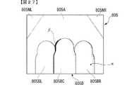
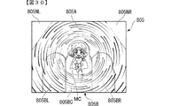
遊技を実行可能な遊技機(パチンコ遊技機801)であって、被投影領域(例えば、スクリーン805の平面表示領域805A及び立体表示領域805B)に対して斜め方向を向いた投影方向から画像を投影する投影手段(例えば、プロジェクタ832)を備え、前記投影手段から投影される画像の投影領域(例えば、投影領域805X)は、幅が広い幅広部(例えば、投影領域805Xにおける幅広部805XW)と、前記幅広部よりも幅が狭い幅狭部(例えば、投影領域805Xにおける幅狭部805XN)とがあり、前記投影領域における幅狭部の外の領域(例えば、非投影領域805NL,805NR)を発光させる発光手段(例えば、サブLED833)と、開放状態と閉鎖状態とに変化可能とされ、前記閉鎖状態のときに遊技領域を覆う開閉扉(扉枠850)と、をさらに備え、前記開閉扉が開放状態のときに、前記投影手段の投影を制限する制限手段(例えば、演出制御基板812における演出制御用CPU120)を備える
ことを特徴としている。
この特徴によれば、投影手段が投影できない領域があったとしても好適に演出を実行することができるとともに、遊技者に対する投影手段からの光の投射を抑制することができる。
The gaming machine of the means 15 of the present invention is the gaming machine according to any one of the means 8 to 14.
A gaming machine (pachinko gaming machine 801) capable of performing a game, and projects an image from a projection direction oriented obliquely with respect to a projected area (for example, a flat display area 805A and a stereoscopic display area 805B of the screen 805). The projection means (for example, the projector 832) is provided, and the projection area (for example, the projection area 805X) of the image projected from the projection means includes a wide portion (for example, the wide portion 805XW in the projection area 805X). There is a narrow portion narrower than the wide portion (for example, the narrow portion 805XN in the projection region 805X), and the region outside the narrow portion in the projection region (for example, the non-projection region 805NL, 805NR) emits light. The opening / closing door is further provided with a light emitting means (for example, a sub LED 833) and an opening / closing door (door frame 850) that can be changed between an open state and a closed state and covers the game area in the closed state. It is characterized in that it is provided with limiting means (for example, the effect control CPU 120 on the effect control board 812) that limits the projection of the projection means when in the open state.
According to this feature, even if there is a region where the projection means cannot project, the effect can be suitably executed, and the projection of light from the projection means to the player can be suppressed.

尚、上記の「斜め方向を向いた投影方向」とは、被投影領域に直交する軸と、投影手段から投影される投影光の光軸とが平行とならない方向をいう。また、「投影領域における幅狭部の外の領域を発光」には、投影領域における幅狭部の外の領域に対してLEDなどの光源から光を照射することによる発光や投影領域における幅狭部の外の領域を透光性材料で構成し、投影領域における幅狭部の外の領域の裏面側に光源を配置することによる発光が含まれる。 The above-mentioned "projection direction oriented in an oblique direction" means a direction in which the axis orthogonal to the projected region and the optical axis of the projected light projected from the projection means are not parallel to each other. In addition, "emission of a region outside the narrow portion in the projection region" includes light emission by irradiating a region outside the narrow portion in the projection region with light from a light source such as an LED or narrow width in the projection region. Light emission is included by arranging a light source on the back surface side of the region outside the narrow portion in the projection region by composing the region outside the portion with a translucent material.

本発明の手段16の遊技機は、手段15に記載の遊技機であって、
前記被投影領域は、前記投影手段によって投影される投影画像の投影領域よりも広くされて(例えば、スクリーン805の平面表示領域805A及び立体表示領域805Bは投影領域805Xよりも広くされて)いてもよい。
ことを特徴としている。
この特徴によれば、投影手段によって投影画像が投影される被投影領域及び発光手段によって発光される領域を含む被投影領域の全体において好適に演出を実行することができる。
The gaming machine of the means 16 of the present invention is the gaming machine according to the means 15.
The projected area may be wider than the projected area of the projected image projected by the projection means (for example, the planar display area 805A and the stereoscopic display area 805B of the screen 805 may be wider than the projected area 805X). Good.
It is characterized by that.
According to this feature, it is possible to suitably perform the effect in the entire projected region including the projected region on which the projected image is projected by the projection means and the region emitted by the light emitting means.

本発明の手段17の遊技機は、手段15または16に記載の遊技機であって、
前記被投影領域には凹凸部(例えば、スクリーン805の立体表示領域805B)が形成されており、所定の特定画像(例えば、飾り図柄、保留表示、保留数表示、今回表示の画像などの特定情報画像及び著名人の肖像やキャラクタなどの完全な表示が要望される画像である完全表示要望画像)は、前記凹凸部以外の領域(例えば、スクリーン805の平面表示領域または図26に示すサブ画像表示装置870)に表示されてもよい
ことを特徴としている。
この特徴によれば、特定画像の視認性の低下を抑制することができる。
The gaming machine of the means 17 of the present invention is the gaming machine according to the means 15 or 16.
An uneven portion (for example, a three-dimensional display area 805B of the screen 805) is formed in the projected area, and specific information such as a predetermined specific image (for example, a decorative pattern, a hold display, a hold number display, or an image displayed this time) is formed. The complete display request image, which is an image and an image for which complete display of a celebrity portrait or character is required, is a region other than the uneven portion (for example, a flat display region of the screen 805 or a sub-image display shown in FIG. It is characterized in that it may be displayed on the device 870).
According to this feature, it is possible to suppress a decrease in visibility of a specific image.

本発明の手段18の遊技機は、手段15〜17のいずれかに記載の遊技機であって、
前記投影手段から投影される投影光を前記被投影領域に向けて反射させる反射ミラー(例えば、反射ミラー828)を備え、前記反射ミラーは、所定の構造物(例えば、ロゴ役物826)の裏面側に設けられていてもよい
ことを特徴としている。
この特徴によれば、意匠性を損ねることなく反射ミラーを配置することができる。
The gaming machine of the means 18 of the present invention is the gaming machine according to any one of the means 15 to 17.
A reflection mirror (for example, a reflection mirror 828) that reflects the projected light projected from the projection means toward the projected region is provided, and the reflection mirror is a back surface of a predetermined structure (for example, a logo accessory 826). The feature is that it may be provided on the side.
According to this feature, the reflective mirror can be arranged without impairing the design.

本発明の手段19の遊技機は、手段15〜18のいずれかに記載の遊技機であって、
前記投影手段は、前記反射ミラーとともに前記構造物に対して投影光を投射する(例えば、プロジェクタ832から投影される投影光は、反射ミラー828の面積よりも広い範囲に投射されている)ようにしてもよい
ことを特徴としている。
この特徴によれば、投影光により被投影領域と構造物とに対する投影光の投影を行うことができ、他の投影手段を設ける場合よりも部品点数を減らすことができる。
The gaming machine of the means 19 of the present invention is the gaming machine according to any one of the means 15 to 18.
The projection means projects projected light onto the structure together with the reflective mirror (for example, the projected light projected from the projector 832 is projected over an area larger than the area of the reflective mirror 828). It is characterized by being acceptable.
According to this feature, the projected light can be projected onto the projected area and the structure, and the number of parts can be reduced as compared with the case where other projection means are provided.

本発明の手段20の遊技機は、手段15〜19のいずれかに記載の遊技機であって、
所定の作動条件が成立(例えば復活パターンを含むスーパーリーチ演出における第2段階を実行)したときに前記投影手段による投影が実行され、前記投影手段による画像の投影によって、遊技者に有利となる期待度が高いときに実行される特定演出(例えば、復活パターンを含むスーパーリーチ演出)を実行するものであり、前記作動条件の成立を待機する待機条件が成立(例えば、主基板811から送信された復活パターンを含むスーパーリーチ演出を実行する変動カテゴリコマンドを受信)したときに、前記投影手段の投影準備(例えば、プロジェクタ832の暖機運転)を行ってもよい
ことを特徴としている。
この特徴によれば、特定演出に関する画像を好適に投影することができる。
The gaming machine of the means 20 of the present invention is the gaming machine according to any one of the means 15 to 19.
When a predetermined operating condition is satisfied (for example, the second step in the super reach effect including the resurrection pattern is executed), the projection by the projection means is executed, and the projection of the image by the projection means is expected to be advantageous to the player. A specific effect (for example, a super reach effect including a resurrection pattern) that is executed when the degree is high is executed, and a standby condition that waits for the establishment of the operating condition is satisfied (for example, transmitted from the main board 811). When a variable category command for executing a super reach effect including a resurrection pattern is received), the projection preparation of the projection means (for example, warm-up operation of the projector 832) may be performed.
According to this feature, an image relating to a specific effect can be preferably projected.

本発明の手段21の遊技機は、手段15〜20のいずれかに記載の遊技機であって、
計時手段(例えば、演出制御基板812に設けられたRTC回路)による計時が所定の演出開始時間(例えば、RTC演出の開始時間)となったときに、前記投影手段による投影が実行され、前記投影手段による画像の投影によって、特別演出(例えば、RTC演出)を実行するものであり、実行条件の成立の所定時間前(例えば、RTC演出の開始時間よりもプロジェクタ832の暖機時間分の前の時間)となったときに、前記投影手段の投影準備(例えば、プロジェクタ832の暖機運転)を行ってもよい
ことを特徴としている。
この特徴によれば、特別演出に関する画像を好適に投影することができる。
The gaming machine of the means 21 of the present invention is the gaming machine according to any one of the means 15 to 20.
When the time measured by the time measuring means (for example, the RTC circuit provided on the effect control board 812) reaches a predetermined effect start time (for example, the start time of the RTC effect), the projection by the projection means is executed and the projection is performed. A special effect (for example, RTC effect) is executed by projecting an image by means, and a predetermined time before the establishment of the execution condition (for example, before the start time of the RTC effect for the warm-up time of the projector 832). When the time is reached, the projection preparation of the projection means (for example, warm-up operation of the projector 832) may be performed.
According to this feature, an image relating to a special effect can be preferably projected.

本発明の手段22の遊技機は、手段15〜21のいずれかに記載の遊技機であって、
前記投影手段による画像の投影によって所定演出(例えば、復活パターンを含むスーパーリーチ演出またはRTC演出)を実行するものであり、前記投影手段の作動温度と作動時間とのうち少なくともいずれか一方に応じて、前記所定演出の実行割合を異ならせ(例えば、プロジェクタ832を作動することにより、プロジェクタ832が故障する可能性が高くなる所定のしきい値温度を超える場合に、復活演出を含むスーパーリーチ演出の実行を中止し)てもよい
ことを特徴としている。
この特徴によれば、所定演出に関する画像を好適に投影することができる。
The gaming machine of the means 22 of the present invention is the gaming machine according to any one of the means 15 to 21.
A predetermined effect (for example, a super reach effect including a resurrection pattern or an RTC effect) is executed by projecting an image by the projection means, and it depends on at least one of the operating temperature and the operating time of the projection means. (For example, when the execution ratio of the predetermined effect exceeds a predetermined threshold temperature at which the projector 832 is more likely to fail by operating the projector 832, the super reach effect including the revival effect is produced. The feature is that the execution may be stopped).
According to this feature, an image relating to a predetermined effect can be preferably projected.

尚、本発明は、本発明の請求項に記載された発明特定事項のみを有するものであっても良いし、本発明の請求項に記載された発明特定事項とともに該発明特定事項以外の構成を有するものであっても良い。 In addition, the present invention may have only the invention-specific matters described in the claims of the present invention, or may have a configuration other than the invention-specific matters together with the invention-specific matters described in the claims of the present invention. It may have.

パチンコ遊技機を正面から見た正面図である。It is a front view which looked at the pachinko machine from the front. 遊技制御基板(主基板)の回路構成例を示すブロック図である。It is a block diagram which shows the circuit structure example of the game control board (main board). 遊技島を示す正面図である。It is a front view which shows the game island. 遊技島の内部構造を示す側断面図である。It is a side sectional view which shows the internal structure of a game island. パチンコ遊技機の構成を示す斜視図である。It is a perspective view which shows the structure of the pachinko game machine. パチンコ遊技機を示す背面図である。It is a rear view which shows the pachinko game machine. 遊技盤とガラス扉枠の構成を示す分解斜視図である。It is an exploded perspective view which shows the structure of a game board and a glass door frame. 図1のA−A断面図である。FIG. 1 is a sectional view taken along the line AA of FIG. (A)はガラス扉枠の背面右上部を示す斜視図、(B)は遊技盤の前面右上部を示す斜視図である。(A) is a perspective view showing the upper right part of the back surface of the glass door frame, and (B) is a perspective view showing the upper right part of the front surface of the game board. 図1のB−B断面図である。It is BB sectional view of FIG. (A)はガラス扉枠が閉鎖位置にある状態におけるエアダクト605を示す横断面図、(B)はガラス扉枠が開放位置にある状態におけるエアダクト605を示す横断面図である。(A) is a cross-sectional view showing the air duct 605 in the state where the glass door frame is in the closed position, and (B) is a cross-sectional view showing the air duct 605 in the state where the glass door frame is in the open position. 本発明の変形例1としての空気の取込構造を示す分解斜視図である。It is an exploded perspective view which shows the air intake structure as the modification 1 of this invention. (A)は図12のガラス窓の正面図、(B)は背面図、(C)は(B)のC−C断面図である。(A) is a front view of the glass window of FIG. 12, (B) is a rear view, and (C) is a sectional view taken along the line CC of (B). (A)は本発明の変形例2としての空気の取込構造を示すガラス窓の正面図、(B)は(A)のD−D断面図である。(A) is a front view of a glass window showing an air intake structure as a modification 2 of the present invention, and (B) is a cross-sectional view taken along the line DD of (A). 本発明の変形例3としての空気の取込構造を示すガラス扉枠の右側面図である。It is a right side view of the glass door frame which shows the air intake structure as the modification 3 of this invention. 本発明の変形例4としての空気の取込構造を示すガラス扉枠を斜め下方から見た状態を示す斜視図である。FIG. 5 is a perspective view showing a state in which a glass door frame showing an air intake structure as a modification 4 of the present invention is viewed from diagonally below. 実施例2におけるパチンコ遊技機の正面図である。It is a front view of the pachinko gaming machine in Example 2. 実施例2におけるパチンコ遊技機の側断面図である。It is a side sectional view of the pachinko gaming machine in Example 2. 実施例2におけるパチンコ遊技機の扉枠の斜視図である。It is a perspective view of the door frame of the pachinko gaming machine in Example 2. FIG. (A)は、立体表示領域に映像を投影したスクリーンの正面図、(B)は、立体表示領域に映像を投影していないスクリーンの正面図である。(A) is a front view of the screen on which the image is projected on the stereoscopic display area, and (B) is a front view of the screen on which the image is not projected on the stereoscopic display area. 各種の制御基板等を示す構成図である。It is a block diagram which shows various control boards and the like. 投影制限処理の手順を示すフローチャートである。It is a flowchart which shows the procedure of the projection restriction processing. 実施例3におけるパチンコ遊技機の正面図である。It is a front view of the pachinko gaming machine in Example 3. 実施例3におけるパチンコ遊技機の側断面図である。It is a side sectional view of the pachinko gaming machine in Example 3. ロゴ役物の側断面図である。It is a side sectional view of a logo accessory. 実施例4におけるパチンコ遊技機の側断面図である。It is a side sectional view of the pachinko gaming machine in Example 4. 変形例5を説明するためのスクリーンの正面図である。It is a front view of the screen for demonstrating the modification 5. 変形例6を説明するためのスクリーンの正面図である。It is a front view of the screen for demonstrating the modification 6. 変形例6を説明するためのパチンコ遊技機の側断面図である。It is a side sectional view of the pachinko gaming machine for demonstrating the modification 6. 変形例9を説明するためのスクリーンの正面図である。It is a front view of the screen for demonstrating the modification 9. 変形例10を説明するためのスクリーンの正面図である。It is a front view of the screen for demonstrating the modification 10. 変形例14,15を説明するためのスクリーンの正面図を用いた説明図である。It is explanatory drawing using the front view of the screen for demonstrating modified examples 14 and 15. 変形例21を説明するためのパチンコ遊技機の側断面図である。It is a side sectional view of the pachinko gaming machine for demonstrating the modification 21. 変形例21を説明するためのスクリーンの正面図である。It is a front view of the screen for demonstrating the modification 21. 変形例24を説明するためのスクリーンの正面図を用いた説明図である。It is explanatory drawing using the front view of the screen for demonstrating the modification 24.

本発明に係る遊技機を実施するための形態を実施例に基づいて以下に説明する。 A mode for carrying out the gaming machine according to the present invention will be described below based on examples.

まず、遊技機の一例であるパチンコ遊技機1の全体の構成について説明する。図1は、パチンコ遊技機を正面から見た正面図である。図2は、主基板における回路構成の一例を示すブロック図である。尚、以下において、図1の手前側をパチンコ遊技機1の前方(前面、正面)側、奥側を背面(後方)側とし、パチンコ遊技機1を前面側から見たときの上下左右方向を基準として説明する。尚、本実施例1におけるパチンコ遊技機1の前面とは、該パチンコ遊技機1にて遊技を行う遊技者と対向する対向面である。 First, the overall configuration of the pachinko gaming machine 1 which is an example of the gaming machine will be described. FIG. 1 is a front view of the pachinko gaming machine as viewed from the front. FIG. 2 is a block diagram showing an example of a circuit configuration on the main board. In the following, the front side of FIG. 1 is the front (front, front) side of the pachinko gaming machine 1, the back side is the back (rear) side, and the vertical and horizontal directions when the pachinko gaming machine 1 is viewed from the front side. It will be explained as a standard. The front surface of the pachinko gaming machine 1 in the first embodiment is a facing surface facing the player playing the game in the pachinko gaming machine 1.

図1は、本実施例1におけるパチンコ遊技機の正面図であり、主要部材の配置レイアウトを示す。パチンコ遊技機(以下、遊技機と略記する場合がある)1は、大別して、遊技盤面を構成する遊技盤(ゲージ盤)2と、遊技盤2を支持固定する遊技機用枠(台枠)3とから構成されている。遊技盤2には、ガイドレール2bによって囲まれた正面視略円形状の遊技領域10が形成されている。この遊技領域10には、遊技媒体としての遊技球が打球発射装置(図示略)から発射されて打ち込まれる。また、遊技機用枠3には、ガラス窓50aを有するガラス扉枠50が左側辺を中心として回動可能に設けられ、該ガラス扉枠50により遊技領域10を開閉できるようになっており、ガラス扉枠50を閉鎖したときにガラス窓50aを通して遊技領域10を透視できるようになっている。 FIG. 1 is a front view of the pachinko gaming machine according to the first embodiment, and shows the layout of the main members. The pachinko game machine (hereinafter, may be abbreviated as a game machine) 1 is roughly divided into a game board (gauge board) 2 constituting the game board surface and a game machine frame (underframe) for supporting and fixing the game board 2. It is composed of 3. The game board 2 is formed with a game area 10 having a substantially circular shape in front view surrounded by a guide rail 2b. A game ball as a game medium is launched from a ball striking device (not shown) into the gaming area 10. Further, the game machine frame 3 is provided with a glass door frame 50 having a glass window 50a so as to be rotatable around the left side, and the game area 10 can be opened and closed by the glass door frame 50. When the glass door frame 50 is closed, the game area 10 can be seen through the glass window 50a.

図1に示すように、遊技盤2は、アクリル樹脂、ポリカーボネート樹脂、メタクリル樹脂等の透光性を有する合成樹脂材にて正面見略四角形状に形成され、前面である遊技盤面に障害釘(図示略)やガイドレール2b、外レール飾り2D等が設けられた盤面板2Aと、該盤面板の背面側に一体的に取付けられるスペーサ部材2Bと、から主に構成されている。尚、遊技盤2はベニヤ板にて構成されていてもよい。 As shown in FIG. 1, the game board 2 is formed of a translucent synthetic resin material such as acrylic resin, polycarbonate resin, and methacrylic resin in a substantially square shape on the front surface, and an obstacle nail (obstacle nail) on the front surface of the game board. It is mainly composed of a board surface plate 2A provided with (not shown), a guide rail 2b, an outer rail decoration 2D, etc., and a spacer member 2B integrally attached to the back surface side of the board surface plate. The game board 2 may be made of plywood.

遊技盤2の所定位置(図1に示す例では、遊技領域10の右側下部位置)には、第1特別図柄表示器4Aと、第2特別図柄表示器4Bとが設けられている。第1特別図柄表示器4Aと第2特別図柄表示器4Bはそれぞれ、例えば7セグメントやドットマトリクスのLED(発光ダイオード)等から構成され、変動表示ゲームの一例となる特図ゲームにおいて、各々を識別可能な複数種類の識別情報(特別識別情報)である特別図柄(「特図」ともいう)が、変動可能に表示(変動表示または可変表示ともいう)される。以下では、第1特別図柄表示器4Aにおいて変動表示される特別図柄を「第1特図」ともいい、第2特別図柄表示器4Bにおいて変動表示される特別図柄を「第2特図」ともいう。 A first special symbol display 4A and a second special symbol display 4B are provided at a predetermined position of the game board 2 (in the example shown in FIG. 1, a lower right position of the game area 10). The first special symbol display 4A and the second special symbol display 4B are each composed of, for example, 7 segments or dot matrix LEDs (light emitting diodes), and are identified in a special symbol game which is an example of a variable display game. A special symbol (also referred to as a "special figure"), which is a plurality of types of possible identification information (special identification information), is displayed in a variable manner (also referred to as a variable display or a variable display). In the following, the special symbol that is variablely displayed on the first special symbol display 4A is also referred to as the "first special symbol", and the special symbol that is variablely displayed on the second special symbol display 4B is also referred to as the "second special symbol". ..

遊技盤2における遊技領域10の中央付近には、パチンコ遊技機1の前後方向に貫通する開口部2cが形成されており、開口部2cには、環状のステージ飾り枠51が嵌合されている。また、遊技盤2の後方には、後述する投影装置400(プロジェクタ)から投影される画像が投影されることによって、演出図柄の変動表示や、この演出図柄の変動表示に応じて実行される各種演出画像等が表示(投影)されるスクリーンユニット300が設けられており、該スクリーンユニット300を開口部2cを通して視認できるようになっている。 An opening 2c that penetrates the pachinko game machine 1 in the front-rear direction is formed near the center of the game area 10 in the game board 2, and an annular stage decorative frame 51 is fitted in the opening 2c. .. Further, by projecting an image projected from the projection device 400 (projector) described later on the rear of the game board 2, various types of display of variations in the effect symbol and various executions are performed in response to the variation display of the effect symbol. A screen unit 300 for displaying (projecting) an effect image or the like is provided, and the screen unit 300 can be visually recognized through the opening 2c.

スクリーンユニット300の被投影領域では、特図ゲームにおける第1特別図柄表示器4Aによる第1特図の変動表示や第2特別図柄表示器4Bによる第2特図の変動表示のそれぞれに対応して、例えば3つといった複数の変動表示部となる演出図柄表示エリアにて、各々を識別可能な複数種類の識別情報(装飾識別情報)である演出図柄が変動表示される。この演出図柄の変動表示も、変動表示ゲームに含まれる。 In the projected area of the screen unit 300, the variation display of the first special symbol by the first special symbol display 4A and the variation display of the second special symbol by the second special symbol display 4B in the special symbol game are supported. In the effect symbol display area, which is a plurality of variable display units such as three, the effect symbols, which are a plurality of types of identification information (decorative identification information) that can identify each of them, are variablely displayed. The variable display of this effect symbol is also included in the variable display game.

このように、スクリーンユニット300の被投影領域では、被投影領域に設定された「左」、「中」、「右」の演出図柄表示エリア5L,5C,5Rにて個々に演出図柄の変動表示が実行され、変動表示が終了するときに、「左」、「中」、「右」の各演出図柄表示エリア5L,5C,5Rにて、演出図柄の変動表示結果となる確定演出図柄(最終停止図柄)が停止表示される。このように、第1特別図柄表示器4Aにおける第1特図を用いた特図ゲーム、または、第2特別図柄表示器4Bにおける第2特図を用いた特図ゲームと同期して、各々が識別可能な複数種類の演出図柄の変動表示を行い、変動表示結果となる確定演出図柄を導出表示(あるいは単に「導出」ともいう)する。 In this way, in the projected area of the screen unit 300, the effect symbols are individually varied and displayed in the “left”, “middle”, and “right” effect symbol display areas 5L, 5C, and 5R set in the projected area. Is executed and when the variation display ends, the final effect symbol (final) that results in the variation display of the effect symbol in the "left", "middle", and "right" effect symbol display areas 5L, 5C, and 5R. Stop symbol) is displayed as stopped. In this way, in synchronization with the special figure game using the first special figure in the first special symbol display 4A or the special figure game using the second special figure in the second special symbol display 4B, each of them A variable display of a plurality of types of identifiable effect symbols is performed, and a definite effect symbol that is a variable display result is derived and displayed (or simply referred to as “deriving”).

スクリーンユニット300の被投影領域の下部の左右2箇所には、第1保留記憶表示エリア5D、第2保留記憶表示エリア5Uが設定されている。第1保留記憶表示エリア5D、第2保留記憶表示エリア5Uでは、特図ゲームに対応した変動表示の保留記憶数(特図保留記憶数)を特定可能に表示する保留記憶表示が行われる。 A first reserved storage display area 5D and a second reserved storage display area 5U are set at two locations on the left and right below the projected area of the screen unit 300. In the first hold storage display area 5D and the second hold storage display area 5U, the hold storage display for identifiablely displaying the hold storage number (special figure hold storage number) of the variable display corresponding to the special figure game is performed.

ここで、特図ゲームに対応した変動表示の保留は、普通入賞球装置6Aが形成する第1始動入賞口や、普通可変入賞球装置6Bが形成する第2始動入賞口を、遊技球が通過(進入)することによる始動入賞に基づいて発生する。すなわち、特図ゲームや演出図柄の変動表示といった変動表示ゲームを実行するための始動条件(「実行条件」ともいう)は成立したが、先に成立した開始条件に基づく変動表示ゲームが実行中であることやパチンコ遊技機1が大当り遊技状態に制御されていることなどにより、変動表示ゲームの開始を許容する開始条件が成立していないときに、成立した始動条件に対応する変動表示の保留が行われる。 Here, the holding of the variable display corresponding to the special figure game is such that the game ball passes through the first starting winning opening formed by the ordinary winning ball device 6A and the second starting winning opening formed by the ordinary variable winning ball device 6B. It occurs based on the starting prize by (entering). That is, the start condition (also referred to as "execution condition") for executing the variable display game such as the special figure game or the variable display of the effect symbol is satisfied, but the variable display game based on the previously established start condition is being executed. When the start condition that allows the start of the variable display game is not satisfied due to the fact that the pachinko game machine 1 is controlled to the jackpot game state, the variable display corresponding to the established start condition is suspended. Will be done.

第1特別図柄表示器4A及び第2特別図柄表示器4Bの右方位置には、特図保留記憶数を特定可能に表示するための第1保留表示器25Aと第2保留表示器25Bとが設けられている。第1保留表示器25Aは、第1特図保留記憶数を特定可能に表示し、第2保留表示器25Bは、第2特図保留記憶数を特定可能に表示する。 At the right position of the first special symbol display 4A and the second special symbol display 4B, there are a first hold display 25A and a second hold display 25B for identifiable display of the number of special symbol hold storages. It is provided. The first hold indicator 25A displays the number of first special figure hold storage identifiable, and the second hold indicator 25B displays the number of second special figure hold storage identifiable.

スクリーンユニット300の下方には、普通入賞球装置6Aが設けられ、スクリーンユニット300の右側下方には、普通可変入賞球装置6Bが設けられている。普通入賞球装置6Aは、例えば所定の球受部材によって常に一定の開放状態に保たれる始動領域(第1始動領域)としての第1始動入賞口を形成する。普通可変入賞球装置6Bは、図2に示す普通電動役物用となるソレノイド81によって、遊技領域10に突出する突出位置となる閉鎖状態と遊技領域10から退避する退避位置となる開放状態とに変化する可動板を有する普通電動役物を備え、始動領域(第2始動領域)としての第2始動入賞口を形成する。 A normal winning ball device 6A is provided below the screen unit 300, and a normal variable winning ball device 6B is provided below the right side of the screen unit 300. The ordinary winning ball device 6A forms a first starting winning opening as a starting region (first starting region) that is always kept in a constant open state by, for example, a predetermined ball receiving member. The normal variable winning ball device 6B is in a closed state in which it protrudes into the game area 10 and in an open state in which it is retracted from the game area 10 by the solenoid 81 for the normal electric accessory shown in FIG. It is provided with a normal electric accessory having a variable movable plate, and forms a second starting winning opening as a starting area (second starting area).

第1始動入賞口を通過(進入)した遊技球が第1始動口スイッチ22Aによって検出されたことに基づき、所定個数(例えば3個)の遊技球が賞球として払い出され、第1特図保留記憶数が所定の上限値(例えば「4」)以下であれば、第1始動条件が成立する。また、第2始動入賞口を通過(進入)した遊技球が第2始動口スイッチ22Bによって検出されたことに基づき、所定個数(例えば3個)の遊技球が賞球として払い出され、第2特図保留記憶数が所定の上限値(例えば「4」)以下であれば、第2始動条件が成立する。 Based on the fact that the game balls that have passed (entered) the first start winning opening are detected by the first starting opening switch 22A, a predetermined number (for example, 3) of game balls are paid out as prize balls, and the first special figure If the number of reserved storages is equal to or less than a predetermined upper limit value (for example, "4"), the first start condition is satisfied. Further, based on the fact that the game balls that have passed (entered) the second start winning opening are detected by the second starting opening switch 22B, a predetermined number (for example, 3) of game balls are paid out as prize balls, and the second If the number of reserved special figures is equal to or less than a predetermined upper limit value (for example, "4"), the second start condition is satisfied.

図1に示すように、普通入賞球装置6Aの右方位置には、特別可変入賞球装置7が設けられている。特別可変入賞球装置7は、図2に示す大入賞口扉用となるソレノイド82によって開閉駆動される大入賞口扉によって開放状態と閉鎖状態とに変化する特定領域としての大入賞口を形成する。このように、特定領域としての大入賞口は、遊技球が通過(進入)しやすく遊技者にとって有利な開放状態と、遊技球が通過(進入)できない(または通過(進入)しにくい)遊技者にとって不利な閉鎖状態とに変化する。 As shown in FIG. 1, a special variable winning ball device 7 is provided at a right position of the ordinary winning ball device 6A. The special variable winning ball device 7 forms a large winning opening as a specific area that changes between an open state and a closed state by the large winning opening door that is opened and closed and driven by the solenoid 82 for the large winning opening door shown in FIG. .. In this way, the large winning opening as a specific area is an open state in which the game ball is easy to pass (enter), which is advantageous for the player, and a player who cannot pass (enter) (or is difficult to enter) the game ball. It changes to a closed state that is disadvantageous for.

大入賞口を通過(進入)した遊技球が図2に示すカウントスイッチ23によって検出されたことに基づき、所定個数(例えば15個)の遊技球が賞球として払い出される。したがって、特別可変入賞球装置7において大入賞口が開放状態となれば、その大入賞口に遊技球が進入可能となり、遊技者にとって有利な第1の状態となる。その一方で、特別可変入賞球装置7において大入賞口が閉鎖状態となれば、大入賞口に遊技球を通過(進入)させて賞球を得ることが不可能または困難になり、遊技者にとって不利な第2の状態となる。 Based on the fact that the game balls that have passed (entered) the large prize opening are detected by the count switch 23 shown in FIG. 2, a predetermined number (for example, 15) of game balls are paid out as prize balls. Therefore, if the large winning opening is opened in the special variable winning ball device 7, the game ball can enter the large winning opening, which is a first state advantageous for the player. On the other hand, if the large winning opening is closed in the special variable winning ball device 7, it becomes impossible or difficult for the player to pass (enter) the game ball through the large winning opening to obtain the winning ball. It becomes a disadvantageous second state.

第2保留表示器25Bの右方位置には、普通図柄表示器20が設けられている。普通図柄表示器20の右方には、普図保留表示器25Cが設けられている。普図保留表示器25Cは、例えば4個のLEDを含んで構成され、通過ゲート41を通過した有効通過球数としての普図保留記憶数を表示する。 A normal symbol display 20 is provided at a position to the right of the second hold display 25B. On the right side of the normal symbol display 20, a normal symbol hold display 25C is provided. The normal figure hold indicator 25C is configured to include, for example, four LEDs, and displays the normal figure hold storage number as the number of effective passing balls that have passed through the passing gate 41.

遊技盤2の表面には、上記の構成以外にも、遊技球の流下方向や速度を変化させる風車及び多数の障害釘が設けられている。また、遊技領域10の最下方には、いずれの入賞口にも進入しなかった遊技球が取込まれるアウト口が設けられている。遊技機用枠3の左右上部位置には、効果音等を再生出力するためのスピーカ8L,8Rが設けられており、更に遊技領域10の周辺部には、演出用LED9が設けられている。遊技機用枠3の右下部位置には、遊技媒体としての遊技球を遊技領域10に向けて発射するために遊技者等によって操作される打球操作ハンドル(操作ノブ)が設けられている。 In addition to the above configuration, the surface of the game board 2 is provided with a windmill that changes the flow direction and speed of the game ball and a large number of obstacle nails. Further, at the lowermost part of the game area 10, an out port for taking in a game ball that has not entered any of the winning openings is provided. Speakers 8L and 8R for reproducing and outputting sound effects and the like are provided at the upper left and right positions of the game machine frame 3, and further, an effect LED 9 is provided at the peripheral portion of the game area 10. At the lower right position of the game machine frame 3, a ball striking operation handle (operation knob) operated by a player or the like to launch the game ball as a game medium toward the game area 10 is provided.

遊技領域10の下方における遊技機用枠3の所定位置には、賞球として払い出された遊技球や所定の球貸機により貸し出された遊技球を、発射装置(図示略)へと供給可能に保持(貯留)する上皿90(打球供給皿)が設けられている。遊技機用枠3の下部には、上皿90から溢れた余剰球などを、パチンコ遊技機1の外部へと排出可能に保持(貯留)する下皿91が設けられている。上皿90を形成する部材に設けられたプッシュボタン31Bに対してなされた押下動作はプッシュセンサ35Bにて検出される。 At a predetermined position of the game machine frame 3 below the game area 10, a game ball paid out as a prize ball or a game ball rented by a predetermined ball lending machine can be supplied to a launching device (not shown). An upper plate 90 (ball hitting plate) for holding (storing) the ball is provided. At the lower part of the gaming machine frame 3, a lower plate 91 is provided to hold (store) excess balls and the like overflowing from the upper plate 90 so that they can be discharged to the outside of the pachinko gaming machine 1. The pressing operation performed on the push button 31B provided on the member forming the upper plate 90 is detected by the push sensor 35B.

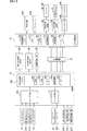
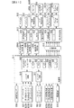
次に、パチンコ遊技機1の回路構成について説明する。パチンコ遊技機1には、例えば図2に示すような主基板11、演出制御基板12、音声制御基板13、LED制御基板14、主基板11と演出制御基板12との間で伝送される各種の制御信号を中継するための中継基板15、払出制御基板、情報端子基板、発射制御基板、インタフェース基板などといった、各種の基板が配置されている。 Next, the circuit configuration of the pachinko gaming machine 1 will be described. In the pachinko game machine 1, for example, as shown in FIG. 2, various types of transmissions are transmitted between the main board 11, the effect control board 12, the voice control board 13, the LED control board 14, the main board 11 and the effect control board 12. Various boards such as a relay board 15 for relaying a control signal, a payout control board, an information terminal board, a launch control board, and an interface board are arranged.

主基板11は、メイン側の制御基板であり、パチンコ遊技機1における遊技の進行を制御するための各種回路が搭載されている。主基板11は、主として、特図ゲームにおいて用いる乱数の設定機能、所定位置に配設されたスイッチ等からの信号の入力を行う機能、演出制御基板12などからなるサブ側の制御基板に宛てて、指令情報の一例となる制御コマンドを制御信号として出力して送信する機能、ホールの管理コンピュータに対して各種情報を出力する機能などを備えている。また、主基板11は、第1特別図柄表示器4Aと第2特別図柄表示器4Bを構成する各LED(例えばセグメントLED)などの点灯/消灯制御を行って第1特図や第2特図の変動表示を制御することや、普通図柄表示器20の点灯/消灯/発色制御などを行って普通図柄表示器20による普通図柄の変動表示を制御することといった、所定の表示図柄の変動表示を制御する機能も備えている。また、主基板11には、例えば遊技制御用マイクロコンピュータ100や、スイッチ回路110、ソレノイド回路111などが搭載されている。 The main board 11 is a control board on the main side, and is equipped with various circuits for controlling the progress of the game in the pachinko gaming machine 1. The main board 11 is mainly addressed to a sub-side control board including a function for setting a random number used in a special drawing game, a function for inputting a signal from a switch or the like arranged at a predetermined position, and an effect control board 12. , It has a function to output and transmit a control command as an example of command information as a control signal, and a function to output various information to the hall management computer. Further, the main board 11 controls lighting / extinguishing of each LED (for example, segment LED) constituting the first special symbol display 4A and the second special symbol display 4B to control the lighting / extinguishing of the first special symbol and the second special symbol. The variable display of a predetermined display symbol, such as controlling the variable display of the normal symbol 20 and controlling the variable display of the normal symbol by the normal symbol display 20 by controlling the lighting / extinguishing / coloring of the normal symbol display 20. It also has a control function. Further, for example, a game control microcomputer 100, a switch circuit 110, a solenoid circuit 111, and the like are mounted on the main board 11.

図2に示すように、主基板11には、通過ゲート41を通過した遊技球を検出するゲートスイッチ21、第1始動口スイッチ22A、第2始動口スイッチ22B、カウントスイッチ23からの検出信号を伝送する配線が接続されている。また、第1特別図柄表示器4A、第2特別図柄表示器4B、普通図柄表示器20、第1保留表示器25A、第2保留表示器25B、普図保留表示器25Cなどの表示制御を行うための指令信号を伝送する配線が接続されている。 As shown in FIG. 2, the main board 11 receives detection signals from the gate switch 21, the first start port switch 22A, the second start port switch 22B, and the count switch 23 that detect the game ball that has passed through the passing gate 41. The wiring to be transmitted is connected. In addition, display control of the first special symbol display 4A, the second special symbol display 4B, the normal symbol display 20, the first hold display 25A, the second hold display 25B, the normal figure hold display 25C, etc. is performed. The wiring that transmits the command signal for is connected.

主基板11から演出制御基板12に向けて伝送される制御信号は、例えば電気信号として送受信される演出制御コマンドである。演出制御コマンドには、例えば、演出図柄の変動時間及びリーチ演出の種類や擬似連の有無等の変動態様を示す変動パターンを示す変動パターン指定コマンド等が含まれている。 The control signal transmitted from the main board 11 to the effect control board 12 is, for example, an effect control command transmitted and received as an electric signal. The effect control command includes, for example, a variation pattern designation command indicating a variation pattern indicating a variation mode such as a variation time of the effect symbol, a type of reach effect, and the presence / absence of a pseudo-ream.

主基板11に搭載された遊技制御用マイクロコンピュータ100は、例えば1チップのマイクロコンピュータであり、遊技制御用のプログラムや固定データ等を記憶するROM101(ReadOnlyMemory101)と、遊技制御用のワークエリアを提供するRAM102(RandomAccessMemory102)と、遊技制御用のプログラムを実行して制御動作を行うCPU103(CentralProcessingUnit103)と、CPU103とは独立して乱数値を示す数値データの更新を行う乱数回路104と、I/O105(Input/Outputport105)と、を備えて構成される。一例として、遊技制御用マイクロコンピュータ100では、CPU103がROM101から読み出したプログラムを実行することにより、パチンコ遊技機1における遊技の進行を制御するための処理が実行される。 The game control microcomputer 100 mounted on the main board 11 is, for example, a one-chip microcomputer, and provides a ROM 101 (ReadOnlyMemory101) for storing a game control program, fixed data, and the like, and a work area for game control. RAM 102 (RandomAccessMemory102), a CPU 103 (CentralProcessingUnit103) that executes a game control program to perform control operations, a random number circuit 104 that updates numerical data indicating a random number value independently of the CPU 103, and an I / O 105. (Input / Output port 105) and. As an example, in the game control microcomputer 100, a process for controlling the progress of the game in the pachinko game machine 1 is executed by executing the program read from the ROM 101 by the CPU 103.

図2に示すように、演出制御基板12は、主基板11とは独立したサブ側の制御基板であり、中継基板15を介して主基板11から伝送された制御信号を受信して、投影装置400、スピーカ8L,8R、演出用LED9といった演出用の電気部品による演出動作を制御するための各種回路や、スティックコントローラ31A、プッシュボタン31Bといった電気部品の動作を検出するための各種回路が搭載されている。 As shown in FIG. 2, the effect control board 12 is a control board on the sub side independent of the main board 11, and receives a control signal transmitted from the main board 11 via the relay board 15 to receive a projection device. Various circuits for controlling the production operation by the production electric parts such as 400, speakers 8L, 8R, and production LED9, and various circuits for detecting the operation of the electric parts such as the stick controller 31A and the push button 31B are installed. ing.

演出制御基板12には、プログラムに従って制御動作を行う演出制御用CPU120と、演出制御用のプログラムや固定データ等を記憶するROM121と、演出制御用CPU120のワークエリアを提供するRAM122と、投影装置400における表示動作の制御内容を決定するための処理などを実行する表示制御部123と、演出制御用CPU120とは独立して乱数値を示す数値データの更新を行う乱数回路124と、I/O125とが搭載されている。一例として、演出制御基板12では、演出制御用CPU120がROM121から読み出した演出制御用のプログラムを実行することにより、演出用の電気部品による演出動作を制御するための処理が実行される。また、ROM121には、演出制御用のプログラムの他にも、演出動作を制御するために用いられる各種のデータテーブルなどが格納されている。 The effect control board 12 includes an effect control CPU 120 that performs control operations according to a program, a ROM 121 that stores an effect control program, fixed data, and the like, a RAM 122 that provides a work area for the effect control CPU 120, and a projection device 400. The display control unit 123 that executes processing for determining the control content of the display operation in the above, the random number circuit 124 that updates the numerical data indicating the random number value independently of the effect control CPU 120, and the I / O 125. Is installed. As an example, in the effect control board 12, the effect control CPU 120 executes the effect control program read from the ROM 121, thereby executing the process for controlling the effect operation by the effect electric components. Further, in the ROM 121, in addition to the effect control program, various data tables and the like used for controlling the effect operation are stored.

尚、本実施例1の投影装置400は、演出制御基板12の演出制御用CPU120により制御される。この演出制御用CPU120は、所定のプロセステーブルに基づいて投影装置400を含む各種装置類を制御して演出を実行するようにしている。そして、このプロセステーブルには、各種装置類を制御するためのプロセスデータ(投影装置400の表示制御を行うための表示制御実行データ、投影装置400の投影制御を行うための投影制御実行データの駆動制御を行うための駆動制御実行データ、スピーカ8L,8Rの音出力制御を行うための音出力制御実行データ等)が設定されている。 The projection device 400 of the first embodiment is controlled by the effect control CPU 120 of the effect control board 12. The effect control CPU 120 controls various devices including the projection device 400 based on a predetermined process table to execute the effect. Then, in this process table, process data for controlling various devices (display control execution data for performing display control of the projection device 400, and projection control execution data for performing projection control of the projection device 400) are driven. Drive control execution data for performing control, sound output control execution data for performing sound output control of the speakers 8L and 8R, etc.) are set.

尚、本実施例1では、ROM121に記憶された画像として、スクリーンユニット300において、投影対象となる各部位に対応付けられた画像、つまりプロジェクションマッピング技術により作成された画像を用いている。特に図示しないが、スクリーンユニット300が有するスクリーン301の前面には凹凸部(例えば、図7参照)が形成されており、投影装置400は、スクリーン301の凹凸部の形状に対応して作成された画像(いわゆるプロジェクションマッピング画像)を投影することが可能になっている。 In the first embodiment, as the image stored in the ROM 121, the image associated with each part to be projected in the screen unit 300, that is, the image created by the projection mapping technique is used. Although not particularly shown, an uneven portion (for example, see FIG. 7) is formed on the front surface of the screen 301 included in the screen unit 300, and the projection device 400 is created corresponding to the shape of the uneven portion of the screen 301. It is possible to project an image (so-called projection mapping image).

本実施例1では、スクリーンユニット300に合せて予めマッピングして画像を作成しておき、その画像データをROM121に記憶しておき、表示制御部123がROM121に記憶された画像データを読み出して、投影装置400を用いて出力するようにしているが、本発明はこれに限定されるものではなく、スクリーン301の形状に対応したマッピング済みの画像を予め作成しておくものでなくても良い。例えば、スクリーン301の形状に対応していない画像データと、スクリーン301の形状に合致させて画像をマッピングするための領域(座標)が記述されたマッピング用データをROM121に記憶しておき、表示制御部123がROM121に記憶された画像データとスクリーンに応じたマッピング用データとを読み出すとともに、その読み出した画像データをスクリーン301の形状に対応するようにリアルタイムにてマッピングして、このマッピングした画像をスクリーン301に投影装置400を用いて投影するようにしても良い。 In the first embodiment, an image is created by mapping in advance according to the screen unit 300, the image data is stored in the ROM 121, and the display control unit 123 reads out the image data stored in the ROM 121. Although the projection device 400 is used for output, the present invention is not limited to this, and it is not necessary to prepare a mapped image corresponding to the shape of the screen 301 in advance. For example, image data that does not correspond to the shape of the screen 301 and mapping data that describes an area (coordinates) for mapping an image that matches the shape of the screen 301 are stored in the ROM 121 for display control. The unit 123 reads out the image data stored in the ROM 121 and the mapping data according to the screen, maps the read image data in real time so as to correspond to the shape of the screen 301, and obtains the mapped image. The projection device 400 may be used for projection on the screen 301.

また、投影装置400の投影部401(レンズ)からスクリーンユニット300までの焦点距離が予め設定されたおり、投影装置400は、設定された焦点距離に応じて画像を投影するようにしている。 Further, the focal length from the projection unit 401 (lens) of the projection device 400 to the screen unit 300 is preset, and the projection device 400 projects an image according to the set focal length.

次に、パチンコ遊技機1における遊技の進行を概略的に説明する。パチンコ遊技機1では、遊技領域10に設けられた通過ゲート41を遊技球が通過したことに基づいて、普通図柄表示器20による普図ゲームが開始される。普通図柄の変動を開始させた後、普図変動時間となる所定時間が経過し、普図当り図柄以外の普通図柄が停止表示されれば、普通図柄の変動表示結果が「普図はずれ」となる。特定の普通図柄(普図当り図柄)が停止表示されれば、普通図柄の変動表示結果が「普図当り」となり、普通可変入賞球装置6Bの可動板が遊技領域10から退避する開放制御が行われ、所定時間が経過すると遊技領域10に突出する閉鎖位置に戻る通常開放制御が行われる。 Next, the progress of the game in the pachinko gaming machine 1 will be schematically described. In the pachinko gaming machine 1, based on the fact that the gaming ball has passed through the passing gate 41 provided in the gaming area 10, the normal symbol game by the normal symbol display 20 is started. After starting the fluctuation of the normal symbol, if the predetermined time that becomes the normal symbol fluctuation time elapses and the normal symbol other than the normal symbol per symbol is stopped and displayed, the fluctuation display result of the normal symbol is "out of normal symbol". Become. If a specific normal symbol (design per normal symbol) is stopped and displayed, the variable display result of the normal symbol becomes "per normal symbol", and the open control for retracting the movable plate of the normal variable winning ball device 6B from the game area 10 is performed. It is performed, and when a predetermined time elapses, a normal opening control is performed to return to the closed position protruding into the game area 10.

遊技球が第1始動入賞口に入賞したことなどにより第1始動条件が成立した後に、例えば前回の特図ゲームや大当り遊技状態が終了したことなどにより第1開始条件が成立したことに基づいて、第1特別図柄表示器4Aによる特図ゲームが開始される。また、遊技球が第2始動入賞口に入賞したことなどにより第2始動条件が成立した後に、例えば前回の特図ゲームや大当り遊技状態が終了したことなどにより第2開始条件が成立したことに基づいて、第2特別図柄表示器4Bによる特図ゲームが開始される。 Based on the fact that the first start condition is satisfied, for example, because the previous special figure game or the jackpot game state is completed, after the first start condition is satisfied because the game ball has won the first start winning opening. , The special symbol game by the first special symbol display 4A is started. In addition, after the second start condition is satisfied due to the game ball winning the second start winning opening, for example, the second start condition is satisfied due to the end of the previous special figure game or the jackpot game state. Based on this, the special symbol game by the second special symbol display 4B is started.

特図ゲームでは、特別図柄の変動表示を開始させた後、変動表示時間が経過すると確定特別図柄(特図表示結果)を導出表示する。このとき、特定の特別図柄(大当り図柄)が停止表示されれば、特定表示結果としての「大当り」となり、大当り図柄とは異なる特別図柄が停止表示されれば「はずれ」となる。特図ゲームでの変動表示結果が「大当り」になった後には、遊技者にとって有利なラウンド(「ラウンド遊技」ともいう)を所定回数実行する特定遊技状態としての大当り遊技状態に制御される。 In the special symbol game, after the variable display of the special symbol is started, the confirmed special symbol (special symbol display result) is derived and displayed when the variable display time elapses. At this time, if a specific special symbol (big hit symbol) is stopped and displayed, it becomes a "big hit" as a specific display result, and if a special symbol different from the big hit symbol is stopped and displayed, it becomes "missing". After the variable display result in the special figure game becomes a "big hit", the game is controlled to a big hit game state as a specific game state in which a round (also referred to as a "round game") advantageous to the player is executed a predetermined number of times.

大当り遊技状態においては、特別可変入賞球装置7の大入賞口扉が、所定の上限時間(例えば29秒間や0.1秒間)が経過するまでの期間あるいは所定個数(例えば9個)の入賞球が発生するまでの期間にて、大入賞口を開放状態とする。これにより、特別可変入賞球装置7を遊技者にとって有利な第1の状態(開放状態)とするラウンドが実行される。 In the big hit game state, the big winning door of the special variable winning ball device 7 is a period until a predetermined upper limit time (for example, 29 seconds or 0.1 seconds) elapses or a predetermined number (for example, 9) of winning balls. The big prize opening will be open until the occurrence of. As a result, a round is executed in which the special variable winning ball device 7 is set to the first state (open state) which is advantageous for the player.

ラウンドの実行中に大入賞口を開放状態とした大入賞口扉は、遊技盤2の表面を落下する遊技球を受け止め、その後に大入賞口を閉鎖状態とすることにより、特別可変入賞球装置7を遊技者にとって不利な第2の状態(閉鎖状態)に変化させて、1回のラウンドを終了させる。大入賞口の開放サイクルであるラウンドは、その実行回数が所定の上限回数(例えば「16」など)に達するまで、繰り返し実行可能となっている。 The large winning opening door that opens the large winning opening during the execution of the round catches the game ball falling on the surface of the game board 2, and then closes the large winning opening, so that the special variable winning ball device 7 is changed to a second state (closed state) which is disadvantageous to the player, and one round is completed. The round, which is the opening cycle of the big winning opening, can be repeatedly executed until the number of executions reaches a predetermined upper limit (for example, "16").

スクリーンユニット300の演出図柄表示エリア5L,5C,5Rでは、特図ゲームが開始されることに対応して、演出図柄の変動表示が開始される。そして、演出図柄の変動表示が開始されてから変動表示が終了するまでの期間では、演出図柄の変動表示状態が所定のリーチ状態となることがある。リーチ状態とは、スクリーンユニット300の被投影領域301Aにて停止表示された演出図柄が大当り組合せの一部を構成しているときに未だ停止表示されていない演出図柄については変動が継続している表示状態、あるいは、全部または一部の演出図柄が大当り組合せの全部または一部を構成しながら同期して変動している表示状態のことである。 In the effect symbol display areas 5L, 5C, and 5R of the screen unit 300, the variable display of the effect symbol is started in response to the start of the special figure game. Then, in the period from the start of the variable display of the effect symbol to the end of the variable display, the variable display state of the effect symbol may be in a predetermined reach state. The reach state means that when the effect symbols stopped and displayed in the projected area 301A of the screen unit 300 form a part of the jackpot combination, the effect symbols that are not yet stopped and displayed continue to fluctuate. It is a display state, or a display state in which all or part of the effect symbols are synchronously fluctuating while forming all or part of the jackpot combination.

特図ゲームにおける確定特別図柄として、複数種類の大当り組合せのうち、所定の通常大当り組合せ(「非確変大当り組合せ」ともいう)となる確定演出図柄が停止表示され、変動表示結果が「非確変大当り」となった場合は大当り状態に制御され、その終了後には、時間短縮制御(時短制御)が行われる。時短制御が行われることにより、特図ゲームにおける特別図柄の変動表示時間(特図変動時間)は、通常状態に比べて短縮される。尚、時短制御では、普通図柄の当選頻度が高められて、普通可変入賞球装置6Bへの入賞頻度が高められる、いわゆる電チューサポートが実施される。時短制御は、大当り遊技状態の終了後に所定回数(例えば100回)の特図ゲームが実行されることと、変動表示結果が「大当り」となることのうち、いずれかの条件が先に成立したときに、終了すればよい。 As a definite special symbol in the special symbol game, among a plurality of types of jackpot combinations, a definite effect symbol that is a predetermined normal jackpot combination (also referred to as "non-probability variable jackpot combination") is stopped and displayed, and the variable display result is "non-probable variable jackpot". If it becomes, the jackpot state is controlled, and after the end, the time reduction control (time reduction control) is performed. By performing the time reduction control, the fluctuation display time (special figure fluctuation time) of the special symbol in the special figure game is shortened as compared with the normal state. In the time saving control, the so-called electric chew support is carried out in which the winning frequency of the normal symbol is increased and the winning frequency of the normal variable winning ball device 6B is increased. In the time saving control, one of the conditions that the special figure game is executed a predetermined number of times (for example, 100 times) after the end of the big hit game state and that the variable display result becomes "big hit" is satisfied first. Sometimes you just have to quit.

特図ゲームにおける確定特別図柄として、複数種類の大当り組合せのうち、所定の確変大当り組合せ(「確変大当り組合せ」ともいう)となる確定演出図柄が停止表示され、変動表示結果が「確変大当り」となった場合は大当り状態に制御され、その終了後には、時短制御とともに確率変動制御(確変制御)が行われる。この確変制御が行われることにより、各回の特図ゲームにおいて変動表示結果が「大当り」となる確率は、通常状態に比べて高くなるように向上する。確変制御は、大当り遊技状態の終了後に変動表示結果が「大当り」となって再び大当り遊技状態に制御されるという条件が成立したとき、大当り遊技状態の終了後に所定回数(例えば時短回数と同じ100回)の特図ゲームが実行されたとき、大当り遊技状態の終了後に特図ゲームが開始されるごとに実行される確変転落抽選にて確変制御を終了させる「確変転落あり」の決定がなされたとき、などに終了すればよい。 As a definite special symbol in the special figure game, among a plurality of types of jackpot combinations, a definite effect symbol that is a predetermined probability variation jackpot combination (also referred to as "probability variation jackpot combination") is stopped and displayed, and the variable display result is "probability variation jackpot". If it becomes a big hit, it is controlled to a big hit state, and after the end, probability fluctuation control (probability variation control) is performed together with time reduction control. By performing this probability variation control, the probability that the variation display result becomes a "big hit" in each special figure game is improved so as to be higher than in the normal state. In the probability variation control, when the condition that the fluctuation display result becomes "big hit" and the game is controlled to the big hit game state again after the end of the big hit game state is satisfied, a predetermined number of times (for example, 100, which is the same as the time reduction number) after the end of the big hit game state When the special figure game of (times) is executed, it is decided that "there is a probability change fall" to end the probability change control by the probability change fall lottery that is executed every time the special figure game is started after the jackpot game state ends. When, etc., it should end.

時短制御が行われるときには、普図ゲームにおける普通図柄の変動時間(普図変動時間)を通常状態のときよりも短くする制御や、各回の普図ゲームで普通図柄の変動表示結果が「普図当り」となる確率を通常状態のときよりも向上させる制御、変動表示結果が「普図当り」となったことに基づく普通可変入賞球装置6Bにおける可動板の移動制御を行う移動制御時間を通常状態のときよりも長くする制御、その移動回数を通常状態のときよりも増加させる制御といった、遊技球が第2始動入賞口を通過(進入)しやすくして第2始動条件が成立する可能性を高めることで遊技者にとって有利となる制御(電チューサポート制御、高開放制御)が行われる。これにより、第2特図を用いた特図ゲームを実行するための第2始動条件が成立しやすくなり、特図ゲームが頻繁に実行可能となることで、次に変動表示結果が「大当り」となるまでの時間が短縮される。 When the time reduction control is performed, the fluctuation time of the normal symbol (normal symbol fluctuation time) in the normal diagram game is made shorter than that in the normal state, and the variation display result of the normal symbol in each normal diagram game is "normal diagram". Control to improve the probability of "hit" compared to the normal state, and the movement control time to control the movement of the movable plate in the normal variable winning ball device 6B based on the fact that the variable display result is "hit" There is a possibility that the second starting condition will be satisfied by making it easier for the game ball to pass (enter) the second starting winning opening, such as control to make it longer than in the state and control to increase the number of movements compared to the normal state. Controls that are advantageous to the player (electric chew support control, high open control) are performed by increasing the probability. This makes it easier to establish the second start condition for executing the special figure game using the second special figure, and the special figure game can be executed frequently, so that the variable display result is "big hit" next. The time until becomes is shortened.

次に、本実施例1におけるパチンコ遊技機1の動作(作用)を説明する。主基板11では、所定の電源基板からの電力供給が開始されると、遊技制御用マイクロコンピュータ100が起動し、CPU103によって遊技制御メイン処理となる所定の処理が実行される。遊技制御メイン処理において遊技制御用タイマ割込み処理を開始すると、スイッチ処理、メイン側エラー処理、情報出力処理、遊技用乱数更新処理、特別図柄プロセス処理、普通図柄プロセス処理、コマンド制御処理を実行する。 Next, the operation (action) of the pachinko gaming machine 1 in the first embodiment will be described. When the power supply from the predetermined power supply board is started on the main board 11, the game control microcomputer 100 is started, and the CPU 103 executes a predetermined process which is the game control main process. When the game control timer interrupt process is started in the game control main process, switch process, main side error process, information output process, game random number update process, special symbol process process, normal symbol process process, and command control process are executed.

特別図柄プロセス処理では、遊技制御フラグ設定部(図示略)に設けられた特図プロセスフラグの値をパチンコ遊技機1における遊技の進行状況に応じて更新し、第1特別図柄表示器4Aや第2特別図柄表示器4Bにおける表示動作の制御や、特別可変入賞球装置7における大入賞口の開閉動作設定などを、所定の手順で行うために各種の処理が選択されて実行される。 In the special symbol process processing, the value of the special symbol process flag provided in the game control flag setting unit (not shown) is updated according to the progress of the game in the pachinko gaming machine 1, and the first special symbol display 4A and the first 2 Various processes are selected and executed in order to control the display operation on the special symbol display 4B and set the opening / closing operation of the large winning opening in the special variable winning ball device 7 in a predetermined procedure.

特別図柄プロセス処理において、CPU103は、まず、第1始動入賞や第2始動入賞があったか否かを判定し、入賞があった場合には、特図表示結果判定用、大当り種別判定用、変動パターン判定用などの乱数値をそれぞれ抽出して、第1特図保留記憶部や第2特図保留記憶部における空きエントリの最上位に格納(記憶)する始動入賞処理を実行する。 In the special symbol process processing, the CPU 103 first determines whether or not there is a first start prize or a second start prize, and if there is a prize, the special symbol display result determination, the jackpot type determination, and the variation pattern. A start winning process is executed in which random values for determination and the like are extracted and stored (stored) at the highest level of empty entries in the first special figure reservation storage unit and the second special figure reservation storage unit.

また、CPU103は、第1特図保留記憶部や第2特図保留記憶部に記憶されている保留データの有無などに基づいて特図ゲームを開始するか否かの判定や、特図表示結果判定用の乱数値を示す数値データに基づき、特別図柄や演出図柄の変動表示結果を「大当り」とするか否かを、その変動表示結果が導出表示される前に決定(事前決定)する特別図柄通常処理を実行する。つまり、CPU103は、特図ゲームの変動表示を開始するときに、始動入賞が発生したときに記憶した乱数値に基づいて、当該変動表示の表示結果として大当り表示結果を導出表示するか否かを決定(抽選)する処理を実行する。 Further, the CPU 103 determines whether or not to start the special figure game based on the presence or absence of the hold data stored in the first special figure hold storage unit and the second special figure hold storage unit, and the special figure display result. Based on the numerical data indicating the random value for judgment, it is decided (predetermined) whether or not the variation display result of the special symbol or the effect symbol is a "big hit" before the variation display result is derived and displayed. Executes normal symbol processing. That is, when the CPU 103 starts the variable display of the special figure game, whether or not to derive and display the jackpot display result as the display result of the variable display based on the random number value stored when the start winning prize occurs. Execute the process of determining (lottery).

次いで、変動パターンを複数種類のいずれかに決定する変動パターン設定処理、特別図柄を変動させるための設定や特別図柄が変動を開始してからの経過時間を計測する処理を行う特別図柄変動処理、特別図柄の変動を停止させて確定特別図柄を停止表示(導出)させるための設定を行う特別図柄停止処理を行う。また、変動表示結果が「大当り」となった場合は、大当り遊技状態において大入賞口を開閉させる処理を行う大当り開放前処理、大当り開放中処理、大当り開放後処理、大当り終了処理を行う。 Next, a variation pattern setting process for determining the variation pattern to one of a plurality of types, a special symbol variation process for setting to change the special symbol and a process for measuring the elapsed time from the start of the variation of the special symbol, Stop the fluctuation of the special symbol and confirm it. Perform the special symbol stop processing to set the stop display (derivation) of the special symbol. When the variable display result is "big hit", the big hit opening pre-processing, the big hit opening processing, the big hit opening post-processing, and the big hit end processing are performed to open and close the big winning opening in the big hit game state.

次に、演出制御基板12の動作を説明する。先ず、演出制御用CPU120は、電源が投入されると、メイン処理の実行を開始する。メイン処理においてタイマ割込が発生すると、コマンド解析処理、演出制御プロセス処理、演出用乱数更新処理を実行する。 Next, the operation of the effect control board 12 will be described. First, the effect control CPU 120 starts executing the main process when the power is turned on. When a timer interrupt occurs in the main process, command analysis process, effect control process process, and effect random number update process are executed.

演出制御プロセス処理では、スクリーンユニット300の第1保留記憶表示エリア5D及び第2保留記憶表示エリア5Uでの保留記憶表示を、保留記憶バッファの記憶内容に応じた表示に更新する保留表示更新処理を実行する。次いで、演出制御プロセスフラグの値に応じて、遊技制御用マイクロコンピュータ100から変動パターン指定コマンドを受信しているか否か確認する変動パターン指定コマンド受信待ち処理、演出図柄の変動が開始されるように制御する演出図柄変動開始処理、演出図柄変動開始処理にてセットされたプロセスデータに応じて変動パターンを構成する各変動状態(変動速度)の切替タイミング等の制御や変動時間の終了を監視するとともに、投影装置400の表示制御、スピーカ8L,8Rからの音出力、演出用LED9の発光及び図示しない演出ユニット等の駆動制御等を行う演出図柄変動中処理、演出図柄の変動を停止し表示結果(停止図柄)を導出表示する制御を行う演出図柄変動停止処理を行う。 In the effect control process process, the hold display update process for updating the hold storage display in the first hold storage display area 5D and the second hold storage display area 5U of the screen unit 300 to the display according to the storage contents of the hold storage buffer is performed. Execute. Next, according to the value of the effect control process flag, the variation pattern specification command reception waiting process for confirming whether or not the variation pattern designation command is received from the game control microcomputer 100, and the variation of the effect symbol are started. In addition to controlling the switching timing of each fluctuation state (fluctuation speed) that composes the fluctuation pattern according to the process data set in the production symbol fluctuation start processing and the production symbol fluctuation start processing to be controlled, and monitoring the end of the fluctuation time. , Display control of the projection device 400, sound output from the speakers 8L and 8R, light emission of the effect LED 9 and drive control of the effect unit (not shown), etc. Processing during effect symbol change, stop the effect symbol change and display result ( Controls to derive and display the stop symbol) Performs the effect symbol fluctuation stop process.

大当り表示処理においては、変動時間の終了後、スクリーンユニット300の被投影領域301Aに大当りの発生を報知するための画面を表示する制御を行う。大当り遊技中処理においては、大当り遊技中の制御を行う。大当り終了演出処理においては、スクリーンユニット300の被投影領域301Aに大当り遊技状態が終了したことを遊技者に報知するための画面を表示する制御を行う。 In the jackpot display process, after the end of the fluctuation time, control is performed to display a screen for notifying the occurrence of the jackpot in the projected area 301A of the screen unit 300. In the processing during the big hit game, control is performed during the big hit game. In the jackpot end effect processing, control is performed to display a screen for notifying the player that the jackpot game state has ended in the projected area 301A of the screen unit 300.

このように演出制御用CPU120は、遊技制御用マイクロコンピュータ100から送信された演出制御コマンド(制御情報)に基づいて、演出図柄の変動表示制御や予告演出といった遊技に関連する各種演出を実行可能とされている。 In this way, the effect control CPU 120 can execute various game-related effects such as variable display control of the effect symbol and advance notice effect based on the effect control command (control information) transmitted from the game control microcomputer 100. Has been done.

尚、演出制御用CPU120が演出図柄の変動表示中において実行する予告演出としては、例えば、大当りの可能性を示唆する大当り予告演出や、リーチになるか否かを示唆するリーチ予告、停止図柄を予告する停止図柄予告、遊技状態が確率変動状態であるか否か(潜伏しているか否か)を予告する潜伏予告といったように、変動表示開始時やリーチ成立時において実行される複数の予告を含む。 As the notice effect to be executed by the effect control CPU 120 during the variable display of the effect symbol, for example, a jackpot notice effect suggesting the possibility of a big hit, a reach notice suggesting whether or not to reach, and a stop symbol are used. Multiple notices to be executed at the start of fluctuation display or when reach is established, such as a stop symbol notice to be announced and a latent notice to announce whether or not the game state is in a probability fluctuation state (whether or not it is hidden). Including.

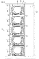
次に、図3及び図4に基づいて、パチンコ遊技機1を設置するための遊技島について説明する。図3は、遊技島を示す正面図である。図4は、遊技島の内部構造を示す側断面図である。尚、以下の説明において、説明の便宜上、図3の手前側を遊技島、遊技機、カードユニット、ユーティリティーユニットの前側、左右方向を左右側として説明する。つまり、遊技島の外側を遊技機の前側、内側を遊技機の後側(背面側)として説明する。 Next, a gaming island for installing the pachinko gaming machine 1 will be described with reference to FIGS. 3 and 4. FIG. 3 is a front view showing the game island. FIG. 4 is a side sectional view showing the internal structure of the game island. In the following description, for convenience of explanation, the front side of FIG. 3 will be described as the front side of the game island, the game machine, the card unit, and the utility unit, and the left-right direction will be described as the left-right side. That is, the outside of the game island will be described as the front side of the game machine, and the inside will be described as the rear side (rear side) of the game machine.

図3及び図4に示すように、本発明の実施例1としての遊技島501(遊技機設置島とも言う)は、例えば、遊技店(図示略)内に複数配設されている。遊技島501は、パチンコ遊技機1を左右方向に向けて複数設置可能に横長に構成され、その長手方向に延びる2つの立壁には、パチンコ遊技機1が設置される設置空間部SF,SBが長手方向に向けて形成されている。 As shown in FIGS. 3 and 4, a plurality of game islands 501 (also referred to as game machine installation islands) as the first embodiment of the present invention are arranged in, for example, a game store (not shown). The game island 501 is horizontally long so that a plurality of pachinko game machines 1 can be installed in the left-right direction, and the two standing walls extending in the longitudinal direction have installation space SFs and SBs in which the pachinko game machines 1 are installed. It is formed in the longitudinal direction.

尚、本実施例1のパチンコ遊技機1は、遊技島501の内部に設けられた供給樋540から遊技球の供給を受け、遊技の結果として払出した遊技球をパチンコ遊技機1の前側から排出可能であるとともに、遊技に使用された遊技球を該パチンコ遊技機1の背面側から排出可能とされている。 The pachinko gaming machine 1 of the first embodiment receives the supply of the gaming balls from the supply gutter 540 provided inside the gaming island 501, and discharges the gaming balls paid out as a result of the game from the front side of the pachinko gaming machine 1. It is possible, and the game ball used for the game can be discharged from the back side of the pachinko game machine 1.

各パチンコ遊技機1の左側方には、遊技者に対し遊技球の貸出を行うためのカードユニット506がパチンコ遊技機1と近接して配置されている。更に、各カードユニット506の左側方には、分煙装置、空気清浄器、灰皿等が設けられたユーティリティーユニット507がカードユニット506と近接して配置されている。また、各パチンコ遊技機1の右側方には、隣り合うパチンコ遊技機1の間に所定のスペースを確保するためのスペーサ508が配置されている。つまり、本実施例1における遊技島501においては、各パチンコ遊技機1に1対1に対応して、カードユニット506、ユーティリティーユニット507及びスペーサ508が各々配設されている。 On the left side of each pachinko gaming machine 1, a card unit 506 for lending a game ball to a player is arranged in close proximity to the pachinko gaming machine 1. Further, on the left side of each card unit 506, a utility unit 507 provided with a smoke separator, an air purifier, an ashtray, etc. is arranged in close proximity to the card unit 506. Further, on the right side of each pachinko gaming machine 1, a spacer 508 for securing a predetermined space between adjacent pachinko gaming machines 1 is arranged. That is, in the game island 501 in the first embodiment, the card unit 506, the utility unit 507, and the spacer 508 are arranged one-to-one with each pachinko gaming machine 1.

遊技島501は、床面Y上に設置されフレーム部材からなる躯体515の周面に腰板512F,512B、膳板513、設置板513a、幕板550及び遊技島501の長手方向の両端部の側板が取付けられることにより立壁が構成され、これら腰板512F,512B、膳板513、設置板513a、幕板550及び側板からなる立壁と上壁と床面Yとにより覆われた内部空間には、パチンコ遊技機1の関連設備等が配設される。 The game island 501 is provided on the peripheral surface of the skeleton 515 which is installed on the floor surface Y and is made of a frame member. A vertical wall is constructed by attaching the above, and a pachinko machine is provided in the internal space covered by the vertical wall consisting of the wainscots 512F, 512B, the table plate 513, the installation plate 513a, the curtain plate 550, and the side plates, the upper wall, and the floor surface Y. Equipment related to the game machine 1 and the like are arranged.

躯体515の上部には、遊技店員を呼出す呼出しスイッチ(図示略)を備えた呼出しランプ520が配置された幕板550が上辺を中心として開閉可能に取付けられている。この呼出しランプ520は、各パチンコ遊技機1に1対1に対応して設けられている。躯体515の下部には、木製の腰板512F,512B及びその上方に固定される設置板513aが取付けられるようになっており、該設置板513aの上面、つまり設置空間部SF,SBには、複数のパチンコ遊技機1が設置板513aの長手方向に沿って設置されるとともに、設置された各パチンコ遊技機1に対応してカードユニット506、ユーティリティーユニット507及びスペーサ508が設置される。 A curtain plate 550 on which a call lamp 520 equipped with a call switch (not shown) for calling a game clerk is arranged is attached to the upper part of the skeleton 515 so as to be openable and closable around the upper side. The calling lamp 520 is provided on each pachinko gaming machine 1 in a one-to-one correspondence. Wooden wainscots 512F and 512B and installation plates 513a fixed above them are attached to the lower part of the skeleton 515, and a plurality of wooden wainscots 512F and 512B are attached to the upper surface of the installation plates 513a, that is, the installation space SFs and SBs. The pachinko game machine 1 is installed along the longitudinal direction of the installation plate 513a, and the card unit 506, the utility unit 507, and the spacer 508 are installed corresponding to each of the installed pachinko game machines 1.

また、遊技島501の内部空間には、各パチンコ遊技機1に遊技球を補給するための補給通路を構成する供給樋540や補給シュート541及び各パチンコ遊技機1から排出された遊技に使用された遊技球を回収搬送する回収通路(図示略)が遊技島501の長手方向に向けて設置されている。回収通路(図示略)により回収された遊技球は、遊技島501の内部に設けられた揚送装置521及び揚送経路522を介して遊技球を貯留する上部タンク523まで搬送される。つまり、これら上部タンク523、供給樋540、補給シュート541、パチンコ遊技機1、回収通路(図示略)、揚送装置521及び揚送経路522は遊技球の循環経路を構成している。 Further, in the internal space of the game island 501, it is used for a supply gutter 540, a supply chute 541, and a game discharged from each pachinko game machine 1 which form a supply passage for supplying a game ball to each pachinko game machine 1. A collection passage (not shown) for collecting and transporting the game balls is installed in the longitudinal direction of the game island 501. The game balls collected by the collection passage (not shown) are conveyed to the upper tank 523 for storing the game balls via the lifting device 521 and the lifting path 522 provided inside the game island 501. That is, the upper tank 523, the supply gutter 540, the supply chute 541, the pachinko game machine 1, the collection passage (not shown), the lifting device 521, and the lifting route 522 form a circulation path for the game ball.

尚、供給樋540は、ステンレス製の板材にて形成され、遊技島501内におけるパチンコ遊技機1よりも上方位置において遊技球を遊技島501の長手方向に向けて流下可能に設けられており、遊技球を各パチンコ遊技機1へ流下により供給可能なように常に遊技球が滞留されている。 The supply gutter 540 is made of a stainless steel plate material, and is provided so that the game ball can flow down in the game island 501 at a position above the pachinko game machine 1 in the longitudinal direction of the game island 501. The game balls are always retained so that the game balls can be supplied to each pachinko game machine 1 by flowing down.

また、パチンコ遊技機1は、前面を遊技島501の外側、つまり、遊技者側に向けた状態で設置空間部SF,SBの所定位置に配置した状態で、後述する木製の外枠200から木製の設置板513aと設置板514に釘を打ち込むことにより固定される。 Further, the pachinko gaming machine 1 is made of wood from the wooden outer frame 200, which will be described later, in a state where the front surface is arranged at a predetermined position of the installation space SF and SB with the front surface facing the outside of the game island 501, that is, the player side. It is fixed by driving nails into the installation plate 513a and the installation plate 514.

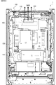
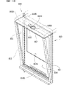
次に、図5〜図8に基づいて、パチンコ遊技機1の構造について説明する。図5は、パチンコ遊技機の構成を示す斜視図である。図6は、パチンコ遊技機を示す背面図である。図7は、遊技盤とガラス扉枠の構成を示す分解斜視図である。図8は、図1のA−A断面図である。 Next, the structure of the pachinko gaming machine 1 will be described with reference to FIGS. 5 to 8. FIG. 5 is a perspective view showing the configuration of a pachinko gaming machine. FIG. 6 is a rear view showing a pachinko gaming machine. FIG. 7 is an exploded perspective view showing the configuration of the game board and the glass door frame. FIG. 8 is a cross-sectional view taken along the line AA of FIG.

図5〜図8に示すように、パチンコ遊技機1は、四角枠状に形成される外枠200と、外枠200に対し左側辺を中心として回動可能に支持された遊技機用枠3と、遊技機用枠3に対し左側辺を中心として回動可能に支持されたガラス扉枠50と、から主に構成され、外枠200を介して遊技島501に固定されている。 As shown in FIGS. 5 to 8, the pachinko gaming machine 1 has an outer frame 200 formed in a square frame shape and a gaming machine frame 3 rotatably supported around the left side of the outer frame 200. It is mainly composed of a glass door frame 50 rotatably supported around the left side of the gaming machine frame 3, and is fixed to the gaming island 501 via an outer frame 200.

遊技機用枠3は、外枠200の左側辺を中心として、該外枠200の開口を閉鎖する閉鎖位置と開口を開放する開放位置との間で外枠200に回動可能に支持されており、遊技機用枠3を開放位置まで開放することで、外枠200を介して遊技島501の内部と外部とが連通する。また、ガラス扉枠50は、遊技機用枠3の左側辺を中心として該遊技機用枠3の前面を閉鎖する閉鎖位置と開口を開放する開放位置との間で遊技機用枠3に回動可能に支持されている。 The game machine frame 3 is rotatably supported by the outer frame 200 around the left side of the outer frame 200 between the closing position for closing the opening of the outer frame 200 and the opening position for opening the opening. By opening the gaming machine frame 3 to the open position, the inside and the outside of the game island 501 communicate with each other via the outer frame 200. Further, the glass door frame 50 is rotated to the game machine frame 3 between a closed position for closing the front surface of the game machine frame 3 and an open position for opening the opening around the left side of the game machine frame 3. It is movably supported.

遊技機用枠3には開口部160が形成されており、該開口部160を閉鎖するように遊技盤2を前方から着脱可能に取付けできるようになっている。遊技機用枠3に遊技盤2を取付けた状態でガラス扉枠50を閉鎖位置とすると、ガラス窓50aを通して遊技盤2に形成された遊技領域10及びスクリーンユニット300を透視できるようになっている。 An opening 160 is formed in the frame 3 for the game machine, and the game board 2 can be detachably attached from the front so as to close the opening 160. When the glass door frame 50 is in the closed position with the game board 2 attached to the game machine frame 3, the game area 10 and the screen unit 300 formed on the game board 2 can be seen through the glass window 50a. ..

パチンコ遊技機1の背面側、つまり、遊技機用枠3の背面上部には、遊技島501の供給樋540から補給シュート541を介して供給される遊技球を受ける球タンク150が設けられている。この球タンク150に供給された遊技球は、補給通路を流下して左側の払出装置に供給される。この払出装置から払い出された遊技球は、パチンコ遊技機1の前面に設けられた上皿90に誘導される。 On the back side of the pachinko gaming machine 1, that is, on the upper back side of the gaming machine frame 3, a ball tank 150 for receiving game balls supplied from the supply gutter 540 of the game island 501 via the supply chute 541 is provided. .. The game ball supplied to the ball tank 150 flows down the supply passage and is supplied to the payout device on the left side. The game ball paid out from the payout device is guided to the upper plate 90 provided on the front surface of the pachinko game machine 1.

遊技盤2の背面には、スクリーンユニット300、投影装置400及び演出用可動物(図示略)等が組付けられたカバー体220が取付けられている。カバー体220は、外部からの光の入射を遮ることができる遮光性部材により前面が開口する略箱状に形成され、遊技盤2の背面略全域を覆うように取付けられる。また、遊技盤2が遊技機用枠3に取付けられたときに開口部160を介して遊技機用枠3の背面側に突出するようになっている。 On the back surface of the game board 2, a cover body 220 to which a screen unit 300, a projection device 400, a movable object for production (not shown), and the like are assembled is attached. The cover body 220 is formed in a substantially box shape in which the front surface is opened by a light-shielding member capable of blocking the incident light from the outside, and is attached so as to cover substantially the entire back surface of the game board 2. Further, when the game board 2 is attached to the game machine frame 3, it projects to the back side of the game machine frame 3 through the opening 160.

カバー体220の背面には、主基板11が収納された主基板ケース11Aと、演出制御基板12が収納された演出基板ケース12Aと、遊技球の払出しに係わる制御を行う払出制御基板が収納された払出制御基板ケースと、パチンコ遊技機1に電力を供給するための電源基板(図示略)が収納された電源基板ケース(図示略)と、が設けられている。 On the back surface of the cover body 220, a main board case 11A in which the main board 11 is housed, an effect board case 12A in which the effect control board 12 is housed, and a payout control board that controls payout of game balls are housed. A payout control board case and a power supply board case (not shown) containing a power supply board (not shown) for supplying power to the pachinko gaming machine 1 are provided.

遊技盤2とカバー体220との間には、前述した投影装置400と、投影装置400から投影される映像を下後方に配置されるスクリーン301に向けて反射する反射板402と、スクリーンユニット300と、後述する取込部600から取込んだ空気を投影装置400へ誘導する第1エアダクト610、第2エアダクト620、第3エアダクト630、第4エアダクト640及び取込部600から空気を取込むためのファンユニット650とからなるエアダクト605が設けられている。 Between the game board 2 and the cover body 220, the above-mentioned projection device 400, a reflector 402 that reflects the image projected from the projection device 400 toward the screen 301 arranged at the lower rear side, and a screen unit 300. To take in air from the first air duct 610, the second air duct 620, the third air duct 630, the fourth air duct 640, and the intake unit 600 that guide the air taken in from the intake unit 600, which will be described later, to the projection device 400. An air duct 605 including the fan unit 650 of the above is provided.

スクリーンユニット300は、カバー体220に固定される支持体302と、支持体302に支持されるスクリーン301と、により構成される。尚、本実施例1では、支持体302はカバー体220に固定されているが、本発明はこれに限定されるものではなく、支持体302は遊技盤2のスペーサ部材2Bに固定されていてもよいし、カバー体220とスペーサ部材2Bとの双方に固定されていてもよい。 The screen unit 300 is composed of a support 302 fixed to the cover 220 and a screen 301 supported by the support 302. In the first embodiment, the support 302 is fixed to the cover 220, but the present invention is not limited to this, and the support 302 is fixed to the spacer member 2B of the game board 2. Alternatively, it may be fixed to both the cover body 220 and the spacer member 2B.

投影装置400は、支持体302の上部に、映像(光)を前方の反射板402へ向けて投影できるように投影部401を前向きにした状態で固定されている。また、投影装置400の筐体400Aの右側面には、ファンユニット650から供給される空気を取込む複数の吸気孔からなる吸気部410が設けられ、筐体400Aの左側面には、筐体400A内部の空気を排出する複数の排出孔からなる排気部411が設けられている。 The projection device 400 is fixed to the upper part of the support 302 with the projection unit 401 facing forward so that the image (light) can be projected toward the front reflector 402. Further, an intake unit 410 composed of a plurality of intake holes for taking in air supplied from the fan unit 650 is provided on the right side surface of the housing 400A of the projection device 400, and the housing is provided on the left side surface of the housing 400A. An exhaust unit 411 including a plurality of exhaust holes for exhausting the air inside the 400A is provided.

尚、本実施例1では、投影装置400は支持体302の上部に固定されているが、本発明はこれに限定されるものではなく、投影装置400はカバー体220または遊技盤2のスペーサ部材2Bに固定されていてもよいし、支持体302、カバー体220及びスペーサ部材2Bのうち少なくとも2つに固定されていてもよい。 In the first embodiment, the projection device 400 is fixed to the upper part of the support 302, but the present invention is not limited to this, and the projection device 400 is a spacer member of the cover body 220 or the game board 2. It may be fixed to 2B, or may be fixed to at least two of the support 302, the cover 220, and the spacer member 2B.

また、反射板402は、特に図示しないが支持体302に固定されている。よって、これら投影装置400、反射板402及びスクリーンユニット300は一体化された状態でカバー体220または遊技盤2のスペーサ部材2Bのうち少なくとも1つに固定されているため、投影装置400と反射板402とスクリーン301とが位置ずれしにくいようになっている。 Further, although not particularly shown, the reflector 402 is fixed to the support 302. Therefore, since the projection device 400, the reflector 402, and the screen unit 300 are fixed to at least one of the cover body 220 or the spacer member 2B of the game board 2 in an integrated state, the projection device 400 and the reflector The 402 and the screen 301 are less likely to be misaligned.

図7及び図8に示すように、遊技盤2の盤面板2Aにおける開口部2cの上部位置には、例えば、機種名やタイトルなどのロゴが表示された演出パネル310が配置されており、反射板402は、演出パネル310の背面側に重畳するように配置されている。演出パネル310は、内蔵された発光体により前面は発光するものの背面は非透光性部材にて構成されており、遊技者から反射板402を視認することが困難とされているため、目立つことがない。 As shown in FIGS. 7 and 8, for example, an effect panel 310 on which a logo such as a model name or a title is displayed is arranged at an upper position of the opening 2c in the board surface plate 2A of the game board 2, and is reflected. The plate 402 is arranged so as to overlap the back surface side of the effect panel 310. The effect panel 310 is conspicuous because the front surface emits light due to the built-in light emitting body, but the back surface is composed of a non-transmissive member, which makes it difficult for the player to visually recognize the reflector 402. There is no.

尚、本実施例1では、反射板402の前方に演出パネル310を配置することで反射板402の少なくとも一部が遊技者側から視認困難とされていたが、本発明はこれに限定されるものではなく、反射板402の前面に装飾を施すなどして演出部として遊技者から視認可能に設けてもよい。あるいは、演出パネル310の背面に反射部を設けて反射板を兼ねるようにしてもよい。 In the first embodiment, by arranging the effect panel 310 in front of the reflector 402, at least a part of the reflector 402 is difficult to see from the player side, but the present invention is limited to this. Instead, the front surface of the reflector 402 may be decorated so as to be visible to the player as a directing unit. Alternatively, a reflective portion may be provided on the back surface of the effect panel 310 to also serve as a reflector.

図8に示すように、カバー体220は、遊技盤2の背面を覆うように取付けられ、遊技盤2が遊技機用枠3に取付けられた状態において、遊技機用枠3や外枠200より一部が背面側に突出するように形成されている。よって、遊技機用枠3の前面がガラス扉枠50により閉鎖されると、スペーサ部材2Bとカバー体220とにより囲まれた空間S1と盤面板2Aとガラス窓50aとにより囲まれた空間S2(遊技領域10)とが開口部2cを介して連通して一の空間が形成される。 As shown in FIG. 8, the cover body 220 is attached so as to cover the back surface of the game board 2, and in a state where the game board 2 is attached to the game machine frame 3, the cover body 220 is attached to the game machine frame 3 and the outer frame 200. A part is formed so as to protrude to the back side. Therefore, when the front surface of the game machine frame 3 is closed by the glass door frame 50, the space S1 surrounded by the spacer member 2B and the cover body 220, the space S2 surrounded by the board plate 2A and the glass window 50a ( A space is formed by communicating with the game area 10) through the opening 2c.

投影装置400は、遊技盤2とカバー体220とにより囲まれた空間における上部背面側に配置され、その下方にはスクリーン301が配置されている。また、反射板402は、盤面板2Aに形成された開口部2cを介して少なくとも一部が盤面板2Aの前面よりも前側に突出するように配置されている。よって、反射板402を投影部401やスクリーン301から極力離れた位置に配置することができるため、スクリーン301の被投影領域301Aを大きくすることができる。 The projection device 400 is arranged on the upper back side in the space surrounded by the game board 2 and the cover body 220, and the screen 301 is arranged below the upper back side. Further, the reflector 402 is arranged so that at least a part thereof protrudes forward from the front surface of the board surface plate 2A through the opening 2c formed in the board surface plate 2A. Therefore, since the reflector 402 can be arranged at a position as far as possible from the projection unit 401 and the screen 301, the projected area 301A of the screen 301 can be increased.

また、投影装置400は、演出図柄の変動表示を行うため常時電源がオン状態とされるものであるため、ランプハウジングや筐体400Aが高温になりやすいため、内蔵されたファン(図示略)等により内部の熱気を後述する排気部411から強制的に排気できるようになっている。よって、カバー体220の背面における投影装置400に対応する位置に放熱用開口230が形成されていることで、投影装置400から排出された熱気が外部へ排出されるようになっている。尚、放熱用開口230は、図6及び図8に示すように、回路基板である主基板11が収納された主基板ケース11Aや演出制御基板12が収納された演出基板ケース12Aよりも上方位置に設けられており、放熱用開口230から排出された熱気は上昇するため、主基板11や演出制御基板12の制御回路が排出された熱気により温度上昇しないようにしている。 Further, since the projection device 400 is always in the power-on state for displaying the fluctuation of the effect pattern, the lamp housing and the housing 400A tend to have a high temperature, so that a built-in fan (not shown) or the like is used. As a result, the hot air inside can be forcibly exhausted from the exhaust unit 411, which will be described later. Therefore, since the heat dissipation opening 230 is formed on the back surface of the cover body 220 at a position corresponding to the projection device 400, the hot air discharged from the projection device 400 is discharged to the outside. As shown in FIGS. 6 and 8, the heat dissipation opening 230 is located above the main board case 11A in which the main board 11 which is a circuit board is housed and the effect board case 12A in which the effect control board 12 is housed. Since the hot air discharged from the heat dissipation opening 230 rises, the temperature of the control circuits of the main board 11 and the effect control board 12 is prevented from rising due to the discharged hot air.

図3、図4及び図8に示すように、遊技島501の立壁の一部を開放するように形成された設置空間部SF,SBに複数のパチンコ遊技機1が設置されることで、設置空間部SF,SBはパチンコ遊技機1により閉鎖され、遊技島501の内部と外部とが区画される。すなわち、遊技島501の内部も外部から閉ざされた空間とされている。 As shown in FIGS. 3, 4 and 8, a plurality of pachinko game machines 1 are installed in the installation space SFs and SBs formed so as to open a part of the standing wall of the game island 501. The space SF and SB are closed by the pachinko gaming machine 1, and the inside and the outside of the gaming island 501 are partitioned. That is, the inside of the game island 501 is also a space closed from the outside.

そして特に図8に示すように、設置空間部SF,SBにパチンコ遊技機1が設置された状態において、ガラス扉枠50の表面部(例えば、ガラス扉枠50の前面部、上面部、左右側面部及び下面部とガラス窓50aの前面部等を含む)は遊技島501の外側に面し、ガラス扉枠50の裏面(背面)側、つまり、パチンコ遊技機1の内側は遊技島501の内側に面することになる。すなわち、投影装置400が設けられた空間S1は、ガラス扉枠50の裏面側、つまり、パチンコ遊技機1の内側に位置しており、放熱用開口230を介して遊技島501の内部に連通している。 Then, as shown in FIG. 8, in a state where the pachinko gaming machine 1 is installed in the installation space SF and SB, the surface portion of the glass door frame 50 (for example, the front surface portion, the upper surface portion, and the left and right side surfaces of the glass door frame 50). The portion and the lower surface portion and the front portion of the glass window 50a, etc.) face the outside of the game island 501, and the back surface (rear surface) side of the glass door frame 50, that is, the inside of the pachinko game machine 1 is the inside of the game island 501. Will face. That is, the space S1 in which the projection device 400 is provided is located on the back surface side of the glass door frame 50, that is, inside the pachinko game machine 1, and communicates with the inside of the game island 501 through the heat dissipation opening 230. ing.

空間S1の熱気は、放熱用開口230から遊技島501内部へ排気されるものの、投影装置400、パチンコ遊技機1に設けられた各種装置や電子部品から放出される熱気が滞留しやすいため、投影装置400も高温になりやすい。そこで、空気により強制的に冷却することが考えられるが、空間S1の温度は比較的高く、また、遊技島501の内部も、複数のパチンコ遊技機1、揚送装置521や他の各種装置から放出される熱気により比較的高温であるため、好適に冷却するには限界がある。 Although the hot air in the space S1 is exhausted from the heat dissipation opening 230 to the inside of the game island 501, the hot air released from various devices and electronic components provided in the projection device 400 and the pachinko game machine 1 tends to stay, so that the hot air is projected. The device 400 also tends to get hot. Therefore, it is conceivable that the space S1 is forcibly cooled by air, but the temperature of the space S1 is relatively high, and the inside of the game island 501 is also from a plurality of pachinko game machines 1, a lifting device 521, and various other devices. Since the temperature is relatively high due to the hot air released, there is a limit to suitable cooling.

そこで本実施例1では、遊技島501の外部、つまり、遊技店内は空調機により温度調整されていることで、遊技島501の内部に比べて温度が低いため、パチンコ遊技機1に設けた取込部600から取込んだ遊技島501の外部の空気により投影装置400を強制的に冷却できるようになっている。 Therefore, in the first embodiment, since the temperature of the outside of the game island 501, that is, the inside of the game store is adjusted by the air conditioner, the temperature is lower than that of the inside of the game island 501. Therefore, the pachinko game machine 1 is provided with the temperature. The projection device 400 can be forcibly cooled by the air outside the game island 501 taken in from the inclusion portion 600.

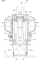
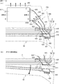
ここで、投影装置400を冷却するための空気の取込構造について、図9〜図11に基づいて説明する。図9は、(A)はガラス扉枠の背面右上部を示す斜視図、(B)は遊技盤の前面右上部を示す斜視図である。図10は、図1のB−B断面図である。図11は、(A)はガラス扉枠が閉鎖位置にある状態におけるエアダクト605を示す横断面図、(B)はガラス扉枠が開放位置にある状態におけるエアダクト605を示す横断面図である。 Here, the air intake structure for cooling the projection device 400 will be described with reference to FIGS. 9 to 11. 9A and 9B are a perspective view showing the upper right part of the back surface of the glass door frame, and FIG. 9B is a perspective view showing the upper right part of the front surface of the game board. FIG. 10 is a cross-sectional view taken along the line BB of FIG. 11A and 11B are a cross-sectional view showing an air duct 605 when the glass door frame is in the closed position, and FIG. 11B is a cross-sectional view showing the air duct 605 when the glass door frame is in the open position.

図9(A)、図10及び図11に示すように、ガラス扉枠50の上面50Hの右側には、空気の取込部600が設けられている。取込部600は、前後方向に延びる複数の長孔600Aが左右方向に並設されてなり、一の大きな孔部にて構成する場合に比べて異物等が進入し難くなっている。また、ガラス扉枠50の上面50Hに遊技者の荷物等が載置されることで一部の長孔600Aが塞がっても、他の長孔600Aから空気を取込むことができる。ガラス扉枠50の内部には、取込部600から下方に向けて第1エアダクト610が設けられている。ガラス扉枠50の背面50Bにおけるガラス窓50aの右上位置には、第1エアダクト610の下部に連通する横長長方形状の第1連通口611が形成されている。 As shown in FIGS. 9A, 10 and 11, an air intake portion 600 is provided on the right side of the upper surface 50H of the glass door frame 50. In the intake portion 600, a plurality of elongated holes 600A extending in the front-rear direction are arranged side by side in the left-right direction, so that foreign matter and the like are less likely to enter than in the case of being formed by one large hole portion. Further, even if a part of the elongated holes 600A is blocked by placing the player's luggage or the like on the upper surface 50H of the glass door frame 50, air can be taken in from the other elongated holes 600A. Inside the glass door frame 50, a first air duct 610 is provided downward from the intake portion 600. At the upper right position of the glass window 50a on the back surface 50B of the glass door frame 50, a horizontally long rectangular first communication port 611 communicating with the lower part of the first air duct 610 is formed.

一方、図9(B)、図10及び図11に示すように、遊技盤2の盤面板2Aにおける右側角部には前後に貫通する貫通孔622が形成されており、該貫通孔622には前後方向に延びる第2エアダクト620が設けられている。第2エアダクト620の前部は上方に屈曲しており、その前端には第2連通口621が形成されている。第2連通口621は、ガラス扉枠50側の第1連通口611に対応する位置に配置されている。 On the other hand, as shown in FIGS. 9B, 10 and 11, a through hole 622 penetrating back and forth is formed in the right corner portion of the board surface plate 2A of the game board 2, and the through hole 622 has a through hole 622. A second air duct 620 extending in the front-rear direction is provided. The front portion of the second air duct 620 is bent upward, and the second communication port 621 is formed at the front end thereof. The second communication port 621 is arranged at a position corresponding to the first communication port 611 on the glass door frame 50 side.

第2エアダクト620における第2連通口621の左右にはネジ穴621Aと位置決め突部621Bとがそれぞれ形成されている。また、第2連通口621の近傍からは下方に向けて取付片628が延設されており、盤面板2Aの前面に取付けられる外レール飾り2Dの上部にネジにより取付けられている。 Screw holes 621A and positioning protrusions 621B are formed on the left and right sides of the second communication port 621 in the second air duct 620, respectively. Further, a mounting piece 628 extends downward from the vicinity of the second communication port 621, and is mounted by a screw on the upper part of the outer rail decoration 2D mounted on the front surface of the board surface plate 2A.

第2連通口621には、フィルタ部材626とフィルタ押え627とがネジN1により取付けられる。詳しくは、フィルタ部材626は、枠部材626Aと、該枠部材626Aの開口を閉鎖するように設けられたフィルタ626Bと、ネジN1の取付孔626Cと、位置決め孔626Dと、を有する。フィルタ626Bは、ゴミや埃等の異物や煙草の煙に含まれるヤニ等の所定成分を捕捉可能な不織布、メッシュシート、網等で構成される。フィルタ押え627は、枠状に形成され、ネジN1の取付孔627Aと、位置決め孔627Bと、を有する。 A filter member 626 and a filter retainer 627 are attached to the second communication port 621 by screws N1. Specifically, the filter member 626 has a frame member 626A, a filter 626B provided so as to close the opening of the frame member 626A, a mounting hole 626C for the screw N1, and a positioning hole 626D. The filter 626B is composed of a non-woven fabric, a mesh sheet, a net, or the like that can capture a predetermined component such as a foreign substance such as dust or dirt and a tar contained in cigarette smoke. The filter retainer 627 is formed in a frame shape and has a mounting hole 627A for the screw N1 and a positioning hole 627B.

フィルタ押え627の背面側にフィルタ部材626を配置し、取付孔627A、取付孔626CにネジN1を背面側から取付け、位置決め孔627B、位置決め孔626Dを位置決め突部621Bに挿入して位置決めした状態でネジN1をネジ穴621Aに螺入することで、第2エアダクト620にフィルタ押え627を介してフィルタ部材626が取付けられ、第2連通口621がフィルタ626Bにより覆われる。 The filter member 626 is arranged on the back side of the filter retainer 627, the screw N1 is attached to the mounting hole 627A and the mounting hole 626C from the back side, and the positioning hole 627B and the positioning hole 626D are inserted into the positioning protrusion 621B for positioning. By screwing the screw N1 into the screw hole 621A, the filter member 626 is attached to the second air duct 620 via the filter retainer 627, and the second communication port 621 is covered with the filter 626B.

よって、ガラス扉枠50により遊技機用枠3の前面が閉鎖されることで、ガラス扉枠50の背面50Bにおける第1連通口611の周囲がフィルタ押え627の前面に当接し、第1連通口611及び第2連通口621を介して第1エアダクト610と第2エアダクト620とが連通する。一方、ガラス扉枠50が開放位置へ向けて回動して遊技機用枠3の前面が開放されることで、第1連通口611と第2連通口621とが離れて第1エアダクト610と第2エアダクト620とが分断されるようになっている。尚、フィルタ押え627は、例えば、軟質性を有する合成樹脂材またはゴム材にて構成されているので、ガラス扉枠50により遊技機用枠3が閉鎖されたときにガラス扉枠50の背面における第1連通口611の周囲にフィルタ押え627の前面が圧接されることで、空気の漏れが好適に防止される。 Therefore, by closing the front surface of the gaming machine frame 3 by the glass door frame 50, the periphery of the first communication port 611 on the back surface 50B of the glass door frame 50 comes into contact with the front surface of the filter retainer 627, and the first communication port The first air duct 610 and the second air duct 620 communicate with each other through the 611 and the second communication port 621. On the other hand, the glass door frame 50 rotates toward the open position to open the front surface of the gaming machine frame 3, so that the first communication port 611 and the second communication port 621 are separated from each other and the first air duct 610. The second air duct 620 is separated from the second air duct 620. Since the filter retainer 627 is made of, for example, a soft synthetic resin material or a rubber material, it is formed on the back surface of the glass door frame 50 when the gaming machine frame 3 is closed by the glass door frame 50. By pressing the front surface of the filter retainer 627 around the first communication port 611, air leakage is suitably prevented.

図10及び図11に示すように、第2エアダクト620の後端は、スペーサ部材2Bにおける貫通孔622に対応する位置に形成された凹部623に挿入されている。一方、スペーサ部材2Bの背面における凹部623に対応する位置には凹部625が形成されており、該凹部625には第3エアダクト630の前端が嵌合されている。そしてこれら凹部623と凹部625とを貫通するように貫通孔624が形成されていることで、該貫通孔624を介して第2エアダクト620と第3エアダクト630とが連通している。 As shown in FIGS. 10 and 11, the rear end of the second air duct 620 is inserted into a recess 623 formed at a position corresponding to the through hole 622 in the spacer member 2B. On the other hand, a recess 625 is formed on the back surface of the spacer member 2B at a position corresponding to the recess 623, and the front end of the third air duct 630 is fitted in the recess 625. Since the through hole 624 is formed so as to penetrate the recess 623 and the recess 625, the second air duct 620 and the third air duct 630 communicate with each other through the through hole 624.

尚、第2エアダクト620は、盤面板2Aに取付けられた外レール飾り2Dに取付けられているため、遊技盤2に一体化されているのに対し、第3エアダクト630及び第4エアダクト640とファンユニット650は、特に図示しないがカバー体220に取付けられているため、遊技盤2に対し離脱可能に設けられている。よって、遊技盤2からカバー体220を取外すことで、カバー体220とともに第3エアダクト630を遊技盤2から離脱させることができる。 Since the second air duct 620 is attached to the outer rail decoration 2D attached to the board surface plate 2A, it is integrated with the game board 2, whereas the third air duct 630 and the fourth air duct 640 and the fan are integrated. Since the unit 650 is attached to the cover body 220 (not shown), the unit 650 is provided so as to be detachable from the game board 2. Therefore, by removing the cover body 220 from the game board 2, the third air duct 630 can be separated from the game board 2 together with the cover body 220.

第3エアダクト630と第4エアダクト640との間にはファンユニット650が設けられている。また、第4エアダクト640の後端は、投影装置400の筐体400Aの右側面に形成された吸気部410を覆うように設けられている。よって、ダクト内に設けられたファン650Aを回転させることで、上流の取込部600側から下流の第4エアダクト640側へ向けて空気が流動するため、遊技島501の外部の空気を取込部600から吸引して投影装置400へ供給することが可能となる。 A fan unit 650 is provided between the third air duct 630 and the fourth air duct 640. Further, the rear end of the fourth air duct 640 is provided so as to cover the intake portion 410 formed on the right side surface of the housing 400A of the projection device 400. Therefore, by rotating the fan 650A provided in the duct, air flows from the upstream intake portion 600 side to the downstream fourth air duct 640 side, so that the air outside the game island 501 is taken in. It becomes possible to suck from the unit 600 and supply it to the projection device 400.

また、取込部600と投影装置400の吸気部410とは、第1エアダクト610、第2エアダクト620、第3エアダクト630、ファンユニット650及び第4エアダクト640からなる空気の取込経路であるエアダクト605を介して連通していることで、取込部600から取込んだ遊技島501の外部の冷たい空気を、パチンコ遊技機1の内部に触れさせることなく吸気部410へ送り込むことができる。 Further, the intake unit 600 and the intake unit 410 of the projection device 400 are air ducts that are air intake paths including a first air duct 610, a second air duct 620, a third air duct 630, a fan unit 650, and a fourth air duct 640. By communicating via the 605, the cold air outside the game island 501 taken in from the taking-in unit 600 can be sent to the intake unit 410 without touching the inside of the pachinko gaming machine 1.

また、エアダクト605は、取込部600側から投影装置400へ向けて漸次幅広となるように設けられている。また、エアダクト605は、取込部600から取込まれた空気を下方に誘導した後、後方へ向けて左側に誘導して投影装置400へ供給する、つまり、上下左右方向に蛇行する経路とされているとともに、ガラス扉枠50の裏面側から空間S1、S2内部に向けて延設されていることで、取込部600から不正に進入させた針金等の異物をカバー体220の背面側に設けられた主基板11や演出制御基板12まで到達させることが困難とされているため、不正行為を抑制できる。 Further, the air duct 605 is provided so as to gradually widen from the intake portion 600 side toward the projection device 400. Further, the air duct 605 is a path that guides the air taken in from the intake unit 600 downward and then guides it rearward to the left side to supply the air to the projection device 400, that is, a path meandering in the vertical and horizontal directions. In addition, since the glass door frame 50 extends from the back surface side toward the inside of the spaces S1 and S2, foreign matter such as a wire illegally entered from the intake portion 600 is placed on the back surface side of the cover body 220. Since it is difficult to reach the provided main board 11 and the effect control board 12, fraudulent acts can be suppressed.

また、エアダクト605は、遊技盤2の前側の取込部600から遊技盤2の後側の投影装置400へ向けて延設されることで、遊技盤2に形成された貫通孔622,624を挿通しているが、これら貫通孔622,624や第2連通口621は、遊技盤2における遊技領域10の外側に設けられていることで、遊技に支障をきたすことがない。また、ガラス扉枠50により遊技盤2の前面が閉鎖された状態において、ガラス扉枠50の枠状部の背面に位置し、ガラス窓50aを介して遊技者から視認不能となるため、エアダクト605が目立つことがない。 Further, the air duct 605 extends from the intake portion 600 on the front side of the game board 2 toward the projection device 400 on the rear side of the game board 2, so that the through holes 622 and 624 formed in the game board 2 are formed. Although they are inserted, the through holes 622, 624 and the second communication port 621 are provided outside the game area 10 of the game board 2, so that the game is not hindered. Further, when the front surface of the game board 2 is closed by the glass door frame 50, the air duct 605 is located behind the frame-shaped portion of the glass door frame 50 and cannot be seen by the player through the glass window 50a. Is not noticeable.

また、エアダクト605は、ガラス扉枠50側に設けられる第1エアダクト610からなる第1取込経路と、遊技機用枠3側に設けられる第2エアダクト620、第3エアダクト630、ファンユニット650及び第4エアダクト640からなる第2取込経路とを有し、ガラス扉枠50を閉鎖することにより第1取込経路と第2取込経路とが連通するようになっているので、取込部600やエアダクト605の一部がガラス扉枠50側に設けられていても、ガラス扉枠50の開閉に支障をきたすことがない。 Further, the air duct 605 includes a first intake path composed of a first air duct 610 provided on the glass door frame 50 side, a second air duct 620, a third air duct 630, a fan unit 650 and provided on the game machine frame 3 side. It has a second intake path composed of a fourth air duct 640, and by closing the glass door frame 50, the first intake path and the second intake path are communicated with each other. Even if a part of the 600 or the air duct 605 is provided on the glass door frame 50 side, the opening and closing of the glass door frame 50 is not hindered.

また、第1取込経路の第1連通口611と連通する第2連通口621にフィルタ626Bを有するフィルタ部材626が設けられているため、ガラス扉枠50の裏面側にある投影装置400内にゴミなどの異物が進入することを抑制できるとともに、ガラス扉枠50を開放することで、遊技者側にフィルタ部材626が露呈するので、フィルタ626Bのメンテナンス(例えば、フィルタ626Bに付着したゴミ等の掃除や、フィルタ部材626の交換作業など)を容易に行うことができる。 Further, since the filter member 626 having the filter 626B is provided at the second communication port 621 communicating with the first communication port 611 of the first intake path, the inside of the projection device 400 on the back surface side of the glass door frame 50 Foreign matter such as dust can be suppressed from entering, and by opening the glass door frame 50, the filter member 626 is exposed to the player side, so that maintenance of the filter 626B (for example, dust adhering to the filter 626B) can be prevented. Cleaning, replacement work of the filter member 626, etc.) can be easily performed.

尚、本実施例1では、フィルタ部材626は第2連通口621に取付けられていたが、本発明はこれに限定されるものではなく、フィルタ部材626は第1連通口611に取付けてもよいが、第1連通口611に取付けた場合はガラス扉枠50が回動するのに対し、第2連通口621に取付けた場合は遊技機用枠3が回動せず安定しているためメンテナンスの作業性が向上する。また、このような異物進入防止手段は、第1連通口611だけでなく、第2連通口621あるいは他の場所(例えば、エアダクト605の取込部600や他の位置や投影装置400の吸気部410など)に設けられていてもよい。さらに、複数個所に設けられていてもよい。 In the first embodiment, the filter member 626 is attached to the second communication port 621, but the present invention is not limited to this, and the filter member 626 may be attached to the first communication port 611. However, when it is attached to the first communication port 611, the glass door frame 50 rotates, whereas when it is attached to the second communication port 621, the gaming machine frame 3 does not rotate and is stable, so maintenance is performed. Workability is improved. Further, such a foreign matter intrusion prevention means is not limited to the first communication port 611, but also the second communication port 621 or another place (for example, the intake part 600 of the air duct 605, another position, or the intake part of the projection device 400). It may be provided in 410 etc.). Further, it may be provided at a plurality of places.

本実施例1の投影装置400は、装置の内部温度が第1温度(例えば、70度)に達したときに駆動が強制終了するものであり、投影装置400が第1温度よりも低い第2温度(例えば、40〜65度)に達したときにエラー処理(例えば、エラー音の出力、エラー表示など)を行うようになっているとともに、この第2温度を使用者が変更可能な機能を有している。よって、使用環境に応じた第2温度を使用者側で設定することができるため、駆動の強制終了を未然に防ぐための対策を施しやすくなる。 The projection device 400 of the first embodiment is forcibly terminated when the internal temperature of the device reaches the first temperature (for example, 70 degrees), and the projection device 400 is lower than the first temperature. When the temperature (for example, 40 to 65 degrees) is reached, error processing (for example, output of error sound, error display, etc.) is performed, and a function that allows the user to change this second temperature is provided. Have. Therefore, since the second temperature can be set on the user side according to the usage environment, it becomes easy to take measures to prevent the forced termination of the drive.

また、演出制御用CPU120は、例えば、投影装置400とは別個に設けた温度検知手段(図示略)から出力される信号の受信または投影装置400から出力される信号の受信に基づいて投影装置400の内部温度を監視しており、内部温度が第3温度に到達したときにファン650Aを回転させて投影装置400を冷却するため、投影装置400の温度上昇を抑制することができる。また、ファン650Aの駆動は、所定の終了条件(例えば、内部温度が第3温度未満となったこと、ファン650Aの駆動を開始してから所定期間が経過したことなど)が成立したことで停止する。尚、この場合、第3温度を第2温度と同一にしてもよいし、異なる温度としてもよい。 Further, the effect control CPU 120 is, for example, based on the reception of a signal output from the temperature detecting means (not shown) provided separately from the projection device 400 or the reception of the signal output from the projection device 400. Since the fan 650A is rotated to cool the projection device 400 when the internal temperature reaches the third temperature, the temperature rise of the projection device 400 can be suppressed. Further, the driving of the fan 650A is stopped when a predetermined end condition (for example, the internal temperature becomes less than the third temperature, a predetermined period has elapsed since the driving of the fan 650A was started, etc.) is satisfied. To do. In this case, the third temperature may be the same as the second temperature, or may be different.

また、本実施例1では、投影装置400の内部温度が第3温度に到達したときに演出制御用CPU120がファン650Aを回転させて投影装置400を冷却するようになっていたが、本発明はこれに限定されるものではなく、演出制御用CPU120は、投影装置400の内部温度に関わらずファン650Aを常時または所定パターンで駆動するようにしてもよいし、あるいは、空間S1の内部温度に基づいて駆動させるようにしてもよい。 Further, in the first embodiment, when the internal temperature of the projection device 400 reaches the third temperature, the effect control CPU 120 rotates the fan 650A to cool the projection device 400. However, in the present invention, the projection device 400 is cooled. The effect control CPU 120 is not limited to this, and the fan 650A may be driven at all times or in a predetermined pattern regardless of the internal temperature of the projection device 400, or based on the internal temperature of the space S1. It may be driven by.

以上説明したように、本発明の実施例1としてのパチンコ遊技機1にあっては、パチンコ遊技機1を設置可能な遊技島501に設置した状態において該遊技島501の外側に面する表面部(例えば、ガラス扉枠50の上面50H)と、映像が投影される被投影部材としてのスクリーン301と、スクリーン301に映像を投影する投影手段としての投影装置400と、を備え、ガラス扉枠50の上面50Hには、投影装置400を冷却するために遊技島501の外側から空気を取込むための取込部600が設けられていることで、遊技島501の外側の冷たい空気を取込部600から取込むことができるため、投影装置400により高温になりやすいガラス扉枠50の内側、つまり、パチンコ遊技機1の内部に設けられた投影装置400を好適に冷却することができる。 As described above, in the pachinko game machine 1 as the first embodiment of the present invention, the surface portion facing the outside of the game island 501 when the pachinko game machine 1 is installed on the game island 501 where the pachinko game machine 1 can be installed. (For example, the upper surface 50H of the glass door frame 50), a screen 301 as a projected member on which an image is projected, and a projection device 400 as a projection means for projecting an image on the screen 301 are provided. The upper surface 50H of the above surface is provided with an intake portion 600 for taking in air from the outside of the game island 501 in order to cool the projection device 400, so that the cold air intake portion outside the game island 501 is taken in. Since it can be taken in from 600, it is possible to suitably cool the projection device 400 provided inside the glass door frame 50, that is, inside the pachinko game machine 1, which tends to be heated by the projection device 400.

また、取込部600は遊技盤2の前側に設けられ、投影装置400が遊技盤2の後側に配設されているが、取込部600と投影装置400とは遊技盤2を貫通するエアダクト605(取込経路)により連通されていることで、取込部600から取込んだ空気を空間S1,S2内の空気に触れさせずに投影装置400へ供給できるため、投影装置400を好適に冷却することができるとともに、取込部600に進入させた異物を空間S1におけるエアダクト605外へ進入させることを困難とすることができる。 Further, the capture unit 600 is provided on the front side of the game board 2, and the projection device 400 is arranged on the rear side of the game board 2, but the capture unit 600 and the projection device 400 penetrate the game board 2. The projection device 400 is suitable because the air taken in from the intake unit 600 can be supplied to the projection device 400 without coming into contact with the air in the spaces S1 and S2 by being communicated by the air duct 605 (take-in path). It is possible to cool the air duct to the outside of the air duct 605 in the space S1 and make it difficult for the foreign matter that has entered the intake unit 600 to enter the air duct 605.

尚、本実施例では、エアダクト605は遊技盤2を貫通するように設けられていたが、本発明はこれに限定されるものではなく、取込部600から遊技盤2を迂回して背面側の投影装置400へ延設されていてもよい。 In the present embodiment, the air duct 605 is provided so as to penetrate the game board 2, but the present invention is not limited to this, and the intake unit 600 bypasses the game board 2 to the back side. It may be extended to the projection device 400 of.

また、取込部600は、ガラス扉枠50の上部である上面50Hに設けられていることで、遊技者から見え難くなり目立たない場所にあるので、ゴミやジュース等の液体を進入させるといったいたずら等を抑制できる。尚、上面50Hでなくても、例えば、ガラス扉枠50の前面に形成された凸部の周面に形成されていれば目立たなくなる。 Further, since the intake portion 600 is provided on the upper surface 50H, which is the upper part of the glass door frame 50, it is difficult for the player to see and is in an inconspicuous place, so that it is a mischief such as allowing liquids such as dust and juice to enter. Etc. can be suppressed. Even if the upper surface is not 50H, it will not be noticeable if it is formed on the peripheral surface of the convex portion formed on the front surface of the glass door frame 50, for example.

また、本実施例では、上下方向に延びる第1エアダクト610に対し前後方向に延びる第2エアダクト620が側面視略L字形に連結されているため、取込部600からゴミやジュース等の液体を進入された場合でも投影装置400までゴミや液体が進入し難くなっている。さらに、例えば、第1エアダクト610の下面に液体を貯留可能な空間等を設けることで、空気を漏らさずに液体の第2エアダクト620への進入を抑制することができる。 Further, in this embodiment, since the second air duct 620 extending in the front-rear direction is connected to the first air duct 610 extending in the vertical direction in a substantially L-shape in the side view, liquids such as dust and juice can be taken from the intake portion 600. Even if it has entered, it is difficult for dust and liquid to enter the projection device 400. Further, for example, by providing a space or the like capable of storing the liquid on the lower surface of the first air duct 610, it is possible to suppress the entry of the liquid into the second air duct 620 without leaking air.

また、ガラス扉枠50の裏面側に配置され該ガラス扉枠50を開閉可能に支持する遊技機用枠3と、ガラス扉枠50の裏面側に配置され取込部600から空気を取込むための取込手段としてのファンユニット650)と、取込部600から取込まれた空気をファンユニット650まで誘導する取込経路としてのエアダクト605に設けられる異物進入防止手段としてのフィルタ626Bと、を備え、エアダクト605は、ガラス扉枠50側に設けられる第1取込経路としての第1エアダクト610と遊技機用枠3側に設けられる第2取込経路としての第2エアダクト620、第3エアダクト630及び第4エアダクト640とを有し、ガラス扉枠50を開放することにより第1エアダクト610と第2エアダクト620、第3エアダクト630及び第4エアダクト640との連通が解除されるものであり、フィルタ626Bは、第2エアダクト620における第1エアダクト610との連通部である第1連通口611と連通する第2連通口621に設けられている。 Further, in order to take in air from the game machine frame 3 arranged on the back surface side of the glass door frame 50 and supporting the glass door frame 50 so as to be openable and closable, and the intake portion 600 arranged on the back surface side of the glass door frame 50. The fan unit 650) as a means for taking in the air, and the filter 626B as a means for preventing foreign matter from entering the air duct 605 as a taking path for guiding the air taken in from the taking-in unit 600 to the fan unit 650. The air duct 605 includes a first air duct 610 as a first intake path provided on the glass door frame 50 side, and a second air duct 620 and a third air duct as a second intake path provided on the game machine frame 3 side. It has 630 and 4th air duct 640, and by opening the glass door frame 50, the communication between the 1st air duct 610 and the 2nd air duct 620, the 3rd air duct 630 and the 4th air duct 640 is released. The filter 626B is provided at the second communication port 621 that communicates with the first communication port 611, which is a communication portion with the first air duct 610 in the second air duct 620.

これによれば、ガラス扉枠50の裏面側にゴミなどの異物が進入することを抑制できるとともに、ガラス扉枠50を開放することでフィルタ626Bのメンテナンス(例えば、表面についたゴミや塵を除去したりフィルタ部材626を交換する作業等を容易に行うことができる。 According to this, it is possible to prevent foreign matter such as dust from entering the back surface side of the glass door frame 50, and maintenance of the filter 626B (for example, removing dust and dirt on the front surface) by opening the glass door frame 50. The work of replacing the filter member 626 or the glass member 626 can be easily performed.

また、第1取込経路と第2取込経路との連通部である第1連通口611及び第2連通口621は、遊技盤2における遊技領域10外に設けられ、かつ、ガラス窓50aから視認できない位置に設けられているため、ガラス扉枠50を閉鎖したときに連通部が遊技者から目立たないため、不正行為を抑制できる。 Further, the first communication port 611 and the second communication port 621, which are the communication portions between the first intake path and the second intake path, are provided outside the game area 10 in the game board 2 and are provided from the glass window 50a. Since it is provided at a position where it cannot be visually recognized, the communication portion is inconspicuous from the player when the glass door frame 50 is closed, so that fraudulent activity can be suppressed.

また、ガラス扉枠50の裏面側、つまり、空間S1の空気を遊技島501の内部に排出可能であり、遊技島501の内部に排出する際に、放熱用開口230から、パチンコ遊技機1に設けられた主基板11や演出制御基板12とは異なる上方向へ排出することで、主基板11や演出制御基板12が排出した空気の熱により動作異常(例えば、熱暴走など)を起こすことを抑制できる。 Further, the back side of the glass door frame 50, that is, the air in the space S1 can be discharged to the inside of the game island 501, and when the air is discharged to the inside of the game island 501, the heat dissipation opening 230 is sent to the pachinko game machine 1. By discharging in an upward direction different from the provided main board 11 and effect control board 12, an operation abnormality (for example, thermal runaway) may occur due to the heat of the air discharged from the main board 11 and effect control board 12. Can be suppressed.

また、遊技島501の内部には、設置されたパチンコ遊技機1に遊技球を供給するための供給経路の一部である供給樋540がパチンコ遊技機1の上方に設けられ(図4参照)、空間S1の空気を遊技島501の内部に排出可能であり、遊技島501の内部に排出する際に、放熱用開口230から上方向、つまり、上方の供給樋540へ向けて排出することで、排出した空気の熱を利用して供給樋540を温めることができるため、該供給樋540の遊技球が結露することを好適に抑制することができる。 Further, inside the game island 501, a supply gutter 540, which is a part of a supply path for supplying a game ball to the installed pachinko game machine 1, is provided above the pachinko game machine 1 (see FIG. 4). , The air in the space S1 can be discharged to the inside of the game island 501, and when the air is discharged to the inside of the game island 501, it is discharged upward from the heat dissipation opening 230, that is, toward the upper supply gutter 540. Since the supply gutter 540 can be heated by utilizing the heat of the discharged air, it is possible to preferably suppress the dew condensation of the game balls of the supply gutter 540.

また、投影装置400の制御部(図示略)は、投影装置400が第1温度(例えば、70度)に達したときに駆動が強制終了するものであり、投影装置400が前記第1温度よりも低い第2温度(例えば、40〜65度)に達したときにエラー処理を行うようになっており、この第2温度を使用者が変更可能な機能を有していることで、使用環境に応じた第2温度を使用者側で設定することができるため、駆動の強制終了を未然に防ぐための対策を施しやすくなる。 Further, the control unit (not shown) of the projection device 400 is forcibly terminated when the projection device 400 reaches the first temperature (for example, 70 degrees), and the projection device 400 starts from the first temperature. Error processing is performed when a low second temperature (for example, 40 to 65 degrees) is reached, and the user can change this second temperature, so that the usage environment Since the second temperature can be set on the user side according to the above, it becomes easy to take measures to prevent the forced termination of the drive.

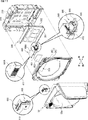
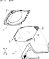
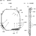
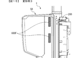
次に、本発明の変形例1〜5について、図12〜図16に基づいて説明する。図12は、本発明の変形例1としての空気の取込構造を示す分解斜視図である。図13は、(A)は図12のガラス窓の正面図、(B)は背面図、(C)は(B)のC−C断面図である。図14は、(A)は本発明の変形例2としての空気の取込構造を示すガラス窓の正面図、(B)は(A)のD−D断面図である。図15は、本発明の変形例3としての空気の取込構造を示すガラス扉枠の右側面図である。図16は、本発明の変形例4としての空気の取込構造を示すガラス扉枠を斜め下方から見た状態を示す斜視図である。 Next, modifications 1 to 5 of the present invention will be described with reference to FIGS. 12 to 16. FIG. 12 is an exploded perspective view showing an air intake structure as a modification 1 of the present invention. 13A is a front view of the glass window of FIG. 12, FIG. 13B is a rear view, and FIG. 13C is a sectional view taken along the line CC of FIG. 14A and 14B are front views of a glass window showing an air intake structure as a modification 2 of the present invention, and FIG. 14B is a sectional view taken along line DD of FIG. 14A. FIG. 15 is a right side view of a glass door frame showing an air intake structure as a modification 3 of the present invention. FIG. 16 is a perspective view showing a state in which a glass door frame showing an air intake structure as a modification 4 of the present invention is viewed from diagonally below.

前記実施例1では、遊技島501の外部の空気を取込むための取込部600が、パチンコ遊技機1が遊技島501に設置された状態において遊技島501の外部に面する表面部の一例であるガラス扉枠50の上面50Hの右側に設けられていたが、ガラス扉枠50の一部に配置され光を透過可能な透過部を有する前面部であるガラス窓50aに設けてもよい。尚、以下の変形例において、前記実施例1と同様に構成された部位の説明は省略する。 In the first embodiment, the intake unit 600 for taking in the air outside the game island 501 is an example of a surface portion facing the outside of the game island 501 in a state where the pachinko game machine 1 is installed on the game island 501. Although it was provided on the right side of the upper surface 50H of the glass door frame 50, it may be provided on the glass window 50a which is a front portion which is arranged in a part of the glass door frame 50 and has a transmitting portion capable of transmitting light. In the following modification, the description of the portion configured in the same manner as in the first embodiment will be omitted.

図12及び図13に示すように、変形例1においては、ガラス窓50aの前面に取込部600B,600Cが設けられている。詳しくは、ガラス窓50aは、2枚のガラス板560,561と、これらガラス板560,561の周囲を囲むように設けられ、ガラス板560,561を該ガラス板560,561の間に空間が形成されるように保持する保持枠562と、から構成されている。尚、ガラス板560は強化ガラスにて構成され、ガラス板561はガラス板の背面にアクリル層が形成されてなる。 As shown in FIGS. 12 and 13, in the first modification, the intake portions 600B and 600C are provided on the front surface of the glass window 50a. Specifically, the glass window 50a is provided so as to surround the two glass plates 560, 561 and the periphery of these glass plates 560, 561, and a space is provided between the glass plates 560, 561 and the glass plates 560, 561. It is composed of a holding frame 562 that is held so as to be formed. The glass plate 560 is made of tempered glass, and the glass plate 561 has an acrylic layer formed on the back surface of the glass plate.

前側のガラス板560の左下には取込部600B、右下には取込部600Cが設けられているとともに、後側のガラス板561の右上には取込部600Dが設けられている。これら取込部600B,600C,600Dには、ガラス板560,561の一部に形成した切欠部に嵌め込まれた複数の小径の丸孔(図13中の拡大図参照)を有する合成樹脂板(異物進入防止手段)が設けられている。また、背面側の取込部600Dには、遊技盤2側に設けられたエアダクト605の前端が配置されている。 The intake portion 600B is provided at the lower left of the glass plate 560 on the front side, the intake portion 600C is provided at the lower right, and the intake portion 600D is provided at the upper right of the glass plate 561 on the rear side. These intake portions 600B, 600C, and 600D are synthetic resin plates having a plurality of small-diameter round holes (see the enlarged view in FIG. 13) fitted in the notches formed in a part of the glass plates 560 and 561. Foreign matter intrusion prevention means) is provided. Further, the front end of the air duct 605 provided on the game board 2 side is arranged on the intake portion 600D on the back side.

このように変形例1にあっては、ファン650Aが回転することにより取込部600B,600Cから遊技島501の外部の空気が取込まれる。取込まれた空気は、ガラス板560,561の間の空間を上昇して取込部600Dから排気、つまり、エアダクト605に取込まれ、エアダクト605を介して投影装置400へ供給される。 In this way, in the first modification, the air outside the game island 501 is taken in from the taking-in portions 600B and 600C by rotating the fan 650A. The taken-in air rises in the space between the glass plates 560 and 561 and is exhausted from the intake portion 600D, that is, is taken into the air duct 605 and supplied to the projection device 400 via the air duct 605.

これら取込部600B,600C,600Dは、ガラス扉枠50により遊技機用枠3の前面を閉鎖した状態において、遊技領域10の外側に配置されるため、遊技領域10を流下する遊技球の視認性を阻害したり、遊技球の流下に影響を及ぼす虞がない。また、取込部600B,600Cはガラス板560の下部に配置され、取込部600Dはガラス板561の上部に配設されている。つまり、第2取込部としての取込部600Dは、第1取込部としての取込部600B,600Cに対し少なくとも一部が前後方向に重複しないように配置されることで、取込部600B,600Cから針金等の異物を進入された場合でも、取込部600Dを通してガラス窓50aの背面側に進入させることは困難となるため、不正行為を抑制できる。 Since these intake portions 600B, 600C, and 600D are arranged outside the game area 10 in a state where the front surface of the game machine frame 3 is closed by the glass door frame 50, the visual recognition of the game ball flowing down the game area 10 There is no risk of inhibiting sex or affecting the flow of the game ball. Further, the intake portions 600B and 600C are arranged at the lower part of the glass plate 560, and the intake portion 600D is arranged at the upper part of the glass plate 561. That is, the capture section 600D as the second capture section is arranged so that at least a part of the capture section 600D as the first capture section does not overlap with the capture sections 600B and 600C in the front-rear direction. Even if a foreign substance such as a wire is inserted from the 600B or 600C, it is difficult to allow a foreign substance such as a wire to enter the back side of the glass window 50a through the intake portion 600D, so that fraudulent activity can be suppressed.

また、図14の変形例2に示すように、取込部600B,600Cの配置位置や形状は種々に変更可能である。また、保持枠562にも取込部600Eを設け、空気を取込むことができるようにしてもよい。 Further, as shown in the second modification of FIG. 14, the arrangement position and shape of the intake portions 600B and 600C can be changed in various ways. Further, the holding frame 562 may also be provided with an intake portion 600E so that air can be taken in.

以上説明したように、本発明の変形例としてのパチンコ遊技機1にあっては、パチンコ遊技機1を設置可能な遊技島501に設置した状態において該遊技島501の外側に面する表面部(例えば、ガラス扉枠50の前面部)と、発熱源の一例である投影装置400などを冷却するために遊技島501の外側から空気を取込むための取込部600B,600C,600D,600Eを備え、取込部600B,600C,600Dは、ガラス扉枠50の前面部の少なくとも一部に配置され光を透過可能な透過部を有する前面部であるガラス窓50aに設けられていることで、遊技島の外側の冷たい空気を取込部600B,600C,600Dから取込むことができるため、投影装置400から発せられる熱により高温になりやすいガラス扉枠50の内側、つまり、パチンコ遊技機1の内部に設けられた投影装置400を好適に冷却することができる。 As described above, in the pachinko game machine 1 as a modification of the present invention, the surface portion facing the outside of the game island 501 in a state where the pachinko game machine 1 is installed on the game island 501 where the pachinko game machine 1 can be installed ( For example, the front portion of the glass door frame 50) and the intake portions 600B, 600C, 600D, 600E for taking in air from the outside of the game island 501 in order to cool the projection device 400 which is an example of the heat generation source. The intake portions 600B, 600C, and 600D are provided on the glass window 50a, which is a front portion having a transmitting portion capable of transmitting light and is arranged at least a part of the front portion of the glass door frame 50. Since the cold air on the outside of the game island can be taken in from the intake portions 600B, 600C, 600D, the inside of the glass door frame 50, which tends to become hot due to the heat generated from the projection device 400, that is, the pachinko game machine 1. The projection device 400 provided inside can be suitably cooled.

また、発熱源は、被投影部材としてのスクリーン301に映像を投影する投影手段としての投影装置400であることで、熱を発しやすい投影装置400を好適に冷却することができる。 Further, since the heat generation source is the projection device 400 as the projection means for projecting an image on the screen 301 as the projected member, the projection device 400 that easily generates heat can be suitably cooled.

尚、前記実施例及び変形例では、発熱源の一例として投影装置400を記載した形態を例示したが、本発明はこれに限定されるものではなく、発熱源としては、例えば、投影装置400のようなプロジェクタではなく、演出表示装置5のように液晶表示器等からなる表示装置や、駆動モータや駆動ソレノイドといった駆動源や、演出用LED9といった発光体等、熱を発する上記以外の熱源を全て含む。 In the above-described examples and modifications, the embodiment in which the projection device 400 is described as an example of the heat generation source is illustrated, but the present invention is not limited to this, and the heat generation source is, for example, the projection device 400. All heat sources other than the above that generate heat, such as a display device consisting of a liquid crystal display such as an effect display device 5, a drive source such as a drive motor and a drive solenoid, and a light emitter such as an effect LED 9, are used instead of such a projector. Including.

また、本変形例では、取込部600B,600C,600Dは、ガラス扉枠50の前面部を構成する透過部としてのガラス窓50aの一部に形成した切欠部に、複数の小孔を有する透光性の合成樹脂板を組込むことにより、ガラス窓50aの一部を構成するように設けられていたが、本発明はこれに限定されるものではなく、ガラス扉枠50により囲まれる領域を閉鎖するように設けられる閉鎖部材の前面部を構成するように設けられていれば、取込部を形成する複数の小孔を有する合成樹脂板は必ずしも透光性を有していなくてもよい。つまり、取込部は、ガラス板560ととともに前面部を構成する部材であって該ガラス板560とは別個の非透光性の板部材に設けられていてもよいし、ガラス板560の一部に直接形成されていてもよい。 Further, in this modification, the intake portions 600B, 600C, and 600D have a plurality of small holes in the notch formed in a part of the glass window 50a as the transmission portion forming the front surface portion of the glass door frame 50. Although it was provided so as to form a part of the glass window 50a by incorporating a translucent synthetic resin plate, the present invention is not limited to this, and the area surrounded by the glass door frame 50 is defined. The synthetic resin plate having a plurality of small holes forming the intake portion does not necessarily have to have translucency as long as it is provided so as to form the front surface portion of the closing member provided so as to close. .. That is, the intake portion may be a member constituting the front surface portion together with the glass plate 560 and may be provided on a non-translucent plate member separate from the glass plate 560, or one of the glass plates 560. It may be formed directly on the portion.

また、透過部とは、ガラス窓50aに限定されるものでなく、光を透過可能であればガラス板に限らず、アクリル樹脂板のような合成樹脂材や他の材質からなるものであってもよい。また、光を透過可能であれば、透明なものに限定されるものではなく、半透明であったり着色されたりしていてもよい。 Further, the transmissive portion is not limited to the glass window 50a, and is not limited to the glass plate as long as it can transmit light, and is made of a synthetic resin material such as an acrylic resin plate or another material. May be good. Further, as long as it can transmit light, it is not limited to a transparent one, and may be translucent or colored.

また、ガラス窓50aの前面部は、第1透過部材としてのガラス板560と該ガラス板560の裏面側に配置される第2透過部材としてのガラス板561とから構成され、取込部は、ガラス板560に設けられる第1取込部としての取込部600B,600Cと、ガラス板561に設けられる第2取込部としての取込部600Dと、を有する。このようにすることで、表面部の裏面側を好適に冷却することができる。 Further, the front surface portion of the glass window 50a is composed of a glass plate 560 as a first transmission member and a glass plate 561 as a second transmission member arranged on the back surface side of the glass plate 560. It has capture portions 600B and 600C as a first capture portion provided on the glass plate 560, and capture portions 600D as a second capture portion provided on the glass plate 561. By doing so, the back surface side of the front surface portion can be suitably cooled.

また、取込部600B,600Cはガラス板560の下部に配置され、取込部600Dはガラス板561の上部に配設されている。つまり、第2取込部としての取込部600Dは、第1取込部としての取込部600B,600Cに対し少なくとも一部が重複しないように配置されることで、第1取込部及び第2取込部を介して表面部の裏面側に異物を進入させることを困難とすることができる。 Further, the intake portions 600B and 600C are arranged at the lower part of the glass plate 560, and the intake portion 600D is arranged at the upper part of the glass plate 561. That is, the capture section 600D as the second capture section is arranged so that at least a part of the capture section 600D as the first capture section does not overlap with the capture sections 600B and 600C as the first capture section. It is possible to make it difficult for foreign matter to enter the back surface side of the front surface portion via the second intake portion.

さらに、取込部600B,600Cはガラス板560の下部に配置され、取込部600Dは、取込部600B,600Cから離れたガラス板561の上部に、取込部600B,600Cに対し重複しないように配設されていることで、第1取込部及び第2取込部を介して表面部の裏面側に異物を進入させることを困難とすることができる。 Further, the intake portions 600B and 600C are arranged at the lower part of the glass plate 560, and the intake portion 600D does not overlap with the intake portions 600B and 600C on the upper part of the glass plate 561 away from the intake portions 600B and 600C. By being arranged in such a manner, it is possible to make it difficult for foreign matter to enter the back surface side of the front surface portion via the first intake portion and the second intake portion.

また、取込部600B,600C,600Dには、複数の小孔を有する合成樹脂板(異物進入防止手段)が設けられていることで、取込部を介して表面部の裏面側に異物を進入させることを困難とすることができる。尚、これら小径の丸孔を有する合成樹脂板にて異物の進入を防止するものだけでなく、前記実施例のフィルタ部材626等を、取込部を形成する小径の丸孔が複数形成された合成樹脂板とは別個に設けてもよい。 Further, since the intake portions 600B, 600C, and 600D are provided with synthetic resin plates (foreign matter intrusion prevention means) having a plurality of small holes, foreign matter can be removed to the back surface side of the front surface portion via the intake portion. It can be difficult to get in. It should be noted that not only the synthetic resin plate having these small-diameter round holes prevents foreign matter from entering, but also the filter member 626 and the like of the above-described embodiment are formed with a plurality of small-diameter round holes forming an intake portion. It may be provided separately from the synthetic resin plate.

また、これら異物進入防止手段は、各取込部600B,600C,600D全てに対応して設けてもよいし、各取込部600B,600C,600Dのうち一部の取込部に設けてもよい。また、前側の取込部600B,600Cに対応する合成樹脂板と後側の取込部600Dに対応する合成樹脂板、つまり、前側の取込部600B,600Cと後側の取込部600Dとは、形状、大きさ、配置数、配置位置が同一であってもよいし、異なっていてもよい。 Further, these foreign matter intrusion prevention means may be provided corresponding to all of the respective intake portions 600B, 600C and 600D, or may be provided in some of the capture portions 600B, 600C and 600D. Good. Further, a synthetic resin plate corresponding to the front capture portions 600B and 600C and a synthetic resin plate corresponding to the rear capture portion 600D, that is, the front capture portions 600B and 600C and the rear capture portion 600D. May have the same shape, size, number of arrangements, and arrangement positions, or may be different.

また、前側の取込部600B,600Cにおける空気の取込総面積は、後側の取込部600Dにおける空気の取込総面積よりも大きいことが好ましい。このように、前側の取込部600B,600Cにおける空気の取込総面積を大きくすることで、取込部600B,600Cから空気を効率よく取込むことができる一方で、後側の取込部600Dにおける空気の取込総面積を前側よりも小さくすることで、ガラス窓50a全体の強度を確保することができる。 Further, it is preferable that the total air intake area of the front intake portions 600B and 600C is larger than the total air intake area of the rear intake portions 600D. In this way, by increasing the total air intake area in the front intake portions 600B and 600C, air can be efficiently taken in from the intake portions 600B and 600C, while the rear intake portion By making the total air intake area in 600D smaller than that on the front side, the strength of the entire glass window 50a can be secured.

さらに、前側の取込部600B,600Cに対応する合成樹脂板は、後側の取込部600Dに対応する合成樹脂板よりも強度が高いことが好ましい。このようにすることで、取込部600B,600Cが破壊されることを防止できる。 Further, it is preferable that the synthetic resin plate corresponding to the intake portions 600B and 600C on the front side has higher strength than the synthetic resin plate corresponding to the intake portions 600D on the rear side. By doing so, it is possible to prevent the intake units 600B and 600C from being destroyed.

また、特に詳細な図示はしないが、ガラス窓50aは、遊技球が流下可能な遊技領域10を視認可能に設けられ、特に取込部600Bは、ガラス板560の左側下部位置に遊技領域に重複しないように設けられている。 Further, although not shown in detail, the glass window 50a is provided so that the game area 10 in which the game ball can flow down can be visually recognized, and in particular, the intake portion 600B overlaps the game area at the lower left position of the glass plate 560. It is provided so as not to.

このようにすることで、取込部600Bにより遊技領域10を流下する遊技球の視認を妨げられることを抑制できる。また、取込部は、遊技領域に重複しないように設けられていれば、ガラス板560の左側下部位置だけでなく、取込部600Cのようにガラス板560の右側下部位置など、他の任意の箇所に設けてもよい。 By doing so, it is possible to prevent the capture unit 600B from hindering the visibility of the game ball flowing down the game area 10. Further, if the intake portion is provided so as not to overlap the game area, not only the lower left position of the glass plate 560 but also the lower right position of the glass plate 560 like the capture portion 600C can be used. It may be provided in the place of.

さらに取込部は、遊技領域10以外の箇所であってガラス窓50aを介して視認可能に設けられる表示手段(例えば、第1特別図柄表示器4A及び第2特別図柄表示器4Bなど)に重複しないように設けることが好ましい。このようにすることで、表示手段の視認性を妨げることを防止できる。 Further, the capture portion overlaps with the display means (for example, the first special symbol display 4A and the second special symbol display 4B) that are visibly provided through the glass window 50a at a location other than the game area 10. It is preferable to provide it so as not to. By doing so, it is possible to prevent the display means from being obstructed in visibility.

また、前記実施例1では、取込部600はガラス扉枠50の上面50Hの右側に設けられていたが、本発明はこれに限定されるものではなく、図15の変形例3としてのガラス扉枠50に示すように、遊技島501に設置したときにパチンコ遊技機1において遊技島501の外部に面する表面部であれば、ガラス扉枠50の側面に取込部600F等を設けてもよい。このように側面側に取込部600F等を設けることで遊技者から目立ちにくくなるので、不正行為の対象になり難くすることができる。 Further, in the first embodiment, the intake portion 600 is provided on the right side of the upper surface 50H of the glass door frame 50, but the present invention is not limited to this, and the glass as the third modification of FIG. As shown in the door frame 50, if the surface portion of the pachinko gaming machine 1 faces the outside of the game island 501 when installed on the game island 501, a take-in portion 600F or the like is provided on the side surface of the glass door frame 50. May be good. By providing the intake portion 600F or the like on the side surface side in this way, it becomes less noticeable to the player, so that it is less likely to be a target of fraudulent activity.

また、図16の変形例4としてのガラス扉枠50に示すように、遊技島501に設置したときにパチンコ遊技機1において遊技島501の外部に面する表面部であれば、ガラス扉枠50の前面に取込部600Gを設けてもよい。尚、このように前面側に取込部600G等を設ける場合、遊技者から目立つと不正行為の対象になりやすいため、前方に突出する突出部(例えば、スピーカ8L,8R)の下面といった下向き面に設ければ目立ちにくくすることができるため、異物の進入やジュースなどの液体を流入させるといった不正行為やいたずらを抑制できる。 Further, as shown in the glass door frame 50 as a modification 4 of FIG. 16, if the surface portion of the pachinko gaming machine 1 faces the outside of the game island 501 when installed on the game island 501, the glass door frame 50 The intake portion 600G may be provided on the front surface of the door. In addition, when the intake portion 600G or the like is provided on the front side in this way, if it stands out from the player, it is likely to be a target of fraudulent activity, so a downward surface such as the lower surface of the protruding portion (for example, speakers 8L, 8R) protruding forward. Since it can be made inconspicuous if it is provided in the speaker, it is possible to suppress fraudulent acts and mischief such as ingress of foreign substances and inflow of liquid such as juice.

このように、パチンコ遊技機1の内側を冷却するために遊技島501の外部から空気を取込むための取込部は、遊技島501に設置したときにパチンコ遊技機1において遊技島501の外部に面する表面部に設けられていれば、前記実施例1や変形例1〜4に記載の箇所の配置位置に設けられるものに限定されるものではなく、配置位置は種々に変更可能である。上記以外では、特に図示しないがガラス扉枠50の前面下部位置(例えば、ガラス窓50aの下方の領域)等であってもよい。 As described above, the intake unit for taking in air from the outside of the game island 501 for cooling the inside of the pachinko game machine 1 is the outside of the game island 501 in the pachinko game machine 1 when installed on the game island 501. As long as it is provided on the surface portion facing the surface, the arrangement position is not limited to the one provided at the arrangement position of the locations described in the first embodiment and the first to fourth modifications, and the arrangement position can be changed in various ways. .. Other than the above, although not particularly shown, the position may be the lower front position of the glass door frame 50 (for example, the region below the glass window 50a).

あるいは、パチンコ遊技機1が遊技島501に設置された状態において、外枠200や遊技機用枠3の一部が遊技島501の外部に面する場合、外枠200や遊技機用枠3の一部が表面部となるので、これら外枠200や遊技機用枠3に取込部を設けてもよい。 Alternatively, when the pachinko game machine 1 is installed on the game island 501 and a part of the outer frame 200 or the game machine frame 3 faces the outside of the game island 501, the outer frame 200 or the game machine frame 3 Since a part of the surface is a surface portion, the intake portion may be provided on the outer frame 200 or the gaming machine frame 3.

また、前記実施例1では、取込部600は1個所にのみ設けられていたが、本発明はこれに限定されるものではなく、変形例1〜4の取込部600B,600C、600F、600Gのように複数個所に設けてもよい。 Further, in the first embodiment, the intake portion 600 is provided only at one place, but the present invention is not limited to this, and the capture portions 600B, 600C, 600F of the modified examples 1 to 4 are provided. It may be provided in a plurality of places such as 600G.

また、前記実施例1では、エアダクト605の途中に投影装置400に内蔵されたファン(図示略)とは別個のファン650Aを設け、該ファン650Aにより取込部600から空気を取込んで(吸引して)投影装置400へ強制的に送り込むようにしていたが、本発明はこれに限定されるものではなく、例えば、投影装置400に内蔵されたファン(図示略)とは別個にファンを設けることなく、投影装置400に内蔵されたファン(図示略)の駆動により取込部600からエアダクト605を介して投影装置400に遊技島501の外部の空気が供給されるようにしてもよい。 Further, in the first embodiment, a fan 650A separate from the fan (not shown) built in the projection device 400 is provided in the middle of the air duct 605, and air is taken in (suctioned) from the intake portion 600 by the fan 650A. However, the present invention is not limited to this, and for example, a fan is provided separately from the fan (not shown) built in the projection device 400. Instead, the air outside the game island 501 may be supplied from the intake unit 600 to the projection device 400 via the air duct 605 by driving a fan (not shown) built in the projection device 400.

また、前記実施例1では、取込部600から取込んだ空気は投影装置400の吸気部410に直接供給されるようになっていたが、本発明はこれに限定されるものではなく、例えば、取込部600から取込んだ空気を投影装置400が設置された空間S1内における投影装置400外に供給することで、空間S1の空気を冷却して投影装置400の温度上昇を抑制するようにしてもよい。 Further, in the first embodiment, the air taken in from the intake unit 600 is directly supplied to the intake unit 410 of the projection device 400, but the present invention is not limited to this, for example. By supplying the air taken in from the intake unit 600 to the outside of the projection device 400 in the space S1 in which the projection device 400 is installed, the air in the space S1 is cooled and the temperature rise of the projection device 400 is suppressed. It may be.

また、前記実施例1では、図11(A)に示すように、第4エアダクト640の下流側端部は投影装置400の吸気部410を覆うように当接して設けられていたが、本発明はこれに限定されるものではなく、第4エアダクト640の下流側端部を投影装置400から離して設けてもよい。このようにすることで、例えば、ガラス扉枠50を閉鎖したときに該ガラス扉枠50の背面における第1連通口611の周縁部が第2エアダクト620の第2連通口621の周縁部に当接することにより生じる衝撃が第2エアダクト620、第3エアダクト630及び第4エアダクト640を介して投影装置400に直接伝達されることがないので、該衝撃により投影部401から被投影領域までの焦点距離や位置がずれてしまうことを回避することができる。 Further, in the first embodiment, as shown in FIG. 11A, the downstream end portion of the fourth air duct 640 is provided so as to cover the intake portion 410 of the projection device 400, but the present invention. Is not limited to this, and the downstream end of the fourth air duct 640 may be provided away from the projection device 400. By doing so, for example, when the glass door frame 50 is closed, the peripheral edge of the first communication port 611 on the back surface of the glass door frame 50 hits the peripheral edge of the second communication port 621 of the second air duct 620. Since the impact generated by the contact is not directly transmitted to the projection device 400 via the second air duct 620, the third air duct 630, and the fourth air duct 640, the focal length from the projection unit 401 to the projected region due to the impact. It is possible to prevent the position from shifting.

また、前記実施例1では、投影装置400は遊技盤2の背面側の空間S1内に設けられていたが、本発明はこれに限定されるものではなく、投影装置400の配置位置は任意であり、例えば、ガラス扉枠50の内側上部等に設けられていてもよい。 Further, in the first embodiment, the projection device 400 is provided in the space S1 on the back side of the game board 2, but the present invention is not limited to this, and the arrangement position of the projection device 400 is arbitrary. Yes, for example, it may be provided on the inner upper part of the glass door frame 50 or the like.

また、前記実施例1では、エアダクト605は、ガラス扉枠50を開放することで第1取込経路と第2取込経路とに分断されるようになっていたが、本発明はこれに限定されるものではなく、ガラス扉枠50を開放しても分断されないように一体に設けてもよい。また、カバー体220を遊技盤2から取外すことで第2エアダクト620と第3エアダクト630とが分断されるようになっていたが、本発明はこれに限定されるものではなく、カバー体220を取外しても分断されないように一体に設けてもよい。 Further, in the first embodiment, the air duct 605 is divided into a first intake path and a second intake path by opening the glass door frame 50, but the present invention is limited to this. The glass door frame 50 may be provided integrally so as not to be divided even if the glass door frame 50 is opened. Further, the second air duct 620 and the third air duct 630 have been separated by removing the cover body 220 from the game board 2, but the present invention is not limited to this, and the cover body 220 is not limited to this. It may be provided integrally so that it will not be divided even if it is removed.

また、前記実施例1では、放熱用開口230から排出される熱気は、放熱用開口230の下方にある主基板11や演出制御基板12とは異なる方向である上方へ放出されるようになっていたが、本発明はこれに限定されるものではなく、放熱用開口230から放出された熱気が主基板11や演出制御基板12にあたらない方向であれば、下方でも左右側方でも任意の方向に放出させるようにしてもよい。 Further, in the first embodiment, the hot air discharged from the heat radiating opening 230 is discharged upward in a direction different from that of the main board 11 and the effect control board 12 below the heat radiating opening 230. However, the present invention is not limited to this, as long as the hot air released from the heat dissipation opening 230 does not hit the main board 11 or the effect control board 12, any direction can be used downward or to the left or right. May be released to.

また、前記実施例1では、放熱用開口230からは熱気が自然に放出されるようになっていたが、本発明はこれに限定されるものではなく、例えば、放熱用開口230にファン等を設けて強制的に内部の熱気を排出させるようにしてもよい。 Further, in the first embodiment, hot air is naturally discharged from the heat radiating opening 230, but the present invention is not limited to this, and for example, a fan or the like is provided in the heat radiating opening 230. It may be provided to forcibly discharge the hot air inside.

また、前記実施例1では、投影装置400により、第1保留記憶表示エリア5Dや第2保留記憶表示エリア5Uに特図ゲームに対応した変動表示の保留記憶数(特図保留記憶数)を特定可能に表示することで保留記憶表示を行っていたが、本発明はこれに限定されるものではなく、例えば、スクリーン301に保留表示用の発光体(LEDなど)を設け、該発光体により保留表示を行うようにしてもよい。 Further, in the first embodiment, the projection device 400 specifies the reserved storage number (special figure reserved storage number) of the variable display corresponding to the special figure game in the first reserved storage display area 5D and the second reserved storage display area 5U. The hold storage display is performed by displaying as possible, but the present invention is not limited to this. For example, a light emitting body (LED or the like) for holding display is provided on the screen 301 and held by the light emitting body. The display may be performed.

尚、このようにする場合、保留表示用LEDに対して、投影装置400から該保留表示用LEDの発光色に応じた色の光りを投影する(例えば、保留表示用LEDが赤色で発光している場合は、該保留表示LEDに対して投影装置400から赤色の光を投影する。保留表示LEDが発光していない場合は、該保留表示LEDに対して投影装置400から白や黒の光を投影するなど)ようにすることが好ましい。 In this case, the projection device 400 projects the light of the color corresponding to the emission color of the hold display LED onto the hold display LED (for example, the hold display LED emits light in red). If so, the projection device 400 projects red light onto the hold display LED. If the hold display LED does not emit light, the projection device 400 emits white or black light to the hold display LED. It is preferable to project (such as projecting).

また、被投影領域301Aを形成するスクリーンを、後側のメインスクリーンと前側のサブスクリーン(可動式スクリーン)とにより構成し、前側のサブスクリーンをメインスクリーンの前側から退避可能としてもよい。このようにした場合、例えば、サブスクリーンをメインスクリーンの前側から退避させたりメインスクリーンの前側に出現させたりするときに、投影装置400から被投影領域301Aまでの距離が変化するため、被投影領域301Aを切り替える際に投影装置400から投影される映像の焦点を前後に変更可能とすることが好ましい。このように焦点の設定位置を変更する場合、変更が完了するまで投影する映像をホワイトアウトさせることにより、焦点が定まっていない状態を遊技者が分かりにくくすることができる。 Further, the screen forming the projected area 301A may be composed of a rear main screen and a front sub screen (movable screen) so that the front sub screen can be retracted from the front side of the main screen. In this case, for example, when the sub screen is retracted from the front side of the main screen or appears on the front side of the main screen, the distance from the projection device 400 to the projected area 301A changes, so that the projected area It is preferable that the focus of the image projected from the projection device 400 can be changed back and forth when switching the 301A. When the focus setting position is changed in this way, the player can make it difficult for the player to understand the state in which the focus is not fixed by whitening out the projected image until the change is completed.

また、このように被投影領域の切り替えに伴い焦点の設定位置を変更するような場合において、可動式であるサブスクリーンに不具合が発生してサブスクリーンが動作しないなど異常が生じた場合、メインスクリーンに焦点を設定して映像を投影することが好ましい。 In addition, in the case where the focus setting position is changed due to the switching of the projected area in this way, if a problem occurs in the movable sub-screen and the sub-screen does not operate, the main screen It is preferable to set the focus on and project the image.

また、本実施例では、被投影領域301Aを形成するスクリーン301は、表面に凹凸部が形成された一のスクリーンにて構成されていたが、本発明はこれに限定されるものではなく、例えば、平坦状の第1スクリーン、湾曲状の第2スクリーン、下面、側面、背面からなる立体状の第3スクリーン等の複数の可動式スクリーンを有し、これら第1スクリーン、第2スクリーン、第3スクリーンを演出に応じて選択的に切り替え可能なスクリーンユニットを適用してもよい。さらに、後述する実施例2〜6のスクリーンや投影装置(プロジェクタ)を本実施例に適用してもよい。 Further, in the present embodiment, the screen 301 forming the projected region 301A is composed of one screen having uneven portions formed on the surface, but the present invention is not limited to this, for example. It has a plurality of movable screens such as a flat first screen, a curved second screen, a three-dimensional third screen consisting of a lower surface, a side surface, and a back surface, and these first screen, second screen, and third screen. A screen unit that can selectively switch the screen according to the effect may be applied. Further, the screens and projection devices (projectors) of Examples 2 to 6 described later may be applied to this example.

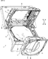
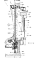
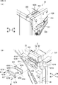
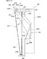
以下、図面を参照しつつ、本発明の実施例2について説明する。図17は、パチンコ遊技機の正面図、図18は、その側断面図、図19は、扉枠の斜視図である。遊技機(パチンコ遊技機)801は、大別して、遊技盤面を構成する遊技盤802と、遊技盤802を支持固定する遊技機用枠803とから構成されている。遊技盤802には、略円形状の遊技領域が形成されている。 Hereinafter, the second embodiment of the present invention will be described with reference to the drawings. 17 is a front view of the pachinko gaming machine, FIG. 18 is a side sectional view thereof, and FIG. 19 is a perspective view of the door frame. The gaming machine (pachinko gaming machine) 801 is roughly classified into a gaming board 802 constituting the game board surface and a game machine frame 803 for supporting and fixing the game board 802. A game area having a substantially circular shape is formed on the game board 802.

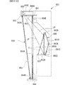
遊技機用枠803は、図18に示すように遊技枠840及び扉枠850を備えている。遊技枠840は、箱状の枠体である。遊技枠840の上方には、前方に突出する上方張出部840Aが形成されている。上方張出部840Aは、遊技枠840と一体的に形成されており、扉枠850よりも前方にまで張り出している。さらに、遊技枠840に設けられた回転軸部材840Bは、上方張出部840Aにまで到達している。扉枠850は、遊技枠840とは別体に形成されており、遊技枠840及び上方張出部840Aに対して、図19に示す回転軸部材840B周りに回動可能とされている。 As shown in FIG. 18, the game machine frame 803 includes a game frame 840 and a door frame 850. The game frame 840 is a box-shaped frame body. Above the game frame 840, an upward overhanging portion 840A projecting forward is formed. The upper overhanging portion 840A is integrally formed with the game frame 840, and overhangs to the front of the door frame 850. Further, the rotary shaft member 840B provided on the game frame 840 reaches the upward overhanging portion 840A. The door frame 850 is formed separately from the game frame 840, and is rotatable around the rotation shaft member 840B shown in FIG. 19 with respect to the game frame 840 and the upward overhanging portion 840A.

扉枠850は、正面視した大きさが遊技枠840と略同じ大きさとされており、遊技枠840に対して開閉可能に取付けられている。また、遊技枠840の左側端部には、上下方向に延在する回転軸部材840Bが設けられている。扉枠850は、回転軸部材840Bを中心として鉛直軸周りに回動可能とされており、回転軸部材840Bを中心として回動することにより、開放状態または閉鎖状態となる。扉枠850が開放状態となることでパチンコ遊技機801の外側から遊技盤802に接触可能となり、扉枠850が閉鎖状態となることで扉枠850が遊技盤802の遊技領域(以下、単に遊技領域という)を覆ってパチンコ遊技機801の外側から遊技盤802に接触不能となる。 The size of the door frame 850 when viewed from the front is substantially the same as that of the game frame 840, and the door frame 850 is attached to the game frame 840 so as to be openable and closable. Further, a rotary shaft member 840B extending in the vertical direction is provided at the left end portion of the game frame 840. The door frame 850 is rotatable around a vertical axis about the rotating shaft member 840B, and is opened or closed by rotating around the rotating shaft member 840B. When the door frame 850 is in the open state, it becomes possible to contact the game board 802 from the outside of the pachinko game machine 801. When the door frame 850 is in the closed state, the door frame 850 becomes the game area of the game board 802 (hereinafter, simply a game). The area) is covered and the game board 802 cannot be contacted from the outside of the pachinko game machine 801.

扉枠850は、図19に示すように、縦長の矩形状をなす枠体851を備えている。枠体851は、長手方向が鉛直方向に沿うように配置されている。枠体851の上辺には、天板852が取付けられている。天板852の先端辺と枠体851の下端辺には、傾斜枠853が取付けられている。 As shown in FIG. 19, the door frame 850 includes a vertically long rectangular frame body 851. The frame body 851 is arranged so that the longitudinal direction is along the vertical direction. A top plate 852 is attached to the upper side of the frame 851. An inclined frame 853 is attached to the tip end side of the top plate 852 and the lower end side of the frame body 851.

また、枠体851には内側透明板854が取付けられ、傾斜枠853には外側透明板855が取付けられている。内側透明板854及び外側透明板855は、いずれも透視性を備えており、パチンコ遊技機801Bの前に位置する遊技者は内側透明板854及び外側透明板855を通して遊技盤802を視認可能とされている。 Further, an inner transparent plate 854 is attached to the frame body 851, and an outer transparent plate 855 is attached to the inclined frame 853. Both the inner transparent plate 854 and the outer transparent plate 855 have transparency, and the player located in front of the pachinko gaming machine 801B can see the game board 802 through the inner transparent plate 854 and the outer transparent plate 855. ing.

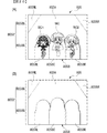
内側透明板854の上方半分位置には、中央開口部854Aが形成されている。中央開口部854Aは、スクリーン805の表面形状より上方部分が一回り大きい矩形状をなしている。中央開口部854Aの形状は、この形状に限らず、例えば円形や楕円形など他の形状であってもよい。 A central opening 854A is formed at the upper half position of the inner transparent plate 854. The central opening 854A has a rectangular shape whose upper portion is slightly larger than the surface shape of the screen 805. The shape of the central opening 854A is not limited to this shape, and may be another shape such as a circular shape or an elliptical shape.

内側透明板854は、遊技盤802の表面に沿って配設され、遊技盤802の表面との離間距離が遊技球の直径よりも長く、遊技球の直径の2倍よりも短くされている。内側透明板854と遊技盤802との離間距離をこの範囲とすることによって、内側透明板854によって、遊技領域からの遊技球の飛び出しを防止している。また、外側透明板855は、内側透明板854の正面側の全面を覆って取付けられている。このため、遊技者が内側透明板854や遊技盤802に触ることが抑制されている。 The inner transparent plate 854 is arranged along the surface of the game board 802, and the distance from the surface of the game board 802 is longer than the diameter of the game ball and shorter than twice the diameter of the game ball. By setting the distance between the inner transparent plate 854 and the game board 802 within this range, the inner transparent plate 854 prevents the game ball from jumping out of the game area. Further, the outer transparent plate 855 is attached so as to cover the entire front surface side of the inner transparent plate 854. Therefore, the player is prevented from touching the inner transparent plate 854 and the game board 802.

内側透明板854は、例えばアクリル製であり、外側透明板855は、例えばガラス製である。内側透明板854がアクリル製であることにより、加工が容易であり、中央開口部854Aを容易に形成することができる。また、外側透明板855がガラス製であることにより、耐久性を高くすることができる。ただし、内側透明板854がガラス製であってもよく、外側透明板855がアクリル製であってもよい。また、内側透明板854及び外側透明板855とも、透視性を備える他の素材で形成されていてもよい。 The inner transparent plate 854 is made of, for example, acrylic, and the outer transparent plate 855 is made of, for example, glass. Since the inner transparent plate 854 is made of acrylic, it is easy to process and the central opening 854A can be easily formed. Further, since the outer transparent plate 855 is made of glass, the durability can be improved. However, the inner transparent plate 854 may be made of glass, and the outer transparent plate 855 may be made of acrylic. Further, both the inner transparent plate 854 and the outer transparent plate 855 may be made of other transparent materials.

また、図18及び図19に示すように、内側透明板854の下方位置における中央部に遊技球排出孔854Bが形成されている。遊技球排出孔854Bは、裏面側の遊技機用枠803に連通しており、内側透明板854と外側透明板855との間に入り込んだ遊技球を遊技機用枠803に向けて排出可能とされている。また、内側透明板854が取付けられた枠体851と外側透明板855が取付けられた傾斜枠853とは、取り外し可能とされている。このため、枠体851と傾斜枠853とを取外すことで、内側透明板854と外側透明板855とは、離間可能とされている。また、遊技球排出孔854Bは、上皿ユニットの裏側に配置されている。この上皿ユニットにより、この化粧板により、遊技球排出孔854Bがパチンコ遊技機801Bの正面外側からは視認できないように、遊技球排出孔854Bが隠されている。また、遊技球排出孔は、上皿ユニットよりも上方に配置され、遊技者が視認可能となる高さ位置に形成されていてもよい。この場合、遊技球排出孔854Bから排出される遊技球が遊技機用枠803に排出されるようにしてもよいし、遊技領域に排出されるようにしてもよい。また、遊技球排出孔854Bに代えて、扉枠850の手前側の例えば図示しない上皿または下皿に排出されるようにしてもよい。また、上皿ユニットが設けられていない遊技機では、遊技球排出孔は、裏側を隠すための化粧板、上皿や下皿、あるいは遊技球を打ち出す際の遊技者に操作されるハンドルなどの付属物やこれらの付属物が設けられるプレートなどに隠される位置に形成されていてもよい。遊技領域には、遊技媒体としての遊技球が、所定の打球発射装置から発射されて打ち込まれる。以下、遊技領域内または遊技領域周辺の主要部材について説明する。 Further, as shown in FIGS. 18 and 19, a game ball discharge hole 854B is formed in a central portion at a position below the inner transparent plate 854. The game ball discharge hole 854B communicates with the game machine frame 803 on the back surface side, and the game ball that has entered between the inner transparent plate 854 and the outer transparent plate 855 can be discharged toward the game machine frame 803. Has been done. Further, the frame body 851 to which the inner transparent plate 854 is attached and the inclined frame 853 to which the outer transparent plate 855 is attached are removable. Therefore, by removing the frame body 851 and the inclined frame 853, the inner transparent plate 854 and the outer transparent plate 855 can be separated from each other. Further, the game ball discharge hole 854B is arranged on the back side of the upper plate unit. With this upper plate unit, the game ball discharge hole 854B is hidden by the decorative plate so that the game ball discharge hole 854B cannot be seen from the front outside of the pachinko game machine 801B. Further, the game ball discharge hole may be arranged above the upper plate unit and may be formed at a height position so that the player can see it. In this case, the game ball discharged from the game ball discharge hole 854B may be discharged to the game machine frame 803, or may be discharged to the game area. Further, instead of the game ball discharge hole 854B, the door frame 850 may be discharged to, for example, an upper plate or a lower plate (not shown) on the front side. Further, in a game machine not provided with an upper plate unit, the game ball discharge hole is a decorative plate for hiding the back side, an upper plate or a lower plate, or a handle operated by a player when launching a game ball. It may be formed in a position hidden by an accessory or a plate on which these accessories are provided. In the game area, a game ball as a game medium is launched from a predetermined ball launching device and is driven into the game area. Hereinafter, the main members in or around the game area will be described.

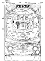
図17に示すように、遊技盤802には、スクリーン805、普通入賞球装置806A、普通可変入賞球装置806B、特別可変入賞球装置807、第1特別図柄表示装置804A、第2特別図柄表示装置804B、センターフレーム804C、第1保留表示器825A、第2保留表示器825B、普通図柄表示器820、通過ゲート841、普図保留表示器825C、及びロゴ役物826が設けられている。また、ロゴ役物826には、図18に示すように、反射ミラー828が設けられている。遊技機用枠803には、スピーカ808(スピーカ808L、808R)、ランプ809、スティックコントローラ831A、プッシュボタン831Bが設けられている。さらに、遊技機用枠803の上方張出部840Aには投影装置としてのプロジェクタ832が設けられており、遊技枠803Aの内側下前方には、サブLED833が設けられている。 As shown in FIG. 17, the game board 802 includes a screen 805, a normal winning ball device 806A, a normal variable winning ball device 806B, a special variable winning ball device 807, a first special symbol display device 804A, and a second special symbol display device. 804B, center frame 804C, first hold display 825A, second hold display 825B, ordinary symbol display 820, passage gate 841, normal figure hold display 825C, and logo accessory 826 are provided. Further, as shown in FIG. 18, the logo accessory 826 is provided with a reflection mirror 828. The frame 803 for the game machine is provided with a speaker 808 (speaker 808L, 808R), a lamp 809, a stick controller 831A, and a push button 831B. Further, a projector 832 as a projection device is provided on the upper overhanging portion 840A of the game machine frame 803, and a sub LED 833 is provided on the inner lower front side of the game frame 803A.

また、遊技盤802における上方には、扉枠850の開閉状態を検出するための扉開放センサ856(図21参照)が取付けられている。扉開放センサ856は、扉枠850の状態が遊技領域を覆う閉鎖状態であるかまたは遊技領域を外部から接触可能な状態にする開放状態であるかを検出している。閉鎖状態と開放状態との検出は、具体的には、前面に遊技領域が形成されている遊技盤802が取付けられた遊技機用枠803に対して扉枠850が開放されているか否かを検出している。扉開放センサ856は、検出した開閉状態を主基板811に送信する。主基板811は、扉開放センサ856から送信された扉枠が開放されている旨の信号を十進したときには、扉開放信号を演出制御基板812に出力する。 Further, a door opening sensor 856 (see FIG. 21) for detecting the open / closed state of the door frame 850 is attached above the game board 802. The door opening sensor 856 detects whether the state of the door frame 850 is a closed state that covers the game area or an open state that makes the game area contactable from the outside. Specifically, the detection of the closed state and the open state determines whether or not the door frame 850 is opened with respect to the game machine frame 803 to which the game board 802 having the game area formed on the front surface is attached. It is being detected. The door opening sensor 856 transmits the detected open / closed state to the main board 811. The main board 811 outputs the door opening signal to the effect control board 812 when the signal transmitted from the door opening sensor 856 to the effect that the door frame is opened is decimal.

遊技盤802に設けられた普通入賞球装置806Aは、常に一定の開放状態に保たれる始動領域としての第1始動入賞口を形成する。普通可変入賞球装置806Bは、図21に示す普通電動役物用となるソレノイド881によって、通常開放状態と拡大開放状態とに変化する電動チューリップ型役物を備え、始動領域としての第2始動入賞口を形成する。尚、電動チューリップ型役物は、普図ゲーム(後述)における可変表示結果(最終結果)が「普図当り」になった場合に拡大開放状態に制御される。特別可変入賞球装置807は、図21に示す大入賞口扉用となるソレノイド882によって開閉駆動される大入賞口扉を備え、大入賞口扉によって開放状態と閉鎖状態とに変化する特定領域としての大入賞口を形成する。尚、大入賞口は、第1特図ゲーム(後述)または第2特図ゲーム(後述)における可変表示結果(最終結果)が「大当り」になった場合等に開放状態に制御される。 The ordinary winning ball device 806A provided on the game board 802 forms a first starting winning opening as a starting region that is always kept in a constant open state. The ordinary variable winning ball device 806B includes an electric tulip-shaped accessory that changes between a normally open state and an expanded open state by a solenoid 881 for an ordinary electric accessory shown in FIG. 21, and has a second starting prize as a starting region. Form the mouth. The electric tulip-type accessory is controlled to be in the enlarged open state when the variable display result (final result) in the normal map game (described later) becomes "normal map hit". The special variable winning ball device 807 includes a large winning opening door that is opened and closed by a solenoid 882 for the large winning opening door shown in FIG. 21, as a specific area that changes between an open state and a closed state depending on the large winning opening door. Form a big winning opening. The big prize opening is controlled to be in an open state when the variable display result (final result) in the first special figure game (described later) or the second special figure game (described later) becomes a "big hit".

第1特別図柄表示装置804Aは、普通入賞球装置806Aへの入賞の後に(遊技球が第1始動入賞口を通過したことによる第1始動条件が成立した後に)、後述する第1開始条件が成立したことに基づいて特別図柄の可変表示を行う。第2特別図柄表示装置804Bは、普通可変入賞球装置806Bへの入賞の後に(遊技球が第2始動入賞口を通過したことによる第2始動条件が成立した後に)、後述する第2開始条件が成立したことに基づいて特別図柄の可変表示を行う。 The first special symbol display device 804A has a first start condition, which will be described later, after winning a prize in the ordinary winning ball device 806A (after the first start condition is satisfied by the game ball passing through the first start winning opening). Variable display of the special symbol is performed based on the establishment. The second special symbol display device 804B has a second start condition, which will be described later, after winning a prize in the ordinary variable winning ball device 806B (after the second start condition is satisfied by the game ball passing through the second start winning opening). The special symbol is variably displayed based on the establishment of.

以下、第1特別図柄表示装置804Aにおいて可変表示される特別図柄を第1特図とも称し、第1特図の可変表示を「第1特図ゲーム」とも称する。第2特別図柄表示装置804Bにおいて可変表示される特別図柄を第2特図とも称し、第2特図の可変表示を「第2特図ゲーム」とも称する。また、第1特図ゲームと第2特図ゲームの両方を「特図ゲーム」と総称し、第1始動条件と第2始動条件の両方を「特図始動条件」と総称し、第1開始条件と第2開始条件の両方を「特図開始条件」と総称する場合がある。 Hereinafter, the special symbol variably displayed on the first special symbol display device 804A is also referred to as a first special symbol, and the variable display of the first special symbol is also referred to as a “first special symbol game”. The special symbol that is variably displayed on the second special symbol display device 804B is also referred to as a second special symbol, and the variable display of the second special symbol is also referred to as a "second special symbol game". In addition, both the first special figure game and the second special figure game are collectively referred to as "special figure game", and both the first start condition and the second start condition are collectively referred to as "special figure start condition", and the first start Both the condition and the second start condition may be collectively referred to as "special figure start condition".

特図ゲームにおける可変表示結果が「大当り」になった後(例えば、大当り図柄として予め定められた特別図柄が可変表示結果として導出表示(停止表示)された後)には、大当り遊技状態(遊技者にとって有利な有利状態の一例)に制御される。大当り遊技状態とは、特別可変入賞球装置807の大入賞口扉が、所定の上限時間(例えば29秒間や0.1秒間)が経過するまでの期間あるいは所定個数(例えば9個)の入賞球が発生するまでの期間、大入賞口を開放状態に制御する遊技状態である。 After the variable display result in the special figure game becomes "big hit" (for example, after the special symbol predetermined as the big hit symbol is derived and displayed (stop display) as the variable display result), the big hit game state (game). It is controlled to an example of an advantageous state that is advantageous to the person). The jackpot game state is a period until a predetermined upper limit time (for example, 29 seconds or 0.1 seconds) elapses or a predetermined number (for example, 9) of winning balls at the big winning opening door of the special variable winning ball device 807. It is a gaming state in which the large winning opening is controlled to be open until the occurrence of.

普通入賞球装置806Aへの入賞があったにもかかわらず(第1始動条件が成立したにもかかわらず)、未だ第1特図ゲームを開始するための開始条件(第1開始条件とも称する)が成立していないときには、当該入賞に対応する可変表示は、保留記憶として記憶される。具体的には、当該入賞に基づく可変表示(第1特図ゲーム)を実行するための情報が、所定数(例えば4)を上限に入賞順がわかるような態様で保留される(第1特図保留記憶として記憶される。詳細は後述する)。普通可変入賞球装置806Bへの入賞があったにもかかわらず(第2始動条件が成立したにもかかわらず)、未だ第2特図ゲームを開始するための開始条件(第2開始条件とも称する)が成立していないときには、当該入賞に対応する可変表示は、保留記憶として記憶される。具体的には、当該入賞に基づく可変表示(第2特図ゲーム)を実行するための情報が、所定数(例えば4)を上限に入賞順がわかるような態様で保留される(第2特図保留記憶として記憶される。詳細は後述する)。また、例えば、第1特図保留記憶や第2特図保留記憶とは別に第1特図保留記憶と第2特図保留記憶とを合せた全体(下記の特図保留記憶)における入賞順がわかるような情報を記憶してもよい。尚、第1始動条件の成立時に直ちに第1開始条件が成立したときにも、一瞬ではあるが(記憶後に直ちに消化されるが)、第1特図保留記憶が記憶されるようにしてもよい。また、第2始動条件の成立時に直ちに第2開始条件が成立したときにも、一瞬ではあるが、第2特図保留記憶が記憶されるようにしてもよい。尚、第1特図保留記憶と第2特図保留記憶の両方を「特図保留記憶」と総称する場合がある。 Despite having won a prize in the normal winning ball device 806A (despite the fact that the first starting condition is satisfied), the starting condition for starting the first special figure game (also referred to as the first starting condition). When is not satisfied, the variable display corresponding to the winning is stored as a hold memory. Specifically, information for executing the variable display (first special figure game) based on the winning is held in such a manner that the winning order can be understood up to a predetermined number (for example, 4) (first special figure). The figure is stored as a hold memory. Details will be described later). Even though there was a prize in the normal variable winning ball device 806B (despite the fact that the second starting condition was satisfied), the starting condition for starting the second special figure game (also called the second starting condition). ) Is not established, the variable display corresponding to the winning is stored as a hold memory. Specifically, the information for executing the variable display (second special figure game) based on the winning is held in such a manner that the winning order can be understood up to a predetermined number (for example, 4) (second special). The figure is stored as a hold memory. Details will be described later). Further, for example, the winning order in the whole (the following special figure holding memory) in which the first special figure holding memory and the second special figure holding memory are combined separately from the first special figure holding memory and the second special figure holding memory is You may store information that you can understand. Even when the first start condition is satisfied immediately after the first start condition is satisfied, the first special figure reserved memory may be stored for a moment (although it is immediately digested after the memory). .. Further, even when the second start condition is satisfied immediately when the second start condition is satisfied, the second special figure hold memory may be stored for a moment. In addition, both the first special figure holding memory and the second special figure holding memory may be collectively referred to as "special figure holding memory".

特図開始条件は、例えば、特図ゲームの保留数(特図保留記憶数とも称する)が0でない場合であって、特図ゲームが実行されていない状態であり、且つ、大当り遊技状態に制御されていない状態であるときに成立する。特図開始条件が成立したときは(特図ゲームが開始される毎に)、特図保留記憶は消化され(特図保留記憶が減少し)、特図ゲームが開始される。換言すれば、特図保留記憶は、特図ゲームが開始される毎に減少する。より詳細には、第1特図ゲームの保留数(第1特図保留記憶数)は、第1特図ゲームが開始される毎に(第1開始条件が成立する毎に)減少し、第2特図ゲームの保留数(第2特図保留記憶数)は、第2特図ゲームが開始される毎に(第2開始条件が成立する毎に)減少する。 The special figure start condition is, for example, a case where the number of reserved special figure games (also referred to as the number of stored special figures) is not 0, the special figure game is not executed, and the game is controlled to a big hit game state. It is established when it is not done. When the special figure start condition is satisfied (every time the special figure game is started), the special figure hold memory is digested (the special figure hold memory decreases), and the special figure game is started. In other words, the special figure hold memory decreases each time the special figure game is started. More specifically, the number of hold of the first special figure game (the number of hold memory of the first special figure) decreases every time the first special figure game is started (every time the first start condition is satisfied), and the first The number of 2 special figure games on hold (the number of 2nd special figure hold storages) decreases each time the 2nd special figure game is started (every time the 2nd start condition is satisfied).

本実施例では、特図保留記憶は、第1特図保留記憶であるか第2特図保留記憶であるかにかかわらず、入賞順に消化する。従って、例えば、第1特図保留記憶、第1特図保留記憶、第2特図保留記憶、第1特図保留記憶の順に記憶されている場合には、第1開始条件、第1開始条件、第2開始条件、第1開始条件の順に成立する。つまり、上述したように、特図開始条件は、特図保留記憶数が0でない場合であって、特図ゲームが実行されていない状態であり、且つ、大当り遊技状態に制御されていない状態であるときに成立するが、より詳細には、最も先に記憶された特図保留記憶が第1特図保留記憶である場合には第1開始条件が成立し、最も先に記憶された特図保留記憶が第2特図保留記憶である場合には第2開始条件が成立する。 In this embodiment, the special figure holding memory is digested in the order of winning regardless of whether it is the first special figure holding memory or the second special figure holding memory. Therefore, for example, when the first special figure holding memory, the first special figure holding storage, the second special figure holding storage, and the first special figure holding storage are stored in this order, the first start condition and the first start condition are stored. , The second start condition, and the first start condition are satisfied in this order. That is, as described above, the special figure start condition is a state where the special figure hold memory number is not 0, the special figure game is not executed, and the special figure game state is not controlled. It is established at a certain time, but more specifically, when the special figure holding memory stored first is the first special figure holding storage, the first start condition is satisfied and the special figure stored first. When the hold memory is the second special figure hold memory, the second start condition is satisfied.

センターフレーム804Cは、遊技盤802の中央に設けられており、センターフレーム804Cの中央部分にスクリーン取付孔802Aが形成されている。センターフレーム804Cの上面804Dには、右打誘導路804Eが形成されている。右打ちされた遊技球は、図示しない釘等によって、普通可変入賞球装置806B及び開放状態の特別可変入賞球装置807に向けて誘導される。右打ちされた遊技球は、拡大開放状態の普通可変入賞球装置806B及び開放状態の特別可変入賞球装置807には入賞しやすいが、普通入賞球装置806Aには入賞しにくくなっている。尚、「右打ち」とは、一般に、遊技球が遊技盤802の右側に形成されたルートを通って遊技領域の下方に流下するように遊技球を発射することをいう。 The center frame 804C is provided in the center of the game board 802, and a screen mounting hole 802A is formed in the central portion of the center frame 804C. A right-handed taxiway 804E is formed on the upper surface 804D of the center frame 804C. The right-handed game ball is guided toward the normal variable winning ball device 806B and the special variable winning ball device 807 in the open state by a nail or the like (not shown). The right-handed game ball is easy to win in the ordinary variable winning ball device 806B in the expanded open state and the special variable winning ball device 807 in the open state, but is difficult to win in the ordinary winning ball device 806A. In addition, "right-handed" generally means launching a game ball so that the game ball flows down the game area through a route formed on the right side of the game board 802.

第1保留表示器825Aは、第1特図ゲームの保留数(第1特図保留記憶数)を特定可能に表示する。第2保留表示器825Bは、第2特図ゲームの保留数(第2特図保留記憶数)を特定可能に表示する。普通図柄表示器820は、遊技球が通過ゲート841を通過した後に(遊技球が通過ゲート841を通過したことによる普図始動条件が成立した後に)、後述する普図ゲームの開始条件が成立したことに基づいて普通図柄の可変表示を行う。尚、普通図柄の可変表示を「普図ゲーム」とも称する。 The first hold indicator 825A displays the number of holds of the first special figure game (the number of holds of the first special figure) in a identifiable manner. The second hold indicator 825B displays the number of holds of the second special figure game (the number of holds of the second special figure) in a identifiable manner. In the ordinary symbol display 820, after the game ball has passed through the passing gate 841 (after the normal drawing start condition is satisfied due to the game ball passing through the passing gate 841), the starting condition of the normal drawing game described later is satisfied. Based on this, the normal symbol is displayed in a variable manner. In addition, the variable display of a normal symbol is also referred to as a "general figure game".

遊技球が通過ゲート841を通過したにもかかわらず(普図始動条件が成立したにもかかわらず)、未だ普図ゲームの開始条件(普図開始条件とも称する)が成立していないときには、当該通過に基づく可変表示(普図ゲーム)は所定数(例えば4)を上限に保留される(普図保留記憶として記憶される)。 When the game ball has passed through the passage gate 841 (despite the fact that the normal figure start condition is satisfied), but the start condition of the normal figure game (also referred to as the normal figure start condition) is not yet satisfied, the relevant case is concerned. The variable display based on the passage (normal figure game) is held up to a predetermined number (for example, 4) (stored as a normal figure hold memory).

普図ゲームの開始条件(普図開始条件)は、例えば、普通保留記憶数が0でない場合であって、普通図柄の可変表示(普図ゲーム)が実行されていない状態であり、且つ、大当り遊技状態に制御されていない状態であるときに成立する条件であってもよい。尚、普図始動条件の成立時に直ちに普図開始条件が成立したときにも、一瞬ではあるが、普図保留記憶が記憶されるようにしてもよい。 The start condition of the normal figure game (normal figure start condition) is, for example, a case where the normal hold storage number is not 0, the variable display of the normal symbol (normal figure game) is not executed, and a big hit. It may be a condition that is satisfied when the game state is not controlled. It should be noted that even when the normal figure start condition is satisfied immediately when the normal figure start condition is satisfied, the normal figure hold memory may be stored for a moment.

普図保留表示器825Cは、普図ゲームの保留数(普図保留記憶数)を特定可能に表示する。尚、普図ゲームの保留数(普図保留記憶数とも称する)は、普図ゲームが開始される毎に(普図開始条件が成立する毎に)減少する。 The normal figure hold display 825C displays the number of hold of the normal figure game (the number of hold memory of the normal figure) in a identifiable manner. It should be noted that the number of reserved fuzu games (also referred to as the number of reserved fuzu) decreases every time the fuzu game is started (every time the conditions for starting the fuzu are satisfied).

プロジェクタ832は、上方張出部840Aの前端位置に対して取付けられている。上方張出部840Aの下面には、プロジェクタ832から投影される投影光LPが通過可能とされた開口部840Cが形成されている。プロジェクタ832から投影される投影光LPは、開口部840Cを通過してスクリーン805に投影される。 The projector 832 is attached to the front end position of the upward overhanging portion 840A. An opening 840C is formed on the lower surface of the upper overhanging portion 840A so that the projected light LP projected from the projector 832 can pass through. The projected light LP projected from the projector 832 passes through the opening 840C and is projected onto the screen 805.

スクリーン805は、遊技盤802の中央に形成されたスクリーン取付孔802Aに設けられており、遊技盤802の奥方に配置されている。スクリーン805は、横長の長方形状をなし、飾り図柄(演出図柄とも称する)の可変表示や各種の演出表示を行う。また、スクリーン805は、表示領域として平面表示領域805A及び立体表示領域805Bを備えている。立体表示領域805Bは、中央立体表示領域805BC、右立体表示領域805BR、及び左立体表示領域805BLを備えている。これらの中央立体表示領域805BC、右立体表示領域805BR、及び左立体表示領域805BLは、いずれもフィギア状をなしている。スクリーン805は、平面板にフィギア状の立体物が貼り付けられて形成されており、立体物が貼り付けられていない位置が平面表示領域となり、立体物が貼り付けられた位置が立体表示領域805Bとなる。 The screen 805 is provided in the screen mounting hole 802A formed in the center of the game board 802, and is arranged in the back of the game board 802. The screen 805 has a horizontally long rectangular shape, and performs variable display of decorative symbols (also referred to as effect symbols) and various effect displays. Further, the screen 805 includes a flat display area 805A and a stereoscopic display area 805B as display areas. The stereoscopic display area 805B includes a central stereoscopic display area 805BC, a right stereoscopic display area 805BR, and a left stereoscopic display area 805BL. The central stereoscopic display area 805BC, the right stereoscopic display area 805BR, and the left stereoscopic display area 805BL all have a figure shape. The screen 805 is formed by attaching a figure-like three-dimensional object to a flat plate, the position where the three-dimensional object is not attached is the flat display area, and the position where the three-dimensional object is attached is the three-dimensional display area 805B. It becomes.

平面表示領域805Aには、後に説明する特定画像や背景画像などが主に表示される。また、中央立体表示領域805BC、右立体表示領域805BR、及び左立体表示領域805BLには、それぞれの立体表示領域に対応するキャラクタが主に表示される。図17に示す例では、中央立体表示領域805BCにメインキャラクタ画像MCが表示され、左立体表示領域805BLに第1サブキャラクタ画像SC1が表示され、右立体表示領域805BRに第2サブキャラクタ画像SC2が表示される。特図ゲームが開始される際には、原則的に、立体表示領域805BC,805BL,805BRにキャラクタ画像MC,SC1,SC2を表示した状態として演出を実行する。 A specific image, a background image, or the like, which will be described later, is mainly displayed in the flat display area 805A. In addition, characters corresponding to the respective stereoscopic display areas are mainly displayed in the central stereoscopic display area 805BC, the right stereoscopic display area 805BR, and the left stereoscopic display area 805BL. In the example shown in FIG. 17, the main character image MC is displayed in the central stereoscopic display area 805BC, the first sub-character image SC1 is displayed in the left stereoscopic display area 805BL, and the second sub-character image SC2 is displayed in the right stereoscopic display area 805BR. Is displayed. When the special figure game is started, in principle, the effect is executed with the character images MC, SC1 and SC2 displayed in the stereoscopic display areas 805BC, 805BL and 805BR.

尚、中央立体表示領域805BC、左立体表示領域805BL、右立体表示領域805BRには、それぞれ対応するメインキャラクタ画像MC、第1サブキャラクタ画像SC1、及び第2サブキャラクタ画像SCキャラクタを表示しているが、他の画像を表示するようにしてもよい。例えば、表示されるキャラクタが入れ替わり、中央立体表示領域805BCに第1サブキャラクタ画像SC1または第2サブキャラクタ画像SC2が表示されるようにしてもよい。また、立体表示領域805Bにキャラクタ以外の画像、例えば背景画像が表示されるようにしてもよいし、平面表示領域805Aにキャラクタ画像が表示されるようにしてもよい。 The corresponding main character image MC, first sub-character image SC1, and second sub-character image SC character are displayed in the central stereoscopic display area 805BC, the left stereoscopic display area 805BL, and the right stereoscopic display area 805BR, respectively. However, other images may be displayed. For example, the displayed characters may be interchanged so that the first sub-character image SC1 or the second sub-character image SC2 is displayed in the central stereoscopic display area 805BC. Further, an image other than the character, for example, a background image may be displayed in the stereoscopic display area 805B, or the character image may be displayed in the flat display area 805A.

スクリーン805上には、図20(A)(B)に示すように、プロジェクタ832から投影される映像(画像)が表示される投影領域805Xが形成される。プロジェクタ832から投影された映像は、反射ミラー828で反射されてスクリーン805上の投影領域805Xに表示される。スクリーン805上の投影領域805Xに表示される画像は、プロジェクタ832が投影する映像によって形成されることとなる。投影領域805Xは、スクリーン805の平面表示領域805A及び立体表示領域805Bの双方に形成され、プロジェクタ832からの映像によるいわゆるプロジェクションマッピングによって演出が実行される。投影領域805Xには、平面表示領域805Aの一部及び立体表示領域805Bの全体が含まれている。 As shown in FIGS. 20A and 20B, a projection area 805X on which an image (image) projected from the projector 832 is displayed is formed on the screen 805. The image projected from the projector 832 is reflected by the reflection mirror 828 and displayed in the projection area 805X on the screen 805. The image displayed in the projection area 805X on the screen 805 is formed by the image projected by the projector 832. The projection area 805X is formed in both the flat display area 805A and the stereoscopic display area 805B of the screen 805, and the effect is executed by so-called projection mapping by the image from the projector 832. The projection area 805X includes a part of the flat display area 805A and the entire stereoscopic display area 805B.

スクリーン805における立体表示領域805Bに映像が投影されることにより、図20(A)に示すように、立体表示領域805Bには、立体形状に合せた立体画像に見える画像は表示される。また、立体表示領域805Bに映像が投影されていない状態では、図20(B)に示すように、立体表示領域805Bにおける立体形状は視認困難な状態であり、遊技者が立体表示領域805Bの立体形状を認識することは難しい状態となっている。 By projecting an image onto the stereoscopic display area 805B on the screen 805, as shown in FIG. 20A, an image that looks like a stereoscopic image that matches the stereoscopic shape is displayed in the stereoscopic display area 805B. Further, when the image is not projected on the stereoscopic display area 805B, as shown in FIG. 20B, the stereoscopic shape in the stereoscopic display area 805B is difficult to see, and the player can see the stereoscopic shape in the stereoscopic display area 805B. It is difficult to recognize the shape.

立体表示領域805Bが設けられていることにより、プロジェクタ832とスクリーン805との間の距離は、一様とではない。具体的には、スクリーン805の表面にプロジェクタ832を配置した場合には、立体表示領域805Bの方が、平面表示領域805Aよりも近くなる。このため、プロジェクタ832から投影される映像の焦点は、プロジェクタ832から投影される映像における所定軸、例えば光軸上の立体表示領域805Bの表面に相当する位置(以下「立体表面相当位置」という)と平面表示領域805Aに相当する位置(以下「平面表面相当位置」という)の間の位置、例えばその中間位置に設定されている。立体表面相当位置と平面表面相当位置とに間に焦点を設定することにより、スクリーン805の全面にわたって映像の歪みを小さくすることができる。また、立体表面相当位置と平面表面相当位置とに間に焦点を設定する代わりに焦点を調節可能としてもよいし、立体表面相当位置と平面表面相当位置とに間に焦点を設定し、さらに焦点を調節可能としてもよい。 Due to the provision of the stereoscopic display area 805B, the distance between the projector 832 and the screen 805 is not uniform. Specifically, when the projector 832 is arranged on the surface of the screen 805, the stereoscopic display area 805B is closer than the flat display area 805A. Therefore, the focus of the image projected from the projector 832 is a position corresponding to the surface of the stereoscopic display area 805B on a predetermined axis, for example, the optical axis in the image projected from the projector 832 (hereinafter referred to as "three-dimensional surface equivalent position"). It is set at a position between the above and a position corresponding to the plane display area 805A (hereinafter referred to as "a plane surface corresponding position"), for example, an intermediate position thereof. By setting the focus between the position corresponding to the three-dimensional surface and the position corresponding to the plane surface, the distortion of the image can be reduced over the entire surface of the screen 805. Further, instead of setting the focus between the three-dimensional surface equivalent position and the plane surface equivalent position, the focus may be adjustable, or the focus is set between the three-dimensional surface equivalent position and the plane surface equivalent position, and further the focus is set. May be adjustable.

また、プロジェクタ832は、スクリーン805の上方に配置されており、プロジェクタ832から投影される映像は、スクリーン805の前上方からスクリーン805に投影される。こうして、プロジェクタ832は、投影光LPの光軸とスクリーン805の表示面(平面表示領域805A)とが直交せず、スクリーン805の表示面に対して斜め方向を向いた投影方向からスクリーン805に画像を投影する。プロジェクタ832は、斜め方向を向いた投影方向から画像を投影することから、スクリーン805に表示される画像は台形状となる。また、スクリーン805は長方形状であり、スクリーン805とプロジェクタ832から投影される画像の領域とは一致せず、スクリーン805は、スクリーン805に表示される画像よりも広くなっている。 Further, the projector 832 is arranged above the screen 805, and the image projected from the projector 832 is projected onto the screen 805 from the front upper side of the screen 805. In this way, in the projector 832, the optical axis of the projected light LP and the display surface (planar display area 805A) of the screen 805 are not orthogonal to each other, and the image is projected onto the screen 805 from a projection direction oblique to the display surface of the screen 805. To project. Since the projector 832 projects an image from a projection direction facing an oblique direction, the image displayed on the screen 805 has a trapezoidal shape. Further, the screen 805 has a rectangular shape and does not match the area of the image projected from the screen 805 and the projector 832, and the screen 805 is wider than the image displayed on the screen 805.

このため、図17に示すように、スクリーン805における平面表示領域805Aの範囲内における投影領域805Xのうち、平面表示領域805Aの下方の部分に形成される領域は、幅が広い幅広部805XWとされ、平面表示領域805Aの上方の部分に形成される領域は、幅広部805XWよりも幅が狭い幅狭部805XNとされる。投影領域805Xは台形状を成しており、スクリーン805は長方形状をなすことから、幅狭部805XNの左右位置は、プロジェクタ832から投影された映像が届かない非投影領域805NL,805NRとなる。 Therefore, as shown in FIG. 17, of the projection area 805X within the range of the plane display area 805A on the screen 805, the area formed in the lower portion of the plane display area 805A is a wide wide portion 805XW. The region formed in the upper portion of the plane display region 805A is a narrow portion 805XN which is narrower than the wide portion 805XW. Since the projection area 805X has a trapezoidal shape and the screen 805 has a rectangular shape, the left and right positions of the narrow portion 805XN are non-projection areas 805NL and 805NR in which the image projected from the projector 832 does not reach.

非投影領域805NL,805NRは、幅狭部805XNの外の領域に相当し、投影領域805Xにおける幅広部805XWと幅狭部805XNとの幅の差分を有する領域である。言い換えると、幅広部805XWの幅と、幅狭部805XNのうちの最も幅が狭い部分の幅との差が、非投影領域805NL,805NRの最大幅となる。遊技枠803Aの内側下前方に設けられたサブLED833は、この非投影領域805NL,805NRに照射光LLを照射して非投影領域805NL,805NRを発光させ、スクリーン805の全面において、映像(光)が表示されない範囲をなくしている。尚、平面表示領域805Aの多くの部分が幅狭部805XNに含まれ、わずかな部分が幅広部805XWに含まれている。また、立体表示領域805Bは、全て幅広部805XWに含まれている。ただし、平面表示領域805A及び立体表示領域805Bが幅広部805XW及び幅狭部805XNのいずれに含まれるかについては他の態様としてもよい。例えば、幅広部805XWまたは幅狭部805XNに平面表示領域805Aの全体または立体表示領域805Bの全体が含まれていてもよいし、それらの各一部分が含まれていてもよい。 The non-projected regions 805NL and 805NR correspond to regions outside the narrow portion 805XN, and are regions having a difference in width between the wide portion 805XW and the narrow portion 805XN in the projected region 805X. In other words, the difference between the width of the wide portion 805XW and the width of the narrowest portion of the narrow portion 805XN is the maximum width of the non-projected regions 805NL and 805NR. The sub LED 833 provided on the inner lower front side of the game frame 803A irradiates the non-projection area 805NL, 805NR with the irradiation light LL to emit the non-projection area 805NL, 805NR, and the image (light) is displayed on the entire surface of the screen 805. The range where is not displayed is eliminated. Most of the flat display area 805A is included in the narrow portion 805XN, and a small portion is included in the wide portion 805XW. Further, the stereoscopic display area 805B is all included in the wide portion 805XW. However, another aspect may be used as to whether the flat display area 805A and the stereoscopic display area 805B are included in the wide portion 805XW or the narrow portion 805XN. For example, the wide portion 805XW or the narrow portion 805XN may include the entire planar display region 805A or the entire stereoscopic display region 805B, or may include each portion thereof.

また、スクリーン805における周囲の部材、具体的には、センターフレーム804C、釘、風車などが難反射材で形成されている。難反射材としては、投影光LPを反射しにくい色である黒などの黒色系の色とされたものや、投影光LPを反射しにくい材質、例えばカーボンブラック、酸化クロム、表面が荒い材質のものを用いてもよい。 Further, the peripheral members of the screen 805, specifically, the center frame 804C, nails, wind turbines, and the like are made of a non-reflective material. As the non-reflective material, a black color such as black, which is a color that does not easily reflect the projected light LP, or a material that does not easily reflect the projected light LP, such as carbon black, chromium oxide, or a material having a rough surface, is used. You may use the thing.

また、スクリーン805には、図17に示すように、飾り図柄表示エリア805L,805C,805R、保留表示エリア805H1,805H2、保留数表示エリア805F、及び今回表示エリア805Kが配置されている。また、飾り図柄表示エリア805L,805C,805Rでは、特図ゲームに対応して、飾り図柄の可変表示が行われる。その後、特図ゲームにおける可変表示結果として確定特別図柄が導出表示されることに対応して、飾り図柄表示エリア805L,805C,805Rにおいて可変表示結果となる確定飾り図柄(最終停止図柄)が導出表示される。尚、飾り図柄表示エリア805L,805C,805Rの夫々にて可変表示が行われる飾り図柄を夫々、左図柄、中図柄、右図柄とも称する。尚、識別情報の可変表示を可変表示ゲームと総称する場合があるが、上述した特図ゲーム、普図ゲームとともに、飾り図柄の可変表示も可変表示ゲームに含まれる。 Further, as shown in FIG. 17, the screen 805 is arranged with decorative pattern display areas 805L, 805C, 805R, hold display areas 805H1, 805H2, hold number display area 805F, and this time display area 805K. Further, in the decorative symbol display areas 805L, 805C, and 805R, the decorative symbol is variably displayed in accordance with the special symbol game. After that, in response to the definite special symbol being derived and displayed as the variable display result in the special symbol game, the definite decorative symbol (final stop symbol) that is the variable display result is derived and displayed in the decorative symbol display areas 805L, 805C, and 805R. Will be done. The decorative symbols that are variably displayed in the decorative symbol display areas 805L, 805C, and 805R are also referred to as left symbols, middle symbols, and right symbols, respectively. The variable display of the identification information may be collectively referred to as a variable display game, but the variable display game includes the variable display of the decorative pattern as well as the special figure game and the normal figure game described above.

特図ゲームにおける可変表示結果が「大当り」になるときには、飾り図柄表示エリア805L,805C,805Rにおいて、予め定められた大当り組合せとなる確定飾り図柄が導出表示される。また、特図ゲームにおける可変表示結果が「大当り」とならないときには、飾り図柄表示エリア805L,805C,805Rにおいて、予め定められた大当り組合せとは異なる確定飾り図柄が導出表示される。予め定められた大当り組合せの一例は、左図柄、中図柄、右図柄が同一図柄となる組合せ(例えば、(「7」「7」「7」)等)である。 When the variable display result in the special figure game is "big hit", a fixed decorative symbol that is a predetermined jackpot combination is derived and displayed in the decorative symbol display areas 805L, 805C, and 805R. Further, when the variable display result in the special figure game does not become a "big hit", a definite decorative symbol different from the predetermined jackpot combination is derived and displayed in the decorative symbol display areas 805L, 805C, and 805R. An example of a predetermined jackpot combination is a combination in which the left symbol, the middle symbol, and the right symbol have the same symbol (for example, (“7”, “7”, “7”), etc.).

保留表示エリア805H1,805H2では、特図ゲームに対応する飾り図柄の可変表示の保留数が特定可能に表示される。例えば、保留表示エリア805H1,805H2では、第1特図ゲームに対応する飾り図柄及び第2特図ゲームに対応する飾り図柄ごとの入賞順(消化順)がわかるような態様で、飾り図柄の可変表示の保留数に応じた数の保留表示が表示される。具体的には、第1保留表示エリア805H1には、第1特図ゲームに対応する飾り図柄の保留表示が入賞順に従って並べられて表示され、第2保留表示エリア805H2には、第2特図ゲームに対応する飾り図柄の保留表示が入賞順に従って並べられて表示される。また、保留表示エリア805H1,805H2では、当該特図ゲームに対応する飾り図柄の可変表示が開始される毎に、開始される可変表示に対応する保留表示が消去(消化)されるとともに、消去される保留表示の他に他の保留表示があるときには当該他の保留表示の表示位置が消去される保留表示の側(今回表示エリア805Kの側)に移動(シフト)される。 In the hold display areas 805H1 and 805H2, the number of holds for variable display of decorative symbols corresponding to the special figure game is identifiablely displayed. For example, in the hold display areas 805H1 and 805H2, the decorative symbols are variable in such a manner that the winning order (digestion order) for each decorative symbol corresponding to the first special figure game and the decorative symbol corresponding to the second special figure game can be known. The number of pending displays is displayed according to the number of pending displays. Specifically, in the first hold display area 805H1, the hold displays of the decorative symbols corresponding to the first special figure game are arranged and displayed in the order of winning, and in the second hold display area 805H2, the second special figure is displayed. Hold displays of decorative symbols corresponding to the game are displayed side by side in the order of winning. Further, in the hold display areas 805H1 and 805H2, each time the variable display of the decorative symbol corresponding to the special figure game is started, the hold display corresponding to the started variable display is erased (digested) and erased. When there is another hold display in addition to the hold display, the display position of the other hold display is moved (shifted) to the hold display side (the side of the display area 805K this time) in which the display position is deleted.

保留数表示エリア805Fでは、保留表示エリア805H1,805H2と同様、特図ゲームに対応する飾り図柄の可変表示の保留数が特定可能に表示される。その表示態様は、算用数字で表示される態様である。今回表示エリア805Kでは、今回表示(消化時表示、アクティブ表示などとも称される場合がある)が表示される。今回表示とは、消化された保留表示に対応する飾り図柄の可変表示に応じて表示されるもの(保留表示が消化されるときに消化される保留表示に代えて表示されるもの)である。尚、保留表示や今回表示は、単純な図形、例えば円形で示されている。 In the hold number display area 805F, as in the hold display areas 805H1 and 805H2, the hold number of the variable display of the decorative symbol corresponding to the special figure game is identifiablely displayed. The display mode is a mode displayed by arithmetic numbers. In the current display area 805K, the current display (sometimes referred to as digestion display, active display, etc.) is displayed. The display this time is displayed according to the variable display of the decorative symbol corresponding to the digested hold display (displayed in place of the hold display that is digested when the hold display is digested). The hold display and the current display are shown by simple figures such as circles.

これらの飾り図柄表示エリア805L,805C,805R、保留表示エリア805H1,805H2、保留数表示エリア805F、及び今回表示エリア805Kは、いずれも平面表示領域805Aに表示されている。このため、飾り図柄表示エリア805L,805C,805Rに表示される飾り図柄、保留表示エリア805H1,805H2に表示される保留表示、保留数表示エリア805Fに表示される保留数表示、及び今回表示エリア805Kに表示される今回表示は、いずれも平面状の平面表示領域805Aに表示される。 These decorative symbol display areas 805L, 805C, 805R, hold display areas 805H1, 805H2, hold number display area 805F, and this time display area 805K are all displayed in the flat display area 805A. Therefore, the decorative symbols displayed in the decorative symbol display areas 805L, 805C, and 805R, the hold display displayed in the hold display areas 805H1 and 805H2, the hold number display displayed in the hold number display area 805F, and the current display area 805K. All of the current displays displayed in are displayed in the flat flat display area 805A.

遊技機801では、種々の演出が実行可能である。例えば、遊技機801では、確定飾り図柄が導出表示される迄の間において、例えば、予め定められた大当り組合せと一部が一致している状態(リーチ状態)で行われるリーチ演出が実行される。大当り組合せと一部が一致している状態とは、例えば、同一の左図柄と右図柄とが導出表示されている状態であって中図柄が未だ可変表示している状態である。また、遊技機801では、保留表示の表示態様による演出や今回表示の表示態様による演出が実行可能である。また、遊技機801では、スピーカ808やランプ809を用いた演出も実行可能である。遊技機801では、これらの演出を実行することによって、例えば大当り期待度(信頼度)を遊技者に報知または示唆している。 In the game machine 801, various effects can be executed. For example, in the game machine 801, a reach effect is executed in a state (reach state) in which, for example, a part matches a predetermined jackpot combination until the final decoration symbol is derived and displayed. .. The state in which the jackpot combination and a part of the same match is, for example, a state in which the same left symbol and right symbol are derived and displayed, and the middle symbol is still variably displayed. Further, in the game machine 801, it is possible to execute an effect based on the display mode of the hold display and an effect based on the display mode of the current display. Further, in the game machine 801, it is possible to perform an effect using the speaker 808 and the lamp 809. In the game machine 801, for example, the jackpot expectation degree (reliability) is notified or suggested to the player by executing these effects.

ある演出Aの大当り期待度(信頼度)は、例えば、(大当りとなるときに演出Aが実行される確率)×(大当りになる確率)/{(大当りとなるときに演出Aが実行される確率)×(大当りになる確率)+(大当りとならないときに演出Aが実行される確率)×(大当りにならない確率)}によって算出される(大当り期待度が「1」になる場合には必ず「大当り」になる)。 The jackpot expectation (reliability) of a certain effect A is, for example, (probability that effect A is executed when a jackpot is reached) × (probability of being a jackpot) / {(probability that effect A is executed when a jackpot is reached) Calculated by (probability) x (probability of becoming a big hit) + (probability that production A is executed when a big hit does not occur) x (probability of not becoming a big hit)} (whenever the expected degree of big hit becomes "1" Become a "big hit").

尚、演出に関する判定や決定(演出の実行有無、実行する演出の種類、内容等に関する判定や決定)は、始動入賞時に行われる場合と可変表示開始時に行われる場合とがあってもよい。 It should be noted that the determination or determination regarding the effect (determination or determination regarding whether or not the effect is executed, the type of effect to be executed, the content, etc.) may be performed at the start winning prize or at the start of the variable display.

図21は、各種の制御基板等を示す構成図である。遊技機801には、例えば図21に示すように、主基板811、演出制御基板812、音声制御基板813、ランプ制御基板814、中継基板815、電源基板816等が搭載されている。尚、遊技機801には、例えば、払出制御基板、情報端子基板、発射制御基板、インタフェース基板、タッチセンサ基板等が搭載されていてもよい。これらの基板は、遊技機に関する制御を行う制御手段となる。 FIG. 21 is a configuration diagram showing various control boards and the like. As shown in FIG. 21, for example, the game machine 801 is equipped with a main board 811, an effect control board 812, a voice control board 813, a lamp control board 814, a relay board 815, a power supply board 816, and the like. The game machine 801 may be equipped with, for example, a payout control board, an information terminal board, a launch control board, an interface board, a touch sensor board, and the like. These boards serve as control means for controlling the game machine.

主基板811は、メイン側の制御基板である。主基板811は、第1保留表示器825A、第2保留表示器825B、普図保留表示器825C、第1特別図柄表示装置804A、第2特別図柄表示装置804B、普通図柄表示器820を制御する機能、中継基板815を介して演出制御基板812側に演出制御コマンドを出力する機能、ホールの管理コンピュータに各種の情報を出力する機能等を有する。 The main board 811 is a control board on the main side. The main board 811 controls the first hold indicator 825A, the second hold indicator 825B, the normal figure hold indicator 825C, the first special symbol display device 804A, the second special symbol display device 804B, and the ordinary symbol display 820. It has a function, a function of outputting an effect control command to the effect control board 812 side via a relay board 815, a function of outputting various information to a hall management computer, and the like.

演出制御基板812側に出力される演出制御コマンドは、例えば、第1始動入賞口(第2始動入賞口)への入賞を通知する第1始動口入賞指定コマンド(第2始動口入賞指定コマンド)、第1特図保留記憶数(第2特図保留記憶数)を通知する第1保留記憶数通知コマンド(第2保留記憶数通知コマンド)、入賞時の判定結果として可変表示結果が大当りとなるか否かの判定結果や大当り種別の判定結果を示す図柄指定コマンド、特別図柄や飾り図柄等の変動パターンの種別(カテゴリ、グループ)を指定する変動カテゴリ指定コマンド、変動パターンを指定する変動パターン指定コマンド、特別図柄や飾り図柄等の可変表示結果を指定する可変表示結果通知コマンド、遊技機801の現在の遊技状態(例えば、低確状態、高確状態、低べース状態、高ベース状態等)を指定する遊技状態指定コマンド等である。 The effect control command output to the effect control board 812 side is, for example, the first start port prize designation command (second start port prize designation command) for notifying the winning to the first start winning opening (second start winning opening). , The 1st reserved storage number notification command (2nd reserved storage number notification command) that notifies the 1st special figure reserved storage number (2nd special figure reserved storage number), and the variable display result becomes a big hit as the judgment result at the time of winning. A symbol specification command that indicates whether or not the judgment result and the judgment result of the jackpot type, a variation category specification command that specifies the type (category, group) of the variation pattern such as a special symbol or decorative symbol, and a variation pattern specification that specifies the variation pattern. A command, a variable display result notification command that specifies a variable display result such as a special symbol or a decorative symbol, a current gaming state of the game machine 801 (for example, a low accuracy state, a high accuracy state, a low base state, a high base state, etc.) ) Is a game state specification command or the like.

主基板811には、例えば図21に示すように、遊技制御用マイクロコンピュータ900、スイッチ回路910、ソレノイド回路911等が搭載されている。スイッチ回路910は、ゲートスイッチ821、第1始動口スイッチ822A、第2始動口スイッチ822B、カウントスイッチ823からの検出信号を遊技制御用マイクロコンピュータ900に出力する。ソレノイド回路911は、遊技制御用マイクロコンピュータ900からのソレノイド駆動信号を普通電動役物用のソレノイド881や大入賞口扉用のソレノイド882に出力する。 As shown in FIG. 21, for example, a game control microcomputer 900, a switch circuit 910, a solenoid circuit 911, and the like are mounted on the main board 811. The switch circuit 910 outputs detection signals from the gate switch 821, the first start port switch 822A, the second start port switch 822B, and the count switch 823 to the game control microcomputer 900. The solenoid circuit 911 outputs a solenoid drive signal from the game control microcomputer 900 to the solenoid 881 for the ordinary electric accessory and the solenoid 882 for the winning door.

遊技制御用マイクロコンピュータ900は、例えば図21に示すように、ROM901、RAM902、CPU903、乱数回路904、I/O105を備える。CPU903は、例えば、各種の判定(決定)に用いる各種の乱数値(乱数値を示す数値データ)を更新可能にカウントする。例えば、CPU903は、乱数回路904等によって、特図表示結果判定(決定)用の乱数値MR1、大当り種別判定(決定)用の乱数値MR2、変動カテゴリ決定用の乱数値MR3、普図表示結果判定用の乱数値MR4、変動パターン決定用の乱数値MR5を更新可能にカウントする。乱数値MR1は、特図ゲームにおける特別図柄等の可変表示結果を「大当り」するか否か(大当り遊技状態に制御するか否か)を判定(決定)するために用いられる乱数値である。乱数値MR2は、可変表示結果を「大当り」とする場合に、大当り種別を複数種類のいずれかに判定(決定)するために用いられる乱数値である。乱数値MR3は、変動カテゴリを予め用意された複数種類のいずれかに決定するために用いられる乱数値である。乱数値MR4は、普図ゲームにおける普通図柄の可変表示結果を「普図当り」とするか否か(普通可変入賞球装置806B(電動チューリップ型役物)を拡大開放状態に制御するか否か)を判定(決定)するために用いられる乱数値である。乱数値MR5は、変動パターンを予め用意された複数種類のいずれかに決定するために用いられる乱数値である。 As shown in FIG. 21, for example, the game control microcomputer 900 includes a ROM 901, a RAM 902, a CPU 903, a random number circuit 904, and an I / O 105. The CPU 903 counts, for example, various random values (numerical data indicating the random values) used for various determinations (determinations) updatable. For example, the CPU 903 uses a random number circuit 904 or the like to generate a random number value MR1 for determining a special figure display result (determination), a random number value MR2 for determining a jackpot type (determination), a random number value MR3 for determining a variable category, and a normal map display result. The random number value MR4 for determination and the random number value MR5 for determining the fluctuation pattern are counted updatable. The random number value MR1 is a random number value used to determine (determine) whether or not to “hit” a variable display result of a special symbol or the like in a special figure game (whether or not to control the big hit game state). The random number value MR2 is a random number value used to determine (determine) the jackpot type to be one of a plurality of types when the variable display result is a “big hit”. The random number value MR3 is a random number value used to determine the variation category to one of a plurality of types prepared in advance. The random number value MR4 determines whether or not the variable display result of the normal symbol in the normal figure game is set to "per normal figure" (whether or not the normal variable winning ball device 806B (electric tulip type accessory) is controlled to the enlarged open state. ) Is a random value used to judge (determine). The random number value MR5 is a random number value used to determine the fluctuation pattern to one of a plurality of types prepared in advance.

ROM901は、CPU903によって実行されるプログラムを記憶する。また、ROM901は、CPU903が各種の判定(決定)を行うために用いられる各種テーブルを構成するデータを記憶する。RAM902は、保留情報として未だ開始されていない可変表示に関する情報(特図保留記憶、普図保留記憶)を入賞順(消化順)がわかるような態様で(例えば入賞順を示した保留番号に対応付けて)記憶する。尚、特図保留記憶は、具体的には、入賞時における乱数値MR1等の値を示す数値データ(または、当該数値データによる判定(決定)結果を示す情報)であってもよい。普図保留記憶は、具体的には、入賞時における乱数値MR4の値を示す数値データ(または、当該数値データによる判定(決定)結果を示す情報)であってもよい。また、RAM902は、現在の遊技状態(例えば、低確状態、高確状態、低べース状態、高ベース状態等)を示す情報(例えば、各種のフラグ等)を記憶する。RAM902は、電源基板816に設けられるバックアップ電源回路によってバックアップされるバックアップRAMであってもよい。 The ROM 901 stores a program executed by the CPU 903. Further, the ROM 901 stores data constituting various tables used by the CPU 903 to perform various determinations (decisions). The RAM 902 corresponds to information (for example, a hold number indicating the winning order) in such a manner that the winning order (digestion order) can be understood from the information related to the variable display (special figure holding memory, normal figure holding memory) that has not been started as the holding information. (Attach) Remember. Specifically, the special figure hold memory may be numerical data (or information indicating a determination (decision) result based on the numerical data) indicating a value such as a random number value MR1 at the time of winning. Specifically, the normal figure hold memory may be numerical data (or information indicating a determination (decision) result based on the numerical data) indicating the value of the random number value MR4 at the time of winning. Further, the RAM 902 stores information (for example, various flags and the like) indicating the current gaming state (for example, low accuracy state, high accuracy state, low base state, high base state, etc.). The RAM 902 may be a backup RAM backed up by a backup power supply circuit provided on the power supply board 816.

演出制御基板812は、サブ側の制御基板である。演出制御基板812は、演出制御コマンドを入力する機能、プロジェクタ832の映像投影等における演出を判定(決定)する機能等を有する。 The effect control board 812 is a control board on the sub side. The effect control board 812 has a function of inputting an effect control command, a function of determining (determining) an effect in image projection of the projector 832, and the like.

演出制御基板812は、例えば図21に示すように、演出制御用CPU920、ROM921、RAM922、表示制御部923、乱数回路924、I/O925を備える。演出制御用CPU920は、例えば、乱数回路924等によって、各種の演出判定(決定)用の乱数値を更新可能にカウントする。また、演出制御用CPU920は、ROM921から読み出したプログラムを実行することにより各種の判定(決定)を行う。 As shown in FIG. 21, for example, the effect control board 812 includes an effect control CPU 920, ROM 921, RAM 922, a display control unit 923, a random number circuit 924, and an I / O 925. The effect control CPU 920 counts the random number values for various effect determination (determination) updatable by, for example, a random number circuit 924 or the like. Further, the effect control CPU 920 makes various determinations (determinations) by executing the program read from the ROM 921.

ROM921は、演出制御用CPU920によって実行されるプログラムを記憶する。また、ROM921は、演出制御用CPU920が各種の判定(決定)を行うために用いられる各種テーブルを構成するデータを記憶する。RAM922は、保留情報として未だ開始されていない可変表示に関する情報(変動カテゴリ指定コマンドや図柄指定コマンド等によって示される情報)を入賞順(消化順)がわかるような態様で(例えば入賞順を示したバッファ番号に対応付けて)記憶する。また、RAM922は、演出制御用CPU920による決定結果(例えば、保留表示等の表示態様の決定内容等)を記憶する。また、RAM922は、現在の遊技状態(例えば、低確状態、高確状態、低べース状態、高ベース状態等)を示す情報(例えば、各種のフラグ等)を記憶してもよい。 The ROM 921 stores a program executed by the effect control CPU 920. The ROM 921 also stores data constituting various tables used by the effect control CPU 920 to perform various determinations (decisions). The RAM 922 shows the information related to the variable display (information indicated by the variable category designation command, the symbol designation command, etc.) that has not yet been started as the hold information in such a manner that the winning order (digestion order) can be understood (for example, the winning order is shown). Store (corresponding to the buffer number). Further, the RAM 922 stores a determination result (for example, a determination content of a display mode such as a hold display) by the effect control CPU 920. Further, the RAM 922 may store information (for example, various flags and the like) indicating the current gaming state (for example, low accuracy state, high accuracy state, low base state, high base state, etc.).

表示制御部923は、プロジェクタ832及びサブLED833を制御する。例えば、表示制御部923は、演出制御用CPU120からの指令や制御データ等に基づいて、飾り図柄の可変表示や、保留表示や今回表示の表示態様による演出等の各種の演出に応じたプロジェクタ832から投影される映像の内容やサブLED833の点灯、点滅等を制御する。音声制御基板813は、演出制御基板812(演出制御用CPU120)からの指令や制御データ等に基づいてスピーカ808を制御する。ランプ制御基板814は、演出制御基板812(演出制御用CPU120)からの指令や制御データ等に基づいてランプ809を制御する。 The display control unit 923 controls the projector 832 and the sub LED 833. For example, the display control unit 923 is a projector 832 that responds to various effects such as variable display of decorative symbols, hold display, and effects according to the display mode of this display, based on commands and control data from the effect control CPU 120. It controls the content of the image projected from the projector and the lighting and blinking of the sub LED 833. The voice control board 813 controls the speaker 808 based on commands, control data, and the like from the effect control board 812 (effect control CPU 120). The lamp control board 814 controls the lamp 809 based on commands, control data, and the like from the effect control board 812 (effect control CPU 120).

電源基板816は、主基板811、演出制御基板812、払出制御基板等の各制御基板と独立して設置され、パチンコ遊技機801内の各制御基板及び機構部品が使用する電圧を生成する。例えば、電源基板816では、AC24V、VLP(直流+24V)、VSL(直流+30V)、VDD(直流+12V)、VCC(直流+5V)及びVBB(直流+5V)を生成する。電源基板816には、バックアップ電源回路と、クリアスイッチとが搭載されていればよい。バックアップ電源回路は、例えばVDD(直流+5V)の電源ラインから充電されるコンデンサを含んでいればよい。 The power supply board 816 is installed independently of each control board such as the main board 811 and the effect control board 812, and the payout control board, and generates a voltage used by each control board and mechanical components in the pachinko gaming machine 801. For example, the power supply board 816 generates AC24V, VLP (DC + 24V), VSL (DC + 30V), VDD (DC + 12V), VCS (DC + 5V) and VBB (DC + 5V). The power supply board 816 may be equipped with a backup power supply circuit and a clear switch. The backup power supply circuit may include, for example, a capacitor charged from a VDD (direct current + 5V) power supply line.

また、パチンコ遊技機801では、プロジェクタ832からの映像の投影を制限する投影制限処理を実行する。投影制限処理は、演出制御基板812における演出制御用CPU920で実行される。演出制御用CPU920は、投影制限処理の実行時期となったときに、投影制限処理を実行する。演出制御用CPU920は、例えば所定時間ごと、例えば2msごとに実行される割込み制御処理において投影制限制御を実行すればよい。 Further, the pachinko gaming machine 801 executes a projection limiting process for limiting the projection of an image from the projector 832. The projection restriction process is executed by the effect control CPU 920 on the effect control board 812. The effect control CPU 920 executes the projection restriction process when it is time to execute the projection restriction process. The effect control CPU 920 may execute the projection restriction control in the interrupt control process executed, for example, every predetermined time, for example, every 2 ms.

以下、プロジェクタ832からの映像の投影を制限する際の投影制限制御処理の例について説明する。図22は、投影制限制御処理の手順を示すフローチャートである。図22に示すように、投影制限制御処理では、最初に、扉開放判定を行う(ステップS1)。演出制御用CPU920は、扉開放判定により、扉枠850が開放状態であるか否かを判断する(ステップS2)。扉開放判定は、主基板811から出力される扉開放信号に基づいて行われる。扉開放信号が出力されている場合には、扉枠850が開放状態であると判定する。また、扉開放信号が出力されていない場合には、扉枠850が閉鎖状態であると判定する。 Hereinafter, an example of the projection restriction control process when restricting the projection of the image from the projector 832 will be described. FIG. 22 is a flowchart showing the procedure of the projection restriction control process. As shown in FIG. 22, in the projection restriction control process, the door opening determination is first performed (step S1). The effect control CPU 920 determines whether or not the door frame 850 is in the open state based on the door open determination (step S2). The door opening determination is performed based on the door opening signal output from the main board 811. When the door opening signal is output, it is determined that the door frame 850 is in the open state. Further, when the door opening signal is not output, it is determined that the door frame 850 is in the closed state.

演出制御用CPU920は、扉開放判定により、扉枠850が開放状態であると判断したときには(ステップS2:YES)、プロジェクタ832のスイッチをOFFし、プロジェクタ832からの投影映像の投影を中止(ステップS3)して、投影制限処理を終了する。また、演出制御用CPU920は、扉開放判定により、扉枠850が開放状態でない(閉鎖状態であると判断したときには(ステップS2:NO)、プロジェクタ832からの投影映像の投影を許可して(ステップS4)、投影制限処理を終了する。 When the effect control CPU 920 determines that the door frame 850 is in the open state based on the door open determination (step S2: YES), the effect control CPU 920 turns off the switch of the projector 832 and stops the projection of the projected image from the projector 832 (step). S3) to end the projection restriction process. Further, the effect control CPU 920 permits the projection of the projected image from the projector 832 when the door frame 850 is not in the open state (when it is determined in the closed state (step S2: NO)) by the door open determination (step). S4), the projection restriction process is terminated.

このように、扉枠850が開放している際には、プロジェクタ832のスイッチをOFFにして、プロジェクタ832からの映像の投影を制限している。尚、プロジェクタ832から映像の投影の制限としては、プロジェクタ832のスイッチをOFFとするほかの態様としてもよい。 In this way, when the door frame 850 is open, the switch of the projector 832 is turned off to limit the projection of the image from the projector 832. The projection of the image from the projector 832 may be restricted by another mode in which the switch of the projector 832 is turned off.

例えば、プロジェクタ832の光量を少なくしてもよいし、プロジェクタ832の投影方向を、反射ミラー828を向いた方向(スクリーン805を向いた方向)から異なる方向に変更してもよい。また、プロジェクタ832の投影口をシャッタで閉じて投影光がプロジェクタ832から漏れないようにしてもよいし、上方張出部840Aに形成された開口部840Cや天板852に設けられた天板開口部852Aをシャッタで閉じてプロジェクタ832からの投影光を遮断してもよい。また、プロジェクタ832を扉枠850に取付ける場合には、扉枠850の開放に伴って鉛直軸周りに扉枠850の回動方向と逆方向に回動するステージを設け、当該ステージ上にプロジェクタ832を設けるようにしてもよい。 For example, the amount of light of the projector 832 may be reduced, or the projection direction of the projector 832 may be changed from the direction facing the reflection mirror 828 (the direction facing the screen 805) to a different direction. Further, the projection port of the projector 832 may be closed by a shutter to prevent the projected light from leaking from the projector 832, or the opening 840C formed in the upward overhanging portion 840A or the top plate opening provided in the top plate 852. The part 852A may be closed by a shutter to block the projected light from the projector 832. When the projector 832 is attached to the door frame 850, a stage that rotates around the vertical axis in the direction opposite to the rotation direction of the door frame 850 is provided around the vertical axis as the door frame 850 is opened, and the projector 832 is placed on the stage. May be provided.

本実施例に係るパチンコ遊技機801では、プロジェクタ832から投影された映像がスクリーン805に表示されることによって演出が実行される。以下、パチンコ遊技機801におけるプロジェクタ832からスクリーン805に映像を表示することによる演出の一例及びパチンコ遊技機801における作用効果について説明する。 In the pachinko gaming machine 801 according to the present embodiment, the effect is executed by displaying the image projected from the projector 832 on the screen 805. Hereinafter, an example of the effect of displaying an image on the screen 805 from the projector 832 of the pachinko gaming machine 801 and the action and effect of the pachinko gaming machine 801 will be described.

例えば、普通入賞球装置806Aへの入賞の後に、第1開始条件が成立すると、図17に示す飾り図柄表示エリア805L,805C,805Rの変動表示が開始される演出が実行される。また、変動表示が開始された後に確定飾り図柄が導出表示される迄の間においてリーチ演出が実行されたり、特別図柄として大当り図柄が導出表示された後に移行する大当り遊技中における大当り演出が実行されたりする。これらの演出は、プロジェクタ832から投影された映像がスクリーン805に投影されることで表示される。 For example, when the first start condition is satisfied after winning the ordinary winning ball device 806A, the effect of starting the variable display of the decorative symbol display areas 805L, 805C, and 805R shown in FIG. 17 is executed. In addition, the reach effect is executed from the start of the variable display until the definite decorative symbol is derived and displayed, or the jackpot effect during the jackpot game that shifts after the jackpot symbol is derived and displayed as a special symbol is executed. Or These effects are displayed by projecting the image projected from the projector 832 on the screen 805.

プロジェクタ832から投影された映像は、スクリーン805に向けてそのまま投影される。スクリーン805では、投影された映像が平面表示領域805Aや立体表示領域805Bに映し出され、さまざまな演出が実行される。 The image projected from the projector 832 is projected as it is toward the screen 805. On the screen 805, the projected image is projected on the flat display area 805A and the stereoscopic display area 805B, and various effects are executed.

このうち、立体表示領域805Bに映像が投影されたときには、立体表示領域805Bにおける立体形状と投影された映像とが組み合わされて形成されるいわば立体画像表示による演出が実行される。このような立体画像表示による演出が実行されることにより、平面的な画像を用いた演出よりも興趣の高めた演出を実行することができる。特に、スクリーンが立体的であることから、平面的なスクリーンにいわゆる3D表示を行った場合よりもリアルに立体形状を表現することができるので、平面的な画像を用いた演出よりも興趣の高めた演出を実行することができる。 Of these, when an image is projected on the stereoscopic display area 805B, a so-called stereoscopic image display effect formed by combining the stereoscopic shape in the stereoscopic display area 805B and the projected image is executed. By executing such an effect by displaying a three-dimensional image, it is possible to execute an effect that is more interesting than an effect using a flat image. In particular, since the screen is three-dimensional, it is possible to express the three-dimensional shape more realistically than when so-called 3D display is performed on a flat screen, which is more interesting than the production using a flat image. You can perform the production.

また、平面表示領域805Aには、プロジェクタ832から投影された映像による画像表示での演出が実行される。ここで、スクリーン805における平面表示領域805Aには、図17に示すように、プロジェクタ832の性質等により、プロジェクタ832から投影される映像が届かない非投影領域805NL,805NRが生じてしまう。 Further, in the flat display area 805A, an effect of displaying an image by an image projected from the projector 832 is executed. Here, as shown in FIG. 17, the flat display region 805A on the screen 805 has non-projection regions 805NL and 805NR in which the image projected from the projector 832 does not reach due to the nature of the projector 832.

このような非投影領域805NL,805NRに対しては、サブLED833から照射される照射光が映されている。このように、非投影領域805NL,805NRにサブLED833の照射光を照射することにより、プロジェクタ832が映像を投影できない領域があるものの好適に演出を実行することができる。尚、非投影領域805NL,805NRには、サブLED833による照射光を単に照射する態様のほか、非投影領域805NL,805NRの映像をサブLED833の照射光で補完するようにしてもよい。 Irradiation light emitted from the sub LED 833 is projected on such non-projection regions 805NL and 805NR. In this way, by irradiating the non-projection regions 805NL and 805NR with the irradiation light of the sub LED 833, it is possible to preferably perform the effect even though there is an region in which the projector 832 cannot project an image. In addition to simply irradiating the non-projection regions 805NL and 805NR with the irradiation light from the sub LED 833, the images in the non-projection regions 805NL and 805NR may be complemented by the irradiation light from the sub LED 833.

さらに、平面表示領域805Aには、飾り図柄表示エリア805L,805C,805Rに飾り図柄が、保留表示エリア805H1,805H2に保留表示が、保留数表示エリア805Fに保留数表示が、今回表示エリア805Kに今回表示がそれぞれ表示される。これらの飾り図柄、保留表示、保留数表示、今回表示の画像(以下「特定情報画像」という)は、遊技の進行の上で遊技者に確実に伝えることが求められる情報を含んでいる。このような特定情報画像が平面状の平面表示領域805Aに表示されることにより、特定情報画像に含まれる情報を遊技者が誤認することを抑制できる。 Further, in the flat display area 805A, decorative symbols are displayed in the decorative symbol display areas 805L, 805C, and 805R, hold displays are displayed in the hold display areas 805H1 and 805H2, hold numbers are displayed in the hold number display area 805F, and hold numbers are displayed in the hold number display area 805K. This time the display is displayed respectively. These decorative patterns, hold display, hold number display, and images displayed this time (hereinafter referred to as "specific information images") include information that is required to be reliably conveyed to the player in the progress of the game. By displaying such a specific information image in the flat flat display area 805A, it is possible to prevent the player from misidentifying the information included in the specific information image.

尚、特定情報画像には、上記の画像のほかの情報の画像が含まれるようにしてもよい。例えば、音量調整の案内を行う音量調整表示の画像、光量調整の案内を行う光量調整表示の画像、飾り図柄を小さく表示した小図柄の画像などを含んでもよい。特定情報画像は、平面表示領域805Aにおける投影領域805X内において、プロジェクタ832から投影される映像による画像にすべてが含まれて表示されている。このような画像の表示態様に変えて、平面表示領域805Aにおける投影領域805Xを外れた非投影領域805NL,805NRに特定情報画像を表示するようにしてもよい。ただし、サブLED833では画像を表示することは難しいので、この場合には、非投影領域805NL,805NRには、プロジェクタ832以外の他のプロジェクタや液晶表示装置などの表示装置によって画像を表示することが好適となる。 The specific information image may include an image of information other than the above image. For example, an image of the volume adjustment display for guiding the volume adjustment, an image of the light amount adjustment display for guiding the light amount adjustment, an image of a small symbol displaying a small decorative symbol, and the like may be included. The specific information image is displayed including all of the images projected from the projector 832 in the projection area 805X in the plane display area 805A. Instead of such an image display mode, the specific information image may be displayed in the non-projection areas 805NL and 805NR outside the projection area 805X in the plane display area 805A. However, since it is difficult to display an image on the sub LED 833, in this case, the image may be displayed on the non-projection areas 805NL and 805NR by a display device such as a projector or a liquid crystal display device other than the projector 832. It becomes suitable.

また、特定情報画像は、全部が平面表示領域805Aに表示されるのではなく、例えばその一部が立体表示領域805Bに表示されたり、全てが立体表示領域に表示されたりするようにしてもよい。特に、飾り図柄については、大きな文字で表示されることから、その一部あるいは全部が立体表示領域805Bに表示されるようにしてもよい。また、遊技の進行における関与は小さいが、画像表示が乱れることにより不具合が生じる画像、例えば著名人の肖像やキャラクタなどの完全な表示が要望される画像である完全表示要望画像についても平面表示領域805Aに表示し、立体表示領域805Bに表示しないようにしてもよい。特定画像には、特定情報画像と完全表示要望画像とが含まれる。また、平面表示領域805A及び立体表示領域805Bでは、種々の演出が実行されるが、これらの演出は、平面表示領域805Aのみで実行されてもよいし、立体表示領域805Bのみで行われてもよい。また、平面表示領域805Aは、スクリーン805の上方に形成され、立体表示領域805Bはスクリーン805の下方に形成されているが、その他の位置に形成されていてもよい。例えば、平面表示領域805Aが下方に配置され、立体表示領域805Bが上方に配置されていてもよいし、平面表示領域805Aが右側または左側、立体表示領域805Bがその反対の左側または右側に配置されていてもよい。あるいは、中央に平面表示領域805Aが形成され平面表示領域805Aの周りを囲むようにして立体表示領域805Bが形成されていてもよいし、中央に立体表示領域805Bが形成され立体表示領域805Bの周りを囲むようにして平面表示領域805Aが形成されていてもよい。 Further, the specific information image may not be entirely displayed in the flat display area 805A, but may be partially displayed in the stereoscopic display area 805B or all may be displayed in the stereoscopic display area, for example. .. In particular, since the decorative pattern is displayed in large characters, a part or all of it may be displayed in the stereoscopic display area 805B. In addition, a flat display area is also used for an image that is not involved in the progress of the game but causes a problem due to the disordered image display, for example, an image for which complete display of a celebrity portrait or character is required. It may be displayed in 805A and not displayed in the stereoscopic display area 805B. The specific image includes a specific information image and a complete display request image. Further, various effects are executed in the flat display area 805A and the stereoscopic display area 805B, and these effects may be performed only in the flat display area 805A or only in the stereoscopic display area 805B. Good. Further, although the flat display area 805A is formed above the screen 805 and the stereoscopic display area 805B is formed below the screen 805, it may be formed at other positions. For example, the planar display area 805A may be arranged below and the stereoscopic display area 805B may be arranged above, the planar display area 805A may be arranged on the right or left side, and the stereoscopic display area 805B may be arranged on the opposite left or right side. You may be. Alternatively, the stereoscopic display area 805A may be formed in the center so as to surround the planar display area 805A, or the stereoscopic display area 805B may be formed in the center to surround the stereoscopic display area 805B. The plane display area 805A may be formed in this way.

また、プロジェクタ832からスクリーン805に投影される画像は台形状を成している。本実施例においてスクリーン805は長方形であることから、スクリーン805に投影される画像の台形の長辺の長さを短辺の長さに合せるいわゆる台形補正を行うことが考えられる。ところが、台形補正を行うためのスクリーン805とプロジェクタ832との距離関係等の制約から、台形補正によっても画像を長方形にまでは補正できず、台形の上方左右位置にプロジェクタ832の映像が表示できない非投影領域805NL,805NRが生じている。本実施例では、この非投影領域805NL,805NRにサブLED833の照射光を照射することによって、長方形状のスクリーン805の全体に光があてられることにより、スクリーン805が長方形であることを遊技者に認識させることができる。また、横長の長方形状をなすスクリーン805の全ての領域に画像を表示することができるので、プロジェクタが投影できない領域があったとしても好適に演出を実行することができる。したがって、興趣の低下を抑制することができる。 The image projected from the projector 832 onto the screen 805 has a trapezoidal shape. Since the screen 805 is rectangular in this embodiment, it is conceivable to perform so-called trapezoidal correction in which the length of the long side of the trapezoid of the image projected on the screen 805 is adjusted to the length of the short side. However, due to restrictions such as the distance between the screen 805 and the projector 832 for performing keystone correction, the image cannot be corrected to a rectangular shape even by keystone correction, and the image of the projector 832 cannot be displayed at the upper left and right positions of the keystone. Projection regions 805NL and 805NR are generated. In this embodiment, by irradiating the non-projected areas 805NL and 805NR with the irradiation light of the sub LED 833, the entire rectangular screen 805 is illuminated, thereby telling the player that the screen 805 is rectangular. Can be recognized. Further, since the image can be displayed in all the areas of the screen 805 having a horizontally long rectangular shape, the effect can be suitably executed even if there is an area in which the projector cannot project. Therefore, it is possible to suppress a decline in interest.

尚、本実施例では、サブLED833が遊技枠803Aの内側下前方に配置されており、スクリーン805との相対的な位置関係としては、スクリーン805の下側前面にサブLED833が配置されている。サブLED833の配置位置はその他の位置としてもよく、例えば、スクリーン805の上側前面としてもよいし、右方前面または左方前面としてもよい。 In this embodiment, the sub LED 833 is arranged in the lower front inside the game frame 803A, and the sub LED 833 is arranged in the lower front surface of the screen 805 as a relative positional relationship with the screen 805. The arrangement position of the sub LED 833 may be another position, for example, the upper front surface of the screen 805, the right front surface, or the left front surface.

また、非投影領域805NL,805NRに表示される画像は、サブLED833以外の表示装置によって形成してもよい。例えば、サブLED833に代えて、プロジェクタ832とは異なる他のサブプロジェクタを用いてもよいし、スクリーン805の非投影領域805NL,805NRに液晶表示装置を配置して、液晶表示装置で画像を表示してもよい。また、CRT(CathodeRayTube)ディスプレイやELディスプレイなど他の表示装置であってもよい。 Further, the image displayed in the non-projection regions 805NL and 805NR may be formed by a display device other than the sub LED 833. For example, instead of the sub LED 833, another sub projector different from the projector 832 may be used, or a liquid crystal display device is arranged in the non-projection areas 805NL and 805NR of the screen 805 to display an image on the liquid crystal display device. You may. Further, other display devices such as a CRT (CathodeRayTube) display and an EL display may be used.

また、非投影領域805NL,805NRは、平面領域に形成されているが、非投影領域に役物などの立体物を設けて、サブLEDで照射して立体物を発光させるようにしてもよい。あるいは、立体物を光透過性材料で構成して、立体物の裏側にサブLED等を配置して立体物を発光させるようにしてもよい。 Further, although the non-projection regions 805NL and 805NR are formed in a plane region, a three-dimensional object such as an accessory may be provided in the non-projection region and irradiated with a sub LED to cause the three-dimensional object to emit light. Alternatively, the three-dimensional object may be made of a light-transmitting material, and a sub LED or the like may be arranged on the back side of the three-dimensional object to make the three-dimensional object emit light.

また、本実施例に係るパチンコ遊技機801では、扉枠850が開放状態のときには、プロジェクタ832からの映像の投影を中止している。扉枠850が開放状態となると、プロジェクタ832から投影された投影光がパチンコ遊技機801のなんらかの部材、例えば内側透明板854に反射して遊技者に投影される懸念がある。この点、本実施例に係るパチンコ遊技機801では、扉枠850が開放状態のときには、プロジェクタ832からの映像の投影を中止することで、遊技者に対するプロジェクタ832からの光の投射を抑制することができる。 Further, in the pachinko gaming machine 801 according to the present embodiment, when the door frame 850 is in the open state, the projection of the image from the projector 832 is stopped. When the door frame 850 is opened, there is a concern that the projected light projected from the projector 832 may be reflected by some member of the pachinko gaming machine 801, for example, the inner transparent plate 854 and projected onto the player. In this regard, in the pachinko gaming machine 801 according to the present embodiment, when the door frame 850 is in the open state, the projection of the image from the projector 832 is stopped to suppress the projection of the light from the projector 832 to the player. Can be done.

また、扉枠850においては、外側透明板855は、内側透明板854の正面側の全面を覆って取付けられていることから、プロジェクタ832は、内側透明板854と外側透明板855との間に配置された状態となる。このため、外側透明板855が設けられていることにより、遊技者が上方張出部840Aに設けられたプロジェクタ832に触ることを抑制できる。また、プロジェクタ832とスクリーン805との間に遊技者などが手などの異物を介在させて、映像が遮られる事態を抑制することができる。 Further, in the door frame 850, since the outer transparent plate 855 is attached so as to cover the entire front surface side of the inner transparent plate 854, the projector 832 is installed between the inner transparent plate 854 and the outer transparent plate 855. It will be in the placed state. Therefore, since the outer transparent plate 855 is provided, it is possible to prevent the player from touching the projector 832 provided on the upward overhanging portion 840A. In addition, it is possible to prevent a player or the like from interposing a foreign object such as a hand between the projector 832 and the screen 805 to block the image.

また、右打誘導路804Eを形成する場合には、平面視したときにプロジェクタ832から投影される映像の光路と右打誘導路804Eとが重なってしまう。この点、プロジェクタ832から投影される映像の光路が平面視すると右打誘導路804Eよりも下側を通過する位置にプロジェクタ832が配置されていることにより、プロジェクタ832から投影される映像が右打誘導路804Eと重ならないようにすることができる。したがって、右打誘導路804Eによってプロジェクタ832が投影する画像を遮らないようにすることができる。 Further, when the right-handed taxiway 804E is formed, the optical path of the image projected from the projector 832 and the right-handed taxiway 804E overlap when viewed in a plan view. In this regard, when the optical path of the image projected from the projector 832 is viewed in a plan view, the image projected from the projector 832 is right-handed because the projector 832 is arranged at a position passing below the right-handed taxiway 804E. It can be prevented from overlapping with the taxiway 804E. Therefore, the right-handed taxiway 804E can prevent the image projected by the projector 832 from being blocked.

また、投影した投影光が直接スクリーン805に到達する向きでプロジェクタ832が配置されている。このため、プロジェクタ832から投影される投影光を反射させる反射ミラーを設ける必要がなくなり、部品点数の削減に寄与することができる。また、パチンコ遊技機801Bでは、遊技枠840の上方において、前方に突出する上方張出部840Aにプロジェクタ832が設けられている。このため、プロジェクタ832とスクリーン805との間の距離を確保することができ、スクリーン805に投影する画像を十分に大きくすることができる。 Further, the projector 832 is arranged so that the projected projected light directly reaches the screen 805. Therefore, it is not necessary to provide a reflection mirror that reflects the projected light projected from the projector 832, which can contribute to the reduction of the number of parts. Further, in the pachinko gaming machine 801B, a projector 832 is provided on an upward overhanging portion 840A projecting forward above the gaming frame 840. Therefore, the distance between the projector 832 and the screen 805 can be secured, and the image projected on the screen 805 can be sufficiently enlarged.

尚、プロジェクタ832を配置するにあたり、遊技枠840の上方において、前方に突出する上方張出部840Aを備えている。これに対して、遊技枠840の側方または下方において、前方に突出する張出部を形成し、当該張出部にプロジェクタ832を配置してもよい。 In arranging the projector 832, an upward overhanging portion 840A projecting forward is provided above the game frame 840. On the other hand, a projecting portion projecting forward may be formed on the side or the lower side of the game frame 840, and the projector 832 may be arranged on the projecting portion.

また、プロジェクタ832は、遊技枠840に設けられた上方張出部840Aに設けられ、スクリーン805も遊技枠840に設けられている。このため、例えば、扉枠850を開放させたりパチンコ遊技機801を搬送したりしても、プロジェクタ832とスクリーン805との相対的な位置関係が変わらないようにすることができる。したがって、プロジェクタ832から投影される画像をスクリーン805に精度よく写しだすことができる。 Further, the projector 832 is provided in the upward overhanging portion 840A provided in the game frame 840, and the screen 805 is also provided in the game frame 840. Therefore, for example, even if the door frame 850 is opened or the pachinko gaming machine 801 is conveyed, the relative positional relationship between the projector 832 and the screen 805 can be kept unchanged. Therefore, the image projected from the projector 832 can be accurately projected on the screen 805.

尚、本実施例では、遊技枠840に取付けられた上方張出部840Aにプロジェクタ832が設けられているが、例えば扉枠850に上方張出部を設け、当該上方張出部にプロジェクタ832を設けるようにしてもよい。この場合、扉枠850を開放状態とすると、プロジェクタ832からの投影光の光軸がスクリーン805からずれ、当該遊技機で遊技する遊技者及びその近隣で遊技する遊技者にプロジェクタ832の光軸が向く可能性がある。この点、扉枠850が開放状態のときには、プロジェクタ832からの映像の投影を中止することで、当該遊技機で遊技する遊技者及びその近隣で遊技する遊技者に対するプロジェクタ832からの光の投射を抑制することができる。 In this embodiment, the projector 832 is provided on the upper overhanging portion 840A attached to the game frame 840. For example, the upper overhanging portion is provided on the door frame 850, and the projector 832 is attached to the upper overhanging portion. It may be provided. In this case, when the door frame 850 is opened, the optical axis of the projected light from the projector 832 shifts from the screen 805, and the optical axis of the projector 832 is directed to the player playing on the game machine and the player playing in the vicinity thereof. There is a possibility that it will be suitable. In this regard, when the door frame 850 is in the open state, the projection of the image from the projector 832 is stopped, so that the light from the projector 832 is projected to the player playing on the game machine and the players playing in the vicinity thereof. It can be suppressed.

また、上方張出部840A、天板852、及び内側透明板854には、プロジェクタ832から投影される投影光を通過可能とされた開口部840C、天板開口部852A、及び中央開口部854Aがそれぞれ形成されている。このため、プロジェクタ832から投影される映像をスクリーン805に確実に映し出すことができる。尚、これらの開口部840C、天板開口部852A、及び中央開口部854Aは、いずれも空間として形成されているが、これらの開口部に透明の板などを設けてもよい。透明の板を設けることにより、開口部を通した異物の混入や部材の脱落などを防止することができる。また、これらの開口部にレンズを設けてもよい。開口部にレンズを設けることにより、プロジェクタ832から投影される映像の大きさを調整することができる。 Further, the upper overhanging portion 840A, the top plate 852, and the inner transparent plate 854 have an opening 840C, a top plate opening 852A, and a central opening 854A that allow the projected light projected from the projector 832 to pass through. Each is formed. Therefore, the image projected from the projector 832 can be reliably projected on the screen 805. Although these openings 840C, top plate opening 852A, and central opening 854A are all formed as spaces, a transparent plate or the like may be provided in these openings. By providing the transparent plate, it is possible to prevent foreign matter from entering through the opening and the members from falling off. Further, a lens may be provided in these openings. By providing a lens in the opening, the size of the image projected from the projector 832 can be adjusted.

また、プロジェクタ832が投影する画像を遮らない位置に右打誘導路804Eが形成されていることにより、右打誘導路804Eを通過する遊技球の影がスクリーン805に投影されるなどの事態を抑制することができる。したがって、プロジェクタ832から投影される画像がスクリーン805に確実に表示されるので、プロジェクタ832を用いた演出効果を確実に発揮することができる。 Further, since the right-handed taxiway 804E is formed at a position that does not block the image projected by the projector 832, the situation that the shadow of the game ball passing through the right-handed taxiway 804E is projected on the screen 805 is suppressed. can do. Therefore, since the image projected from the projector 832 is surely displayed on the screen 805, the effect of using the projector 832 can be surely exhibited.

また、電源を立ち上げて(ONにして)から、しばらくの準備時間、例えばプロジェクタ832からの投影光を投影可能となるまでの間は、投影準備として、サブLED833による照射光の照射を抑制するようにしてもよい。電源を立ち上げたときにプロジェクタ832が投影可能となるまでには、プロジェクタ832の暖機運転が必要となり、暖機運転を行っている間は、プロジェクタ832からの適切な投影制御ができないことがある。プロジェクタ832からの投影光の投影ができない状態でサブLED833から照射光を照射した場合には、スクリーン805のうち、非投影領域805NL,805NRのみが明るい状態となり、違和感を覚えさせる虞がある。この点、電源を立ち上げてから、準備時間の間は、サブLED833からの照射光の照射を抑制することにより、スクリーン805のうち、非投影領域805NL,805NRのみが明るい状態となることによる違和感を小さくすることができる。尚、サブLED833からの照射光の照射を抑制する態様としては、照射光の照射を中止または遮断してもよいし、照射光の光量を小さくするようにしてもよい。また、投影準備としては、暖機運転以外の例を挙げることができる。例えば、プロジェクタ832が始動時に動作確認をする場合の動作確認であったり、プロジェクタ832における光源の確認作業であったりしてもよい。動作確認としては、画像投影幅の光量の設定確認などを挙げることができる。要は、プロジェクタ832が所定の映像を投影可能となるまでの間に実行される準備のいずれかであってもよい。また、プロジェクタ832としては、電源がONとなっているものの、消費電力を抑えたセーブモードを備えるものを用いてもよい。このようなプロジェクタ832では、プロジェクタ832がセーブモードにあるときには、電源を立ち上げたときと同様に、投影光を投影可能となるまでに暖機運転を要することとなる。ただし、セーブモード時から投影光を投影可能となるまでの暖機運転に必要な時間は、電源を立ち上げてから投影光を投影可能となるまでの暖機運転に必要な時間よりも短くなる。この暖機運転に必要な時間に基づいて、投影準備を行うタイミングを決定してもよい。 Further, as a projection preparation, the irradiation of the irradiation light by the sub LED 833 is suppressed for a while after the power is turned on (turned on) until the projection light from the projector 832 can be projected. You may do so. It is necessary to warm up the projector 832 before the projector 832 can project when the power is turned on, and during the warm-up operation, proper projection control from the projector 832 may not be possible. is there. When the irradiation light is irradiated from the sub LED 833 in a state where the projected light cannot be projected from the projector 832, only the non-projected areas 805NL and 805NR of the screen 805 are in a bright state, which may cause a sense of discomfort. In this regard, during the preparation time after the power is turned on, by suppressing the irradiation of the irradiation light from the sub LED 833, only the non-projection areas 805NL and 805NR of the screen 805 become bright, which causes a sense of discomfort. Can be made smaller. As a mode for suppressing the irradiation of the irradiation light from the sub LED 833, the irradiation of the irradiation light may be stopped or blocked, or the amount of the irradiation light may be reduced. Further, as the projection preparation, an example other than the warm-up operation can be given. For example, the operation may be confirmed when the projector 832 confirms the operation at the time of starting, or the operation may be confirmed when the projector 832 confirms the light source. Examples of operation confirmation include confirmation of setting of the amount of light of the image projection width. In short, it may be one of the preparations executed before the projector 832 can project a predetermined image. Further, as the projector 832, a projector having a save mode in which power consumption is suppressed may be used although the power is turned on. In such a projector 832, when the projector 832 is in the save mode, a warm-up operation is required until the projected light can be projected, as in the case when the power supply is turned on. However, the time required for warm-up operation from the save mode until the projected light can be projected is shorter than the time required for warm-up operation from the time the power is turned on until the projected light can be projected. .. The timing of projection preparation may be determined based on the time required for this warm-up operation.

また、プロジェクタ832からスクリーン805までの間における各開口部などのプロジェクタ832から投影される投影光の光路上にレンズを設けてもよい。プロジェクタ832から投影される投影光の光路上にレンズを設けることにより、プロジェクタ832から投影される映像の大きさを調整することができる。またプロジェクタ832から投影される投影光の光路上に設けるレンズとして、魚眼レンズを用いてもよい。魚眼レンズを用いることで、映像を大きく表示することができる。 Further, a lens may be provided on the optical path of the projected light projected from the projector 832 such as each opening between the projector 832 and the screen 805. By providing a lens on the optical path of the projected light projected from the projector 832, the size of the image projected from the projector 832 can be adjusted. Further, a fisheye lens may be used as a lens provided on the optical path of the projected light projected from the projector 832. By using a fisheye lens, the image can be displayed in a large size.

また、非投影領域805NL,805NRに光を照射するにあたり、非投影領域805NL,805NRが投影領域805Xよりも目立たないようにしながらも、スクリーン805の全体としては台形ではなく長方形であるかのような印象を遊技者に与えられる工夫をしてもよい。具体的には、投影領域805Xと非投影領域805NL,805NRとを別素材で形成し、投影領域805Xに使用される素材よりも非投影領域805NL,805NRで使用される素材の方が、黒かったり表面が荒かったりして反射率が低くなるようにしてもよい。また、投影領域805Xと非投影領域805NL,805NRとを一体的に形成する場合には、非投影領域805NL,805NRを黒塗りしたり、表面処理を施して表面を粗くしたりして、反射率を低くしてもよい。 Further, when irradiating the non-projection areas 805NL and 805NR with light, the screen 805 as a whole seems to be rectangular rather than trapezoidal, while making the non-projection areas 805NL and 805NR less noticeable than the projection area 805X. You may devise to give an impression to the player. Specifically, the projected area 805X and the non-projected area 805NL, 805NR are formed of different materials, and the material used in the non-projected area 805NL, 805NR is blacker than the material used in the projected area 805X. The surface may be rough and the reflectance may be low. When the projected area 805X and the non-projected area 805NL, 805NR are integrally formed, the non-projected area 805NL, 805NR is painted black or surface treatment is applied to roughen the surface to make the surface rough. May be lowered.

次に、本発明の実施例3に係る遊技機について説明する。図23は、実施例3に係るパチンコ遊技機の正面図、図24は、その側断面図である。尚、本実施例に係るパチンコ遊技機801Aの説明、また、さらなる他の実施例や変形例の説明において、上記のパチンコ遊技機801と共通する構成については同一の符号を付し、その詳しい説明は省略することがある。 Next, the gaming machine according to the third embodiment of the present invention will be described. FIG. 23 is a front view of the pachinko gaming machine according to the third embodiment, and FIG. 24 is a side sectional view thereof. In the description of the pachinko gaming machine 801A according to the present embodiment, and in the description of further other examples and modifications, the same reference numerals are given to the configurations common to the above-mentioned pachinko gaming machine 801 and the detailed description thereof will be given. May be omitted.

図23及び図24に示すように、本実施例に係るパチンコ遊技機801Aは、プロジェクタ832が、上方張出部840Aではなく、遊技機用枠803の内側に設けられている。また、上方張出部840Aの先端部には、ロゴ役物826が固定されており、ロゴ役物826の内側には、反射ミラー828が設けられている。 As shown in FIGS. 23 and 24, in the pachinko gaming machine 801A according to the present embodiment, the projector 832 is provided inside the gaming machine frame 803 instead of the upward overhanging portion 840A. A logo accessory 826 is fixed to the tip of the upward overhanging portion 840A, and a reflection mirror 828 is provided inside the logo accessory 826.

ロゴ役物826は、図24に示すように、装飾材826A及び役物用筐体826Bを備え構成されている。装飾材826Aは、光透過性材料によって形成されており、役物用筐体826Bは、光非透過性材料によって形成されている。また、装飾材826Aは、図23に示すように、正面からみて「FEVER」の文字が表されている。役物用筐体826Bは、前面側が開口した箱状をなしており、開口した部分に装飾材826Aが嵌め込まれている。役物用筐体826Bの裏面略中央位置には、プロジェクタ832から投影される投影光LPが通過する開口部が形成されており、役物用筐体826Bの裏面下側及び下面裏側には、反射ミラー828が反射した投影光(映像)LPが通過する開口部が形成されている。また、ロゴ役物826における役物用筐体826Bの内側に反射ミラー828が固定した状態で取付けられている。役物用筐体826Bの内側及び反射ミラー828の裏面側は白色であり、反射率が高くなっている。尚、反射ミラー828はパチンコ遊技機801の後方を向いているので、反射ミラー828の裏面は、パチンコ遊技機801Aの前方を向いている。 As shown in FIG. 24, the logo accessory 826 includes a decorative material 826A and an accessory housing 826B. The decorative material 826A is made of a light-transmitting material, and the accessory housing 826B is made of a light-impermeable material. Further, as shown in FIG. 23, the decorative material 826A represents the characters "FEVER" when viewed from the front. The accessory housing 826B has a box shape with an opening on the front side, and a decorative material 826A is fitted in the opened portion. An opening through which the projected light LP projected from the projector 832 passes is formed at a substantially central position on the back surface of the accessory housing 826B, and the lower back surface and the back surface of the lower surface of the accessory housing 826B have openings. An opening through which the projected light (image) LP reflected by the reflection mirror 828 passes is formed. Further, the reflection mirror 828 is fixedly attached to the inside of the accessory housing 826B of the logo accessory 826. The inside of the accessory housing 826B and the back side of the reflection mirror 828 are white, and the reflectance is high. Since the reflection mirror 828 faces the rear of the pachinko gaming machine 801, the back surface of the reflection mirror 828 faces the front of the pachinko gaming machine 801A.

プロジェクタ832は、スクリーン805よりも上方であって、遊技機用枠803の上端部の位置において、投影した投影光LPが反射ミラー828に到達する向きで配置されている。また、反射ミラー828は、プロジェクタ832が投影した投影光がスクリーン805に向かう向きで配置されている。プロジェクタ832は遊技枠803Aに設けられ、反射ミラー828は、遊技機用枠803における上方張出部840Aに固定されたロゴ役物826に設けられている。このため、パチンコ遊技機801Aを移動させたり、扉枠850を開閉させたりしたとしてもプロジェクタ832と反射ミラー828との相対的な位置関係、さらには、プロジェクタ832とスクリーン805との相対的な位置関係は変化せずに維持される。したがって、パチンコ遊技機801Aの移動や扉枠850の開閉があったとしても、スクリーン805における適切な位置にプロジェクタ832から画像を投影することができる。また、反射ミラー828がロゴ役物826の裏面側に設けられていることにより、意匠性を損なうことなく反射ミラー828を設けることができる。 The projector 832 is arranged above the screen 805 at the position of the upper end portion of the gaming machine frame 803 so that the projected projected light LP reaches the reflection mirror 828. Further, the reflection mirror 828 is arranged so that the projected light projected by the projector 832 faces the screen 805. The projector 832 is provided on the game frame 803A, and the reflection mirror 828 is provided on the logo accessory 826 fixed to the upward overhanging portion 840A of the game machine frame 803. Therefore, even if the pachinko gaming machine 801A is moved or the door frame 850 is opened and closed, the relative positional relationship between the projector 832 and the reflection mirror 828, and further, the relative position between the projector 832 and the screen 805. Relationships remain unchanged. Therefore, even if the pachinko gaming machine 801A is moved or the door frame 850 is opened / closed, the image can be projected from the projector 832 at an appropriate position on the screen 805. Further, since the reflection mirror 828 is provided on the back surface side of the logo accessory 826, the reflection mirror 828 can be provided without impairing the design.

以上の構成を有する本実施例に係るパチンコ遊技機801Aでは、実施例2に係るパチンコ遊技機801と同様、非投影領域805NL,805NRに対しては、サブLED833から照射される照射光が映されている。このように、非投影領域805NL,805NRにサブLED833の照射光を照射することにより、プロジェクタ832が映像を投影できない領域があるものの好適に演出を実行することができる。 In the pachinko gaming machine 801A according to the present embodiment having the above configuration, as in the pachinko gaming machine 801 according to the second embodiment, the irradiation light emitted from the sub LED 833 is projected on the non-projected regions 805NL and 805NR. ing. In this way, by irradiating the non-projection regions 805NL and 805NR with the irradiation light of the sub LED 833, it is possible to preferably perform the effect even though there is an region in which the projector 832 cannot project an image.

また、本実施例に係るパチンコ遊技機801Aでは、上記のパチンコ遊技機801と同様、扉枠850が開放状態のときには、プロジェクタ832からの映像の投影を中止している。扉枠850が開放状態となると、プロジェクタ832から投影された投影光がパチンコ遊技機801のなんらかの部材、例えば内側透明板854に反射して遊技者に投影される懸念がある。この点、本実施例に係るパチンコ遊技機801では、扉枠850が開放状態のときには、プロジェクタ832からの映像の投影を中止することで、遊技者に対するプロジェクタ832からの光の投射を抑制することができる。 Further, in the pachinko gaming machine 801A according to the present embodiment, as in the pachinko gaming machine 801 described above, when the door frame 850 is in the open state, the projection of the image from the projector 832 is stopped. When the door frame 850 is opened, there is a concern that the projected light projected from the projector 832 may be reflected by some member of the pachinko gaming machine 801, for example, the inner transparent plate 854 and projected onto the player. In this regard, in the pachinko gaming machine 801 according to the present embodiment, when the door frame 850 is in the open state, the projection of the image from the projector 832 is stopped to suppress the projection of the light from the projector 832 to the player. Can be done.

また、プロジェクタ832から投影される投影光LPは、反射ミラー828の面積よりも広い範囲に投射されている。このため、プロジェクタ832から投影された投影光LPは、反射ミラー828によって反射されてスクリーン805に投影される映像のほか、ロゴ役物826における装飾材826Aを照らす光とされる。装飾材826Aは、光透過性材料によって構成されているので、プロジェクタ832から投射される光が透過して装飾が施されることとなる。 Further, the projected light LP projected from the projector 832 is projected in a range wider than the area of the reflection mirror 828. Therefore, the projected light LP projected from the projector 832 is used as light that illuminates the decorative material 826A in the logo accessory 826, in addition to the image reflected by the reflection mirror 828 and projected on the screen 805. Since the decorative material 826A is made of a light-transmitting material, the light projected from the projector 832 is transmitted and the decoration is applied.

また、反射ミラー828に投影された投影光LPは、図25に示すように、ロゴ役物826における装飾材826Aの裏面及び役物用筐体826Bの内側面並びに反射ミラー828の裏面の間で乱反射する。この光の乱反射により、装飾材826Aを通過する光の輝度を高めることができる。さらに、役物用筐体826Bの内側面及び反射ミラー828の裏面は、白色であり、光の反射率が高くなっている。このため、ロゴ役物826の内側面及び反射ミラー828の裏面の間で乱反射する光の量が多くなり、装飾材826Aを通過する光の輝度をさらに高めることができる。 Further, as shown in FIG. 25, the projected light LP projected on the reflection mirror 828 is between the back surface of the decorative material 826A in the logo accessory 826, the inner surface of the accessory housing 826B, and the back surface of the reflection mirror 828. Diffuse reflection. Due to this diffused reflection of light, the brightness of the light passing through the decorative material 826A can be increased. Further, the inner surface of the accessory housing 826B and the back surface of the reflection mirror 828 are white, and the reflectance of light is high. Therefore, the amount of light diffusely reflected between the inner surface of the logo accessory 826 and the back surface of the reflection mirror 828 is increased, and the brightness of the light passing through the decorative material 826A can be further increased.

尚、装飾材826Aを通過する光の輝度を高めるために、ロゴ役物826の内側面及び反射ミラー828における役物用筐体826Bの裏面の間で光の吸収量を減らし、反射量が多くなるようにしてもよい。具体的には、上記のように白色とするほか、光の反射率の高い素材で役物用筐体826Bを形成してもよいし、光の反射率の高い素材からなる層を形成してもよい。 In order to increase the brightness of the light passing through the decorative material 826A, the amount of light absorbed is reduced between the inner surface of the logo accessory 826 and the back surface of the accessory housing 826B in the reflection mirror 828, and the amount of reflection is large. It may be. Specifically, in addition to whitening as described above, the accessory housing 826B may be formed of a material having a high light reflectance, or a layer made of a material having a high light reflectance may be formed. May be good.

また、スクリーン805の表示やロゴ役物826を用いた演出の内容などによっては、プロジェクタ832から投影される投影光LPの投影範囲を反射ミラー828の内側のみに限定したり、反射ミラー828の範囲を超えてロゴ役物826の内側にまで投影光LPが到達するようにしたりしてもよい。例えば、大当り期待度が高い演出が実行されないときには、プロジェクタ832から投影される投影光LPを反射ミラー828の内側に限定してロゴ役物826を投影光LPが透過することによる装飾を行わず、大当り期待度が高い演出が実行されるときには、プロジェクタ832から投影される投影光LPを反射ミラー828より広い範囲としてロゴ役物826を投影光LPが透過することによる装飾を行うようにしてもよい。ロゴ役物826を投影光LPが透過することによる装飾を行うにあたって、プロジェクタ832から投影される投影光LPによって種々の装飾を容易に行うことができる。 Further, depending on the display of the screen 805 and the content of the effect using the logo accessory 826, the projection range of the projected light LP projected from the projector 832 may be limited to the inside of the reflection mirror 828, or the range of the reflection mirror 828. The projected light LP may reach the inside of the logo accessory 826 beyond the above. For example, when the effect with high expectation of big hit is not executed, the projected light LP projected from the projector 832 is limited to the inside of the reflection mirror 828, and the logo accessory 826 is not decorated by being transmitted by the projected light LP. When an effect with a high expectation of a big hit is executed, the projected light LP projected from the projector 832 may be set to a wider range than the reflection mirror 828, and the logo accessory 826 may be decorated by the projected light LP. .. In decorating the logo accessory 826 by transmitting the projected light LP, various decorations can be easily performed by the projected light LP projected from the projector 832.

尚、本実施例では、内側に反射ミラー828が設けられたロゴ役物826及び反射ミラー828を上方張出部840Aの先端部に取付けているが、他の位置に取付けてもよい。例えば、そのロゴ役物826をセンターフレーム804におけるスクリーン805の直上に設けてもよい。また、この場合のプロジェクタ832の高さ位置は、ロゴ役物826の高さ位置と略同一となるようにすればよい。プロジェクタ832の高さ位置は、ロゴ役物826の高さ位置と略同一とすることにより、プロジェクタ832の投影光をスクリーン805に容易に投影することができる。ただし、プロジェクタ832の高さ位置は、ロゴ役物826の高さ位置と略同一となる位置以外の位置としてもよい。 In this embodiment, the logo accessory 828 and the reflection mirror 828 provided with the reflection mirror 828 on the inside are attached to the tip of the upward overhanging portion 840A, but they may be attached to other positions. For example, the logo accessory 826 may be provided directly above the screen 805 in the center frame 804. Further, the height position of the projector 832 in this case may be substantially the same as the height position of the logo accessory 826. By making the height position of the projector 832 substantially the same as the height position of the logo accessory 826, the projected light of the projector 832 can be easily projected onto the screen 805. However, the height position of the projector 832 may be a position other than the position that is substantially the same as the height position of the logo accessory 826.

また、反射ミラー828は、扉枠850に設けられていてもよい。反射ミラー828を扉枠に設ける場合には、扉枠850における内側透明板854や外側透明板855に直接設けてもよいし、反射ミラー828を収容するミラー筐体を設けて、そのミラー筐体を扉枠850に取りつてもよい。あるいは、扉枠850に上方張出部を形成し、上方張出部内に反射ミラー828を収容してもよい。この場合、扉枠850を開放状態とすると、反射ミラー828が移動し、プロジェクタ832からの投射光の投射位置からずれるので、プロジェクタ832からの投影光が遊技者に直接あたり、遊技者に画像が投影されるなどの不具合が生じるおそれがある。この点、扉枠850が開放状態のときには、プロジェクタ832からの映像の投影を中止することで、当該遊技機で遊技する遊技者に対する画像の投影などの不具合を抑制することができる。 Further, the reflection mirror 828 may be provided on the door frame 850. When the reflection mirror 828 is provided on the door frame, it may be provided directly on the inner transparent plate 854 or the outer transparent plate 855 of the door frame 850, or a mirror housing for accommodating the reflection mirror 828 is provided and the mirror housing thereof. May be attached to the door frame 850. Alternatively, the door frame 850 may be formed with an upward overhang, and the reflection mirror 828 may be housed in the upward overhang. In this case, when the door frame 850 is opened, the reflection mirror 828 moves and deviates from the projection position of the projected light from the projector 832, so that the projected light from the projector 832 directly hits the player and the image is displayed on the player. There is a risk of problems such as being projected. In this respect, when the door frame 850 is in the open state, by stopping the projection of the image from the projector 832, it is possible to suppress problems such as the projection of the image to the player playing the game.

次に、実施例4に係るパチンコ遊技機について説明する。図26は、実施例4に係るパチンコ遊技機の正面図である。図26に示すように、本実施例に係るパチンコ遊技機801Bは、スクリーン805の側方であって、遊技盤802における遊技領域の右側高さ方向略中央位置において、サブ画像表示装置870が設けられている。サブ画像表示装置870は、例えば液晶表示装置によって構成される。サブ画像表示装置870は、スクリーン805と異なり、画像を表示する画像表示領域はすべて平面で構成されている。 Next, the pachinko game machine according to the fourth embodiment will be described. FIG. 26 is a front view of the pachinko gaming machine according to the fourth embodiment. As shown in FIG. 26, the pachinko gaming machine 801B according to the present embodiment is provided with a sub-image display device 870 on the side of the screen 805 at a substantially central position in the right height direction of the gaming area on the game board 802. Has been done. The sub-image display device 870 is composed of, for example, a liquid crystal display device. In the sub image display device 870, unlike the screen 805, the image display area for displaying an image is entirely composed of a flat surface.

尚、サブ画像表示装置870の設置箇所は、遊技盤802における遊技領域の右側高さ方向略中央位置に限定されず、他の位置であってもよい。例えば、サブ画像表示装置870は、遊技領域の外部や遊技機用枠803の前面上部、前面下部、前面側方といった、パチンコ遊技機801における任意の位置に設置されてもよい。また、サブ画像表示装置870は、固定的に取付けられている。尚、サブ画像表示装置870は、他の画像表示装置、例えば、プロジェクタとスクリーンとを備える表示装置であってもよい。 The location where the sub-image display device 870 is installed is not limited to the substantially central position in the right height direction of the game area on the game board 802, and may be another position. For example, the sub-image display device 870 may be installed at any position on the pachinko gaming machine 801 such as outside the gaming area, the upper front surface of the gaming machine frame 803, the lower front surface, and the side surface of the front surface. Further, the sub image display device 870 is fixedly attached. The sub image display device 870 may be a display device including another image display device, for example, a projector and a screen.

また、本実施例に係るパチンコ遊技機801Bにおいて、サブ画像表示装置870には、特定情報画像の一部が表示されている。具体的には、保留表示、保留数表示、今回表示の画像が表示されている。ただし、サブ画像表示装置870に他の特定情報画像、例えば飾り図柄や音量調整の案内を行う音量調整表示の画像、光量調整の案内を行う光量調整表示の画像、飾り図柄を小さく表示した小表示の画像が表示されるようにしてもよい。 Further, in the pachinko gaming machine 801B according to the present embodiment, a part of the specific information image is displayed on the sub image display device 870. Specifically, the hold display, the hold number display, and the image displayed this time are displayed. However, on the sub-image display device 870, another specific information image, for example, an image of a volume adjustment display for guiding a decorative pattern or volume adjustment, an image of a light amount adjustment display for guiding light amount adjustment, or a small display displaying a small decorative pattern. The image of may be displayed.

以上の構成を有する本実施例に係るパチンコ遊技機801Bでは、実施例2に係るパチンコ遊技機801と同様、非投影領域805NL,805NRに対しては、サブLED833から照射される照射光が映されている。このように、非投影領域805NL,805NRにサブLED833の照射光を照射することにより、プロジェクタ832が映像を投影できない領域があるものの好適に演出を実行することができる。 In the pachinko gaming machine 801B according to the present embodiment having the above configuration, as in the pachinko gaming machine 801 according to the second embodiment, the irradiation light emitted from the sub LED 833 is projected on the non-projected regions 805NL and 805NR. ing. In this way, by irradiating the non-projection regions 805NL and 805NR with the irradiation light of the sub LED 833, it is possible to preferably perform the effect even though there is an region in which the projector 832 cannot project an image.

また、本実施例に係るパチンコ遊技機801Bは、平面表示領域が形成されたサブ画像表示装置870を備えている。このため、遊技者が画像情報を認識しやすい表示を行うことができる平面表示領域の面積を大きくすることができる。したがって、多くの特定情報画像を遊技者が認識しやすい状態で表示することができる。また、サブ画像表示装置870が移動可能であることにより、特定情報画像や完全表示要望画像などの特定画像を見やすく表示するとともに、多彩な演出を実行することができる。 Further, the pachinko gaming machine 801B according to the present embodiment includes a sub-image display device 870 in which a flat display region is formed. Therefore, it is possible to increase the area of the flat display area where the player can easily recognize the image information. Therefore, many specific information images can be displayed in a state in which the player can easily recognize them. Further, since the sub image display device 870 is movable, it is possible to display a specific image such as a specific information image or a complete display request image in an easy-to-see manner and to execute various effects.

次に、実施例5に係るパチンコ遊技機について説明する。本実施例に係るパチンコ遊技機は、上記の実施例2に係るパチンコ遊技機801と比較して、メイン演出装置及び補助演出装置を備える点、さらには、補助演出装置では、暖機対応演出を実行する点において主に異なっている。以下、本実施例について、メイン演出装置及び補助演出装置、さらには暖機対応演出を中心に説明する。 Next, the pachinko gaming machine according to the fifth embodiment will be described. Compared with the pachinko game machine 801 according to the second embodiment, the pachinko gaming machine according to the present embodiment is provided with a main effect device and an auxiliary effect device, and further, the auxiliary effect device provides a warm-up compatible effect. It is mainly different in terms of execution. Hereinafter, this embodiment will be described focusing on the main effect device, the auxiliary effect device, and the warm-up compatible effect.

メイン演出装置は、例えば液晶表示装置などの画像表示装置によって構成されており、演出制御基板812における演出制御用CPU920は、メイン演出装置の演出制御を実行している。また、補助演出装置は、上記の実施例2に示すプロジェクタ832、サブLED833、及びスクリーン805を備えて構成されている。以下、メイン演出装置で実行される演出をメイン演出、補助演出装置で実行される演出をサブ演出として、説明を進める。また、メイン演出及びサブ演出は、互いに異なるタイミングで実行される。 The main effect device is composed of an image display device such as a liquid crystal display device, and the effect control CPU 920 on the effect control board 812 executes the effect control of the main effect device. Further, the auxiliary effect device includes the projector 832, the sub LED 833, and the screen 805 shown in the second embodiment. Hereinafter, the explanation will be given with the effect executed by the main effect device as the main effect and the effect executed by the auxiliary effect device as the sub effect. Further, the main effect and the sub effect are executed at different timings from each other.

メイン演出装置における液晶表示装置は、メイン演出を実行しているときには、スクリーン805の前面位置に配置されている。このため、メイン演出の実行中には、遊技者はスクリーン805を視認できない状態となっている。また、メイン演出装置は、液晶表示装置を上下動させる上下動機構に取付けられており、メイン演出を実行しているときに液晶表示装置が配置されている位置の下方には、収納領域が形成されている。サブ演出が実行される際には、上下動機構によって液晶表示装置が下降制御され、収納領域に収納される。液晶表示装置が収納領域に収納されることで、遊技者がスクリーン805を視認可能な状態となり、この状態でサブ演出が実行される。尚、サブ演出が終了したときには、上下動機構によって液晶表示装置を上昇させて、メイン演出が実行可能な状態となる。 The liquid crystal display device in the main effect device is arranged at the front position of the screen 805 when the main effect is being executed. Therefore, the player cannot see the screen 805 during the execution of the main effect. Further, the main effect device is attached to a vertical movement mechanism that moves the liquid crystal display device up and down, and a storage area is formed below the position where the liquid crystal display device is arranged when the main effect is being executed. Has been done. When the sub-effect is executed, the liquid crystal display device is lowered and controlled by the vertical movement mechanism, and is stored in the storage area. By storing the liquid crystal display device in the storage area, the player can see the screen 805, and the sub-effect is executed in this state. When the sub-effect is completed, the liquid crystal display device is raised by the vertical movement mechanism so that the main effect can be executed.

特図ゲーム中や大当り遊技状態中には、主として、メイン演出装置によるメイン演出によって、演出が進行している。このとき、補助演出装置によるサブ演出が実行されていなければ、プロジェクタ832の電源はOFFとされ、プロジェクタ832は停止となる。プロジェクタ832は消費電力が大きいので、メイン演出中にプロジェクタ832の電源をOFFとすることにより、消費電力の軽減を図ることができる。尚、補助演出装置によるサブ演出が実行されていないときには、サブLED833もOFFとされている。 During the special figure game or the jackpot game state, the production is progressing mainly by the main production by the main production device. At this time, if the sub-effect by the auxiliary effect device is not executed, the power of the projector 832 is turned off and the projector 832 is stopped. Since the projector 832 consumes a large amount of power, it is possible to reduce the power consumption by turning off the power of the projector 832 during the main production. When the sub-effect by the auxiliary effect device is not executed, the sub LED 833 is also turned off.

また、サブ演出を実行するときには、プロジェクタ832からスクリーンに映像を投影するとともに、サブLED833からスクリーン805に照射光を照射する。こうして、プロジェクタ832からの投影光及びサブLED833からの照射光により演出を実行する。また、サブ演出は、例えば遊技者に有利となる期待度が高いときに実行される特定演出、具体的には大当り期待度が高い演出であるいわゆるスーパーリーチ演出において実行される。また、サブ演出は、計時手段による計時が所定の演出開始時間となったときに実行される特別演出、具体的には例えば規定時間となったときに開始されるいわゆるRTC演出において実行される。 Further, when executing the sub-effect, the projector 832 projects an image on the screen, and the sub LED 833 irradiates the screen 805 with irradiation light. In this way, the effect is executed by the projected light from the projector 832 and the irradiation light from the sub LED 833. Further, the sub-effect is executed, for example, in a specific effect that is executed when the expectation is high, which is advantageous to the player, specifically, a so-called super reach effect, which is an effect with a high expectation of a big hit. Further, the sub-effect is executed in a special effect executed when the timed by the time-keeping means reaches a predetermined effect start time, specifically, for example, a so-called RTC effect started when the time is specified.

次に、暖機対応演出について説明する。本実施例では、上記のスーパーリーチ演出及びRTC演出を暖機対応演出として実行する。暖機対応演出とは、停止中のプロジェクタ832の電源をONにし、映像を投影可能となった後に開始可能な演出である。停止中のプロジェクタ832の電源をONにした直後から映像の投影を開始するまでには、所定の暖機時間の経過を待つことが求められる。暖機対応演出は、プロジェクタ832の暖機運転が終了した後に開始する。 Next, the warm-up response effect will be described. In this embodiment, the above-mentioned super reach effect and RTC effect are executed as warm-up effects. The warm-up response effect is an effect that can be started after the power of the stopped projector 832 is turned on and the image can be projected. It is required to wait for a predetermined warm-up time to elapse from immediately after the power of the stopped projector 832 is turned on until the projection of the image is started. The warm-up response effect starts after the warm-up operation of the projector 832 is completed.

次に、暖機対応演出として実行されるスーパーリーチ演出について説明する。ここでのスーパーリーチ演出は、2段階で構成されており、第1段階ではメイン演出装置による演出が実行され、第2段階に発展すると補助演出装置による演出が実行される。スーパーリーチ演出における第1段階の演出を実行する際の消費時間は、プロジェクタ832の暖機運転が完了する暖機時間よりも長い時間とされている。 Next, a super reach effect executed as a warm-up effect will be described. The super reach effect here is composed of two stages. In the first stage, the effect by the main effect device is executed, and when it develops to the second stage, the effect by the auxiliary effect device is executed. The time consumed when executing the first stage effect in the super reach effect is set to be longer than the warm-up time when the warm-up operation of the projector 832 is completed.

スーパーリーチ演出のさらに具体的な内容を説明すると、第1段階において、図17に示すメインキャラクタMCが図示しない敵キャラクタと対決する演出がメイン演出として実行される。メインキャラクタMCと敵キャラクタとの対決の結果、メインキャラクタMCが勝利すると、液晶表示装置に設定された飾り図柄表示エリアに大当り組合せとなる確定飾り図柄が導出表示されて大当りとなる。こうして、スーパーリーチ演出は、第2段階へは移行せず、第1段階で終了する。 To explain more specific contents of the super reach effect, in the first stage, an effect in which the main character MC shown in FIG. 17 confronts an enemy character (not shown) is executed as the main effect. As a result of the confrontation between the main character MC and the enemy character, if the main character MC wins, a definite decorative symbol that is a jackpot combination is derived and displayed in the decorative symbol display area set in the liquid crystal display device, and the jackpot is obtained. In this way, the super reach production does not shift to the second stage, but ends in the first stage.

また、メインキャラクタMCが敗北すると、一旦画面がブラックアウト(暗転)し、終了パターンまたは復活パターンに移行する。終了パターンでは、そのままメイン演出が継続し、液晶表示装置における飾り図柄表示エリアに確定飾り図柄以外の飾り図柄が導出表示されてハズレとなり、特図ゲームが終了する。この場合も、スーパーリーチ演出は、第2段階へは移行せず、第1段階で終了する。 If the main character MC is defeated, the screen will be blacked out (darkened) once, and the pattern will shift to the end pattern or the resurrection pattern. In the end pattern, the main effect continues as it is, and the decorative symbols other than the fixed decorative symbols are derived and displayed in the decorative symbol display area on the liquid crystal display device, resulting in a loss, and the special symbol game ends. In this case as well, the super reach effect does not shift to the second stage and ends in the first stage.

また、復活パターンでは、スーパーリーチ演出が第1段階から第2段階に移行する。第2段階では、メイン演出からサブ演出に移行し、サブ演出として復活演出が実行される。復活演出は、プロジェクタ832からスクリーン805に映像を投影し、サブLED833から照射光を照射して実行される。第2段階での演出では、プロジェクタ832からスクリーン805に映像を投影するいわゆるプロジェクションマッピングなどを用いた演出が実行されるので、液晶表示装置で実行される第1段階での演出よりも美麗な演出とすることができ、興趣の向上を図ることができる。 In the revival pattern, the super reach production shifts from the first stage to the second stage. In the second stage, the main effect is shifted to the sub effect, and the revival effect is executed as the sub effect. The revival effect is executed by projecting an image from the projector 832 onto the screen 805 and irradiating the irradiation light from the sub LED 833. In the production in the second stage, the production using so-called projection mapping, which projects an image from the projector 832 to the screen 805, is executed, so that the production is more beautiful than the production in the first stage performed on the liquid crystal display device. It is possible to improve the interest.

復活演出では、メインキャラクタMCを助けに来たサブキャラクタSC1、SC2がメインキャラクタMCとともに敵キャラクタと戦う演出が実行される。そして、メインキャラクタMC及びサブキャラクタSC1、SC2が敵キャラクタに勝利した場合には飾り図柄表示エリア805L,805C,805Rに大当り組合せとなる確定飾り図柄が導出表示されて大当りとなる。また、メインキャラクタMC及びサブキャラクタSC1、SC2が敵キャラクタに敗北した場合には、飾り図柄表示エリア805L,805C,805Rに確定飾り図柄以外の飾り図柄が導出表示されてはずれとなる。こうして、スーパーリーチ演出が終了する。 In the revival production, the sub-characters SC1 and SC2 who came to help the main character MC fight with the enemy character together with the main character MC. Then, when the main character MC and the sub-characters SC1 and SC2 defeat the enemy character, the definite decorative symbols that are the jackpot combination are derived and displayed in the decorative symbol display areas 805L, 805C, and 805R, and the jackpot is obtained. Further, when the main character MC and the sub-characters SC1 and SC2 are defeated by the enemy character, the decorative symbols other than the fixed decorative symbols are derived and displayed in the decorative symbol display areas 805L, 805C, and 805R, and the characters are out of alignment. In this way, the super reach production is completed.

演出制御基板812では、スーパーリーチ演出が実行される際、第2段階に移行するか否かは、主基板811から送信される変動カテゴリ指定コマンド等に基づいて決定される。変動カテゴリコマンドは、当該スーパーリーチ演出が実行される特図ゲームが開始されるとき、または当該スーパーリーチ演出が実行される特図ゲームが開始される前に演出制御基板812に送信される。このため、演出制御基板812において、スーパーリーチ演出が実行されるときには、サブ演出が実行されるか否かが決定されている。 In the effect control board 812, when the super reach effect is executed, whether or not to shift to the second stage is determined based on a variable category designation command or the like transmitted from the main board 811. The variable category command is transmitted to the effect control board 812 when the special figure game in which the super reach effect is executed is started, or before the special figure game in which the super reach effect is executed is started. Therefore, in the effect control board 812, when the super reach effect is executed, it is determined whether or not the sub effect is executed.

また、スーパーリーチ演出における第1段階での演出の消費時間は、プロジェクタ832の暖機時間よりも長い時間に設定されている。このため、スーパーリーチ演出の実行が決定された場合には、スーパーリーチ演出の第1段階においてプロジェクタ832の暖機運転を完了させることができる。したがって、スーパーリーチ演出において、プロジェクタ832による映像の投影を確実に実行することができる。 Further, the consumption time of the effect in the first stage in the super reach effect is set to be longer than the warm-up time of the projector 832. Therefore, when the execution of the super reach effect is decided, the warm-up operation of the projector 832 can be completed in the first stage of the super reach effect. Therefore, in the super reach effect, the projection of the image by the projector 832 can be surely executed.

また、このような2段階のスーパーリーチ演出としては、第1段階の消費時間がプロジェクタ832の暖機時間よりも短いスーパーリーチ演出であってもよい。このようなスーパーリーチ演出(以下「短準備時間スーパーリーチ演出」という)では、短準備時間スーパーリーチ演出を実行すると決定した時点で、プロジェクタ832の暖機時間を確保できない事態が生じ得る。そこで、暖機時間確保条件を満たした場合に短準備時間スーパーリーチ演出を実行できるようにしてもよい。 Further, as such a two-stage super reach effect, a super reach effect in which the consumption time of the first stage is shorter than the warm-up time of the projector 832 may be used. In such a super reach effect (hereinafter referred to as “short preparation time super reach effect”), a situation may occur in which the warm-up time of the projector 832 cannot be secured at the time when it is decided to execute the short preparation time super reach effect. Therefore, when the warm-up time securing condition is satisfied, the short preparation time super reach effect may be executed.

暖機時間確保条件とは、プロジェクタ832の暖機時間を確保した上でサブ演出を実行できるための条件である。具体的には、短準備時間スーパーリーチ演出を実行するか否かを決定する変動カテゴリ指定コマンドが送信された時点から、保留消化時間及び短準備時間スーパーリーチ演出における第1段階の消費時間を加算した時間(以下「準備可能時間」という)が、プロジェクタ832の暖機時間より長いか否かを判断する。尚、保留消化時間とは、変動カテゴリ指定コマンドが送信された時点における保留記憶されている特図ゲームの総消化時間をいう。 The warm-up time securing condition is a condition for executing the sub-effect after securing the warm-up time of the projector 832. Specifically, from the time when the variable category specification command that determines whether to execute the short preparation time super reach effect is transmitted, the hold digestion time and the consumption time of the first stage in the short preparation time super reach effect are added. It is determined whether or not the time (hereinafter referred to as "ready time") is longer than the warm-up time of the projector 832. The hold digestion time means the total digestion time of the special figure game held and stored at the time when the variable category designation command is transmitted.

その結果、準備可能時間が、プロジェクタ832の暖機時間より長い場合には、短準備時間スーパーリーチ演出を実行可能と判断し、プロジェクタ832の暖機時間より短い場合には、短準備時間スーパーリーチ演出を実行可能と判断する。こうして、短準備時間スーパーリーチ演出の実行の可否を決定することにより、暖機運転が完了したプロジェクタ832を用いたサブ演出によって、短準備時間スーパーリーチ演出を確実に実行することができる。 As a result, when the ready time is longer than the warm-up time of the projector 832, it is determined that the short preparation time super reach effect can be executed, and when it is shorter than the warm-up time of the projector 832, the short preparation time super reach is performed. Judge that the production is feasible. By determining whether or not the short preparation time super reach effect can be executed in this way, the short preparation time super reach effect can be reliably executed by the sub-effect using the projector 832 that has completed the warm-up operation.

また、プロジェクタ832の温度を検出する温度センサをプロジェクタ832に取付けておき、温度センサが検出したプロジェクタ832の温度を演出制御基板812の送信するようにしてもよい。演出制御基板812において、プロジェクタの作動時間及びプロジェクタが停止した後の休止時間を計測する計測タイマを設けてもよい。 Further, a temperature sensor for detecting the temperature of the projector 832 may be attached to the projector 832, and the temperature of the projector 832 detected by the temperature sensor may be transmitted to the effect control board 812. The effect control board 812 may be provided with a measurement timer that measures the operating time of the projector and the pause time after the projector has stopped.

演出制御基板812では、温度センサから送信された温度に基づいて、復活演出を含むスーパーリーチ演出の実行を制限してもよい。さらに具体的には、温度センサから送信された温度が、所定のしきい値温度を超えている場合には、復活演出を含むスーパーリーチ演出を中止し、プロジェクタ832を用いない他のスーパーリーチ演出を実行するようにしてもよい。ここでのしきい値温度は適宜設定することができ、例えば、プロジェクタ832を作動することにより、プロジェクタ832が故障する可能性が高くなる温度とすることができる。このように、温度センサから送信された温度が所定のしきい値温度を超える場合に、復活演出を含むスーパーリーチ演出の実行を中止することで、プロジェクタ832無理な及びその使用に伴うプロジェクタ832の故障を抑制することができる。 In the effect control board 812, the execution of the super reach effect including the revival effect may be restricted based on the temperature transmitted from the temperature sensor. More specifically, when the temperature transmitted from the temperature sensor exceeds a predetermined threshold temperature, the super reach effect including the revival effect is stopped, and another super reach effect that does not use the projector 832 is stopped. May be executed. The threshold temperature here can be set as appropriate, and for example, by operating the projector 832, it is possible to set the temperature at which the possibility of failure of the projector 832 increases. In this way, when the temperature transmitted from the temperature sensor exceeds a predetermined threshold temperature, the execution of the super reach effect including the revival effect is stopped, so that the projector 832 is impossible and the projector 832 is used. Failure can be suppressed.

また、演出制御基板812では、プロジェクタ832の作動時間及びプロジェクタが停止した後の休止時間に基づいて、プロジェクタ832の温度を推定し、当該推定した温度が所定のしきい値を超える場合に復活演出を含むスーパーリーチ演出の実行を中止することができる。このように、推定された温度が所定のしきい値温度を超える場合に、復活演出を含むスーパーリーチ演出の実行を中止することで、プロジェクタ832の無理な使用及びその使用に伴うプロジェクタ832の故障を抑制することができる。尚、プロジェクタ832の作動時間及びプロジェクタが停止した後の休止時間に基づいて、プロジェクタ832の温度を推定する例に代えて、プロジェクタ832の作動時間及びプロジェクタが停止した後の休止時間をパラメータとして、復活演出を含むスーパーリーチ演出の実行を中止するようにしてもよい。尚、スーパーリーチ演出の中止に代えて、スーパーリーチ演出の実行割合を低くするようにしてもよい。 Further, the effect control board 812 estimates the temperature of the projector 832 based on the operating time of the projector 832 and the pause time after the projector is stopped, and when the estimated temperature exceeds a predetermined threshold value, a revival effect is produced. It is possible to cancel the execution of the super reach effect including. In this way, when the estimated temperature exceeds a predetermined threshold temperature, the execution of the super reach effect including the revival effect is stopped, so that the projector 832 is used unreasonably and the projector 832 fails due to the use. Can be suppressed. Instead of the example of estimating the temperature of the projector 832 based on the operating time of the projector 832 and the pause time after the projector has stopped, the operating time of the projector 832 and the pause time after the projector has stopped are used as parameters. The execution of the super reach effect including the revival effect may be stopped. Instead of canceling the super reach effect, the execution rate of the super reach effect may be lowered.

また、上記の復活演出を含むスーパーリーチ演出としては、複数種類のスーパーリーチ演出が設定されていてもよい。これらの複数種類のスーパーリーチ演出として、大当り期待度の異なるスーパーリーチ演出が設定されていてもよい。また、複数のスーパーリーチ演出を設定するにあたり、第1段階は共通でありながら、第2段階が異なるスーパーリーチ演出としてもよいし、第1段階は異なるが、第2段階が共通するスーパーリーチ演出としてもよい。また、スーパーリーチ演出の大当り期待度として、第1段階と第2段階の組合せによって大当り期待度が異なるようにしてもよい。 Further, as the super reach effect including the above-mentioned revival effect, a plurality of types of super reach effects may be set. As these plurality of types of super reach effects, super reach effects having different jackpot expectations may be set. Further, when setting a plurality of super reach effects, the first stage may be common but the second stage may be different, or the first stage may be different but the second stage may be common. May be. Further, as the jackpot expectation of the super reach effect, the jackpot expectation may be different depending on the combination of the first stage and the second stage.

次に、暖機対応演出として実行されるRTC演出について説明する。RTC演出とは、RTC(real-timeclock)を用いて実行される演出である。演出制御基板812には、RTC回路が組込まれており、RTCの時間計測に基づく所定の特定演出実行条件が満たされたときに、RTC演出が実行される。ここでの特定演出実行条件としては、例えば、所定の時刻、例えば12時、18時となったこととしてもよいし、前回のRTC演出の実行開始からインターバルとなる時間が所定時間、例えば1時間が経過したこととしてもよい。または、所定時間が一定の時間でなくてもよい。例えば、インターバルとなる時間1時間と2時間とを繰り返してもよいし、インターバルとなる時間を1時間単位で1時間〜3時間の間の適宜の時間とすることもできる。また、RTC演出が実行される時間としては、遊技場の営業時間外なる時間、具体的には23時〜9時を避けた時間の間に限定してもよい。 Next, the RTC effect executed as the warm-up effect will be described. The RTC effect is an effect executed by using an RTC (real-time clock). An RTC circuit is incorporated in the effect control board 812, and the RTC effect is executed when a predetermined specific effect execution condition based on the time measurement of the RTC is satisfied. The specific effect execution condition here may be, for example, a predetermined time, for example, 12:00 or 18:00, or a predetermined time, for example, 1 hour from the start of execution of the previous RTC effect. May have passed. Alternatively, the predetermined time does not have to be a fixed time. For example, the interval time of 1 hour and 2 hours may be repeated, or the interval time may be an appropriate time between 1 hour and 3 hours in 1-hour units. Further, the time during which the RTC effect is executed may be limited to a time outside the business hours of the amusement park, specifically, a time avoiding 23:00 to 9:00.

また、RTC演出は、複数の同機種のパチンコ遊技機で同時に実行されるようにしてもよい。具体的には、RTC演出が実行される時間を各パチンコ遊技機で同じ時間に設定しておき、同じタイミングで同じRTC演出が実行されるようにしてもよい。このように、同じ機種で同じタイミングで同じRTC演出が実行されることにより、迫力が大きいRTC演出を実行することができる。 Further, the RTC effect may be simultaneously executed by a plurality of pachinko gaming machines of the same model. Specifically, the time for executing the RTC effect may be set to the same time in each pachinko gaming machine so that the same RTC effect is executed at the same timing. In this way, by executing the same RTC effect on the same model at the same timing, it is possible to execute a powerful RTC effect.

特定演出実行条件が満たされたときにRTC演出を実行する場合、特定演出実行条件が満たされる時間が予定されている。本実施例では、特定演出実行条件が満たされる時間よりもプロジェクタ832の暖機時間分の前の時間、または暖機時間分よりも多い時間分の前の時間からプロジェクタ832の暖機運転を開始させる。このため、RTC演出を開始するときには、プロジェクタ832の暖機運転が完了した状態とすることができる。したがって、プロジェクタ832を用いたRTC演出を確実に実行することができる。 When the RTC effect is executed when the specific effect execution condition is satisfied, the time when the specific effect execution condition is satisfied is scheduled. In this embodiment, the warm-up operation of the projector 832 is started from a time before the warm-up time of the projector 832 or a time longer than the warm-up time before the specific effect execution condition is satisfied. Let me. Therefore, when the RTC effect is started, the warm-up operation of the projector 832 can be completed. Therefore, the RTC effect using the projector 832 can be reliably executed.

尚、暖機対応演出を実行するときのプロジェクタ832の電源をONにする(暖機運転を開始する)タイミングは、暖機対応演出に応じてあらかじめ設定されているようにすればよい。例えば、暖機対応演出がスーパーリーチ演出であって、第1段階ではメイン演出、第2段階ではサブ演出が実行される場合には、当該スーパーリーチ演出を実行する際の特図ゲームの開始時であってもよいし、飾り図柄でリーチ状態が形成されたときであってもよい。または、当該スーパーリーチ演出が第1段階となったときとしてもよいし、スーパーリーチ演出として、いわゆる通常リーチ演出からスーパーリーチ演出に発展する発展パターンである場合には、スーパーリーチに移行したときであってもよい。あるいは、サブ演出の実行が開始されるタイミングを基準として、プロジェクタ832の暖機時間を逆算して得られるときとしてもよい。また、プロジェクタ832がセーブモードにある場合には、プロジェクタ832の電源をONにするときよりも暖機時間を短くしてプロジェクタ832の暖機運転を開始するタイミングを決定してもよい。また、当該スーパーリーチ演出を実行する際の特図ゲームが開始される前の特図ゲームが実行されているときに、暖機運転を開始してもよい。特に、予告の対象となる可変表示が開始される前に、特図ゲームの保留情報等に基づいて実行される演出(いわゆる先読み演出)が実行される場合には、当該スーパーリーチ演出を実行する際の特図ゲームが開始される前の特図ゲームが実行されているときに、暖機運転を開始してもよい。また、暖機対応演出がRTC演出である場合にも、同様にして暖機運転を開始するタイミングを決定してもよい。 The timing for turning on the power of the projector 832 (starting the warm-up operation) when executing the warm-up support effect may be set in advance according to the warm-up support effect. For example, if the warm-up effect is a super reach effect, the main effect is executed in the first stage, and the sub effect is executed in the second stage, at the start of the special figure game when the super reach effect is executed. It may be, or it may be when the reach state is formed by the decorative pattern. Alternatively, the super reach effect may be the first stage, or when the super reach effect is a development pattern that develops from the so-called normal reach effect to the super reach effect, when the super reach effect is entered. There may be. Alternatively, it may be obtained by back-calculating the warm-up time of the projector 832 with reference to the timing at which the execution of the sub-effect is started. Further, when the projector 832 is in the save mode, the warm-up time may be shorter than when the power of the projector 832 is turned on to determine the timing at which the warm-up operation of the projector 832 is started. Further, the warm-up operation may be started when the special figure game before the special figure game for executing the super reach effect is being executed. In particular, if an effect (so-called look-ahead effect) that is executed based on the hold information of the special figure game is executed before the variable display that is the target of the notice is started, the super reach effect is executed. The warm-up operation may be started when the special figure game is being executed before the special figure game is started. Further, even when the warm-up response effect is the RTC effect, the timing for starting the warm-up operation may be determined in the same manner.

次に、本発明の実施例6について説明する。本実施例に係るパチンコ遊技機は、第1の実施例で示したサブLED833に代えて、スクリーン805における非投影領域805NL,805NRの裏側にサブLEDが配置されている。また、スクリーン805における非投影領域805NL,805NRは光透過性材料で構成されている。 Next, Example 6 of the present invention will be described. In the pachinko gaming machine according to the present embodiment, the sub-LEDs are arranged behind the non-projected regions 805NL and 805NR on the screen 805 instead of the sub-LEDs 833 shown in the first embodiment. Further, the non-projected regions 805NL and 805NR of the screen 805 are made of a light transmitting material.

本実施例に係るパチンコ遊技機では、非投影領域805NL,805NRの裏側に、サブLEDが設けられており、非投影領域805NL,805NRを透過したサブLEDの光を映している。このように、非投影領域805NL,805NRにサブLEDの光を映すことにより、プロジェクタ832が映像を投影できない領域があるものの好適に演出を実行することができる。 In the pachinko gaming machine according to the present embodiment, a sub LED is provided on the back side of the non-projection areas 805NL and 805NR, and the light of the sub LED transmitted through the non-projection areas 805NL and 805NR is projected. In this way, by projecting the light of the sub LED on the non-projection regions 805NL and 805NR, it is possible to preferably perform the effect even though there is an region where the projector 832 cannot project an image.

尚、上記の例では、非投影領域805NL,805NRを光透過性材料で構成しているが、投影領域805X及び非投影領域805NL,805NRを一体的に有するスクリーン805を形成するには、スクリーン805における投影領域805Xも光透過性材料で構成することとなる。この場合、投影領域805Xの裏側に光反射性の高い材料を配設しておいてもよい。投影領域805Xの裏側に光反射性の高い材料を配設することで、投影領域805X自体は光透過性であるものの、投影領域805Xの裏側に配置された光反射性の高い材料によってプロジェクタ832から投影された投影光LPが反射されるので、プロジェクタ832から投影された映像を好適に表示することができる。 In the above example, the non-projection regions 805NL and 805NR are made of a light-transmitting material. However, in order to form the screen 805 having the projection region 805X and the non-projection regions 805NL and 805NR integrally, the screen 805 is formed. The projection region 805X in the above is also made of a light transmitting material. In this case, a material having high light reflectivity may be arranged on the back side of the projection region 805X. By disposing a highly light-reflecting material on the back side of the projection area 805X, although the projection area 805X itself is light-transmitting, the highly light-reflecting material arranged on the back side of the projection area 805X allows the projector 832 to perform. Since the projected projected light LP is reflected, the image projected from the projector 832 can be suitably displayed.

また、非投影領域805NL,805NRの裏側のサブLEDを配置して光を映すにあたり、非投影領域805NL,805NRが投影領域805Xよりも目立たないようにしながらも、スクリーン805の全体としては台形ではなく長方形であるかのような印象を遊技者に与えられる工夫をしてもよい。具体的には、サブLEDの側方を囲うようにしてシールド材を配置し、サブLEDから照射された光の非投影領域805NL,805NRから投影領域805Xへの漏れ出しを抑制してもよい。サブLEDから照射された光の非投影領域805NL,805NRから投影領域805Xへの漏れ出しを抑制することにより、非投影領域805NL,805NRを明るくして非投影領域805NL,805NRが投影領域805Xよりも目立たないようにしてスクリーン805の全体としては台形ではなく長方形であるかのような印象を遊技者に与えながらも、スクリーン805に投影されるプロジェクタ832からの映像をはっきりと表示することができる。ただし、サブLEDから照射される光が集中して非投影領域805NL,805NRが明るくなりすぎる場合には、サブLEDから照射される光の光量を小さくすればよい。またサブLEDの側方を囲うようにしてシールド材を配置する代わりに、一面が開口面とされたケース内にサブLEDを収容し、当該開口面を非投影領域805NL,805NRで覆うように配置してもよい。この場合にも、非投影領域805NL,805NRを明るくして非投影領域805NL,805NRが投影領域805Xよりも目立たないようにしてスクリーン805の全体としては台形ではなく長方形であるかのような印象を遊技者に与えながらも、スクリーン805に投影されるプロジェクタ832からの映像をはっきりと表示することができる。 Further, when arranging the sub LEDs on the back side of the non-projection areas 805NL and 805NR to project light, the non-projection areas 805NL and 805NR are less conspicuous than the projection area 805X, but the screen 805 as a whole is not trapezoidal. You may devise to give the player the impression that it is a rectangle. Specifically, a shield material may be arranged so as to surround the side of the sub LED to suppress leakage of the light emitted from the sub LED from the non-projection regions 805NL and 805NR to the projection region 805X. By suppressing the leakage of the light emitted from the sub LED from the non-projection area 805NL, 805NR to the projection area 805X, the non-projection area 805NL, 805NR is brightened and the non-projection area 805NL, 805NR is larger than the projection area 805X. The image from the projector 832 projected on the screen 805 can be clearly displayed while giving the player the impression that the screen 805 is not trapezoidal but rectangular as a whole without being noticeable. However, when the light emitted from the sub LED is concentrated and the non-projection regions 805NL and 805NR become too bright, the amount of light emitted from the sub LED may be reduced. Further, instead of arranging the shield material so as to surround the side of the sub LED, the sub LED is housed in a case having an opening surface on one side, and the opening surface is arranged so as to be covered with non-projection areas 805NL and 805NR. You may. Also in this case, the non-projection areas 805NL and 805NR are brightened so that the non-projection areas 805NL and 805NR are less noticeable than the projection area 805X, giving the impression that the screen 805 as a whole is not a trapezoid but a rectangle. The image from the projector 832 projected on the screen 805 can be clearly displayed while being given to the player.

あるいは、非投影領域805NL,805NRの光が目立たなくなるようにしてもよい。具体的には、スクリーン805における非投影領域805NL,805NR部分の厚さを投影領域805X部分の厚さよりも厚くなるようにしてもよい。あるいは、サブLEDが発する光量が小さくなるようにしてもよい。特に、プロジェクタ832から投影される投影光の光量が少なくなる場合に、サブLEDが発する光量も小さくなるようにしてもよい。 Alternatively, the light in the non-projection region 805NL, 805NR may be made inconspicuous. Specifically, the thickness of the non-projected region 805NL and 805NR portion of the screen 805 may be made thicker than the thickness of the projected region 805X portion. Alternatively, the amount of light emitted by the sub LED may be reduced. In particular, when the amount of projected light projected from the projector 832 is small, the amount of light emitted by the sub LED may also be small.

以下、本発明の変形例について説明する。 Hereinafter, modifications of the present invention will be described.

<変形例5> プロジェクタ832またはサブLED833から投影される映像に、図27に示すように、スクリーン805に仮想光源αが含まれるようにしてもよい。この場合、仮想光源αが光源となってスクリーン805の他の部分、図27に示す例では、中央立体表示領域805BCを挟んで仮想光源αの反対側となる位置に中央立体表示領域805BCの影βが発生することがある。このような影βが発生する領域に、特定情報画像や完全表示要望画像を表示しないように制御してもよい。影βが発生する領域に特定情報画像を表示しないようにすることで、特定情報画像による情報が遊技者に伝わりにくくなる事態を抑制することができる。また、影βが発生する領域に完全表示要望画像を表示しないようにすることで、完全表示要望画像の不完全な表示を抑制することができる。 <Modification 5> As shown in FIG. 27, the screen 805 may include the virtual light source α in the image projected from the projector 832 or the sub LED 833. In this case, the virtual light source α serves as a light source, and the shadow of the central stereoscopic display area 805BC is located on the opposite side of the virtual light source α across the central stereoscopic display area 805BC in the other part of the screen 805, in the example shown in FIG. β may occur. It may be controlled not to display the specific information image or the complete display request image in the region where such a shadow β is generated. By not displaying the specific information image in the area where the shadow β is generated, it is possible to suppress the situation where the information by the specific information image is difficult to be transmitted to the player. Further, by not displaying the complete display request image in the region where the shadow β is generated, it is possible to suppress the incomplete display of the complete display request image.

尚、仮想光源αや影βの発生については、プロジェクタ832及びサブLED833から投影される映像の内容及びスクリーン805の形状に基づいて予め想定することができる。このため、プロジェクタ832またはサブLED833から投影される映像について、特定情報画像や完全表示要望画像の表示を行わない制御を実行することができる。 The generation of the virtual light source α and the shadow β can be assumed in advance based on the content of the image projected from the projector 832 and the sub LED 833 and the shape of the screen 805. Therefore, it is possible to execute control that does not display the specific information image or the complete display request image for the image projected from the projector 832 or the sub LED 833.

<変形例6> また、プロジェクタ832から投影される映像が表示されるスクリーンとしては、図28に示すように、表面の平面表示領域805A及び立体表示領域805Bのみならず、側面表示領域や底面表示領域を含めた複数の表示面が設けられたスクリーン860としてもよい。スクリーン860の概要について説明すると、スクリーン860は、奥面表示領域861、右側面表示領域862、左側面表示領域863、及び底面表示領域864を備えている。また、奥面表示領域861には、上記の実施例2と同様の平面表示領域861A及び立体表示領域861Bが設けられている。右側面表示領域862、左側面表示領域863、及び底面表示領域864は、いずれも平面表示領域のみが形成されている。ただし、右側面表示領域862、左側面表示領域863、及び底面表示領域864の一部または全部に立体表示領域を設けてもよい。 <Modification 6> As a screen on which the image projected from the projector 832 is displayed, as shown in FIG. 28, not only the flat surface display area 805A and the stereoscopic display area 805B but also the side display area and the bottom surface display are displayed. A screen 860 provided with a plurality of display surfaces including an area may be used. To give an overview of the screen 860, the screen 860 includes a back surface display area 861, a right side display area 862, a left side display area 863, and a bottom surface display area 864. Further, the back surface display area 861 is provided with a plane display area 861A and a stereoscopic display area 861B similar to those in the second embodiment. The right side display area 862, the left side display area 863, and the bottom display area 864 all form only a flat display area. However, a stereoscopic display area may be provided in a part or all of the right side display area 862, the left side display area 863, and the bottom surface display area 864.

このような多面の表示領域を備えるスクリーン860において、特定情報画像や完全表示要望画像については、平面表示領域に表示するのが好適である。また、複数の特定情報画像を同時に表示する際には、複数の特定情報画像を異なる表示領域に表示するようにしてもよい。例えば、図17と同様に飾り図柄、保留表示、保留数表示、今回表示の画像を表示する場合に、飾り図柄を奥面表示領域861における平面表示領域861Aに表示し、保留表示、保留数表示、及び今回表示の画像を底面表示領域864に表示するようにしてもよい。これらの奥面表示領域861における平面表示領域861A及び底面表示領域864はいずれも平面であるので、特定情報画像を見やすく表示することができる。 In the screen 860 provided with such a multi-faceted display area, it is preferable to display the specific information image and the complete display request image in the flat display area. Further, when displaying a plurality of specific information images at the same time, the plurality of specific information images may be displayed in different display areas. For example, when displaying the decorative symbol, the hold display, the hold number display, and the image displayed this time as in FIG. 17, the decorative symbol is displayed in the flat display area 861A in the back display area 861, and the hold display and the hold number display. , And the image displayed this time may be displayed in the bottom display area 864. Since both the flat surface display area 861A and the bottom surface display area 864 in the back surface display area 861 are flat surfaces, the specific information image can be displayed in an easy-to-see manner.

また、他の特定情報画像を表示するにあたり、例えば、特定情報画像として、小図柄、音量調整表示、光量調整表示、右打ち表示等の各画像を表示する場合に、小図柄、音量調整表示、右打ち表示等の各画像を平面表示領域に表示するようにしてもよい。さらに、奥面表示領域861における平面表示領域861A、右側面表示領域862、左側面表示領域863、及び底面表示領域864においてそれぞれ表示する画像を変えるようにしてもよい。例えば、奥面表示領域861における平面表示領域861Aに飾り図柄の画像を表示し、底面表示領域864に保留数及び保留の画像を表示するようにしてもよい。このような態様により、特定情報画像を見やすく表示する領域を広くすることができる。また、完全表示要望画像についても、右側面表示領域862、左側面表示領域863、及び底面表示領域864のいずれかに表示するようにしてもよい。 In addition, when displaying other specific information images, for example, when displaying each image such as a small symbol, a volume adjustment display, a light amount adjustment display, or a right-handed display as a specific information image, a small symbol, a volume adjustment display, Each image such as right-handed display may be displayed in the flat display area. Further, the images to be displayed in the plane display area 861A, the right side display area 862, the left side display area 863, and the bottom surface display area 864 in the back surface display area 861 may be changed. For example, the image of the decorative pattern may be displayed in the flat display area 861A in the back surface display area 861, and the number of holds and the image of the hold may be displayed in the bottom display area 864. According to such an aspect, the area for displaying the specific information image in an easy-to-see manner can be widened. Further, the complete display request image may also be displayed in any of the right side display area 862, the left side display area 863, and the bottom surface display area 864.

また、図28及び図29に示す例では、奥面表示領域861に投影領域の幅広部と幅狭部とが形成され、幅狭部の側方に非投影領域が形成される。さらには、右側面表示領域862及び左側面表示領域863においては、投影領域と非投影領域とが形成されている。奥面表示領域861における非投影領域には、遊技枠の内側に設けられた図示しないサブLEDから照射光を照射して、非投影領域を発光させることができる。同様に、右側面表示領域862及び左側面表示領域863における非投影領域にも、遊技枠の内側に設けられた図示しないサブLEDから照射光を照射して、非投影領域を発光させることができる。また、奥面表示領域861の非投影領域を光透過性材料で形成し、非投影領域の裏側にサブLED等を配置して非投影領域を発光させてもよい。同様に、右側面表示領域862及び左側面表示領域863の非投影領域を光透過性材料で形成し、非投影領域の裏側にサブLED等を配置して非投影領域を発光させてもよい。 Further, in the examples shown in FIGS. 28 and 29, a wide portion and a narrow portion of the projection region are formed in the back surface display region 861, and a non-projection region is formed on the side of the narrow portion. Further, in the right side display area 862 and the left side display area 863, a projected area and a non-projected area are formed. The non-projection region in the back surface display region 861 can be made to emit light by irradiating the non-projection region with irradiation light from a sub LED (not shown) provided inside the game frame. Similarly, the non-projection area in the right side display area 862 and the left side display area 863 can also be irradiated with irradiation light from a sub LED (not shown) provided inside the game frame to emit light in the non-projection area. .. Further, the non-projection region of the back surface display region 861 may be formed of a light transmitting material, and a sub LED or the like may be arranged behind the non-projection region to make the non-projection region emit light. Similarly, the non-projection area of the right side display area 862 and the left side display area 863 may be formed of a light transmitting material, and a sub LED or the like may be arranged behind the non-projection area to make the non-projection area emit light.

<変形例7> 変形例6のように、複数の表示面が設けられたスクリーン860において、共通する情報を異なる特定情報画像で表示してもよい。例えば、特定情報画像として右打ち表示の画像を表示する際に、奥面表示領域861、右側面表示領域862、及び左側面表示領域863に右打ち表示の画像を表示してもよい。かかる表示により、遊技者がスクリーン860を見る角度が変化した場合でも、遊技者の特定情報の視認を補助することができる。 <Modification 7> As in the modification 6, common information may be displayed as different specific information images on the screen 860 provided with a plurality of display surfaces. For example, when displaying a right-handed display image as a specific information image, the right-handed display image may be displayed in the back surface display area 861, the right side display area 862, and the left side display area 863. With such a display, it is possible to assist the player in visually recognizing the specific information even when the angle at which the player looks at the screen 860 changes.

また、複数の表示面に特定情報画像を表示するにあたり、異なる特定情報画像を異なる表示面に表示するようにしてもよい。例えば、共通する情報を異なる特定情報画像で表示する例として、右打ち表示の画像を表示するにあたり「右打ち」と記載した文字情報を表示することもできるし、右方向を向いた矢印の画像を表示することもできる。この場合、「右打ち」と記載した文字情報の画像からなる特定情報画像を奥面表示領域861に表示し、右方向を向いた矢印の画像を右側面表示領域862及び左側面表示領域863に表示してもよい。このように、ある特定情報を異なる特定情報画像で表示することにより、対象となる特定情報を多面的に提供することができ、遊技者の注意を喚起することができる。 Further, when displaying the specific information image on a plurality of display surfaces, different specific information images may be displayed on different display surfaces. For example, as an example of displaying common information in different specific information images, it is possible to display the character information described as "right-handed" when displaying the right-handed display image, or the image of an arrow pointing to the right. Can also be displayed. In this case, a specific information image consisting of an image of character information described as "right-handed" is displayed in the back surface display area 861, and an image of an arrow pointing to the right is displayed in the right side display area 862 and the left side display area 863. It may be displayed. In this way, by displaying certain specific information as different specific information images, it is possible to provide the target specific information from various aspects, and it is possible to draw the attention of the player.

<変形例8> 変形例7において、スクリーン860における奥面表示領域861、右側面表示領域862、左側面表示領域863、及び底面表示領域864は、遊技盤802の中央に形成されたスクリーン取付孔802Aに設けられている。ここで、スクリーン取付孔802Aの内縁に沿って額縁状役物が取付けられ、その額縁状の役物内に奥面表示領域861、右側面表示領域862、左側面表示領域863、及び底面表示領域864に設けられているようにしてもよい。 <Modification 8> In the modification 7, the back surface display area 861, the right side display area 862, the left side display area 863, and the bottom surface display area 864 on the screen 860 are screen mounting holes formed in the center of the game board 802. It is provided in 802A. Here, a frame-shaped accessory is attached along the inner edge of the screen mounting hole 802A, and the back surface display area 861, the right side display area 862, the left side display area 863, and the bottom surface display area are mounted in the frame-shaped accessory. It may be provided in 864.

額縁状の役物内に奥面表示領域861、右側面表示領域862、左側面表示領域863、及び底面表示領域864に設けられているようにすることで、奥面表示領域861が額縁の奥方に埋め込まれている印象を遊技者に与えることができ、興趣の向上を図ることができる。また、額縁状の役物が形成されていることにより、スクリーン860を他の背景と明確に仕切ることができる。 By providing the back surface display area 861, the right side display area 862, the left side display area 863, and the bottom surface display area 864 in the frame-shaped accessory, the back surface display area 861 is located behind the frame. The impression embedded in the player can be given to the player, and the interest can be improved. Further, since the frame-shaped accessory is formed, the screen 860 can be clearly separated from other backgrounds.

尚、本変形例では、額縁状の役物内にスクリーン860を設けているが、奥面表示領域861に額縁状の役物を模した画像及び額縁状の役物を模した画像内にスクリーン860を模した画像を表示してもよい。このような表示を行うことにより、遊技者が視認している画像が本物の役物と画像表示された役物のいずれであるかのような錯覚を与えることができ、興趣の向上に寄与することができる。 In this modification, the screen 860 is provided in the frame-shaped accessory, but the screen in the image imitating the frame-shaped accessory and the image imitating the frame-shaped accessory in the back surface display area 861. An image imitating 860 may be displayed. By performing such a display, it is possible to give an illusion that the image visually recognized by the player is either a real character or an image-displayed character, which contributes to the improvement of the interest. be able to.

<変形例9> スクリーン805に画像を表示するにあたり、焦点が合っていない画像であるいわゆるブレ画像を重ねて表示して、画像の一部が吸い込まれるような表示を行うようにしてもよい。例えば、図30に示すように、中央立体表示領域805BCには、焦点の合った映像を投影して画像を表示し、その周囲の表示領域、具体的には、右立体表示領域805BR、左立体表示領域805BL、及び平面表示領域805Aには焦点が合っていないブレ画像を表示してもよい。 <Modification 9> When displaying an image on the screen 805, a so-called blurred image, which is an out-of-focus image, may be superimposed and displayed so that a part of the image is sucked in. For example, as shown in FIG. 30, an image is displayed by projecting a focused image on the central stereoscopic display area 805BC, and the surrounding display area, specifically, the right stereoscopic display area 805BR and the left stereoscopic display area. A blurred image that is out of focus may be displayed in the display area 805BL and the flat display area 805A.

このようなブレ画像を表示することにより、中央立体表示領域805BCに表示されたメインキャラクタ画像MCに、周囲の画像、例えば左立体表示領域805BL及び右立体表示領域805BRにそれぞれ表示されたサブキャラクタ画像SC1,SC2(図17参照)並びに平面表示領域805Aに表示された背景画像が吸い込まれるような表示を行ってもよい。このような表示を行うことにより、画像表現の多様化を図ることができ、興趣の向上に寄与することができる。また、焦点が合った映像が投影される表示領域が中央立体表示領域805BCであることにより、中央立体表示領域805BCに表示されるメインキャラクタ画像MCを中心とした演出を行う際に好適な仕様とすることができる。 By displaying such a blur image, the sub-character image displayed on the main character image MC displayed in the central stereoscopic display area 805BC and the surrounding images, for example, the left stereoscopic display area 805BL and the right stereoscopic display area 805BR, respectively. The SC1 and SC2 (see FIG. 17) and the background image displayed in the plane display area 805A may be displayed so as to be sucked. By performing such a display, it is possible to diversify the image expression and contribute to the improvement of the interest. Further, since the display area on which the focused image is projected is the central stereoscopic display area 805BC, the specifications are suitable for producing the main character image MC displayed in the central stereoscopic display area 805BC. can do.

さらに、上記のような画像の一部が吸い込まれるような表示を行った後に、スクリーン805に表示されていた画像の全体または画像背景などが変化する画像表示の変更を行うようにしてもよい。画像の一部が吸い込まれるような表示を行った後に画像表示の変更を行うことにより、画像表示の変更が行われたことを遊技者に明確に認識させることができる。画像表示の変更が行われる場面としては、いわゆるリーチ演出における発展演出、大当り遊技状態以外の遊技状態である通常遊技状態中の演出におけるモード変更演出、大当り遊技状態中に場面変更演出などの演出が行われる場面を挙げることができる。 Further, after displaying such that a part of the image is sucked as described above, the image display may be changed so that the entire image displayed on the screen 805 or the image background changes. By changing the image display after displaying a part of the image so as to be sucked in, the player can clearly recognize that the image display has been changed. Scenes where the image display is changed include development effects in the so-called reach effect, mode change effects in the normal game state, which is a game state other than the jackpot game state, and scene change effects during the jackpot game state. The scenes that are performed can be mentioned.

<変形例10> スクリーン805に画像を表示するにあたり、スクリーン805における平面表示領域805Aから立体表示領域805Bにわたって縦方向に延在する黒色部分を表示することにより、スクリーン805に表示された画像が中央から開かれるような画像を表示してもよい。このようなスクリーン805に表示された画像が中央から開かれるような画像の表示により、画像表示の多様化を図ることができ、興趣の向上に寄与することができる。 <Modification 10> When displaying an image on the screen 805, the image displayed on the screen 805 is centered by displaying a black portion extending in the vertical direction from the flat display area 805A to the stereoscopic display area 805B on the screen 805. You may display an image that opens from. By displaying an image such that the image displayed on the screen 805 is opened from the center, it is possible to diversify the image display and contribute to the improvement of the interest.

また、黒色部分をスクリーン805における中央部分に表示し、中央立体表示領域805BCに表示されるメインキャラクタ画像MCの手が黒色部分を押し広げる画像を表示することにより、メインキャラクタ画像MCが画像全体を開いているような画像を表示してもよい。このような画像を表示する演出を行うことで、メインキャラクタ画像MCを中心とした演出を好適に行うことができる。 Further, the black portion is displayed in the central portion of the screen 805, and the main character image MC displays an image in which the hand of the main character image MC displayed in the central stereoscopic display area 805BC expands the black portion, so that the main character image MC displays the entire image. You may display an image that looks like it is open. By performing the effect of displaying such an image, it is possible to preferably perform the effect centered on the main character image MC.

さらに、上記のような画面が開かれるような画像を表示した後に、スクリーン805に表示されていた画像表示の変更を行うようにしてもよい。画面が開かれるような画像を表示した後に画像表示の変更を行うことにより、画像表示の変更が行われたことを遊技者に明確に認識させることができる。 Further, after displaying an image that opens the screen as described above, the image display displayed on the screen 805 may be changed. By changing the image display after displaying an image that opens the screen, the player can clearly recognize that the image display has been changed.

<変形例11> スクリーン805に画像を表示するにあたり、スクリーン805に表示される画像の全体にひび画像(亀裂画像)を表示し、画像が破壊されるような画像を表示してもよい。このような画像が破壊されるような画像の表示により、画像表示の多様化を図ることができ、興趣の向上に寄与することができる。例えば、スクリーン805の中央部分に鉄球がぶつかった画像を表示し、当該鉄球の画像を中心にひび割れが生じる画像を表示してもよい。 <Modification 11> When displaying an image on the screen 805, a crack image (crack image) may be displayed on the entire image displayed on the screen 805, and an image in which the image is destroyed may be displayed. By displaying an image in which such an image is destroyed, it is possible to diversify the image display and contribute to the improvement of the interest. For example, an image in which an iron ball collides with the central portion of the screen 805 may be displayed, and an image in which a crack occurs may be displayed centering on the image of the iron ball.

また、例えば、図31に示すように、スクリーン805における平面表示領域805A及び立体表示領域805Bにランダムに黒色状の亀裂画像CCを表示し、この亀裂画像CCから画像全体が切り裂かれているような画像を表示してもよい。このときに、立体表示領域805Bに表示されるキャラクタ画像のうち、切り裂かれるキャラクタ画像と切り裂かれないキャラクタ画像とがあり、切り裂かれなかったキャラクタ画像を用いた演出を実行してもよい。例えば、左右立体表示領域805BL,805BRにそれぞれ表示されたサブキャラクタ画像SC1,SC2が亀裂によって引き裂かれ、中央立体表示領域805BCに表示されたメインキャラクタ画像MCが亀裂によって引き裂かれなかった場合には、メインキャラクタ画像MCを用いた演出を実行すればよい。また、中央立体表示領域805BCに表示されたメインキャラクタ画像MCが亀裂によって引き裂かれ、左右立体表示領域805BL,805BRにそれぞれ表示されたサブキャラクタ画像SC1,SC2が亀裂によって引き裂かれなかった場合には、サブキャラクタ画像SC1,SC2を用いた演出を実行すればよい。 Further, for example, as shown in FIG. 31, a black crack image CC is randomly displayed in the flat display area 805A and the stereoscopic display area 805B on the screen 805, and the entire image is torn from the crack image CC. An image may be displayed. At this time, among the character images displayed in the stereoscopic display area 805B, there are a character image that is torn and a character image that is not torn, and an effect using the character image that is not torn may be executed. For example, if the sub-character images SC1 and SC2 displayed in the left and right stereoscopic display areas 805BL and 805BR are torn by the crack, and the main character image MC displayed in the central stereoscopic display area 805BC is not torn by the crack. The effect using the main character image MC may be executed. Further, when the main character image MC displayed in the central stereoscopic display area 805BC is torn by the crack and the sub-character images SC1 and SC2 displayed in the left and right stereoscopic display areas 805BL and 805BR are not torn by the crack, The effect using the sub-character images SC1 and SC2 may be executed.

<変形例12> スクリーン805に映像を表示するにあたり、スクリーン805の全体を縮小させた映像を投影することにより、スクリーン805が奥方に移動(後退)したかのような演出を実行してもよい。このような映像を表示することにより、実際にスクリーン805を移動させることなく、スクリーン805が移動したかのような多彩な演出を実行することができ、興趣の向上に寄与することができる。 <Modification 12> When displaying an image on the screen 805, an effect as if the screen 805 has moved (backward) to the back may be executed by projecting an image obtained by reducing the entire screen 805. .. By displaying such an image, it is possible to perform various effects as if the screen 805 was moved without actually moving the screen 805, which can contribute to the improvement of the interest.

例えば、実際にスクリーン805を後退させたとすると、スクリーン805に表示される画像は大きくなるので、スクリーン805が後退したことの実感を遊技者に与えにくくなる。ところが、画像を小さく表示することにより、実際にスクリーン805を後退させることなくスクリーン805が後退したような演出を実行することができる。 For example, if the screen 805 is actually retracted, the image displayed on the screen 805 becomes large, so that it is difficult for the player to feel that the screen 805 has been retracted. However, by displaying the image in a small size, it is possible to perform an effect as if the screen 805 was retracted without actually retracting the screen 805.

また、スクリーン805の全体を拡大させた映像を投影することにより、スクリーン805が奥方から移動(前進)したかような演出を実行してもよい。このような演出を行うことで、実際にスクリーン805を移動させることなく、スクリーン805が移動したかのような多彩な演出を実行することができ、興趣の向上に寄与することができる。 Further, by projecting an image in which the entire screen 805 is enlarged, it is possible to perform an effect as if the screen 805 has moved (advanced) from the back. By performing such an effect, it is possible to perform various effects as if the screen 805 was moved without actually moving the screen 805, which can contribute to the improvement of the interest.

<変形例13> スクリーン805に映像を表示するにあたり、複数の立体表示領域805BC,805BL,805BRにそれぞれ表示されるキャラクタ画像MC,SC1,SC2のそれぞれに音声を対応付けておき、キャラクタ画像MC,SC1,SC2がエフェクト(強調)表示された場合に、対応する音声を発するようにしてもよい。例えば、メインキャラクタ画像MCが歌を歌う場合には、メインキャラクタ画像MCをエフェクト表示し、サブキャラクタ画像SC1,SC2を非エフェクト表示するようにしてもよい。このようなエフェクト表示及び音声の発生により、興趣の向上に寄与することができる。 <Modification 13> When displaying an image on the screen 805, audio is associated with each of the character images MC, SC1, and SC2 displayed in the plurality of stereoscopic display areas 805BC, 805BL, and 805BR, respectively, and the character image MC, When the SC1 and SC2 are displayed as an effect (emphasized), the corresponding sound may be emitted. For example, when the main character image MC sings a song, the main character image MC may be displayed as an effect, and the sub character images SC1 and SC2 may be displayed as a non-effect. By displaying such effects and generating sound, it is possible to contribute to the improvement of interest.

エフェクト表示は種々の態様で行うことができる。例えば、非エフェクト表示が発光させない(消灯する)態様であるのに対して、エフェクト表示は発光させるようにしてもよいし、非エフェクト表示よりも光量を大きくした表示としたり、いわゆるスポットライト表示を行ったりすることができる。また、非エフェクト表示と色を変えた表示を行うこともできる。 The effect display can be performed in various modes. For example, while the non-effect display does not emit light (turns off), the effect display may emit light, or the display may have a larger amount of light than the non-effect display, or a so-called spotlight display may be used. You can go. It is also possible to display a non-effect display and a different color display.

<変形例14> 本変形例では、スクリーン805の手前に、図32(C)に示す可動役物880が設けられている。また、本変形例では、演出モードとして、第1演出モードと第2演出モードが設定されており、第1演出モード中から第2演出モードに移行することがあり、第2演出モードに移行した後、所定回数の特図ゲームが終了した後に第1演出モードに戻る。また、可動役物880は、スクリーン805の手前位置に設けられた図示しない収納領域に収納された図32(A)に示す収納状態と、可動役物880が収納領域からせり上がった図32(C)に示す露出状態とがある。第1演出モード中は、主に可動役物880が収納状態なり、第2演出モード中は、主に可動役物880が露出状態となる。 <Modification Example 14> In this modification, the movable accessory 880 shown in FIG. 32 (C) is provided in front of the screen 805. Further, in this modification, the first effect mode and the second effect mode are set as the effect modes, and the mode may be changed from the first effect mode to the second effect mode, and the mode is changed to the second effect mode. After that, after the predetermined number of special figure games are completed, the process returns to the first production mode. Further, the movable accessory 880 is stored in a storage area (not shown) provided in front of the screen 805, as shown in FIG. 32 (A), and the movable accessory 880 is raised from the storage area in FIG. 32 (A). There is an exposed state shown in C). During the first effect mode, the movable accessory 880 is mainly in the stored state, and during the second effect mode, the movable accessory 880 is mainly in the exposed state.

第1演出モードから第2演出モードへの移行は、移行可能条件が成立した特図ゲーム中にプッシュボタン831Bが操作されることで行われる。遊技者は、移行可能条件が成立した特図ゲーム中にプッシュボタン831Bを操作することにより、演出モードを第1演出モードから第2演出モードに移行させることができる。以下、本変形例における第1演出モードから第2演出モードへの移行の流れについて説明する。図32は、本変形例を説明するためのスクリーンの正面図を用いた説明図である。 The transition from the first effect mode to the second effect mode is performed by operating the push button 831B during the special figure game in which the transitionable condition is satisfied. The player can shift the effect mode from the first effect mode to the second effect mode by operating the push button 831B during the special figure game in which the transitionable condition is satisfied. Hereinafter, the flow of transition from the first effect mode to the second effect mode in this modification will be described. FIG. 32 is an explanatory view using a front view of a screen for explaining the present modification.

例えば、第1演出モード中であって特図ゲームが実行されているときに移行可能条件が成立すると、図32(A)に示すように、スクリーン805に操作要求画像HAが表示される。移行可能条件は、特図ゲームが開始されたこと及び当該特図ゲームが開始されたときに無効条件が成立していないときに成立する。操作要求画像HAは、プッシュボタン831Bを模した画像と、当該画像の上方に配置された下方を向いた矢印で構成されている。スクリーン805の操作要求画像HAが表示されることにより、プッシュボタン831Bの操作を遊技者に要求することができる。 For example, if the transitionable condition is satisfied while the special figure game is being executed in the first effect mode, the operation request image HA is displayed on the screen 805 as shown in FIG. 32 (A). The transferable condition is satisfied when the special figure game is started and the invalid condition is not satisfied when the special figure game is started. The operation request image HA is composed of an image imitating the push button 831B and a downward-pointing arrow arranged above the image. By displaying the operation request image HA on the screen 805, it is possible to request the player to operate the push button 831B.

無効条件は、例えば、以下の条件のうちの少なくとも1つを満たすことである。(1)当該特図ゲームにおいて、プッシュボタン831Bの操作を要求する演出が行われること(2)当該特図ゲームにおける可変表示結果が「大当り」になること(3)プッシュボタン831Bの操作によって演出モードの選択以外の所定の選択行為が可能な状態となっていること(4)前回の特図ゲームで演出モード入替操作が行われたこと(5)所定回数の特図ゲームが実行される間、大当り遊技状態に移行する割合が高い状態中(いわゆるST中)における特図ゲームの残り回数が0回または1回となっていること(6)前回の特図ゲームから連続する演出(いわゆる連続演出)が実行されていること(7)可変表示の表示結果が「大当り」となる可能性を予告するものであり、予告の対象となる可変表示が開始される前に、特図ゲームの保留情報等に基づいて実行される演出(いわゆる先読み演出)が実行されること。 The invalid condition is, for example, satisfying at least one of the following conditions. (1) In the special figure game, an effect requesting the operation of the push button 831B is performed (2) The variable display result in the special figure game is a "big hit" (3) The effect is produced by the operation of the push button 831B. A predetermined selection action other than the mode selection is possible (4) The effect mode switching operation is performed in the previous special figure game (5) While the special figure game is executed a predetermined number of times , The remaining number of special figure games is 0 or 1 while the rate of transition to the jackpot game state is high (so-called ST). (6) Continuous production from the previous special figure game (so-called continuous) (Direction) is being executed (7) This is to announce the possibility that the display result of the variable display will be a "big hit", and the special figure game is held before the variable display that is the target of the announcement is started. An effect that is executed based on information (so-called look-ahead effect) is executed.

上記の無効条件が設定されていることにより、演出モードを入れ替えるにあたって不適切なタイミングとなった場合における演出モードの入れ替えを抑制することができる。具体的に、無効条件として(1)(3)が設定されていることにより、プッシュボタン831Bの操作の誤認を抑制することができる。また、無効条件として(2)が設定されていることにより、当該特図ゲーム後には大当り遊技状態に移行する場合におけるモード選択を抑制することができる。無効条件として(4)が設定されていることにより、可動役物880の移動時間が確保できない場合における演出モードの入れ替えを抑制することができる。この点について説明すると、可動役物880が収納状態から露出状態に移行するまでには、所定の移動時間が必要となる。所定の移動時間は、演出モードの入れ替えが実行される特図ゲームで確保されるが、演出モードの入れ替えに要する時間を考慮した場合、操作要求画像HAを表示する十分な時間を確保できないことが懸念される。このため、(4)の条件を設定している。 By setting the above invalid condition, it is possible to suppress the change of the effect mode when the timing is inappropriate for the change of the effect mode. Specifically, by setting (1) and (3) as invalid conditions, it is possible to suppress misidentification of the operation of the push button 831B. Further, since (2) is set as the invalid condition, it is possible to suppress the mode selection in the case of shifting to the big hit game state after the special figure game. By setting (4) as an invalid condition, it is possible to suppress the switching of the effect mode when the movement time of the movable accessory 880 cannot be secured. Explaining this point, it takes a predetermined movement time for the movable accessory 880 to shift from the stored state to the exposed state. The predetermined movement time is secured in the special figure game in which the effect mode is switched, but when the time required for the effect mode change is taken into consideration, it may not be possible to secure a sufficient time to display the operation request image HA. I am concerned. Therefore, the condition (4) is set.

無効条件として(5)が設定されていることにより、特別な演出を実行する際における当該演出を妨げないようにすることができる。この点についてさらに説明すると、ST中の特図ゲームの残り回数が0回または1回となっているときには、大当りへの期待を高める特別な演出が実行される割合が高くされている。このような特別な演出を演出モードの入れ替え操作で妨げないようにすることができる。無効条件として(6)(7)が設定されていることにより、複数の特図ゲームにまたがって実行される演出を演出モードの入れ替え操作で妨げないようにすることができる。 By setting (5) as an invalid condition, it is possible not to interfere with the effect when executing a special effect. To further explain this point, when the remaining number of special figure games during ST is 0 or 1, the ratio of executing a special effect that raises expectations for a big hit is high. It is possible to prevent such a special effect from being hindered by the operation of switching the effect mode. By setting (6) and (7) as invalid conditions, it is possible to prevent the effect executed over a plurality of special figure games from being hindered by the operation of switching the effect mode.

移行可能条件が成立した当該特図ゲームの実行中に操作要求画像HAの表示による操作要求に応じて遊技者がプッシュボタン831Bを操作すると、次の特図ゲームが開始されたときに、図32(B)に示すように、収納領域に収納されていた可動役物880がスクリーン805の手前位置にせり上がってくる。図32(A)(B)に示す例では、可動役物880がせり上がってくる位置に操作要求画像HAが表示されている。可動役物880は、図32(A)に示す操作要求画像HAが表示されていた位置にせり上がってくる。このように、操作要求画像HAが表示された位置に可動役物880がせり上がるので、操作要求画像HAの表示位置は可動役物880のせり上がり位置を遊技者に案内することができる。 When the player operates the push button 831B in response to the operation request by displaying the operation request image HA during the execution of the special figure game in which the transferable condition is satisfied, when the next special figure game is started, FIG. 32 As shown in (B), the movable accessory 880 stored in the storage area rises to the front position of the screen 805. In the example shown in FIGS. 32 (A) and 32 (B), the operation request image HA is displayed at a position where the movable accessory 880 rises up. The movable accessory 880 rises up to the position where the operation request image HA shown in FIG. 32 (A) is displayed. In this way, since the movable accessory 880 rises to the position where the operation request image HA is displayed, the display position of the operation request image HA can guide the player to the rising position of the movable accessory 880.

可動役物880は、底面が半円形の柱状体であり、いわば「かまぼこ形状」をなしている。可動役物880は、図32(B)に示す状態を平面視した際に半円形状をなす柱状体である。また、可動役物880のせり上がり位置は、立体表示領域805Bにおける中央立体表示領域805BCの手前位置である。このため、可動役物880がせり上がると、可動役物880によって中央立体表示領域805BCは隠されてしまう。 The movable accessory 880 is a columnar body having a semicircular bottom surface, and has a so-called “kamaboko shape”. The movable accessory 880 is a columnar body having a semicircular shape when the state shown in FIG. 32 (B) is viewed in a plan view. Further, the rising position of the movable accessory 880 is a position in front of the central stereoscopic display area 805BC in the stereoscopic display area 805B. Therefore, when the movable accessory 880 rises, the central stereoscopic display area 805BC is hidden by the movable accessory 880.

ただし、図32(B)に示すように、可動役物880のせり上がりに合せて、立体表示領域805Bは移動しないが、立体表示領域805Bに表示されていたメインキャラクタ画像MCの表示位置が上昇する。そして、図32(C)に示すように、可動役物880のせり上がりが完了して露出状態となると、可動役物880によって中央立体表示領域805BCは隠されるとともに、可動役物880の上にメインキャラクタ画像MCが乗っているような画像が表示される。こうして、可動役物880が露出状態となって第2演出モードによる演出が実行される。 However, as shown in FIG. 32 (B), the stereoscopic display area 805B does not move in accordance with the rising of the movable accessory 880, but the display position of the main character image MC displayed in the stereoscopic display area 805B rises. To do. Then, as shown in FIG. 32 (C), when the movable accessory 880 is completely raised and becomes exposed, the central stereoscopic display area 805BC is hidden by the movable accessory 880 and is placed on the movable accessory 880. An image in which the main character image MC is mounted is displayed. In this way, the movable accessory 880 is exposed and the effect in the second effect mode is executed.

第2演出モードによる演出が実行される際、可動役物880が露出状態となって、スクリーン805の手前に位置している。第2演出モードでは、プロジェクタ832は、スクリーン805のほかに可動役物880に画像を表示することを前提として映像を投影する。第1演出モードでは、上記の実施例2と同様にスクリーン805に映像を投影することによる画像を表示した演出が実行され、第2演出モードでは、スクリーン805と可動役物880に映像を投影することによる画像を表示した演出が実行される。このため、演出の多様化を図ることができる。また、第1演出モードと第2演出モードを遊技者が選択することができるので、遊技者の嗜好に応じた演出を実行することができる。 When the effect in the second effect mode is executed, the movable accessory 880 is exposed and is located in front of the screen 805. In the second effect mode, the projector 832 projects an image on the premise that an image is displayed on the movable accessory 880 in addition to the screen 805. In the first effect mode, an effect of displaying an image by projecting an image on the screen 805 is executed as in the second embodiment, and in the second effect mode, the image is projected on the screen 805 and the movable accessory 880. The effect of displaying the image is executed. Therefore, it is possible to diversify the production. Further, since the player can select the first effect mode and the second effect mode, it is possible to execute the effect according to the taste of the player.

尚、本変形例では、可動役物880がかまぼこ形状をなしているが、他の形状、例えば所定のキャラクタを立体的に表す形状としてもよい。また、可動役物880は1種類のみが収納状態及び露出状態となっているが2種類以上の複数の可動役物が収納状態及び露出状態となるようにしてもよい。この場合、複数の可動役物が同時に露出状態となるようにしてもよいし、1種類ずつのみ露出状態となるようにしてもよい。 In this modification, the movable accessory 880 has a semi-cylindrical shape, but another shape, for example, a shape that three-dimensionally represents a predetermined character may be used. Further, although only one type of the movable accessory 880 is in the stored state and the exposed state, a plurality of types of the movable accessory 880 may be in the stored state and the exposed state. In this case, a plurality of movable accessories may be exposed at the same time, or only one type may be exposed at the same time.

また、本変形例では可動役物880のせり上がりに合せてメインキャラクタ画像MCの表示位置が上昇しているが、メインキャラクタ画像MCの表示位置は変動しないようにしてもよい。この場合、例えば、可動役物880にメインキャラクタMCが隠されてしまう映像を表示してもよいし、メインキャラクタ画像MCの表示位置がスクリーン805から可動役物880に移行するようにしてもよい。メインキャラクタ画像MCの表示位置がスクリーン805から可動役物880に移行するときには、例えばメインキャラクタ画像MCがスクリーン805から可動役物880に向けてジャンプするような画像を表示してもよい。 Further, in this modification, the display position of the main character image MC is raised in accordance with the rising of the movable accessory 880, but the display position of the main character image MC may not be changed. In this case, for example, an image in which the main character MC is hidden in the movable accessory 880 may be displayed, or the display position of the main character image MC may be shifted from the screen 805 to the movable accessory 880. .. When the display position of the main character image MC shifts from the screen 805 to the movable accessory 880, for example, an image in which the main character image MC jumps from the screen 805 toward the movable accessory 880 may be displayed.

<変形例15> 変形例14では、操作要求画像HAは、可動役物880がせり上がってくる位置に表示されている。これに対して、操作要求画像HAはこのような位置以外の位置に表示してもよい。例えば、平面表示領域805Aに操作要求画像HAを表示してもよい。平面表示領域805Aに操作要求画像HAを表示することにより、操作要求画像HAを遊技者に認識させやすくすることができる。 <Modification 15> In the modification 14, the operation request image HA is displayed at a position where the movable accessory 880 rises up. On the other hand, the operation request image HA may be displayed at a position other than such a position. For example, the operation request image HA may be displayed in the plane display area 805A. By displaying the operation request image HA in the plane display area 805A, it is possible to make it easier for the player to recognize the operation request image HA.

あるいは、操作要求画像HAを平面表示領域805Aと立体表示領域805Bとの間にまたがって表示してもよいし、図28に示す変形例6のように、奥面表示領域861、右側面表示領域862、左側面表示領域863、及び底面表示領域864を備えるスクリーン860を用いる場合には、右側面表示領域862、左側面表示領域863、または底面表示領域864に表示してもよいし、奥面表示領域861、右側面表示領域862、左側面表示領域863、及び底面表示領域864の複数にまたがって表示してもよい。 Alternatively, the operation request image HA may be displayed straddling between the plane display area 805A and the stereoscopic display area 805B, or the back surface display area 861 and the right side display area may be displayed as in the modified example 6 shown in FIG. When a screen 860 including the 862, the left side display area 863, and the bottom display area 864 is used, the screen may be displayed in the right side display area 862, the left side display area 863, or the bottom display area 864, or may be displayed on the back surface. It may be displayed over a plurality of the display area 861, the right side display area 862, the left side display area 863, and the bottom surface display area 864.

<変形例16> 上記の変形例14における第1演出モード(可動役物880が収納状態にある演出モード)中の特図ゲームで実行される演出として、可動役物880が徐々にせり上がる演出(以下「せり上がり演出」という)を設けることができる。また、せり上がり演出を実行するにあたり、スクリーン805の表示を真っ暗とするブラックアウト表示を行い、せり上がる可動役物880をライトアップする表示(以下「ライトアップ表示」という)を行うようにしてもよい。ライトアップ表示を行うことにより、せり上がる可動役物880を際立たせる演出を実行することができ、興趣の向上に寄与することができる。可動役物880のライトアップは、プロジェクタ832を用いて実行すればよい。 <Modification Example 16> As an effect executed in the special figure game in the first effect mode (effect mode in which the movable accessory 880 is in the stored state) in the above modification 14, an effect in which the movable accessory 880 gradually rises. (Hereinafter referred to as "rising effect") can be provided. Further, in executing the rising effect, a blackout display is performed so that the display of the screen 805 is pitch black, and a display for lighting up the rising movable accessory 880 (hereinafter referred to as "light-up display") is also performed. Good. By performing the light-up display, it is possible to perform an effect of making the rising movable accessory 880 stand out, which can contribute to the improvement of the interest. The lighting up of the movable accessory 880 may be performed by using the projector 832.

また、ライトアップ演出は、可動役物880を1色の映像で照らす演出としてもよいし、2色や3色あるいは複数色、例えばレインボーで照らす演出としてもよい。また、ライトアップ演出は、単に可動役物880を照らすのみならず、可動役物880にキャラクタなどの映像を投影する演出としてもよい。特に、可動役物880としてかまぼこ形状の可動役物ではなくフィギア形状などの役物を用いる場合には、当該フィギアに応じた映像を表示するようにしてもよい。 Further, the light-up effect may be an effect of illuminating the movable accessory 880 with an image of one color, or an effect of illuminating the movable accessory 880 with two colors, three colors, or a plurality of colors, for example, a rainbow. Further, the light-up effect may not only illuminate the movable accessory 880, but may also be an effect of projecting an image such as a character on the movable accessory 880. In particular, when a figure-shaped accessory is used as the movable accessory 880 instead of a semi-cylindrical movable accessory, an image corresponding to the figure may be displayed.

<変形例17> 変形例16において説明したせり上がり演出において、可動役物880がせり上がり動作を行い、最終的に停止した可動役物880のせり上がり高さに応じて大当り期待度が異なるようにしてもよい。例えば、せり上がり演出において、可動役物880のせり上がり高さを上段(露出状態に相当)、中段、下段、不変(収納状態に相当)の4段階とし、可動役物880のせり上がり高さが上段>中段>下段>不変の順で大当り期待度が高くなるようにすればよい。あるいは、その他の順番、例えば不変>上段>中段>下段などの順としてもよい。 <Modified Example 17> In the rising effect described in the modified example 16, the movable accessory 880 performs a rising operation, and the jackpot expectation is different depending on the rising height of the finally stopped movable accessory 880. It may be. For example, in the rising effect, the rising height of the movable accessory 880 is set to four stages of upper (corresponding to the exposed state), middle, lower, and immutable (corresponding to the stored state), and the rising height of the movable accessory 880 is set. However, the jackpot expectation should be increased in the order of upper> middle> lower> invariant. Alternatively, the order may be other, for example, invariant> upper> middle> lower.

可動役物880がせり上がるときの動作は、徐々にせり上がり高さが高くなっていく動作としてもよいし、いろいろな高さまで一旦上昇した後、上下動を繰り返して最終的な高さ位置に停止するようにしてもよい。この場合、せり上がり高さが不変となるせり上がり演出では、一旦可動役物880が上昇した後、最終的に可動役物880が下降して収納状態となってせり上がり高さが不変となる。 The movement when the movable accessory 880 rises may be a movement in which the movable accessory 880 gradually rises and the height increases, or after once rising to various heights, it repeatedly moves up and down to reach the final height position. You may want to stop. In this case, in the ascending effect in which the ascending height does not change, the movable accessory 880 rises once, and then the movable accessory 880 finally descends and becomes a stored state, and the ascending height does not change. ..

また、せり上がり高さが同じであっても可動役物880のせり上がり動作によって大当り期待度が異なるようにしてもよい。例えば、最終的には可動役物880が中段で停止する場合において、可動役物880が一旦上段まで上昇した後に下降して中段で停止したときには、可動役物880が上段まで上昇することなく中段で停止したときよりも大当り期待度が高くなるようにしてもよい。 Further, even if the rising height is the same, the jackpot expectation may be different depending on the rising operation of the movable accessory 880. For example, when the movable accessory 880 finally stops in the middle stage, when the movable accessory 880 rises to the upper stage and then descends and stops in the middle stage, the movable accessory 880 does not rise to the upper stage and stops in the middle stage. The jackpot expectation may be higher than when stopped at.

また、せり上がり演出中に可動役物880にプロジェクタ832から映像を投影し、投影した映像に応じて大当り期待度が異なるようにしてもよい。例えば、可動役物880が上段までせり上がり場合、可動役物880に投影される映像が赤色のスポットライトであるときには、青色のスポットライトであるときよりも大当り期待度が高くなるようにしてもよい。さらには、可動役物880が上段までせり上がり場合、可動役物880に特別の柄やキャラクタの画像が表示されるときには、可動役物880に単色のスポットライトが投影されるときよりも大当り期待度が高くなるようにしてもよい。また、可動役物880のせり上がり高さ、可動役物880のせり上がり動作、可動役物880に投影される映像のいずれかを組み合わせた態様に応じて、大当り期待度が高くなるようにしてもよい。 Further, an image may be projected from the projector 832 onto the movable accessory 880 during the rising effect, and the jackpot expectation may differ depending on the projected image. For example, when the movable accessory 880 rises to the upper stage, when the image projected on the movable accessory 880 is a red spotlight, the jackpot expectation is higher than when it is a blue spotlight. Good. Furthermore, when the movable accessory 880 rises to the upper stage, when an image of a special pattern or character is displayed on the movable accessory 880, a big hit is expected than when a single color spotlight is projected on the movable accessory 880. The degree may be increased. Further, the jackpot expectation is increased according to a combination of any of the rising height of the movable accessory 880, the rising motion of the movable accessory 880, and the image projected on the movable accessory 880. May be good.

また、せり上がり演出は、大当り遊技状態以外の特図ゲーム中に実行されるのみならず、他の遊技状態、例えば大当り遊技状態中に実行されるようにしてもよい。例えば、大当りの種類として、大入賞口扉の開放回数(いわゆるラウンド数)が異なる大当りがある場合、大入賞口扉の開放が継続するか否かの示唆または報知をせり上がり演出によって実行してもよい。例えば、ラウンド数が4Rと16Rの大当りがある場合に、第4R中にせり上がり演出を実行し、可動役物880のせり上がり高さ、可動役物880のせり上がり動作、可動役物880に投影される映像のいずれかを組み合わせた態様により、ラウンドが継続するか否かを示唆または報知してもよい。 Further, the rising effect may be executed not only during the special figure game other than the big hit game state, but also during another game state, for example, the big hit game state. For example, if there is a big hit with a different number of times the big prize doors are opened (so-called number of rounds) as the type of big hit, a suggestion or notification as to whether or not the big prize doors will continue to be opened is executed by a rising effect. May be good. For example, when there are big hits of 4R and 16R rounds, a rising effect is executed during the 4th R, and the rising height of the movable accessory 880, the rising operation of the movable accessory 880, and the movable accessory 880 are performed. A combination of any of the projected images may suggest or notify whether the round will continue.

<変形例18> せり上がり演出を実行するにあたって、中飾り図柄表示エリア805Cに表示される中飾り図柄が、せり上がる可動役物880に乗って持ち上げられて中飾り図柄表示エリア805Cに運ばれるようにしてもよい。例えば、左飾り図柄表示エリア805L及び右飾り図柄表示エリア805Rに表示された飾り図柄でリーチ状態が形成されている場合に、せり上がり演出によって中図柄を運ぶことにより、演出の多様化を図ることができ、興趣を高めることができる。また、中図柄を複数運び、最終的に選択される中飾り図柄によって確定飾り図柄を導出するようにしてもよい。 <Modification 18> When performing the rising effect, the middle decoration symbol displayed in the middle decoration symbol display area 805C is lifted by the rising movable accessory 880 and carried to the middle decoration design display area 805C. It may be. For example, when a reach state is formed by the decorative symbols displayed in the left decorative symbol display area 805L and the right decorative symbol display area 805R, the middle symbol is carried by the rising effect to diversify the effect. Can be done, and the interest can be enhanced. Further, a plurality of middle symbols may be carried, and a final decorative symbol may be derived from the finally selected intermediate decorative symbol.

また、いわゆる擬似連予告演出を実行する場合に、擬似連の継続を示唆する継続示唆図柄をせり上がり演出によって運ばれる中飾り図柄としてもよい。ここでの擬似連予告演出とは、例えば変動パターンに基づいて、1の変動表示において、表示結果の導出表示前に中飾り図柄を仮停止図柄として仮停止表示させた後、変動表示を再開することによりあたかも複数回の変動表示が実行されたかのように見せる演出である。また、継続示唆図柄とは、擬似連予告における変動表示の再開を示唆または報知する図柄であり、例えば「NEXT」の文字を含む図柄である。また、継続示唆図柄は、「継続」、「続く」、「次」など、変動表示の再開を想起させる文字を含む他の図柄としてもよい。このように、擬似連予告における継続示唆図柄をせり上がり演出で表示することにより、演出の多様化を図ることができ、興趣の向上に寄与することができる。 Further, when the so-called pseudo-ream notice effect is executed, the continuation suggestion symbol suggesting the continuation of the pseudo-ream may be used as a middle decoration symbol carried by the raised effect. The pseudo-continuous notice effect here is, for example, based on a fluctuation pattern, in one fluctuation display, the middle decoration symbol is temporarily stopped and displayed as a temporary stop symbol before the display result is derived and displayed, and then the fluctuation display is restarted. This is an effect that makes it appear as if the variable display was executed multiple times. Further, the continuation suggestion symbol is a symbol that suggests or notifies the resumption of the variation display in the pseudo-continuous notice, and is, for example, a symbol including the character "NEXT". Further, the continuation suggestion symbol may be another symbol including characters reminiscent of the resumption of the variable display, such as "continue", "continue", and "next". In this way, by displaying the continuation suggestion symbol in the pseudo-ream notice in a raised effect, it is possible to diversify the effect and contribute to the improvement of the interest.

<変形例19> 図17に示す保留表示エリア805H1,805H2に表示される保留表示や今回表示エリア805Kに表示される今回表示を種々の態様で表示してもよい。保留表示や今回表示は、単純な図形のみならず、所定の物やキャラクタを模した絵柄としてもよい。これらの種々の絵柄を1種類のみ表示するようにしてもよいし、複数種類を表示するようにしてもよい。さらに、複数種類の絵柄を表示する場合には、絵柄の種類に応じて大当り期待度を異ならせるようにしてもよい。また、保留表示が移動する場合や保留表示から今回表示に移動する場合に、絵柄が変化するようにしてもよい。さらに、キャラクタを模した絵柄であるキャラクタ絵柄は、立体表示領域805Bに表示されるキャラクタ画像MC,SC1,SC2をデフォルメしたキャラクタ絵柄としてもよい。キャラクタ絵柄は、他のキャラクタを模した絵柄であってもよい。 <Modification 19> The hold display displayed in the hold display areas 805H1 and 805H2 shown in FIG. 17 and the current display displayed in the current display area 805K may be displayed in various modes. The hold display and the current display may be not only a simple figure but also a pattern imitating a predetermined object or character. Only one type of these various patterns may be displayed, or a plurality of types may be displayed. Further, when displaying a plurality of types of patterns, the jackpot expectation may be different depending on the types of patterns. Further, the pattern may be changed when the hold display is moved or when the hold display is moved to the current display. Further, the character pattern which is a pattern imitating a character may be a character pattern in which the character images MC, SC1 and SC2 displayed in the three-dimensional display area 805B are deformed. The character pattern may be a pattern that imitates another character.

また、今回表示としてキャラクタ絵柄が表示されているときには、他の絵柄が表示されているときよりも大当り期待度が高くあるようにすればよい。このとき、今回表示としてキャラクタ絵柄が表示されているときにおいて、今回表示エリア805Kの下に穴が開く映像を投影し、今回表示として表示されたキャラクタ絵柄が穴に落ちて消える演出を行ってもよい。今回表示にキャラクタ絵柄が表示されて大当り期待度が高いと認識させたにも関わらず、キャラクタ絵柄が穴に落ちて消えることにより、遊技者に驚きを与えることができ、興趣の向上を図ることができる。 Further, when the character pattern is displayed as the display this time, the jackpot expectation may be higher than when the other patterns are displayed. At this time, when the character pattern is displayed as the display this time, even if an image with a hole is projected under the display area 805K this time and the character pattern displayed as the display this time falls into the hole and disappears. Good. Even though the character pattern is displayed on the display this time and it is recognized that the big hit expectation is high, the character pattern falls into the hole and disappears, which can surprise the player and improve the interest. Can be done.

また、キャラクタ絵柄が穴に落ちる演出を行った後、穴に落ちたキャラクタ絵柄に相当するキャラクタ画像がせり上がり演出によって上昇してくる画像が表示されてもよい。穴に落ちたキャラクタ絵柄に相当するキャラクタ画像がせり上がり演出によって上昇してくることにより、キャラクタ絵柄が穴に落ちて落胆を覚える遊技者に改めて期待感を付与することができ、興趣の向上に寄与することができる。また、穴に落ちたキャラクタ絵柄に相当するキャラクタ画像は上昇してくるせり上がり演出が行われるときと行われないときとがあるようにしてもよい。この場合、キャラクタ絵柄が穴に落ちた後、せり上がり演出が行われるか否かに対する楽しみを与えることができるので、興趣の向上を図ることができる。 Further, after the effect that the character pattern falls into the hole is performed, the character image corresponding to the character pattern that has fallen into the hole may be displayed as an image that rises due to the effect. By raising the character image corresponding to the character pattern that fell into the hole by raising the effect, it is possible to give a sense of expectation to the player who feels disappointed when the character pattern falls into the hole, which improves the interest. Can contribute. Further, the character image corresponding to the character pattern that has fallen into the hole may or may not be subjected to the rising rising effect. In this case, after the character pattern has fallen into the hole, it is possible to give pleasure to whether or not the rising effect is performed, so that it is possible to improve the interest.

<変形例20> 立体表示領域805Bには、中央立体表示領域805BC、左立体表示領域805BL、及び右立体表示領域805BRが設けられ、これらの領域にはそれぞれメインキャラクタ画像MC、第1サブキャラクタ画像SC1、及び第2サブキャラクタ画像SC2が表示される。特図ゲームにおける演出として、これらのメインキャラクタ画像MC、第1サブキャラクタ画像SC1、及び第2サブキャラクタ画像SC2に対応する演出を実行可能としてもよい。メインキャラクタ画像MC、第1サブキャラクタ画像SC1、及び第2サブキャラクタ画像SC2に対応する演出を実行可能とすることにより、演出の多様化を図ることができ、興趣の向上に寄与することができる。 <Modification 20> The stereoscopic display area 805B is provided with a central stereoscopic display area 805BC, a left stereoscopic display area 805BL, and a right stereoscopic display area 805BR, and these areas are provided with a main character image MC and a first sub-character image, respectively. The SC1 and the second sub-character image SC2 are displayed. As the effect in the special figure game, the effect corresponding to the main character image MC, the first sub-character image SC1, and the second sub-character image SC2 may be executed. By making it possible to execute the effects corresponding to the main character image MC, the first sub-character image SC1, and the second sub-character image SC2, it is possible to diversify the effects and contribute to the improvement of the interest. ..

また、メインキャラクタ画像MC、第1サブキャラクタ画像SC1、及び第2サブキャラクタ画像SC2に対応する演出を実行する際には、当該演出に対するキャラクタ画像MC,SC1,SC2が表示される立体表示領域805BC,805BL,805BRをエフェクトで光らせるようにしてもよい。例えば、メインキャラクタ画像MCに対応する演出を実行する場合には、中央立体表示領域805BCの周囲を光で照らしたエフェクトをかけてもよい。エフェクトをかける際には、中央立体表示領域805BCにおけるメインキャラクタ画像MCを表示しておいてもよいし、表示しないようにしてもよい。このように、エフェクトをかけたキャラクタ画像が表示される立体表示領域に応じた演出が実行されるので、実行される演出に対する準備をする時間を遊技者に与えることができる。したがって、興趣の向上の寄与することができる。 Further, when executing the effect corresponding to the main character image MC, the first sub-character image SC1, and the second sub-character image SC2, the stereoscopic display area 805BC in which the character images MC, SC1, and SC2 for the effect are displayed. , 805BL, 805BR may be illuminated by an effect. For example, when performing an effect corresponding to the main character image MC, an effect of illuminating the periphery of the central stereoscopic display area 805BC with light may be applied. When applying the effect, the main character image MC in the central stereoscopic display area 805BC may be displayed or may not be displayed. In this way, since the effect is executed according to the stereoscopic display area in which the character image to which the effect is applied is displayed, it is possible to give the player time to prepare for the effect to be executed. Therefore, it can contribute to the improvement of interest.

<変形例21> プロジェクタ832から投影される画像を表示するスクリーンとして、上記の実施例2では、平面表示領域805A及び立体表示領域805Bが固定的に設けられたスクリーン805を用いている。これに対して、図33に示すように、表示面(スクリーン)を切り替えることができる多面スクリーン890を用いてもよい。 <Modification 21> As the screen for displaying the image projected from the projector 832, in the second embodiment, the screen 805 in which the flat display area 805A and the stereoscopic display area 805B are fixedly provided is used. On the other hand, as shown in FIG. 33, a multi-sided screen 890 capable of switching the display surface (screen) may be used.

図33に示すように、多面スクリーン890は、スクリーン本体891と、回転駆動機構892とを備えている。スクリーン本体891は帯状の布材を備えて構成されている。回転駆動機構892は、相対的に後方に配置された後ローラ892A、前上方に配置された上ローラ892B、及び前下方に配置された下ローラ892Cを備えている。後ローラ892Aには、図示しないモータ構造が接続されており、後ローラ892Aは駆動ローラとして機能する。また、上ローラ892B及び下ローラ892Cは、回転可能に軸支されており、従動ローラとして機能する。 As shown in FIG. 33, the multi-sided screen 890 includes a screen main body 891 and a rotation drive mechanism 892. The screen body 891 is configured to include a strip-shaped cloth material. The rotation drive mechanism 892 includes a rear roller 892A arranged relatively rearward, an upper roller 892B arranged in the front upper part, and a lower roller 892C arranged in the front lower part. A motor structure (not shown) is connected to the rear roller 892A, and the rear roller 892A functions as a drive roller. Further, the upper roller 892B and the lower roller 892C are rotatably supported by the shaft and function as driven rollers.

これらの後ローラ892A、上ローラ892B,及び下ローラ892Cにスクリーン本体891が掛け回されている。図33に示す状態で、スクリーン本体891における上ローラ892Bと下ローラ892Cとの間の領域に第1スクリーン891Aが形成され、上ローラ892Bと後ローラ892Aとの間の領域に第2スクリーン891Bが形成され、後ローラ892Aと下ローラ892Cとの間の領域に第3スクリーン891Cが形成されている。 The screen main body 891 is hung around the rear roller 892A, the upper roller 892B, and the lower roller 892C. In the state shown in FIG. 33, the first screen 891A is formed in the region between the upper roller 892B and the lower roller 892C in the screen main body 891, and the second screen 891B is formed in the region between the upper roller 892B and the rear roller 892A. A third screen 891C is formed in the region between the rear roller 892A and the lower roller 892C.

後ローラ892Aに接続されたモータ構造はステッピングモータを備えており、後ローラ892Aの回転量を規制しながら後ローラ892Aに回転力を付与している。後ローラ892Aが回転すると、後ローラ892Aの回転に伴ってスクリーン本体891が回転移動する。また、スクリーン本体891の回転移動に伴い、上ローラ892B及び下ローラ892Cが従動して、スクリーン本体891の回転を案内する。後ローラ892Aは、図33に示す状態で反時計回りに回転し、スクリーン本体891も反時計回りに回転する。 The motor structure connected to the rear roller 892A includes a stepping motor, and applies a rotational force to the rear roller 892A while regulating the amount of rotation of the rear roller 892A. When the rear roller 892A rotates, the screen body 891 rotates and moves as the rear roller 892A rotates. Further, as the screen main body 891 rotates, the upper roller 892B and the lower roller 892C are driven to guide the rotation of the screen main body 891. The rear roller 892A rotates counterclockwise in the state shown in FIG. 33, and the screen body 891 also rotates counterclockwise.

上ローラ892Bと下ローラ892Cとの間の領域に形成されたスクリーン、図33に示す状態では第1スクリーン891Aには、プロジェクタ832から投射されて反射ミラー828で反射した映像が投影される。また、第1スクリーン891Aにも、上記の実施例2と同様、プロジェクタ832から投影された映像が届かない非投影領域が形成される。非投影領域には、サブLED833からの照射光が照射される。 An image projected from the projector 832 and reflected by the reflection mirror 828 is projected on the screen formed in the region between the upper roller 892B and the lower roller 892C, and in the state shown in FIG. 33, the first screen 891A. Further, as in the second embodiment, the first screen 891A also has a non-projected region in which the image projected from the projector 832 does not reach. The non-projected area is irradiated with the irradiation light from the sub LED 833.

第1スクリーン891A、第2スクリーン891B、第3スクリーン891Cには、それぞれ異なる背景が描かれている。具体的には、例えば、第1スクリーン891Aには、背景としての町が描かれている。第2スクリーン891Bには、背景としての海が描かれている。第3スクリーン891Cには、背景としての山が描かれている。 Different backgrounds are drawn on the first screen 891A, the second screen 891B, and the third screen 891C. Specifically, for example, a town as a background is drawn on the first screen 891A. The sea as a background is drawn on the second screen 891B. A mountain as a background is drawn on the third screen 891C.

後ローラ892Aに接続されたモータ機構におけるステッピングモータは、第1スクリーン891Aの位置に第2スクリーン891Bが位置するまで後ローラ892Aを回転させて、スクリーン本体891をスクロールさせる。スクリーン本体891のスクロールにより、プロジェクタ832から投影される映像が表示されるスクリーン(以下「アクティブスクリーン」という)を第1スクリーン891Aから第2スクリーン891Bに切り替える。同様に、アクティブスクリーンを第2スクリーン891Bから第3スクリーン891Cに切り替える場合には、第2スクリーン891Bの位置に第3スクリーン891Cが位置するまでスクリーン本体891をスクロールさせる。また、アクティブスクリーンを第3スクリーン891Cから第1スクリーン891Aに切り替える場合には、第3スクリーン891Cの位置に第1スクリーン891Aが位置するまでスクリーン本体891をスクロールさせる。 The stepping motor in the motor mechanism connected to the rear roller 892A rotates the rear roller 892A until the second screen 891B is positioned at the position of the first screen 891A to scroll the screen body 891. By scrolling the screen body 891, the screen on which the image projected from the projector 832 is displayed (hereinafter referred to as “active screen”) is switched from the first screen 891A to the second screen 891B. Similarly, when switching the active screen from the second screen 891B to the third screen 891C, the screen body 891 is scrolled until the third screen 891C is located at the position of the second screen 891B. When switching the active screen from the third screen 891C to the first screen 891A, the screen main body 891 is scrolled until the first screen 891A is positioned at the position of the third screen 891C.

このような構成の多面スクリーン890を用いることにより、アクティブスクリーンの背景を容易に変更することができる。このため、プロジェクタ832から投影される映像とアクティブスクリーンの背景とのバランスを変更することができ、興趣の向上に寄与することができる。 By using the multi-sided screen 890 having such a configuration, the background of the active screen can be easily changed. Therefore, the balance between the image projected from the projector 832 and the background of the active screen can be changed, which can contribute to the improvement of the interest.

また、スクリーン本体891を回転させてアクティブスクリーンを切り換える際、図34に示すように、スクリーン本体891の移動方向に沿った補助線HLや移動方向を示した矢印HYをスクリーン本体891に表示してもよい。スクリーン本体891の移動方向に沿った補助線HLや移動方向を示した矢印HYを表示することにより、アクティブスクリーンの切り替わりの臨場感を高めることができ、興趣の向上に寄与することができる。尚、これらの補助線HL及び矢印HYは、両方を表示してもよいしいずれか一方を表示してもよい。 Further, when the screen main body 891 is rotated to switch the active screen, as shown in FIG. 34, an auxiliary line HL along the moving direction of the screen main body 891 and an arrow HY indicating the moving direction are displayed on the screen main body 891. May be good. By displaying the auxiliary line HL along the moving direction of the screen main body 891 and the arrow HY indicating the moving direction, the realistic sensation of switching the active screen can be enhanced, which can contribute to the improvement of the interest. Both the auxiliary line HL and the arrow HY may be displayed, or one of them may be displayed.

尚、本変形例において、第1スクリーン891A、第2スクリーン891B、及び第3スクリーン891Cは、いずれも立体表示領域が形成されていない平面表示領域からなるスクリーンであるが、立体表示領域が形成されたスクリーンとしてもよい。立体表示領域を形成する場合には、例えば、柔軟性を有する素材でスクリーン本体891を形成すればよい。柔軟性を有する素材でスクリーンを形成することで、ローラ892A,892B,892Cを通過するときには立体状の部分が平面状となるが、ローラ892A,892B,892Cを通過した後に再び立体形状に戻る素材を用いればよい。あるいは、スクリーン本体891として弾性を有する平面状の素材を用い、アクティブスクリーンとなるときには、スクリーンの裏側から型を押し当てて立体形状を形成するようにしてもよい。 In this modification, the first screen 891A, the second screen 891B, and the third screen 891C are all screens composed of a flat display area in which the stereoscopic display area is not formed, but the stereoscopic display area is formed. It may be used as a screen. When forming the stereoscopic display region, for example, the screen body 891 may be formed of a flexible material. By forming the screen with a flexible material, the three-dimensional part becomes flat when passing through the rollers 892A, 892B, 892C, but the material returns to the three-dimensional shape again after passing through the rollers 892A, 892B, 892C. Should be used. Alternatively, a flat material having elasticity may be used as the screen body 891, and when the active screen is formed, a mold may be pressed from the back side of the screen to form a three-dimensional shape.

また、上記実施例では、後ローラ892Aと上ローラ892Bの間の距離と、下ローラ892Cと後ローラ892Aとの間の距離とが略同一とされ、上ローラ892Bと下ローラ892Cとの間の距離がその距離よりも長くされているが、他の態様としてもよい。例えば、後ローラ892A、上ローラ892B、下ローラ892Cをそれぞれ正三角形の頂点位置に配置し、後ローラ892Aと上ローラ892Bの間の距離と、下ローラ892Cと後ローラ892Aとの間の距離と、上ローラ892Bと下ローラ892Cとの間の距離が略同一となるようにしてもよい。また、多面スクリーン890は、第1スクリーン891A、第2スクリーン891B及び第3スクリーン891Cの3つのスクリーンを備えているが、2つあるいは4つ以上のスクリーンを備えるようにしてもよい。 Further, in the above embodiment, the distance between the rear roller 892A and the upper roller 892B and the distance between the lower roller 892C and the rear roller 892A are substantially the same, and the distance between the upper roller 892B and the lower roller 892C is substantially the same. The distance is longer than that distance, but other embodiments may be used. For example, the rear roller 892A, the upper roller 892B, and the lower roller 892C are arranged at the apex positions of equilateral triangles, and the distance between the rear roller 892A and the upper roller 892B and the distance between the lower roller 892C and the rear roller 892A , The distance between the upper roller 892B and the lower roller 892C may be substantially the same. Further, although the multi-screen 890 includes three screens of the first screen 891A, the second screen 891B, and the third screen 891C, two or four or more screens may be provided.

また、スクリーン本体891の内側に立体状のフィギアや他の画面等を配設しておき、3つのスクリーン891A,891B,891Cの1つに代えて、中央に穴部が形成された通視スクリーンを設けてもよい。通視スクリーンには、矩形状の穴部が形成されており、穴部の横方向の長さはスクリーン本体891の幅よりもわずかに短くされ、穴部の高さ方向の長さは、上ローラ892Bと下ローラ892Cの間の幅よりもわずかに短くされている。この通視スクリーンにおける穴部を介して、スクリーン内側に設けられたフィギアなどを視認可能となるようにしてもよい。あるいは、通視スクリーンにおける穴部を介して、プロジェクタ832から投影される投影光が投射されるようにしてもよい。 Further, a three-dimensional figure, another screen, or the like is arranged inside the screen main body 891, and instead of one of the three screens 891A, 891B, and 891C, a perforation screen having a hole formed in the center is formed. May be provided. A rectangular hole is formed in the perspective screen, the lateral length of the hole is slightly shorter than the width of the screen body 891, and the length of the hole in the height direction is above. It is slightly shorter than the width between the roller 892B and the lower roller 892C. A figure or the like provided inside the screen may be made visible through a hole in the through-screen. Alternatively, the projected light projected from the projector 832 may be projected through the hole in the perspective screen.

<変形例22> 特図ゲームにおける演出の際に、図17に示す立体表示領域805BC,805BL,805BRの一部にキャラクタ画像を表示しておき、他の一部には立体表示領域に画像を表示しないようにしてもよい。また、特図ゲームの進行に伴い、画像を表示していない立体表示領域に画像を徐々に表示するようにしてもよい。 <Modification 22> A character image is displayed in a part of the stereoscopic display areas 805BC, 805BL, and 805BR shown in FIG. 17 during the production in the special figure game, and the image is displayed in the stereoscopic display area in the other part. It may not be displayed. Further, as the special figure game progresses, the image may be gradually displayed in the stereoscopic display area where the image is not displayed.

例えば、特図ゲームが開始する際に、中央立体表示領域805BCにメインキャラクタ画像MCを表示するとともに、左立体表示領域805BL及び右立体表示領域805BRには、画像を表示しないようにしてもよい。このとき、左立体表示領域805BLや右立体表示領域805BRにおける凹凸が遊技者から分かりにくくされていることが好適である。 For example, when the special figure game starts, the main character image MC may be displayed in the central stereoscopic display area 805BC, and the image may not be displayed in the left stereoscopic display area 805BL and the right stereoscopic display area 805BR. At this time, it is preferable that the unevenness in the left stereoscopic display area 805BL and the right stereoscopic display area 805BR is obscured by the player.

特図ゲームが開始する際には、左立体表示領域805BL及び右立体表示領域805BRには画像が表示されていなかったが、特図ゲームの進行に伴って画像が表示され、当該特図ゲームの進行途中または終了時には、左立体表示領域805BL及び右立体表示領域805BRにサブキャラクタ画像SC1,SC2が表示されるようにしてもよい。このように、特図ゲームの進行に伴ってサブキャラクタ画像SC1,SC2が表示されることにより、演出の多様化を図ることができ、興趣の向上に寄与することができる。 When the special figure game started, no image was displayed in the left stereoscopic display area 805BL and the right stereoscopic display area 805BR, but the image was displayed as the special figure game progressed, and the special figure game The sub-character images SC1 and SC2 may be displayed in the left stereoscopic display area 805BL and the right stereoscopic display area 805BR during or at the end of the process. By displaying the sub-character images SC1 and SC2 as the special figure game progresses in this way, it is possible to diversify the production and contribute to the improvement of the interest.

また、サブキャラクタ画像SC1,SC2を表示するにあたり、その表示変化の態様によって大当り期待度が異なるようにしてもよい。例えば、最終的に両方のサブキャラクタSC1、SC2が表示される場合には、第1サブキャラクタ画像SC1が表示され、第2サブキャラクタ画像SC2が表示されない場合よりも大当り期待度が高くなるようにしてもよい。また、最終的に第1サブキャラクタ画像SC1のみが表示された場合には、第2サブキャラクタ画像SC2のみが表示された場合よりも大当り期待度が高くなるようにしてもよい。あるいは、メインキャラクタ画像MCやサブキャラクタ画像SC1,SC2の表示位置が入れ替わり、その表示位置によって大当り期待度が異なるようにしてもよい。例えば、メインキャラクタ画像MCの通常表示位置が中央立体表示領域805BC、第1サブキャラクタ画像SC1の通常表示位置が左立体表示領域805BL、第2サブキャラクタ画像SC2の通常表示位置が右立体表示領域である場合、通常表示位置以外の立体表示領域にキャラクタ画像MC,SC1,SC2が表示されることによって大当り期待度が異なるようにしてもよい。キャラクタ画像MC,SC1,SC2の表示位置によって大当り期待度が異なることにより、興趣の向上を図ることができる。このとき、メインキャラクタMCが通常表示領域以外の立体表示領域に表示されたときの方が、サブキャラクタSC1、SC2が通常表示領域以外の立体表示領域に表示されたときよりも大当り期待度が高くなるようにしてもよいし、逆に大当り期待度が低くなるようにしてもよい。また、表示位置が通常表示領域でなくなったキャラクタ画像が多い方が、大当り期待度が高くなるようにしてもよい。 Further, when displaying the sub-character images SC1 and SC2, the jackpot expectation may be different depending on the mode of the display change. For example, when both sub-characters SC1 and SC2 are finally displayed, the first sub-character image SC1 is displayed, and the jackpot expectation is higher than when the second sub-character image SC2 is not displayed. You may. Further, when only the first sub-character image SC1 is finally displayed, the jackpot expectation may be higher than when only the second sub-character image SC2 is displayed. Alternatively, the display positions of the main character image MC and the sub-character images SC1 and SC2 may be interchanged, and the jackpot expectation may differ depending on the display positions. For example, the normal display position of the main character image MC is the central stereoscopic display area 805BC, the normal display position of the first sub-character image SC1 is the left stereoscopic display area 805BL, and the normal display position of the second sub-character image SC2 is the right stereoscopic display area. In some cases, the jackpot expectation may be different depending on the character images MC, SC1 and SC2 being displayed in the stereoscopic display area other than the normal display position. Since the degree of expectation of a big hit differs depending on the display position of the character images MC, SC1 and SC2, it is possible to improve the interest. At this time, when the main character MC is displayed in the stereoscopic display area other than the normal display area, the jackpot expectation is higher than when the sub-characters SC1 and SC2 are displayed in the stereoscopic display area other than the normal display area. Or conversely, the jackpot expectation may be low. Further, the larger the number of character images whose display position is no longer in the normal display area, the higher the expectation of big hit may be.

また、サブキャラクタ画像SC1,SC2の表示手順によって大当り期待度が異なるようにしてもよい。例えば、第1表示手順として、左右立体表示領域805BL,805BRの上方向から徐々に彫刻されて形成されるようにサブキャラクタ画像SC1,SC2を表示してもよい。また、第2表示手順として、左右立体表示領域805BL,805BRの全体に突然格子状の溝の画像が表示され、続いて当該溝の画像が爆発してサブキャラクタ画像SC1,SC2が出てくる画像を表示してもよい。このうち、第2表示手順による表示の方が、第1表示手順による表示よりも大当り期待度が高くなるようにしてもよい。 Further, the jackpot expectation may be different depending on the display procedure of the sub-character images SC1 and SC2. For example, as the first display procedure, the sub-character images SC1 and SC2 may be displayed so as to be gradually engraved from the upper direction of the left and right stereoscopic display areas 805BL and 805BR. Further, as a second display procedure, an image of a grid-like groove is suddenly displayed in the entire left and right stereoscopic display areas 805BL and 805BR, and then the image of the groove explodes and sub-character images SC1 and SC2 appear. May be displayed. Of these, the display by the second display procedure may have a higher expectation of big hit than the display by the first display procedure.

<変形例23> 図17に示す立体表示領域805Bを形成する際には、浮彫り加工(浮彫り細工)によってレリーフ状に形成してもよい。立体表示領域805Bがレリーフ状に形成されていることにより、立体表示領域805Bにおける凹凸感を高めることができるので、プロジェクタ832から投影される映像の立体感を際立たせることができる。その結果、画像が与えるインパクトを大きくすることができ、興趣の向上に寄与することができる。 <Modification 23> When the three-dimensional display area 805B shown in FIG. 17 is formed, it may be formed in a relief shape by embossing (embossing). Since the stereoscopic display area 805B is formed in a relief shape, the unevenness in the stereoscopic display area 805B can be enhanced, so that the stereoscopic effect of the image projected from the projector 832 can be emphasized. As a result, the impact of the image can be increased, which can contribute to the improvement of the interest.

<変形例24> 複数の立体表示領域に映像を投影するときに、順次映像を投影するようにしてもよい。例えば、図35(A)に示すように、中央立体表示領域805BC、左立体表示領域805BL、右立体表示領域805BRに映像を投影するときに、まず、中央立体表示領域805BCに映像を投影してメインキャラクタ画像MCを表示する。次に、図35(B)に示すように、立体表示領域805BLに映像を投影して第1サブキャラクタ画像SC1を表示する。それから、図17に示すように、右立体表示領域805BRに映像を投影して第2サブキャラクタ画像SC2を表示する。この手順で立体表示領域805Bに画像を表示するようにしてもよい。このように、複数の立体表示領域に順次映像を投影して画像を表示することにより、立体表示領域805Bに形成される画像の歪みを認識させにくくすることができる。 <Modification 24> When projecting an image onto a plurality of stereoscopic display areas, the images may be projected sequentially. For example, as shown in FIG. 35 (A), when projecting an image onto the central stereoscopic display area 805BC, the left stereoscopic display area 805BL, and the right stereoscopic display area 805BR, first, the image is projected onto the central stereoscopic display area 805BC. The main character image MC is displayed. Next, as shown in FIG. 35 (B), an image is projected onto the stereoscopic display area 805BL to display the first sub-character image SC1. Then, as shown in FIG. 17, an image is projected onto the right stereoscopic display area 805BR to display the second sub-character image SC2. An image may be displayed in the stereoscopic display area 805B by this procedure. In this way, by sequentially projecting an image onto a plurality of stereoscopic display areas and displaying the image, it is possible to make it difficult to recognize the distortion of the image formed in the stereoscopic display area 805B.

<変形例25> 上記の実施例2では、特図ゲームにおいて可変表示結果として導出表示される特別図柄に応じて、飾り図柄が導出表示されるが、他の例としてもよい。例えば、飾り図柄の導出表示とともに、または飾り図柄の導出表示に変えて、特図ゲームにおいて可変表示結果として導出表示される特別図柄に応じて立体表示領域805Bの表示態様を異ならせる演出を実行してもよい。 <Modification 25> In the second embodiment, the decorative symbol is derived and displayed according to the special symbol derived and displayed as the variable display result in the special figure game, but other examples may be used. For example, the display mode of the three-dimensional display area 805B is changed according to the special symbol that is derived and displayed as a variable display result in the special figure game together with the derived display of the decorative symbol or instead of the derived display of the decorative symbol. You may.

例えば、飾り図柄の導出表示とともに、立体表示領域805Bの表示態様を異ならせる演出について説明する。この演出では、左立体表示領域805BLに表示される第1サブキャラクタ画像SC1と、右立体表示領域805BRに表示される第2サブキャラクタ画像SC2とが奥から手前位置に飛んでくる画像を表示する。このとき、第1サブキャラクタ画像SC1及び第2サブキャラクタ画像SC2は、いずれも左立体表示領域805BL及び右立体表示領域805BRの大きさよりも小さい大きさで表示されている。また、左立体表示領域805BL及び右立体表示領域805BRは、それぞれ飾り図柄とともに表示されている。 For example, along with the derivation display of the decorative pattern, an effect of changing the display mode of the three-dimensional display area 805B will be described. In this effect, the first sub-character image SC1 displayed in the left stereoscopic display area 805BL and the second sub-character image SC2 displayed in the right stereoscopic display area 805BR are displayed as images flying from the back to the front position. .. At this time, both the first sub-character image SC1 and the second sub-character image SC2 are displayed in a size smaller than the size of the left stereoscopic display area 805BL and the right stereoscopic display area 805BR. Further, the left stereoscopic display area 805BL and the right stereoscopic display area 805BR are each displayed together with a decorative pattern.

ここで、特別図柄として大当りに応じた特別図柄が導出表示される場合には、奥から手前位置に飛んできた第1サブキャラクタ画像SC1及び第2サブキャラクタ画像SC2が左立体表示領域805BL及び右立体表示領域805BRに一致して止まるように表示される。また、特別図柄としてはずれに応じた特別図柄が導出表示される場合には、奥から手前位置に飛んできた第1サブキャラクタ画像SC1及び第2サブキャラクタ画像SC2は、左立体表示領域805BL及び右立体表示領域805BRから外れて飛んでいくように表示される。このように、特図ゲームにおいて可変表示結果として導出表示される特別図柄に応じてサブキャラクタ画像SC1,SC2の表示態様を異ならせる演出を実行してもよい。このような演出を実行することにより、飾り図柄の表示態様以外の表示によって大当りへの期待感を高めることができるので、興趣の向上に寄与することができる。 Here, when a special symbol corresponding to a big hit is derived and displayed as a special symbol, the first sub-character image SC1 and the second sub-character image SC2 that have flown from the back to the front position are displayed in the left stereoscopic display area 805BL and the right. It is displayed so as to match the stereoscopic display area 805BR and stop. Further, when the special symbol corresponding to the deviation is derived and displayed as the special symbol, the first sub-character image SC1 and the second sub-character image SC2 that have flown from the back to the front position are displayed in the left stereoscopic display area 805BL and the right. It is displayed as if it flies away from the stereoscopic display area 805BR. In this way, it is possible to perform an effect of changing the display mode of the sub-character images SC1 and SC2 according to the special symbol derived and displayed as the variable display result in the special figure game. By executing such an effect, it is possible to raise the expectation for a big hit by displaying a display other than the display mode of the decorative pattern, which can contribute to the improvement of the interest.

また、立体表示領域805Bの表示態様に応じて大当り期待度を異ならせるようにすることもできる。例えば、奥から手前位置に飛んでくるキャラクタが多いほど、キャラクタが少ないよりも大当り期待度が高くなるようにしてもよい。また、飛んでくるキャラクタがサブキャラクタSC1,SC2であるよりもメインキャラクタMCであるほうが、大当り期待度が高くなるようにしてもよい。また、キャラクタが飛んでくる速度や距離などによって大当り期待度が異なるようにしてもよい。 In addition, the jackpot expectation may be different depending on the display mode of the stereoscopic display area 805B. For example, the greater the number of characters flying from the back to the front position, the higher the expectation of a big hit may be higher than the smaller the number of characters. Further, the jackpot expectation may be higher when the flying character is the main character MC than when the sub-characters SC1 and SC2. In addition, the jackpot expectation may differ depending on the speed and distance at which the character flies.

<変形例26> また、図17に示すスクリーン805の周囲に装飾が施された役物を配置しておき、当該役物に施された装飾がスクリーン805内に進出したような画像を表示してもよい。例えば、スクリーン805の周囲に、植物の蔦の装飾が施された役物を配置しておき、役物に施された装飾における蔦が延長した状態を模した画像をスクリーン805に表示してもよい。このような画像を表示することにより、あたかも役物が成長したかのような印象を遊技者に与える演出を実行することができるので、興趣の向上を図ることができる。 <Modification 26> Further, a decorated accessory is arranged around the screen 805 shown in FIG. 17, and an image in which the decoration applied to the accessory has advanced into the screen 805 is displayed. You may. For example, even if an accessory decorated with plant vines is placed around the screen 805, an image simulating the extended state of the vines in the decoration applied to the accessory is displayed on the screen 805. Good. By displaying such an image, it is possible to perform an effect that gives the player the impression that the character has grown, so that it is possible to improve the interest.

<変形例27> 特図ゲーム等における演出を実行する前に、スクリーン805の全貌を遊技者に視認させる演出(以下、「確認演出」という)を実行することもできる。確認演出は、例えば単色の投影光LPをスクリーン805に投影して、立体表示領域805Bの影が分かるようにする演出である。確認演出を実行することにより、演出の映像が投影されて画像が表示されるスクリーン805の全貌を遊技者に認識させることができる。このため、スクリーン805に凹凸があった場合でも、遊技者に与える違和感を軽減することができ、快適に遊技を行わせることができる。 <Modification 27> Before executing the effect in the special figure game or the like, it is also possible to execute an effect (hereinafter, referred to as “confirmation effect”) in which the player can visually recognize the entire screen 805. The confirmation effect is, for example, an effect of projecting a monochromatic projected light LP onto the screen 805 so that the shadow of the stereoscopic display area 805B can be seen. By executing the confirmation effect, the player can be made to recognize the whole picture of the screen 805 on which the image of the effect is projected and the image is displayed. Therefore, even if the screen 805 has irregularities, the discomfort given to the player can be reduced, and the game can be comfortably performed.

尚、確認演出の実行時期としては、例えばデモ画面の表示中に一定時間ごとに確認演出を行ってもよいし、デモ画面が表示されていた状態から特図ゲームが開始されたときの最初の特図ゲームにおける冒頭の所定時間、例えば1秒間に確認演出を行うようにすればよい。 As the execution time of the confirmation effect, for example, the confirmation effect may be performed at regular intervals while the demo screen is displayed, or the first time when the special figure game is started from the state where the demo screen is displayed. The confirmation effect may be performed at the beginning of the special figure game, for example, 1 second.

<変形例28> 図26に示すように、サブ画像表示装置870を設けた例において、プロジェクタ832を上方張出部840Aではなく、扉枠850に設けた場合に、特定情報画像や完全表示要望画像については、サブ画像表示装置870に表示してもよい。サブ画像表示装置870は、画像表示領域がすべて平面で構成されているので、特定情報画像や完全表示要望画像を見やすい状態で表示できるとともに、歪むことがない状態で表示することができる。したがって、特定画像情報が見にくくなったり、完全表示要望画像が歪んだ状態で表示されたりする事態を抑制することができる。 <Modification 28> As shown in FIG. 26, in the example in which the sub image display device 870 is provided, when the projector 832 is provided on the door frame 850 instead of the upward overhanging portion 840A, a specific information image or a complete display request is made. The image may be displayed on the sub-image display device 870. Since the image display area of the sub-image display device 870 is entirely formed of a flat surface, the specific information image and the complete display request image can be displayed in an easy-to-see state and can be displayed without being distorted. Therefore, it is possible to suppress a situation in which the specific image information becomes difficult to see or the completely displayed requested image is displayed in a distorted state.

尚、サブ画像表示装置870に特定情報画像や完全表示要望画像を表示するにあたり、特定情報画像については、スクリーン805とともにサブ画像表示装置870に表示してもよい。この場合、スクリーン805における特定情報画像がある程度見にくい状態であったとしても、サブ画像表示装置870に見やすい特定情報画像を表示することができるので、遊技者は、特定情報画像によって提供される情報を確実に得ることができる。また、完全表示要望画像についても、サブ画像表示装置870とともにスクリーン805に表示してもよい。 When displaying the specific information image or the complete display request image on the sub image display device 870, the specific information image may be displayed on the sub image display device 870 together with the screen 805. In this case, even if the specific information image on the screen 805 is difficult to see to some extent, the sub-image display device 870 can display the easy-to-see specific information image, so that the player can display the information provided by the specific information image. You can definitely get it. Further, the complete display request image may also be displayed on the screen 805 together with the sub image display device 870.

特に、扉枠850が開放状態にあるときには、扉枠850が開放状態であることを遊技者や遊技場の店員などに報知するエラー画像や特定情報画像については、サブ画像表示装置870に表示するのがよい。この場合、扉枠850が開放状態であっても、エラー画像や特定情報画像を所定の表示装置に確実に表示することができる。ただし、扉枠850が開放状態にないときであっても、エラー画像や特定情報画像をスクリーン805に表示するようにしてもよい。 In particular, when the door frame 850 is in the open state, an error image or a specific information image for notifying the player or the clerk of the game hall that the door frame 850 is in the open state is displayed on the sub image display device 870. Is good. In this case, even if the door frame 850 is in the open state, the error image and the specific information image can be reliably displayed on a predetermined display device. However, even when the door frame 850 is not in the open state, the error image or the specific information image may be displayed on the screen 805.

<変形例29> 図26に示すサブ画像表示装置870については、スクリーン805に重なるように表示してもよい。また、スクリーン805の右側または左側、あるいは上側または下側などのスクリーン805の近傍位置に配置してもよいし、図示しない駆動機構などにより、スクリーン805の前面位置及びこれらの間の位置を移動可能となるようにしてもよい。この場合、スクリーン805とサブ画像表示装置870との双方に画像を表示し、スクリーン805に表示する演出とサブ画像表示装置870に表示する演出とを連動させるようにして演出の多様化を図ることができる。したがって、興趣の向上を図ることができる。 <Modification 29> The sub-image display device 870 shown in FIG. 26 may be displayed so as to overlap the screen 805. Further, it may be arranged near the screen 805 such as the right side or the left side of the screen 805, or the upper side or the lower side, or the front position of the screen 805 and the position between them can be moved by a drive mechanism (not shown). It may be set to. In this case, an image is displayed on both the screen 805 and the sub image display device 870, and the effect displayed on the screen 805 and the effect displayed on the sub image display device 870 are linked to diversify the effect. Can be done. Therefore, it is possible to improve the interest.

また、スクリーン805とサブ画像表示装置870の双方に画像を表示するにあたり、スクリーン805に表示する画像とサブ画像表示装置870に表示する画像の明るさが合うように、スクリーン805の表示画像の明るさ及びサブ画像表示装置870の表示画像の明るさを調整してもよい。あるいは、スクリーン805の表示画像の明るさ及びサブ画像表示装置870の表示画像の明るさの一方を調整してもよい。スクリーン805に表示する画像とサブ画像表示装置870に表示する画像の明るさが合うようにすることで、スクリーン805及びサブ画像表示装置870で実行される演出を見やすくすることができ、興趣の向上に寄与することができる。 Further, when displaying an image on both the screen 805 and the sub image display device 870, the brightness of the display image on the screen 805 is adjusted so that the brightness of the image displayed on the screen 805 and the image displayed on the sub image display device 870 match. The brightness of the display image of the sub-image display device 870 may be adjusted. Alternatively, one of the brightness of the display image on the screen 805 and the brightness of the display image of the sub-image display device 870 may be adjusted. By matching the brightness of the image displayed on the screen 805 with the image displayed on the sub image display device 870, it is possible to make it easier to see the effect performed on the screen 805 and the sub image display device 870, which improves the interest. Can contribute to.

<変形例30> 上記各実施例では、スクリーン805は、固定された位置に設けられ、その形状は変形不能の形状とされているが、スクリーン805を移動可能としたり、スクリーン805の形状が変化したりするようにしてもよい。例えば、スクリーン805を図示しない駆動機構に取付けて、図17に示すスクリーン805の態様から図28及び図29に示すスクリーン860の態様に変形可能としてもよい。 <Modification Example 30> In each of the above embodiments, the screen 805 is provided at a fixed position and its shape is non-deformable, but the screen 805 can be moved or the shape of the screen 805 is changed. You may try to do it. For example, the screen 805 may be attached to a drive mechanism (not shown) so as to be deformable from the aspect of the screen 805 shown in FIG. 17 to the aspect of the screen 860 shown in FIGS. 28 and 29.

また、スクリーンが変形可能とする場合には、スクリーンの変形中には、特定画像を表示しないようにしてもよい。スクリーンが変形中は、スクリーンに表示される画像が見にくくなるので、スクリーンの変形中に特定画像を表示しないことにより、遊技者における特定画像の誤認などを抑制することができる。 Further, when the screen can be deformed, the specific image may not be displayed during the deformation of the screen. Since the image displayed on the screen becomes difficult to see while the screen is deformed, it is possible to suppress misidentification of the specific image by the player by not displaying the specific image during the deformation of the screen.

また、スクリーンの変形中には、スクリーンの変形箇所には特定画像を表示せず、スクリーンが非変形となる箇所において特定画像を表示してもよい。この場合には、特定画像はスクリーンの非変形箇所に表示されるので、遊技者が特定画像が見にくい状態を回避した状態で、スクリーンの特定画像を表示しながらスクリーンの変形を行うことができる。 Further, during the deformation of the screen, the specific image may not be displayed at the deformed portion of the screen, but the specific image may be displayed at the portion where the screen is not deformed. In this case, since the specific image is displayed at the non-deformed portion of the screen, the screen can be deformed while displaying the specific image on the screen while avoiding the state where the specific image is difficult to see.

また、図26に示すサブ画像表示装置870を備える場合には、スクリーンの変形中には特定画像をサブ画像表示装置870に表示してもよい。この場合、特定画像はサブ画像表示装置870に表示されるので、遊技者が特定画像を見にくくならないような状態でスクリーンに特定画像を表示しながらスクリーンの変形を行うことができる。 Further, when the sub image display device 870 shown in FIG. 26 is provided, a specific image may be displayed on the sub image display device 870 while the screen is deformed. In this case, since the specific image is displayed on the sub-image display device 870, the screen can be deformed while displaying the specific image on the screen so that the player does not have difficulty in seeing the specific image.

<変形例31> スクリーンが変形可能とされた例において、図26に示すサブ画像表示装置870などスクリーン805のほかに他の画像表示装置を備える場合には、画像が表示される面が切り替わることを予告する表示変更予告演出を実行してもよい。例えば、図17に示すスクリーン805から図28及び図29に示すスクリーン860に変形する場合、図17に示すスクリーン805に表示されていた特定画像の表示位置が、図28及び図29に示すスクリーン860における底面表示領域864に変化する旨を予告する表示変更予告演出を実行してもよい。 <Modification Example 31> In the example in which the screen is deformable, when another image display device is provided in addition to the screen 805 such as the sub image display device 870 shown in FIG. 26, the surface on which the image is displayed is switched. A display change notice effect may be executed. For example, when the screen 805 shown in FIG. 17 is transformed into the screen 860 shown in FIGS. 28 and 29, the display position of the specific image displayed on the screen 805 shown in FIG. 17 is changed to the screen 860 shown in FIGS. 28 and 29. A display change notice effect for notifying the change to the bottom display area 864 may be executed.

また、上記の変形例14における図32に示した可動役物880をスクリーンとして用いることもできる。この場合、例えば、スクリーン805に画像に表示して演出を実行していたところ、スクリーン805及び可動役物880に画像を表示し、あるいは可動役物880にのみ画像を表示して、可動役物880をスクリーンとした演出を実行してもよい。さらに、可動役物880をスクリーンとして利用する場合には、可動役物880がスクリーンとなって演出が実行される旨を遊技者に予告する表示変更予告演出を実行してもよい。この表示変更予行演出を実行することにより、可動役物880がスクリーンとなることによって遊技者に与える違和感を軽減することができる。 Further, the movable accessory 880 shown in FIG. 32 in the above-described modification 14 can also be used as a screen. In this case, for example, when the effect is executed by displaying the image on the screen 805, the image is displayed on the screen 805 and the movable accessory 880, or the image is displayed only on the movable accessory 880, and the movable accessory is displayed. An effect using 880 as a screen may be executed. Further, when the movable accessory 880 is used as a screen, a display change notice effect may be executed to notify the player that the movable accessory 880 serves as a screen to execute the effect. By executing this display change rehearsal effect, it is possible to reduce the discomfort given to the player by using the movable accessory 880 as a screen.

<変形例32> スクリーンが変形可能とされた例において、上記の実施例5に対応させてプロジェクタ832の暖機運転を実行する際には、プロジェクタ832の暖機運転が終了する前にスクリーンが変形するものの、変形後のスクリーンに対するプロジェクタ832からの画像の投影は、プロジェクタ832の暖機運転が終了した後に開始するようにしてもよい。 <Modification Example 32> In the example in which the screen can be deformed, when the warm-up operation of the projector 832 is executed in accordance with the above-described fifth embodiment, the screen is displayed before the warm-up operation of the projector 832 is completed. Although it is deformed, the projection of the image from the projector 832 on the deformed screen may be started after the warm-up operation of the projector 832 is completed.

あるいは、プロジェクタ832の暖機運転が終了した後にスクリーンが変形し、スクリーンの変形途中あるいはスクリーンの変形が完了した後にプロジェクタ832から画像を投影するようにしてもよい。このように、プロジェクタ832の暖機運転が終了した後に画像を投影することにより、プロジェクタ832からスクリーンに対して画像を確実に投影することができる。 Alternatively, the screen may be deformed after the warm-up operation of the projector 832 is completed, and an image may be projected from the projector 832 during the deformation of the screen or after the deformation of the screen is completed. In this way, by projecting the image after the warm-up operation of the projector 832 is completed, the image can be reliably projected from the projector 832 onto the screen.

<変形例33> パチンコ遊技機の電源を入れてパチンコ遊技機が立ち上がる際に、プロジェクタ832と他の演出装置、例えばスクリーンを変形させる駆動装置や図示しない役物、あるいはサブ画像表示装置870などとプロジェクタ832との起動タイミングを異ならせるようにしてもよい。例えば、プロジェクタ832については、電源をONすると同時に暖機運転を開始し、他の演出装置などは、所定の動作確認を行った後に起動させるようにしてもよい。プロジェクタ832の暖機にはある程度の時間を要するので、プロジェクタ832を他の演出装置よりも先に起動させることにより、他の演出装置の起動タイミングの同調を図りやすくすることができる。 <Modification 33> When the pachinko machine is turned on and the pachinko machine starts up, the projector 832 and other production devices, such as a drive device that deforms the screen, an accessory (not shown), or a sub-image display device 870, etc. The start-up timing may be different from that of the projector 832. For example, the projector 832 may be started to warm up at the same time when the power is turned on, and other effect devices and the like may be started after confirming a predetermined operation. Since it takes a certain amount of time to warm up the projector 832, it is possible to easily synchronize the start timings of the other effect devices by activating the projector 832 before the other effect devices.

<変形例34> プロジェクタ832は、上方張出部840Aまたは遊技機用枠803の内側において固定的に設けられているようにするほか、プロジェクタ832が可動的に設けられているようにしてもよい。また、プロジェクタ832が可動的に設けられている例において、プロジェクタ832が移動中には、プロジェクタ832による画像の投影を制限してもよい。プロジェクタ832による画像の投影の制限として、例えば画像の投影を行わないようにしてもよいし、プロジェクタ832から投影される投影光の光量を小さくしてもよい。プロジェクタ832の移動中にプロジェクタ832からの画像の投影を制限することにより、プロジェクタ832からの投影光が遊技者に投影されてしまう事態を抑制することができる。 <Modification 34> The projector 832 may be fixedly provided inside the upward overhanging portion 840A or the game machine frame 803, or the projector 832 may be movably provided. .. Further, in the example in which the projector 832 is movably provided, the projection of the image by the projector 832 may be restricted while the projector 832 is moving. As a limitation of the projection of the image by the projector 832, for example, the projection of the image may not be performed, or the amount of the projected light projected from the projector 832 may be reduced. By limiting the projection of the image from the projector 832 while the projector 832 is moving, it is possible to suppress the situation where the projected light from the projector 832 is projected to the player.

<変形例35> スクリーンが変更可能な例において、スクリーンの変形時に接触可能性がある位置に衝撃吸収部材を取付けるようにしてもよい。スクリーンの変形時に接触可能性がある位置に衝撃吸収部材を取付けることで、スクリーンの変形によるスクリーンの破損を抑制することができる。 <Modification Example 35> In an example in which the screen can be changed, the shock absorbing member may be attached at a position where there is a possibility of contact when the screen is deformed. By attaching the shock absorbing member at a position where there is a possibility of contact when the screen is deformed, it is possible to suppress damage to the screen due to the deformation of the screen.

尚、上記実施例2〜6及び変形例5〜35に記載の遊技機にあっても、実施例1に記載したように、遊技機を設置可能な遊技島501に設置した状態において該遊技島501の外側に面する表面部に、投影手段(投影装置、プロジェクタ)を冷却するために遊技島501の外側から空気を取込むための取込部が設けられていることが好ましい。このようにすることで、遊技島の外側の冷たい空気を取込部から取込むことができるため、投影手段により高温になりやすい表面部の裏面側を好適に冷却することができる。 Even in the game machines described in Examples 2 to 6 and Modified Examples 5 to 35, as described in Example 1, the game island is installed on the game island 501 where the game machine can be installed. It is preferable that the surface portion facing the outside of the 501 is provided with an intake portion for taking in air from the outside of the game island 501 in order to cool the projection means (projection device, projector). By doing so, since the cold air on the outside of the game island can be taken in from the intake portion, the back surface side of the front surface portion, which tends to become hot, can be suitably cooled by the projection means.

また、上記実施例2〜6及び変形例5〜35に記載の遊技機にあっても、遊技機を設置可能な遊技島501に設置した状態において該遊技島501の外側に面する表面部に、発熱源を冷却するために遊技島501の外側から空気を取込むための取込部が設けられ、取込部600B,600C,600D,600Eは、ガラス扉枠50の前面部の少なくとも一部に配置され光を透過可能な透過部を有する前面部であるガラス窓50aに設けられていることが好ましい。このようにすることで、遊技島の外側の冷たい空気を取込部から取込むことができるため、投影手段により高温になりやすい表面部の裏面側を好適に冷却することができる。 Further, even in the game machines described in Examples 2 to 6 and Modified Examples 5 to 35, the surface portion facing the outside of the game island 501 in a state where the game machine is installed on the game island 501 can be installed. An intake portion for taking in air from the outside of the game island 501 is provided to cool the heat generation source, and the intake portions 600B, 600C, 600D, 600E are at least a part of the front portion of the glass door frame 50. It is preferable that the glass window 50a is provided on the glass window 50a, which is a front portion having a transmitting portion capable of transmitting light. By doing so, since the cold air on the outside of the game island can be taken in from the intake portion, the back surface side of the front surface portion, which tends to become hot, can be suitably cooled by the projection means.

以上、本発明の実施例を図面により説明してきたが、具体的な構成はこれら実施例に限られるものではなく、本発明の要旨を逸脱しない範囲における変更や追加があっても本発明に含まれる。 Although examples of the present invention have been described above with reference to the drawings, the specific configuration is not limited to these examples, and any changes or additions within the scope of the gist of the present invention are included in the present invention. Is done.

例えば、前記実施例では、遊技機の一例としてパチンコ遊技機1を例示しているが、本発明はこれに限定されるものではなく、例えば、予め定められた球数の遊技球が遊技機内部に循環可能に内封され、遊技者による貸出要求に応じて貸し出された貸出球や、入賞に応じて付与された賞球数が加算される一方、遊技に使用された遊技球数が減算されて記憶される、所謂、封入式遊技機にも本発明を適用可能である。尚、これら封入式遊技機においては遊技球ではなく得点やポイントが遊技者に付与されるので、これら付与される得点やポイントが遊技価値に該当する。 For example, in the above embodiment, the pachinko gaming machine 1 is illustrated as an example of the gaming machine, but the present invention is not limited to this, and for example, a gaming ball having a predetermined number of balls is inside the gaming machine. The number of rented balls lent out in response to the player's request for renting and the number of prize balls given in response to winning are added, while the number of game balls used in the game is subtracted. The present invention can also be applied to a so-called enclosed gaming machine that is stored in the box. In these enclosed game machines, points and points are given to the player instead of the game ball, and the points and points given are given to the game value.

また、前記実施例では、遊技機の一例としてパチンコ遊技機が適用されていたが、例えば遊技用価値を用いて1ゲームに対して所定数の賭数を設定することによりゲームが開始可能となるとともに、各々が識別可能な複数種類の図柄を変動表示可能な変動表示装置に変動表示結果が導出されることにより1ゲームが終了し、該変動表示装置に導出された変動表示結果に応じて入賞が発生可能とされたスロットマシンにも適用可能である。 Further, in the above embodiment, the pachinko gaming machine is applied as an example of the gaming machine, but the game can be started by setting a predetermined number of bets for one game using, for example, the game value. At the same time, one game is completed by deriving the variable display result to the variable display device capable of variablely displaying a plurality of types of symbols that can be identified by each, and a prize is won according to the variable display result derived to the variable display device. It is also applicable to slot machines where is possible.

スロットマシンは、前面が開口する筐体と、筐体の前面開口を開閉可能な前面扉とから構成されるため、投影装置400は、筐体の内部に設けられる。よって、取込部は、スロットマシンを遊技島501に設置した場合において該遊技島501の外部に面する前面扉などの表面部の少なくとも一部に配置され光を透過可能な透過部を有する前面部(例えば、リールの変動表示部や演出表示画面の前面側を被覆するカバーパネルの一部など)に設ければよい。尚、筐体の一部が遊技島501の外部に面する場合、該筐体に取込部を設けてもよい。また、投影装置(プロジェクタ)などの発熱源は、筐体の外部(遊技島の内部)に設けられていてもよい。 Since the slot machine is composed of a housing having a front opening and a front door capable of opening and closing the front opening of the housing, the projection device 400 is provided inside the housing. Therefore, when the slot machine is installed on the game island 501, the intake portion is arranged on at least a part of the surface portion such as the front door facing the outside of the game island 501, and has a front surface having a transmitting portion capable of transmitting light. It may be provided on a portion (for example, a variable display portion of the reel or a part of a cover panel covering the front side of the effect display screen). When a part of the housing faces the outside of the game island 501, the housing may be provided with a take-in portion. Further, a heat generation source such as a projection device (projector) may be provided outside the housing (inside the game island).

また、前記実施例では、遊技媒体の一例として、球状の遊技球(パチンコ球)が適用されていたが、球状の遊技媒体に限定されるものではなく、例えば、メダル等の非球状の遊技媒体であってもよい。 Further, in the above embodiment, a spherical game ball (pachinko ball) has been applied as an example of the game medium, but the present invention is not limited to the spherical game medium, and for example, a non-spherical game medium such as a medal. It may be.

1 パチンコ遊技機
2 遊技盤
3 遊技機用枠
11 主基板
12 演出制御基板
400 投影装置
300 スクリーンユニット
301 スクリーン
501 遊技島
540 供給樋
600 取込部
605 エアダクト
626 フィルタ部材
650 ファンユニット
650A ファン
S1 空間
1 Pachinko game machine 2 Game board 3 Game machine frame 11 Main board 12 Production control board 400 Projection device 300 Screen unit 301 Screen 501 Game island 540 Supply gutter 600 Intake part 605 Air duct 626 Filter member 650 Fan unit 650A Fan S1 Space

Claims (1)

遊技が可能な遊技機であって、
遊技盤が取付け可能な遊技枠と、
前記遊技枠に対し開閉可能に取付けられ、前記遊技機を設置可能な遊技島に設置した状態において該遊技島の外側に面する開閉扉枠と、
前記開閉扉枠に設けられ、発熱源を冷却するために前記遊技島の外側から空気を取込むための取込部と、
を備え、
前記取込部は、前記開閉扉枠に配置される前記遊技盤の遊技領域を視認可能な透過部に設けられ
前記遊技枠は、前記取込部から取り込まれた空気を背面側に排出させるための連通口を有する、
ことを特徴とする遊技機。
It is a game machine that can play games
A game frame to which a game board can be attached,
An opening / closing door frame that is openable and closable to the game frame and faces the outside of the game island in a state where the game machine is installed on the game island.
An intake portion provided on the opening / closing door frame for taking in air from the outside of the game island to cool the heat generation source, and
With
The capture section is provided a game area of the game board that will be placed on the door frame to the transmitting unit visible,
The game frame has a communication port for discharging the air taken in from the intake portion to the back surface side.
A game machine characterized by that.
JP2016153363A 2016-08-04 2016-08-04 Game machine Active JP6754635B2 (en)

Priority Applications (1)

Application Number Priority Date Filing Date Title
JP2016153363A JP6754635B2 (en) 2016-08-04 2016-08-04 Game machine

Applications Claiming Priority (1)

Application Number Priority Date Filing Date Title
JP2016153363A JP6754635B2 (en) 2016-08-04 2016-08-04 Game machine

Publications (2)

Publication Number Publication Date
JP2018019940A JP2018019940A (en) 2018-02-08
JP6754635B2 true JP6754635B2 (en) 2020-09-16

Family

ID=61164779

Family Applications (1)

Application Number Title Priority Date Filing Date
JP2016153363A Active JP6754635B2 (en) 2016-08-04 2016-08-04 Game machine

Country Status (1)

Country Link
JP (1) JP6754635B2 (en)

Family Cites Families (4)

* Cited by examiner, † Cited by third party
Publication number Priority date Publication date Assignee Title
JP3767926B2 (en) * 1995-06-16 2006-04-19 株式会社ソフィア Game machine
JP2003000820A (en) * 2001-06-26 2003-01-07 Heiwa Corp Game machine
JP2008161324A (en) * 2006-12-27 2008-07-17 Olympia:Kk Game machine
JP2008161304A (en) * 2006-12-27 2008-07-17 Olympia:Kk Game machine

Also Published As

Publication number Publication date
JP2018019940A (en) 2018-02-08

Similar Documents

Publication Publication Date Title
JP6607702B2 (en) Game machine
JP6038442B2 (en) Game machine
JP6416697B2 (en) Game machine
JP2017131490A (en) Game machine
JP6754635B2 (en) Game machine
JP6486195B2 (en) Game machine
JP5880617B2 (en) Game machine
JP7107299B2 (en) game machine
JP2018019774A (en) Game machine
JP2018000858A (en) Game machine
JP5527496B2 (en) Game machine
JP2005058275A (en) Decorative device
JP2017108912A (en) Game machine
JP2005230250A (en) Image display method, image display device and game machine
JP2018099458A (en) Game machine
JP2009011707A5 (en)
JP6559738B2 (en) Game machine
JP2018099457A (en) Game machine
JP6347261B2 (en) Game machine
JP2017113469A (en) Game machine
JP2017127340A (en) Game machine
JP2017127550A (en) Game machine
JP6360121B2 (en) Game machine
JP2005205174A (en) Pinball machine and cover unit
JP6422399B2 (en) Game machine

Legal Events

Date Code Title Description
A621 Written request for application examination

Free format text: JAPANESE INTERMEDIATE CODE: A621

Effective date: 20190704

A131 Notification of reasons for refusal

Free format text: JAPANESE INTERMEDIATE CODE: A131

Effective date: 20200324

A977 Report on retrieval

Free format text: JAPANESE INTERMEDIATE CODE: A971007

Effective date: 20200325

A521 Written amendment

Free format text: JAPANESE INTERMEDIATE CODE: A523

Effective date: 20200520

TRDD Decision of grant or rejection written
A01 Written decision to grant a patent or to grant a registration (utility model)

Free format text: JAPANESE INTERMEDIATE CODE: A01

Effective date: 20200818

A61 First payment of annual fees (during grant procedure)

Free format text: JAPANESE INTERMEDIATE CODE: A61

Effective date: 20200824

R150 Certificate of patent or registration of utility model

Ref document number: 6754635

Country of ref document: JP

Free format text: JAPANESE INTERMEDIATE CODE: R150