JP6747579B2 - Network construction device, network construction method, and program - Google Patents
Network construction device, network construction method, and program Download PDFInfo
- Publication number
- JP6747579B2 JP6747579B2 JP2019508573A JP2019508573A JP6747579B2 JP 6747579 B2 JP6747579 B2 JP 6747579B2 JP 2019508573 A JP2019508573 A JP 2019508573A JP 2019508573 A JP2019508573 A JP 2019508573A JP 6747579 B2 JP6747579 B2 JP 6747579B2
- Authority
- JP
- Japan
- Prior art keywords
- network
- virtual
- design
- rule
- role
- Prior art date
- Legal status (The legal status is an assumption and is not a legal conclusion. Google has not performed a legal analysis and makes no representation as to the accuracy of the status listed.)
- Active
Links
- 238000010276 construction Methods 0.000 title claims description 49
- 238000013461 design Methods 0.000 claims description 106
- 230000007613 environmental effect Effects 0.000 claims description 53
- 238000000034 method Methods 0.000 claims description 31
- 238000009434 installation Methods 0.000 claims description 27
- 238000010586 diagram Methods 0.000 description 7
- 238000011156 evaluation Methods 0.000 description 6
- 238000012545 processing Methods 0.000 description 5
- 238000012544 monitoring process Methods 0.000 description 3
- 238000004891 communication Methods 0.000 description 2
- 230000006870 function Effects 0.000 description 2
- 230000000694 effects Effects 0.000 description 1
- 238000012986 modification Methods 0.000 description 1
- 230000004048 modification Effects 0.000 description 1
- 230000003287 optical effect Effects 0.000 description 1
- 239000013307 optical fiber Substances 0.000 description 1
- 239000004065 semiconductor Substances 0.000 description 1
Images


Classifications
-
- H—ELECTRICITY
- H04—ELECTRIC COMMUNICATION TECHNIQUE
- H04L—TRANSMISSION OF DIGITAL INFORMATION, e.g. TELEGRAPHIC COMMUNICATION
- H04L43/00—Arrangements for monitoring or testing data switching networks
- H04L43/08—Monitoring or testing based on specific metrics, e.g. QoS, energy consumption or environmental parameters
- H04L43/0876—Network utilisation, e.g. volume of load or congestion level
-
- H—ELECTRICITY
- H04—ELECTRIC COMMUNICATION TECHNIQUE
- H04L—TRANSMISSION OF DIGITAL INFORMATION, e.g. TELEGRAPHIC COMMUNICATION
- H04L41/00—Arrangements for maintenance, administration or management of data switching networks, e.g. of packet switching networks
- H04L41/14—Network analysis or design
- H04L41/145—Network analysis or design involving simulating, designing, planning or modelling of a network
-
- H—ELECTRICITY
- H04—ELECTRIC COMMUNICATION TECHNIQUE
- H04L—TRANSMISSION OF DIGITAL INFORMATION, e.g. TELEGRAPHIC COMMUNICATION
- H04L12/00—Data switching networks
- H04L12/28—Data switching networks characterised by path configuration, e.g. LAN [Local Area Networks] or WAN [Wide Area Networks]
- H04L12/46—Interconnection of networks
- H04L12/4641—Virtual LANs, VLANs, e.g. virtual private networks [VPN]
-
- H—ELECTRICITY
- H04—ELECTRIC COMMUNICATION TECHNIQUE
- H04L—TRANSMISSION OF DIGITAL INFORMATION, e.g. TELEGRAPHIC COMMUNICATION
- H04L41/00—Arrangements for maintenance, administration or management of data switching networks, e.g. of packet switching networks
- H04L41/08—Configuration management of networks or network elements
- H04L41/0803—Configuration setting
- H04L41/0806—Configuration setting for initial configuration or provisioning, e.g. plug-and-play
-
- H—ELECTRICITY
- H04—ELECTRIC COMMUNICATION TECHNIQUE
- H04L—TRANSMISSION OF DIGITAL INFORMATION, e.g. TELEGRAPHIC COMMUNICATION
- H04L41/00—Arrangements for maintenance, administration or management of data switching networks, e.g. of packet switching networks
- H04L41/08—Configuration management of networks or network elements
- H04L41/0803—Configuration setting
- H04L41/084—Configuration by using pre-existing information, e.g. using templates or copying from other elements
- H04L41/0846—Configuration by using pre-existing information, e.g. using templates or copying from other elements based on copy from other elements
-
- H—ELECTRICITY
- H04—ELECTRIC COMMUNICATION TECHNIQUE
- H04L—TRANSMISSION OF DIGITAL INFORMATION, e.g. TELEGRAPHIC COMMUNICATION
- H04L41/00—Arrangements for maintenance, administration or management of data switching networks, e.g. of packet switching networks
- H04L41/08—Configuration management of networks or network elements
- H04L41/085—Retrieval of network configuration; Tracking network configuration history
- H04L41/0853—Retrieval of network configuration; Tracking network configuration history by actively collecting configuration information or by backing up configuration information
-
- H—ELECTRICITY
- H04—ELECTRIC COMMUNICATION TECHNIQUE
- H04L—TRANSMISSION OF DIGITAL INFORMATION, e.g. TELEGRAPHIC COMMUNICATION
- H04L41/00—Arrangements for maintenance, administration or management of data switching networks, e.g. of packet switching networks
- H04L41/08—Configuration management of networks or network elements
- H04L41/0895—Configuration of virtualised networks or elements, e.g. virtualised network function or OpenFlow elements
-
- H—ELECTRICITY
- H04—ELECTRIC COMMUNICATION TECHNIQUE
- H04L—TRANSMISSION OF DIGITAL INFORMATION, e.g. TELEGRAPHIC COMMUNICATION
- H04L41/00—Arrangements for maintenance, administration or management of data switching networks, e.g. of packet switching networks
- H04L41/08—Configuration management of networks or network elements
- H04L41/0896—Bandwidth or capacity management, i.e. automatically increasing or decreasing capacities
- H04L41/0897—Bandwidth or capacity management, i.e. automatically increasing or decreasing capacities by horizontal or vertical scaling of resources, or by migrating entities, e.g. virtual resources or entities
-
- H—ELECTRICITY
- H04—ELECTRIC COMMUNICATION TECHNIQUE
- H04L—TRANSMISSION OF DIGITAL INFORMATION, e.g. TELEGRAPHIC COMMUNICATION
- H04L41/00—Arrangements for maintenance, administration or management of data switching networks, e.g. of packet switching networks
- H04L41/12—Discovery or management of network topologies
- H04L41/122—Discovery or management of network topologies of virtualised topologies, e.g. software-defined networks [SDN] or network function virtualisation [NFV]
-
- H—ELECTRICITY
- H04—ELECTRIC COMMUNICATION TECHNIQUE
- H04L—TRANSMISSION OF DIGITAL INFORMATION, e.g. TELEGRAPHIC COMMUNICATION
- H04L41/00—Arrangements for maintenance, administration or management of data switching networks, e.g. of packet switching networks
- H04L41/40—Arrangements for maintenance, administration or management of data switching networks, e.g. of packet switching networks using virtualisation of network functions or resources, e.g. SDN or NFV entities
-
- H—ELECTRICITY
- H04—ELECTRIC COMMUNICATION TECHNIQUE
- H04L—TRANSMISSION OF DIGITAL INFORMATION, e.g. TELEGRAPHIC COMMUNICATION
- H04L43/00—Arrangements for monitoring or testing data switching networks
- H04L43/20—Arrangements for monitoring or testing data switching networks the monitoring system or the monitored elements being virtualised, abstracted or software-defined entities, e.g. SDN or NFV
-
- H—ELECTRICITY
- H04—ELECTRIC COMMUNICATION TECHNIQUE
- H04L—TRANSMISSION OF DIGITAL INFORMATION, e.g. TELEGRAPHIC COMMUNICATION
- H04L41/00—Arrangements for maintenance, administration or management of data switching networks, e.g. of packet switching networks
- H04L41/08—Configuration management of networks or network elements
- H04L41/0803—Configuration setting
- H04L41/0813—Configuration setting characterised by the conditions triggering a change of settings
- H04L41/082—Configuration setting characterised by the conditions triggering a change of settings the condition being updates or upgrades of network functionality
Description
本発明は、ネットワーク構築装置、ネットワーク構築方法、プログラムに関する。 The present invention relates to a network construction device, a network construction method, and a program.
クライアントのネットワーク環境を評価するためには、クライアントと同じネットワークを構築することが好適である。しかし、ネットワークを手作業で構築する場合、その構築手順は複雑でかつ膨大であるため、多大な時間が掛かってしまう。 In order to evaluate the client's network environment, it is preferable to build the same network as the client. However, when manually constructing a network, the construction procedure is complicated and enormous, so that it takes a lot of time.
そのため、最近は、ネットワークの構築に関わる時間や費用を低減するために、そのネットワークを仮想化した仮想ネットワークを構築する技術が提案されている(特許文献1参照)。 Therefore, in recent years, in order to reduce the time and cost involved in building a network, a technique for building a virtual network by virtualizing the network has been proposed (see Patent Document 1).
ただし、ネットワークを仮想化した仮想ネットワークを構築するためには、そのネットワークの環境データを収集する必要がある。ネットワークの環境データを収集する技術としては、ネットワークに接続されたノードから伝送されてきたパケットを監視することで、そのネットワークの環境データを収集する技術が挙げられる(特許文献2参照)。 However, in order to build a virtual network by virtualizing the network, it is necessary to collect environmental data of the network. As a technique of collecting environmental data of a network, there is a technique of collecting environmental data of the network by monitoring packets transmitted from nodes connected to the network (see Patent Document 2).
ところで、ネットワークを仮想化した仮想ネットワークを構築するためには、そのネットワークの環境データとして、そのネットワークに接続された各ノードで使用されているOS(Operating System)のデータ等も必要になる。 By the way, in order to build a virtual network that is a virtualized network, OS (Operating System) data used in each node connected to the network is also required as environmental data of the network.
しかし、特許文献2のように、ネットワークに接続されたノードから伝送されてきたパケットを監視するだけでは、限られた環境データしか収集することができないという課題がある。例えば、特許文献2において、パケットを監視することで収集する環境データは、そのパケットに含まれるノード番号のみである。
However, there is a problem that only the limited environmental data can be collected only by monitoring the packet transmitted from the node connected to the network as in
本発明の目的は、上述した課題を鑑み、仮想ネットワークを構築するために必要な環境データを容易に収集することができるネットワーク構築装置、ネットワーク構築方法、プログラムを提供することにある。 In view of the above-mentioned problems, an object of the present invention is to provide a network construction device, a network construction method, and a program that can easily collect environmental data necessary for constructing a virtual network.
一態様において、ネットワーク構築装置は、
ネットワークに接続された各ノードをスキャンして、前記ネットワークの環境データを収集する収集部と、
前記収集部により収集された前記環境データに基づいて、前記ネットワークを仮想化した仮想ネットワークを設計する設計部と、
前記設計部により設計された前記仮想ネットワークの設計データを出力する出力部と、
を備える。In one aspect, the network construction device is
A collection unit that scans each node connected to the network and collects environmental data of the network,
A design unit for designing a virtual network that virtualizes the network based on the environmental data collected by the collection unit;
An output unit for outputting design data of the virtual network designed by the design unit;
Equipped with.
一態様において、ネットワーク構築方法は、
ネットワーク構築装置によるネットワーク構築方法であって、
ネットワークに接続された各ノードをスキャンして、前記ネットワークの環境データを収集する収集ステップと、
前記収集ステップにより収集された前記環境データに基づいて、前記ネットワークを仮想化した仮想ネットワークを設計する設計ステップと、
前記設計ステップにより設計された前記仮想ネットワークの設計データを出力する出力ステップと、
を含む。In one aspect, the network construction method comprises:
A network construction method using a network construction device,
A collecting step of scanning each node connected to the network to collect environmental data of the network;
A design step of designing a virtual network that is a virtualized version of the network based on the environmental data collected by the collecting step;
An output step of outputting design data of the virtual network designed by the design step;
including.
一態様において、プログラムは、
コンピュータに、
ネットワークに接続された各ノードをスキャンして、前記ネットワークの環境データを収集する収集手順と、
前記収集手順により収集された前記環境データに基づいて、前記ネットワークを仮想化した仮想ネットワークを設計する設計手順と、
前記設計手順により設計された前記仮想ネットワークの設計データを出力する出力手順と、
を実行させるためのプログラムである。In one aspect, the program is
On the computer,
A collection procedure for scanning each node connected to the network and collecting environmental data of the network;
A design procedure for designing a virtual network by virtualizing the network based on the environmental data collected by the collection procedure;
An output procedure for outputting design data of the virtual network designed by the design procedure;
Is a program for executing.
上述の態様によれば、仮想ネットワークを構築するために必要な環境データを容易に収集することができるという効果が得られる。 According to the above-mentioned aspect, it is possible to obtain the effect that the environment data necessary for constructing the virtual network can be easily collected.
以下、図面を参照して本発明の実施の形態について説明する。
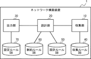
まず、図1を参照して、本実施の形態に係るネットワーク構築装置1の構成について説明する。図1は、本実施の形態に係るネットワーク構築装置1の構成例を示す図である。ネットワーク構築装置1は、対象のネットワークを仮想化した仮想ネットワークを構築するために使用されるものであり、収集部10と、設計部20と、出力部30と、収集ルールDB(Database。以下、同じ)40と、設計ルールDB50と、制約ルールDB60と、設定ルールDB70と、を備えている。なお、収集ルールDB40、設計ルールDB50、制約ルールDB60、及び設定ルールDB70は、ネットワーク構築装置1の内部に設けることには限定されず、ネットワーク構築装置1の外部に設けても良い。Hereinafter, embodiments of the present invention will be described with reference to the drawings.
First, the configuration of the
収集部10は、収集ルールDB40に登録された収集ルールに従って、対象のネットワークに接続された各ノードをスキャンして、そのネットワークの環境データを収集する。具体的には、収集部10は、各ノードに対し、ポートスキャンを実行することで、環境データを収集する。ノードは、対象のネットワークに接続されているクライアントPC(Personal computer)、ハブ、スイッチ、ルータ等である。
The
収集ルールは、例えば、収集する環境データの項目等を規定している。図2は、収集部10が収集する環境データの一例を示す図である。図2に示される環境データの項目は、ノードの役割(図中の「役割」)、そのノードで使用されているOS(図中の「OS」)、そのノードのバージョン(図中の「version」)、そのノードのIP(Internet Protocol)アドレス(図中の「IP Address」)となっている。収集部10は、例えば、対象のネットワークに接続された各ノードをスキャンして、そのネットワークの環境データとして、収集ルールで規定された項目のデータを収集する。
The collection rule defines, for example, items of environmental data to be collected. FIG. 2 is a diagram showing an example of environmental data collected by the
設計部20は、設計ルールDB50に登録された設計ルール及び制約ルールDB60に登録された制約ルールに従って、収集部10により収集された環境データに基づいて、対象のネットワークを仮想化した仮想ネットワークを設計する。なお、設計ルールDB50は、第1データベースの一例であり、設計ルールは、第1ルールの一例である。また、制約ルールDB60は、第3データベースの一例であり、制約ルールは、第3ルールの一例である。
The
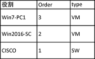
設計ルールは、ノードを仮想ネットワークに配置するときの順番や機器タイプ等を規定している。図3は、設計ルールDB50に登録された設計ルールの一例を示す図である。図3に示される設計ルールは、ノードの役割毎に、その役割のノードを仮想ネットワークに配置するときの順番(図中の「Order」)と機器タイプ(図中の「Type」)とを規定している。設計部20は、図3に示される設計ルールに従い、例えば、役割「CISCO」のノードについては、仮想ネットワークに配置するときの機器タイプが仮想スイッチ(「SW」)と判別し、仮想ネットワークに仮想スイッチとして最初に配置する。
The design rule defines the order in which the nodes are arranged in the virtual network, the device type, and the like. FIG. 3 is a diagram showing an example of design rules registered in the
制約ルールは、仮想ネットワークにおけるリソースの使用状況等を規定している。リソースは、例えば、VLAN(Virtual Local Area Network)、メモリ等である。本実施の形態では、複数のVLANを用いることで、複数の仮想ネットワークを同時に運用することが可能となる。図4は、制約ルールDB60に登録された制約ルールの一例を示す図である。図4に示される制約ルールは、ある仮想ネットワーク(ここでは、仮想ネットワーク#1とする)におけるVLANの使用状況を規定している。設計部20は、2つの仮想ネットワーク#1,#2を設計する場合、図4に示される制約ルールに従い、2つの仮想ネットワーク#1,#2間でVLANが重複しないように、仮想ネットワーク#2には、仮想ネットワーク#1で使用されていないVLANを割り当てる。なお、図4に示される制約ルールは、仮想ネットワーク#1におけるVLANの使用状況を規定したものとなっているが、制約ルールは、仮想ネットワーク毎に、その仮想ネットワークにおけるリソースの種別(VLANやメモリ)毎の使用状況を規定したものとなる。例えば、2つの仮想ネットワーク#1,#2があり、管理するリソースが2種類(VLANとメモリ)である場合は、制約ルールは、仮想ネットワーク#1におけるVLANの使用状況、仮想ネットワーク#1におけるメモリの使用状況、仮想ネットワーク#2におけるVLANの使用状況、及び仮想ネットワーク#2におけるメモリの使用状況を規定したものとなる。
The constraint rule prescribes the usage status of resources in the virtual network. The resource is, for example, a VLAN (Virtual Local Area Network), a memory, or the like. In this embodiment, a plurality of virtual networks can be operated simultaneously by using a plurality of VLANs. FIG. 4 is a diagram showing an example of the constraint rules registered in the
ここで、図5を参照して、本実施の形態に係る設計部20の動作について説明する。図5は、設計部20の一動作例を示す図である。ここでは、図3に示される設計ルールに従って、2つの仮想ネットワーク#1,#2を設計する例について説明する。また、管理するリソースはVLANの1種類であるとする。
Here, the operation of the
最初に、設計部20は、仮想ネットワーク#1を設計する。まず、設計部20は、図3に示される設計ルールに従って、仮想ネットワーク#1として設計するネットワークに接続されたノードのうち、順番(図中の「Order」)が「1」である役割「CISCO」のノードについて、機器タイプが仮想スイッチ(「SW」)であると判別し、仮想サーバ82に仮想スイッチ(#1)83−1として接続する。続いて、設計部20は、順番(図中の「Order」)が「2」である役割「Win2016-SC」のノードを、仮想スイッチ(#1)83−1に仮想マシン(VM:Virtual Machine)(#1)84−1として接続する。続いて、設計部20は、順番(図中の「Order」)が「3」である役割「Win7-PC1」のノードを、仮想スイッチ(#1)83−1に仮想マシン(#1)84−1として接続する。このようにして、設計部20は、仮想スイッチ(#1)83−1及び複数の仮想マシン(#1)84−1からなる仮想ネットワーク#1を設計する。また、設計部20は、仮想ネットワーク#1にVLANを割り当て、仮想ネットワーク#1におけるVLANの使用状況を規定する制約ルールを制約ルールDB60に登録する。ここで登録した制約ルールは、図4に示される制約ルールであるとして、以下、説明を行う。
First, the
続いて、設計部20は、仮想ネットワーク#1と同様の方法で、仮想スイッチ(#2)83−2及び複数の仮想マシン(#2)84−2からなる仮想ネットワーク#2を設計する。このとき、設計部20は、図4に示される制約ルールに従って、2つの仮想ネットワーク#1,#2間でVLANが重複しないように、仮想ネットワーク#2には、仮想ネットワーク#1で使用されていないVLAN(「VLAN ID」が「101」、「102」、「105」のVLAN)を割り当てる。また、設計部20は、仮想ネットワーク#2におけるVLANの使用状況を規定する制約ルールを制約ルールDB60に登録する。
Subsequently, the
なお、図5には図示されていないが、設計部20は、仮想スイッチ(#1)83−1及び仮想スイッチ(#2)83−2を物理スイッチ/OpenFlowスイッチ81に接続している。
Although not shown in FIG. 5, the
出力部30は、設計部20により設計された仮想ネットワークの設計データを特定の出力先に出力する。設計データの出力先は、仮想ネットワークとして設計したネットワークを評価する評価装置(不図示)における評価環境である。
The
また、出力部30は、仮想ネットワークの設計データを出力するときに、設定ルールDB70に登録された設定ルールに従って、仮想ネットワークとして設計したネットワークに接続されている各ノードにおけるアプリケーションのインストール手順を示す情報も出力する。なお、設定ルールDB70は、第2データベースの一例であり、設定ルールは、第2ルールの一例である。
Further, when outputting the design data of the virtual network, the
設定ルールは、アプリケーションのインストール手順を規定している。図6は、設定ルールDB70に登録された設定ルールの一例を示す図である。図6に示される設定ルールは、ノードの役割(図中の「役割」)毎に、その役割のノードにおけるアプリケーションをインストールするためのインストールコマンド(図中の「install command」)、その役割のノードで使用されているOS(図中の「OS」)、その役割のノードのバージョン(図中の「version」)を規定している。なお、図6は、アプリケーションのインストール手順の情報として、インストールコマンドを規定しているが、これには限定されず、インストールの手順が分かれば、その他の情報でも良い。出力部30は、図6に示される設定ルールに従い、例えば、役割「Apache」のノードについては、インストールコマンドが「apt-get install apache2」と判別し、インストールコマンド「apt-get install apache2」を評価装置に出力する。なお、インストールコマンド「apt-get install apache2」を出力するときは、役割「Apache」のノードに対応する仮想マシンと対応付けされることを示す情報も出力するのが良い。
The setting rule defines the application installation procedure. FIG. 6 is a diagram showing an example of the setting rules registered in the
そのため、評価装置(又は評価装置を操作する評価者)は、仮想ネットワークを構成する仮想マシンにインストールするアプリケーションや、そのアプリケーションのインストール手順を調査することなく、仮想マシンにアプリケーションをインストールすることができるようになる。 Therefore, the evaluation device (or the evaluator who operates the evaluation device) can install the application in the virtual machine without investigating the application to be installed in the virtual machine configuring the virtual network and the installation procedure of the application. Like
続いて、図7を参照して、本実施の形態に係るネットワーク構築装置1の処理フローについて説明する。図7は、本実施の形態に係るネットワーク構築装置1の処理フローの一例を示すフロー図である。
Next, with reference to FIG. 7, a processing flow of the
まず、収集部10は、収集ルールDB40に登録された収集ルールに従って、対象のネットワークに接続された各ノードをスキャンして、そのネットワークの環境データを収集する(ステップS1)。
First, the
続いて、設計部20は、設計ルールDB50に登録された設計ルール及び制約ルールDB60に登録された制約ルールに従って、収集部10により収集された環境データに基づいて、対象のネットワークを仮想化した仮想ネットワークを設計する(ステップS2)。
Then, the
その後、出力部30は、設定ルールDB70に登録された設定ルールに従って、設計部20により設計された仮想ネットワークの設計データを出力すると共に、仮想ネットワークとして設計したネットワークに接続されている各ノードにおけるアプリケーションのインストール手順を示す情報を出力する(ステップS3)。
After that, the
上述したように、本実施の形態に係るネットワーク構築装置1によれば、収集部10は、対象のネットワークに接続された各ノードをスキャンして、そのネットワークの環境データを収集する。これにより、仮想ネットワークを構築するために必要な環境データ、例えば、各ノードの役割やOSのデータ等を、容易に収集することができる。
As described above, according to the
また、設定ルールDB70は、ノードの役割毎に、その役割のノードにおけるアプリケーションのインストール手順を示す設定ルールを登録する。また、出力部30は、仮想ネットワークの設計データを出力するときに、設定ルールDB70に登録された設定ルールに従って、仮想ネットワークとして設計したネットワークに接続されている各ノードにおけるアプリケーションのインストール手順を示す情報も出力する。これにより、出力先の評価装置(又は評価装置を操作する評価者)は、仮想ネットワークを構成する仮想マシンにインストールするアプリケーションや、そのアプリケーションのインストール手順を調査することなく、仮想マシンにアプリケーションをインストールすることができるようになる。
In addition, the
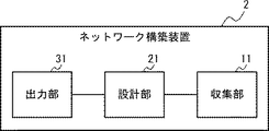
以下、図8を参照して、本発明のネットワーク構築装置の概要を説明する。図8は、本発明に係るネットワーク構築装置2の構成例を示す図である。ネットワーク構築装置2は、収集部11と、設計部21と、出力部31と、を備えている。
The outline of the network construction apparatus of the present invention will be described below with reference to FIG. FIG. 8 is a diagram showing a configuration example of the
収集部11は、対象のネットワークに接続された各ノードをスキャンして、そのネットワークの環境データを収集する。収集部11は、収集部10に対応する。
The
設計部21は、収集部11により収集された環境データに基づいて、対象のネットワークを仮想化した仮想ネットワークを設計する。設計部21は、設計部20に対応する。
The
出力部31は、設計部20により設計された仮想ネットワークの設計データを出力する。出力部31は、出力部30に対応する。
The
上述したように、本発明に係るネットワーク構築装置2によれば、収集部11は、対象のネットワークに接続された各ノードをスキャンして、そのネットワークの環境データを収集する。これにより、仮想ネットワークを構築するために必要な環境データを容易に収集することができる。
As described above, according to the
以上、実施の形態を参照して本願発明における様々な観点を説明したが、本願発明は上記によって限定されるものではない。本願発明の各観点における構成や詳細には、発明のスコープ内で当業者が理解し得る様々な変更をすることができる。 Although various aspects of the present invention have been described with reference to the exemplary embodiments, the present invention is not limited to the above. Various modifications that can be understood by those skilled in the art can be made to the configurations and details of the respective aspects of the present invention within the scope of the invention.
例えば、上記の実施の形態では、各機能ブロック(収集部、設計部、及び出力部)は、同じ装置内に設けられていたが、これには限定されない。これら機能ブロックは、別々の装置に設けられ、有線又は無線により相互に接続されていても良い。 For example, in the above embodiment, each functional block (collection unit, design unit, and output unit) was provided in the same device, but the present invention is not limited to this. These functional blocks may be provided in separate devices and may be connected to each other by wire or wirelessly.
また、上記の実施の形態における各機能ブロックは、ハードウェア又はソフトウェア、もしくはその両方によって構成され、1つのハードウェア又はソフトウェアから構成しても良いし、複数のハードウェア又はソフトウェアから構成しても良い。各装置の機能(処理)を、CPU(Central Processing Unit)やメモリ等を有するコンピュータにより実現しても良い。例えば、メモリに実施の形態におけるネットワーク構築方法を行うためのプログラムを格納し、各機能を、メモリに格納されたプログラムをCPUで実行することにより実現しても良い。 Further, each functional block in the above-described embodiment is configured by hardware or software, or both, and may be configured by one piece of hardware or software, or may be configured by a plurality of hardware or software. good. The function (processing) of each device may be realized by a computer having a CPU (Central Processing Unit), a memory, and the like. For example, a program for performing the network construction method according to the embodiment may be stored in the memory, and each function may be realized by executing the program stored in the memory by the CPU.
また、上記のプログラムは、様々なタイプの非一時的なコンピュータ可読媒体(non-transitory computer readable medium)を用いて格納され、コンピュータに供給することができる。非一時的なコンピュータ可読媒体は、様々なタイプの実体のある記録媒体(tangible storage medium)を含む。非一時的なコンピュータ可読媒体の例は、磁気記録媒体(例えば、フレキシブルディスク、磁気テープ、ハードディスクドライブ)、光磁気記録媒体(例えば、光磁気ディスク)、CD−ROM(compact disc read only memory)、CD−R(compact disc recordable)、CD−R/W(compact disc rewritable)、半導体メモリ(例えば、マスクROM、PROM(programmable ROM)、EPROM(erasable PROM)、フラッシュROM、RAM(random access memory))を含む。また、プログラムは、様々なタイプの一時的なコンピュータ可読媒体(transitory computer readable medium)によってコンピュータに供給されても良い。一時的なコンピュータ可読媒体の例は、電気信号、光信号、及び電磁波を含む。一時的なコンピュータ可読媒体は、電線及び光ファイバ等の有線通信路、又は無線通信路を介して、プログラムをコンピュータに供給できる。 Further, the above program can be stored using various types of non-transitory computer readable media and supplied to the computer. Non-transitory computer readable media include various types of tangible storage media. Examples of non-transitory computer readable media include magnetic recording media (eg, flexible disk, magnetic tape, hard disk drive), magneto-optical recording media (eg, magneto-optical disk), CD-ROM (compact disc read only memory), CD-R (compact disc recordable), CD-R/W (compact disc rewritable), semiconductor memory (for example, mask ROM, PROM (programmable ROM), EPROM (erasable PROM), flash ROM, RAM (random access memory)) including. In addition, the program may be supplied to the computer by various types of transitory computer readable media. Examples of transitory computer-readable media include electrical signals, optical signals, and electromagnetic waves. The transitory computer-readable medium can supply the program to the computer via a wired communication path such as an electric wire and an optical fiber, or a wireless communication path.
また、上述の実施形態の一部または全部は、以下の付記のようにも記載されうるが、以下には限られない。
(付記1)
ネットワークに接続された各ノードをスキャンして、前記ネットワークの環境データを収集する収集部と、
前記収集部により収集された前記環境データに基づいて、前記ネットワークを仮想化した仮想ネットワークを設計する設計部と、
前記設計部により設計された前記仮想ネットワークの設計データを出力する出力部と、
を備える、ネットワーク構築装置。
(付記2)
前記ノードの役割毎に、当該役割の前記ノードを前記仮想ネットワークに配置するときの機器タイプを示す第1ルールが第1データベースに格納されており、
前記収集部は、
前記ネットワークの環境データとして、前記ネットワークに接続された各ノードの役割を示すデータを少なくとも収集し、
前記設計部は、
前記第1ルールに基づいて、前記ネットワークに接続された各ノードの役割に応じた前記機器タイプを判別し、
前記ネットワークに接続された各ノードを、前記判別した機器タイプの機器として、前記仮想ネットワークに配置する、
付記1に記載のネットワーク構築装置。
(付記3)
前記ノードの役割毎に、当該役割の前記ノードにおけるアプリケーションのインストール手順を示す第2ルールが第2データベースに格納されており、
前記出力部は、
前記第2ルールに基づいて、前記ネットワークに接続された各ノードの役割に応じた前記インストール手順を判別し、
前記仮想ネットワークの設計データを出力するときに、前記ネットワークに接続された各ノードにおける前記インストール手順の情報も出力する、
付記2に記載のネットワーク構築装置。
(付記4)
前記仮想ネットワーク毎に、当該仮想ネットワークにおけるリソースの使用状況を示す第3ルールが第3データベースに格納されており、
前記設計部は、
複数の前記仮想ネットワークを設計する場合、前記第3ルールに基づいて、複数の前記仮想ネットワーク間でリソースが重複しないように、複数の前記仮想ネットワークの各々にリソースを割り当てる、
付記1から3のいずれか1項に記載のネットワーク構築装置。
(付記5)
ネットワーク構築装置によるネットワーク構築方法であって、
ネットワークに接続された各ノードをスキャンして、前記ネットワークの環境データを収集する収集ステップと、
前記収集ステップにより収集された前記環境データに基づいて、前記ネットワークを仮想化した仮想ネットワークを設計する設計ステップと、
前記設計ステップにより設計された前記仮想ネットワークの設計データを出力する出力ステップと、
を含む、ネットワーク構築方法。
(付記6)
前記ノードの役割毎に、当該役割の前記ノードを前記仮想ネットワークに配置するときの機器タイプを示す第1ルールが第1データベースに格納されており、
前記収集ステップでは、
前記ネットワークの環境データとして、前記ネットワークに接続された各ノードの役割を示すデータを少なくとも収集し、
前記設計ステップでは、
前記第1ルールに基づいて、前記ネットワークに接続された各ノードの役割に応じた前記機器タイプを判別し、
前記ネットワークに接続された各ノードを、前記判別した機器タイプの機器として、前記仮想ネットワークに配置する、
付記5に記載のネットワーク構築方法。
(付記7)
前記ノードの役割毎に、当該役割の前記ノードにおけるアプリケーションのインストール手順を示す第2ルールが第2データベースに格納されており、
前記出力ステップでは、
前記第2ルールに基づいて、前記ネットワークに接続された各ノードの役割に応じた前記インストール手順を判別し、
前記仮想ネットワークの設計データを出力するときに、前記ネットワークに接続された各ノードにおける前記インストール手順の情報も出力する、
付記6に記載のネットワーク構築方法。
(付記8)
前記仮想ネットワーク毎に、当該仮想ネットワークにおけるリソースの使用状況を示す第3ルールが第3データベースに格納されており、
前記設計ステップでは、
複数の前記仮想ネットワークを設計する場合、前記第3ルールに基づいて、複数の前記仮想ネットワーク間でリソースが重複しないように、複数の前記仮想ネットワークの各々にリソースを割り当てる、
付記5から7のいずれか1項に記載のネットワーク構築方法。
(付記9)
コンピュータに、
ネットワークに接続された各ノードをスキャンして、前記ネットワークの環境データを収集する収集手順と、
前記収集手順により収集された前記環境データに基づいて、前記ネットワークを仮想化した仮想ネットワークを設計する設計手順と、
前記設計手順により設計された前記仮想ネットワークの設計データを出力する出力手順と、
を実行させるためのプログラム。
(付記10)
前記ノードの役割毎に、当該役割の前記ノードを前記仮想ネットワークに配置するときの機器タイプを示す第1ルールが第1データベースに格納されており、
前記収集手順では、
前記ネットワークの環境データとして、前記ネットワークに接続された各ノードの役割を示すデータを少なくとも収集し、
前記設計手順では、
前記第1ルールに基づいて、前記ネットワークに接続された各ノードの役割に応じた前記機器タイプを判別し、
前記ネットワークに接続された各ノードを、前記判別した機器タイプの機器として、前記仮想ネットワークに配置する、
付記9に記載のプログラム。
(付記11)
前記ノードの役割毎に、当該役割の前記ノードにおけるアプリケーションのインストール手順を示す第2ルールが第2データベースに格納されており、
前記出力手順では、
前記第2ルールに基づいて、前記ネットワークに接続された各ノードの役割に応じた前記インストール手順を判別し、
前記仮想ネットワークの設計データを出力するときに、前記ネットワークに接続された各ノードにおける前記インストール手順の情報も出力する、
付記10に記載のプログラム。
(付記12)
前記仮想ネットワーク毎に、当該仮想ネットワークにおけるリソースの使用状況を示す第3ルールが第3データベースに格納されており、
前記設計手順では、
複数の前記仮想ネットワークを設計する場合、前記第3ルールに基づいて、複数の前記仮想ネットワーク間でリソースが重複しないように、複数の前記仮想ネットワークの各々にリソースを割り当てる、
付記9から11のいずれか1項に記載のプログラム。Further, part or all of the above-described exemplary embodiment can be described as the following supplementary notes, but is not limited to the following.
(Appendix 1)
A collection unit that scans each node connected to the network and collects environmental data of the network,
A design unit for designing a virtual network that virtualizes the network based on the environmental data collected by the collection unit;
An output unit for outputting design data of the virtual network designed by the design unit;
A network construction device comprising:
(Appendix 2)
A first rule indicating, for each role of the node, a device type when the node having the role is arranged in the virtual network is stored in the first database,
The collecting unit is
As environmental data of the network, at least data indicating the role of each node connected to the network is collected,
The design unit is
Based on the first rule, determine the device type according to the role of each node connected to the network,
Arranging each node connected to the network in the virtual network as a device of the determined device type,
The network construction device according to
(Appendix 3)
A second rule indicating, for each role of the node, an installation procedure of an application in the node having the role is stored in a second database,
The output unit is
Based on the second rule, determine the installation procedure according to the role of each node connected to the network,
When outputting the design data of the virtual network, the information of the installation procedure in each node connected to the network is also output.
The network construction device according to
(Appendix 4)
A third rule indicating the usage status of resources in the virtual network is stored in the third database for each virtual network,
The design unit is
When designing a plurality of the virtual networks, a resource is allocated to each of the plurality of virtual networks based on the third rule so that the resources do not overlap among the plurality of virtual networks,
4. The network construction device according to any one of
(Appendix 5)
A network construction method using a network construction device,
A collecting step of scanning each node connected to the network to collect environmental data of the network;
A design step of designing a virtual network that is a virtualized version of the network based on the environmental data collected by the collecting step;
An output step of outputting design data of the virtual network designed by the design step;
A network construction method including.
(Appendix 6)
A first rule indicating, for each role of the node, a device type when the node having the role is arranged in the virtual network is stored in the first database,
In the collecting step,
As environmental data of the network, at least data indicating the role of each node connected to the network is collected,
In the design step,
Based on the first rule, determine the device type according to the role of each node connected to the network,
Arranging each node connected to the network in the virtual network as a device of the determined device type,
The network construction method according to attachment 5.
(Appendix 7)
A second rule indicating, for each role of the node, an installation procedure of an application in the node having the role is stored in a second database,
In the output step,
Based on the second rule, determine the installation procedure according to the role of each node connected to the network,
When outputting the design data of the virtual network, the information of the installation procedure in each node connected to the network is also output.
The network construction method according to attachment 6.
(Appendix 8)
A third rule indicating the usage status of resources in the virtual network is stored in the third database for each virtual network,
In the design step,
When designing a plurality of the virtual networks, a resource is allocated to each of the plurality of virtual networks based on the third rule so that resources do not overlap between the plurality of virtual networks.
8. The network construction method according to any one of appendices 5 to 7.
(Appendix 9)
On the computer,
A collection procedure for scanning each node connected to the network and collecting environmental data of the network;
A design procedure for designing a virtual network by virtualizing the network based on the environmental data collected by the collection procedure;
An output procedure for outputting design data of the virtual network designed by the design procedure;
A program to execute.
(Appendix 10)
A first rule indicating, for each role of the node, a device type when the node having the role is arranged in the virtual network is stored in the first database,
In the collection procedure,
As environmental data of the network, at least data indicating the role of each node connected to the network is collected,
In the design procedure,
Based on the first rule, determine the device type according to the role of each node connected to the network,
Arranging each node connected to the network in the virtual network as a device of the determined device type,
The program according to Appendix 9.
(Appendix 11)
A second rule indicating, for each role of the node, an installation procedure of an application in the node having the role is stored in a second database,
In the output procedure,
Based on the second rule, determine the installation procedure according to the role of each node connected to the network,
When outputting the design data of the virtual network, the information of the installation procedure in each node connected to the network is also output.
The program according to
(Appendix 12)
A third rule indicating the usage status of the resource in the virtual network is stored in the third database for each virtual network,
In the design procedure,
When designing a plurality of the virtual networks, a resource is allocated to each of the plurality of virtual networks based on the third rule so that resources do not overlap between the plurality of virtual networks.
12. The program according to any one of appendices 9 to 11.
この出願は、2017年3月31日に出願された日本出願特願2017−070503を基礎とする優先権を主張し、その開示の全てをここに取り込む。 This application claims the priority on the basis of Japanese application Japanese Patent Application No. 2017-070503 for which it applied on March 31, 2017, and takes in those the indications of all here.
1 ネットワーク構築装置
10 収集部
20 設計部
30 出力部
40 収集ルールDB
50 設計ルールDB
60 制約ルールDB
70 設定ルールDB
2 ネットワーク構築装置
11 収集部
21 設計部
31 出力部1
50 Design Rule DB
60 constraint rule DB
70 Setting rule DB
2
Claims (8)
前記収集部により収集された前記環境データに基づいて、前記ネットワークを仮想化した仮想ネットワークを設計する設計部と、
前記設計部により設計された前記仮想ネットワークの設計データを出力する出力部と、
を備え、
前記ノードの役割毎に、当該役割の前記ノードを前記仮想ネットワークに配置するときの機器タイプを示す第1ルールが第1データベースに格納されており、
前記収集部は、
前記ネットワークの環境データとして、前記ネットワークに接続された各ノードの役割を示すデータを少なくとも収集し、
前記設計部は、
前記第1ルールに基づいて、前記ネットワークに接続された各ノードの役割に応じた前記機器タイプを判別し、
前記ネットワークに接続された各ノードを、前記判別した機器タイプの機器として、前記仮想ネットワークに配置する、
ネットワーク構築装置。 A collection unit that scans each node connected to the network and collects environmental data of the network,
A design unit for designing a virtual network that virtualizes the network based on the environmental data collected by the collection unit;
An output unit for outputting design data of the virtual network designed by the design unit;
Equipped with
The first database stores, for each role of the node, a first rule indicating a device type when the node having the role is arranged in the virtual network,
The collecting unit is
As environmental data of the network, at least data indicating the role of each node connected to the network is collected,
The design unit is
Based on the first rule, determine the device type according to the role of each node connected to the network,
Arranging each node connected to the network in the virtual network as a device of the determined device type,
Network construction equipment.
前記出力部は、
前記第2ルールに基づいて、前記ネットワークに接続された各ノードの役割に応じた前記インストール手順を判別し、
前記仮想ネットワークの設計データを出力するときに、前記ネットワークに接続された各ノードにおける前記インストール手順の情報も出力する、
請求項1に記載のネットワーク構築装置。 A second rule indicating, for each role of the node, an installation procedure of an application in the node having the role is stored in a second database,
The output unit is
Based on the second rule, determine the installation procedure according to the role of each node connected to the network,
When outputting the design data of the virtual network, the information of the installation procedure in each node connected to the network is also output.
The network construction device according to claim 1 .
前記収集部により収集された前記環境データに基づいて、前記ネットワークを仮想化した仮想ネットワークを設計する設計部と、
前記設計部により設計された前記仮想ネットワークの設計データを出力する出力部と、
を備え、
前記仮想ネットワーク毎に、当該仮想ネットワークにおけるリソースの使用状況を示す第3ルールが第3データベースに格納されており、
前記設計部は、
複数の前記仮想ネットワークを設計する場合、前記第3ルールに基づいて、複数の前記仮想ネットワーク間でリソースが重複しないように、複数の前記仮想ネットワークの各々にリソースを割り当てる、
ネットワーク構築装置。 A collection unit that scans each node connected to the network and collects environmental data of the network,
A design unit for designing a virtual network that virtualizes the network based on the environmental data collected by the collection unit;
An output unit for outputting design data of the virtual network designed by the design unit;
Equipped with
A third rule indicating the usage status of resources in the virtual network is stored in the third database for each virtual network,
The design unit is
When designing a plurality of the virtual networks, a resource is allocated to each of the plurality of virtual networks based on the third rule so that the resources do not overlap among the plurality of virtual networks,
Network construction apparatus.
ネットワークに接続された各ノードをスキャンして、前記ネットワークの環境データを収集する収集ステップと、
前記収集ステップにより収集された前記環境データに基づいて、前記ネットワークを仮想化した仮想ネットワークを設計する設計ステップと、
前記設計ステップにより設計された前記仮想ネットワークの設計データを出力する出力ステップと、
を含み、
前記ノードの役割毎に、当該役割の前記ノードを前記仮想ネットワークに配置するときの機器タイプを示す第1ルールが第1データベースに格納されており、
前記収集ステップでは、
前記ネットワークの環境データとして、前記ネットワークに接続された各ノードの役割を示すデータを少なくとも収集し、
前記設計ステップでは、
前記第1ルールに基づいて、前記ネットワークに接続された各ノードの役割に応じた前記機器タイプを判別し、
前記ネットワークに接続された各ノードを、前記判別した機器タイプの機器として、前記仮想ネットワークに配置する、
ネットワーク構築方法。 A network construction method using a network construction device,
A collecting step of scanning each node connected to the network to collect environmental data of the network;
A design step of designing a virtual network that is a virtualized version of the network based on the environmental data collected by the collecting step;
An output step of outputting design data of the virtual network designed by the design step;
Only including,
The first database stores, for each role of the node, a first rule indicating a device type when the node having the role is arranged in the virtual network,
In the collecting step,
As environmental data of the network, at least data indicating the role of each node connected to the network is collected,
In the design step,
Based on the first rule, determine the device type according to the role of each node connected to the network,
Arranging each node connected to the network in the virtual network as a device of the determined device type,
Network construction method.
前記出力ステップでは、
前記第2ルールに基づいて、前記ネットワークに接続された各ノードの役割に応じた前記インストール手順を判別し、
前記仮想ネットワークの設計データを出力するときに、前記ネットワークに接続された各ノードにおける前記インストール手順の情報も出力する、
請求項4に記載のネットワーク構築方法。 A second rule indicating, for each role of the node, an installation procedure of an application in the node of the role is stored in a second database,
In the output step,
Based on the second rule, determine the installation procedure according to the role of each node connected to the network,
When outputting the design data of the virtual network, the information of the installation procedure in each node connected to the network is also output.
The network construction method according to claim 4 .
ネットワークに接続された各ノードをスキャンして、前記ネットワークの環境データを収集する収集ステップと、
前記収集ステップにより収集された前記環境データに基づいて、前記ネットワークを仮想化した仮想ネットワークを設計する設計ステップと、
前記設計ステップにより設計された前記仮想ネットワークの設計データを出力する出力ステップと、
を含み、
前記仮想ネットワーク毎に、当該仮想ネットワークにおけるリソースの使用状況を示す第3ルールが第3データベースに格納されており、
前記設計ステップでは、
複数の前記仮想ネットワークを設計する場合、前記第3ルールに基づいて、複数の前記仮想ネットワーク間でリソースが重複しないように、複数の前記仮想ネットワークの各々にリソースを割り当てる、
ネットワーク構築方法。 A network construction method using a network construction device,
A collecting step of scanning each node connected to the network to collect environmental data of the network;
A design step of designing a virtual network that is a virtualized version of the network based on the environmental data collected by the collecting step;
An output step of outputting design data of the virtual network designed by the design step;
Including,
A third rule indicating the usage status of resources in the virtual network is stored in the third database for each virtual network,
In the design step,
When designing a plurality of the virtual networks, a resource is allocated to each of the plurality of virtual networks based on the third rule so that the resources do not overlap among the plurality of virtual networks,
Network construction method.
ネットワークに接続された各ノードをスキャンして、前記ネットワークの環境データを収集する収集手順と、
前記収集手順により収集された前記環境データに基づいて、前記ネットワークを仮想化した仮想ネットワークを設計する設計手順と、
前記設計手順により設計された前記仮想ネットワークの設計データを出力する出力手順と、
を実行させるためのプログラムであって、
前記ノードの役割毎に、当該役割の前記ノードを前記仮想ネットワークに配置するときの機器タイプを示す第1ルールが第1データベースに格納されており、
前記収集手順では、
前記ネットワークの環境データとして、前記ネットワークに接続された各ノードの役割を示すデータを少なくとも収集し、
前記設計手順では、
前記第1ルールに基づいて、前記ネットワークに接続された各ノードの役割に応じた前記機器タイプを判別し、
前記ネットワークに接続された各ノードを、前記判別した機器タイプの機器として、前記仮想ネットワークに配置する、
プログラム。 On the computer,
A collection procedure for scanning each node connected to the network and collecting environmental data of the network;
A design procedure for designing a virtual network by virtualizing the network based on the environmental data collected by the collection procedure;
An output procedure for outputting design data of the virtual network designed by the design procedure;
A program for executing,
A first rule indicating, for each role of the node, a device type when the node having the role is arranged in the virtual network is stored in the first database,
In the collection procedure,
As environmental data of the network, at least data indicating the role of each node connected to the network is collected,
In the design procedure,
Based on the first rule, determine the device type according to the role of each node connected to the network,
Arranging each node connected to the network in the virtual network as a device of the determined device type,
program.
ネットワークに接続された各ノードをスキャンして、前記ネットワークの環境データを収集する収集手順と、 A collection procedure for scanning each node connected to the network and collecting environmental data of the network;
前記収集手順により収集された前記環境データに基づいて、前記ネットワークを仮想化した仮想ネットワークを設計する設計手順と、 A design procedure for designing a virtual network by virtualizing the network based on the environmental data collected by the collection procedure;
前記設計手順により設計された前記仮想ネットワークの設計データを出力する出力手順と、 An output procedure for outputting design data of the virtual network designed by the design procedure;
を実行させるためのプログラムであって、 Is a program for executing
前記仮想ネットワーク毎に、当該仮想ネットワークにおけるリソースの使用状況を示す第3ルールが第3データベースに格納されており、 A third rule indicating the usage status of resources in the virtual network is stored in the third database for each virtual network,
前記設計手順では、 In the design procedure,
複数の前記仮想ネットワークを設計する場合、前記第3ルールに基づいて、複数の前記仮想ネットワーク間でリソースが重複しないように、複数の前記仮想ネットワークの各々にリソースを割り当てる、 When designing a plurality of the virtual networks, a resource is allocated to each of the plurality of virtual networks based on the third rule so that the resources do not overlap among the plurality of virtual networks,
プログラム。 program.
Applications Claiming Priority (3)
| Application Number | Priority Date | Filing Date | Title |
|---|---|---|---|
| JP2017070503 | 2017-03-31 | ||
| JP2017070503 | 2017-03-31 | ||
| PCT/JP2017/045785 WO2018179627A1 (en) | 2017-03-31 | 2017-12-20 | Network architecture device, network architecture method, and non-temporary computer-readable medium on which program is stored |
Related Child Applications (1)
| Application Number | Title | Priority Date | Filing Date |
|---|---|---|---|
| JP2020128755A Division JP6992854B2 (en) | 2017-03-31 | 2020-07-30 | Network construction device, network construction method, and program |
Publications (2)
| Publication Number | Publication Date |
|---|---|
| JPWO2018179627A1 JPWO2018179627A1 (en) | 2019-12-12 |
| JP6747579B2 true JP6747579B2 (en) | 2020-08-26 |
Family
ID=63674976
Family Applications (4)
| Application Number | Title | Priority Date | Filing Date |
|---|---|---|---|
| JP2019508573A Active JP6747579B2 (en) | 2017-03-31 | 2017-12-20 | Network construction device, network construction method, and program |
| JP2020128755A Active JP6992854B2 (en) | 2017-03-31 | 2020-07-30 | Network construction device, network construction method, and program |
| JP2021198210A Active JP7168060B2 (en) | 2017-03-31 | 2021-12-07 | NETWORK CONSTRUCTION DEVICE, NETWORK CONSTRUCTION METHOD, AND PROGRAM |
| JP2022171137A Pending JP2022186912A (en) | 2017-03-31 | 2022-10-26 | Node construction device, node construction method, and program |
Family Applications After (3)
| Application Number | Title | Priority Date | Filing Date |
|---|---|---|---|
| JP2020128755A Active JP6992854B2 (en) | 2017-03-31 | 2020-07-30 | Network construction device, network construction method, and program |
| JP2021198210A Active JP7168060B2 (en) | 2017-03-31 | 2021-12-07 | NETWORK CONSTRUCTION DEVICE, NETWORK CONSTRUCTION METHOD, AND PROGRAM |
| JP2022171137A Pending JP2022186912A (en) | 2017-03-31 | 2022-10-26 | Node construction device, node construction method, and program |
Country Status (5)
| Country | Link |
|---|---|
| US (2) | US11075815B2 (en) |
| JP (4) | JP6747579B2 (en) |
| KR (1) | KR20190116512A (en) |
| CN (1) | CN110546924A (en) |
| WO (1) | WO2018179627A1 (en) |
Families Citing this family (2)
| Publication number | Priority date | Publication date | Assignee | Title |
|---|---|---|---|---|
| US11537386B2 (en) * | 2020-04-06 | 2022-12-27 | Johnson Controls Tyco IP Holdings LLP | Building system with dynamic configuration of network resources for 5G networks |
| US11456917B2 (en) * | 2020-06-01 | 2022-09-27 | Cisco Technology, Inc. | Analyzing deployed networks with respect to network solutions |
Family Cites Families (39)
| Publication number | Priority date | Publication date | Assignee | Title |
|---|---|---|---|---|
| JP2830766B2 (en) | 1994-02-24 | 1998-12-02 | ヤマハ株式会社 | Network construction method |
| WO1996013107A1 (en) * | 1994-10-25 | 1996-05-02 | Cabletron Systems, Inc. | Method and apparatus for automatically populating a network simulator tool |
| JPH08328984A (en) * | 1995-05-31 | 1996-12-13 | Matsushita Electric Works Ltd | Network management system |
| US6862564B1 (en) * | 2000-10-26 | 2005-03-01 | Sycamore Networks, Inc. | Network emulator |
| US7120680B1 (en) * | 2002-07-15 | 2006-10-10 | Sun Microsystems, Inc. | Methods and apparatus for identifying network configurations in an existing network |
| EP1579716B1 (en) * | 2002-12-17 | 2014-09-03 | Girish P. Saraph | Routing scheme based on virtual space representation |
| US20040210623A1 (en) | 2003-03-06 | 2004-10-21 | Aamer Hydrie | Virtual network topology generation |
| US7703018B2 (en) * | 2003-05-22 | 2010-04-20 | International Business Machines Corporation | Apparatus and method for automating the diagramming of virtual local area networks |
| US7912940B2 (en) * | 2004-07-30 | 2011-03-22 | Microsoft Corporation | Network system role determination |
| US20060090136A1 (en) * | 2004-10-01 | 2006-04-27 | Microsoft Corporation | Methods and apparatus for implementing a virtualized computer system |
| US7555421B1 (en) * | 2005-10-28 | 2009-06-30 | At&T Corp. | Device emulation for testing data network configurations |
| JP2007208633A (en) | 2006-02-01 | 2007-08-16 | Mitsubishi Electric Corp | Device, method and program for designing network |
| US8824282B2 (en) * | 2006-08-15 | 2014-09-02 | Riverbed Technology, Inc. | Network simulation and analysis using operational forwarding data |
| US20080123586A1 (en) * | 2006-08-29 | 2008-05-29 | Manser David B | Visualization of ad hoc network nodes |
| US7729287B2 (en) * | 2006-11-10 | 2010-06-01 | At&T Intellectual Property I, L.P. | Methods of providing simulation for communications systems and related systems and computer program products |
| JP2008165688A (en) | 2007-01-05 | 2008-07-17 | Fujitsu Ltd | Network management apparatus |
| US20110004564A1 (en) * | 2007-12-20 | 2011-01-06 | Jerome Rolia | Model Based Deployment Of Computer Based Business Process On Dedicated Hardware |
| US8793117B1 (en) * | 2008-04-16 | 2014-07-29 | Scalable Network Technologies, Inc. | System and method for virtualization of networking system software via emulation |
| US20090319906A1 (en) * | 2008-06-18 | 2009-12-24 | Eads Na Defense Security And Systems Solutions Inc | Systems and methods for reconstitution of network elements in a simulated network |
| US8260588B2 (en) * | 2009-10-16 | 2012-09-04 | Oracle America, Inc. | Virtualizing complex network topologies |
| US8458314B1 (en) * | 2009-10-30 | 2013-06-04 | Bradford Networks, Inc. | System and method for offloading IT network tasks |
| WO2012025773A1 (en) * | 2010-08-25 | 2012-03-01 | Telefonaktiebolaget L M Ericsson (Publ) | Infrastructure model generation system and method |
| JP5836042B2 (en) * | 2011-10-04 | 2015-12-24 | 株式会社日立製作所 | Management server program |
| US8943499B2 (en) * | 2012-04-30 | 2015-01-27 | Hewlett-Packard Development Company, L.P. | Providing a virtual network topology in a data center |
| US9146837B2 (en) * | 2012-05-23 | 2015-09-29 | Landis+Gyr Innovations, Inc. | Automated build, deploy, and testing environment for firmware |
| US9697172B1 (en) * | 2012-12-28 | 2017-07-04 | Juniper Networks, Inc. | Virtual network optimizing a physical network |
| JP2014154925A (en) * | 2013-02-05 | 2014-08-25 | Nomura Research Institute Ltd | Network verification system |
| CA2908087A1 (en) * | 2013-03-28 | 2014-10-02 | Sphere 3D Inc. | Systems and methods for providing an emulator |
| US9600386B1 (en) * | 2013-05-31 | 2017-03-21 | Sandia Corporation | Network testbed creation and validation |
| JP2015022501A (en) | 2013-07-18 | 2015-02-02 | 富士通株式会社 | Construction device, construction method, and construction program |
| CN104349319B (en) * | 2013-08-01 | 2018-10-30 | 华为终端(东莞)有限公司 | A kind of method, apparatus and system for configuring more equipment |
| US9116874B2 (en) | 2013-09-25 | 2015-08-25 | Hitachi, Ltd. | Virtual machine test system, virtual machine test method |
| JP5750175B1 (en) | 2014-02-20 | 2015-07-15 | 日本電信電話株式会社 | Network simulator and network simulation method |
| US11303539B2 (en) * | 2014-12-05 | 2022-04-12 | Accenture Global Services Limited | Network component placement architecture |
| US10411966B2 (en) * | 2015-02-26 | 2019-09-10 | Red Hat, Inc. | Host network analyzer |
| WO2017017937A1 (en) * | 2015-07-27 | 2017-02-02 | 日本電気株式会社 | Deployment device, deployment method, and recording medium |
| US10164843B2 (en) | 2015-09-21 | 2018-12-25 | Ruby Tech Corporation | Network switch, device management system, and device management method thereof |
| US10749857B2 (en) * | 2016-09-26 | 2020-08-18 | Expanse, Inc. | Network mapping using a fingerprint |
| US10560370B1 (en) * | 2017-03-31 | 2020-02-11 | Juniper Networks, Inc. | Intelligent exception recovery in network services |
-
2017
- 2017-12-20 JP JP2019508573A patent/JP6747579B2/en active Active
- 2017-12-20 KR KR1020197028086A patent/KR20190116512A/en not_active Application Discontinuation
- 2017-12-20 US US16/490,682 patent/US11075815B2/en active Active
- 2017-12-20 CN CN201780089281.4A patent/CN110546924A/en active Pending
- 2017-12-20 WO PCT/JP2017/045785 patent/WO2018179627A1/en active Application Filing
-
2020
- 2020-07-30 JP JP2020128755A patent/JP6992854B2/en active Active
-
2021
- 2021-06-25 US US17/358,763 patent/US20210377129A1/en not_active Abandoned
- 2021-12-07 JP JP2021198210A patent/JP7168060B2/en active Active
-
2022
- 2022-10-26 JP JP2022171137A patent/JP2022186912A/en active Pending
Also Published As
| Publication number | Publication date |
|---|---|
| JP2022186912A (en) | 2022-12-15 |
| US20200007407A1 (en) | 2020-01-02 |
| JP2022028932A (en) | 2022-02-16 |
| US11075815B2 (en) | 2021-07-27 |
| JP2020174412A (en) | 2020-10-22 |
| JP6992854B2 (en) | 2022-01-13 |
| KR20190116512A (en) | 2019-10-14 |
| JP7168060B2 (en) | 2022-11-09 |
| CN110546924A (en) | 2019-12-06 |
| US20210377129A1 (en) | 2021-12-02 |
| JPWO2018179627A1 (en) | 2019-12-12 |
| WO2018179627A1 (en) | 2018-10-04 |
Similar Documents
| Publication | Publication Date | Title |
|---|---|---|
| US11902124B2 (en) | Round trip time (RTT) measurement based upon sequence number | |
| US11218376B2 (en) | Algorithmic problem identification and resolution in fabric networks by software defined operations, administration, and maintenance | |
| US9967158B2 (en) | Interactive hierarchical network chord diagram for application dependency mapping | |
| JP6879360B2 (en) | Recommendation systems and methods, equipment, programs | |
| US11509532B2 (en) | Switch triggered traffic tracking | |
| JP6579258B2 (en) | Network system, control device, virtual network function construction method and program | |
| JP7168060B2 (en) | NETWORK CONSTRUCTION DEVICE, NETWORK CONSTRUCTION METHOD, AND PROGRAM | |
| US20200403970A1 (en) | Providing Network Address Translation in a Software Defined Networking Environment | |
| US20180024866A1 (en) | System, virtualization control apparatus, method for controlling a virtualization control apparatus, and program | |
| CN110875847B (en) | Dynamic, endpoint configuration-based deployment of network infrastructure | |
| US10944641B1 (en) | Systems and methods for application traffic simulation using captured flows | |
| US11121923B2 (en) | Automatic provisioning of network components | |
| JP2020510325A (en) | Virtualization device | |
| JP2019201428A (en) | Network system, control device, virtual network construction method, and program | |
| JP5880315B2 (en) | System management apparatus, system management method, and system management program | |
| CN105556907B (en) | Method and apparatus for improving cloud route service performance | |
| JP6245251B2 (en) | Communication system, physical machine, virtual network management device, and network control method | |
| US20240163188A1 (en) | Round trip time (rtt) measurement based upon sequence number | |
| KR102033948B1 (en) | Centralized virtual customer premises equipment system |
Legal Events
| Date | Code | Title | Description |
|---|---|---|---|
| A521 | Request for written amendment filed |
Free format text: JAPANESE INTERMEDIATE CODE: A523 Effective date: 20190806 |
|
| A621 | Written request for application examination |
Free format text: JAPANESE INTERMEDIATE CODE: A621 Effective date: 20190806 |
|
| A131 | Notification of reasons for refusal |
Free format text: JAPANESE INTERMEDIATE CODE: A131 Effective date: 20200414 |
|
| A521 | Request for written amendment filed |
Free format text: JAPANESE INTERMEDIATE CODE: A523 Effective date: 20200605 |
|
| TRDD | Decision of grant or rejection written | ||
| A01 | Written decision to grant a patent or to grant a registration (utility model) |
Free format text: JAPANESE INTERMEDIATE CODE: A01 Effective date: 20200707 |
|
| A61 | First payment of annual fees (during grant procedure) |
Free format text: JAPANESE INTERMEDIATE CODE: A61 Effective date: 20200720 |
|
| R150 | Certificate of patent or registration of utility model |
Ref document number: 6747579 Country of ref document: JP Free format text: JAPANESE INTERMEDIATE CODE: R150 |