JP6746468B2 - IMAGING DEVICE, DISPLAY CONTROL METHOD THEREOF, AND PROGRAM - Google Patents
IMAGING DEVICE, DISPLAY CONTROL METHOD THEREOF, AND PROGRAM Download PDFInfo
- Publication number
- JP6746468B2 JP6746468B2 JP2016215403A JP2016215403A JP6746468B2 JP 6746468 B2 JP6746468 B2 JP 6746468B2 JP 2016215403 A JP2016215403 A JP 2016215403A JP 2016215403 A JP2016215403 A JP 2016215403A JP 6746468 B2 JP6746468 B2 JP 6746468B2
- Authority
- JP
- Japan
- Prior art keywords
- image
- lens
- marker
- displayed
- display control
- Prior art date
- Legal status (The legal status is an assumption and is not a legal conclusion. Google has not performed a legal analysis and makes no representation as to the accuracy of the status listed.)
- Active
Links
Images


Classifications
-
- H—ELECTRICITY
- H04—ELECTRIC COMMUNICATION TECHNIQUE
- H04N—PICTORIAL COMMUNICATION, e.g. TELEVISION
- H04N23/00—Cameras or camera modules comprising electronic image sensors; Control thereof
- H04N23/60—Control of cameras or camera modules
- H04N23/63—Control of cameras or camera modules by using electronic viewfinders
-
- G—PHYSICS
- G02—OPTICS
- G02B—OPTICAL ELEMENTS, SYSTEMS OR APPARATUS
- G02B13/00—Optical objectives specially designed for the purposes specified below
- G02B13/08—Anamorphotic objectives
-
- G—PHYSICS
- G02—OPTICS
- G02B—OPTICAL ELEMENTS, SYSTEMS OR APPARATUS
- G02B7/00—Mountings, adjusting means, or light-tight connections, for optical elements
- G02B7/02—Mountings, adjusting means, or light-tight connections, for optical elements for lenses
-
- H—ELECTRICITY
- H04—ELECTRIC COMMUNICATION TECHNIQUE
- H04N—PICTORIAL COMMUNICATION, e.g. TELEVISION
- H04N23/00—Cameras or camera modules comprising electronic image sensors; Control thereof
- H04N23/50—Constructional details
- H04N23/55—Optical parts specially adapted for electronic image sensors; Mounting thereof
-
- H—ELECTRICITY
- H04—ELECTRIC COMMUNICATION TECHNIQUE
- H04N—PICTORIAL COMMUNICATION, e.g. TELEVISION
- H04N23/00—Cameras or camera modules comprising electronic image sensors; Control thereof
- H04N23/60—Control of cameras or camera modules
- H04N23/66—Remote control of cameras or camera parts, e.g. by remote control devices
- H04N23/663—Remote control of cameras or camera parts, e.g. by remote control devices for controlling interchangeable camera parts based on electronic image sensor signals
-
- H—ELECTRICITY
- H04—ELECTRIC COMMUNICATION TECHNIQUE
- H04N—PICTORIAL COMMUNICATION, e.g. TELEVISION
- H04N23/00—Cameras or camera modules comprising electronic image sensors; Control thereof
- H04N23/60—Control of cameras or camera modules
- H04N23/62—Control of parameters via user interfaces
-
- H—ELECTRICITY
- H04—ELECTRIC COMMUNICATION TECHNIQUE
- H04N—PICTORIAL COMMUNICATION, e.g. TELEVISION
- H04N5/00—Details of television systems
- H04N5/222—Studio circuitry; Studio devices; Studio equipment
- H04N5/262—Studio circuits, e.g. for mixing, switching-over, change of character of image, other special effects ; Cameras specially adapted for the electronic generation of special effects
- H04N5/2628—Alteration of picture size, shape, position or orientation, e.g. zooming, rotation, rolling, perspective, translation
Description
本発明は、撮像装置及びその表示制御方法、並びにプログラムに関し、特にアナモフィック光学系を用いて映像の撮像・再生表示を行う撮像装置及びその表示制御方法、並びにプログラムに関する。 The present invention relates to an image pickup apparatus, a display control method thereof, and a program, and more particularly, to an image pickup apparatus which performs image pickup/reproduction display using an anamorphic optical system, a display control method thereof, and a program.
従来、水平断面と垂直断面で屈折力の異なるアナモフィック光学系を用いて、広い画角の映像を水平断面に縮めて撮像し、その後カメラ側で水平断面に映像を引き伸ばして出力する方式が知られている。一方、映画用の撮影範囲を示すものとして、水平方向と垂直方向のアスペクト比が2.39:1のシネスコープサイズがあり、このサイズ用いた映像記録・撮影システムが多く存在する。 Conventionally, a method is known in which an anamorphic optical system having different refractive powers in the horizontal section and the vertical section is used to shrink and capture an image with a wide angle of view into the horizontal section, and then the camera side stretches the image to the horizontal section for output. ing. On the other hand, there is a cinescope size having an aspect ratio of 2.39:1 in the horizontal direction and the vertical direction as a shooting range for movies, and there are many video recording/shooting systems using this size.
アナモフィック光学系では水平断面と垂直断面のうち一方にのみ屈折力を有するシリンドリカルレンズや水平断面と垂直断面で互いに屈折力の異なるトーリックレンズ等(以後、これらのレンズを総称してアナモフィックレンズという)が用いられている。 In an anamorphic optical system, there are a cylindrical lens having a refractive power only in one of a horizontal section and a vertical section, a toric lens having different refractive powers in a horizontal section and a vertical section, etc. (hereinafter, these lenses are collectively referred to as an anamorphic lens). It is used.
アナモフィック光学系に用いられるアナモフィックレンズには、主として以下の2つの種別がある。一つは、映像を水平断面に1/2倍に縮めて撮像するレンズであって、その後映像がカメラ側で水平断面に2倍に引き伸ばして出力されるレンズ(以後、×2.0アナモフィックレンズという)である。もう一つは、映像を水平断面に1/1.3倍に縮めて撮像するレンズであって、その後映像がカメラ側で水平断面に1.3倍に引き伸ばして出力されるレンズ(以後、×1.3アナモフィックレンズという)である。例えば×2.0アナモフィックレンズを用いて水平断面に1/2倍に縮めた映像を4:3(1.33:1)センサで撮像する場合、出力時に水平断面に2倍に引き伸ばすと2.66:1の映像となる。よって、この出力された映像から2.39:1のシネスコープサイズの映像を生成する場合は、出力された映像の両横がトリミングされる。 Anamorphic lenses used in anamorphic optical systems are mainly classified into the following two types. One is a lens that captures an image by contracting the image in a horizontal section by a factor of ½, and then a lens in which the image is doubled and output in the horizontal section on the camera side (hereinafter referred to as a ×2.0 anamorphic lens). That is). The other is a lens that captures an image by shrinking the image in the horizontal section by 1/1.3 times, and then the lens that outputs the image by stretching the image in the horizontal section by 1.3 times (hereinafter referred to as × 1.3 anamorphic lens). For example, when a 4:3 (1.33:1) sensor is used to capture an image that has been reduced by a factor of 1/2 in a horizontal section using a x2.0 anamorphic lens, it will be 2. The image becomes 66:1. Therefore, when a 2.39:1 cinescope size image is generated from this output image, both sides of the output image are trimmed.
ここで、×2.0アナモフィックレンズを用いて撮像された映像を2.39:1のシネスコープサイズで出力する際の撮影範囲を確認したい場合がある。この場合、上述のセンサで撮像された、水平断面に縮めた映像を表示部にそのまま表示して確認する方式と、センサで撮像された映像をカメラ側で水平断面に引き伸ばした後に表示部に表示して確認する方式の2つがある。この2つの方式のいずれを採用する場合も、表示部に表示される映像にシネスコープサイズを示すアスペクトマーカを重畳することによって撮影範囲の確認を行う方法が従来技術として知られている。 Here, there is a case where it is desired to confirm the shooting range when outputting a video imaged using a x2.0 anamorphic lens with a cinescope size of 2.39:1. In this case, a method of displaying the image captured by the above-mentioned sensor in a horizontal cross section and displaying it on the display as it is, and a method of confirming it, and displaying the image captured by the sensor on the display after it is stretched to the horizontal cross section on the camera side There are two methods to confirm. Regardless of which of these two methods is adopted, a method of confirming the shooting range by superimposing an aspect marker indicating the cinescope size on the image displayed on the display unit is known as a conventional technique.
また、特許文献1乃至2は、異なるアスペクト比に映像を切り替える際に、その撮影範囲が明示されることが開示されている。
Further,
しかしながら、上記従来技術の方法では、上記2つのアナモフィックレンズのいずれを用いて撮像したか、あるいは上記2つ方式のいずれで撮影範囲を確認するかにかかわらず、映像の撮影範囲を確認する場合に同一のアスペクトマーカが表示部に表示される。このため、表示されたアスペクトマーカでは実際にシネスコープサイズの映像として得られる範囲が分からず、撮影範囲を誤認識してしまう可能性がある。 However, according to the method of the related art described above, regardless of which of the two anamorphic lenses is used for image capturing or which of the two methods is used to confirm the image capturing range, the image capturing range is confirmed. The same aspect marker is displayed on the display. Therefore, there is a possibility that the displayed aspect marker does not know the range that is actually obtained as a cinescope-size image, and the shooting range may be erroneously recognized.
また、上述の特許文献1,2では、上記2つの方式のうちの後者の方式でのみ映像の撮影範囲を確認しており、前者の方式では映像の撮影範囲は確認していない。
Further, in the above-mentioned
そこで、本発明の目的は、アナモフィックレンズにより取得した映像を表示部に表示する際に、撮影範囲の誤認識を防止する撮像装置及びその表示制御方法、並びにプログラムを提供することである。 Therefore, an object of the present invention is to provide an imaging device, a display control method thereof, and a program that prevent erroneous recognition of a shooting range when displaying an image acquired by an anamorphic lens on a display unit.
本発明の第1の実施形態に係る撮像装置は、レンズ装着部と、前記レンズ装着部に装着されたレンズの種別を判別する判別手段と、前記判別手段で、前記レンズ装着部に装着されたレンズの種別が垂直方向に対して水平方向に映像を1/a(a≧1)倍にする第1のレンズであると判別された場合は、前記第1のレンズを介して取得した第1の映像に重畳してアスペクト比がM:Nの第1のアスペクトマーカを表示し、前記判別手段で、前記レンズ装着部に装着されたレンズの種別が垂直方向に対して水平方向に前記映像を1/b(b≧1、a≠b)倍にする第2のレンズであると判別された場合は、前記第2のレンズを介して取得した第2の映像に重畳してアスペクト比がM’:N(M’=M×a/b)の第2のアスペクトマーカを表示するよう制御する表示制御手段とを備えることを特徴とする。
Imaging device according to a first embodiment of the present invention includes a lens attachment portion, and a discriminating means for discriminating the different species of the lens mount portion to the mounted lens, in said determination means, is attached to the lens attachment portion When it is determined that the type of the lens is the first lens that makes the
本発明の第2の実施形態に係る撮像装置は、垂直方向に対して水平方向に1/a倍(a>1)に映像を縮める第1のレンズを装着可能なレンズ装着部と、前記第1のレンズを介して取得した第1の映像を水平方向にa倍に引き伸ばした第1の変形映像を生成する変形手段と、映像を表示する表示手段と、前記第1の変形映像を表示する場合、アスペクト比がm:nの第1のアスペクトマーカを前記第1の変形映像に重畳して表示し、前記第1の映像を表示する場合、アスペクト比がm/a:nの第2のアスペクトマーカを前記第1の映像に重畳して表示するように制御する表示制御手段とを備えることを特徴とする。
An image pickup apparatus according to a second embodiment of the present invention includes a lens mounting portion capable of mounting a first lens that shrinks an
本発明によれば、アナモフィックレンズにより取得した映像を表示部に表示する際に、撮影範囲の誤認識を防止することができる。 According to the present invention, it is possible to prevent erroneous recognition of the shooting range when displaying the image acquired by the anamorphic lens on the display unit.
以下、図面を参照して本発明の好適な実施形態を説明する。 Hereinafter, preferred embodiments of the present invention will be described with reference to the drawings.
図1は、本発明に係る撮像装置としてのビデオカメラ100の構成を示すブロック図である。
FIG. 1 is a block diagram showing the configuration of a
図1において、レンズユニット150は、レンズ103として複数種別のレンズの一つを交換可能に装着するレンズ装着部である。
In FIG. 1, the
レンズ103は通常、複数枚のレンズから構成されるが、ここでは簡略して一枚のレンズのみで示している。通信端子6はレンズユニット150がビデオカメラ100側と通信を行う為の通信端子であり、通信端子10はビデオカメラ100がレンズユニット150側と通信を行う為の通信端子である。レンズユニット150は、この通信端子6,10を介してシステム制御部50と通信し、この通信内容に基づいてその内部のレンズシステム制御回路4によるレンズユニット150全体の制御を行う。この制御により、絞り駆動回路2を介した絞り1の制御が行われ、AF駆動回路3を介したレンズ103の位置の変位による焦点合わせが行われる。
The
撮像部22は、光学像を電気信号の画像データに変換するCCDやCMOS素子等で構成される4:3のアスペクト比を有する撮像センサである。A/D変換器23は、撮像部22から出力されるアナログ信号の画像データをデジタル信号の画像データに変換するために用いられる。
The
画像処理部24は、A/D変換器23からの画像データ、又は、メモリ制御部15からの画像データに対し所定の画素補間、縮小といったリサイズ(変形)処理や色変換処理を行い、画像データを撮影範囲である2.39:1のシネスコープサイズとする。また、画像処理部24では、撮像した画像データを用いて所定の演算処理が行われ、得られた演算結果に基づいてシステム制御部50が露光制御、測距制御を行う。これにより、TTL(スルー・ザ・レンズ)方式のAF(オートフォーカス)処理、AE(自動露出)処理、EF(フラッシュプリ発光)処理が行われる。画像処理部24では更に、撮像した画像データを用いて所定の演算処理を行い、得られた演算結果に基づいてTTL方式のAWB(オートホワイトバランス)処理も行っている。
The
A/D変換器23から出力された画像データは、画像処理部24及びメモリ制御部15を介して、或いは、メモリ制御部15を介してメモリ32に直接書き込まれる。メモリ32は、撮像部22によって得られA/D変換器23によりデジタル信号の画像データに変換された画像データや、表示部28に表示するための画像データを格納する。メモリ32は、所定枚数の静止画像や所定時間の動画像および音声を格納するのに十分な記憶容量を備えている。
The image data output from the A/
また、メモリ32は画像表示用のメモリ(ビデオメモリ)を兼ねている。D/A変換器19は、メモリ32に格納されている画像表示用のデータをアナログ信号に変換して表示部28に供給する。こうして、メモリ32に書き込まれた表示用の画像データはD/A変換器19を介して表示部28により表示される。表示部28は、表示画面を有するLCD等の表示器上に、D/A変換器19からのアナログ信号に応じた表示を行う。A/D変換器23によって一度A/D変換されメモリ32に蓄積されたデジタル信号の画像データをD/A変換器19においてアナログ変換し、表示部28に逐次転送して表示する。これにより、表示部28は、電子ビューファインダとして機能し、スルー画像表示(ライブビュー表示)を行える。
The
さらにメモリ32には、後述する各種アスペクトマーカ、セーフティゾーン、グリッドの情報が保持される。
Further, the
ファインダ内液晶表示部41には、ファインダ内表示部駆動回路42を介して、現在オートフォーカスが行われている測距点を示す枠(AF枠)や、カメラの設定状態を表すアイコンなどが表示される。
On the in-finder liquid
ファインダ外表示部43には、ファインダ外表示部駆動回路44を介して、シャッター速度や絞りをはじめとするカメラの様々な設定値が表示される。
Various set values of the camera, such as a shutter speed and an aperture, are displayed on the out-of-
不揮発性メモリ56は、電気的に消去・記録可能なメモリであり、例えばEEPROM等が用いられる。不揮発性メモリ56には、システム制御部50の動作用の定数、プログラム等が記憶される。ここでいう、プログラムとは、以下の各実施形態に係る映像の切替処理を実行するためのプログラムを含む。
The
システム制御部50は、ビデオカメラ100全体を制御する。前述した不揮発性メモリ56に記録されたプログラムを実行することで、後述する各実施形態に係る映像の切替処理を実現する。
The
システムメモリ52は、RAMが用いられるメモリである。システムメモリ52には、システム制御部50の動作用の定数、変数、不揮発性メモリ56から読み出したプログラム等を展開する。また、システム制御部50はメモリ32、D/A変換器19、表示部28等を制御することにより表示制御も行う。
The
システムタイマ53は各種制御に用いる時間や、内蔵された時計の時間を計測する計時部である。
The
操作部70の各操作部材は、表示部28に表示される種々の機能アイコンを選択操作することなどにより、場面ごとに適宜機能が割り当てられ、各種機能ボタンとして作用する。機能ボタンとしては、例えばメニューボタン、終了ボタン、戻るボタン、画像送りボタン、ジャンプボタン、絞込みボタン、属性変更ボタン等がある。例えば、メニューボタンの操作選択があると各種の設定可能なメニュー画面が表示部28に表示される。利用者は、表示部28に表示されたメニュー画面と、操作部70の後述する上下左右の4方向ボタンやSETボタンとを用いて直感的に各種設定を行うことができる。
Each operation member of the
操作部70は、ユーザからの操作を受け付ける入力部としての各種操作部材である。操作部70には、メイン電子ダイヤル、電源スイッチ、サブ電子ダイヤル、十字キー、SETボタン、拡大ボタン、縮小ボタン、再生ボタン等が含まれる。
The
電源制御部80は、電池検出回路、DC−DCコンバータ、通電するブロックを切り替えるスイッチ回路等により構成され、電池の装着の有無、電池の種類、電池残量の検出を行う。また、電源制御部80は、その検出結果及びシステム制御部50の指示に基づいてDC−DCコンバータを制御し、必要な電圧を必要な期間、記録媒体200を含む各部へ供給する。
The power
電源部30は、アルカリ電池やリチウム電池等の一次電池やNiCd電池やNiMH電池、Li電池等の二次電池、ACアダプター等からなる。記録媒体I/F18は、メモリカードやハードディスク等の記録媒体200とのインターフェースである。記録媒体200は、撮影された画像を記録するためのメモリカード等の記録媒体であり、半導体メモリや磁気ディスク等から構成される。
The
レンズ情報取得切替スイッチ58は、ユーザからの操作を受け付ける入力部として、2種類の選択値を有するスイッチである。このスイッチにより、レンズユニット150とシステム制御部50の通信を行い、レンズ情報の自動取得を示す選択値か、レンズ情報の手動取得を示す選択値のいずれかをユーザは選択する。ここで、レンズ情報の自動取得とは、システム制御部50が、レンズユニット150に装着されているレンズ103(以下、単に装着レンズという)の種別を示すレンズ情報を、自動で取得することをいう。また、レンズ情報の手動取得とは、レンズユニット150とシステム制御部50の通信を行わず、操作部70を用いてユーザがレンズ情報を決定することをいう。
The lens information
(第1の実施形態)
図9は、ビデオカメラ100の表示部28に表示されるメニュー画面を示す図である。上述したように、操作部70にあるメニューボタンをユーザが押したときに、表示部28にメニュー画面が表示される。
(First embodiment)
FIG. 9 is a diagram showing a menu screen displayed on the display unit 28 of the
レンズ設定メニュー901は、レンズの設定に関するメニューであり、メニュー設定値902〜904をユーザが選択することで、装着レンズの種別を決定する。具体的には、メニュー設定値902をユーザが選択したとき、×2.0アナモフィックレンズが装着レンズに決定される。同様に、メニュー設定値903をユーザが選択したとき、×1.3アナモフィックレンズの選択が装着レンズに決定される。また、メニュー設定値904をユーザが選択したとき、水平断面及び垂直断面の屈折力が同一であるレンズ(以下、「通常のレンズ」という。)が装着レンズに決定される。
The
映像切り換えメニュー905は、映像の切り替えに関するメニューであり、メニュー設定値906,907のいずれかをユーザが選択する。具体的には、メニュー設定値906をユーザが選択したとき、装着レンズで水平断面に縮めた映像をカメラ側でそのまま出力する方式に決定する。また、メニュー設定値907をユーザが選択したとき、装着レンズで水平断面に縮めた映像をカメラ側で水平断面に引き伸ばして出力する方式に決定する。
The
アスペクトマーカ表示メニュー908は、映像にアスペクトマーカを重畳表示するか否かを設定するメニューであり、メニュー設定値909,910のいずれかを選択することで決定する。具体的には、メニュー設定値909をユーザが選択したとき、アスペクトマーカが映像に重畳表示される。一方、メニュー設定値910をユーザが選択したとき、アスペクトマーカは映像に重畳表示されない。
The aspect
カーソル911は、ユーザによる上述した上下左右の4方向ボタンの操作(ユーザ入力)に応じて、上記各メニュー設定値902〜904,906,907,909,910のいずれか一つを選択する太枠である。具体的には、左右ボタンのユーザ操作に応じて、カーソル911は、メニュー901,905,908のいずれか一つの選択を行う。また、上下ボタンのユーザ操作に応じて、選択中のメニューに含まれるメニュー項目の一つの選択を行う。ユーザが、決定したいメニュー設定値をカーソル911で選択した後、上述したSETボタンを押下すると、システム制御部50は、選択されたメニュー設定値で不揮発性メモリ56に登録されているメニュー設定値の情報を更新する。
The
図2は、図1の表示部28に表示される映像の切替処理の手順を示すフローチャートである。本処理は、システム制御部50が、不揮発性メモリ56から読み出した本処理を実行するためのプログラムをシステムメモリ52に展開することにより実現する。
FIG. 2 is a flowchart showing the procedure of the switching process of the video displayed on the display unit 28 of FIG. This process is realized by the
まず、ステップS201において、レンズユニット150にレンズ103が装着されているか判断する。このステップにおいて、レンズユニット150にレンズ103が装着された判断されたとき(ステップS201でYES)、ステップS202に進む。
First, in step S201, it is determined whether the
ステップS202において、ユーザにより選択されたレンズ情報取得切替スイッチ58の選択値に応じて、レンズ情報の自動取得を行うか、レンズ情報の手動取得を行うかを判断する。レンズ情報の自動取得を行う場合(ステップS202でYES)、ステップS203に進み、レンズ情報の手動取得を行う場合(ステップS202でNO)、ステップS205に進む。
In step S202, it is determined whether the lens information is automatically acquired or the lens information is manually acquired according to the selected value of the lens information
ステップS203において、通信端子10を介してレンズユニット150と通信し、レンズ情報を取得する。ここで取得されるレンズ情報で示される装着レンズの種別は、通常のレンズ、×2.0アナモフィックレンズ、×1.3アナモフィックレンズのうちのいずれかである。レンズユニット150との通信によりレンズ情報を取得すると、システム制御部50はその取得したレンズ情報をシステムメモリ52に展開し、ステップS204に進む。
In step S203, the lens information is acquired by communicating with the
ステップS204において、ステップS203で取得したレンズ情報に不備があるか否かを判断する。アナモフィックレンズに関しては、製造が古いものが多く、ステップS203におけるレンズユニット150との通信で取得されたレンズ情報に不備がある場合があるためである。ここでレンズ情報に不備がある場合には、レンズユニット150からレンズ情報が取得できなかった場合も含む。
In step S204, it is determined whether or not the lens information acquired in step S203 is defective. This is because many anamorphic lenses are old manufactured, and the lens information acquired through communication with the
ステップS204の判断の結果、取得したレンズ情報に不備がない場合は、ステップS206に進む。一方、取得したレンズ情報に不備があった場合は、ステップS205に進む。 As a result of the determination in step S204, if the acquired lens information is not defective, the process proceeds to step S206. On the other hand, if the acquired lens information is defective, the process proceeds to step S205.
一方、ステップS205では、不揮発性メモリ56に登録されているレンズ情報を、システム制御部50はシステムメモリ52に展開し、ステップS206に進む。尚、このレンズ情報は、図9のメニュー画面のメニュー設定値902〜904の一つが事前にユーザにより選択されることにより不揮発性メモリ56に登録される。
On the other hand, in step S205, the
ステップS206において、ステップS203又はステップS205で取得したレンズ情報に基づきレンズの種別を判定する。この判定の結果、レンズの種別が、通常のレンズである場合ステップS207に進み、×2.0アナモフィックレンズである場合、ステップS209に進み、×1.3アナモフィックレンズである場合、ステップS215に進む。 In step S206, the type of lens is determined based on the lens information acquired in step S203 or step S205. As a result of this determination, if the lens type is a normal lens, the process proceeds to step S207, if it is a ×2.0 anamorphic lens, the process proceeds to step S209, and if it is a ×1.3 anamorphic lens, the process proceeds to step S215. ..
ステップS207において、不揮発性メモリ56に登録されている設定に基づき、アスペクトマーカを映像に重畳表示するか否かを判別する。具体的には、不揮発性メモリ56にメニュー設定値909が登録されていた場合、アスペクトマーカ表示有りと判断し(ステップS207でYES)、ステップS208に進む。尚、この設定は、図9のメニュー画面のメニュー設定値909,910の一つが事前にユーザにより選択されることにより不揮発性メモリ56に登録される。
In step S207, it is determined whether or not the aspect marker is to be superimposed and displayed on the video based on the setting registered in the
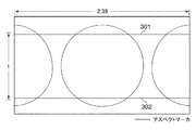
ステップS208において、通常のレンズにより取得された映像(以下「通常の映像」という)に対して、不揮発性メモリ56に格納された2.39:1のアスペクトマーカが重畳表示されるよう、表示部28に指示し、本処理を終了する。これにより、図3に示すように、表示部28は通常の映像と2.39:1(撮影範囲であるシネスコープサイズ)のアスペクト比を示すアスペクトマーカ301,302を表示する。
In step S208, the display unit is configured so that the 2.39:1 aspect marker stored in the
一方、ステップS207において、取得された情報が、アスペクトマーカ表示を無しとする情報である場合は、通常の映像のみが表示されるよう、表示部28に指示し、本処理を終了する(ステップS221)。これにより、図4に示すように、表示部28は通常の映像のみを表示する。 On the other hand, in step S207, when the acquired information is the information indicating that the aspect marker is not displayed, the display unit 28 is instructed to display only the normal image, and the present process ends (step S221). ). As a result, as shown in FIG. 4, the display unit 28 displays only normal video.
ステップS209において、不揮発性メモリ56に登録される映像の切り替えに関する設定を取得する。この設定は、図9のメニュー画面のメニュー設定値906,907の一つが事前にユーザにより選択されることにより不揮発性メモリ56に登録される。この取得した設定に基づき、映像を装着レンズである×2.0アナモフィックレンズで縮めた映像をカメラ側で水平断面に2.0倍に引き伸ばして表示するか、引き伸ばすことなくそのまま表示するかを判別する。具体的には、不揮発性メモリ56にメニュー設定値907が登録されていた場合、装着レンズである×2.0アナモフィックレンズで縮めた映像をカメラ側で引き伸ばして表示すると判断し(ステップS209でYES)、ステップS210に進む。一方、不揮発性メモリ56にメニュー設定値906が登録されていた場合(ステップS209でNO)、装着レンズである×2.0アナモフィックレンズで縮めた映像をカメラ側でそのまま表示すると判断し、ステップS213に進む。
In step S209, the setting relating to the video switching registered in the
ステップS210において、システム制御部50が映像を引き伸ばすよう、画像処理部24に指示をし、画像処理部24で映像を引き伸ばす処理を行う。処理が完了すれば、ステップS211に進む。
In step S210, the
ステップS211において、不揮発性メモリ56に登録されている設定に基づき、アスペクトマーカを映像に重畳表示するか否かを判別する。具体的には、不揮発性メモリ56にメニュー設定値909が登録されていた場合、アスペクトマーカ表示を有りと判断し(ステップS211でYES)、ステップS212に進む。尚、この設定は、図9のメニュー画面のメニュー設定値909,910の一つが事前にユーザにより選択されることにより不揮発性メモリ56に登録される。
In step S211, based on the setting registered in the
ステップS212において、水平断面に2.0倍に引き伸ばした映像に対する、不揮発性メモリ56に格納されたシネスコープサイズのアスペクト比2.39:1のアスペクトマーカの情報を取得し、表示部28にアスペクトマーカの表示を指示する。その後、本処理を終了する。これにより、図5に示すように、表示部28は映像に2.39:1(シネスコープサイズ)のアスペクト比を示すアスペクトマーカ501,502を重畳する。尚、ここで表示部28に表示される映像のサイズは、図5に示すように、2.66:1のアスペクト比を有する。
In step S212, the information of the aspect marker of the cinescope size aspect ratio 2.39:1 stored in the
一方、ステップS211において、不揮発性メモリ56にメニュー設定値910が登録されていた場合、アスペクトマーカ表示を無しと判断してステップS222に進む。ステップS222では、図6に示すように2.66;1のアスペクト比を有する映像のみを表示するよう表示部28に指示し、本処理を終了する。
On the other hand, when the
ステップS213において、不揮発性メモリ56に登録されている設定に基づき、アスペクトマーカを映像に重畳表示するか否かを判別する。具体的には、不揮発性メモリ56にメニュー設定値909が登録されていた場合、アスペクトマーカ表示有りと判断し(ステップS213でYES)、ステップS214に進む。尚、この設定は、ステップS211と同様、図9のメニュー画面のメニュー設定値909,910の一つが事前にユーザにより選択されることにより不揮発性メモリ56に登録される。
In step S213, based on the setting registered in the
ステップS214において、引き伸ばすことなく、装着レンズにより水平断面に1/2倍に縮めたそのままの映像に対する、2.39:1のアスペクトマーカの情報を取得し、表示部28にアスペクトマーカの表示を指示し、本処理を終了する。このとき表示部28に表示される画面を図7に示す。具体的には、2.39:1のシネスコープサイズを水平断面に1/2倍に縮めた1.195:1のアスペクト比を有するアスペクトマーカ701,702が映像に重畳される。尚、ここで表示部28に表示される映像には、引き伸ばした後に表示部28に表示される映像の範囲を示す1.33:1のアスペクト比のマーカ703,704が重畳される。
In step S<b>214, the 2.39:1 aspect marker information for the original image that has been reduced by a factor of 2 in the horizontal section by the attached lens is acquired without stretching, and the display unit 28 is instructed to display the aspect marker. Then, this process ends. A screen displayed on the display unit 28 at this time is shown in FIG. Specifically,
一方、ステップS213において、不揮発性メモリ56にメニュー設定値910が登録されていた場合、アスペクトマーカ表示無しと判断してステップS223に進む。ステップS223では、図8に示すように、1.33:1のアスペクト比が表示された映像のみを表示部28に表示するよう指示し、本処理を終了する。
On the other hand, when the
ステップS215において、不揮発性メモリ56に登録される映像の切り替えに関する設定を取得する。この設定は、ステップS209と同様、図9のメニュー画面のメニュー設定値906,907の一つが事前にユーザにより選択されることにより不揮発性メモリ56に登録される。この取得した設定に基づき、映像を装着レンズである×1.3アナモフィックレンズで縮めた映像をカメラ側で水平断面に1.3倍に引き伸ばして表示するか、引き伸ばすことなくそのまま表示するかを判別する。具体的には、不揮発性メモリ56にメニュー設定値907が登録されていた場合、装着レンズである×1.3アナモフィックレンズで縮めた映像をカメラ側で水平断面に引き伸ばして表示すると判断し(ステップS215でYES)、ステップS216に進む。一方、不揮発性メモリ56にメニュー設定値906が登録されていた場合(ステップS215でNO)、装着レンズである×1.3アナモフィックレンズで縮めた映像をカメラ側でそのまま表示すると判断し、ステップS219に進む。
In step S215, the setting relating to the video switching registered in the
ステップS216において、システム制御部50が映像を引き伸ばすよう、画像処理部24に指示をし、画像処理部24で映像を引き伸ばす処理を行う。処理が完了すれば、ステップS217に進む。
In step S216, the
ステップS217において、不揮発性メモリ56に登録されている設定に基づき、アスペクトマーカを映像に重畳表示するか否かを判別する。具体的には、不揮発性メモリ56にメニュー設定値909が登録されていた場合、アスペクトマーカ表示を有りと判断し(ステップS217でYES)、ステップS218に進む。尚、この設定は、ステップS211と同様、図9のメニュー画面のメニュー設定値909,910の一つが事前にユーザにより選択されることにより不揮発性メモリ56に登録される。
In step S217, based on the setting registered in the
ステップS218において、カメラ側で水平断面に1.3倍に引き伸ばした映像に対する、不揮発性メモリ56に格納されたシネスコープサイズを示す2.39:1のアスペクトマーカの情報を取得し、表示部28に表示する。その後、本処理を終了する。
In step S218, the 2.39:1 aspect marker information indicating the cinescope size stored in the
一方、ステップS217において、不揮発性メモリ56にメニュー設定値910が登録されていた場合、アスペクトマーカ表示を無しと判断してステップS224に進む。ステップS224では、映像のみを表示するよう表示部28に指示し、本処理を終了する。
On the other hand, when the
ステップS219において、不揮発性メモリ56に登録されている設定に基づき、アスペクトマーカを映像に重畳表示するか否かを判別する。具体的には、不揮発性メモリ56にメニュー設定値909が登録されていた場合、アスペクトマーカ表示有りと判断し(ステップS219でYES)、ステップS220に進む。尚、この設定は、ステップS211と同様、図9のメニュー画面のメニュー設定値909,910の一つが事前にユーザにより選択されることにより不揮発性メモリ56に登録される。
In step S219, it is determined whether or not the aspect marker is to be superimposed and displayed on the video based on the setting registered in the
ステップS220において、装着レンズにより水平断面に縮めたそのまま映像に対する、不揮発性メモリ56に格納されたシネスコープサイズを示す2.39:1のアスペクトマーカの情報を取得し、表示部28に表示する。その後、本処理を終了する。具体的には、2.39:1のシネスコープサイズを水平断面に1/1.3倍に縮めた1.84:1を示すアスペクト比を映像に重畳させる。
In step S<b>220, the 2.39:1 aspect marker information indicating the cinescope size stored in the
このように、水平方向に縮められた映像に重畳するアスペクトマーカのアスペクト比は、装着レンズの種別に応じた映像を縮める倍率の違いに応じて以下のように制御される。具体的には、装着レンズの種別が、通常のレンズの場合、重畳するアスペクトマーカのアスペクト比はステップS208のように2.39:1に設定される。装着レンズの種別が、×2.0アナモフィックレンズ(水平断面に映像を1/2.0倍に縮めるレンズ)である場合、重畳するアスペクトマーカのアスペクト比はステップS214のように1.195:1に設定される。一方、×1.3アナモフィックレンズ(水平断面に映像を1/1.3倍に縮めるレンズ)である場合、重畳するアスペクトマーカのアスペクト比はステップS220のように1.84:1に設定される。装着レンズの種別が、通常レンズ(水平断面に映像を1/1.0倍にするレンズ)から、×2.0アナモフィックレンズに変わった場合は、映像に重畳するアスペクトマーカのアスペクト比は2.39:1から1.195:1となる。変更前のアスペクトマーカのアスペクト比を用いて変更後のアスペクトマーカのアスペクト比を表現すると{(2.39×1.0/2.0):1}である。また、装着レンズの種別が、×2.0アナモフィックレンズから、×1.3アナモフィックレンズに変わった場合は、映像に重畳するアスペクトマーカのアスペクト比は1.195:1から1.84:1となる。変更前のアスペクトマーカのアスペクト比を用いて変更後のアスペクトマーカのアスペクト比を表現すると、{(1.195×2.0/1.3):1}である。
In this way, the aspect ratio of the aspect marker to be superimposed on the image compressed in the horizontal direction is controlled as follows according to the difference in the magnification for contracting the image according to the type of the mounted lens. Specifically, when the type of the mounted lens is a normal lens, the aspect ratio of the aspect marker to be superimposed is set to 2.39:1 as in step S208. When the type of the mounted lens is a x2.0 anamorphic lens (a lens that reduces the image to 1/2.0 times in the horizontal section), the aspect ratio of the superimposed aspect marker is 1.195:1 as in step S214. Is set to. On the other hand, in the case of a ×1.3 anamorphic lens (a lens that reduces the image to 1/1.3 times in the horizontal section), the aspect ratio of the aspect marker to be superimposed is set to 1.84:1 as in step S220. .. When the type of the mounted lens is changed from a normal lens (a lens that makes the
すなわち、水平断面に映像を1/a倍に縮めるレンズを水平断面に映像を1/b倍に縮めるレンズに変更した場合(a≧1、b≧1、a≠b)、表示されるアスペクトマーカのアスペクト比は、変更前をM:Nとすると、変更後はM’:N(M×a/b)となる。 That is, when the lens for reducing the image in the horizontal section by 1/a times is changed to the lens for reducing the image in the horizontal section by 1/b times (a≧1, b≧1, a≠b), the displayed aspect marker Assuming that the aspect ratio of M is N before the change, the aspect ratio of is M′:N (M×a/b) after the change.
また、表示部28の画面のアスペクト比(2.39:1=m:n)と装着レンズによる映像を縮める倍率(k)に応じて、装着レンズにより縮めた映像に重畳されるアスペクトマーカのアスペクト比をm/k:nに決定する。一方、カメラ側でこの映像を引き伸ばした場合は、その映像に重畳されるアスペクトマーカのアスペクト比をm:nに決定する。 The aspect ratio of the aspect marker to be superimposed on the image reduced by the mounting lens according to the aspect ratio (2.39:1=m:n) of the screen of the display unit 28 and the magnification (k) for reducing the image by the mounting lens. The ratio is determined to be m/k:n. On the other hand, when this image is stretched on the camera side, the aspect ratio of the aspect marker to be superimposed on the image is determined to be m:n.
このように、本実施形態では、例えば、図7の画面例に示すような、×2.0アナモフィックレンズによって映像を縮めたときの撮影範囲である、1.195:1のアスペクトマーカ表示を、取り付けるレンズの種別と、映像の拡縮の選択で実現している。 Thus, in the present embodiment, for example, as shown in the screen example of FIG. 7, the aspect marker display of 1.195:1, which is the shooting range when the image is reduced by the ×2.0 anamorphic lens, is displayed. This is achieved by selecting the type of lens to be attached and the scaling of the image.
このアスペクト比は、これまでの4:3や16:9といった標準とされているアスペクト比と同様に、設定値としてあらかじめカメラ側で保持していてもよい。この場合、×2.0アナモフィックレンズによって映像を縮めたときの撮影範囲として1.195:1不揮発性メモリ56に保存する。また、×1.3アナモフィックレンズによって映像を縮めたときの撮影範囲として1.84:1のアスペクト比を不揮発性メモリ56に保存する。
This aspect ratio may be held in advance on the camera side as a set value, similar to the standard aspect ratios such as 4:3 and 16:9 so far. In this case, it is stored in the 1.195:1
一方、ステップS219において、不揮発性メモリ56にメニュー設定値910が登録されていた場合、アスペクトマーカ表示無しと判断してステップS225に進む。ステップS225では、映像のみを表示するよう表示部28に指示し、本処理を終了する。
On the other hand, if the
図14は、表示部28で表示されるアスペクト比設定の画面を示す図である。上述したメニューボタンを押すことで、アスペクト比設定1401を画面に表示する。 FIG. 14 is a diagram showing a screen for setting the aspect ratio displayed on the display unit 28. By pressing the menu button described above, the aspect ratio setting 1401 is displayed on the screen.
アスペクト比設定1401は、設定可能な複数のアスペクト比設定値1402をリストで示す。 The aspect ratio setting 1401 shows a list of a plurality of settable aspect ratio values 1402.
複数のアスペクト比設定値1402の中には、×2.0のアナモフィックレンズによって水平断面に縮めた映像の撮影範囲のアスペクト比「1.195:1」を示す設定値1403が含まれる。また、×1.3のアナモフィックレンズによって水平断面に縮めた映像の撮影範囲のアスペクト比「1.84:1」を示す設定値1404も含まれる。
The plurality of aspect
カーソル1405は、ユーザによる上述した上下左右の4方向ボタンの操作に応じて、上記複数のアスペクト比設定値1402から一つを選択する太枠である。ユーザは、上下左右ボタンでカーソル1405を移動して設定値を選択した後、SETボタンを押下すると、システム制御部50は不揮発性メモリ56に登録されているアスペクト比設定値の情報を更新する。
The
(第2の実施形態)
第1の実施形態では、撮影範囲を明示するアスペクトマーカが映像の拡縮に応じて変化する点を説明した。本実施形態は、文字情報等重要な映像を配置する範囲を明示するセーフティゾーン、また、映像の構図を決めるため画面を9つに等分するグリッドに関してもアスペクトマーカと同様に映像の拡縮に応じて変化する点を特徴とする。
(Second embodiment)
In the first embodiment, it has been described that the aspect marker that clearly indicates the shooting range changes according to the scaling of the image. In the present embodiment, the safety zone that clearly shows the range in which important images such as character information are arranged, and the grid that divides the screen into nine equal parts to determine the composition of the image responds to the scaling of the image as with the aspect marker. The feature is that it changes with time.
図10は、装着レンズにより水平断面に縮めたそのままの映像に、アスペクトマーカとセーフティゾーンが重畳された図である。具体的には、図10では、図7の画面にさらに1.195:1のアスペクト比のセーフティゾーン1101が重畳される。
FIG. 10 is a diagram in which the aspect marker and the safety zone are superimposed on the image as it is, which is contracted in the horizontal section by the mounting lens. Specifically, in FIG. 10, a
尚、アスペクトマーカが不要の場合は、図8のような映像のみが表示される画面にセーフティゾーン1001を重畳するようにしてもよい。また、装着レンズで縮めた映像を引き延ばした後の映像にセーフティゾーンを重畳する場合は、2.39:1のアスペクト比のセーフティゾーンが重畳される。 When the aspect marker is unnecessary, the safety zone 1001 may be superimposed on the screen on which only the image as shown in FIG. 8 is displayed. Further, when the safety zone is superimposed on the image obtained by stretching the image contracted by the mounting lens, the safety zone having the aspect ratio of 2.39:1 is superimposed.
また、図11は、装着レンズにより水平断面に縮めたそのままの映像に、アスペクトマーカとグリッドが重畳された図である。具体的には、図11では、図7の画面にさらに1.195:1のアスペクト比のグリッド1101,1102,1103,1104が重畳される。
Further, FIG. 11 is a diagram in which the aspect marker and the grid are superimposed on the image as it is, which is contracted in the horizontal section by the mounting lens. Specifically, in FIG. 11,
尚、図10と同様、アスペクトマーカが不要の場合は、図8のような映像のみが表示される画面にグリッド1101,1102,1103,1104を重畳するようにしてもよい。また、装着レンズで縮めた映像を引き延ばした後の映像にグリッドを重畳する場合は、2.39:1のアスペクト比のグリッドが重畳される。
As in the case of FIG. 10, when the aspect marker is not necessary, the
尚、図7,10,11では、アスペクトマーカ、セーフティゾーン、グリッドのいずれかのマーカについて、装着レンズで水平断面に1/k倍に縮めたそのままの映像に対するアスペクト比m/k:nを示すマーカのみが表示部28に表示される。しかしながら、このようなマーカだけでなく、その映像を水平断面に引き伸ばした後の映像(以下「実映像」という)に対するアスペクト比m:nを示すマーカも同時に表示するようにしてもよい。この場合、同時に示すマーカが対応関係にあることがわかるよう、それぞれ同色または同じ線種で表示する。 It should be noted that FIGS. 7, 10, and 11 show the aspect ratio m/k:n for any one of the aspect marker, the safety zone, and the grid with respect to the image as it is, which is reduced by 1/k times in the horizontal section with the mounting lens. Only the marker is displayed on the display unit 28. However, not only such a marker but also a marker indicating an aspect ratio m:n with respect to an image (hereinafter referred to as “actual image”) after the image is stretched to a horizontal section may be displayed at the same time. In this case, the markers that are shown at the same time are displayed in the same color or the same line type so that it can be seen that they have a corresponding relationship.
図12は、図10の画面に、さらに実映像に対するアスペクトマーカ、セーフティゾーンが重畳された状態を示す図である。具体的には、図10の画面に、水平断面に2倍に引き伸ばした後の映像に対するアスペクトマーカ1203,1204や、セーフティゾーン1206,1207が重畳される。
FIG. 12 is a diagram showing a state in which an aspect marker and a safety zone for the actual image are further superimposed on the screen of FIG. Specifically, the
また、図13は、図11の画面にさらに実映像に対するアスペクトマーカ、グリッドが重畳された状態を示す図である。具体的には、図11の画面に、水平断面に2倍に引き伸ばした後の映像に対するグリッド1305,1306,1307,1308が重畳される。
Further, FIG. 13 is a diagram showing a state in which an aspect marker and a grid for the actual image are further superimposed on the screen of FIG. Specifically,
以上、本発明をその好適な実施形態に基づいて詳述してきたが、本発明はこれら特定の実施形態に限られるものではなく、この発明の要旨を逸脱しない範囲の様々な形態も本発明に含まれる。上述の実施形態の一部を適宜組み合わせてもよい。また、上述の実施形態の機能を実現するソフトウェアのプログラムを、記録媒体から直接、或いは有線/無線通信を用いてプログラムを実行可能なコンピュータを有するシステム又は装置に供給し、そのプログラムを実行する場合も本発明に含む。従って、本発明の機能処理をコンピュータで実現するために、該コンピュータに供給、インストールされるプログラムコード自体も本発明を実現するものである。つまり、本発明の機能処理を実現するためのコンピュータプログラム自体も本発明に含まれる。その場合、プログラムの機能を有していれば、オブジェクトコード、インタプリタにより実行されるプログラム、OSに供給するスクリプトデータ等、プログラムの形態を問わない。プログラムを供給するための記録媒体としては、例えば、ハードディスク、磁気テープ等の磁気記録媒体、光/光磁気記憶媒体、不揮発性の半導体メモリでもよい。また、プログラムの供給方法としては、コンピュータネットワーク上のサーバに本発明を形成するコンピュータプログラムを記憶し、接続のあったクライアントコンピュータがコンピュータプログラムをダウンロードしてプログラムするような方法も考えられる。 Although the present invention has been described in detail above based on its preferred embodiments, the present invention is not limited to these specific embodiments, and various embodiments within the scope not departing from the gist of the present invention are also included in the present invention. included. Part of the above-described embodiments may be combined as appropriate. Further, in the case where a software program that realizes the functions of the above-described embodiments is supplied from a recording medium directly or by using wired/wireless communication to a system or apparatus having a computer that can execute the program and the program is executed. Also included in the present invention. Therefore, the program code itself supplied to and installed in the computer to implement the functional processing of the present invention by the computer also implements the present invention. That is, the computer program itself for realizing the functional processing of the present invention is also included in the present invention. In that case, the program may take any form such as an object code, a program executed by an interpreter, or script data supplied to an OS as long as it has the function of the program. The recording medium for supplying the program may be, for example, a hard disk, a magnetic recording medium such as a magnetic tape, an optical/magneto-optical storage medium, or a non-volatile semiconductor memory. Further, as a method of supplying the program, a method of storing the computer program forming the present invention in a server on a computer network and allowing a connected client computer to download and program the computer program can be considered.
22 撮像部
24 画像処理部
28 表示部
32 メモリ
50 システム制御部
56 不揮発性メモリ
70 操作部
100 ビデオカメラ
103 レンズ
150 レンズユニット
22
Claims (17)
前記レンズ装着部に装着されたレンズの種別を判別する判別手段と、
前記判別手段で、前記レンズ装着部に装着されたレンズの種別が垂直方向に対して水平方向に映像を1/a(a≧1)倍にする第1のレンズであると判別された場合は、前記第1のレンズを介して取得した第1の映像に重畳してアスペクト比がM:Nの第1のアスペクトマーカを表示し、前記判別手段で、前記レンズ装着部に装着されたレンズの種別が垂直方向に対して水平方向に前記映像を1/b(b≧1、a≠b)倍にする第2のレンズであると判別された場合は、前記第2のレンズを介して取得した第2の映像に重畳してアスペクト比がM’:N(M’=M×a/b)の第2のアスペクトマーカを表示するよう制御する表示制御手段と
を備えることを特徴とする撮像装置。 A lens mount,
Discriminating means for discriminating the type of the lens mounted on the lens mounting portion;
When the determining unit determines that the type of the lens mounted on the lens mounting unit is the first lens that makes the image 1/a (a≧1) times in the horizontal direction with respect to the vertical direction, , A first aspect marker having an aspect ratio of M:N is displayed so as to be superimposed on the first image acquired through the first lens, and the discriminating unit displays the first aspect marker of the lens attached to the lens attaching section. When it is determined that the type is the second lens that makes the image 1/b (b≧1, a≠b) times in the horizontal direction with respect to the vertical direction, the image is acquired through the second lens. And a display control means for controlling to display a second aspect marker having an aspect ratio of M′:N (M′=M×a/b) so as to be superimposed on the second image. apparatus.
前記表示制御手段は、前記第1の変形映像を表示する場合に、アスペクト比がm:nのアスペクトマーカを表示するように制御し、前記第2の変形映像を表示する場合に、アスペクト比がm:nのアスペクトマーカを表示するように制御することを特徴とする請求項1記載の撮像装置。 Further comprising a deforming unit for generating a first modified image in which the first image is horizontally stretched a times and a second modified image in which the second image is horizontally stretched b times.
The display control means controls to display an aspect marker having an aspect ratio of m:n when displaying the first modified image, and displays an aspect ratio when displaying the second modified image. The image pickup apparatus according to claim 1, wherein the aspect marker of m:n is controlled to be displayed.
前記第1のレンズを介して取得した第1の映像を水平方向にa倍に引き伸ばした第1の変形映像を生成する変形手段と、
映像を表示する表示手段と、
前記第1の変形映像を表示する場合、アスペクト比がm:nの第1のアスペクトマーカを前記第1の変形映像に重畳して表示し、前記第1の映像を表示する場合、アスペクト比がm/a:nの第2のアスペクトマーカを前記第1の映像に重畳して表示するように制御する表示制御手段と
を備えることを特徴とする撮像装置。 A lens mounting portion capable of mounting a first lens that shrinks an image by 1/a times (a>1) in the horizontal direction with respect to the vertical direction;
Deforming means for generating a first deformed image by horizontally stretching the first image acquired through the first lens by a times;
Display means for displaying images,
When the first modified image is displayed, a first aspect marker having an aspect ratio of m:n is superimposed and displayed on the first modified image, and when the first image is displayed, the aspect ratio is and a display control unit that controls the second aspect marker of m/a:n to be displayed so as to be superimposed on the first image.
前記変形手段は、前記第2のレンズを介して取得した第2の映像を水平方向にb倍に引き伸ばした第2の変形映像を更に生成し、
前記表示制御手段は、前記第2の変形映像を表示する場合、アスペクト比がm:nの第1のアスペクトマーカを前記第2の変形映像に重畳して表示するように制御することを特徴とする請求項5記載の撮像装置。 The lens mounting portion can mount a second lens that shrinks an image by 1/b times in the horizontal direction with respect to the vertical direction (b>1, a≠b),
The deforming means further generates a second deformed image obtained by horizontally stretching the second image acquired through the second lens by b times,
The display control means controls, when displaying the second modified image, a first aspect marker having an aspect ratio of m:n so as to be superimposed and displayed on the second modified image. The image pickup apparatus according to claim 5.
前記レンズ装着部に装着されたレンズの種別を判別する判別ステップと、
前記判別ステップにおいて、前記レンズ装着部に装着されたレンズの種別が垂直方向に対して水平方向に映像を1/a(a≧1)倍にする第1のレンズであると判別された場合は、前記第1のレンズを介して取得した第1の映像に重畳してアスペクト比がM:Nの第1のアスペクトマーカを表示し、前記判別ステップにおいて、前記レンズ装着部に装着されたレンズの種別が垂直方向に対して水平方向に前記映像を1/b(b≧1、a≠b)倍にする第2のレンズであると判別された場合は、前記第2のレンズを介して取得した第2の映像に重畳してアスペクト比がM’:N(M’=M×a/b)の第2のアスペクトマーカを表示するよう制御する表示制御ステップと、
を有することを特徴とする表示制御方法。 A display control method for displaying an image acquired through a lens mounted on the lens mounting section, the display control method being executed in an imaging device including a lens mounting section,
A determination step of determining the type of the lens attached to the lens attachment portion,
When it is determined in the determination step that the type of the lens mounted on the lens mounting portion is the first lens that makes the image 1/a (a≧1) times in the horizontal direction with respect to the vertical direction, , A first aspect marker having an aspect ratio of M:N is displayed by being superimposed on the first image acquired via the first lens, and in the determining step, the first aspect marker of the lens attached to the lens attachment section is displayed. When it is determined that the type is the second lens that makes the image 1/b (b≧1, a≠b) times in the horizontal direction with respect to the vertical direction, the image is acquired through the second lens. A display control step of controlling to display a second aspect marker having an aspect ratio of M′:N (M′=M×a/b), which is superimposed on the second image.
A display control method comprising:
前記第1の映像を水平方向にa倍に引き伸ばした第1の変形映像を生成する変形ステップと、
前記第1の変形映像を表示する場合、アスペクト比がm:nの第1のアスペクトマーカを前記第1の変形映像に重畳して表示し、前記第1の映像を表示する場合、アスペクト比がm/a:nの第2のアスペクトマーカを前記第1の映像に重畳して表示するように制御する表示制御ステップと、
を有することを特徴とする表示制御方法。 A first image acquired via the first lens, which is executed in an image pickup apparatus equipped with a first lens that shrinks the image 1/a times (a>1) in the horizontal direction with respect to the vertical direction. A display control method for displaying
A deforming step of generating a first deformed image by stretching the first image horizontally by a times;
When the first modified image is displayed, a first aspect marker having an aspect ratio of m:n is superimposed and displayed on the first modified image, and when the first image is displayed, the aspect ratio is a display control step of controlling so as to superimpose and display a second aspect marker of m/a:n on the first image;
A display control method comprising:
Priority Applications (2)
| Application Number | Priority Date | Filing Date | Title |
|---|---|---|---|
| JP2016215403A JP6746468B2 (en) | 2016-11-02 | 2016-11-02 | IMAGING DEVICE, DISPLAY CONTROL METHOD THEREOF, AND PROGRAM |
| US15/796,899 US10313595B2 (en) | 2016-11-02 | 2017-10-30 | Image pickup apparatus that displays aspect markers, and storage medium |
Applications Claiming Priority (1)
| Application Number | Priority Date | Filing Date | Title |
|---|---|---|---|
| JP2016215403A JP6746468B2 (en) | 2016-11-02 | 2016-11-02 | IMAGING DEVICE, DISPLAY CONTROL METHOD THEREOF, AND PROGRAM |
Publications (3)
| Publication Number | Publication Date |
|---|---|
| JP2018074514A JP2018074514A (en) | 2018-05-10 |
| JP2018074514A5 JP2018074514A5 (en) | 2019-11-21 |
| JP6746468B2 true JP6746468B2 (en) | 2020-08-26 |
Family
ID=62022835
Family Applications (1)
| Application Number | Title | Priority Date | Filing Date |
|---|---|---|---|
| JP2016215403A Active JP6746468B2 (en) | 2016-11-02 | 2016-11-02 | IMAGING DEVICE, DISPLAY CONTROL METHOD THEREOF, AND PROGRAM |
Country Status (2)
| Country | Link |
|---|---|
| US (1) | US10313595B2 (en) |
| JP (1) | JP6746468B2 (en) |
Families Citing this family (2)
| Publication number | Priority date | Publication date | Assignee | Title |
|---|---|---|---|---|
| JP7057139B2 (en) * | 2018-01-16 | 2022-04-19 | キヤノン株式会社 | Image pickup device, control method of image pickup device, program and recording medium |
| WO2020044844A1 (en) * | 2018-08-29 | 2020-03-05 | ソニー株式会社 | Signal processing device, signal processing method, signal processing program, and image capture device |
Family Cites Families (17)
| Publication number | Priority date | Publication date | Assignee | Title |
|---|---|---|---|---|
| JP2810160B2 (en) * | 1989-11-10 | 1998-10-15 | 株式会社日立製作所 | Camera device and camera recording system |
| JPH0364170A (en) * | 1989-08-02 | 1991-03-19 | Hitachi Ltd | Camera equipment and camera video recording system |
| EP0411440A3 (en) * | 1989-08-02 | 1992-01-29 | Hitachi, Ltd. | Camera system and camera recording system |
| DE69226302T2 (en) * | 1991-04-25 | 1999-02-11 | Canon Kk | Image overlay system for different aspect ratios |
| JP3091628B2 (en) * | 1994-03-30 | 2000-09-25 | 三洋電機株式会社 | Stereoscopic video camera |
| US5598205A (en) * | 1994-04-22 | 1997-01-28 | Olympus Optical Co., Ltd. | Imaging apparatus |
| JPH1070675A (en) | 1996-08-26 | 1998-03-10 | Sony Corp | Valid area display method and display device for view finder of video camera having aspect ratio conversion function |
| US20020140711A1 (en) * | 2001-03-28 | 2002-10-03 | Alps Electric Co., Ltd. | Image display device for displaying aspect ratios |
| TWI228378B (en) * | 2003-06-19 | 2005-02-21 | Primax Electronics Ltd | Auxiliary method and device for finding view |
| US20050166249A1 (en) * | 2004-01-26 | 2005-07-28 | Wiatt Kettle | Fitting video feed to a display device |
| JP3982533B2 (en) * | 2004-11-04 | 2007-09-26 | ソニー株式会社 | Imaging device and method for controlling use of photographing auxiliary mark |
| JP4655135B2 (en) * | 2008-10-22 | 2011-03-23 | ソニー株式会社 | Imaging apparatus, imaging area display method, and imaging area display program |
| JP4715913B2 (en) * | 2008-12-17 | 2011-07-06 | ソニー株式会社 | Imaging apparatus, image processing apparatus, zoom control method, and zoom control program |
| JP2010226185A (en) * | 2009-03-19 | 2010-10-07 | Olympus Imaging Corp | Imaging apparatus, and method of controlling imaging apparatus |
| JP5451259B2 (en) * | 2009-08-28 | 2014-03-26 | キヤノン株式会社 | Imaging apparatus, control method thereof, and program |
| JP6460868B2 (en) * | 2015-03-19 | 2019-01-30 | キヤノン株式会社 | Display control apparatus and control method thereof |
| JP6727989B2 (en) * | 2016-08-31 | 2020-07-22 | キヤノン株式会社 | Image processing apparatus and control method thereof |
-
2016
- 2016-11-02 JP JP2016215403A patent/JP6746468B2/en active Active
-
2017
- 2017-10-30 US US15/796,899 patent/US10313595B2/en active Active
Also Published As
| Publication number | Publication date |
|---|---|
| US10313595B2 (en) | 2019-06-04 |
| US20180124324A1 (en) | 2018-05-03 |
| JP2018074514A (en) | 2018-05-10 |
Similar Documents
| Publication | Publication Date | Title |
|---|---|---|
| JP4288612B2 (en) | Image processing apparatus and method, and program | |
| KR100868773B1 (en) | Image pickup apparatus having a help function, method for controlling the same, and recording medium | |
| US9819857B2 (en) | Electronic apparatus, control method for the same, and image capturing apparatus | |
| JP5782813B2 (en) | Imaging apparatus and image display method | |
| US9066008B2 (en) | Display control apparatus and method for controlling the same | |
| US20230089239A1 (en) | Image processing apparatus, image pickup apparatus, image processing method, and storage medium | |
| JP2017103520A (en) | Image processing apparatus, control method of image processing apparatus, and program | |
| US10388035B2 (en) | Image processing apparatus, image processing method, and storage medium | |
| US11245846B2 (en) | Image capturing control apparatus and control method therefor | |
| JP6746468B2 (en) | IMAGING DEVICE, DISPLAY CONTROL METHOD THEREOF, AND PROGRAM | |
| JP2021021857A (en) | Imaging apparatus and control method thereof | |
| JP6403473B2 (en) | Imaging apparatus, control method thereof, and program | |
| JP6768449B2 (en) | Imaging control device, control method and program of imaging device | |
| KR101812656B1 (en) | Digital photographing apparatus and control method thereof | |
| JP6758843B2 (en) | Shooting control device and its control method | |
| JP6184077B2 (en) | Imaging device and control method thereof. | |
| US20190394368A1 (en) | Image capturing apparatus, control method thereof, and non-transitory computer-readable storage medium | |
| JP2010074415A (en) | Imaging apparatus, image display method and image display program | |
| JP6362645B2 (en) | IMAGING DEVICE, ITS CONTROL METHOD, PROGRAM, AND STORAGE MEDIUM | |
| JP6210795B2 (en) | Display control apparatus and control method thereof | |
| JP2015159357A (en) | Image processing system, image processing method, and program | |
| JP2020191599A (en) | Imaging apparatus and control method of the same | |
| JP2018186461A (en) | Electronic apparatus, control method for electronic apparatus, program, and, recording medium | |
| JP2017085430A (en) | Imaging apparatus | |
| JP2016082269A (en) | Imaging apparatus |
Legal Events
| Date | Code | Title | Description |
|---|---|---|---|
| A521 | Request for written amendment filed |
Free format text: JAPANESE INTERMEDIATE CODE: A523 Effective date: 20191010 |
|
| A621 | Written request for application examination |
Free format text: JAPANESE INTERMEDIATE CODE: A621 Effective date: 20191010 |
|
| A977 | Report on retrieval |
Free format text: JAPANESE INTERMEDIATE CODE: A971007 Effective date: 20200423 |
|
| A131 | Notification of reasons for refusal |
Free format text: JAPANESE INTERMEDIATE CODE: A131 Effective date: 20200526 |
|
| A521 | Request for written amendment filed |
Free format text: JAPANESE INTERMEDIATE CODE: A523 Effective date: 20200623 |
|
| TRDD | Decision of grant or rejection written | ||
| A01 | Written decision to grant a patent or to grant a registration (utility model) |
Free format text: JAPANESE INTERMEDIATE CODE: A01 Effective date: 20200707 |
|
| A61 | First payment of annual fees (during grant procedure) |
Free format text: JAPANESE INTERMEDIATE CODE: A61 Effective date: 20200805 |
|
| R151 | Written notification of patent or utility model registration |
Ref document number: 6746468 Country of ref document: JP Free format text: JAPANESE INTERMEDIATE CODE: R151 |