JP6743343B2 - Electronically controllable pneumatic braking system for commercial vehicles and electronic control method for pneumatic braking system of commercial vehicles - Google Patents
Electronically controllable pneumatic braking system for commercial vehicles and electronic control method for pneumatic braking system of commercial vehicles Download PDFInfo
- Publication number
- JP6743343B2 JP6743343B2 JP2019503730A JP2019503730A JP6743343B2 JP 6743343 B2 JP6743343 B2 JP 6743343B2 JP 2019503730 A JP2019503730 A JP 2019503730A JP 2019503730 A JP2019503730 A JP 2019503730A JP 6743343 B2 JP6743343 B2 JP 6743343B2
- Authority
- JP
- Japan
- Prior art keywords
- valve
- bypass
- pressure
- brake
- switching position
- Prior art date
- Legal status (The legal status is an assumption and is not a legal conclusion. Google has not performed a legal analysis and makes no representation as to the accuracy of the status listed.)
- Active
Links
Images


Classifications
-
- B—PERFORMING OPERATIONS; TRANSPORTING
- B60—VEHICLES IN GENERAL
- B60T—VEHICLE BRAKE CONTROL SYSTEMS OR PARTS THEREOF; BRAKE CONTROL SYSTEMS OR PARTS THEREOF, IN GENERAL; ARRANGEMENT OF BRAKING ELEMENTS ON VEHICLES IN GENERAL; PORTABLE DEVICES FOR PREVENTING UNWANTED MOVEMENT OF VEHICLES; VEHICLE MODIFICATIONS TO FACILITATE COOLING OF BRAKES
- B60T13/00—Transmitting braking action from initiating means to ultimate brake actuator with power assistance or drive; Brake systems incorporating such transmitting means, e.g. air-pressure brake systems
- B60T13/10—Transmitting braking action from initiating means to ultimate brake actuator with power assistance or drive; Brake systems incorporating such transmitting means, e.g. air-pressure brake systems with fluid assistance, drive, or release
- B60T13/66—Electrical control in fluid-pressure brake systems
- B60T13/68—Electrical control in fluid-pressure brake systems by electrically-controlled valves
- B60T13/683—Electrical control in fluid-pressure brake systems by electrically-controlled valves in pneumatic systems or parts thereof
-
- B—PERFORMING OPERATIONS; TRANSPORTING
- B60—VEHICLES IN GENERAL
- B60T—VEHICLE BRAKE CONTROL SYSTEMS OR PARTS THEREOF; BRAKE CONTROL SYSTEMS OR PARTS THEREOF, IN GENERAL; ARRANGEMENT OF BRAKING ELEMENTS ON VEHICLES IN GENERAL; PORTABLE DEVICES FOR PREVENTING UNWANTED MOVEMENT OF VEHICLES; VEHICLE MODIFICATIONS TO FACILITATE COOLING OF BRAKES
- B60T13/00—Transmitting braking action from initiating means to ultimate brake actuator with power assistance or drive; Brake systems incorporating such transmitting means, e.g. air-pressure brake systems
- B60T13/10—Transmitting braking action from initiating means to ultimate brake actuator with power assistance or drive; Brake systems incorporating such transmitting means, e.g. air-pressure brake systems with fluid assistance, drive, or release
- B60T13/58—Combined or convertible systems
- B60T13/585—Combined or convertible systems comprising friction brakes and retarders
- B60T13/586—Combined or convertible systems comprising friction brakes and retarders the retarders being of the electric type
-
- B—PERFORMING OPERATIONS; TRANSPORTING
- B60—VEHICLES IN GENERAL
- B60T—VEHICLE BRAKE CONTROL SYSTEMS OR PARTS THEREOF; BRAKE CONTROL SYSTEMS OR PARTS THEREOF, IN GENERAL; ARRANGEMENT OF BRAKING ELEMENTS ON VEHICLES IN GENERAL; PORTABLE DEVICES FOR PREVENTING UNWANTED MOVEMENT OF VEHICLES; VEHICLE MODIFICATIONS TO FACILITATE COOLING OF BRAKES
- B60T15/00—Construction arrangement, or operation of valves incorporated in power brake systems and not covered by groups B60T11/00 or B60T13/00
- B60T15/02—Application and release valves
- B60T15/025—Electrically controlled valves
- B60T15/027—Electrically controlled valves in pneumatic systems
-
- B—PERFORMING OPERATIONS; TRANSPORTING
- B60—VEHICLES IN GENERAL
- B60T—VEHICLE BRAKE CONTROL SYSTEMS OR PARTS THEREOF; BRAKE CONTROL SYSTEMS OR PARTS THEREOF, IN GENERAL; ARRANGEMENT OF BRAKING ELEMENTS ON VEHICLES IN GENERAL; PORTABLE DEVICES FOR PREVENTING UNWANTED MOVEMENT OF VEHICLES; VEHICLE MODIFICATIONS TO FACILITATE COOLING OF BRAKES
- B60T15/00—Construction arrangement, or operation of valves incorporated in power brake systems and not covered by groups B60T11/00 or B60T13/00
- B60T15/02—Application and release valves
- B60T15/04—Driver's valves
- B60T15/043—Driver's valves controlling service pressure brakes
-
- B—PERFORMING OPERATIONS; TRANSPORTING
- B60—VEHICLES IN GENERAL
- B60T—VEHICLE BRAKE CONTROL SYSTEMS OR PARTS THEREOF; BRAKE CONTROL SYSTEMS OR PARTS THEREOF, IN GENERAL; ARRANGEMENT OF BRAKING ELEMENTS ON VEHICLES IN GENERAL; PORTABLE DEVICES FOR PREVENTING UNWANTED MOVEMENT OF VEHICLES; VEHICLE MODIFICATIONS TO FACILITATE COOLING OF BRAKES
- B60T17/00—Component parts, details, or accessories of power brake systems not covered by groups B60T8/00, B60T13/00 or B60T15/00, or presenting other characteristic features
- B60T17/18—Safety devices; Monitoring
- B60T17/22—Devices for monitoring or checking brake systems; Signal devices
- B60T17/226—Devices for monitoring or checking brake systems; Signal devices using devices being responsive to the difference between the fluid pressions in conduits of multiple braking systems
- B60T17/227—With additional functions, e.g. by-pass
-
- B—PERFORMING OPERATIONS; TRANSPORTING
- B60—VEHICLES IN GENERAL
- B60T—VEHICLE BRAKE CONTROL SYSTEMS OR PARTS THEREOF; BRAKE CONTROL SYSTEMS OR PARTS THEREOF, IN GENERAL; ARRANGEMENT OF BRAKING ELEMENTS ON VEHICLES IN GENERAL; PORTABLE DEVICES FOR PREVENTING UNWANTED MOVEMENT OF VEHICLES; VEHICLE MODIFICATIONS TO FACILITATE COOLING OF BRAKES
- B60T7/00—Brake-action initiating means
- B60T7/02—Brake-action initiating means for personal initiation
- B60T7/04—Brake-action initiating means for personal initiation foot actuated
- B60T7/06—Disposition of pedal
-
- B—PERFORMING OPERATIONS; TRANSPORTING
- B60—VEHICLES IN GENERAL
- B60T—VEHICLE BRAKE CONTROL SYSTEMS OR PARTS THEREOF; BRAKE CONTROL SYSTEMS OR PARTS THEREOF, IN GENERAL; ARRANGEMENT OF BRAKING ELEMENTS ON VEHICLES IN GENERAL; PORTABLE DEVICES FOR PREVENTING UNWANTED MOVEMENT OF VEHICLES; VEHICLE MODIFICATIONS TO FACILITATE COOLING OF BRAKES
- B60T7/00—Brake-action initiating means
- B60T7/02—Brake-action initiating means for personal initiation
- B60T7/04—Brake-action initiating means for personal initiation foot actuated
Landscapes
- Engineering & Computer Science (AREA)
- Transportation (AREA)
- Mechanical Engineering (AREA)
- Braking Systems And Boosters (AREA)
- Regulating Braking Force (AREA)
- Valves And Accessory Devices For Braking Systems (AREA)
Description
本発明は、商用車の電子的に制御可能な空気圧式制動システムと商用車の空気圧式制動システムを電子的に制御する方法に関する。 The present invention relates to an electronically controllable pneumatic braking system for a commercial vehicle and a method for electronically controlling a pneumatic braking system for a commercial vehicle.
空気圧式制動システムを備えた車両、特に、商用車では、ブレーキ圧を制御するために、車両軸に割り当てられたアクスルモデュレータを制御機器(ECU)により電子的に駆動することができる。その場合、電子的な駆動は、フットブレーキバルブにより与えられる運転者の要求に応じて、さもなければ自動的に与えられる車両目標減速に応じて行なわれる。そして、アクスルモデュレータは、制動システムの常用ブレーキのブレーキシリンダに対して制御される相応の常用ブレーキ・ブレーキ圧を空気圧により発生させている。 In vehicles equipped with a pneumatic braking system, especially commercial vehicles, an axle modulator assigned to the vehicle axle can be electronically driven by a control unit (ECU) in order to control the brake pressure. In that case, the electronic drive takes place in response to the driver's request, which is provided by the footbrake valve, or in response to a vehicle target deceleration which is otherwise provided automatically. Then, the axle modulator pneumatically generates a corresponding service brake/brake pressure controlled for the brake cylinder of the service brake of the braking system.
それに代わって、フットブレーキバルブにより、アクスルモデュレータに対する運転者の要求に応じた常用ブレーキ制御圧を与え、その圧力に応じて、各アクスルモデュレータが空気流量増幅部により常用ブレーキのための相応の常用ブレーキ・ブレーキ圧を発生させることによって、空気圧によってもアクスルモデュレータを駆動することができる。ABS機能が両方の変化形態に統合されており、その結果、制動時の車輪のロックを防止することができる。 Instead, the foot brake valve provides a service brake control pressure corresponding to the driver's request for the axle modulator, and each axle modulator is controlled by the air flow rate amplification unit for service brake according to the pressure. By generating a corresponding service brake pressure, it is also possible to drive the axle modulator by air pressure. The ABS function is integrated in both variants, so that the locking of the wheels during braking can be prevented.
そのような制動システムにおいて、例えば、運転者が不注意であるか、或いは現状に合わない緊急状況で自動的に介入できる自動的に駆動可能なフォールバックモード又は冗長性を実現するための複数の解決策も知られている。それらの解決策では、制動の段階的な付与も規定されているので、そのような解決策は、大抵は多数の追加の空気圧部品を必要とする。例えば、パーキングブレーキの電子空気圧式駆動により、電気による冗長な駆動を可能にする負担のかかる別の解決策も知られている。そのような全ての解決策の欠点は、追加の空気圧部品が取付負担とコスト負担を上昇させ、更に、非常に面倒な形でしか追加装備できないことである。 In such braking systems, for example, a plurality of automatically actuatable fallback modes or redundancies for the driver to automatically intervene in an inadvertent or out-of-the-box emergency situation are provided. Solutions are also known. Such solutions often also require a large number of additional pneumatic components, since they also define the gradual application of braking. Another burdensome solution is known, which enables redundant drive by electricity, for example by electropneumatic drive of the parking brake. The disadvantage of all such solutions is that the additional pneumatic components add mounting and cost burdens and, moreover, can only be added in a very cumbersome manner.
特許文献1は、そのためのカーブ支援制動システムを記載しており、そこには、電子制御式マルチポートバルブを用いて制動システムの常用ブレーキに対する常用ブレーキ・ブレーキ圧を制御し、ブレーキ値供給器としてのフットブレーキバルブからの制動要求が無い場合でも常用ブレーキ・ブレーキ圧を制御することが規定されている。そのマルチポートバルブとフットブレーキバルブは、切換バルブ(ハイセレクトバルブ)によって、常用ブレーキに対する常用ブレーキ・ブレーキ圧を制御するリレーバルブの方に切り換えられている。その場合、切換バルブは、フットブレーキバルブとマルチポートバルブの二つの圧力の中の高い方だけをリレーバルブに伝え、その結果、マルチポートバルブの電子的な制動要求がフットブレーキバルブによりオーバーコントロールされてしまう可能性が有る。 Patent Document 1 describes a curve assisted braking system therefor, in which an electronically controlled multi-port valve is used to control a service brake/brake pressure for a service brake of a braking system, and as a brake value supply device. It is regulated to control the service brake/brake pressure even when there is no braking request from the foot brake valve. The multi-port valve and the foot brake valve are switched by a switching valve (high select valve) to a relay valve that controls the service brake/brake pressure for the service brake. In that case, the diverter valve transfers only the higher of the two pressures of the footbrake valve and the multiport valve to the relay valve, so that the electronic braking demand of the multiport valve is overcontrolled by the footbrake valve. There is a possibility that it will end up.
特許文献2又は特許文献3は、フットブレーキバルブ又はブレーキペダル機器からの制動要求を与えられる制動設備を記載している。その要求は、制御機器において、電子信号に変換され、その電子信号を用いて、常用ブレーキに対する常用ブレーキ・ブレーキ圧を制御するアクスルモデュレータを駆動している。電子機器が故障すると、冗長的な場合に、アクスルモデュレータが、圧縮空気配管を介して常用ブレーキ・制御圧を用いて空気圧により駆動され、更に、常用ブレーキに対する常用ブレーキ・ブレーキ圧が出力されている。アクスルモデュレータは、そのために電磁バルブとリレーバルブを備えている。その電磁バルブの位置に応じて、フットブレーキバルブにより与えられる作動圧力か、圧力媒体貯蔵部からの貯蔵圧力か、或いは排気部からの大気圧が常用ブレーキ・制御圧として使用されている。それによって、手動的又は電気的な付与に基づく三つの電磁バルブの電子的に与えられる切換位置に応じて、常用ブレーキ・ブレーキ圧を上昇、維持又は低下させることができる。
特許文献4は、フットブレーキバルブを備えた電子空気圧式常用ブレーキ装置を記載しており、そのブレーキペダル位置は検知することができ、そのアクスルモデュレータを駆動するために出力される作動圧力はブレーキペダル位置に関係なく修正することができる。そのために、例えば、電子的な要求に応じてフットブレーキ入力圧力をフットブレーキバルブに導入するための二つの3/2ポートバルブを備えた電磁バルブ機器が配備されている。追加のホールディングバルブによって、作用するフットブレーキ入力圧力が保持されている。そのフットブレーキ入力圧力の作用によって、コントロールピストンが、フットブレーキバルブ内を空気圧により機械的に動かされ、その結果、フットブレーキバルブによって、その空気圧による操作に対応して作動圧力が制御され、その作動圧力が、常用ブレーキ・制御圧としてアクスルモデュレータに更に伝えられる。それによって、冗長的な場合に、即ち、常用ブレーキの電気による駆動が失敗した場合で、かつ運転者による手動の操作が存在しない場合に、フットブレーキバルブとその空気圧通路によって、制動を実行することができる。そのため、フットブレーキバルブの電子制御の擬似的な機械空気圧式操作が得られている。 Patent Document 4 describes an electropneumatic service brake device equipped with a foot brake valve, the position of the brake pedal of which can be detected, and the working pressure output to drive the axle modulator is It can be corrected regardless of the brake pedal position. To that end, for example, electromagnetic valve devices have been provided with two 3/2 port valves for introducing footbrake input pressure to the footbrake valve in response to electronic demand. An additional holding valve holds the applied footbrake input pressure. Due to the action of the footbrake input pressure, the control piston is mechanically moved by air pressure in the footbrake valve, so that the footbrake valve controls the working pressure in response to the pneumatic operation, The pressure is further transmitted to the axle modulator as service brake/control pressure. Thereby, in a redundant case, i.e. when the electric drive of the service brake fails and when there is no manual operation by the driver, braking is performed by the foot brake valve and its pneumatic passage. You can Therefore, an electronically controlled pseudo mechanical pneumatic operation of the foot brake valve has been obtained.
フットブレーキバルブの別の機械的な操作が、例えば、特許文献5及び6に記載されている。そこには、電子制御機器によって、ブレーキペダルに加えて、フットブレーキバルブを操作する方法が、それぞれ記載されている。それによると、フットブレーキバルブと追加のリレーバルブにより常用ブレーキを駆動する電子制動システムが規定されている。一方において、ブレーキペダルによって、さもなければ、それと独立して、ブレーキペダルとフットブレーキバルブの間に配置されたブレーキバルブ・アクチュエータによって、その制動要件をフットブレーキバルブに与えることができる。車両を制動するための制御信号が存在する場合に、例えば、空気圧バルブとして実現されたブレーキバルブ・アクチュエータに対する制御圧が制御され、その結果、フットブレーキバルブが操作されることによって、そのブレーキバルブ・アクチュエータは電子制御機器により制御されている。 Another mechanical actuation of the footbrake valve is described, for example, in US Pat. There, respectively, a method for operating a foot brake valve in addition to a brake pedal by an electronic control device is described. It defines an electronic braking system that drives a service brake with a foot brake valve and an additional relay valve. On the one hand, the braking requirements can be applied to the footbrake valve by a brake pedal which is arranged between the brake pedal and the footbrake valve or otherwise independently of it. In the presence of a control signal for braking the vehicle, for example, the control pressure for a brake valve actuator, which is realized as a pneumatic valve, is controlled and, as a result, the foot brake valve is actuated so that the brake valve The actuator is controlled by an electronic control device.
特許文献7には、フットブレーキバルブが、ポートバルブを介して空気圧により常用ブレーキと接続された制動装置が記載されている。そのポートバルブの第一の切換位置では、手動操作によりフットブレーキバルブが発生する作動圧力が、常用ブレーキに直に出力される。第二の切換位置では、逆止めバルブがフットブレーキバルブと常用ブレーキの間を切り換えている。その逆止めバルブは、フットブレーキバルブにより実現される常用ブレーキに対する圧力上昇を可能にするが、常用ブレーキの圧力低下又は排気を防止し、そのため、上昇した常用ブレーキ・ブレーキ圧を維持する役割を果たしている。
特許文献8には、2/2ポートバルブとして実現された二つのと少なくとも一つのハイセレクトバルブとを備えた制動システムが記載されている。それらの2/2ポートバルブは、圧力媒体貯蔵部から流れ込む、貯蔵圧力を有する圧力媒体又は排気部をハイセレクトバルブと直接接続するように、測定された常用ブレーキ・制御圧に応じて電子的に切り換えることができる。それによって、常用ブレーキ・ブレーキ圧の電気制御による圧力上昇又は圧力低下を実現することができる。2/2ポートバルブの相応の切換位置によって、常用ブレーキ・制御圧を維持することもできる。それに加えて、運転者がフットブレーキバルブの操作により与える作動圧力もハイセレクトバルブに案内されている。その際、ハイセレクトバルブは、常用ブレーキに加えられる二つの圧力の中の高い方、即ち、相応のバイパスバルブから提供される貯蔵部・入力圧力又はフットブレーキ・入力圧力か、或いは作動圧力を制御している。そのため、手動による運転者操作が存在しない場合に、二つの2/2ポートバルブと一つのハイセレクトバルブを用いて、電子的に制御された形で圧力上昇、圧力維持又は圧力低下を実現することができる。
特許文献9は、双安定3/2ポートバルブと単安定3/2ポートバルブを備えた運転者支援システムを記載している。その双安定3/2ポートバルブの相応の切換位置において、アクスルモデュレータの空気圧制御入力に、プレッシャーリザーバーの圧力低下のために圧力媒体貯蔵部を接続するか、或いはプレッシャーリザーバーの圧力上昇のために排気部を接続することによって、双安定3/2ポートバルブにより、駐車ブレーキのプレッシャーリザーバーを充填又は排気することができる。双安定3/2ポートバルブとアクスルモデュレータの間には、一方の切換位置で双安定3/2ポートバルブから出力されるパーキングブレーキ・制御圧をアクスルモデュレータに通過させ、それ以外の切換位置でフロー接続を阻止する単安定3/2ポートバルブが配置されている。即ち、単安定3/2ポートバルブの第二の切換位置では、アクスルモデュレータに対して優勢なパーキングブレーキ・制御圧が維持されている。 US Pat. No. 6,037,049 describes a driver assistance system with a bistable 3/2 port valve and a monostable 3/2 port valve. In the corresponding switching position of the bistable 3/2-port valve, the pneumatic control input of the axle modulator is connected to a pressure medium reservoir for pressure reduction of the pressure reservoir or for pressure increase of the pressure reservoir. The bistable 3/2 port valve allows the pressure reservoir of the parking brake to be filled or evacuated by connecting the exhaust to. Between the bistable 3/2-port valve and the axle modulator, the parking brake/control pressure output from the bistable 3/2-port valve is passed to the axle modulator at one switching position, and A monostable 3/2 port valve is located that blocks the flow connection in the switching position. That is, in the second switching position of the monostable 3/2-port valve, the parking brake/control pressure that is dominant with respect to the axle modulator is maintained.
本発明の課題は、特に、自動制御車両において、電子的に制御される安全で確実な冗長制動を少ない負担で保証することができる、商用車の電子的に制御可能な空気圧式制動システムを提供することである。更に、本発明の課題は、商用車のそのような制動システムを電子的に制御する方法を提示することである。 An object of the present invention is to provide an electronically controllable pneumatic braking system for a commercial vehicle, which is capable of guaranteeing electronically controlled safe and reliable redundant braking with a small burden, particularly in an automatically controlled vehicle. It is to be. Furthermore, the object of the invention is to present a method for electronically controlling such a braking system of a commercial vehicle.
この課題は、請求項1に記載の電子的に制御可能な空気圧式制動システムと請求項15に記載の方法によって解決される。有利な改善構成は従属請求項に記載されている。
This problem is solved by an electronically controllable pneumatic braking system according to claim 1 and a method according to
そのために、本発明では、フットブレーキバルブにより与えられる、電子的に制御可能な空気圧式制動システムの少なくとも一つのアクスルモデュレータを駆動する常用ブレーキ・制御圧が、フットブレーキバルブの排気空間内に導入される、フットブレーキバルブ入力圧を有する圧力媒体に応じて生成することができると規定される。この場合、特に、冗長な場合に、有利には、常用ブレーキ・制御圧は、フットブレーキバルブのコントロールピストンの手動により、或いは自動的に引き起こされる動きに応じて与えられない。 To this end, the invention provides that the service brake/control pressure provided by the foot brake valve, which drives at least one axle modulator of the electronically controllable pneumatic braking system, is in the exhaust space of the foot brake valve. It is defined that it can be generated in response to the introduced pressure medium having the foot brake valve input pressure. In this case, in particular in the case of redundancy, advantageously no service brake and control pressure is applied either manually or in response to an automatically triggered movement of the control piston of the foot brake valve.
特に、冗長な場合には、むしろ、与えられたフットブレーキ入力圧力を有する圧力媒体が、有利には、フットブレーキバルブのフットブレーキ排気ポートに導入され、その結果、フットブレーキバルブが操作されない場合に、そのため、コントロールピストンが操作されない場合に、その圧力媒体が、排気空間と作動空間を介して、フットブレーキバルブの一つ又は複数の制御ポートに流入することができる。これらの制御ポートは、それぞれ一つのブレーキ回路に割り当てられた少なくとも一つのアクスルモデュレータの空気圧フォールバックモードのための空気圧制御入力と接続されており、その結果、アクスルモデュレータの空気圧制御入力には、ほぼフットブレーキ入力圧力が常用ブレーキ・制御圧として加わる。この場合、例えば、圧力損失は、フットブレーキバルブの貫流により起こり得る。この常用ブレーキ・制御圧は、各アクスルモデュレータにより空気流量を増幅されて、車両の車輪ブレーキ又は常用ブレーキに圧力を加えるための常用ブレーキ・ブレーキ圧として出力され、その結果、車両は、それぞれ駆動された常用ブレーキによって制動することができる。 In particular, in the redundant case, rather, a pressure medium with a given footbrake input pressure is advantageously introduced into the footbrake exhaust port of the footbrake valve, so that the footbrake valve is not operated. Therefore, when the control piston is not operated, the pressure medium can flow into the one or more control ports of the foot brake valve via the exhaust space and the working space. These control ports are connected to a pneumatic control input for the pneumatic fallback mode of at least one axle modulator, which is assigned to one braking circuit respectively, and as a result, the pneumatic control input of the axle modulator. Is applied with the foot brake input pressure as the regular brake/control pressure. In this case, for example, pressure loss can occur due to the flow through the footbrake valve. This service brake/control pressure is output as service brake/brake pressure for applying pressure to the vehicle wheel brakes or service brakes by amplifying the air flow rate by each axle modulator, and as a result, the vehicle is respectively It can be braked by a serviced brake that is driven.
それに代わって、相応のブレーキ回路のアクスルモデュレータが省かれて、フットブレーキバルブにより制御される常用ブレーキ・制御圧が、車両の常用ブレーキに対する常用ブレーキ・ブレーキ圧として直接制御されると規定することもできる。それは、例えば、常用ブレーキを相応に操作するためには、アクスルモデュレータによる空気流量の増幅が最早必要でないように、フットブレーキ入力圧力又は常用ブレーキ・制御圧が既に設計されている場合に実施することができる。 Instead, the axle modulator of the corresponding brake circuit is omitted, and the service brake/control pressure controlled by the foot brake valve is directly controlled as the service brake/brake pressure for the service brake of the vehicle. You can also This is done, for example, if the footbrake input pressure or the service brake/control pressure is already designed so that amplification of the air flow by the axle modulator is no longer required for the service brake to operate properly. can do.
従って、有利には、排気空間内に導入される、フットブレーキ入力圧力を有する圧力媒体によって、フットブレーキバルブの機械的な操作は実行されない。この場合、フットブレーキバルブの機械的な操作とは、フットブレーキバルブのコントロールピストンの任意の(手動により、或いは自動的に要求されて、例えば、電気、機械又は空気圧により引き起こされる)動きであると理解される。この場合、コントロールピストンとは、操作機器、例えば、ブレーキペダルの操作時に、その機械的な操作を、操作に応じて、圧力媒体貯蔵部から作動空間を介したフットブレーキバルブの制御ポートへの圧力媒体の貫流に変換する、フットブレーキバルブのピストンである。そのため、それは、制動システムの任意の圧力媒体貯蔵部からアクスルモデュレータ又は車輪ブレーキに圧力媒体を段階的に開放する役割を果たし、そのために、例えば、作動空間内の別のピストン、例えば、リレーピストンやステップピストンに作用を及ぼすものである。そのために、コントロールピストン自体は、作動空間自体の中には配置されず、場合によっては、その境界を画定する。従って、作動空間内に流入する圧力媒体は、場合によっては、コントロールピストンの負荷を軽減するように作用する。 Therefore, advantageously, no mechanical actuation of the footbrake valve is carried out by the pressure medium having a footbrake input pressure introduced into the exhaust space. In this case, the mechanical actuation of the footbrake valve is any movement of the control piston of the footbrake valve (manually or automatically required and caused, for example, electrically, mechanically or pneumatically). To be understood. In this case, the control piston means a mechanical operation of an operating device, for example, a brake pedal, when operating the pressure medium from the pressure medium reservoir to the control port of the foot brake valve through the working space. It is the piston of the footbrake valve that transforms it into the medium flow. As such, it serves to gradually release the pressure medium from any pressure medium reservoir of the braking system to the axle modulator or the wheel brakes, for which purpose, for example, another piston in the working space, for example a relay It acts on the piston and step piston. As a result, the control piston itself is not arranged in the working space itself, but in some cases defines its boundary. The pressure medium flowing into the working space thus acts in some cases to reduce the load on the control piston.
そのため、本発明では、簡単な手法で事前に確認されたフットブレーキ入力圧力を直に常用ブレーキ・制御圧としてアクスルモデュレータに通過させ、その際、フットブレーキ入力圧力に依存すること無く(例えば、追加の気密な制御空間を介して)、コントロールピストンに作用させて、それを機械的に操作又は移動し、それによって、作動空間内に有る圧力媒体のフロー挙動に影響を与えるために、既にフットブレーキバルブに存在するインタフェース(排気空間又はフットブレーキ・排気ポート)が使用される。 Therefore, in the present invention, the foot brake input pressure confirmed in advance by a simple method is directly passed through the axle modulator as the regular brake/control pressure, and at that time, without depending on the foot brake input pressure (for example, , Via an additional airtight control space) to actuate or mechanically operate or move the control piston, thereby affecting the flow behavior of the pressure medium in the working space, The interface (exhaust space or foot brake/exhaust port) present in the foot brake valve is used.
それによって、冗長性を実現するために、有利には、例えば、気密な制御空間を提供するために、通常の動作に影響を与える可能性が有るか、或いは不必要に大きな負担を必要とする既存の空気圧配管又はフットブレーキバルブ自体を変更することが不要となる。そのため、組立負担及び信頼性を改善することができる。更に、排気までの既存の空気圧式制動システムに変更を加える必要が無くなるので、簡単に追加配備する手法が得られる。 Thereby, in order to achieve redundancy, which may advantageously affect normal operation, for example to provide a tight control space, or requires an unnecessarily high burden. It is not necessary to change the existing pneumatic piping or the foot brake valve itself. Therefore, the assembly burden and reliability can be improved. In addition, there is no need to make changes to the existing pneumatic braking system up to exhaust, thus providing a simple additional deployment approach.
本発明では、冗長な場合に、常用ブレーキ・制御圧を与えるフットブレーキ入力圧力の付与は、一つの実施構成において、電気制御可能な3/2ポートバルブとして実現される第一のバイパスバルブ構成により行なわれる。この3/2ポートバルブの第一の切換位置では、フットブレーキバルブの排気空間が、例えば、バイパス排気部と接続されることによって、低い圧力レベルが与えられ、第二の切換位置では、例えば、バイパス圧力媒体貯蔵部が排気空間と接続されることによって、高い圧力レベルが与えられる。そのため、第一の切換位置では、排気空間を排気することができ、その結果、その中では、ほぼ大気圧が優勢となり、第二の切換位置では、バイパス圧力媒体貯蔵部からの圧力媒体が、3/2ポートバルブとフットブレーキ排気ポートを介して、フットブレーキバルブの排気空間内に流入することによって、排気空間内において、バイパス圧力媒体貯蔵部内で優勢なバイパス貯蔵圧力、例えば、8バールを設定することができる。この場合、バイパス圧力媒体貯蔵部は、例えば、商用車のパーキングブレーキ・ブレーキ回路用の圧力媒体貯蔵部であるとするか、さもなければ、商用車内の追加の別個の圧力媒体貯蔵部であるとすることもできる。 In the present invention, in the redundant case, the application of the foot brake input pressure for providing the normal brake/control pressure is achieved by the first bypass valve configuration realized as an electrically controllable 3/2 port valve in one embodiment. Done. In the first switching position of the 3/2-port valve, the exhaust space of the foot brake valve is provided with a low pressure level, for example, by being connected to a bypass exhaust part, and in the second switching position, for example, By connecting the bypass pressure medium reservoir with the exhaust space, a high pressure level is provided. Therefore, in the first switching position, the exhaust space can be exhausted, and as a result, the atmospheric pressure is predominant therein, and in the second switching position, the pressure medium from the bypass pressure medium storage section is By entering into the exhaust space of the footbrake valve via the 3/2 port valve and the footbrake exhaust port, the bypass pressure prevailing in the bypass pressure medium reservoir is set in the exhaust space, for example 8 bar. can do. In this case, the bypass pressure medium reservoir may be, for example, a pressure medium reservoir for a parking brake/brake circuit of a commercial vehicle, or else an additional separate pressure medium reservoir in a commercial vehicle. You can also do it.
別の実施構成では、代替の第二のバイパスバルブ構成が、それぞれ開閉することができる二つの電気制御可能な2/2ポートバルブを有する。第一の2/2ポートバルブは、低い圧力レベルを与えるためにバイパス排気部と接続され、第二の2/2ポートバルブは、高い圧力レベルを与えるためにバイパス圧力媒体貯蔵部と接続されており、二つの2/2ポートバルブは、排気空間又はフットブレーキ排気ポートに合流する。第一の2/2ポートバルブが開かれ、第二の2/2ポートバルブが閉じられている場合(二つの2/2ポートバルブに関する第一の切換位置)、バイパス排気部は、フットブレーキバルブの排気空間とフローに関して接続される。それに対して、第一の2/2ポートバルブが閉じられ、第二の2/2ポートバルブが開かれている場合(二つの2/2ポートバルブに関する第二の切換位置)、バイパス圧力媒体貯蔵部は、フットブレーキバルブの排気空間とフローに関して接続される。そのため、この実施構成でも、大気圧に一致するか、或いはバイパス貯蔵圧力に一致するフットブレーキ入力圧力を与えることができ、その圧力は、排気空間と作動空間を介して、相応の常用ブレーキ・制御圧を設定する。 In another implementation, an alternative second bypass valve configuration has two electrically controllable 2/2 port valves that can each be opened and closed. The first 2/2 port valve is connected to the bypass exhaust to provide a low pressure level, and the second 2/2 port valve is connected to the bypass pressure medium reservoir to provide a high pressure level. The two 2/2-port valves join the exhaust space or the foot brake exhaust port. If the first 2/2-port valve is open and the second 2/2-port valve is closed (first switching position for the two 2/2-port valves), the bypass exhaust will be a foot brake valve. Connected with the exhaust space of the flow. By contrast, if the first 2/2-port valve is closed and the second 2/2-port valve is opened (second switching position for the two 2/2-port valves), bypass pressure medium storage The parts are connected in flow with the exhaust space of the footbrake valve. Therefore, in this embodiment as well, it is possible to provide a footbrake input pressure that corresponds to the atmospheric pressure or to the bypass storage pressure, which pressure, through the exhaust space and the working space, corresponds to the corresponding service brake/control. Set the pressure.
それに追加して、この第二のバイパスバルブ構成においても、圧力センサーにより、例えば、フットブレーキ排気ポートに出力されるフットブレーキ入力圧力を測定し、それに応じて、第一又は第二の2/2ポートバルブを開閉して、フットブレーキ入力圧力を上方及び下方に調整することによって、フットブレーキ入力圧力を制御することができる。この実施形態では、それに追加して、二つの2/2ポートバルブを閉じることによって、フットブレーキ入力圧力を維持することもできる。 In addition to this, also in this second bypass valve configuration, the pressure sensor measures, for example, the footbrake input pressure output to the footbrake exhaust port and, accordingly, the first or second 2/2. The footbrake input pressure can be controlled by opening and closing the port valve to adjust the footbrake input pressure up and down. In addition to this, in this embodiment, the footbrake input pressure can also be maintained by closing two 2/2 port valves.
第一と第二のバイパスバルブ構成は、冗長な場合、即ち、制動システムの常用ブレーキ制御機器(ECU)によるアクスルモデュレータの電気駆動の障害時であって、かつ制動が必要であり、運転者がその制動自体を許容しないことが確認された場合に、それぞれバイパス制御機器(バイパスECU)からのバイパス信号により電子的に駆動される。そのため、冗長な場合に、各バイパスバルブ構成の第二の切換位置によって、フットブレーキ入力圧力への常用ブレーキ・制御圧の電子空気圧方式により制御された上昇を実行することができ、その結果、各アクスルモデュレータにより、それに対応する高い、有利には、最大限に常用ブレーキを操作する常用ブレーキ・ブレーキ圧が生成される。各バイパスバルブ構成の第一の切換位置では、電子空気圧方式により制御された排気も、そのため、常用ブレーキ・制御圧又は常用ブレーキ・ブレーキ圧の低下も実行することができる。 The first and second bypass valve configurations are redundant, i.e. when there is a failure in the electrical drive of the axle modulator by the service brake control equipment (ECU) of the braking system and braking is required When it is confirmed that the person does not allow the braking itself, the vehicle is electronically driven by a bypass signal from each bypass control device (bypass ECU). Therefore, in a redundant case, the second switching position of each bypass valve configuration allows an electronically pneumatically controlled rise of the service brake/control pressure to the footbrake input pressure, which results in each The axle modulator produces a correspondingly high, advantageously service brake braking pressure, which maximizes service braking. In the first switching position of each bypass valve arrangement, exhaust controlled by electropneumatics and thus also a reduction of the service brake/control pressure or the service brake/brake pressure can be carried out.
従って、各バイパスバルブ構成の相応の切換位置によって、常用ブレーキの電子空気圧方式により制御された完全な閉鎖又は完全な開放を簡単な手法で実現することができる。それによると、本発明では、車両、特に、自動制御可能な商用車において、各アクスルモデュレータによる車両の常用ブレーキの電気駆動の障害時に、それにより通常の動作に影響を与えること無く、車両を安全に制動された状態に、特に、停車状態に単に移行させる結果となる。これは、有利には、単に一つの追加の3/2ポートバルブ又は二つの2/2ポートバルブと、冗長な場合に、高いフットブレーキ入力圧力の電子空気圧式付与に変換できる役割を果たす相応の駆動論理部とによって実現することができる。この場合、追加のバイパスバルブ構成は、手動による操作に影響を与えないと同時に、冗長な場合以外に安全な排気を可能にする役割を果たす。 Therefore, the corresponding switching positions of the respective bypass valve configurations make it possible in a simple manner to achieve a fully closed or fully opened, pneumatically controlled closing of the service brake. According to this, in the present invention, in a vehicle, in particular, in an automatically controllable commercial vehicle, when the electric drive of the service brake of the vehicle by each axle modulator fails, the vehicle operation is not affected thereby without affecting normal operation. Will result in a simple transition of the vehicle to a safely braked state, in particular to a stopped state. This advantageously serves only one additional 3/2-port valve or two 2/2-port valves and, in the redundant case, can be converted into an electro-pneumatic application of high footbrake input pressure. And the driving logic. In this case, the additional bypass valve arrangement does not affect the manual operation and at the same time serves to allow safe venting except in the case of redundancy.
従って、そのような電子空気圧方式による冗長性を実現するために、有利には、高価なバルブ、例えば、段階的に制動する役割を果たす、複数のソレノイドバルブ、或いはフットブレーキバルブ又はバイパス圧力媒体貯蔵部からの圧力を通過させるハイセレクトバルブが不要となる。そのため、本発明では、耐用期間中の車両における常用ブレーキの電気による自動駆動の全体的な障害の確率が非常に小さくなり、従って、特に、相応のバルブを切り換える時の騒音の発生、圧力媒体の消費及び車輪ブレーキの磨耗に関して最適な解決策が必ずしも必要でないことが分かる。これらの全ての観点は、車両の安全で冗長的な制動に作用を及ぼさず、その結果、そのような特別な例外的な場合に対して考慮する必要がないか、或いはコストを削減するために、その不利な作用を我慢することができる。 Therefore, in order to realize such electro-pneumatic redundancy, it is advantageous to use expensive valves, for example a plurality of solenoid valves, or a foot brake valve or a bypass pressure medium storage, which act in a stepwise braking manner. It eliminates the need for a high select valve that allows pressure from the section to pass through. As a result, according to the invention, the probability of an overall failure of the automatic electric drive of the service brake in a vehicle during its service life is very low, and therefore, in particular when switching the corresponding valves, the generation of noise, pressure medium It can be seen that an optimal solution for consumption and wheel brake wear is not always necessary. All these aspects have no effect on the safe and redundant braking of the vehicle, so that there is no need to consider for such special exceptional cases, or to reduce costs. , You can put up with its adverse effects.
フットブレーキバルブは、冗長な場合に、フットブレーキバルブの操作による純粋に機械的な(運転者によって手動により、或いは自動的に制御された)付与に依存するか、或いはフットブレーキバルブが操作されない時のバイパスバルブ構成により与えられるフットブレーキ入力圧力に依存する常用ブレーキ・制御圧を出力することができる。しかし、フットブレーキバルブが操作された場合、それにより引き起こされるピストン位置は、有利には、排気空間又は作動空間からのフットブレーキ入力圧力を有する圧力媒体がフットブレーキバルブの制御ポートに到達することを阻止する。そのため、フットブレーキバルブが手動により、或いは自動的に制御される形で純粋に機械的に操作された場合に、電子空気圧式付与の実行が阻止される。 The footbrake valve relies on purely mechanical (manually or automatically controlled by the driver) actuation of the footbrake valve in the redundant case or when the footbrake valve is not operated. It is possible to output the service brake/control pressure that depends on the foot brake input pressure provided by the bypass valve configuration of. However, when the footbrake valve is operated, the piston position caused thereby advantageously causes a pressure medium having a footbrake input pressure from the exhaust space or the working space to reach the control port of the footbrake valve. Stop. This prevents the electropneumatic application from being carried out if the footbrake valve is operated purely mechanically in a manually or automatically controlled manner.
有利には、バイパスバルブ構成は単安定である、即ち、排気空間が排気される、バイパスバルブ構成の第一の切換位置だけが安定している。この場合、「安定している」とは、バイパスバルブ構成を電気的に駆動しない場合、即ち、電流を流さない場合に、安定した(第一の)切換位置に自動的に設定されることであると理解する。それは、例えば、一つの3/2ポートバルブ又は二つの2/2ポートバルブの相応のバネによる付勢によって実現することができる。それによって、バイパスバルブ構成が第一の切換位置に自動的に復帰するので、通常の動作において、冗長な場合以外でも、エネルギー供給部の障害時に、排気を確実に実行できることを保証できる。 Advantageously, the bypass valve arrangement is monostable, i.e. only the first switching position of the bypass valve arrangement in which the exhaust space is evacuated is stable. In this case, "stable" is automatically set to a stable (first) switching position when the bypass valve configuration is not electrically driven, that is, when no current flows. Understand that there is. It can be realized, for example, by biasing one 3/2-port valve or two 2/2-port valves with corresponding springs. As a result, the bypass valve structure is automatically returned to the first switching position, so that it is possible to ensure that the exhaust can be surely executed when the energy supply unit fails in a normal operation, even when it is not redundant.
この場合、安定な第一の切換位置は、標準的には、冗長的な場合でも運転者が依然として制動形態で介入可能であることから出発できる場合に設定される。それに対して、安定でない第二の切換位置は、冗長的な場合に、例えば、運転者が現状に合わないか、或いは不注意であるために、フットブレーキバルブが操作されないことが確認された場合に設定される。この場合、第二の切換位置は、例えば、持続的に電流を流すことにより連続して設定することができ、その結果、常用ブレーキが持続的に作動される。 In this case, the stable first switching position is normally set when the driver can start from the fact that he can still intervene in braking mode, even in the case of redundancy. On the other hand, the unstable second switching position is redundant, for example, when it is confirmed that the foot brake valve is not operated because the driver does not fit the current situation or is careless. Is set to. In this case, the second switching position can be set continuously, for example by continuously applying a current, so that the service brake is continuously activated.
有利な改善構成では、第一のバイパスバルブ構成によって、電子空気圧方式により制御された形で常用ブレーキ・制御圧又は常用ブレーキ・ブレーキ圧の段階的な設定を実現することもできる。そのために、バイパスバルブ構成は、バイパス制御機器によって、例えば、パルス形態により駆動することができる、即ち、第一のバイパスバルブ構成又は3/2ポートバルブは、電流を流されることと、電流を流されないことを交互に繰り返される。この場合、有利には、バイパス信号がパルス幅変調された形で与えられる。それによって、第一と第二の切換位置の間を交互に往復して切り換えられ、その結果、フットブレーキ入力圧力が、設定される第一と第二の切換位置の時間長に応じて、場合によっては、圧力を調整されたバイパス貯蔵圧力と、バイパス排気部内の大気圧との間を往復して変動する、即ち、二つの圧力に応じて与えられる。従って、フットブレーキバルブから出力される常用ブレーキ・制御圧の脈動する推移が得られる。その結果、更に、各アクスルモデュレータにより制御された、同様に脈動する常用ブレーキ・ブレーキ圧が得られ、それは、常用ブレーキによって、相応の手法により制動に変換される。 In an advantageous refinement, the first bypass valve arrangement also makes it possible to realize a stepwise setting of the service brake/control pressure or the service brake/brake pressure in a controlled manner by means of an electronic pneumatic system. To that end, the bypass valve arrangement can be driven by the bypass control device, for example in pulsed form, ie the first bypass valve arrangement or the 3/2 port valve is energized and energized. What is not done is repeated alternately. In this case, the bypass signal is preferably provided in pulse-width modulated form. As a result, the first and second switching positions are alternately reciprocated and switched, so that the foot brake input pressure varies depending on the time length of the first and second switching positions to be set. In some cases, the pressure fluctuates back and forth between the regulated bypass storage pressure and the atmospheric pressure in the bypass exhaust, i.e., it is provided according to two pressures. Therefore, a pulsating transition of the service brake/control pressure output from the foot brake valve can be obtained. The result is also a similarly pulsating service brake pressure controlled by each axle modulator, which is converted by the service brake into braking in a corresponding manner.
第二のバイパスバルブ構成においても、例えば、フットブレーキ入力圧力を測定する圧力センサーが存在せず、そのため、圧力制御が不可能である場合に、二つの2/2ポートバルブをパルス幅変調形態により駆動することによって、この方式によるフットブレーキ入力圧力の段階的な付与を実施することができる。 Even in the second bypass valve configuration, for example, when there is no pressure sensor that measures the footbrake input pressure, and therefore pressure control is not possible, two 2/2 port valves are configured by pulse width modulation. By driving, stepwise application of the foot brake input pressure by this method can be performed.
有利には、それによって、車両に強い制動と弱い制動を交互に加える一種の間欠制動を実現することができる。これは、車両の走行安定性と操舵可能性に有利に作用することができ、なぜなら、冗長的な場合に、即ち、電子的な障害時に、車両内に有るABS機能によるブレーキスリップ制御が正しく機能することが保証されないからである。この例外的な場合に、この制御を間欠制動機能により置き換えることができる。この間欠制動は、有利には、パルス幅変調による駆動時に、ロックする傾向に有る車輪の回復を実行できることを保証することにより実現できる。それは、例えば、フットブレーキ入力圧力又は常用ブレーキ・ブレーキ圧が少なくとも、例えば、0.25秒の限界時間の間、例えば、1バールの限界圧力を下回る場合である。この場合、ロックする傾向に有る車輪が再び回転できることが保証される。 Advantageously, this makes it possible to realize a type of intermittent braking, in which a strong braking and a weak braking are applied alternately to the vehicle. This can have an advantageous effect on the driving stability and steerability of the vehicle, because in a redundant case, i.e. during an electronic fault, the brake slip control by means of the ABS function in the vehicle will work correctly. It is not guaranteed to do. In this exceptional case, this control can be replaced by an intermittent braking function. This intermittent braking can advantageously be realized by ensuring that a recovery of the wheel, which tends to lock, can be carried out when driving with pulse width modulation. That is the case, for example, when the footbrake input pressure or the service brake braking pressure is at least below a limiting pressure of, for example, 1 bar for a limiting time of, for example, 0.25 seconds. In this case it is ensured that the wheels, which tend to lock up, can rotate again.
それによって、追加の構成部品を用いた冗長なABS機能を節約することもできる。この場合でも、同じく安全に制動する役割を果たすことができる簡単な置換機能を実現することによって、電気的な障害の例外的な場合に対するコストを制約できることが分かる。 It can also save redundant ABS functionality with additional components. Even in this case, it can be seen that the cost for exceptional cases of electrical faults can be constrained by implementing a simple replacement function that can also serve the role of safe braking.
この場合、パルス形態の駆動により実現される切換挙動は、間欠制動時において、車両減速、走行安定性及び操舵可能性に関して受け入れ可能な値が設定されるように設計される。 In this case, the switching behavior realized by driving in pulse form is designed such that acceptable values are set for vehicle deceleration, running stability and steerability during intermittent braking.
この場合、通過する管路とバルブは、一種のローパスフィルターの役割を果たし、二つの切換位置の間を往復して切り換えられた場合にフットブレーキ入力圧力を、そのため、常用ブレーキ・制御圧も、より小さく上下させる機能を有する。そのため、フットブレーキ入力圧力の変動する推移のエッジは、より小さく上昇するか、或いはより小さく低下し、その結果、特に、フットブレーキ入力圧力が第二の切換位置でバイパス貯蔵圧力に到達する前に、再び第一の切換位置に切り換わる、即ち、その推移が全体として滑らかになる。 In this case, the passage and the valve passing through play a role of a kind of low-pass filter, and the foot brake input pressure when switching back and forth between the two switching positions, and therefore the service brake/control pressure, It has a function to make it smaller and smaller. As a result, the edges of the fluctuating transition of the footbrake input pressure rise smaller or fall smaller, so that, in particular, before the footbrake input pressure reaches the bypass storage pressure in the second switching position. , The state is switched to the first switching position again, that is, the transition becomes smooth as a whole.
有利な改善構成に基づき、バイパス貯蔵圧力の圧力適合によって、そのため、フットブレーキ入力圧力の圧力適合によっても、この滑らかさを更に最適化することができ、その結果、バイパスバルブ構成の第二の切換位置に切り換えた場合に、常用ブレーキ・制御圧が非常に高い圧力に上昇することが防止される。そのために、それに代わって、或いはそれに追加して規定することができる複数の変化形態が実現可能である。 Due to the advantageous refinement, the pressure adaptation of the bypass storage pressure and thus also the pressure adaptation of the footbrake input pressure makes it possible to further optimize this smoothness, so that a second switching of the bypass valve arrangement is achieved. When switched to the position, the service brake/control pressure is prevented from rising to a very high pressure. To that end, several variants can be realized which can be defined instead of or in addition to it.
最も簡単な実施構成では、第二の切換位置でフットブレーキ入力圧力を付与するバイパス圧力媒体貯蔵部とバイパスバルブ構成との間に絞り弁が配置される。この絞り弁は、バイパス圧力媒体貯蔵部から流出する圧力媒体の体積流量を低減する。それによって、絞り弁により流路内に括れ部が形成されるので、第一の切換位置から第二の切換位置に切り換えた場合に、フットブレーキ入力圧力がバイパス貯蔵圧力にまで急激に上昇するのではなく、ゆっくりと上昇する。即ち、第一の切換位置に戻す切り換えが、フットブレーキ入力圧力がより小さく上昇する時点で行なわれ、その結果、その推移が全体として一層滑らかになる。 In the simplest implementation, a throttle valve is arranged between the bypass pressure medium reservoir for applying the footbrake input pressure in the second switching position and the bypass valve arrangement. The throttle valve reduces the volumetric flow of pressure medium flowing out of the bypass pressure medium reservoir. As a result, the throttle valve forms a constricted portion in the flow path, so that when the first switching position is switched to the second switching position, the foot brake input pressure rapidly rises to the bypass storage pressure. Rather slowly rising. That is, the switching back to the first switching position is performed when the footbrake input pressure rises to a smaller extent, and as a result, the transition becomes smoother as a whole.
別の実施構成では、より低いバイパス貯蔵圧力が優勢であるバイパス圧力媒体貯蔵部を当初から使用すると規定することができる。そのために、例えば、パーキングブレーキのために配備された、最大8バールの貯蔵圧力を有する圧力媒体貯蔵部を使用することができる。 In another implementation, it may be provided that the bypass pressure medium reservoir, where the lower bypass storage pressure predominates, is initially used. To that end, it is possible to use, for example, a pressure medium reservoir with a storage pressure of up to 8 bar, which is provided for parking brakes.
別の実施構成では、バイパス圧力媒体貯蔵部からの所定の限界圧力までの圧力媒体だけを通過させる減圧器を構成部品として組み込むこともできる。 In another embodiment, a pressure reducer that passes only the pressure medium from the bypass pressure medium reservoir up to a predetermined limit pressure may be incorporated as a component.
全ての場合において、この制御されるバイパス貯蔵圧力の圧力を制限するか、或いは体積流量を制限することによって、更に、バイパスバルブ構成が予想外に第二の切換位置に切り換えられた場合に、それにより意図しない形で要求される車両減速の制限も実現することができる。 In all cases, by limiting the pressure of this controlled bypass storage pressure or limiting the volumetric flow rate, it is further provided that the bypass valve configuration is unexpectedly switched to the second switching position. As a result, the limitation of vehicle deceleration that is unintentionally required can be realized.
有利な改善構成では、バイパス制御機器は、所定の車両軸の常用ブレーキ・制御圧が加わる圧力センサー又は圧力スイッチによって、運転者がフットブレーキバルブを操作したのか否かを確認することができる。操作された場合、圧力スイッチ又は圧力センサーが、相応の信号をバイパス制御機器に出力する。それによって、冗長的な場合に、運転者が対処したのかを確認して、場合によっては、電気による冗長な駆動をバイパスバルブ構成により停止することができる。更に、それにより導き出される運転者要求に関する妥当性確認によって、潜在的な誤りを検知することができる。 In an advantageous refinement, the bypass control device can determine whether the driver has actuated the footbrake valve by means of a pressure sensor or pressure switch to which the service brake/control pressure of a given vehicle axle is applied. When actuated, the pressure switch or pressure sensor outputs a corresponding signal to the bypass control device. Thereby, in a redundant case, it is possible to confirm whether the driver has dealt with, and in some cases, the redundant electric drive can be stopped by the bypass valve configuration. In addition, the validation with respect to the driver demands thereby derived makes it possible to detect potential errors.
有利には、バイパス制御機器(バイパスECU)が、第一のエネルギー源と、それに加えて、それと独立した第二のエネルギー源とからエネルギーを供給され、制動システムの常用ブレーキ制御機器(ECU)が、第一のエネルギー源からのみエネルギーを供給され、その結果、常用ブレーキ制御機器(ECU)による電気的な駆動の障害時において、それにも関わらず、電気制御による冗長な制動を実現することができる。しかし、冗長的な場合のエネルギー供給は、それぞれ第一のエネルギー源と独立して機能する発電機、例えば、点灯用発電機、一時蓄電池及び高圧蓄電池の中の一つ以上により保証することもできる。 Advantageously, the bypass control device (bypass ECU) is supplied with energy from the first energy source and in addition to it a second energy source independent of it, so that the service brake control device (ECU) of the braking system is , Energy is supplied only from the first energy source, and as a result, in the event of an electric drive failure by the service brake control device (ECU), redundant braking by electric control can be realized nevertheless. .. However, the energy supply in the redundant case can also be ensured by one or more generators, each of which functions independently of the first energy source, for example a lighting generator, a temporary storage battery and a high-voltage storage battery. ..
以下において、添付図面に基づき本発明を説明する。 The present invention will be described below with reference to the accompanying drawings.
図1aの実施構成では、車両200、特に、商用車の電子空気圧式制動システム100aの一部がブロック図で図示されており、この電子空気圧式制動システムは、EBS制動システム100aとして実現されている、即ち、通常動作において、制動設定が純粋に電気的に行なわれる。そのために、このEBS制動システム100aは、車両200の車輪5,6,7,8を制動する役割を果たす四つの車輪ブレーキ1,2,3,4を備えている。制動のために、各ブレーキ回路A,B,Cに圧力媒体を供給して、それにより各車輪ブレーキ1,2,3,4用のブレーキ圧p1,p2,p3,p4,pPBの上昇を可能にするために、それぞれ圧力媒体貯蔵部20A,20B,20Cに割り当てられた三つのブレーキ回路A,B,Cが配備されている。各圧力媒体貯蔵部20A,20B,20Cでは、相応の貯蔵圧力pVA,pVB,pVCが優勢であり、第一と第二の圧力媒体貯蔵部20A,20Bでは、例えば、12バールの貯蔵圧力pVA,pVBが優勢であり、バイパス圧力媒体貯蔵部20Cでは、例えば、8バールのバイパス貯蔵圧力pVCが優勢である。この場合、バイパス圧力媒体貯蔵部20Cは、パーキングブレーキを駆動する第三のブレーキ回路Cにも供給する圧力媒体貯蔵部に相当する。
In the embodiment of FIG. 1a, a part of an
第一のブレーキ回路Aでは、車輪ブレーキ1,2が前車軸VAの車輪5,6に配置され、これらの車輪ブレーキ1,2は常用ブレーキとして実現されている。後車軸HAの車輪ブレーキ3,4は、スプリングブレーキと常用ブレーキの組合せとして実現されており、その結果、後車軸HAの車輪7,8は、互いに独立して、一方で第二のブレーキ回路Bを介して常用ブレーキ機能により制動することができ、更に、第三のブレーキ回路Bを介してパーキングブレーキ機能により制動することもできる。
In the first brake circuit A,
最初の二つのブレーキ回路A,Bでは、通常動作において、相応の圧力媒体貯蔵部20A,20Bから供給されて所定の常用ブレーキ・ブレーキ圧p1,p2,p3,p4を制御するための制御信号SA,SBを常用ブレーキ制御機器(ECU)110からアクスルモデュレータ9,10に電気的に伝送することによって、常用ブレーキ・ブレーキ圧p1,p2,p3,p4が、電気的に制御されるアクスルモデュレータ9,10により生成される。この常用ブレーキ・ブレーキ圧p1,p2,p3,p4の高さは、特に、この実施例では、運転者がフットブレーキバルブ11を介して手動により与える要求又は車両200の自動制御のために配備された支援制御機器(ADAS−ECU、(A)dvanced−(D)river−(AS)sistance)120からの要求である、要求された車両目標減速zSollから得られる。
In the first two brake circuits A, B, in normal operation, the control signal SA is supplied from the corresponding pressure
各アクスルモデュレータ9,10を相応に電気的に駆動することによって、二つの車両軸VA,HAの車輪5,6,7,8におけるABSブレーキスリップの場合に対処することができる。
By electrically driving each
二つのアクスルモデュレータ9,10の電子的な駆動の故障又は障害時には、各アクスルモデュレータ9,10に対する空気圧による常用ブレーキ・制御圧pA,pBとして、自動的に、或いは運転者により与えられるフットブレーキバルブ11の機械的な操作により、即ち、機械式付与V1により生成される作動圧力pFを制御することによって、空気圧によるフォールバックモードに切り換えることができる。
In the event of a failure or failure in the electronic drive of the two
この場合、第一の常用ブレーキ・制御圧pAが、フットブレーキバルブ11の第一の制御ポート11aから第一のアクスルモデュレータ9に対する第一の空気圧制御入力9aに導入され、第二の常用ブレーキ・制御圧pBがフットブレーキバルブ11の第二の制御ポート11bから第二のアクスルモデュレータ10に対する第二の空気圧制御入力10aに導入される。そして、各アクスルモデュレータ9,10は、常用ブレーキ・制御圧pA,pBを相応に増幅して、常用ブレーキ・ブレーキ圧p1,p2,p3,p4として、対応するブレーキ回路A,Bに出力する。この場合、フットブレーキバルブ11は、第一の供給ポート11cを介して、第一の圧力媒体貯蔵部20Aから供給され、第二の供給ポート11dを介して、第二の圧力媒体貯蔵部20Bから供給される。
In this case, the first service brake/control pressure pA is introduced from the
従って、空気圧による冗長な場合に、アクスルモデュレータ9,10の電子方式による駆動から、フットブレーキバルブ11の機械的な操作による空気圧式駆動に切り換えることができる。
Therefore, in the case of redundancy due to pneumatic pressure, it is possible to switch from the electronic drive of the
第三のブレーキ回路Cには、パーキングブレーキ・リレーバルブ14が配備されており、このパーキングブレーキ・リレーバルブは、パーキングブレーキバルブ15により与えられるパーキングブレーキ・制御圧pCにより空気圧で駆動され、パーキングブレーキ・リレーバルブ14は、その制御圧の空気流量を通常の手法で増幅して、パーキングブレーキ・ブレーキ圧pPBとして、後車軸HAの車輪ブレーキ3,4のプレッシャーリザーバーに出力する。この実施構成では、パーキングブレーキ・制御圧pCは、運転者によるパーキングブレーキバルブ15の手動操作に応じて生成され、運転者は、それによって、所定のパーキングブレーキ力fPBを与える。しかし、(図示されていない)電子的なパーキングブレーキ設定を実施することもできる。
A parking
トレーラー・制御バルブ21によって、第一の常用ブレーキ・制御圧pA又はパーキングブレーキ・制御圧pPBを図示されていないトレーラーに出力して、そのトレーラーを制動することもできる。
The trailer/
本発明による実施形態では、図1aのフットブレーキバルブ11は、更に、フットブレーキ排気ポート11eを介して、3/2ポートバルブとして実現された第一のバイパスバルブ構成16のポート出力16cと接続され、このポート出力を介して、3/2ポートバルブ16の切換位置Z1,Z2に応じて、所定のフットブレーキ入力圧力pEがフットブレーキバルブ11に与えられる。この3/2ポートバルブ16は、電気制御可能な3/2ポートバルブとして、例えば、ソレノイドバルブとして実現され、二つの切換位置Z1,Z2に設定することができる。3/2ポートバルブ16の第一のポート入力16aは、バイパス排気部17と接続され、第二のポート入力16bは、第三のブレーキ回路Cにも供給するバイパス圧力媒体貯蔵部20Cと接続されている。
In an embodiment according to the invention, the
3/2ポートバルブ16の第一の切換位置Z1では、ほぼ大気圧pAtm(約1バール)に一致する、バイパス排気部17内で優勢な圧力がポート出力16cにも作用し、その結果、フットブレーキバルブ11を排気することによって、フットブレーキバルブ11のフットブレーキ排気ポート11eに対して、ほぼ大気圧pAtmに一致するフットブレーキ入力圧力pEが設定される。3/2ポートバルブ16の第二の切換位置Z2では、バイパス圧力媒体貯蔵部20Cがポート出力16cと接続され、その結果、フットブレーキ入力圧力pEとして、凡そバイパス圧力媒体貯蔵部20C内で優勢なバイパス貯蔵圧力pVCが、フットブレーキバルブ11のフットブレーキ排気ポート11eに対して設定される。即ち、第一の切換位置Z1での低い圧力レベルpLowと第二の切換位置Z2での高い圧力レベルpHighの間を往復して切り換えることができる。
At the first switching position Z1 of the 3/2-
従って、フットブレーキバルブ11のフットブレーキ排気ポート11eに対して、第一の切換位置Z1では、低いフットブレーキ入力圧力pEが生成され、第二の切換位置Z2では、高いフットブレーキ入力圧力pEが生成される。この圧力は、フットブレーキバルブ11から、以下の通り、相応のブレーキ回路A,Bのアクスルモデュレータ9,10に対する常用ブレーキ・制御圧pA,pBとして配分される。
Therefore, with respect to the foot
図3には、例えば、相応の制御ポート11a,11b、供給ポート11c,11d及びフットブレーキ排気ポート11eを備えた二回路形態によるフットブレーキバルブ11が図示されており、このバルブは、運転者によって、或いは自動的にコントロールピストン50を介して機械的に操作することができる。第一の制御位置X1では、フットブレーキバルブ11は、手動により、或いは自動的に操作される。この場合、コントロールピストン50が第一のピストン(ステップピストン)51に対して、所定の操作行程Wにまで到達した場合、それは、操作行程Wに応じた第一の吸入開口部52が連続して開放されるように、下方に押され、それによって、圧力媒体が、第一の圧力媒体貯蔵部20Aから、第一の供給ポート11cと作動空間11fを介して第一の制御ポート11aに流れることが可能となる。そのため、作動空間11fは、二つのブレーキ回路A,Bに供給する圧力媒体が貫流する、フットブレーキバルブ11の部分となる。それにより第一の制御ポート11aから出力される、第一のブレーキ回路Aの第一のアクスルモデュレータ9に対する第一の常用ブレーキ・制御圧pAの高さが、操作行程Wに応じて調整される。
FIG. 3 shows, for example, a two-circuit
コントロールピストン50を操作して、第一の圧力媒体貯蔵部20Aからの圧力媒体を開放した場合、圧力が、開口部53を介して第二のピストン(リレーピストン)54にも同時に作用し、この第二のピストンは、それに対応して同じく下方に動いて、第三のピストン55を一緒に動かす。このピストンは、それに対応して、第四のピストン56に当たり、そのピストンは、それによって、同じく下方に動かされ、それにより、第二の吸入開口部57が操作行程Wに応じて連続して開放される。それによって、第二の圧力媒体貯蔵部20Bからの圧力媒体が第二の供給ポート11dと作動空間11fを介して第二の制御ポート11bに貫流することを可能にし、第二のブレーキ回路Bの第二のアクスルモデュレータ10に対して相応の第二の常用ブレーキ・制御圧pBを与えることができる。
When the
この場合、第三のピストン55は、コントロールピストン50の相応の操作時に、そのコントロールピストンが第三のピストン55と固く連結されたタペット58を押圧することによって、機械的に操作することもできる。
In this case, the
コントロールピストン50と第三のピストン55が第一のピストン51又は第四のピストン56を押圧すると、第一に、相応のブレーキ回路A,Bのための圧力媒体が開放されると同時に、フットブレーキ排気ポート11eに繋がる排気空間61への制御ポート11a,11bの接続が閉じられる。この制御ポート11a,11bと排気空間61の間の接続は、コントロールピストン50の第二の制御位置X2においてフットブレーキバルブ11が操作されない場合にのみ形成され、その結果、ブレーキ回路A,Bを相応に排気して、常用ブレーキ・ブレーキ圧p1,p2,p3,p4又は常用ブレーキ・制御圧pA,pBを低下させることによって、作用する制動力を低減することができる。
When the
それは、通常の動作において、フットブレーキバルブ11が操作されない時に、3/2ポートバルブ16が第一の切換位置Z1に置かれている場合である。そして、3/2ポートバルブ、フットブレーキバルブ11のフットブレーキ排気ポート11e、排気空間61、作動空間11f及び二つの制御ポート11a,11bを介して、二つのブレーキ回路A,Bがバイパス排気部17と短絡され、それにより、常用ブレーキ・制御圧pA,pBの低減が実現され、そのため、常用ブレーキ・ブレーキ圧p1,p2,p3,p4の低減も実現される。
In normal operation, the 3/2
それに対して、3/2ポートバルブ16の第二の切換位置Z2では、フットブレーキバルブ11のフットブレーキ排気ポート11eがバイパス圧力媒体貯蔵部20Cと接続され、その結果、例えば、約8バールの高い圧力(バイパス貯蔵圧力pVC)が排気空間61内で優勢となる。コントロールピストン50が、この実施例では、ピストン51,54,55,56も、作用する圧力によって、更に、それらの閉じた位置に保持され、その結果、ほぼバイパス貯蔵圧力pVCを有する圧力媒体が、排気空間61から作動空間11fを介して二つの制御ポート11a,11bにのみ到達する。それによって、ほぼバイパス貯蔵圧力pVCに一致する常用ブレーキ・制御圧pA,pBが各ブレーキ回路A,Bの各アクスルモデュレータ9,10に出力され、その結果、車両200を一層制動することができる。バイパス貯蔵圧力pVCの影響は、場合によっては、フットブレーキ排気ポート11e、排気空間61、作動空間11f及び制御ポート11a,11bを貫流することによって実施され、その結果、フットブレーキバルブ11は、フットブレーキ入力圧力pEに対して段階的な作用を及ぼさない。むしろ、フットブレーキ入力圧力pEは、基本的にフットブレーキバルブ11による影響を受けない形で案内される。フットブレーキ入力圧力pEの高さは、フットブレーキバルブ11に入る前に既に確定されている。
On the other hand, in the second switching position Z2 of the 3/2
従って、常用ブレーキ1,2,3,4は、フットブレーキバルブ11によって、機械式付与V1に応じて、即ち、フットブレーキバルブ11を手動により、或いは自動的に機械方式により段階的に操作することによって、或いは電子空気圧式付与V2、即ち、3/2ポートバルブ16の電気による駆動と相応のフットブレーキ入力圧力pEの空気圧による出力によって、手動により、或いは自動的に駆動することができ、この電子空気圧式付与V2の場合、コントロールピストン50の動き、即ち、フットブレーキバルブ11の操作に応じたフットブレーキ入力圧力pEの影響は生じない。
Therefore, the
この場合、フットブレーキバルブ11の機械的な操作とは、手動により、或いは自動的に要求されて、例えば、電気方式、機械方式又は空気圧方式により引き起こされる、コントロールピストン50を操作行程Wだけ任意に動かすことであると理解する。この場合、コントロールピストン50とは、操作機器、例えば、ブレーキペダルを操作した場合に、その機械的な操作を、その操作に応じて、圧力媒体貯蔵部20A,20Bから供給ポート11c,11d及び作動空間11fを介してフットブレーキバルブ11の制御ポート11a,11bにまで貫流する圧力媒体のフローに変換する、フットブレーキバルブ11内のピストンである。そのため、それは、圧力媒体貯蔵部20A,20Bの中の一つからの圧力媒体をアクスルモデュレータ9,10又は車輪ブレーキ1,2,3,4に対して段階的に開放する役割を果たし、そのために、上述した通り、作動空間11f内の別のピストン51,54,55,56に作用するものである。この実施例では、コントロールピストン50自体は、上方に対してのみ作動空間11fの境界を画定している。そのため、作動空間11f内に流入する圧力媒体は、場合によっては、負荷を軽減する形でコントロールピストン50に作用する。
In this case, the mechanical operation of the
従って、フットブレーキバルブ11が操作されない時に、冗長な場合、例えば、運転者の不注意な場合、或いは現状に合わない場合において、それにも関わらず、排気状態から、有利には、完全に車輪ブレーキ1,2,3,4を操作するための高い常用ブレーキ・制御圧pA,pBに切り換えるために、3/2ポートバルブ16を第二の切換位置Z2に電子的に移行させることによって、制動を引き起こすことができる。そのため、最大限の制動作用を有する第二の切換位置Z2に設定して、車両を電子的に制御する形で停車状態に移行できることが容易に実現される。詳しくは、アクスルモデュレータ9,10の電子的な駆動が失敗した場合でも実現される。
Therefore, when the
3/2ポートバルブ16の相応の切換位置Z1,Z2の設定は、バイパス制御機器(バイパスECU)130によって制御され、そのバイパス制御機器は、例えば、支援制御機器120、常用ブレーキ制御機器110又は相応のアクスルモデュレータ9,10の電気駆動部の障害時に、3/2ポートバルブ16に電流を流すためのバイパス信号SUを出力することにより制動に介入することができる。この場合、常用ブレーキ制御機器110、支援制御機器120又はアクスルモデュレータ9,10の電子駆動部の故障は、例えば、診断信号SDによって確認することができる。
The setting of the corresponding switching positions Z1, Z2 of the 3/2-
冗長的な場合にバイパス制御機器130へのエネルギー供給を保証するために、常用ブレーキ制御機器、支援制御機器及びバイパス制御機器110,120,130にエネルギーを供給する第一のエネルギー源49Aと独立した第二のエネルギー源49Bが配備されている。これらの第一のエネルギー源49Aと第二のエネルギー源49Bの両方は、発電機49C、例えば、商用車200の点灯用発電機に繋がれている。そのため、電子空気圧式制動システム100aが最早常用ブレーキ制御機器110とアクスルモデュレータ9,10により電気的に制御できない第一のエネルギー源49Aの障害時において、バイパス制御機器130による電子空気圧式駆動が保証される。
In order to guarantee the energy supply to the
それに代わって、発電機49Cに繋がれた、安全手段を介して常用ブレーキ制御機器110及び支援制御機器120と接続され、別の安全手段を介してバイパス制御機器130と接続された第一のエネルギー源49Aだけを使用することもできる。
Instead, the first energy, which is connected to the
図1b,1c,1dには、冗長なエネルギー供給に関する代替方式が図示されている。図1bに図示された代替実施構成では、相応の手法によりバイパス制御機器130を直に発電機49Cに繋ぎ、それによりエネルギー供給を確保するとともに、常用ブレーキ・制御機器110と支援制御機器120を第一のエネルギー源49Aに繋ぐと規定される。この場合、発電機49Cと第一のエネルギー源49Aは、発電機49C内の短絡が必ずしも第一のエネルギー源49A内の短絡を引き起こさず、その逆に関しても引き起こさないように互いに分離されており、その結果、冗長的な場合に、両方の機器に互いに独立してエネルギーを供給することができる。
An alternative scheme for redundant energy supply is illustrated in FIGS. 1b, 1c, 1d. In the alternative embodiment shown in FIG. 1b, the
図1cに図示された実施構成では、通常動作中に第一のエネルギー源49Aから充電される一時蓄電池49D、例えば、コンデンサー、特に、電力用コンデンサーをエネルギー源として使用すると規定される。第一のエネルギー源49Aが故障した場合、充電された一時蓄電池49Dがバイパス制御機器130のためのエネルギー源として使用される。
The embodiment shown in FIG. 1c provides for the use of a
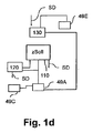
図1dによる別の実施構成では、ハイブリッド車両において、駆動用エネルギー源として使用される高圧蓄電池49Eを冗長なエネルギー供給部として使用すると規定される。それは、同じく第一のエネルギー源49Aから独立しており、そのため、バイパス制御機器130のための冗長なエネルギー源として使用することができる。
Another implementation according to FIG. 1d provides that in a hybrid vehicle, the high-
それに代わって、追加の冗長なオンボード網を取り付けることもできる。 Alternatively, an additional redundant onboard network can be installed.
第一の切換位置Z1では、3/2ポートバルブ16は電流を流されない、即ち、3/2ポートバルブ16は、バイパス制御機器130によりバイパス信号SUを用いて駆動されない。そのため、この第一の切換位置Z1は、3/2ポートバルブ16がバイパス信号SUを与えられること無く自動的に復帰する安定した切換位置であり、そのことは、例えば、バネ付勢により実現することができる。従って、バイパス制御機器130又は第二のエネルギー源49Bの障害時でも、フットブレーキバルブ11が操作されない場合に、バイパス排気部17を介した圧力排出を実現することが、そのため、場合によっては、事前に操作された制動の撤回を実現することが保証される。第二の切換位置Z2は、3/2ポートバルブ16に電流を流す役割を果たす相応のバイパス信号SUを出力することにより達成される。
In the first switching position Z1, the 3/2
冗長的な場合に電子的に与えられる段階的な制動作用を実現できるようにするためにも、3/2ポートバルブ16は、バイパス制御機器130によってパルス形態で、例えば、パルス幅変調されたバイパス信号SUを用いて駆動される。即ち、3/2ポートバルブ16は、第一の切換位置Z1と第二の切換位置Z2の間を交互に切り換えられる。それによって、フットブレーキ排気ポート11eに対して、パルス状のフットブレーキ入力圧力pEが与えられ、その圧力は、制御ポート11a,11bを介して、この場合、大気圧pAtm(第一の切換位置Z1)とバイパス貯蔵圧力pVC(第二の切換位置Z2)の間を往復して変動する、同様にパルス状の常用ブレーキ・制御圧pA,pBを各ブレーキ回路A,Bに供給する。
In order to be able to realize a stepwise braking action which is electronically provided in the case of redundancy, the 3/2
例えば、そのようなフットブレーキ入力圧力pEの時間的な推移が図2に図示されており、バイパス信号SUのパルス幅変調(PWM)によって、フットブレーキ入力圧力の推移(破線の推移)pEpwmが得られ、その推移は、特に、バイパス信号SU、即ち、3/2ポートバルブ16に電流を流すことによるパルス駆動の時間長を表すパルス時間t1と、3/2ポートバルブ16の無電流状態の時間長を表す休止時間t2とに依存する。このパルス時間t1は5ms〜1,000msであり、この休止時間t2は0ms〜2,000msであるとすることができる。フットブレーキ入力圧力の推移pEpwmは、大気圧pAtmとほぼバイパス貯蔵圧力pVCとの間を往復して変動し、その結果、時点tに応じて、異なるフットブレーキ入力圧力pEが出力される。この場合、3/2ポートバルブ16が再び第一の切換位置Z1に戻される前に、フットブレーキ入力圧力pEが、管路の貫流によりパルス時間t1内にバイパス貯蔵圧力pVCにまで上昇できないので、完全にはバイパス貯蔵圧力pVCに到達しない。
For example, such a time course of the footbrake input pressure pE is illustrated in FIG. 2 and pulse width modulation (PWM) of the bypass signal SU yields the footbrake input pressure course (dashed line course) pEpwm. In particular, the transition is represented by the bypass signal SU, that is, the pulse time t1 indicating the time length of the pulse driving by passing the current through the 3/2
変動するフットブレーキ入力圧力の推移pEpwmを滑らかにし、そのため、より細かい調整を実現するために、バイパス圧力媒体貯蔵部20Cからの圧力媒体に関する狭隘部である絞り弁25が配備される。この絞り弁25によって、バイパス圧力媒体貯蔵部20Cから第二のポート入力16bへの体積流量Qを低減することができる。そのため、ポート出力16cにおいて、第二の切換位置Z2への切換時に、バイパス貯蔵圧力pVCがゆっくり上昇し、その結果、フットブレーキ入力圧力pEが低い場合に、早くも3/2ポートバルブ16が第一の切換位置Z1に戻される。従って、フットブレーキ入力圧力の推移pEpwmが滑らかになって、図2に図示された滑らかなフットブレーキ入力圧力の推移pEgl(実線の推移)が得られ、その推移は、最早大きくは上昇せず、そのため、制動時の急激な動きを緩和する役割を果たす。
A
バイパス信号SUを用いたパルス幅変調駆動による、変動する圧力の推移pEpwmと滑らかな圧力の推移pEglは、パルス時間t1と休止時間t2に関して、ロック傾向に有る車輪の回復を実施できることを保証する時間を使用する場合に、一種の間欠制動SFのように作用するので、走行安定性に有利に作用する。それは、例えば、フットブレーキ入力圧力pE又は常用ブレーキ・ブレーキ圧p1,p2,p3,p4が少なくとも、例えば、0.25秒の限界時間の間、例えば、1バールの限界圧力を反復して下回る場合である。このような場合に、ロック傾向に有る車輪が再び回転することが保証される。 The time-varying pressure transition pEpwm and the smooth pressure transition pEgl due to the pulse width modulation drive using the bypass signal SU is a time period for guaranteeing that the wheel having the lock tendency can be recovered with respect to the pulse time t1 and the rest time t2. When it is used, since it acts like a kind of intermittent braking SF, it advantageously acts on running stability. It is, for example, if the footbrake input pressure pE or the service brake braking pressures p1, p2, p3, p4 is repeatedly below the limiting pressure of, for example, 1 bar, for at least a limiting time of, for example, 0.25 seconds. Is. In such a case, it is guaranteed that the wheel, which has a tendency to lock, will rotate again.
それは、特に、冗長な場合に、常用ブレーキ制御機器110によるブレーキスリップ制御と相応の制御信号SA,SBによる各アクスルモデュレータ9,10の電気駆動が最早機能しない時に有利である。この場合、パルス時間t1と休止時間t2は、冗長的な介入時に減速、走行安定性及び操舵可能性に関して受け入れ可能な値を保証できるように設計することができる。
It is particularly advantageous when, in the redundant case, the brake slip control by the service
図示された実施構成により前車軸VAの第一の常用ブレーキ・制御圧pAをタップして測定する追加の圧力センサー又は圧力スイッチ18によって、更に、常用ブレーキ制御機器110又はフットブレーキバルブ11の電気的な機能の障害時において、運転者がフットブレーキバルブ11により制動を要求しているのかをバイパス制御機器130が検知できることを実現できる。それによって、運転者が制動に能動的に介入したことを推定することができ、従って、バイパス制御機器130による冗長的な電子空気圧式制動を中断することができる。他方、この情報を車両200の別の支援システムに転送することもでき、その結果、そのシステムが、常用ブレーキ制御機器110の障害時に、運転者の要求に頼ることができる。更に、妥当性確認によって、電子空気圧式制動システム100aにおける潜在的な誤りを検知することができる。
By means of an additional pressure sensor or
図4では、代替実施構成によるフットブレーキバルブ11が、フットブレーキ排気ポート11eを介して、第二のバイパスバルブ構成19の切換位置Z1,Z2,Z3に応じて、同様にフットブレーキバルブ11に所定のフットブレーキ入力圧力pEを与えることができる第二のバイパスバルブ構成19の第三のポート19cと接続されている。この場合、第二のバイパスバルブ構成19は、二つの2/2ポートバルブ19.1,19.2から構成され、これらは、電気的な駆動に応じて、第二のバイパスバルブ構成19の第一の切換位置Z1では、第一のポート19aを介して、第三のポート19cをバイパス排気部17と短絡し、第二のバイパスバルブ構成19の第二の切換位置Z2では、第二のポート19bを介して、第三のポート19cをバイパス圧力媒体貯蔵部20Cと短絡する。
In FIG. 4, the
それを実現するために、第二のバイパスバルブ構成19の第一の切換位置Z1では、第二の2/2ポートバルブ19.2が閉じられて、第一の2/2ポートバルブ19.1が開かれる。第二のバイパスバルブ構成19の第二の切換位置Z2では、第二の2/2ポートバルブ19.2が開かれて、第一の2/2ポートバルブ19.1が閉じられる。第二のバイパスバルブ構成19の第三の切換位置Z3において二つの2/2ポートバルブ19.1,19.2を閉じることによって、フットブレーキ入力圧力pEを維持することもできる。
To achieve this, in the first switching position Z1 of the second
二つの2/2ポートバルブ19.1,19.2は、バイパス制御機器130によって、バイパス信号SUに基づき制御される。それにより、図1aの3/2ポートバルブ16と同様に、常用ブレーキ・制御圧pA,pBの空気圧式付与は、アクスルモデュレータ9,10を冗長的に空気圧により駆動するためのフットブレーキ入力圧力pEに応じて電子的に制御する形で行なうこともできる。
The two 2/2-port valves 19.1 and 19.2 are controlled by the
図5では、アクスルモデュレータ9,10の電子駆動部の無い純粋な空気圧式制動システム100bが図示されている。即ち、第一と第二のブレーキ回路A,Bでは、通常の動作において、専ら各空気圧制御入力9a,10aを介したアクスルモデュレータ9,10に対する空気圧式付与によって制動される。ABS機能を実現するために、常用ブレーキ制御機器110による電気制御が行なわれる。そのために、前車軸VAと後車軸HAの車輪ブレーキ1,2の前には、それぞれ二つのABS制御バルブ12,13が接続され、それらのバルブによって、常用ブレーキ制御機器110により制御される形で、前車軸VAの車輪5,6の中の一つ又は後車軸HAの車輪7,8の中の一つでブレーキスリップが発生した場合に対処することができる。この場合、上述した通り、冗長な場合に、第一のバイパスバルブ構成16又は3/2ポートバルブによって、電子空気圧式付与V2を実施することができる。前の図による実施形態は、この純粋な空気圧式制動システム100bにも同様に適用することが可能である、即ち、常用ブレーキ・制御圧pA,pBを電子空気圧方式により付与するために、特に、第一のバイパスバルブ構成16の代わりに、二つの2/2ポートバルブ19.1,19.2を備えた第二のバイパスバルブ構成19を使用することもできる。
In FIG. 5, a pure
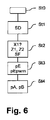
制動システム100a,100bの駆動は、図6に基づき、例えば、以下の通り実施することができる。
The driving of the
最初の工程St0において、例えば、車両200の始動により、本方法が開始する。
In the first step St0, the method is started, for example, by starting the
第一の工程St1において、バイパス制御機器130からの診断信号SDによって、アクスルモデュレータ9,10の電気駆動部に障害又は故障が存在するのかが確認される。
In the first step St1, it is confirmed by the diagnostic signal SD from the
そのような場合、即ち、冗長な場合が生じている場合、第二の工程St2において、各バイパスバルブ構成16,19を第一の切換位置Z1から第二の切換位置Z2に切り換えて、車両200を安全な状態に制動するために、バイパス信号SUが、バイパス制御機器130から各バイパスバルブ構成16,19に出力される。この電気的に制御された制動は、例えば、運転者が手動により制動に介入しないことが、即ち、電子空気圧式付与V2を阻止する、コントロールピストン50の第一の制御位置X1に設定されていないことが確認された場合に実行することができる。それは、例えば、圧力センサー又は圧力スイッチ18により行なうことができる。
In such a case, that is, when a redundant case occurs, in the second step St2, the
冗長的な場合に間欠制動機能SFを実現して、それにより走行安定性及び操舵可能性を改善するために、バイパス信号SUは、パルス幅変調された形で与えることもできる、即ち、第一と第二の切換位置Z1,Z2の間を往復して切り換えられる。 In order to realize the intermittent braking function SF in the redundant case and thereby improve the driving stability and steerability, the bypass signal SU can also be provided in pulse-width modulated form, i.e. And the second switching positions Z1 and Z2.
各バイパスバルブ構成16,19の一つの3/2ポートバルブ16又は二つの2/2ポートバルブ19.1,19.2に電流が流れるために、第三の工程St3において、連続して駆動された場合に、場合によっては、圧力を適合されたバイパス貯蔵圧力pVCに一致する、或いはパルス幅変調により駆動された場合に、パルス状のフットブレーキ入力圧力の推移pEpwm,pEflに一致するフットブレーキ入力圧力pEがフットブレーキバルブ11のフットブレーキ排気ポート11eに出力される。それによって、第四の工程St4において、フットブレーキバルブ11が操作されない場合に、相応の常用ブレーキ・制御圧pA,pBがアクスルモデュレータ9,10に出力され、更に、相応の常用ブレーキ・ブレーキ圧p1,p2,p3,p4が生成される。
In order for the current to flow in one 3/2-
1,2,3,4 車輪ブレーキ
5,6,7,8 車輪
9 第一のアクスルモデュレータ
9a 第一の空気圧制御入力
10 第二のアクスルモデュレータ
10a 第二の空気圧制御入力
11 フットブレーキバルブ
11a 第一の制御ポート
11b 第二の制御ポート
11c 第一の供給ポート
11d 第二の供給ポート
11e フットブレーキ排気ポート
11f 作動空間
12,13 ABS制御バルブ
14 パーキングブレーキ・リレーバルブ
15 パーキングブレーキバルブ
16 第一のバイパス構成(3/2ポートバルブ)
16a 第一のポート入力
16b 第二のポート入力
16c ポート出力
17 バイパス排気部
18 圧力センサー/圧力スイッチ
19 第二のバイパス構成
19.1 第一の2/2ポートバルブ
19.2 第二の2/2ポートバルブ
19a 第一のポート
19b 第二のポート
19c 第三のポート
20A 第一のブレーキ回路Aの第一の圧力媒体貯蔵部
20B 第二のブレーキ回路Bの第二の圧力媒体貯蔵部
20C バイパス圧力媒体貯蔵部
21 トレーラー・制御バルブ
25 絞り弁
49A 第一のエネルギー源
49B 第二のエネルギー源
49C 発電機
49D 一時蓄電池
49E 高圧蓄電池
50 コントロールピストン
51 第一のピストン
52 第一の吸入開口部
53 開口部
54 第二のピストン
55 第三のピストン
56 第四のピストン
57 第二の吸入開口部
58 タペット
61 排気空間
100a 電子空気圧式制動システム
100b 純粋な空気圧式制動システム
110 常用ブレーキ制御機器(ECU)
120 支援制御機器(ADAS−ECU)
130 バイパス制御機器(バイパスECU)
200 車両
A,B,C ブレーキ回路
fPB パーキングブレーキ力
p1,p2,p3,p4 常用ブレーキ・ブレーキ圧
pA,pB 常用ブレーキ・制御圧
pAtm 大気圧
pC パーキングブレーキ・制御圧
pE フットブレーキ入力圧力
pEpwm フットブレーキ入力圧力の推移
pEgl フットブレーキ入力圧力の滑らかな推移
pG 限界圧力
pHigh 高い圧力レベル
pLow 低い圧力レベル
pPB パーキングブレーキ・ブレーキ圧
pVA 第一の圧力媒体貯蔵部20A内の貯蔵圧力
pVB 第二の圧力媒体貯蔵部20B内の貯蔵圧力
pVC バイパス圧力媒体貯蔵部20C内のバイパス貯蔵圧力
Q 体積流量
SA,SB 制御信号
SD 診断信号
SF 間欠制動機能
SU バイパス信号
t 時点
t1 パルス時間
t2 休止時間
V1 機械式付与
V2 電子空気圧式付与
VA,HA 車両軸
W 操作行程
X1 コントロールピストン50の第一の制御位置
X2 コントロールピストン50の第二の制御位置
Z1,Z2 切換位置
zSoll 車両目標減速
St1,St2,St3,St4 本方法の工程
1, 2, 3, 4
16a
120 Support control equipment (ADAS-ECU)
130 Bypass control device (bypass ECU)
200 Vehicle A, B, C Brake circuit fPB Parking brake force p1, p2, p3, p4 Service brake/brake pressure pA, pB Service brake/control pressure pAtm Atmospheric pressure pC Parking brake/control pressure pE Foot brake input pressure pEpwm Foot brake Transition of input pressure pEgl Foot brake Smooth transition of input pressure pG Limit pressure pHhigh High pressure level pLow Low pressure level pPB Parking brake/brake pressure pVA Storage pressure in first pressure
Claims (19)
車両(200)の車輪(5,6,7,8)を制動する車輪ブレーキ(1,2,3,4)と、
アクスルモデュレータ(9,10)に対して常用ブレーキ・制御圧(pA,pB)を空気圧により与えるためのフットブレーキバルブ(11)と、
フットブレーキバルブ(11)に対して電子空気圧式付与(V2)としての役割を果たすフットブレーキ入力圧力(pE)を与えるためのバイパスバルブ構成(16,19)と、
を備え、
これらの車輪ブレーキ(1,2,3,4)には、アクスルモデュレータ(9,10)によって、常用ブレーキ・制御圧(pA,pB)に応じた常用ブレーキ・ブレーキ圧(p1,p2,p3,p4)を与えることが可能であり、
常用ブレーキ・制御圧(pA,pB)は、フットブレーキバルブ(11)によって、機械式付与(V1)又は電子空気圧式付与(V2)に応じて生成することが可能であり、
バイパスバルブ構成(16,19)は、フットブレーキバルブ(11)に対して、電子空気圧式付与(V2)として、第一の切換位置(Z1)で低い圧力レベル(pLow)を与え、第二の切換位置(Z2)で高い圧力レベル(pHigh)を与え、その結果、低い圧力レベル(pLow)及び/又は高い圧力レベル(pHigh)に応じて、フットブレーキ入力圧力(pE)を与えることが可能である、
電子的に制御可能な空気圧式制動システムにおいて、
このバイパスバルブ構成(16,19)が、フットブレーキバルブ(11)の排気空間(61)とフローに関して接続されており、その結果、電子空気圧式付与(V2)としてバイパスバルブ構成(16,19)により与えられるフットブレーキ入力圧力(pE)が、常用ブレーキ・制御圧(pA,pB)として、フットブレーキバルブ(11)の排気空間(61)と作動空間(11f)を介して、直にアクスルモデュレータ(9,10)に貫流することができる、
ことを特徴とする電子的に制御可能な空気圧式制動システム。 An electronically controllable pneumatic braking system (100a, 100b) for a vehicle (200), especially a commercial vehicle (200),
Wheel brakes (1, 2, 3, 4) for braking the wheels (5, 6, 7, 8) of the vehicle (200),
A foot brake valve (11) for pneumatically applying a regular brake/control pressure (pA, pB) to the axle modulator (9, 10),
A bypass valve arrangement (16, 19) for providing a foot brake input pressure (pE) which serves as an electropneumatic application (V2) to the foot brake valve (11);
Equipped with
These wheel brakes (1, 2, 3, 4) are connected to service brakes/brake pressures (p1, p2, pB) corresponding to service brakes/control pressures (pA, pB) by an axle modulator (9, 10). p3, p4) can be given,
The service brake/control pressure (pA, pB) can be generated by the foot brake valve (11) according to mechanical application (V1) or electronic pneumatic application (V2),
The bypass valve arrangement (16, 19) provides the foot brake valve (11) with a low pressure level (pLow) at the first switching position (Z1) as an electro-pneumatic application (V2) and a second It is possible to provide a high pressure level (pHhigh) in the switching position (Z2) and consequently a footbrake input pressure (pE) in response to a low pressure level (pLow) and/or a high pressure level (pHhigh). is there,
In an electronically controllable pneumatic braking system,
This bypass valve arrangement (16, 19) is connected in flow with the exhaust space (61) of the footbrake valve (11), so that the bypass valve arrangement (16, 19) as an electropneumatic application (V2). The foot brake input pressure (pE) given by is directly used as the normal brake/control pressure (pA, pB) through the exhaust space (61) and the working space (11f) of the foot brake valve (11). Can flow through the durator (9, 10),
An electronically controllable pneumatic braking system characterized in that
フットブレーキバルブ(11)のコントロールピストン(50)が第二の制御位置(X2)にシフトされた、フットブレーキバルブ(11)の機械的に操作されない位置では、排気空間(61)が、作動空間(11f)を介して制御ポート(11a,11b)とフローに関して接続され、その結果、機械的に操作されない位置では、常用ブレーキ・制御圧(pA,pB)が、電子空気圧式付与(V2)に応じてのみ与えることが可能であることと、
を特徴とする請求項1から5までのいずれか一つに記載の電子的に制御可能な空気圧式制動システム(100a,100b)。 In the mechanically actuated position of the foot brake valve (11), the exhaust space (61) is activated, with the control piston (50) of the foot brake valve (11) being shifted to the first control position (X1). There is no flow connection with the control ports (11a, 11b) via the space (11f), so that in the operated position of the foot brake valve (11) the service brake/control pressure (pA, pB) is not It is possible to give only according to the expression assignment (V1),
In the mechanically unoperated position of the foot brake valve (11), where the control piston (50) of the foot brake valve (11) is shifted to the second control position (X2), the exhaust space (61) is The control ports (11a, 11b) are connected with respect to the flow via (11f), and as a result, the service brake/control pressure (pA, pB) is applied to the electropneumatic application (V2) in a position where it is not mechanically operated. Can only be given according to
Electronically controllable pneumatic braking system (100a, 100b) according to any one of the preceding claims.
第二のバイパスバルブ構成(19)の第一の切換位置(Z1)では、第一の2/2ポートバルブ(19.1)により、低い圧力レベル(pLow)を排気空間(61)に与えることが可能であると同時に、第二の2/2ポートバルブ(19.2)により、排気空間(61)への高い圧力レベル(pHigh)の付与を阻止することが可能であり、
第二のバイパスバルブ構成(19)の第二の切換位置(Z2)では、第一の2/2ポートバルブ(19.1)による低い圧力レベル(pLow)の付与を阻止することが可能であると同時に、第二の2/2ポートバルブ(19.2)により、高い圧力レベル(pHigh)を排気空間(61)に与えることが可能である、
ことを特徴とする請求項1から7までのいずれか一つに記載の電子的に制御可能な空気圧式制動システム(100a,100b)。 A second bypass valve arrangement (19) comprises two 2/2 port valves (19.1, 19.2), the first 2/2 port valve (19.1) allowing, for example, a bypass exhaust From (17) it is possible to provide a low pressure level (pLow) to the exhaust space (61) and a second 2/2 port valve (19.2) allows for example bypass pressure medium reservoir (20C). From which it is possible to provide a high pressure level (pH high) to the exhaust space (61),
In the first switching position (Z1) of the second bypass valve configuration (19), the first 2/2 port valve (19.1) provides a low pressure level (pLow) to the exhaust space (61). At the same time, it is possible to prevent the application of a high pressure level (pHhigh) to the exhaust space (61) by means of the second 2/2 port valve (19.2),
In the second switching position (Z2) of the second bypass valve arrangement (19) it is possible to prevent the application of a low pressure level (pLow) by the first 2/2 port valve (19.1). At the same time, a second 2/2 port valve (19.2) makes it possible to provide a high pressure level (pHhigh) to the exhaust space (61),
Electronically controllable pneumatic braking system (100a, 100b) according to any one of the preceding claims.
アクスルモデュレータ(9,10)の電子的な駆動(SA,SB)時に障害又は故障が存在するのかを確認する工程(St1)と、
障害又は故障が確認されるとともに、フットブレーキバルブ(11)の操作が行なわれない場合に、電子空気圧式付与(V2)の実施により冗長性を実現するために、バイパス信号(SU)によりバイパスバルブ構成(16,19)を駆動する工程(St2)と、
バイパスバルブ構成(16,19)から、フットブレーキバルブ(11)の排気空間(61)及び/又はフットブレーキ排気ポート(11e)に、電子空気圧式付与(V2)としてフットブレーキ入力圧力(pE)を出力する工程(St3)と、
車輪ブレーキ(1,2,3,4)の冗長的な電子空気圧式操作のために、常用ブレーキ・制御圧(pA,pB)としてフットブレーキ入力圧力(pE)をアクスルモデュレータ(9,10)に直に転送する工程(St4)と、
を有する方法。 A method of electronically controlling a pneumatic braking system (100a, 100b) according to any one of claims 1 to 13, wherein at least an electronic drive of an axle modulator (9, 10) ( A step (St1) of confirming whether there is a failure or a failure at the time of SA, SB),
When a fault or failure is confirmed and the foot brake valve (11) is not operated, the bypass valve (SU) is used to realize redundancy by implementing electropneumatic application (V2). A step (St2) of driving the configuration (16, 19),
From the bypass valve configuration (16, 19) to the exhaust space (61) of the foot brake valve (11) and/or the foot brake exhaust port (11e), the foot brake input pressure (pE) is applied as an electronic pneumatic type (V2). Output step (St3),
For redundant electropneumatic operation of the wheel brakes (1, 2, 3, 4), the foot brake input pressure (pE) is used as the service brake/control pressure (pA, pB) for the axle modulator (9, 10). ), the process of directly transferring to () (St4),
A method having.
このバイパスバルブ構成(16,19)が、バイパス信号(SU)により駆動されない場合に第一の切換位置(Z1)に移行し、バイパス信号(SU)により駆動された場合に第二の切換位置(Z2)に移行する、
ことを特徴とする請求項14に記載の方法。 A bypass valve arrangement (16, 19) is electrically driven by a bypass signal (SU) provided by a bypass control device (130),
The bypass valve configuration (16, 19) shifts to the first switching position (Z1) when not driven by the bypass signal (SU), and moves to the second switching position (Z1) when driven by the bypass signal (SU). Z2),
15. The method according to claim 14, characterized in that
そのために、バイパスバルブ構成(16,19)が、パルス時間(t1)の間は第二の切換位置(Z2)に置かれ、休止時間(t2)の間は第一の切換位置(Z1)に置かれ、その結果、常用ブレーキ・ブレーキ圧(p1,p2,p3,p4)が、間欠制動機能(SF)を実現するように変動する、
ことを特徴とする請求項15に記載の方法。 A bypass control device (130) provides a bypass signal (SU) in pulse width modulated form, whereby the bypass valve arrangement (16, 19) causes the first switching position (Z1) and the second switching position (SU). Z2) is switched back and forth alternately,
To that end, the bypass valve arrangement (16, 19) is placed in the second switching position (Z2) during the pulse time (t1) and in the first switching position (Z1) during the rest time (t2). Is placed, and as a result, the service brake pressure (p1, p2, p3, p4) fluctuates to achieve the intermittent braking function (SF),
16. The method according to claim 15, characterized in that
Applications Claiming Priority (3)
| Application Number | Priority Date | Filing Date | Title |
|---|---|---|---|
| DE102016010464.3 | 2016-08-31 | ||
| DE102016010464.3A DE102016010464A1 (en) | 2016-08-31 | 2016-08-31 | An electronically controllable pneumatic braking system in a utility vehicle and method for electronically controlling a pneumatic braking system in a utility vehicle |
| PCT/EP2017/000860 WO2018041385A1 (en) | 2016-08-31 | 2017-07-17 | Electronically controllable pneumatic brake system in a utility vehicle and method for electronically controlling a pneumatic brake system in a utility vehicle |
Publications (2)
| Publication Number | Publication Date |
|---|---|
| JP2019524543A JP2019524543A (en) | 2019-09-05 |
| JP6743343B2 true JP6743343B2 (en) | 2020-08-19 |
Family
ID=59579586
Family Applications (1)
| Application Number | Title | Priority Date | Filing Date |
|---|---|---|---|
| JP2019503730A Active JP6743343B2 (en) | 2016-08-31 | 2017-07-17 | Electronically controllable pneumatic braking system for commercial vehicles and electronic control method for pneumatic braking system of commercial vehicles |
Country Status (6)
| Country | Link |
|---|---|
| US (1) | US11034341B2 (en) |
| EP (1) | EP3507154B1 (en) |
| JP (1) | JP6743343B2 (en) |
| CN (1) | CN109562754B (en) |
| DE (1) | DE102016010464A1 (en) |
| WO (1) | WO2018041385A1 (en) |
Families Citing this family (20)
| Publication number | Priority date | Publication date | Assignee | Title |
|---|---|---|---|---|
| DE102015011296A1 (en) * | 2015-09-02 | 2017-03-02 | Wabco Gmbh | Electronically controllable pneumatic braking system in a utility vehicle and method for electronically controlling a pneumatic braking system |
| DE102016010464A1 (en) * | 2016-08-31 | 2018-03-01 | Wabco Gmbh | An electronically controllable pneumatic braking system in a utility vehicle and method for electronically controlling a pneumatic braking system in a utility vehicle |
| DE102016010462A1 (en) * | 2016-08-31 | 2018-03-01 | Wabco Gmbh | An electronically controllable pneumatic braking system in a utility vehicle and method for electronically controlling a pneumatic braking system in a utility vehicle |
| KR102419313B1 (en) * | 2018-02-21 | 2022-07-12 | 히다치 아스테모 가부시키가이샤 | Electric brakes and controls |
| EP3626564B1 (en) * | 2018-09-18 | 2021-02-24 | WABCO Europe BVBA | Control valve, electronically controllable brake system and method for controlling the electronically controllable brake system |
| EP3626563B1 (en) * | 2018-09-18 | 2021-01-27 | WABCO Europe BVBA | Control valve, electronically controllable brake system and method for controlling the electronically controllable brake system |
| EP3798072B1 (en) | 2019-09-26 | 2021-10-13 | Haldex Brake Products Aktiebolag | Brake system for a commercial vehicle |
| CN110667548B (en) * | 2019-10-17 | 2021-01-15 | 清华大学 | Redundant braking method and system for brake-by-wire system and storage medium |
| EP4061677B1 (en) * | 2019-11-18 | 2023-08-09 | ZF CV Systems Global GmbH | Redundancy valve unit, electrically controlled pneumatic brake system, method for controlling a brake system |
| DE102019131110A1 (en) | 2019-11-18 | 2021-05-20 | Wabco Europe Bvba | Brake system with safe emergency stop function and procedure for this |
| DE102019133010A1 (en) | 2019-12-04 | 2021-06-10 | Zf Cv Systems Global Gmbh | Fail-safe valve unit for a parking brake function and a parking brake valve arrangement |
| DE102019133011A1 (en) | 2019-12-04 | 2021-06-10 | Zf Cv Systems Global Gmbh | Parking brake valve arrangement designed to be monostable and fault-tolerant |
| DE102019133012A1 (en) * | 2019-12-04 | 2021-06-10 | Zf Cv Systems Global Gmbh | Electrically controllable pneumatic braking system with a two-channel pressure modulator system |
| EP3835153B1 (en) * | 2019-12-13 | 2022-12-07 | KNORR-BREMSE Systeme für Nutzfahrzeuge GmbH | Valve arrangement |
| US11679748B2 (en) * | 2020-08-03 | 2023-06-20 | Zf Cv Systems Europe Bv | Electronically controlled pneumatic brake system comprising an electronically controlled trailer control module |
| DE102020130276A1 (en) | 2020-11-17 | 2022-05-19 | Zf Cv Systems Global Gmbh | Failsafe valve assembly, electronically controllable pneumatic braking system, vehicle, method |
| DE102021103478A1 (en) | 2021-02-15 | 2022-08-18 | Zf Cv Systems Global Gmbh | Method and braking system for emergency stopping of a commercial vehicle |
| DE102021112831A1 (en) | 2021-05-18 | 2022-11-24 | Zf Cv Systems Global Gmbh | Electropneumatic assembly with integrated failsafe valve arrangement for multiple errors, electronically controllable pneumatic brake system, and method for operating a brake system |
| DE102021122501A1 (en) | 2021-08-31 | 2023-03-02 | Zf Cv Systems Global Gmbh | Electronically controllable pneumatic braking system with a fail-safe braking application for autonomous driving with only one shuttle valve |
| EP4163167B1 (en) * | 2021-10-07 | 2024-04-03 | Volvo Truck Corporation | Commercial vehicle comprising a pneumatic system and method for controlling a pneumatic system |
Family Cites Families (30)
| Publication number | Priority date | Publication date | Assignee | Title |
|---|---|---|---|---|
| JPH03126756U (en) * | 1990-04-06 | 1991-12-20 | ||
| JP3269424B2 (en) * | 1997-03-04 | 2002-03-25 | 三菱自動車工業株式会社 | Rear two-axle brake control system |
| JP4117425B2 (en) * | 1998-07-29 | 2008-07-16 | 三菱ふそうトラック・バス株式会社 | Braking control device for connected vehicles |
| JP3745127B2 (en) * | 1998-09-25 | 2006-02-15 | 日産ディーゼル工業株式会社 | Brake device for tractor |
| DE19954568A1 (en) * | 1999-11-12 | 2001-05-17 | Knorr Bremse Systeme | Hydraulic vehicle brake system |
| DE10004086C2 (en) * | 2000-01-31 | 2001-12-06 | Knorr Bremse Systeme | Brake system for vehicles, in particular commercial vehicles |
| DE10236922A1 (en) | 2002-08-12 | 2004-03-04 | Knorr-Bremse Systeme für Nutzfahrzeuge GmbH | Pressure control module for a compressed air brake system of a vehicle |
| US20050218719A1 (en) | 2004-04-02 | 2005-10-06 | Cem Hatipoglu | Use of ECU to control brake valve actuator |
| DE102005060225A1 (en) * | 2005-12-16 | 2007-06-21 | Wabco Gmbh | Electro-pneumatic automotive parking brake has automatic throttled compressed air bleed line to the spring energy storage brake cylinder |
| DE102007052439A1 (en) | 2007-11-02 | 2009-05-07 | Wabco Gmbh | Driver assistance system |
| DE102010008375A1 (en) * | 2010-02-17 | 2011-08-18 | Voith Patent GmbH, 89522 | Method for operating a hydraulic or pneumatic system |
| DE102010050578A1 (en) | 2010-11-05 | 2012-05-10 | Wabco Gmbh | System with valve means for a pneumatically operated brake system, valve means, brake confirmation means, trailer control valve means and means for controlling the system, brake system, vehicle, use of a component and method of retooling a brake system |
| DE102010050580A1 (en) | 2010-11-05 | 2012-05-10 | Wabco Gmbh | Valve device, brake system and vehicle |
| EP2532559B1 (en) | 2011-06-08 | 2015-05-20 | WABCO GmbH | Vehicle braking system |
| DE102012015949A1 (en) | 2012-08-10 | 2014-03-06 | Audi Ag | Method for controlling the charging operation of an electric motor vehicle |
| CN103342098B (en) * | 2013-07-25 | 2016-08-17 | 祥天控股(集团)有限公司 | Pneumatic vehicle |
| DE102013015949A1 (en) | 2013-09-25 | 2015-03-26 | Wabco Gmbh | Brake system and method for curve support |
| DE102013015971A1 (en) | 2013-09-25 | 2015-04-09 | Wabco Gmbh | Brake device and use of a directional control valve in a brake device |
| DE102014112014A1 (en) * | 2014-08-22 | 2016-02-25 | Knorr-Bremse Systeme für Nutzfahrzeuge GmbH | Method for controlling a service brake device of a vehicle and service brake valve device for such a service brake device |
| DE102014013756C5 (en) * | 2014-09-22 | 2018-04-26 | Knorr-Bremse Systeme für Nutzfahrzeuge GmbH | Electrical equipment of a vehicle with at least partially electrical braking and steering device with high availability |
| DE102015011296A1 (en) * | 2015-09-02 | 2017-03-02 | Wabco Gmbh | Electronically controllable pneumatic braking system in a utility vehicle and method for electronically controlling a pneumatic braking system |
| DE102015016721A1 (en) * | 2015-12-22 | 2017-06-22 | Wabco Gmbh | A method of regulating vehicle actual deceleration in a vehicle having an ABS braking system |
| CN105604919B (en) * | 2016-03-11 | 2017-11-17 | 东风商用车有限公司 | A kind of vehicle air compressor energy conserving system and its control method |
| DE102016005318A1 (en) * | 2016-05-02 | 2017-11-02 | Wabco Gmbh | Electronically controllable pneumatic braking system in a utility vehicle and method for electronically controlling a pneumatic braking system. |
| DE102016010462A1 (en) * | 2016-08-31 | 2018-03-01 | Wabco Gmbh | An electronically controllable pneumatic braking system in a utility vehicle and method for electronically controlling a pneumatic braking system in a utility vehicle |
| DE102016010464A1 (en) * | 2016-08-31 | 2018-03-01 | Wabco Gmbh | An electronically controllable pneumatic braking system in a utility vehicle and method for electronically controlling a pneumatic braking system in a utility vehicle |
| DE102016010463A1 (en) * | 2016-08-31 | 2018-03-01 | Wabco Gmbh | Method for electronically controlling a pneumatic brake system in a vehicle, in particular a commercial vehicle, and electronically controllable pneumatic brake system |
| DE102016010460A1 (en) * | 2016-08-31 | 2018-03-01 | Wabco Gmbh | An electronically controllable pneumatic braking system in a utility vehicle and method for electronically controlling a pneumatic braking system in a utility vehicle |
| DE102017118263B4 (en) * | 2017-08-10 | 2023-07-06 | Knorr-Bremse Systeme für Nutzfahrzeuge GmbH | Electric parking brake, parking brake system, a commercial vehicle, a method and a computer program product |
| DE102018126312A1 (en) * | 2018-10-23 | 2020-04-23 | Wabco Gmbh | Electropneumatic brake system architecture without direct pneumatic service brake redundancy on the rear axle (1p1e) |
-
2016
- 2016-08-31 DE DE102016010464.3A patent/DE102016010464A1/en not_active Withdrawn
-
2017
- 2017-07-17 JP JP2019503730A patent/JP6743343B2/en active Active
- 2017-07-17 EP EP17751012.0A patent/EP3507154B1/en active Active
- 2017-07-17 CN CN201780045423.7A patent/CN109562754B/en active Active
- 2017-07-17 WO PCT/EP2017/000860 patent/WO2018041385A1/en unknown
- 2017-07-17 US US16/329,225 patent/US11034341B2/en active Active
Also Published As
| Publication number | Publication date |
|---|---|
| CN109562754A (en) | 2019-04-02 |
| EP3507154A1 (en) | 2019-07-10 |
| US11034341B2 (en) | 2021-06-15 |
| DE102016010464A1 (en) | 2018-03-01 |
| JP2019524543A (en) | 2019-09-05 |
| EP3507154B1 (en) | 2020-05-27 |
| CN109562754B (en) | 2021-12-03 |
| WO2018041385A1 (en) | 2018-03-08 |
| US20190248351A1 (en) | 2019-08-15 |
Similar Documents
| Publication | Publication Date | Title |
|---|---|---|
| JP6743343B2 (en) | Electronically controllable pneumatic braking system for commercial vehicles and electronic control method for pneumatic braking system of commercial vehicles | |
| JP6810785B2 (en) | Electronically controllable pneumatic braking system for commercial vehicles and electronic control method for pneumatic braking system for commercial vehicles | |
| JP6689368B2 (en) | Electronically controllable compressed air braking system for commercial vehicles and method for electronically controlling compressed air braking system | |
| JP6774558B2 (en) | A method of electronically controlling the pneumatic braking system of a vehicle and a pneumatic braking system that can be controlled electronically. | |
| JP6810805B2 (en) | Electronically controllable pneumatic braking system in commercial vehicles and electronically controlled pneumatic braking system in commercial vehicles | |
| CN108290563B (en) | Vehicle electropneumatic parking brake device with additional control loop | |
| CN108883755B (en) | Electronically controllable pneumatic brake system in a commercial vehicle and method for electronically controlling a pneumatic brake system | |
| CN111971213B (en) | Hydraulic brake system for motor vehicle | |
| US20180001879A1 (en) | Electronic brake system for a compressed air braking system of a utility vehicle | |
| WO2011145673A1 (en) | Brake device | |
| US20150353067A1 (en) | Electrohydraulic Motor Vehicle Brake System and Method for Operating the Same | |
| CN104029666A (en) | Brake Control Apparatus | |
| CN110035935B (en) | Method for controlling a hydraulic brake system in a vehicle | |
| KR102310690B1 (en) | vehicle brake system | |
| KR20120130234A (en) | Brake system for a vehicle and method for operating a brake system of a vehicle | |
| US20220332302A1 (en) | Brake Control Apparatus | |
| JP6847232B2 (en) | Air treatment units for commercial vehicle braking devices and how to operate the air treatment units | |
| JP6149847B2 (en) | Vehicle braking device | |
| US20220048488A1 (en) | Secondary brake system of a vehicle, and method for controlling it | |
| CN114761294A (en) | Monostable and fault tolerant design parking brake valve assembly | |
| KR20220119160A (en) | Vacuum boost braking system with redundancy | |
| JP2019513615A (en) | Electronically pressure adjustable vehicle brake system and method for controlling an electronically pressure adjustable vehicle brake system | |
| KR20160100372A (en) | Motor vehicle | |
| CN112088115B (en) | Redundant brake unit for a brake system and system using the same | |
| CN108082163B (en) | Brake system for a motor vehicle and method for operating a brake system |
Legal Events
| Date | Code | Title | Description |
|---|---|---|---|
| A621 | Written request for application examination |
Free format text: JAPANESE INTERMEDIATE CODE: A621 Effective date: 20190213 |
|
| A977 | Report on retrieval |
Free format text: JAPANESE INTERMEDIATE CODE: A971007 Effective date: 20200219 |
|
| A131 | Notification of reasons for refusal |
Free format text: JAPANESE INTERMEDIATE CODE: A131 Effective date: 20200226 |
|
| A521 | Request for written amendment filed |
Free format text: JAPANESE INTERMEDIATE CODE: A523 Effective date: 20200515 |
|
| TRDD | Decision of grant or rejection written | ||
| A01 | Written decision to grant a patent or to grant a registration (utility model) |
Free format text: JAPANESE INTERMEDIATE CODE: A01 Effective date: 20200610 |
|
| RD04 | Notification of resignation of power of attorney |
Free format text: JAPANESE INTERMEDIATE CODE: A7424 Effective date: 20200703 |
|
| A61 | First payment of annual fees (during grant procedure) |
Free format text: JAPANESE INTERMEDIATE CODE: A61 Effective date: 20200708 |
|
| R150 | Certificate of patent or registration of utility model |
Ref document number: 6743343 Country of ref document: JP Free format text: JAPANESE INTERMEDIATE CODE: R150 |
|
| R250 | Receipt of annual fees |
Free format text: JAPANESE INTERMEDIATE CODE: R250 |