JP6740756B2 - Imaging device and automobile - Google Patents

Imaging device and automobile Download PDF

Info

Publication number
JP6740756B2
JP6740756B2 JP2016132796A JP2016132796A JP6740756B2 JP 6740756 B2 JP6740756 B2 JP 6740756B2 JP 2016132796 A JP2016132796 A JP 2016132796A JP 2016132796 A JP2016132796 A JP 2016132796A JP 6740756 B2 JP6740756 B2 JP 6740756B2
Authority
JP
Japan
Prior art keywords
vehicle
information
control device
area
region
Prior art date
Legal status (The legal status is an assumption and is not a legal conclusion. Google has not performed a legal analysis and makes no representation as to the accuracy of the status listed.)
Active
Application number
JP2016132796A
Other languages
Japanese (ja)
Other versions
JP2018007077A (en
JP2018007077A5 (en
Inventor
ひとみ 長沼
ひとみ 長沼
栗山 孝司
孝司 栗山
幸一 福田
幸一 福田
祐起 喜多
祐起 喜多
長岡 弘仁
弘仁 長岡
知哉 中川
知哉 中川
政一 関口
政一 関口
孝 塩野谷
孝 塩野谷
Current Assignee (The listed assignees may be inaccurate. Google has not performed a legal analysis and makes no representation or warranty as to the accuracy of the list.)
Nikon Corp
Original Assignee
Nikon Corp
Priority date (The priority date is an assumption and is not a legal conclusion. Google has not performed a legal analysis and makes no representation as to the accuracy of the date listed.)
Filing date
Publication date
Application filed by Nikon Corp filed Critical Nikon Corp
Priority to JP2016132796A priority Critical patent/JP6740756B2/en
Publication of JP2018007077A publication Critical patent/JP2018007077A/en
Publication of JP2018007077A5 publication Critical patent/JP2018007077A5/ja
Application granted granted Critical
Publication of JP6740756B2 publication Critical patent/JP6740756B2/en
Active legal-status Critical Current
Anticipated expiration legal-status Critical

Links

Images

Landscapes

  • Navigation (AREA)
  • Studio Devices (AREA)
  • Traffic Control Systems (AREA)

Description

本発明は、撮像装置および自動車に関する。 The present invention relates to an image pickup device and an automobile.

車両に搭載したカメラが知られている(特許文献1参照)。従来の車両に搭載したカメラでは、車両の位置によって撮影条件の設定を行うことができないという問題がある。 A camera mounted on a vehicle is known (see Patent Document 1). A conventional camera mounted on a vehicle has a problem that it is not possible to set shooting conditions depending on the position of the vehicle.

特開2010−79424号公報JP, 2010-79424, A

本発明の第1の態様による撮像装置は、移動体に搭載される撮像装置において、異なる撮像条件が設定可能である複数の領域を有する撮像部と、前記移動体の位置情報及び前記移動体の進行方向に位置する道路の情報を取得する取得部と、前記複数の領域の撮像条件を設定する設定部と、を備え、前記設定部は、前記移動体の位置情報及び前記移動体の進行方向に位置する道路の情報に基づいて、前記複数の領域のうち前記移動体の進行方向に位置する特定の対象物の領域について、撮像条件を他の領域と異ならせる。An image pickup apparatus according to a first aspect of the present invention is an image pickup apparatus mounted on a moving body, wherein an image pickup unit having a plurality of regions in which different image pickup conditions can be set, position information of the moving body, and the moving body. An acquisition unit that acquires information about a road located in the traveling direction, and a setting unit that sets the imaging conditions of the plurality of regions, wherein the setting unit is the positional information of the moving body and the traveling direction of the moving body. Based on the information of the road located at, the imaging condition is made different from the other areas for the area of the specific object located in the traveling direction of the moving body among the plurality of areas.
本発明の第2の態様による自動車は、第1の態様による撮像装置を搭載する。 A vehicle according to a second aspect of the present invention is equipped with the imaging device according to the first aspect.

車両の運転支援装置の概略構成図である。It is a schematic block diagram of a driving assistance device of a vehicle. 制御装置の構成を例示するブロック図である。It is a block diagram which illustrates the structure of a control apparatus. 撮像チップの画素配列と単位領域を説明する図である。It is a figure explaining the pixel array and unit area of an imaging chip. 撮像素子を有するカメラの構成を例示するブロック図である。It is a block diagram which illustrates the composition of the camera which has an image sensor. 撮像素子に結像される被写体(対象物)の像を模式的に示す図である。It is a figure which shows typically the image of the to-be-photographed object (object) image-formed on an image sensor. 図6(a)は、車両が走行する道路を例示する図、図6(b)は、撮像素子に結像される被写体(対象物)の像を模式的に示す図である。FIG. 6A is a diagram illustrating a road on which a vehicle travels, and FIG. 6B is a diagram schematically illustrating an image of a subject (object) formed on an image sensor. 図7(a)は、図6(a)に比べて車両が進行した状態を例示する図、図7(b)は、撮像素子に結像される被写体(対象物)の像を模式的に示す図である。FIG. 7(a) is a diagram illustrating a state in which the vehicle has advanced compared to FIG. 6(a), and FIG. 7(b) schematically shows an image of a subject (object) formed on an image sensor. FIG. 制御装置が実行するカメラの制御処理の流れを説明するフローチャートである。7 is a flowchart illustrating a flow of camera control processing executed by the control device. 撮像条件設定処理の詳細を説明するフローチャートである。It is a flow chart explaining the details of imaging condition setting processing. 撮像素子に結像される被写体(対象物)の像を模式的に示す図である。It is a figure which shows typically the image of the to-be-photographed object (object) image-formed on an image sensor. 撮像素子の画素領域の部分拡大図である。It is a partially expanded view of a pixel region of an image sensor. 走行する自動車の位置関係を説明する図である。It is a figure explaining the physical relationship of the car which runs. 後続する車両に搭載されるカメラの撮像素子に結像される被写体の像を模式的に示す図である。It is a figure which shows typically the image of the to-be-photographed object image-formed on the image pick-up element of the camera mounted in the following vehicle. 制御装置が実行するカメラの制御処理の流れを説明するフローチャートである。7 is a flowchart illustrating a flow of camera control processing executed by the control device. 図15(a)は、カメラの撮像素子に結像される被写体の像を模式的に示す図である。図15(b)は、カメラの撮像素子に結像される被写体の像を模式的に示す図である。FIG. 15A is a diagram schematically showing an image of a subject formed on the image sensor of the camera. FIG. 15B is a diagram schematically showing an image of a subject formed on the image pickup element of the camera.

(第一の実施の形態)
<カメラの使用場面>
図1は、カメラ3を搭載した車両1の運転支援装置2の概略構成図である。図1において、自動車等の車両1に運転支援装置2が搭載されている。運転支援装置2は、カメラ3と、制御装置4と、第1の走行制御ユニット5と、第2の走行制御ユニット6等により構成される。なお、本実施の形態では内燃機関を駆動源とする例を説明するが、モータを駆動源とするものでもよい。
(First embodiment)
<When to use the camera>
FIG. 1 is a schematic configuration diagram of a driving support device 2 of a vehicle 1 equipped with a camera 3. In FIG. 1, a driving support device 2 is mounted on a vehicle 1 such as an automobile. The driving support device 2 includes a camera 3, a control device 4, a first traveling control unit 5, a second traveling control unit 6, and the like. In the present embodiment, an example in which the internal combustion engine is used as the drive source will be described, but a motor may be used as the drive source.

カメラ3は、複数のレンズを有する撮像光学系、後述する積層型撮像素子を備え、例えば車室内の天井前方に取り付けられている。カメラ3は車両1の前方に向けられ、その取り付け高さ(地面からカメラ3までの距離)は、例えば1.4(m)に調整されている。カメラ3は、車両1の進行方向の画像を取得し、取得した画像に基づいて撮影画面内の複数の位置における各被写体(対象物)までの距離測定(測距)を行う。距離測定は、積層型撮像素子に備えられている焦点検出用画素からの画像信号を用いた測距演算により算出する。測距については後述する。カメラ3により取得された画像のデータおよび測距データは、制御装置4へ送出される。なお、カメラ3を車外に設けてもよく、車内・車外のカメラ3を協働してもよく、カメラ3の数も適宜設定すればよい。一例を挙げると、後述する白線検出は車外のカメラ3を用い、対象物や障害物の認識は、車内・車外のカメラ3を協働させるようにしてもよい。 The camera 3 includes an image pickup optical system having a plurality of lenses and a laminated image pickup element described later, and is attached, for example, in front of the ceiling in the vehicle compartment. The camera 3 is directed to the front of the vehicle 1, and its mounting height (distance from the ground to the camera 3) is adjusted to 1.4 (m), for example. The camera 3 acquires an image in the traveling direction of the vehicle 1 and performs distance measurement (distance measurement) to each subject (object) at a plurality of positions in the photographing screen based on the acquired image. The distance measurement is calculated by distance measurement calculation using image signals from the focus detection pixels provided in the stack-type image sensor. Distance measurement will be described later. The image data and the distance measurement data acquired by the camera 3 are sent to the control device 4. The camera 3 may be provided outside the vehicle, the cameras 3 inside and outside the vehicle may cooperate, and the number of cameras 3 may be set appropriately. As an example, the camera 3 outside the vehicle may be used for white line detection, which will be described later, and the cameras 3 inside and outside the vehicle may be made to cooperate in recognizing an object or obstacle.

制御装置4は、図2に例示するように、CPU4aおよび記憶部4bを含む。CPU4aは、記憶部4bに記憶されている各種プログラムに基づいて、記憶部4bに記憶されている制御パラメータや後述する各センサによる検出信号などを用いて各種演算を行う。 The control device 4 includes a CPU 4a and a storage unit 4b, as illustrated in FIG. The CPU 4a performs various calculations based on various programs stored in the storage unit 4b using control parameters stored in the storage unit 4b and detection signals from each sensor described later.

第1の走行制御ユニット5は、制御装置4からの指示に基づいて、定速走行制御および追従走行制御を行う。定速走行制御は、所定の制御プログラムに基づいて、車両1を一定速度で走行させる制御である。追従走行制御は、定速走行制御を行っている際に、制御装置4にて認識された先行車の速度が車両1に設定されている目標速度以下の場合には、先行車に対して一定の車間距離を保持した状態で走行させる制御である。 The first traveling control unit 5 performs constant-speed traveling control and follow-up traveling control based on an instruction from the control device 4. The constant speed traveling control is control for causing the vehicle 1 to travel at a constant speed based on a predetermined control program. When the speed of the preceding vehicle recognized by the control device 4 is equal to or lower than the target speed set for the vehicle 1 during the constant speed traveling control, the following traveling control is constant with respect to the preceding vehicle. This is a control for traveling while maintaining the following vehicle distance.

第2の走行制御ユニット6は、制御装置4からの指示に基づいて、運転支援制御を行う。運転支援制御は、所定の制御プログラムに基づいて、車両1が道路に沿って走行するように操舵制御装置9にステアリング制御信号を出力したり、車両1が対象物と衝突するのを回避するようにブレーキ制御装置8にブレーキ制御信号を出力したりする制御である。 The second traveling control unit 6 performs driving assistance control based on an instruction from the control device 4. Based on a predetermined control program, the driving assistance control outputs a steering control signal to the steering control device 9 so that the vehicle 1 travels along a road, and avoids the vehicle 1 from colliding with an object. It is a control for outputting a brake control signal to the brake control device 8.

図1にはさらに、スロットル制御装置7と、ブレーキ制御装置8と、操舵制御装置9と、ステアリングホイール10と、ターンシグナルスイッチ11と、車速センサ12と、ヨーレートセンサ13と、表示装置14と、GPS装置15と、シフトレバー位置検出装置16と、マイク17と、ナビゲーション装置(情報装置)18とが図示されている。 1, the throttle control device 7, the brake control device 8, the steering control device 9, the steering wheel 10, the turn signal switch 11, the vehicle speed sensor 12, the yaw rate sensor 13, the display device 14, A GPS device 15, a shift lever position detection device 16, a microphone 17, and a navigation device (information device) 18 are illustrated.

スロットル制御装置7は、アクセルペダル7aの踏み込み量に応じて不図示のスロットルバルブの開度を制御する。また、スロットル制御装置7は、第1の走行制御ユニット5から送出されるスロットル制御信号に応じて上記スロットルバルブに対する開度の制御も行う。スロットル制御装置7はさらに、アクセルペダル7aの踏み込み量を示す信号を制御装置4へ送出する。 The throttle control device 7 controls the opening degree of a throttle valve (not shown) according to the depression amount of the accelerator pedal 7a. The throttle control device 7 also controls the opening of the throttle valve according to a throttle control signal sent from the first travel control unit 5. The throttle control device 7 further sends a signal indicating the depression amount of the accelerator pedal 7a to the control device 4.

ブレーキ制御装置8は、ブレーキペダル8aの踏み込み量に応じて不図示のブレーキバルブの開度を制御する。また、ブレーキ制御装置8は、第2の走行制御ユニット6からのブレーキ制御信号に応じて上記ブレーキバルブに対する開度の制御も行う。ブレーキ制御装置8はさらに、ブレーキペダル8aの踏み込み量を示す信号を制御装置4へ送出する。 The brake control device 8 controls the opening degree of a brake valve (not shown) according to the depression amount of the brake pedal 8a. The brake control device 8 also controls the opening of the brake valve in response to a brake control signal from the second traveling control unit 6. The brake control device 8 further sends a signal indicating the depression amount of the brake pedal 8a to the control device 4.

操舵制御装置9は、ステアリングホイール10の回転角に応じて不図示のステアリング装置の舵角を制御する。また、操舵制御装置9は、第2の走行制御ユニット6からのステアリング制御信号に応じて上記ステアリング装置の舵角の制御も行う。操舵制御装置9はさらに、ステアリングホイール10の回転角を示す信号を第1の走行制御ユニット5と、制御装置4と、にそれぞれ送出する。 The steering control device 9 controls the steering angle of a steering device (not shown) according to the rotation angle of the steering wheel 10. Further, the steering control device 9 also controls the steering angle of the steering device according to the steering control signal from the second traveling control unit 6. The steering control device 9 further sends a signal indicating the rotation angle of the steering wheel 10 to the first traveling control unit 5 and the control device 4, respectively.

ターンシグナルスイッチ11は、不図示のターンシグナル(ウィンカー)装置を作動させるためのスイッチである。ターンシグナル装置は、車両1の進路変更を示す点滅発光装置である。車両1の乗員によってターンシグナルスイッチ11が操作されると、ターンシグナルスイッチ11からの操作信号がターンシグナル装置、第2の走行制御ユニット6および制御装置4にそれぞれ送出される。車速センサ12は車両1の車速Vを検出し、検出信号を第1の走行制御ユニット5と、第2の走行制御ユニット6と、制御装置4とにそれぞれ送出する。 The turn signal switch 11 is a switch for operating a turn signal (winker) device (not shown). The turn signal device is a blinking light emitting device that indicates a course change of the vehicle 1. When the turn signal switch 11 is operated by an occupant of the vehicle 1, operation signals from the turn signal switch 11 are sent to the turn signal device, the second traveling control unit 6 and the control device 4, respectively. The vehicle speed sensor 12 detects the vehicle speed V of the vehicle 1 and sends detection signals to the first traveling control unit 5, the second traveling control unit 6, and the control device 4, respectively.

ヨーレートセンサ13は車両1のヨーレートを検出し、検出信号を第2の走行制御ユニット6と、制御装置4とにそれぞれ送出する。ヨーレートは、車両1の旋回方向への回転角の変化速度である。表示装置14は、第1の走行制御ユニット5、および第2の走行制御ユニット6による制御状態を示す情報などを表示する。表示装置14は、例えばフロントガラスに情報を投映するHUD(Head Up Display)によって構成される。なお、表示装置14として、ナビゲーション装置18の表示部を利用するようにしてもよい。 The yaw rate sensor 13 detects the yaw rate of the vehicle 1 and sends detection signals to the second traveling control unit 6 and the control device 4, respectively. The yaw rate is the changing speed of the rotation angle of the vehicle 1 in the turning direction. The display device 14 displays information indicating the control states of the first traveling control unit 5 and the second traveling control unit 6, and the like. The display device 14 is composed of, for example, a HUD (Head Up Display) that projects information on the windshield. The display unit of the navigation device 18 may be used as the display device 14.

GPS装置15は、GPS衛星からの電波を受信し、電波にのせられている情報を用いて所定の演算を行うことにより、車両1の位置(緯度、経度など)を算出する。GPS装置15で算出した位置情報は、ナビゲーション装置18や制御装置4へ送出される。シフトレバー位置検出装置16は、車両1の乗員によって操作された不図示のシフトレバーの位置(例えば、パーキング(P)、リバース(R)、ドライブ(D)など)を検出する。シフトレバー位置検出装置16で検出したシフトレバーの位置情報は、制御装置4へ送出される。 The GPS device 15 receives the radio waves from the GPS satellites and calculates the position (latitude, longitude, etc.) of the vehicle 1 by performing a predetermined calculation using the information carried on the radio waves. The position information calculated by the GPS device 15 is sent to the navigation device 18 and the control device 4. The shift lever position detection device 16 detects a position (for example, parking (P), reverse (R), drive (D), etc.) of a shift lever (not shown) operated by an occupant of the vehicle 1. The shift lever position information detected by the shift lever position detection device 16 is sent to the control device 4.

マイク17は、例えば前方マイクと、右側方マイクと、左側方マイクとによって構成される。前方マイクは、専ら車両1の前方の音を集音する指向性を有する。右側方マイクは、専ら車両1の右側方の音を集音する指向性を有する。左側方マイクは、専ら車両1の左側方の音を集音する指向性を有する。マイク17で集音された各音情報(前方、右側方、左側方)は、それぞれ制御装置4へ送出される。 The microphone 17 includes, for example, a front microphone, a right microphone, and a left microphone. The front microphone has a directivity that exclusively collects sounds in front of the vehicle 1. The right side microphone has a directivity that exclusively collects the right side sound of the vehicle 1. The left side microphone has a directivity that exclusively collects the left side sound of the vehicle 1. Each piece of sound information (front, right side, left side) collected by the microphone 17 is sent to the control device 4.

ナビゲーション装置(情報装置)18は、GPS装置15から取得した位置情報に対応する地図データを記憶媒体やネットワークから取得して液晶モニターに表示し、入力された目的地まで走行経路(移動に関する情報)を案内するシステムである。ナビゲーション装置18は、運転者による操作を受け付ける操作部と、前述の液晶モニターと、音声ガイダンスを行うスピーカと、地図データを読み取る読み取り部などを有している。
なお、通信部19は、第三の実施の形態において用いるものであり、第一の実施の形態では必須の構成ではない。
The navigation device (information device) 18 acquires map data corresponding to the position information acquired from the GPS device 15 from a storage medium or a network, displays the map data on a liquid crystal monitor, and travels to the input destination (information regarding movement). Is a system that guides. The navigation device 18 includes an operation unit that receives an operation by a driver, the above-described liquid crystal monitor, a speaker that performs voice guidance, a reading unit that reads map data, and the like.
The communication unit 19 is used in the third embodiment, and is not an essential component in the first embodiment.

<対象物の検出>
制御装置4は、車両1の走行路および対象物を検出するために、カメラ3からの画像に対し、以下のように画像処理を行う。先ず、制御装置4は、撮影画面内の複数の位置における測距データに基づいて距離画像(奥行き分布画像)を生成する。制御装置4は、距離画像のデータに基づいて、周知のグルーピング処理を行い、あらかじめ記憶部4bに記憶しておいた3次元的な道路形状データ、側壁データ、対象物データ等の枠(ウインドウ)と比較し、白線(道路に沿った白線データおよび道路を横断する白線(停止線:交差点情報)を含む)、道路に沿って存在するガードレール、縁石等の側壁を検出するとともに、対象物・障害物を、2輪車、普通車両、大型車両、歩行者、電柱等その他の対象物に分類して検出する。
本実施の形態では、走行路に引かれた白色または黄色のラインを白線と呼ぶ。また、実線および破線を含めて白線と呼ぶ。
<Detection of object>
The control device 4 performs image processing on the image from the camera 3 as follows in order to detect the traveling path of the vehicle 1 and the object. First, the control device 4 generates a distance image (depth distribution image) based on the distance measurement data at a plurality of positions within the shooting screen. The control device 4 performs a well-known grouping process based on the data of the distance image, and a frame (window) of three-dimensional road shape data, sidewall data, object data, etc. stored in the storage unit 4b in advance. Compared with the white line (including the white line data along the road and the white line crossing the road (stop line: intersection information)), the side walls such as guardrails, curbs, etc. existing along the road are detected and the object/obstacle is detected. Objects are classified into two-wheeled vehicles, ordinary vehicles, large vehicles, pedestrians, utility poles, and other objects for detection.
In the present embodiment, a white or yellow line drawn on the road is called a white line. In addition, the solid line and the broken line are referred to as a white line.

<運転支援>
制御装置4は、上記のように検出した各情報、すなわち、白線、ガードレール側壁、および対象物に基づいて走行路や障害となる対象物・障害物を認識し、認識結果をもとに第2の走行制御ユニット6に上記運転支援制御を行わせる。すなわち、車両1を道路に沿って走行させ、車両1が対象物と衝突するのを回避させる。
<Driving support>
The control device 4 recognizes the traveling path and the obstacle/obstacle, which is an obstacle, based on the information detected as described above, that is, the white line, the guardrail side wall, and the obstacle, and the second based on the recognition result. The driving control unit 6 is caused to perform the driving support control. That is, the vehicle 1 is run along the road to avoid the vehicle 1 from colliding with the object.

<走行制御>
制御装置4は、例えば、以下の4 通りにより自車進行路の推定を行う。
(1)白線に基づく自車進行路推定
カメラ3で取得された画像から走行路の左右両方、若しくは、左右どちらか片側の白線データが得られており、これら白線データから車両1が走行している車線の形状が推定できる場合、制御装置4は、車両1の幅や、車両1の現在の車線内の位置を考慮して、自車進行路が白線と並行であると推定する。
<Travel control>
The control device 4 estimates the traveling route of the own vehicle, for example, by the following four ways.
(1) Estimating the vehicle's traveling path based on the white line The white line data on either the left or right side or the left or right side of the road is obtained from the image acquired by the camera 3, and the vehicle 1 travels from these white line data. When the shape of the existing lane can be estimated, the control device 4 considers the width of the vehicle 1 and the current position of the vehicle 1 in the lane, and estimates that the vehicle traveling path is parallel to the white line.

(2)ガードレール、縁石等の側壁データに基づく自車進行路推定
カメラ3で取得された画像から走行路の左右両方、若しくは、左右どちらか片側の側壁データが得られており、これら側壁データから車両1が走行している車線の形状が推定できる場合、制御装置4は、車両1の幅や、車両1の現在の車線内の位置を考慮して、自車進行路が側壁と並行であると推定する。
(2) Vehicle traveling path estimation based on side wall data of guardrails, curbs, etc. Side wall data on either the left or right side or the left or right side of the traveling path is obtained from the image acquired by the camera 3, and from these side wall data When the shape of the lane in which the vehicle 1 is traveling can be estimated, the control device 4 considers the width of the vehicle 1 and the current position of the vehicle 1 in the lane, and the vehicle traveling path is parallel to the side wall. It is estimated that

(3)先行車軌跡に基づく自車進行路推定
制御装置4は、記憶部4bに記憶しておいた先行車の過去の走行軌跡に基づいて、自車進行路を推定する。先行車は、車両1と同じ方向に走行する対象物のうち、車両1に最も近い車両をいう。
(3) Estimation of own vehicle traveling route based on preceding vehicle trajectory The control device 4 estimates the own vehicle traveling route based on the past traveling trajectory of the preceding vehicle stored in the storage unit 4b. The preceding vehicle is the vehicle closest to the vehicle 1 among the objects traveling in the same direction as the vehicle 1.

(4)車両1の走行軌跡に基づく自車走行路推定
制御装置4は、車両1の運転状態に基づいて、自車進行路を推定する。例えば、ヨーレートセンサ13による検出信号と、車速センサ12による検出信号と、に基づく旋回曲率を用いて自車進行路を推定する。旋回曲率Cuaは、Cua =dψ/dt/V により算出する。dψ/dtは上記ヨーレート(旋回方向への回転角の変化速度)であり、Vは車両1の車速である。
(4) Own vehicle traveling path estimation based on the traveling path of the vehicle 1 The control device 4 estimates the own vehicle traveling path based on the driving state of the vehicle 1. For example, the vehicle traveling path is estimated using the turning curvature based on the detection signal from the yaw rate sensor 13 and the detection signal from the vehicle speed sensor 12. The turning curvature Cua is calculated by Cua=dψ/dt/V. dψ/dt is the yaw rate (change speed of the rotation angle in the turning direction), and V is the vehicle speed of the vehicle 1.

制御装置4は、記憶部4bに記憶されている所定の走行制御プログラムにしたがって、上記対象物ごとに、対象物が存在する位置における車両1の走行領域を自車進行路に基づき推定し、この走行領域と対象物位置とを比較して、それぞれの対象物が走行領域内にあるか否か判定する。制御装置4はさらに、カメラ3の撮像結果に基づき上記先行車を認識する。すなわち、制御装置4は、走行領域内に存在して順方向(車両1と同じ方向)に走行する対象物の中から、車両1に最も近い車両を先行車とする。 The control device 4 estimates the traveling area of the vehicle 1 at the position where the object exists for each of the above objects based on the traveling path of the vehicle according to a predetermined travel control program stored in the storage unit 4b. The traveling area and the object position are compared to determine whether each of the objects is within the traveling area. The control device 4 further recognizes the preceding vehicle based on the imaging result of the camera 3. That is, the control device 4 sets the vehicle closest to the vehicle 1 as the preceding vehicle among the objects existing in the traveling area and traveling in the forward direction (the same direction as the vehicle 1).

制御装置4は、先行車と車両1との車間距離情報、および先行車の車速情報を、車外情報として第1の走行制御ユニット5へ出力する。ここで、先行車の車速情報は、所定時間ごとに取得した車両1の車速Vと、車速Vの取得タイミングに同期して上記所定時間ごとにカメラ3で取得された画像に基づいて測距した撮影画面内の先行車までの距離(車間距離)の変化と、に基づいて算出する。 The control device 4 outputs the inter-vehicle distance information between the preceding vehicle and the vehicle 1 and the vehicle speed information of the preceding vehicle to the first traveling control unit 5 as the vehicle exterior information. Here, the vehicle speed information of the preceding vehicle is measured based on the vehicle speed V of the vehicle 1 acquired every predetermined time and the image acquired by the camera 3 every predetermined time in synchronization with the acquisition timing of the vehicle speed V. It is calculated based on the change in the distance (inter-vehicle distance) to the preceding vehicle in the shooting screen.

第1の走行制御ユニット5は、車速センサ12で検出される車速Vが、あらかじめセットされている所定の車速(目標速度)に収束するようにスロットル制御装置7へスロットル制御信号を送出する。これにより、スロットル制御装置7が不図示のスロットルバルブの開度をフィードバック制御し、車両1を自動で定速走行させる。 The first travel control unit 5 sends a throttle control signal to the throttle control device 7 so that the vehicle speed V detected by the vehicle speed sensor 12 converges to a preset predetermined vehicle speed (target speed). As a result, the throttle control device 7 feedback-controls the opening of a throttle valve (not shown), and the vehicle 1 is automatically driven at a constant speed.

また、第1の走行制御ユニット5は、定速状態の走行制御を行っている際に制御装置4から入力された先行車の車速情報が車両1に設定されている目標速度以下の場合には、制御装置4から入力された車間距離情報に基づいてスロットル制御装置7へスロットル制御信号を送出する。具体的には、車両1から先行車までの車間距離および先行車の車速と、車両1の車速Vと、に基づいて適切な車間距離の目標値を設定し、カメラ3で取得された画像に基づいて測距される車間距離が、上記車間距離の目標値に収束するようにスロットル制御装置7へスロットル制御信号を送出する。これにより、スロットル制御装置7が不図示のスロットルバルブの開度をフィードバック制御し、車両1を先行車に追従走行させる。 When the vehicle speed information of the preceding vehicle input from the control device 4 during the traveling control in the constant speed state is less than or equal to the target speed set in the vehicle 1, the first traveling control unit 5 , And sends a throttle control signal to the throttle control device 7 based on the inter-vehicle distance information input from the control device 4. Specifically, an appropriate inter-vehicle distance target value is set based on the inter-vehicle distance from the vehicle 1 to the preceding vehicle and the vehicle speed of the preceding vehicle, and the vehicle speed V of the vehicle 1, and the image acquired by the camera 3 is set. A throttle control signal is sent to the throttle control device 7 so that the inter-vehicle distance measured based on the distance converges to the target value of the inter-vehicle distance. As a result, the throttle control device 7 feedback-controls the opening of a throttle valve (not shown), and causes the vehicle 1 to follow the preceding vehicle.

<積層型撮像素子の説明>
上述したカメラ3に備わる積層型撮像素子100は、本願出願人が先に出願し公開された国際公開WO13/164915号に記載されているものである。撮像素子100には、入射光に対応した画素信号を出力する裏面照射型の撮像チップと、画素信号を処理する信号処理チップと、画素信号を記憶するメモリチップとが積層されている。撮像素子100は、単位領域ごとに撮像条件を設定可能に構成される。
<Explanation of stacked image sensor>
The laminated image sensor 100 included in the camera 3 described above is described in International Publication WO13/164915 filed by the applicant of the present application and published. The image sensor 100 includes a back-illuminated image pickup chip that outputs a pixel signal corresponding to incident light, a signal processing chip that processes the pixel signal, and a memory chip that stores the pixel signal. The image pickup device 100 is configured to be able to set an image pickup condition for each unit area.

図3は、撮像チップ111の画素配列と単位領域131を説明する図である。撮像素子100への入射光は、Z軸プラス方向へ向かって入射する。座標軸に示すように、Z軸に直交する紙面右方向をX軸プラス方向、Z軸およびX軸に直交する紙面上方向をY軸プラス方向とする。以降のいくつかの図においては、図3の座標軸を基準として、それぞれの図の向きがわかるように座標軸を表示する。 FIG. 3 is a diagram illustrating the pixel array of the image pickup chip 111 and the unit area 131. Light incident on the image sensor 100 is incident in the Z-axis plus direction. As shown in the coordinate axes, the right direction on the paper surface orthogonal to the Z axis is the X axis plus direction, and the up direction on the paper surface orthogonal to the Z axis and the X axis is the Y axis plus direction. In some of the subsequent figures, the coordinate axes are displayed so that the orientation of each figure can be understood with reference to the coordinate axes in FIG.

撮像チップ111の画素領域には、例えば2000万個以上の画素がマトリックス状に配列されている。図3の例では、隣接する2画素×2画素の4画素が一つの単位領域131を形成する。図の格子線は、隣接する画素がグループ化されて単位領域131を形成する概念を示す。単位領域131を形成する画素の数はいくらでもよく、例えば1000画素でも1画素でもよい。また、単位領域間で画素の数が異なっていても構わない。 In the pixel area of the imaging chip 111, for example, 20 million or more pixels are arranged in a matrix. In the example of FIG. 3, four adjacent pixels of 2 pixels×2 pixels form one unit area 131. The grid lines in the figure show the concept that adjacent pixels are grouped to form a unit area 131. The number of pixels forming the unit region 131 may be any number, for example, 1000 pixels or 1 pixel. Further, the number of pixels may be different between the unit areas.

画素領域の部分拡大図に示すように、単位領域131は、緑色画素Gb、Gr、青色画素Bおよび赤色画素Rの4画素から成るいわゆるベイヤー配列を内包する。緑色画素Gb、Grは、カラーフィルタとして緑色フィルタを有する画素であり、入射光のうち緑色波長帯の光を受光する。同様に、青色画素Bは、カラーフィルタとして青色フィルタを有する画素であって青色波長帯の光を受光し、赤色画素Rは、カラーフィルタとして赤色フィルタを有する画素であって赤色波長帯の光を受光する。 As shown in a partially enlarged view of the pixel area, the unit area 131 includes a so-called Bayer array including four pixels of green pixels Gb and Gr, a blue pixel B, and a red pixel R. The green pixels Gb and Gr are pixels having a green filter as a color filter, and receive light in the green wavelength band of incident light. Similarly, the blue pixel B is a pixel having a blue filter as a color filter and receives light in the blue wavelength band, and the red pixel R is a pixel having a red filter as a color filter and is in the red wavelength band. Receive light.

本実施の形態において、1ブロックにつき単位領域131を少なくとも1つ含むように複数のブロックが定義される。すなわち、1ブロックの最小単位は1つの単位領域131となる。上述したように、1つの単位領域131を形成する画素の数として取り得る値のうち、最も小さい画素の数は1画素である。したがって、1ブロックを画素単位で定義する場合、1ブロックを定義し得る画素の数のうち最小の画素の数は1画素となる。各ブロックはそれぞれ異なる制御パラメータで各ブロックに含まれる画素を制御できる。各ブロックは、そのブロック内の全ての単位領域131、すなわち、そのブロック内の全ての画素が同一の撮像条件で制御される。つまり、あるブロックに含まれる画素群と、別のブロックに含まれる画素群とで、撮像条件が異なる光電変換信号を取得できる。制御パラメータの例は、フレームレート、ゲイン、間引き率、光電変換信号を加算する加算行数または加算列数、電荷の蓄積時間または蓄積回数、デジタル化のビット数(語長)等である。撮像素子100は、行方向(撮像チップ111のX軸方向)の間引きのみでなく、列方向(撮像チップ111のY軸方向)の間引きも自在に行える。さらに、制御パラメータは、画像処理におけるパラメータであってもよい。 In the present embodiment, a plurality of blocks are defined so that one block includes at least one unit area 131. That is, the minimum unit of one block is one unit area 131. As described above, the smallest number of pixels among the values that can be taken as the number of pixels forming one unit area 131 is one pixel. Therefore, when one block is defined in pixel units, the minimum number of pixels that can define one block is one pixel. Each block can control the pixels included in each block with different control parameters. In each block, all the unit areas 131 in the block, that is, all the pixels in the block are controlled under the same imaging condition. That is, the photoelectric conversion signals having different imaging conditions can be acquired by the pixel group included in a certain block and the pixel group included in another block. Examples of control parameters are a frame rate, a gain, a thinning rate, the number of addition rows or columns to which photoelectric conversion signals are added, the charge accumulation time or number of charges, the number of digitized bits (word length), and the like. The image sensor 100 can be thinned not only in the row direction (X-axis direction of the imaging chip 111) but also in the column direction (Y-axis direction of the imaging chip 111). Furthermore, the control parameter may be a parameter in image processing.

<測距の説明>
本実施の形態では、撮像チップ111に離散的に設けられた焦点検出用画素からの測距用の画像信号に基づいて、撮像光学系31(図4)の異なる瞳位置を通過する複数の光束による複数の像のずれ量(位相差)を検出することにより、撮像光学系31のデフォーカス量を求める。デフォーカス量と対象物までの距離とが一対一で対応するため、カメラ3Aから対象物までの距離を求めることができる。
なお、撮像チップ111において焦点検出画素以外の画素位置には通常の撮像用画素が設けられる。撮像用画素は、車外監視用の画像信号を出力する。
<Explanation of distance measurement>
In the present embodiment, a plurality of light fluxes passing through different pupil positions of the imaging optical system 31 (FIG. 4) are based on the image signals for distance measurement from the focus detection pixels discretely provided on the imaging chip 111. The defocus amount of the imaging optical system 31 is obtained by detecting the shift amount (phase difference) of the plurality of images due to. Since the defocus amount and the distance to the object have a one-to-one correspondence, the distance from the camera 3A to the object can be obtained.
In the image pickup chip 111, normal image pickup pixels are provided at pixel positions other than the focus detection pixels. The imaging pixel outputs an image signal for vehicle exterior monitoring.

<カメラの説明>
図4は、上述した撮像素子100を有するカメラ3の構成を例示するブロック図である。図4において、カメラ3は、撮像光学系31と、撮像部32と、画像処理部33と、ワークメモリ34と、制御部35と、記録部36とを有する。
<Description of camera>
FIG. 4 is a block diagram illustrating the configuration of the camera 3 including the above-described image sensor 100. In FIG. 4, the camera 3 includes an image pickup optical system 31, an image pickup unit 32, an image processing unit 33, a work memory 34, a control unit 35, and a recording unit 36.

撮像光学系31は、被写界からの光束を撮像部32へ導く。撮像部32は、上記撮像素子100および駆動部32aを含み、撮像光学系31によって撮像チップ111上に結像された対象物の像を光電変換する。駆動部32aは、撮像素子100(撮像チップ111)に上述したブロック単位で独立した蓄積制御を行わせるために必要な駆動信号を生成する。上記ブロックの位置や形状、その範囲、蓄積時間などの指示は、制御部35から駆動部32aへ送信される。 The imaging optical system 31 guides the light flux from the object field to the imaging unit 32. The image pickup unit 32 includes the image pickup device 100 and the drive unit 32a, and photoelectrically converts the image of the object formed on the image pickup chip 111 by the image pickup optical system 31. The drive unit 32a generates a drive signal necessary for causing the image pickup device 100 (image pickup chip 111) to perform the independent storage control in the block unit described above. Instructions such as the position and shape of the block, its range, and the storage time are transmitted from the control unit 35 to the drive unit 32a.

画像処理部33は、ワークメモリ34と協働して撮像部32で撮像された画像データに対する画像処理を行う。画像処理部33は、例えば輪郭強調処理やガンマ補正などの画像処理に加えて、画像に含まれる対象物の色検出も行う。 The image processing unit 33 cooperates with the work memory 34 to perform image processing on the image data captured by the image capturing unit 32. The image processing unit 33 also performs color detection of an object included in the image, in addition to image processing such as contour enhancement processing and gamma correction.

ワークメモリ34は、画像処理前後の画像データなどを一時的に記憶する。記録部36は、不揮発性メモリなどで構成される記憶媒体に画像データなどを記録する。制御部35は、例えばCPUによって構成され、制御装置4からの制御信号に応じて、カメラ3による全体の動作を制御する。例えば、撮像部32で撮像された画像信号に基づいて所定の露出演算を行い、適正露出に必要な撮像チップ111の蓄積時間を駆動部32aへ指示する。 The work memory 34 temporarily stores image data before and after image processing. The recording unit 36 records image data and the like in a storage medium including a non-volatile memory or the like. The control unit 35 is composed of, for example, a CPU, and controls the overall operation of the camera 3 according to a control signal from the control device 4. For example, a predetermined exposure calculation is performed based on the image signal captured by the image capturing unit 32, and the drive unit 32a is instructed of the storage time of the image capturing chip 111 required for proper exposure.

制御部35には、測距演算部35aと、不揮発性メモリ35bとが含まれる。測距演算部35aは、上述したように撮影画面の複数の位置で、それぞれ上記対象物までの距離測定(測距)を行う。カメラ3で取得した画像データおよびカメラ3で算出した測距データは、制御装置4へ送出される(図1)。不揮発性メモリ35bは、制御部35が実行するプログラム、および測距に必要な情報を記憶する。 The control unit 35 includes a distance measuring calculation unit 35a and a non-volatile memory 35b. The distance measurement calculation unit 35a performs distance measurement (distance measurement) to the target object at each of a plurality of positions on the photographing screen as described above. The image data acquired by the camera 3 and the distance measurement data calculated by the camera 3 are sent to the control device 4 (FIG. 1). The non-volatile memory 35b stores a program executed by the control unit 35 and information necessary for distance measurement.

<撮像素子のブロック制御>
制御装置4は、カメラ3の撮像素子100(撮像チップ111)に対し、上述した単位領域131ごとに独立した蓄積制御を行わせる。このため、制御装置4には、車両1の各部から次の信号が入力される(図2)。
(1)ナビゲーション装置18からの情報
車両1の運転に関し、地図情報、目的地・経由地の情報、交差点やカーブ等の道路情報、信号機や標識等の設置物の有無、位置若しくは大きさ等の情報、または渋滞の有無、交通量、工事区間や事故情報等の交通状況についての情報等の、車両1の運転に関する各種の情報が、制御装置4に入力される。
(2)車両1のヨーレート
ヨーレートセンサ13による検出信号が、制御装置4に入力される。
<Block control of image sensor>
The control device 4 causes the image pickup device 100 (image pickup chip 111) of the camera 3 to perform independent storage control for each unit area 131 described above. Therefore, the following signals are input to the control device 4 from each part of the vehicle 1 (FIG. 2).
(1) Information from the navigation device 18 Regarding driving of the vehicle 1, information such as map information, destination/route information, road information such as intersections and curves, presence/absence, position or size of traffic lights, signs, etc. Various kinds of information relating to the driving of the vehicle 1, such as information or the presence or absence of traffic congestion, traffic volume, information about traffic conditions such as construction sections and accident information, are input to the control device 4.
(2) Yaw rate of vehicle 1 The detection signal from the yaw rate sensor 13 is input to the control device 4.

(3)アクセルペダル7aの踏み込み量
スロットル制御装置7から制御装置4に、アクセルペダル7aの踏み込み量を示す信号が入力される。
(4)ブレーキペダル8aの踏み込み量
ブレーキ制御装置8から制御装置4に、ブレーキペダル8aの踏み込み量を示す信号が入力される。
(3) Depression amount of accelerator pedal 7a A signal indicating the depression amount of the accelerator pedal 7a is input from the throttle control device 7 to the control device 4.
(4) Depression amount of brake pedal 8a A signal indicating the depression amount of the brake pedal 8a is input from the brake control device 8 to the control device 4.

(5)ステアリングホイール10の回転角
操舵制御装置9から制御装置4に、ステアリングホイール10の回転角を示す信号が入力される。ステアリングホイール10の回転角とステアリング装置の舵角との比は、ステアリングのギヤレシオによる。
(6)車両1の車速V
車速センサ12による検出信号が、制御装置4に入力される。
(5) Rotation Angle of Steering Wheel 10 A signal indicating the rotation angle of the steering wheel 10 is input from the steering control device 9 to the control device 4. The ratio between the rotation angle of the steering wheel 10 and the steering angle of the steering device depends on the gear ratio of the steering.
(6) Vehicle speed V of vehicle 1
A detection signal from the vehicle speed sensor 12 is input to the control device 4.

(7)ターンシグナルスイッチ11の操作信号
ターンシグナルスイッチ11の操作信号が、制御装置4に入力される。
(8)シフトレバーの位置
シフトレバー位置検出装置16が検出したシフトレバーの位置を示す信号が、制御装置4に入力される。
(7) Operation Signal of Turn Signal Switch 11 The operation signal of the turn signal switch 11 is input to the control device 4.
(8) Shift lever position A signal indicating the shift lever position detected by the shift lever position detection device 16 is input to the control device 4.

(9)車両1の位置情報
GPS装置15で測位された位置情報が、GPS装置15から制御装置4に入力される。
(10)車両1の周囲の音情報
マイク17で集音された車両1の前方、右側方、および左側方からの音情報が、それぞれ制御装置4に入力される。
(9) Position information of vehicle 1 Position information measured by the GPS device 15 is input from the GPS device 15 to the control device 4.
(10) Sound information around the vehicle 1 Sound information from the front, right side, and left side of the vehicle 1 collected by the microphone 17 is input to the control device 4, respectively.

図5は、車両1の前方を撮像するカメラ3の撮像素子100に結像される被写体(対象物)の像を模式的に示す図である。実際には倒立逆像が結像されるが、分かりやすくするために正立正像として図示している。図5において、撮像チップ111の撮像面と、撮像チップ111において電荷蓄積(撮像)を行わせる領域(準注目領域81および注目領域82)と、行方向および列方向の電荷蓄積(撮像)を行わせない領域(休止領域83)とを例示する。注目領域82は、準注目領域81と異なる条件で電荷蓄積(撮像)を行う領域である。撮像チップ111における準注目領域81、注目領域82のサイズや位置も、撮像条件の一つである。
なお、図5は、車両1が平坦な直線道路の左側レーンを走行中の場合に取得される像を例示する。このような状態で、正面遠方の対象物が画面の略中央に出現するように、すなわち消失点を画面の略中央に合わせるように、カメラ3の向きが調節されている。
FIG. 5 is a diagram schematically illustrating an image of a subject (object) formed on the image sensor 100 of the camera 3 that images the front of the vehicle 1. Although an inverted inverted image is actually formed, it is shown as an upright image for easy understanding. In FIG. 5, the image pickup surface of the image pickup chip 111, the regions (semi-attention region 81 and the attention region 82) where the charge accumulation (image pickup) is performed in the image pickup chip 111, and the charge accumulation (image pickup) in the row direction and the column direction are performed. A non-allowable area (pause area 83) is illustrated. The attention area 82 is an area in which charge accumulation (imaging) is performed under a condition different from that of the semi-attention area 81. The sizes and positions of the quasi-attention area 81 and the attention area 82 in the imaging chip 111 are also one of the imaging conditions.
Note that FIG. 5 exemplifies an image acquired when the vehicle 1 is traveling on the left lane of a flat straight road. In such a state, the orientation of the camera 3 is adjusted so that the object far away from the front appears in the approximate center of the screen, that is, the vanishing point is aligned with the approximate center of the screen.

制御装置4は、準注目領域81に含まれる単位領域131に対し、それぞれ第1の条件(例えば、注目領域82に比べてフレームレートを低くする)を設定して撮像するように制御するとともに、注目領域82に含まれる単位領域131に対し、それぞれ第2の条件(例えば、準注目領域81に比べてフレームレートを高くする)を設定して撮像するように制御する。また、制御装置4は、休止領域83に含まれる単位領域131については撮像しないように休止させる。なお、注目領域82を複数設けてもよいし、複数の注目領域間で撮像の条件を異ならせてもよい。また、休止領域83を設けなくてもよい。 The control device 4 sets a first condition (for example, lowers the frame rate compared to the attention area 82) for each unit area 131 included in the quasi-attention area 81, and controls the unit area 131 to perform imaging. The unit area 131 included in the attention area 82 is controlled so that the second condition (for example, the frame rate is higher than that of the semi-attention area 81) is set and imaged. Further, the control device 4 suspends the unit area 131 included in the suspension area 83 so as not to capture an image. Note that a plurality of attention areas 82 may be provided, and the imaging conditions may be different among the plurality of attention areas. Further, the rest area 83 may not be provided.

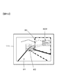
図6(a)は、車両1が走行する道路を例示する図である。図6(a)において、車両1の進行方向に2か所の交差点が設けられている。車両1の現在位置に近い(車両1からの距離d1)交差点を第1の交差点Pとし、車両1の現在位置から遠い(車両1からの距離d2)交差点を第2の交差点Sとする。第1の交差点Pおよび第2の交差点Sには、それぞれ信号機70−1と、信号機70−2とが設けられている。本例では、車両1が第1の交差点Pおよび第2の交差点Sを直進するものとする。 FIG. 6A is a diagram illustrating a road on which the vehicle 1 travels. In FIG. 6A, two intersections are provided in the traveling direction of the vehicle 1. An intersection near the current position of the vehicle 1 (distance d1 from the vehicle 1) is a first intersection P, and an intersection far from the current position of the vehicle 1 (distance d2 from the vehicle 1) is a second intersection S. A traffic signal 70-1 and a traffic signal 70-2 are provided at the first intersection P and the second intersection S, respectively. In this example, it is assumed that the vehicle 1 goes straight through the first intersection P and the second intersection S.

第1の交差点Pには左方から他の車両72が接近し、第2の交差点Sには右方から他の車両73が接近している。また、車両1が進行する道路の高低差は、曲線75のグラフで示される。X軸は車両1の走行距離を表し、Z軸は標高を表す。図6(a)によれば、車両1が走行する道路は、第1の交差点P付近までは上り坂であり、第1の交差点Pを過ぎると第2の交差点Sへ向けて下り坂である。 Another vehicle 72 approaches the first intersection P from the left, and another vehicle 73 approaches the second intersection S from the right. Further, the height difference of the road on which the vehicle 1 travels is shown by a graph of a curve 75. The X axis represents the traveling distance of the vehicle 1, and the Z axis represents the altitude. According to FIG. 6( a ), the road on which the vehicle 1 travels is an uphill up to the vicinity of the first intersection P, and is a downhill toward the second intersection S after passing the first intersection P. ..

図6(b)は、車両1の前方を撮像するカメラ3の撮像素子100に結像される被写体(対象物)の像を模式的に示す図である。図6(b)において、第1の交差点Pにおける対象物(本例では信号機70−1と車両72の前部)を含む領域が注目領域82に設定され、注目領域82を除く領域が準注目領域81に設定される。なお、図6(b)の例では休止領域は設定されていない。 FIG. 6B is a diagram schematically showing an image of a subject (object) formed on the image sensor 100 of the camera 3 that images the front of the vehicle 1. In FIG. 6B, an area including the target object (in this example, the front of the traffic light 70-1 and the vehicle 72) at the first intersection P is set as the attention area 82, and the area excluding the attention area 82 is semi-attention. It is set in the area 81. In addition, in the example of FIG. 6B, the pause area is not set.

車両1の制御装置4は、距離d1があらかじめ設定された距離D(例えば100m)より短かくなると、画像に基づいて認識した対象物を含む注目領域82を設定する。対象物には、移動体として車両や人物が含まれ、非移動体として信号機や横断歩道、遮断機等が含まれる。制御装置4は、注目領域82に対応する撮像素子100の単位領域131(図4)について、以下のように撮像条件を制御する。なお、距離d1は、撮像素子100による測距結果、またはナビゲーション装置18からの地図情報により得ることができる。 When the distance d1 becomes shorter than the preset distance D (for example, 100 m), the control device 4 of the vehicle 1 sets the attention area 82 including the object recognized based on the image. The objects include vehicles and persons as moving bodies, and traffic lights, pedestrian crossings, gates, etc. as non-moving bodies. The control device 4 controls the imaging conditions for the unit area 131 (FIG. 4) of the imaging element 100 corresponding to the attention area 82 as follows. The distance d1 can be obtained from the result of distance measurement by the image sensor 100 or the map information from the navigation device 18.

車両1の制御装置4は、注目領域82に対応する単位領域131に対し、準注目領域81の場合と比べてフレームレートを高くしたり、間引き率を低くしたり、ゲインを上げたりする。間引き率を低くするほど、解像度は高まる。解像度、フレームレートおよびゲインの少なくとも1つを高くすることにより、注目領域82において第1の交差点P付近の詳細な情報が得られるとともに、準注目領域81においては消費電力や発熱を抑えて、効率的な撮像を行わせることができる。 The control device 4 of the vehicle 1 increases the frame rate, lowers the thinning rate, or increases the gain for the unit area 131 corresponding to the attention area 82 as compared with the case of the semi-attention area 81. The lower the thinning rate, the higher the resolution. By increasing at least one of the resolution, the frame rate, and the gain, detailed information near the first intersection P can be obtained in the attention area 82, and power consumption and heat generation can be suppressed in the quasi-attention area 81 to improve efficiency. Imaging can be performed.

ところで、図6(a)によると、第2の交差点Sは第1の交差点Pより標高が低いため、車両1の現在位置からは第2の交差点Sを見通すことができない。このため、たとえ距離d2があらかじめ設定された距離D(例えば100m)より短くなったとしても、第2の交差点S付近の情報を車両1のカメラ3で取得することが困難である。 By the way, according to FIG. 6A, since the second intersection S has a lower altitude than the first intersection P, the second intersection S cannot be seen from the current position of the vehicle 1. Therefore, even if the distance d2 becomes shorter than the preset distance D (for example, 100 m), it is difficult for the camera 3 of the vehicle 1 to acquire the information near the second intersection S.

そこで、車両1の制御装置4は、ナビゲーション装置18からの情報に基づいて、車両1の進行方向の道路に関する情報を解析する。解析には、進行方向の道路の形状についての情報と、第2の交差点Sの三次元位置(緯度、経度、標高)の情報と、対象物(本例では、設置されている信号機70−2)の高さや大きさの情報等を用いる。制御装置4は、解析結果を用いて、第2の交差点Sに設けられている信号機70−2が見え始める車両1の位置を演算する。 Therefore, the control device 4 of the vehicle 1 analyzes the information on the road in the traveling direction of the vehicle 1 based on the information from the navigation device 18. For the analysis, information about the shape of the road in the traveling direction, information about the three-dimensional position (latitude, longitude, altitude) of the second intersection S, and the object (in this example, the installed traffic signal 70-2) are used. ) Height and size information is used. The control device 4 uses the analysis result to calculate the position of the vehicle 1 at which the traffic light 70-2 provided at the second intersection S starts to be seen.

図7(a)は、図6(a)に比べて車両1が進行した状態を例示する図である。図7(a)において、距離d2は、上記距離D(例えば100m)より短い。制御装置4は、車両1の位置が上記演算した位置を通過する手前(例えば30m手前)から、第2の交差点Sにおける信号機70−2が写ると見込まれる撮像素子100の領域を、注目領域82Bとして設定する。図7(b)は、カメラ3の撮像素子100に結像される被写体(対象物)の像を模式的に示す図である。 FIG. 7(a) is a diagram illustrating a state in which the vehicle 1 has advanced compared to FIG. 6(a). In FIG. 7A, the distance d2 is shorter than the distance D (for example, 100 m). The control device 4 sets the area of the image sensor 100 at which the traffic light 70-2 at the second intersection S is expected to appear from the front (for example, 30 m before) where the position of the vehicle 1 passes the calculated position, as the attention area 82B. Set as. FIG. 7B is a diagram schematically showing an image of a subject (object) formed on the image sensor 100 of the camera 3.

図7(b)において、第1の交差点Pにおける信号機70−1および車両72の前部を含む注目領域82と、第2の交差点Sにおける信号機70−2が写ると見込まれる注目領域82Bとが設定され、注目領域82、注目領域82Bを除く領域が準注目領域81に設定される。 In FIG. 7B, an attention area 82 including the traffic light 70-1 and the front part of the vehicle 72 at the first intersection P and an attention area 82B expected to include the traffic light 70-2 at the second intersection S are shown. The areas other than the attention area 82 and the attention area 82B are set as the quasi-attention area 81.

制御装置4は、撮像素子100における注目領域82Bの位置、大きさを、カメラ3の位置から信号機70−2の存在する方向の立体角に対応して決定する。信号機70−2の存在する方向の立体角は、信号機70−2または第2の交差点Sの位置情報、車両1(カメラ3)の位置情報、カメラ3の撮影方向、カメラ3の撮影画角、信号機70−2の高さおよび大きさについての情報から算出する。撮影画角については、撮像光学系31(図4)の設計データに基づく画角情報を用いる。信号機70−2の大きさが不明の場合は、例えば、信号機のサイズとして公知のM型サイズを用いる。また、信号機70−2の高さが不明の場合は、例えば5(m)とする。5(m)は、路面からの所定高さの空間を確保する旨を定めた建築限界に基づく値である。カメラ3の路面からの高さは、本例の場合上述した1.4(m)である。 The control device 4 determines the position and size of the attention area 82B in the image sensor 100 in accordance with the solid angle in the direction in which the traffic light 70-2 exists from the position of the camera 3. The solid angle in the direction in which the traffic light 70-2 exists is the position information of the traffic light 70-2 or the second intersection S, the position information of the vehicle 1 (camera 3), the shooting direction of the camera 3, the shooting angle of view of the camera 3, It is calculated from information about the height and size of the traffic light 70-2. For the shooting angle of view, angle of view information based on design data of the image pickup optical system 31 (FIG. 4) is used. When the size of the traffic light 70-2 is unknown, for example, a known M-type size is used as the size of the traffic light. If the height of the traffic light 70-2 is unknown, the height is, for example, 5 (m). 5 (m) is a value based on the building limit that establishes a space of a predetermined height above the road surface. The height of the camera 3 from the road surface is 1.4 (m) described above in this example.

なお、制御装置4は、車両1が、上記演算した位置(第2の交差点Sの信号機70−2が見え始める位置)の手前30(m)に達する前でも、第2の交差点までの距離d2があらかじめ設定された距離Dより短くなったときから、信号機70−2の存在する方向の立体角に対応して、撮像素子100に注目領域82Bを設定してもよい。
また、制御装置4は、信号機70−2に限らず、第2の交差点Sにおける設置物、建造物、あるいは第2の交差点S全体を含む方向の立体角に基づく注目領域82Bを、撮像素子100に設定してもよい。
Note that the control device 4 controls the distance d2 to the second intersection even before the vehicle 1 reaches 30 (m) before the calculated position (the position at which the traffic light 70-2 at the second intersection S starts to be seen). The area of interest 82B may be set in the image sensor 100 in accordance with the solid angle in the direction in which the traffic light 70-2 is present, from when the distance becomes shorter than the preset distance D.
In addition, the control device 4 is not limited to the traffic light 70-2, and the installation area, the building at the second intersection S, or the attention area 82B based on the solid angle in the direction including the entire second intersection S is set to the imaging element 100. It may be set to.

図7(b)によれば、信号機70−2が写ると見込まれる方向にあらかじめ注目領域82Bを設定しているため、制御装置4は、車両1が第2の交差点Sを見通せる位置へ到達して信号機70−2の像が撮像素子100に写り始める時から、適切に信号機70−2を認識することができる。
制御装置4は、注目領域82Bおよびこの周囲において実際に取得した画像に基づき、必要に応じて注目領域82Bの位置や大きさ(範囲)および撮像条件を変更してよい。具体的には、画像から信号機70−2以外の横断者や自転車が認識される場合には、これらの横断者、自転車および信号機70−2を含む領域を注目領域82として、従前の注目領域82Bに代えて設定する。
According to FIG. 7(b), since the attention area 82B is set in advance in the direction in which the traffic light 70-2 is expected to appear, the control device 4 reaches the position where the vehicle 1 can see the second intersection S. The image of the traffic light 70-2 can be properly recognized from the time when the image of the traffic light 70-2 begins to appear on the image sensor 100.
The control device 4 may change the position, size (range), and imaging condition of the attention area 82B as necessary, based on the image actually acquired in the attention area 82B and the surrounding area. Specifically, when a pedestrian or a bicycle other than the traffic light 70-2 is recognized from the image, the area including the pedestrian, the bicycle, and the traffic light 70-2 is set as the attention area 82, and the previous attention area 82B. Set instead of.

なお、車両1の自動走行制御が解除されている場合(マニュアル運転されている場合)で、かつ車両1が第1の交差点Pに十分に近づいたとき(例えば25m以内)は、車両1の運転者が第1の交差点Pに進入する他の車両72に十分注意するから、制御装置4は、図7(b)の第1の交差点Pについての注目領域82の設定を解除してもよい。 In addition, when the automatic traveling control of the vehicle 1 is released (when the vehicle 1 is manually driven) and when the vehicle 1 is sufficiently close to the first intersection P (for example, within 25 m), the driving of the vehicle 1 is performed. Since the person pays sufficient attention to the other vehicles 72 approaching the first intersection P, the control device 4 may cancel the setting of the attention area 82 for the first intersection P in FIG. 7B.

<フローチャートの説明>
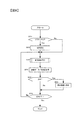
以下、図8および図9のフローチャートを参照して注目領域82、82Bおよび準注目領域81の決め方について説明する。図8は、制御装置4が実行するカメラ3の制御処理の流れを説明するフローチャートである。図8のフローチャートによる処理を実行するためのプログラムは、制御装置4の記憶部4b(図2)に格納されている。制御装置4は、例えば車両1から電源供給が開始されたり、エンジンが始動されたりすると、図8による処理を行うプログラムを起動する。
<Explanation of flow chart>
Hereinafter, how to determine the attention areas 82 and 82B and the semi-attention area 81 will be described with reference to the flowcharts of FIGS. 8 and 9. FIG. 8 is a flowchart illustrating a flow of control processing of the camera 3 executed by the control device 4. A program for executing the process according to the flowchart of FIG. 8 is stored in the storage unit 4b (FIG. 2) of the control device 4. The control device 4 activates a program for performing the process shown in FIG. 8 when the power supply from the vehicle 1 is started or the engine is started, for example.

図8のステップS10において、制御装置4は、フラグaが0か否かを判定する。フラグaは、初期設定が終了している場合に1、初期設定が終了していない場合に0がセットされるフラグである。制御装置4は、フラグa=0の場合にステップS10を肯定判定してステップS20へ進み、フラグa≠0の場合にステップS10を否定判定してステップS30へ進む。 In step S10 of FIG. 8, the control device 4 determines whether the flag a is 0. The flag a is a flag which is set to 1 when the initial setting is completed and is set to 0 when the initial setting is not completed. The controller 4 makes an affirmative decision in step S10 if the flag a=0 to proceed to step S20, whereas it makes a negative decision in step S10 if the flag a≠0 to proceed to step S30.

ステップS20において、制御装置4は、カメラ3へ初期設定を行ってステップS30へと進む。初期設定とは、カメラ3に所定の動作をさせるためにあらかじめ定められた設定を行うものである。これにより、カメラ3が撮像素子100の撮像面の全域に同じ撮像条件を設定し、例えば毎秒60フレーム(60fps)のフレームレートで撮像を開始する。 In step S20, the control device 4 initializes the camera 3 and proceeds to step S30. The initial setting is to perform a preset setting for causing the camera 3 to perform a predetermined operation. As a result, the camera 3 sets the same imaging condition on the entire imaging surface of the image sensor 100, and starts imaging at a frame rate of 60 frames per second (60 fps), for example.

ステップS30において、制御装置4は、撮像条件設定処理を行ってステップS40へ進む。撮像条件設定処理では、注目領域82(必要な場合は注目領域82B)および準注目領域81を設定し、それぞれの領域に対応する単位領域131に対して撮像条件を設定する。撮像条件設定処理の詳細については後述する。 In step S30, the control device 4 performs an imaging condition setting process and proceeds to step S40. In the imaging condition setting process, the attention area 82 (the attention area 82B if necessary) and the quasi-attention area 81 are set, and the imaging condition is set for the unit area 131 corresponding to each area. Details of the imaging condition setting processing will be described later.

ステップS40において、制御装置4はカメラ3へ指示を送り、注目領域82(注目領域82B)および準注目領域81に対応する撮像素子100の単位領域131をそれぞれ所定の条件で駆動させて、画像の取得および測距演算を行わせる。これにより、画像データや測距情報が取得される。また、制御装置4は、カメラ3の画像処理部33または制御部35等に所定の画像処理および画像解析を行わせる。 In step S40, the control device 4 sends an instruction to the camera 3 to drive the unit areas 131 of the image pickup device 100 corresponding to the attention area 82 (attention area 82B) and the quasi-attention area 81 under predetermined conditions, respectively. Perform acquisition and ranging calculations. As a result, image data and distance measurement information are acquired. The control device 4 also causes the image processing unit 33, the control unit 35, or the like of the camera 3 to perform predetermined image processing and image analysis.

ステップS50において、制御装置4は、情報を表示する設定が行われているか否かを判定する。制御装置4は、表示設定が行われている場合にステップ50を肯定判定してステップS60へ進む。制御装置4は、表示設定が行われていない場合には、ステップS50を否定判定してステップS70へ進む。 In step S50, the control device 4 determines whether or not the setting for displaying information is made. The control device 4 makes an affirmative decision in step 50 if the display settings have been made to proceed to step S60. When the display setting is not performed, the control device 4 makes a negative determination in step S50 and proceeds to step S70.

ステップS60において、制御装置4は、表示装置14またはナビゲーション装置18(図1)に対する表示情報を送出してステップS70へ進む。表示情報は、撮像条件設定処理(S30)の中で判断された車両1の状態または進行方向の道路に関する情報で、例えば「1km先に工事区間があります」「車両が接近しています」、「緊急停車します」、「右折します」というメッセージを表示装置14またはナビゲーション装置18に表示させる。
なお、表示情報を送出する代わりに、または表示情報の送出とともに、不図示の音声再生装置へ上記メッセージを再生させるための音声信号を送出してもよい。この場合、音声再生装置として、ナビゲーション装置18の音声再生部を用いてもよい。
In step S60, the control device 4 sends the display information for the display device 14 or the navigation device 18 (FIG. 1), and proceeds to step S70. The display information is information about the state of the vehicle 1 or the road in the traveling direction determined in the imaging condition setting process (S30), for example, "there is a construction section 1 km ahead", "the vehicle is approaching", " The messages "Immediate stop" and "Turn right" are displayed on the display device 14 or the navigation device 18.
Instead of transmitting the display information or together with the display information, an audio signal for reproducing the message may be transmitted to an audio reproducing device (not shown). In this case, the audio reproduction unit of the navigation device 18 may be used as the audio reproduction device.

ステップS70において、制御装置4は、オフ操作されたか否かを判定する。制御装置4は、例えば車両1からオフ信号(例えば、エンジンのオフ信号)を受けると、ステップS70を肯定判定し、所定のオフ処理を行って図8による処理を終了する。制御装置4は、例えば車両1からオフ信号を受けない場合は、ステップS70を否定判定してステップS30へ戻る。ステップS30へ戻る場合は、上述した処理を繰り返す。 In step S70, the control device 4 determines whether the off operation has been performed. For example, when the control device 4 receives an off signal (for example, an engine off signal) from the vehicle 1, the control device 4 makes an affirmative decision in step S70, performs a predetermined off process, and ends the process in FIG. For example, when the off signal is not received from the vehicle 1, the control device 4 makes a negative determination in step S70 and returns to step S30. When returning to step S30, the above-mentioned processing is repeated.

<撮像条件設定処理>
図9のフローチャートを参照して、上記撮像条件設定処理(ステップS30)の詳細について説明する。本実施の形態では、ナビゲーション装置18等から取得した車両1の位置に関する情報に基づき、また、車両1の走行環境(道路状況や撮影環境)の変化に対応させて、注目領域82、注目領域82Bおよび準注目領域81にそれぞれ対応する撮像素子100の単位領域131に対して撮像条件を設定する。
<Imaging condition setting process>
Details of the imaging condition setting process (step S30) will be described with reference to the flowchart of FIG. In the present embodiment, the attention area 82 and the attention area 82B are based on the information about the position of the vehicle 1 acquired from the navigation device 18 and the like, and in association with the change of the traveling environment (road condition or photographing environment) of the vehicle 1. And the imaging conditions are set for the unit areas 131 of the image sensor 100 corresponding to the semi-target area 81.

ステップS31において、制御装置4は、ナビゲーション装置18等から情報を取得する。取得する情報には、車両1の進行方向に位置する交差点等(交差点、踏切、バス停留所等)における対象物(車両、信号機、横断歩道、遮断機、警報機、建造物等)の位置、大きさ、高さについての情報と、車両1の位置情報と、道路の形状、高低差、遮蔽物等の情報等とが含まれる。 In step S31, the control device 4 acquires information from the navigation device 18 or the like. The information to be acquired includes the position and size of objects (vehicles, traffic lights, pedestrian crossings, gates, alarms, buildings, etc.) at intersections (intersections, railroad crossings, bus stops, etc.) located in the traveling direction of the vehicle 1. Information about the height and height, the position information of the vehicle 1, the shape of the road, the height difference, the obstacles, and the like are included.

ステップS33において、制御装置4は、車両1の現在位置から対象物までの距離dが、上記所定の距離Dより短いか否かを判定する。制御装置4は、距離dが距離Dより短い場合に、ステップS33を肯定判定してステップS35に進む。制御装置4は、距離dが距離Dより短くない場合には、ステップS33を否定判定してステップS31へ戻る。ステップS31へ戻る場合は、注目すべき対象物が車両1の近くに存在しない場合である。ステップS31へ戻った制御装置4は、ステップS20の場合と同様に、撮像素子100の撮像面の全域で共通の撮像条件を採用する。 In step S33, the control device 4 determines whether or not the distance d from the current position of the vehicle 1 to the object is shorter than the predetermined distance D. When the distance d is shorter than the distance D, the control device 4 makes an affirmative decision in step S33 and the operation proceeds to step S35. When the distance d is not shorter than the distance D, the control device 4 makes a negative determination in step S33 and returns to step S31. The case of returning to step S31 is a case where the target object to be noticed does not exist near the vehicle 1. The control device 4, which has returned to step S31, adopts the common imaging condition over the entire imaging surface of the imaging device 100, as in the case of step S20.

ステップS35において、制御装置4は、対象物を光学的に(例えば視覚情報として)認識できるか否かを判定する。制御装置4は、例えば、撮像素子100により撮像された画像から対象物の外形的特徴や、対象物に付された識別情報(識別コードやマーク等)を検出することにより、対象物の認識を行う。制御装置4は、対象物の外形的特徴を検出、または対象物の識別情報を検出した場合に対象物を光学的に認識できると判断し、ステップS35を肯定判定してステップS37へ進む。制御装置4は、対象物の外形的特徴も識別情報も検出しない場合には、対象物を光学的に認識できないと判断し、ステップS35を否定判定してステップS351へ進む。 In step S35, the control device 4 determines whether the object can be optically recognized (for example, as visual information). The control device 4 recognizes the target object by detecting the external characteristics of the target object and the identification information (identification code, mark, etc.) attached to the target object from the image captured by the image sensor 100, for example. To do. The control device 4 determines that the target object can be optically recognized when the external characteristic of the target object is detected, or when the identification information of the target object is detected, the control device 4 makes an affirmative decision in step S35, and proceeds to step S37. When neither the external characteristic of the object nor the identification information is detected, the control device 4 determines that the object cannot be optically recognized, makes a negative determination in step S35, and proceeds to step S351.

ステップS37において、制御装置4は、認識した対象物を含む範囲を注目領域82として設定し、ステップS39へ進む。なお、注目領域82の範囲は、必ずしも対象物を包含する大きさでなくてもよい。 In step S37, the control device 4 sets the range including the recognized target object as the attention area 82, and proceeds to step S39. The range of the attention area 82 does not necessarily have to be a size including the target object.

ステップS39において、制御装置4は、注目領域82および準注目領域81に対応する撮像素子100の単位領域131に対して、それぞれ撮像条件を設定する。制御装置4は、例えば、車両1の移動速度が速いほど、道路の曲率が大きいほど、注目領域82に該当する撮像素子100の単位領域131のフレームレートを高く設定し(例えば120fps)、間引き率を0〜20%とする。反対に、車両1の移動速度が遅いほど、道路の曲率が小さいほど、準注目領域81に該当する撮像素子100の単位領域131のフレームレートを低く設定し(例えば30fps)、間引き率を30〜60%とする。 In step S39, the control device 4 sets the imaging conditions for the unit areas 131 of the image sensor 100 corresponding to the attention area 82 and the semi-attention area 81, respectively. For example, the control device 4 sets the frame rate of the unit area 131 of the image sensor 100 corresponding to the attention area 82 to be higher (for example, 120 fps) as the moving speed of the vehicle 1 is higher and the curvature of the road is larger, and the thinning rate is set. Is 0 to 20%. On the contrary, the slower the moving speed of the vehicle 1 and the smaller the curvature of the road, the lower the frame rate of the unit area 131 of the image sensor 100 corresponding to the quasi-attention area 81 (for example, 30 fps), and the thinning rate of 30 to 60%.

このように、ナビゲーション装置18等から取得した車両1の位置に関する情報に基づき、車両1の走行環境(道路状況)に対応させて、撮像素子100の撮像条件を設定する。撮像条件には、フレームレートや間引き率の他に、ゲインや画素信号加算時の加算行数または加算列数、電荷の蓄積時間または蓄積回数、デジタル化のビット数等を含めてもよい。蓄積時間は、露光時間に相当する。画素信号加算時の加算行数や加算列数を増やすと、解像度は低下する。 As described above, based on the information about the position of the vehicle 1 acquired from the navigation device 18 or the like, the image capturing condition of the image sensor 100 is set according to the traveling environment (road condition) of the vehicle 1. The imaging conditions may include, in addition to the frame rate and the thinning rate, a gain, the number of addition rows or columns when adding pixel signals, the charge accumulation time or number, the number of digitized bits, and the like. The accumulation time corresponds to the exposure time. If the number of added rows or the number of added columns at the time of adding pixel signals is increased, the resolution is lowered.

また、制御装置4は、対象物の特性(例えば、対象物の輝度が高いか低いか等)に対応させて、撮像素子100の撮像条件を設定する。例えば、対象物が高輝度の場合は、対象物が低輝度の場合に比べて露光時間を短く設定したり、低ゲインに設定したりする。 Further, the control device 4 sets the imaging condition of the imaging element 100 in correspondence with the characteristics of the target object (for example, whether the target object has high brightness or low brightness). For example, when the object has high brightness, the exposure time is set shorter or the gain is set lower than when the object has low brightness.

さらにまた、制御装置4は、撮影環境に応じて撮像条件の設定を適宜調節してもよい。例えば、夜間走行の場合や、昼間におけるトンネルの出入り口を走行する場合、画面の暗部において画面の明部よりも高ゲインに設定したり、露光時間を長く設定したりする。画面の明部と暗部とで差をつけるのは、画面の暗部において黒つぶれを抑えるとともに、画面の明部において白とびを防ぐためである。 Furthermore, the control device 4 may appropriately adjust the setting of the imaging condition according to the imaging environment. For example, when traveling at night or when traveling through the entrance/exit of a tunnel in the daytime, the dark part of the screen is set to have a higher gain than the bright part of the screen, or the exposure time is set to be long. The difference between the bright part and the dark part of the screen is set in order to suppress blackout in the dark part of the screen and to prevent blown-out highlights in the bright part of the screen.

上述したステップS35を否定判定して進むステップS351において、制御装置4は、対象物を光学的に(例えば視覚情報として)認識できる位置へ車両1が到達したか否かを判定する。制御装置4は、進行方向の道路の形状と、交差点等の三次元位置(緯度、経度、標高)と、対象物の高さや大きさとに基づく上記解析結果を用いて演算した位置(すなわち、対象物が見え始める位置)へ車両1が到達した場合、ステップS351を肯定判定してステップS353へ進む。制御装置4は、対象物が見え始める位置へ車両1が到達していない場合には、ステップS351を否定判定して当該判定処理を繰り返す。 In step S351 that proceeds after making a negative decision in step S35 described above, the control device 4 determines whether or not the vehicle 1 has reached a position where the object can be optically recognized (for example, as visual information). The control device 4 calculates the position based on the shape of the road in the traveling direction, the three-dimensional position (latitude, longitude, altitude) such as an intersection, and the analysis result based on the height and size of the target (that is, the target). When the vehicle 1 reaches the position (at which the object starts to be seen), the affirmative decision is made in step S351 and the operation proceeds to step S353. When the vehicle 1 has not reached the position where the object starts to be seen, the control device 4 makes a negative determination in step S351 and repeats the determination process.

ここで、対象物を光学的に認識できる位置までの距離を、直線距離でなく、地図上の道路に沿った経路上の距離にすることが好ましい。車両1から対象物を光学的に認識できる位置までの距離が、あらかじめ設定されている所定の距離Dより短くない場合は、ステップ351を否定判定する。 Here, it is preferable that the distance to the position where the object can be optically recognized is not a linear distance but a distance on a route along a road on the map. When the distance from the vehicle 1 to the position where the object can be optically recognized is not shorter than the preset predetermined distance D, negative determination is made in step 351.

ステップS353において、制御装置4は、上述したように、対象物(本例では信号機70−2)の方向の立体角に対応して注目領域82Bを設定し、ステップS355へ進む。すなわち、注目領域82Bの位置および大きさを、カメラ3の位置から対象物の存在する方向の立体角に対応して決定する。対象物が存在する方向の立体角は、カメラ3と対象物との位置関係、対象物の情報(対象物が設置されている路面からの高さ、対象物の一般的な大きさ等)に基づいて算出する。 In step S353, the control device 4 sets the attention area 82B corresponding to the solid angle in the direction of the object (the traffic signal 70-2 in this example), as described above, and proceeds to step S355. That is, the position and size of the attention area 82B are determined corresponding to the solid angle in the direction in which the object exists from the position of the camera 3. The solid angle in the direction in which the object exists is determined by the positional relationship between the camera 3 and the object, information on the object (height from the road surface on which the object is installed, general size of the object, etc.). Calculate based on

ステップS355において、制御装置4は、注目領域82Bおよび準注目領域81に対応する撮像素子100の単位領域131に対して、それぞれ撮像条件を設定する。撮像条件の決め方は、ステップS39の場合と同様である。 In step S355, the control device 4 sets the imaging conditions for each of the unit areas 131 of the image sensor 100 corresponding to the attention area 82B and the semi-attention area 81. The method of determining the imaging condition is the same as that in step S39.

ステップS357において、制御装置4は、ステップS35の場合と同様に、対象物を光学的に(例えば視覚情報として)認識できるか否かを判定する。制御装置4は、対象物の外形的特徴を検出、または対象物の識別情報を検出した場合に対象物を光学的に認識できると判断し、ステップS357を肯定判定してステップS37へ進む。ステップS37へ進むと、制御装置4は、取得された画像から認識した対象物を含む範囲を注目領域82として設定し直す。例えば、図7(a)に示す車両73を認識した場合には、車両73および信号機70−2を含む領域を注目領域82として、従前の注目領域82Bに代えて設定する。
なお、制御装置4は、ステップS357を肯定判定した場合に、従前の注目領域82Bに車両73および信号機70−2を含む領域を加えた領域を注目領域82として設定し直してもよい。
In step S357, the control device 4 determines whether or not the object can be optically recognized (as visual information, for example), as in the case of step S35. The control device 4 determines that the target object can be optically recognized when the external characteristic of the target object is detected, or when the identification information of the target object is detected, the control device 4 makes a positive determination in step S357 and proceeds to step S37. When proceeding to step S37, the control device 4 resets the range including the object recognized from the acquired image as the attention area 82. For example, when the vehicle 73 shown in FIG. 7A is recognized, the area including the vehicle 73 and the traffic light 70-2 is set as the attention area 82 instead of the previous attention area 82B.
When the determination in step S357 is affirmative, the control device 4 may reset an area in which the area including the vehicle 73 and the traffic light 70-2 is added to the area of interest 82B in the past as the area of interest 82.

一方、制御装置4は、ステップS357において対象物の外形的特徴も識別情報も検出しない場合には、対象物を光学的に認識できないと判断し、ステップS357を否定判定してステップS351へ戻る。ステップS351へ戻る場合は、上述した処理を繰り返す。 On the other hand, the control device 4 determines that the target object cannot be optically recognized when neither the external characteristic of the target object nor the identification information is detected in step S357, and the process returns to step S351 by making a negative determination in step S357. When returning to step S351, the above-described processing is repeated.

以上説明した第一の実施の形態によれば、次の作用効果が得られる。
(1)撮像装置は、複数の単位領域131の撮像条件を独立して設定可能な撮像素子100を備えた撮像部32と、車両1の位置に関する情報に基づいて、複数の単位領域131の撮像条件を設定する制御装置4とを備えたので、撮像素子100の単位領域131ごとに適切な撮像条件を設定できる。
According to the first embodiment described above, the following operational effects can be obtained.
(1) The image capturing apparatus captures an image of a plurality of unit areas 131 based on information about the position of the vehicle 1 and the image capturing unit 32 including the image sensor 100 that can independently set the image capturing conditions of the plurality of unit areas 131. Since the control device 4 for setting the conditions is provided, it is possible to set an appropriate imaging condition for each unit area 131 of the imaging element 100.

(2)撮像装置は、車両1の位置に関する情報をナビゲーション装置18から取得する制御装置4を備えたので、例えば、ナビゲーション装置18で探索された走行経路の情報を用いて、撮像素子100の単位領域131ごとに適切な撮像条件を設定できる。 (2) Since the imaging device includes the control device 4 that acquires information about the position of the vehicle 1 from the navigation device 18, for example, using the information about the travel route searched by the navigation device 18, the unit of the imaging device 100 Appropriate imaging conditions can be set for each region 131.

(3)制御装置4は、車両1の進行方向の道路に関する情報を車両1の位置に関する情報として取得するので、例えば、車両1の進行方向に位置する交差点等を撮像する撮像素子100の単位領域131に対して、適切な撮像条件を設定できる。 (3) Since the control device 4 obtains the information about the road in the traveling direction of the vehicle 1 as the information about the position of the vehicle 1, for example, the unit area of the image sensor 100 that images an intersection or the like located in the traveling direction of the vehicle 1. Appropriate imaging conditions can be set for 131.

(4)制御装置4は、撮像部32のフレームレート、露光時間、ゲイン、解像度(画素間引き条件、画素加算条件)、注目領域82Bのサイズ、および注目領域82Bの位置の少なくとも1つを撮像条件として設定するので、例えば注目領域82Bに対応する撮像素子100の単位領域131に適切な撮像条件を設定できる。 (4) The control device 4 sets at least one of the frame rate, the exposure time, the gain, the resolution (pixel thinning condition, pixel addition condition), the size of the attention area 82B, and the position of the attention area 82B of the imaging unit 32 as the imaging condition. Therefore, it is possible to set an appropriate imaging condition in the unit area 131 of the imaging element 100 corresponding to the attention area 82B, for example.

(5)制御装置4は、車両1の進行方向の道路に関する情報として交差点に関する情報を取得するとともに、複数の単位領域131のうち交差点が写る注目領域82Bについて、解像度、ゲイン、フレームレートのうち少なくとも1つを準注目領域81と異ならせる。これにより、注目領域82Bにおいて交差点付近の詳細な情報が得られるとともに、準注目領域81においては消費電力や発熱を抑えることができる。 (5) The control device 4 acquires the information about the intersection as the information about the road in the traveling direction of the vehicle 1, and at least the resolution, the gain, and the frame rate of the attention area 82B in which the intersection is shown among the plurality of unit areas 131. One is made different from the quasi-attention area 81. As a result, detailed information near the intersection can be obtained in the attention area 82B, and power consumption and heat generation can be suppressed in the semi-attention area 81.

(6)制御装置4は、解像度とゲインとフレームレートのうち少なくとも1つを準注目領域81よりも高くするので、注目領域82Bにおいて準注目領域81より詳細な情報が得られるとともに、準注目領域81においては消費電力や発熱を抑えることができる。 (6) Since the control device 4 sets at least one of the resolution, the gain, and the frame rate higher than that of the quasi-attention region 81, detailed information can be obtained in the observing region 82B from the quasi-attention region 81 and the quasi-attention region can be obtained. In 81, power consumption and heat generation can be suppressed.

(7)制御装置4は、車両1の運転状況を併用して、注目領域82Bの撮像条件を設定する。例えば車両1の移動速度が速いほど、注目領域82Bのフレームレートを高く設定することで、注目領域82Bにおいて準注目領域81より詳細な情報が得られる。 (7) The control device 4 sets the imaging condition of the attention area 82B by also using the driving condition of the vehicle 1. For example, by setting the frame rate of the attention area 82B to be higher as the moving speed of the vehicle 1 is higher, more detailed information can be obtained in the attention area 82B than in the semi-attention area 81.

(8)制御装置4は、車両1の位置に関する情報として、車両1の進行方向に位置する信号機70−2の高さおよび大きさ、および車両1と信号機70−2との位置関係を示す情報(信号機70−2の位置、カメラ3の位置、カメラ3の高さ、カメラ3の撮影方向)をそれぞれ取得し、取得した情報に基づいて、信号機70−2が写ると見込まれる撮像素子100における注目領域82Bを算出し、さらに、算出した注目領域82Bについて、準注目領域81と異なる撮像条件を設定するようにした。これにより、車両1が信号機70−2を見通せる位置へ到達する前から、信号機70−2が写ると見込まれる注目領域82Bに対して事前に適切な撮像条件を設定しておくことができる。
なお、上述した実施の形態では、制御装置4の制御によりカメラ3を制御したが、カメラ3の制御の一部をカメラ3の制御部35により行うようにしてもよい。
(8) The control device 4, as the information on the position of the vehicle 1, information indicating the height and size of the traffic signal 70-2 located in the traveling direction of the vehicle 1, and the positional relationship between the vehicle 1 and the traffic signal 70-2. (The position of the traffic light 70-2, the position of the camera 3, the height of the camera 3, the shooting direction of the camera 3) are respectively acquired, and based on the acquired information, in the image sensor 100 that is expected to capture the traffic light 70-2. The attention area 82B is calculated, and an imaging condition different from that of the semi-attention area 81 is set for the calculated attention area 82B. As a result, before the vehicle 1 reaches the position where the traffic light 70-2 can be seen through, it is possible to set appropriate imaging conditions in advance for the attention area 82B where the traffic light 70-2 is expected to appear.
Although the camera 3 is controlled by the control of the control device 4 in the above-described embodiment, a part of the control of the camera 3 may be performed by the control unit 35 of the camera 3.

次のような変形も本発明の範囲内であり、変形例の一つ、若しくは複数を上述の実施の形態と組み合わせることも可能である。
(変形例1)
撮像条件設定処理(図9)のステップS351において、車両1が、対象物を光学的に認識できる位置まで到達したか否かを判定する例を説明したが、車両1が、対象物を光学的に認識できる位置まで所定の時間内で到達できるか否かを判定するようにしてもよい。制御装置4は、例えば、車両1の現在位置から、上記対象物を光学的に認識できる位置までの距離を、車両1の車速V、あるいは走行中の一定時間内の平均車速等で除算することにより、上記所定の時間を算出する。これにより、車両1の移動速度を考慮し、撮像素子100の単位領域131に対して適切な撮像条件を設定することができる。
The following modifications are also within the scope of the present invention, and one or a plurality of modifications can be combined with the above-described embodiment.
(Modification 1)
In step S351 of the imaging condition setting process (FIG. 9), the example in which the vehicle 1 determines whether or not it has reached a position where the object can be optically recognized has been described. Alternatively, it may be determined whether or not a position that can be recognized can be reached within a predetermined time. The control device 4 divides, for example, the distance from the current position of the vehicle 1 to a position where the object can be optically recognized by the vehicle speed V of the vehicle 1 or the average vehicle speed within a certain time during traveling. Then, the above-mentioned predetermined time is calculated. Thereby, it is possible to set an appropriate imaging condition for the unit area 131 of the imaging device 100 in consideration of the moving speed of the vehicle 1.

(変形例2)
撮像条件設定処理(図9)において、制御装置4は、進行方向の道路に存在する対象物に対して注目領域82を設定し、または対象物の存在する方向に注目領域82Bを設定するようにした。対象物は、車両1の進行方向に存在していればよく、ナビゲーション装置18による案内中の走行経路上に対象物が存在していなくてもよかった。これに対し、変形例2における制御装置4は、ナビゲーション装置18の経路探索機能によって導出されたルート上にある設置物等のみを対象物としてステップS31以降の処理を行う。これにより、制御装置4は、走行経路上にない対象物については、対象物の位置、高さ、大きさについての情報を取得しなくてよいので、通信負荷や情報処理等の負荷を減らしつつ、撮像素子100の単位領域131に対して適切な撮像条件を設定することができる。
(Modification 2)
In the imaging condition setting process (FIG. 9), the control device 4 sets the attention area 82 for the target object existing on the road in the traveling direction, or sets the attention area 82B in the direction where the target object exists. did. It suffices that the target object exists in the traveling direction of the vehicle 1, and the target object does not have to exist on the traveling route being guided by the navigation device 18. On the other hand, the control device 4 in the modified example 2 performs the processes from step S31 onward with only the installation object or the like on the route derived by the route search function of the navigation device 18 as the target. As a result, the control device 4 does not have to acquire information about the position, height, and size of the target object that is not on the travel route, thus reducing the communication load and the information processing load. It is possible to set appropriate imaging conditions for the unit area 131 of the imaging device 100.

(変形例3)
撮像条件設定処理(図9)において、制御装置4は、対象物を、走行する道路のカーブや、道路幅の変化(幅員減少、走行レーン数の減少)地点等の道路の形状としてもよい。図10は、山道等のカーブが多い道路を走行する車両1のカメラ3の撮像素子100に結像される被写体(対象物)の像を模式的に示す図である。
(Modification 3)
In the imaging condition setting process (FIG. 9), the control device 4 may set the object to be a shape of a road such as a curve of a road on which the vehicle travels or a point where the width of the road changes (width decreases, the number of traveling lanes decreases). FIG. 10 is a diagram schematically showing an image of a subject (object) formed on the image sensor 100 of the camera 3 of the vehicle 1 traveling on a road with many curves such as a mountain road.

制御装置4は、ナビゲーション装置18から、進行方向の道路の情報としてカーブの有無、カーブの方向、カーブの曲率等のカーブに関する情報を取得する。取得した情報によると、車両1が進む道路の前方には、右へ曲がるカーブが存在する。右カーブの先にはさらに、左へ曲がるカーブが存在する。ところが、道路の右側に設けられた遮蔽物90の存在により、カメラ3で取得される画像には左カーブが写らない。 The control device 4 acquires from the navigation device 18 information about a curve such as the presence/absence of a curve, the direction of the curve, the curvature of the curve, etc. as information about the road in the traveling direction. According to the acquired information, there is a curve turning to the right in front of the road on which the vehicle 1 travels. At the end of the right curve, there is another curve that turns to the left. However, due to the presence of the shield 90 provided on the right side of the road, the left curve is not reflected in the image acquired by the camera 3.

この場合において、制御装置4は、右カーブが写る領域を注目領域82として設定するとともに、遮蔽物90の陰に入って光学的に認識できない左カーブについては、この左カーブが写ると見込まれる領域を注目領域82Bとして設定する。制御装置4は、上述したように、左カーブが存在する方向の立体角に対応して注目領域82Bを設定する。すなわち、注目領域82Bの位置および大きさを、カメラ3の位置から左カーブの存在する方向の立体角に対応して決定する。立体角は、カメラ3と左カーブとの位置関係、左カーブの情報(標高、道路の規格等)に基づいて算出する。 In this case, the control device 4 sets the area in which the right curve is reflected as the attention area 82, and the left curve which is in the shadow of the shield 90 and cannot be optically recognized is expected to include this left curve. Is set as the attention area 82B. As described above, the control device 4 sets the attention area 82B in correspondence with the solid angle in the direction in which the left curve exists. That is, the position and size of the attention area 82B are determined corresponding to the solid angle in the direction in which the left curve exists from the position of the camera 3. The solid angle is calculated based on the positional relationship between the camera 3 and the left curve, and information on the left curve (elevation, road standard, etc.).

制御装置4は、注目領域82、注目領域82Bに対応する撮像素子100の単位領域131に対して、それぞれ撮像条件を設定する。変形例3によれば、例えば防音壁や暴風壁などの遮蔽物90が存在する道路でも、左カーブ(対象物)が遮蔽物90の陰から出現する前から、左カーブ(対象物)が写ると見込まれる注目領域82Bに対して事前に適切な撮像条件を設定しておくことができる。また、左カーブ(対象物)に対する注目領域82Bの位置、範囲の決定に関しては、当該カーブの曲率が最大になる地点の位置に決定したり、当該カーブの曲り始めの地点の曲率を基に範囲を決定したりするなど、道路幅等の道路の規格に基づいて得られる左カーブ(対象物)の大きさから、適切な注目領域82Bの位置、範囲を決定することができる。
なお、遮蔽物90は、車両1から対象物の光学的な(例えば視覚情報として)認識を遮るものであり、上述した防音壁や暴風壁だけでなく、広告や看板、建造物や樹木、大型車両、地形の起伏等を含む。
The control device 4 sets the imaging conditions for the unit area 131 of the image sensor 100 corresponding to the attention area 82 and the attention area 82B, respectively. According to the modified example 3, even on a road having a shield 90 such as a soundproof wall or a storm wall, the left curve (target) appears before the left curve (target) appears from behind the shield 90. Appropriate imaging conditions can be set in advance for the attention area 82B expected to be. Further, regarding the position and range of the attention area 82B with respect to the left curve (object), the range is determined based on the position of the point where the curvature of the curve is maximized or the curvature of the starting point of the curve. It is possible to determine the appropriate position and range of the attention area 82B from the size of the left curve (object) obtained based on the road standard such as the road width.
The shield 90 shields the optical recognition of the object from the vehicle 1 (for example, as visual information), and is not limited to the soundproof wall and the windstorm wall described above, but also advertisements, signboards, buildings and trees, large size Includes rolling terrain and vehicles.

変形例3によれば、制御装置4は、カーブに関する情報を車両1の進行方向の道路に関する情報として取得するとともに、複数の単位領域131のうちカーブが写る注目領域82Bについて、解像度とゲインとフレームレートのうち少なくとも1つを準注目領域81と異ならせる。これにより、注目領域82Bにおいてカーブ付近の詳細な情報が得られるとともに、準注目領域81においては消費電力や発熱を抑えることができる。 According to the modified example 3, the control device 4 obtains the information about the curve as the information about the road in the traveling direction of the vehicle 1, and the resolution, the gain, and the frame of the attention area 82B in which the curve appears among the plurality of unit areas 131. At least one of the rates is different from the quasi-attention area 81. As a result, detailed information near the curve can be obtained in the attention area 82B, and power consumption and heat generation can be suppressed in the semi-attention area 81.

また、制御装置4は、道路幅の変化の情報を車両1の進行方向の道路に関する情報として取得するとともに、複数の単位領域131のうち道路幅の変化する区間が写る注目領域82Bについて、解像度とゲインとフレームレートのうち少なくとも1つを準注目領域81と異ならせる。これにより、注目領域82Bにおいて道路幅変化の詳細な情報が得られるとともに、準注目領域81においては消費電力や発熱を抑えることができる。 Further, the control device 4 acquires the information about the change in the road width as the information about the road in the traveling direction of the vehicle 1, and determines the resolution of the attention area 82B in which the section where the road width changes among the plurality of unit areas 131 appears. At least one of the gain and the frame rate is made different from the quasi-attention region 81. As a result, detailed information on the road width change can be obtained in the attention area 82B, and power consumption and heat generation can be suppressed in the semi-attention area 81.

(変形例4)
撮像条件設定処理(図9)において、制御装置4は、トンネルの入口、出口を対象物としてもよい。トンネルの内部はトンネルの外部より暗いため、トンネルの入口を対象物とするときは、トンネルの内部が写ると見込まれる領域を注目領域82Bとし、注目領域82Bに対応する撮像素子100の単位領域131のゲインを、トンネルの外部である準注目領域81に対応する単位領域131のゲインより高くする。なお、ゲインを変える代わりに注目領域82Bに対応する撮像素子100の単位領域131の露光時間を、トンネルの外部である準注目領域81に対応する単位領域131の露光時間より長くしてもよい。
(Modification 4)
In the imaging condition setting process (FIG. 9), the control device 4 may set the entrance and exit of the tunnel as the target. Since the inside of the tunnel is darker than the outside of the tunnel, when the entrance of the tunnel is an object, the area expected to show the inside of the tunnel is the attention area 82B, and the unit area 131 of the image sensor 100 corresponding to the attention area 82B. Is made higher than the gain of the unit area 131 corresponding to the quasi-attention area 81 outside the tunnel. Instead of changing the gain, the exposure time of the unit area 131 of the image sensor 100 corresponding to the attention area 82B may be set longer than the exposure time of the unit area 131 corresponding to the semi-attention area 81 outside the tunnel.

同様に、トンネルの出口では、トンネルの外部が写ると見込まれる領域を注目領域82Bとし、注目領域82Bに対応する撮像素子100の単位領域131のゲインを、トンネルの内部である準注目領域81に対応する単位領域131のゲインより低くする。これにより、対象物の明暗の程度に応じ、撮像素子100の単位領域131に対して適切な撮像条件を設定することができる。なお、ゲインを変える代わりに注目領域82Bに対応する撮像素子100の単位領域131の露光時間を、トンネルの内部である準注目領域81に対応する単位領域131の露光時間より短くしてもよい。 Similarly, at the exit of the tunnel, a region where the outside of the tunnel is expected to be seen is the attention region 82B, and the gain of the unit region 131 of the image sensor 100 corresponding to the attention region 82B is set to the quasi-attention region 81 inside the tunnel. The gain is set lower than that of the corresponding unit area 131. Accordingly, it is possible to set an appropriate imaging condition for the unit area 131 of the imaging device 100 according to the degree of brightness of the object. Instead of changing the gain, the exposure time of the unit area 131 of the image sensor 100 corresponding to the attention area 82B may be set shorter than the exposure time of the unit area 131 corresponding to the semi-attention area 81 inside the tunnel.

変形例4によれば、制御装置4は、トンネルに関する情報を車両1の進行方向の道路に関する情報として取得するとともに、複数の単位領域131のうちトンネルが写る注目領域82Bについて、解像度とゲインとフレームレートのうち少なくとも1つを準注目領域81と異ならせる。これにより、注目領域82Bにおいてトンネル付近の詳細な情報が得られるとともに、準注目領域81においては消費電力や発熱を抑えることができる。 According to the modified example 4, the control device 4 obtains the information about the tunnel as the information about the road in the traveling direction of the vehicle 1, and the resolution, the gain, and the frame of the attention area 82B in which the tunnel appears among the plurality of unit areas 131. At least one of the rates is different from the quasi-attention area 81. As a result, detailed information near the tunnel can be obtained in the attention area 82B, and power consumption and heat generation can be suppressed in the semi-attention area 81.

(変形例5)
撮像条件設定処理(図9)において、制御装置4は、ナビゲーション装置18から、リアルタイムに道路情報を取得してよい。制御装置4は、工事区間や通行規制区間等の工事の情報、事故による通行規制区間等の事故の情報、または路面状況(降雨、凍結、強風、冠水等)の情報に基づき、進行方向の工事区間若しくは工事区間の始点、事故により道路の一部が通行不可となっている区間若しくはその区間の始点、または積雪、凍結、障害物等で路面状況が変化している区間若しくはその区間の始点等を、対象物としてもよい。制御装置4は、これら対象物が写ると見込まれる領域を注目領域82Bとして設定する。これにより、進行方向の道路の状況に応じ、撮像素子100の単位領域131に対して適切な撮像条件を設定することができる。
(Modification 5)
In the imaging condition setting process (FIG. 9), the control device 4 may acquire road information from the navigation device 18 in real time. The control device 4 performs construction in the traveling direction based on information on construction such as construction sections and traffic regulation sections, information on accidents on traffic regulation sections due to accidents, or information on road surface conditions (rainfall, freezing, strong wind, flooding, etc.). The starting point of a section or construction section, a section where a part of the road is impassable due to an accident or the starting point of that section, or the section where the road surface condition has changed due to snow, freezing, obstacles, or the starting point of that section, etc. May be an object. The control device 4 sets an area where these objects are expected to appear as the attention area 82B. Accordingly, it is possible to set an appropriate imaging condition for the unit area 131 of the imaging device 100 according to the situation of the road in the traveling direction.

変形例5によれば、制御装置4は、工事に関する情報を車両1の進行方向の道路に関する情報として取得するとともに、複数の単位領域131のうち工事による通行規制区間が写る注目領域82Bについて、解像度とゲインとフレームレートのうち少なくとも1つを準注目領域81と異ならせる。これにより、注目領域82Bにおいて工事区間の詳細な情報が得られるとともに、準注目領域81においては消費電力や発熱を抑えることができる。 According to the fifth modification, the control device 4 obtains the information regarding the construction as the information regarding the road in the traveling direction of the vehicle 1, and the resolution of the attention area 82B in which the traffic regulation section due to the construction appears among the plurality of unit areas 131. At least one of the gain and the frame rate is made different from the quasi-attention area 81. As a result, detailed information on the construction section can be obtained in the attention area 82B, and power consumption and heat generation can be suppressed in the semi-attention area 81.

また、制御装置4は、事故に関する情報を車両1の進行方向の道路に関する情報として取得するとともに、複数の単位領域131のうち事故による通行規制区間が写る注目領域82Bについて、解像度とゲインとフレームレートのうち少なくとも1つを準注目領域81と異ならせる。これにより、注目領域82Bにおいて事故区間の詳細な情報が得られるとともに、準注目領域81においては消費電力や発熱を抑えることができる。 Further, the control device 4 obtains the information on the accident as the information on the road in the traveling direction of the vehicle 1, and the resolution, the gain, and the frame rate of the attention area 82B in which the traffic regulation section due to the accident appears in the plurality of unit areas 131. At least one of them is made different from the quasi-attention area 81. As a result, detailed information of the accident section can be obtained in the attention area 82B, and power consumption and heat generation can be suppressed in the semi-attention area 81.

さらにまた、制御装置4は、路面状況に関する情報を車両1の進行方向の道路に関する情報として取得するとともに、複数の単位領域131のうち路面状況が変化している区間が写る注目領域82Bについて、解像度とゲインとフレームレートのうち少なくとも1つを準注目領域81と異ならせる。これにより、注目領域82Bにおいて路面状況の変化の詳細な情報が得られるとともに、準注目領域81においては消費電力や発熱を抑えることができる。 Furthermore, the control device 4 acquires the information about the road surface condition as the information about the road in the traveling direction of the vehicle 1, and the resolution of the attention region 82B in which the section in which the road surface condition is changing among the plurality of unit regions 131 is captured. At least one of the gain and the frame rate is made different from the quasi-attention area 81. As a result, detailed information on the change in the road surface condition can be obtained in the attention area 82B, and power consumption and heat generation can be suppressed in the semi-attention area 81.

(第二の実施の形態)
第二の実施の形態においても、第一の実施の形態と同様の撮像素子100を用いる。また、図9のステップS39およびステップS355における撮像条件の設定等の具体的な手法が異なる他は、図8および図9のフローチャートを参照して説明した第一の実施の形態で説明した処理と同様である。このため、第一の実施の形態と異なる処理を中心に説明する。
(Second embodiment)
Also in the second embodiment, the same image sensor 100 as that in the first embodiment is used. Further, except that the specific method such as the setting of the imaging condition in step S39 and step S355 of FIG. 9 is different, the processing described in the first embodiment described with reference to the flowcharts of FIGS. It is the same. Therefore, the processing different from that of the first embodiment will be mainly described.

図9のフローチャートのステップS39において、制御装置4は、注目領域82と準注目領域81とを区別することなしに、撮像面全体を共通に、通常時より高フレームレート(例えば120fps)、通常時より高ゲイン、通常時より高解像度の条件で撮像する。一般に、間引き率を下げて、画素信号加算時の加算行数や加算列数を減らすほど、解像度は高くなる。 In step S39 of the flowchart of FIG. 9, the control device 4 shares the entire imaging surface in common without distinguishing the attention area 82 and the quasi-attention area 81, and has a higher frame rate (for example, 120 fps) than usual and a normal time. Images are captured under conditions of higher gain and higher resolution than in normal times. In general, the resolution becomes higher as the number of addition rows and the number of addition columns at the time of adding pixel signals are reduced by reducing the thinning rate.

制御装置4は、撮影画面全体を高フレームレート、高ゲイン、高解像度で取得した画像に画像処理を行う場合に、画像処理の対象とする領域を、ナビゲーション装置18から取得した情報に基づいて決定する。制御装置4は、例えば、図9のステップS35およびステップS357において、対象物を光学的に(例えば視覚情報として)認識できるか否かを判定する際に、取得した画像全体を対象に判定するのでなく、取得画像の一部の領域を対象に判定する。一部の領域は、第一の実施の形態において説明した注目領域82Bに対応する領域である。 The control device 4 determines an area to be image-processed based on the information acquired from the navigation device 18 when performing image processing on an image acquired on the entire shooting screen at a high frame rate, high gain, and high resolution. To do. For example, when determining whether the object can be optically recognized (for example, as visual information) in step S35 and step S357 of FIG. 9, the control device 4 determines the entire acquired image as a target. Instead, the determination is made on a partial area of the acquired image. Part of the area is an area corresponding to the attention area 82B described in the first embodiment.

第二の実施の形態では、交差点等(交差点、踏切、バス停留所等)の全体(交差点の場合は交差点全体)を含む方向の立体角に基づいて注目領域82Bを設定する。制御装置4は、取得画像のうち注目領域82Bに対応する領域を対象に、他の車両や歩行者等の検出、対象物の外形的特徴の検出や、対象物における識別情報の検出など、対象物を認識する処理を行う。
なお、このように対象物の有無を判定する処理は、カメラ3の画像処理部33若しくは制御部35(図4)で行ってもよい。また、対象物の有無を判定する処理回路を、撮像素子100に積層してもよい。さらにまた、対象物の有無を判定する処理を、制御装置4に備わる画像処理エンジンで行ってもよい。
In the second embodiment, the attention area 82B is set based on the solid angle in the direction including the entire intersection (intersection, railroad crossing, bus stop, etc.) (entire intersection in the case of intersection). The control device 4 targets the area corresponding to the area of interest 82B in the acquired image such as detection of other vehicles or pedestrians, detection of external characteristics of the target, detection of identification information in the target, and the like. Perform processing to recognize objects.
The process of determining the presence/absence of the target object may be performed by the image processing unit 33 or the control unit 35 (FIG. 4) of the camera 3. Further, a processing circuit that determines the presence or absence of an object may be stacked on the image sensor 100. Furthermore, the process of determining the presence or absence of the object may be performed by the image processing engine included in the control device 4.

上述した第二の実施の形態によれば、以下の作用効果が得られる。
(1)撮像装置は、撮像部32と、車両1の位置に関する情報に基づいて、撮像部32で撮像した画像のうち一部の領域の処理を行う画像処理部33と、を備えるので、画像の一部の領域を対象に処理を行わせることができる。
According to the above-described second embodiment, the following operational effects can be obtained.
(1) The image capturing apparatus includes the image capturing unit 32 and the image processing unit 33 that processes a part of the image captured by the image capturing unit 32 based on the information about the position of the vehicle 1. The processing can be performed on a part of the area.

(2)画像処理部33は、一部の領域で対象物の有無を判定するので、画像の全部を対象に対象物の有無を判定する場合に比べて、画像処理の負担の軽減と、消費電力の抑制とが可能になる。 (2) Since the image processing unit 33 determines the presence/absence of the target object in a part of the area, the image processing load is reduced and the consumption is reduced as compared with the case where the presence/absence of the target object is determined for the entire image. It becomes possible to suppress electric power.

(変形例6)
以上の説明では、カメラ3で行う距離測定として、撮像素子100に備えられている焦点検出用画素からの画像信号を用いた測距演算により算出する手法を用いたが、ステレオカメラによる2枚の画像を用いて距離測定を行う手法を用いてもよい。また、カメラ3と別にレーダを用いて距離測定を行う手法を用いてもよい。
さらに、制御装置4はナビゲーション装置18から情報を取得するよう構成したが、道路に設置された不図示の情報提供システム等を介して情報を取得してもよい。
(Modification 6)
In the above description, as the distance measurement performed by the camera 3, the method of calculating by the distance measurement calculation using the image signal from the focus detection pixel provided in the image sensor 100 is used. You may use the method of measuring a distance using an image. Alternatively, a method of measuring distance using a radar may be used separately from the camera 3.
Further, although the control device 4 is configured to acquire the information from the navigation device 18, the information may be acquired via an information providing system (not shown) installed on the road.

(第三の実施の形態)
第三の実施の形態では、図1において通信部19が追加される点、および赤外光を受光する画素が撮像素子100(図4)に設けられる点において相違する。
(Third embodiment)
The third embodiment is different in that a communication unit 19 is added in FIG. 1 and that pixels for receiving infrared light are provided in the image sensor 100 (FIG. 4).

通信部19は、例えば、車両1に設けられた不図示のハイマウントストップランプ部に内蔵される。車両1の通信部19は、制御装置4からの指示に応じて、赤外光源から発する赤外変調光を車外後方へ送出することにより、車両1に後続する他の車両との間で車車間通信を行う。
なお、通信部19は、車両1のテールランプ部に内蔵してもよく、ランプ部から独立させた通信部19を、車両1のルーフ等に設けてもよい。
The communication unit 19 is built in, for example, a high mount stop lamp unit (not shown) provided in the vehicle 1. In response to an instruction from the control device 4, the communication unit 19 of the vehicle 1 sends out infrared modulated light emitted from an infrared light source to the outside of the vehicle, so that the vehicle-to-vehicle distance between another vehicle following the vehicle 1 is increased. Communicate.
The communication section 19 may be built in the tail lamp section of the vehicle 1, or the communication section 19 independent of the lamp section may be provided on the roof or the like of the vehicle 1.

車両1以外の他の車両も、車両1と同様の運転支援装置2を搭載しているものとする。車両1に後続する他の車両の制御装置4は、カメラ3の撮像素子100により、先行する車両1から送信された赤外変調光を受光する。赤外変調光を受光した他の車両の制御装置4は、受光信号を復調して得た先行する車両1の情報を、自車両に対する制御に用いる。 Vehicles other than the vehicle 1 are also equipped with the same driving support device 2 as the vehicle 1. The control device 4 of the other vehicle following the vehicle 1 receives the infrared modulated light transmitted from the preceding vehicle 1 by the image pickup device 100 of the camera 3. The control device 4 of the other vehicle that receives the infrared modulated light uses the information of the preceding vehicle 1 obtained by demodulating the received light signal for the control of the own vehicle.

図11は、第三の実施の形態における撮像素子100の画素領域の部分拡大図であり、単位領域131のカラーフィルタ配列を説明する図である。図11の単位領域131は、赤外画素IR、青色画素B、赤色画素R、および緑色画素Grの4画素から成る配列を、上下左右に4つ内包する。緑色画素Grは、カラーフィルタとして緑色フィルタを有する画素であり、入射光のうち緑色波長帯の光を受光する。青色画素Bは、カラーフィルタとして青色フィルタを有する画素であって青色波長帯の光を受光し、赤色画素Rは、カラーフィルタとして赤色フィルタを有する画素であって赤色波長帯の光を受光する。赤外画素IRは、カラーフィルタとして赤外光フィルタを有する画素であり、入射光のうち赤外波長帯の光を受光する。 FIG. 11 is a partially enlarged view of the pixel region of the image sensor 100 according to the third embodiment, and is a diagram illustrating a color filter array in the unit region 131. The unit region 131 in FIG. 11 includes four arrays vertically and horizontally including four pixels including an infrared pixel IR, a blue pixel B, a red pixel R, and a green pixel Gr. The green pixel Gr is a pixel having a green filter as a color filter, and receives light in the green wavelength band of incident light. The blue pixel B is a pixel having a blue filter as a color filter and receives light in the blue wavelength band, and the red pixel R is a pixel having a red filter as a color filter and receives light in the red wavelength band. The infrared pixel IR is a pixel having an infrared light filter as a color filter, and receives light in the infrared wavelength band of incident light.

図12は、走行する自動車の位置関係を説明する図である。図12において、車両1が走行する走行レーンの前方を車両73Aが走行し、車両1の隣の走行レーン(進行方向同じ)の前方を車両72Aが走行するものとする。車両72Aおよび車両73Aは、ともに車両1と同様の運転支援装置2を搭載している。車両72Aおよび車両73Aは、それぞれ、上記通信部19によって、後続する車両1へ運転情報を送信する。 FIG. 12 is a diagram for explaining the positional relationship of a traveling automobile. In FIG. 12, it is assumed that the vehicle 73A travels in front of the traveling lane in which the vehicle 1 travels, and the vehicle 72A travels in front of the traveling lane next to the vehicle 1 (same traveling direction). Both the vehicle 72A and the vehicle 73A are equipped with the same driving support device 2 as the vehicle 1. The vehicle 72A and the vehicle 73A respectively transmit driving information to the following vehicle 1 by the communication unit 19 described above.

後続する車両1へ送信される運転情報は、例えば、各車両における走行速度、ブレーキ操作が行われたタイミング情報、アクセル操作が行われたタイミング情報、車両の位置情報、および時刻情報を含む。車両72Aおよび車両73Aの通信部19は、それぞれの制御装置4からの指示に応じて、上記運転情報をのせた赤外変調光を送信する。 The driving information transmitted to the following vehicle 1 includes, for example, the traveling speed of each vehicle, the timing information when the brake operation is performed, the timing information when the accelerator operation is performed, the vehicle position information, and the time information. The communication units 19 of the vehicle 72A and the vehicle 73A transmit the infrared modulated light on which the driving information is placed, in accordance with the instructions from the respective control devices 4.

後続する車両1の制御装置4は、撮像素子100の赤外画素IRから出力される画素信号が所定の判定閾値レベルより高くなる状態と、上記所定の判定閾値レベルより低くなる状態とが得られるように、赤外変調光を受光する単位領域131のフレームレートやゲイン等を設定する。 The control device 4 of the following vehicle 1 obtains a state in which the pixel signal output from the infrared pixel IR of the image sensor 100 becomes higher than a predetermined determination threshold level and a state in which the pixel signal becomes lower than the predetermined determination threshold level. As described above, the frame rate, the gain, etc. of the unit area 131 that receives the infrared modulated light are set.

図13は、後続する車両1に搭載されるカメラ3の撮像素子100に結像される被写体(対象物)の像を模式的に示す図である。白線80aは、進行方向に向かって道路左側の区画線、白線80bは走行レーン(車線)の境界線、白線80cは道路右側の区画線を表す。 FIG. 13 is a diagram schematically showing an image of a subject (object) formed on the image sensor 100 of the camera 3 mounted on the following vehicle 1. A white line 80a represents a lane marking on the left side of the road in the traveling direction, a white line 80b represents a boundary line of a traveling lane (lane), and a white line 80c represents a lane marking on the right side of the road.

後続する車両1の制御装置4は、図13において車両73Aのハイマウントストップランプ部を含む領域を通信用の注目領域73Bとする。そして、通信用の注目領域73Bに該当する撮像素子100の単位領域のフレームレートを、第一実施の形態で説明した注目領域82のフレームレート(例えば120fps)より高く設定し(例えば4800fps)、間引き率を通常領域より低い0〜20%とする。 The control device 4 of the following vehicle 1 sets the area including the high mount stop lamp portion of the vehicle 73A in FIG. 13 as the attention area 73B for communication. Then, the frame rate of the unit area of the image sensor 100 corresponding to the attention area 73B for communication is set higher than the frame rate of the attention area 82 (for example, 120 fps) described in the first embodiment (for example, 4800 fps), and thinning is performed. The rate is 0 to 20%, which is lower than the normal area.

同様に、後続する車両1の制御装置4は、車両72Aのハイマウントストップランプ部を含む領域を通信用の注目領域72Bとする。そして、通信用の注目領域72Bに該当する撮像素子100の単位領域のフレームレートを、上述した注目領域82のフレームレート(例えば120fps)より高く設定し(例えば4800fps)、間引き率を通常領域より低い0〜20%とする。 Similarly, the control device 4 of the following vehicle 1 sets the area including the high mount stop lamp portion of the vehicle 72A as the attention area 72B for communication. Then, the frame rate of the unit area of the image sensor 100 corresponding to the attention area 72B for communication is set higher than the frame rate of the attention area 82 (for example, 120 fps) described above (for example, 4800 fps), and the thinning rate is lower than the normal area. 0 to 20%.

後続する車両1の制御装置4はさらに、上記間引き率を車両1の移動速度、または車両1と先行する車両73Aの相対的な移動速度、車両1と先行する車両72Aの相対的な移動速度に応じて設定変更する。例えば、後続する車両1の移動速度、または相対的な移動速度が速くなるに連れて間引き率を低く変更する。 The control device 4 of the following vehicle 1 further sets the thinning rate to the moving speed of the vehicle 1, or the relative moving speed of the vehicle 1 and the preceding vehicle 73A, and the relative moving speed of the vehicle 1 and the preceding vehicle 72A. Change the setting accordingly. For example, the thinning rate is changed to a lower value as the moving speed of the following vehicle 1 or the relative moving speed increases.

ここで、後続する車両1の制御装置4は、カメラ3で取得される画面における通信用の注目領域73Bを設定するため、カメラ3で取得される画面において図11の単位領域131ごとに順番にスキャンすることにより、画面内で赤外変調光が受光される領域を自動的に検出する。具体的には、スキャン対象の単位領域131に対して順番に、フレームレートを4800fpsに設定するとともにゲインを最大に設定し、赤外光の受信の有無を判定する。 Here, since the control device 4 of the following vehicle 1 sets the attention area 73B for communication on the screen acquired by the camera 3, the control device 4 of the vehicle 3 sequentially acquires each unit area 131 of FIG. 11 on the screen acquired by the camera 3. By scanning, the area in the screen where the infrared modulated light is received is automatically detected. Specifically, the frame rate is set to 4800 fps and the gain is set to the maximum for the unit areas 131 to be scanned in order, and it is determined whether or not infrared light is received.

後続する車両1の制御装置4は、スキャン中に赤外画素IRから所定の判定閾値レベルより高い画素信号が出力された場合、その画素位置を含む所定範囲を通信用の注目領域73Bに設定する。そして、通信用の注目領域73Bの赤外画素IRから出力される画素信号が所定の判定閾値レベルより高くなる状態と、上記所定の判定閾値レベルより低くなる状態とが得られるように、通信用の注目領域73Bに含まれる単位領域131のフレームレートやゲイン等を設定する。ここで、フレームレートは赤外変調光の検出に必要な周波数より高く設定すればよく、必ずしもスキャン時の4800fpsを維持しなくてもよい。ゲインは、通信に必要な信号レベルが得られる程度に下げてよく、必ずしも最大ゲインを維持しなくてもよい。 When a pixel signal higher than a predetermined determination threshold level is output from the infrared pixel IR during scanning, the control device 4 of the following vehicle 1 sets a predetermined range including the pixel position in the attention area 73B for communication. .. Then, in order to obtain a state in which the pixel signal output from the infrared pixel IR of the attention area 73B for communication is higher than a predetermined determination threshold level and a state in which the pixel signal is lower than the predetermined determination threshold level, the communication is performed. The frame rate, the gain, etc. of the unit area 131 included in the attention area 73B are set. Here, the frame rate may be set higher than the frequency required for detecting the infrared modulated light, and 4800 fps at the time of scanning does not necessarily have to be maintained. The gain may be lowered to such an extent that a signal level required for communication is obtained, and it is not always necessary to maintain the maximum gain.

一方、後続する車両1の制御装置4は、スキャン中に赤外画素IRから所定の判定閾値レベルより高い画素信号が出力されない場合、その画素位置を含む所定範囲については、通信用の注目領域73Bには設定せずに、上記注目領域82や準注目領域81とする。 On the other hand, if the pixel signal higher than the predetermined determination threshold level is not output from the infrared pixel IR during the scanning, the control device 4 of the following vehicle 1 will perform the communication attention area 73B for the predetermined range including the pixel position. Is set as the attention area 82 or the semi-attention area 81.

後続する車両1の制御装置4は、車両72Aとの通信に用いる通信用の注目領域72Bについても、車両73Aとの通信に用いる通信用の注目領域73Bの場合と同様にスキャンすることによって設定する。 The control device 4 of the following vehicle 1 also sets the communication attention area 72B used for communication with the vehicle 72A by scanning similarly to the case of the communication attention area 73B used for communication with the vehicle 73A. ..

なお、車両1と先行する車両73Aとの相対的な位置関係の変動、および車両1と先行する車両72Aとの相対的な位置関係の変動によって、車両1のカメラ3で取得される画面における赤外変調光の受光位置が移動する。このため、後続する車両1の制御装置4は、前フレームの画像において赤外変調光を受光した位置を含む所定範囲を、次フレームの画像における通信用の注目領域73B、72Bとおいて赤外変調光を追尾する。これにより、例えば、先行する車両72Aがレーン変更した場合でも、画面内における車両72Aの動き方向を検出して、検出した動き方向へ通信用の注目領域72Bを追従させることができる。 It should be noted that due to the change in the relative positional relationship between the vehicle 1 and the preceding vehicle 73A and the change in the relative positional relationship between the vehicle 1 and the preceding vehicle 72A, the red color on the screen acquired by the camera 3 of the vehicle 1 The receiving position of the externally modulated light moves. Therefore, the control device 4 of the following vehicle 1 sets the predetermined range including the position where the infrared modulated light is received in the image of the previous frame as the attention areas 73B and 72B for communication in the image of the next frame, and performs the infrared modulation. Follow the light. As a result, for example, even when the preceding vehicle 72A changes lanes, it is possible to detect the moving direction of the vehicle 72A in the screen and allow the attention area 72B for communication to follow the detected moving direction.

このように、通信用の注目領域73B、72Bの撮像条件を、注目領域82や準注目領域81の撮像条件と異ならせることにより、撮像素子100を効率的に使用することができ、消費電力や発熱を抑えることができる。 In this way, by making the imaging conditions of the attention areas 73B and 72B for communication different from the imaging conditions of the attention area 82 and the quasi-attention area 81, the image sensor 100 can be used efficiently and power consumption and power consumption can be reduced. Heat generation can be suppressed.

制御装置4は、通信用の注目領域73B、72Bの赤外画素IRで受光された信号を復調して得た情報を表示させるため、表示装置14またはナビゲーション装置18(図1)に対する表示情報を送出する。例えば「先行車両が減速します」、「先行車両がレーン変更します」、「先行車両が加速します」というメッセージを表示装置14またはナビゲーション装置18に表示させる。
なお、表示情報を送出する代わりに、または表示情報の送出とともに、不図示の音声再生装置へ上記メッセージを再生させるための音声信号を送出してもよい。この場合、音声再生装置として、ナビゲーション装置18の音声再生部を用いてもよい。
The control device 4 displays the information displayed on the display device 14 or the navigation device 18 (FIG. 1) in order to display the information obtained by demodulating the signals received by the infrared pixels IR of the attention areas 73B and 72B for communication. Send out. For example, the display device 14 or the navigation device 18 is caused to display messages such as "the preceding vehicle is decelerating", "the preceding vehicle is changing lanes", and "the preceding vehicle is accelerating".
Instead of transmitting the display information or together with the display information, an audio signal for reproducing the message may be transmitted to an audio reproducing device (not shown). In this case, the audio reproduction unit of the navigation device 18 may be used as the audio reproduction device.

<フローチャートの説明>
以下、図14のフローチャートを参照して通信用の注目領域の決め方について説明する。図14は、制御装置4が実行するカメラ3の制御処理の流れを説明するフローチャートである。図14のフローチャートによる処理を実行するためのプログラムは、制御装置4の記憶部4b(図2)に格納されている。制御装置4は、例えば車両1から電源供給が開始されたり、エンジンが始動されたりすると、図14による処理を行うプログラムを起動する。
なお、図14による処理は、図8による処理を実行しながら所定の間隔で実行してもよい。
<Explanation of flow chart>
Hereinafter, how to determine the attention area for communication will be described with reference to the flowchart of FIG. FIG. 14 is a flowchart illustrating a flow of control processing of the camera 3 executed by the control device 4. A program for executing the process according to the flowchart of FIG. 14 is stored in the storage unit 4b (FIG. 2) of the control device 4. The control device 4 activates a program for performing the process shown in FIG. 14 when the power supply from the vehicle 1 is started or the engine is started, for example.
The process shown in FIG. 14 may be executed at predetermined intervals while the process shown in FIG. 8 is being executed.

図14のステップS210において、制御装置4は、カメラ3の撮像素子100の撮像面の全域に同じ撮像条件を設定し、低フレームレート(例えば60fps)で撮像を開始させてステップS220へ進む。ステップS220において、制御装置4は、上述した通信用の注目領域を設定するため、上記スキャンを開始させてステップS230へ進む。これにより、スキャン対象の単位領域131に対し、順番にフレームレート4800fps、および最大ゲインを設定して赤外光の受信の有無を判定する。 In step S210 of FIG. 14, the control device 4 sets the same imaging condition on the entire imaging surface of the image sensor 100 of the camera 3, starts imaging at a low frame rate (for example, 60 fps), and proceeds to step S220. In step S220, the control device 4 starts the scan and sets the attention area for communication as described above, and proceeds to step S230. As a result, the frame rate of 4800 fps and the maximum gain are sequentially set for the unit area 131 to be scanned, and the presence or absence of infrared light reception is determined.

ステップS230において、制御装置4は、赤外変調光を受光したか否かを判定する。制御装置4は、スキャン対象の単位領域131の赤外画素IRから所定の判定閾値レベルより高い画素信号が出力された場合、ステップS230を肯定判定してステップS240へ進む。 In step S230, the control device 4 determines whether or not the infrared modulated light is received. When the pixel signal higher than the predetermined determination threshold level is output from the infrared pixel IR of the unit area 131 to be scanned, the control device 4 makes an affirmative decision in step S230 and proceeds to step S240.

制御装置4は、スキャン対象の単位領域131の赤外画素IRから所定の判定閾値レベルより高い画素信号が出力されない場合、ステップS230を否定判定してステップS290へ進む。 When the pixel signal higher than the predetermined determination threshold level is not output from the infrared pixel IR of the scan target unit region 131, the control device 4 makes a negative determination in step S230 and proceeds to step S290.

ステップS240において、制御装置4は、赤外変調光を受光した単位領域131の位置を示す座標を記憶部4bに記憶してステップS250へ進む。ステップS250において、制御装置4は、画面全体についてスキャンを終了したか否かを判定する。制御装置4は、撮像素子100の撮像面の全域についてスキャンを終了した場合にステップS250を肯定判定してステップS260へ進む。制御装置4は、撮像面の全域をスキャンしていない場合には、ステップS250を否定判定してステップS290へ進む。 In step S240, the control device 4 stores the coordinates indicating the position of the unit area 131 that has received the infrared modulated light in the storage unit 4b, and proceeds to step S250. In step S250, the control device 4 determines whether or not the scan has been completed for the entire screen. The control device 4 makes an affirmative decision in step S250 to proceed to step S260 when the scanning of the entire imaging surface of the imaging device 100 has been completed. When the entire area of the imaging surface is not scanned, the control device 4 makes a negative determination in step S250 and proceeds to step S290.

ステップS260において、制御装置4は、記憶部4bに記憶した座標の全てに対応して、通信用の注目領域を設定してステップS270へ進む。ここで、制御装置4は、通信用の注目領域を設定した単位領域131ごとに、赤外変調光を受光した赤外画素IRによる信号値を所定の信号レベルにするように、フレームレートやゲイン等を設定する。なお、制御装置4は、記憶部4bに記憶した座標以外の他の座標については、通信用の注目領域を設定せずに、上記注目領域82や準注目領域81とする。 In step S260, the control device 4 sets the attention area for communication corresponding to all the coordinates stored in the storage unit 4b, and proceeds to step S270. Here, the control device 4 sets the frame rate and the gain so that the signal value of the infrared pixel IR that receives the infrared modulated light is set to a predetermined signal level for each unit area 131 in which the attention area for communication is set. Etc. are set. Note that the control device 4 sets the coordinates other than the coordinates stored in the storage unit 4b as the above-described attention area 82 and the quasi-attention area 81 without setting the attention area for communication.

ステップS270において、制御装置4は、通信用の注目領域を設定した単位領域131に含まれる赤外画素IRで受光された信号を復調してステップS280へ進む。ステップS280において、制御装置4は、表示装置14またはナビゲーション装置18(図1)に受信した情報を表示させる。これにより、上述した「先行車両が減速します」、「先行車両がレーン変更します」、「先行車両が加速します」というメッセージが表示装置14またはナビゲーション装置18に表示される。例えば、表示装置14またはナビゲーション装置18(図1)にカメラ3によって取得された上記注目領域82や準注目領域81についての画像を再生表示させている場合には、再生表示中の画像に重ねて、上記メッセージが表示される。 In step S270, the control device 4 demodulates the signal received by the infrared pixel IR included in the unit area 131 in which the attention area for communication is set, and proceeds to step S280. In step S280, control device 4 causes display device 14 or navigation device 18 (FIG. 1) to display the received information. As a result, the above-mentioned messages "the preceding vehicle slows down", "the preceding vehicle changes lane", and "the preceding vehicle accelerates" are displayed on the display device 14 or the navigation device 18. For example, when the image of the attention area 82 or the semi-attention area 81 acquired by the camera 3 is being reproduced and displayed on the display device 14 or the navigation device 18 (FIG. 1), it is superimposed on the image being reproduced and displayed. , The above message is displayed.

ステップS230またはステップS250を否定判定して進むステップS290において、制御装置4は、単位領域131の位置を次のスキャン対象の位置へ移動するように、スキャン座標を移動させてステップS230へ戻る。ステップS230へ戻った制御装置4は、上述した処理を繰り返す。 In step S290 to which the operation proceeds after making a negative decision in step S230 or step S250, the control device 4 moves the scan coordinates so as to move the position of the unit region 131 to the position of the next scan target, and returns to step S230. The control device 4, which has returned to step S230, repeats the above-described processing.

以上説明した第三の実施の形態によれば、次の作用効果が得られる。
(1)撮像装置は、複数の単位領域131の撮像条件を独立して設定可能な撮像素子100を備えた撮像部32と、撮像部32に対し、通信用の光を受ける通信用の注目領域72B,73Bと通信用の光を受けない注目領域82とで異なる撮像条件を設定する制御装置4と、を備えたので、撮像素子100の単位領域131ごとに適切な撮像条件を設定できる。
According to the third embodiment described above, the following operational effects can be obtained.
(1) The image pickup apparatus includes an image pickup unit 32 including an image pickup device 100 capable of independently setting the image pickup conditions of a plurality of unit areas 131, and an attention area for communication that receives light for communication with respect to the image pickup unit 32. Since the control device 4 that sets different imaging conditions for the areas 72B and 73B and the attention area 82 that does not receive the communication light is provided, it is possible to set an appropriate imaging condition for each unit area 131 of the imaging element 100.

(2)制御装置4は、通信用の光を受ける通信用の注目領域72B,73Bのフレームレートを、通信用の光を受けない注目領域82のフレームレートよりも高く設定する。これにより、通信用の注目領域72B,73Bのフレームレートを、通信用の光の変調周波数より高く設定し得る。 (2) The control device 4 sets the frame rate of the attention areas 72B, 73B for communication that receive the light for communication higher than the frame rate of the attention area 82 that does not receive the light for communication. Thereby, the frame rates of the attention areas 72B and 73B for communication can be set higher than the modulation frequency of the light for communication.

(3)制御装置4は、撮像部32によって時系列に取得された画像に基づき、通信用の光を受ける通信用の注目領域72B,73Bを移動させる。これにより、例えば、先行する車両72Aがレーン変更した場合でも、時系列に取得された画像からカメラ3の画面内における車両72Aの動き方向を検出し、検出した車両72Aの動き方向へ通信用の注目領域72Bを追従させることができる。 (3) The control device 4 moves the communication attention areas 72B and 73B that receive the communication light, based on the images acquired in time series by the imaging unit 32. Thereby, for example, even when the preceding vehicle 72A changes lanes, the moving direction of the vehicle 72A in the screen of the camera 3 is detected from the images acquired in time series, and the detected moving direction of the vehicle 72A is used for communication. The attention area 72B can be made to follow.

(4)制御装置4は、画像に含まれる赤外光源(通信部19)の位置に対応させて、通信用の光を受ける通信用の注目領域72Bを移動させる。これにより、レーン変更した車両72Aから送信された赤外変調光を適切に受光できる。 (4) The controller 4 moves the attention area 72B for communication that receives the light for communication in correspondence with the position of the infrared light source (communication unit 19) included in the image. As a result, the infrared modulated light transmitted from the vehicle 72A whose lane has been changed can be properly received.

(変形例7)
上述した第3の実施の形態では、後続する車両1に搭載されているカメラ3の撮像面において、赤外変調光が受光される領域を自動的に検出するためのスキャン動作を行う例を説明した。スキャン動作を行う代わりに、カメラ3の撮像面の全体を通信用の高フレームレート(例えば4800fps)に設定した上で、赤外変調光が受光される領域を特定するようにしてもよい。
(Modification 7)
In the above-described third embodiment, an example of performing a scanning operation for automatically detecting a region in which infrared modulated light is received on the imaging surface of the camera 3 mounted on the following vehicle 1 will be described. did. Instead of performing the scanning operation, the entire image pickup surface of the camera 3 may be set to a high frame rate for communication (for example, 4800 fps), and then the area where the infrared modulated light is received may be specified.

変形例7において、制御装置4は、カメラ3の撮像面の全体のフレームレートを一旦4800fpsに設定するとともにゲインを最大に設定し、赤外光の受信の有無を判定する。制御装置4は、単位領域131の赤外画素IRから所定の判定閾値レベルより高い画素信号が出力された場合に、赤外変調光を受光した単位領域131の位置を示す座標を記憶部4bに記憶する。 In Modification 7, the control device 4 once sets the frame rate of the entire imaging surface of the camera 3 to 4800 fps and sets the gain to the maximum, and determines whether or not infrared light is received. When a pixel signal higher than a predetermined determination threshold level is output from the infrared pixel IR of the unit area 131, the control device 4 stores the coordinates indicating the position of the unit area 131 that receives the infrared modulated light in the storage unit 4b. Remember.

制御装置4は、記憶部4bに記憶した座標の全てに対応して、通信用の注目領域を設定する。制御装置4は、記憶部4bに記憶した座標以外の他の座標については、通信用の注目領域を設定せずに、上記注目領域82や準注目領域81とする。
変形例7によれば、スキャン動作を行う場合に比べて、短時間で赤外変調光が受光される領域を検出できる。
The control device 4 sets the attention area for communication in correspondence with all the coordinates stored in the storage unit 4b. The controller 4 sets the coordinates other than the coordinates stored in the storage unit 4b as the above-mentioned attention area 82 or the quasi-attention area 81 without setting the attention area for communication.
According to the modification 7, it is possible to detect the area where the infrared modulated light is received in a shorter time than in the case where the scanning operation is performed.

(変形例8)
また、赤外変調光が受光される領域を車両1の乗員が指定するようにしてもよい。例えば、カメラ3によって取得された画像を車両1の表示装置14またはナビゲーション装置18に表示させている場合において、車両1の乗員が、タッチパネル操作によって、表示画面上で先行する車両のハイマウントストップランプ部を指示する。制御装置4は、タッチパネル操作によって指示された位置に対応する所定の範囲を、通信用の注目領域として設定する。制御装置4は、タッチパネル操作されない位置については、通信用の注目領域を設定せずに、上記注目領域82や準注目領域81とする。
(Modification 8)
Further, the occupant of the vehicle 1 may specify the area where the infrared modulated light is received. For example, when the image acquired by the camera 3 is displayed on the display device 14 or the navigation device 18 of the vehicle 1, the occupant of the vehicle 1 operates the touch panel to operate the high mount stop lamp of the preceding vehicle on the display screen. Instruct the department. The control device 4 sets a predetermined range corresponding to the position designated by the touch panel operation as the attention area for communication. The control device 4 sets the attention area 82 and the quasi-attention area 81 for the position where the touch panel is not operated, without setting the attention area for communication.

(変形例9)
以上の説明では、カメラ3を車両1に搭載する場合を例示したが、カメラ3を、例えば夜間に屋外撮影する用途に用いてもよい。図15(a)は、不図示のビルの屋上に設置されたカメラ3の撮像素子100に結像される被写体(対象物)の像を模式的に示す図である。図15(a)において、タワー510の上部に航空障害灯511が設けられている。ビル520の上部にも航空障害灯521が設けられている。さらに、ビル530の上部にも航空障害灯531が設けられている。各航空障害灯は、例えば赤色光を点灯または明滅させる。
(Modification 9)
In the above description, the case where the camera 3 is mounted on the vehicle 1 has been illustrated, but the camera 3 may be used, for example, for the purpose of outdoor photography at night. FIG. 15A is a diagram schematically showing an image of a subject (object) formed on the image sensor 100 of the camera 3 installed on the roof of a building (not shown). In FIG. 15A, an aviation obstruction light 511 is provided above the tower 510. An aviation obstruction light 521 is also provided above the building 520. Further, an aviation obstruction light 531 is also provided above the building 530. Each aviation obstruction light turns on or blinks red light, for example.

変形例9では、航空障害灯511、521、531に併設されている赤外光源からそれぞれ赤外変調光を発して、そのビルやタワーにおける催事情報などを送信しているものとする。一般に、夜景撮影を行うと、画面内の航空障害灯511、521、531を除く部分は暗くなる。この場合、フレームレートを下げる(例えば15fps)ことによって、1フレーム当たりの露光時間を長くすることも考えられる。しかしながら、赤外変調光の変調周波数に比べて低いフレームレートへ下げることは、上記赤外変調光によって送信されている催事情報を取得する上で不適切である。 In Modified Example 9, it is assumed that infrared light is emitted from each of the infrared light sources attached to the aviation obstruction lights 511, 521, and 531 to transmit event information in the building or tower. In general, when a night view is photographed, the portions other than the aviation obstacle lights 511, 521, and 531 in the screen are dark. In this case, it is possible to increase the exposure time per frame by lowering the frame rate (for example, 15 fps). However, lowering the frame rate lower than the modulation frequency of the infrared modulated light is inappropriate for acquiring the event information transmitted by the infrared modulated light.

そこで、制御装置4は、カメラ3の撮像面において赤外変調光が受光される領域についてのみ通信用の注目領域として設定する。制御装置4は、赤外変調光が受光されない領域については、夜景撮影用にフレームレートを下げる。図15(b)は、通信用の注目領域と、その他の領域とで撮像条件を異ならせた場合のカメラ3の撮像素子100に結像される被写体(対象物)の像を模式的に示す図である。図15(b)において、画面内の航空障害灯511、521、531を除く部分は、フレームレートを下げる(例えば15fps)ことによって黒つぶれを避けている。また、画面内の航空障害灯511、521、531の部分(通信用の注目領域に相当)は、白飛びを避けるとともに、赤外変調光の変調周波数よりも高いフレームレートを設定している。 Therefore, the control device 4 sets only the area on the imaging surface of the camera 3 where the infrared modulated light is received as the attention area for communication. The control device 4 lowers the frame rate for night view shooting in the area where the infrared modulated light is not received. FIG. 15B schematically shows an image of a subject (object) formed on the image sensor 100 of the camera 3 when the imaging conditions are different between the attention area for communication and the other areas. It is a figure. In FIG. 15(b), black crushing is avoided by reducing the frame rate (for example, 15 fps) in portions other than the aviation obstruction lights 511, 521, and 531 in the screen. Further, in the portions of the aviation obstruction lights 511, 521, and 531 (corresponding to attention areas for communication) in the screen, overexposure is avoided and a frame rate higher than the modulation frequency of the infrared modulated light is set.

カメラ3の撮像面において赤外変調光が受光される領域の特定は、第三の実施の形態のようにスキャン動作を行う方法や、変形例7のように一旦カメラ3の撮像面の全体を通信用の高フレームレート(例えば4800fps)に設定した上で赤外変調光が受光される領域を特定する方法を用いてもよい。あるいは、変形例8のように、タッチパネル操作によって指示された位置に対応する所定の範囲を、赤外変調光が受光される領域として扱うようにしてもよい。 The area on the imaging surface of the camera 3 where the infrared modulated light is received is specified by the method of performing the scanning operation as in the third embodiment or by once the entire imaging surface of the camera 3 as in Modification 7. It is also possible to use a method of setting a high frame rate for communication (for example, 4800 fps) and then specifying an area where the infrared modulated light is received. Alternatively, as in the modified example 8, a predetermined range corresponding to the position designated by the touch panel operation may be treated as a region where the infrared modulated light is received.

(変形例10)
変形例9では、カメラ3で屋外を撮影する場合を例示したが、カメラ3を屋内撮影する用途に用いてもよい。屋内の照明灯が、それぞれ赤外変調光を発して、エレベータやエスカレータ、避難経路などを示す情報などを送信する。カメラ3の撮像面において赤外変調光が受光される領域の特定は、上記スキャン動作を行う方法や、変形例7のように赤外変調光が受光される領域を特定する方法を用いてもよい。あるいは、変形例8のように、タッチパネル操作によって指示された位置に対応する所定の範囲を赤外変調光が受光される領域として扱うようにしてもよい。
(Modification 10)
In the ninth modification, the case where the camera 3 shoots outdoors is illustrated, but the camera 3 may be used for indoor shooting. Indoor lighting emits infrared modulated light, and transmits information such as elevators, escalators, and evacuation routes. The area where the infrared modulated light is received on the image pickup surface of the camera 3 may be specified by using the method for performing the scan operation or the method for specifying the area where the infrared modulated light is received as in the modification 7. Good. Alternatively, as in the modified example 8, a predetermined range corresponding to the position designated by the touch panel operation may be treated as a region where the infrared modulated light is received.

(変形例11)
第一の実施の形態〜第三の実施の形態において、車両1に搭載したカメラ3によって取得した画像を、車両1以外の他の車両との間で共有したり、交通管制センターとの間で共有してもよい。例えば、カメラ3で取得した画像を不図示の無線通信装置によって他の車両または交通管制センターへ送信する。車両1から他の車両への送信は、車車間通信で行ってもよいし、車両1から交通管制センターを介して送るようにしてもよい。
(Modification 11)
In the first to third embodiments, the image acquired by the camera 3 mounted on the vehicle 1 is shared with other vehicles other than the vehicle 1, or with the traffic control center. You may share. For example, the image acquired by the camera 3 is transmitted to another vehicle or a traffic control center by a wireless communication device (not shown). The transmission from the vehicle 1 to another vehicle may be performed by inter-vehicle communication, or may be transmitted from the vehicle 1 via a traffic control center.

なお、車両1から交通管制センターへ画像を送信した場合は、交通管制センターが車両1から受信した画像に基づいて生成した情報を他の車両へ配信する構成にしてもよい。例えば、車両1から受信した画像に障害物が写っている場合、交通管制センターの制御装置が、画像を解析して「県道○○線△△4丁目付近に落下物があります。」というメッセージを生成し、他の車両へ配信する。 When the image is transmitted from the vehicle 1 to the traffic control center, the information generated by the traffic control center based on the image received from the vehicle 1 may be distributed to other vehicles. For example, if an obstacle is shown in the image received from vehicle 1, the control device of the traffic control center analyzes the image and displays the message "There is a falling object near the prefectural road XX line △△ 4-chome." Generate and deliver to other vehicles.

車両1のカメラ3で上述した道路上の障害物を含む画像が取得される場合、制御装置4は、障害物に対して撮像チップ111における注目領域を設定し、他の領域(順注目領域)と異なる撮像条件を設定(例えば解像度やフレームレート等を高くする)する。これにより、注目領域の障害物の詳細な情報を得ることができる。また、注目領域のみ(すなわち画像の一部)を高精細に撮像することで、撮像チップ111における全ての領域(画像の全部)を高精細に撮像する場合に比べて、取得される画像のデータ量を少なく抑えることができる。 When the image including the obstacle on the road is acquired by the camera 3 of the vehicle 1, the control device 4 sets the attention area in the imaging chip 111 for the obstacle, and sets another area (forward attention area). Different imaging conditions are set (for example, the resolution and frame rate are increased). Thereby, detailed information of the obstacle in the attention area can be obtained. In addition, by capturing only the attention area (that is, a part of the image) with high definition, the data of the acquired image can be compared with the case of capturing all the area (entire image) of the imaging chip 111 with high definition. The amount can be kept small.

データ量を少なくすることで、車両1から他の車両または交通管制センターへ画像を送信する場合の通信量を少なく抑えることができる。また、カメラ3で取得した画像をドラーブレコーダとして保存する場合には、データ量を少なくすることで、記録する記憶媒体の容量を抑えることができる。 By reducing the data amount, it is possible to reduce the communication amount when the image is transmitted from the vehicle 1 to another vehicle or the traffic control center. In addition, when the image acquired by the camera 3 is stored as a recorder recorder, the capacity of the recording medium to be recorded can be suppressed by reducing the data amount.

なお、車両1から他の車両または交通管制センターへ画像を送信する場合の通信量を少なく抑える場合において、撮像チップ111における全ての領域を高精細に撮像した上で、障害物に対する領域のみを切り出した一部の画像を車両1から他の車両または交通管制センターへ送信するようにしてもよい。 In order to reduce the amount of communication when the image is transmitted from the vehicle 1 to another vehicle or a traffic control center, the entire area of the imaging chip 111 is imaged in high definition, and only the area for the obstacle is cut out. Alternatively, a part of the image may be transmitted from the vehicle 1 to another vehicle or a traffic control center.

車両1に搭載したカメラ3によって取得した画像を、車両1以外の他の車両や交通管制センターとの間で共有する例としては、上記障害物の有無の他にも、事故の有無、災害発生の有無、工事の有無、渋滞の有無、検問の有無、チェーン装着規制の有無等にも適用することができる。 As an example of sharing the image acquired by the camera 3 mounted on the vehicle 1 with other vehicles other than the vehicle 1 and the traffic control center, in addition to the presence or absence of the obstacles, the presence or absence of an accident, the occurrence of a disaster It can also be applied to the presence/absence of construction, the presence/absence of construction, the presence/absence of traffic congestion, the presence/absence of inspections, the presence/absence of chain attachment regulations, and the like.

1…車両、2…運転支援装置、3…カメラ、4…制御装置、4b…記憶部、14…表示装置、15…GPS装置、19…通信部、31…撮像光学系、32…撮像部、32a…駆動部、33…画像処理部、35…制御部、35a…測距演算部、36…記録部、70(70−1、70−2)…信号機、72、73…他の車両、72A、73A…先行する車両、72B、73B…通信用の注目領域、81…準注目領域、82、82B…注目領域、83…休止領域、100…撮像素子、111…撮像チップ、131…単位領域 1... Vehicle, 2... Driving support device, 3... Camera, 4... Control device, 4b... Storage part, 14... Display device, 15... GPS device, 19... Communication part, 31... Imaging optical system, 32... Imaging part, 32a...Driving unit, 33... Image processing unit, 35... Control unit, 35a... Distance measuring calculation unit, 36... Recording unit, 70 (70-1, 70-2)... Traffic light, 72, 73... Other vehicle, 72A , 73A... Leading vehicle, 72B, 73B... Attention area for communication, 81... Semi-attention area, 82, 82B... Attention area, 83... Rest area, 100... Imaging element, 111... Imaging chip, 131... Unit area

Claims (12)

移動体に搭載される撮像装置において、
異なる撮像条件が設定可能である複数の領域を有する撮像部と、
前記移動体の位置情報及び前記移動体の進行方向に位置する道路の情報を取得する取得部と、
前記複数の領域の撮像条件を設定する設定部と、を備え、
前記設定部は、前記移動体の位置情報及び前記移動体の進行方向に位置する道路の情報に基づいて、前記複数の領域のうち前記移動体の進行方向に位置する特定の対象物の領域について、撮像条件を他の領域と異ならせる撮像装置。
In the imaging device mounted on the moving body,
An imaging unit having a plurality of regions in which different imaging conditions can be set ;
An acquisition unit that acquires position information of the moving body and information of a road located in the traveling direction of the moving body;
A setting unit that sets the imaging conditions of the plurality of regions ,
The setting unit, based on the position information of the moving body and the information of the road located in the traveling direction of the moving body, for a region of a specific object located in the traveling direction of the moving body among the plurality of regions. , An imaging device that makes the imaging condition different from other areas .
請求項1に記載の撮像装置において、
前記取得部は、前記移動体の位置情報及び前記移動体の進行方向に位置する道路の情報を、前記移動体に搭載される情報装置から取得する、撮像装置。
The image pickup apparatus according to claim 1,
The acquisition unit, the information of the road located in the traveling direction of the positional information and the movable body of the movable body, obtains from the information device mounted on the movable body, the image pickup device.
請求項2に記載の撮像装置において、
前記情報装置は、前記移動体に搭載されるナビゲーション装置である撮像装置。
The imaging device according to claim 2,
The information device is an imaging device which is a navigation device mounted on the moving body.
請求項1から3のいずれか一項に記載の撮像装置において、
前記設定部は、前記移動体の位置情報及び前記移動体の進行方向に位置する道路の情報に基づいて、前記複数の領域のうち特定の領域について、フレームレート、露光時間、ゲイン、解像度、の少なくとも1つを他の領域と異ならせる、撮像装置。
The imaging device according to any one of claims 1 to 3 ,
The setting unit, based on the position information of the moving body and the information of the road located in the traveling direction of the moving body, for a specific region of the plurality of regions, of the frame rate, exposure time, gain, resolution , An imaging device , at least one of which is different from other regions .
請求項1から4のいずれか一項に記載の撮像装置において、
前記取得部は、前記移動体の進行方向に位置する道路情報として交差点に関する情報を取得し
前記設定部は、前記複数の領域のうち前記交差点が写る領域について、レームレート、イン、像度のうち少なくとも1つを他の領域と異ならせる、撮像装置。
The imaging device according to any one of claims 1 to 4 ,
Wherein the acquisition unit acquires the information about the intersection as information of a road located in the traveling direction of the moving body,
The setting unit, for the intersection objects appear region among the plurality of regions, frame rate, gain, is made different from the at least one other region of the resolution, the image pickup apparatus.
請求項1から5のいずれか一項に記載の撮像装置において、
前記取得部は、前記移動体の進行方向に位置する道路情報としてカーブに関する情報を取得し
前記設定部は、前記複数の領域のうち前記カーブが写る領域について、レームレート、イン、像度のうち少なくとも1つを他の領域と異ならせる、撮像装置。
The imaging device according to any one of claims 1 to 5 ,
Wherein the acquisition unit acquires the information about the curve as the information of the road located in the traveling direction of the moving body,
The setting unit, for the curve objects appear region among the plurality of regions, frame rate, gain, is made different from the at least one other region of the resolution, the image pickup apparatus.
請求項1から6のいずれか一項に記載の撮像装置において、
前記取得部は、前記移動体の進行方向に位置する道路情報としてトンネルに関する情報を取得し
前記設定部は、前記複数の領域のうち前記トンネルが写る領域について、レームレート、イン、像度のうち少なくとも1つを他の領域と異ならせる、撮像装置。
The imaging device according to any one of claims 1 to 6 ,
Wherein the acquisition unit acquires information about the tunnel as the information of the road located in the traveling direction of the moving body,
The setting unit, for the tunnel objects appear region among the plurality of regions, frame rate, gain, is made different from the at least one other region of the resolution, the image pickup apparatus.
請求項1から7のいずれか一項に記載の撮像装置において、
前記取得部は、前記移動体の進行方向に位置する道路情報として道路幅の変化の情報を取得し
前記設定部は、前記複数の領域のうち前記道路幅の変化する区間が写る領域について、レームレート、イン、像度のうち少なくとも1つを他の領域と異ならせる、撮像装置。
The imaging device according to any one of claims 1 to 7 ,
The acquisition unit, the information of changes in the road width obtained as information of the road located in the traveling direction of the moving body,
The setting unit, the region in which segment objects appear to change in the road width of the plurality of regions, frame rate, gain, is made different from the at least one other region of the resolution, the image pickup apparatus.
請求項1から8のいずれか一項に記載の撮像装置において、
前記取得部は、前記移動体の進行方向に位置する道路情報として工事に関する情報を取得し
前記設定部は、前記複数の領域のうち前記工事による通行規制区間が写る領域について、レームレート、イン、像度のうち少なくとも1つを他の領域と異ならせる、撮像装置。
The imaging device according to any one of claims 1 to 8 ,
Wherein the acquisition unit acquires the information about the work as the information of a road located in the traveling direction of the moving body,
The setting unit is the region where traffic regulation section objects appear by the construction of the plurality of regions, frame rate, gain, is made different from the at least one other region of the resolution, the image pickup apparatus.
請求項1から8のいずれか一項に記載の撮像装置において、
前記取得部は、前記移動体の進行方向に位置する道路情報として事故に関する情報を取得し
前記設定部は、前記複数の領域のうち前記事故による通行規制区間が写る領域について、レームレート、イン、像度のうち少なくとも1つを他の領域と異ならせる、撮像装置。
The imaging device according to any one of claims 1 to 8 ,
Wherein the acquisition unit acquires the information about the accident as information of a road located in the traveling direction of the moving body,
The setting unit is the region where traffic regulation section objects appear by the accident among the plurality of regions, frame rate, gain, is made different from the at least one other region of the resolution, the image pickup apparatus.
請求項1から8のいずれか一項に記載の撮像装置において、
前記取得部は、前記移動体の進行方向に位置する道路情報として路面状況に関する情報を取得し
前記設定部は、前記複数の領域のうち前記路面状況が変化している区間が写る領域について、レームレート、イン、像度のうち少なくとも1つを他の領域と異ならせる、撮像装置。
The imaging device according to any one of claims 1 to 8 ,
The acquisition unit, the information on road conditions obtained as information of the road located in the traveling direction of the moving body,
The setting unit is the region where the road conditions objects appear a section that varies among the plurality of regions, frame rate, gain, is made different from the at least one other region of the resolution, the imaging apparatus ..
請求項1から請求項1のいずれか一項に記載の撮像装置を備えた自動車。 An automobile provided with the imaging device according to any one of claims 1 to 11.
JP2016132796A 2016-07-04 2016-07-04 Imaging device and automobile Active JP6740756B2 (en)

Priority Applications (1)

Application Number Priority Date Filing Date Title
JP2016132796A JP6740756B2 (en) 2016-07-04 2016-07-04 Imaging device and automobile

Applications Claiming Priority (1)

Application Number Priority Date Filing Date Title
JP2016132796A JP6740756B2 (en) 2016-07-04 2016-07-04 Imaging device and automobile

Publications (3)

Publication Number Publication Date
JP2018007077A JP2018007077A (en) 2018-01-11
JP2018007077A5 JP2018007077A5 (en) 2019-07-11
JP6740756B2 true JP6740756B2 (en) 2020-08-19

Family

ID=60948167

Family Applications (1)

Application Number Title Priority Date Filing Date
JP2016132796A Active JP6740756B2 (en) 2016-07-04 2016-07-04 Imaging device and automobile

Country Status (1)

Country Link
JP (1) JP6740756B2 (en)

Families Citing this family (8)

* Cited by examiner, † Cited by third party
Publication number Priority date Publication date Assignee Title
WO2019140792A1 (en) * 2018-01-17 2019-07-25 上海禾赛光电科技有限公司 Detection apparatus and parameter adjustment method thereof
JP7098996B2 (en) * 2018-03-26 2022-07-12 株式会社デンソー Traveling position determining device
WO2020027233A1 (en) * 2018-07-31 2020-02-06 ソニーセミコンダクタソリューションズ株式会社 Imaging device and vehicle control system
JP7423491B2 (en) 2018-07-31 2024-01-29 ソニーセミコンダクタソリューションズ株式会社 Solid-state imaging device and vehicle control system
US11820289B2 (en) * 2018-07-31 2023-11-21 Sony Semiconductor Solutions Corporation Solid-state imaging device and electronic device
US11563905B2 (en) * 2018-08-16 2023-01-24 Sony Corporation Information processing device, information processing method, and program
JP2020104804A (en) * 2018-12-28 2020-07-09 トヨタ自動車株式会社 Electronic mirror system
JP2023087388A (en) * 2021-12-13 2023-06-23 キヤノン株式会社 Image processing apparatus and image processing method, imaging apparatus, and program

Family Cites Families (1)

* Cited by examiner, † Cited by third party
Publication number Priority date Publication date Assignee Title
CN106537892B (en) * 2014-05-29 2021-01-05 株式会社尼康 Image pickup device and vehicle

Also Published As

Publication number Publication date
JP2018007077A (en) 2018-01-11

Similar Documents

Publication Publication Date Title
JP6740756B2 (en) Imaging device and automobile
US11220215B2 (en) Image capture device and vehicle
JP6536984B2 (en) Ranging imaging system, solid-state imaging device, and ranging imaging method
KR102554643B1 (en) Multiple operating modes to expand dynamic range
CN109076163B (en) Imaging control apparatus, imaging control method, and imaging apparatus
JP6176028B2 (en) Vehicle control system, image sensor
JP2009017157A (en) Image processor, method and program
JP2006222844A (en) On-vehicle image information output device, and method of controlling same
JP6668975B2 (en) Electronics and vehicles
JP2019146012A (en) Imaging apparatus
US20220027643A1 (en) Information processing apparatus, information processing method, and program
JP2018007037A (en) Imaging apparatus and automobile
US20240048853A1 (en) Pulsed-Light Optical Imaging Systems for Autonomous Vehicles
JP2023087255A (en) Vehicular control device
JP2022154208A (en) Image processing device, image processing system and image processing method
JP2020160878A (en) Drive support method and drive support device

Legal Events

Date Code Title Description
A521 Request for written amendment filed

Free format text: JAPANESE INTERMEDIATE CODE: A523

Effective date: 20190603

A621 Written request for application examination

Free format text: JAPANESE INTERMEDIATE CODE: A621

Effective date: 20190603

A977 Report on retrieval

Free format text: JAPANESE INTERMEDIATE CODE: A971007

Effective date: 20200115

A131 Notification of reasons for refusal

Free format text: JAPANESE INTERMEDIATE CODE: A131

Effective date: 20200128

A601 Written request for extension of time

Free format text: JAPANESE INTERMEDIATE CODE: A601

Effective date: 20200324

A521 Request for written amendment filed

Free format text: JAPANESE INTERMEDIATE CODE: A523

Effective date: 20200527

RD03 Notification of appointment of power of attorney

Free format text: JAPANESE INTERMEDIATE CODE: A7423

Effective date: 20200527

TRDD Decision of grant or rejection written
A01 Written decision to grant a patent or to grant a registration (utility model)

Free format text: JAPANESE INTERMEDIATE CODE: A01

Effective date: 20200623

A61 First payment of annual fees (during grant procedure)

Free format text: JAPANESE INTERMEDIATE CODE: A61

Effective date: 20200706

R150 Certificate of patent or registration of utility model

Ref document number: 6740756

Country of ref document: JP

Free format text: JAPANESE INTERMEDIATE CODE: R150

R250 Receipt of annual fees

Free format text: JAPANESE INTERMEDIATE CODE: R250