JP6740641B2 - Wearable terminal, control method, and program - Google Patents
Wearable terminal, control method, and program Download PDFInfo
- Publication number
- JP6740641B2 JP6740641B2 JP2016040948A JP2016040948A JP6740641B2 JP 6740641 B2 JP6740641 B2 JP 6740641B2 JP 2016040948 A JP2016040948 A JP 2016040948A JP 2016040948 A JP2016040948 A JP 2016040948A JP 6740641 B2 JP6740641 B2 JP 6740641B2
- Authority
- JP
- Japan
- Prior art keywords
- angle
- information processing
- user
- unit
- processing terminal
- Prior art date
- Legal status (The legal status is an assumption and is not a legal conclusion. Google has not performed a legal analysis and makes no representation as to the accuracy of the status listed.)
- Active
Links
Images


Classifications
-
- H—ELECTRICITY
- H04—ELECTRIC COMMUNICATION TECHNIQUE
- H04N—PICTORIAL COMMUNICATION, e.g. TELEVISION
- H04N23/00—Cameras or camera modules comprising electronic image sensors; Control thereof
- H04N23/58—Means for changing the camera field of view without moving the camera body, e.g. nutating or panning of optics or image sensors
-
- G—PHYSICS
- G06—COMPUTING; CALCULATING OR COUNTING
- G06F—ELECTRIC DIGITAL DATA PROCESSING
- G06F3/00—Input arrangements for transferring data to be processed into a form capable of being handled by the computer; Output arrangements for transferring data from processing unit to output unit, e.g. interface arrangements
- G06F3/16—Sound input; Sound output
- G06F3/167—Audio in a user interface, e.g. using voice commands for navigating, audio feedback
-
- G—PHYSICS
- G06—COMPUTING; CALCULATING OR COUNTING
- G06F—ELECTRIC DIGITAL DATA PROCESSING
- G06F1/00—Details not covered by groups G06F3/00 - G06F13/00 and G06F21/00
- G06F1/16—Constructional details or arrangements
- G06F1/1613—Constructional details or arrangements for portable computers
- G06F1/163—Wearable computers, e.g. on a belt
-
- G—PHYSICS
- G06—COMPUTING; CALCULATING OR COUNTING
- G06F—ELECTRIC DIGITAL DATA PROCESSING
- G06F1/00—Details not covered by groups G06F3/00 - G06F13/00 and G06F21/00
- G06F1/16—Constructional details or arrangements
- G06F1/1613—Constructional details or arrangements for portable computers
- G06F1/1633—Constructional details or arrangements of portable computers not specific to the type of enclosures covered by groups G06F1/1615 - G06F1/1626
- G06F1/1684—Constructional details or arrangements related to integrated I/O peripherals not covered by groups G06F1/1635 - G06F1/1675
- G06F1/1686—Constructional details or arrangements related to integrated I/O peripherals not covered by groups G06F1/1635 - G06F1/1675 the I/O peripheral being an integrated camera
-
- G—PHYSICS
- G06—COMPUTING; CALCULATING OR COUNTING
- G06F—ELECTRIC DIGITAL DATA PROCESSING
- G06F3/00—Input arrangements for transferring data to be processed into a form capable of being handled by the computer; Output arrangements for transferring data from processing unit to output unit, e.g. interface arrangements
- G06F3/01—Input arrangements or combined input and output arrangements for interaction between user and computer
- G06F3/011—Arrangements for interaction with the human body, e.g. for user immersion in virtual reality
-
- G—PHYSICS
- G06—COMPUTING; CALCULATING OR COUNTING
- G06F—ELECTRIC DIGITAL DATA PROCESSING
- G06F3/00—Input arrangements for transferring data to be processed into a form capable of being handled by the computer; Output arrangements for transferring data from processing unit to output unit, e.g. interface arrangements
- G06F3/01—Input arrangements or combined input and output arrangements for interaction between user and computer
- G06F3/03—Arrangements for converting the position or the displacement of a member into a coded form
- G06F3/0304—Detection arrangements using opto-electronic means
-
- H—ELECTRICITY
- H04—ELECTRIC COMMUNICATION TECHNIQUE
- H04N—PICTORIAL COMMUNICATION, e.g. TELEVISION
- H04N23/00—Cameras or camera modules comprising electronic image sensors; Control thereof
- H04N23/50—Constructional details
-
- H—ELECTRICITY
- H04—ELECTRIC COMMUNICATION TECHNIQUE
- H04N—PICTORIAL COMMUNICATION, e.g. TELEVISION
- H04N23/00—Cameras or camera modules comprising electronic image sensors; Control thereof
- H04N23/50—Constructional details
- H04N23/51—Housings
-
- H—ELECTRICITY
- H04—ELECTRIC COMMUNICATION TECHNIQUE
- H04N—PICTORIAL COMMUNICATION, e.g. TELEVISION
- H04N23/00—Cameras or camera modules comprising electronic image sensors; Control thereof
- H04N23/60—Control of cameras or camera modules
- H04N23/64—Computer-aided capture of images, e.g. transfer from script file into camera, check of taken image quality, advice or proposal for image composition or decision on when to take image
-
- H—ELECTRICITY
- H04—ELECTRIC COMMUNICATION TECHNIQUE
- H04N—PICTORIAL COMMUNICATION, e.g. TELEVISION
- H04N23/00—Cameras or camera modules comprising electronic image sensors; Control thereof
- H04N23/60—Control of cameras or camera modules
- H04N23/667—Camera operation mode switching, e.g. between still and video, sport and normal or high- and low-resolution modes
-
- H—ELECTRICITY
- H04—ELECTRIC COMMUNICATION TECHNIQUE
- H04N—PICTORIAL COMMUNICATION, e.g. TELEVISION
- H04N23/00—Cameras or camera modules comprising electronic image sensors; Control thereof
- H04N23/60—Control of cameras or camera modules
- H04N23/69—Control of means for changing angle of the field of view, e.g. optical zoom objectives or electronic zooming
-
- G—PHYSICS
- G06—COMPUTING; CALCULATING OR COUNTING
- G06F—ELECTRIC DIGITAL DATA PROCESSING
- G06F3/00—Input arrangements for transferring data to be processed into a form capable of being handled by the computer; Output arrangements for transferring data from processing unit to output unit, e.g. interface arrangements
- G06F3/01—Input arrangements or combined input and output arrangements for interaction between user and computer
- G06F3/03—Arrangements for converting the position or the displacement of a member into a coded form
- G06F3/033—Pointing devices displaced or positioned by the user, e.g. mice, trackballs, pens or joysticks; Accessories therefor
- G06F3/0346—Pointing devices displaced or positioned by the user, e.g. mice, trackballs, pens or joysticks; Accessories therefor with detection of the device orientation or free movement in a 3D space, e.g. 3D mice, 6-DOF [six degrees of freedom] pointers using gyroscopes, accelerometers or tilt-sensors
-
- G—PHYSICS
- G06—COMPUTING; CALCULATING OR COUNTING
- G06F—ELECTRIC DIGITAL DATA PROCESSING
- G06F3/00—Input arrangements for transferring data to be processed into a form capable of being handled by the computer; Output arrangements for transferring data from processing unit to output unit, e.g. interface arrangements
- G06F3/16—Sound input; Sound output
Landscapes
- Engineering & Computer Science (AREA)
- Theoretical Computer Science (AREA)
- General Engineering & Computer Science (AREA)
- Multimedia (AREA)
- General Physics & Mathematics (AREA)
- Human Computer Interaction (AREA)
- Physics & Mathematics (AREA)
- Signal Processing (AREA)
- Computer Hardware Design (AREA)
- General Health & Medical Sciences (AREA)
- Audiology, Speech & Language Pathology (AREA)
- Health & Medical Sciences (AREA)
- Studio Devices (AREA)
Description
本技術は、ウェアラブル端末、制御方法、およびプログラムに関し、特に、ユーザの行動に応じた画角の画像を取得することができるようにしたウェアラブル端末、制御方法、およびプログラムに関する。 The present technology relates to a wearable terminal , a control method, and a program, and particularly relates to a wearable terminal , a control method, and a program capable of acquiring an image with a view angle according to a user's action.
近年、ユーザが体に装着可能ないわゆるウェアラブル端末が注目されている。ウェアラブル端末の種類には腕時計型、眼鏡型、指輪型などがある。ウェアラブル端末には、ジャイロセンサ、生体センサなどの各種のセンサに加えて、ディスプレイやカメラなどを搭載しているものもある。 In recent years, a so-called wearable terminal that can be worn by a user has been receiving attention. Types of wearable terminals include wristwatch type, eyeglass type, and ring type. Some wearable terminals are equipped with a display and a camera in addition to various sensors such as a gyro sensor and a biometric sensor.
ユーザは、ウェアラブル端末を用いることにより、ディスプレイに表示された情報を確認したり、センサによる検出結果やカメラによる撮影結果を用いたいわゆるライフログを記録したりすることができる。 By using the wearable terminal, the user can check the information displayed on the display and record a so-called life log using the detection result of the sensor and the shooting result of the camera.
カメラを搭載したウェアラブル端末により撮影を行う場合、それを装着するユーザの姿勢や環境などに応じて画角が変わってしまう。 When shooting with a wearable terminal equipped with a camera, the angle of view changes depending on the posture and environment of the user wearing the camera.
また、カメラを搭載したウェアラブル端末を装着しているユーザの近くにいる人は、カメラの存在に気付いたとき、自分が撮影されているのではないのかと気になることがある。 Also, a person near a user wearing a wearable terminal equipped with a camera may be wondering whether or not he/she is being photographed when he notices the presence of the camera.
本技術はこのような状況に鑑みてなされたものであり、ユーザの行動に応じた画角の画像を取得することができるようにするものである。 The present technology has been made in view of such a situation, and is to make it possible to acquire an image with an angle of view according to a user's action.
本技術の一側面の情報処理装置は、湾曲させたバンドの左右の先端にそれぞれユニットが設けられた筐体を有し、ユーザの首に掛けて装着されるウェアラブル端末であって、前記ユニットの先端に設けられた、レンズの角度を調整可能な撮影部と、前記ユーザの前傾姿勢をセンサの検出結果に基づいて取得する取得部と、前記ユーザの前方を撮影するように前記レンズの角度を前記前傾姿勢に応じて上方向に変えることによって、前記撮影部が撮影する画像の画角を制御する制御部とを備える。 An information processing apparatus according to an aspect of the present technology is a wearable terminal that has a housing in which units are provided at left and right ends of a curved band, and is a wearable terminal worn around a user's neck. An imaging unit that is provided at the tip and is capable of adjusting the angle of the lens, an acquisition unit that acquires the forward leaning posture of the user based on the detection result of the sensor, and an angle of the lens that captures the front of the user. And a control unit that controls the angle of view of the image captured by the image capturing unit by changing the angle in the upward direction according to the forward tilted posture .
前記制御部には、さらに、前記レンズの焦点距離を変えることによって、前記画角を制御させることができる。 The control unit can further control the angle of view by changing the focal length of the lens .
前記制御部には、前記ウェアラブル端末の姿勢にも基づいて、前記画角を制御させることができる。前記制御部には、前記ウェアラブル端末の移動の速さにも基づいて、前記画角を制御させることができる。 The control unit may control the angle of view based on the attitude of the wearable terminal . The control unit may control the angle of view based on the speed of movement of the wearable terminal .
本技術の一側面においては、前記ユーザの前傾姿勢がセンサの検出結果に基づいて取得され、前記ユーザの前方を撮影するように前記レンズの角度を前記前傾姿勢に応じて上方向に変えることによって、前記撮影部が撮影する画像の画角が制御される。 In one aspect of the present technology, the forward leaning posture of the user is acquired based on a detection result of a sensor, and the angle of the lens is changed upward depending on the forward leaning posture so as to photograph the front of the user. As a result, the angle of view of the image captured by the image capturing unit is controlled.
本技術によれば、ユーザの行動に応じた画角の画像を取得することができる。 According to the present technology, it is possible to acquire an image having a view angle according to a user's action.
なお、ここに記載された効果は必ずしも限定されるものではなく、本開示中に記載されたいずれかの効果であってもよい。 Note that the effects described here are not necessarily limited and may be any effects described in the present disclosure.
以下、本技術を実施するための形態について説明する。説明は以下の順序で行う。
1.情報処理端末の外観
2.カメラブロックの構造
3.撮影モード
4.情報処理端末の内部構成と動作
5.変形例
6.情報処理端末の構造の詳細
7.その他
Hereinafter, modes for carrying out the present technology will be described. The description will be given in the following order.
1. Appearance of
<<1.情報処理端末の外観>>
図1は、本技術の一実施形態に係る情報処理端末の外観の構成例を示す図である。
<<1. Appearance of information processing terminal >>
FIG. 1 is a diagram illustrating a configuration example of an external appearance of an information processing terminal according to an embodiment of the present technology.
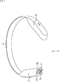
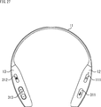
図1に示すように、情報処理端末1は、全体的に、正面視において略C型の外観形状を有するウェアラブル端末である。情報処理端末1は、薄い板状部材を湾曲させてなるバンド部11の左右の先端寄りの内側に、それぞれ、右側ユニット12と左側ユニット13が設けられることによって構成される。
As shown in FIG. 1, the
図1の左側に示す右側ユニット12は、バンド部11の厚みより正面視において太幅の筐体を有しており、バンド部11の内側の面から膨出するように形成される。
The
一方、右側に示す左側ユニット13は、バンド部11前方の開口を挟んで、右側ユニット12と略対称となる形状を有する。左側ユニット13は、右側ユニット12と同様に、バンド部11の厚みより正面視において太幅の筐体を有しており、バンド部11の内側の面から膨出するように形成される。
On the other hand, the
このような外観を有する情報処理端末1は、図2に示すように首に掛けて装着される。装着時、バンド部11の最奥部の内側がユーザの首の後ろに当たり、情報処理端末1は前傾した姿勢になる。ユーザから見て、右側ユニット12はユーザの首元の右側に位置し、左側ユニット13はユーザの首元の左側に位置することになる。
The
後に詳述するように、情報処理端末1は、撮影機能、音楽再生機能、無線通信機能、センシング機能などを有している。
As described later in detail, the
ユーザは、情報処理端末1を装着した状態で右側ユニット12に設けられたボタンを例えば右手で操作し、左側ユニット13に設けられたボタンを例えば左手で操作することで、それらの機能を実行させることができる。また、情報処理端末1には音声認識機能も搭載されている。ユーザは、発話によって情報処理端末1を操作することもできる。
The user operates the buttons provided on the
情報処理端末1の音楽再生機能によって右側ユニット12に設けられたスピーカから出力された音楽は主にユーザの右耳に届き、左側ユニット13に設けられたスピーカから出力された音楽は主にユーザの左耳に届く。
Due to the music playback function of the
ユーザは、情報処理端末1を装着し、音楽を聴きながら、ランニングをしたり自転車に乗ったりすることができる。音楽ではなく、ネットワークを介して取得されたニュースなどの各種の情報の音声が出力されるようにしてもよい。
The user can wear the
このように、情報処理端末1は、軽度な運動中に利用されることを想定した端末である。イヤホンなどを装着して耳を塞ぐわけではないから、ユーザは、スピーカから出力される音楽とともに周囲の音を聴くことができる。
As described above, the
図1の説明に戻り、右側ユニット12と左側ユニット13の先端には円弧面状となる曲面が形成される。右側ユニット12の先端には、上面前方寄りの位置から先端の曲面の上方寄りの位置にかけて略縦長長方形の開口部12Aが形成されている。開口部12Aは左上隅を凹ませた形状を有しており、その凹ませた位置にはLED(Light Emitting Diode)22が設けられる。
Returning to the description of FIG. 1, curved surfaces having an arc surface are formed at the tips of the
開口部12Aには、アクリルなどよりなる透明のカバー21が嵌め込まれる。カバー21の表面は、左側ユニット13の先端の曲面と略同一の曲率の曲面を形成する。カバー21の奥には、右側ユニット12の内部に設けられたカメラモジュールのレンズ31が配置される。カメラモジュールの撮影方向は、情報処理端末1を装着しているユーザから見て、ユーザの前方となる。
A
ユーザは、情報処理端末1を装着し、上述したように音楽を聴いてランニングをしたり自転車に乗ったりしながら、前方の風景を動画や静止画として撮影することができる。また、ユーザは、そのような撮影を、後に詳述するような音声コマンドによってハンズフリーで行うことができる。
The user can wear the
図3は、右側ユニット12の先端を拡大して示す図である。
FIG. 3 is an enlarged view showing the tip of the
情報処理端末1は、図3Aおよび図3Bに示すように、レンズ31の角度を上下方向に変え、撮影する画像の画角(撮影範囲)を制御することができる。図3Aは、レンズ31が下向きの状態を示し、図3Bは、レンズ31が上向きの状態を示す。
As shown in FIGS. 3A and 3B, the
すなわち、レンズ31が設けられたカメラモジュールは、電動による角度調整が可能な状態で右側ユニット12の内部に取り付けられている。
That is, the camera module provided with the
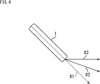
図4は、撮影角度を示す図である。 FIG. 4 is a diagram showing a shooting angle.
破線矢印#1は、情報処理端末1の側面(バンド部11の側面)の中心を通る矢印である。破線矢印#1、実線矢印#2,#3で示すように、上下方向の任意の角度にレンズ31の角度を調整することが可能とされる。図4において、情報処理端末1を斜めの状態で示していることは、情報処理端末1が装着状態であることを示す。
The dashed
このようなカメラモジュールの角度調整機能は、ユーザの行動状態に応じて最適な画角の画像を得るために用いられる。 Such an angle adjusting function of the camera module is used to obtain an image with an optimum angle of view according to the user's action state.
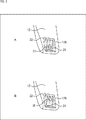
図5は、情報処理端末1を装着しているユーザの姿勢について説明する図である。
FIG. 5 is a diagram illustrating the posture of the user wearing the
図5Aは徒歩状態を示し、図5Bはユーザがスポーツタイプの自転車に乗っている状態を示す。情報処理端末1の角度は、情報処理端末1を装着しているユーザの行動状態に応じて変化する。
FIG. 5A shows a walking state, and FIG. 5B shows a state in which the user is riding a sports type bicycle. The angle of the
すなわち、徒歩状態のユーザの上半身は略直立の姿勢になっているのに対し、自転車に乗っている状態のユーザの上半身は前傾の姿勢になっており、後者の方が、情報処理端末1の姿勢もより前傾する。このことは、仮にカメラモジュールの角度を固定にした場合、画角の方向が、ユーザの行動状態に応じて変化することを表す。
That is, the upper half of the user in a walking state is in a substantially upright posture, whereas the upper half of the user in a bicycle is leaning forward, and the latter is in the
例えば、徒歩状態のときと自転車に乗っている状態のときとでは、カメラモジュールの角度はそれぞれ異なる角度に調整される。それぞれの行動状態に対して、最適な画角の画像を得るためのカメラモジュールの角度が設定されている。徒歩状態は、直立状態ということもできる。直立状態には、直立して歩行している状態だけでなく、直立して略停止している状態、直立して走行している状態も含まれる。また、自転車に乗っている状態には、自転車に乗って走行している状態だけでなく、自転車に乗って停止している状態も含まれる。 For example, the angle of the camera module is adjusted to different angles when walking and when riding a bicycle. The angle of the camera module for obtaining the image with the optimum angle of view is set for each action state. The walking state can be said to be upright. The upright state includes not only the state of standing upright and walking, but also the state of standing upright and substantially stopped, and the state of running upright. The state of riding a bicycle includes not only a state of riding on a bicycle but also a state of stopping on a bicycle.
情報処理端末1は、ユーザの行動状態を取得し(ユーザの行動状態を示す情報を取得し)、取得した行動状態に応じて、カメラモジュールの角度をユーザの操作によらずに自動的に調整してから撮影を行う。例えば、情報処理端末1は、ユーザが自転車に乗っていることを取得した場合、カメラモジュールの角度を図6の矢印#3で示す角度に調整する。
The
図6は、情報処理端末1を装着しているユーザがスポーツタイプの自転車に乗っているときの上半身を側面から示す概念図である。この場合、破線矢印#1で示す角度を0度とすると、50度だけ上に向けた矢印#3で示す角度が、自転車に乗っているときの、最適な画角の画像を得るためのカメラモジュールの角度になる。
FIG. 6 is a conceptual view showing the upper half of the body of the user wearing the
ユーザの行動状態は、例えば、情報処理端末1に内蔵されているセンサの出力に基づいて、情報処理端末1により取得される。情報処理端末1には、加速度センサ、ジャイロセンサ、電子コンパス、気圧センサ、測位センサ(GPS)などの各種のセンサが設けられている。
The user's action state is acquired by the
このように、情報処理端末1は、行動状態に応じてカメラモジュールの角度を調整することにより、一つの単位として得られる画像の撮影範囲を変化させ、行動状態に応じた最適な画角の画像を取得することができる。なお、ここでいう一つの単位には、静止画の一枚、動画の1フレームが含まれる。
In this way, the
また、情報処理端末1は、撮影を行わない場合、図7に示すように、カメラモジュールの角度を変え、レンズ31を隠すことができる。図7に示す状態は、レンズ31が開口部12Aから露出していない状態であり、外からは、カメラモジュールと一体的に回動するカメラカバーのみが確認できる。
Further, the
これにより、情報処理端末1を装着しているユーザの近くにいる人は、自分が撮影されているといった不安を感じないで済む。仮にレンズ31が露出したままの場合、撮影が行われていなかったとしても、情報処理端末1を装着しているユーザの近くにいる人はレンズ31の存在が気になってしまう。撮影を行っていないときにレンズ31を隠す構成は、他人に不安を与えるのを防ぎ、プライバシーに配慮した構成といえる。
As a result, a person near the user wearing the
カメラモジュールの角度、すなわちレンズ31の光軸の角度を変えることによって画像の画角を制御するものとしているが、レンズ31がズームレンズである場合、レンズ31の焦点距離を変えることによって、画角を制御するようにしてもよい。当然、光軸の角度と焦点距離の両方を変えることによって画角を制御することも可能である。光学的には、画像の撮影範囲は、レンズ31の光軸の角度と焦点距離によって規定される。
Although the angle of view of the image is controlled by changing the angle of the camera module, that is, the angle of the optical axis of the
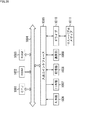
<<2.カメラブロックの構造>>
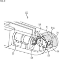
図8は、カメラブロックの構造を示す図である。上述したカメラモジュール、レンズ31などがカメラブロックに含まれる。
<<2. Structure of camera block >>
FIG. 8 is a diagram showing the structure of the camera block. The camera module, the
右側ユニット12のカバー21の内側には、薄板状の部材を湾曲させたカメラカバー51が設けられる。カメラカバー51は、開口部12Aから内部が見えないようにするためのものである。カメラカバー51には開口部51Aが形成されており、開口部51Aにはレンズ31が現れる。カメラカバー51は、カメラモジュール52の角度が調整されること合わせて回動する。
Inside the
カメラモジュール52は、略直方体状の本体を有し、上面にレンズ31を取り付けることによって構成される。カメラモジュール52は、回動軸が形成されたフレーム(図9等)に固定される。
The
カメラモジュール52の後方には、傘歯歯車53および傘歯歯車54が歯を嵌合させて設けられる。傘歯歯車53および傘歯歯車54は、後方にあるモータ55の動力を、カメラモジュール52が固定されたフレームに伝達する。
Bevel gears 53 and 54 are provided behind the
モータ55はステッピングモータであり、制御信号に応じて傘歯歯車54を回転させる。ステッピングモータを用いることにより、カメラブロックの小型化を実現することができる。モータ55が発生した動力は、傘歯歯車54、傘歯歯車53を介して、カメラモジュール52が固定されたフレームに伝達し、これにより、カメラモジュール52と、それと一体のレンズ31およびカメラカバー51が、フレームの軸を中心として回動する。
The
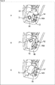
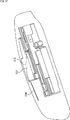
図9は、カメラブロックの構造を示す斜視図である。 FIG. 9 is a perspective view showing the structure of the camera block.
例えばユーザが徒歩状態のとき、カメラモジュール52の角度は図9Aに示す角度に調整される。図9Aに示す角度は、例えばカメラカバー51をクローズにした状態を基準とすると、最大の回動角度である。
For example, when the user is walking, the angle of the
カメラモジュール52の後方には、軸56Aを中心として回動するカメラフレーム56が設けられる。カメラモジュール52はカメラフレーム56に取り付けられる。
Behind the
図9Aの状態から角度を上向きにした場合、カメラモジュール52の向きは図9Bに示す状態になる。例えばユーザが自転車に乗っている状態のとき、カメラモジュール52の角度は図9Bに示す角度に調整される。図9Bに示す状態は、カメラモジュール52の角度が図6を参照して説明した50度の状態である。
When the angle is upward from the state of FIG. 9A, the orientation of the
図9Bの状態から角度をさらに上向きとし、カメラカバー51をクローズにした場合、カメラモジュール52の向きは図9Cに示す状態になる。図9Cの状態のとき、開口部12Aからは、カバー21を通してカメラカバー51のみが見え、レンズ31は見えない。例えば、カメラモジュール52の駆動は図9Cのクローズ状態から開始される。
When the angle is further raised from the state of FIG. 9B and the
カメラモジュール52の角度調整はこのようにして行われる。カメラモジュール52がいずれの角度にある場合であっても、カバー21の内側の面とレンズ31の距離は常に一定である。
The angle adjustment of the
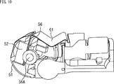
図10および図11は、カメラブロックの構造を他の方向から見た図である。 10 and 11 are views of the structure of the camera block viewed from another direction.
図10は、カメラモジュール52の状態が図9Aの状態にある場合の各構成を示す。
FIG. 10 shows each configuration when the
図10に示すように、カメラカバー51の形状は、側面視において略半円形状となる。カメラカバー51とカメラフレーム56の間を通して、フレキシブル配線61がカメラモジュール52に接続される。フレキシブル配線61は、可撓性を有する素材よりなり、カメラモジュール52と右側ユニット12内の基板との間の信号の送受信を行う。
As shown in FIG. 10, the
カメラモジュール52の回動に伴う劣化や断線を防ぐため、フレキシブル配線61の長さは、カメラモジュール52と基板間の距離にゆとりを持たせた長さとされる。図10の状態において、フレキシブル配線61は、カメラモジュール52の後方の位置で緩やかに谷折り状に折れ曲がる。
In order to prevent deterioration and disconnection due to the rotation of the
図11は、カメラモジュール52の状態が図9Bの状態にある場合の各構成を示す。
FIG. 11 shows each configuration when the
図11Aおよび図11Bに示すように、この場合、カメラフレーム56が略水平となり、フレキシブル配線61の撓みが大きくなる。図11Aに示すように、フレキシブル配線61の撓みを横から見た場合、その形状は略S字状になる。
In this case, as shown in FIGS. 11A and 11B, the
以上においては、カメラモジュール52の角度を上下方向にのみ調整することができるものとしたが、左右方向に調整することができるようにしてもよい。
Although the angle of the
<<3.撮影モード>>
ここで、情報処理端末1の撮影モードについて説明する。
<<3. Shooting mode >>
Here, the shooting mode of the
情報処理端末1には、例えば、静止画撮影モード、静止画連写モード、インターバル撮影モード、オート撮影モード、および動画撮影モードの各撮影モードが用意される。ユーザは、所定の撮影モードを選択し、撮影を行うことができる。
The
<3−1.静止画撮影モードの例>
図12は、静止画撮影モードの撮影シーケンスの例を示す図である。
<3-1. Example of still image shooting mode>
FIG. 12 is a diagram showing an example of a shooting sequence in the still image shooting mode.
静止画撮影モードは、静止画の撮影を1回行うモードである。図12の横軸は時刻を表す。図13以降においても同様である。 The still image shooting mode is a mode in which a still image is shot once. The horizontal axis of FIG. 12 represents time. The same applies to FIG. 13 and subsequent figures.
時刻t1において、情報処理端末1は、マイクロフォンにより集音されたユーザの音声に基づいて、静止画撮影モードのトリガとなる音声コマンドを検出する。図12の例においては、静止画撮影モードのトリガとなる音声は「hey take a picture」とされている。すなわち、ユーザは、ボタン操作によらずに、音声によって、静止画撮影モードを起動させることができる。
At time t1, the
静止画撮影モードのトリガとなる音声コマンドを検出した場合、時刻t2において、情報処理端末1は、効果音とともに「take a picture」などの音声をスピーカから出力させる。また、情報処理端末1は、LED22の発光を開始する。LED22の発光は時刻t5まで続けられる。LED22が発光することにより、撮影が行われていることをユーザや周りの人に知らせることができる。
When a voice command that triggers the still image shooting mode is detected, at time t2, the
時刻t3において、情報処理端末1は、カメラカバー51をオープンにする。情報処理端末1は、カメラモジュール52を回動させてカメラカバー51をオープンにすることにより、カメラモジュール52を初期状態する。カメラカバー51をオープンにすることにより、レンズ31が外から見える状態になる。
At time t3, the
時刻t4において、情報処理端末1は、カメラモジュール52の角度調整を行う。すなわち、情報処理端末1は、各種のセンサによる検出結果に基づいてユーザの行動状態を取得する。また、情報処理端末1は、取得した行動状態に応じてカメラモジュール52の角度を調整する。
At time t4, the
なお、レンズ31の光軸の方向が常に水平方向になるようにカメラモジュール52の角度が調整されるようにしてもよい。この場合、情報処理端末1は、加速度センサやジャイロセンサなどに基づいて情報処理端末1の姿勢を検出し、検出した姿勢に応じてカメラモジュール52の角度を調整することになる。
The angle of the
時刻t5において、情報処理端末1は、カメラモジュール52を制御し、撮影を行う。情報処理端末1は撮影に合わせて効果音をスピーカから出力する。カメラモジュール52の角度が行動状態に応じた角度に調整されているため、撮影によって取得された画像は、最適な画角の画像になる。情報処理端末1は、撮影によって得られた画像(静止画)を内部のメモリに保存する。
At time t5, the
時刻t6において、情報処理端末1は、カメラモジュール52の角度を戻し、時刻t7においてカメラカバー51をクローズにする。カメラカバー51をクローズにすることにより、レンズ31が外から見えない状態になる。
At time t6, the
静止画撮影モードによる撮影は、ユーザの発話をトリガとして以上のようにして行われる。ユーザは、例えば自転車に乗りながら声を発することで、走行中の前方の風景を撮影することができる。 The shooting in the still image shooting mode is performed as described above with the user's utterance as a trigger. The user can photograph the scenery in front of the user while riding, for example, by speaking while riding a bicycle.
<3−2.静止画連写モードの例>
図13は、静止画連写モードの撮影シーケンスの例を示す図である。
<3-2. Example of still image continuous shooting mode>
FIG. 13 is a diagram showing an example of a shooting sequence in the still image continuous shooting mode.
静止画連写モードは、静止画の撮影を続けて3回行うモードである。 The still image continuous shooting mode is a mode in which still images are continuously shot three times.
時刻t11において、情報処理端末1は、ユーザの音声に基づいて、静止画連写モードのトリガとなる音声コマンドを検出する。図13の例においては、静止画連写モードのトリガとなる音声は「hey take 3 picture」とされている。
At time t11, the
静止画連写モードのトリガとなる音声コマンドを検出した場合、時刻t12において、情報処理端末1は、効果音とともに「take 3 picture」などの音声をスピーカから出力させる。また、情報処理端末1は、LED22の発光を開始する。LED22の発光は、3回目の撮影が終わる時刻t18まで続けられる。
When a voice command that triggers the still image continuous shooting mode is detected, at time t12, the
時刻t13において、情報処理端末1は、カメラカバー51をオープンにする。
At time t13, the
時刻t14において、情報処理端末1は、ユーザの行動状態を取得し、カメラモジュール52の角度調整を行う。
At time t14, the
時刻t15において、情報処理端末1は、カメラモジュール52を制御し、1回目の撮影を行う。また、情報処理端末1は撮影に合わせて効果音をスピーカから出力する。情報処理端末1は、撮影によって得られた1枚目の画像を内部のメモリに保存する。
At time t15, the
時刻t16および時刻t17において、情報処理端末1は、それぞれ、2回目、3回目の撮影を行う。情報処理端末1は、撮影によって得られた2枚目の画像と3枚目の画像を内部のメモリに保存する。例えば、各撮影は一定の時間間隔で行われる。
At time t16 and time t17, the
時刻t19において、情報処理端末1は、カメラモジュール52の角度を戻し、時刻t20においてカメラカバー51をクローズにする。
At time t19, the
静止画連写モードによる3回の撮影は、ユーザの発話をトリガとして以上のようにして行われる。静止画連写モードによって撮影が4回以上行われるようにしてもよい。ユーザが発話によって指示した回数だけ、撮影が繰り返されるようにしてもよい。 The three shootings in the still image continuous shooting mode are performed as described above with the user's utterance as a trigger. The shooting may be performed four times or more in the still image continuous shooting mode. The photographing may be repeated as many times as the user instructs by the utterance.
<3−3.インターバル撮影モードの例>
図14は、インターバル撮影モードの撮影シーケンスの例を示す図である。
<3-3. Example of interval shooting mode>
FIG. 14 is a diagram showing an example of a shooting sequence in the interval shooting mode.
インターバル撮影モードは、設定された枚数の静止画を一定時間毎に繰り返し撮影するモードである。撮影間隔と撮影枚数が予め設定されている。 The interval shooting mode is a mode for repeatedly shooting a set number of still images at regular intervals. The shooting interval and the number of shots are preset.
時刻t31において、情報処理端末1は、ユーザの音声に基づいて、インターバル撮影モードのトリガとなる音声コマンドを検出する。図14の例においては、インターバル撮影モードのトリガとなる音声は「hey interval rec」とされている。
At time t31, the
インターバル撮影モードのトリガとなる音声コマンドを検出した場合、時刻t32において、情報処理端末1は、効果音とともに「start interval」などの音声をスピーカから出力させる。また、情報処理端末1は、LED22の発光を開始する。LED22の発光は、1回目の撮影が終わる時刻t36まで続けられる。
When a voice command that triggers the interval shooting mode is detected, at time t32, the
時刻t33において、情報処理端末1は、カメラカバー51をオープンにする。
At time t33, the
時刻t34において、情報処理端末1は、ユーザの行動状態を取得し、カメラモジュール52の角度調整を行う。
At time t34, the
時刻t35において、情報処理端末1は、カメラモジュール52を制御し、1回目の撮影を行う。また、情報処理端末1は撮影に合わせて効果音をスピーカから出力する。情報処理端末1は、撮影によって得られた1枚目の画像を内部のメモリに保存する。
At time t35, the
設定時間後の時刻t37において、情報処理端末1は、2回目の撮影を行う。情報処理端末1は、撮影によって得られた画像を内部のメモリに保存する。また、情報処理端末1は、撮影が終わる時刻t38までLED22を発光させる。このような撮影が、所定の時間間隔で繰り返される。
At time t37 after the set time, the
2回目以降の撮影時のカメラモジュール52の角度は、1回目の撮影時の角度と同じ角度であってもよいし、それぞれの撮影時におけるユーザの行動状態に応じて再度調整されるようにしてもよい。
The angle of the
時刻t39において、情報処理端末1は最後の撮影を行う。情報処理端末1は、撮影によって得られた画像を内部のメモリに保存する。また、情報処理端末1は、撮影が終わる時刻t40までLED22を発光させる。
At time t39, the
時刻t41において、情報処理端末1は、カメラモジュール52の角度を戻し、時刻t42においてカメラカバー51をクローズにする。
At time t41, the
インターバル撮影モードによる複数回の撮影は、ユーザの発話をトリガとして以上のようにして行われる。ユーザは、インターバル撮影モードを用いて、所定時間毎の風景を撮影することができる。 A plurality of times of shooting in the interval shooting mode is performed as described above, triggered by the user's utterance. The user can use the interval shooting mode to shoot a landscape every predetermined time.
<3−4.オート撮影モードの例>
図15は、オート撮影モードの撮影シーケンスの例を示す図である。
<3-4. Example of auto shooting mode>
FIG. 15 is a diagram showing an example of a shooting sequence in the auto shooting mode.
オート撮影モードは、所定の行動状態が取得されたときに撮影を開始するモードである。撮影間隔と撮影枚数が予め設定されている。また、オート撮影モードでの撮影のトリガとなる行動状態の種類も予め設定されている。情報処理端末1は、オート撮影モードが設定されている場合、ユーザの行動状態を取得する処理を繰り返し行う。
The auto shooting mode is a mode in which shooting is started when a predetermined action state is acquired. The shooting interval and the number of shots are preset. Further, the type of action state that triggers shooting in the auto shooting mode is also preset. When the automatic shooting mode is set, the
時刻t51において、情報処理端末1は、ユーザの行動状態として、サイクリング(自転車に乗っている)やランニングなどの予め設定された行動状態を取得する。これにより、オート撮影モードによる撮影が開始される。ユーザは、所定の行動をとるだけで撮影を開始させることができる。
At time t51, the
インターバル撮影モードのトリガとなる行動状態を取得した場合、時刻t52において、情報処理端末1は、効果音とともに「start auto photo」などの音声をスピーカから出力させる。また、情報処理端末1は、LED22の発光を開始する。LED22の発光は、1回目の撮影が終わる時刻t56まで続けられる。
When the action state that triggers the interval shooting mode is acquired, at time t52, the
時刻t53において、情報処理端末1は、カメラカバー51をオープンにする。
At time t53, the
時刻t54において、情報処理端末1は、時刻t51で特定したユーザの行動状態に応じてカメラモジュール52の角度調整を行う。
At time t54, the
時刻t55において、情報処理端末1は、カメラモジュール52を制御し、1回目の撮影を行う。また、情報処理端末1は撮影に合わせて効果音をスピーカから出力する。情報処理端末1は、撮影によって得られた1枚目の画像を内部のメモリに保存する。
At time t55, the
設定時間後の時刻t57において、情報処理端末1は、2回目の撮影を行う。情報処理端末1は、撮影によって得られた画像を内部のメモリに保存する。また、情報処理端末1は、撮影が終わる時刻t58までLED22を発光させる。このような撮影が、所定の時間間隔で繰り返される。
At time t57 after the set time, the
例えば、ユーザの行動状態として、時刻t51で取得された行動状態と異なる行動状態が取得された場合、オート撮影モードによる撮影は終了となる。 For example, when a behavior state different from the behavior state acquired at time t51 is acquired as the user's behavior state, the shooting in the automatic shooting mode ends.
時刻t51で特定された行動状態と異なる行動状態が取得された場合、時刻t59において、情報処理端末1は、カメラモジュール51の角度を戻し、時刻t60においてカメラカバー51をクローズにする。
When an action state different from the action state specified at time t51 is acquired, the
オート撮影モードによる撮影は、ユーザの行動状態をトリガとして以上のようにして行われる。ユーザは、自転車に乗るなどの予め設定しておいた行動をとることで、その行動をとっている間の風景を繰り返し撮影することができる。 The shooting in the auto shooting mode is performed as described above with the user's action state as a trigger. By taking a preset action such as riding a bicycle, the user can repeatedly capture the landscape while taking the action.
<3−5.動画撮影モードの例>
図16は、動画撮影モードの撮影シーケンスの例を示す図である。
<3-5. Example of movie shooting mode>
FIG. 16 is a diagram showing an example of a shooting sequence in the moving image shooting mode.
時刻t71において、情報処理端末1は、ユーザの音声に基づいて、動画撮影モードのトリガとなる音声コマンドを検出する。図16の例においては、動画撮影モードのトリガとなる音声は「hey start movie」とされている。
At time t71, the
動画撮影モードのトリガとなる音声コマンドを検出した場合、時刻t72において、情報処理端末1は、効果音とともに「start movie」などの音声をスピーカから出力させる。また、情報処理端末1は、LED22の発光を開始する。LED22の発光は、動画の撮影が終わる時刻t76まで続けられる。
When the voice command that triggers the moving image shooting mode is detected, at time t72, the
時刻t73において、情報処理端末1は、カメラカバー51をオープンにする。
At time t73, the
時刻t74において、情報処理端末1は、ユーザの行動状態を取得し、カメラモジュール52の角度調整を行う。動画の撮影も、カメラモジュール52の角度をユーザの行動状態に応じた角度に調整した状態で行われる。
At time t74, the
時刻t75において、情報処理端末1は、カメラモジュール52を制御し、動画の撮影を開始する。情報処理端末1は、撮影によって得られた動画を内部のメモリに順次保存する。
At time t75, the
時刻t76において、情報処理端末1は、マイクロフォンにより集音されたユーザの音声に基づいて、動画の撮影を終了させる「hey stop movie」などの音声コマンドを検出する。
At time t76, the
情報処理端末1に設けられた所定のボタンが操作された場合、動画の撮影が5分などの所定の時間続けられた場合、または、内部のメモリの容量に空きがなくなった場合も同様に動画の撮影は終了される。
The same applies when a predetermined button provided on the
時刻t77において、情報処理端末1は、カメラモジュール52の角度を戻し、時刻t78においてカメラカバー51をクローズにする。
At time t77, the
動画撮影モードによる動画の撮影は、ユーザの発話をトリガとして以上のようにして行われる。ユーザは、例えば自転車に乗りながら声を発することで、乗車中の前方の風景の動画を撮影することができる。 The shooting of a moving image in the moving image shooting mode is performed as described above with the user's utterance as a trigger. The user can shoot a moving image of the scenery in front of the user while riding, for example, by speaking while riding a bicycle.
<<4.情報処理端末の内部構成と動作>>
<4−1.情報処理端末の内部構成>
図17は、情報処理端末1の内部の構成例を示すブロック図である。
<<4. Internal configuration and operation of information processing terminal>>
<4-1. Internal configuration of information processing terminal>
FIG. 17 is a block diagram showing an internal configuration example of the
図17において、上述した構成と同じ構成には同じ符号を付してある。重複する説明については適宜省略する。 In FIG. 17, the same components as those described above are designated by the same reference numerals. A duplicate description will be omitted as appropriate.
アプリケーションプロセッサ101は、フラッシュメモリ102などに記憶されているプログラムを読み出して実行し、情報処理端末1の全体の動作を制御する。
The application processor 101 reads and executes a program stored in the flash memory 102 or the like, and controls the overall operation of the
アプリケーションプロセッサ101には、無線通信モジュール103、NFCタグ105、カメラモジュール52、モータ55、バイブレータ107、操作ボタン108、およびLED22が接続される。また、アプリケーションプロセッサ101には、電源回路109、USBインタフェース113、および信号処理回路114が接続される。
The wireless communication module 103, the
無線通信モジュール103は、外部の機器との間で、Bluetooth(登録商標)、Wi-Fiなどの所定の規格の無線通信を行うモジュールである。例えば、無線通信モジュール103は、ユーザが有するスマートホンなどの携帯端末と通信を行い、撮影によって得られた画像データを送信したり、音楽データを受信したりする。無線通信モジュール103にはBT/Wi-Fiアンテナ104が接続される。通信モジュール103は、WAN(Wide Area Network)を介した、例えば携帯電話通信(3G,4G,5Gなど)の通信をも行うことができるようにしてもよい。また、Bluetooth,Wi-Fi,WAN,NFCは、全てが実装される必要はなく、選択的に実装されてもよい。Bluetooth,Wi-Fi,WAN,NFCの通信を行うモジュールがそれぞれ別のモジュールとして設けられるようにしてもよいし、1つのモジュールとして設けられるようにしてもよい。
The wireless communication module 103 is a module that performs wireless communication with an external device according to a predetermined standard such as Bluetooth (registered trademark) or Wi-Fi. For example, the wireless communication module 103 communicates with a mobile terminal such as a smart phone of a user, transmits image data obtained by shooting, and receives music data. A BT/Wi-
NFC(Near Field Communication)タグ105は、NFCタグを有する機器が情報処理端末1に近付けられた場合、近接通信を行う。NFCタグ105にはNFCアンテナ106が接続される。
The NFC (Near Field Communication)
バイブレータ107は、アプリケーションプロセッサ101による制御に従って振動し、電話の着信、メールの受信などをユーザに通知する。ユーザが有する携帯端末からは、電話の着信を表す情報などが送信されてくる。
The
操作ボタン108は、情報処理端末1の筐体に設けられた各種のボタンである。操作ボタン108に対する操作の内容を表す信号はアプリケーションプロセッサ101に供給される。
The
電源回路109には、バッテリ110、電源ボタン111、LED112、およびUSBインタフェース113が接続される。電源回路109は、電源ボタン111が操作された場合、情報処理端末1を起動させ、バッテリ110からの電流を各部に供給する。また、電源回路109は、USBインタフェース113を介して供給された電流をバッテリ110に供給し、充電時させる。
A
USBインタフェース113は、USB端子に接続されたUSBケーブルを介して外部の機器と通信を行う。また、USBインタフェース113は、USBケーブルを介して供給された電流を電源回路109に供給する。
The
信号処理回路114は、各種のセンサからの信号、およびアプリケーションプロセッサ101から供給された信号の処理を行う。信号処理回路114に対しては、スピーカ116とマイクロフォン117が接続される。また、信号処理回路114に対しては、ジャイロセンサ118、電子コンパス119、および圧力センサ120がバス121を介して接続される。
The signal processing circuit 114 processes signals from various sensors and signals supplied from the application processor 101. A
例えば、信号処理回路114は、GPSアンテナ115から供給された信号に基づいて測位を行い、位置情報をアプリケーションプロセッサ101に出力する。すなわち、信号処理回路114はGPSセンサとして機能する。
For example, the signal processing circuit 114 performs positioning based on the signal supplied from the
また、信号処理回路114は、各センサによる検出結果を表すセンサデータを取得し、アプリケーションプロセッサ101に出力する。信号処理回路114からは、複数のセンサによる検出結果を表すセンサデータがバス121を介して供給される。信号処理回路114は、アプリケーションプロセッサ101から供給されたデータに基づいて、音楽、音声、効果音などをスピーカ116から出力させる。
Further, the signal processing circuit 114 acquires sensor data representing the detection result of each sensor and outputs the sensor data to the application processor 101. From the signal processing circuit 114, sensor data representing the detection results of the plurality of sensors is supplied via the
マイクロフォン117は、ユーザの音声を検出し、信号処理回路114に出力する。上述したように、情報処理端末1の操作は音声によっても行うことが可能とされる。
The
ジャイロセンサ118、電子コンパス119、および圧力センサ120は、それぞれ、角速度、方位、圧力を検出し、検出結果を表す信号を、バス121を介して信号処理回路114に出力する。
The
図17の例においては、外部の環境と情報処理端末1自身の状況を検出するセンサとして、カメラモジュール52、マイクロフォン117、ジャイロセンサ118、電子コンパス119、圧力センサ120、およびGPSセンサ(信号処理回路114)が設けられているが、他のセンサが設けられるようにしてもよい。例えば、加速度センサ、気圧センサ、近接センサ、生体センサ、皮膚電動マイクロフォン、地磁気センサ、慣性センサを設けることができる。慣性センサには、振動センサ、加速度センサ、ジャイロセンサが含まれる。
In the example of FIG. 17, the
図18は、情報処理端末1の機能構成例を示すブロック図である。
FIG. 18 is a block diagram showing a functional configuration example of the
図18に示す機能部のうちの少なくとも一部は、図17のアプリケーションプロセッサ101により所定のプログラムが実行されることによって実現される。 At least a part of the functional units shown in FIG. 18 is realized by executing a predetermined program by the application processor 101 of FIG.
情報処理端末1においては、行動状態取得部131、画角制御部132、および撮影制御部133が実現される。
In the
行動状態取得部131は、信号処理回路114から供給されたセンサデータに基づいて、ユーザの行動状態を取得する。例えば、行動状態取得部131は、それぞれの行動状態と、それぞれの行動をユーザがとっているときに検出されるセンサデータとを対応付けた認識用情報を有している。
The behavioral
行動状態取得部131は、行動状態の取得時、認識用情報を参照し、センサデータに対応付けられている行動状態をユーザの行動状態として取得する。行動状態取得部131は、取得した行動状態を表す情報を画角制御部132に出力する。
When acquiring the behavioral state, the behavioral
画角制御部132は、行動状態取得部131により取得された行動状態に応じてカメラモジュール52の角度を調整し、取得される画像の画角を制御する。画角制御部132は、行動状態とカメラモジュール52の角度とを対応付けた制御情報を有している。
The view
撮影制御部133は、カメラモジュール52の角度調整が行われた後、カメラモジュール52を制御し、上述した各種の撮影モードでの撮影を行う。撮影制御部133は、撮影によって得られた画像をフラッシュメモリ102に出力し、記憶させる。
After the angle of the
図19は、行動状態と画角とを対応付けた制御情報の例を示す図である。図19の内容を表す情報を、画角制御部132は制御情報として管理している。
FIG. 19 is a diagram showing an example of control information in which the action state and the angle of view are associated with each other. The view
図19の例においては、「歩き」、「走り」、「しゃがみこみ」、「椅子に座る」、「階段の昇降」、「坂道の上り下り」、「水泳」、「自転車」、「自動車」、「列車」のそれぞれの行動状態が示されている。このように、「自転車」以外の各種の乗り物に乗っている状態が行動状態として取得されるようにしてもよい。 In the example of FIG. 19, "walking", "running", "squatting", "sitting on a chair", "stair climbing", "climbing up and down", "swimming", "bicycle", "car", The respective behavior states of the "train" are shown. In this way, the state of riding on various types of vehicles other than “bicycle” may be acquired as the action state.
例えば、行動状態として「歩き」が取得された場合、画角制御部132は、重力加速度方向から上に80度の角度となるようにカメラモジュール52の角度を調整する。
For example, when “walking” is acquired as the action state, the view
図19の例においては、角度の基準が重力加速度方向とされているが、水平方向、図4の破線矢印#1で示した筐体方向、カメラモジュール52のクローズ時の角度などの、各種の基準を用いてそれぞれの角度を表すことが可能である。
In the example of FIG. 19, the gravitational acceleration direction is used as the angle reference, but various angles such as the horizontal direction, the housing direction indicated by the dashed
また、行動状態として「走り」が取得された場合、画角制御部132は、重力加速度方向から上に90度の角度となるようにカメラモジュール52の角度を調整する。
When “running” is acquired as the action state, the angle-of-
レンズ31がズームレンズである場合、角度を調整するだけでなく、レンズ31の焦点距離を長くして、画角を狭くするようにしてもよい。画角を狭めることを光学的に実現するのではなく、撮影された画像から一部の範囲をトリミングにより切り出すことによって電子的に実現するようにしてもよい。画角制御を電子的に行うことについては後述する。
When the
単に「歩き」と「走り」の行動状態によるだけでなく、カメラモジュール52の角度が速度に応じて調整されるようにしてもよい。
The angle of the
行動状態として「しゃがみこみ」が取得された場合、画角制御部132は、重力加速度方向から上に30度の角度となるようにカメラモジュール52の角度を調整する。
When “squatting down” is acquired as the action state, the angle-of-
この場合、適宜、画角を狭くするための光学的または電子的な制御が行われる。しゃがむ行動をとるユーザは、近くにあり、目の高さより下にある対象に注目しているものと考えられる。カメラモジュール52の角度を抑えることにより、ユーザが注目している対象を画角に収めた撮影が可能になる。
In this case, optical or electronic control is appropriately performed to narrow the angle of view. It is considered that the user who takes a crouching action is paying attention to an object that is near and below eye level. By suppressing the angle of the
行動状態として「椅子に座る」が取得された場合、画角制御部132は、重力加速度方向から上に45度の角度となるようにカメラモジュール52の角度を調整する。また、適宜、画角を狭くするための光学的または電子的な制御が行われる。
When “sit on a chair” is acquired as the action state, the angle-of-
行動状態として「階段の昇降」が取得された場合、画角制御部132は、レンズカバー51をクローズとしてレンズ31を収納し、撮影不可の状態にする。例えば階段を上っているときに撮影不可にすることにより、盗撮目的での情報処理端末1の利用を防ぐことが可能になる。
When “up and down stairs” is acquired as the action state, the angle-of-
行動状態として階段を昇っていることが取得された場合、画角制御部132は、重力加速度方向から上に120度の角度となるようにカメラモジュール52の角度を調整する。撮影不可とするか、上に120度の角度となるように角度調整を行うかは、適宜選択されるようにしてもよい。また、行動状態として階段を降りていることが取得された場合、画角制御部132は、重力加速度方向から上に60度の角度となるようにカメラモジュール52の角度を調整する。
When it is acquired that the user is climbing the stairs as the action state, the angle-of-
坂道を登っていることが取得された場合、階段を昇っているときと同様の制御が行われる。また、坂道を下っていることが取得された場合、階段を降りているときと同様の制御が行われる。 If it is acquired that the user is climbing a slope, the same control as when climbing stairs is performed. Further, when it is acquired that the vehicle is going down a slope, the same control as when going down the stairs is performed.
行動状態として遅い速度で泳いでいる状態が取得された場合、画角制御部132は、重力加速度方向から上に30度の角度となるようにカメラモジュール52の角度を調整する。情報処理端末1は防水性能を有している。
When the state of swimming at a slow speed is acquired as the action state, the view
また、行動状態として速い速度で泳いでいる状態が取得された場合、画角制御部132は、重力加速度方向から上に90度の角度となるようにカメラモジュール52の角度を調整する。
Further, when the state of swimming at a high speed is acquired as the action state, the angle-of-
行動状態として遅い速度で自転車を走行している状態が取得された場合、画角制御部132は、重力加速度方向から上に50度の角度となるようにカメラモジュール52の角度を調整する。
When the state in which the bicycle is traveling at a slow speed is acquired as the action state, the angle-of-
また、行動状態として速い速度で自転車を走行している状態が取得された場合、画角制御部132は、重力加速度方向から上に55度の角度となるようにカメラモジュール52の角度を調整する。
Further, when the state of traveling the bicycle at a high speed is acquired as the action state, the angle-of-
行動状態として自動車を運転している状態が取得された場合、画角制御部132は、重力加速度方向から上に85度の角度となるようにカメラモジュール52の角度を調整する。また、適宜、歩いているときと比べて、画角を広くするための光学的または電子的な制御が行われる。
When the state of driving the automobile is acquired as the action state, the angle-of-
ユーザの頭の方向に連動させて、画角を左右に変えるようにしてもよい。画角を左右に変えることは、カメラモジュール52の角度を上下だけでなく左右にも変えることができるようになっている場合には光学的に行われる。左右に変えることができるようになっていない場合、画角を左右に変えることは電子的に行われる。
The angle of view may be changed right and left in association with the direction of the user's head. Changing the angle of view to the left or right is performed optically when the angle of the
行動状態として列車に乗っている状態が取得された場合、画角制御部132は、重力加速度方向から上に85度の角度、かつ、進行方向等の所定の方向を基準として右または左方向に50度となるようにカメラモジュール52の角度を調整する。行動状態として運転していないが自動車に乗っている状態が取得された場合も同様の制御が行われる。
When the state of getting on the train is acquired as the action state, the angle-of-
画角制御部132は、このような制御情報に基づいて、カメラモジュール52の角度の調整等を行う。なお、図19に示す角度は任意に変更可能である。「水泳」が取得された場合にレンズ31を収納して撮影不可にするといったように、行動状態と制御内容との対応関係は任意に変更可能である。また、行動状態だけでなく、情報処理端末1の姿勢、装着位置、移動する速さなどの他の環境情報にも基づいて角度調整が行われるようにしてもよい。移動する速さは数値によって表される移動速度であってもよい。角度調整に用いる情報の組み合わせは任意である。
The angle-of-
<4−2.情報処理端末の動作>
次に、図20のフローチャートを参照して、情報処理端末1の撮影処理について説明する。図20の処理は、例えば、ユーザの発話に基づいて音声コマンドが検出されたときに開始される。
<4-2. Operation of information processing terminal>
Next, the photographing process of the
ステップS1において、行動状態取得部131は、信号処理回路114から供給されたセンサデータに基づいてユーザの行動状態を取得する。ここでは、図19を参照して説明したような各種の行動状態が取得される。
In step S1, the behavioral
ステップS2において、画角制御部132は、行動状態取得部131により取得された行動状態に応じてカメラモジュール52の角度を調整し、取得される画像の画角を制御する。
In step S2, the view
ステップS3において、撮影制御部133は、カメラモジュール52の角度調整が行われた後、カメラモジュール52を制御し、撮影モードに応じた撮影を行う。撮影制御部133は、撮影により得られた画像をフラッシュメモリ102に保存し、処理を終了させる。
In step S3, the
以上のように、複数種類の行動状態のそれぞれに対してカメラモジュール52の制御内容が決められているため、情報処理端末1は、それぞれの行動状態に応じた、最適な画角の画像を得ることができる。
As described above, since the control content of the
例えば静止画撮影モードでの撮影においては、撮影を行う毎にユーザの行動状態を取得し、カメラモジュール52の角度を調整するようになされている。従って、情報処理端末1は、筐体の姿勢やユーザの行動状態が変化した場合であっても、それに追従して、常に最適な画角の画像を撮影することが可能になる。インターバル撮影や動画撮影モードでの一回の撮影中にユーザの行動状態が周期的に取得され、カメラモジュール52の角度がその都度調整されるようにしてもよい。
For example, in photographing in the still image photographing mode, the behavior state of the user is acquired and the angle of the
さらに、ユーザは、情報処理端末1に触れずに、音声で情報処理端末1を操作することができる。すなわち、撮影時にボタンを操作する必要がある場合、操作の内容によってはその行動を中断しなければならないこともあるが、そのような必要がなく、思い立ったときに、快適に、かつ自然な撮影が可能になる。ボタンの数を抑えることができることにより、情報処理端末1の筐体の強度の確保や防水性を確保する上でも有利となる。
Furthermore, the user can operate the
<<5.変形例>>
<5−1.制御システムの例>
行動状態の取得、調整角度の決定、および角度調整の全ての処理が情報処理端末1により行われるものとしたが、行動状態の取得と調整角度の決定については、他の機器により行われるようにすることが可能である。
<<5. Modification>>
<5-1. Example of control system>
It is assumed that the
図21は、制御システムの例を示す図である。 FIG. 21 is a diagram showing an example of a control system.
図21の制御システムは、情報処理端末1と携帯端末201から構成される。携帯端末201は、情報処理端末1を装着しているユーザが携帯しているスマートホンなどの端末である。情報処理端末1と携帯端末201は、BluetoothやWi-Fiなどの無線通信を介して接続される。
The control system of FIG. 21 includes the
情報処理端末1は、撮影時、各センサの検出結果を表すセンサデータを携帯端末201に送信する。情報処理端末1から送信されてきたセンサデータを受信した携帯端末201は、ユーザの行動状態をセンサデータに基づいて特定し、行動状態を表す情報を情報処理端末1に送信する。
The
情報処理端末1は、携帯端末201から送信されてきた情報を受信し、携帯端末201により特定されたユーザの行動状態を取得する。情報処理端末1は、取得した行動状態に応じた調整角度を決定し、カメラモジュール52の角度を調整して撮影を行う。
The
この場合、図18の行動状態取得部131と同様の機能を有する構成が携帯端末201において実現される。また、図18の画角制御部132と撮影制御部133は情報処理端末1において実現される。
In this case, the
このように、少なくとも一部の処理を情報処理端末1とは異なる他の機器に行わせることも可能である。行動状態の取得だけでなく、行動状態に応じたカメラモジュール52の調整角度を決定する処理までが、携帯端末201により行われるようにしてもよい。
In this way, at least a part of the processing can be performed by another device different from the
図22は、制御システムの他の例を示す図である。 FIG. 22 is a diagram showing another example of the control system.
図22の制御システムは、情報処理端末1、携帯端末201、および制御サーバ202から構成される。携帯端末201と制御サーバ202は、インターネットなどのネットワーク203を介して接続される。
The control system of FIG. 22 includes an
携帯端末201がいわゆるテザリング機能を有している場合、情報処理端末1が携帯端末201を経由してネットワーク203に接続されるようにしてもよい。この場合、情報処理端末1と制御サーバ202の間の情報の送受信は、携帯端末201とネットワーク203を介して行われる。
When the
図21を参照して説明した場合と同様に、情報処理端末1は、撮影時、各センサの検出結果を表すセンサデータを制御サーバ202に送信する。情報処理端末1から送信されてきたセンサデータを受信した制御サーバ202は、ユーザの行動状態をセンサデータに基づいて特定し、行動状態を表す情報を情報処理端末1に送信する。
As in the case described with reference to FIG. 21, the
情報処理端末1は、制御サーバ202から送信されてきた情報を受信し、制御サーバ202により特定されたユーザの行動状態を取得する。情報処理端末1は、取得した行動状態に応じた調整角度を決定し、カメラモジュール52の角度を調整して撮影を行う。
The
この場合、図18の行動状態取得部131と同様の機能を有する構成が制御サーバ202において実現される。図18の画角制御部132と撮影制御部133は情報処理端末1において実現される。
In this case, the
このように、少なくとも一部の処理を、ネットワーク203を介して接続される機器に行わせることも可能である。行動状態の取得だけでなく、行動状態に応じたカメラモジュール52の調整角度を決定する処理までが、制御サーバ202により行われるようにしてもよい。
In this way, at least a part of the processing can be performed by a device connected via the
<5−2.画角制御を電子的に行う例>
画角の制御を光学的に行う場合について主に説明したが、トリミングにより切り出す範囲を変えることで電子的に行うことも可能である。この場合、レンズ31には、魚眼レンズなどの焦点距離の短いレンズが用いられる。
<5-2. Example of electronically controlling the angle of view>
Although the case where the angle of view is optically controlled has been mainly described, it is also possible to electronically control the range to be cut out by trimming. In this case, a lens having a short focal length such as a fisheye lens is used as the
図23は、電子的な画角制御の例を示す図である。 FIG. 23 is a diagram showing an example of electronic view angle control.
図23の半円球はレンズ31により取り込まれる全範囲を示す。位置Pはレンズ31の位置を示す。なお、図23は、切り出し範囲を変えることの概念を説明するものであり、枠の大きさ、曲率等は正確なものではない。
The hemisphere in FIG. 23 shows the entire range captured by the
例えば、ユーザが歩いている場合、カメラモジュール52により撮影された半円球で示す画像全体のうち、枠F1で示す範囲の画像がトリミングにより切り出される。枠F1で示す範囲の画像が、行動状態に応じた画角の画像として取得される。
For example, when the user is walking, the image in the range indicated by the frame F1 is cut out by trimming from the entire image shown by the hemisphere captured by the
また、ユーザが走っている場合、カメラモジュール52により撮影された半円球で示す画像全体のうち、枠F2で示す範囲の画像がトリミングにより切り出される。枠F2で示す範囲の画像が、行動状態に応じた画角の画像として取得される。
When the user is running, the image in the range indicated by the frame F2 is cut out by trimming from the entire image shown by the hemisphere captured by the
枠F2の範囲は枠F1の範囲より上に設定されている。これにより、ユーザが走っているとき、歩いているときより上方の範囲の画像が取得されることになる。図19等を参照して説明したように、歩いているときと走っているときを比べた場合、後者の方が、より上方の画角の画像が取得される。 The range of the frame F2 is set above the range of the frame F1. As a result, when the user is running, an image in the upper range than when the user is walking is acquired. As described with reference to FIG. 19 and the like, when comparing walking and running, the latter obtains an image with a higher angle of view.
また、枠F2の範囲は枠F1の範囲より狭い範囲である。トリミングにより切り出す範囲を狭くすることによって、ズームレンズの焦点距離を変えるときと同様に画角を制御することができる。 The range of the frame F2 is narrower than the range of the frame F1. By narrowing the range to be cut out by trimming, the angle of view can be controlled in the same manner as when changing the focal length of the zoom lens.
このように、画角の制御を電子的に行うことにより、カメラモジュール52の角度を調整するための機構を設ける必要がなく、情報処理端末1の小型化を実現することができる。光学的な画角制御と電子的な画角制御とを組み合わせて用いることも可能である。
As described above, by electronically controlling the angle of view, it is not necessary to provide a mechanism for adjusting the angle of the
<5−3.行動状態の特定の例>
センサデータに基づいて行動状態を取得するものとしたが、行動状態の取得方法は任意に変更可能である。
<5-3. Specific example of behavioral state>
Although the behavioral state is acquired based on the sensor data, the method of acquiring the behavioral state can be arbitrarily changed.
・位置情報を用いた例
GPSセンサとしての信号処理回路114により検出された位置情報に基づいてユーザの行動状態が取得されるようにしてもよい。この場合、行動状態取得部131は、位置情報と行動状態とを対応付けた情報を管理している。
・Example of using location information
The action state of the user may be acquired based on the position information detected by the signal processing circuit 114 as the GPS sensor. In this case, the action
行動状態取得部131が管理する情報においては、例えば、公園の位置情報と行動状態としてのランニング(「走り」)が対応付けられる。また、自宅の位置情報と座っていることが対応付けられ、自宅と最寄り駅の間の道路上の位置情報と歩いていることが対応付けられる。
In the information managed by the action
行動状態取得部131は、撮影時に測定された現在位置と対応付けて管理している行動状態を、ユーザの現在の行動状態として取得する。これにより、情報処理端末1は、現在位置を測定することでユーザの行動状態を取得することができる。
The behavioral
・接続先の情報を用いた例
無線通信の接続先の機器に基づいてユーザの行動状態が特定されるようにしてもよい。この場合、行動状態取得部131は、接続先の機器の識別情報と行動状態とを対応付けた情報を管理している。
-Example using information of connection destination The behavior state of the user may be specified based on the device of the connection destination of the wireless communication. In this case, the behavioral
行動状態取得部131が管理する情報においては、例えば、公園に設置されたアクセスポイントの識別情報と行動状態としてのランニングが対応付けられる。また、自宅に設置されたアクセスポイントの識別情報と座っていることが対応付けられ、自宅と最寄り駅の間に設置されたに設置されたアクセスポイントの識別情報と歩いていることが対応付けられる。
In the information managed by the action
無線通信モジュール103は、Wi-Fiなどの無線通信の接続先となる機器を周期的に探索する。行動状態取得部131は、撮影時に接続先になっている機器と対応付けて管理している行動状態を、ユーザの現在の行動状態として取得する。これにより、情報処理端末1は、接続先となる機器を探索することでユーザの行動状態を取得することができる。
The wireless communication module 103 periodically searches for a device as a connection destination of wireless communication such as Wi-Fi. The behavioral
・近接された機器の情報を用いた例
上述したように、情報処理端末1は、NFCタグ105を内蔵しており、近接された機器と近距離の無線通信を行うことが可能である。撮影を行う前に近接された機器に基づいてユーザの行動状態が取得されるようにしてもよい。この場合、行動状態取得部131は、近接された機器の識別情報と行動状態とを対応付けた情報を管理している。
-Example Using Information of Closed Device As described above, the
行動状態取得部131が管理する情報においては、例えば、自転車に内蔵されたNFCタグの識別情報と行動状態としての自転車に乗っていることが対応付けられる。また、自宅の椅子に内蔵されたNFCタグの識別情報と座っていることが対応付けられ、ランニングシューズに内蔵されたNFCタグの識別情報とランニングが対応付けられる。
In the information managed by the behavior
ユーザは、例えば、情報処理端末1を装着して自転車に乗る前、自転車に内蔵されたNFCタグに情報処理端末1を近接させる。行動状態取得部131は、自転車のNFCタグに近接されたことを検出した場合、それ以降、自転車に乗っているものとしてユーザの行動状態を取得する。
For example, the user puts the
このように、行動状態を取得するための方法として各種の方法を用いることが可能である。 As described above, various methods can be used as a method for acquiring the behavioral state.
<5−4.端末形状の例>
・装着位置の例
情報処理端末1が首掛け型のウェアラブル端末であるものとしたが、カメラを有する他の形状のウェアラブル端末にも、上述した画角の制御機能を適用可能である。
<5-4. Example of terminal shape>
-Example of Wearing Position Although the
図24は、他の形状の情報処理端末の例を示す図である。 FIG. 24 is a diagram illustrating an example of an information processing terminal having another shape.
図24の携帯端末211は、筐体の背面に設けられたクリップなどを用いてユーザの体の任意の位置に装着可能なウェアラブル端末である。図24の例においては、ユーザの胸付近の位置に携帯端末211が取り付けられている。携帯端末211の筐体の正面にはカメラ221Aが設けられる。
The
携帯端末211が手首、足首などの他の位置に装着されるようにしてもよい。頭部より下であり、端末の姿勢が主にユーザの上半身の姿勢によって決まる肩や腰の周りなどの部位に取り付けられる端末にも、上述した画角の制御機能を適用可能である。この場合、取り付けられた位置によって、画角の制御内容が変わるようにしてもよい。
The
また、情報処理端末1や携帯端末211を、自動車のダッシュボードに取り付けられたマウントや、自転車のハンドルに取り付けられたマウントに装着して利用することができるようにしてもよい。この場合、情報処理端末1や携帯端末211は、いわゆるドライブレコーダや障害物センサとして用いられる。
Further, the
・雲台に適用した例
カメラの画角を制御する雲台に上述した画角の制御機能を適用するようにしてもよい。
-Example of application to pan head The above-mentioned view angle control function may be applied to a pan head that controls the view angle of a camera.
図25は、情報処理端末としての雲台の例を示す図である。 FIG. 25 is a diagram showing an example of a pan head as an information processing terminal.
雲台231は、クリップなどによりユーザの体に装着可能な雲台である。ユーザは、カメラ241を載置した雲台231を、胸、肩、手首、足首などの所定の位置に装着する。雲台231とカメラ241は無線または有線により通信を行うことができる。
The
雲台231は、行動状態の取得に用いられるセンサデータを検出するセンサの他に、アプリケーションプロセッサを内蔵している。雲台231のアプリケーションプロセッサは、所定のプログラムを実行し、図18を参照して説明した機能を実現する。
The
すなわち、雲台231は、撮影時、ユーザの行動状態をセンサデータに基づいて取得し、取得した行動状態に応じて、カメラ241の角度を調整する。雲台231は、角度の調整後に撮影を行わせることによって、カメラ241により撮影される画像の画角を制御する。
That is, the
このように、撮影機能を有していない雲台などの機器にも上述した画角の制御機能を適用可能である。 In this way, the control function of the angle of view described above can be applied to a device such as a platform that does not have a photographing function.
<5−5.その他の例>
各行動状態に応じた角度調整に用いるパラメータ(角度)は、設計時のまま固定の値であってもよいし、装着位置の違い、体格差、自転車乗車時の姿勢の違いなどに応じて、適宜変更されるようにしてもよい。
<5-5. Other examples>
The parameter (angle) used for angle adjustment according to each action state may be a fixed value as it is at the time of design, or depending on the mounting position, the difference in physique, the difference in posture when riding a bicycle, etc. You may make it change suitably.
パラメータの変更は、例えば、歩行時などの定常状態を基準として自動的に行われるようにしてもよいし、ユーザが手動で行うようにしてもよい。 The parameters may be changed automatically on the basis of a steady state such as walking, or may be manually changed by the user.
また、カメラブロックが右側ユニット12に設けられるものとしたが、左側ユニット13に設けられるようにしてもよいし、両方に設けられるようにしてもよい。また、レンズ31が正面を向いているのではなく、横方向に向いた状態で設けられるようにしてもよい。
Further, although the camera block is provided in the
撮影を行わない場合にカメラカバー51がクローズになるものとしたが、撮影によって得られた画像を用いて人物の認識を行い、所定の大きさ以上の大きさで人が写っている場合にカメラカバー51をクローズにするようにしてもよい。これにより、情報処理端末1を装着しているユーザに人が近づいている場合に、その人を撮影してしまうのを防ぐことができる。
Although the
撮影によって得られる画像の画角を、ユーザが音声によって調整することができるようにしてもよい。 The user may be allowed to adjust the angle of view of the image obtained by shooting by voice.
また、カメラ52の角度の調整方向を、ロール方向、ピッチ方向、ヨー方向としてもよい。
Further, the adjustment direction of the angle of the
上述したように、開口部12Aに嵌め込まれるカバー21は曲面を形成する。このため、カメラ52により撮影された画像の縁近傍の写りは、中心付近の写りと比べて、解像度が落ちたり、被写体に歪みが生じたりしたものとなる可能性がある。
As described above, the
撮影された画像に対して画像処理を施すことにより、このような部分的な写りの劣化を防ぐようにしてもよい。カバー21やレンズ31の特性を位置に応じて変えることにより、部分的な写りの劣化を光学的に防ぐようにしてもよい。さらに、カメラモジュール52内の撮像素子の画素ピッチを撮像素子の中央付近と縁近傍とで変えるといったように、撮像素子自体の特性を変えるようにしてもよい。
Image degradation may be performed on the captured image to prevent such partial deterioration of the image. The characteristics of the
右側ユニット12と左側ユニット13をバンド部11に対して着脱可能としてもよい。ユーザは、自分の首周りの長さに合わせた長さのバンド部11を選択し、右側ユニット12と左側ユニット13をバンド部11に取り付けることで、情報処理端末1を構成することができる。
The
<<6.情報処理端末の構造の詳細>>
次に、情報処理端末1の構造の詳細について説明する。
<<6. Details of the structure of the information processing terminal >>
Next, details of the structure of the
図26および図27は、情報処理端末1の外観を示す図である。
26 and 27 are diagrams showing the outer appearance of the
図26の中央に正面視の情報処理端末1の外観を示す。図26に示すように、情報処理端末1の左側面にはスピーカ穴301が形成され、右側面にはスピーカ穴302が形成される。
The center of FIG. 26 shows the appearance of the
図27に示すように、右側ユニット12の背面には電源ボタン111とUSB端子311が設けられる。USB端子311には例えば樹脂製のカバーが被せられる。
As shown in FIG. 27, a
左側ユニット13の背面には、各種の設定を行うときに操作されるカスタムボタン312と、音量を調整するときに操作される音量ボタン313が設けられる。
On the back surface of the
また、左側ユニット13の内側の先端近傍には、図28に示すようにアシストボタン314が設けられる。アシストボタン314には、動画の撮影終了などの所定の機能が割り当てられる。カスタムボタン312、音量ボタン313、およびアシストボタン314が、図17の操作ボタン108に相当する。
Further, an
図29は、右側ユニット12の内部の構成例を示す図である。
FIG. 29 is a diagram showing an internal configuration example of the
右側ユニット12は、ベース部材331、GPSアンテナ115、スピーカボックス332、BT/Wi-Fiアンテナ104、カメラブロック333、基板ブロック334、および配線335を重ね、外装ケース341を被せることによって構成される。
The
基板ブロック334に接して配置されるスピーカボックス332は、基板ブロック334の熱を放熱するためにアルミにより成型される。BT/Wi-Fiアンテナ104とGPSアンテナ115は、スピーカボックス332と位置をずらして配置される。
The
図30は、左側ユニット13の内部の構成例を示す図である。
FIG. 30 is a diagram showing an internal configuration example of the
左側ユニット13は、ベース部材361、スピーカボックス362、NFCアンテナ106、バッテリ110、および配線363を重ね、外装ケース371を被せることによって構成される。
The
右側ユニット12内の構成と左側ユニット13内の構成を繋ぐバンド内フレキシブル配線351は、バンド部11の内部に形成された空洞を通して配置される。バンド部11はチューブ構造を有している。フレキシブル配線の代わりに、ケーブルハーネスを用いて右側ユニット12内の構成と左側ユニット13内の構成が接続されるようにしてもよい。
The in-band
図31は、各構成の配置の例を示す図である。説明の便宜上、図31においては、構成の詳細な図示を省略している。 FIG. 31 is a diagram showing an example of arrangement of each configuration. For convenience of description, detailed illustration of the configuration is omitted in FIG.
図31に示すように、右側ユニット12において、BT/Wi-Fiアンテナ104とGPSアンテナ115は、スピーカボックス332より情報処理端末1の側面に近い位置に設けられる。また、基板ブロック334等とバンド内フレキシブル配線351を繋ぐ配線335は、基板ブロック334を避け、右側ユニット12の外形に沿って配置される。図31において、配線335は太線で示されている。
As shown in FIG. 31, in the
一方、左側ユニット13において、バッテリ110等とバンド内フレキシブル配線351を繋ぐ配線363は、バッテリ110を避け、左側ユニット13の外形に沿って配置される。図31において、配線363は太線で示されている。
On the other hand, in the
なお、マイクロフォン117は例えば4個設けられる。4個のマイクロフォン117は、それぞれ、例えば、円で囲んで示す位置P11乃至P14近傍に設けられる。
Note that four
上述したように、近接センサ、生体センサ、皮膚電動マイクロフォンを情報処理端末1に搭載することができる。この場合、人体に近付けられていることを検出する近接センサは、例えば図31の位置P21として示すバンド部11の位置に設けることができる。
As described above, the proximity sensor, the biometric sensor, and the skin electric microphone can be mounted on the
また、近接センサ、生体センサ、皮膚電動マイクロフォンは、装着したときに首の前方の近くに位置する、位置P22,P23として示す位置に設けることができる。位置P22,P23は、右側ユニット12と左側ユニット13の膨出部近傍の位置であり、装着時に肌に近くなるためにセンサの感度を向上させることができる。
Further, the proximity sensor, the biometric sensor, and the skin electric microphone can be provided at the positions shown as positions P22 and P23, which are located near the front of the neck when worn. Positions P22 and P23 are positions in the vicinity of the bulging portions of the
図32は、右側ユニット12に収納される基板ブロック334を示す図である。
FIG. 32 is a diagram showing the
基板ブロック334は、基板401、基板402、基板403の3層構造を有している。各基板は図33に示すように電気的に接続される。
The
基板401は、信号処理回路114のICチップが設けられる基板であり、基板402の長さに対して略2/3の長さを有する。基板402は、アプリケーションプロセッサ101が設けられる基板である。下層の基板403は、無線通信モジュール103が設けられる基板であり、基板402の長さに対して略1/3の長さを有する。
The
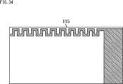
図34は、GPSアンテナ115の配線例を示す図である。
FIG. 34 is a diagram showing a wiring example of the
図34に示すように、GPSアンテナ115は、ミアンダ配線部分と容量装荷部分を有するFPC(Flexible Printed Circuits)により構成される。このような構成を有するGPSアンテナ115は、図35に示すように、スピーカボックス332より情報処理端末1の側面に近い位置に配置される。GPSアンテナ115と基板ブロック334の基板402は配線411により接続され、基板402のGNDがアンテナ地板として用いられる。
As shown in FIG. 34, the
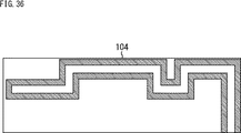
図36は、BT/Wi-Fiアンテナ104の配線例を示す図である。
FIG. 36 is a diagram showing a wiring example of the BT/Wi-
図36に示すように、BT/Wi-Fiアンテナ104は、Uターン型の配線を有するFPCにより構成される。このような構成を有するBT/Wi-Fiアンテナ104は、図37に示すように、スピーカボックス332と位置をずらして、情報処理端末1の側面に近い位置に配置される。BT/Wi-Fiアンテナ104を構成するFPCのGND部分がスピーカボックス332上に貼り付けられ、アンテナ地板として用いられる。BT/Wi-Fiアンテナ104と基板ブロック334の基板402は同軸線412により接続され、同軸線412により給電が行われるようになされている。
As shown in FIG. 36, the BT/Wi-
<<7.その他>>
<7−1.コンピュータの構成例>
上述した一連の処理は、ハードウェアにより実行することもできるし、ソフトウェアにより実行することもできる。一連の処理をソフトウェアにより実行する場合には、そのソフトウェアを構成するプログラムが、専用のハードウェアに組み込まれているコンピュータ、または汎用のパーソナルコンピュータなどに、プログラム記録媒体からインストールされる。
<<7. Other >>
<7-1. Example of computer configuration>
The series of processes described above can be executed by hardware or software. When the series of processes is executed by software, the program forming the software is installed from a program recording medium to a computer incorporated in dedicated hardware or a general-purpose personal computer.
図38は、上述した一連の処理をプログラムにより実行するコンピュータのハードウェアの構成例を示すブロック図である。 FIG. 38 is a block diagram showing a configuration example of hardware of a computer that executes the series of processes described above by a program.
CPU1001、ROM1002、RAM1003は、バス1004により相互に接続されている。
The
バス1004には、さらに、入出力インタフェース1005が接続されている。入出力インタフェース1005には、キーボード、マウスなどよりなる入力部1006、ディスプレイ、スピーカなどよりなる出力部1007が接続される。また、入出力インタフェース1005には、ハードディスクや不揮発性のメモリなどよりなる記憶部1008、ネットワークインタフェースなどよりなる通信部1009、リムーバブルメディア1011を駆動するドライブ1010が接続される。
An input/
以上のように構成されるコンピュータでは、CPU1001が、例えば、記憶部1008に記憶されているプログラムを入出力インタフェース1005及びバス1004を介してRAM1003にロードして実行することにより、上述した一連の処理が行われる。
In the computer configured as described above, the
CPU1001が実行するプログラムは、例えばリムーバブルメディア1011に記録して、あるいは、ローカルエリアネットワーク、インターネット、デジタル放送といった、有線または無線の伝送媒体を介して提供され、記憶部1008にインストールされる。
The program executed by the
なお、コンピュータが実行するプログラムは、本明細書で説明する順序に沿って時系列に処理が行われるプログラムであっても良いし、並列に、あるいは呼び出しが行われたとき等の必要なタイミングで処理が行われるプログラムであっても良い。また、複数のコンピュータが連携して上述した処理が行われるようにしてもよい。上述した処理を行う単数または複数のコンピュータから、コンピュータシステムが構成される。 Note that the program executed by the computer may be a program in which processing is performed in time series in the order described in this specification, or in parallel, or at a required timing such as when a call is made. It may be a program in which processing is performed. Also, a plurality of computers may cooperate to perform the above-described processing. A computer system is composed of one or more computers that perform the above-described processing.
なお、本明細書において、システムとは、複数の構成要素(装置、モジュール(部品)等)の集合を意味し、すべての構成要素が同一筐体中にあるか否かは問わない。したがって、別個の筐体に収納され、ネットワークを介して接続されている複数の装置、及び、1つの筐体の中に複数のモジュールが収納されている1つの装置は、いずれも、システムである。 In this specification, the system means a set of a plurality of constituent elements (devices, modules (components), etc.), and it does not matter whether or not all the constituent elements are in the same housing. Therefore, a plurality of devices housed in separate housings and connected via a network, and one device housing a plurality of modules in one housing are all systems. ..
本技術の実施の形態は、上述した実施の形態に限定されるものではなく、本技術の要旨を逸脱しない範囲において種々の変更が可能である。 The embodiments of the present technology are not limited to the above-described embodiments, and various modifications can be made without departing from the gist of the present technology.
例えば、本技術は、1つの機能をネットワークを介して複数の装置で分担、共同して処理するクラウドコンピューティングの構成をとることができる。 For example, the present technology may have a configuration of cloud computing in which a plurality of devices share one function via a network and jointly process the functions.
また、上述のフローチャートで説明した各ステップは、1つの装置で実行する他、複数の装置で分担して実行することができる。 Further, each step described in the above-described flowcharts can be executed by one device or shared by a plurality of devices.
さらに、1つのステップに複数の処理が含まれる場合には、その1つのステップに含まれる複数の処理は、1つの装置で実行する他、複数の装置で分担して実行することができる。 Further, when one step includes a plurality of processes, the plurality of processes included in the one step can be executed by one device or shared by a plurality of devices.
<7−2.構成の組み合わせ例>
本技術は、以下のような構成をとることもできる。
<7-2. Example of combination of configurations>
The present technology may also be configured as below.
(1)
ユーザの行動状態を示す行動状態情報を取得する取得部と、
前記行動状態情報に応じて、取得される画像の画角を制御する制御部と
を備える情報処理装置。
(2)
前記制御部は、前記画像を撮影する撮影部が有するレンズの角度、および前記レンズの焦点距離のうちの少なくともいずれかを変えることによって、前記画角を制御する
前記(1)に記載の情報処理装置。
(3)
前記取得部は、センサの検出結果に基づいて、前記ユーザの行動状態を取得する
前記(1)または(2)に記載の情報処理装置。
(4)
前記センサをさらに備え、
前記情報処理装置は前記ユーザの頭部より下の部位に装着される装置である
前記(3)に記載の情報処理装置。
(5)
前記情報処理装置は、湾曲させたバンドで左右のユニットを繋げることによって構成された筐体を有し、前記ユーザの首に掛けて装着される
前記(4)に記載の情報処理装置。
(6)
前記情報処理装置を装着した前記ユーザから見た、前記ユーザの前方を撮影方向に含む撮影部をさらに備える
前記(1)乃至(5)のいずれかに記載の情報処理装置。
(7)
前記制御部は、筐体に形成された開口の内側に配置された前記撮影部が有するレンズの角度を変え、前記画角を制御する
前記(6)に記載の情報処理装置。
(8)
前記制御部は、撮影を行わない場合、前記レンズが前記開口から露出しないように前記撮影部を制御する
前記(7)に記載の情報処理装置。
(9)
前記制御部は、撮影された画像の切り出し範囲を変えることによって、前記画角を制御する
前記(1)に記載の情報処理装置。
(10)
前記制御部は、直立状態と乗り物に乗っている状態とを少なくとも含む前記行動状態に応じて、前記画角を制御する
前記(1)乃至(9)のいずれかに記載の情報処理装置。
(11)
前記行動状態は、前記直立状態として歩行状態を含む
前記(10)に記載の情報処理装置。
(12)
前記行動状態は、前記乗り物に乗っている状態として、自転車に乗車している状態を含む
前記(10)に記載の情報処理装置。
(13)
前記制御部は、前記情報処理装置の姿勢にも基づいて、前記画角を制御する
前記(1)乃至(12)のいずれかに記載の情報処理装置。
(14)
前記制御部は、前記情報処理装置の装着位置にも基づいて、前記画角を制御する
前記(1)乃至(13)のいずれかに記載の情報処理装置。
(15)
前記制御部は、前記情報処理装置の移動の速さにも基づいて、前記画角を制御する
前記(1)乃至(14)のいずれかに記載の情報処理装置。
(16)
前記センサは、慣性センサである
前記(4)に記載の情報処理装置。
(17)
前記センサは、生体センサである
前記(4)に記載の情報処理装置。
(18)
ユーザの行動状態を示す行動状態情報を取得し、
前記行動状態情報に応じて、取得される画像の画角を制御する
ステップを含む制御方法。
(19)
ユーザの行動状態を示す行動状態情報を取得し、
前記行動状態情報に応じて、取得される画像の画角を制御する
ステップを含む処理をコンピュータシステムに実行させるプログラム。
(1)
An acquisition unit that acquires action state information indicating the action state of the user,
An information processing apparatus, comprising: a control unit that controls an angle of view of an image to be acquired according to the action state information.
(2)
The information processing according to (1), wherein the control unit controls the angle of view by changing at least one of an angle of a lens included in an imaging unit that captures the image and a focal length of the lens. apparatus.
(3)
The said acquisition part acquires the action state of the said user based on the detection result of a sensor, The information processing apparatus as described in said (1) or (2).
(4)
Further comprising the sensor,
The information processing device according to (3), wherein the information processing device is a device mounted on a region below the user's head.
(5)
The information processing device according to (4), which has a housing configured by connecting left and right units with a curved band, and is worn around the user's neck.
(6)
The information processing apparatus according to any one of (1) to (5), further including an image capturing unit including a front of the user in an image capturing direction viewed from the user wearing the information processing apparatus.
(7)
The information processing apparatus according to (6), wherein the control unit controls an angle of view by changing an angle of a lens included in the imaging unit arranged inside an opening formed in the housing.
(8)
The information processing device according to (7), wherein the control unit controls the image capturing unit so that the lens is not exposed through the opening when image capturing is not performed.
(9)
The information processing apparatus according to (1), wherein the control unit controls the angle of view by changing a cutout range of a captured image.
(10)
The information processing device according to any one of (1) to (9), wherein the control unit controls the angle of view in accordance with the action state including at least an upright state and a state in which the user is riding a vehicle.
(11)
The information processing apparatus according to (10), wherein the behavioral state includes a walking state as the upright state.
(12)
The information processing apparatus according to (10), wherein the action state includes a state of riding on a bicycle as a state of riding on the vehicle.
(13)
The information processing apparatus according to any one of (1) to (12), wherein the control unit controls the angle of view based on the attitude of the information processing apparatus.
(14)
The information processing device according to any one of (1) to (13), wherein the control unit controls the angle of view based also on a mounting position of the information processing device.
(15)
The information processing apparatus according to any one of (1) to (14), wherein the control unit controls the angle of view based also on a moving speed of the information processing apparatus.
(16)
The information processing device according to (4), wherein the sensor is an inertial sensor.
(17)
The information processing device according to (4), wherein the sensor is a biosensor.
(18)
Acquires the behavior state information indicating the behavior state of the user,
A control method comprising the step of controlling the angle of view of the acquired image according to the action state information.
(19)
Acquires the behavior state information indicating the behavior state of the user,
A program that causes a computer system to execute a process including a step of controlling an angle of view of an acquired image according to the action state information.
1 情報処理端末, 11 バンド部, 12 右側ユニット, 13 左側ユニット, 52 カメラモジュール, 101 アプリケーションプロセッサ, 131 行動状態取得部, 132 画角制御部, 133 撮影制御部
DESCRIPTION OF
Claims (13)
前記ユニットの先端に設けられた、レンズの角度を調整可能な撮影部と、
前記ユーザの前傾姿勢をセンサの検出結果に基づいて取得する取得部と、
前記ユーザの前方を撮影するように前記レンズの角度を前記前傾姿勢に応じて上方向に変えることによって、前記撮影部が撮影する画像の画角を制御する制御部と
を備えるウェアラブル端末。 A wearable terminal that has a housing in which units are provided at the left and right ends of a curved band, and is worn around a user's neck.
An imaging unit provided at the tip of the unit and capable of adjusting the angle of the lens,
An acquisition unit that acquires the forward leaning posture of the user based on the detection result of the sensor,
A wearable terminal, comprising: a control unit that controls an angle of view of an image captured by the image capturing unit by changing an angle of the lens upward depending on the forward tilted posture so as to capture a front of the user.
請求項1に記載のウェアラブル端末。 The wearable terminal according to claim 1, wherein the control unit further controls the angle of view by changing a focal length of the lens.
請求項1または2に記載のウェアラブル端末。 The wearable terminal according to claim 1, wherein the imaging unit is arranged inside an opening formed at a tip of the unit.
請求項3に記載のウェアラブル端末。 The wearable terminal according to claim 3, wherein the control unit controls the photographing unit so that the lens is not exposed through the opening when the photographing is not performed.
請求項1乃至4のいずれかに記載のウェアラブル端末。 The control unit, on the basis of also the position of the wearable device, wearable devices as claimed in any one of claims 1 to 4 for controlling the angle of view.
請求項1乃至5のいずれかに記載のウェアラブル端末。 The control unit, on the basis also the speed of movement of the wearable device, wearable devices as claimed in any one of claims 1 to 5 for controlling the angle of view.
請求項1乃至6のいずれかに記載のウェアラブル端末。 The sensor wearable device according to any one of claims 1 to 6 is an inertial sensor.
請求項1乃至6のいずれかに記載のウェアラブル端末。 The sensor wearable device according to any one of claims 1 to 6 is a biological sensor.
前記制御部は、前記ユーザにより入力された音声コマンドに従って前記撮影部による撮影を制御する
請求項1乃至8のいずれかに記載のウェアラブル端末。 Further comprising a microphone provided in the unit,
Wherein, wearable terminal according to any one of claims 1 to 8 for controlling photographing by the photographing portion according to the voice command input by the user.
請求項9に記載のウェアラブル端末。 The wearable terminal according to claim 9 , wherein the control unit causes the photographing unit to perform photographing in a photographing mode according to the voice command.
請求項1乃至10のいずれかに記載のウェアラブル端末。 The wearable terminal according to any one of claims 1 to 10 , further comprising a speaker that is provided in each of the left and right units and that outputs music or a sound effect of shooting by the shooting unit.
前記ユーザの前傾姿勢をセンサの検出結果に基づいて取得し、
前記ユーザの前方を撮影するように前記レンズの角度を前記前傾姿勢に応じて上方向に変えることによって、前記撮影部が撮影する画像の画角を制御する
制御方法。 A wearable having a housing in which units are provided at the left and right ends of a curved band, and an imaging unit for adjusting the angle of the lens, which is mounted around the user's neck, is provided at the end of the unit. The terminal is
Acquiring the forward leaning posture of the user based on the detection result of the sensor,
A control method for controlling an angle of view of an image captured by the image capturing unit by changing an angle of the lens upward in accordance with the forward tilted posture so as to capture the front of the user.
前記ユーザの前傾姿勢をセンサの検出結果に基づいて取得し、
前記ユーザの前方を撮影するように前記レンズの角度を前記前傾姿勢に応じて上方向に変えることによって、前記撮影部が撮影する画像の画角を制御する
処理を実行させるプログラム。 A wearable having a housing in which units are provided at the left and right ends of a curved band, and an imaging unit for adjusting the angle of the lens, which is mounted around the user's neck, is provided at the end of the unit. On the computer that controls the terminal,
Acquiring the forward leaning posture of the user based on the detection result of the sensor,
A program for executing a process of controlling an angle of view of an image captured by the capturing unit by changing an angle of the lens upward depending on the forward tilted posture so as to capture a front of the user.
Priority Applications (5)
| Application Number | Priority Date | Filing Date | Title |
|---|---|---|---|
| JP2016040948A JP6740641B2 (en) | 2016-03-03 | 2016-03-03 | Wearable terminal, control method, and program |
| PCT/JP2017/006076 WO2017150239A1 (en) | 2016-03-03 | 2017-02-20 | Information processing apparatus, control method, and program |
| US16/077,778 US10686975B2 (en) | 2016-03-03 | 2017-02-20 | Information processing apparatus and control method |
| EP17709205.3A EP3423916A1 (en) | 2016-03-03 | 2017-02-20 | Information processing apparatus, control method, and program |
| CN201780013700.6A CN109074125A (en) | 2016-03-03 | 2017-02-20 | Information processing equipment, control method and program |
Applications Claiming Priority (1)
| Application Number | Priority Date | Filing Date | Title |
|---|---|---|---|
| JP2016040948A JP6740641B2 (en) | 2016-03-03 | 2016-03-03 | Wearable terminal, control method, and program |
Publications (3)
| Publication Number | Publication Date |
|---|---|
| JP2017158083A JP2017158083A (en) | 2017-09-07 |
| JP2017158083A5 JP2017158083A5 (en) | 2019-04-04 |
| JP6740641B2 true JP6740641B2 (en) | 2020-08-19 |
Family
ID=58231679
Family Applications (1)
| Application Number | Title | Priority Date | Filing Date |
|---|---|---|---|
| JP2016040948A Active JP6740641B2 (en) | 2016-03-03 | 2016-03-03 | Wearable terminal, control method, and program |
Country Status (5)
| Country | Link |
|---|---|
| US (1) | US10686975B2 (en) |
| EP (1) | EP3423916A1 (en) |
| JP (1) | JP6740641B2 (en) |
| CN (1) | CN109074125A (en) |
| WO (1) | WO2017150239A1 (en) |
Families Citing this family (7)
| Publication number | Priority date | Publication date | Assignee | Title |
|---|---|---|---|---|
| CN114019744A (en) * | 2017-09-28 | 2022-02-08 | 佳能株式会社 | Image pickup apparatus and control method thereof |
| JP6341526B1 (en) * | 2018-01-16 | 2018-06-13 | 新生環境株式会社 | Self-action recording camera |
| CN108446019B (en) * | 2018-02-13 | 2020-11-06 | 重庆大学 | User behavior measurement method based on wearable device sensor technology and operation deviation rectification model |
| JP2020030329A (en) | 2018-08-23 | 2020-02-27 | キヤノン株式会社 | Imaging system and control method |
| CN111756960B (en) * | 2019-03-27 | 2021-11-05 | 广东小天才科技有限公司 | Shooting control method based on wearable device and wearable device |
| JP2020182140A (en) * | 2019-04-26 | 2020-11-05 | 日本電産コパル株式会社 | Imaging apparatus and imaging system |
| JP6719140B1 (en) * | 2019-11-15 | 2020-07-08 | Fairy Devices株式会社 | Neck hanging device |
Family Cites Families (21)
| Publication number | Priority date | Publication date | Assignee | Title |
|---|---|---|---|---|
| US6429895B1 (en) * | 1996-12-27 | 2002-08-06 | Canon Kabushiki Kaisha | Image sensing apparatus and method capable of merging function for obtaining high-precision image by synthesizing images and image stabilization function |
| JP2000059666A (en) * | 1998-08-07 | 2000-02-25 | Victor Co Of Japan Ltd | Image pickup device |
| US7456875B2 (en) * | 2002-03-14 | 2008-11-25 | Sony Corporation | Image pickup apparatus and method, signal processing apparatus and method, and wearable signal processing apparatus |
| GB2395081A (en) | 2002-10-31 | 2004-05-12 | Hewlett Packard Co | Image capture system |
| CN100350792C (en) * | 2004-04-14 | 2007-11-21 | 奥林巴斯株式会社 | Image capturing apparatus |
| JP2007104036A (en) * | 2005-09-30 | 2007-04-19 | Konica Minolta Photo Imaging Inc | Display device |
| US7855743B2 (en) | 2006-09-08 | 2010-12-21 | Sony Corporation | Image capturing and displaying apparatus and image capturing and displaying method |
| JP2008124885A (en) * | 2006-11-14 | 2008-05-29 | Sony Corp | Imaging system, and imaging method |
| JP4458131B2 (en) * | 2007-08-23 | 2010-04-28 | ソニー株式会社 | Image imaging apparatus and imaging method |
| JP2009118135A (en) | 2007-11-06 | 2009-05-28 | Sony Corp | Imaging apparatus and imaging method |
| US8976086B2 (en) * | 2010-12-03 | 2015-03-10 | Esight Corp. | Apparatus and method for a bioptic real time video system |
| JPWO2013084448A1 (en) * | 2011-12-07 | 2015-04-27 | パナソニックIpマネジメント株式会社 | Imaging device |
| US20140267615A1 (en) | 2013-03-15 | 2014-09-18 | William F. Tapia | Wearable camera |
| JP2015089059A (en) * | 2013-11-01 | 2015-05-07 | ソニー株式会社 | Information processing device, information processing method, and program |
| US9629774B2 (en) * | 2014-01-14 | 2017-04-25 | Toyota Motor Engineering & Manufacturing North America, Inc. | Smart necklace with stereo vision and onboard processing |
| US9578307B2 (en) * | 2014-01-14 | 2017-02-21 | Toyota Motor Engineering & Manufacturing North America, Inc. | Smart necklace with stereo vision and onboard processing |
| US10024679B2 (en) * | 2014-01-14 | 2018-07-17 | Toyota Motor Engineering & Manufacturing North America, Inc. | Smart necklace with stereo vision and onboard processing |
| JP2015141215A (en) * | 2014-01-27 | 2015-08-03 | 村田機械株式会社 | Head-mounted display device |
| JP6252849B2 (en) * | 2014-02-07 | 2017-12-27 | ソニー株式会社 | Imaging apparatus and method |
| US10182213B2 (en) * | 2014-06-02 | 2019-01-15 | Vivint, Inc. | Security camera privacy shutter |
| JP6642432B2 (en) * | 2014-07-31 | 2020-02-05 | ソニー株式会社 | Information processing apparatus, information processing method, and image display system |
-
2016
- 2016-03-03 JP JP2016040948A patent/JP6740641B2/en active Active
-
2017
- 2017-02-20 WO PCT/JP2017/006076 patent/WO2017150239A1/en active Application Filing
- 2017-02-20 CN CN201780013700.6A patent/CN109074125A/en active Pending
- 2017-02-20 US US16/077,778 patent/US10686975B2/en active Active
- 2017-02-20 EP EP17709205.3A patent/EP3423916A1/en not_active Withdrawn
Also Published As
| Publication number | Publication date |
|---|---|
| US20190052784A1 (en) | 2019-02-14 |
| JP2017158083A (en) | 2017-09-07 |
| EP3423916A1 (en) | 2019-01-09 |
| CN109074125A (en) | 2018-12-21 |
| US10686975B2 (en) | 2020-06-16 |
| WO2017150239A1 (en) | 2017-09-08 |
Similar Documents
| Publication | Publication Date | Title |
|---|---|---|
| JP6740641B2 (en) | Wearable terminal, control method, and program | |
| US11509817B2 (en) | Autonomous media capturing | |
| US11172292B2 (en) | Voice processing system | |
| WO2017212958A1 (en) | Information processing device, information processing method, and program | |
| JPWO2016016984A1 (en) | Imaging device and subject tracking method thereof | |
| US20200314331A1 (en) | Image capturing apparatus, method for controlling the same, and storage medium | |
| JP2015080186A (en) | Automatic positioning tracking photographing system and automatic positioning tracking photographing method | |
| CN113393856A (en) | Sound pickup method and device and electronic equipment | |
| CN111368765A (en) | Vehicle position determining method and device, electronic equipment and vehicle-mounted equipment | |
| KR20220128585A (en) | Wearable image pickup apparatus, portable device and calibrator that communicate with image pickup apparatus, control methods therefor, and storage media storing control programs therefor | |
| US11729488B2 (en) | Image capturing apparatus, method for controlling the same, and storage medium | |
| CN113572956A (en) | Focusing method and related equipment | |
| CN112584037B (en) | Method for saving image and electronic equipment | |
| US9742988B2 (en) | Information processing apparatus, information processing method, and program | |
| CN113678141A (en) | Stereophonic device for blind and visually impaired persons | |
| JP7118456B2 (en) | Neck device | |
| WO2021095832A1 (en) | Neck-worn device | |
| CN115184956A (en) | TOF sensor system and electronic device | |
| WO2022091507A1 (en) | Determination device and determination method |
Legal Events
| Date | Code | Title | Description |
|---|---|---|---|
| A521 | Request for written amendment filed |
Free format text: JAPANESE INTERMEDIATE CODE: A523 Effective date: 20190219 |
|
| A621 | Written request for application examination |
Free format text: JAPANESE INTERMEDIATE CODE: A621 Effective date: 20190219 |
|
| A977 | Report on retrieval |
Free format text: JAPANESE INTERMEDIATE CODE: A971007 Effective date: 20190924 |
|
| A131 | Notification of reasons for refusal |
Free format text: JAPANESE INTERMEDIATE CODE: A131 Effective date: 20191001 |
|
| A521 | Request for written amendment filed |
Free format text: JAPANESE INTERMEDIATE CODE: A523 Effective date: 20191122 |
|
| A131 | Notification of reasons for refusal |
Free format text: JAPANESE INTERMEDIATE CODE: A131 Effective date: 20200407 |
|
| A521 | Request for written amendment filed |
Free format text: JAPANESE INTERMEDIATE CODE: A523 Effective date: 20200602 |
|
| TRDD | Decision of grant or rejection written | ||
| A01 | Written decision to grant a patent or to grant a registration (utility model) |
Free format text: JAPANESE INTERMEDIATE CODE: A01 Effective date: 20200623 |
|
| A61 | First payment of annual fees (during grant procedure) |
Free format text: JAPANESE INTERMEDIATE CODE: A61 Effective date: 20200706 |
|
| R151 | Written notification of patent or utility model registration |
Ref document number: 6740641 Country of ref document: JP Free format text: JAPANESE INTERMEDIATE CODE: R151 |