JP6736701B2 - Service transmitting method and apparatus, service receiving method and apparatus, and network system - Google Patents
Service transmitting method and apparatus, service receiving method and apparatus, and network system Download PDFInfo
- Publication number
- JP6736701B2 JP6736701B2 JP2018568914A JP2018568914A JP6736701B2 JP 6736701 B2 JP6736701 B2 JP 6736701B2 JP 2018568914 A JP2018568914 A JP 2018568914A JP 2018568914 A JP2018568914 A JP 2018568914A JP 6736701 B2 JP6736701 B2 JP 6736701B2
- Authority
- JP
- Japan
- Prior art keywords
- data stream
- block
- information block
- idle
- map
- Prior art date
- Legal status (The legal status is an assumption and is not a legal conclusion. Google has not performed a legal analysis and makes no representation as to the accuracy of the status listed.)
- Active
Links
- 238000000034 method Methods 0.000 title claims description 81
- 238000012545 processing Methods 0.000 claims description 34
- 230000005540 biological transmission Effects 0.000 claims description 22
- 238000010586 diagram Methods 0.000 description 28
- 230000008569 process Effects 0.000 description 18
- 230000006870 function Effects 0.000 description 7
- 239000000284 extract Substances 0.000 description 4
- 230000001360 synchronised effect Effects 0.000 description 3
- 239000002699 waste material Substances 0.000 description 3
- 230000008859 change Effects 0.000 description 2
- 238000004891 communication Methods 0.000 description 2
- 238000005516 engineering process Methods 0.000 description 2
- 230000000873 masking effect Effects 0.000 description 2
- 230000003287 optical effect Effects 0.000 description 2
- 101100283411 Arabidopsis thaliana GMII gene Proteins 0.000 description 1
- 230000001934 delay Effects 0.000 description 1
- 238000000605 extraction Methods 0.000 description 1
- 239000000835 fiber Substances 0.000 description 1
- 238000003780 insertion Methods 0.000 description 1
- 230000037431 insertion Effects 0.000 description 1
- 238000013507 mapping Methods 0.000 description 1
- 238000012986 modification Methods 0.000 description 1
- 230000004048 modification Effects 0.000 description 1
- 230000008707 rearrangement Effects 0.000 description 1
- 230000003068 static effect Effects 0.000 description 1
- 238000006467 substitution reaction Methods 0.000 description 1
- 238000012546 transfer Methods 0.000 description 1
Images


Classifications
-
- H—ELECTRICITY
- H04—ELECTRIC COMMUNICATION TECHNIQUE
- H04L—TRANSMISSION OF DIGITAL INFORMATION, e.g. TELEGRAPHIC COMMUNICATION
- H04L12/00—Data switching networks
- H04L12/28—Data switching networks characterised by path configuration, e.g. LAN [Local Area Networks] or WAN [Wide Area Networks]
- H04L12/40—Bus networks
- H04L12/40169—Flexible bus arrangements
-
- H—ELECTRICITY
- H04—ELECTRIC COMMUNICATION TECHNIQUE
- H04J—MULTIPLEX COMMUNICATION
- H04J3/00—Time-division multiplex systems
- H04J3/16—Time-division multiplex systems in which the time allocation to individual channels within a transmission cycle is variable, e.g. to accommodate varying complexity of signals, to vary number of channels transmitted
- H04J3/1605—Fixed allocated frame structures
- H04J3/1652—Optical Transport Network [OTN]
- H04J3/1658—Optical Transport Network [OTN] carrying packets or ATM cells
-
- H—ELECTRICITY
- H04—ELECTRIC COMMUNICATION TECHNIQUE
- H04J—MULTIPLEX COMMUNICATION
- H04J3/00—Time-division multiplex systems
- H04J3/16—Time-division multiplex systems in which the time allocation to individual channels within a transmission cycle is variable, e.g. to accommodate varying complexity of signals, to vary number of channels transmitted
- H04J3/1694—Allocation of channels in TDM/TDMA networks, e.g. distributed multiplexers
-
- H—ELECTRICITY
- H04—ELECTRIC COMMUNICATION TECHNIQUE
- H04L—TRANSMISSION OF DIGITAL INFORMATION, e.g. TELEGRAPHIC COMMUNICATION
- H04L12/00—Data switching networks
- H04L12/28—Data switching networks characterised by path configuration, e.g. LAN [Local Area Networks] or WAN [Wide Area Networks]
- H04L12/40—Bus networks
- H04L12/407—Bus networks with decentralised control
- H04L12/413—Bus networks with decentralised control with random access, e.g. carrier-sense multiple-access with collision detection [CSMA-CD]
-
- H—ELECTRICITY
- H04—ELECTRIC COMMUNICATION TECHNIQUE
- H04J—MULTIPLEX COMMUNICATION
- H04J2203/00—Aspects of optical multiplex systems other than those covered by H04J14/05 and H04J14/07
- H04J2203/0001—Provisions for broadband connections in integrated services digital network using frames of the Optical Transport Network [OTN] or using synchronous transfer mode [STM], e.g. SONET, SDH
- H04J2203/0073—Services, e.g. multimedia, GOS, QOS
- H04J2203/0082—Interaction of SDH with non-ATM protocols
- H04J2203/0085—Support of Ethernet
-
- H—ELECTRICITY
- H04—ELECTRIC COMMUNICATION TECHNIQUE
- H04J—MULTIPLEX COMMUNICATION
- H04J2203/00—Aspects of optical multiplex systems other than those covered by H04J14/05 and H04J14/07
- H04J2203/0001—Provisions for broadband connections in integrated services digital network using frames of the Optical Transport Network [OTN] or using synchronous transfer mode [STM], e.g. SONET, SDH
- H04J2203/0089—Multiplexing, e.g. coding, scrambling, SONET
- H04J2203/0091—Time slot assignment
-
- H—ELECTRICITY
- H04—ELECTRIC COMMUNICATION TECHNIQUE
- H04J—MULTIPLEX COMMUNICATION
- H04J3/00—Time-division multiplex systems
- H04J3/02—Details
- H04J3/06—Synchronising arrangements
- H04J3/07—Synchronising arrangements using pulse stuffing for systems with different or fluctuating information rates or bit rates
-
- H—ELECTRICITY
- H04—ELECTRIC COMMUNICATION TECHNIQUE
- H04L—TRANSMISSION OF DIGITAL INFORMATION, e.g. TELEGRAPHIC COMMUNICATION
- H04L25/00—Baseband systems
- H04L25/38—Synchronous or start-stop systems, e.g. for Baudot code
- H04L25/40—Transmitting circuits; Receiving circuits
- H04L25/49—Transmitting circuits; Receiving circuits using code conversion at the transmitter; using predistortion; using insertion of idle bits for obtaining a desired frequency spectrum; using three or more amplitude levels ; Baseband coding techniques specific to data transmission systems
Landscapes
- Engineering & Computer Science (AREA)
- Computer Networks & Wireless Communication (AREA)
- Signal Processing (AREA)
- Physics & Mathematics (AREA)
- Spectroscopy & Molecular Physics (AREA)
- Data Exchanges In Wide-Area Networks (AREA)
- Time-Division Multiplex Systems (AREA)
- Communication Control (AREA)
Description
本願は、通信分野に、特に、サービス送信方法及び装置、サービス受信方法及び装置、並びにネットワーク・システムに関係がある。 The present application relates to the field of telecommunications, and in particular to service transmission methods and devices, service reception methods and devices, and network systems.
フレキシブル・イーサネット(FlexE)は、イーサネット及び転送ネットワーク(例えば、光伝達網(Optical Transport Network,OTN)及び同期デジタル階層(Synchronous Digital Hierarchy,SDH))のいくつかの技術特性を組み合わせたものであり、イーサネット技術の進化における重要なマイルストーンである。フレキシブル・イーサネット技術が浮上するにつれて、イーサネット・インターフェイスは、仮想化された特性を示す。複数のイーサネット物理インターフェイスが、いくつかの仮想論理ポートをサポートするよう、カスケード接続される。例えば、4つの100ギガビット・イーサネット(100 Gigabit Ethernet,100GE)物理インターフェイスをカスケード接続することによって形成された400ギガビット(400 Gigabit,400G)フレキシブル・イーサネット物理インターフェイス・グループは、いくつかの論理ポートをサポートすることができる。夫々の論理ポートの帯域幅は柔軟に調整され得、4つの100G物理インターフェイスのトータルの帯域幅は全ての論理ポートの間で共有される。異なる帯域幅のサービスは、そのようにして柔軟に伝送され得る。 Flexible Ethernet (FlexE) is a combination of several technical characteristics of Ethernet and transport networks (eg Optical Transport Network (OTN) and Synchronous Digital Hierarchy (SDH)), This is an important milestone in the evolution of Ethernet technology. As flexible Ethernet technology emerges, Ethernet interfaces exhibit virtualized characteristics. Multiple Ethernet physical interfaces are cascaded to support several virtual logical ports. For example, a 400 Gigabit, 400G Flexible Ethernet physical interface group formed by cascading four 100 Gigabit Ethernet, 100GE physical interfaces supports several logical ports. can do. The bandwidth of each logical port can be flexibly adjusted and the total bandwidth of the four 100G physical interfaces is shared among all logical ports. Services of different bandwidths can thus be flexibly transmitted.
現在、フレキシブル・イーサネットは、時分割多重化(Time Division Multiplex,TDM)伝送様式を使用する。すなわち、タイムスロット分割が、フレキシブル・イーサネット物理インターフェイスの帯域幅に対して行われる。論理ポートは、いくつかのタイムスロットを含み得る。上述されたように、4つの100GE物理インターフェイスをカスケード接続することによって形成された400Gフレキシブル・イーサネット物理インターフェイス・グループは、5Gの細かさで80個のタイムスロットに分割され得る。いくつかのタイムスロットが夫々のサービスに割り当てられ、割り当てられたタイムスロットはそのサービス専用である。 Currently, Flexible Ethernet uses the Time Division Multiplex (TDM) transmission mode. That is, time slot division is performed on the bandwidth of the flexible Ethernet physical interface. A logical port may include several time slots. As mentioned above, a 400G Flexible Ethernet physical interface group formed by cascading four 100GE physical interfaces may be divided into 80 time slots with 5G granularity. Several time slots are assigned to each service and the assigned time slots are dedicated to that service.
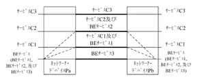
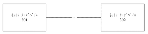
図1に示されるように、3つのサービスC1、C2及びC3は、ネットワーク・デバイスPaとネットワーク・デバイスPbとの間で伝送され、夫々のサービスは、指定されたタイムスロット帯域幅を占有する。例えば、サービスC1は2つのタイムスロットを占有し、それら2つのタイムスロットはサービスC2及びC3又は他のサービスによって共有され得ない。同じことはサービスC2及びC3にも当てはまる。それらのサービスが比較的低いトラフィックを有するパケット・サービス、例えば、比較的低いトラフィックを有するイーサネット・サービスである場合に、それらのサービスによって占有されるタイムスロットでは、大量のパケット間隔(Interpacket Gap,IPG)、例えば、アイドル(Idle)情報がネットワーク・デバイス間で伝送される。アイドル(Idle)情報は、実際には、サービスのデータ情報を運ばず、タイムスロット帯域幅リソースの無駄を生じさせる。 As shown in FIG. 1, three services C1, C2 and C3 are transmitted between the network device Pa and the network device Pb, each service occupying a designated timeslot bandwidth. For example, service C1 occupies two timeslots that cannot be shared by services C2 and C3 or other services. The same applies to services C2 and C3. If the services are packet services with relatively low traffic, eg Ethernet services with relatively low traffic, the timeslots occupied by these services may result in a large number of packet intervals (Interpacket Gap, IPG). ), for example, Idle information is transmitted between network devices. The Idle information does not actually carry the data information of the service, causing a waste of time slot bandwidth resources.
これを考慮して、本発明の実施形態は、フレキシブル・イーサネットのサービス伝送プロセスの間のタイムスロット・リソースの浪費が回避可能であるように、サービス送信方法及び装置、サービス受信方法及び装置、並びにネットワーク・システムを提供する。 In view of this, the embodiments of the present invention provide a service transmitting method and apparatus, a service receiving method and apparatus, and a service receiving method and apparatus so that waste of time slot resources during the flexible Ethernet service transmission process can be avoided. Provide a network system.
第1の態様に従って、本発明の実施形態は、ネットワーク・デバイスによって、第1データ・ストリーム及び第2データ・ストリームを含む少なくとも2つのデータ・ストリームを取得することと、第3データ・ストリームを生成するよう、前記第1データ・ストリームを前記第2データ・ストリームに挿入することと、前記第3データ・ストリームを送信することとを含み、前記第3データ・ストリームは、第1情報ブロック及び第2情報ブロックを含み、前記第1情報ブロック及び前記第2情報ブロックは、前記第2データ・ストリームから生成され、前記第1情報ブロックは、前記第1データ・ストリームを運ぶために使用され、前記第2情報ブロックは、第1データ・ストリーム分布表示マップを運ぶために使用され、前記第1データ・ストリーム分布表示マップは、前記第1情報ブロックの位置を示すために使用され、前記第2情報ブロックは、前もってセットされたマップ・ブロック・タイプを使用することによって特定される、サービス送信方法を提供する。本発明のこの実施形態において、第1データ・ストリームは、第2データ・ストリームを使用することによって運ばれ、それによって、帯域幅利用を改善する。第2データ・ストリームは、専用の帯域幅を有するサービスによって形成されてよく、第1データ・ストリームは、BE(Best Effort,ベスト・エフォート)サービスによって形成されてよい。サービスの統計多重化は、第2データ・ストリームのアイドル・タイムスロット・リソースを使用することによって、フレキシブル・イーサネットにおいて実装され得る。 According to a first aspect, embodiments of the present invention obtain, by a network device, at least two data streams including a first data stream and a second data stream and generate a third data stream. And inserting the first data stream into the second data stream and transmitting the third data stream, the third data stream comprising: Two information blocks, the first information block and the second information block are generated from the second data stream, the first information block is used to carry the first data stream, and The second information block is used to carry a first data stream distribution indication map, the first data stream distribution indication map is used to indicate the position of the first information block, and the second information is used. Blocks provide a service transmission method identified by using a preset map block type. In this embodiment of the invention, the first data stream is carried by using the second data stream, thereby improving bandwidth utilization. The second data stream may be formed by a service having a dedicated bandwidth, and the first data stream may be formed by a BE (Best Effort) service. Statistical multiplexing of services can be implemented in Flexible Ethernet by using the idle timeslot resource of the second data stream.
可能な実施において、当該方法は、前記第2データ・ストリームを取得し、該第2データ・ストリームにおいて少なくとも2つのアイドル・ブロックを特定し、該少なくとも2つのアイドル・ブロックの位置で前記第1情報ブロック及び前記第2情報ブロックを生成することを更に含む。第2データ・ストリームにおけるアイドル・ブロックが特定され、第1データ・ストリーム及び第1データ・ストリーム分布表示マップを運ぶために使用され、それによって、アイドル・タイムスロット・リソースを十分に活用する。任意に、他の冗長な情報ブロック、例えば、ERRORブロックが更に特定されてよく、それによって、冗長なタイムスロット・リソースを更に活用する。 In a possible implementation, the method obtains said second data stream, identifies at least two idle blocks in said second data stream, said first information at the position of said at least two idle blocks. The method further includes generating a block and the second information block. Idle blocks in the second data stream are identified and used to carry the first data stream and the first data stream distribution map, thereby fully utilizing idle time slot resources. Optionally, other redundant information blocks, eg, ERROR blocks, may be further specified, thereby further utilizing redundant time slot resources.
可能な実施において、前記少なくとも2つのアイドル・ブロックの位置で前記第1情報ブロック及び前記第2情報ブロックを生成することは、前記第1データ・ストリームを前記第1情報ブロックに挿入することと、前記第1情報ブロックの位置に基づき前記第1データ・ストリーム分布表示マップを生成し、該第1データ・ストリーム分布表示マップを前記第2情報ブロックに挿入することとを含む。任意に、第1データ・ストリームが最初に第1情報ブロックに挿入されてよく、次いで、第1データ・ストリーム分布表示マップが生成される。あるいは、第1データ・ストリーム分布表示マップが最初に生成されてよく、次いで、第1データ・ストリームが第1情報ブロックに挿入される。第1情報ブロックの位置は、第1データ・ストリーム分布表示マップを使用することによって示されてよく、それにより、受信端デバイスは第1データ・ストリームを第3データ・ストリームから抽出する。 In a possible implementation, generating the first information block and the second information block at the positions of the at least two idle blocks comprises inserting the first data stream into the first information block, Generating the first data stream distribution display map based on the position of the first information block and inserting the first data stream distribution display map into the second information block. Optionally, the first data stream may be first inserted in the first information block and then the first data stream distribution display map is generated. Alternatively, the first data stream distribution map may be generated first and then the first data stream is inserted into the first information block. The location of the first information block may be indicated by using the first data stream distribution map so that the receiving end device extracts the first data stream from the third data stream.
可能な実施において、前記第2データ・ストリームにおいて少なくとも2つのアイドル・ブロックを特定することは、前記第2データ・ストリームから第1セグメント・データ・ストリームを取得し、該第1セグメント・データ・ストリームにおいてアイドル・ブロックを特定して少なくとも2つのアイドル・ブロックを得ることを含み、前記アイドル・ブロックは、アイドル・ブロック・タイプを運ぶ。第2データ・ストリームはセグメントにおいて処理され、第1データ・ストリームはセグメントにおいて挿入され得、それによって、処理遅延を低減する。 In a possible implementation, identifying at least two idle blocks in the second data stream obtains a first segment data stream from the second data stream, And identifying an idle block to obtain at least two idle blocks, the idle block carrying an idle block type. The second data stream may be processed in the segment and the first data stream may be inserted in the segment, thereby reducing processing delay.
可能な実施において、前記第2データ・ストリームにおいて少なくとも2つのアイドル・ブロックを特定した後に、当該方法は、前記少なくとも2つのアイドル・ブロックの位置及び/又は非アイドル・ブロックの位置を示すために使用されるアイドル・ブロック分布表示マップを生成することと、前記アイドル・ブロック分布表示マップに基づき前記第1データ・ストリーム分布表示マップを生成することとを更に含む。 In a possible implementation, after identifying at least two idle blocks in the second data stream, the method is used for indicating the position of the at least two idle blocks and/or the position of non-idle blocks. Further comprising: generating an idle block distribution display map that is performed; and generating the first data stream distribution display map based on the idle block distribution display map.
可能な実施において、当該方法は、前記第2データ・ストリームから第2セグメント・データ・ストリームを取得し、該第2セグメント・データ・ストリームにおいて少なくとも2つのアイドル・ブロックを特定し、該少なくとも2つのアイドル・ブロックの位置で前記第1情報ブロック及び前記第2情報ブロックを生成することと、前もってセットされた関与情報を使用することによって前記第2セグメント・データ・ストリームの位置を示すこととを更に含む。第1データ・ストリームが挿入され得る位置、又は第1データ・ストリームが挿入され得ない位置は、マスキングのような方法で示されることができ、それによって、第1データ・ストリームの十分な挿入を実施する。 In a possible implementation, the method obtains a second segment data stream from the second data stream, identifies at least two idle blocks in the second segment data stream, and determines the at least two idle blocks. Generating the first information block and the second information block at the location of an idle block and indicating the location of the second segment data stream by using preset engagement information. Including. The positions where the first data stream can be inserted, or where the first data stream cannot be inserted, can be indicated in a masking-like manner, thereby ensuring sufficient insertion of the first data stream. carry out.
可能な実施において、当該方法は、前記第2情報ブロックの位置を前記第1セグメント・データ・ストリーム又は前記第2セグメント・データ・ストリームにおける第1位置に調整することを更に含む。第2情報ブロックの位置、第1セグメント・データ・ストリーム、又は第2セグメント・データ・ストリームは再配置され、それにより、受信端デバイスのデータ再生効率は改善され得る。 In a possible implementation, the method further comprises adjusting the position of the second information block to the first position in the first segment data stream or the second segment data stream. The position of the second information block, the first segment data stream, or the second segment data stream may be rearranged, thereby improving the data reproduction efficiency of the receiving end device.
第2の態様に従って、本発明の実施形態は、ネットワーク・デバイスによって、第3データ・ストリームを受信することと、前記第3データ・ストリームから第1データ・ストリームを抽出し、前記第3データ・ストリームを第2データ・ストリームへリストアすることとを含み、前記第3データ・ストリームは、第1情報ブロック及び第2情報ブロックを含み、前記第2データ・ストリームは、前記第1情報ブロック及び前記第2情報ブロックを使用することによってリストアされ、前記第1情報ブロックは、前記第1データ・ストリームを運ぶために使用され、前記第2情報ブロックは、第1データ・ストリーム分布表示マップを運ぶために使用され、前記第1データ・ストリーム分布表示マップは、前記第1情報ブロックの位置を示すために使用され、前記第2情報ブロックは、前もってセットされたマップ・ブロック・タイプを使用することによって特定される、サービス受信方法を提供する。本発明のこの実施形態において、第1データ・ストリームは第3データ・ストリームから抽出され、第3データ・ストリームは第2データ・ストリームへリストアされ、それによって、帯域幅利用を改善する。第2データ・ストリームは、専用の帯域幅を有するサービスによって形成されてよく、第1データ・ストリームは、BEサービスによって形成されてよい。サービスの統計多重化は、第2データ・ストリームのアイドル・タイムスロット・リソースを使用することによって、フレキシブル・イーサネットにおいて実装され得る。 According to a second aspect, embodiments of the present invention provide a network device for receiving a third data stream and extracting a first data stream from the third data stream, the third data stream comprising: Restoring the stream to a second data stream, the third data stream including a first information block and a second information block, and the second data stream including the first information block and the first information block. Restored by using a second information block, the first information block is used to carry the first data stream, and the second information block is used to carry a first data stream distribution indicator map. , The first data stream distribution display map is used to indicate the position of the first information block, and the second information block is used by using a preset map block type. Provide a specified service reception method. In this embodiment of the invention, the first data stream is extracted from the third data stream and the third data stream is restored to the second data stream, thereby improving bandwidth utilization. The second data stream may be formed by a service having a dedicated bandwidth and the first data stream may be formed by a BE service. Statistical multiplexing of services can be implemented in Flexible Ethernet by using the idle timeslot resource of the second data stream.
可能な実施において、前記第3データ・ストリームから第1データ・ストリームを抽出することは、前記第3データ・ストリームから第1セグメント・データ・ストリーム又は第2セグメント・データ・ストリームを取得することと、前記第1セグメント・データ・ストリーム又は前記第2セグメント・データ・ストリームにおいて前記第2情報ブロックを特定し、該第2情報ブロックから第1データ・ストリーム分布表示マップを取得することと、前記第1データ・ストリーム分布表示マップに基づき前記第1情報ブロックから前記第1データ・ストリームを取得することとを含む。第3データ・ストリームはセグメントにおいて処理され、第1データ・ストリームはセグメントにおいて挿入され得、それによって、処理遅延を低減する。第1情報ブロックの位置は、第1データ・ストリーム分布表示マップを使用することによって示されてよく、それにより、受信端デバイスは、第3データ・ストリームから第1データ・ストリームを抽出する。 In a possible implementation, extracting the first data stream from the third data stream comprises obtaining a first segment data stream or a second segment data stream from the third data stream. Identifying the second information block in the first segment data stream or the second segment data stream and obtaining a first data stream distribution display map from the second information block; Acquiring the first data stream from the first information block based on a one data stream distribution map. The third data stream may be processed in the segment and the first data stream may be inserted in the segment, thereby reducing processing delay. The location of the first information block may be indicated by using the first data stream distribution indicator map, so that the receiving end device extracts the first data stream from the third data stream.
可能な実施において、当該方法は、前記第2セグメント・データ・ストリームの位置を示す前もってセットされた関与情報を取得し、該前もってセットされた関与情報に基づき前記第3データ・ストリームから前記第2セグメント・データ・ストリームを取得することと、該第2セグメント・データ・ストリームから前記第1データ・ストリームを取得することとを更に含む。第1データ・ストリームが抽出され得る位置、又は第1データ・ストリームが抽出され得ない位置は、マスキングのような方法で示されることができ、それによって、第1データ・ストリームの柔軟な抽出を実施する。 In a possible implementation, the method obtains preset engagement information indicating the position of the second segment data stream and based on the preset engagement information, the second data stream from the third data stream. The method further comprises obtaining a segment data stream and obtaining the first data stream from the second segment data stream. The locations where the first data stream can be extracted or where the first data stream cannot be extracted can be indicated in a masking-like manner, thereby allowing flexible extraction of the first data stream. carry out.
可能な実施において、前記第3データ・ストリームから第1データ・ストリームを抽出することは、前記第1データ・ストリーム分布表示マップを前記第1セグメント・データ・ストリーム又は前記第2セグメント・データ・ストリームにおける第1の位置から取得することを含む。第2情報ブロックの位置、第1セグメント・データ・ストリーム、又は第2セグメント・データ・ストリームは再配置され、それにより、受信端デバイスのデータ再生効率は改善され得る。 In a possible implementation, extracting the first data stream from the third data stream is performed by using the first data stream distribution display map as the first segment data stream or the second segment data stream. Acquiring from a first position in. The position of the second information block, the first segment data stream, or the second segment data stream may be rearranged, thereby improving the data reproduction efficiency of the receiving end device.
可能な実施において、前記第1データ・ストリーム分布表示マップは、第1のビットを使用することによって前記第1情報ブロックの位置を特定する。 In a possible implementation, the first data stream distribution indicator map locates the first information block by using a first bit.
可能な実施において、前記第2データ・ストリームが前記第1情報ブロック及び前記第2情報ブロックを使用することによってリストアされることは、前記第1情報ブロック及び第2情報ブロックの位置で少なくとも2つのアイドル・ブロックを生成することを含み、前記アイドル・ブロックは、アイドル・ブロック・タイプを運ぶ。 In a possible implementation, the second data stream being restored by using the first information block and the second information block means that at least two positions at the first information block and the second information block are present. Including generating an idle block, said idle block carrying an idle block type.
第3の態様に従って、本発明の実施形態は、第1データ・ストリーム及び第2データ・ストリームを含む少なくとも2つのデータ・ストリームを取得するよう構成される取得モジュールと、第3データ・ストリームを生成するよう、前記第1データ・ストリームを前記第2データ・ストリームに挿入するよう構成される処理モジュールと、前記第3データ・ストリームを送信するよう構成される送信モジュールとを含み、前記第3データ・ストリームは、第1情報ブロック及び第2情報ブロックを含み、前記第1情報ブロック及び前記第2情報ブロックは、前記第2データ・ストリームから生成され、前記第1情報ブロックは、前記第1データ・ストリームを運ぶために使用され、前記第2情報ブロックは、第1データ・ストリーム分布表示マップを運ぶために使用され、前記第1データ・ストリーム分布表示マップは、前記第1情報ブロックの位置を示すために使用され、前記第2情報ブロックは、前もってセットされたマップ・ブロック・タイプを使用することによって特定される、サービス送信装置を提供する。本発明のこの実施形態において、第1データ・ストリームは、第2データ・ストリームを使用することによって運ばれ、それによって、帯域幅利用を改善する。第2データ・ストリームは、専用の帯域幅を有するサービスによって形成されてよく、第1データ・ストリームは、BEサービスによって形成されてよい。サービスの統計多重化は、第2データ・ストリームのアイドル・タイムスロット・リソースを使用することによって、フレキシブル・イーサネットにおいて実装され得る。 According to a third aspect, embodiments of the present invention generate an acquisition module configured to acquire at least two data streams including a first data stream and a second data stream, and generating a third data stream. And a processing module configured to insert the first data stream into the second data stream and a transmission module configured to transmit the third data stream, the third data stream comprising: The stream includes a first information block and a second information block, the first information block and the second information block are generated from the second data stream, and the first information block is the first data Used to carry a stream, the second information block is used to carry a first data stream distribution map, the first data stream distribution map maps the location of the first information block. Used to indicate, the second information block provides a service transmitter identified by using a preset map block type. In this embodiment of the invention, the first data stream is carried by using the second data stream, thereby improving bandwidth utilization. The second data stream may be formed by a service having a dedicated bandwidth and the first data stream may be formed by a BE service. Statistical multiplexing of services can be implemented in Flexible Ethernet by using the idle timeslot resource of the second data stream.
第1の態様における方法の実施形態は、第3の態様における装置の実施形態を使用することによって実施可能である。 The method embodiment of the first aspect can be implemented by using the apparatus embodiment of the third aspect.
可能な実施において、前記処理モジュールは、前記第2データ・ストリームを取得し、該第2データ・ストリームにおいて少なくとも2つのアイドル・ブロックを特定し、該少なくとも2つのアイドル・ブロックの位置で前記第1情報ブロック及び前記第2情報ブロックを生成するよう更に構成される。 In a possible implementation, the processing module obtains the second data stream, identifies at least two idle blocks in the second data stream, and the first at the location of the at least two idle blocks. It is further configured to generate an information block and the second information block.
可能な実施において、前記処理モジュールは、前記第1データ・ストリームを前記第1情報ブロックに挿入し、前記第1情報ブロックの位置に基づき前記第1データ・ストリーム分布表示マップを生成し、該第1データ・ストリーム分布表示マップを前記第2情報ブロックに挿入するよう構成される。 In a possible implementation, the processing module inserts the first data stream into the first information block, generates the first data stream distribution display map based on the position of the first information block, A one data stream distribution display map is configured to be inserted into the second information block.
可能な実施において、前記処理モジュールは、前記第2データ・ストリームから第1セグメント・データ・ストリームを取得し、該第1セグメント・データ・ストリームにおいてアイドル・ブロックを特定して少なくとも2つのアイドル・ブロックを得るよう構成され、前記アイドル・ブロックは、アイドル・ブロック・タイプを運ぶ。 In a possible implementation, the processing module obtains a first segment data stream from the second data stream and identifies an idle block in the first segment data stream to identify at least two idle blocks. And the idle block carries an idle block type.
可能な実施において、前記処理モジュールは、前記少なくとも2つのアイドル・ブロックの位置及び/又は非アイドル・ブロックの位置を示すために使用されるアイドル・ブロック分布表示マップを生成し、前記アイドル・ブロック分布表示マップに基づき前記第1データ・ストリーム分布表示マップを生成するよう更に構成される。 In a possible implementation, the processing module generates an idle block distribution display map used to indicate the positions of the at least two idle blocks and/or the positions of non-idle blocks, and the idle block distribution map. It is further configured to generate the first data stream distribution display map based on the display map.
可能な実施において、前記処理モジュールは、前記第2データ・ストリームから第2セグメント・データ・ストリームを取得し、該第2セグメント・データ・ストリームにおいて少なくとも2つのアイドル・ブロックを特定し、該少なくとも2つのアイドル・ブロックの位置で前記第1情報ブロック及び前記第2情報ブロックを生成し、且つ、前もってセットされた関与情報を使用することによって前記第2セグメント・データ・ストリームの位置を示すよう更に構成される。 In a possible implementation, the processing module obtains a second segment data stream from the second data stream and identifies at least two idle blocks in the second segment data stream, the at least two Further configured to generate the first information block and the second information block at the position of one idle block and to indicate the position of the second segment data stream by using preset engagement information. To be done.
可能な実施において、前記処理モジュールは、前記第2情報ブロックの位置を前記第1セグメント・データ・ストリーム又は前記第2セグメント・データ・ストリームにおける第1の位置に調整するよう更に構成される。 In a possible implementation, the processing module is further configured to adjust the position of the second information block to a first position in the first segment data stream or the second segment data stream.
第4の態様に従って、本発明の実施形態は、第3データ・ストリームを受信するよう構成される受信モジュールと、前記第3データ・ストリームから第1データ・ストリームを抽出し、前記第3データ・ストリームを第2データ・ストリームへリストアするよう構成される処理モジュールとを含み、前記第3データ・ストリームは、第1情報ブロック及び第2情報ブロックを含み、前記第2データ・ストリームは、前記第1情報ブロック及び前記第2情報ブロックを使用することによってリストアされ、前記第1情報ブロックは、前記第1データ・ストリームを運ぶために使用され、前記第2情報ブロックは、第1データ・ストリーム分布表示マップを運ぶために使用され、前記第1データ・ストリーム分布表示マップは、前記第1情報ブロックの位置を示すために使用され、前記第2情報ブロックは、前もってセットされたマップ・ブロック・タイプを使用することによって特定される、サービス受信装置を提供する。本発明のこの実施形態において、第1データ・ストリームは第3データ・ストリームから抽出され、第3データ・ストリームは第2データ・ストリームへリストアされ、それによって、帯域幅利用を改善する。第2データ・ストリームは、専用の帯域幅を有するサービスによって形成されてよく、第1データ・ストリームは、BEサービスによって形成されてよい。サービスの統計多重化は、第2データ・ストリームのアイドル・タイムスロット・リソースを使用することによって、フレキシブル・イーサネットにおいて実装され得る。 According to a fourth aspect, an embodiment of the invention comprises a receiving module configured to receive a third data stream, extracting a first data stream from the third data stream, the third data stream. A processing module configured to restore the stream to a second data stream, the third data stream including a first information block and a second information block, and the second data stream including the second information block. Restored by using one information block and the second information block, the first information block being used to carry the first data stream, and the second information block being the first data stream distribution Used to carry a display map, the first data stream distribution display map is used to indicate the location of the first information block, and the second information block is a preset map block type To provide a service receiving device specified by using. In this embodiment of the invention, the first data stream is extracted from the third data stream and the third data stream is restored to the second data stream, thereby improving bandwidth utilization. The second data stream may be formed by a service having a dedicated bandwidth and the first data stream may be formed by a BE service. Statistical multiplexing of services can be implemented in Flexible Ethernet by using the idle timeslot resource of the second data stream.
第2の態様における方法の実施形態は、第4の態様における装置の実施形態を使用することによって実施可能である。 Embodiments of the method in the second aspect can be implemented by using the apparatus embodiments in the fourth aspect.
可能な実施において、前記処理モジュールは、前記第3データ・ストリームから第1セグメント・データ・ストリーム又は第2セグメント・データ・ストリームを取得し、前記第1セグメント・データ・ストリーム又は前記第2セグメント・データ・ストリームにおいて前記第2情報ブロックを特定し、該第2情報ブロックから第1データ・ストリーム分布表示マップを取得し、前記第1データ・ストリーム分布表示マップに基づき前記第1情報ブロックから前記第1データ・ストリームを取得するよう構成される。 In a possible implementation, the processing module obtains a first segment data stream or a second segment data stream from the third data stream, the first segment data stream or the second segment data stream. The second information block is specified in the data stream, a first data stream distribution display map is obtained from the second information block, and the first data block distribution display map is obtained from the first information block based on the first data stream distribution display map It is configured to obtain one data stream.
可能な実施において、前記処理モジュールは、前もってセットされた関与情報を取得し、該前もってセットされた関与情報に基づき前記第3データ・ストリームから前記第2セグメント・データ・ストリームを取得するよう更に構成され、前記前もってセットされた関与情報は、前記第2セグメント・データ・ストリームの位置を示す。 In a possible implementation, the processing module is further configured to obtain preset engagement information and obtain the second segment data stream from the third data stream based on the preset engagement information. And the preset engagement information indicates the position of the second segment data stream.
可能な実施において、前記処理モジュールは、前記第1データ・ストリーム分布表示マップを前記第1セグメント・データ・ストリーム又は前記第2セグメント・データ・ストリームにおける第1の位置から取得するよう更に構成される。 In a possible implementation, the processing module is further configured to obtain the first data stream distribution map from a first position in the first segment data stream or the second segment data stream. ..
可能な実施において、前記第1データ・ストリーム分布表示マップは、第1のビットを使用することによって前記第1情報ブロックの位置を特定する。 In a possible implementation, the first data stream distribution indicator map locates the first information block by using a first bit.
可能な実施において、前記処理モジュールは、前記第1情報ブロック及び第2情報ブロックの位置で少なくとも2つのアイドル・ブロックを生成するよう構成され、前記アイドル・ブロックは、アイドル・ブロック・タイプを運ぶ。 In a possible implementation, the processing module is configured to generate at least two idle blocks at positions of the first information block and the second information block, the idle blocks carrying idle block types.
第5の態様に従って、本発明の実施形態は、第3の態様及び第3の態様のいずれかの可能な実施における装置と、第4の態様及び第4の態様のいずれかの可能な実施における装置とを含むネットワーク・システムを提供する。 According to a fifth aspect, an embodiment of the present invention is a device in any possible implementation of the third aspect and the third aspect and in any possible implementation of the fourth aspect and the fourth aspect. And a network system including a device.
第6の態様に従って、本発明の実施形態は、プロセッサ、メモリ、及び少なくとも1つのネットワーク・インターフェイスを含むネットワーク・デバイスを提供する。メモリは、コンピュータ実行可能命令を記憶するよう構成され、ネットワーク・デバイスが作動する場合に、プロセッサは、メモリに記憶されているコンピュータ実行可能命令を実行し、それにより、ネットワーク・デバイスは、第1の態様及び第1の態様のいずれかの可能な実施における方法を実行する。 According to a sixth aspect, embodiments of the present invention provide a network device including a processor, memory and at least one network interface. The memory is configured to store computer-executable instructions, and when the network device operates, the processor executes the computer-executable instructions stored in the memory, thereby causing the network device to perform the first operation. And the method in any possible implementation of the first aspect.
第7の態様に従って、本発明の実施形態は、プロセッサ、メモリ、及び少なくとも1つのネットワーク・インターフェイスを含むネットワーク・デバイスを提供する。メモリは、コンピュータ実行可能命令を記憶するよう構成され、ネットワーク・デバイスが作動する場合に、プロセッサは、メモリに記憶されているコンピュータ実行可能命令を実行し、それにより、ネットワーク・デバイスは、第2の態様及び第2の態様のいずれかの可能な実施における方法を実行する。
According to a seventh aspect, embodiments of the present invention provide a network device including a processor, memory and at least one network interface. The memory is configured to store computer-executable instructions, and the processor executes the computer-executable instructions stored in the memory when the network device operates, thereby causing the network device to execute the second instruction. Carrying out the method in a possible implementation of any of the
本発明の実施形態における又は先行技術における技術的解決法をより明りょうに記載するよう、以下は、背景及び実施形態を記載するために必要とされる添付の図面について簡単に説明する。 To describe the technical solutions in the embodiments of the present invention or in the prior art more clearly, the following briefly describes the background and the accompanying drawings required for describing the embodiments.
本発明の目的、技術的解決法、及び利点をより明りょうに且つより理解しやすくするよう、以下は、添付の図面及び実施形態を参照して詳細に本願を更に記載する。 In order to make the objects, technical solutions and advantages of the present invention clearer and easier to understand, the following further describes the present application in detail with reference to the accompanying drawings and embodiments.
本発明の実施形態で提供される技術的解決法は、フレキシブル・イーサネットに適用されてよく、他のタイプのネットワーク、例えば、イーサネット、光伝達網(Optical Transport Network,OTN)ネットワーク、及び同期デジタル階層(Synchronous Digital Hierarchy,SDH)ネットワークにも適用されてよい。本発明の実施形態においては、フレキシブル・イーサネットが、説明のための例として主に使用される。 The technical solution provided in the embodiments of the present invention may be applied to Flexible Ethernet, and other types of networks such as Ethernet, Optical Transport Network (OTN) network, and Synchronous Digital Hierarchy. (Synchronous Digital Hierarchy, SDH) network may also be applied. In the embodiments of the present invention, Flexible Ethernet is mainly used as an example for explanation.
図2は、本発明の実施形態に従うフレキシブル・イーサネットのサービス伝送の概略図である。図2に示されるように、ネットワーク・デバイスPa及びPbは3つのサービスC1、C2及びC3を伝送する。3つのサービスを伝送するために使用されるネットワーク・デバイスPa及びPbにおける物理インターフェイスは、100Gフレキシブル・イーサネット物理インターフェイスであり、物理インターフェイスは、5Gの細かさで20個のタイムスロットに分割される、と想定される。サービスC1の帯域幅は10Gであり、2つのタイムスロット、すなわち、タイムスロット1及びタイムスロット2を占有する。サービスC2の帯域幅は25Gであり、5つのタイムスロット、すなわち、タイムスロット3乃至タイムスロット7を占有する。サービスC3の帯域幅は25Gであり、5つのタイムスロット、すなわち、タイムスロット8乃至タイムスロット12を占有する。サービスC1及びC2がパケット・サービス、例えば、イーサネット・サービスである場合に、サービスC1及びC2はアイドル情報を含む可能性がある。アイドル情報は、サービスのデータ情報を含まず、アイドル情報によって占有されるタイムスロットは、アイドル・タイムスロットであり、タイムスロット・リソースの無駄を生じさせる。従って、本発明のこの実施形態において、サービスのアイドル情報によって占有されるアイドル・タイムスロットは、使用される他のサービス、例えば、ベスト・エフォート(Best Effort,BE)サービスと共有されてよい。図2において、BEサービスは、サービスC1及びサービスC2におけるアイドル・タイムスロットを使用することによって、伝送されてよい。具体的に言えば、BEサービス(BEサービス1)及びサービスC1は、タイムスロット1及びタイムスロット2を共有し、BEサービス(BEサービス2)及びサービスC2は、タイムスロット3乃至タイムスロット7を共有する。任意に、図3に示されるように、BEサービスのために、あるもの(BEサービス3)は、専用のタイムスロット、例えば、他のサービスに割り当てられていないタイムスロット13乃至タイムスロット20を使用してよく、あるもの(BEサービス1及びBEサービス2)は、サービスC1及びC2のアイドル・タイムスロットを使用する。本発明のこの実施形態におけるBEサービスは、フレキシブル・イーサネット・サービス、パケット・サービス(例えば、イーサネット・サービス)、インターネット・プロトコル(Internet Protocol,IP)サービス、ファイバ・チャネル(Fibre Channel,FC)サービス、インフィニバンド(InfiniBand)サービス、又は同様のものであってよい。BEサービスは、一般に、比較的低い優先度を有している。より高い優先度のサービスがネットワーク内にある場合に、BEサービスの伝送帯域幅は必ずしも確保されず、BEサービスの伝送帯域幅は、できる限りの努力により確保され得る。従って、BEサービスは、ネットワーク・リソース利用を改善するよう、より高い優先度の他のサービスのアイドル・タイムスロット又はアイドル帯域幅を使用することによって搬送及び伝送されてよい。
FIG. 2 is a schematic diagram of flexible Ethernet service transmission according to an embodiment of the present invention. As shown in FIG. 2, the network devices Pa and Pb carry three services C1, C2 and C3. The physical interface in the network devices Pa and Pb used to carry the three services is a 100G Flexible Ethernet physical interface, the physical interface is divided into 20 time slots with 5G granularity, Is assumed. The bandwidth of service C1 is 10G and occupies two time slots, namely
サービスがフレキシブル・イーサネット物理インターフェイス上で伝送される場合に、フレキシブル・イーサネット・データ・フレーム・フォーマットによるコード・ブロック・ストリームが形成される。例えば、100Gフレキシブル・イーサネット物理インターフェイスは、5Gの細かさで20個のタイムスロットに分割されてよい。図4に示されるように、100Gフレキシブル・イーサネット物理インターフェイス上で形成されるフレキシブル・イーサネット・データ・フレームの構造は、行ごとに(1+20×1023)個のコード・ブロックを有して、8つの行を含む。データ・フレーム構造において、1つの行はサブフレームを形成し、8つの行は基本フレームを形成し、32個の行はスーパーフレームを形成する。コード・ブロックは、ここでは、64B/66Bコード・ブロックであってよい。各行における最初のコード・ブロックはオーバーヘッド・ブロックであり、他の20×1023個のコード・ブロックはペイロード・ブロックである。各行におけるペイロード・ブロックは、20個のコード・ブロックを1つの単位として使用することによって1023個のセグメントに分割されてよく、各セグメントにおける20個のコード・ブロックは、20個のタイムスロットに夫々対応する。例えば、各セグメントにおいて、識別子が1であるコード・ブロックは、タイムスロット1に対応し、識別子が2であるコード・ブロックは、タイムスロット2に対応し、・・・そして、識別子が20であるコード・ブロックは、タイムスロット20に対応する。フレキシブル・イーサネット・データ・フレーム全体は、8つの行に分かれたペイロード・ブロックを含む。識別子が1であるコード・ブロックの各列は、タイムスロット1に対応し、識別子が2であるコード・ブロックの各列は、タイムスロット2に対応し、・・・そして、識別子が20であるコード・ブロックの各列は、タイムスロット20に対応する。本発明のこの実施形態において、タイムスロットはTDM伝送時間スライスであり、1つのフレキシブル・イーサネット・データ・フレームにおけるコード・ブロックの複数列の位置に対応してよく、あるいは、複数の連続したフレキシブル・イーサネット・データ・フレームにおけるコード・ブロックの複数列の位置に対応してよい。
A code block stream according to the Flexible Ethernet data frame format is formed when the service is carried on the Flexible Ethernet physical interface. For example, a 100G Flexible Ethernet physical interface may be divided into 20 time slots with 5G granularity. As shown in FIG. 4, the structure of the flexible Ethernet data frame formed on the 100G flexible Ethernet physical interface has eight (1+20×1023) code blocks for each row. Contains lines. In the data frame structure, one row forms a subframe, eight rows form a basic frame, and 32 rows form a superframe. The code block may here be a 64B/66B code block. The first code block in each row is an overhead block and the other 20×1023 code blocks are payload blocks. The payload block in each row may be divided into 1023 segments by using 20 code blocks as a unit, where the 20 code blocks in each segment are in 20 time slots respectively. Correspond. For example, in each segment, the code block with the
最初の行の最初のコード・ブロックは、データ・フレーム全体の最初のオーバーヘッド・ブロックである。図5aに示されるように、オーバーヘッド・ブロックは、コントロール・ブロック・タイプ“0x4B”に加えて、この位置がフレキシブル・イーサネット・データ・フレームの最初のオーバーヘッド・ブロックであることを示すために使用される“0x5”を含む。
The first block of code in the first row is the first overhead block of the entire data frame. As shown in FIG. 5a, the overhead block is used to indicate that this position is the first overhead block of the flexible Ethernet data frame in addition to the control block type “0x4B”. " 0x5 " is included.
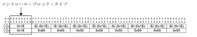
ペイロード・ブロックのブロック・タイプは、コントロール・ブロック及びデータ・ブロックを含み、コントロール・ブロック及びデータ・ブロックは、ブロック・タイプを使用することによって特定されてよい。ブロック・タイプは2ビット同期ヘッダ(Sync Header)を含んでよい。“01b”は、続く8つのオクテットがデータ文字であり、ブロック・タイプがデータ・ブロックであることを示す。“10b”は、続く文字がコントロール文字及び/又はデータ文字であり、ブロック・タイプがコントロール・ブロックであることを示す。更に、コントロール・ブロック・タイプは、コントロール・ブロックにおけるコントロール・ブロック・タイプ・フィールドを使用することによって特定されてよく、先行技術では全部で15個のコントロール・ブロック・タイプがある。本発明のこの実施形態において、アイドル・ブロックの特定及び処理に関して、アイドル・ブロックは、コントロール・ブロックの一種である。アイドル・ブロックはアイドル情報を運び、アイドル情報は実際には冗長な情報である。アイドル・ブロックは、物理インターフェイスがあるサービス専用であるときに、比較的低いサービス・トラフィックの場合において、そのサービスの論理ポートのためのパディング帯域幅である。論理ポートはいくつかのタイムスロットを含むと考えられてよい。論理ポートがアイドル・ブロックによりパディングされるとき、アイドル・ブロックに対応するタイムスロットはアイドル・タイムスロットである。アイドル・ブロックは、特定のコントロール・ブロック・タイプを使用することによって特定されてよい。図5bに示されるコード・ブロック・フォーマットの概略図において、第1及び第2のビットは、コード・ブロックがコントロール・ブロックであることを示す同期ヘッダ“01”である。コントロール・ブロック・タイプ“0x1E”によって特定され得るコントロール・ブロック・タイプは、エラー表示ブロック及びアイドル・ブロックを含む。エラー表示ブロックにおいて、コントロール・ブロック・タイプは、7ビットに圧縮された全ての“0x1E”が後に続く。アイドル・ブロックにおいて、コントロール・ブロック・タイプは、7ビットに圧縮された全ての“0x00”が後に続く。 The block type of the payload block includes a control block and a data block, and the control block and the data block may be identified by using the block type. The block type may include a 2-bit Sync Header. "01b" indicates that the following 8 octets are a data character and the block type is a data block. "10b" indicates that the following character is a control character and/or a data character, and the block type is a control block. Further, the control block type may be identified by using the control block type field in the control block, there being a total of 15 control block types in the prior art. In this embodiment of the invention, an idle block is a type of control block in terms of idle block identification and processing. The idle block carries idle information, which is actually redundant information. An idle block is the padding bandwidth for a logical port of a service when the physical interface is dedicated to that service and in the case of relatively low service traffic. A logical port may be considered to include several time slots. When a logical port is padded with idle blocks, the timeslots corresponding to the idle blocks are idle timeslots. Idle blocks may be identified by using a particular control block type. In the code block format schematic shown in FIG. 5b, the first and second bits are a sync header "01" indicating that the code block is a control block. The control block types that can be specified by the control block type “0x1E” include an error indication block and an idle block. In the error indication block, the control block type is followed by all "0x1E" compressed to 7 bits. In the idle block, the control block type is followed by all "0x00" compressed to 7 bits.
本発明のこの実施形態において、フレキシブル・イーサネット物理インターフェイスがフレキシブル・イーサネット・データ・フレーム・フォーマットによりサービスを伝送するために使用されることは、記載のための例として使用される。最初に、フレキシブル・イーサネット物理インターフェイスを使用することによってサービス多重化を実装するプロセスが記載される。図6に示されるように、2つのサービスC1及びC2は、4つの100GE物理インターフェイスをカスケード接続することによって形成された400Gフレキシブル・イーサネット物理インターフェイス・グループ上で多重化される。400Gフレキシブル・イーサネット物理インターフェイス・グループは、5Gの細かさで80個のタイムスロットに分割されてよく、夫々の100GE物理インターフェイスは、5Gの細かさで20個のタイムスロットに分割されてよい。サービスC1の帯域幅は10Gであり、2つのタイムスロットを占有し、サービスC2の帯域幅は25Gであり、5つのタイムスロットを占有する、と想定される。2つのサービスC1及びC2は、80個のタイムスロット・ストリームにおいてそれらの各々の占有されたタイムスロットに分配され、次いで、80個のタイムスロット・ストリームは、400Gフレキシブル・イーサネット物理インターフェイス・グループにおける対応する物理インターフェイスへ別々に送られる。例えば、サービスC1は、サービスC1によって占有される2つのタイムスロットに分配された後、フレキシブル・イーサネット物理インターフェイスAへ送られ、サービスC2は、サービスC2によって占有される5つのタイムスロットに分配された後、フレキシブル・イーサネット物理インターフェイスB及びCへ送られる。すなわち、サービスC1は、物理インターフェイスAを使用することによって物理リンクへ伝送され、サービスC2は、物理インターフェイスB及びCを使用することによって物理リンクへ伝送される。本発明のこの実施形態において、送信端ネットワーク・デバイスによって実行される方法は、上記のサービス多重化プロセスの間に実行されてよく、あるいは、サービス多重化プロセスの前又は後に実行されてもよい。確かに、本発明のこの実施形態は、上記のサービス多重化プロセスとの関連を有さなくてもよい。サービス多重化プロセス及び本発明のこの実施形態は、記載のために組み合わされ、これは、単に、記載のための例として使用されるにすぎない。 In this embodiment of the invention, the use of the Flexible Ethernet physical interface to carry services in the Flexible Ethernet data frame format is used as an example for description. First, the process of implementing service multiplexing by using the flexible Ethernet physical interface is described. As shown in FIG. 6, the two services C1 and C2 are multiplexed on a 400G Flexible Ethernet physical interface group formed by cascading four 100GE physical interfaces. A 400G Flexible Ethernet physical interface group may be divided into 80 time slots with 5G granularity, and each 100GE physical interface may be divided into 20 time slots with 5G granularity. It is assumed that the service C1 has a bandwidth of 10 G and occupies two time slots, and the service C2 has a bandwidth of 25 G and occupies five time slots. The two services C1 and C2 are distributed in their respective occupied timeslots in 80 timeslots streams, then 80 timeslots streams correspond to in the 400G flexible Ethernet physical interface group. Sent to the physical interface separately. For example, service C1 is distributed to two timeslots occupied by service C1 and then sent to flexible Ethernet physical interface A, and service C2 is distributed to five timeslots occupied by service C2. Later, it is sent to the flexible Ethernet physical interfaces B and C. That is, the service C1 is transmitted to the physical link by using the physical interface A, and the service C2 is transmitted to the physical link by using the physical interfaces B and C. In this embodiment of the invention, the method performed by the sending network device may be performed during the service multiplexing process described above, or it may be performed before or after the service multiplexing process. Indeed, this embodiment of the invention may have no relevance to the service multiplexing process described above. The service multiplexing process and this embodiment of the invention are combined for the purpose of description, which is merely used as an example for description.
図7は、本発明の実施形態に従うサービス送信方法のフローチャートの例である。方法は、フレキシブル・イーサネット・デバイス又はイーサネット・デバイスのようなネットワーク・デバイスによって実行されてよく、ネットワーク・デバイスは、送信端ネットワーク・デバイスであってよい。方法は次のステップを含む。 FIG. 7 is an example of a flowchart of a service transmission method according to an embodiment of the present invention. The method may be performed by a network device such as a flexible ethernet device or an ethernet device, which may be a sending end network device. The method includes the following steps.
S11.ネットワーク・デバイスは少なくとも1つのサービスを受信し、このとき、少なくとも1つのサービスは、ベスト・エフォートBEサービスを含む。 S11. The network device receives at least one service, where the at least one service comprises a best effort BE service.
少なくとも1つのサービスはBEサービスを含んでよく、更には、専用の帯域幅を有するサービス(例えば、図2のサービスC1、C2及びC3)を含んでよい。専用の帯域幅を有するサービスの優先度は、通常は、BEサービスのそれよりも高く、従って、ネットワーク・デバイスは、サービスの帯域幅要件に基づき、サービスを運ぶのに十分な帯域幅リソースを割り当て、そして、サービスの帯域幅要件が満足されることを確かにすることができる。例えば、専用の帯域幅を有するサービスはイーサネット・サービスであり、サービスはアイドル情報を含むことがある。アイドル情報はサービスのデータ情報を含まないが、依然としてタイムスロットを占有する必要があるので、アイドル・タイムスロット・リソースがもたらされる。この場合に、BEサービスは、専用の帯域幅を有するサービスのアイドル・タイムスロット・リソースを使用することによって、搬送及び伝送されてよい。しかし、専用の帯域幅を有するサービスのアイドル・タイムスロット・リソースの不確かさのために、それらのアイドル・タイムスロット・リソースがBEサービスの帯域幅要件を満足することができることは必ずしも確かにされず、帯域幅は、できる限りの努力によりBEサービスのために提供され得る。任意に、BEサービスは、専用の帯域幅を有するサービスによって解放された帯域幅を使用することによって、伝送されてもよい。BEサービスを受信した後、ネットワーク・デバイスは、BEサービスを一時的に保持してよく、専用の帯域幅を有するサービスが受信されるまではBEサービスに対してS12乃至S14を実行しない。 The at least one service may include a BE service and may further include a service having dedicated bandwidth (eg, services C1, C2 and C3 in FIG. 2). The service with dedicated bandwidth is usually of higher priority than that of the BE service, so the network device allocates sufficient bandwidth resources to carry the service based on the bandwidth requirements of the service. , And can ensure that the bandwidth requirements of the service are met. For example, a service with dedicated bandwidth is an Ethernet service and the service may include idle information. Idle information does not include data information for the service, but it still needs to occupy the timeslots, thus providing idle timeslot resources. In this case, the BE service may be carried and transmitted by using the idle time slot resource of the service which has dedicated bandwidth. However, due to the uncertainty of idle timeslot resources of services with dedicated bandwidth, it is not always certain that these idle timeslot resources can meet the bandwidth requirements of BE services. , Bandwidth can be provided for BE services with as much effort as possible. Optionally, the BE service may be transmitted by using the bandwidth released by the service with its dedicated bandwidth. After receiving the BE service, the network device may temporarily hold the BE service and does not perform S12 to S14 for the BE service until the service having the dedicated bandwidth is received.
S12.原データ・ストリームを取得し、原データ・ストリームにおいて第1アイドル・ブロック及び第2アイドル・ブロックを特定し、BEサービスを第1アイドル・ブロックの位置に挿入する。 S12. Obtain an original data stream, identify a first idle block and a second idle block in the original data stream, and insert a BE service at the location of the first idle block.
原データ・ストリームは、専用の帯域幅を有するサービスを変換することによって取得されてよい。例えば、ネットワーク・デバイスは、専用の帯域幅を有する少なくとも1つのサービスを受信し、専用の帯域幅を有するその少なくとも1つのサービスを原データ・ストリームに変換する。専用の帯域幅を有するサービス及びBEサービスは、同時に受信されてよく、あるいは、異なる時点に受信されてもよい。 The raw data stream may be obtained by converting the service with dedicated bandwidth. For example, the network device receives at least one service having a dedicated bandwidth and converts the at least one service having a dedicated bandwidth into an original data stream. The service with the dedicated bandwidth and the BE service may be received at the same time or at different times.
例において、このステップは、図6に示されるサービス多重化プロセスの間に実行されてよい。S11における少なくとも1つのサービスは、BEサービス及び専用の帯域幅を有するサービスを含む。BEサービス及び専用の帯域幅を有するサービスは、同じ時点に受信されるか、又は異なる時点に受信される。BEサービスは、専用の帯域幅を有するサービスと同時に多重化されてよい。すなわち、本発明のこの実施形態における技術的解決法は、サービス多重化と同時に実行される。多重化プロセスについては、図6に示される実施形態を参照されたく、詳細についてはここで再び記載されない。 In the example, this step may be performed during the service multiplexing process shown in FIG. At least one service in S11 includes a BE service and a service having a dedicated bandwidth. The BE service and the service with dedicated bandwidth may be received at the same time or at different times. BE services may be simultaneously multiplexed with services that have dedicated bandwidth. That is, the technical solution in this embodiment of the present invention is performed simultaneously with service multiplexing. For the multiplexing process, refer to the embodiment shown in FIG. 6, and details are not described here again.
他の例において、このステップは、図6に示されるサービス多重化の後に実行されてもよい。S12を実行する前に、ネットワーク・デバイスは、専用の帯域幅を有する少なくとも1つのサービスを受信し、専用の帯域幅を有するその少なくとも1つのサービスを多重化して原データ・ストリームを生成してよい。多重化プロセスについては、図6に示される実施形態を参照されたく、詳細についてはここで再び記載されない。専用の帯域幅を有するサービス及びBEサービスは、同時に受信されてよく、あるいは、別々に受信されてもよい。 In another example, this step may be performed after the service multiplexing shown in FIG. Prior to performing S12, the network device may receive at least one service having a dedicated bandwidth and multiplex the at least one service having a dedicated bandwidth to generate an original data stream. .. For the multiplexing process, refer to the embodiment shown in FIG. 6, and details are not described here again. The service with dedicated bandwidth and the BE service may be received simultaneously or may be received separately.
S13.サービス分布表示マップを生成し、サービス分布表示マップを第2アイドル・ブロックの位置に挿入し、このとき、サービス分布表示マップは、第1アイドル・ブロックの位置を示すために使用され、第2アイドル・ブロックの位置は、前もってセットされたマップ・ブロック・タイプを使用することによって特定される。 S13. A service distribution map is generated and the service distribution map is inserted at the position of the second idle block, where the service distribution map is used to indicate the position of the first idle block and the second idle block. -The location of the block is identified by using a preset map block type.
原データ・ストリームにおいて第1アイドル・ブロック及び第2アイドル・ブロックを特定することの実施は、原データ・ストリームにおいて少なくとも2つのアイドル・ブロックを特定することであってよく、少なくとも2つのアイドル・ブロックは第1アイドル・ブロック及び第2アイドル・ブロックを含む。第2アイドル・ブロックは、少なくとも2つのアイドル・ブロックのうちの1つ以上であり、アイドル・ブロック分布表示マップ及び/又はサービス分布表示マップを運ぶために使用されてよい。第1アイドル・ブロックは、第2アイドル・ブロック以外の他のアイドル・ブロックであり、BEサービスを運ぶために使用されてよい。具体的に言えば、第1アイドル・ブロックは、BEサービスを運ぶコード・ブロック(“BEサービス・ブロック”と呼ばれる。)により置換され、第2アイドル・ブロックは、アイドル・ブロック分布表示マップ及び/又はサービス分布表示マップを運ぶコード・ブロック(“マップ・ブロック”と呼ばれる。)により置換される。代替的に、第1アイドル・ブロック及び第2アイドル・ブロックは、原データ・ストリーム(例えば、専用の帯域幅を有するサービスによって形成されたデータ・ストリーム)において冗長情報を含むコード・ブロック、例えば、ERRORブロックであってよい。 An implementation of identifying the first idle block and the second idle block in the original data stream may be identifying at least two idle blocks in the original data stream, the at least two idle blocks Includes a first idle block and a second idle block. The second idle block is one or more of at least two idle blocks and may be used to carry an idle block distribution map and/or a service distribution map. The first idle block is another idle block other than the second idle block and may be used to carry BE services. Specifically, the first idle block is replaced by a code block carrying the BE service (referred to as the "BE service block") and the second idle block is the idle block distribution map and/or Or it is replaced by a code block (called a "map block") that carries the service distribution map. Alternatively, the first idle block and the second idle block are code blocks containing redundant information in the original data stream (eg a data stream formed by a service having a dedicated bandwidth), eg It may be an ERROR block.
原データ・ストリームにおいて少なくとも2つのアイドル・ブロックを特定することは、原データ・ストリームから第1セグメント・データ・ストリームを取得し、第1セグメント・データ・ストリームにおいてアイドル・ブロックを特定して少なくとも2つのアイドル・ブロックを取得することであってよく、アイドル・ブロックはアイドル・ブロック・タイプを運ぶ。原データ・ストリームにおいて少なくとも2つのアイドル・ブロックを特定した後、方法は、アイドル・ブロック分布表示マップを生成することを更に含んでよく、アイドル・ブロック分布表示マップは、少なくとも2つのアイドル・ブロックの位置及び/又は非アイドル・ブロックの位置を示すために使用される。 Identifying at least two idle blocks in the original data stream includes obtaining a first segment data stream from the original data stream and identifying idle blocks in the first segment data stream for at least two. It may be to get one idle block, where the idle block carries an idle block type. After identifying at least two idle blocks in the original data stream, the method may further include generating an idle block distribution map, the idle block distribution map of the at least two idle blocks. Used to indicate location and/or location of non-idle blocks.
原データ・ストリームは、アイドル・ブロック“/I/”及び非アイドル・ブロック“D/C”を含む。原データ・ストリームは、符号化されたデータ・ストリームであってよく、あるいは、符号化されていないデータ・ストリームであってもよい。符号化されたデータ・ストリームは、64B/66B符号化フォーマットにあってよく、あるいは、8B/10B符号化フォーマット、512B/514B符号化フォーマット、又は同様のものにあってよい。データ・ストリーム内のアイドル・ブロックは、特定のデータ・ストリーム・フォーマットに基づき特定されてよく、データ・ストリームが64B/66B符号化フォーマットにあることは、本発明のこの実施形態においては記載のための例として使用される。例えば、図5bを参照すると、データ・ストリーム内のアイドル・ブロック“/I/”は、同期ヘッダ(10)又はコントロール・ブロック・タイプ(0x1E)、及びコントロール・ブロック・タイプに続く少なくとも1つの0x00のようなアイドル・ブロック・タイプを使用することによって、特定されてよい。 The raw data stream contains idle blocks "/I/" and non-idle blocks "D/C". The raw data stream may be an encoded data stream or it may be an unencoded data stream. The encoded data stream may be in 64B/66B encoded format, or in 8B/10B encoded format, 512B/514B encoded format, or the like. Idle blocks within a data stream may be identified based on a particular data stream format, and the fact that the data stream is in a 64B/66B encoding format is for the purposes of this embodiment of the invention. Used as an example. For example, referring to FIG. 5b, an idle block "/I/" in the data stream is either a sync header (10) or control block type (0x1E), and at least one 0x00 following the control block type. May be identified by using an idle block type such as
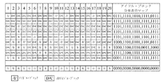
具体例が、以下で記載のために使用される。例えば、サービス多重化の後に取得されたデータ・ストリームが検出されてよい。図6において、400Gフレキシブル・イーサネット物理インターフェイス・グループにおける各物理インターフェイス上で送信される原データ・ストリームについて、最初のオーバーヘッド・ブロックの後の最初のコード・ブロックから開始して、連続したコード・ブロックが、図8に示されるアイドル・ブロック分布図を形成しながら、フレキシブル・イーサネット・データ・フレーム・フォーマットを参照してセグメント・データ・ストリームとして逐次選択される。上記の第1セグメント・データ・ストリームは、原データ・ストリームにおける連続した20個のコード・ブロックによって形成されたセグメント・データ・ストリームであってよい。フレキシブル・イーサネット・データ・フレーム・フォーマットは20個のタイムスロットに分割され得るので、20個のコード・ブロックを選択することは20個のタイムスロットに厳密に対応し得る。図8に示されるように、各行には20個のコード・ブロックがあり、20個のコード・ブロックは全てが非アイドル・ブロック“D/C”であってよく、あるいは、全てがアイドル・ブロック“/I/”であってもよく、あるいは、アイドル・ブロックと非アイドル・ブロックとの組み合わせであってもよい。図8は、いくつかのアイドル・ブロックの分布の例を示し、実際には、更なる分布ケースが存在し得る。
Specific examples are used below for description. For example, a data stream acquired after service multiplexing may be detected. In FIG. 6, consecutive code blocks, starting from the first code block after the first overhead block, for the original data stream sent on each physical interface in the 400G Flexible Ethernet Physical Interface Group . Are sequentially selected as a segment data stream with reference to the flexible Ethernet data frame format, forming the idle block distribution diagram shown in FIG. The first segment data stream may be a segment data stream formed by 20 consecutive code blocks in the original data stream. Since the flexible Ethernet data frame format can be divided into 20 time slots, selecting 20 code blocks can correspond exactly to 20 time slots. As shown in FIG. 8, there are 20 code blocks in each row, all 20 code blocks may be non-idle blocks “D/C”, or all idle blocks. It may be "/I/" or a combination of idle and non-idle blocks. FIG. 8 shows an example of the distribution of some idle blocks, and in practice additional distribution cases may exist.
図8において、アイドル・ブロック分布表示マップは、対応する20個のコード・ブロックにおけるアイドル・ブロック及び非アイドル・ブロックの位置分布を示すために、20ビットを使用してよい。アイドル・ブロック分布表示マップは、アイドル・ブロックの位置分布及び個数を示してよく、更には、非アイドル・ブロックの位置分布及び個数を示してよい。アイドル・ブロック分布表示マップは第1のビット及び第2のビットを含み、第1のビットはアイドル・ブロックを示し、第2のビットは非アイドル・ブロックを示す。例えば、図8において、ビット“0”はアイドル・ブロックを示し、ビット“1”は非アイドル・ブロックを示す。任意に、アイドル・ブロック分布表示マップにおいて、コード・ブロックは、2つ以上のビットを使用することによっても示されてよい。例えば、“00”はアイドル・ブロックを示し、“01”は非アイドル・ブロックを示す。 In FIG. 8, the idle block distribution display map may use 20 bits to indicate the position distribution of idle blocks and non-idle blocks in the corresponding 20 code blocks. The idle block distribution display map may indicate the position distribution and the number of idle blocks, and may further indicate the position distribution and the number of non-idle blocks. The idle block distribution display map includes a first bit and a second bit, the first bit indicating an idle block and the second bit indicating a non-idle block. For example, in FIG. 8, bit "0" indicates an idle block and bit "1" indicates a non-idle block. Optionally, in the idle block distribution map, code blocks may also be indicated by using more than one bit. For example, "00" indicates an idle block and "01" indicates a non-idle block.
図9に示されるように、原データ・ストリーム内の20個のコード・ブロックは、セグメント・データ・ストリームとして選択され、そして、セグメント・データ・ストリームのうちで、一部はアイドル・ブロックを含まず、一部は1つのアイドル・ブロックを含み、あるいは、一部は2つよりも多いアイドル・ブロックを含む。セグメント・データ・ストリームが少なくとも2つのアイドル・ブロックを含む場合に、アイドル・ブロック分布表示マップ及び/又はサービス分布表示マップは、マップ・ブロックを形成するよう、1つのアイドル・ブロック(第2アイドル・ブロック)の位置に挿入されてよい。BEサービスは、BEサービス・ブロックを形成するよう、残りのアイドル・ブロック(第1アイドル・ブロック)の位置に挿入される。1つしかアイドル・ブロックを含まないか、又はアイドル・ブロックを含まないセグメント・データ・ストリームについては、そのセグメント・データ・ストリームは、BEサービスを運ぶために使用され得ず、アイドル・ブロック分布表示マップ及び/又はサービス分布表示マップ、例えば、図9の使用されないアイドル・ブロック“/I/”、を運ぶためにも必要とされ得ない。サービス分布表示マップは、第1アイドル・ブロックの位置、すなわち、BEサービス・ブロックの位置を示してよい。アイドル・ブロック分布表示マップは、第1アイドル・ブロック及び第2アイドル・ブロックの位置を含め、アイドル・ブロックの位置を示してよい。サービス分布表示マップは、アイドル・ブロック分布表示マップから生成されてよい。サービス分布表示マップ及びアイドル・ブロック分布表示マップに含まれるビットの個数及びビットの値は、同じであってよい。サービス分布表示マップの生成は、BEサービスが挿入されるときに実行されてよく、あるいは、BEサービスが挿入された後に実行されてもよい。これは、本発明において限定されない。 As shown in FIG. 9, 20 code blocks in the original data stream are selected as the segment data stream, and some of the segment data streams include idle blocks. No, some contain one idle block, or some contain more than two idle blocks. If the segment data stream includes at least two idle blocks, the idle block distribution map and/or the service distribution map may include one idle block (second idle block) to form a map block. Block) position. The BE service is inserted at the position of the remaining idle block (first idle block) to form the BE service block. For a segment data stream that contains only one idle block or no idle block, the segment data stream cannot be used to carry BE services and the idle block distribution indicator It may also not be needed to carry the map and/or the service distribution map, eg the unused idle block “/I/” of FIG. The service distribution display map may indicate the position of the first idle block, that is, the position of the BE service block. The idle block distribution display map may show the positions of the idle blocks, including the positions of the first idle block and the second idle block. The service distribution display map may be generated from the idle block distribution display map. The number of bits and the value of the bits included in the service distribution display map and the idle block distribution display map may be the same. The generation of the service distribution display map may be performed when the BE service is inserted, or may be performed after the BE service is inserted. This is not a limitation of the present invention.
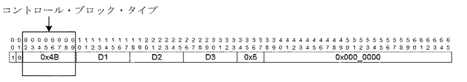
本発明のこの実施形態における“位置”は、相対位置である。2つのブロック(例えば、2つのアイドル・ブロック)間の相対位置は、不変なままであり得る。例えば、セグメント・データ・ストリームの最初の行において、第1アイドル・ブロック及び第2アイドル・ブロックは、8つの非アイドル・ブロックによって分離される。データ伝送プロセスの間、2つのアイドル・ブロック間の相対位置は不変なままであり得る。第2アイドル・ブロックの位置は、前もってセットされたマップ・ブロック・タイプを使用することによって特定される。図10aに示されるように、マップ・ブロック・タイプは、同期ヘッダ“10”、コントロール・ブロック・タイプ“4B”、及び“0xA”を含んでよい。3つのオクテットD1、D2及びD3、すなわち、全部で24ビットが使用され、それらから20ビットが、サービス分布表示マップ及び/又はアイドル・ブロック分布表示マップを運ぶためにランダムに選択されてよい。マップ・ブロック・タイプは、特定様式が先行技術における64B/66B符号化での15個のコントロール・ブロック・タイプと相違し、且つ、物理インターフェイスのコード・ブロック・タイプによって定義された制約要件を満足するという条件で、他の様式で特定されてよい点が留意されるべきである。例えば、図10bに示されるように、新しいコントロール・ブロック・タイプ“0x00”が本発明のこの実施形態では定義される。7つのオクテットD1乃至D6、すなわち、全部で56ビットが、サービス分布表示マップ及び/又はアイドル・ブロック分布表示マップを運ぶために使用されてよい。 "Position" in this embodiment of the invention is a relative position. The relative position between two blocks (eg, two idle blocks) may remain unchanged. For example, in the first row of the segment data stream, the first idle block and the second idle block are separated by eight non-idle blocks. During the data transfer process, the relative position between the two idle blocks may remain unchanged. The location of the second idle block is identified by using the preset map block type. As shown in Figure 10a, the map block type may include a sync header "10", a control block type "4B", and "0xA". Three octets D1, D2 and D3, a total of 24 bits are used, from which 20 bits may be randomly selected to carry the service distribution map and/or the idle block distribution map. The map block type differs from the 15 control block types in 64B/66B encoding in the prior art in a specific manner, and satisfies the constraint requirement defined by the physical interface code block type. It should be noted that it may be specified in other ways, provided that For example, as shown in Figure 10b, a new control block type "0x00" is defined in this embodiment of the invention. Seven octets D1 to D6, or a total of 56 bits, may be used to carry the service distribution map and/or the idle block distribution map.
原データ・ストリームにおいて第1アイドル・ブロック及び第2アイドル・ブロックを特定することは、原データ・ストリームから第2セグメント・データ・ストリームを取得し、第2セグメント・データ・ストリームにおいて、第1アイドル・ブロック及び第2アイドル・ブロックを含む少なくとも2つのアイドル・ブロックを特定することと、前もってセットされた関与情報を使用することによって第2セグメント・データ・ストリームの位置を特定することとを更に含んでよい。 Identifying a first idle block and a second idle block in the original data stream obtains a second segment data stream from the original data stream and a first idle block in the second segment data stream. Further comprising identifying at least two idle blocks including a block and a second idle block, and locating the second segment data stream by using preset engagement information Good.
任意に、いくつかのタイムスロットが、アイドル・ブロック(第1アイドル・ブロック及び第2アイドル・ブロックを含む。)の特定に関与しないタイムスロット(以下、簡潔に、“非関与タイムスロット”と呼ばれる。)として予め指定されてよい。図11に示されるように、タイムスロット3及びタイムスロット4は非関与タイムスロットと指定され、それら2つのタイムスロットに対応するコード・ブロックがアイドル・ブロックであるかどうかを特定することは不要となる。2つのタイムスロットに対応するコード・ブロックの2つの列に含まれるアイドル・ブロック“/I/”は、使用されないアイドル・ブロックである。すなわち、非関与タイムスロットに対応するアイドル・ブロックは、アイドル・ブロック分布表示マップ及び/又はサービス分布表示マップを運ばず、BEサービスも運ばない。
Optionally, some of the time slots are not involved in the identification of idle blocks (including the first idle block and the second idle block) (hereinafter simply referred to as "non-participating time slots"). .) may be designated in advance. As shown in FIG. 11,
例において、前もってセットされた関与情報は、サービス分布表示マップにおいて示されてよい。例えば、“00”は第1アイドル・ブロックを示し、“01”は非アイドル・ブロックを示し、“10”は、非関与タイムスロットに対応するアイドル・ブロックを示す。前もってセットされた関与情報は、代替的に、アイドル・ブロック分布表示マップにおいて運ばれてもよい。例えば、“00”は、第1アイドル・ブロック及び第2アイドル・ブロックを示し、“01”は非アイドル・ブロックを示し、“10”は、非関与タイムスロットに対応するアイドル・ブロックを示す。 In an example, the preset engagement information may be shown in the service distribution map. For example, "00" indicates the first idle block, "01" indicates the non-idle block, and "10" indicates the idle block corresponding to the non-participating time slot. The preset engagement information may alternatively be carried in the idle block distribution map. For example, "00" indicates the first idle block and the second idle block, "01" indicates the non-idle block, and "10" indicates the idle block corresponding to the non-participating time slot.
他の例において、前もってセットされた関与情報は、マスク動作の後に取得されたアイドル・ブロック分布表示マップを使用することによっても表されてよい。任意に、マスク動作は更に、同様の原理を使用することによってサービス分布表示マップに対して実行されてもよい。例えば、送信端デバイスは、アイドル・ブロック分布表示マップを運ぶために第2アイドル・ブロックの位置を使用し、受信端デバイスは、図12に示されるマスク・ビットを使用することによって、アイドル・ブロック分布表示マップに対してマスク動作を実行する。例えば、図12は、20ビットのマスク・ビット・シーケンスを示し、その中で第3及び第4ビットはいずれも“1”であり、非関与タイムスロットを示し、他のビットは全て“0”であり、関与タイムスロットを示す。“論理和”マスク動作が、20個のマスク・ビットと、20個のコード・ブロックを含むセグメント・データ・ストリームのアイドル・ブロック分布表示マップ(1が非アイドル・ブロックを特定し、0がアイドル・ブロックを特定する。)とを使用することによって、実行され、それにより、アイドル・ブロック分布表示マップの第3及び第4ビットは、第3及び第4ビットが0でないときに1にセットされ得る。具体的に言えば、BEサービスもサービス分布表示マップ又はアイドル・ブロック分布表示マップも、それら2つのビットに対応するコード・ブロックの位置に挿入され得ない。 In another example, the preset engagement information may also be represented by using the idle block distribution display map obtained after the mask operation. Optionally, masking operations may also be performed on the service distribution map by using similar principles. For example, the transmitting end device uses the position of the second idle block to carry the idle block distribution map and the receiving end device uses the mask bits shown in FIG. A mask operation is performed on the distribution display map. For example, FIG. 12 shows a 20-bit mask bit sequence in which the 3rd and 4th bits are both "1", indicating non-participating time slots, and all other bits being "0". And indicates the time slot involved. An "OR" mask operation is used to display an idle block distribution map of a segment data stream containing 20 mask bits and 20 code blocks (1 identifies non-idle blocks, 0 is idle). -Specify the block.) so that the 3rd and 4th bits of the idle block distribution map are set to 1 when the 3rd and 4th bits are non-zero. obtain. Specifically, neither the BE service nor the service distribution display map or the idle block distribution display map can be inserted at the positions of the code blocks corresponding to those two bits.
任意に、マスク・ビットは、前もってセットされた関与情報として、直接送信されてよい。表1に示されるように、非関与タイムスロットは、ビット“0”によって示されてよく、関与タイムスロットは、ビット“1”によって示される。代替的に、非関与タイムスロットは、ビット“1”によって示され、関与タイムスロットは、ビット“0”によって示される。

非関与タイムスロットの送信周波数は、異なる適用シナリオにおいて異なり得る。 The transmission frequency of the non-interesting time slots may be different in different application scenarios.
非関与タイムスロットが静的に構成される、すなわち、非関与タイムスロットが一定である場合には、前もってセットされた関与情報は実時間で送信される必要がなくてよい。前もってセットされた関与情報は、例えば、ネットワーク管理を通じて、送信端ネットワーク・デバイス及び受信端ネットワーク・デバイスにおいて直接構成されてよい。代替的に、前もってセットされた関与情報は、サービス伝送が開始する前に、フレキシブル・イーサネット・データ・フレームのオーバーヘッド・ブロックを使用することによって運ばれてもよい。 If the non-participating time slots are statically configured, i.e. the non-participating time slots are constant, then the pre-set engaging information need not be transmitted in real time. The preset engagement information may be configured directly at the sending and receiving network devices, eg, through network management. Alternatively, the preset engagement information may be carried by using the overhead block of the flexible Ethernet data frame before the service transmission starts.
非関与タイムスロットが動的に構成される、すなわち、非関与タイムスロットが実時間において変化する場合には、前もってセットされた関与情報は、実時間伝送のためにデータ・ストリームにおいて運ばれるべきである。前もってセットされた関与情報は、マップ・ブロックを使用することによって運ばれてよい。例えば、マスキングがサービス分布表示マップにおいて実行されてよく、あるいは、マスク・ビットが直接送信されてもよい。 If the non-participating timeslots are dynamically configured, i.e. the non-participating timeslots change in real time, then the preset engagement information should be carried in the data stream for real-time transmission. is there. The preset engagement information may be carried by using map blocks. For example, masking may be performed on the service distribution map, or mask bits may be sent directly.
非関与タイムスロットが準動的に構成される、すなわち、非関与タイムスロットがある期間内では一定である場合に、前もってセットされた関与情報は周期的に送信されてよい。例えば、フレキシブル・イーサネットにおける非関与タイムスロットのフレーム境界が変化し、タイムスロット3及び4がタイムスロット5及び6に変化する場合に、前もってセットされた関与情報は、フレキシブル・イーサネット・データ・フレームのオーバーヘッド・ブロックにおいて運ばれてよい。オーバーヘッド・ブロックは、1023×20個のコード・ブロックごとに現れることが図4から知られ得る。図13に示されるように、フレキシブル・イーサネット・データ・フレームの第2オーバーヘッド・ブロック及び/又は第3オーバーヘッド・ブロックの予備(Reserved)フィールドは、マスク・ビットのような、前もってセットされた関与情報を運ぶために使用されてよい。
The pre-set engagement information may be sent periodically if the non-interesting time slots are quasi-dynamically configured, i.e. the non-interesting time slots are constant over a period of time. For example, if the frame boundary of a non-participating timeslot in Flexible Ethernet changes and
前述の適用シナリオにおいて、前もってセットされた関与情報は、マスク・ビットであってよく、あるいは、マスク動作の後に取得されるアイドル・ブロック分布表示マップ又はサービス分布表示マップを使用することによって示されてもよい。例えば、図10aにおいては、D1、D2及びD3に加えて、28個の予備ビットが使用されてよい。アイドル・ブロック分布表示マップ又はサービス分布表示マップにおいて、非関与タイムスロットに対応するアイドル・ブロックは、“10”又はマスク動作を使用することによって示される。代替的に、マスク・ビットは、予備ビット又は同様のものを使用することによって運ばれる。 In the above application scenario, the preset engagement information may be mask bits, or may be indicated by using an idle block distribution map or service distribution map obtained after the mask operation. Good. For example, in FIG. 10a, 28 spare bits may be used in addition to D1, D2 and D3. In the idle block distribution map or service distribution map, idle blocks corresponding to non-interesting time slots are indicated by using "10" or mask operation. Alternatively, the mask bits are carried by using spare bits or the like.
任意に、アイドル・ブロックの特定に関与するタイムスロット(略して“関与タイムスロット”)は、予め指定されてよい。例えば、タイムスロット3及び4以外の他のタイムスロットが図11において指定される。実施原理は同様であり、詳細についてはここで再び記載されない。
Optionally, the time slots involved in identifying the idle block (abbreviated “participating time slots”) may be pre-specified. For example, time slots other than
任意に、非関与タイムスロットの一部又は全ては、専用のタイムスロットとしてBEサービスに割り当てられ、専用のタイムスロットは、BEサービスの基本的な、保証された帯域幅である。BEサービスの実際の帯域幅は、基本的な、保証された帯域幅を超えることがある。すなわち、BEサービスは、他のサービスのアイドル・タイムスロット・リソースを更に占有する可能性がある。第1アイドル・ブロックの位置及び/又は基本的な、保証された帯域幅に対応するコード・ブロック位置に挿入される場合に、BEサービスは、左から右の順序でセグメント・データ・ストリームに挿入されてよい。 Optionally, some or all of the non-participating time slots are allocated to the BE service as dedicated time slots, the dedicated time slots being the basic, guaranteed bandwidth of the BE service. The actual bandwidth of BE services may exceed the basic, guaranteed bandwidth. That is, the BE service may further occupy the idle timeslot resources of other services. The BE service is inserted in the segment data stream in left-to-right order when inserted at the code block position corresponding to the position of the first idle block and/or the basic guaranteed bandwidth. May be done.
第2アイドル・ブロック(又はマップ・ブロック)の位置は、第1セグメント・データ・ストリーム又は第2セグメント・データ・ストリームにおける第1の位置に調整される。受信端ネットワーク・デバイスがBEサービスを速く取得することを可能にするよう、BEサービスが挿入されているセグメント・データ・ストリームは、更に再配置されてよい。任意に、セグメント・データ・ストリームが最初に再配置されてよく、次いで、BEサービスがセグメント・データ・ストリームに挿入される。例において、図14に示されるように、第2アイドル・ブロック(又は、マップ・ブロック)は第1の位置に置かれ、次いで、非アイドル・ブロック及び第1アイドル・ブロック(又はBEサービス・ブロック)は引き続いて置かれる。代替的に、第1アイドル・ブロック(又はBEサービス・ブロック)が最初に置かれてよく、次いで、非アイドル・ブロックが置かれる。BEサービスを運ぶために使用されないセグメント・データ・ストリーム、例えば、第3及び第4の行におけるセグメント・データ・ストリームは、再配置されなくてもよい。他の例において、図15に示されるように、第1コード・ブロック及び第2アイドル・ブロックの位置は交換されてよく、それにより、第2アイドル・ブロック(又はマップ・ブロック)は、第1の位置で規則正しく現れる。任意に、第2アイドル・ブロック(又はマップ・ブロック)は、他の固定位置に置かれてもよい。 The position of the second idle block (or map block) is adjusted to the first position in the first segment data stream or the second segment data stream. The segment data stream in which the BE service is inserted may be further rearranged to allow the receiving end network device to obtain the BE service quickly. Optionally, the segment data stream may be relocated first, then the BE service is inserted into the segment data stream. In the example, as shown in FIG. 14, a second idle block (or map block) is placed in a first position, and then a non-idle block and a first idle block (or BE service block). ) Is placed subsequently. Alternatively, the first idle block (or BE service block) may be placed first, followed by the non-idle blocks. Segment data streams that are not used to carry BE services, eg, segment data streams in the third and fourth rows, may not be relocated. In another example, as shown in FIG. 15, the positions of the first code block and the second idle block may be swapped so that the second idle block (or map block) is Appears regularly at the position. Optionally, the second idle block (or map block) may be placed in another fixed location.
S14.BEサービス及びサービス分布表示マップを運ぶデータ・ストリームを送る。 S14. Send a data stream carrying the BE service and service distribution map.
本発明のこの実施形態において、任意に、S12で、フレキシブル・イーサネット・データ・フレームの最初のオーバーヘッド・ブロックの後の最初のコード・ブロックから開始して、40個の連続したコード・ブロックが、400Gフレキシブル・イーサネット物理インターフェイス・グループにおける各物理インターフェイス上でセグメント・データ・ストリームとして逐次選択されてよい。任意に、最初のオーバーヘッド・ブロックの後の最初のコード・ブロックから開始して、50個の連続したコード・ブロックが、100Gフレキシブル・イーサネット物理インターフェイス上でセグメント・データ・ストリームとして逐次選択されてよい。任意に、5個のコード・ブロック、10個のコード・ブロック、などがセグメント・データ・ストリームとして連続して選択されてよい。これは、本発明において限定されない。 In this embodiment of the invention, optionally, at S12, 40 consecutive code blocks, starting with the first code block after the first overhead block of the flexible Ethernet data frame, It may be sequentially selected as a segment data stream on each physical interface in the 400G Flexible Ethernet Physical Interface Group. Optionally, starting from the first code block after the first overhead block, 50 consecutive code blocks may be sequentially selected as the segment data stream on the 100G Flexible Ethernet physical interface. .. Optionally, 5 code blocks, 10 code blocks, etc. may be sequentially selected as the segment data stream. This is not a limitation of the present invention.
図10aを参照すると、D1、D2及びD3は、全部で24個のビットに加えて、28個の予備ビットを有し、全部で52個のビットが存在し、これらは、40ビットのサービス分布表示マップ及び/又はアイドル・ブロック分布表示マップを運ぶことができる。セグメント・データ・ストリームにおいて52よりも多いコード・ブロックがある場合に、少なくとも2つのコード・ブロックが、サービス分布表示マップ及び/又はアイドル・ブロック分布表示マップを運ぶために使用されてよい。図10bに示されるマップ・ブロックは、56ビットのサービス分布表示マップ及び/又はアイドル・ブロック分布表示マップを運んでよい。セグメント・データ・ストリームにおいて56よりも多いコード・ブロックがある場合に、少なくとも2つのコード・ブロックが、サービス分布表示マップ及び/又はアイドル・ブロック分布表示マップを運ぶために使用されてよい。任意に、同期ヘッダが“01”であるデータ・コード・ブロックが、サービス分布表示マップ及び/又はアイドル・ブロック分布表示マップを運ぶために使用されてよい。 Referring to FIG. 10a, D1, D2 and D3 have a total of 24 bits plus 28 reserved bits, and there are a total of 52 bits, which have a 40-bit service distribution. A display map and/or an idle block distribution display map may be carried. At least two code blocks may be used to carry the service distribution map and/or the idle block distribution map if there are more than 52 code blocks in the segment data stream. The map block shown in FIG. 10b may carry a 56-bit service distribution display map and/or an idle block distribution display map. If there are more than 56 code blocks in the segment data stream, at least two code blocks may be used to carry the service distribution indication map and/or the idle block distribution indication map. Optionally, a data code block with a sync header of "01" may be used to carry the service distribution map and/or the idle block distribution map.
少なくとも2つのコード・ブロックがサービス分布表示マップ及び/又はアイドル・ブロック分布表示マップを運ぶために使用される場合に、ポインタ・フィールドが、1つ以上のマップ・ブロックの位置を示すために使用されてよい。例えば、図16aにおいて、MapExフィールドが、少なくとも2つのマップ・ブロックのうちの第1マップ・ブロックに加えられ、第1マップ・ブロック以外の他のマップ・ブロックの位置を特定するために使用される。コントロール・ブロック・タイプ“4B”及び“0xA”を含むマップ・ブロック・タイプは、第1マップ・ブロックを特定するために使用される。MapExは、ポインタであり、他のマップ・ブロックの位置を示すために使用されてよい。代替的に、第2マップ・ブロックの位置は、第1マップ・ブロックのMapExを使用することによって示されてよく、第3マップ・ブロックの位置は、第2マップ・ブロックのMapExを使用することによって示され、以降同様である。任意に、他のマップ・ブロック・タイプ、例えば、コントロール・ブロック・タイプ“0x00”が、第1マップ・ブロックを特定するために使用されてよく、あるいは、セグメント長さ表示フィールドLインジケータが加えられ、セグメント・データ・ストリームの長さL、例えば80、を特定するために使用されてよい。任意に、全てのマップ・ブロックは、MapExポインタを使用せずにマップ・ブロック・タイプを使用することによって直接特定されてもよい。 A pointer field is used to indicate the location of one or more map blocks when at least two code blocks are used to carry the service distribution map and/or the idle block distribution map. You can For example, in FIG. 16a, the MapEx field is added to the first of the at least two map blocks and is used to locate other map blocks than the first map block. .. Map block types, including control block types "4B" and "0xA", are used to identify the first map block. MapEx is a pointer and may be used to indicate the location of other map blocks. Alternatively, the position of the second map block may be indicated by using the MapEx of the first map block, and the position of the third map block may be indicated by using the MapEx of the second map block. , And so on. Optionally, other map block types may be used to identify the first map block, for example the control block type "0x00" or a segment length indicator field L indicator may be added. , May be used to identify the length L of the segment data stream, eg 80. Optionally, all map blocks may be directly specified by using the map block type without using the MapEx pointer.
セグメント・データ・ストリームの長さがLである場合に、フレキシブル・イーサネット・データ・フレームの境界位置に対して、セグメント・データ・ストリームの境界位置は不確かであり得る。例えば、Lが50である場合に、20×1023個のコード・ブロックの長さを有するサブフレーム、20×1023×8個のコード・ブロックの長さを有する基本フレーム、及び20×1023×8×32個のコード・ブロックの長さを有するスーパーフレームに対して、セグメント・データ・ストリームの境界は、境界位置アライメント問題を有している。すなわち、フレキシブル・イーサネット・データ・フレームにおける第1セグメント・データ・ストリーム内の第1コード・ブロックの位置は、L≧pi≧1であるとして、フレキシブル・イーサネット・データ・フレームの(pi)番目のコード・ブロックにあり得る。従って、セグメント境界ポインタpiは、フレキシブル・イーサネットのオーバーヘッドに加えられる必要があり得る。例えば、6ビットの境界ポインタ・フィールド(0から63)が、現在のフレームにおける第1セグメント・データ・ストリームの開始位置を示すよう、フレキシブル・イーサネット・データ・フレームのオーバーヘッドにおいて定義される。
If the length of the segment data stream is L, the boundary position of the segment data stream may be uncertain with respect to the boundary position of the flexible Ethernet data frame. For example, when L is 50, a subframe having a length of 20×1023 code blocks, a base frame having a length of 20×1023×8 code blocks, and 20×1023×8. For superframes having a length of x32 code blocks, the boundaries of the segment data stream have boundary position alignment problems. That is, it is assumed that the position of the first code block in the first segment data stream in the flexible Ethernet data frame is L≧pi≧1 and the (pi)th position of the flexible Ethernet data frame is It can be in a code block. Therefore, the segment boundary pointer pi may need to be added to the Flexible Ethernet overhead. For example, a 6-bit boundary pointer field (0 to 63) is defined in the Flexible Ethernet data frame overhead to indicate the starting position of the first segment data stream in the current frame.
任意に、フレキシブル・イーサネットにおいて、複数の物理インターフェイスは、物理インターフェイス・グループを形成するようカスケード接続され、セグメント・データ・ストリームは、複数の物理インターフェイス上で並列に取得されてよい。例えば、n個の物理インターフェイスをカスケード接続することによって形成されたフレキシブル・イーサネット物理インターフェイス・グループにおいて、k個のコード・ブロックが各物理インターフェイス上で選択され、セグメント・データ・ストリームの長さはL=n×kである。例えば、4つの100G物理インターフェイスがあり、20個のコード・ブロックが各インターフェイス上で選択される場合に、n=4、k=20、且つn×k=80である。n×kのより大きい値は、2つよりも多いアイドル・ブロックの存在のより高い可能性、すなわち、BEサービスが挿入され得るより高い可能性、を示す点が留意されるべきである。セグメント・データ・ストリームは、複数の物理インターフェイス上で並列に取得され、これは、帯域幅利用効率を改善し且つ処理遅延を低減するのを助ける。セグメント・データ・ストリームのセグメント境界は、フレキシブル・イーサネット・データ・フレームの境界、すなわち、フレキシブル・イーサネット・データ・フレームの最初のオーバーヘッド・ブロック、を参照して決定されてよい。 Optionally, in Flexible Ethernet, multiple physical interfaces may be cascaded to form a physical interface group and segment data streams may be acquired in parallel on the multiple physical interfaces. For example, in a flexible Ethernet physical interface group formed by cascading n physical interfaces, k code blocks are selected on each physical interface and the length of the segment data stream is L. =nxk. For example, if there are four 100G physical interfaces and 20 code blocks are selected on each interface, then n=4, k=20, and n×k=80. It should be noted that larger values of nxk indicate a higher probability of the presence of more than two idle blocks, i.e. a higher probability that BE services can be inserted. The segment data streams are acquired in parallel on multiple physical interfaces, which helps improve bandwidth utilization efficiency and reduce processing delays. The segment boundaries of the segment data stream may be determined with reference to the flexible Ethernet data frame boundaries, ie, the first overhead block of the flexible Ethernet data frame.
本発明のこの実施形態において、ネットワーク・デバイスは、少なくとも2つのデータ・ストリームを取得し、少なくとも2つのデータ・ストリームは第1データ・ストリーム及び第2データ・ストリームを含み、第1データ・ストリームは、第3データ・ストリームを生成するよう、第2データ・ストリームに挿入され、第3データ・ストリームは第1情報ブロック及び第2情報ブロックを含み、第1情報ブロック及び第2情報ブロックは第2データ・ストリームから生成され、第1情報ブロックは、第1データ・ストリームを運ぶために使用され、第2データ・ストリームは、第1データ・ストリーム分布表示マップを運ぶために使用され、第1データ・ストリーム分布表示マップは、第1情報ブロックの位置を示すために使用され、第2情報ブロックは、前もってセットされたマップ・ブロック・タイプを使用することによって特定され、第3データ・ストリームは送られる。本発明のこの実施形態における技術的解決法は、図7に示される方法プロシージャを使用することによって実施されてよい。例えば、第1データ・ストリームは、BEサービスによって形成されたデータ・ストリームであってよく、第2データ・ストリームは、専用の帯域幅を有するサービスによって形成された原データ・ストリームであってよい。第1情報ブロックはBEサービス・ブロックであってよく、第2情報ブロックはマップ・ブロックであってよい。第1データ・ストリーム分布表示マップは、アイドル・ブロック分布表示マップ及び/又はサービス分布表示マップであってよい。しかし、本発明のこの実施形態の実施は、図7に示される方法プロシージャに限られない。例えば、S12で、アイドル・ブロックは特定される必要がなくてもよいが、アイドル・ブロックが生成される必要がある位置は、専用の帯域幅を有するサービスが原データ・ストリームを形成するプロセスの間に決定され、BEサービス及びサービス分布表示マップは、アイドル・ブロックが生成される必要がある位置に挿入される。 In this embodiment of the invention, the network device obtains at least two data streams, the at least two data streams including a first data stream and a second data stream, the first data stream being , A third data stream is inserted into the second data stream to generate a third data stream, the third data stream including a first information block and a second information block, and the first information block and the second information block being a second information block. Generated from the data stream, the first information block is used to carry the first data stream, the second data stream is used to carry the first data stream distribution map, and the first data block is used. The stream distribution map is used to indicate the location of the first information block, the second information block is identified by using a preset map block type, and the third data stream is sent. To be The technical solution in this embodiment of the invention may be implemented by using the method procedure shown in FIG. For example, the first data stream may be a data stream formed by a BE service and the second data stream may be an original data stream formed by a service having a dedicated bandwidth. The first information block may be a BE service block and the second information block may be a map block. The first data stream distribution display map may be an idle block distribution display map and/or a service distribution display map. However, the implementation of this embodiment of the invention is not limited to the method procedure shown in FIG. For example, at S12, idle blocks may not need to be identified, but the location at which idle blocks need to be generated is in the process where a service with dedicated bandwidth forms the original data stream. Determined in between, the BE service and service distribution display map is inserted at the location where the idle block needs to be generated.
本発明のこの実施形態において、BEサービスは、専用の帯域幅を有するサービスのアイドル・ブロック又は冗長情報ブロックを使用することによって運ばれ、それにより、専用の帯域幅を有するサービスのアイドル・タイムスロットは十分に利用され、それによって、帯域幅利用を改善し、且つ、フレキシブル・イーサネットにおいてサービスの統計多重化を実装する。 In this embodiment of the invention, the BE service is carried by using idle blocks or redundant information blocks of the service with dedicated bandwidth, whereby idle time slots of the service with dedicated bandwidth are provided. Is fully utilized, thereby improving bandwidth utilization and implementing statistical multiplexing of services in Flexible Ethernet.
図17は、本発明の実施形態に従うサービス受信方法のフローチャートの例である。方法は、フレキシブル・イーサネット・デバイス又はイーサネット・デバイスのようなネットワーク・デバイスによって実行されてよく、ネットワーク・デバイスは、受信端ネットワーク・デバイスであってよい。本発明のこの実施形態において、受信端ネットワーク・デバイスによって実行される方法は、サービス逆多重化プロセスの間に実行されてよく、あるいは、サービス逆多重化の前又は後に実行されてもよい。サービス逆多重化プロセス及び図6に示される多重化プロセスは相互に逆であり、詳細についてはここで再び記載されない。確かに、本発明のこの実施形態における解決法は、サービス逆多重化プロセスとの関連を有さなくてもよい。サービス逆多重化プロセス及び本発明のこの実施形態は、以下で記載のために組み合わされ、これは、単に、記載のための例として使用される。方法は次のステップを含む。 FIG. 17 is an example of a flowchart of a service receiving method according to an embodiment of the present invention. The method may be performed by a network device such as a flexible Ethernet device or an Ethernet device, which may be a receiving end network device. In this embodiment of the invention, the method performed by the receiving end network device may be performed during the service demultiplexing process, or may be performed before or after the service demultiplexing. The service demultiplexing process and the multiplexing process shown in FIG. 6 are reciprocal of each other and details will not be described here again. Indeed, the solution in this embodiment of the invention may have no relevance to the service demultiplexing process. The service demultiplexing process and this embodiment of the invention are combined below for description, which is used merely as an example for description. The method includes the following steps.
S21.ネットワーク・デバイスは、BEサービス及びサービス分布表示マップを運ぶデータ・ストリームを受信する。 S21. The network device receives a data stream carrying a BE service and a service distribution display map.
BEサービス及びサービス分布表示マップを運ぶデータ・ストリームは、専用の帯域幅を有するサービスを更に運んでよい。BEサービスは、専用の帯域幅を有するサービスのアイドル・タイムスロットを使用することによって運ばれてよい。専用の帯域幅を有するサービスのアイドル・タイムスロットを使用することによってBEサービスを運ぶ方法については、図7に示される実施形態を参照されたい。 The data stream carrying the BE service and the service distribution map may further carry a service with dedicated bandwidth. BE services may be carried by using idle timeslots of services that have dedicated bandwidth. Please refer to the embodiment shown in FIG. 7 for a method of carrying BE services by using idle timeslots of services with dedicated bandwidth.
S22.第2情報ブロックからサービス分布表示マップを取得し、サービス分布表示マップは、第1情報ブロックの位置を示すために使用され、第2情報ブロックは、前もってセットされたマップ・ブロック・タイプを使用することによって特定される。 S22. Obtaining the service distribution display map from the second information block, the service distribution display map is used to indicate the position of the first information block, and the second information block uses the preset map block type. Specified by
例において、このステップは、サービス逆多重化プロセスの間に実行されてよい。すなわち、本発明の技術的解決法は、受信されたデータ・ストリームが逆多重化されるときに同時に実行される。 In an example, this step may be performed during the service demultiplexing process. That is, the technical solution of the present invention is performed simultaneously when the received data stream is demultiplexed.
他の例において、このステップは、サービス逆多重化の前に実行されてもよい。すなわち、BEサービスが最初に、受信されたデータ・ストリームから抽出され、次いで、専用の帯域幅を有するサービスが逆多重化される。 In another example, this step may be performed before service demultiplexing. That is, BE services are first extracted from the received data stream, and then services with dedicated bandwidth are demultiplexed.
第1情報ブロックは、BEサービスを運ぶBEサービス・ブロックであってよく、第2情報ブロックは、サービス分布表示マップを運ぶマップ・ブロックであってよい。第2情報ブロックからサービス分布表示マップを取得することの実施は、BEサービス及びサービス分布表示マップを運ぶデータ・ストリームから第1セグメント・データ・ストリームを取得し、第1セグメント・データ・ストリームにおいてマップ・ブロック・タイプを特定し、マップ・ブロック・タイプによって特定された第2情報ブロックからサービス分布表示マップを取得することを含んでよい。 The first information block may be a BE service block carrying a BE service and the second information block may be a map block carrying a service distribution display map. Implementation of obtaining the service distribution indication map from the second information block includes obtaining a first segment data stream from a data stream carrying a BE service and a service distribution indication map, and a map in the first segment data stream. Identifying a block type and obtaining a service distribution display map from the second information block identified by the map block type.
第1セグメント・データ・ストリームの長さは、送信端ネットワーク・デバイスによって選択されたものと同じであってよく、あるいは、それと異なってもよい点が留意されるべきである。マップ・ブロック・タイプ及び、マップ・ブロックからサービス分布表示マップを取得する方法については、図10a及び図10bに示される実施形態を参照されたく、詳細についてはここで再び記載されない。
It should be noted that the length of the first segment data stream may be the same as or different from that selected by the sending end network device. Map block type and information about how to obtain the service distribution display map map blocks, reference is made to the detailed embodiment shown in Figures 10a and 10 b, it is not described again here for details.
任意に、ネットワーク・デバイスは、前もってセットされた関与情報を更に取得し、前もってセットされた関与情報に基づき、BEサービス及びサービス分布表示マップを運ぶデータ・ストリームから第2セグメント・データ・ストリームを取得してよい。前もってセットされた関与情報は、第2セグメント・データ・ストリームの位置を示す。送信端ネットワーク・デバイスが、第1セグメント・データ・ストリームにおいて、アイドル・ブロックの特定に関与しないいくつかのタイムスロットを指定する場合に、受信端ネットワーク・デバイスは、送信端ネットワーク・デバイスの指定されたルールに従って、前もってセットされた関与情報を取得し、前もってセットされた関与情報に基づき第2セグメント・データ・ストリーム(関与タイムスロット)からサービス分布表示マップ及びBEサービスを取得する必要がある。送信端ネットワーク・デバイスが非関与タイムスロットを指定するルールについては、図11、図12及び図13に示される実施形態を参照されたく、詳細についてはここで再び記載されない。 Optionally, the network device further obtains the preset engagement information and, based on the preset engagement information, obtains the second segment data stream from the data stream carrying the BE service and the service distribution map. You can do it. The preset engagement information indicates the position of the second segment data stream. The receiving end network device is designated as the sending end network device if the sending end network device specifies some time slots in the first segment data stream that are not involved in the identification of idle blocks. According to the rules described above, it is necessary to obtain the preset engagement information, and obtain the service distribution display map and the BE service from the second segment data stream (involvement time slot) based on the preset engagement information. For the rules by which the sending end network device specifies the non-participating time slots, refer to the embodiments shown in FIGS. 11, 12 and 13, and details are not described here again.
第2情報ブロックからサービス分布表示マップを取得することは、第1セグメント・データ・ストリーム又は第2セグメント・データ・ストリームにおける第1の位置からサービス分布表示マップを取得することを含む。送信端ネットワーク・デバイスがセグメント・データ・ストリームを再配置する場合に(図14及び図15に示される実施形態を参照されたい。)、受信端ネットワーク・デバイスは、送信端の再配置ルールに従って、第1セグメント・データ・ストリーム又は第2セグメント・データ・ストリームにおける前もってセットされた第1の位置からサービス分布表示マップを取得してよい。 Obtaining the service distribution display map from the second information block includes obtaining the service distribution display map from a first position in the first segment data stream or the second segment data stream. When the sending end network device relocates the segment data stream (see the embodiments shown in FIGS. 14 and 15), the receiving end network device follows the sending end relocation rule. The service distribution display map may be obtained from a preset first position in the first segment data stream or the second segment data stream.
サービス分布表示マップは、第1のビットを使用することによって第1情報ブロックの位置を特定してよい。例えば、図9に示されるように、BEサービスが挿入されている第1情報ブロックの位置は、ビット“0”を使用することによって特定される。 The service distribution indicator map may locate the first information block by using the first bit. For example, as shown in FIG. 9, the position of the first information block in which the BE service is inserted is specified by using the bit “0”.
S23.サービス分布表示マップに基づき第1情報ブロックからBEサービスを取得する。 S23. The BE service is acquired from the first information block based on the service distribution display map.
サービス分布表示マップは、例えば、ビット“0”を使用することによって、BEサービスの位置を示すことができる。サービス分布表示マップが、同じビット(例えば、“0”)を使用することによって、第1情報ブロックの位置及び第2情報ブロックの位置を示す場合に、第2情報ブロックは最初に、マップ・ブロック・タイプに基づき特定され、サービス分布表示マップは第2情報ブロックから取得され、第2情報ブロックの位置は、第1情報ブロックの位置を取得するよう、サービス分布表示マップから除かれる。 The service distribution map can indicate the location of BE services, for example by using bit "0". If the service distribution indicator map indicates the location of the first information block and the location of the second information block by using the same bit (eg, "0"), the second information block is first the map block. -Specified based on type, the service distribution display map is obtained from the second information block, and the position of the second information block is excluded from the service distribution display map to obtain the position of the first information block.
S24.BEサービス及びサービス分布表示マップを運ぶデータ・ストリームを原データ・ストリームへリストアする。 S24. Restore the data stream carrying the BE service and service distribution map to the original data stream.
本発明のこの実施形態において、少なくとも2つのアイドル・ブロックは、第1情報ブロック及び第2情報ブロックの位置で生成され、アイドル・ブロックは、アイドル・ブロック・タイプを運ぶ。サービス分布表示マップが第2情報ブロックから抽出され、BEサービスが第1情報ブロックから抽出されることになった後、アイドル・ブロックは、第2情報ブロック及び第1情報ブロックの位置で別々に生成されてよい。BEサービスは、専用の帯域幅を有するサービスのアイドル・タイムスロット(アイドル・ブロックの位置)を使用することによって伝送されるので、BEサービス・ブロック及びマップ・ブロックは、原アイドル・ブロックにリストアされる。すなわち、専用の帯域幅を有するサービスのみを運ぶ原データ・ストリームがリストアされる。アイドル・ブロックのフィールド・フォーマットについては、図5bに示される実施形態を参照されたい。 In this embodiment of the invention, at least two idle blocks are generated at the locations of the first information block and the second information block, the idle blocks carrying idle block types. After the service distribution display map is extracted from the second information block and the BE service is to be extracted from the first information block, idle blocks are generated separately at the positions of the second information block and the first information block. May be done. BE services are transmitted by using idle timeslots (locations of idle blocks) of services that have dedicated bandwidth, so that BE service blocks and map blocks are restored to the original idle blocks. It That is, the original data stream that carries only services with dedicated bandwidth is restored. For the field format of the idle block, please refer to the embodiment shown in FIG. 5b.
本発明のこの実施形態において、ネットワーク・デバイスは第3データ・ストリームを受信し、第3データ・ストリームから第1データ・ストリームを抽出し、第3データ・ストリームを第2データ・ストリームへリストアする。第3データ・ストリームは第1情報ブロック及び第2情報ブロックを含み、第2データ・ストリームは、第1情報ブロック及び第2情報ブロックを使用することによってリストアされる。第1情報ブロックは、第1データ・ストリームを運ぶために使用され、第2情報ブロックは、第1データ・ストリーム分布表示マップを運ぶために使用される。第1データ・ストリーム分布表示マップは、第1情報ブロックの位置を示すために使用され、第2情報ブロックは、前もってセットされたマップ・ブロック・タイプを使用することによって特定される。本発明のこの実施形態における技術的解決法は、図17に示される方法プロシージャを使用することによって実施されてよい。例えば、第3データ・ストリームは、BEサービス及びサービス分布表示マップを運ぶデータ・ストリームであってよく、第1データ・ストリームは、BEサービスによって形成されたデータ・ストリームであってよく、第2データ・ストリームは、専用の帯域幅を有するサービスによって形成された原データ・ストリームであってよい。第1情報ブロックはBEサービス・ブロックであってよく、第2情報ブロックはマップ・ブロックであってよく、第1データ・ストリーム分布表示マップは、サービス分布表示マップであってよい。しかし、本発明のこの実施形態の実施は、図17に示される方法プロシージャに限られない。例えば、S21で、BEサービス及びサービス分布表示マップは、異なるデータ・ストリームから受信されてもよい。 In this embodiment of the invention, the network device receives a third data stream, extracts a first data stream from the third data stream, and restores the third data stream to a second data stream. .. The third data stream includes a first information block and a second information block, and the second data stream is restored by using the first information block and the second information block. The first information block is used to carry the first data stream and the second information block is used to carry the first data stream distribution indicator map. The first data stream distribution map is used to indicate the location of the first information block and the second information block is identified by using the preset map block type. The technical solution in this embodiment of the invention may be implemented by using the method procedure shown in FIG. For example, the third data stream may be a data stream carrying a BE service and a service distribution map and the first data stream may be a data stream formed by the BE service and the second data stream. The stream may be an original data stream formed by a service with dedicated bandwidth. The first information block may be a BE service block, the second information block may be a map block, and the first data stream distribution display map may be a service distribution display map. However, the implementation of this embodiment of the invention is not limited to the method procedure shown in FIG. For example, at S21, BE services and service distribution display maps may be received from different data streams.
本発明のこの実施形態において、BEサービスは、専用の帯域幅を有するサービスのアイドル・ブロック又は冗長情報ブロックを使用することによって運ばれ、そして、BEサービスは、専用の帯域幅を有するサービスから抽出され、それにより、専用の帯域幅を有するサービスのアイドル・タイムスロットは十分に利用され、それによって、帯域幅利用を改善し、且つ、フレキシブル・イーサネットにおいてサービスの統計多重化を実装する。 In this embodiment of the invention, the BE service is carried by using idle blocks or redundant information blocks of the service with dedicated bandwidth, and the BE service is extracted from the service with dedicated bandwidth. The idle time slots of a service with dedicated bandwidth are thereby fully utilized, thereby improving bandwidth utilization and implementing statistical multiplexing of services in Flexible Ethernet.
フレキシブル・イーサネットに適用されることに加えて、本発明のこの実施形態で提供される技術的解決法は、他のタイプのネットワーク、例えば、イーサネット、OTN、又はSDHに適用されてもよい。現在、フレキシブル・イーサネットにおいては、データ・ストリームは64B/66B符号化を通じて符号化される。実際に、符号化されていないデータ・ストリーム又は復号されたデータ・ストリームにおけるオクテット・バイト・グループは、64B/66Bコード・ブロックに対応してよい。例えば、イーサネットのMII(Media Independent Interface,メディア独立インターフェイス)インターフェイスにおいて、MIIインターフェイス・データは、符号化されていない又は復号された文字であってよい。異なるインターフェイス・レートに応じて、MIIインターフェイスは、1Gbps媒体独立インターフェイス(1000Mbps Media Independent Interface,GMII)、10Gbps媒体独立インターフェイス(10Gbps Media Independent Interface,XGMII)、40Gbps媒体独立インターフェイス(40Gbps Media Independent Interface,XLGMII)、100Gbps媒体独立インターフェイス(100Gbps Media Independent Interface,CGMII)、400Gbps媒体独立インターフェイス(400Gbps Media Independent Interface,CDGMII)、などであってよい。表2に示されるように、最初の2つの列は、伝送(文字)制御(信号)(Transmit (character) Control (signals),TXC)/受信(文字)制御(信号)(Received (character) Control (signals),RXC)、及び伝送(文字)データ(Transmit (character) Data,TXD)/受信(文字)データ(Received (character) Data,RXD)を含むMIIインターフェイス・データ文字である。<TXC,TXD>又は<RXC,RXD>の各対は、64B/66B符号化のブロック・タイプに対応してよい。例えば、TXC/RXCが“0b1”であり、TXD/RXDが“0x07”であるとき、対応するブロックはアイドル・ブロックである。64B/66B符号化の間、TXD/RXDの“0x07”は7ビット“0x00”に圧縮される。
複数の予備文字(灰色領域)が表2には存在し、如何なる予備文字も、サービス分布表示マップ及び/又はアイドル・ブロック分布表示マップを運ぶために選択されてよい。例えば、図3に示されるように、MIIインターフェイス文字<TXC,TXD>又は<RXC,RXD>は、64B/66B符号化フォーマットにおけるマップ・ブロックとのマッピング関係を確立するよう、<0b1,0xFF>にセットされてよい。従って、本発明のこの実施形態における技術的解決法は、MIIインターフェイス・データ文字のような、符号化されていない文字に基づき更に実施されてよい。確かに、本発明のこの実施形態は、8B/10B符号化及び512B/514B符号化のような他の符号化フォーマットと適合してもよい。
図18は、本発明の実施形態に従うサービス送信装置の略構造図である。装置は、フレキシブル・イーサネット・デバイス、イーサネット・デバイス、OTNデバイス、SDHデバイス、などであってよい。図18に示されるように、装置は、取得モジュール101、処理モジュール102、及び送信モジュール103を含んでよい。本発明のこの実施形態において、機能モジュールは論理的に分けられているが、分割様式は限定されない。例えば、各モジュールは、独立した回路モジュールであってよく、あるいは、回路モジュールに一体化されてもよい。各モジュールは、チップのような集積回路の形で実施されてもよい。本発明のこの実施形態におけるサービス送信装置は、図7に示される実施形態における方法ステップを実行してよい。
FIG. 18 is a schematic structural diagram of a service transmitting apparatus according to an embodiment of the present invention. The device may be a flexible Ethernet device, an Ethernet device, an OTN device, an SDH device, etc. As shown in FIG. 18, the device may include an
取得モジュール101は、少なくとも2つのデータ・ストリームを取得するよう構成され、少なくとも2つのデータ・ストリームは、第1データ・ストリーム及び第2データ・ストリームを含む。
The
処理モジュール102は、第3データ・ストリームを生成するよう、第1データ・ストリームを第2データ・ストリームに挿入するよう構成される。
The
第3データ・ストリームは、第1情報ブロック及び第2情報ブロックを含み、第1情報ブロック及び第2情報ブロックは、第2データ・ストリームから生成される。 The third data stream includes a first information block and a second information block, and the first information block and the second information block are generated from the second data stream.
第1情報ブロックは、第1データ・ストリームを運ぶために使用され、第2情報ブロックは、第1データ・ストリーム分布表示マップを運ぶために使用され、第1データ・ストリーム分布表示マップは、第1情報ブロックの位置を示すために使用され、第2情報ブロックは、前もってセットされたマップ・ブロック・タイプを使用することによって特定される。 The first information block is used to carry a first data stream, the second information block is used to carry a first data stream distribution display map, and the first data stream distribution display map is Used to indicate the position of one information block, the second information block is identified by using a preset map block type.
送信モジュール103は、第3データ・ストリームを送信するよう構成される。
The sending
本発明のこの実施形態において、BEサービスは、専用の帯域幅を有するサービスのアイドル・ブロック又は冗長情報ブロックを使用することによって運ばれ、それにより、専用の帯域幅を有するサービスのアイドル・タイムスロットは十分に利用され、それによって、帯域幅利用を改善し、フレキシブル・イーサネットにおいてサービスの統計多重化を実装する。 In this embodiment of the invention, the BE service is carried by using idle blocks or redundant information blocks of the service with dedicated bandwidth, whereby idle time slots of the service with dedicated bandwidth are provided. Is fully utilized, thereby improving bandwidth utilization and implementing statistical multiplexing of services in Flexible Ethernet.
図19は、本発明の実施形態に従うサービス受信装置の略構造図である。装置は、フレキシブル・イーサネット・デバイス、イーサネット・デバイス、OTNデバイス、SDHデバイス、などであってよい。図19に示されるように、装置は、受信モジュール201及び処理モジュール202を含んでよい。本発明のこの実施形態において、機能モジュールは論理的に分けられているが、分割様式は限定されない。例えば、各モジュールは、独立した回路モジュールであってよく、あるいは、回路モジュールに一体化されてもよい。各モジュールは、チップのような集積回路の形で実施されてもよい。本発明のこの実施形態におけるサービス受信装置は、図17に示される実施形態における方法ステップを実行してよい。
FIG. 19 is a schematic structural diagram of a service receiving apparatus according to an embodiment of the present invention. The device may be a flexible Ethernet device, an Ethernet device, an OTN device, an SDH device, etc. As shown in FIG. 19, the device may include a
受信モジュール201は、第3データ・ストリームを受信するよう構成される。
The receiving
処理モジュール202は、第3データ・ストリームから第1データ・ストリームを抽出し、第3データ・ストリームを第2データ・ストリームへリストアするよう構成される。
The
第3データ・ストリームは、第1情報ブロック及び第2情報ブロックを含み、第2データ・ストリームは、第1情報ブロック及び第2情報ブロックを使用することによってリストアされる。 The third data stream includes a first information block and a second information block, and the second data stream is restored by using the first information block and the second information block.
第1情報ブロックは、第1情報ブロックを運ぶために使用され、第2情報ブロックは、第1データ・ストリーム分布表示マップを運ぶために使用され、第1データ・ストリーム分布表示マップは、第1情報ブロックの位置を示すために使用され、第2情報ブロックは、前もってセットされたマップ・ブロック・タイプを使用することによって特定される。 The first information block is used to carry the first information block, the second information block is used to carry the first data stream distribution display map, and the first data stream distribution display map is the first data stream distribution display map. Used to indicate the location of the information block, the second information block is identified by using the preset map block type.
本発明のこの実施形態において、BEサービスは、専用の帯域幅を有するサービスのアイドル・ブロック又は冗長情報ブロックを使用することによって運ばれ、そして、BEサービスは、専用の帯域幅を有するサービスから抽出され、それにより、専用の帯域幅を有するサービスのアイドル・タイムスロットは十分に利用され、それによって、帯域幅利用を改善し、フレキシブル・イーサネットにおいてサービスの統計多重化を実装する。 In this embodiment of the invention, the BE service is carried by using idle blocks or redundant information blocks of the service with dedicated bandwidth, and the BE service is extracted from the service with dedicated bandwidth. The idle time slots of a service with dedicated bandwidth are then fully utilized, thereby improving bandwidth utilization and implementing statistical multiplexing of services in Flexible Ethernet.
図20は、本発明の実施形態に従うネットワーク・システムの略構造図である。ネットワーク・システムは、フレキシブル・イーサネット、イーサネット、OTN、SDHネットワーク、などであってよい。図20に示されるように、ネットワーク・システムは、少なくとも2つのネットワーク・デバイス、例えば、ネットワーク・デバイス301及びネットワーク・デバイス302を含んでよい。各ネットワーク・デバイスは、送信端ネットワーク・デバイス又は受信端ネットワーク・デバイスであってよく、図18及び/又は図19に示される構造を有してよい。
FIG. 20 is a schematic structural diagram of a network system according to an embodiment of the present invention. The network system may be Flexible Ethernet, Ethernet, OTN, SDH network, and so on. As shown in FIG. 20, the network system may include at least two network devices, eg,
図21は、本発明の実施形態に従うネットワーク・デバイスの略構造図である。ネットワーク・デバイスは、フレキシブル・イーサネット・デバイス、イーサネット・デバイス、OTNデバイス、SDHデバイス、などであってよい。図21に示されるように、ネットワーク・デバイス400は、プロセッサ401、メモリ402、少なくとも1つのネットワーク・インターフェイス403(例えば、ネットワーク・インターフェイス403及びネットワーク・インターフェイス404)、逆多重化チップ405、及び多重化チップ406を含んでよい。ネットワーク・デバイスが送信機能及び受信機能を含む場合に、逆多重化チップ405及び多重化チップ406が含まれてよく、あるいは、ネットワーク・デバイスが送信機能しか含まない場合には、多重化チップ406しか含まれなくてよく、あるいは、ネットワーク・デバイスが受信機能しか含まない場合には、逆多重化チップ405しか含まれなくてよい。
FIG. 21 is a schematic structural diagram of a network device according to an embodiment of the present invention. The network device may be a flexible Ethernet device, an Ethernet device, an OTN device, an SDH device, etc. As shown in FIG. 21, network device 400 includes processor 401,
プロセッサ401は、関連するプログラムを実行して、本発明の実施形態で提供される技術的解決法を実施するよう構成された汎用の中央演算処理装置(Central Processing Unit,CPU)、マイクロプロセッサ、ネットワーク・プロセッシング・ユニット(Network Processing Unit,NPU)、特定用途向け集積回路(Application-Specific Integrated Circuit,ASIC)、又は少なくとも1つの集積回路であってよい。 The processor 401 is a general-purpose central processing unit (CPU), microprocessor, network configured to execute related programs to implement the technical solutions provided in the embodiments of the present invention. It may be a processing unit (Network Processing Unit, NPU), an application-specific integrated circuit (ASIC), or at least one integrated circuit.
メモリ402は、リード・オンリー・メモリ(Read-Only Memory,ROM)、静的記憶デバイス、動的記憶デバイス、又はランダム・アクセス・メモリ(Random Access Memory,RAM)であってよい。メモリ402は、オペレーティング・システム及び他のアプリケーション・プログラムを記憶してよい。本発明の実施形態で提供される技術的解決法が、ソフトウェア又はファームウェアを使用することによって実施される場合に、本発明の実施形態で提供される技術的解決法を実施するためのプログラム・コードがメモリ402に記憶され、プロセッサ401によって実行される。
The
ネットワーク・インターフェイス403及び404は、例えば、制限なしに、ネットワーク・デバイス400と他のデバイス又は通信ネットワークとの間の通信を実施する、トランシーバのようなトランシーバ装置であってよい。例えば、ネットワーク・インターフェイス403は、送信機能又は受信機能を備えてよく、あるいは、送信機能及び受信機能の両方を備えてもよい。ネットワーク・インターフェイス403及び404はここでは、論理ポート(例えば、いくつかのタイムスロットによって形成された論理ポート)であってよく、あるいは、物理インターフェイス(例えば、100Gフレキシブル・イーサネット物理インターフェイス)であってもよい。 The network interfaces 403 and 404 may be, for example, transceiver devices, such as transceivers, that implement communication between the network device 400 and other devices or communication networks without limitation. For example, the network interface 403 may have a transmitting function or a receiving function, or may have both a transmitting function and a receiving function. The network interfaces 403 and 404 may here be logical ports (eg logical ports formed by a number of time slots) or even physical interfaces (eg 100G Flexible Ethernet physical interfaces). Good.
逆多重化チップ405及び多重化チップ406は、ASIC、フィールド・プログラマブル・ゲート・アレイ(field-programmable gate array,FPGA)、などを使用することによって実施されてよく、本発明の技術的解決法を実施するための専用のチップであってよく、あるいは、本発明の技術的解決法の機能を含む汎用のチップであってもよい。逆多重化チップ405は、受信されたBEサービスを逆多重化するよう構成され、多重化チップ406は、BEサービスを多重化し、BEサービスを送信するよう構成される。 The demultiplexing chip 405 and the multiplexing chip 406 may be implemented by using an ASIC, a field-programmable gate array (FPGA), etc., and the technical solution of the present invention is realized. It may be a dedicated chip for implementation or it may be a general purpose chip containing the functionality of the technical solution of the invention. Demultiplexing chip 405 is configured to demultiplex the received BE service, and multiplexing chip 406 is configured to multiplex the BE service and transmit the BE service.
例において、ネットワーク・デバイス400は、ネットワーク・インターフェイス403及び404を使用することによって少なくとも1つのサービスを受信し、少なくとも1つのサービスは、ベスト・エフォートBEサービスを含む。ネットワーク・デバイス400は、プロセッサ401を使用することによって、メモリ402に記憶されたコードを実行するか、あるいは、多重化チップ406を使用することによって、多重化チップ406に記憶されたコードを実行する。ネットワーク・デバイスは、少なくとも2つのデータ・ストリームを取得し、少なくとも2つのデータ・ストリームが第1データ・ストリーム及び第2データ・ストリームを含み、第1データ・ストリームを第2データ・ストリームに挿入して第3データ・ストリームを生成し、第3データ・ストリームが第1情報ブロック及び第2情報ブロックを含み、第1情報ブロック及び第2情報ブロックが第2データ・ストリームから生成され、第1情報ブロックが第1データ・ストリームを運ぶために使用され、第2情報ブロックが第1データ・ストリーム分布表示マップを運ぶために使用され、第1データ・ストリーム分布表示マップが第1情報ブロックの位置を示すために使用され、第2情報ブロックが前もってセットされたマップ・ブロック・タイプを使用することによって特定され、そして、第3データ・ストリームを送信する。
In the example, network device 400 receives at least one service by using
他の例において、ネットワーク・デバイス400は、ネットワーク・インターフェイス403又は404を使用することによって、ベスト・エフォートBEサービスを運ぶデータ・ストリームを受信する。ネットワーク・デバイス400は、プロセッサ401を使用することによって、メモリ402に記憶されたコードを実行するか、あるいは、逆多重化チップ405を使用することによって、逆多重化チップ405に記憶されたコードを実行する。ネットワーク・デバイスは、第3データ・ストリームを受信し、第3データ・ストリームから第1データ・ストリームを抽出し、第3データ・ストリームを第2データ・ストリームへリストアし、第3データ・ストリームが第1情報ブロック及び第2情報ブロックを含み、第2データ・ストリームが、第1情報ブロック及び第2情報ブロックを使用することによってリストアされ、第1情報ブロックが第1データ・ストリームを運ぶために使用され、第2情報ブロックが第1データ・ストリーム分布表示マップを運ぶために使用され、第1データ・ストリーム分布表示マップが第1情報ブロックの位置を示すために使用され、第2情報ブロックが前もってセットされたマップ・ブロック・タイプを使用することによって特定される。
In another example, the network device 400 receives the data stream carrying the best effort BE service by using the
具体的に、図21に示されるネットワーク・デバイス400は、本発明のいずれかの実施形態における技術的解決法を実施してよい。図21に示されるネットワーク・デバイス400は、単に、プロセッサ401、メモリ402、ネットワーク・インターフェイス403及び404、逆多重化チップ405、並びに多重化チップ406を示すが、具体的な実施プロセスの間、当業者は、ネットワーク・デバイス400が、通常の運転を実施するために必要とされる他のデバイスを更に含むと理解するはずである点が留意されるべきである。その上、具体的なニーズに基づき、当業者は、ネットワーク・デバイス400が、他の更なる機能を実施するハードウェア・デバイスを更に含んでよいと理解するはずである。例えば、ネットワーク・デバイス400は、電源、ファン、クロック・ユニット、メイン・コントロール・ユニット、などを更に含む。その上、当業者は、ネットワーク・デバイス400が、代替的に、本発明のこの実施形態を実施するために必要とされるデバイスしか含まなくてもよく、必ずしも、図21に示される全てのデバイスを含まないと理解するはずである。
Specifically, the network device 400 shown in FIG. 21 may implement the technical solution in any of the embodiments of the present invention. The network device 400 shown in FIG. 21 merely shows the processor 401, the
本発明のこの実施形態において、BEサービスは、専用の帯域幅を有するサービスによって形成される原データ・ストリームのアイドル・タイムスロットに挿入されてよく、それによって、ネットワーク帯域幅リソースの利用を改善する。 In this embodiment of the invention, BE services may be inserted in the idle time slots of the original data stream formed by the services with dedicated bandwidth, thereby improving utilization of network bandwidth resources. ..
前述の説明は、本発明の具体的な実施にすぎず、本発明の保護範囲を制限するよう意図されない。本発明において開示される技術範囲内で当業者によって容易に理解される如何なる変更又は置換も、本発明の保護範囲内にあるべきである。従って、本発明の保護範囲は、特許請求の範囲の保護範囲に従うべきである。 The foregoing descriptions are merely specific implementations of the present invention, but are not intended to limit the protection scope of the present invention. Any modification or substitution readily figured out by a person skilled in the art within the technical scope disclosed in the present invention shall fall within the protection scope of the present invention. Therefore, the protection scope of the present invention should be subject to the protection scope of the claims.
Claims (25)
ネットワーク・デバイスによって、第1データ・ストリーム及び第2データ・ストリームを有する少なくとも2つのデータ・ストリームを取得することと、
前記第2データ・ストリームにおいて少なくとも2つのアイドル・ブロックを特定し、該少なくとも2つのアイドル・ブロックの位置で第1情報ブロック及び第2情報ブロックを生成することと、
前記第2データ・ストリームから生成される前記第1情報ブロック及び前記第2情報ブロックを有する第3データ・ストリームを生成するよう、前記第1データ・ストリームを前記第2データ・ストリームに挿入することと、
前記第3データ・ストリームを送信することと
を有し、
前記第1情報ブロックは、前記第1データ・ストリームを運ぶために使用され、前記第2情報ブロックは、第1データ・ストリーム分布表示マップを運ぶために使用され、前記第1データ・ストリーム分布表示マップは、前記第1情報ブロックの位置を示すために使用され、前記第2情報ブロックは、前もってセットされたマップ・ブロック・タイプを使用することによって特定される、
方法。 A method of transmitting a service, the method comprising:
Obtaining at least two data streams having a first data stream and a second data stream by a network device;
Identifying at least two idle blocks in the second data stream and generating a first information block and a second information block at the positions of the at least two idle blocks;
Inserting the first data stream into the second data stream so as to generate a third data stream having the first information block and the second information block generated from the second data stream. When,
Transmitting the third data stream ,
The first information block is used to carry the first data stream, the second information block is used to carry a first data stream distribution indicator map, and the first data stream distribution indicator is used. A map is used to indicate the location of the first information block and the second information block is identified by using a preset map block type.
Method.
前記第1データ・ストリームを前記第1情報ブロックに挿入することと、
前記第1情報ブロックの位置に基づき前記第1データ・ストリーム分布表示マップを生成し、該第1データ・ストリーム分布表示マップを前記第2情報ブロックに挿入することと
を有する、
請求項1に記載の方法。 Generating the first information block and the second information block at the locations of the at least two idle blocks,
Inserting the first data stream into the first information block;
Generating the first data stream distribution display map based on the position of the first information block and inserting the first data stream distribution display map into the second information block.
The method of claim 1 .
前記第2データ・ストリームから第1セグメント・データ・ストリームを取得し、該第1セグメント・データ・ストリームにおいてアイドル・ブロックを特定して少なくとも2つのアイドル・ブロックを得ること
を有し、
前記アイドル・ブロックは、アイドル・ブロック・タイプを運ぶ、
請求項1又は2に記載の方法。 Identifying at least two idle blocks in the second data stream comprises:
Obtaining a first segment data stream from the second data stream and identifying an idle block in the first segment data stream to obtain at least two idle blocks;
The idle block carries an idle block type,
The method according to claim 1 or 2 .
前記少なくとも2つのアイドル・ブロックの位置及び/又は非アイドル・ブロックの位置を示すために使用されるアイドル・ブロック分布表示マップを生成することと、
前記アイドル・ブロック分布表示マップに基づき前記第1データ・ストリーム分布表示マップを生成することと
を更に有する、
請求項1乃至3のうちいずれか一項に記載の方法。 After identifying at least two idle blocks in the second data stream, the method
Generating an idle block distribution map used to indicate the positions of said at least two idle blocks and/or the positions of non-idle blocks;
Generating the first data stream distribution map based on the idle block distribution map.
The method according to any one of claims 1 to 3 .
前記第2データ・ストリームから第2セグメント・データ・ストリームを取得し、該第2セグメント・データ・ストリームにおいて少なくとも2つのアイドル・ブロックを特定し、該少なくとも2つのアイドル・ブロックの位置で前記第1情報ブロック及び前記第2情報ブロックを生成することと、
前もってセットされた関与情報を使用することによって前記第2セグメント・データ・ストリームの位置を示すことと
を更に有する、
請求項1乃至4のうちいずれか一項に記載の方法。 The method is
Obtaining a second segment data stream from the second data stream, identifying at least two idle blocks in the second segment data stream, and the first at the location of the at least two idle blocks. Generating an information block and the second information block;
Indicating the position of said second segment data stream by using preset engagement information.
The method according to any one of claims 1 to 4 .
前記第2情報ブロックの位置を前記第1セグメント・データ・ストリームにおける第1の位置に調整すること Adjusting the position of the second information block to the first position in the first segment data stream.
を更に有する、 Further having,
請求項3に記載の方法。 The method according to claim 3.
前記第2情報ブロックの位置を前記第2セグメント・データ・ストリームにおける第1の位置に調整すること
を更に有する、
請求項5に記載の方法。 The method is
Further comprising adjusting the position of the second information block to the first position before Symbol second segment data stream,
The method according to claim 5.
ネットワーク・デバイスによって、第1データ・ストリームを運ぶために使用される第1情報ブロックと、第1データ・ストリーム分布表示マップを運ぶために使用される第2情報ブロックとを有する第3データ・ストリームを受信することと、
前記第3データ・ストリームから第1データ・ストリームを抽出し、前記第1情報ブロック及び前記第2情報ブロックの位置で少なくとも2つのアイドル・ブロックを生成して前記第3データ・ストリームを第2データ・ストリームへリストアすることと
を有し、
前記第1データ・ストリーム分布表示マップは、前記第1情報ブロックの位置を示すために使用され、前記第2情報ブロックは、前もってセットされたマップ・ブロック・タイプを使用することによって特定され、前記アイドル・ブロックは、アイドル・ブロック・タイプを運ぶ、
方法。 A method of receiving a service, the method comprising:
A third data stream having a first information block used by a network device to carry a first data stream and a second information block used to carry a first data stream distribution map. To receive
Extracting the first data stream from the third data stream and generating at least two idle blocks at the locations of the first information block and the second information block to generate the third data stream as the second data.・Has restoring to stream ,
Before Symbol first data stream distribution display map is used to indicate the position of the first information block, the second information block is identified by using the map block type that has been previously set, The idle block carries an idle block type ,
Method.
前記第3データ・ストリームから第1セグメント・データ・ストリーム又は第2セグメント・データ・ストリームを取得することと、
前記第1セグメント・データ・ストリーム又は前記第2セグメント・データ・ストリームにおいて前記第2情報ブロックを特定し、該第2情報ブロックから第1データ・ストリーム分布表示マップを取得することと、
前記第1データ・ストリーム分布表示マップに基づき前記第1情報ブロックから前記第1データ・ストリームを取得することと
を有する、
請求項8に記載の方法。 Extracting the first data stream from the third data stream comprises:
Obtaining a first segment data stream or a second segment data stream from the third data stream;
Identifying the second information block in the first segment data stream or the second segment data stream and obtaining a first data stream distribution display map from the second information block;
Acquiring the first data stream from the first information block based on the first data stream distribution display map.
The method of claim 8.
前もってセットされた関与情報を取得し、該前もってセットされた関与情報に基づき前記第3データ・ストリームから前記第2セグメント・データ・ストリームを取得すること
を更に有し、
前記前もってセットされた関与情報は、前記第2セグメント・データ・ストリームの位置を示す、
請求項9に記載の方法。 The method is
Further comprising obtaining preset engagement information and obtaining the second segment data stream from the third data stream based on the preset engagement information,
The preset engagement information indicates the position of the second segment data stream,
The method according to claim 9.
前記第1データ・ストリーム分布表示マップを前記第1セグメント・データ・ストリーム又は前記第2セグメント・データ・ストリームにおける第1の位置から取得すること
を有する、
請求項9又は10に記載の方法。 Extracting the first data stream from the third data stream comprises:
Obtaining the first data stream distribution display map from a first position in the first segment data stream or the second segment data stream,
The method according to claim 9 or 10.
請求項8乃至11のうちいずれか一項に記載の方法。 The first data stream distribution indicator map locates the first information block by using a first bit,
A method according to any one of claims 8 to 11.
第1データ・ストリーム及び第2データ・ストリームを有する少なくとも2つのデータ・ストリームを取得するよう構成される取得モジュールと、
前記第2データ・ストリームにおいて少なくとも2つのアイドル・ブロックを特定し、該少なくとも2つのアイドル・ブロックの位置で第1情報ブロック及び第2情報ブロックを生成し、前記第2データ・ストリームから生成される前記第1情報ブロック及び前記第2情報ブロックを有する第3データ・ストリームを生成するように前記第1データ・ストリームを前記第2データ・ストリームに挿入するよう構成される処理モジュールと、
前記第3データ・ストリームを送信するよう構成される送信モジュールと
を有し、
前記第1情報ブロックは、前記第1データ・ストリームを運ぶために使用され、前記第2情報ブロックは、第1データ・ストリーム分布表示マップを運ぶために使用され、前記第1データ・ストリーム分布表示マップは、前記第1情報ブロックの位置を示すために使用され、前記第2情報ブロックは、前もってセットされたマップ・ブロック・タイプを使用することによって特定される、
装置。 A service transmission device, wherein the device is
An acquisition module configured to acquire at least two data streams having a first data stream and a second data stream;
Identifying at least two idle blocks in the second data stream, generating a first information block and a second information block at the positions of the at least two idle blocks, and generating from the second data stream A processing module configured to insert the first data stream into the second data stream so as to generate a third data stream having the first information block and the second information block ;
A transmission module configured to transmit the third data stream ,
The first information block is used to carry the first data stream, the second information block is used to carry a first data stream distribution indicator map, and the first data stream distribution indicator is used. A map is used to indicate the location of the first information block and the second information block is identified by using a preset map block type.
apparatus.
前記第1データ・ストリームを前記第1情報ブロックに挿入し、
前記第1情報ブロックの位置に基づき前記第1データ・ストリーム分布表示マップを生成し、該第1データ・ストリーム分布表示マップを前記第2情報ブロックに挿入する
よう構成される、
請求項13に記載の装置。 The processing module is
Inserting the first data stream into the first information block,
Configured to generate the first data stream distribution display map based on the position of the first information block and insert the first data stream distribution display map into the second information block.
The device according to claim 13 .
前記第2データ・ストリームから第1セグメント・データ・ストリームを取得し、該第1セグメント・データ・ストリームにおいてアイドル・ブロックを特定して少なくとも2つのアイドル・ブロックを得る
よう構成され、
前記アイドル・ブロックは、アイドル・ブロック・タイプを運ぶ、
請求項13又は14に記載の装置。 The processing module is
Configured to obtain a first segment data stream from the second data stream and identify an idle block in the first segment data stream to obtain at least two idle blocks,
The idle block carries an idle block type,
The device according to claim 13 or 14 .
前記少なくとも2つのアイドル・ブロックの位置及び/又は非アイドル・ブロックの位置を示すために使用されるアイドル・ブロック分布表示マップを生成し、
前記アイドル・ブロック分布表示マップに基づき前記第1データ・ストリーム分布表示マップを生成する
よう更に構成される、
請求項13乃至15のうちいずれか一項に記載の装置。 The processing module is
Generating an idle block distribution map used to indicate the positions of said at least two idle blocks and/or the positions of non-idle blocks,
Further configured to generate the first data stream distribution display map based on the idle block distribution display map,
Device according to any one of claims 13 to 15 .
前記第2データ・ストリームから第2セグメント・データ・ストリームを取得し、該第2セグメント・データ・ストリームにおいて少なくとも2つのアイドル・ブロックを特定し、該少なくとも2つのアイドル・ブロックの位置で前記第1情報ブロック及び前記第2情報ブロックを生成し、
前もってセットされた関与情報を使用することによって前記第2セグメント・データ・ストリームの位置を示す
よう更に構成される、
請求項13乃至16のうちいずれか一項に記載の装置。 The processing module is
Obtaining a second segment data stream from the second data stream, identifying at least two idle blocks in the second segment data stream, and the first at the location of the at least two idle blocks. Generating an information block and the second information block,
Further configured to indicate the position of said second segment data stream by using preset engagement information
The device according to any one of claims 13 to 16 .
前記第2情報ブロックの位置を前記第1セグメント・データ・ストリームにおける第1の位置に調整する
よう更に構成される、
請求項15に記載の装置。 The processing module is
Further configured to adjust the first position definitive position of the second information block to the first segment data stream,
The device according to claim 15 .
前記第2情報ブロックの位置を前記第2セグメント・データ・ストリームにおける第1の位置に調整する Adjust the position of the second information block to the first position in the second segment data stream
よう更に構成される、 Further configured,
請求項17に記載の装置。 The apparatus according to claim 17.
第1データ・ストリームを運ぶために使用される第1情報ブロックと、第1データ・ストリーム分布表示マップを運ぶために使用される第2情報ブロックとを有する第3データ・ストリームを受信するよう構成される受信モジュールと、
前記第3データ・ストリームから第1データ・ストリームを抽出し、前記第1情報ブロック及び前記第2情報ブロックの位置で少なくとも2つのアイドル・ブロックを生成して前記第3データ・ストリームを第2データ・ストリームへリストアするよう構成される処理モジュールと
を有し、
前記第1データ・ストリーム分布表示マップは、前記第1情報ブロックの位置を示すために使用され、前記第2情報ブロックは、前もってセットされたマップ・ブロック・タイプを使用することによって特定され、前記アイドル・ブロックは、アイドル・ブロック・タイプを運ぶ、
装置。 A service receiving device, the device comprising:
Arranged to receive a third data stream having a first information block used to carry a first data stream and a second information block used to carry a first data stream distribution map. Receiving module,
Extracting the first data stream from the third data stream and generating at least two idle blocks at the locations of the first information block and the second information block to generate the third data stream as the second data. A processing module configured to restore to a stream ,
Before Symbol first data stream distribution display map is used to indicate the position of the first information block, the second information block is identified by using the map block type that has been previously set, The idle block carries an idle block type ,
apparatus.
前記第3データ・ストリームから第1セグメント・データ・ストリーム又は第2セグメント・データ・ストリームを取得し、
前記第1セグメント・データ・ストリーム又は前記第2セグメント・データ・ストリームにおいて前記第2情報ブロックを特定し、該第2情報ブロックから第1データ・ストリーム分布表示マップを取得し、
前記第1データ・ストリーム分布表示マップに基づき前記第1情報ブロックから前記第1データ・ストリームを取得する
よう構成される、
請求項20に記載の装置。 The processing module is
Obtaining a first segment data stream or a second segment data stream from the third data stream,
Specifying the second information block in the first segment data stream or the second segment data stream, and obtaining a first data stream distribution display map from the second information block,
Configured to obtain the first data stream from the first information block based on the first data stream distribution display map,
The device according to claim 20 .
前もってセットされた関与情報を取得し、該前もってセットされた関与情報に基づき前記第3データ・ストリームから前記第2セグメント・データ・ストリームを取得する
よう更に構成され、
前記前もってセットされた関与情報は、前記第2セグメント・データ・ストリームの位置を示す、
請求項21に記載の装置。 The processing module is
Further configured to obtain preset engagement information and obtain the second segment data stream from the third data stream based on the preset engagement information,
The preset engagement information indicates the position of the second segment data stream,
The device according to claim 21 .
前記第1データ・ストリーム分布表示マップを前記第1セグメント・データ・ストリーム又は前記第2セグメント・データ・ストリームにおける第1の位置から取得する
よう更に構成される、
請求項21又は22に記載の装置。 The processing module is
Further configured to obtain the first data stream distribution map from a first position in the first segment data stream or the second segment data stream,
The device according to claim 21 or 22 .
請求項20乃至23のうちいずれか一項に記載の装置。 The first data stream distribution indicator map locates the first information block by using a first bit,
Device according to any one of claims 20 to 23 .
請求項20乃至24のうちいずれか一項に記載の装置と
を有するネットワーク・システム。
A device according to any one of claims 13 to 19 ,
A network system comprising the device according to any one of claims 20 to 24 .
Applications Claiming Priority (3)
| Application Number | Priority Date | Filing Date | Title |
|---|---|---|---|
| CN201610514068.0 | 2016-07-01 | ||
| CN201610514068.0A CN107566075B (en) | 2016-07-01 | 2016-07-01 | A kind of method, apparatus and network system sending and receiving business |
| PCT/CN2017/080316 WO2018000894A1 (en) | 2016-07-01 | 2017-04-12 | Method, apparatus, and network system for sending and receiving services |
Publications (2)
| Publication Number | Publication Date |
|---|---|
| JP2019527499A JP2019527499A (en) | 2019-09-26 |
| JP6736701B2 true JP6736701B2 (en) | 2020-08-05 |
Family
ID=60785088
Family Applications (1)
| Application Number | Title | Priority Date | Filing Date |
|---|---|---|---|
| JP2018568914A Active JP6736701B2 (en) | 2016-07-01 | 2017-04-12 | Service transmitting method and apparatus, service receiving method and apparatus, and network system |
Country Status (6)
| Country | Link |
|---|---|
| US (1) | US10848344B2 (en) |
| EP (1) | EP3468075B1 (en) |
| JP (1) | JP6736701B2 (en) |
| KR (1) | KR102226021B1 (en) |
| CN (1) | CN107566075B (en) |
| WO (1) | WO2018000894A1 (en) |
Families Citing this family (13)
| Publication number | Priority date | Publication date | Assignee | Title |
|---|---|---|---|---|
| EP3522474B1 (en) * | 2016-10-24 | 2020-10-14 | Huawei Technologies Co., Ltd. | Data transmission method and device in flexible ethernet |
| CN109698732B (en) * | 2017-10-23 | 2021-07-09 | 华为技术有限公司 | Method and device for transmitting data |
| CN110138498B (en) * | 2018-02-02 | 2021-10-22 | 中兴通讯股份有限公司 | Data interleaving method, data de-interleaving method, storage medium and processor |
| CN110120848B (en) * | 2018-02-07 | 2022-04-05 | 华为技术有限公司 | Method for processing data stream and network element equipment |
| CN110324110B (en) * | 2018-03-30 | 2020-10-27 | 华为技术有限公司 | Communication method, communication device and storage medium |
| BR112020019811A2 (en) | 2018-03-31 | 2021-01-05 | Huawei Technologies Co., Ltd. | DATA TRANSMISSION METHOD AND FORWARDING DEVICE |
| CN110417542B (en) * | 2018-04-26 | 2022-03-18 | 中兴通讯股份有限公司 | Method, device and system for transmitting customer service |
| CN110890936B (en) * | 2018-09-07 | 2021-12-14 | 华为技术有限公司 | Code block generation method, receiving method and device |
| CN110932999A (en) * | 2018-09-20 | 2020-03-27 | 中国移动通信有限公司研究院 | Service processing method and equipment |
| CN111147181B (en) * | 2018-11-02 | 2022-12-09 | 中兴通讯股份有限公司 | Service sending method, service receiving method, device, system and storage medium |
| US10868662B2 (en) * | 2018-11-30 | 2020-12-15 | Ciena Corporation | Virtualized synchronous Ethernet interfaces |
| CN112398756B (en) * | 2019-08-13 | 2024-05-17 | 华为技术有限公司 | Method and device for transmitting service data |
| CN112636883A (en) * | 2019-09-24 | 2021-04-09 | 华为技术有限公司 | Service processing method, device and storage medium |
Family Cites Families (16)
| Publication number | Priority date | Publication date | Assignee | Title |
|---|---|---|---|---|
| JPH11355195A (en) * | 1998-06-05 | 1999-12-24 | Nec Corp | Satellite communication equipment |
| JP3691383B2 (en) | 2000-11-29 | 2005-09-07 | 松下電器産業株式会社 | Wireless communication system, and base station apparatus and communication terminal accommodated in the system |
| GB0320506D0 (en) * | 2003-09-02 | 2003-10-01 | Koninkl Philips Electronics Nv | Cell scheduling |
| CN101146345B (en) * | 2006-09-13 | 2010-05-19 | 华为技术有限公司 | A downlink resource dynamic allocation system and method in GPRS system |
| US8340101B2 (en) * | 2006-09-25 | 2012-12-25 | Futurewei Technologies, Inc. | Multiplexed data stream payload format |
| CN101335751A (en) * | 2007-06-29 | 2008-12-31 | 华为技术有限公司 | Method and apparatus for mapping Ethernet encoding block to transmission of optical network |
| CN101399800A (en) * | 2007-09-27 | 2009-04-01 | 中兴通讯股份有限公司 | Resource distribution information representing method based on OFDM system |
| US9532347B2 (en) * | 2007-10-18 | 2016-12-27 | Samsung Electronics Co., Ltd. | Method and apparatus for allocating resources in a wireless communication system |
| WO2009089905A1 (en) * | 2008-01-15 | 2009-07-23 | Telefonaktiebolaget Lm Ericsson (Publ) | Telecom multiplexer for variable rate composite bit stream |
| US9819546B2 (en) * | 2011-07-07 | 2017-11-14 | Ciena Corporation | Data connectivity systems and methods through packet-optical switches |
| US9294418B2 (en) * | 2012-11-28 | 2016-03-22 | Marvell International Ltd. | 64B/66B codec for ethernet applications |
| US9609400B2 (en) * | 2013-08-22 | 2017-03-28 | Nec Corporation | Reconfigurable and variable-rate shared multi-transponder architecture for flexible ethernet-based optical networks |
| US10637604B2 (en) * | 2014-10-24 | 2020-04-28 | Ciena Corporation | Flexible ethernet and multi link gearbox mapping procedure to optical transport network |
| CN104579764A (en) * | 2014-12-26 | 2015-04-29 | 中国电子科技集团公司第二十研究所 | Dynamic data link resource allocation method based on shared time slot pools |
| US10158448B2 (en) * | 2016-01-08 | 2018-12-18 | Ciena Corporation | Multilayer resource management and arbitration in transport networks |
| JP2018046373A (en) * | 2016-09-13 | 2018-03-22 | 富士通株式会社 | Transmission equipment and transmission method |
-
2016
- 2016-07-01 CN CN201610514068.0A patent/CN107566075B/en active Active
-
2017
- 2017-04-12 EP EP17818891.8A patent/EP3468075B1/en active Active
- 2017-04-12 JP JP2018568914A patent/JP6736701B2/en active Active
- 2017-04-12 KR KR1020197002264A patent/KR102226021B1/en active IP Right Grant
- 2017-04-12 WO PCT/CN2017/080316 patent/WO2018000894A1/en unknown
-
2018
- 2018-12-31 US US16/236,845 patent/US10848344B2/en active Active
Also Published As
| Publication number | Publication date |
|---|---|
| WO2018000894A1 (en) | 2018-01-04 |
| CN107566075B (en) | 2019-10-25 |
| JP2019527499A (en) | 2019-09-26 |
| KR20190020129A (en) | 2019-02-27 |
| EP3468075A1 (en) | 2019-04-10 |
| EP3468075B1 (en) | 2023-11-29 |
| EP3468075A4 (en) | 2019-04-10 |
| US10848344B2 (en) | 2020-11-24 |
| US20190140861A1 (en) | 2019-05-09 |
| KR102226021B1 (en) | 2021-03-09 |
| CN107566075A (en) | 2018-01-09 |
Similar Documents
| Publication | Publication Date | Title |
|---|---|---|
| JP6736701B2 (en) | Service transmitting method and apparatus, service receiving method and apparatus, and network system | |
| US11234055B2 (en) | Service data processing method and apparatus | |
| US11165698B2 (en) | Method for transmitting service signal by using ethernet channel and communications device | |
| CN107438028B (en) | Method and equipment for processing customer service | |
| US10256915B2 (en) | Method and apparatus for transmitting and receiving client signal in optical transport network | |
| CN111201728B (en) | Data transmission method in optical network and optical network equipment | |
| EP3089423B1 (en) | Ethernet signal transmission method, scheduling method and device and system thereof | |
| JP3522252B2 (en) | Flexible multiplexer / demultiplexer and method for transmitting optical line data over wide area / urban links | |
| US11405703B2 (en) | Method and apparatus for transmission using interface, and device | |
| WO2021063197A1 (en) | Method and device for service processing in optical transport network, and system | |
| WO2018228420A1 (en) | Transmission network system, and data exchange and transmission method, device and apparatus | |
| US6731654B1 (en) | Communication system overhead channel | |
| WO2019100982A1 (en) | Data transmission method and device | |
| WO2021013025A1 (en) | Data receiving method and apparatus, and data sending method and apparatus | |
| EP1339183A1 (en) | Method and device for transporting ethernet frames over a transport SDH/SONET network | |
| WO2023109424A1 (en) | Data transmission method and related device | |
| EP3780439B1 (en) | Service signal transmission method and apparatus | |
| JP2002176408A (en) | Multi-frame multiplex transmission device | |
| CN118055076A (en) | Message processing method, message processing method and device | |
| WO2012131444A1 (en) | Method and system to enhance management channels |
Legal Events
| Date | Code | Title | Description |
|---|---|---|---|
| A521 | Request for written amendment filed |
Free format text: JAPANESE INTERMEDIATE CODE: A523 Effective date: 20190116 |
|
| A621 | Written request for application examination |
Free format text: JAPANESE INTERMEDIATE CODE: A621 Effective date: 20190116 |
|
| A977 | Report on retrieval |
Free format text: JAPANESE INTERMEDIATE CODE: A971007 Effective date: 20200128 |
|
| A131 | Notification of reasons for refusal |
Free format text: JAPANESE INTERMEDIATE CODE: A131 Effective date: 20200204 |
|
| A521 | Request for written amendment filed |
Free format text: JAPANESE INTERMEDIATE CODE: A523 Effective date: 20200428 |
|
| TRDD | Decision of grant or rejection written | ||
| A01 | Written decision to grant a patent or to grant a registration (utility model) |
Free format text: JAPANESE INTERMEDIATE CODE: A01 Effective date: 20200616 |
|
| A61 | First payment of annual fees (during grant procedure) |
Free format text: JAPANESE INTERMEDIATE CODE: A61 Effective date: 20200715 |
|
| R150 | Certificate of patent or registration of utility model |
Ref document number: 6736701 Country of ref document: JP Free format text: JAPANESE INTERMEDIATE CODE: R150 |
|
| R250 | Receipt of annual fees |
Free format text: JAPANESE INTERMEDIATE CODE: R250 |