JP6731423B2 - Apparatus and method for navigation control - Google Patents
Apparatus and method for navigation control Download PDFInfo
- Publication number
- JP6731423B2 JP6731423B2 JP2017559927A JP2017559927A JP6731423B2 JP 6731423 B2 JP6731423 B2 JP 6731423B2 JP 2017559927 A JP2017559927 A JP 2017559927A JP 2017559927 A JP2017559927 A JP 2017559927A JP 6731423 B2 JP6731423 B2 JP 6731423B2
- Authority
- JP
- Japan
- Prior art keywords
- marker
- vehicle
- information
- markers
- rack
- Prior art date
- Legal status (The legal status is an assumption and is not a legal conclusion. Google has not performed a legal analysis and makes no representation as to the accuracy of the status listed.)
- Expired - Fee Related
Links
- 238000000034 method Methods 0.000 title claims description 134
- 239000003550 marker Substances 0.000 claims description 656
- 230000033001 locomotion Effects 0.000 claims description 83
- 230000010365 information processing Effects 0.000 claims description 48
- 230000004044 response Effects 0.000 claims description 18
- 238000004422 calculation algorithm Methods 0.000 claims description 17
- 238000006073 displacement reaction Methods 0.000 claims description 16
- 238000001514 detection method Methods 0.000 claims description 2
- 230000032258 transport Effects 0.000 description 68
- 238000003860 storage Methods 0.000 description 49
- 230000008569 process Effects 0.000 description 48
- 238000012545 processing Methods 0.000 description 33
- 238000004891 communication Methods 0.000 description 31
- 230000001276 controlling effect Effects 0.000 description 31
- 230000005484 gravity Effects 0.000 description 29
- 238000007726 management method Methods 0.000 description 25
- 230000001133 acceleration Effects 0.000 description 18
- 238000010586 diagram Methods 0.000 description 14
- 238000012937 correction Methods 0.000 description 11
- 230000006870 function Effects 0.000 description 10
- 238000009826 distribution Methods 0.000 description 7
- 238000012546 transfer Methods 0.000 description 7
- 238000004364 calculation method Methods 0.000 description 6
- 230000001186 cumulative effect Effects 0.000 description 4
- 238000013500 data storage Methods 0.000 description 4
- 230000003287 optical effect Effects 0.000 description 4
- 239000003086 colorant Substances 0.000 description 3
- 230000001960 triggered effect Effects 0.000 description 3
- 230000005540 biological transmission Effects 0.000 description 2
- 238000005259 measurement Methods 0.000 description 2
- 238000012544 monitoring process Methods 0.000 description 2
- RYGMFSIKBFXOCR-UHFFFAOYSA-N Copper Chemical compound [Cu] RYGMFSIKBFXOCR-UHFFFAOYSA-N 0.000 description 1
- 101100521334 Mus musculus Prom1 gene Proteins 0.000 description 1
- 230000009471 action Effects 0.000 description 1
- 238000013459 approach Methods 0.000 description 1
- 238000003491 array Methods 0.000 description 1
- 230000001174 ascending effect Effects 0.000 description 1
- 230000006399 behavior Effects 0.000 description 1
- 230000009286 beneficial effect Effects 0.000 description 1
- 230000008901 benefit Effects 0.000 description 1
- 230000002457 bidirectional effect Effects 0.000 description 1
- 230000008859 change Effects 0.000 description 1
- 238000004590 computer program Methods 0.000 description 1
- 230000008878 coupling Effects 0.000 description 1
- 238000010168 coupling process Methods 0.000 description 1
- 238000005859 coupling reaction Methods 0.000 description 1
- 230000001419 dependent effect Effects 0.000 description 1
- 238000005516 engineering process Methods 0.000 description 1
- 239000000835 fiber Substances 0.000 description 1
- 230000000977 initiatory effect Effects 0.000 description 1
- 238000004519 manufacturing process Methods 0.000 description 1
- 239000000463 material Substances 0.000 description 1
- 230000007246 mechanism Effects 0.000 description 1
- 238000012986 modification Methods 0.000 description 1
- 230000004048 modification Effects 0.000 description 1
- 239000013307 optical fiber Substances 0.000 description 1
- 230000000737 periodic effect Effects 0.000 description 1
- 230000000644 propagated effect Effects 0.000 description 1
- 230000001105 regulatory effect Effects 0.000 description 1
- 230000008439 repair process Effects 0.000 description 1
- 238000013515 script Methods 0.000 description 1
- 239000007787 solid Substances 0.000 description 1
- 238000005303 weighing Methods 0.000 description 1
Images


Classifications
-
- G—PHYSICS
- G05—CONTROLLING; REGULATING
- G05D—SYSTEMS FOR CONTROLLING OR REGULATING NON-ELECTRIC VARIABLES
- G05D1/00—Control of position, course or altitude of land, water, air, or space vehicles, e.g. automatic pilot
- G05D1/02—Control of position or course in two dimensions
- G05D1/021—Control of position or course in two dimensions specially adapted to land vehicles
- G05D1/0268—Control of position or course in two dimensions specially adapted to land vehicles using internal positioning means
- G05D1/0274—Control of position or course in two dimensions specially adapted to land vehicles using internal positioning means using mapping information stored in a memory device
-
- B—PERFORMING OPERATIONS; TRANSPORTING
- B66—HOISTING; LIFTING; HAULING
- B66F—HOISTING, LIFTING, HAULING OR PUSHING, NOT OTHERWISE PROVIDED FOR, e.g. DEVICES WHICH APPLY A LIFTING OR PUSHING FORCE DIRECTLY TO THE SURFACE OF A LOAD
- B66F9/00—Devices for lifting or lowering bulky or heavy goods for loading or unloading purposes
- B66F9/06—Devices for lifting or lowering bulky or heavy goods for loading or unloading purposes movable, with their loads, on wheels or the like, e.g. fork-lift trucks
- B66F9/063—Automatically guided
-
- G—PHYSICS
- G01—MEASURING; TESTING
- G01C—MEASURING DISTANCES, LEVELS OR BEARINGS; SURVEYING; NAVIGATION; GYROSCOPIC INSTRUMENTS; PHOTOGRAMMETRY OR VIDEOGRAMMETRY
- G01C21/00—Navigation; Navigational instruments not provided for in groups G01C1/00 - G01C19/00
- G01C21/20—Instruments for performing navigational calculations
- G01C21/206—Instruments for performing navigational calculations specially adapted for indoor navigation
-
- G—PHYSICS
- G05—CONTROLLING; REGULATING
- G05B—CONTROL OR REGULATING SYSTEMS IN GENERAL; FUNCTIONAL ELEMENTS OF SUCH SYSTEMS; MONITORING OR TESTING ARRANGEMENTS FOR SUCH SYSTEMS OR ELEMENTS
- G05B19/00—Programme-control systems
- G05B19/02—Programme-control systems electric
- G05B19/418—Total factory control, i.e. centrally controlling a plurality of machines, e.g. direct or distributed numerical control [DNC], flexible manufacturing systems [FMS], integrated manufacturing systems [IMS], computer integrated manufacturing [CIM]
- G05B19/4189—Total factory control, i.e. centrally controlling a plurality of machines, e.g. direct or distributed numerical control [DNC], flexible manufacturing systems [FMS], integrated manufacturing systems [IMS], computer integrated manufacturing [CIM] characterised by the transport system
- G05B19/41895—Total factory control, i.e. centrally controlling a plurality of machines, e.g. direct or distributed numerical control [DNC], flexible manufacturing systems [FMS], integrated manufacturing systems [IMS], computer integrated manufacturing [CIM] characterised by the transport system using automatic guided vehicles [AGV]
-
- G—PHYSICS
- G05—CONTROLLING; REGULATING
- G05D—SYSTEMS FOR CONTROLLING OR REGULATING NON-ELECTRIC VARIABLES
- G05D1/00—Control of position, course or altitude of land, water, air, or space vehicles, e.g. automatic pilot
- G05D1/02—Control of position or course in two dimensions
- G05D1/021—Control of position or course in two dimensions specially adapted to land vehicles
- G05D1/0212—Control of position or course in two dimensions specially adapted to land vehicles with means for defining a desired trajectory
- G05D1/0223—Control of position or course in two dimensions specially adapted to land vehicles with means for defining a desired trajectory involving speed control of the vehicle
-
- G—PHYSICS
- G05—CONTROLLING; REGULATING
- G05D—SYSTEMS FOR CONTROLLING OR REGULATING NON-ELECTRIC VARIABLES
- G05D1/00—Control of position, course or altitude of land, water, air, or space vehicles, e.g. automatic pilot
- G05D1/02—Control of position or course in two dimensions
- G05D1/021—Control of position or course in two dimensions specially adapted to land vehicles
- G05D1/0231—Control of position or course in two dimensions specially adapted to land vehicles using optical position detecting means
- G05D1/0234—Control of position or course in two dimensions specially adapted to land vehicles using optical position detecting means using optical markers or beacons
- G05D1/0236—Control of position or course in two dimensions specially adapted to land vehicles using optical position detecting means using optical markers or beacons in combination with a laser
-
- G—PHYSICS
- G05—CONTROLLING; REGULATING
- G05D—SYSTEMS FOR CONTROLLING OR REGULATING NON-ELECTRIC VARIABLES
- G05D1/00—Control of position, course or altitude of land, water, air, or space vehicles, e.g. automatic pilot
- G05D1/02—Control of position or course in two dimensions
- G05D1/021—Control of position or course in two dimensions specially adapted to land vehicles
- G05D1/0259—Control of position or course in two dimensions specially adapted to land vehicles using magnetic or electromagnetic means
- G05D1/0261—Control of position or course in two dimensions specially adapted to land vehicles using magnetic or electromagnetic means using magnetic plots
-
- G—PHYSICS
- G05—CONTROLLING; REGULATING
- G05D—SYSTEMS FOR CONTROLLING OR REGULATING NON-ELECTRIC VARIABLES
- G05D1/00—Control of position, course or altitude of land, water, air, or space vehicles, e.g. automatic pilot
- G05D1/02—Control of position or course in two dimensions
- G05D1/021—Control of position or course in two dimensions specially adapted to land vehicles
- G05D1/0287—Control of position or course in two dimensions specially adapted to land vehicles involving a plurality of land vehicles, e.g. fleet or convoy travelling
- G05D1/0291—Fleet control
- G05D1/0297—Fleet control by controlling means in a control room
-
- G—PHYSICS
- G06—COMPUTING; CALCULATING OR COUNTING
- G06Q—INFORMATION AND COMMUNICATION TECHNOLOGY [ICT] SPECIALLY ADAPTED FOR ADMINISTRATIVE, COMMERCIAL, FINANCIAL, MANAGERIAL OR SUPERVISORY PURPOSES; SYSTEMS OR METHODS SPECIALLY ADAPTED FOR ADMINISTRATIVE, COMMERCIAL, FINANCIAL, MANAGERIAL OR SUPERVISORY PURPOSES, NOT OTHERWISE PROVIDED FOR
- G06Q10/00—Administration; Management
- G06Q10/04—Forecasting or optimisation specially adapted for administrative or management purposes, e.g. linear programming or "cutting stock problem"
-
- G—PHYSICS
- G06—COMPUTING; CALCULATING OR COUNTING
- G06Q—INFORMATION AND COMMUNICATION TECHNOLOGY [ICT] SPECIALLY ADAPTED FOR ADMINISTRATIVE, COMMERCIAL, FINANCIAL, MANAGERIAL OR SUPERVISORY PURPOSES; SYSTEMS OR METHODS SPECIALLY ADAPTED FOR ADMINISTRATIVE, COMMERCIAL, FINANCIAL, MANAGERIAL OR SUPERVISORY PURPOSES, NOT OTHERWISE PROVIDED FOR
- G06Q10/00—Administration; Management
- G06Q10/06—Resources, workflows, human or project management; Enterprise or organisation planning; Enterprise or organisation modelling
- G06Q10/063—Operations research, analysis or management
- G06Q10/0631—Resource planning, allocation, distributing or scheduling for enterprises or organisations
-
- G—PHYSICS
- G06—COMPUTING; CALCULATING OR COUNTING
- G06Q—INFORMATION AND COMMUNICATION TECHNOLOGY [ICT] SPECIALLY ADAPTED FOR ADMINISTRATIVE, COMMERCIAL, FINANCIAL, MANAGERIAL OR SUPERVISORY PURPOSES; SYSTEMS OR METHODS SPECIALLY ADAPTED FOR ADMINISTRATIVE, COMMERCIAL, FINANCIAL, MANAGERIAL OR SUPERVISORY PURPOSES, NOT OTHERWISE PROVIDED FOR
- G06Q10/00—Administration; Management
- G06Q10/08—Logistics, e.g. warehousing, loading or distribution; Inventory or stock management
- G06Q10/083—Shipping
- G06Q10/0833—Tracking
-
- G—PHYSICS
- G06—COMPUTING; CALCULATING OR COUNTING
- G06Q—INFORMATION AND COMMUNICATION TECHNOLOGY [ICT] SPECIALLY ADAPTED FOR ADMINISTRATIVE, COMMERCIAL, FINANCIAL, MANAGERIAL OR SUPERVISORY PURPOSES; SYSTEMS OR METHODS SPECIALLY ADAPTED FOR ADMINISTRATIVE, COMMERCIAL, FINANCIAL, MANAGERIAL OR SUPERVISORY PURPOSES, NOT OTHERWISE PROVIDED FOR
- G06Q10/00—Administration; Management
- G06Q10/08—Logistics, e.g. warehousing, loading or distribution; Inventory or stock management
- G06Q10/087—Inventory or stock management, e.g. order filling, procurement or balancing against orders
-
- B—PERFORMING OPERATIONS; TRANSPORTING
- B65—CONVEYING; PACKING; STORING; HANDLING THIN OR FILAMENTARY MATERIAL
- B65G—TRANSPORT OR STORAGE DEVICES, e.g. CONVEYORS FOR LOADING OR TIPPING, SHOP CONVEYOR SYSTEMS OR PNEUMATIC TUBE CONVEYORS
- B65G43/00—Control devices, e.g. for safety, warning or fault-correcting
-
- B—PERFORMING OPERATIONS; TRANSPORTING
- B66—HOISTING; LIFTING; HAULING
- B66F—HOISTING, LIFTING, HAULING OR PUSHING, NOT OTHERWISE PROVIDED FOR, e.g. DEVICES WHICH APPLY A LIFTING OR PUSHING FORCE DIRECTLY TO THE SURFACE OF A LOAD
- B66F9/00—Devices for lifting or lowering bulky or heavy goods for loading or unloading purposes
- B66F9/06—Devices for lifting or lowering bulky or heavy goods for loading or unloading purposes movable, with their loads, on wheels or the like, e.g. fork-lift trucks
- B66F9/075—Constructional features or details
- B66F9/0755—Position control; Position detectors
-
- G—PHYSICS
- G01—MEASURING; TESTING
- G01G—WEIGHING
- G01G19/00—Weighing apparatus or methods adapted for special purposes not provided for in the preceding groups
- G01G19/08—Weighing apparatus or methods adapted for special purposes not provided for in the preceding groups for incorporation in vehicles
-
- G—PHYSICS
- G05—CONTROLLING; REGULATING
- G05B—CONTROL OR REGULATING SYSTEMS IN GENERAL; FUNCTIONAL ELEMENTS OF SUCH SYSTEMS; MONITORING OR TESTING ARRANGEMENTS FOR SUCH SYSTEMS OR ELEMENTS
- G05B2219/00—Program-control systems
- G05B2219/30—Nc systems
- G05B2219/50—Machine tool, machine tool null till machine tool work handling
- G05B2219/50393—Floor conveyor, AGV automatic guided vehicle
-
- G—PHYSICS
- G05—CONTROLLING; REGULATING
- G05D—SYSTEMS FOR CONTROLLING OR REGULATING NON-ELECTRIC VARIABLES
- G05D1/00—Control of position, course or altitude of land, water, air, or space vehicles, e.g. automatic pilot
- G05D1/02—Control of position or course in two dimensions
- G05D1/021—Control of position or course in two dimensions specially adapted to land vehicles
- G05D1/0268—Control of position or course in two dimensions specially adapted to land vehicles using internal positioning means
- G05D1/0272—Control of position or course in two dimensions specially adapted to land vehicles using internal positioning means comprising means for registering the travel distance, e.g. revolutions of wheels
-
- G—PHYSICS
- G06—COMPUTING; CALCULATING OR COUNTING
- G06K—GRAPHICAL DATA READING; PRESENTATION OF DATA; RECORD CARRIERS; HANDLING RECORD CARRIERS
- G06K19/00—Record carriers for use with machines and with at least a part designed to carry digital markings
- G06K19/06—Record carriers for use with machines and with at least a part designed to carry digital markings characterised by the kind of the digital marking, e.g. shape, nature, code
- G06K19/06009—Record carriers for use with machines and with at least a part designed to carry digital markings characterised by the kind of the digital marking, e.g. shape, nature, code with optically detectable marking
- G06K19/06018—Record carriers for use with machines and with at least a part designed to carry digital markings characterised by the kind of the digital marking, e.g. shape, nature, code with optically detectable marking one-dimensional coding
- G06K19/06028—Record carriers for use with machines and with at least a part designed to carry digital markings characterised by the kind of the digital marking, e.g. shape, nature, code with optically detectable marking one-dimensional coding using bar codes
-
- G—PHYSICS
- G06—COMPUTING; CALCULATING OR COUNTING
- G06K—GRAPHICAL DATA READING; PRESENTATION OF DATA; RECORD CARRIERS; HANDLING RECORD CARRIERS
- G06K19/00—Record carriers for use with machines and with at least a part designed to carry digital markings
- G06K19/06—Record carriers for use with machines and with at least a part designed to carry digital markings characterised by the kind of the digital marking, e.g. shape, nature, code
- G06K19/06009—Record carriers for use with machines and with at least a part designed to carry digital markings characterised by the kind of the digital marking, e.g. shape, nature, code with optically detectable marking
- G06K19/06037—Record carriers for use with machines and with at least a part designed to carry digital markings characterised by the kind of the digital marking, e.g. shape, nature, code with optically detectable marking multi-dimensional coding
-
- G—PHYSICS
- G06—COMPUTING; CALCULATING OR COUNTING
- G06K—GRAPHICAL DATA READING; PRESENTATION OF DATA; RECORD CARRIERS; HANDLING RECORD CARRIERS
- G06K19/00—Record carriers for use with machines and with at least a part designed to carry digital markings
- G06K19/06—Record carriers for use with machines and with at least a part designed to carry digital markings characterised by the kind of the digital marking, e.g. shape, nature, code
- G06K19/067—Record carriers with conductive marks, printed circuits or semiconductor circuit elements, e.g. credit or identity cards also with resonating or responding marks without active components
- G06K19/07—Record carriers with conductive marks, printed circuits or semiconductor circuit elements, e.g. credit or identity cards also with resonating or responding marks without active components with integrated circuit chips
- G06K19/0723—Record carriers with conductive marks, printed circuits or semiconductor circuit elements, e.g. credit or identity cards also with resonating or responding marks without active components with integrated circuit chips the record carrier comprising an arrangement for non-contact communication, e.g. wireless communication circuits on transponder cards, non-contact smart cards or RFIDs
-
- Y—GENERAL TAGGING OF NEW TECHNOLOGICAL DEVELOPMENTS; GENERAL TAGGING OF CROSS-SECTIONAL TECHNOLOGIES SPANNING OVER SEVERAL SECTIONS OF THE IPC; TECHNICAL SUBJECTS COVERED BY FORMER USPC CROSS-REFERENCE ART COLLECTIONS [XRACs] AND DIGESTS
- Y02—TECHNOLOGIES OR APPLICATIONS FOR MITIGATION OR ADAPTATION AGAINST CLIMATE CHANGE
- Y02P—CLIMATE CHANGE MITIGATION TECHNOLOGIES IN THE PRODUCTION OR PROCESSING OF GOODS
- Y02P90/00—Enabling technologies with a potential contribution to greenhouse gas [GHG] emissions mitigation
- Y02P90/02—Total factory control, e.g. smart factories, flexible manufacturing systems [FMS] or integrated manufacturing systems [IMS]
-
- Y—GENERAL TAGGING OF NEW TECHNOLOGICAL DEVELOPMENTS; GENERAL TAGGING OF CROSS-SECTIONAL TECHNOLOGIES SPANNING OVER SEVERAL SECTIONS OF THE IPC; TECHNICAL SUBJECTS COVERED BY FORMER USPC CROSS-REFERENCE ART COLLECTIONS [XRACs] AND DIGESTS
- Y02—TECHNOLOGIES OR APPLICATIONS FOR MITIGATION OR ADAPTATION AGAINST CLIMATE CHANGE
- Y02P—CLIMATE CHANGE MITIGATION TECHNOLOGIES IN THE PRODUCTION OR PROCESSING OF GOODS
- Y02P90/00—Enabling technologies with a potential contribution to greenhouse gas [GHG] emissions mitigation
- Y02P90/60—Electric or hybrid propulsion means for production processes
Description
本出願は、その全体が参照によって本願に組み込まれる、いずれも2015年2月5日に出願されたシンガポール特許出願第10201500882V号およびオーストラリア特許出願第2015900362号に対する優先権を主張するものである。 This application claims priority to Singapore Patent Application No. 10201500882V and Australian Patent Application No. 20159000362, both filed February 5, 2015, which is incorporated herein by reference in its entirety.
本開示は一般に、車両の移動を制御すること、および、商品格納エリアに商品が格納され、そこから商品が取り出される商品取り扱いシステムに関する。 The present disclosure generally relates to controlling movement of a vehicle and a merchandise handling system in which merchandise is stored in and retrieved from a merchandise storage area.
本明細書に記述される背景技術の説明は、一般に本開示の文脈を提示する目的を有する。ここで名前を挙げた発明人(複数も可)の研究は、この背景技術セクションならびに出願の時点で従来技術と見なされない本説明の態様において説明される研究の範囲において、明示的にも暗示的にも本開示に対する従来技術と認められるものではない。 The background description set forth herein is for the purpose of generally presenting the context of the disclosure. The work of the inventor(s) named herein is expressly and implicitly implied in the scope of the work described in this Background section as well as the embodiments of the present description that are not considered prior art at the time of filing. Also, it is not admitted to be the prior art for the present disclosure.
一部が自動化された商品取り扱いシステムにおいて、商品は、商品格納エリアに格納され、たとえば搬送ロボットなどの搬送車両を用いて商品格納エリアとオペレータステーションとの間で搬送される。そのようなシステムにおいて、搬送車両は、所定の移動経路に沿って倉庫の床に配置された機械検出可能テープを用いて、または、たとえば倉庫の壁に配置された反射材料と相互作用するレーザを用いることによって、商品格納エリアを通ってナビゲートされる。 In a partially automated merchandise handling system, merchandise is stored in a merchandise storage area and is transported between the merchandise storage area and an operator station using a transportation vehicle such as a transportation robot. In such a system, the transport vehicle uses a machine-detectable tape placed on the floor of the warehouse along a predetermined path of travel, or a laser that interacts with a reflective material placed on the wall of the warehouse, for example. By using it, you navigate through the product storage area.
しかし、そのような既存の商品取り扱いシステムは、比較的複雑な搬送車両を必要とし、車両の位置を制御するための計算集約的タスクを伴う。また、そのようなシステムは、高い精度で搬送車両の位置を制御するものではない。したがって、シームレスかつ計算効率の良い方法で搬送車両の位置を正確に制御(および監視)する技術への要望がある。 However, such existing merchandise handling systems require relatively complex transport vehicles and involve computationally intensive tasks to control vehicle position. Moreover, such a system does not control the position of the guided vehicle with high accuracy. Therefore, there is a need for a technique for accurately controlling (and monitoring) the position of a guided vehicle in a seamless and computationally efficient manner.
本開示の態様は、搬送経路に沿った車両の移動を制御するための方法を提供し、方法は、情報処理装置の回路によって、所定の位置に設置された複数のマーカの1つである第1のマーカが車両によって検出されることに基づいて生成される第1のマーカ情報を受信することと、回路によって、車両が第1のマーカから移動する複数のマーカにおける第2のマーカを決定することと、第1のマーカ情報と、第1のマーカに対する第2のマーカの位置を示す、第1のマーカに関連付けられた所定のナビゲーション情報とに基づいて、第1のマーカから第2のマーカへの車両の移動を制御するための第1の制御情報を生成することと、第1の制御情報を車両へ送信することとを備える。 Aspects of the present disclosure provide a method for controlling movement of a vehicle along a transport path, the method being one of a plurality of markers placed in place by circuitry of an information processing device. Receiving first marker information generated based on one marker being detected by the vehicle, and the circuit determining a second marker in the plurality of markers that the vehicle moves from the first marker. And the first marker information and the predetermined navigation information associated with the first marker, which indicates the position of the second marker with respect to the first marker, based on the first marker to the second marker. Generating first control information for controlling the movement of the vehicle to the vehicle, and transmitting the first control information to the vehicle.
1つの実施形態によると、方法は更に、回路によって、第2のマーカが車両によって検出されることに基づいて生成される第2のマーカ情報を受信することと、回路によって、車両が第2のマーカから移動する複数のマーカにおける第3のマーカを決定することと、 第2のマーカ情報と、第2のマーカに対する第3のマーカの位置を示す所定のナビゲーション情報とに基づいて、第2のマーカから第3のマーカへの車両の移動を制御するための第2の制御情報を生成することとを備える。 According to one embodiment, the method further comprises receiving second marker information generated by the circuit based on the second marker being detected by the vehicle, the circuit causing the vehicle to detect the second marker information. The second marker is determined based on determining the third marker among the plurality of markers that move from the marker, the second marker information, and the predetermined navigation information indicating the position of the third marker with respect to the second marker. Generating second control information for controlling movement of the vehicle from the marker to the third marker.
1つの実施形態によると、第2のマーカは第1のマーカと隣り合い、所定のナビゲーション情報は、第1のマーカと隣り合う複数のマーカにおける各マーカの相対位置を示す。また、複数のマーカの各々は機械可読パターンであり、機械可読パターンは、バーコードおよびクイックレスポンス(QR)コード(登録商標)の1つを含む。また、複数のマーカの各々は、無線周波数識別(RFID)デバイスを含む。 According to one embodiment, the second marker is adjacent to the first marker and the predetermined navigation information indicates the relative position of each marker in the plurality of markers adjacent to the first marker. Also, each of the plurality of markers is a machine-readable pattern, and the machine-readable pattern includes one of a barcode and a quick response (QR) code (registered trademark). Also, each of the plurality of markers includes a radio frequency identification (RFID) device.
1つの実施形態によると、第1のマーカ情報は、機械可読パターンから車両によって抽出される固有識別子を含む。 According to one embodiment, the first marker information comprises a unique identifier extracted by the vehicle from the machine-readable pattern.
1つの実施形態によると、方法は更に、回路によって、車両によって搬送されるラックに配置されたラックマーカが車両によって検出されることに基づいて生成されるラックマーカ情報を受信することを備える。 According to one embodiment, the method further comprises receiving, by the circuit, rack marker information generated based on the vehicle detecting a rack marker located on a rack carried by the vehicle.
第1のマーカ情報は、第1のマーカに対する車両の方位情報、および第1のマーカに関連付けられた識別情報を含み、第1のマーカ情報は、車両によって捕捉される第1のマーカの画像を含む。 The first marker information includes orientation information of the vehicle with respect to the first marker and identification information associated with the first marker, and the first marker information is an image of the first marker captured by the vehicle. Including.
実施形態によると、方法は更に、回路によって、出発点マーカを始点とし到着点マーカを終点とする車両が通行する複数のマーカにおけるマーカのシーケンスを含む搬送経路を計算することを備え、搬送経路はA*アルゴリズムを用いて計算される。 According to an embodiment, the method further comprises, by means of a circuit, calculating a transport route comprising a sequence of markers in a plurality of markers traversed by a vehicle having a starting point marker as a starting point and an ending point marker as an ending point. Calculated using the A * algorithm.
また、搬送経路は複数の経路セグメントに分割され、方法は更に、経路セグメントの各々の始点において、車両の移動を制御するための制御情報を送信することを備える。 Also, the transport route is divided into a plurality of route segments, and the method further comprises transmitting control information for controlling the movement of the vehicle at the starting point of each of the route segments.
1つの実施形態によると、方法は更に、メモリに格納されたマーカマップから所定のナビゲーション情報を検索することを更に備え、マーカマップは、複数のマーカの各々について、複数のマーカのそれぞれに対する複数のマーカにおける少なくとも1つの規定の他のマーカの位置を示すナビゲーション情報を含み、ナビゲーション情報は、複数のマーカのそれぞれと少なくとも1つの規定の他のマーカとの間の車両の移動を制御するために用いることができ、ナビゲーション情報は、複数のマーカのそれぞれと複数のマーカにおける少なくとも1つの規定の他のマーカとの間の距離に対応する変位値と、方位角値とを含む。 According to one embodiment, the method further comprises retrieving predetermined navigation information from the marker map stored in memory, the marker map for each of the plurality of markers, a plurality of markers for each of the plurality of markers. Navigation information indicating the position of at least one other prescribed marker on the marker, the navigation information being used to control movement of the vehicle between each of the plurality of markers and the at least one other prescribed marker. The navigation information may include a displacement value corresponding to a distance between each of the plurality of markers and at least one prescribed other marker in the plurality of markers, and an azimuth value.
1つの実施形態によると、マーカマップは複数のキーを含み、複数のキーの各々は、複数のマーカの1つに対応し、車両が対応するマーカに位置する時に識別情報を格納する第1のデータフィールド、対応するマーカの予約情報を格納する第2のデータフィールド、対応するマーカの北方向、南方向、東方向、および西方向に配置された少なくとも1つのマーカを含む対応するマーカの近隣マーカに対応し、対応するマーカから対応する近隣マーカへ移動する車両の妥当性を決定するために用いられる情報を格納する第3のデータフィールド、対応するマーカから対応する近隣マーカへ移動する際に車両によって生じるコストを決定するために用いられる、対応するマーカから近隣マーカの各々までの距離を格納する第4のデータフィールド、および車両が対応するマーカに商品ラックを配置することができるかを示す第5のデータフィールドを含む。 According to one embodiment, the marker map comprises a plurality of keys, each of the plurality of keys corresponding to one of the plurality of markers and storing identification information when the vehicle is located at the corresponding marker. A data field, a second data field storing reservation information for the corresponding marker, a neighboring marker of the corresponding marker including at least one marker located north, south, east, and west of the corresponding marker And a third data field storing information used to determine the adequacy of a vehicle traveling from a corresponding marker to a corresponding neighboring marker, the vehicle when traveling from the corresponding marker to the corresponding neighboring marker A fourth data field that stores the distance from the corresponding marker to each of the neighboring markers used to determine the cost incurred by, and a field that indicates whether the vehicle can place a merchandise rack at the corresponding marker. Includes 5 data fields.
本開示の1つの態様によると、搬送経路に沿った車両の移動を制御するための情報処理装置が提供され、情報処理装置は、所定の位置に設置された複数のマーカの1つである第1のマーカが車両によって検出されることに基づいて生成される第1のマーカ情報を受信し、車両が第1のマーカから移動する複数のマーカにおける第2のマーカを決定し、第1のマーカ情報と、第1のマーカに対する第2のマーカの位置を示す、第1のマーカに関連付けられた所定のナビゲーション情報とに基づいて、第1のマーカから第2のマーカへの車両の移動を制御するための第1の制御情報を生成し、第1の制御情報を車両へ送信するように構成された回路を備える。 According to one aspect of the present disclosure, there is provided an information processing device for controlling movement of a vehicle along a transportation route, wherein the information processing device is one of a plurality of markers installed at a predetermined position. Receiving the first marker information generated based on the first marker being detected by the vehicle, determining the second marker in the plurality of markers that the vehicle moves from the first marker, and Controlling movement of the vehicle from the first marker to the second marker based on the information and predetermined navigation information associated with the first marker that indicates the position of the second marker with respect to the first marker A circuit configured to generate first control information for transmitting the first control information to the vehicle.
1つの実施形態によると、回路は更に、第2のマーカが車両によって検出されることに基づいて生成される第2のマーカ情報を受信し、車両が第2のマーカから移動する複数のマーカにおける第3のマーカを決定し、第2のマーカ情報と、第2のマーカに対する第3のマーカの位置を示す所定のナビゲーション情報とに基づいて、第2のマーカから第3のマーカへの車両の移動を制御するための第2の制御情報を生成するように構成され、第2のマーカは第1のマーカと隣り合い、所定のナビゲーション情報は、第1のマーカと隣り合う複数のマーカにおける各マーカの相対位置を示す。 According to one embodiment, the circuit further receives second marker information generated based on the second marker being detected by the vehicle, and the vehicle in the plurality of markers that the vehicle moves from the second marker. The third marker is determined, and the vehicle from the second marker to the third marker is determined based on the second marker information and the predetermined navigation information indicating the position of the third marker with respect to the second marker. The second marker is configured to generate second control information for controlling movement, the second marker is adjacent to the first marker, and the predetermined navigation information is included in each of the plurality of markers adjacent to the first marker. Indicates the relative position of the marker.
また、1つの実施形態によると、複数のマーカの各々は機械可読パターンであり、機械可読パターンは、バーコードおよびクイックレスポンス(QR)コード(登録商標)の1つを含み、複数のマーカの各々は、無線周波数識別(RFID)デバイスを含む。 Also, according to one embodiment, each of the plurality of markers is a machine-readable pattern, the machine-readable pattern including one of a barcode and a Quick Response (QR) Code®, and each of the plurality of markers. Includes a radio frequency identification (RFID) device.
1つの実施形態によると、第1のマーカ情報は、機械可読パターンから車両によって抽出される固有識別子を含み、回路は更に、車両によって搬送されるラックに配置されたラックマーカが車両によって検出されることに基づいて生成されるラックマーカ情報を受信するように構成される。 According to one embodiment, the first marker information includes a unique identifier extracted by the vehicle from the machine-readable pattern and the circuit further detects a rack marker located on a rack carried by the vehicle by the vehicle. And configured to receive rack marker information generated based on the.
1つの実施形態によると、情報処理装置に関して、第1のマーカ情報は、第1のマーカに対する車両の方位情報、および第1のマーカに関連付けられた識別情報を含み、第1のマーカ情報は、車両によって捕捉される第1のマーカの画像を含む。 According to one embodiment, regarding the information processing device, the first marker information includes vehicle azimuth information with respect to the first marker, and identification information associated with the first marker, and the first marker information is: It includes an image of a first marker captured by the vehicle.
1つの実施形態によると、回路は更に、出発点マーカを始点とし到着点マーカを終点とする車両が通行する複数のマーカにおけるマーカのシーケンスを含む搬送経路を計算するように構成され、搬送経路はA*アルゴリズムを用いて計算される。 According to one embodiment, the circuit is further configured to calculate a transport path including a sequence of markers in a plurality of markers traversed by a vehicle having a starting point marker as a starting point and an ending point marker as an ending point. Calculated using the A * algorithm.
1つの実施形態によると、搬送経路は複数の経路セグメントに分割され、回路は更に、経路セグメントの各々の始点において、車両の移動を制御するための制御情報を送信し、メモリに格納されたマーカマップから所定のナビゲーション情報を検索するように構成され、マーカマップは、複数のマーカの各々について、複数のマーカのそれぞれに対する複数のマーカにおける少なくとも1つの規定の他のマーカの位置を示すナビゲーション情報を含み、ナビゲーション情報は、複数のマーカのそれぞれと少なくとも1つの規定の他のマーカとの間の車両の移動を制御するために用いることができる。 According to one embodiment, the transport route is divided into a plurality of route segments, and the circuit further transmits control information for controlling the movement of the vehicle at the start point of each of the route segments and stores markers in memory. The marker map is configured to retrieve predetermined navigation information from the map, and the marker map includes navigation information indicating, for each of the plurality of markers, a position of at least one prescribed other marker in the plurality of markers. Including, the navigation information can be used to control movement of the vehicle between each of the plurality of markers and at least one other prescribed marker.
1つの実施形態によると、ナビゲーション情報は、複数のマーカのそれぞれと複数のマーカにおける少なくとも1つの規定の他のマーカとの間の距離に対応する変位値と、方位角値とを含み、マーカマップは、複数のキーを含み、複数のキーの各々は、複数のマーカの1つに対応し、車両が対応するマーカに位置する時に識別情報を格納する第1のデータフィールド、対応するマーカの予約情報を格納する第2のデータフィールド、マーカの北方向、南方向、東方向、および西方向に配置された少なくとも1つのマーカを含む対応するマーカの近隣マーカに対応し、対応するマーカから対応する近隣マーカへ移動する車両の妥当性を決定するために用いられる情報を格納する第3のデータフィールド、対応するマーカから対応する近隣マーカへ移動する際に車両によって生じるコストを決定するために用いられる、対応するマーカから近隣マーカの各々までの距離を格納する第4のデータフィールド、および車両がマーカに商品ラックを配置することができるかを示す第5のデータフィールドを含む。 According to one embodiment, the navigation information includes a displacement value corresponding to a distance between each of the plurality of markers and at least one other prescribed marker in the plurality of markers, and an azimuth value, and the marker map. Includes a plurality of keys, each of the plurality of keys corresponding to one of the plurality of markers, a first data field for storing identification information when the vehicle is located at the corresponding marker, reservation of the corresponding marker A second data field for storing information, corresponding to a neighboring marker of a corresponding marker including at least one marker located north, south, east, and west of the marker, and corresponding from the corresponding marker. A third data field that stores information used to determine the adequacy of a vehicle traveling to a neighboring marker, used to determine the cost incurred by the vehicle in traveling from the corresponding marker to the corresponding neighboring marker , A fourth data field that stores the distance from the corresponding marker to each of the neighboring markers, and a fifth data field that indicates whether the vehicle can place a merchandise rack on the marker.
本開示の態様は、コンピュータによって実行されると、コンピュータに、搬送経路に沿った車両の移動を制御するための方法を実行させるプログラムが格納された非一時的コンピュータ可読媒体を提供し、方法は、所定の位置に設置された複数のマーカの1つである第1のマーカが車両によって検出されることに基づいて生成される第1のマーカ情報を受信することと、車両が第1のマーカから移動する複数のマーカにおける第2のマーカを決定することと、第1のマーカ情報と、第1のマーカに対する第2のマーカの位置を示す、第1のマーカに関連付けられた所定のナビゲーション情報とに基づいて、第1のマーカから第2のマーカへの車両の移動を制御するための第1の制御情報を生成することと、第1の制御情報を車両へ送信することとを備える。 Aspects of the present disclosure provide a non-transitory computer readable medium having a program stored thereon which, when executed by a computer, causes a computer to perform a method for controlling movement of a vehicle along a transportation path. Receiving the first marker information generated based on the fact that the first marker, which is one of the plurality of markers installed at the predetermined position, is detected by the vehicle, and the vehicle is configured to receive the first marker information. Determining a second marker in the plurality of markers moving from the first marker information, and first navigation information associated with the first marker, the first marker information and the position of the second marker relative to the first marker. Generating first control information for controlling the movement of the vehicle from the first marker to the second marker based on and, and transmitting the first control information to the vehicle.
1つの実施形態によると、方法は更に、第2のマーカが車両によって検出されることに基づいて生成される第2のマーカ情報を受信することと、車両が第2のマーカから移動する複数のマーカにおける第3のマーカを決定することと、第2のマーカ情報と、第2のマーカに対する第3のマーカの位置を示す所定のナビゲーション情報とに基づいて、第2のマーカから第3のマーカへの車両の移動を制御するための第2の制御情報を生成することとを備える。 According to one embodiment, the method further comprises receiving second marker information generated based on the second marker being detected by the vehicle, the method comprising: From the second marker to the third marker based on determining the third marker in the markers, the second marker information, and predetermined navigation information indicating the position of the third marker with respect to the second marker. Generating second control information for controlling movement of the vehicle to.
1つの実施形態によると、第2のマーカは第1のマーカと隣り合い、所定のナビゲーション情報は、第1のマーカと隣り合う複数のマーカにおける各マーカの相対位置を示し、複数のマーカの各々は機械可読パターンであり、機械可読パターンは、バーコードおよびクイックレスポンス(QR)コード(登録商標)の1つを含む。 According to one embodiment, the second marker is adjacent to the first marker, and the predetermined navigation information indicates a relative position of each marker in the plurality of markers adjacent to the first marker, and each of the plurality of markers is Is a machine readable pattern, which includes one of a barcode and a Quick Response (QR) Code®.
1つの実施形態によると、第1のマーカ情報は、機械可読パターンから車両によって抽出される固有識別子を含み、方法は更に、車両によって搬送されるラックに配置されたラックマーカが車両によって検出されることに基づいて生成されるラックマーカ情報を受信することを備え、第1のマーカ情報は、第1のマーカに対する車両の方位情報、および第1のマーカに関連付けられた識別情報を含む。 According to one embodiment, the first marker information includes a unique identifier extracted by the vehicle from the machine-readable pattern, and the method further includes detecting a rack marker located on a rack carried by the vehicle by the vehicle. Receiving rack marker information generated based on the first marker information, the first marker information including orientation information of the vehicle with respect to the first marker, and identification information associated with the first marker.
1つの実施形態によると、第1のマーカ情報は、車両によって捕捉される第1のマーカの画像を含み、方法は更に、出発点マーカを始点とし到着点マーカを終点とする車両が通行する複数のマーカにおけるマーカのシーケンスを含む搬送経路を計算することを備え、搬送経路はA*アルゴリズムを用いて計算される。 According to one embodiment, the first marker information comprises an image of the first marker captured by the vehicle, and the method further comprises a plurality of vehicles traversed by the vehicle starting from the starting marker and ending at the arrival marker. Comprising a transport path comprising a sequence of markers in the marker of the transport path, the transport path is calculated using the A * algorithm.
また、1つの実施形態によると、搬送経路は複数の経路セグメントに分割され、方法は更に、経路セグメントの各々の始点において、車両の移動を制御するための制御情報を送信することと、メモリに格納されたマーカマップから所定のナビゲーション情報を検索することとを備え、マーカマップは、複数のマーカの各々について、複数のマーカのそれぞれに対する複数のマーカにおける少なくとも1つの規定の他のマーカの位置を示すナビゲーション情報を含み、ナビゲーション情報は、複数のマーカのそれぞれと少なくとも1つの規定の他のマーカとの間の車両の移動を制御するために用いることができる。 Also, according to one embodiment, the transport route is divided into a plurality of route segments, and the method further comprises transmitting control information for controlling movement of the vehicle at a start point of each of the route segments to a memory. Retrieving predetermined navigation information from the stored marker map, the marker map, for each of the plurality of markers, a position of at least one defined other marker in the plurality of markers for each of the plurality of markers. The navigation information, including the indicated navigation information, can be used to control movement of the vehicle between each of the plurality of markers and at least one other prescribed marker.
1つの実施形態によると、ナビゲーション情報は、複数のマーカのそれぞれと複数のマーカにおける少なくとも1つの規定の他のマーカとの間の距離に対応する変位値と、方位角値とを含む。 According to one embodiment, the navigation information includes a displacement value corresponding to a distance between each of the plurality of markers and at least one other prescribed marker in the plurality of markers, and an azimuth value.
1つの実施形態によると、マーカマップは複数のキーを含み、複数のキーにおける各キーは、複数のマーカの1つに対応し、車両が対応するマーカに位置する時に識別情報を格納する第1のデータフィールド、対応するマーカの予約情報を格納する第2のデータフィールド、対応するマーカの北方向、南方向、東方向、および西方向に配置された少なくとも1つのマーカを含む対応するマーカの近隣マーカに対応し、対応するマーカから対応する近隣マーカへ移動する車両の妥当性を決定するために用いられる情報を格納する第3のデータフィールド、対応するマーカから対応する近隣マーカへ移動する際に車両によって生じるコストを決定するために用いられる、対応するマーカから近隣マーカの各々までの距離を格納する第4のデータフィールド、および車両がマーカに商品ラックを配置することができるかを示す第5のデータフィールドを含む。 According to one embodiment, the marker map includes a plurality of keys, each key in the plurality of keys corresponding to one of the plurality of markers and storing identification information when the vehicle is located at the corresponding marker. Data field, a second data field storing reservation information for the corresponding marker, a neighborhood of the corresponding marker including at least one marker located north, south, east, and west of the corresponding marker A third data field that corresponds to the marker and stores information used to determine the adequacy of the vehicle traveling from the corresponding marker to the corresponding neighboring marker, when moving from the corresponding marker to the corresponding neighboring marker A fourth data field that stores the distance from the corresponding marker to each of the neighboring markers used to determine the cost incurred by the vehicle, and a fifth indicating whether the vehicle can place a merchandise rack on the marker. Data fields of.
本開示の1つの態様によると、車両の回路によって、所定の位置に設置された複数のマーカにおける第1のマーカを検出すること、回路によって、検出された第1のマーカに基づいて第1のマーカ情報を生成すること、回路によって、生成された第1のマーカ情報を情報処理装置へ送信すること、回路によって、第1のマーカ情報と、第1のマーカ情報に応答する所定のナビゲーション情報とに基づいて情報処理装置によって生成される第1の制御情報を、情報処理装置から受信すること、および、回路によって、車両に、第1の制御情報に基づいて複数のマーカにおける第2のマーカへ移動させることが提供され、所定のナビゲーション情報は、第1のマーカに対する第2のマーカの位置を示す。 According to one aspect of the present disclosure, a circuit of a vehicle detects a first marker among a plurality of markers installed at a predetermined position, and the circuit detects a first marker based on the detected first marker. Generating marker information, transmitting the first marker information generated by the circuit to the information processing device, the circuit, the first marker information, and predetermined navigation information responding to the first marker information. Receiving the first control information generated by the information processing device based on the information from the information processing device, and the circuit to the vehicle to the second marker among the plurality of markers based on the first control information. Moving is provided and the predetermined navigation information indicates the position of the second marker with respect to the first marker.
1つの実施形態によると、方法は更に、回路によって、第2のマーカを検出することと、回路によって、検出された第2のマーカに基づいて第2のマーカ情報を生成することと、回路によって、生成された第2のマーカ情報を情報処理装置へ送信することと、回路によって、第2のマーカ情報と、第1のマーカ情報に応答する所定のナビゲーション情報とに基づいて情報処理装置によって生成される第2の制御情報を、情報処理装置から受信することと、回路によって、車両に、複数のマーカにおける第3のマーカへ移動させることとを備え、所定のナビゲーション情報は、第2のマーカに対する第3のマーカの位置を示し、第2のマーカは第1のマーカと隣り合い、所定のナビゲーション情報は、第1のマーカと隣り合う複数のマーカにおける各マーカの相対位置を示す。また、複数のマーカの各々は機械可読パターンであり、機械可読パターンは、バーコードまたはクイックレスポンス(QR)コード(登録商標)を含み、複数のマーカの各々は、無線周波数識別(RFID)デバイスを含む。 According to one embodiment, the method further comprises detecting by the circuit a second marker, generating by the circuit second marker information based on the detected second marker, and by the circuit. , Transmitting the generated second marker information to the information processing device, and generating by the circuit the information processing device based on the second marker information and predetermined navigation information responding to the first marker information. Receiving the second control information from the information processing device, and causing the vehicle to move to the third marker among the plurality of markers by the circuit, and the predetermined navigation information is the second marker. To the first marker, the second marker is adjacent to the first marker, and the predetermined navigation information is the relative position of each marker in the plurality of markers adjacent to the first marker. Each of the plurality of markers is a machine-readable pattern, and the machine-readable pattern includes a barcode or a quick response (QR) code (registered trademark), and each of the plurality of markers includes a radio frequency identification (RFID) device. Including.
1つの実施形態によると、第1のマーカ情報を生成するステップは、回路によって、機械可読パターンから固有識別子を抽出することを備え、第1のマーカ情報は、第1のマーカに対する車両の方位情報、および第1のマーカに関連付けられた識別情報を含み、第1のマーカ情報は、車両によって捕捉される第1のマーカの画像を含む。 According to one embodiment, the step of generating the first marker information comprises extracting, by a circuit, a unique identifier from the machine-readable pattern, the first marker information comprising vehicle orientation information relative to the first marker. , And identification information associated with the first marker, the first marker information including an image of the first marker captured by the vehicle.
1つの実施形態によると、搬送経路は複数の経路セグメントに分割され、方法は更に、経路セグメントの各々の始点において、車両の移動を制御するための制御情報を受信することを備える。 According to one embodiment, the transport route is divided into a plurality of route segments and the method further comprises receiving control information for controlling movement of the vehicle at the starting point of each of the route segments.
本開示の態様は、所定の位置に設置された複数のマーカにおける第1のマーカを検出し、検出された第1のマーカに基づいて第1のマーカ情報を生成し、生成された第1のマーカ情報を情報処理装置へ送信し、第1のマーカ情報と第1のマーカ情報に応答する所定のナビゲーション情報とに基づいて情報処理装置によって生成される第1の制御情報を、情報処理装置から受信し、車両に、第1の制御情報に基づいて複数のマーカにおける第2のマーカへ移動させるように構成された回路を備える車両を提供し、所定のナビゲーション情報は、第1のマーカに対する第2のマーカの位置を示す。 Aspects of the present disclosure detect a first marker among a plurality of markers installed at a predetermined position, generate first marker information based on the detected first marker, and generate the generated first marker information. From the information processing device, the marker information is transmitted to the information processing device, and first control information generated by the information processing device based on the first marker information and predetermined navigation information responding to the first marker information is transmitted from the information processing device. Providing a vehicle that receives and provides the vehicle with circuitry configured to move to a second marker of the plurality of markers based on the first control information, the predetermined navigation information including a first navigation information for the first marker. The position of the marker 2 is shown.
1つの実施形態によると、回路は更に、第2のマーカを検出し、検出された第2のマーカに基づいて第2のマーカ情報を生成し、生成された第2のマーカ情報を情報処理装置へ送信し、第2のマーカ情報と第1のマーカ情報に応答する所定のナビゲーション情報とに基づいて情報処理装置によって生成される第2の制御情報を、情報処理装置から受信し、車両を複数のマーカにおける第3のマーカへ移動させるように構成され、所定のナビゲーション情報は、第2のマーカに対する第3のマーカの位置を示す。 According to one embodiment, the circuit further detects a second marker, generates second marker information based on the detected second marker, and outputs the generated second marker information to the information processing device. To the plurality of vehicles by receiving from the information processing device the second control information generated by the information processing device based on the second marker information and the predetermined navigation information responding to the first marker information. And the predetermined navigation information indicates the position of the third marker with respect to the second marker.
1つの実施形態によると、第2のマーカは第1のマーカと隣り合い、所定のナビゲーション情報は、第1のマーカと隣り合う複数のマーカにおける各マーカの相対位置を示す。また、複数のマーカの各々は機械可読パターンであり、機械可読パターンは、バーコードまたはクイックレスポンス(QR)コード(登録商標)を含み、複数のマーカの各々は、無線周波数識別(RFID)デバイスを含む。 According to one embodiment, the second marker is adjacent to the first marker and the predetermined navigation information indicates the relative position of each marker in the plurality of markers adjacent to the first marker. Each of the plurality of markers is a machine-readable pattern, and the machine-readable pattern includes a barcode or a quick response (QR) code (registered trademark), and each of the plurality of markers includes a radio frequency identification (RFID) device. Including.
1つの実施形態によると、回路は更に、機械可読パターンから固有識別子を抽出するように構成され、第1のマーカ情報は、第1のマーカに対する車両の方位情報、および第1のマーカに関連付けられた識別情報を含む。 According to one embodiment, the circuit is further configured to extract the unique identifier from the machine-readable pattern, the first marker information associated with the vehicle orientation information with respect to the first marker, and the first marker. Including identification information.
1つの実施形態によると、第1のマーカ情報は、車両によって捕捉される第1のマーカの画像を含み、搬送経路は複数の経路セグメントに分割され、回路は更に、経路セグメントの各々の始点において、車両の移動を制御するための制御情報を受信するように構成される。 According to one embodiment, the first marker information comprises an image of the first marker captured by the vehicle, the transport path is divided into a plurality of path segments, and the circuit is further at the starting point of each of the path segments. , Configured to receive control information for controlling movement of the vehicle.
上記段落は、概括的な導入部として記載されるものであり、後述する特許請求の範囲を限定することは意図されない。説明される実施形態は、更なる利点とともに、添付図面と関連して示される以下の詳細な説明を参照することによって最も良く理解される。 The above paragraphs are provided as a general introduction and are not intended to limit the scope of the claims that follow. The described embodiments, together with further advantages, are best understood by referring to the following detailed description, which is presented in connection with the accompanying drawings.
例として提供される本開示の様々な実施形態は、同様の番号が同様の要素に言及する以下の図面を参照して詳しく説明される。 Various embodiments of the present disclosure provided by way of example are described in detail with reference to the following drawings, in which like numbers refer to like elements.
典型的な実施形態が参照図面に示される。本明細書に開示される実施形態および図面は、限定的ではなく例示的であるものと見なされる。本技術の範囲およびそれに従う特許請求の範囲における限定はいずれも、図面に示され本明細書で説明される例に帰するものではない。 Exemplary embodiments are shown in the referenced drawings. The embodiments and figures disclosed herein are to be considered illustrative rather than restrictive. None of the limitations in the scope of the present technology and in the claims accordingly are attributed to the examples shown in the drawings and described herein.
実施形態は主に、特定の実装において提供される特定のプロセスおよびシステムの観点から説明される。しかし、プロセスおよびシステムは、他の実装においても効果的に動作するものである。たとえば「実施形態」、「1つの実施形態」、および「他の実施形態」などの語句は、同じ実施形態または異なる実施形態を指してよい。実施形態は、特定の構成要素を有する方法および構成に関して説明される。しかし、方法および構成は、示されたものよりも多いまたは少ない構成要素を含んでよく、本開示の範囲から逸脱することなく、配置および構成要素の種類の変化がもたらされてよい。 Embodiments are described primarily in terms of particular processes and systems provided in a particular implementation. However, the processes and systems work well in other implementations. For example, phrases such as "embodiment," "one embodiment," and "other embodiment" may refer to the same or different embodiments. Embodiments are described with respect to methods and configurations having particular components. However, the methods and configurations may include more or fewer components than those shown and variations in arrangement and component types may be made without departing from the scope of the present disclosure.
典型的な実施形態は、特定のステップを有する方法に関連して説明される。しかし、方法および構成は、典型的な実施形態に反しない追加のステップおよび異なる順序のステップによって効果的に動作する。したがって本開示は、示された実施形態に限定されることは意図されず、本明細書で説明される原理および特徴と矛盾しない最も広い範囲と一致するものであり、特許請求の範囲によってのみ限定されることが意図される。 Exemplary embodiments are described in the context of methods that have particular steps. However, the methods and arrangements work effectively with additional steps and out-of-order steps that do not violate the exemplary embodiments. Therefore, the present disclosure is not intended to be limited to the illustrated embodiments, but is consistent with the broadest scope consistent with the principles and features described herein and limited only by the claims. Is intended to be done.
また、値の範囲が示される場合、範囲の上限値と下限値との間にある各値、および記載範囲内の他の任意の記載値または間にある値が本開示に包含される。記載範囲が上限値および下限値を含む場合、それらの値のいずれかを除外する範囲も含まれる。明確に記載されない限り、本明細書で用いられる用語は、当業者によって理解されるような平易かつ一般的な意味を有することが意図される。以下の定義は、本開示を理解する上で読者の助けとなることが意図されており、明示されない限り、そのような用語の意味を変更または限定することは意図されない。 Also, when a range of values is indicated, each value that lies between the upper and lower limits of the range and any other stated value or value that falls within the stated range is encompassed by this disclosure. When the stated range includes an upper limit value and a lower limit value, a range excluding any of those values is also included. Unless explicitly stated, the terms used herein are intended to have their plain and ordinary meanings as understood by one of ordinary skill in the art. The following definitions are intended to aid the reader in understanding the present disclosure and are not intended to modify or limit the meaning of such terms unless explicitly stated.
図1を参照すると、商品取り扱いシステム10が示される。システム10は、たとえば顧客の注文などの注文に含まれ得るいくつかの商品を保持するように各々が構成された複数の商品ラック12を含む。商品取り扱いシステム10はまた、1または複数のオペレータステーション14、および商品格納エリア23と1または複数のオペレータステーション14との間で商品ラック12を搬送する複数の車両16も含む。一例において、車両は、搬送車両または搬送ロボットであってよい。
Referring to FIG. 1, a
搬送車両16の移動は、たとえば無線通信ネットワークなどの通信ネットワーク19を介してオペレータステーション(複数も可)14および搬送車両16と通信している管理システム18によって管理される。1つの実施形態によると、管理システム18は、ナビゲーションタスク、監視タスク、および本明細書で説明される他のタスクを制御するように構成された回路を含むたとえばサーバ(図8を参照して後述)などの情報処理装置を備える。動作中、注文を履行するために必要な商品は、少なくとも1台の搬送車両16によって商品格納エリア23とオペレータステーション14との間で搬送される。注文は一部において、注文の商品を含む搬送ラック12によって履行される。商品取り扱いシステムはまた、たとえば倉庫の床に配置され、1つの箇所から別の箇所へ車両16をナビゲートすることができるマーカ20aおよび20bも含む。入荷在庫プロセスおよび出荷注文履行プロセスは、この例において管理システム18によって管理される。
The movement of the
図2は、図1の商品取り扱いシステム10が実装され得る典型的な倉庫を示す。倉庫は、倉庫の床21に配置された複数のマーカ20a〜20dを含む。図2は複数のマーカ20a〜20dを示し、これらは1つの実施形態によると、倉庫内のマーカの種類および/または位置に従って分類される。ただし、図を乱雑にしないように、マーカの一部のみ(20a〜20d)が符号付けされている。特定のマーカ20a、20b、20c、または20dへの言及は、特定の符号付きマーカのいずれかを指してよい。
FIG. 2 illustrates a typical warehouse in which the
ラック12は、商品格納エリア23に格納される。この例において、マーカは、商品格納エリア23とオペレータステーション(複数も可)14a〜14cとの間に概ね配置された倉庫マーカ20aとして分類され得る。ラックマーカ20bはラック12に関連付けられ、関連するラック12が商品格納エリア23内の規定の格納位置にある時、ラック12の下にあるように配置される。待ち行列入口マーカ20cは、ステーション待ち行列22の入口位置に配置され、待ち行列出口マーカ20dは、ステーション待ち行列22の出口位置に配置される。ただし、マーカは、追加または代替として、たとえば壁など他の場所に配置されてもよいことが理解される。
The
1つの実施形態によると、マーカ20a〜20dは、機械可読バーコードの形式であってよい。ただし、たとえばRFIDタグ、QRコード(登録商標)などのように個別に識別されることができる任意の機械可読マーカが、本明細書で説明される実施形態によって組み込まれてよい。各マーカ20a〜20dは、ナビゲーション情報にリンク付けされた関連する固有識別情報を有する。識別情報は、第1のマーカ20a〜20dの1つと、少なくとも1つの他のマーカ20a〜20dとの間の車両の移動を制御するために用いられ得る。各マーカ20a〜20dについて、ナビゲーション情報は、第1のマーカ20a〜20dと、第1のマーカ20a〜20dに関連付けられた他の全てのマーカ20a〜20dとの間の方向および距離を規定する。いくつかの実施形態において、他のマーカ20a〜20dは、第1の指定マーカ20a〜20dの対象エリアまたは生じ得る障害物に対応する。他のマーカ20a〜20dは、第1のマーカ20a〜20dと隣り合ってよく、または所定の距離の範囲内であってよい。
According to one embodiment, the
車両16がマーカ20a〜20dの上または近隣を通過すると、ナビゲーション情報によって、各マーカ20a〜20dを識別することによって複数のマーカ20a〜20dの間でナビゲーション経路が規定され得る。1つの実施形態によると、たとえば1または複数のカメラなどのセンサが車両16の底面に設置され得る。車両16がマーカ20a〜20dを通行すると、センサが特定のマーカ20a〜20dを識別し、それによって車両16の位置を識別する。
As the
1つの実施形態によると、サーバは、倉庫内での車両16のナビゲーション動作を制御する。具体的には、車両16が特定のマーカの上を通行すると、車両16はマーカの画像を捕捉し、捕捉した画像をサーバへ送信する。サーバはマーカ画像を受信すると、マーカ画像を処理し、マーカに関連付けられた固有識別情報を決定する。追加または代替の例として、1つの実施形態によると、車両16は、マーカの画像を捕捉すると画像を処理して固有識別情報を決定し、その後、識別情報をサーバへ送信してもよい。
According to one embodiment, the server controls the navigation behavior of the
サーバは、受信したマーカ画像および/またはマーカに関連付けられた固有識別情報を処理し、(本明細書においてマーカマップとも称され、図7を参照して後述される)マップデータベースに格納されたナビゲーション情報を車両16へ送信する。1つの実施形態によると、サーバは、ホップバイホップベースで車両16へナビゲーション情報を送信する。具体的には、出発点マーカと到着点マーカとの間で車両16をナビゲートするために、車両16が通行すべき、出発点マーカと到着点マーカとの間のマーカのシーケンスを示す搬送経路が(サーバによって)計算される。また、車両16が通行する所与のマーカのシーケンスに関して、車両が現在位置するマーカの画像またはマーカに関連付けられた固有識別を捕捉し、その後(サーバへ)送信する度に、サーバは、現在のマーカから、マーカのシーケンス内の次に後続するマーカへのナビゲーション情報を車両16へ送信する。
The server processes the received marker image and/or unique identification information associated with the marker, and navigation stored in a map database (also referred to herein as a marker map and described below with reference to FIG. 7). The information is transmitted to the
1つの実施形態によると、出発点マーカと到着点マーカとの間で車両16をナビゲートするために、サーバは、車両16が通行すべき出発点マーカと到着点マーカとの間のマーカのシーケンスを示す搬送経路を計算する。その後、サーバは、マーカのシーケンスにおける複数の連続したマーカの通行に対応するナビゲーション情報を車両16へ送信する。たとえばサーバは、マーカのシーケンスにおける5つの連続したマーカの通行に対応するナビゲーション情報を送信してよい。そうすることで、本開示は、商品取り扱いシステム10の通信帯域幅を効率的に利用する有利な能力をもたらす。
According to one embodiment, in order to navigate the
理解されるように、各マーカ20a〜20dは、1つのマーカ20a〜20dから隣り合うマーカ20a〜20dへ移動するように車両16に指示するために用いられる、自身に関連付けられたナビゲーション情報を有するので、マーカ20a〜20dは、任意の既定のパターンで倉庫の床21に配置される必要はない。マーカ20は、倉庫の形状に適した位置で床21に配置されてよい。また、マーカ20a〜20dは、たとえば壁またはラックなど他の場所に配置されてもよい。
As will be appreciated, each
ナビゲーション情報は、衝突を回避し、複数の車両16によるデッドロック状況を回避および解消するためにも用いられ得る。実施形態において、車両16は、ナビゲーション経路に乗り入れる前に自身のナビゲーション経路の一部を予約し得る。一度に1台の車両16のみがナビゲーション経路の同じ部分またはセグメントを占有し得るので、ナビゲーション経路の一部が予約される。ナビゲーション経路の一部が利用可能である場合、車両16は予約を行い、自身の到着点に向かって移動を開始する。車両16が自身の経路の予約部分を通過すると、同じ予約部分を他の車両16が通行することが妨げられないように、予約部分の予約が解除される。1つの実施形態によると、車両16は継続的に、自身のナビゲーション経路の連続した部分を予約し、通行済みの部分を予約解除する。
The navigation information may also be used to avoid collisions and avoid and eliminate deadlock situations with
移動予約は、車両16がナビゲーション経路に沿って通行する間に所定の数の経路セグメントを予約するために行われ得る。予約される経路セグメントの数は、たとえば角を曲がること、一方通行エリアを通行すること、障害物を周回すること、または同じナビゲーション経路の区分内で車両16の付近にある他の車両を妨げるような任意の移動など、ナビゲーション経路の特定の領域に依存してよい。
Travel reservations may be made to reserve a predetermined number of route segments while the
1つの実施形態によると、たとえば交差点のように、2台の車両16が同じ時間に同じ領域を通過する必要が生じ得る。この状況において、車両16は、交差点を通行する自身のナビゲーション経路の一部を予約し得る。加えて、車両16は、第1の車両16が交差点を通行する間、他の車両16が交差点を通行しないように、交差経路の交差部分に安全予約を取り付け得る。第1の車両16が交差点を通行した後、第1の車両16は、安全予約を解除し得る。
According to one embodiment, it may be necessary for two
1つの実施形態によると、デッドロックマネージャは、第1の車両16または障害物が第2の車両16のナビゲーション経路において第2の車両16の通行を妨げた場合、それを通知され得る。デッドブロックマネージャは、依存性グラフを作成し得る。グラフ内にサイクル、すなわち周期的依存性が存在する場合、デッドロックマネージャはデッドロック状況を制御し、サイクル内の車両16の1つをループ外へ移動し得るので、他の車両16は自身のナビゲーション経路を進行することができる。障害物が車両16の進行を妨げている場合、デッドロックマネージャによってナビゲーション経路が変更されてよく、それによって車両16の通路が再びナビゲーション経路上に戻される。
According to one embodiment, the deadlock manager may be notified if the
本明細書で説明される実施形態は、デッドロック状況の発生を回避することもできる。特定の車両16に関してナビゲーション経路が計算されると、ナビゲーション経路は別のデータベースに格納されてよい。車両16がナビゲーション経路の特定の区分またはセグメントを予約しようとする場合、検討中のその特定の区分またはセグメントに対して他の車両16が計画されたナビゲーション経路を有するかを決定するために、データベース照会が実行される。そうである場合、潜在的なデッドロック地点が存在しないナビゲーション経路の区分に到達するまで、車両16によって、重複経路の各セグメントの安全予約が行われる。安全予約が存在するセグメントまたは区分を他の車両16が予約することはできない。実施形態において、他の車両16は、安全ゾーンに出入りすることはできるが、安全ゾーン内で停車することはできない。デッドロック状況を回避するための実施形態は、実際のナビゲーション経路とともに、ナビゲーション経路を通行する時間も考慮する。
The embodiments described herein can also avoid the occurrence of deadlock situations. Once the navigation route has been calculated for a
図3は、典型的な搬送車両16を示す。車両16は、搬送車両または搬送ロボットであってよい。車両16は、本体30および車輪34を含み、車両16の移動の速度および方向を制御するために車輪の少なくともいくつかは個々に制御可能である。本明細書で説明される実施形態によって様々な種類およびサイズの車輪34が考えられ、これは床面の種類に依存してよい。たとえば、滑らかで硬い床面ではより小さな車輪が用いられ得るが、粗い床面ではより大きなゴム車輪が必要とされ得る。接触板36は、搬送車両16に載置された商品ラック12を上昇または下降させるために本体30に対して制御可能に上昇または下降することができ、それによって、商品格納エリア23とオペレータステーション14との間での商品ラック12の搬送を容易にする。
FIG. 3 shows a
図4には、車両16によって搬送される商品ラック12が示される。図示したように、接触板36は上昇位置にあるので、床21に対して商品ラック12を持ち上げる。例において、商品ラック12は、車両16の接触板36によってたとえば約5〜10cm持ち上げられ得る。ただし、本明細書で説明される実施形態によって他の上昇寸法も考えられ、これは、たとえば床の種類、床の平滑度、床の水平度、および/またはラック12によって運搬される商品の総重量などの要因に依存してよい。たとえば、ラック上の商品の重量が特定の所定の閾値重量を上回る場合、確実に車両の重心を低くするように、ラックの高さは(総重量に対応する)所定の高さレベルに設定され得る。そうすることで、本開示は、ラックが安定し、ラック上の商品が横転する恐れなく1つの場所から他の場所へ搬送され得ることを確実にする有利な能力をもたらす。また、商品ラック12は1または複数の棚40を含み、その各々が、商品42を受け入れることができるいくつかの商品受入れ位置を組み込む。商品受入れ位置は更に区画に分けられてよく、その結果、ワークステーションに配属されたオペレータが商品を取り出す際のアクセス容易性がもたらされる。
FIG. 4 shows the
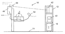
次に図5を参照すると、典型的なオペレータステーション14が示される。オペレータステーション14が、商品格納エリア23へ新たな商品を追加すること、および注文の一部または全部を履行するために商品格納エリア23から商品を取り出すことのどちらかに用いられるか、または両方に用いられるかに依存して、ピックおよび/またはプットステーションとして構成され得る。
Referring now to FIG. 5, a
図5に示すように、オペレータステーション14は複数の注文品箱46を含み、その各々が、注文の一部を成す商品を受け入れるために用いられる。理解されるように、注文を履行するための商品の取出しが自動化される場合、注文品箱46内への商品の載置はシステム10によって制御され、システム10は、同時に複数の注文を履行することができる。ピックおよび/またはプットステーションが複数の人間を収容できる場合も、複数の注文が同時に履行され得る。
As shown in FIG. 5, the
図5のオペレータステーション14は注文履行プロセス中が示され、ここで、注文の一部を成す商品42は、オペレータによって商品格納エリア23から取り出され、注文品箱46内に載置される。注文品箱46は、システム10のサーバによって注文に割り当てられる。オペレータステーション14は、オペレータステーション14における動作を制御および調整するように構成された制御ユニット48を含む。オペレータステーション14は、たとえばレーザポインタなどのポインティングデバイス50、および商品42に付された識別子をスキャンするように構成されたスキャナ52も含む。識別子は、ラインバーコードまたはたとえばQRコード(登録商標)などの二次元コードを含む任意のコンピュータ可読識別子であってよい。
The
商品42が搬送車両16によってオペレータステーション14へ搬送されると、現在履行中の注文の一部を成す商品42がポインティングデバイス50によって識別される。この例において、レーザポインタが商品42を指す。1つの実施形態において、レーザは、バーコードまたは二次元コードを含むがこれらに限定されないコードを指す。また、関連する複数の箱内に載置される複数の注文に関する商品42を識別するために、複数のレーザカラーが用いられ得る。様々なレーザカラーまたは他の区別的識別方法の使用は、同じ商品ラック12が、複数の注文を履行し得る同じまたは様々な商品を含む場合に有益である。
As the
識別された商品42をラック12から取り出した後、オペレータステーション14のオペレータは、スキャナ52を用いて商品42のバーコードまたは二次元コードをスキャンしてよい。そうすることで、商品42が制御ユニット48によって確認され、現在の注文に関する正しい商品42がラック12から取り出されたことが確実になる。その後、たとえば注文品箱46に光を照射することによって、商品42のための適切な注文品箱46がオペレータに示される。様々なレーザカラーの場合、注文品箱46への光は、対応する注文のために用いられたレーザカラーと一致するように構成されてよい。
After removing the identified
1つの実施形態によると、各マーカ20a〜20dは、第1のマーカから、たとえば第1のマーカと隣り合う位置にあるマーカなど1または複数の他のマーカへのナビゲーション経路を識別する関連ナビゲーション情報を有する。この方法では、全てのマーカ20a〜20dに関してマーカマップが形成され、各マーカ20a〜20dは、1または複数の所定の経路に沿った他のマーカに対する第1のマーカの位置を効果的に規定する関連情報を有する。
According to one embodiment, each
図6は、マーカマップのグラフ理論表現60を示す。グラフ60は、(各々がマーカ20a〜20dの1つを表す)ノード62と、辺66とを含む。辺66は、2つのマーカ20a〜20dの間に存在する連結部を示す。具体的には、2つのマーカを連結する辺66は、車両16が1つのマーカから他のマーカへ、他の任意の中間マーカを訪れることなく直接移動できることを示す。したがって、全体として考慮される辺は全て、互いに対するマーカ20a〜20dの位置を規定する。
FIG. 6 shows a graph
1つの実施形態によると、サーバは、様々なマーカ間の連結関係に対応するデータを(本明細書においてマーカマップと称される)データベース内に維持してよい。データは、バーコード(または固有識別情報)をキーとして有し、バーコードに関連する特性を値として有するキー値型データベースに格納され得る。特性は、ナビゲーションデータ内の近隣マーカのリストなど、特定の要件が満たすことができるように規定され得る。したがって、この実施形態では、マーカ位置を空間内の絶対位置として格納するのではなく、マーカ位置が互いに関連して格納される。そうすることで、本開示は、マーカ間の連結関係を効率的に識別する有利な能力をもたらす。したがって、サーバは、出発点マーカと到着点マーカとの間のルートを決定するためにマーカマップを利用する。 According to one embodiment, the server may maintain data in databases (referred to herein as marker maps) corresponding to the connectivity between the various markers. The data may be stored in a key-value type database that has the barcode (or unique identification information) as a key and the characteristic associated with the barcode as a value. Characteristics can be defined such that particular requirements can be met, such as a list of neighboring markers in the navigation data. Therefore, in this embodiment, rather than storing the marker positions as absolute positions in space, the marker positions are stored in relation to each other. In doing so, the present disclosure provides the advantageous ability to efficiently identify connectivity between markers. Therefore, the server utilizes the marker map to determine the route between the origin marker and the destination marker.
1つの実施形態によると、マーカマップは、たとえば倉庫の床などの面における検出可能点に関連する全てのデータを格納するデータベースシステムである。各点は、テリトリ内の二次元エリアを表す。第1のマーカからのコードは、マーカマップ内にあることを検証され得る。コードは、マーカに符号化される固有の文字列によって表されたマップ構造における1つの点であるバーコードであってよい。第1のマーカと隣り合う、または付近の近隣マーカ20a〜20dもまた、他の全てのマーカに対する各マーカのマーカ情報を格納することによってリスト化され得る。そうすることで、他のマーカまでの距離を計算する際に消費される処理電力および時間の節減がもたらされる。
According to one embodiment, the marker map is a database system that stores all data related to detectable points on surfaces such as warehouse floors. Each point represents a two-dimensional area within the territory. The code from the first marker can be verified to be in the marker map. The code may be a barcode, which is a point in the map structure represented by a unique string encoded in the marker. Neighboring
本明細書で説明されるマーカマップに関する実施形態は、マーカマップ内にバーコードが存在するかを決定し、更に、マーカの全ての近隣マーカのバーコードをリスト化することができる。特定のバーコードに関して、マーカマップは、特定のサイズのラックがバーコードの周囲を旋回した場合に影響を受ける近隣マーカをリスト化する。またマーカマップは、車両16の状態に依存して、特定の車両16が現在のバーコードから移動することができる近隣マーカもリスト化し得る。バーコードの各近隣に関して、マーカマップは、各近隣マーカにどのように到達するかに関するナビゲーション情報を格納する。ナビゲーション情報は、参照点に対して測定された向首角、移動距離などに関してよい。ただし、本明細書で説明される実施形態とともに他のナビゲーション識別が用いられ得ることを理解しなければならない。
Embodiments of the marker map described herein can determine if a barcode is present in the marker map, and can also list the barcodes of all markers adjacent to the marker. For a particular barcode, the marker map lists neighboring markers that are affected when a rack of a particular size swivels around the barcode. The marker map may also list neighboring markers that a
したがって、マーカマップは、2つのマーカ間のナビゲーション経路に関する情報も格納してよい。第1のマーカから各近隣マーカ20a〜20dへのナビゲーション経路および指示もリスト化されてよい。ラック12を運搬する上昇リフト、または下降リフトといった条件は、各近隣マーカ20a〜20dへのナビゲーション指示に含まれる。また、特定のサイズのラック12の旋回によって影響を受ける任意の近隣マーカ20a〜20dがリスト化され得る。
Therefore, the marker map may also store information regarding the navigation route between the two markers. Navigation routes and directions from the first marker to each of the neighboring
以下で、本開示の車両ナビゲーションシステムと併用され得るマーカマップ構造が1つの実施形態によって説明される。本明細書で説明される実施形態は特定のマップ構造に限定されないことを理解しなければならない。特定のマップ構造は、二次元空間において表現される。しかし、他の実施形態は、本明細書で説明される特定のマップ構造の3次元(またはより高次元の)拡張を利用し得る。 In the following, a marker map structure that can be used with the vehicle navigation system of the present disclosure will be described by one embodiment. It should be understood that the embodiments described herein are not limited to a particular map structure. A particular map structure is represented in a two-dimensional space. However, other embodiments may utilize a three-dimensional (or higher dimensional) extension of the particular map structure described herein.
表Iは、マーカに関して格納された情報を説明する典型的なマーカマップ構造を示す。説明のために、4つのマーカに対応する情報のみが表Iに示される。しかし、マーカマップは、他のバーコードに対応する情報を同様に格納してよいことを理解しなければならない。表Iにおいて、BARCODEは、マーカのバーコード番号に対応し、BOTIDは、現在バーコード上に位置する車両の識別番号に対応し、BLOCKEDは、バーコードが予約されているか否かを表し、NEIGHBOURSは、マーカの近隣に関する情報を格納する12ビットの2値フィールドであり、ZONEは、マーカが配置された倉庫内の地理的エリアを示し、SIZE_INFOの数値は、現在のバーコードが4つの(東西南北の)近隣バーコードから離れている距離であり、STORE_STATUSは、ラックをバーコードの上に置くことができるかを示す2値エンティティ(1はイエス、0はノー)である。 Table I shows a typical marker map structure that describes the information stored about the markers. For illustration purposes, only the information corresponding to the four markers is shown in Table I. However, it should be understood that the marker map may store information corresponding to other barcodes as well. In Table I, BARCODE corresponds to the bar code number of the marker, BOTID corresponds to the identification number of the vehicle currently located on the bar code, BLOCKED represents whether or not the bar code is reserved, and NEIGHBOOURS Is a 12-bit binary field that stores information about the neighborhood of the marker, ZONE indicates the geographical area within the warehouse where the marker is located, and the SIZE_INFO value is the current bar code of 4 (east-west). STORE_STATUS is the distance away from neighboring barcodes (north-south) and STORE_STATUS is a binary entity (1 for yes, 0 for no) that indicates whether the rack can be placed over the barcode.
1つの実施形態によると、フィールドNEIGHBORは12桁の2値フィールドであり、バーコードのそれぞれ北、南、東、および西方向において直接隣り合った各バーコードにつき3桁が確保される。しかし、これらの方向の各々における近隣が必ずしも各バーコードに存在するものではない。(方向に対応する)3桁の数字の各々は、(北方向に関して述べられた)以下の情報、(a)北方向にバーコードが存在するか(1はイエス、0はノー)、(b)車両がラックを伴わずに北のバーコードへ移動できるか(1はイエス、0はノー)、および(c)車両がラックを伴って北のバーコードへ移動できるか(1はイエス、0はノー)を表す。

図7は、他の典型的なマーカマップからの部分データを説明する、1つの実施形態に係る表70を示す。データは、各マーカ20a〜20dを他のマーカ20a〜20dに対して示すものである。マーカ20a〜20dの位置を示すナビゲーション情報および他のマーカ20a〜20dに対する相対位置がデータベースに格納される。
FIG. 7 shows a table 70 according to one embodiment illustrating partial data from another exemplary marker map. The data shows each of the
表70は、出発点マーカを識別する固有情報を含む出発点フィールド72、到着点マーカを指定する到着点フィールド74、および搬送車両が出発点マーカと到着点マーカとの間で比較的平坦な地面の上、エレベータの中、傾斜面の上を移動する必要があるかを示す通行方法フィールド76を含む。表70は、搬送車両16が出発点マーカから到着点マーカまでナビゲーション経路に沿って移動するために必要なナビゲーション情報を規定する方向、傾斜、および距離ナビゲーション値の詳細フィールド78も含む。表70は更に、かかる時間の観点からナビゲーション経路に沿って移動する搬送車両16のそれぞれの「コスト」を示すコストフィールド80を含む。
Table 70 shows a
図7に示す典型的なデータにおいて、商品格納エリア23は、いくつかの高さ(階数)の建物の上に配置されてよい。したがって、建物の様々な高さの間で移動するために、搬送車両16はエレベータで移動することを必要とし得る。そのため、エレベータ内にマーカが配置されてよい。表70に示すように、エレベータ内に配置されたマーカに関して、出発点フィールド72および到着点フィールド74は、たとえば21階など、エレベータが位置する現在の階数を示す情報も含む。詳細フィールド78は、エレベータを一意的に識別する情報も含む。他の実施形態において、各階に1または複数の車両16が割り当てられてよい。その結果、車両16を伴わず、ラック12のみしかエレベータで移動する必要がない。ラック12は、様々な車両16によって積み降ろしされてよく、この場合、第1の車両16が第1の階でエレベータにラック12を載せてよく、第2の車両16が第2の階でエレベータからラック12を降ろしてよい。
In the typical data shown in FIG. 7, the
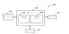
図8を参照すると、商品取り扱いシステムの管理システムの機能部品を示す典型的なブロック図81が示される。機能部品81は回路によって実装され、たとえば関連するプロセッサ(複数も可)、メモリ、およびデータストレージ(図16を参照して後述)を有する適切なコンピューティングデバイスなど、任意の適切な構成を用いる。実施形態において、機能部品81は、1または複数のデータベースと連動する1つ(または複数)のサーバを含む。本明細書で説明されるサーバは、任意の特定の組み合わせまたはハードウェア回路および/またはソフトウェアに限定されないことを理解しなければならない。
Referring to FIG. 8, an exemplary block diagram 81 illustrating functional components of a product handling system management system is shown.
機能部品81は、たとえばハードディスクドライブ(HDD)またはソリッドステートデバイス(SSD)などのデータストレージデバイス82を含み、これは図8においてデータベースとして表現されるが、理解されるように、任意の適切なデータストレージ構成が、本明細書で説明される実施形態によって考慮される。データストレージデバイス82は、図6および図7および表Iにおいて表現された種類のマーカマップを示すマーカデータ83を格納するように構成される。マーカマップ83は、各マーカ20a〜20dに関連する固有識別情報および他のマーカ20a〜20dとのナビゲーション関係を含み得る。
機能部品81は、新たな商品42を倉庫へ追加するプロセスを管理し、在庫データベース86に商品42の現在の在庫を記録する在庫マネージャ84も含む。在庫データベース86は、倉庫内のラック12のそれぞれの格納位置およびラック12における商品42の位置を示す情報も含む。このように、倉庫における全ての商品42の格納位置が知られている。
注文生成器88は、たとえば電子商取引ウェブサイトに関連するオンライン決済システムを介して受けた注文など、顧客からの注文の受領を管理する。作成された注文は、未決注文データベース92に注文エントリとして注文の詳細を格納する注文マネージャ90によって管理される。注文マネージャ90は、たとえばネットワークインタフェース112を介してポストされた注文など、クライアントによってポストされた注文を処理する。ネットワークインタフェース112は、到来する注文を処理するためにそれらをフォーマット化し、1または複数の注文アプリケーションプログラミングインタフェース(API)を用いてそれらをシステム10へポストする。注文は、未決注文リストにポストされる。
1つの実施形態によると、注文マネージャ90は、未決注文が処理される現在の条件下での最適な注文を見出すために、未決注文が処理される注文処理ループを形成する。大量の未決注文の場合、所望の結果を得るためにフィルタが用いられ得る。たとえば第1の典型的なフィルタは、到来ラックフィルタである。任意の未決注文が、既に注文処理ステーションにあるラックによって履行され得る場合、これらの注文が処理される機会を増やすためにこれらの注文は未決注文待ち行列のより高い位置に位置付けられ、必要なラック12の少なくとも1つが注文処理ステーションに置かれたままである。また、第2の典型的なフィルタは、クライアント優先度フィルタ、または特別に指定された注文が優先サービスのためにフラグ付けされる注文優先度フィルタである。第3の典型的なフィルタは、古い注文が新しい注文より先に処理される年代フィルタ(すなわち、現在の注文がどれほどの期間システム内で未決であるか)である。
According to one embodiment,
注文マネージャ90は、注文データベース92内の未決注文のタイミング履行も管理する。一例において、注文マネージャ90は、注文を履行するためにオペレータステーション14で注文品箱46が利用可能であることを示すためのトリガ信号が生成されると、未決注文の処理を開始するように構成される。
注文を履行し得る商品在庫のセットを入手するために優先順位付きの未決注文リストが注文処理ループへ送られる。本明細書において注文履行リスト(OFL)とも称される商品履行組み合わせ(IFC)を形成するために、(関連するラック12の識別を伴った)商品と様々な注文処理ステーションとの全ての組み合わせが生成される。各IFCについて、様々なラックの組み合わせ、すなわち、特定の注文処理ステーションにおける特定の注文に関する商品42を含むラックの組み合わせが生成される。
A prioritized pending order list is sent to the order processing loop to obtain a set of merchandise inventory that can fulfill the order. All combinations of merchandise (with associated
注文マネージャ90は、各未決注文の「コスト」を計算し、最小「コスト」に基づいて注文の履行を開始することによって、未決注文の履行の順序を管理する。注文「コスト」は、注文のために必要なラックの全てを指定のオペレータステーション14へ搬送するのにかかる時間に関連する。ただし、他の実施形態において、他のコスト要因が所要時間と置き換えられ、または所要時間とともに考慮されてよい。
実施形態において、「コスト」は、距離コスト、ラックコスト、およびピックおよび/またはプレイスステーション(PPS)負荷コストに副分割され得る。距離コストは、注文を履行するために選択されたラック12とPPSとの間で1または複数の車両16が走行する総距離を含み得る。ラックコストは、注文を履行するために使用されるラック12の総数を含む。より少ない数のラックを有するラック組み合わせによって、注文を履行する際の1または複数の車両16の移動時間が最小化される。PPS負荷コストは、最も近いまたは付近のPPSと、各PPSにおける利用状況または最小待ち時間との間の最適バランスを見出すことを含む。PPSは、注文処理ステーションの一例である。ただし、本明細書で説明される実施形態によって、出荷のための商品を調達し、集め、および/または準備するように構成された任意のステーションが考えられる。注文処理ステーションは、製造環境において商品を調達し、集め、および/または転送するために使用されてもよい。
In an embodiment, “cost” may be subdivided into distance costs, rack costs, and pick and/or place station (PPS) loading costs. The distance cost may include the total distance traveled by one or
処理するために選択された注文ごとに、オペレータステーション14が選択され、注文のために必要な商品42を含む1または複数のラック12が予約され、オペレータステーション14における注文品箱46が予約される。未決注文のコストを計算するために、まず商品42を提供する可能性がある全てのラック12が識別され、商品42を保持する識別されたラックのラックセットリストが規定される。ラックセットリストは、商品42ごとに規定される。その後、各ラックセットから選択されたラック12を備えるラック組み合わせは、ラック組み合わせごとに以下のヒューリスティックを計算することによって、決定されたラックセットから選択される。
Heuristic,H=Distance/(1+No.of Common Racks) (1)
式中、Distanceは、利用可能な注文品箱46からラック組み合わせ内の全てのラック12までの合計距離であり、No.of Common Racksは、複数のラックセットに共通のラック組み合わせ内のラック12の数である。ヒューリスティックHは、オペレータステーション14の利用可能な全ての注文品箱について計算される。
For each order selected for processing, an
Heuristic, H=Distance/(1+No. of Common Racks) (1)
In the formula, Distance is the total distance from the
1つの実施形態によると、最小または最も少ないヒューリスティックH値を有するラック組み合わせが選択され、選択されたラック組み合わせに関連する「コスト」は、組み合わせ内の全てのラック12が、選択された注文品箱46を有するオペレータステーション14へ移動するために必要な時間である。さらに、選択されたラック組み合わせ内に含まれるラック12は、予約データベース94において予約および識別される。同様に、選択されたオペレータステーション14およびオペレータステーション14の選択された注文品箱46もまた、予約データベース94において、選択されたオペレータステーション14および注文品箱46を指定することによって予約される。
According to one embodiment, the rack combination having the smallest or smallest heuristic H value is selected, and the "cost" associated with the selected rack combination is that all racks 12 in the combination have the selected order box. It is the time required to move to the
また、ブロック図81の機能部品は、処理するための注文が選択されると、注文を履行するために少なくとも1つの車両16を選択するタスクマネージャ96も含む。車両16は、利用状況、タスク優先度、およびタスクの「コスト」に基づいて選択される。利用可能な車両16が識別され、識別された利用可能な車両16の中から、現在空いている、または停止状態である車両16、および注文に関して選択されたラック組み合わせ内のラック12への車両16の近接度に基づいて、車両のセットが選択される。選択された各車両16は、商品格納エリア23から特定のラック12を取り出すタスクを割り当てられる。注文に関して選択された車両(複数も可)16は、割当て車両データベース98に格納される。
The functional components of block diagram 81 also include a
ブロック図81の機能部品は、車両マップ構造において、選択された車両16のためのナビゲーション経路の計画および予約を制御および調整するプランナ100も含む。プランナ100また、車両の発車/停車動作および車両の一時停車/停車解除動作に対する制御を含む、選択されたオペレータステーション14と行き来する車両16の移動の実行に関しても計画する。プランナ100はまた、車両16の充電状態の確認および充電が必要な車両16の車両充電ステーションへの移動を含む、車両16の充電を管理する。プランナ100は、車両16が準備完了状態になるまで待機すること、予約ステータスを変更およびタスクのステータスを更新すること、車両16の充電レベルを確認すること、および充電のタスクを割り当てることを含むがこれらに限定されない、割り当てられたタスクの実行を計画する。車両16の充電ステーションへの出入りのフローの管理もまたプランナ100によって制御される。
The functional components of block diagram 81 also include a
プランナ100は、注文を履行するために選択された車両のセットにおける車両16の各々のための搬送経路を計算する経路計算機102を含む。各搬送経路は、車両16が、商品格納エリア23内のラック格納位置へ、およびラック格納位置とオペレータステーション14との間でラック12を搬送するために辿るマーカ20a〜20dのシーケンスを規定する。各車両16のために計算された搬送経路は、規定経路データベース103に格納される。1つの実施形態によると、規定された各搬送経路の「コスト」は、最初の出発点から最終到着点までの移動にかかる時間に基づく。ナビゲーション経路の計算は更に、ラック12のリフト状態にも依存してよい。たとえば1つの実施形態によると、リフト状態が上がっている場合、他のラック12は全て、経路内に存在し得る物理的障害物とともに障害物として考慮される。ただし、リフト状態が下がっている場合、物理的障害物のみしか考慮される必要はない。
The
1つの実施形態によると、車両16のための搬送経路は、A*アルゴリズムを用いて計算される。アルゴリズムは、出発点マーカから到着点マーカまでのマーカ20a〜20dを通る効率的な経路を計算するために、図6に示すグラフ理論に従って規定され得る、マーカ20a〜20dの間の関係性を用いる。A*アルゴリズムは最良優先探索を用い、所与の初期ノードから、考えられる1または複数の目的地から選択された1つの目的地ノードへの最小コスト経路を割り出す。A*がグラフを横切ることによって部分経路のツリーが構築される。ツリーの(開集合またはフリンジと称される)リーフは、コスト関数によってリーフノードを順序付ける優先待ち行列に格納される。これは、目的地に到達するまでのコストおよび初期ノードからの移動距離のヒューリスティック推定値を結び付けるものである。
According to one embodiment, the transport path for
コスト関数は、f(n)=g(n)+h(n)によって表すことができ、式中、g(n)は、初期ノードからnに至るまでの既知のコストであり、この値はアルゴリズムによって追跡される。パラメータh(n)は、nから任意の目的地ノードに至るまでのコストのヒューリスティック推定値である。実際の最短経路を割り出すためのアルゴリズムの場合、ヒューリスティック関数は許容的でなくてはならず、これは、最も近い目的地ノードに至るまでの実際のコストを過大に見積もってはならないことを意味する。ヒューリスティック関数は問題特有であり、アルゴリズムのユーザによって提供される。 The cost function can be represented by f(n)=g(n)+h(n), where g(n) is the known cost from the initial node to n, and this value is the algorithm Tracked by. The parameter h(n) is a heuristic estimate of the cost from n to any destination node. For algorithms to determine the actual shortest path, the heuristic function must be tolerant, which means that the actual cost to reach the nearest destination node should not be overestimated. .. The heuristic function is problem-specific and is provided by the user of the algorithm.
プランナ100はまた、車両16のために規定されたそれぞれの搬送経路に個々に従って各車両16の移動を管理する車両ナビゲータ104も含む。車両ナビゲータ104は、搬送経路内のマーカ20a〜20dのシーケンスに沿った車両16の移動を制御すること、および車両16から受信する通信を処理することを請け負う。
The
車両16がマーカ20a〜20dに到着すると、車両16によってマーカ20a〜20dが検出され、たとえば検出されたマーカ20a〜20dに関連する固有識別情報および/または捕捉されたマーカ画像などのマーカ情報が、無線通信ネットワーク19を介して車両ナビゲータ104へ伝達される。受信した情報に基づいて、車両ナビゲータ104は、識別されたマーカ20a〜20dが搬送経路内の予想されるマーカ20a〜20dに対応することを確認し、搬送経路内の後続マーカ20a〜20dへ車両16を向けるために車両16へナビゲーション情報を伝達する。一例において、ナビゲーション情報は、マーカデータベース83に格納されたナビゲーション情報から導出された方位値および距離値の形式であり、図7に表形式で示される。すなわち、車両ナビゲータ104は、個別のマーカ20a〜20dごとに(すなわち、上述したようにヒップバイホップベースで)車両16へナビゲーション情報を送信する。
When the
車両ナビゲータ104はまた、マーカ20a〜20dに対する車両16の重心の位置、およびマーカ20a〜20dに対する車両16の方位も計算する。位置は、たとえば図9に示すセンサ/カメラ134などのセンサおよび/またはカメラによって捕捉された画像を用いて計算され得る。検出されたマーカ20a〜20dに対する車両16のオフセット位置は、図14を参照してその場所から計算され得る。車両16の現在位置は、車両位置データベース105に格納される。その結果、プランナ100は、全ての車両16の位置を常に知ることになる。
The
車両の経路に沿って車両16をナビゲートすることに加えて、車両ナビゲータ104は、車両16からのメッセージの受信および処理もする。1つの実施形態によると、車両16から受信される第1の種類のメッセージは、開始メッセージである。開始メッセージは、車両16が始動または再起動すると車両ナビゲータ104へ送信される。開始メッセージは、スキャンされたマーカに対応する情報を含むデータパケットとして送信されてよい。スキャンされたマーカが有効である場合、開始メッセージは車両マネージャ110によって処理され、車両マネージャ110はその後ナビゲーション方向を車両へ送信する。
In addition to navigating the
車両ナビゲータ104によって受信される車両16からの第2の種類のメッセージは、警告メッセージである。車両16が、車両16のために予約されていない有効ナビゲーションマーカに到達すると、車両ナビゲータ104によって警告データパケットが受信される。この状況において、車両16が位置するナビゲーションマーカが予約されてよく、可能であれば、ナビゲーション経路内の次のナビゲーションマーカも予約される。しかし、現在のナビゲーションマーカが他の車両16によって予約されている場合、第1の車両16は、更なる移動を阻止される。
The second type of message from the
車両ナビゲータ104によって受信される車両16からの第3の種類のメッセージは、情報メッセージである。情報データパケットは、車両16がラック12を持ち上げ、または運搬中である場合、ラック12の位置を更新するために車両ナビゲータ104へ送信される。車両ナビゲータ104は、ラック12の動きに関係している人員および車両マネージャ110に、完了すべき任意の関連タスクを確認するように通知する。また情報パケットは、旧位置が存在する場合それを予約解除し、順番予約が完了するとそれを予約解除することもできる。車両ナビゲータ104は、たとえば割当て車両データベース98、車両位置データベース105、規定搬送経路データベース103、または予約経路およびマーカデータベース108などの関連車両データベースにおける車両16の情報を更新する。また車両ナビゲータ104は、到着点ナビゲーションマーカに到達したか、または次の予約ナビゲーションマーカに到達したかを決定することもできる。
The third type of message from the
車両ナビゲータ104によって受信される車両16からの第4の種類のメッセージは、エラーメッセージである。無効ナビゲーションマーカのバーコードが車両16によって読み取られると、車両ナビゲータ104によってエラーメッセージが受信される。車両16への指示が車両16によって処理されることができなかった場合も、車両ナビゲータ104へエラーパケットが送信され得る。
A fourth type of message from the
また車両ナビゲータ104は、衝突が回避されるように車両16の移動を管理するようにも構成され得る。1つの実施形態において、衝突管理は経路およびマーカ予約を管理することによって実現され、それによって(本明細書においてセグメントと称される)2つのマーカ間の各ナビゲーション経路は、車両16が到着する直前に予約される。ただし、後続するナビゲーション経路(すなわちナビゲーション経路のセグメント)内での移動は、ナビゲーション経路が予約されるまで許可されない。ナビゲーション経路が他の車両16によって既に予約されている場合、ナビゲーション経路を予約しようと望む車両16は待機状態に入る。ただし、特定の実施形態において、たとえば既存の予約を用いて履行中である注文よりも高い優先度が特定の注文に割り当てられている場合、優先度情報に基づいて過去の予約が取り消され、再スケジュールされてもよい。1つの実施形態によると、倉庫の特定の区分における特定の経路は、修理またはサポートのために取り除かれてよい。
The
また、各車両16のためのエンドツーエンド(すなわち出発点マーカから到着点マーカまでの)搬送経路は一度には予約されないので、2台の車両16が同様の経路に沿って逆方向に移動しようと望むことによるデッドロック状況が存在し得ることを理解しなければならない。デッドロックを解消するために、一方の車両16が経路を外れて移動する必要がある。したがって、車両ナビゲータ104は、デッドロック状況に関与する車両16の一方を指定経路から離れるように能動的に制御し、それによってデッドロック状況における他方の車両16が自身の指定搬送経路に従って移動することを可能にする。
Also, the end-to-end (ie, the departure marker to the arrival marker) transport route for each
1つの実施形態によると、車両ナビゲータ104は、デッドロック状況の発生を能動的に回避するように構成され得る。車両ナビゲータ104が車両16のためにマーカ20a〜20dを予約しようと試みる場合、車両ナビゲータ104は、他の車両16もまた、マーカ20a〜20dを通過するように規定された搬送経路を有するかを確認する。そうである場合、車両ナビゲータ104は、安全予約として車両16のためにマーカ20a〜20dを予約する。安全予約として予約されたマーカ20a〜20dに関して、他の車両16が安全予約されたマーカ20a〜20dから出ることができるマーカ20a〜20dも予約されていない限り、他の車両16は安全予約中のマーカ20a〜20dを予約することはできない。すなわち、安全予約が行われると、他の車両16は、安全予約された領域に留まることを許可されない。また、予約されたマーカ20a〜20dおよびナビゲーション経路に基づいて車両16の移動を管理すること、および車両16の移動のタイミングを制御することによって、衝突およびデッドロックが回避され得る。その結果、車両16を待機させること、または車両16の移動速度を能動的に修正することによって、衝突が回避され得る。
According to one embodiment, the
本開示の実施形態によると、ナビゲーション経路を処理する際、車両ナビゲータ104によってナビゲーション変数が用いられ得る。本明細書においてセグメント長さ変数と称される第1の変数は、車両16のために予約されるナビゲーション経路の長さに対応する。本明細書において予約距離変数と称される第2の変数は、ナビゲーション経路の終点までの距離に対応する。ナビゲーション経路が決定された後、ナビゲーション経路内の第1のセグメント長さが予約される。次のセグメントとともに、次の予約が行われるナビゲーションマーカが計算される。車両16が次の予約位置に到達すると、他の予約距離が計算される。上記プロセスは、車両16がナビゲーション経路の到着点に到達するまで継続する。
According to embodiments of the present disclosure, navigation variables may be used by
また、ナビゲーション経路内に曲がり角が存在する場合、近隣ナビゲーションマーカに関して予約距離が計算される。予約されるナビゲーション経路セグメント内に、移動中の車両16または角を曲がっている車両16が発見された場合、予約は行われず、不履行位置が計算される。また、1つの実施形態によると、到着点にアイドル車両がある場合、計算を完了することができない。車両16はアイドル状態に設定されるか、あるいは待機状態に入る。1つの実施形態によると、予約されるセグメント内にアイドル車両16が発見された場合、新たな経路が計算される。
Also, if there is a turn in the navigation route, the reservation distance is calculated for the neighboring navigation markers. If a moving
プランナ100はまた、車両16間の衝突を回避するために、マーカ20a〜20dの予約およびマーカ20a〜20d間のナビゲーション経路を管理する予約マネージャ106も含む。プランナ100は、予約経路およびマーカデータベース108内に、予約されたマーカ20a〜20dおよびナビゲーション経路を示す情報を格納する。
The
プランナ100はまた、車両の発車および停車動作を制御し、車両16の接触板36の動きを上昇位置と下降位置との間で制御する車両マネージャ110も含む。車両マネージャ110はまた、車両16の充電レベルも管理し、これは、車両16の充電状態を確認することおよび充電が必要な車両16の車両充電ステーションへの移動を管理することを含む。また、図8に示すように、管理システム18のブロック図81の機能部品は、管理システム18、車両16、およびオペレータステーション14の間のネットワーク通信を容易にするネットワークインタフェース112も含んでよい。
The
たとえば搬送車両または搬送ロボットなどの車両16の機能部品118が図9に示される。機能部品118は、車両16および管理システム18の各々とオペレータステーション14との間のネットワーク通信を容易にするネットワークインタフェース120を含む。(図16を参照して後述される、回路によって実装される)マイクロコントローラ122は、車両16における動作を制御および調整し、たとえばマーカ20a〜20dの検出を管理すること、車両ナビゲータ104から受信した指示に従って車両の移動の制御を管理すること、およびマーカ20a〜20d間で決定された搬送経路に、ベジェ曲線を用いて再計算されたナビゲーション経路などの補償経路を適用することなどの専用タスクを実行する。マイクロコントローラ122は、車両の車輪34に付随する1または複数のモータ126を制御するためにモータドライバ124と通信し、それによって車両16の速度および方向を制御する。
The
機能部品118はまた、マイクロコントローラ122からの指示に応答して接触板36を制御可能に上昇または下降させるリフトデバイス130も含む。マイクロコントローラ122からの指示は、車両マネージャ110から受信した指示に応答して生成され得る。
機能部品118はまた、車両16がマーカ20a〜20dに近づくとマーカ20a〜20dを検出するように構成された、たとえばカメラまたはRFIDリーダなどの少なくとも1つのセンサ134も含む。センサ/カメラ134は、マーカ20a〜20dに関連する固有識別情報を取得し得る。取得された固有識別情報はマイクロコントローラ122によってプランナ100へ伝達され、それによって車両16の現在位置が決定され得る。
センサ(複数も可)/カメラ134はまた、車両16の位置と検出されたマーカ20a〜20dの位置との間のオフセットを決定するためにも用いられ得る。オフセットは、検出されたマーカ20a〜20dと搬送経路内の後続マーカ20a〜20dとの間で既定された搬送経路を修正するために用いられ得る(図14を参照して後述)。これは、マーカ20a〜20dを含む画像を捕捉すること、および画像を処理するためにプランナ100へ転送することによって実現される。1つの実施形態において、オフセットは車両16によって計算される。車両16に対する捕捉画像の位置および方位が知られるので、車両16に対するマーカ20a〜20dの位置および方位を決定することが可能である。
The sensor(s)/
機能部品118はまた、車両16がラック12を搬送している場合、重量測定値を生成するはかり138も含む。重量測定値は、たとえば車両16によって搬送中のラック12の重量を考慮した適切な加速および減速パラメータなど、荷積み車両16のための移動パラメータを計算するためにマイクロコントローラ122によって用いられ得る。移動パラメータは、接触板36が上昇位置にあるか下降位置にあるかに基づいて計算されてもよい。
はかり138はまた、空のラック12の既知の重心、各商品42の既知の重量、およびラック12における商品42の位置を用いることによって、重量分布プロファイルを決定するためにも用いられ得る。重量分布プロファイルは、ラックおよび積載商品42の重心を計算するために用いることができ、これはその後、荷積みラック12の重心が規定の範囲内にあることを確実にするために用いられる。そうすることで、荷積みラック12が搬送中に過度にバウンドしないことが確実である。
1つの実施形態によると、荷積みラック12の重心のz成分は、ラック12における商品42の位置を調整することによって、重心が高すぎないように操作され得る。荷積みラックの重心(COG)は、ラック上の基準点およびラック12における商品42の分布(すなわち各商品のCOG)に基づいて計算され得ることを理解しなければならない。加えて、重心のx−y成分に関連して、商品42がラック12に追加され、またはラック12から取り出される度に、ラック12における商品42受入れ位置の全てについてコスト値が計算され得る。コスト値は、荷積みラック12が重心からずれている量に対応してよい。
According to one embodiment, the z-component of the center of gravity of the
マイクロコントローラ122は、プランナ100からの指示に応答するモータ126の制御、プランナ100からの指示に応答するリフトデバイス130の制御、センサ/カメラ134およびはかり138との通信の管理、およびネットワークインタフェース120との通信の管理を含む、車両16における規定の機能を実装するように構成されてよい。
The
オペレータステーション14の機能部品139が図10に示される。機能部品139は、オペレータステーション14、管理システム18、および車両16の間のネットワーク通信を容易にするネットワークインタフェース140を含む。制御ユニット142は、オペレータステーション14における動作を制御および調整する。制御ユニット142は、たとえば入荷商品プロセス144および出荷商品プロセス146などの規定の機能を実装するように構成される。
The
入荷商品プロセス144は、物理的意味および電子的意味の両方において、商品取り扱いシステム10内への新たな在庫商品の受取りを管理する。物理的意味では、選択されたラック12に新たな商品42が載置され、ラック12が商品格納エリア23内の格納位置へ搬送される。電子的意味では、商品42の存在および位置が在庫データベース86に記録される。
The incoming goods process 144 manages the receipt of new inventory goods into the
出荷商品プロセス146は、物理的意味および電子的意味の両方において、商品取り扱いシステム10からの商品42の取出しを管理する。物理的意味では、注文の一部を成す商品42が、商品格納エリア23内のラック12から取り出される。電子的意味では、取り出された商品の記録が、在庫データベース86から消去される。
The shipped
機能部品139はまた、ポインティングデバイス50およびスキャナ52も含む。ポインティングデバイス50は、ラック(複数も可)12からの正しい商品(複数も可)42の取出しおよびラック(複数も可)12の正しい位置への商品42の載置を調整するために入荷商品プロセス144および出荷商品プロセス146に関連して動作する。スキャナ52は、注文履行中に商品42がラック12から取り出され、または新たな在庫の追加中にラック12に載置されると、たとえば商品42のバーコードなど、商品42の識別子をスキャンするように構成される。スキャンされたバーコードによって、オペレータステーション14は、スキャンされた商品42が正しいかを検査および確認することが可能である。コードをスキャンすることに加えて、またはその代替として、スキャンされた商品42が正しいかを確認するために物体認識デバイスが用いられ得る。
図11は、商品取り扱いシステム10によって実装される在庫プロセスにおいて実行されるステップを示す典型的なフローチャート160を示す。
FIG. 11 shows an
ステップ162において、商品42の新たな在庫が倉庫に到着する。ステップ164において、到着した商品42ごとに、オペレータステーション14のオペレータは、スキャナ52を用いて、たとえば商品42のバーコードなどの識別子をスキャンする。オペレータステーション14は、商品42を示す情報を管理システム18の在庫マネージャ84へ伝達する。在庫マネージャ84は、商品42の記録を在庫データベース86に追加し、商品格納エリア23における商品42の所望の位置をオペレータステーション14へ伝達する。たとえば、商品42が格納されるべきラック12およびラック12における商品42の載置位置がオペレータステーション14へ伝達される。実施形態において、ラック12における全商品42の構成を最適化するために、1または複数の商品42の配置を変更するように在庫マネージャ84によって指示が与えられ得る。
In
また、ステップ166において、管理システム18から受信した位置の通信に基づいて、入荷商品プロセス144は車両16に、商品格納エリア23から関連ラック12を取り出すように指示する。ラック12がオペレータステーション14へ搬送168された後、ステップ168において、ポインティングデバイス50は、商品42が載置されるべきラック12上の位置を示す。たとえば、ステップ170において、レーザポインタは、商品42が載置されるべきラック12上の位置を指し得る。
Also, in
ステップ172において、他の商品42が同じラック12に格納されるかが決定される。他の商品42が同じラック12に載置される場合、ステップ174において、追加の商品42がスキャンされ、ポインティングデバイス50によってオペレータに示されたラック12における特定の位置に載置される。同じラック12に載置される追加の商品42がない場合、ステップ176において、ラック12は、商品格納エリア23内の規定の格納位置へ返送される。ステップ178において、新たな在庫に追加の商品42が存在するかが決定される。ステップ178において、商品格納エリア23に格納される新たな在庫商品42ごとにプロセスは繰り返される。新たな在庫に追加の商品42がない場合、ステップ180においてプロセスは終了する。
At
図12は、商品取り扱いシステム10によって実装される商品ピッキングプロセスのステップ192〜212を説明するフロー図190を示す。1つの実施形態によると、注文処理サーバは、到来する注文を注文待ち行列に追加する。ステップ192において、管理システム18の注文マネージャ90によって、注文は処理のためにトリガされる。注文処理サーバは、注文待ち行列内の注文を履行するために最適なラック(すなわち、最小ラックコストを有するラック)のセットを決定する。最適なラックのセットが決定されると、タスク割当てサーバは、在庫取出しプロセスのためにオペレータステーション14へラックのセットを運搬するための最適な車両のセットを計算する。経路計算サーバは、ナビゲーション経路内で重複する領域がない、選択された車両のための最も効率的なナビゲーション経路を計算する。
FIG. 12 shows a flow diagram 190 illustrating steps 192-212 of the product picking process implemented by the
注文の一部を成す商品42に関して、ステップ194において、車両ナビゲータ104は、注文内の商品42を含む選択されたラック12を商品格納エリア23から取り出すように車両16に指示する。ステップ194は、マーカ20a〜20dの間を移動するための連続ナビゲーション経路を示すように車両16に順次ナビゲーション指示を通信することによって実現され得る。車両16が選択されたラック12に到達すると、選択されたラック12は、選択されたラック12の下にあるナビゲーションマーカを用いて識別される。車両ナビゲータ104は、ラックのリフトおよび搬送中に選択されたラック12が確実に位置を合わせられるように、ナビゲーションマーカからのデータを用いて車両の重心と選択されたラック12の中心との位置を合わせる。選択されたラック12は、車両16のリフトヘッドの高さを高くすることによって地面から持ち上げられる。一例として、選択されたラックは、搬送のために地面から約5〜10cm持ち上げられる。
For
ステップ196において、車両16は、商品42を含む選択されたラック12をオペレータステーション14へ搬送する。車両は、関連する車両16ごとに過去に計算された加速および減速プロファイルを用いて、選択されたラック12をオペレータステーション14へ運搬する。ステップ198において、選択されたラック12がオペレータステーション14に到着すると、各車両16の制御は、待ち行列管理サーバへ移行される。待ち行列管理サーバは、車両16を注文処理待ち行列に移動させる。車両16がオペレータステーション14のピックポイントに到達すると、ステップ200において、ポインティングデバイス50は、商品42が載置されるラック12上の位置を指す。一例において、ラック12上の位置にレーザポインタが向けられる。
At
ステップ202において、オペレータステーション14のオペレータは、識別された商品42をラック12から取り出し、商品42に設けられた識別子をスキャンする。それに応答して、ステップ204において、オペレータステーション14は、正しい商品42が選択されたかを確認するために商品42を示す情報を伝達する。商品が正しいと確認された場合、商品42を示す情報は、管理システム18の在庫マネージャ84へも伝達され、在庫マネージャ84は、在庫データベース86から商品42の記録を消去する。
In
ステップ206において、他の商品42が同じラック12に格納されているかが決定される。追加の商品42が同じラック12から取り出される場合、ポインティングデバイス50は、取り出される追加の商品42があるラック12上の位置を示し、追加の商品42ごとに上記プロセスが繰り返される。
At
また、1つの実施形態によると、ラック上の商品42は、最適な配置ではないことがある。たとえば、追加された商品42の在庫は、元々最適な位置に載置されていてよい。しかし、更に追加された在庫によって、ラック空間が可能な最大限まで利用されず、または重心がずれてバランスを欠くことがある。したがって、在庫マネージャ84は、ラック12上の商品42の一部または全部を再構成するように指示を送信してよい。
Also, according to one embodiment, the
また、同じラック12から取り出される追加の商品42がない場合、ステップ208において、ラック12は、商品格納エリア23内の規定の格納位置に返送される。ステップ210において、注文内に追加の商品42があるかがステップ210において決定される。プロセスは、商品格納エリア23から取り出される注文内の追加の新たな商品42ごとに繰り返される。注文内に追加の商品42がない場合、ステップ212においてプロセスは終了する。
If there is no
次に図13Aおよび図13Bを参照すると、注文履行プロセスおよび車両の移動の制御において実行されるステップを示すフローチャート220が示される。
Referring now to FIGS. 13A and 13B, a
ステップ222において、たとえば電子商取引ウェブサイトを介して、注文生成器88を用いて管理システム18において注文が受信される。受信された注文は、注文マネージャ90によって注文データベース92に記録され、ステップ224において注文待ち行列に入れられる。ステップ226において、注文がトリガされたかが決定される。注文が履行のためにトリガされた場合、ステップ228においてタスクマネージャ96は、上述したヒューリスティック算法に基づいて注文の履行のために好適なラック組み合わせを決定する。ステップ230において、タスクマネージャ96は、ラック12に対する車両16の位置に基づいて、決定されたラック12の各々の取出しを実行するための車両16の最適なセットを決定する。
At
ステップ232において、ラック組み合わせ内の各ラック12について、管理システム18における経路計算機102は、ラック12の取出し中に各車両16が辿る搬送経路を計算する。また、商品格納エリア23へ戻る車両16の搬送経路も決定される。実施形態において、搬送経路は、A*アルゴリズムを用いて計算される。搬送経路は、車両16が自身の現在位置から商品格納エリア23内の関連ラック12へ移動するために通過するマーカ20a〜20dのシーケンス、または車両16が商品格納エリア23からオペレータステーション14へ移動するために通過するマーカ20a〜20dのシーケンスを規定する。
In
ステップ234において、商品格納エリア23からラック12を取り出すために割り当てられた各車両16について、車両ナビゲータ104は、現在のマーカ20a〜20dから規定搬送経路における後続マーカ20a〜20dへ移動するためのセグメント化ナビゲーション経路を示すナビゲーション指示を車両16へ伝達する。そのようなナビゲーション情報は、たとえば方位形式の方向情報、および現在のマーカ20a〜20dと後続マーカ20a〜20dとの間の距離を示す距離情報を含む。ステップ236において、車両16が後続マーカ20a〜20dに到着すると、車両16はセンサ134を用いて後続マーカ20a〜20dに関連する固有識別情報を読み取り、後続マーカ20a〜20dを示す情報を車両ナビゲータ104へ伝達する。
In
ステップ238において、取り出されることが決定されたラック12のマーカ20bに車両16が到着したかが決定される。後続マーカ20a〜20dが決定されたラックマーカ20bではない場合、車両ナビゲータ104は、車両16が規定搬送経路において現在のマーカ20a〜20dから更に後続のマーカ20a〜20dへどのように移動するかを示す追加のナビゲーション指示を車両16へ伝達する。このプロセスは、決定されたラックマーカ20bの後続マーカ20a〜20dに到着するまで継続する。マーカ20a〜20dが全て避けられ、車両16が一時的に「行方不明」になると、車両16は停車するように指示され、および/または車両16の位置センサが検索され得る。
At
車両16が、取り出すべきラック12の下に配置されたラックマーカ20bに到着すると、位置決定器132は、ラック12に対する車両16の位置を決定し、必要であれば、ステップ240において、車両16とラック12との位置が正確に合うように車両16はラック12に対して移動する。車両16とラック12との位置を正確に合わせる際、車両16のセンサ134が位置決定器132を補助する。位置合わせ後、ステップ242において、車両マネージャ110は、接触板36を下降位置から上昇位置へ上げることによってラック12を地面から持ち上げるように車両16に指示するための通信を車両16へ送信する。
When the
車両16は、更なる規定搬送経路に沿ってオペレータステーション14へ向かって移動する。ステップ244において、車両ナビゲータ104は、現在のラックマーカ20bから規定搬送経路における後続マーカ20a〜20dへどのように移動するかを車両16に示すナビゲーション指示を車両16へ伝達する。ナビゲーション情報は、たとえば方位形式の方向情報、および現在のマーカ20a〜20dと後続マーカ20a〜20dとの間の距離を示す距離情報を含み得る。車両16が後続マーカ20a〜20dに到着すると、ステップ246において、車両16はマーカ20a〜20dを読み取り、マーカ20a〜20dを示す情報を車両ナビゲータ104へ伝達する。ステップ248において、車両16が待ち行列入口マーカ20cに到着したかが決定される。車両16が待ち行列入口マーカ20cに到着していない場合、後続マーカ20a〜20dが待ち行列入口マーカ20cになるまでプロセスは継続する。
The
車両16が待ち行列入口マーカ20cに到着すると、ステップ250において、車両16の移動に対する制御は、管理システム18からオペレータステーション14へ移行する。ステップ252において、オペレータステーション14は、オペレータに隣接するピックポイントへ順次移動するように、ステーション待ち行列22内の車両16および関連ラック12に指示する。ステップ254において、車両16がピックポイントに到着したかが決定される。ラック12を有する車両がピックポイントに到着すると、ステップ256において、ポインティングデバイス50は、取り出すべき商品42が存在するラック上の位置を示す。これは、レーザポインタをラック12上の位置に向けることによって実行され得る。ステップ258において、オペレータステーション14のオペレータは、商品42を取り、スキャンする。オペレータステーション14は、ステップ260において、ラック12から取り出された商品42が正しいかを確認する。商品42が正しい場合、オペレータは、割り当てられた注文品箱46内に商品を載置する。
When the
ステップ262において、ラック12から更に取り出す商品42があるかが決定される。更に取り出す商品がある場合、同じラック12から取り出される追加の商品42ごとにプロセスは繰り返される。ラック12から更に取り出される商品42がない場合、ステップ264において、車両16およびラック12はオペレータステーションによって制御され、ステーション待ち行列22の出口における待ち行列出口マーカ20dへ移動する。車両が待ち行列出口マーカ20dを検出すると、ステップ266において、車両の移動に対する制御は、オペレータステーション14から管理システム18へ移行する。
At step 262, it is determined if there are
ステップ268において、車両ナビゲータ104は、現在のマーカ20a〜20dから次のマーカ20a〜20dへの移動の方向および距離を示す移動情報を車両16へ伝達する。ステップ270において、車両16がマーカ20a〜20dに到着すると、車両16はマーカ20a〜20dを読み取り、マーカ20a〜20dを示す情報を車両ナビゲータ104へ伝達する。
In step 268, the
ステップ272において、車両16がラックマーカ20bに到着したかが決定される。車両16がラックマーカ20bに到着していない場合、ラックマーカ20bに到達するまでプロセスは繰り返される。車両16は、ラック12を商品格納エリア23内の関連格納位置へ返送する。ステップ274において、商品格納エリア23内の格納位置において車両マネージャ110は、接触板36を下げることによってラック12を地面に降ろすように車両16に指示するための通信を車両16へ送信する。
At step 272, it is determined whether the
ステップ276において、他のラック12から更に取り出される商品42があるかが決定される。他のラック12からの追加の商品42が注文に含まれる場合、注文内の全ての商品42が注文品箱46内に載置されるまで、商品格納エリア23からオペレータステーション14へ、および再び商品格納エリア23への各他のラック12の搬送についてプロセスが繰り返される。全ての商品42が注文品箱46内に載置されると、ステップ278において注文は完了する。
At step 276, it is determined if there are any
図13A〜図13Bのプロセスは、簡潔性のために1台のみの車両16に関して説明された。しかし、作業環境において、数台の車両16が同時にまたは連続した交互の動作で車両ナビゲータ104によって操作され、注文の履行または任務の遂行を果たし得る。
The process of FIGS. 13A-13B has been described with respect to only one
図14は、車両のナビゲーション経路を補償するために用いられる方法を示す図である。図14は、第1のマーカ282に近接した車両16を示す。車両16は、第2の後続マーカ284に向かって移動している。図内のナビゲーション経路285は、第1のマーカ282と第2のマーカ284との間の直線である。
FIG. 14 is a diagram illustrating a method used to compensate for a vehicle navigation route. FIG. 14 shows the
図14に示すように、車両16の重心286は、
![]()
![]()
実施形態において、未補正ナビゲーション経路285に適用するための補正経路288は、第1のマーカ282から重心286までのx軸方向のオフセット距離ΔX、および第1のマーカ282から重心286までのy軸方向のオフセット距離ΔYを用いて計算される。また、搬送車両16の方向ベクトルと(Vfとして示される)未補正ナビゲーション経路285の方向ベクトルとの差(すなわち角度差)が、未補正ナビゲーション経路285からの角度シータとして示される。角度シータもまた、補正経路288を計算するために用いられる。1つの実施形態によると、補正経路288は、上記の情報に基づいて生成されるベジェ曲線である。
In the embodiment, the correction path 288 for application to the uncorrected navigation path 285 is an offset distance ΔX in the x-axis direction from the first marker 282 to the center of gravity 286 and a y-axis from the first marker 282 to the center of gravity 286. Calculated using the directional offset distance ΔY. Also, the difference (ie, the angular difference) between the direction vector of the
1つの実施形態によると、補正経路288は、累積速度プロファイルから計算されてよい。累積速度プロファイルは、たとえば車両16がラック12を運搬しているか、している場合はラック12の重量など、特定の変数を考慮し得る。ただし、車両16がラック12を運搬している場合、補正経路288は、ナビゲーション経路内に存在し得る他の任意の物理的障害物を考慮するとともに、ナビゲーション経路内の他の任意のラック12を障害物として考慮する必要がある。車両16がラック12を運搬していない場合、物理的障害物のみしか考慮する必要はない。
According to one embodiment, the correction path 288 may be calculated from the cumulative velocity profile. The cumulative velocity profile may take into account certain variables, such as the weight of the
1つの実施形態によると、補償経路の計算において考慮される他の変数は、ナビゲーション経路において通行するマーカセグメントの数である。後述するように、これらの変数ならびに他の関連変数から、加速距離および加速率、ならびに減速距離および減速率が計算され得る。実施形態において、時間単位ごとの加速の度合い、および時間単位ごとの減速の度合いが得られ得る。たとえば、時間単位ごとに3つの度合いの加速および減速が決められてよい。しかし、時間単位ごとの加速および減速を決めるために他の度合いが用いられてもよい。したがって、累積速度プロファイルは、計算された加速プロファイル、減速プロファイル、および一定速度プロファイルから得られ得る。計算された累積速度プロファイルの適用により、3つの程度のベジェ曲線が生じ得る。その結果、ベジェ曲線は、補正経路288を得るために、投射される地上における車両の質点の中心の動きに関する参照であってよい。上記プロセスは、車両16が自身のナビゲーション経路における新たなマーカ20a〜20dに到達する度に繰り返される。
According to one embodiment, another variable considered in the calculation of the compensation route is the number of marker segments traversed in the navigation route. From these variables and other related variables, acceleration distance and acceleration rate, and deceleration distance and deceleration rate can be calculated, as described below. In an embodiment, a degree of acceleration per time unit and a degree of deceleration per time unit may be obtained. For example, three degrees of acceleration and deceleration may be determined for each time unit. However, other degrees may be used to determine the acceleration and deceleration for each time unit. Therefore, the cumulative velocity profile may be obtained from the calculated acceleration profile, deceleration profile, and constant velocity profile. Application of the calculated cumulative velocity profile can result in three degrees of Bezier curves. As a result, the Bezier curve may be a reference for the movement of the center of mass of the vehicle on the projected ground in order to obtain the correction path 288. The above process is repeated each time the
1つの実施形態によると、隣接するマーカ282と284との間のナビゲーション経路は、複数のセグメントに分割される。一例において、2つの隣接するマーカ間のナビゲーション経路は、500のセグメントに分割され得る。車両16の移動が開始すると、タイマおよび車輪カウンタが起動する。車輪カウンタは、車両16の各車輪に関する回転数を計測する。合計車輪回転は、車両16が移動する方向および距離に関係し得る。
According to one embodiment, the navigation path between
また、セグメントカウンタは、現在のセグメントの記録を維持する。車輪34のそれぞれの速度は、各セグメントの始点で設定され得る。たとえば500μsごとなど所定の時間後、タイマは中断され、車輪カウントが読み取られる。車輪カウントが予想されたカウントと少なくとも等しい場合、セグメントカウンタはインクリメントされる。たとえば補正後ナビゲーション経路の約95%など、補正後ナビゲーション経路の規定の量が完了した後、車両16は、車両ナビゲータ104によって、第2のマーカ284を検出するよう試みるように指示される。
The segment counter also keeps a record of the current segment. The speed of each of the
1つの実施形態によると、以下のパラメータを考慮することによって計算が実行され得る。パラメータNoMは、直線経路で通行するステップ(すなわちマーカ)の数に対応し(ただしNoMは少なくとも1)、パラメータXは、加速距離に対応する定数であり(たとえば、Xに値120が割り当てられるものとし)、パラメータYは、減速距離に対応する定数であり(たとえば、Yに値120が割り当てられるものとし)、パラメータstart_speedに値15が割り当てられ、パラメータmax_speedに値100が割り当てられ、パラメータstop_speedに値7が割り当てられるものとする。
According to one embodiment, the calculation may be performed by considering the following parameters. The parameter NoM corresponds to the number of steps (i.e., markers) traveling in a straight path (where NoM is at least 1) and the parameter X is a constant corresponding to the acceleration distance (e.g. X is assigned the value 120). The parameter Y is a constant corresponding to the deceleration distance (for example, the
初期加速減速プロファイルは、以下のように加速距離(AD)、減速距離(DD)、および最高速度(MS)を計算することによって決定される。
AD=minimum(X,X*0.5*NoM) (2)
DD=minimum(Y,Y*0.5*NoM) (3)
MS=minimum(max_speed,start_speed*(4*NoM) (4)
その結果、1つの実施形態によると、加速減速プロファイルは、直線で通行するマーカの数に基づいて計算される。
The initial acceleration/deceleration profile is determined by calculating the acceleration distance (AD), deceleration distance (DD), and maximum speed (MS) as follows.
AD=minimum(X,X * 0.5 * NoM) (2)
DD=minimum (Y, Y * 0.5 * NoM) (3)
MS=minimum(max_speed, start_speed * (4 * NoM) (4)
As a result, according to one embodiment, the acceleration/deceleration profile is calculated based on the number of markers passing in a straight line.
また、補償曲線を生成するために、2つのマーカ間の距離(たとえば、マーカ282と284との間の距離)は、所定の数のセグメントに分割される。また、所定の数の補間点が選択される。1つの実施形態によると、4つの補間点が選択される。ただし、選択される点の数は、補償曲線の滑らかさに影響する。本明細書で説明される実施形態は、4つの補間点の選択に限定されるものではなく、他の任意の数の補間点が選択されてよいことを理解しなければならない。 Also, the distance between the two markers (eg, the distance between markers 282 and 284) is divided into a predetermined number of segments to generate the compensation curve. Also, a predetermined number of interpolation points are selected. According to one embodiment, four interpolation points are selected. However, the number of points selected affects the smoothness of the compensation curve. It should be understood that the embodiments described herein are not limited to selecting four interpolation points, and any other number of interpolation points may be selected.
1つの実施形態によると、第1の補間点には、車両の重心のオフセット位置の座標が割り当てられ、第4の座標点には、第2のマーカの座標が割り当てられる。また、中間補間点の座標は、初期オフセットΔXおよびΔY、初期角度差(シータ)、およびマーカ間の距離に基づいて計算され得る。補間点の座標を計算すると、たとえばベジェ曲線などの補償曲線が生成され得る。また、車両が各セグメントを通行すると、車輪カウンタに基づいて加速減速プロファイルが修正され得る。また、各セグメントにおいて車両の速度を調整すると同時に、1つの実施形態によると、車両の線速度および旋回速度が考慮されるとともに、車両がラックを運搬しているか、および関連するラックの重量プロファイルが考慮される。 According to one embodiment, the coordinates of the offset position of the center of gravity of the vehicle are assigned to the first interpolation point, and the coordinates of the second marker are assigned to the fourth coordinate point. Also, the coordinates of the intermediate interpolation points can be calculated based on the initial offsets ΔX and ΔY, the initial angular difference (theta), and the distance between the markers. Calculating the coordinates of the interpolation points may generate a compensation curve, such as a Bezier curve. Also, as the vehicle traverses each segment, the acceleration/deceleration profile may be modified based on the wheel counters. Also, while adjusting the speed of the vehicle in each segment, according to one embodiment, the linear and turning speeds of the vehicle are taken into account and whether the vehicle is carrying a rack and the associated rack weight profile. Be considered.
本開示の1つの実施形態によると、第1のマーカ282から重心286までのオフセット距離ΔX、ΔYは、車両ナビゲータ104によって計算される。オフセット距離ΔX、ΔYは、車両16内のセンサ/カメラ134によって捕捉された画像に基づき、捕捉された画像は第1のマーカ282を含む。車両16に対するセンサ/カメラ134の位置および方位は、たとえばジグを用いて決定され得る。車両16の中心と、センサ/カメラ134によって捕捉された画像の中心との間のデフォルト距離を表す不変オフセットが計算される。
According to one embodiment of the present disclosure, the offset distances ΔX, ΔY from the first marker 282 to the center of gravity 286 are calculated by the
捕捉された画像における第1のマーカ282の位置および方位は、画像処理技術を用いて決定されてよい。第1のマーカ282の重心が計算され、第1のマーカ282と車両16の中心との間のオフセットが決定される。この例において、第1のマーカ282の位置および方位は、OpenCV画像処理アルゴリズムを用いて決定されるが、理解されるように、任意の適切な画像処理技術が用いられてよい。
The position and orientation of the first marker 282 in the captured image may be determined using image processing techniques. The center of gravity of the first marker 282 is calculated and the offset between the first marker 282 and the center of the
また、第1のマーカ282の角の座標および第1のマーカ282の中心の座標が、OpenCV関数「minAreaRect」を用いて決定され得る。角座標は、第1のマーカ282に対する車両16の旋回角度を決定するために用いられる。第1のマーカ282の中心と、捕捉された画像の中心との間の距離は、オフセット距離ΔX、ΔYを表す。
In addition, the corner coordinates of the first marker 282 and the center coordinates of the first marker 282 can be determined using the OpenCV function “minAreaRect”. The angular coordinates are used to determine the turning angle of the
1つの実施形態によると、オフセット距離は、距離を計測するために用いられるたとえば複数のレーザなどの適切なセンサを用いて決定されてよく、マーカ20に対する車両16の重心の位置は三角測量法を用いて計算される。ただし、他の相対位置決定構成が用いられてもよい。また、車両ナビゲータ104は、車両16が辿る搬送経路に基づいて、かつ検出されたマーカ20a〜20dからの車両16のオフセット位置に基づいて、車両16の移動に関する速度および加速情報を計算するように構成されてもよい。計算された速度、加速、および方向情報は、車両16の移動中にモータドライバ124へ伝達される。
According to one embodiment, the offset distance may be determined using a suitable sensor, such as a plurality of lasers, used to measure the distance, and the position of the center of gravity of the
図15は、実施形態係る経路補正において実行されるステップを示す典型的なフローチャート1500を示す。図15に示すような経路補正ステップは、第1のマーカから第2のマーカへ通行する車両の場合に関して説明され、ここで、車両は第1のマーカにおいてオフセットを有する。
FIG. 15 shows an
ステップ1501において、車両の重心と第1のマーカとの間のオフセットが計算される。上述したように、1つの実施形態によると、オフセット(ΔX、ΔY)は、車両16に配置されたセンサ/カメラによって捕捉された画像に基づいて計算されてよく、捕捉された画像は第1のマーカを含む。
In
ステップ1503において、第1のマーカと第2のマーカとの間の距離は、所定の数のセグメントに分割される。1つの実施形態によると、マーカ間の距離は、500のセグメントに分割される。
In
また、ステップ1507において、直線経路で通行する距離に基づく初期加速減速プロファイルが計算される。この例において、距離は、第1のマーカと第2のマーカとの間の距離に対応する。ただし、距離は、直線経路で通行するマーカの数に対応してもよい。加速減速プロファイルは、式(2)〜(4)において上述したように計算され得る。
Also, in
ステップ1509において、所定の数の補間点が選択される。また、上述したように、補間点の各々に関する座標は、車両の角度偏差および第1のマーカと第2のマーカとの間の距離に基づいて計算される。1511におけるプロセスは、1501において計算されたオフセットおよび1509において計算された補間点の座標に基づいて補償曲線を生成する。
In
また、プロセス1500はステップ1513において、車両がセグメント間隔を通行した後、車両の加速減速プロファイルを修正する。たとえば1つの実施形態によると、車両がセグメントを通行すると、車両の各車輪に関する回転数を計測する車輪カウンタに基づいて車両の速度が調整される。合計車輪回転は、車両が移動する方向および距離に対応する。このように、プロセス1500は、第1のマーカにおいてずれている車両のための補償経路を生成することによって、車両がマーカ間の距離の通行を開始すると、車両が確実に第2のマーカ上に位置するようにする。それにもかかわらず、車両が第2のマーカ上に正確に位置していない場合、更なる経路補正を提供するために1500のプロセスは繰り返され得ることを理解しなければならない。
The
上述した実施形態の機能の各々は、1または複数の処理回路によって実装されてよい。処理回路はプログラムされたプロセッサ(たとえば図16のプロセッサ1603)を含み、プロセッサは回路を含む。処理回路はまた、たとえば特定用途向け集積回路(ASIC)および上記機能を実行するように構成された回路部品も含む。
Each of the functions of the above-described embodiments may be implemented by one or more processing circuits. The processing circuitry includes a programmed processor (eg,
上述した様々な特徴は、コンピュータシステム(またはプログラマブルロジック)によって実装されてよい。図16は、そのようなコンピュータシステム1601を示す。1つの実施形態において、プロセッサ1603が、車両のナビゲーションプロセス、補償経路の計算、および上述した他の機能を実行するようにプログラムされる場合、コンピュータシステム1601は特定の専用マシンである。
The various features described above may be implemented by a computer system (or programmable logic). FIG. 16 shows such a
コンピュータシステム1601は、たとえば磁気ハードディスク1607およびリムーバブルメディアドライブ1608(たとえばフロッピーディスクドライブ、読取専用コンパクトディスクドライブ、読取/書込コンパクトディスクドライブ、コンパクトディスクジュークボックス、テープドライブ、およびリムーバブル光磁気ドライブ)など、情報および命令を格納するための1または複数のストレージデバイスを制御するために、バス902に結合されたディスクコントローラ1606を含む。ストレージデバイスは、適切なデバイスインタフェース(たとえば、小型コンピュータシステムインタフェース(SCSI)、集積デバイスエレクトロニクス(IDE)、拡張IDE(E−IDE)、ダイレクトメモリアクセス(DMA)、またはウルトラDMA)を用いてコンピュータシステム1601に追加されてよい。
コンピュータシステム1601はまた、専用ロジックデバイス(たとえば特定用途向け集積回路(ASIC))または構成可能ロジックデバイス(たとえば簡易プログラマブルロジックデバイス(SPLD)、複合プログラマブルロジックデバイス(CPLD)、およびフィールドプログラマブルゲートアレイ(FPGA))も含んでよい。
コンピュータシステム1601はまた、コンピュータユーザに情報を表示するためのディスプレイ1610を制御するための、バス902に結合されたディスプレイコントローラ1609も含んでよい。コンピュータシステムは、コンピュータユーザとインタラクトし、プロセッサ1603へ情報を提供するための、たとえばキーボード1611およびポインティングデバイス1612などの入力デバイスを含む。ポインティングデバイス1612はたとえば、方向情報およびコマンド選択をプロセッサ1603へ伝達するため、およびディスプレイ1610上でのカーソルの動きを制御するためのマウス、トラックボール、タッチスクリーンセンサ用のフィンガ、またはポインティングスティックであってよい。
プロセッサ1603は、たとえば主要メモリ1604などのメモリに含まれる1または複数の命令の1または複数のシーケンスを実行する。そのような命令は、たとえばハードディスク1607またはリムーバブルメディアドライブ1608など他のコンピュータ可読媒体から主要メモリ1604に読み込まれてよい。多重処理構成における1または複数のプロセッサは、主要メモリ1604に含まれる命令のシーケンスを実行するために利用されてもよい。代替実施形態において、ソフトウェア命令の代わりに、またはソフトウェア命令と組み合わせて、ハードワイヤード回路が用いられてよい。したがって実施形態は、ハードウェア回路とソフトウェアとの任意の特定の組み合わせに限定されるものではない。
上述したように、コンピュータシステム1601は、本開示の教示のいずれかに従ってプログラムされた命令を保持するため、および本明細書で説明されたデータ構造、表、記録、または他のデータを収容するための少なくとも1つのコンピュータ可読媒体またはメモリを含む。コンピュータ可読媒体の例は、コンパクトディスク、ハードディスク、フロッピーディスク、テープ、光磁気ディスク、PROM(EPROM、EEPROM、flash EPROM)、DRAM、SRAM、SDRAM、または他の任意の磁気媒体、コンパクトディスク(たとえばCD−ROM)、または他の任意の光媒体、パンチカード、紙テープ、または穴のパターンを有する他の物理媒体である。
As mentioned above, the
コンピュータ可読媒体のいずれか1つまたは組み合わせに格納された状態で、本開示は、コンピュータシステム1601を制御するため、本開示の特徴を実装するためにデバイスまたは複数のデバイスを駆動するため、およびコンピュータシステム1601が人間のユーザとインタラクトすることを可能にするためのソフトウェアを含む。そのようなソフトウェアは、デバイスドライバ、オペレーティングシステム、およびアプリケーションソフトウェアを含んでよいがこれらに限定されない。そのようなコンピュータ可読媒体は更に、本開示の任意の部分を実装において実行される処理の全部または(処理が分散される場合)一部を実行するための本開示のコンピュータプログラム製品を含む。
The present disclosure, stored on any one or combination of computer readable media, controls the
本実施形態のコンピュータコードデバイスは、スクリプト、解釈可能プログラム、ダイナミックリンクライブラリ(DLL)、Java(登録商標)クラス、完全実行可能プログラムを含むがこれらに限定されない任意の解釈可能または実行可能なコードメカニズムであってよい。また、本実施形態の処理の一部は、より良い性能、信頼性、および/またはコストのために分散されてもよい。 The computer code device of this embodiment includes any interpretable or executable code mechanism including, but not limited to, scripts, interpretable programs, dynamic link libraries (DLLs), Java classes, fully executable programs. May be Also, some of the processing of this embodiment may be distributed for better performance, reliability, and/or cost.
「コンピュータ可読媒体」という用語は、本明細書で用いられる場合、実行のためにプロセッサ1603へ命令を提供することに関与する任意の非一時的媒体を指す。コンピュータ可読媒体は、不揮発性媒体または揮発性媒体を含むがこれらに限定されない様々な形式であってよい。不揮発性媒体は、たとえばハードディスク1607またはリムーバブルメディアドライブ1608のような、たとえば光、磁気ディスク、および光磁気ディスクを含む。揮発性媒体は、たとえば主要メモリ1604のような動的メモリを含む。一方、送信媒体は、バス902を構成するワイヤを含む同軸ケーブル、銅線、および光ファイバを含む。送信媒体は、たとえば電波および赤外線データ通信中に生じるような音波または光波の形式であってもよい。
The term "computer-readable medium" as used herein refers to any non-transitory medium that participates in providing instructions to
様々な形式のコンピュータ可読媒体は、実行のためにプロセッサ1603へ1または複数の命令の1または複数のシーケンスを搬送することに関与してよい。たとえば命令は最初、遠隔コンピュータの磁気ディスクに担持されてよい。遠隔コンピュータは、本開示の一部または全部を実行するための命令を遠隔的に動的メモリにロードし、モデムを用いて電話線を介して命令を送信し得る。コンピュータシステム1601にローカルなモデムは、電話線においてデータを受信し、バス902にデータを置いてよい。バス902は、主要メモリ1604へデータを搬送し、そこからプロセッサ1603は命令を取り出し実行する。主要メモリ1604によって受信された命令は、任意選択的に、プロセッサ1603による実行の前後いずれかにストレージデバイス1607または1608に格納されてよい。
Various forms of computer readable media may be involved in carrying one or more sequences of one or more instructions to
コンピュータシステム1601はまた、バス902に結合された通信インタフェース1613も含む。通信インタフェース1613は、たとえばローカルエリアネットワーク(LAN)1615、またはたとえばインターネットなど他の通信ネットワーク1616に接続されたネットワークリンク1614との双方向データ通信結合を提供する。たとえば通信インタフェース1613は、任意のパケット交換LANに取り付けるネットワークインタフェースカードであってよい。他の例として、通信インタフェース1613は、統合サービスデジタルネットワーク(ISDN)カードであってよい。無線リンクが実装されてもよい。任意のそのような実装において、通信インタフェース1613は、様々な種類の情報を表すデジタルデータストリームを搬送する電気、電磁、または光信号を送受信する。
ネットワークリンク1614は一般的に、1または複数のネットワークを介して他のデータデバイスへのデータ通信を提供する。たとえば、ネットワークリンク1614は、ローカルネットワーク1615(たとえばLAN)を介して、または通信ネットワーク1616を介して通信サービスを提供するサービスプロバイダによって操作される機器を介して他のコンピュータへの接続を提供してよい。ローカルネットワーク1614および通信ネットワーク1616は、たとえば、デジタルデータストリームを搬送する電気、電磁、または光信号および関連する物理層(たとえばCAT5ケーブル、同軸ケーブル、光ファイバなど)を用いる。コンピュータシステム1601へ、およびコンピュータシステム1601からのデジタルデータを搬送する、様々なネットワークを介する信号および通信インタフェース1613を介するネットワークリンク1614における信号は、ベースバンド信号、または搬送波ベースの信号において実装されてよい。
ベースバンド信号は、デジタルデータビットのストリームを記述する非変調電気パルスとしてデジタルデータを伝送し、ここで「ビット」という用語はシンボルを意味するように幅広く解釈されるものであり、各シンボルが少なくとも1または複数の情報ビットを伝送する。デジタルデータは、導電媒体を介して伝搬される、または伝搬媒体を介して電磁波として送信される、たとえば振幅、位相、および/または周波数シフトキー信号などを用いて、搬送波を変調するためにも用いられてよい。したがって、デジタルデータは、「有線」通信チャネルを介して非変調ベースバンドデータとして送信され、および/または、搬送波を変調することによってベースバンドとは異なる所定の周波数帯域内で送信されてよい。コンピュータシステム1601は、ネットワーク(複数も可)1615および1616、ネットワークリンク1614、および通信インタフェース1613を介して、プログラムコードを含むデータを送受信し得る。また、ネットワークリンク1614は、LAN1615を介して、たとえば携帯情報端末(PDA)、ラップトップコンピュータ、または携帯電話などのモバイルデバイス1617への接続を提供してよい。
A baseband signal carries digital data as unmodulated electrical pulses that describe a stream of digital data bits, where the term “bit” is broadly interpreted to mean a symbol, where each symbol is at least It transmits one or more information bits. Digital data is also used to modulate a carrier wave, such as by using amplitude, phase, and/or frequency shift key signals, which are propagated through a conductive medium or transmitted as electromagnetic waves through a propagation medium. You can Thus, the digital data may be transmitted as unmodulated baseband data over a "wired" communication channel and/or within a predetermined frequency band different from baseband by modulating a carrier.
本明細書において、実施形態は、たとえば搬送車両または搬送ロボットなどの車両に関して説明されることを理解しなければならない。ただし、本明細書で説明される実施形態は、他の自動的にガイドされる車両にも適用され得る。その例は、4輪駆動車両、または内側フロントタイヤが外側フロントタイヤよりも大きい半径でカーブを曲がるアッカーマンステアリングシステムを用いる車両を含むが、これらに限定されない。 It should be understood that the embodiments herein are described with respect to vehicles such as, for example, transport vehicles or transport robots. However, the embodiments described herein may also be applied to other automatically guided vehicles. Examples include, but are not limited to, four-wheel drive vehicles, or vehicles that use an Ackerman steering system in which the inner front tire bends a larger radius than the outer front tire.
本開示の態様は、例として提示されたそれらの特定の実施形態に関して説明されたが、その例に対する代替例、変更例、および変形例がもたらされてよい。ただし、本明細書および特許請求の範囲において用いられる場合、単数形の「a」、「an」、および「the」は、文脈が明確に例外を示さない限り、複数形の対象物を含む。 Although aspects of the disclosure have been described with respect to those particular embodiments presented by way of example, alternatives, modifications, and variations to that example may be provided. However, as used herein and in the claims, the singular forms "a", "an", and "the" include plural referents unless the context clearly dictates otherwise.
また、上記説明は、本発明の単に典型的な実施形態を開示および記述するにすぎない。当業者には理解されるように、本開示は、本開示の主旨または根幹的な特徴から逸脱することなく他の特定の形式で具体化されてもよい。したがって本開示は、特許請求の範囲と同様、例示的であり範囲を限定するものではないことが意図される。本明細書における教示の容易に認識可能な任意の変形例を含む本開示は、主題事項が公衆に捧げられることがないように、上記請求項における用語の範囲を一部において定義するものである。また、上記開示は、以下に記述する実施形態も包括するものである。 Also, the above description merely discloses and describes exemplary embodiments of the present invention. As one of ordinary skill in the art will appreciate, the present disclosure may be embodied in other specific forms without departing from the spirit or essential characteristics of the disclosure. Therefore, the present disclosure, like the claims, is intended to be illustrative and not limiting. This disclosure, including any readily recognizable variations of the teachings herein, defines in part the scope of terms in the above claims so that the subject matter is not dedicated to the public. .. The above disclosure also encompasses the embodiments described below.
(1)各々が関連する固有識別情報を有する複数のマーカと、マーカを検出し、前記マーカに関連付けられた固有識別情報を取得するように構成された少なくとも1つのセンサを各々が含み、規定の位置の間で制御可能に商品を搬送するように各々が構成された少なくとも1つの車両と、各マーカを示す情報、および各マーカに関連付けられ、前記マーカに対する少なくとも1つの規定の他のマーカの位置を示し、前記マーカと前記少なくとも1つの規定の他のマーカとの間での車両の移動を制御するために用いることができるナビゲーション情報を含むデータストレージデバイスとを備える商品取り扱いシステムであって、前記システムは、規定の位置間の搬送経路を規定するように構成され、前記搬送経路は、複数の選択されたマーカによって規定され、前記システムは、各マーカに関連付けられた前記ナビゲーション情報を用いて前記規定の位置間での車両の移動を制御するように構成される、商品取り扱いシステム。
(2)各マーカは機械可読パターンを備える、(1)の商品取り扱いシステム。
(3)前記機械可読パターンは、バーコードまたはQRコード(登録商標)を含む、(2)の商品取り扱いシステム。
(4)各マーカはRFIDデバイスを備える、(1)の商品取り扱いシステム。
(5)少なくとも1つのオペレータステーションを備え、前記システムは、オペレータステーションへ、およびオペレータステーションから各車両を制御可能に移動させるように構成される、(1)〜(4)の商品取り扱いシステム。
(6)前記オペレータステーションはステーション待ち行列を含み、前記オペレータステーションに到着する各車両は前記ステーション待ち行列に入り、前記車両が前記ステーション待ち行列内にある時、1または複数の商品がラックに載置され、またはラックから取り出される、(5)の商品取り扱いシステム。
(7)前記マーカは、前記ステーション待ち行列の入口位置に隣接して配置された少なくとも1つの待ち行列入口マーカ、および前記ステーション待ち行列の出口位置に隣接して配置された少なくとも1つの待ち行列出口マーカを含む、(6)の商品取り扱いシステム。
(8)前記システムは複数の商品ラックを含み、各車両は、ラックをオペレータステーションへ、およびオペレータステーションから制御可能に搬送するように構成される、(5)〜(7)の商品取り扱いシステム。
(9)前記マーカはラックマーカを含み、各ラックマーカは、前記ラックがラック格納位置にある時、ラックの下にある、またはラックに隣接するように配置される、(8)の商品取り扱いシステム。
(10)前記マーカは、それぞれのラックに配置されたラックマーカを含む、(8)の商品取り扱いシステム。
(11)前記マーカは、ラック格納位置と前記少なくとも1つのオペレータステーションとの間に配置された倉庫マーカを含む、(1)〜(10)の商品取り扱いシステム。
(12)各車両は、接触部材、および前記接触部材を地面に対して制御可能に上昇または下降させるように構成されたリフトデバイスを含む、(1)〜(11)の商品取り扱いシステム。
(13)前記車両と無線通信している管理システムを備え、前記管理システムは、各マーカに関連付けられた前記ナビゲーション情報を用いて、前記規定の位置間での車両の移動を制御するための指示を提供するように構成される、(1)〜(12)の商品取り扱いシステム。
(14)前記システムは、前記車両が前記ステーション待ち行列内にある時、車両の移動の制御を前記オペレータステーションに移行するように構成される、(5)の商品取り扱いシステム。
(15)前記ナビゲーション情報は、搬送経路におけるマーカ間のナビゲーション経路を規定し、前記システムは、前記車両と隣接マーカとの間のオフセット変位を決定し、補償経路を計算するために前記決定されたオフセット変位を用いるように構成され、前記補償経路は、前記マーカ間での前記車両の移動を制御するために用いられる補償されたナビゲーション経路を生成するために前記ナビゲーション経路を修正する、(1)〜(14)の商品取り扱いシステム。
(16)前記補償経路はベジェ曲線である、(15)の商品取り扱いシステム。
(17)前記ナビゲーション経路は複数の経路セグメントに分割され、前記システムは、前記車両の移動を制御するための指示が、各経路セグメントの始点において提供されるように構成される、(15)〜(16)の商品取り扱いシステム。
(18)前記システムは、隣接マーカを含む画像を捕捉し、前記画像を処理して、前記隣接マーカの重心と前記捕捉された画像の重心との間の距離を決定することによって、前記車両と前記隣接マーカとの間のオフセット変位を決定するように構成される、(15)〜(17)の商品取り扱いシステム。
(19)前記画像は、前記隣接マーカの角の座標を決定するために処理され、前記角座標は、前記隣接マーカの回転の角度を決定するために用いられる、(18)の商品取り扱いシステム。
(20)車両の速度は、前記車両が荷積みしているかに依存する、(1)〜(19)の商品取り扱いシステム。
(21)各車両は、前記車両によって搬送される商品を計量するように構成された計量デバイスを含み、前記車両の前記速度は重量に依存する、(20)の商品取り扱いシステム。
(22)前記システムは、空のラックの既知の重心、各搬送される商品の既知の重量、および前記搬送される商品の前記ラック上での位置を用いることによって、重量分散プロファイルを決定するように構成される、(1)〜(21)の商品取り扱いシステム。
(23)前記重量分散プロファイルは、前記ラックおよび積載商品の重心を計算するため、および荷積みラックの重心が規定の範囲内であるかを決定するために用いられる、(22)の商品取り扱いシステム。
(24)前記ナビゲーション情報は、変位値および方位値を備える、(1)〜(23)の商品取り扱いシステム。
(25)前記システムは、全ての車両の前記マーカに対する位置を示す情報を格納するように構成される、(1)〜(24)の商品取り扱いシステム。
(26)前記システムは、商品が載置されたそれぞれのラック、および前記商品が載置された前記ラック上の位置を含む、前記商品取り扱いシステムに関連する全ての商品を示す在庫情報を格納するように構成される、(1)〜(25)の商品取り扱いシステム。
(27)注文処理のタイミングを管理するように構成された注文マネージャを備える、(1)〜(26)の商品取り扱いシステム。
(28)前記注文マネージャは、前記注文を履行するためにかかる予測時間に基づいて注文処理を優先順位付けするように構成される、(27)の商品取り扱いシステム。
(29)前記注文マネージャは、次のヒューリスティック、Heuristic,H=Distance/(1+No of Common Racks)を用いて、注文を履行するために用いるラック組み合わせを決定するように構成され、式中、Distanceは、利用可能な注文品箱からラック組み合わせにおける全ラックまでの合計距離であり、No of Common Racksは、複数のラックセットに共通である前記ラック組み合わせ内のラックの数である、(27)または(28)の商品取り扱いシステム。
(30)前記システムは、注文を履行するために用いる車両のセットを決定するように構成されたタスクマネージャを備える、(1)〜(29)の商品取り扱いシステム。
(31)前記選択された車両のセットにおける各車両に関する搬送経路を計算するように構成された経路計算機を備える、(1)〜(30)の商品取り扱いシステム。
(32)前記搬送経路はA*アルゴリズムを用いて計算される、(31)の商品取り扱いシステム。
(33)各車両の移動を個々に管理するように構成された車両ナビゲータを備える、(1)〜(32)の商品取り扱いシステム。
(34)前記車両ナビゲータは、検出されたマーカに関連付けられた前記固有識別情報を車両から受信し、それに応答して、前記検出されたマーカに関連付けられた前記ナビゲーション情報を前記車両へ伝達するように構成される、(33)の商品取り扱いシステム。
(35)前記システムは、前記車両間の衝突を回避するように前記車両の移動を管理するように構成される、(1)〜(34)の商品取り扱いシステム。
(36)前記システムは、マーカおよび/またはナビゲーション経路を予約し、タイミングまたは前記車両の移動および/または速度を管理し、一時的に前記搬送経路外を移動するように車両を制御するように構成される、(35)の商品取り扱いシステム。
(37)商品を取り扱う方法であって、各々が関連する固有識別情報を有する複数のマーカを規定のエリアに配置することと、マーカを検出し、前記マーカに関連付けられた前記固有識別情報を取得するように構成された少なくとも1つのセンサを各々が含み、規定の位置の間で制御可能に商品を搬送するように各々が構成された少なくとも1つの車両を提供することと、各マーカを示す情報、および各マーカに関連付けられ、前記マーカに対する少なくとも1つの規定の他のマーカの位置を示し、前記マーカと前記少なくとも1つの規定の他のマーカとの間での車両の移動を制御するために用いることができるナビゲーション情報を格納することと、複数の選択されたマーカによって規定される、規定の位置間の搬送経路を規定することと、各マーカに関連付けられた前記ナビゲーション情報を用いて前記規定の位置間での車両の移動を制御することとを備える方法。
(38)各マーカは機械可読パターンを備える、(37)の方法。
(39)前記機械可読パターンは、バーコードまたはQRコード(登録商標)を含む、(38)の方法。
(40)各マーカはRFIDデバイスを備える、(38)の方法。
(41)前記車両と無線通信している管理システムを提供することと、各マーカに関連付けられた前記ナビゲーション情報を用いて前記規定の位置間での車両の移動を制御するために前記管理システムから指示を提供することとを備える、(37)〜(40)の方法。
(42)ステーション待ち行列を有する少なくとも1つのオペレータステーションを提供することと、オペレータステーションへ、およびオペレータステーションから移動するように各車両を制御することと、前記車両が前記ステーション待ち行列内にある時、車両の移動の制御を前記オペレータステーションへ移行することとを備える、(37)〜(41)の方法。
(43)前記ナビゲーション情報は、搬送経路におけるマーカ間のナビゲーション経路を規定し、前記方法は、前記車両と隣接マーカとの間のオフセット変位を決定することと、補償経路を計算するために前記決定されたオフセット変位を用いることと、前記マーカ間での前記車両の移動を制御するために用いられる補償されたナビゲーション経路を生成するために前記ナビゲーション経路を修正することとを備える、(37)〜(42)の方法。
(44)前記補償経路はベジェ曲線である、(43)の方法。
(45)前記ナビゲーション経路を複数の経路セグメントに分割することと、各経路セグメントの始点において、前記車両の移動を制御するための指示を提供することとを備える、(43)または(44)の方法。
(46)隣接マーカを含む画像を捕捉し、前記画像を処理して、前記隣接マーカの重心と前記捕捉された画像の重心との間の距離を決定することによって、前記車両と隣接マーカとの間のオフセット変位を決定することを備える、(43)〜(45)の方法。
(47)前記隣接マーカの角の座標を決定するために前記画像を処理することと、前記隣接マーカの回転の角度を決定するために前記角座標を用いることとを備える、(46)の方法。
(48)空のラックの既知の重心、各搬送される商品の既知の重量、および前記搬送される商品の前記ラック上での位置を用いることによって、重量分散プロファイルを決定することを備える、(37)〜(47)の方法。
(49)前記ラックおよび積載商品の重心を計算するために前記重量分散プロファイルを用いることと、荷積みラックの重心が規定の範囲内であるかを決定することとを備える、(48)の方法。
(50)全ての車両の前記マーカに対する位置を示す情報を格納することを備える、(37)〜(49)の方法。
(51)注文を履行するためにかかる予測時間に基づいて注文処理を優先順位付けすることを備える、(37)〜(50)の方法。
(52)次のヒューリスティック、Heuristic,H=Distance/(1+No of Common Racks)を用いて、注文を履行するために用いるラック組み合わせを決定することを備え、式中、Distanceは、利用可能な注文品箱からラック組み合わせにおける全ラックまでの合計距離であり、No of Common Racksは、複数のラックセットに共通である前記ラック組み合わせ内のラックの数である、(37)〜(51)の方法。
(53)A*アルゴリズムを用いて前記搬送経路を計算することを備える、(52)の方法。
(54)マーカおよび/またはナビゲーション経路を予約すること、タイミングまたは前記車両の移動および/または速度を管理すること、および/または一時的に前記搬送経路外を移動するように車両を制御することによって、前記車両間の衝突を回避するように前記車両の移動を管理することを備える、(37)〜(53)に記載の方法。
(55)車両をナビゲートするためのナビゲーションシステムであって、センサに隣接したマーカを検出するように構成された少なくとも1つのセンサを備え、前記システムは、前記検出されたマーカに対する少なくとも1つの規定の他のマーカの位置を示すナビゲーション情報を用いて、前記検出されたマーカと他のマーカとの間のナビゲーション経路に沿って前記車両の移動を制御するように構成され、前記システムは、前記車両と前記検出されたマーカとの間のオフセット変位を決定し、前記決定されたオフセット変位を用いて補償経路を計算するように構成され、前記補償経路は、前記マーカ間での前記車両の移動を制御するために用いられる補償されたナビゲーション経路を生成するために前記ナビゲーション経路を修正するものであり、前記補償経路はベジェ曲線を備える、ナビゲーションシステム。
(56)前記ナビゲーション経路は複数の経路セグメントに分割され、前記システムは、各経路セグメントの始点において、前記車両の移動を制御するための指示が提供されるように構成される、(55)のナビゲーションシステム。
(57)前記システムは、隣接マーカを含む画像を捕捉し、前記画像を処理して、前記隣接マーカの重心と前記捕捉された画像の重心との間の距離を決定することによって、前記車両と隣接マーカとの間のオフセット変位を決定するように構成される、(55)または(56)のナビゲーションシステム。
(58)前記画像は、前記隣接マーカの角の座標を決定するために処理され、前記角座標は、前記隣接マーカの回転の角度を決定するために用いられる、(57)のナビゲーションシステム。
(1) A plurality of markers each having a unique identification information associated therewith, and at least one sensor configured to detect the markers and obtain the unique identification information associated with the markers, each of which includes: At least one vehicle, each configured to controllably convey goods between locations, information indicating each marker, and the location of at least one other prescribed marker associated with each marker And a data storage device including navigation information that can be used to control movement of a vehicle between the marker and the at least one other prescribed marker, the merchandise handling system comprising: The system is configured to define a transport path between defined locations, the transport path being defined by a plurality of selected markers, and the system using the navigation information associated with each marker. A product handling system configured to control the movement of a vehicle between defined locations.
(2) The product handling system according to (1), in which each marker has a machine-readable pattern.
(3) The product handling system according to (2), wherein the machine-readable pattern includes a barcode or a QR code (registered trademark).
(4) The merchandise handling system according to (1), in which each marker includes an RFID device.
(5) The commodity handling system of (1)-(4), comprising at least one operator station, the system being configured to controllably move each vehicle to and from the operator station.
(6) The operator station includes a station queue, each vehicle arriving at the operator station enters the station queue, and when the vehicle is in the station queue, one or more products are loaded in a rack. The product handling system according to (5), which is placed or taken out from a rack.
(7) The marker is at least one queue entrance marker arranged adjacent to an entrance position of the station queue, and at least one queue exit arranged adjacent to an exit position of the station queue. The product handling system according to (6), which includes a marker.
(8) The product handling system of (5)-(7), wherein the system includes a plurality of product racks, and each vehicle is configured to controllably transport the racks to and from the operator station.
(9) The merchandise handling system according to (8), wherein the markers include rack markers, and each rack marker is arranged under the rack or adjacent to the rack when the rack is in the rack storage position. ..
(10) The product handling system according to (8), wherein the markers include rack markers arranged on the respective racks.
(11) The product handling system according to (1) to (10), wherein the marker includes a warehouse marker arranged between a rack storage position and the at least one operator station.
(12) The product handling system according to any one of (1) to (11), wherein each vehicle includes a contact member and a lift device configured to controllably raise or lower the contact member with respect to the ground.
(13) A management system that is in wireless communication with the vehicle, the management system using the navigation information associated with each marker to instruct to move the vehicle between the specified positions. The product handling system according to any one of (1) to (12), which is configured to provide
(14) The product handling system of (5), wherein the system is configured to transfer control of movement of the vehicle to the operator station when the vehicle is in the station queue.
(15) The navigation information defines a navigation route between markers on a transport route, the system determines an offset displacement between the vehicle and an adjacent marker, and the determined to calculate a compensation route. Configured to use an offset displacement, the compensation path modifying the navigation path to generate a compensated navigation path used to control movement of the vehicle between the markers, (1) ~ (14) product handling system.
(16) The product handling system according to (15), wherein the compensation path is a Bezier curve.
(17) The navigation route is divided into a plurality of route segments, and the system is configured such that an instruction for controlling the movement of the vehicle is provided at a starting point of each route segment. (16) The product handling system.
(18) The system captures an image containing an adjacent marker and processes the image to determine the distance between the centroid of the adjacent marker and the centroid of the captured image, thereby The product handling system of (15)-(17), which is configured to determine an offset displacement between the adjacent marker.
(19) The merchandise handling system of (18), wherein the image is processed to determine the coordinates of the corners of the adjacent marker, and the angular coordinates are used to determine the angle of rotation of the adjacent marker.
(20) The product handling system according to (1) to (19), wherein the speed of the vehicle depends on whether the vehicle is loaded.
(21) The merchandise handling system of (20), wherein each vehicle includes a weighing device configured to weigh goods conveyed by the vehicle, and the speed of the vehicle is weight-dependent.
(22) The system may determine a weight distribution profile by using the known center of gravity of an empty rack, the known weight of each item to be transported, and the position of the item to be transported on the rack. The product handling system according to any one of (1) to (21).
(23) The product handling system of (22), wherein the weight distribution profile is used to calculate the center of gravity of the rack and loaded goods and to determine if the center of gravity of the loading rack is within a specified range. ..
(24) The product handling system according to (1) to (23), wherein the navigation information includes a displacement value and an azimuth value.
(25) The product handling system according to any one of (1) to (24), wherein the system is configured to store information indicating the positions of all vehicles with respect to the marker.
(26) The system stores inventory information indicating all the products related to the product handling system, including the respective racks on which the products are mounted and the positions on the rack on which the products are mounted. (1)-(25) product handling system configured as described above.
(27) The product handling system according to any one of (1) to (26), including an order manager configured to manage the timing of order processing.
(28) The merchandise handling system of (27), wherein the order manager is configured to prioritize order processing based on the estimated time it will take to fulfill the order.
(29) The order manager is configured to use the following heuristic, Heuristic, H=Distance/(1+No of Common Racks) to determine the rack combination used to fulfill the order, where Distance is , The total distance from the available order boxes to all racks in a rack combination, and No of Common Racks is the number of racks in the rack combination that are common to multiple rack sets, (27) or ( 28) Product handling system.
(30) The merchandise handling system of (1)-(29), wherein the system comprises a task manager configured to determine a set of vehicles to use to fill an order.
(31) The product handling system according to any one of (1) to (30), further including a route calculator configured to calculate a transport route for each vehicle in the selected set of vehicles.
(32) The product handling system according to (31), wherein the transport route is calculated using an A * algorithm.
(33) The product handling system according to any one of (1) to (32), which includes a vehicle navigator configured to individually manage the movement of each vehicle.
(34) The vehicle navigator receives the unique identification information associated with the detected marker from the vehicle and, in response thereto, transmits the navigation information associated with the detected marker to the vehicle. (33) The merchandise handling system configured as follows.
(35) The product handling system according to (1) to (34), wherein the system is configured to manage movement of the vehicles so as to avoid a collision between the vehicles.
(36) The system is configured to reserve a marker and/or a navigation route, manage timing or movement and/or speed of the vehicle, and control the vehicle to temporarily move outside the transportation route. The product handling system of (35).
(37) A method of handling a product, wherein a plurality of markers each having unique identification information associated with each other are arranged in a prescribed area, a marker is detected, and the unique identification information associated with the marker is acquired. Providing at least one vehicle, each including at least one sensor configured to control, and each configured to controllably convey goods between defined locations, and information indicating each marker. , And associated with each marker to indicate the position of at least one other prescribed marker relative to said marker and used to control the movement of a vehicle between said marker and said at least one other prescribed marker. Capable of storing navigation information, defining a transport path between defined positions defined by a plurality of selected markers, and using the navigation information associated with each marker to define the defined Controlling movement of the vehicle between locations.
(38) The method of (37), wherein each marker comprises a machine-readable pattern.
(39) The method according to (38), wherein the machine-readable pattern includes a barcode or a QR code (registered trademark).
(40) The method of (38), wherein each marker comprises an RFID device.
(41) Providing a management system in wireless communication with the vehicle and controlling the movement of the vehicle between the prescribed positions using the navigation information associated with each marker from the management system. Providing instructions, (37)-(40).
(42) Providing at least one operator station having a station queue; controlling each vehicle to move to and from the operator station; and when the vehicle is in the station queue. Transferring control of the movement of the vehicle to the operator station, the method of (37)-(41).
(43) The navigation information defines a navigation route between markers on a transport route, the method determining an offset displacement between the vehicle and an adjacent marker, and the determining to calculate a compensation route. (37)-using a compensated offset displacement and modifying the navigation path to generate a compensated navigation path used to control movement of the vehicle between the markers. The method of (42).
(44) The method of (43), wherein the compensation path is a Bezier curve.
(45) comprising dividing the navigation route into a plurality of route segments and providing an instruction for controlling movement of the vehicle at a start point of each route segment, (43) or (44) Method.
(46) capturing an image containing an adjacent marker and processing the image to determine the distance between the centroid of the adjacent marker and the centroid of the captured image, thereby The method of (43)-(45), comprising determining an offset displacement between.
(47) The method of (46), comprising processing the image to determine a corner coordinate of the adjacent marker and using the angular coordinate to determine an angle of rotation of the adjacent marker. ..
(48) determining a weight distribution profile by using a known center of gravity of an empty rack, a known weight of each item to be conveyed, and a position of the item to be conveyed on the rack. 37)-(47) method.
(49) The method of (48), comprising using the weight distribution profile to calculate the center of gravity of the rack and loaded merchandise and determining if the center of gravity of the loading rack is within a specified range. ..
(50) The method according to (37) to (49), which comprises storing information indicating the positions of all vehicles with respect to the marker.
(51) The method according to any one of (37) to (50), which comprises prioritizing order processing based on a predicted time taken to fulfill an order.
(52) Determining which rack combination to use to fulfill an order using the following heuristic, Heuristic, H=Distance/(1+No of Common Racks), where Distance is the available ordered goods The method of (37) to (51), which is the total distance from the box to all the racks in the rack combination, and No of Common Racks is the number of racks in the rack combination that is common to a plurality of rack sets.
(53) The method according to (52), which comprises calculating the transport route using an A * algorithm.
(54) By reserving markers and/or navigation routes, managing timing or movement and/or speed of the vehicle, and/or controlling the vehicle to temporarily move outside the transport route. Controlling the movement of the vehicles so as to avoid collisions between the vehicles.
(55) A navigation system for navigating a vehicle, comprising at least one sensor configured to detect a marker adjacent to the sensor, the system comprising at least one definition for the detected marker. Navigation information indicating the position of the other marker of the vehicle is used to control movement of the vehicle along a navigation path between the detected marker and the other marker, the system comprising: Is configured to determine an offset displacement between the marker and the detected marker and to calculate a compensation path using the determined offset displacement, the compensation path determining movement of the vehicle between the markers. A navigation system for modifying said navigation path to produce a compensated navigation path used for controlling, said compensation path comprising a Bezier curve.
(56) The navigation route is divided into a plurality of route segments, and the system is configured so that an instruction for controlling movement of the vehicle is provided at a start point of each route segment. Navigation system.
(57) The system captures an image containing an adjacent marker and processes the image to determine the distance between the center of gravity of the adjacent marker and the center of gravity of the captured image. The navigation system of (55) or (56), configured to determine an offset displacement between adjacent markers.
(58) The navigation system of (57), wherein the image is processed to determine the coordinates of the corners of the adjacent marker, and the angular coordinates are used to determine the angle of rotation of the adjacent marker.
Claims (63)
情報処理装置の回路によって、前記車両によって検出される第1のマーカに基づいて生成される第1のマーカ情報を受信することであって、前記第1のマーカは、所定の位置に設置された複数のマーカのうちの1つであることと、
前記回路によって、前記車両が前記第1のマーカから移動する前記複数のマーカのうちの第2のマーカを決定することと、
前記回路によって、前記第1のマーカ情報と、前記第1のマーカに関連付けられた所定のナビゲーション情報とに基づいて、前記第1のマーカから前記第2のマーカへの前記車両の移動を制御するための第1の制御情報を生成することであって、前記所定のナビゲーション情報は、前記第1のマーカに対する前記第2のマーカの位置を示すことと、
前記回路によって、前記第1の制御情報を前記車両へ送信することと、
を備え、
前記第1のマーカと前記第2のマーカとの間の搬送経路は、複数の経路セグメントに分割され、前記回路は、各経路セグメントの始点において、前記車両の移動を制御するために前記第1の制御情報を送信するように更に構成される、方法。 A method for controlling movement of a vehicle along a transport path, said method comprising:
By the circuit of the information processing apparatus, comprising: receiving a first marker information generated based on the first marker to be detected by the previous SL vehicle, the first marker is located at a predetermined position Is one of a plurality of markers ,
Determining, by the circuit, a second marker of the plurality of markers that the vehicle moves from the first marker;
By said circuit, said first marker information, before SL on the basis of the predetermined navigation information associated with the first marker, controlling movement of the vehicle to the second marker from the first marker Generating a first control information for performing the operation, wherein the predetermined navigation information indicates a position of the second marker with respect to the first marker ,
Transmitting the first control information to the vehicle by the circuit ;
Equipped with
The transport route between the first marker and the second marker is divided into a plurality of route segments, and the circuit is configured to control the movement of the vehicle at the start point of each route segment. The method , further configured to transmit control information of the .
前記回路によって、前記車両が前記第2のマーカから移動する前記複数のマーカのうちの第3のマーカを決定することと、
前記第2のマーカ情報および前記所定のナビゲーション情報に基づいて、前記第2のマーカから前記第3のマーカへの前記車両の移動を制御するための第2の制御情報を生成することであって、前記所定のナビゲーション情報は、前記第2のマーカに対する前記第3のマーカの位置を示すことと、
を更に備える、請求項1に記載の方法。 Receiving second marker information generated by the circuit based on the second marker being detected by the vehicle;
Determining, by the circuit, a third marker of the plurality of markers that the vehicle moves from the second marker;
Based on the second marker information and the predetermined navigation information, met it generates a second control information for controlling the movement from the second marker of said vehicle to said third marker And the predetermined navigation information indicates a position of the third marker with respect to the second marker ,
The method of claim 1, further comprising:
前記所定のナビゲーション情報は、前記第1のマーカと隣り合う前記複数のマーカの各マーカの相対位置を示す、
請求項1または2に記載の方法。 The second marker is adjacent to the first marker,
The predetermined navigation information indicates a relative position of each marker of the plurality of markers adjacent to the first marker,
Claim 1 or the method described in 2.
を更に備える、請求項1乃至7のいずれか1項に記載の方法。 By said circuit, comprising: receiving a rack marker information is generated based on the rack markers detected by previous SL vehicle, the rack marker be placed in a rack carried by said vehicle <br / further comprising, a method according to any one of claims 1 to 7>.
を更に備える、請求項1乃至10のいずれか1項に記載の方法。 Calculating the transport route by the circuit , wherein the transport route includes a sequence of markers among the plurality of markers which the vehicle passes through , with a starting point marker as a starting point and an arrival point marker as an ending point. further comprising, a method according to any one of claims 1 to 10 and over there.
を更に備える、請求項1乃至12のいずれか1項に記載の方法。 The method comprising: searching the predetermined navigation information from the marker map stored in memory, said marker map, for each of the plurality of markers, of the plurality of markers for each of the plurality of markers of at least 1 Navigation information indicating a position of another marker of the one regulation, the navigation information being used to control movement of the vehicle between each of the plurality of markers and the other marker of the at least one regulation. What is possible
13. The method according to any one of claims 1 to 12 , further comprising :
車両が前記対応するマーカに位置する時に識別情報を格納する第1のデータフィールドと、
前記対応するマーカの予約情報を格納する第2のデータフィールドと、
前記対応するマーカの近隣マーカに対応する情報を格納する第3のデータフィールドであって、前記近隣マーカは、前記対応するマーカの北方向、南方向、東方向、および西方向に配置された少なくとも1つのマーカを含み、前記情報は、前記対応するマーカから前記対応する近隣マーカへ移動する前記車両の妥当性を決定するために用いられる、第3のデータフィールドと、
前記対応するマーカの前記近隣マーカの各々までの距離を格納する第4のデータフィールドであって、前記距離は、前記対応するマーカから前記対応する近隣マーカへ移動する際に前記車両によって生じるコストを決定するために用いられる、第4のデータフィールドと、
前記車両が前記対応するマーカに商品ラックを配置することができるかを示す第5のデータフィールドと、
を含む、請求項13または14に記載の方法。 The marker map includes a plurality of keys, each of the plurality of keys corresponding to one of the plurality of markers;
A first data field for storing the identification information when the vehicle is positioned at the corresponding marker,
A second data field for storing the reservation information of the corresponding marker,
A third data field storing information corresponding to a neighboring marker of the corresponding marker, the neighboring marker being at least arranged in a north direction, a south direction, an east direction, and a west direction of the corresponding marker. look containing one marker, said information, said the corresponding marker Ru is used to determine the validity of the vehicle to move to the corresponding neighboring markers, the third data field,
A fourth data field storing a distance of the corresponding marker to each of the neighboring markers, the distance being a cost incurred by the vehicle in moving from the corresponding marker to the corresponding neighboring marker. used for determining a fourth data field,
A fifth data field indicating whether the vehicle can place a product rack on the corresponding marker ;
15. The method of claim 13 or 14 , comprising:
回路であって、
前記車両によって検出される第1のマーカに基づいて生成される第1のマーカ情報を受信することであって、前記第1のマーカは、所定の位置に設置された複数のマーカのうちの1つであることと、
前記車両が前記第1のマーカから移動する前記複数のマーカのうちの第2のマーカを決定することと、
前記第1のマーカ情報と、前記第1のマーカに関連付けられた所定のナビゲーション情報とに基づいて、前記第1のマーカから前記第2のマーカへの前記車両の移動を制御するための第1の制御情報を生成することであって、前記所定のナビゲーション情報は、前記第1のマーカに対する前記第2のマーカの位置を示すことと、
前記第1の制御情報を前記車両へ送信することと、
を行うように構成された、回路
を備え、
前記第1のマーカと前記第2のマーカとの間の搬送経路は、複数の経路セグメントに分割され、前記回路は、各経路セグメントの始点において、前記車両の移動を制御するために前記第1の制御情報を送信するように更に構成される、情報処理装置。 An information processing device for controlling the movement of a vehicle along a transportation route, wherein the information processing device comprises:
A circuit,
Comprising: receiving a first marker information generated based on the first marker to be detected by the previous SL vehicle, the first marker of the plurality of markers disposed at a predetermined position To be one ,
Determining a second marker of the plurality of markers that the vehicle moves from the first marker;
Said first marker information, before SL on the basis of the predetermined navigation information associated with the first marker, the first from the first marker to control the movement of the vehicle to the second marker Generating predetermined control information , wherein the predetermined navigation information indicates a position of the second marker with respect to the first marker ,
Transmitting the first control information to the vehicle ;
Configured to perform the a, provided with a circuit,
The transport route between the first marker and the second marker is divided into a plurality of route segments, and the circuit is configured to control the movement of the vehicle at the start point of each route segment. An information processing device further configured to transmit the control information of the .
前記第2のマーカが前記車両によって検出されることに基づいて生成される第2のマーカ情報を受信することと、
前記車両が前記第2のマーカから移動する前記複数のマーカのうちの第3のマーカを決定することと、
前記第2のマーカ情報および前記所定のナビゲーション情報に基づいて、前記第2のマーカから前記第3のマーカへの前記車両の移動を制御するための第2の制御情報を生成することであって、前記所定のナビゲーション情報は、前記第2のマーカに対する前記第3のマーカの位置を示すことと、
を行うように更に構成される、請求項16に記載の情報処理装置。 The circuit is
Receiving a second marker information generated based on said second marker is detected by said vehicle,
Determining a third marker of the plurality of markers that the vehicle moves from the second marker;
Based on the second marker information and the predetermined navigation information, was to generate a second control information for controlling the movement from the second marker of said vehicle to said third marker And the predetermined navigation information indicates a position of the third marker with respect to the second marker,
The information processing apparatus according to claim 16 , further configured to perform .
前記所定のナビゲーション情報は、前記第1のマーカと隣り合う前記複数のマーカの各マーカの相対位置を示す、
請求項16または17に記載の情報処理装置。 The second marker is adjacent to the first marker,
The predetermined navigation information indicates a relative position of each marker of the plurality of markers adjacent to the first marker,
The information processing apparatus according to claim 16 or 17 .
前記車両によって検出されるラックマーカに基づいて生成されるラックマーカ情報を受信することであって、前記ラックマーカは、前記車両によって搬送されるラックに配置されること
を行うように更に構成される、請求項16乃至22のいずれか1項に記載の情報処理装置。 The circuit is
The method comprising: receiving a rack marker information is generated based on the rack markers detected by previous SL vehicle, the rack marker be placed in a rack carried by said vehicle
The information processing apparatus according to any one of claims 16 to 22 , further configured to perform .
前記搬送経路を計算することであって、前記搬送経路は、出発点マーカを始点とし到着点マーカを終点とする前記車両が通行する前記複数のマーカのうちのマーカのシーケンスを含むこと
を行うように更に構成される、請求項16乃至25のいずれか1項に記載の情報処理装置。 The circuit is
And computing the transport path, the transport path, over there contains a marker sequence of the plurality of markers the vehicle and ending the arrival point marker and starting from the starting point marker is passing the
The information processing apparatus according to any one of claims 16 to 25 , which is further configured to perform .
メモリに格納されたマーカマップから前記所定のナビゲーション情報を検索することであって、前記マーカマップは、前記複数のマーカの各々について、前記複数のマーカのそれぞれに対する前記複数のマーカのうちの少なくとも1つの規定の他のマーカの位置を示すナビゲーション情報を含み、前記ナビゲーション情報は、前記複数のマーカのそれぞれと前記少なくとも1つの規定の他のマーカとの間の前記車両の移動を制御するために使用可能であること
を行うように更に構成される、請求項16乃至27のいずれか1項に記載の情報処理装置。 The circuit is
The method comprising: searching the predetermined navigation information from the marker map stored in memory, said marker map, for each of the plurality of markers, of the plurality of markers for each of the plurality of markers of at least 1 Navigation information indicating a position of another marker of the one regulation, the navigation information being used to control movement of the vehicle between each of the plurality of markers and the other marker of the at least one regulation. What is possible
The information processing apparatus according to any one of claims 16 to 27 , which is further configured to perform .
車両が前記対応するマーカに位置する時に識別情報を格納する第1のデータフィールドと、
前記対応するマーカの予約情報を格納する第2のデータフィールドと、
前記対応するマーカの近隣マーカに対応する情報を格納する第3のデータフィールドであって、前記近隣マーカは、前記マーカの北方向、南方向、東方向、および西方向に配置された少なくとも1つのマーカを含み、前記情報は、前記対応するマーカから前記対応する近隣マーカへ移動する前記車両の妥当性を決定するために用いられる、第3のデータフィールドと、
前記対応するマーカの前記近隣マーカの各々までの距離を格納する第4のデータフィールドであって、前記距離は、前記対応するマーカから前記対応する近隣マーカへ移動する際に前記車両によって生じるコストを決定するために用いられる、第4のデータフィールドと、
前記車両が前記マーカに商品ラックを配置することができるかを示す第5のデータフィールドと、
を含む、請求項28または29に記載の情報処理装置。 The marker map includes a plurality of keys, each of the plurality of keys corresponding to one of the plurality of markers;
A first data field for storing the identification information when the vehicle is positioned at the corresponding marker,
A second data field for storing the reservation information of the corresponding marker,
A third data field storing information corresponding to a neighboring marker of the corresponding marker, the neighboring marker being at least one of north, south, east, and west directions of the marker. look including the marker, said information and said corresponding Ru is used to determine the validity of the vehicle to move to the corresponding neighboring marker from the marker, the third data field,
A fourth data field storing a distance of the corresponding marker to each of the neighboring markers, the distance being a cost incurred by the vehicle in moving from the corresponding marker to the corresponding neighboring marker. used for determining a fourth data field,
A fifth data field indicating whether the vehicle can place a merchandise rack on the marker ;
Including information processing apparatus according to claim 28 or 29.
前記車両によって検出される第1のマーカに基づいて生成される第1のマーカ情報を受信することであって、前記第1のマーカは、所定の位置に設置された複数のマーカのうちの1つであることと、
前記車両が前記第1のマーカから移動する前記複数のマーカのうちの第2のマーカを決定することと、
前記第1のマーカ情報と、前記第1のマーカに関連付けられた所定のナビゲーション情報とに基づいて、前記第1のマーカから前記第2のマーカへの前記車両の移動を制御するための第1の制御情報を生成することであって、前記所定のナビゲーション情報は、前記第1のマーカに対する前記第2のマーカの位置を示すことと、
前記第1の制御情報を前記車両へ送信することと、
を備え、
前記第1のマーカと前記第2のマーカとの間の搬送経路は、複数の経路セグメントに分割され、前記第1の制御情報は、各経路セグメントの始点において、前記車両の移動を制御するために送信される、非一時的コンピュータ可読媒体。 A non-transitory computer readable medium having stored thereon a program, which when executed by a computer, causes the computer to execute a method for controlling movement of a vehicle along a transport path, the method comprising:
Comprising: receiving a first marker information generated based on the first marker to be detected by the previous SL vehicle, the first marker of the plurality of markers disposed at a predetermined position To be one ,
Determining a second marker of the plurality of markers that the vehicle moves from the first marker;
Said first marker information, before SL on the basis of the predetermined navigation information associated with the first marker, the first from the first marker to control the movement of the vehicle to the second marker Generating predetermined control information , wherein the predetermined navigation information indicates a position of the second marker with respect to the first marker ,
Transmitting the first control information to the vehicle ;
Equipped with
The transport route between the first marker and the second marker is divided into a plurality of route segments, and the first control information controls the movement of the vehicle at the start point of each route segment. A non- transitory computer-readable medium transmitted to .
前記第2のマーカが前記車両によって検出されることに基づいて生成される第2のマーカ情報を受信することと、
前記車両が前記第2のマーカから移動する前記複数のマーカのうちの第3のマーカを決定することと、
前記第2のマーカ情報および前記所定のナビゲーション情報に基づいて、前記第2のマーカから前記第3のマーカへの前記車両の移動を制御するための第2の制御情報を生成することであって、前記所定のナビゲーション情報は、前記第2のマーカに対する前記第3のマーカの位置を示すことと、
を更に備える、請求項31に記載の非一時的コンピュータ可読媒体。 The method is
Receiving second marker information generated based on the second marker being detected by the vehicle;
Determining a third marker of the plurality of markers that the vehicle moves from the second marker;
Based on the second marker information and the predetermined navigation information, met it generates a second control information for controlling the movement from the second marker of said vehicle to said third marker And the predetermined navigation information indicates a position of the third marker with respect to the second marker ,
32. The non-transitory computer readable medium of claim 31 , further comprising:
前記所定のナビゲーション情報は、前記第1のマーカと隣り合う前記複数のマーカの各マーカの相対位置を示す、
請求項31または32に記載の非一時的コンピュータ可読媒体。 The second marker is adjacent to the first marker,
The predetermined navigation information indicates a relative position of each marker of the plurality of markers adjacent to the first marker,
A non-transitory computer-readable medium according to claim 31 or 32 .
前記車両によって検出されるラックマーカに基づいて生成されるラックマーカ情報を受信することであって、前記ラックマーカは、前記車両によって搬送されるラックに配置されること
を更に備える、請求項31乃至37のいずれか1項に記載の非一時的コンピュータ可読媒体。 The method is
The method comprising: receiving a rack marker information is generated based on the rack markers detected by previous SL vehicle, the rack marker further comprises <br/> be placed in a rack carried by said vehicle 38. A non-transitory computer readable medium according to any one of claims 31 to 37 .
前記搬送経路を計算することであって、前記搬送経路は、出発点マーカを始点とし到着点マーカを終点とする前記車両が通行する前記複数のマーカのうちのマーカのシーケンスを含むこと
を更に備える、請求項31乃至40のいずれか1項に記載の非一時的コンピュータ可読媒体。 The method is
And computing the transport path, the transport path further a-law including the marker sequence of the plurality of markers the vehicle and ending the arrival point marker and starting from the starting point marker is passing comprising a non-transitory computer readable medium according to any one of claims 31 to 40.
メモリに格納されたマーカマップから前記所定のナビゲーション情報を検索することであって、前記マーカマップは、前記複数のマーカの各々について、前記複数のマーカのそれぞれに対する前記複数のマーカのうちの少なくとも1つの規定の他のマーカの位置を示すナビゲーション情報を含み、前記ナビゲーション情報は、前記複数のマーカのそれぞれと前記少なくとも1つの規定の他のマーカとの間の前記車両の移動を制御するために使用可能である、
を更に備える、請求項31乃至42のいずれか1項に記載の非一時的コンピュータ可読媒体。 The method is
The method comprising: searching the predetermined navigation information from the marker map stored in memory, said marker map, for each of the plurality of markers, of the plurality of markers for each of the plurality of markers of at least 1 Navigation information indicating a position of another marker of the one regulation, the navigation information being used to control movement of the vehicle between each of the plurality of markers and the other marker of the at least one regulation. Is possible ,
Further comprising a non-transitory computer readable medium according to any one of claims 31 to 42.
車両が前記対応するマーカに位置する時に識別情報を格納する第1のデータフィールドと、
前記対応するマーカの予約情報を格納する第2のデータフィールドと、
前記対応するマーカの近隣マーカに対応する情報を格納する第3のデータフィールドであって、前記近隣マーカは、前記対応するマーカの北方向、南方向、東方向、および西方向に配置された少なくとも1つのマーカを含み、前記情報は、前記対応するマーカから前記対応する近隣マーカへ移動する前記車両の妥当性を決定するために用いられる、第3のデータフィールドと、
前記対応するマーカの前記近隣マーカの各々までの距離を格納する第4のデータフィールドであって、前記距離は、前記対応するマーカから前記対応する近隣マーカへ移動する際に前記車両によって生じるコストを決定するために用いられる、第4のデータフィールドと、
前記車両が前記マーカに商品ラックを配置することができるかを示す第5のデータフィールドと、
を含む、請求項43または44に記載の非一時的コンピュータ可読媒体。 The marker map includes a plurality of keys , each key of the plurality of keys corresponds to one of the plurality of markers,
A first data field for storing the identification information when the vehicle is positioned at the corresponding marker,
A second data field for storing the reservation information of the corresponding marker,
A third data field storing information corresponding to a neighboring marker of the corresponding marker, the neighboring marker being at least arranged in a north direction, a south direction, an east direction, and a west direction of the corresponding marker. look containing one marker, said information, said the corresponding marker Ru is used to determine the validity of the vehicle to move to the corresponding neighboring markers, the third data field,
A fourth data field storing a distance of the corresponding marker to each of the neighboring markers, the distance being a cost incurred by the vehicle in moving from the corresponding marker to the corresponding neighboring marker. used for determining a fourth data field,
A fifth data field indicating whether the vehicle can place a merchandise rack on the marker ;
45. A non-transitory computer readable medium according to claim 43 or 44 , comprising:
前記車両の回路によって、所定の位置に設置された複数のマーカのうちの第1のマーカを検出することと、
前記回路によって、前記検出された第1のマーカに基づいて第1のマーカ情報を生成することと、
前記回路によって、前記生成された第1のマーカ情報を情報処理装置へ送信することと、
前記回路によって、第1の制御情報を前記情報処理装置から受信することであって、前記第1の制御情報は、前記第1のマーカ情報と、前記第1のマーカ情報に応答する所定のナビゲーション情報とに基づいて前記情報処理装置によって生成されることと、
前記回路によって、前記車両に、前記第1の制御情報に基づいて前記複数のマーカのうちの第2のマーカへ移動させることと、
を備え、
前記所定のナビゲーション情報は、前記第1のマーカに対する前記第2のマーカの位置を示し、
前記第1のマーカと前記第2のマーカとの間の搬送経路は、複数の経路セグメントに分割され、前記回路は、各経路セグメントの始点において、前記車両の移動を制御するために前記第1の制御情報を受信するように更に構成される、方法。 A method for moving a vehicle along a transport path, said method comprising:
Detecting a first marker of the plurality of markers installed at a predetermined position by the circuit of the vehicle;
Generating, by the circuit, first marker information based on the detected first marker;
Transmitting the generated first marker information to the information processing device by the circuit,
Receiving first control information from the information processing device by the circuit , wherein the first control information is the first marker information and a predetermined navigation responding to the first marker information. and Turkey generated by the information processing apparatus based on the information,
Causing the vehicle to move to a second marker of the plurality of markers based on the first control information by the circuit ;
Equipped with
The predetermined navigation information indicates a position of the second marker with respect to the first marker,
The transport route between the first marker and the second marker is divided into a plurality of route segments, and the circuit is configured to control the movement of the vehicle at the start point of each route segment. A method , further configured to receive control information for .
前記回路によって、前記第2のマーカを検出することと、
前記回路によって、前記検出された第2のマーカに基づいて第2のマーカ情報を生成することと、
前記回路によって、前記生成された第2のマーカ情報を前記情報処理装置へ送信することと、
前記回路によって、第2の制御情報を前記情報処理装置から受信することであって、前記第2の制御情報は、前記第2のマーカ情報と、前記第1のマーカ情報に応答する前記所定のナビゲーション情報とに基づいて前記情報処理装置によって生成されることと、
前記回路によって、前記車両に、前記複数のマーカのうちの第3のマーカへ移動させることと
を更に備え、
前記所定のナビゲーション情報は、前記第2のマーカに対する前記第3のマーカの位置を示す、請求項46に記載の方法。 The method is
Detecting the second marker by the circuit;
Generating second marker information based on the detected second marker by the circuit;
Transmitting the generated second marker information by the circuit to the information processing device;
Receiving second control information from the information processing device by the circuit , wherein the second control information is the predetermined marker response in response to the second marker information and the first marker information. and Turkey generated by the information processing apparatus based on the navigation information,
By said circuit, to said vehicle, further comprising a moving to a third marker of the plurality of markers,
47. The method of claim 46 , wherein the predetermined navigation information indicates a position of the third marker with respect to the second marker.
前記所定のナビゲーション情報は、前記第1のマーカと隣り合う前記複数のマーカの各マーカの相対位置を示す、
請求項46または47に記載の方法。 The second marker is adjacent to the first marker,
The predetermined navigation information indicates a relative position of each marker of the plurality of markers adjacent to the first marker,
48. The method of claim 46 or 47 .
前記回路によって、前記機械可読パターンから固有識別子を抽出すること
を備える、請求項49乃至50のいずれか1項に記載の方法。 Generating said first marker information,
51. The method of any of claims 49-50 , comprising extracting a unique identifier from the machine-readable pattern by the circuit.
所定の位置に設置された複数のマーカのうちの第1のマーカを検出することと、
検出された第1のマーカに基づいて第1のマーカ情報を生成することと、
生成された第1のマーカ情報を情報処理装置へ送信することと、
第1の制御情報を前記情報処理装置から受信することであって、前記第1の制御情報は、前記第1のマーカ情報と前記第1のマーカ情報に応答する所定のナビゲーション情報とに基づいて前記情報処理装置によって生成されることと、
車両に、第1の制御情報に基づいて前記複数のマーカのうちの第2のマーカへ移動させることであって、前記所定のナビゲーション情報は、前記第1のマーカに対する前記第2のマーカの位置を示すことと、
を行うように構成された、回路
を備える車両であって、
前記第1のマーカと前記第2のマーカとの間の搬送経路は、複数の経路セグメントに分割され、前記回路は、各経路セグメントの始点において、前記車両の移動を制御するために前記第1の制御情報を受信するように更に構成される、車両。 A circuit,
Detecting a first marker of the plurality of markers installed at a predetermined position;
Generating a first marker information based on the first marker was detected,
Transmitting a first marker information has been made live to the information processing apparatus,
Receiving first control information from the information processing device, wherein the first control information is based on the first marker information and predetermined navigation information that responds to the first marker information. and it is generated by the information processing apparatus,
The vehicle, the method comprising moving the second marker of the plurality of markers on the basis of the first control information, before Symbol predetermined navigation information, the second marker with respect to the first marker Indicating position ,
A circuit configured to
A vehicle comprising:
The transport route between the first marker and the second marker is divided into a plurality of route segments, and the circuit is configured to control the movement of the vehicle at the start point of each route segment. A vehicle , further configured to receive control information for the vehicle.
前記第2のマーカを検出することと、
前記検出された第2のマーカに基づいて第2のマーカ情報を生成することと、
前記生成された第2のマーカ情報を前記情報処理装置へ送信することと、
第2の制御情報を前記情報処理装置から受信することであって、前記第2の制御情報は、前記第2のマーカ情報と前記第1のマーカ情報に応答する前記所定のナビゲーション情報とに基づいて前記情報処理装置によって生成されることと、
前記車両を前記複数のマーカのうちの第3のマーカへ移動させることであって、前記所定のナビゲーション情報は、前記第2のマーカに対する前記第3のマーカの位置を示すことと、
を行うように更に構成される、請求項55に記載の車両。 The circuit is
And detecting the second marker,
Generating a second marker information based on the second marker which is the detection,
Transmitting the generated second marker information to the information processing device;
Receiving second control information from the information processing device, wherein the second control information is based on the second marker information and the predetermined navigation information that responds to the first marker information. and it is generated by the information processing apparatus Te,
The method comprising moving the vehicle to a third marker of the plurality of markers, the predetermined navigation information, and to indicate the position of the third marker for the second marker,
56. The vehicle of claim 55 , further configured to:
前記所定のナビゲーション情報は、前記第1のマーカと隣り合う前記複数のマーカのうちの各マーカの相対位置を示す、
請求項55または56に記載の車両。 The second marker is adjacent to the first marker,
The predetermined navigation information indicates a relative position of each of the plurality of markers adjacent to the first marker,
The vehicle according to claim 55 or 56 .
前記機械可読パターンから固有識別子を抽出する
ように更に構成される、請求項58乃至59のいずれか1項に記載の車両。 The circuit is
Vehicle according to any one of the machine readable pattern further configured to extract the unique identifier from claims 58 to 59.
Applications Claiming Priority (5)
| Application Number | Priority Date | Filing Date | Title |
|---|---|---|---|
| SG10201500882V | 2015-02-05 | ||
| AU2015900362 | 2015-02-05 | ||
| SG10201500882VA SG10201500882VA (en) | 2015-02-05 | 2015-02-05 | A goods handling system |
| AU2015900362A AU2015900362A0 (en) | 2015-02-05 | A goods handling system | |
| PCT/IB2016/000079 WO2016124999A1 (en) | 2015-02-05 | 2016-02-03 | Apparatus and method for navigation control |
Publications (2)
| Publication Number | Publication Date |
|---|---|
| JP2018508087A JP2018508087A (en) | 2018-03-22 |
| JP6731423B2 true JP6731423B2 (en) | 2020-07-29 |
Family
ID=56563507
Family Applications (3)
| Application Number | Title | Priority Date | Filing Date |
|---|---|---|---|
| JP2017559928A Active JP6861646B2 (en) | 2015-02-05 | 2016-02-03 | Equipment and methods for handling goods |
| JP2017559927A Expired - Fee Related JP6731423B2 (en) | 2015-02-05 | 2016-02-03 | Apparatus and method for navigation control |
| JP2017559929A Expired - Fee Related JP6752230B2 (en) | 2015-02-05 | 2016-02-03 | Equipment and methods for navigation route compensation |
Family Applications Before (1)
| Application Number | Title | Priority Date | Filing Date |
|---|---|---|---|
| JP2017559928A Active JP6861646B2 (en) | 2015-02-05 | 2016-02-03 | Equipment and methods for handling goods |
Family Applications After (1)
| Application Number | Title | Priority Date | Filing Date |
|---|---|---|---|
| JP2017559929A Expired - Fee Related JP6752230B2 (en) | 2015-02-05 | 2016-02-03 | Equipment and methods for navigation route compensation |
Country Status (13)
| Country | Link |
|---|---|
| US (3) | US10481612B2 (en) |
| EP (3) | EP3253692B1 (en) |
| JP (3) | JP6861646B2 (en) |
| KR (3) | KR20170134350A (en) |
| CN (3) | CN107636547B (en) |
| AU (3) | AU2016214108B2 (en) |
| BR (3) | BR112017016916B1 (en) |
| CA (3) | CA2978213C (en) |
| CL (3) | CL2017002005A1 (en) |
| DK (2) | DK3254059T3 (en) |
| ES (2) | ES2905317T3 (en) |
| PL (2) | PL3253692T3 (en) |
| WO (3) | WO2016124999A1 (en) |
Families Citing this family (87)
| Publication number | Priority date | Publication date | Assignee | Title |
|---|---|---|---|---|
| US7776314B2 (en) | 2002-06-17 | 2010-08-17 | Grunenthal Gmbh | Abuse-proofed dosage system |
| JP2012533585A (en) | 2009-07-22 | 2012-12-27 | グリュネンタール・ゲゼルシャフト・ミト・ベシュレンクテル・ハフツング | Tamper-resistant dosage forms for oxidation-sensitive opioids |
| US20130028972A1 (en) | 2011-07-29 | 2013-01-31 | Grunenthal Gmbh | Tamper-resistant tablet providing immediate drug release |
| BR112014019988A8 (en) | 2012-02-28 | 2017-07-11 | Gruenenthal Gmbh | BREAK-RESISTANT DOSAGE FORM COMPRISING A PHARMACOLOGICALLY ACTIVE COMPOUND AND AN ANIONIC POLYMER |
| US10427676B2 (en) * | 2017-05-31 | 2019-10-01 | GM Global Technology Operations LLC | Trajectory planner for autonomous driving using bézier curves |
| AU2015266117A1 (en) | 2014-05-26 | 2016-11-24 | Grunenthal Gmbh | Multiparticles safeguarded against ethanolic dose-dumping |
| ES2905317T3 (en) | 2015-02-05 | 2022-04-07 | Grey Orange Pte Ltd | Apparatus and method for compensation of sailing paths |
| CN105057219B (en) | 2015-07-22 | 2018-11-27 | 杭州亚美利嘉科技有限公司 | Wrap up go-no-go system and method |
| CN109690438A (en) * | 2016-07-07 | 2019-04-26 | 深圳市大疆创新科技有限公司 | For using the method and system of machine readable code control loose impediment |
| US10496091B1 (en) * | 2016-08-17 | 2019-12-03 | Waymo Llc | Behavior and intent estimations of road users for autonomous vehicles |
| US10353395B2 (en) * | 2016-09-26 | 2019-07-16 | X Development Llc | Identification information for warehouse navigation |
| CN107871218B (en) | 2016-09-27 | 2021-01-08 | 杭州海康机器人技术有限公司 | Cross-warehouse handling control method, device and system |
| US10310512B2 (en) * | 2016-10-08 | 2019-06-04 | Zhejiang Guozi Robot Technology Co., Ltd. | Path planning method for mobile robots |
| CN108332747A (en) * | 2017-01-19 | 2018-07-27 | 佛山市顺德区顺达电脑厂有限公司 | Shipping real-time feedback system |
| DE102017206292B4 (en) * | 2017-04-12 | 2019-06-13 | Audi Ag | Method for operating a transport system and corresponding transport system |
| CN107160397B (en) | 2017-06-09 | 2023-07-18 | 浙江立镖机器人有限公司 | Robot walking module landmark, landmark and robot thereof |
| US10913604B2 (en) * | 2017-06-21 | 2021-02-09 | Locus Robotics Corp. | System and method for queuing robots destined for one or more processing stations |
| JP2019015681A (en) * | 2017-07-10 | 2019-01-31 | Kyb株式会社 | Position estimation system and position estimation method |
| WO2019023521A1 (en) * | 2017-07-28 | 2019-01-31 | Nuro, Inc. | Automated retail store on autonomous or semi-autonomous vehicle |
| PL3668658T3 (en) | 2017-08-15 | 2024-01-29 | Tompkins Robotics, Inc. | System and method for sorting articles using mobile sorter platforms |
| US10899542B2 (en) | 2017-08-15 | 2021-01-26 | Tompkins International | Mobile sorter platforms and method for sorting articles |
| US10012996B1 (en) * | 2017-09-15 | 2018-07-03 | Savioke, Inc. | Route planning for a mobile robot using configuration-based preferences |
| JP6663541B2 (en) * | 2017-09-30 | 2020-03-11 | 北京極智嘉科技有限公司 | Goods transporter |
| US11501246B1 (en) | 2017-11-20 | 2022-11-15 | Tompkins Robotics, Inc. | Server and related method for managing parcel delivery |
| CN109835651B (en) * | 2017-11-27 | 2021-05-25 | 北京京东振世信息技术有限公司 | Goods sorting method, server and system |
| CN108363385A (en) * | 2017-12-01 | 2018-08-03 | 杭州南江机器人股份有限公司 | AGV is the same as field work Synergistic method, electronic equipment, storage medium and system |
| CN108625592B (en) * | 2018-04-12 | 2020-05-12 | 天津大学 | Method for removing and lifting scaffold on periphery of building |
| CN108792384B (en) * | 2018-04-18 | 2019-04-26 | 北京极智嘉科技有限公司 | Method for carrying, handling device and handling system |
| CN108596540B (en) * | 2018-04-23 | 2021-12-14 | 北京京东乾石科技有限公司 | Replenishment method and device, computer-readable storage medium and electronic equipment |
| EP3561628B1 (en) * | 2018-04-23 | 2021-11-17 | Toyota Material Handling Manufacturing Sweden AB | Industrial vehicle, system and method for optimisation of moving payload |
| CN108383030B (en) | 2018-04-28 | 2023-08-22 | 北京极智嘉科技股份有限公司 | Jacking robot and robot system |
| US11100194B2 (en) * | 2018-06-01 | 2021-08-24 | Blackberry Limited | Method and system for cargo sensing estimation |
| WO2019232613A1 (en) * | 2018-06-08 | 2019-12-12 | Attabotics | Improved storage and retrieval systems |
| FR3083357B1 (en) * | 2018-06-27 | 2022-06-17 | Utronix | SYSTEM FOR THE MANAGEMENT OF STOCKS OF PRODUCTS IN PILE IN AN AREA |
| JP7084257B2 (en) * | 2018-08-30 | 2022-06-14 | 株式会社日立製作所 | Picking support system and support method |
| CN110929911A (en) * | 2018-09-20 | 2020-03-27 | 北京京东尚科信息技术有限公司 | Unmanned equipment path planning method and device |
| CN109241802B (en) * | 2018-09-25 | 2021-08-27 | 西南科技大学 | Multi-label identification method for mobile RFID system |
| US10852740B2 (en) * | 2018-09-28 | 2020-12-01 | X Development Llc | Determining the orientation of flat reflectors during robot mapping |
| CN109335572A (en) * | 2018-09-30 | 2019-02-15 | 青岛港国际股份有限公司 | A kind of interactive system and exchange method |
| US10274953B1 (en) * | 2018-10-12 | 2019-04-30 | Grey Orange Pte. Ltd. | Multi-level robotics automation |
| CN109018810B (en) | 2018-10-18 | 2020-02-21 | 北京极智嘉科技有限公司 | Method, device, robot and storage medium for docking cargo containers |
| KR102138162B1 (en) * | 2018-11-26 | 2020-07-27 | 주식회사 씨메스 | Position sensing system |
| KR102106858B1 (en) * | 2018-11-27 | 2020-05-06 | 노성우 | Logistic Robot Location Estimation Method of Hybrid Type |
| CN109534222A (en) * | 2018-11-27 | 2019-03-29 | 珠海格力电器股份有限公司 | The control method of transport device, household appliance system and transport device |
| KR20200069925A (en) * | 2018-12-07 | 2020-06-17 | 현대자동차주식회사 | Automated guided vehicle control system and method thereof |
| US11875675B2 (en) * | 2018-12-28 | 2024-01-16 | Aichi Steel Corporation | Vehicle and vehicular diagnostic system |
| DE102019201599A1 (en) * | 2019-02-07 | 2020-08-13 | Bhs Intralogistics Gmbh | Transfer order |
| CN109867104B (en) * | 2019-02-26 | 2021-04-09 | 珠海格力智能装备有限公司 | Butt joint processing method and system |
| JP2020139299A (en) * | 2019-02-27 | 2020-09-03 | 本田技研工業株式会社 | Vehicle transportation device |
| US11126188B2 (en) * | 2019-04-15 | 2021-09-21 | Caterpillar Inc. | System and method for maintaining a work surface at a worksite |
| CN110069065B (en) * | 2019-04-24 | 2022-05-27 | 合肥柯金自动化科技股份有限公司 | AGV website positioning system based on laser navigation and picture discernment |
| CN110083158B (en) * | 2019-04-28 | 2022-08-16 | 深兰科技(上海)有限公司 | Method and equipment for determining local planning path |
| US10885338B2 (en) * | 2019-05-23 | 2021-01-05 | International Business Machines Corporation | Identifying cable ends using augmented reality |
| CN110186451B (en) * | 2019-06-12 | 2023-04-18 | 英业达科技有限公司 | Navigation system suitable for warehousing system and navigation method of material conveying carrier |
| US11592815B2 (en) | 2019-06-24 | 2023-02-28 | Mul Technologies, Llc | Autonomous utility cart and robotic cart platform |
| CN110450152A (en) * | 2019-06-24 | 2019-11-15 | 广东宝乐机器人股份有限公司 | Region identification method, robot, and storage medium |
| US11465846B2 (en) * | 2019-08-02 | 2022-10-11 | Packsize Llc | Dynamic cart optimization system |
| JP7156208B2 (en) * | 2019-08-08 | 2022-10-19 | トヨタ自動車株式会社 | Vehicle remote indication system and remote indication device |
| US11247724B2 (en) * | 2019-08-16 | 2022-02-15 | Ford Global Technologies, Llc | Vehicle parking control |
| DE102019214145A1 (en) * | 2019-09-17 | 2021-03-18 | Zf Friedrichshafen Ag | Method for marker-based navigation for autonomously driving transport vehicles |
| US20210089985A1 (en) * | 2019-09-23 | 2021-03-25 | Coupang, Corp. | Systems and methods for outbound forecasting using inbound stow model |
| US20210090106A1 (en) * | 2019-09-23 | 2021-03-25 | Coupang, Corp. | Systems and methods for outbound forecasting |
| GB2588227B (en) * | 2019-10-18 | 2022-11-30 | Grey Orange Pte Ltd | Method and system for handling object pallets in storage facilities |
| CN111062540B (en) * | 2019-12-25 | 2023-10-20 | 武汉万集信息技术有限公司 | Method, device, equipment and storage medium for inspecting layout of reflecting plate |
| US11733706B2 (en) * | 2020-01-22 | 2023-08-22 | Grey Orange Pte. Ltd. | Method and system for traversing planned path in marked facility |
| KR20220145363A (en) | 2020-02-21 | 2022-10-28 | 크라운 이큅먼트 코포레이션 | Modify vehicle parameters based on vehicle location information |
| US11438886B2 (en) * | 2020-02-27 | 2022-09-06 | Psj International Ltd. | System for establishing positioning map data and method for the same |
| CN111369194A (en) * | 2020-03-06 | 2020-07-03 | 嘉兴蓝匠仓储系统软件有限公司 | Method for managing goods in idle time of automatic three-dimensional warehouse |
| US11813542B2 (en) | 2020-05-08 | 2023-11-14 | Universal City Studios Llc | Ride vehicle tracking system |
| CN115951662A (en) * | 2020-05-21 | 2023-04-11 | 深圳市海柔创新科技有限公司 | Navigation method, navigation device and mobile carrier |
| CN111623795B (en) * | 2020-05-28 | 2022-04-15 | 阿波罗智联(北京)科技有限公司 | Live-action navigation icon display method, device, equipment and medium |
| CN111674800B (en) * | 2020-06-03 | 2021-07-09 | 灵动科技(北京)有限公司 | Intelligent warehousing technology for automatic driving system |
| KR102625661B1 (en) * | 2020-06-23 | 2024-01-16 | 세메스 주식회사 | Articles storing device, method of calculating priority setting values of the articles storing device, and method of storing article using the same |
| CN112132505B (en) * | 2020-08-26 | 2024-02-27 | 上海姜歌机器人有限公司 | Robot picking method and system, robot, server and readable storage medium |
| US11720107B2 (en) * | 2020-09-24 | 2023-08-08 | Micron Technology, Inc. | Memory sub-system autonomous vehicle localization |
| JP7359122B2 (en) * | 2020-10-02 | 2023-10-11 | トヨタ自動車株式会社 | Conveyance system and method |
| JP7066029B1 (en) | 2020-12-04 | 2022-05-12 | シャンハイ クイックトロン インテリジェント テクノロジー カンパニー リミテッド | Warehouse system control methods, appliances, equipment and computer readable storage media |
| JP2022124852A (en) * | 2021-02-16 | 2022-08-26 | トヨタ自動車株式会社 | Transportation system and transportation method |
| DE102021202323A1 (en) * | 2021-03-10 | 2022-09-15 | Dürr Systems Ag | Procedure for controlling conveyor vehicles and conveyor system |
| CN113065820A (en) * | 2021-03-25 | 2021-07-02 | 北京京东乾石科技有限公司 | Information generation method and device, electronic equipment and computer readable medium |
| NL2028482B1 (en) * | 2021-06-18 | 2022-12-27 | Vanderlande Ind Bv | Method for preventing a jamming situation in a system for transporting products |
| CN113642971A (en) * | 2021-10-13 | 2021-11-12 | 北京邮电大学 | Order goods multi-mark splitting method and device for whole vehicle logistics transportation network path |
| CN114387337A (en) * | 2021-12-31 | 2022-04-22 | 东莞盟大集团有限公司 | Internet of things management method and device for goods entering and leaving warehouse, electronic equipment and medium |
| NL2030519B1 (en) * | 2022-01-13 | 2023-07-25 | Vanderlande Ind Bv | Method for applying a system for transporting products as well as such a system per se. |
| WO2023181340A1 (en) * | 2022-03-25 | 2023-09-28 | 株式会社日立インダストリアルプロダクツ | Control system, conveyance system, and control method |
| KR20240012823A (en) * | 2022-07-21 | 2024-01-30 | 쿠팡 주식회사 | Electronic apparatus and information management method thereof |
| EP4317049A1 (en) * | 2022-08-01 | 2024-02-07 | TOYOTA MATERIAL HANDLING MANUFACTURING ITALY S.p.A | Industrial truck autonomous or assisted driving using marker detection |
Family Cites Families (45)
| Publication number | Priority date | Publication date | Assignee | Title |
|---|---|---|---|---|
| GB2158965B (en) * | 1984-05-16 | 1988-05-18 | Gen Electric Co Plc | Driverless vehicle |
| NL8500529A (en) | 1985-02-25 | 1986-09-16 | Ind Contractors Holland Bv | SYSTEM FOR DETERMINING THE POSITION OF A VEHICLE NOT BONDED TO A FIXED TRACK. |
| US5280431A (en) | 1985-08-30 | 1994-01-18 | Texas Instruments Incorporated | Method for controlling the movements of a mobile robot in a multiple node factory |
| US5155684A (en) | 1988-10-25 | 1992-10-13 | Tennant Company | Guiding an unmanned vehicle by reference to overhead features |
| WO1991009375A1 (en) | 1989-12-11 | 1991-06-27 | Caterpillar Inc. | Integrated vehicle positioning and navigation system, apparatus and method |
| JPH06131047A (en) * | 1992-10-19 | 1994-05-13 | Daifuku Co Ltd | Travelling speed controller for package carrier |
| JPH08211936A (en) * | 1995-02-02 | 1996-08-20 | Mitsubishi Heavy Ind Ltd | Guiding device for traveling object |
| US5875408A (en) | 1995-07-17 | 1999-02-23 | Imra America, Inc. | Automated vehicle guidance system and method for automatically guiding a vehicle |
| US6092010A (en) | 1997-09-03 | 2000-07-18 | Jervis B. Webb Company | Method and system for describing, generating and checking non-wire guidepaths for automatic guided vehicles |
| DE19804195A1 (en) * | 1998-02-03 | 1999-08-05 | Siemens Ag | Path planning procedure for a mobile unit for surface processing |
| KR20000025578A (en) * | 1998-10-13 | 2000-05-06 | 윤종용 | Method for modeling traffic road and method for recognizing traffic lane using the same |
| JP2002132344A (en) * | 2000-10-24 | 2002-05-10 | Nippon Seiki Co Ltd | Guiding method for moving body |
| US6748292B2 (en) * | 2002-07-15 | 2004-06-08 | Distrobot Systems, Inc. | Material handling method using autonomous mobile drive units and movable inventory trays |
| US7184073B2 (en) * | 2003-04-11 | 2007-02-27 | Satyam Computer Services Limited Of Mayfair Centre | System and method for warning drivers based on road curvature |
| US7505849B2 (en) * | 2003-05-12 | 2009-03-17 | Nokia Corporation | Navigation tags |
| US7991505B2 (en) | 2003-08-29 | 2011-08-02 | Casepick Systems, Llc | Materials-handling system using autonomous transfer and transport vehicles |
| US7591630B2 (en) | 2003-08-29 | 2009-09-22 | Casepick Systems, Llc | Materials-handling system using autonomous transfer and transport vehicles |
| US7848953B2 (en) * | 2004-03-10 | 2010-12-07 | Siebel Systems, Inc. | Order fulfillment logic for a field service system |
| JP4264399B2 (en) * | 2004-10-04 | 2009-05-13 | 株式会社Ihi | Automated guided vehicle |
| US7894932B2 (en) | 2005-07-19 | 2011-02-22 | Kiva Systems, Inc. | Method and system for replenishing inventory items |
| US8483869B2 (en) * | 2005-07-19 | 2013-07-09 | Amazon Technologies, Inc. | Method and system for fulfilling requests in an inventory system |
| US9330373B2 (en) | 2005-07-19 | 2016-05-03 | Amazon Technologies, Inc. | Method and system for storing inventory holders |
| US7894933B2 (en) * | 2005-07-19 | 2011-02-22 | Kiva Systems, Inc. | Method and system for retrieving inventory items |
| US7912574B2 (en) | 2006-06-19 | 2011-03-22 | Kiva Systems, Inc. | System and method for transporting inventory items |
| US20130302132A1 (en) * | 2012-05-14 | 2013-11-14 | Kiva Systems, Inc. | System and Method for Maneuvering a Mobile Drive Unit |
| JP4576445B2 (en) | 2007-04-12 | 2010-11-10 | パナソニック株式会社 | Autonomous mobile device and program for autonomous mobile device |
| GB2448470B (en) * | 2007-04-20 | 2012-04-04 | Ultra Global Ltd | Vehicle guidance system |
| US8031086B2 (en) | 2008-12-10 | 2011-10-04 | Deere & Company | Method and system for determining a position of a vehicle |
| US8425173B2 (en) * | 2009-04-10 | 2013-04-23 | Symbotic Llc | Autonomous transports for storage and retrieval systems |
| DE102010015054A1 (en) | 2010-04-15 | 2011-11-17 | Dematic Gmbh | Storage and transport system for transport containers od. Like. |
| JP5348107B2 (en) * | 2010-10-14 | 2013-11-20 | 村田機械株式会社 | Transport vehicle |
| US8686872B2 (en) * | 2010-12-29 | 2014-04-01 | GM Global Technology Operations LLC | Roadway condition warning on full windshield head-up display |
| US9323250B2 (en) * | 2011-01-28 | 2016-04-26 | Intouch Technologies, Inc. | Time-dependent navigation of telepresence robots |
| US9317037B2 (en) * | 2011-10-03 | 2016-04-19 | Vocollect, Inc. | Warehouse vehicle navigation system and method |
| US8781170B2 (en) * | 2011-12-06 | 2014-07-15 | GM Global Technology Operations LLC | Vehicle ghosting on full windshield display |
| US20130317642A1 (en) * | 2012-05-28 | 2013-11-28 | Well.Ca Inc. | Order processing systems using picking robots |
| US8918202B2 (en) * | 2012-08-21 | 2014-12-23 | Amazon Technologies, Inc. | Controlling mobile drive units with active markers |
| JP2014055037A (en) * | 2012-09-11 | 2014-03-27 | International Business Maschines Corporation | Loading operation method, system and computer program |
| US9008829B2 (en) | 2013-01-28 | 2015-04-14 | Amazon Technologies, Inc. | Inventory system with connectable inventory holders |
| US9915546B2 (en) * | 2013-05-17 | 2018-03-13 | Telenav, Inc. | Navigation system with route correction mechanism and method of operation thereof |
| JP2014228943A (en) * | 2013-05-20 | 2014-12-08 | 日本電産エレシス株式会社 | Vehicular external environment sensing device, and axial shift correction program and method therefor |
| US9785911B2 (en) | 2013-07-25 | 2017-10-10 | I AM Robotics, LLC | System and method for piece-picking or put-away with a mobile manipulation robot |
| CN104407615B (en) * | 2014-11-03 | 2017-01-25 | 上海电器科学研究所(集团)有限公司 | AGV robot guide deviation correction method |
| ES2905317T3 (en) | 2015-02-05 | 2022-04-07 | Grey Orange Pte Ltd | Apparatus and method for compensation of sailing paths |
| CN105159302A (en) * | 2015-09-23 | 2015-12-16 | 许继集团有限公司 | Automatic guided vehicle (AGV) and automatic navigation method thereof |
-
2016
- 2016-02-03 ES ES16746177T patent/ES2905317T3/en active Active
- 2016-02-03 US US15/549,324 patent/US10481612B2/en active Active
- 2016-02-03 US US15/549,332 patent/US10216193B2/en active Active
- 2016-02-03 CN CN201680019640.4A patent/CN107636547B/en not_active Expired - Fee Related
- 2016-02-03 DK DK16746177.1T patent/DK3254059T3/en active
- 2016-02-03 ES ES16746176T patent/ES2842698T3/en active Active
- 2016-02-03 WO PCT/IB2016/000079 patent/WO2016124999A1/en active Application Filing
- 2016-02-03 CN CN201680019654.6A patent/CN107923754B/en not_active Expired - Fee Related
- 2016-02-03 EP EP16746176.3A patent/EP3253692B1/en active Active
- 2016-02-03 US US15/549,329 patent/US11029701B2/en active Active
- 2016-02-03 CA CA2978213A patent/CA2978213C/en active Active
- 2016-02-03 DK DK16746176.3T patent/DK3253692T3/en active
- 2016-02-03 AU AU2016214108A patent/AU2016214108B2/en not_active Ceased
- 2016-02-03 JP JP2017559928A patent/JP6861646B2/en active Active
- 2016-02-03 KR KR1020177024884A patent/KR20170134350A/en not_active Application Discontinuation
- 2016-02-03 JP JP2017559927A patent/JP6731423B2/en not_active Expired - Fee Related
- 2016-02-03 EP EP16746177.1A patent/EP3254059B1/en active Active
- 2016-02-03 KR KR1020177024886A patent/KR20170134352A/en not_active Application Discontinuation
- 2016-02-03 CA CA2975957A patent/CA2975957A1/en not_active Abandoned
- 2016-02-03 EP EP16746175.5A patent/EP3254163A4/en not_active Ceased
- 2016-02-03 CN CN201680019536.5A patent/CN107592921A/en active Pending
- 2016-02-03 CA CA2975959A patent/CA2975959A1/en not_active Abandoned
- 2016-02-03 WO PCT/IB2016/000080 patent/WO2016125000A1/en active Application Filing
- 2016-02-03 PL PL16746176T patent/PL3253692T3/en unknown
- 2016-02-03 BR BR112017016916-9A patent/BR112017016916B1/en not_active IP Right Cessation
- 2016-02-03 PL PL16746177T patent/PL3254059T3/en unknown
- 2016-02-03 BR BR112017016941A patent/BR112017016941A2/en not_active Application Discontinuation
- 2016-02-03 AU AU2016214109A patent/AU2016214109B2/en not_active Ceased
- 2016-02-03 AU AU2016214107A patent/AU2016214107A1/en not_active Abandoned
- 2016-02-03 BR BR112017016933A patent/BR112017016933A2/en not_active Application Discontinuation
- 2016-02-03 JP JP2017559929A patent/JP6752230B2/en not_active Expired - Fee Related
- 2016-02-03 KR KR1020177024885A patent/KR20170134351A/en not_active Application Discontinuation
- 2016-02-03 WO PCT/IB2016/000081 patent/WO2016125001A1/en active Application Filing
-
2017
- 2017-08-04 CL CL2017002005A patent/CL2017002005A1/en unknown
- 2017-08-04 CL CL2017002004A patent/CL2017002004A1/en unknown
- 2017-08-04 CL CL2017002003A patent/CL2017002003A1/en unknown
Also Published As
Similar Documents
| Publication | Publication Date | Title |
|---|---|---|
| JP6731423B2 (en) | Apparatus and method for navigation control | |
| CN110220524A (en) | Paths planning method, electronic equipment, robot and computer readable storage medium | |
| US10315231B1 (en) | Attribute-based container selection for inventory | |
| JP7397181B2 (en) | Method and device for controlling automated guided vehicles | |
| JP5637355B2 (en) | Mobile object position detection system and method | |
| US20220162001A1 (en) | Predicting a path of material handling equipment and determining an obstacle-free path | |
| CN115523937A (en) | Path planning method, device and storage medium | |
| CN113837660A (en) | Driving scheduling method, medium and electronic equipment |
Legal Events
| Date | Code | Title | Description |
|---|---|---|---|
| A521 | Request for written amendment filed |
Free format text: JAPANESE INTERMEDIATE CODE: A523 Effective date: 20180130 |
|
| A621 | Written request for application examination |
Free format text: JAPANESE INTERMEDIATE CODE: A621 Effective date: 20190201 |
|
| A131 | Notification of reasons for refusal |
Free format text: JAPANESE INTERMEDIATE CODE: A131 Effective date: 20200128 |
|
| A521 | Request for written amendment filed |
Free format text: JAPANESE INTERMEDIATE CODE: A523 Effective date: 20200424 |
|
| TRDD | Decision of grant or rejection written | ||
| A01 | Written decision to grant a patent or to grant a registration (utility model) |
Free format text: JAPANESE INTERMEDIATE CODE: A01 Effective date: 20200609 |
|
| A61 | First payment of annual fees (during grant procedure) |
Free format text: JAPANESE INTERMEDIATE CODE: A61 Effective date: 20200706 |
|
| R150 | Certificate of patent or registration of utility model |
Ref document number: 6731423 Country of ref document: JP Free format text: JAPANESE INTERMEDIATE CODE: R150 |
|
| LAPS | Cancellation because of no payment of annual fees |