JP6730613B2 - Overhead video generation device, overhead video generation system, overhead video generation method and program - Google Patents
Overhead video generation device, overhead video generation system, overhead video generation method and program Download PDFInfo
- Publication number
- JP6730613B2 JP6730613B2 JP2017036658A JP2017036658A JP6730613B2 JP 6730613 B2 JP6730613 B2 JP 6730613B2 JP 2017036658 A JP2017036658 A JP 2017036658A JP 2017036658 A JP2017036658 A JP 2017036658A JP 6730613 B2 JP6730613 B2 JP 6730613B2
- Authority
- JP
- Japan
- Prior art keywords
- bird
- obstacle
- eye view
- view image
- vehicle
- Prior art date
- Legal status (The legal status is an assumption and is not a legal conclusion. Google has not performed a legal analysis and makes no representation as to the accuracy of the status listed.)
- Active
Links
- 238000000034 method Methods 0.000 title claims description 42
- 240000004050 Pentaglottis sempervirens Species 0.000 claims description 239
- 235000004522 Pentaglottis sempervirens Nutrition 0.000 claims description 239
- 239000002131 composite material Substances 0.000 claims description 66
- 238000006243 chemical reaction Methods 0.000 claims description 47
- 238000001514 detection method Methods 0.000 claims description 23
- 230000002194 synthesizing effect Effects 0.000 claims 1
- 230000002093 peripheral effect Effects 0.000 description 33
- 238000010586 diagram Methods 0.000 description 26
- 239000000203 mixture Substances 0.000 description 26
- 230000015572 biosynthetic process Effects 0.000 description 17
- 238000003786 synthesis reaction Methods 0.000 description 17
- 239000004973 liquid crystal related substance Substances 0.000 description 2
- 230000000694 effects Effects 0.000 description 1
- 238000005401 electroluminescence Methods 0.000 description 1
- 230000002452 interceptive effect Effects 0.000 description 1
- 230000003287 optical effect Effects 0.000 description 1
- 238000003672 processing method Methods 0.000 description 1
- 239000004065 semiconductor Substances 0.000 description 1
- 238000006467 substitution reaction Methods 0.000 description 1
Images


Classifications
-
- H—ELECTRICITY
- H04—ELECTRIC COMMUNICATION TECHNIQUE
- H04N—PICTORIAL COMMUNICATION, e.g. TELEVISION
- H04N23/00—Cameras or camera modules comprising electronic image sensors; Control thereof
- H04N23/60—Control of cameras or camera modules
- H04N23/63—Control of cameras or camera modules by using electronic viewfinders
- H04N23/633—Control of cameras or camera modules by using electronic viewfinders for displaying additional information relating to control or operation of the camera
- H04N23/634—Warning indications
-
- G—PHYSICS
- G06—COMPUTING; CALCULATING OR COUNTING
- G06T—IMAGE DATA PROCESSING OR GENERATION, IN GENERAL
- G06T3/00—Geometric image transformations in the plane of the image
- G06T3/40—Scaling of whole images or parts thereof, e.g. expanding or contracting
- G06T3/4038—Image mosaicing, e.g. composing plane images from plane sub-images
-
- B—PERFORMING OPERATIONS; TRANSPORTING
- B60—VEHICLES IN GENERAL
- B60R—VEHICLES, VEHICLE FITTINGS, OR VEHICLE PARTS, NOT OTHERWISE PROVIDED FOR
- B60R1/00—Optical viewing arrangements; Real-time viewing arrangements for drivers or passengers using optical image capturing systems, e.g. cameras or video systems specially adapted for use in or on vehicles
- B60R1/20—Real-time viewing arrangements for drivers or passengers using optical image capturing systems, e.g. cameras or video systems specially adapted for use in or on vehicles
- B60R1/22—Real-time viewing arrangements for drivers or passengers using optical image capturing systems, e.g. cameras or video systems specially adapted for use in or on vehicles for viewing an area outside the vehicle, e.g. the exterior of the vehicle
- B60R1/23—Real-time viewing arrangements for drivers or passengers using optical image capturing systems, e.g. cameras or video systems specially adapted for use in or on vehicles for viewing an area outside the vehicle, e.g. the exterior of the vehicle with a predetermined field of view
- B60R1/27—Real-time viewing arrangements for drivers or passengers using optical image capturing systems, e.g. cameras or video systems specially adapted for use in or on vehicles for viewing an area outside the vehicle, e.g. the exterior of the vehicle with a predetermined field of view providing all-round vision, e.g. using omnidirectional cameras
-
- B—PERFORMING OPERATIONS; TRANSPORTING
- B60—VEHICLES IN GENERAL
- B60R—VEHICLES, VEHICLE FITTINGS, OR VEHICLE PARTS, NOT OTHERWISE PROVIDED FOR
- B60R1/00—Optical viewing arrangements; Real-time viewing arrangements for drivers or passengers using optical image capturing systems, e.g. cameras or video systems specially adapted for use in or on vehicles
- B60R1/20—Real-time viewing arrangements for drivers or passengers using optical image capturing systems, e.g. cameras or video systems specially adapted for use in or on vehicles
- B60R1/22—Real-time viewing arrangements for drivers or passengers using optical image capturing systems, e.g. cameras or video systems specially adapted for use in or on vehicles for viewing an area outside the vehicle, e.g. the exterior of the vehicle
- B60R1/28—Real-time viewing arrangements for drivers or passengers using optical image capturing systems, e.g. cameras or video systems specially adapted for use in or on vehicles for viewing an area outside the vehicle, e.g. the exterior of the vehicle with an adjustable field of view
-
- B—PERFORMING OPERATIONS; TRANSPORTING
- B60—VEHICLES IN GENERAL
- B60R—VEHICLES, VEHICLE FITTINGS, OR VEHICLE PARTS, NOT OTHERWISE PROVIDED FOR
- B60R21/00—Arrangements or fittings on vehicles for protecting or preventing injuries to occupants or pedestrians in case of accidents or other traffic risks
-
- G—PHYSICS
- G06—COMPUTING; CALCULATING OR COUNTING
- G06T—IMAGE DATA PROCESSING OR GENERATION, IN GENERAL
- G06T1/00—General purpose image data processing
-
- H—ELECTRICITY
- H04—ELECTRIC COMMUNICATION TECHNIQUE
- H04N—PICTORIAL COMMUNICATION, e.g. TELEVISION
- H04N23/00—Cameras or camera modules comprising electronic image sensors; Control thereof
- H04N23/50—Constructional details
- H04N23/54—Mounting of pick-up tubes, electronic image sensors, deviation or focusing coils
-
- H—ELECTRICITY
- H04—ELECTRIC COMMUNICATION TECHNIQUE
- H04N—PICTORIAL COMMUNICATION, e.g. TELEVISION
- H04N23/00—Cameras or camera modules comprising electronic image sensors; Control thereof
- H04N23/60—Control of cameras or camera modules
- H04N23/698—Control of cameras or camera modules for achieving an enlarged field of view, e.g. panoramic image capture
-
- H—ELECTRICITY
- H04—ELECTRIC COMMUNICATION TECHNIQUE
- H04N—PICTORIAL COMMUNICATION, e.g. TELEVISION
- H04N23/00—Cameras or camera modules comprising electronic image sensors; Control thereof
- H04N23/90—Arrangement of cameras or camera modules, e.g. multiple cameras in TV studios or sports stadiums
-
- H—ELECTRICITY
- H04—ELECTRIC COMMUNICATION TECHNIQUE
- H04N—PICTORIAL COMMUNICATION, e.g. TELEVISION
- H04N7/00—Television systems
- H04N7/18—Closed-circuit television [CCTV] systems, i.e. systems in which the video signal is not broadcast
-
- H—ELECTRICITY
- H04—ELECTRIC COMMUNICATION TECHNIQUE
- H04N—PICTORIAL COMMUNICATION, e.g. TELEVISION
- H04N7/00—Television systems
- H04N7/18—Closed-circuit television [CCTV] systems, i.e. systems in which the video signal is not broadcast
- H04N7/181—Closed-circuit television [CCTV] systems, i.e. systems in which the video signal is not broadcast for receiving images from a plurality of remote sources
-
- B—PERFORMING OPERATIONS; TRANSPORTING
- B60—VEHICLES IN GENERAL
- B60R—VEHICLES, VEHICLE FITTINGS, OR VEHICLE PARTS, NOT OTHERWISE PROVIDED FOR
- B60R2300/00—Details of viewing arrangements using cameras and displays, specially adapted for use in a vehicle
- B60R2300/30—Details of viewing arrangements using cameras and displays, specially adapted for use in a vehicle characterised by the type of image processing
- B60R2300/301—Details of viewing arrangements using cameras and displays, specially adapted for use in a vehicle characterised by the type of image processing combining image information with other obstacle sensor information, e.g. using RADAR/LIDAR/SONAR sensors for estimating risk of collision
-
- B—PERFORMING OPERATIONS; TRANSPORTING
- B60—VEHICLES IN GENERAL
- B60R—VEHICLES, VEHICLE FITTINGS, OR VEHICLE PARTS, NOT OTHERWISE PROVIDED FOR
- B60R2300/00—Details of viewing arrangements using cameras and displays, specially adapted for use in a vehicle
- B60R2300/30—Details of viewing arrangements using cameras and displays, specially adapted for use in a vehicle characterised by the type of image processing
- B60R2300/303—Details of viewing arrangements using cameras and displays, specially adapted for use in a vehicle characterised by the type of image processing using joined images, e.g. multiple camera images
-
- B—PERFORMING OPERATIONS; TRANSPORTING
- B60—VEHICLES IN GENERAL
- B60R—VEHICLES, VEHICLE FITTINGS, OR VEHICLE PARTS, NOT OTHERWISE PROVIDED FOR
- B60R2300/00—Details of viewing arrangements using cameras and displays, specially adapted for use in a vehicle
- B60R2300/60—Details of viewing arrangements using cameras and displays, specially adapted for use in a vehicle characterised by monitoring and displaying vehicle exterior scenes from a transformed perspective
- B60R2300/607—Details of viewing arrangements using cameras and displays, specially adapted for use in a vehicle characterised by monitoring and displaying vehicle exterior scenes from a transformed perspective from a bird's eye viewpoint
-
- G—PHYSICS
- G06—COMPUTING; CALCULATING OR COUNTING
- G06T—IMAGE DATA PROCESSING OR GENERATION, IN GENERAL
- G06T2207/00—Indexing scheme for image analysis or image enhancement
- G06T2207/30—Subject of image; Context of image processing
- G06T2207/30248—Vehicle exterior or interior
- G06T2207/30252—Vehicle exterior; Vicinity of vehicle
Landscapes
- Engineering & Computer Science (AREA)
- Multimedia (AREA)
- Signal Processing (AREA)
- Mechanical Engineering (AREA)
- Physics & Mathematics (AREA)
- General Physics & Mathematics (AREA)
- Theoretical Computer Science (AREA)
- Closed-Circuit Television Systems (AREA)
- Image Processing (AREA)
- Image Analysis (AREA)
Description
本発明は、俯瞰映像生成装置、俯瞰映像生成システム、俯瞰映像生成方法およびプログラムに関する。 The present invention relates to a bird's-eye view video generation device, a bird's-eye view video generation system, a bird's-eye view video generation method, and a program.
車両の周囲に設置された複数のカメラで車両周辺を撮影し、撮影した複数の映像に視点変換処理を行い合成した俯瞰映像をモニタに表示させる技術が知られている。俯瞰映像は、複数の映像が合成されているため、映像同士のつなぎ目である合成境界において、被撮影物の一部分が表示されなくなったり、障害物が合成境界を跨ぐ際に一時的に表示されなくなったりすることがある。 2. Description of the Related Art There is known a technique in which a plurality of cameras installed around a vehicle captures an image of the vehicle periphery, and a plurality of captured images are subjected to viewpoint conversion processing and combined to display an overhead image on a monitor. Since multiple images are combined in the bird's-eye view image, part of the subject is not displayed or the obstacle is temporarily not displayed when the obstacle crosses the combination boundary at the combination boundary that is a joint between the images. It may happen.
障害物移動方向予測部からの情報を基に、障害物と複数カメラの画像の境界が重ならないように俯瞰画像を作成する技術が知られている(例えば、特許文献1参照)。 A technique is known in which an overhead image is created based on the information from the obstacle movement direction prediction unit so that the boundaries between the images of the obstacle and the images of a plurality of cameras do not overlap (for example, refer to Patent Document 1).
車両が移動すると、障害物の位置も相対的に移動する。これにより、上記の技術では、俯瞰映像における合成境界も動的に変化する。俯瞰映像における合成境界が動的に変化するため、俯瞰映像の表示が煩雑となるおそれがある。このように、検出した障害物を俯瞰映像で表示することには改善の余地がある。 When the vehicle moves, the position of the obstacle also moves relatively. As a result, in the above technique, the composition boundary in the overhead view image also dynamically changes. Since the composition boundary in the bird's-eye view video changes dynamically, the display of the bird's-eye view video may be complicated. Thus, there is room for improvement in displaying the detected obstacle in a bird's-eye view image.
本発明は、上記に鑑みてなされたものであって、検出した障害物を適切に表示することを目的とする。 The present invention has been made in view of the above, and an object thereof is to appropriately display a detected obstacle.
上述した課題を解決し、目的を達成するために、本発明に係る俯瞰映像生成装置は、車両の周囲を撮影する複数のカメラからの映像データを取得する映像データ取得部と、前記映像データ取得部が取得した映像に視点変換処理を行い合成することで、前記車両の上方を仮想視点とした俯瞰映像を生成する俯瞰映像生成部と、前記車両の周囲の障害物を検出する検出部からの情報を取得し、検出した障害物の俯瞰映像上の位置を特定する障害物情報取得部と、前記俯瞰映像を表示部に表示させる表示制御部と、を備え、前記俯瞰映像生成部は、前記障害物情報取得部が特定した障害物の位置が、俯瞰映像における複数の映像の合成境界に重なる位置である場合、前記俯瞰映像の仮想視点の位置を変更した俯瞰映像を生成する。 In order to solve the above-mentioned problems and achieve the object, a bird's-eye view video generation device according to the present invention includes a video data acquisition unit that acquires video data from a plurality of cameras that capture the surroundings of a vehicle, and the video data acquisition. From a bird's-eye view image generation unit that generates a bird's-eye view image with a virtual viewpoint above the vehicle by performing viewpoint conversion processing on the image acquired by the unit and a detection unit that detects obstacles around the vehicle. An obstacle information acquisition unit that acquires information and specifies a position on the overhead view image of the detected obstacle, and a display control unit that displays the overhead view image on a display unit, the overhead view image generation unit, When the position of the obstacle specified by the obstacle information acquisition unit is a position overlapping the composite boundary of a plurality of images in the overhead view video, the overhead view video in which the position of the virtual viewpoint of the overhead view video is changed is generated.
本発明に係る俯瞰映像生成システムは、上記の俯瞰映像生成装置と、前記カメラと、前記検出部と、前記表示部との少なくともいずれかと、を備える。 A bird's-eye view image generation system according to the present invention includes the above-mentioned bird's-eye view video generation device, the camera, the detection unit, and/or the display unit.
本発明に係る俯瞰映像生成方法は、車両の周囲を撮影する複数のカメラからの映像データを取得する映像データ取得ステップと、前記映像データ取得ステップで取得した映像に視点変換処理を行い合成することで、前記車両の上方を仮想視点とした俯瞰映像を生成する俯瞰映像生成ステップと、前記車両の周囲の障害物を検出する検出部からの情報を取得し、検出した障害物の俯瞰映像上の位置を特定する障害物情報取得ステップと、前記俯瞰映像を表示部に表示させる表示制御ステップと、を含み、前記俯瞰映像生成ステップは、前記障害物情報取得ステップで特定した障害物の位置が、俯瞰映像における複数の映像の合成境界に重なる位置である場合、前記俯瞰映像の仮想視点の位置を変更した俯瞰映像を生成する。 A bird's-eye view image generation method according to the present invention comprises a step of obtaining image data from a plurality of cameras that take images of the surroundings of a vehicle, and a viewpoint conversion process for combining the images obtained in the image data acquisition step. In the above, a bird's-eye view image generation step for generating a bird's-eye view image with a virtual viewpoint above the vehicle, and information from a detection unit for detecting an obstacle around the vehicle are acquired, and a bird's-eye view image of the detected obstacle is displayed. An obstacle information acquisition step of specifying a position, and a display control step of displaying the bird's-eye view image on a display unit, the bird's-eye view image generation step, the position of the obstacle identified in the obstacle information acquisition step, When the position is a position overlapping the composite boundary of a plurality of videos in the overhead view video, the overhead view video in which the position of the virtual viewpoint of the overhead view video is changed is generated.
本発明に係るプログラムは、車両の周囲を撮影する複数のカメラからの映像データを取得する映像データ取得ステップと、前記映像データ取得ステップで取得した映像に視点変換処理を行い合成することで、前記車両の上方を仮想視点とした俯瞰映像を生成する俯瞰映像生成ステップと、前記車両の周囲の障害物を検出する検出部からの情報を取得し、検出した障害物の俯瞰映像上の位置を特定する障害物情報取得ステップと、前記俯瞰映像を表示部に表示させる表示制御ステップと、を含み、前記俯瞰映像生成ステップは、前記障害物情報取得ステップで特定した障害物の位置が、俯瞰映像における複数の映像の合成境界に重なる位置である場合、前記俯瞰映像の仮想視点の位置を変更した俯瞰映像を生成することを俯瞰映像生成装置として動作するコンピュータに実行させる。 A program according to the present invention comprises: a video data acquisition step of acquiring video data from a plurality of cameras for photographing the surroundings of a vehicle; and a viewpoint conversion process on the video acquired in the video data acquisition step to synthesize the video data, A bird's-eye view image generation step that generates a bird's-eye view image with a virtual viewpoint above the vehicle, and information from the detection unit that detects obstacles around the vehicle is acquired, and the position of the detected obstacle on the bird's-eye view image is specified. Obstacle information acquisition step, and a display control step of displaying the bird's-eye view video on a display unit, the bird's-eye view video generation step, the position of the obstacle identified in the obstacle information acquisition step, in the bird's-eye view video When the position is at a position overlapping the composite boundary of a plurality of videos, the computer operating as the bird's-eye view video generation apparatus is caused to generate the bird's-eye view video in which the position of the virtual viewpoint of the bird's-eye view video is changed.
本発明によれば、障害物を適切に表示することができるという効果を奏する。 According to the present invention, there is an effect that an obstacle can be appropriately displayed.
以下に添付図面を参照して、本発明に係る俯瞰映像生成装置40、俯瞰映像生成システム1、俯瞰映像生成方法およびプログラムの実施形態を詳細に説明する。なお、以下の実施形態により本発明が限定されるものではない。 Embodiments of an overhead view video generation device 40, an overhead view video generation system 1, an overhead view video generation method, and a program according to the present invention will be described in detail below with reference to the accompanying drawings. The present invention is not limited to the embodiments described below.
以下の説明においては、前後方向とは、車両直進時の進行方向と平行な方向であり、運転席からウインドシールドに向かう側を前後方向の「前」、ウインドシールドから運転席に向かう側を前後方向の「後」とする。前後方向を、X軸方向とする。左右方向とは、前後方向に対して水平に直交する方向である。ウインドシールドへ向かって、左手側が「左」、右手側が「右」である。左右方向を、Y軸方向とする。上下方向とは、前後方向および左右方向に対して直交する方向である。上下方向を、Z軸方向とする。したがって、前後方向、左右方向および鉛直方向は、3次元で直交する。以下の説明における前後、左右、上下は、俯瞰映像生成システム1を車両に搭載した状態での前後、左右、上下である。 In the following description, the front-rear direction is a direction parallel to the traveling direction when the vehicle goes straight, and the side from the driver's seat to the windshield is the front side in the front-rear direction, and the side from the windshield to the driver's seat is the front-rear direction. The direction is “after”. The front-back direction is the X-axis direction. The left-right direction is a direction that is horizontally orthogonal to the front-rear direction. Towards the windshield, the left hand side is "left" and the right hand side is "right". The left-right direction is the Y-axis direction. The up-down direction is a direction orthogonal to the front-rear direction and the left-right direction. The vertical direction is the Z-axis direction. Therefore, the front-back direction, the left-right direction, and the vertical direction are three-dimensionally orthogonal. Front-rear, left-right, and top-bottom in the following description are front-rear, left-right, and top-bottom when the bird's-eye view image generation system 1 is mounted on a vehicle.
[第一実施形態]
図1は、第一実施形態に係る俯瞰映像生成システムの構成例を示すブロック図である。俯瞰映像生成システム1は、車両Vに搭載されている。俯瞰映像生成システム1は、車両Vに載置されているものに加えて、可搬型で車両Vにおいて利用可能な装置であってもよい。
[First embodiment]
FIG. 1 is a block diagram showing a configuration example of an overhead view video generation system according to the first embodiment. The bird's-eye view image generation system 1 is mounted on a vehicle V. The bird's-eye view image generation system 1 may be a device that is portable and usable in the vehicle V, in addition to the device mounted on the vehicle V.
図1を用いて、俯瞰映像生成システム1について説明する。俯瞰映像生成システム1は、前方カメラ11と、後方カメラ12と、左側方カメラ13と、右側方カメラ14と、センサ群(検出部)20と、表示パネル(表示部)30と、俯瞰映像生成装置40とを有する。
The overhead view video generation system 1 will be described with reference to FIG. The overhead view image generation system 1 includes a
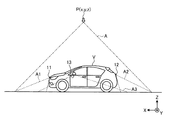
図2を用いて、前方カメラ11と後方カメラ12と左側方カメラ13と右側方カメラ14とについて説明する。図2は、第一実施形態に係る俯瞰映像生成システムにおける仮想視点の位置の一例を説明する概略図である。前方カメラ11は、車両Vの前方に配置され、車両Vの前方を中心とした周辺を撮影する。前方カメラ11は、例えば、180°程度の撮影範囲A1を撮影する。前方カメラ11は、撮影した映像を俯瞰映像生成装置40の映像データ取得部42へ出力する。
The
後方カメラ12は、車両Vの後方に配置され、車両Vの後方を中心とした周辺を撮影する。後方カメラ12は、例えば、180°程度の撮影範囲A2を撮影する。後方カメラ12は、撮影した映像を俯瞰映像生成装置40の映像データ取得部42へ出力する。
The
左側方カメラ13は、車両Vの左側方に配置され、車両Vの左側方を中心とした周辺を撮影する。左側方カメラ13は、例えば、180°程度の撮影範囲A3を撮影する。左側方カメラ13は、撮影した映像を俯瞰映像生成装置40の映像データ取得部42へ出力する。
The
右側方カメラ14は、車両Vの右側方に配置され、車両Vの右側方を中心とした周辺を撮影する。右側方カメラ14は、例えば、180°程度の図示しない撮影範囲A4を撮影する。右側方カメラ14は、撮影した映像を俯瞰映像生成装置40の映像データ取得部42へ出力する。
The right side camera 14 is arranged on the right side of the vehicle V and takes an image of the periphery around the right side of the vehicle V. The right camera 14 shoots a shooting range A4 (not shown) of about 180°, for example. The right camera 14 outputs the captured video to the video
このような前方カメラ11と後方カメラ12と左側方カメラ13と右側方カメラ14とで、車両Vの全方位を撮影する。
The
図1に戻って、センサ群20は、車両Vの周辺の障害物Qを検出する。センサ群20は、俯瞰映像の表示範囲を含む範囲の障害物Qを検出可能である。本実施形態では、センサ群20は、前方センサと、後方センサと、左側方センサと、右側方センサとを含む。センサ群20は、センシング方式によっては数十mから数百mの距離までのセンシングが可能であるが、本目的に用いる場合は車両Vから5m程度までの距離の障害物Qを検出する。センサ群20は、例えば、赤外線センサ、超音波センサ、ミリ波センサ、画像認識によるセンサ等、複数方式のセンサの組合せなど様々な方式が適用可能である。
Returning to FIG. 1, the
前方センサは、車両Vの前方に配置され、車両Vの前方を中心とした範囲に存在する障害物Qを検出する。前方センサは、車両Vが前進しているときに車両Vと接触するおそれがある、地上から高さを有するものを検出する。前方センサは、例えば、車両Vから5m程度までの距離の障害物Qを検出する。前方センサの検出範囲は、前方カメラ11の撮影範囲A1と重複する。前方センサの検出範囲は、左側方センサおよび右側方センサの検出範囲の一部と重複していてもよい。前方センサは、複数のセンサの組み合わせで構成されている。これにより、障害物Qの方向を細分化して検出する。前方センサは、検出した障害物Qの障害物情報を俯瞰映像生成装置40の障害物情報取得部43へ出力する。
The front sensor is arranged in front of the vehicle V and detects an obstacle Q existing in a range centered on the front of the vehicle V. The front sensor detects an object having a height from the ground that may come into contact with the vehicle V when the vehicle V is moving forward. The front sensor detects an obstacle Q at a distance of about 5 m from the vehicle V, for example. The detection range of the front sensor overlaps the shooting range A1 of the
後方センサは、車両Vの後方に配置され、車両Vの後方を中心とした範囲に存在する障害物Qを検出する。後方センサは、車両Vが後退しているときに車両Vと接触するおそれがある、地上から高さを有するものを検出する。後方センサは、例えば、車両Vから5m程度までの距離の障害物Qを検出する。後方センサの検出範囲は、後方カメラ12の撮影範囲A2と重複する。後方センサの検出範囲は、左側方センサおよび右側方センサの検出範囲の一部と重複していてもよい。後方センサは、複数のセンサの組み合わせで構成されている。これにより、障害物Qの方向を細分化して検出する。後方センサは、検出した障害物Qの障害物情報を俯瞰映像生成装置40の障害物情報取得部43へ出力する。
The rear sensor is arranged behind the vehicle V and detects an obstacle Q existing in a range centered on the rear of the vehicle V. The rear sensor detects an object having a height from the ground that may come into contact with the vehicle V when the vehicle V is moving backward. The rear sensor detects an obstacle Q at a distance of, for example, about 5 m from the vehicle V. The detection range of the rear sensor overlaps the shooting range A2 of the
左側方センサは、車両Vの左側方に配置され、車両Vの左側方を中心とした範囲に存在する障害物Qを検出する。左側方センサは、車両Vが操舵しながら前進または後退しているときに車両Vと接触するおそれがある、地上から高さを有するものを検出する。左側方センサは、例えば、車両Vから5m程度までの距離の障害物Qを検出する。左側方センサの検出範囲は、左側方カメラ13の撮影範囲A3と重複する。左側方センサの検出範囲は、前方センサおよび後方センサの検出範囲の一部と重複していてもよい。左側方センサは、複数のセンサの組み合わせで構成されている。これにより、障害物Qの方向を細分化して検出する。左側方センサは、検出した障害物Qの障害物情報を俯瞰映像生成装置40の障害物情報取得部43へ出力する。
The left side sensor is arranged on the left side of the vehicle V and detects an obstacle Q existing in a range centered on the left side of the vehicle V. The left side sensor detects an object having a height from the ground that may come into contact with the vehicle V when the vehicle V is moving forward or backward while steering. The left side sensor detects, for example, an obstacle Q at a distance of about 5 m from the vehicle V. The detection range of the left side sensor overlaps with the shooting range A3 of the
右側方センサは、車両Vの右側方に配置され、車両Vの右側方を中心とした範囲に存在する障害物Qを検出する。右側方センサは、車両Vが操舵しながら前進または後退しているときに車両Vと接触するおそれがある、地上から高さを有するものを検出する。右側方センサは、例えば、車両Vから5m程度までの距離の障害物Qを検出する。右側方センサの検出範囲は、右側方カメラ14の撮影範囲A4と重複する。右側方センサの検出範囲は、前方センサおよび後方センサの検出範囲の一部と重複していてもよい。右側方センサは、複数のセンサの組み合わせで構成されている。これにより、障害物Qの方向を細分化して検出する。右側方センサは、検出した障害物Qの障害物情報を俯瞰映像生成装置40の障害物情報取得部43へ出力する。
The right side sensor is arranged on the right side of the vehicle V and detects an obstacle Q existing in a range centered on the right side of the vehicle V. The right side sensor detects an object having a height from the ground that may come into contact with the vehicle V when the vehicle V is moving forward or backward while steering. The right side sensor detects an obstacle Q at a distance of about 5 m from the vehicle V, for example. The detection range of the right side sensor overlaps the shooting range A4 of the right side camera 14. The detection range of the right side sensor may overlap a part of the detection range of the front sensor and the rear sensor. The right side sensor is composed of a combination of a plurality of sensors. As a result, the direction of the obstacle Q is subdivided and detected. The right side sensor outputs the obstacle information of the detected obstacle Q to the obstacle
表示パネル30は、例えば、液晶ディスプレイ(LCD:Liquid Crystal Display)または有機EL(Organic Electro−Luminescence)ディスプレイを含むディスプレイである。表示パネル30は、俯瞰映像生成システム1の俯瞰映像生成装置40から出力された映像信号に基づいて、俯瞰映像100(図3参照)、俯瞰映像100A(図6参照)を表示する。表示パネル30は、俯瞰映像生成システム1に専用のものであっても、例えば、ナビゲーションシステムを含む他のシステムと共同で使用するものであってもよい。表示パネル30は、運転者から視認容易な位置に配置されている。
The
表示パネル30は、表示パネル30の形状が横長の矩形である場合、複数の表示範囲に分割されていてもよい。例えば、表示パネル30は、俯瞰映像100を表示する表示範囲と、俯瞰映像100の表示範囲の側方に配置された、ナビゲーション画面やオーディオ画面を表示する表示範囲とを有する。俯瞰映像100を表示する表示範囲は、縦長の矩形状である。
When the shape of the
俯瞰映像生成装置40は、制御部41と、記憶部49とを有する。
The overhead view video generation device 40 includes a control unit 41 and a
制御部41は、例えば、CPU(Central Processing Unit)などで構成された演算処理装置である。制御部41は、記憶部49に記憶されているプログラムをメモリにロードして、プログラムに含まれる命令を実行する。制御部41は、映像データ取得部42と、障害物情報取得部43と、車両情報取得部44と、俯瞰映像生成部45と、表示制御部48とを有する。
The control unit 41 is, for example, an arithmetic processing unit including a CPU (Central Processing Unit) and the like. The control unit 41 loads the program stored in the
映像データ取得部42は、車両Vの周辺を撮影した周辺映像データを取得する。より詳しくは、映像データ取得部42は、前方カメラ11と後方カメラ12と左側方カメラ13と右側方カメラ14とが出力した周辺映像データを取得する。映像データ取得部42は、取得した周辺映像データを俯瞰映像生成部45に出力する。
The video
障害物情報取得部43は、車両Vの周辺において検出した障害物Qの障害物情報を取得し、検出した障害物Qの俯瞰映像上の位置を特定する。より詳しくは、障害物情報取得部43は、センサ群20が出力した障害物情報を取得する。本実施形態では、障害物情報取得部43は、検出した障害物Qまでの距離を含む障害物情報を取得する。障害物情報取得部43は、取得した障害物情報に含まれる、障害物Qを検出したセンサと、障害物Qまでの距離とから、障害物Qの俯瞰映像上の位置を特定する。障害物情報取得部43は、取得した障害物情報と特定した障害物Qの位置とを俯瞰映像生成部45に出力する。
The obstacle
車両情報取得部44は、車両Vのギア操作情報など、俯瞰映像100を表示させるためのトリガとなる車両情報を、CAN(Controller Area Network)や車両Vの状態をセンシングする各種センサなどから取得する。本実施形態では、車両情報は、車両Vの進行方向を示す情報を含む。車両情報取得部44は、取得した車両情報を俯瞰映像生成部45に出力する。
The vehicle
俯瞰映像生成部45は、映像データ取得部42が取得した周辺映像データに視点変換処理を行い合成することで、車両Vの上方を仮想視点Pとした俯瞰映像100を生成する。
The bird's-eye view
図2を用いて、仮想視点Pについて説明する。仮想視点Pは、車両Vの中央の上方に位置している。仮想視点Pは、車両Vを真上から見下すような視点である。車両Vの中央とは、車両Vの車幅方向の中央、かつ、前後方向の中央である。車両Vの真上とは、車両Vの基準面の垂線上の位置である。基準面とは、車両Vが水平かつ平坦な路面上に位置しているときに路面と水平な平面である。仮想視点Pの位置を、(x,y,z)とする。 The virtual viewpoint P will be described with reference to FIG. The virtual viewpoint P is located above the center of the vehicle V. The virtual viewpoint P is a viewpoint that looks down on the vehicle V from directly above. The center of the vehicle V is the center of the vehicle V in the vehicle width direction and the center of the vehicle V in the front-rear direction. The position directly above the vehicle V is a position on the normal line of the reference plane of the vehicle V. The reference surface is a plane that is horizontal to the road surface when the vehicle V is located on a horizontal and flat road surface. The position of the virtual viewpoint P is (x, y, z).
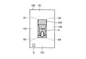
図3を用いて、生成された俯瞰映像100について説明する。図3は、第一実施形態に係る俯瞰映像生成システムで生成した俯瞰映像の一例を示す図である。俯瞰映像100は、前方映像101と後方映像102と左側方映像103と右側方映像104とを含む。前方映像101の表示面積と後方映像102の表示面積とは同じ広さである。左側方映像103の表示面積と右側方映像104の表示面積とは同じ広さである。俯瞰映像100の中央部は、車両Vを示す自車両アイコン200が表示されている。自車両アイコン200は、車両Vを真上から見下した形態を示す。
The generated bird's-
図3においては、前方映像101と左側方映像103との合成境界B1と、前方映像101と右側方映像104との合成境界B2と、後方映像102と左側方映像103との合成境界B3と、後方映像102と右側方映像104との合成境界B4とを示す斜めの破線を説明のために図示しているが、実際に表示パネル30に表示される俯瞰映像100には当該破線は表示されても表示されなくてもよい。他の図も同様である。以下の説明において、合成境界B1と合成境界B2と合成境界B3と合成境界B4とを特に区別する必要がないときは、合成境界Bとして説明する。
In FIG. 3, a combination boundary B1 between the
合成境界B1は、自車両アイコン200の左前端部から左前方に向かって延びている。合成境界B1は、自車両アイコン200の左前端部から長辺部100aへ延びている。合成境界B2は、自車両アイコン200の右前端部から右前方に向かって延びている。合成境界B2は、自車両アイコン200の右前端部から長辺部100bへ延びている。合成境界B3は、自車両アイコン200の左後端部から左後方に向かって延びている。合成境界B3は、自車両アイコン200の左後端部から長辺部100aへ延びている。合成境界B4は、自車両アイコン200の右後端部から右後方に向かって延びている。合成境界B4は、自車両アイコン200の右後端部から長辺部100bへ延びている。
The synthetic boundary B1 extends from the front left end of the
俯瞰映像生成部45は、障害物情報取得部43が特定した障害物Qの位置が、俯瞰映像100における複数の映像の境界である合成境界Bに重なる位置である場合、俯瞰映像100の仮想視点Pの位置を変更して仮想視点PAとした俯瞰映像100Aを生成する。言い換えると、俯瞰映像生成部45は、障害物Qの位置が、障害物Qを俯瞰映像100に表したときに合成境界Bに重なる位置である場合、仮想視点PAとした俯瞰映像100Aを生成する。さらに、俯瞰映像生成部45は、障害物Qの位置が、障害物Qを俯瞰映像100に表したときに合成境界Bの近傍に位置する場合にも、仮想視点PAとした俯瞰映像100Aを生成してもよい。
If the position of the obstacle Q identified by the obstacle
合成境界Bに重なる位置とは、複数の映像を合成したときに、画像処理によって被撮影物が非表示となったり歪んだりして、正しい形態が表示されなくなる範囲と重複する位置である。合成境界Bに重なる位置とは、例えば、合成境界Bを中心に帯状に広がる範囲に重なる位置である。 The position overlapping the combining boundary B is a position overlapping with a range in which the correct shape is not displayed due to the subject being hidden or distorted due to image processing when a plurality of images are combined. The position overlapping with the composite boundary B is, for example, a position overlapping with a range that spreads in a band shape around the composite boundary B.
合成境界Bの近傍の位置とは、合成境界Bに重なる位置より進行方向側の位置である。合成境界Bの近傍の位置とは、車両Vが進行することで合成境界Bに重なる位置となることが予測される位置である。 The position in the vicinity of the composite boundary B is a position on the traveling direction side of the position overlapping the composite boundary B. The position in the vicinity of the combined boundary B is a position predicted to be a position overlapping the combined boundary B as the vehicle V advances.
本実施形態では、俯瞰映像生成部45は、障害物情報取得部43が特定した障害物Qの位置が、俯瞰映像100における進行方向の合成境界B(以下、「進行方向の合成境界B」という。)に重なる場合、仮想視点Pの位置を車両Vの進行方向に応じた仮想視点PAに変更した俯瞰映像100Aを生成する。より詳しくは、俯瞰映像生成部45は、障害物Qの位置が進行方向の合成境界Bに重なるとき、仮想視点Pの位置を車両Vの進行方向側の仮想視点PAに変更した俯瞰映像100Aを生成する。仮想視点PAの位置は、(xA,y,z)で表される。
In the present embodiment, the bird's-eye view
例えば、車両Vが後退しているとき、俯瞰映像生成部45は、障害物Qの位置が合成境界B3または合成境界B4に重なるとき、仮想視点Pの位置を車両Vの後方側の仮想視点PAに変更した俯瞰映像100Aを生成する。
For example, when the vehicle V is moving backward, the bird's-eye view
例えば、車両Vが前進しているとき、俯瞰映像生成部45は、障害物Qの位置が合成境界B1または合成境界B2に重なるとき、仮想視点Pの位置を車両Vの前方側の仮想視点PAに変更した俯瞰映像100Aを生成する。
For example, when the vehicle V is moving forward, the bird's-eye view
俯瞰映像生成部45は、視点変換処理部451と、切出処理部452と、合成処理部453とを有する。
The bird's-eye view
視点変換処理部451は、映像データ取得部42で取得した周辺映像データに対して、車両Vを上方の仮想視点Pから見下ろすように視点変換処理を行う。より詳しくは、視点変換処理部451は、前方カメラ11と後方カメラ12と左側方カメラ13と右側方カメラ14とで撮影した周辺映像データに基づいて、視点変換処理を行った映像を生成する。視点変換処理の方法は、公知のいずれの方法でもよく、限定されない。視点変換処理部451は、視点変換処理を行った周辺映像データを切出処理部452に出力する。
The viewpoint
視点変換処理部451は、障害物情報取得部43が特定した障害物Qの位置が俯瞰映像100の合成境界Bに重なる位置である場合、俯瞰映像100の仮想視点Pの位置を変更した仮想視点PAとして視点変換処理を行った映像を生成する。視点変換処理部451は、視点変換処理を行った周辺映像データを切出処理部452に出力する。
The viewpoint
本実施形態では、視点変換処理部451は、仮想視点Pの位置を変更することで、複数のカメラの映像においてより表示範囲が広くなる映像に障害物Qが含まれて表示されるように、仮想視点Pの位置を変更する。
In the present embodiment, the viewpoint
本実施形態では、視点変換処理部451は、障害物情報取得部43が特定した障害物Qの位置が進行方向の合成境界Bに重なる場合、仮想視点Pの位置を車両Vの進行方向に応じた位置に変更して視点変換処理を行った映像を生成する。より詳しくは、視点変換処理部451は、障害物Qの位置が進行方向の合成境界Bに重なるとき、仮想視点Pの位置を車両Vの進行方向側に変更して視点変換処理を行った映像を生成する。
In the present embodiment, when the position of the obstacle Q specified by the obstacle
例えば、車両Vが後退しているとき、視点変換処理部451は、障害物Qの位置が合成境界B3または合成境界B4に重なるとき、仮想視点Pの位置を車両Vの後方側の仮想視点PAに変更して視点変換処理を行った映像を生成する。
For example, when the vehicle V is moving backward, the viewpoint
図4を用いて、仮想視点PAについて説明する。図4は、第一実施形態に係る俯瞰映像生成システムにおける仮想視点の位置の他の例を説明する概略図である。本実施形態では、仮想視点PAは、車両Vの後上方に位置している。仮想視点PAは、車両Vを後上から斜めに見下すような視点である。 The virtual viewpoint PA will be described with reference to FIG. FIG. 4 is a schematic diagram illustrating another example of the position of the virtual viewpoint in the overhead view image generation system according to the first embodiment. In this embodiment, the virtual viewpoint PA is located above and behind the vehicle V. The virtual viewpoint PA is a viewpoint that looks down the vehicle V obliquely from the upper rear.
例えば、車両Vが前進しているとき、視点変換処理部451は、障害物Qの位置が合成境界B1または合成境界B2に重なるとき、仮想視点Pの位置を車両Vの前方側の仮想視点PAに変更して視点変換処理を行った映像を生成する。
For example, when the vehicle V is moving forward, the viewpoint
切出処理部452は、視点変換処理を行った周辺映像データから所定の範囲の映像を切出す切出処理を行う。切出処理部452は、視点変換処理を行った前方カメラ11からの周辺映像データから、前方切出範囲を切出す。切出処理部452は、視点変換処理を行った後方カメラ12からの周辺映像データから、後方切出範囲を切出す。切出処理部452は、視点変換処理を行った左側方カメラ13からの周辺映像データから、左側方切出範囲を切出す。切出処理部452は、視点変換処理を行った右側方カメラ14からの周辺映像データから、右側方切出範囲を切出す。切出処理部452は、切出処理を行った映像の映像データを合成処理部453に出力する。
The
前方切出範囲は、車両Vの前端部から前方の範囲で、合成境界B1と合成境界B2とで囲まれた範囲である。後方切出範囲は、車両Vの後端部から後方の範囲で、合成境界B3と合成境界B4とで囲まれた範囲である。左側方切出範囲は、車両Vの左側部から左方の範囲で、合成境界B1と合成境界B3とで囲まれた範囲である。右側方切出範囲は、車両Vの右側部から右方の範囲で、合成境界B2と合成境界B4とで囲まれた範囲である。 The front cut-out range is a range from the front end of the vehicle V to the front, and is a range surrounded by the combined boundary B1 and the combined boundary B2. The rear cut-out range is a range behind the rear end of the vehicle V and is a range surrounded by the combined boundary B3 and the combined boundary B4. The left side cutout range is a range from the left side of the vehicle V to the left side, and is a range surrounded by the combined boundary B1 and the combined boundary B3. The right side cutout range is a range from the right side of the vehicle V to the right side, and is a range surrounded by the combined boundary B2 and the combined boundary B4.
仮想視点の位置ごとに俯瞰映像の合成境界Bの位置が一意に定義される。このため、前方切出範囲と後方切出範囲と左側方切出範囲と右側方切出範囲とは、切出処理を行った映像の仮想視点の位置に応じた合成境界Bの位置に基づいて定まる。仮想視点の位置ごとの俯瞰映像の合成境界Bの位置は、あらかじめ記憶部49に記憶されている。本実施形態では、仮想視点Pとした俯瞰映像100の合成境界Bの位置と、仮想視点PAとした俯瞰映像100Aの合成境界BAの位置とが記憶されている。
The position of the synthesis boundary B of the overhead view image is uniquely defined for each position of the virtual viewpoint. Therefore, the front cutout range, the rear cutout range, the left side cutout range, and the right side cutout range are based on the position of the composition boundary B according to the position of the virtual viewpoint of the image on which the cutout process is performed. Determined. The position of the synthesis boundary B of the overhead image for each position of the virtual viewpoint is stored in the
合成処理部453は、切出処理部452で切出した複数の映像を合成し俯瞰映像100、俯瞰映像100Aを生成する。合成処理部453は、生成した俯瞰映像100、俯瞰映像100Aを表示制御部48に出力する。
The combining
図5を用いて、生成された俯瞰映像100について説明する。図5は、第一実施形態に係る俯瞰映像生成システムで生成した俯瞰映像の他の例を示す図である。後方映像102には、障害物Qを示す障害物Qが表示されている。
The generated bird's-
図6を用いて、生成された俯瞰映像100Aについて説明する。図6は、第一実施形態に係る俯瞰映像生成システムで生成した俯瞰映像の他の例を示す図である。自車両アイコン210は、車両Vを後方から見下ろした形態を示している。自車両アイコン210は、自車両アイコン210による死角が生じないような表示形態とすることが好ましい。例えば、自車両アイコン210は、半透過としてもよい。例えば、自車両アイコン210は、外形を示す枠状としてもよい。前方映像101Aの表示面積は、前方映像101の表示面積に対して狭い。後方映像102Aの表示面積は、両側端部において、後方映像102の表示面積に対して前側に広い。後方映像102Aの表示面積は、前方映像101Aの表示面積に対して広い。左側方映像103Aの表示面積と右側方映像104Aの表示面積とは、左側方映像103の表示面積と右側方映像104の表示面積に対して前側に広い。
The generated bird's-
合成境界B1Aは、自車両アイコン210の左前端部から前方に向かって延びている。合成境界B1Aは、自車両アイコン210の左前端部から短辺部100Acへ延びている。合成境界B2Aは、自車両アイコン210の右前端部から前方に向かって延びている。合成境界B2Aは、自車両アイコン210の右前端部から短辺部100Acへ延びている。合成境界B3Aは、自車両アイコン210の左後端部から左方に向かって水平に延びている。合成境界B3Aは、自車両アイコン210の左後端部から長辺部100Aaへ延びている。合成境界B4Aは、自車両アイコン210の右後端部から右方に向かって水平に延びている。合成境界B4Aは、自車両アイコン210の右後端部から長辺部100Abへ延びている。
The synthetic boundary B1A extends forward from the left front end portion of the
合成境界B3Aと合成境界B4A近傍においては、左側方カメラ13と右側方カメラ14からの周辺映像データより、後方カメラ12からの周辺映像データの方が歪が少ない。このため、合成境界B3Aと合成境界B4Aとは、後方カメラ12からの周辺映像データの表示面積を広くするように設定されている。
In the vicinity of the composition boundary B3A and the composition boundary B4A, the peripheral image data from the
合成境界B1Aと合成境界B2A近傍においては、前方カメラ11からの周辺映像データより、左側方カメラ13と右側方カメラ14からの周辺映像データの方が歪が少ない。このため、合成境界B1Aと合成境界B2Aとは、左側方カメラ13と右側方カメラ14からの周辺映像データの表示面積を広くするように設定されている。
In the vicinity of the composition boundary B1A and the composition boundary B2A, the peripheral image data from the
図1に戻って、表示制御部48は、俯瞰映像100、俯瞰映像100Aを表示パネル30に表示させる。
Returning to FIG. 1, the
記憶部49は、俯瞰映像生成装置40における各種処理に要するデータおよび各種処理結果を記憶する。記憶部49は、例えば、RAM(Random Access Memory)、ROM(Read Only Memory)、フラッシュメモリ(Flash Memory)などの半導体メモリ素子、または、ハードディスク、光ディスクなどの記憶装置である。
The
次に、図7を用いて、俯瞰映像生成システム1の俯瞰映像生成装置40における処理の流れについて説明する。図7は、第一実施形態に係る俯瞰映像生成システムにおける処理の流れを示すフローチャートである。 Next, the flow of processing in the bird's-eye view video generation device 40 of the bird's-eye view video generation system 1 will be described with reference to FIG. 7. FIG. 7 is a flowchart showing the flow of processing in the overhead image generation system according to the first embodiment.
俯瞰映像生成システム1が起動されると、制御部41は、映像データ取得部42で周辺映像データを取得させる。制御部41は、障害物情報取得部43で障害物情報を取得させる。
When the bird's-eye view video generation system 1 is activated, the control unit 41 causes the video
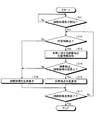
制御部41は、俯瞰映像表示を開始するか否かを判定する(ステップS11)。本実施形態では、制御部41は、後退トリガの有無に基づいて、俯瞰映像表示を開始するか否かを判定する。後退トリガとは、例えば、シフトポジションが「リバース」とされたことをいう。または、後退トリガとは、車両Vの進行方向が車両Vの後方となったことをいう。制御部41は、後退トリガがない場合、俯瞰映像表示を開始しないと判定し(ステップS11でNo)、ステップS11の処理を再度実行する。制御部41は、後退トリガがある場合、俯瞰映像表示を開始すると判定し(ステップS11でYes)、ステップS12に進む。俯瞰映像表示を開始させるトリガは、後退トリガに限らず、ユーザ操作、障害物検出結果、停止時など任意のトリガが適用される。 The control unit 41 determines whether or not to start the overhead view image display (step S11). In the present embodiment, the control unit 41 determines whether or not to start the bird's-eye view image display based on the presence/absence of the backward trigger. The backward trigger means that the shift position is set to "reverse", for example. Alternatively, the backward trigger means that the traveling direction of the vehicle V is behind the vehicle V. When there is no backward trigger, the control unit 41 determines not to start the bird's-eye view image display (No in step S11), and executes the process of step S11 again. When there is a backward trigger, the control unit 41 determines to start the bird's-eye view image display (Yes in step S11), and proceeds to step S12. The trigger for starting the overhead image display is not limited to the backward trigger, and any trigger such as user operation, obstacle detection result, and stop may be applied.
制御部41は、障害物Qを検出したか否かを判定する(ステップS12)。より詳しくは、制御部41は、障害物情報取得部43で、所定条件を満たす障害物Qの障害物情報が取得されたか否かを判定する。制御部41は、障害物情報取得部43で障害物情報が取得されたと判定した場合(ステップS12でYes)、ステップS13に進む。制御部41は、障害物情報取得部43で障害物情報が取得されていないと判定した場合(ステップS12でNo)、ステップS16に進む。
The control unit 41 determines whether or not the obstacle Q is detected (step S12). More specifically, the control unit 41 determines whether the obstacle
所定条件とは、障害物Qとして検出する条件である。本実施形態では、所定条件は、障害物Qが車両Vの進行方向に位置すること、である。障害物Qが車両Vの進行方向に位置する場合、所定条件を満たすと判定し、障害物Qとして検出する。例えば、車両Vが後退しているとき、障害物Qが車両Vの後端より後方に位置する場合、所定条件を満たすと判定し、障害物Qとして検出する。より詳しくは、制御部41は、車両Vが後退しているとき、センサ群20のうち、車両Vの後方の障害物Qを検出するセンサが障害物Qを検出した場合、所定条件を満たすと判定し、障害物Qとして検出する。
The predetermined condition is a condition for detecting the obstacle Q. In the present embodiment, the predetermined condition is that the obstacle Q is located in the traveling direction of the vehicle V. When the obstacle Q is located in the traveling direction of the vehicle V, it is determined that the predetermined condition is satisfied, and the obstacle Q is detected. For example, when the vehicle V is moving backward and the obstacle Q is located behind the rear end of the vehicle V, it is determined that the predetermined condition is satisfied, and the obstacle Q is detected. More specifically, when the vehicle V is moving backward, the control unit 41 satisfies the predetermined condition when the sensor of the
制御部41は、車両Vに対する障害物Qの位置情報を取得する(ステップS13)。より詳しくは、制御部41は、障害物情報取得部43で取得した障害物情報に基づいて、障害物Qの俯瞰映像上の位置を取得する。制御部41は、ステップS14に進む。
The control unit 41 acquires the position information of the obstacle Q with respect to the vehicle V (step S13). More specifically, the control unit 41 acquires the position of the obstacle Q on the bird's-eye view image based on the obstacle information acquired by the obstacle
制御部41は、障害物Qは俯瞰映像の合成境界B上に位置しているか否かを判定する(ステップS14)。より詳しくは、制御部41は、ステップS13で取得した障害物Qの位置情報に基づいて、障害物Qが進行方向の合成境界B上であるか否かを判定する。制御部41は、障害物Qが俯瞰映像100の合成境界Bに重なる位置であると判定した場合(ステップS14でYes)、ステップS15に進む。制御部41は、障害物Qが俯瞰映像100の合成境界Bに重なる位置ではないと判定した場合(ステップS14でNo)、ステップS16に進む。 The control unit 41 determines whether or not the obstacle Q is located on the synthesis boundary B of the overhead view image (step S14). More specifically, the control unit 41 determines whether or not the obstacle Q is on the combined boundary B in the traveling direction based on the position information of the obstacle Q acquired in step S13. When the control unit 41 determines that the obstacle Q is at the position overlapping the synthetic boundary B of the overhead view image 100 (Yes in step S14), the process proceeds to step S15. When the control unit 41 determines that the obstacle Q is not at the position overlapping the synthetic boundary B of the overhead view image 100 (No in step S14), the process proceeds to step S16.
制御部41は、仮想視点位置を変更する(ステップS15)。より詳しくは、制御部41は、俯瞰映像生成部45で、俯瞰映像100の仮想視点Pの位置を変更して仮想視点PAとした俯瞰映像100Aを生成させ、表示パネル30に表示させる。制御部41は、ステップS17に進む。
The control unit 41 changes the virtual viewpoint position (step S15). More specifically, the control unit 41 causes the bird's-eye view
本実施形態では、制御部41は、俯瞰映像生成部45で、仮想視点Pの位置を車両Vの進行方向に応じて、車両Vの進行方向側の仮想視点PAに変更した俯瞰映像100Aを生成させる。
In the present embodiment, the control unit 41 causes the overhead
制御部41は、俯瞰映像100を生成し表示する(ステップS16)。より詳しくは、制御部41は、俯瞰映像生成部45で、映像データ取得部42で取得した周辺映像データから車両Vを上方から見下ろすように視点変換処理を行い俯瞰映像100を生成させ、表示パネル30に表示させる。制御部41は、ステップS17に進む。
The control unit 41 generates and displays the overhead view image 100 (step S16). More specifically, the control unit 41 causes the bird's-eye view
制御部41は、俯瞰映像表示を終了するか否かを判定する(ステップS17)。より詳しくは、制御部41は、後退終了トリガの有無に基づいて、俯瞰映像表示を終了するか否かを判定する。後退終了トリガとは、例えば、シフトポジションが「リバース」から他のポジションとなったことをいう。制御部41は、後退終了トリガがある場合、俯瞰映像表示を終了すると判定し(ステップS17でYes)、処理を終了する。制御部41は、後退終了トリガがない場合、俯瞰映像表示を終了しないと判定し(ステップS17でNo)、ステップS12に戻って処理を継続する。 The control unit 41 determines whether or not to end the overhead view image display (step S17). More specifically, the control unit 41 determines whether to end the bird's-eye view image display based on the presence/absence of the backward movement end trigger. The reverse end trigger means, for example, that the shift position has changed from "reverse" to another position. When there is a backward movement end trigger, the control unit 41 determines to end the bird's-eye view image display (Yes in step S17), and ends the process. If there is no backward end trigger, the control unit 41 determines not to end the overhead view image display (No in step S17), and returns to step S12 to continue the process.
つづいて、図5、図6、図8、図9を用いて、車両Vが後方に進むとき、障害物Qが後方に検出された場合について説明する。図8は、第一実施形態に係る俯瞰映像生成システムで生成した俯瞰映像の他の例を示す図である。図9は、第一実施形態に係る俯瞰映像生成システムで生成した俯瞰映像の他の例を示す図である。障害物Qは、車両Vの後端部より左後方に位置している。 Next, a case where the obstacle Q is detected backward when the vehicle V moves backward will be described with reference to FIGS. 5, 6, 8, and 9. FIG. 8 is a diagram showing another example of the overhead view video generated by the overhead view video generation system according to the first embodiment. FIG. 9 is a diagram showing another example of the bird's-eye view video generated by the bird's-eye view video generation system according to the first embodiment. The obstacle Q is located to the left rear of the rear end of the vehicle V.
まず、シフトポジションが「リバース」とされると、ステップS11において、俯瞰映像表示を開始すると判定される。 First, when the shift position is set to "reverse", it is determined in step S11 to start the overhead image display.
ステップS12において、車両Vの後方に位置する障害物Qが検出される。ステップS13において、障害物Qの位置が車両Vの後端部より左後方であると取得される。ステップS14において、障害物Qは俯瞰映像100の合成境界B3上に位置していないと判定される。ステップS16において、図5に示すような、仮想視点Pとした俯瞰映像100が生成されて表示パネル30に表示される。ステップS17において、俯瞰映像表示終了ではないと判定されて、ステップS12に戻る。
In step S12, the obstacle Q located behind the vehicle V is detected. In step S13, the position of the obstacle Q is acquired as being left rear of the rear end portion of the vehicle V. In step S14, it is determined that the obstacle Q is not located on the synthetic boundary B3 of the
そして、ステップS12において、障害物Qが検出され、ステップS13において、車両Vに近づいた障害物Qの位置が取得される。ステップS14において、障害物Qは俯瞰映像100の合成境界B3上に位置していると判定される。ステップS15において、図6に示すような、仮想視点PAとした俯瞰映像100Aが生成されて表示パネル30に表示される。ステップS17において、俯瞰映像表示終了ではないと判定されて、ステップS12に戻る。
Then, in step S12, the obstacle Q is detected, and in step S13, the position of the obstacle Q approaching the vehicle V is acquired. In step S14, it is determined that the obstacle Q is located on the composite boundary B3 of the
図6に示す俯瞰映像100Aにおいては、障害物Qは、合成境界B3Aより後方に表示されている。
In the
そして、ステップS13において、障害物Qの位置が車両Vの後端部に近い左側方であると取得される。ステップS14において、障害物Qは俯瞰映像100の合成境界B3上に位置していないと判定される。ステップS16において、図8に示すような、仮想視点Pとした俯瞰映像100が生成されて表示パネル30に表示される。ステップS17において、俯瞰映像表示終了ではないと判定されて、ステップS12に戻る。
Then, in step S13, the position of the obstacle Q is acquired as being on the left side near the rear end of the vehicle V. In step S14, it is determined that the obstacle Q is not located on the synthetic boundary B3 of the
図8に示す俯瞰映像100においては、合成境界Bの位置は、図5に示す俯瞰映像100の合成境界Bと同じ位置である。障害物Qは、合成境界B3より前方に表示されている。
In the bird's-
そして、ステップS13において、障害物Qの位置が車両Vの後端部より左前方であると取得される。ステップS14において、障害物Qは俯瞰映像100の合成境界B3上に位置していないと判定される。ステップS16において、図9に示すような、仮想視点Pとした俯瞰映像100が生成されて表示パネル30に表示される。ステップS17において、俯瞰映像表示終了ではないと判定されて、ステップS12に戻る。
Then, in step S13, it is acquired that the position of the obstacle Q is to the left front of the rear end portion of the vehicle V. In step S14, it is determined that the obstacle Q is not located on the synthetic boundary B3 of the
図9に示す俯瞰映像100においては、合成境界Bの位置は、図5に示す俯瞰映像100の合成境界Bと同じ位置である。障害物Qは、合成境界B3よりさらに前方に表示されている。
In the bird's-
この後、車両Vがさらに後退すると、障害物Qが俯瞰映像100の合成境界B1を跨ぐ位置になるが、合成境界B1は進行方向ではないため、仮想視点の位置の変更処理は実行されない。
After that, when the vehicle V further moves backward, the obstacle Q reaches a position crossing the composite boundary B1 of the bird's-
このような処理が、俯瞰映像表示が終了されるまで繰り返される。 Such processing is repeated until the bird's-eye view image display is completed.
このようにして、俯瞰映像生成システム1は、障害物Qの位置が進行方向の合成境界Bに重なる場合、仮想視点Pの位置を車両Vの進行方向側の位置に変更した俯瞰映像100Aを生成する。
In this way, the overhead view image generation system 1 generates the
上述したように、本実施形態は、障害物Qの位置が進行方向の合成境界Bに重なる場合、仮想視点の位置を車両Vの進行方向に応じて、車両Vの進行方向側の位置に変更した仮想視点PAの俯瞰映像100Aを生成する。これにより、本実施形態は、障害物Qが進行方向の合成境界Bに重なる場合、仮想視点の位置をずらして、障害物Qが合成境界Bに重ならない俯瞰映像を表示することができる。これにより、障害物Qが合成境界B上に位置することで、障害物Qの形状が歪んだり、障害物Qが非表示となるようなことを抑制することができる。このように、本実施形態は、俯瞰映像において障害物Qを適切に表示することができる。本実施形態は、俯瞰映像における障害物Qの視認性を向上することができる。本実施形態は、車両周辺の障害物Qを適切に確認可能にすることができる。
As described above, in the present embodiment, when the position of the obstacle Q overlaps the synthetic boundary B in the traveling direction, the position of the virtual viewpoint is changed to the position on the traveling direction side of the vehicle V according to the traveling direction of the vehicle V. An
本実施形態は、俯瞰映像における障害物Qを検出した方向を表示する表示範囲が広くなるように、仮想視点の位置を変更して俯瞰映像を生成する。例えば、障害物Qが後方に検出された場合、障害物Qを検出した方向に対応する、俯瞰映像100Aの後方映像102Aの表示面積を、俯瞰映像100の後方映像102の表示面積に比べて広くする。これにより、本実施形態は、障害物Qとその周辺をより広い範囲で合成境界Bに重ならないようにした俯瞰映像100Aを表示することができる。このように、本実施形態は、俯瞰映像において障害物Qとその周辺を適切に表示することができる。本実施形態は、車両周辺の障害物Qとその周囲を適切に確認可能にすることができる。
In the present embodiment, the position of the virtual viewpoint is changed to generate the overhead view image so that the display range for displaying the direction in which the obstacle Q is detected in the overhead view image is widened. For example, when the obstacle Q is detected backward, the display area of the
しかも、本実施形態は、仮想視点の位置を車両Vの進行方向に応じて変更することで、障害物Qをより認識しやすい俯瞰映像を表示することができる。具体的には、本実施形態は、仮想視点Pの位置を車両Vの進行方向側の位置に変更した俯瞰映像100Aを生成する。これにより、本実施形態は、障害物Qを基準として、車両Vが近づいてくるような俯瞰映像100Aを表示することができる。言い換えると、本実施形態は、車両Vの進行方向に立って車両Vを誘導したような視点の俯瞰映像100Aを表示することができる。これにより、本実施形態は、障害物Qに対する車両Vの接近状態をより認識しやすい表示とすることができる。このように、本実施形態は、俯瞰映像において障害物Qを適切に表示することができる。
Moreover, in the present embodiment, by changing the position of the virtual viewpoint according to the traveling direction of the vehicle V, it is possible to display the overhead view image in which the obstacle Q can be more easily recognized. Specifically, the present embodiment generates the
本実施形態は、障害物Qの位置が進行方向の合成境界Bに重なる場合、仮想視点PAの俯瞰映像100Aを生成表示する。そして、本実施形態は、障害物Qの位置が進行方向の合成境界Bに重なる位置から外れた場合、仮想視点Pの俯瞰映像100を生成表示する。このように、本実施形態は、障害物Qの位置が進行方向の合成境界Bに重なる間だけ、仮想視点PAの俯瞰映像100Aを生成表示する。このため、本実施形態は、仮想視点の位置が頻繁に変更されることがなく、俯瞰映像の表示が煩雑になることを抑制することができる。
In the present embodiment, when the position of the obstacle Q overlaps the synthetic boundary B in the traveling direction, the bird's-
本実施形態は、仮想視点の位置が変更されると、自車両アイコンが変化する。これにより、運転者は、仮想視点の位置が変更されていることを容易に認識することができる。 In this embodiment, when the position of the virtual viewpoint is changed, the vehicle icon changes. This allows the driver to easily recognize that the position of the virtual viewpoint has been changed.
[第二実施形態]
図10を参照しながら、本実施形態に係る俯瞰映像生成システム1について説明する。図10は、第二実施形態に係る俯瞰映像生成システムで生成した俯瞰映像の一例を示す図である。俯瞰映像生成システム1は、基本的な構成は第一実施形態の俯瞰映像生成システム1と同様である。以下の説明においては、俯瞰映像生成システム1と同様の構成要素には、同一の符号または対応する符号を付し、その詳細な説明は省略する。本実施形態の俯瞰映像生成システム1は、俯瞰映像生成部45における処理が、第一実施形態の俯瞰映像生成システム1と異なる。
[Second embodiment]
The overhead view image generation system 1 according to the present embodiment will be described with reference to FIG. 10. FIG. 10 is a diagram showing an example of a bird's-eye view image generated by the bird's-eye view image generation system according to the second embodiment. The bird's-eye view video generation system 1 has the same basic configuration as the bird's-eye view video generation system 1 of the first embodiment. In the following description, the same components as those of the bird's-eye view video generation system 1 are designated by the same or corresponding symbols, and detailed description thereof is omitted. The bird's-eye view video generation system 1 of this embodiment is different from the bird's-eye view video generation system 1 of the first embodiment in the processing in the bird's-eye view
俯瞰映像生成部45は、障害物情報取得部43が特定した障害物Qの位置が進行方向の合成境界Bに重なるとき、仮想視点Pの位置を車両Vの進行方向とは反対側の仮想視点PBに変更した俯瞰映像100Bを生成する。仮想視点PBの位置は、(xB,y,z)で表される。
When the position of the obstacle Q identified by the obstacle
例えば、車両Vが後退しているとき、俯瞰映像生成部45は、障害物Qの位置が合成境界B3または合成境界B4に重なるとき、仮想視点Pの位置を車両Vの前方側の仮想視点PBに変更した俯瞰映像100Bを生成する。
For example, when the vehicle V is moving backward, the bird's-eye view
例えば、車両Vが前進しているとき、俯瞰映像生成部45は、障害物Qの位置が合成境界B1または合成境界B2に重なるとき、仮想視点Pの位置を車両Vの後方側の仮想視点PBに変更した俯瞰映像100Bを生成する。
For example, when the vehicle V is moving forward, when the position of the obstacle Q overlaps the composite boundary B1 or the composite boundary B2, the overhead view
視点変換処理部451は、障害物Qの位置が進行方向の合成境界Bに重なるとき、仮想視点Pの位置を車両Vの進行方向とは反対側に変更して視点変換処理を行った映像を生成する。
The viewpoint
例えば、車両Vが後退しているとき、視点変換処理部451は、障害物Qの位置が合成境界B3または合成境界B4に重なるとき、仮想視点Pの位置を車両Vの前方側の仮想視点PBに変更して視点変換処理を行った映像を生成する。
For example, when the vehicle V is moving backward, the viewpoint
例えば、車両Vが前進しているとき、視点変換処理部451は、障害物Qの位置が合成境界B1または合成境界B2に重なるとき、仮想視点Pの位置を車両Vの後方側の仮想視点PBに変更して視点変換処理を行った映像を生成する。
For example, when the vehicle V is moving forward, the viewpoint
次に、俯瞰映像生成システム1の俯瞰映像生成装置40における処理の流れについて説明する。俯瞰映像生成装置40は、図7に示すフローチャートに沿った処理を行う。本実施形態は、ステップS15における処理が第一実施形態と異なり、ステップS11〜ステップS14、ステップS16、ステップS17の処理は第一実施形態と同様の処理を行う。 Next, the flow of processing in the bird's-eye view video generation device 40 of the bird's-eye view video generation system 1 will be described. The bird's-eye view video generation device 40 performs processing according to the flowchart shown in FIG. 7. In this embodiment, the processing in step S15 is different from that in the first embodiment, and the processing in steps S11 to S14, step S16, and step S17 is the same as that in the first embodiment.
制御部41は、仮想視点位置を変更する(ステップS15)。より詳しくは、制御部41は、俯瞰映像生成部45で、俯瞰映像100の仮想視点Pの位置を車両Vの進行方向とは反対側に変更して仮想視点PBとした俯瞰映像100Bを生成させ、表示パネル30に表示させる。制御部41は、ステップS17に進む。
The control unit 41 changes the virtual viewpoint position (step S15). More specifically, the control unit 41 causes the bird's-eye view
図10を用いて、第一実施形態と同様に、車両Vが後方に進むとき、障害物Qが後方に検出された場合について説明する。 Similar to the first embodiment, a case where the obstacle Q is detected backward when the vehicle V moves backward will be described with reference to FIG. 10.
まず、シフトポジションが「リバース」とされると、ステップS11において、俯瞰映像表示を開始すると判定される。 First, when the shift position is set to "reverse", it is determined in step S11 to start the overhead image display.
ステップS12において、車両Vの後方に位置する障害物Qが検出される。ステップS13において、障害物Qの位置が車両Vの後端部より左後方であると取得される。ステップS14において、障害物Qは俯瞰映像100の合成境界B3上に位置していないと判定される。ステップS16において、図5に示すような、仮想視点Pとした俯瞰映像100が生成されて表示パネル30に表示される。ステップS17において、俯瞰映像表示終了ではないと判定されて、ステップS12に戻る。
In step S12, the obstacle Q located behind the vehicle V is detected. In step S13, the position of the obstacle Q is acquired as being left rear of the rear end portion of the vehicle V. In step S14, it is determined that the obstacle Q is not located on the synthetic boundary B3 of the
そして、ステップS12において、障害物Qが検出され、ステップS13において、車両Vに近づいた障害物Qの位置が取得される。ステップS14において、障害物Qは俯瞰映像100の合成境界B3上に位置していると判定される。ステップS15において、図10に示すような、仮想視点PBとした俯瞰映像100Bが生成されて表示パネル30に表示される。ステップS17において、俯瞰映像表示終了ではないと判定されて、ステップS12に戻る。
Then, in step S12, the obstacle Q is detected, and in step S13, the position of the obstacle Q approaching the vehicle V is acquired. In step S14, it is determined that the obstacle Q is located on the composite boundary B3 of the
図10を用いて、生成された俯瞰映像100Bについて説明する。自車両アイコン220は、車両Vを前方から見下ろした形態を示している。障害物Qは、合成境界B3Bより前方に表示されている。
The generated bird's-
前方映像101Bの表示面積は、両側端部において、前方映像101の表示面積に対して後側に広い。前方映像101Bの表示面積は、後方映像102Bの表示面積に対して広い。後方映像102Bの表示面積は、後方映像102の表示面積に対して狭い。左側方映像103Bの表示面積と右側方映像104Bの表示面積とは、左側方映像103の表示面積と右側方映像104の表示面積に対して後側に広い。
The display area of the
合成境界B1Bは、自車両アイコン220の左前端部から左方に向かって水平に延びている。合成境界B1Bは、自車両アイコン220の左前端部から長辺部100Baへ延びている。合成境界B2Bは、自車両アイコン220の右前端部から右方に向かって水平に延びている。合成境界B2Bは、自車両アイコン220の右前端部から長辺部100Bbへ延びている。合成境界B3Bは、自車両アイコン220の左後端部から後方に向かって延びている。合成境界B3Bは、自車両アイコン220の左後端部から短辺部100Bdへ延びている。合成境界B4Bは、自車両アイコン220の右後端部から後方に向かって延びている。合成境界B4Bは、自車両アイコン220の右後端部から短辺部100Bdへ延びている。
The combined boundary B1B extends horizontally from the front left end of the
合成境界B3Bと合成境界B4B近傍においては、後方カメラ12からの周辺映像データより、左側方カメラ13と右側方カメラ14からの周辺映像データの方が歪が少ない。このため、合成境界B3Bと合成境界B4Bとは、左側方カメラ13と右側方カメラ14からの周辺映像データの表示面積を広くするように設定されている。
In the vicinity of the composition boundary B3B and the composition boundary B4B, the peripheral video data from the
合成境界B1Bと合成境界B2B近傍においては、左側方カメラ13と右側方カメラ14からの周辺映像データより、前方カメラ11からの周辺映像データの方が歪が少ない。このため、合成境界B1Bと合成境界B2Bとは、左側方カメラ13と右側方カメラ14からの周辺映像データの表示面積を広くするように設定されている。
In the vicinity of the composition boundary B1B and the composition boundary B2B, the peripheral video data from the
そして、ステップS13において、障害物Qの位置が車両Vの後端部に近い左側方であると取得される。ステップS14において、障害物Qは俯瞰映像100の合成境界B3上に位置していないと判定される。ステップS16において、図8に示すような、仮想視点Pとした俯瞰映像100が生成されて表示パネル30に表示される。ステップS17において、俯瞰映像表示終了ではないと判定されて、ステップS12に戻る。
Then, in step S13, the position of the obstacle Q is acquired as being on the left side near the rear end of the vehicle V. In step S14, it is determined that the obstacle Q is not located on the synthetic boundary B3 of the
そして、ステップS13において、障害物Qの位置が車両Vの後端部より左前方であると取得される。ステップS14において、障害物Qは俯瞰映像100の合成境界B3上に位置していないと判定される。ステップS16において、図9に示すような、仮想視点Pとした俯瞰映像100が生成されて表示パネル30に表示される。ステップS17において、俯瞰映像表示終了ではないと判定されて、ステップS12に戻る。
Then, in step S13, it is acquired that the position of the obstacle Q is to the left front of the rear end portion of the vehicle V. In step S14, it is determined that the obstacle Q is not located on the synthetic boundary B3 of the
このような処理が、俯瞰映像表示が終了されるまで繰り返される。 Such processing is repeated until the bird's-eye view image display is completed.
上述したように、本実施形態は、障害物Qの位置が進行方向の合成境界Bに重なる場合、車両Vの進行方向と反対側に位置を変更した仮想視点PBの俯瞰映像100Bを生成する。これにより、本実施形態は、障害物Qが進行方向の合成境界Bに重なる場合、仮想視点の位置をずらして、障害物Qが合成境界Bに重ならない俯瞰映像を表示することができる。これにより、障害物Qが合成境界B上に位置することで、障害物Qの形状が歪んだり、障害物Qが非表示となるようなことを抑制することができる。このように、本実施形態は、俯瞰映像において障害物Qを適切に表示することができる。本実施形態は、俯瞰映像における障害物Qの視認性を向上することができる。本実施形態は、車両周辺の障害物Qを適切に確認可能にすることができる。
As described above, when the position of the obstacle Q overlaps the composite boundary B in the traveling direction, the present embodiment generates the bird's-
しかも、本実施形態は、仮想視点Pの位置を車両Vの進行方向と反対側に変更した俯瞰映像100Bを生成する。これにより、本実施形態は、車両Vの進行方向と反対側に立って車両Vを誘導したような視点の俯瞰映像100Bを表示することができる。これにより、本実施形態は、障害物Qに対する車両Vの接近状態をより認識しやすい表示とすることができる。このように、本実施形態は、俯瞰映像において障害物Qを適切に表示することができる。
Moreover, the present embodiment generates the bird's-
[第三実施形態]
図11を参照しながら、本実施形態に係る俯瞰映像生成システム1について説明する。図11は、第三実施形態に係る俯瞰映像生成システムで生成した俯瞰映像の一例を示す図である。本実施形態の俯瞰映像生成システム1は、俯瞰映像生成部45における処理が、第一実施形態の俯瞰映像生成システム1と異なる。
[Third embodiment]
The overhead view image generation system 1 according to the present embodiment will be described with reference to FIG. 11. FIG. 11 is a diagram showing an example of a bird's-eye view image generated by the bird's-eye view image generation system according to the third embodiment. The bird's-eye view video generation system 1 of this embodiment is different from the bird's-eye view video generation system 1 of the first embodiment in the processing in the bird's-eye view
俯瞰映像生成部45は、障害物情報取得部43が特定した障害物Qの位置が進行方向の合成境界Bに重なるとき、仮想視点Pの位置を車両Vの進行方向と交差する方向、例えば、側方に変更した俯瞰映像100Cを生成する。
When the position of the obstacle Q specified by the obstacle
例えば、車両Vが後退しているとき、俯瞰映像生成部45は、障害物Qの位置が合成境界B3または合成境界B4に重なるとき、仮想視点Pの位置を車両Vの左側または右側の仮想視点PCに変更した俯瞰映像100Cを生成する。仮想視点PCは、障害物Qが検出された側とすることが好ましい。仮想視点PCの位置は、(x,yC,z)で表される。
For example, when the vehicle V is moving backward, the bird's-eye view
例えば、車両Vが前進しているとき、俯瞰映像生成部45は、障害物Qの位置が合成境界B1または合成境界B2に重なるとき、仮想視点Pの位置を車両Vの左側または右側の仮想視点PCに変更した俯瞰映像100Cを生成する。
For example, when the vehicle V is moving forward, when the position of the obstacle Q overlaps the composite boundary B1 or the composite boundary B2, the overhead view
視点変換処理部451は、障害物Qの位置が進行方向の合成境界Bに重なるとき、仮想視点Pの位置を車両Vの進行方向と交差する方向に変更して視点変換処理を行った映像を生成する。
The viewpoint
例えば、車両Vが後退しているとき、視点変換処理部451は、障害物Qの位置が合成境界B3または合成境界B4に重なるとき、仮想視点Pの位置を車両Vの左側または右側の仮想視点PCに変更して視点変換処理を行った映像を生成する。
For example, when the vehicle V is moving backward, the viewpoint
例えば、車両Vが前進しているとき、視点変換処理部451は、障害物Qの位置が合成境界B1または合成境界B2に重なるとき、仮想視点Pの位置を車両Vの左側または右側の仮想視点PCに変更して視点変換処理を行った映像を生成する。
For example, when the vehicle V is moving forward, the viewpoint
次に、俯瞰映像生成システム1の俯瞰映像生成装置40における処理の流れについて説明する。俯瞰映像生成装置40は、図7に示すフローチャートに沿った処理を行う。本実施形態は、ステップS15における処理が第一実施形態と異なり、ステップS11〜ステップS14、ステップS16、ステップS17の処理は第一実施形態と同様の処理を行う。 Next, the flow of processing in the bird's-eye view video generation device 40 of the bird's-eye view video generation system 1 will be described. The bird's-eye view video generation device 40 performs processing according to the flowchart shown in FIG. 7. In this embodiment, the processing in step S15 is different from that in the first embodiment, and the processing in steps S11 to S14, step S16, and step S17 is the same as that in the first embodiment.
制御部41は、仮想視点位置を変更する(ステップS15)。より詳しくは、制御部41は、俯瞰映像生成部45で、俯瞰映像100の仮想視点Pの位置を車両Vの進行方向と交差する方向に変更して仮想視点PCとした俯瞰映像100Cを生成させ、表示パネル30に表示させる。制御部41は、ステップS17に進む。
The control unit 41 changes the virtual viewpoint position (step S15). More specifically, the control unit 41 causes the bird's-eye view
図11を用いて、第一実施形態と同様に、車両Vが後方に進むとき、障害物Qが後方に検出された場合について説明する。 Similar to the first embodiment, a case where the obstacle Q is detected backward when the vehicle V moves backward will be described with reference to FIG. 11.
まず、シフトポジションが「リバース」とされると、ステップS11において、俯瞰映像表示を開始すると判定される。 First, when the shift position is set to "reverse", it is determined in step S11 to start the overhead image display.
ステップS12において、車両Vの後方に位置する障害物Qが検出される。ステップS13において、障害物Qの位置が車両Vの後端部より左後方であると取得される。ステップS14において、障害物Qは俯瞰映像100の合成境界B3上に位置していないと判定される。ステップS16において、図5に示すような、仮想視点Pとした俯瞰映像100が生成されて表示パネル30に表示される。ステップS17において、俯瞰映像表示終了ではないと判定されて、ステップS12に戻る。
In step S12, the obstacle Q located behind the vehicle V is detected. In step S13, the position of the obstacle Q is acquired as being left rear of the rear end portion of the vehicle V. In step S14, it is determined that the obstacle Q is not located on the synthetic boundary B3 of the
そして、ステップS12において、障害物Qが検出され、ステップS13において、車両Vに近づいた障害物Qの位置が取得される。ステップS14において、障害物Qは俯瞰映像100の合成境界B3上に位置していると判定される。ステップS15において、図11に示すような、仮想視点PCとした俯瞰映像100Cが生成されて表示パネル30に表示される。ステップS17において、俯瞰映像表示終了ではないと判定されて、ステップS12に戻る。
Then, in step S12, the obstacle Q is detected, and in step S13, the position of the obstacle Q approaching the vehicle V is acquired. In step S14, it is determined that the obstacle Q is located on the composite boundary B3 of the
図11を用いて、生成された俯瞰映像100Cについて説明する。自車両アイコン230は、車両Vを左側方から見下ろした形態を示している。障害物Qは、合成境界B3Cより前方に表示されている。
The generated bird's-
前方映像101Cの表示面積と後方映像102Cの表示面積とは、前側方映像101の表示面積と後側方映像102の表示面積とに対して狭い。左側方映像103Cの表示面積は、左側方映像103の表示面積に対して前後方向に広い。左側方映像103Cの表示面積は、右側方映像104Cの表示面積に対して広い。右側方映像104Cの表示面積は、右側方映像104の表示面積と同じである。
The display area of the
合成境界B1Cは、自車両アイコン230の左前端部から前方に向かって延びている。合成境界B1Cは、自車両アイコン230の左前端部から短辺部100Ccへ延びている。合成境界B2Cは、自車両アイコン230の右前端部から右方に向かって延びている。合成境界B2Cは、自車両アイコン230の右前端部から長辺部100Cbへ延びている。合成境界B3Cは、自車両アイコン230の左後端部から後方に向かって延びている。合成境界B3Cは、自車両アイコン230の左後端部から短辺部100Cdへ延びている。合成境界B4Cは、自車両アイコン230の右後端部から右方に向かって延びている。合成境界B4Cは、自車両アイコン230の右後端部から長辺部100Cbへ延びている。
The synthetic boundary B1C extends forward from the left front end portion of the
合成境界B3C近傍においては、後方カメラ12からの周辺映像データより、左側方カメラ13からの周辺映像データの方が歪が少ない。このため、合成境界B3Cは、左側方カメラ13からの周辺映像データの表示面積を広くするように設定されている。
In the vicinity of the synthesis boundary B3C, the peripheral image data from the
合成境界B1C近傍においては、前方カメラ11からの周辺映像データより、左側方カメラ13からの周辺映像データの方が歪が少ない。このため、合成境界B1Cは、左側方カメラ13からの周辺映像データの表示面積を広くするように設定されている。
In the vicinity of the synthesis boundary B1C, the peripheral image data from the
そして、ステップS13において、障害物Qの位置が車両Vの後端部に近い左側方であると取得される。ステップS14において、障害物Qは俯瞰映像100における合成境界B3上に位置していないと判定される。ステップS16において、図8に示すような、仮想視点Pとした俯瞰映像100が生成されて表示パネル30に表示される。ステップS17において、俯瞰映像表示終了ではないと判定されて、ステップS12に戻る。
Then, in step S13, the position of the obstacle Q is acquired as being on the left side near the rear end of the vehicle V. In step S14, it is determined that the obstacle Q is not located on the composite boundary B3 in the
そして、ステップS13において、障害物Qの位置が車両Vの後端部より左前方であると取得される。ステップS14において、障害物Qは俯瞰映像100Cにおける合成境界B3上に位置していないと判定される。ステップS16において、図9に示すような、仮想視点Pとした俯瞰映像100が生成されて表示パネル30に表示される。ステップS17において、俯瞰映像表示終了ではないと判定されて、ステップS12に戻る。
Then, in step S13, it is acquired that the position of the obstacle Q is to the left front of the rear end portion of the vehicle V. In step S14, it is determined that the obstacle Q is not located on the synthesis boundary B3 in the
このような処理が、俯瞰映像表示が終了されるまで繰り返される。 Such processing is repeated until the bird's-eye view image display is completed.
上述したように、本実施形態は、障害物Qの位置が進行方向の合成境界Bに重なる場合、車両Vの進行方向と交差する方向に位置を変更した仮想視点PCの俯瞰映像100Cを生成する。これにより、本実施形態は、障害物Qが進行方向の合成境界Bに重なる場合、仮想視点の位置をずらして、障害物Qが合成境界Bに重ならない俯瞰映像を表示することができる。これにより、障害物Qが合成境界B上に位置することで、障害物Qの形状が歪んだり、障害物Qが非表示となるようなことを抑制することができる。このように、本実施形態は、俯瞰映像において障害物Qを適切に表示することができる。本実施形態は、俯瞰映像における障害物Qの視認性を向上することができる。本実施形態は、車両周辺の障害物Qを適切に確認可能にすることができる。
As described above, in the present embodiment, when the position of the obstacle Q overlaps the synthetic boundary B in the traveling direction, the bird's-
しかも、本実施形態は、仮想視点Pの位置を車両Vの進行方向と交差する方向に変更した俯瞰映像100Cを生成する。これにより、本実施形態は、車両の側方に立って車両Vを誘導するような仮想視点PCの俯瞰映像100Cを表示することができる。これにより、本実施形態は、障害物Qに対する車両Vの接近状態をより認識しやすい表示とすることができる。このように、本実施形態によれば、運転者は、車両周辺の障害物Qを適切に確認することができる。
Moreover, the present embodiment generates the bird's-
[第四実施形態]
図12ないし図15を参照しながら、本実施形態に係る俯瞰映像生成システム1について説明する。図12は、第四実施形態に係る俯瞰映像生成システムの俯瞰映像生成装置における処理の流れを示すフローチャートである。図13は、第四実施形態に係る俯瞰映像生成システムで生成した俯瞰映像の一例を示す図である。図14は、第四実施形態に係る俯瞰映像生成システムで生成した俯瞰映像の他の例を示す図である。図15は、第四実施形態に係る俯瞰映像生成システムで生成した俯瞰映像の他の例を示す図である。本実施形態の俯瞰映像生成システム1は、俯瞰映像生成部45における処理が、第二実施形態の俯瞰映像生成システム1と異なる。本実施形態では、複数の障害物Q1、障害物Q2が検出された場合に対応している。
[Fourth Embodiment]
The overhead view image generation system 1 according to the present embodiment will be described with reference to FIGS. 12 to 15. FIG. 12 is a flowchart showing the flow of processing in the bird's-eye view video generation device of the bird's-eye view video generation system according to the fourth embodiment. FIG. 13 is a diagram showing an example of a bird's-eye view image generated by the bird's-eye view image generation system according to the fourth embodiment. FIG. 14 is a diagram showing another example of the overhead view video generated by the overhead view video generation system according to the fourth embodiment. FIG. 15 is a diagram showing another example of the overhead view video generated by the overhead view video generation system according to the fourth embodiment. The bird's-eye view video generation system 1 of this embodiment is different from the bird's-eye view video generation system 1 of the second embodiment in the processing in the bird's-eye view
俯瞰映像生成システム1の俯瞰映像生成装置40における処理の流れについて説明する。ステップS21、S26、S27の処理は、第一実施形態のステップS11、S16、ステップS17と同様の処理を行う。 The flow of processing in the overhead view video generation device 40 of the overhead view video generation system 1 will be described. The processes of steps S21, S26, and S27 are the same as steps S11, S16, and S17 of the first embodiment.
制御部41は、障害物Qを検出したか否かを判定する(ステップS22)。より詳しくは、制御部41は、障害物情報取得部43で、所定条件を満たす障害物Qの障害物情報が取得されたか否かを判定する。本実施形態では、複数の障害物Qが所定条件を満たすものとする。制御部41は、障害物Qを検出したと判定した場合(ステップS22でYes)、ステップS23に進む。制御部41は、障害物Qを検出していないと判定した場合(ステップS22でNo)、ステップS26に進む。
The control unit 41 determines whether or not the obstacle Q is detected (step S22). More specifically, the control unit 41 determines whether the obstacle
制御部41は、障害物Qの位置情報を取得する(ステップS23)。より詳しくは、制御部41は、障害物情報取得部43で取得した障害物情報に基づいて、すべての障害物Qの俯瞰映像上における位置を取得する。制御部41は、ステップS24に進む。
The control unit 41 acquires the position information of the obstacle Q (step S23). More specifically, the control unit 41 acquires the positions of all the obstacles Q on the bird's-eye view image based on the obstacle information acquired by the obstacle
制御部41は、俯瞰映像の合成境界B上に位置している障害物Qがあるか否かを判定する(ステップS24)。より詳しくは、制御部41は、ステップS23で取得した障害物Qの位置情報について、俯瞰映像100において、進行方向の合成境界Bに重なる位置の障害物Qがあるか否かを判定する。制御部41は、進行方向の合成境界Bに重なる位置の障害物Qに加えて、進行方向の合成境界Bに重なることが予測される位置の障害物Qがあるか否かを判定する。進行方向の合成境界Bに重なることが予測される位置の障害物Qとは、車両Vが進行方向に移動することで、合成境界Bに重なることが予測される位置の障害物Qのことである。これにより、仮想視点の位置を変更する回数を抑制する。
The control unit 41 determines whether or not there is an obstacle Q located on the synthesis boundary B of the overhead view image (step S24). More specifically, the control unit 41 determines whether or not there is an obstacle Q at a position overlapping the composite boundary B in the traveling direction in the
制御部41は、俯瞰映像100の合成境界Bに重なる位置の障害物Qがあると判定した場合(ステップS24でYes)、ステップS25に進む。制御部41は、俯瞰映像100の合成境界Bに重なる位置の障害物Qがないと判定した場合(ステップS24でNo)、ステップS26に進む。 When the control unit 41 determines that there is an obstacle Q at a position overlapping the synthesis boundary B of the bird's-eye view image 100 (Yes in step S24), the process proceeds to step S25. When the control unit 41 determines that there is no obstacle Q at a position overlapping the synthesis boundary B of the overhead view image 100 (No in step S24), the process proceeds to step S26.
制御部41は、仮想視点位置を変更する(ステップS25)。より詳しくは、制御部41は、俯瞰映像生成部45で、俯瞰映像100の仮想視点Pの位置を変更して仮想視点PAとした俯瞰映像100Aを生成させ、表示パネル30に表示させる。制御部41は、ステップS27に進む。
The control unit 41 changes the virtual viewpoint position (step S25). More specifically, the control unit 41 causes the bird's-eye view
図13ないし図15を用いて、車両Vが後方に進むとき、二つの障害物Q1、障害物Q2が後方に検出された場合について説明する。複数の障害物Q1、障害物Q2は、車両Vの後端部より左後方に位置しているものとする。 A case where two obstacles Q1 and Q2 are detected backward when the vehicle V travels backward will be described with reference to FIGS. 13 to 15. It is assumed that the plurality of obstacles Q1 and Q2 are located to the left rear of the rear end portion of the vehicle V.
まず、シフトポジションが「リバース」とされると、ステップS21において、俯瞰映像表示を開始すると判定される。 First, when the shift position is set to "reverse", it is determined in step S21 that the overhead view image display is started.
そして、ステップS22において、車両Vの後方に位置する二つの障害物Q1、障害物Q2が検出される。ステップS23において、障害物Q1の位置が俯瞰映像における合成境界B3上の位置であると取得される。ステップS24において、障害物Q1は俯瞰映像100の合成境界B3上に位置していると判定される。ステップS25において、図13に示すような、仮想視点PAとした俯瞰映像100Aが生成されて表示パネル30に表示される。ステップS27において、俯瞰映像表示終了ではないと判定されて、ステップS22に戻る。
Then, in step S22, two obstacles Q1 and Q2 located behind the vehicle V are detected. In step S23, the position of the obstacle Q1 is acquired as the position on the synthesis boundary B3 in the overhead view image. In step S24, it is determined that the obstacle Q1 is located on the composite boundary B3 of the
図13に示す俯瞰映像100Aにおいては、合成境界Bの位置は、図6に示す俯瞰映像100Aの合成境界Bと同じ位置である。障害物Q1、障害物Q2は、合成境界B3Aより後方に位置している。
In the
そして、ステップS22において、障害物Q1およびQ2が検出されステップS23において、障害物Q1の位置は俯瞰映像における合成境界B3上の位置ではないと取得される。また、障害物Q2の位置は、俯瞰映像における合成境界B3上の位置ではないが、車両Vが進行方向に移動すると、合成境界B3上の位置になることが予測される。これにより、ステップS24において、障害物Q2は俯瞰映像100Aの合成境界B3上に位置することが予測されると判定される。ステップS25において、図14に示すような、仮想視点PAとした俯瞰映像100Aが生成されて表示パネル30に表示される。ステップS27において、俯瞰映像表示終了ではないと判定されて、ステップS22に戻る。
Then, obstacles Q1 and Q2 are detected in step S22, and it is acquired in step S23 that the position of the obstacle Q1 is not the position on the synthesis boundary B3 in the overhead view image. Further, the position of the obstacle Q2 is not a position on the combined boundary B3 in the overhead image, but it is predicted that the position of the obstacle Q2 will be on the combined boundary B3 when the vehicle V moves in the traveling direction. Thereby, in step S24, it is determined that the obstacle Q2 is predicted to be located on the composite boundary B3 of the bird's-
図14に示す俯瞰映像100Aにおいては、合成境界Bの位置は、図13に示す俯瞰映像100Aの合成境界BAと同じ位置である。障害物Q1は、合成境界B3Aより前方に位置している。障害物Q2は、合成境界B3Aより後方に位置している。
In the
そして、ステップS23において、二つの障害物Q1、障害物Q2の位置が車両Vの後端部より左前方であると取得される。ステップS24において、二つの障害物Q1、障害物Q2は俯瞰映像100Aの合成境界B3上に位置していないと判定される。ステップS26において、図15に示すような、仮想視点Pとした俯瞰映像100が生成されて表示パネル30に表示される。ステップS27において、俯瞰映像表示終了ではないと判定されて、ステップS22に戻る。
Then, in step S23, the positions of the two obstacles Q1 and Q2 are acquired as being to the left front of the rear end portion of the vehicle V. In step S24, it is determined that the two obstacles Q1 and Q2 are not located on the composite boundary B3 of the
図15に示す俯瞰映像100においては、合成境界Bの位置は、図6に示す俯瞰映像100Aの合成境界Bと同じ位置である。障害物Q1、障害物Q2は、合成境界B3より前方に位置している。
In the
このような処理が、俯瞰映像表示が終了されるまで繰り返される。 Such processing is repeated until the bird's-eye view image display is completed.
このようにして、俯瞰映像生成システム1は、複数の障害物Qが検出された場合、車両Vの進行方向に位置し、車両Vの移動に伴って合成境界B上に位置することになると予測される障害物Qがある間は、仮想視点を変更した俯瞰映像100Aを生成する。
In this way, the bird's-eye view video generation system 1 predicts that when a plurality of obstacles Q are detected, they are located in the traveling direction of the vehicle V and are located on the composite boundary B as the vehicle V moves. While the obstacle Q to be displayed is present, the bird's-
上述したように、本実施形態は、複数の障害物Qを検出した場合、車両Vの進行方向に位置し、車両Vの移動により、合成境界B上に位置することになると予測される障害物Qがある間は、仮想視点を変更した俯瞰映像100Aを生成する。これにより、本実施形態は、仮想視点を頻繁に変更することを抑制することができる。このように、本実施形態は、車両周辺の障害物Qを適切に確認可能にすることができる。
As described above, in the present embodiment, when a plurality of obstacles Q are detected, they are located in the traveling direction of the vehicle V and are predicted to be located on the combined boundary B due to the movement of the vehicle V. While Q is present, the bird's-
さて、これまで本発明に係る俯瞰映像生成システム1について説明したが、上述した実施形態以外にも種々の異なる形態にて実施されてよいものである。 Now, the bird's-eye view image generation system 1 according to the present invention has been described so far, but it may be implemented in various different forms other than the above-described embodiment.
図示した俯瞰映像生成システム1の各構成要素は、機能概念的なものであり、必ずしも物理的に図示の如く構成されていなくてもよい。すなわち、各装置の具体的形態は、図示のものに限られず、各装置の処理負担や使用状況などに応じて、その全部または一部を任意の単位で機能的または物理的に分散または統合してもよい。 Each component of the illustrated bird's-eye view image generation system 1 is functionally conceptual and does not necessarily have to be physically configured as illustrated. That is, the specific form of each device is not limited to the one shown in the figure, and all or part of the device may be functionally or physically dispersed or integrated in arbitrary units according to the processing load or usage condition of each device. May be.
俯瞰映像生成システム1の構成は、例えば、ソフトウェアとして、メモリにロードされたプログラムなどによって実現される。上記実施形態では、これらのハードウェアまたはソフトウェアの連携によって実現される機能ブロックとして説明した。すなわち、これらの機能ブロックについては、ハードウェアのみ、ソフトウェアのみ、または、それらの組み合わせによって種々の形で実現できる。 The configuration of the bird's-eye view video generation system 1 is realized by, for example, a program loaded in a memory as software. In the above-described embodiment, the functional blocks have been described as those realized by cooperation of these hardware or software. That is, these functional blocks can be realized in various forms by only hardware, only software, or a combination thereof.
上記に記載した構成要素には、当業者が容易に想定できるもの、実質的に同一のものを含む。さらに、上記に記載した構成は適宜組み合わせが可能である。また、本発明の要旨を逸脱しない範囲において構成の種々の省略、置換または変更が可能である。 The components described above include those that can be easily conceived by those skilled in the art and those that are substantially the same. Furthermore, the configurations described above can be appropriately combined. In addition, various omissions, substitutions, or changes in the configuration are possible without departing from the scope of the present invention.
所定条件は、障害物Qが車両Vの進行方向に位置すること、として説明したが、これに限定されない。所定条件は、例えば、車両Vに干渉するおそれがあること、としてもよい。車両Vに干渉するおそれがあるとは、例えば、車両Vの進行方向に位置し、かつ、車両Vと接触するおそれのある地面からの高さを有することである。 Although the predetermined condition is described as the obstacle Q being located in the traveling direction of the vehicle V, the predetermined condition is not limited to this. The predetermined condition may be, for example, that the vehicle V may be interfered with. The possibility of interfering with the vehicle V means, for example, being located in the traveling direction of the vehicle V and having a height above the ground that may contact the vehicle V.
または、所定条件は、例えば、車両Vの進行方向に位置し、かつ、合成境界Bを中心に所定の幅で帯状に広がる範囲より小さな面積であること、としてもよい。合成境界Bを中心に所定の幅で帯状に広がる範囲より大きな面積を有する障害物は、仮想視点を変更しなかったとしても、画像処理される範囲から少なくとも一部がはみ出すので、被撮影物の全体が非表示となることがないためである。 Alternatively, the predetermined condition may be, for example, that the area is located in the traveling direction of the vehicle V and is smaller than a range that spreads in a band shape with a predetermined width around the composite boundary B as a center. At least a part of the obstacle having a larger area than the range that spreads in a band shape with a predetermined width around the composite boundary B protrudes from the image processed range even if the virtual viewpoint is not changed. This is because the whole is not hidden.
または、所定条件は、例えば、車両Vの進行方向に位置し、かつ、車両Vとの距離が最も小さい、としてもよい。これにより、複数検出された障害物Qの中から、例えば最も近接しているなど、より優先的に確認する必要がある障害物Qを確認しやすい俯瞰映像を表示することができる。 Alternatively, the predetermined condition may be, for example, that the vehicle is located in the traveling direction of the vehicle V and the distance from the vehicle V is the shortest. This makes it possible to display a bird's-eye view image in which it is easy to confirm the obstacle Q that needs to be confirmed with higher priority, such as the closest one, from among the detected obstacles Q.
制御部41は、ステップS11において、例えば、操作部に対する、俯瞰映像表示開始の操作の検出の有無で、俯瞰映像表示を開始するか否かを判定してもよい。 In step S11, the control unit 41 may determine whether or not to start the bird's-eye image display, for example, based on whether or not the operation to start the bird's-eye image display on the operation unit is detected.
仮想視点の位置を変更した俯瞰映像は、障害物Qを検出した方向の表示面積が広くなるように、自車両アイコンの中央を俯瞰映像の中心からずらした俯瞰映像を生成してもよい。 The bird's-eye view image in which the position of the virtual viewpoint is changed may generate a bird's-eye view image in which the center of the vehicle icon is offset from the center of the bird's-eye view image so that the display area in the direction in which the obstacle Q is detected is wide.
第二実施形態において、仮想視点PBとした俯瞰映像100Bを生成表示した後、車両Vがさらに後方に進んでも、障害物Qは合成境界上に位置しないので、仮想視点Pとした俯瞰映像100に戻さずに、仮想視点PBとした俯瞰映像100Bとしたままとしてもよい。
In the second embodiment, after the
1 俯瞰映像生成システム
11 前方カメラ
12 後方カメラ
13 左側方カメラ
14 右側方カメラ
20 センサ群(検出部)
30 表示パネル(表示部)
40 俯瞰映像生成装置
41 制御部
42 映像データ取得部
43 障害物情報取得部
44 車両情報取得部
45 俯瞰映像生成部
451 視点変換処理部
452 切出処理部
453 合成処理部
48 表示制御部
49 記憶部
100 俯瞰映像
200 自車両アイコン
P 仮想視点
1 Overhead
30 Display panel (display section)
40 overhead view image generation device 41
Claims (8)
前記映像データ取得部が取得した映像に視点変換処理を行い合成することで、前記車両の上方を仮想視点とした俯瞰映像を生成する俯瞰映像生成部と、
前記車両の周囲の障害物を検出する検出部からの情報を取得し、検出した障害物の俯瞰映像上の位置を特定する障害物情報取得部と、
前記俯瞰映像を表示部に表示させる表示制御部と、
を備え、
前記俯瞰映像生成部は、前記障害物情報取得部が特定した障害物の位置が、俯瞰映像における複数の映像の合成境界に重なる位置である場合、前記障害物が前記合成境界に重ならない位置となる方向に前記俯瞰映像の仮想視点の位置を変更した俯瞰映像を生成する、
俯瞰映像生成装置。 A video data acquisition unit that acquires video data from a plurality of cameras that capture the surroundings of the vehicle,
A bird's-eye view image generation unit that generates a bird's-eye view image with the upper side of the vehicle as a virtual viewpoint by performing viewpoint conversion processing on the images acquired by the image data acquisition unit and synthesizing the images.
An obstacle information acquisition unit that acquires information from a detection unit that detects an obstacle around the vehicle, and specifies a position on the bird's-eye view image of the detected obstacle,
A display control unit for displaying the overhead view image on the display unit;
Equipped with
When the position of the obstacle identified by the obstacle information acquisition unit is a position that overlaps a composite boundary of a plurality of images in the overhead view video, the overhead view image generation unit determines that the obstacle does not overlap the composite boundary. Generates a bird's-eye view image in which the position of the virtual viewpoint of the bird's-eye view image is changed in the following direction .
Overhead video generation device.
請求項1に記載の俯瞰映像生成装置。 The bird's-eye-view video generating unit, the position of the virtual viewpoint is changed to be displayed contains the obstacle on the display range is wider picture than before changing the position of the virtual viewpoint in the image of said plurality of cameras By changing the position of the virtual viewpoint of the bird's-eye view image so that the obstacle does not overlap the composite boundary .
The bird's-eye view video generation device according to claim 1.
前記俯瞰映像生成部は、前記障害物情報取得部が特定した障害物の位置が前記車両の進行方向にある合成境界に重なる場合は、前記俯瞰映像の仮想視点の位置を前記障害物が前記合成境界に重ならない位置である前記車両の進行方向側の位置に変更した俯瞰映像を生成する、
請求項1または2に記載の俯瞰映像生成装置。 Further comprising a vehicle information acquisition unit for acquiring the traveling direction of the vehicle,
The bird's-eye view image generation unit may combine the obstacle with the virtual viewpoint position of the bird's-eye view image when the position of the obstacle identified by the obstacle information acquisition unit overlaps a combination boundary in the traveling direction of the vehicle. Generating a bird's-eye view image changed to a position on the traveling direction side of the vehicle that is a position that does not overlap the boundary ,
The bird's-eye view image generation device according to claim 1.
前記俯瞰映像生成部は、前記障害物情報取得部が特定した障害物の位置が前記車両の進行方向にある合成境界に重なるとき、前記俯瞰映像の仮想視点の位置を前記障害物が前記合成境界に重ならない位置である前記車両の進行方向とは反対側の位置に変更した俯瞰映像を生成する、
請求項1または2に記載の俯瞰映像生成装置。 Further comprising a vehicle information acquisition unit for acquiring the traveling direction of the vehicle,
When the position of the obstacle identified by the obstacle information acquisition unit overlaps the synthetic boundary in the traveling direction of the vehicle, the overhead image generating unit determines the position of the virtual viewpoint of the overhead image by the obstacle. Generate a bird's-eye view image changed to a position opposite to the traveling direction of the vehicle, which is a position that does not overlap
The bird's-eye view image generation device according to claim 1 .
前記俯瞰映像生成部は、前記障害物情報取得部が特定した障害物の位置が前記車両の進行方向にある合成境界に重なるとき、前記俯瞰映像の仮想視点の位置を前記障害物が前記合成境界に重ならない位置である前記車両の進行方向と交差する方向に位置を変更した俯瞰映像を生成する、
請求項1または2に記載の俯瞰映像生成装置。 Further comprising a vehicle information acquisition unit for acquiring the traveling direction of the vehicle,
When the position of the obstacle identified by the obstacle information acquisition unit overlaps the synthetic boundary in the traveling direction of the vehicle, the overhead image generating unit determines the position of the virtual viewpoint of the overhead image by the obstacle. Generate a bird's-eye view image whose position is changed in a direction that intersects the traveling direction of the vehicle, which is a position that does not overlap
The bird's-eye view image generation device according to claim 1 .
前記カメラと、前記検出部と、前記表示部との少なくともいずれかと、を備える、
俯瞰映像生成システム。 A bird's-eye view video generation device according to any one of claims 1 to 5 ,
At least one of the camera, the detection unit, and the display unit,
Overhead image generation system.
前記映像データ取得ステップで取得した映像に視点変換処理を行い合成することで、前記車両の上方を仮想視点とした俯瞰映像を生成する俯瞰映像生成ステップと、
前記車両の周囲の障害物を検出する検出部からの情報を取得し、検出した障害物の俯瞰映像上の位置を特定する障害物情報取得ステップと、
前記俯瞰映像を表示部に表示させる表示制御ステップと、
を含み、
前記俯瞰映像生成ステップは、前記障害物情報取得ステップで特定した障害物の位置が、俯瞰映像における複数の映像の合成境界に重なる位置である場合、前記障害物が前記合成境界に重ならない位置となる方向に前記俯瞰映像の仮想視点の位置を変更した俯瞰映像を生成する、
俯瞰映像生成装置が実行する俯瞰映像生成方法。 A video data acquisition step of acquiring video data from a plurality of cameras photographing the surroundings of the vehicle,
A bird's-eye view image generation step of generating a bird's-eye view image with the upper side of the vehicle as a virtual viewpoint by performing viewpoint conversion processing on the images acquired in the image data acquisition step and combining the images;
Obstacle information acquisition step of acquiring information from a detection unit that detects an obstacle around the vehicle, and specifying a position on the bird's-eye view image of the detected obstacle,
A display control step of displaying the bird's-eye view image on a display unit,
Including
In the bird's-eye view image generation step, when the position of the obstacle identified in the obstacle information acquisition step is a position overlapping a composite boundary of a plurality of images in the overhead view video, the obstacle does not overlap the composite boundary. Generates a bird's-eye view image in which the position of the virtual viewpoint of the bird's-eye view image is changed in the following direction .
A bird's-eye view video generation method executed by a bird's- eye view video generation device .
前記映像データ取得ステップで取得した映像に視点変換処理を行い合成することで、前記車両の上方を仮想視点とした俯瞰映像を生成する俯瞰映像生成ステップと、
前記車両の周囲の障害物を検出する検出部からの情報を取得し、検出した障害物の俯瞰映像上の位置を特定する障害物情報取得ステップと、
前記俯瞰映像を表示部に表示させる表示制御ステップと、
を含み、
前記俯瞰映像生成ステップは、前記障害物情報取得ステップで特定した障害物の位置が、俯瞰映像における複数の映像の合成境界に重なる位置である場合、前記障害物が前記合成境界に重ならない位置となる方向に前記俯瞰映像の仮想視点の位置を変更した俯瞰映像を生成する、
ことを俯瞰映像生成装置として動作するコンピュータに実行させるためのプログラム。
A video data acquisition step of acquiring video data from a plurality of cameras photographing the surroundings of the vehicle,
A bird's-eye view image generation step of generating a bird's-eye view image with the upper side of the vehicle as a virtual viewpoint by performing viewpoint conversion processing on the images acquired in the image data acquisition step and combining the images;
Obstacle information acquisition step of acquiring information from a detection unit that detects an obstacle around the vehicle, and specifying a position on the bird's-eye view image of the detected obstacle,
A display control step of displaying the bird's-eye view image on a display unit,
Including
In the bird's-eye view image generation step, when the position of the obstacle identified in the obstacle information acquisition step is a position overlapping a composite boundary of a plurality of images in the overhead view video, the obstacle does not overlap the composite boundary. Generates a bird's-eye view image in which the position of the virtual viewpoint of the bird's-eye view image is changed in the following direction .
A program that causes a computer that operates as a bird's-eye view image generation device to execute the above.
Priority Applications (5)
| Application Number | Priority Date | Filing Date | Title |
|---|---|---|---|
| JP2017036658A JP6730613B2 (en) | 2017-02-28 | 2017-02-28 | Overhead video generation device, overhead video generation system, overhead video generation method and program |
| EP17898618.8A EP3547677B1 (en) | 2017-02-28 | 2017-10-31 | Bird's eye view image generation device, bird's eye view image generation system, bird's eye view image generation method and program |
| PCT/JP2017/039368 WO2018159016A1 (en) | 2017-02-28 | 2017-10-31 | Bird's eye view image generation device, bird's eye view image generation system, bird's eye view image generation method and program |
| US16/424,704 US10715734B2 (en) | 2017-02-28 | 2019-05-29 | Bird's-eye view video generation device, bird's-eye view video generation method, and non-transitory storage medium |
| US16/889,977 US11032479B2 (en) | 2017-02-28 | 2020-06-02 | Bird's-eye view video generation device, bird's-eye view video generation method, and non-transitory storage medium |
Applications Claiming Priority (1)
| Application Number | Priority Date | Filing Date | Title |
|---|---|---|---|
| JP2017036658A JP6730613B2 (en) | 2017-02-28 | 2017-02-28 | Overhead video generation device, overhead video generation system, overhead video generation method and program |
Publications (3)
| Publication Number | Publication Date |
|---|---|
| JP2018142884A JP2018142884A (en) | 2018-09-13 |
| JP2018142884A5 JP2018142884A5 (en) | 2019-12-19 |
| JP6730613B2 true JP6730613B2 (en) | 2020-07-29 |
Family
ID=63370661
Family Applications (1)
| Application Number | Title | Priority Date | Filing Date |
|---|---|---|---|
| JP2017036658A Active JP6730613B2 (en) | 2017-02-28 | 2017-02-28 | Overhead video generation device, overhead video generation system, overhead video generation method and program |
Country Status (4)
| Country | Link |
|---|---|
| US (2) | US10715734B2 (en) |
| EP (1) | EP3547677B1 (en) |
| JP (1) | JP6730613B2 (en) |
| WO (1) | WO2018159016A1 (en) |
Families Citing this family (5)
| Publication number | Priority date | Publication date | Assignee | Title |
|---|---|---|---|---|
| JP6998360B2 (en) * | 2019-12-13 | 2022-01-18 | 本田技研工業株式会社 | Vehicle display device and parking support system |
| CN111368641A (en) * | 2020-02-11 | 2020-07-03 | 北京百度网讯科技有限公司 | Obstacle screening method, obstacle screening device, electronic device and storage medium |
| CN113411488A (en) * | 2020-03-17 | 2021-09-17 | 长沙智能驾驶研究院有限公司 | Panoramic image generation method and device, storage medium and computer equipment |
| EP4320013A1 (en) * | 2021-04-07 | 2024-02-14 | Stoneridge, Inc. | Vehicle display including an offset camera view |
| CN117074049B (en) * | 2023-10-19 | 2024-01-02 | 中汽传媒(天津)有限公司 | Intelligent driving vehicle road cloud testing system based on virtual-real combination |
Family Cites Families (14)
| Publication number | Priority date | Publication date | Assignee | Title |
|---|---|---|---|---|
| US5850352A (en) * | 1995-03-31 | 1998-12-15 | The Regents Of The University Of California | Immersive video, including video hypermosaicing to generate from multiple video views of a scene a three-dimensional video mosaic from which diverse virtual video scene images are synthesized, including panoramic, scene interactive and stereoscopic images |
| US20050031169A1 (en) * | 2003-08-09 | 2005-02-10 | Alan Shulman | Birds eye view virtual imaging for real time composited wide field of view |
| JP4883977B2 (en) * | 2005-10-05 | 2012-02-22 | アルパイン株式会社 | Image display device for vehicle |
| JP5112998B2 (en) * | 2008-09-16 | 2013-01-09 | 本田技研工業株式会社 | Vehicle perimeter monitoring device |
| JP5182042B2 (en) * | 2008-11-28 | 2013-04-10 | 富士通株式会社 | Image processing apparatus, image processing method, and computer program |
| WO2011036892A1 (en) | 2009-09-24 | 2011-03-31 | パナソニック株式会社 | Driving support display device |
| JP5195776B2 (en) * | 2010-01-25 | 2013-05-15 | 株式会社デンソー | Vehicle periphery monitoring device |
| JP5853457B2 (en) * | 2011-07-20 | 2016-02-09 | アイシン精機株式会社 | Vehicle perimeter monitoring system |
| JP5961472B2 (en) * | 2012-07-27 | 2016-08-02 | 日立建機株式会社 | Work machine ambient monitoring device |
| US9728228B2 (en) * | 2012-08-10 | 2017-08-08 | Smartdrive Systems, Inc. | Vehicle event playback apparatus and methods |
| JP6262068B2 (en) * | 2014-04-25 | 2018-01-17 | 日立建機株式会社 | Near-body obstacle notification system |
| EP3160138B1 (en) * | 2014-06-20 | 2021-03-17 | Clarion Co., Ltd. | Image synthesis system, image synthesis device therefor, and image synthesis method |
| JP6575445B2 (en) * | 2015-09-30 | 2019-09-18 | アイシン精機株式会社 | Image processing apparatus for vehicle |
| US10523865B2 (en) * | 2016-01-06 | 2019-12-31 | Texas Instruments Incorporated | Three dimensional rendering for surround view using predetermined viewpoint lookup tables |
-
2017
- 2017-02-28 JP JP2017036658A patent/JP6730613B2/en active Active
- 2017-10-31 EP EP17898618.8A patent/EP3547677B1/en active Active
- 2017-10-31 WO PCT/JP2017/039368 patent/WO2018159016A1/en unknown
-
2019
- 2019-05-29 US US16/424,704 patent/US10715734B2/en active Active
-
2020
- 2020-06-02 US US16/889,977 patent/US11032479B2/en active Active
Also Published As
| Publication number | Publication date |
|---|---|
| US11032479B2 (en) | 2021-06-08 |
| US20190281229A1 (en) | 2019-09-12 |
| US20200296298A1 (en) | 2020-09-17 |
| US10715734B2 (en) | 2020-07-14 |
| WO2018159016A1 (en) | 2018-09-07 |
| EP3547677A1 (en) | 2019-10-02 |
| EP3547677B1 (en) | 2020-07-29 |
| EP3547677A4 (en) | 2019-10-23 |
| JP2018142884A (en) | 2018-09-13 |
Similar Documents
| Publication | Publication Date | Title |
|---|---|---|
| JP6730613B2 (en) | Overhead video generation device, overhead video generation system, overhead video generation method and program | |
| JP6388267B2 (en) | Driving assistance device | |
| US11528413B2 (en) | Image processing apparatus and image processing method to generate and display an image based on a vehicle movement | |
| US20220210344A1 (en) | Image display apparatus | |
| JP5810773B2 (en) | Rear video display device for motorcycles | |
| JP6730614B2 (en) | Vehicle display control device, vehicle display system, vehicle display control method and program | |
| JP2005311868A (en) | Vehicle periphery visually recognizing apparatus | |
| JP5697512B2 (en) | Image generation apparatus, image display system, and image display apparatus | |
| CN108886602B (en) | Information processing apparatus | |
| WO2018159019A1 (en) | Bird's-eye-view video image generation device, bird's-eye-view video image generation system, bird's-eye-view video image generation method, and program | |
| US9162621B2 (en) | Parking support apparatus | |
| WO2017110144A1 (en) | Overhead view video image generation device, overhead view video image generation system, overhead view video image generation method, and program | |
| JP6398675B2 (en) | Image generation device | |
| JP2020068515A (en) | Image processing apparatus | |
| JP2010208359A (en) | Display device for vehicle | |
| JP2007251880A (en) | On-vehicle image display device, and method of compositing images | |
| JP2008003659A (en) | Surroundings display device for vehicle | |
| JP6724821B2 (en) | Overhead video generation device, overhead video generation system, overhead video generation method and program | |
| JP6760129B2 (en) | Bird's-eye view image generation device, bird's-eye view image generation system, bird's-eye view image generation method and program | |
| JP5943207B2 (en) | Video display device for vehicle parking operation support | |
| JP2018019155A (en) | Display controller for vehicle, display system for vehicle, display control method for vehicle and program | |
| JP2020182217A (en) | Bird's-eye video creation device, bird's-eye video creation method, and program | |
| JP2020170341A (en) | Display control device, display control method and program |
Legal Events
| Date | Code | Title | Description |
|---|---|---|---|
| A521 | Request for written amendment filed |
Free format text: JAPANESE INTERMEDIATE CODE: A523 Effective date: 20191031 |
|
| A621 | Written request for application examination |
Free format text: JAPANESE INTERMEDIATE CODE: A621 Effective date: 20191031 |
|
| TRDD | Decision of grant or rejection written | ||
| A01 | Written decision to grant a patent or to grant a registration (utility model) |
Free format text: JAPANESE INTERMEDIATE CODE: A01 Effective date: 20200602 |
|
| A61 | First payment of annual fees (during grant procedure) |
Free format text: JAPANESE INTERMEDIATE CODE: A61 Effective date: 20200615 |
|
| R150 | Certificate of patent or registration of utility model |
Ref document number: 6730613 Country of ref document: JP Free format text: JAPANESE INTERMEDIATE CODE: R150 |