JP6728629B2 - Scent providing device - Google Patents

Scent providing device Download PDF

Info

Publication number
JP6728629B2
JP6728629B2 JP2015208660A JP2015208660A JP6728629B2 JP 6728629 B2 JP6728629 B2 JP 6728629B2 JP 2015208660 A JP2015208660 A JP 2015208660A JP 2015208660 A JP2015208660 A JP 2015208660A JP 6728629 B2 JP6728629 B2 JP 6728629B2
Authority
JP
Japan
Prior art keywords
holding
holding member
fragrance
introduction port
rotation
Prior art date
Legal status (The legal status is an assumption and is not a legal conclusion. Google has not performed a legal analysis and makes no representation as to the accuracy of the status listed.)
Active
Application number
JP2015208660A
Other languages
Japanese (ja)
Other versions
JP2017079839A (en
JP2017079839A5 (en
Inventor
航也 野本
航也 野本
修二 藤田
修二 藤田
夕香里 角田
夕香里 角田
恒俊 寒川
恒俊 寒川
Current Assignee (The listed assignees may be inaccurate. Google has not performed a legal analysis and makes no representation or warranty as to the accuracy of the list.)
Sony Corp
Original Assignee
Sony Corp
Priority date (The priority date is an assumption and is not a legal conclusion. Google has not performed a legal analysis and makes no representation as to the accuracy of the date listed.)
Filing date
Publication date
Application filed by Sony Corp filed Critical Sony Corp
Priority to JP2015208660A priority Critical patent/JP6728629B2/en
Priority to PCT/JP2016/071755 priority patent/WO2017068829A1/en
Priority to CN201680060530.2A priority patent/CN108348630B/en
Priority to US15/768,703 priority patent/US10994043B2/en
Priority to EP16857147.9A priority patent/EP3366316A4/en
Publication of JP2017079839A publication Critical patent/JP2017079839A/en
Publication of JP2017079839A5 publication Critical patent/JP2017079839A5/ja
Application granted granted Critical
Publication of JP6728629B2 publication Critical patent/JP6728629B2/en
Active legal-status Critical Current
Anticipated expiration legal-status Critical

Links

Images

Classifications

    • AHUMAN NECESSITIES
    • A61MEDICAL OR VETERINARY SCIENCE; HYGIENE
    • A61LMETHODS OR APPARATUS FOR STERILISING MATERIALS OR OBJECTS IN GENERAL; DISINFECTION, STERILISATION OR DEODORISATION OF AIR; CHEMICAL ASPECTS OF BANDAGES, DRESSINGS, ABSORBENT PADS OR SURGICAL ARTICLES; MATERIALS FOR BANDAGES, DRESSINGS, ABSORBENT PADS OR SURGICAL ARTICLES
    • A61L9/00Disinfection, sterilisation or deodorisation of air
    • A61L9/015Disinfection, sterilisation or deodorisation of air using gaseous or vaporous substances, e.g. ozone
    • A61L9/04Disinfection, sterilisation or deodorisation of air using gaseous or vaporous substances, e.g. ozone using substances evaporated in the air without heating
    • A61L9/12Apparatus, e.g. holders, therefor
    • A61L9/125Apparatus, e.g. holders, therefor emanating multiple odours
    • AHUMAN NECESSITIES
    • A61MEDICAL OR VETERINARY SCIENCE; HYGIENE
    • A61LMETHODS OR APPARATUS FOR STERILISING MATERIALS OR OBJECTS IN GENERAL; DISINFECTION, STERILISATION OR DEODORISATION OF AIR; CHEMICAL ASPECTS OF BANDAGES, DRESSINGS, ABSORBENT PADS OR SURGICAL ARTICLES; MATERIALS FOR BANDAGES, DRESSINGS, ABSORBENT PADS OR SURGICAL ARTICLES
    • A61L9/00Disinfection, sterilisation or deodorisation of air
    • A61L9/015Disinfection, sterilisation or deodorisation of air using gaseous or vaporous substances, e.g. ozone
    • A61L9/04Disinfection, sterilisation or deodorisation of air using gaseous or vaporous substances, e.g. ozone using substances evaporated in the air without heating
    • A61L9/12Apparatus, e.g. holders, therefor
    • AHUMAN NECESSITIES
    • A61MEDICAL OR VETERINARY SCIENCE; HYGIENE
    • A61LMETHODS OR APPARATUS FOR STERILISING MATERIALS OR OBJECTS IN GENERAL; DISINFECTION, STERILISATION OR DEODORISATION OF AIR; CHEMICAL ASPECTS OF BANDAGES, DRESSINGS, ABSORBENT PADS OR SURGICAL ARTICLES; MATERIALS FOR BANDAGES, DRESSINGS, ABSORBENT PADS OR SURGICAL ARTICLES
    • A61L2209/00Aspects relating to disinfection, sterilisation or deodorisation of air
    • A61L2209/10Apparatus features
    • A61L2209/13Dispensing or storing means for active compounds
    • A61L2209/134Distributing means, e.g. baffles, valves, manifolds, nozzles

Landscapes

  • Health & Medical Sciences (AREA)
  • Epidemiology (AREA)
  • Life Sciences & Earth Sciences (AREA)
  • Animal Behavior & Ethology (AREA)
  • General Health & Medical Sciences (AREA)
  • Public Health (AREA)
  • Veterinary Medicine (AREA)
  • Disinfection, Sterilisation Or Deodorisation Of Air (AREA)

Description

本開示は、香り提供装置に関する。 The present disclosure relates to a scent providing device.

近年、複数の種類の香りを提供する等の目的で、香料をそれぞれ保持する複数の空間を有する香り提供装置に関する技術が提案されている。このような香り提供装置では、例えば、複数の空間に互いに異なる種類の香料を保持させることによって、複数の香りを提供することができる。 In recent years, for the purpose of providing a plurality of types of scents, for example, a technique related to a scent providing device having a plurality of spaces for holding a fragrance is proposed. In such a scent providing device, for example, a plurality of scents can be provided by holding different kinds of fragrances in a plurality of spaces.

例えば、特許文献1には、装置自体を小型化するために、時間的および空間的に限られた範囲に香りを提示する嗅覚ディスプレイであって、噴射口を有する筐体、筐体の内部空間を隔壁で区画することによって形成される複数の香気室、香気室の少なくとも1つに収納される固形状の香源、香気室のそれぞれに設けられ、圧電素子を有するダイヤフラムを用いて香気室内に空気を送り込む複数の風力源、および香気室のそれぞれから噴射口に向かって延びる複数の香気通路を備え、複数の香気通路を噴射口の近傍位置にて合流させて1つの共有通路とすると共に、合流部分にベンチュリ管構造を有する、嗅覚ディスプレイが開示されている。 For example, Patent Document 1 discloses an olfactory display that presents a scent in a limited range temporally and spatially in order to reduce the size of the device itself, and includes a casing having an ejection port and an internal space of the casing. A plurality of scent chambers formed by partitioning the scent, a solid scent source housed in at least one of the scent chambers, a scent chamber provided in each of the scent chambers, and using a diaphragm having a piezoelectric element A plurality of wind power sources for feeding air, and a plurality of aroma passages extending from each of the aroma chambers toward the injection port, and a plurality of aroma passages are joined at a position in the vicinity of the injection port to form one shared passage, An olfactory display having a Venturi tube structure at the confluence is disclosed.

特開2013−167741号公報JP, 2013-167741, A

特許文献1に開示された技術では、香料をそれぞれ保持する複数の空間についてそれぞれ風力源が設けられているので、提供可能な香りの種類を増加させる目的等により香料を保持する空間の数を増加させる場合、風力源の数の増加に伴う装置の大型化が生じ得る。ゆえに、香料をそれぞれ保持する複数の空間を有する香り提供装置において、さらなる装置の小型化を実現することが望ましいと考えられる。 In the technique disclosed in Patent Document 1, since a wind power source is provided for each of a plurality of spaces holding a fragrance, the number of spaces holding a fragrance is increased for the purpose of increasing the types of scents that can be provided. In such a case, the size of the device may increase as the number of wind power sources increases. Therefore, it is considered desirable to further downsize the scent providing device having a plurality of spaces for holding the fragrances.

そこで、本開示では、装置を小型化することが可能な、新規かつ改良された香り提供装置を提案する。 Therefore, the present disclosure proposes a new and improved scent providing device capable of downsizing the device.

本開示によれば、香料をそれぞれ保持する複数の保持通路が貫通して設けられる香料保持部材と、前記複数の保持通路のうちの一部の前記保持通路と連通し、前記一部の保持通路へ風力源から供給される空気を導入する導入口が設けられる部材と前記香料保持部材とを、前記導入口と連通する前記一部の保持通路が切り替わるように、相対的に回転可能な回転機構と、を備える香り提供装置が提供される。 According to the present disclosure, a plurality of holding passages that respectively hold a perfume are provided so as to penetrate therethrough, and a portion of the plurality of holding passages communicates with the holding passage. The rotation mechanism that is relatively rotatable so that the member provided with the introduction port for introducing the air supplied from the wind power source and the fragrance holding member are switched so as to switch the part of the holding passage communicating with the introduction port. And a scent providing device.

以上説明したように本開示によれば、装置を小型化することが可能である。 According to the present disclosure as described above, the device can be downsized.

なお、上記の効果は必ずしも限定的なものではなく、上記の効果とともに、又は上記の効果に代えて、本明細書に示されたいずれかの効果又は本明細書から把握され得る他の効果が奏されてもよい。 Note that the above effects are not necessarily limited, and in addition to the above effects, or in place of the above effects, any effects shown in this specification or other effects that can be grasped from this specification May be played.

本開示の実施形態に係る香り提供装置の一例を示す斜視図である。FIG. 3 is a perspective view showing an example of a scent providing device according to an embodiment of the present disclosure. 同実施形態に係る香り提供装置の一例を示す断面斜視図である。It is a cross-sectional perspective view which shows an example of the fragrance providing apparatus which concerns on the same embodiment. 同実施形態に係る香り提供装置の一例を示す分解斜視図である。It is an exploded perspective view showing an example of a scent providing device concerning the embodiment. 同実施形態に係る香り提供装置の一例を示すシステムブロック図である。It is a system block diagram which shows an example of the scent providing apparatus which concerns on the same embodiment. 他の実施形態に係る香り提供装置の一例を示すシステムブロック図である。It is a system block diagram which shows an example of the scent providing apparatus which concerns on other embodiment. 第1の例に係る香料保持部材及び回転機構の構成の一例を示す説明図である。It is explanatory drawing which shows an example of a structure of the flavor holding member and the rotation mechanism which concern on a 1st example. 第1の例に係る香料保持部材及び回転機構の構成の一例を示す説明図である。It is explanatory drawing which shows an example of a structure of the flavor holding member and the rotation mechanism which concern on a 1st example. 図6に示したB1−B1断面の一例を示す断面図である。It is sectional drawing which shows an example of the B1-B1 cross section shown in FIG. 第2の例に係る香料保持部材及び回転機構の構成の一例を示す説明図である。It is explanatory drawing which shows an example of a structure of the flavor holding member and rotation mechanism which concern on a 2nd example. 第2の例に係る香料保持部材及び回転機構の構成の一例を示す説明図である。It is explanatory drawing which shows an example of a structure of the flavor holding member and rotation mechanism which concern on a 2nd example. 第1の変形例に係るラベルの構成の一例を示す説明図である。It is explanatory drawing which shows an example of a structure of the label which concerns on a 1st modification. 第1の変形例に係る香料保持部材、蓋及び回転機構の構成の一例を示す説明図である。It is explanatory drawing which shows an example of a structure of the fragrance|flavor holding member which concerns on a 1st modification, a lid, and a rotation mechanism. 第1の変形例に係る香料保持部材、蓋及び回転機構の構成の一例を示す説明図である。It is explanatory drawing which shows an example of a structure of the fragrance|flavor holding member which concerns on a 1st modification, a lid, and a rotation mechanism. 第2の変形例に係る香り提供装置の構成の一例を示す説明図である。It is explanatory drawing which shows an example of a structure of the scent provision apparatus which concerns on a 2nd modification.

以下に添付図面を参照しながら、本開示の好適な実施の形態について詳細に説明する。なお、本明細書及び図面において、実質的に同一の機能構成を有する構成要素については、同一の符号を付することにより重複説明を省略する。 Hereinafter, preferred embodiments of the present disclosure will be described in detail with reference to the accompanying drawings. In this specification and the drawings, constituent elements having substantially the same functional configuration are designated by the same reference numerals, and a duplicate description will be omitted.

なお、説明は以下の順序で行うものとする。
1.香り提供装置
2.回転機構
2−1.第1の例
2−2.第2の例
3.変形例
4.まとめ
The description will be given in the following order.
1. Scent providing device 2. Rotation mechanism 2-1. First example 2-2. Second example 3. Modified example 4. Summary

<1.香り提供装置>
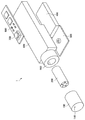
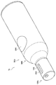
まず、図1〜図5を参照して本実施形態に係る香り提供装置1について説明する。図1は、本実施形態に係る香り提供装置1の一例を示す斜視図である。図2は、本実施形態に係る香り提供装置1の一例を示す断面斜視図である。図3は、本実施形態に係る香り提供装置1の一例を示す分解斜視図である。なお、以下では、香り提供装置1において蓋100の吐出口110が配置される側を先端側と呼ぶ。
<1. Aroma providing device>
First, the scent providing device 1 according to the present embodiment will be described with reference to FIGS. 1 to 5. FIG. 1 is a perspective view showing an example of a scent providing device 1 according to the present embodiment. FIG. 2 is a sectional perspective view showing an example of the scent providing device 1 according to the present embodiment. FIG. 3 is an exploded perspective view showing an example of the scent providing device 1 according to the present embodiment. In the following, the side of the lid 100 on which the ejection port 110 is arranged is referred to as the tip side.

図1〜図3に示したように、本実施形態に係る香り提供装置1は、蓋100と、香料保持部材200と、エアポンプ300と、バッテリ400と、回転機構500と、シャーシ600と、スイッチ700と、基板800と、を備える。 As shown in FIGS. 1 to 3, the scent providing device 1 according to the present embodiment includes a lid 100, a fragrance holding member 200, an air pump 300, a battery 400, a rotating mechanism 500, a chassis 600, and a switch. A substrate 700 and a substrate 800 are provided.

蓋100は、香料保持部材200を外部から離隔する部材である。蓋100は、例えば、図1〜図3に示したように、後端側が開口する円筒形状を有する。蓋100の先端側には、香料保持部材200から送られる気化した香料を含む空気が吐出される吐出口110が設けられる。吐出口110は、香料保持部材200に設けられる複数の保持通路210のうち空気が供給される保持通路210の先端部と連通するように設けられる。吐出口110の内径は、保持通路210の内径より大きくてもよい。 The lid 100 is a member that separates the fragrance holding member 200 from the outside. The lid 100 has, for example, as shown in FIGS. 1 to 3, a cylindrical shape whose rear end side is open. A discharge port 110 for discharging the air containing the vaporized perfume sent from the perfume holding member 200 is provided on the front end side of the lid 100. The discharge port 110 is provided so as to communicate with the tip of the holding passage 210 to which air is supplied among the plurality of holding passages 210 provided in the fragrance holding member 200. The inner diameter of the discharge port 110 may be larger than the inner diameter of the holding passage 210.

香料保持部材200は、香料を保持する部材である。香料保持部材200は、例えば、図2及び図3に示したように、中空円筒形状を有する。香料保持部材200には、香料をそれぞれ保持する複数の保持通路210が貫通して設けられる。香料は、例えば、保持通路210の内表面に付着した状態で保持される。香料は、具体的には、精油又はエタノールで希釈された精油等であってもよい。 The fragrance holding member 200 is a member that holds a fragrance. The fragrance holding member 200 has, for example, a hollow cylindrical shape as shown in FIGS. 2 and 3. The fragrance holding member 200 is provided with a plurality of holding passages 210 that respectively hold fragrances. The fragrance is held in a state of being attached to the inner surface of the holding passage 210, for example. Specifically, the fragrance may be an essential oil, an essential oil diluted with ethanol, or the like.

複数の保持通路210は、例えば、香料保持部材200の中心軸まわりの円周上に均等間隔で設けられ、後端側から先端側に直線状に設けられる。複数の保持通路210のうちの一部の保持通路210には、エアポンプ300から供給される空気が送られる。それにより、保持通路210の後端側から先端側への空気の流れが生じる。そして、保持通路210に保持される香料の気化した成分が蓋100の吐出口110から吐出される。図2では、エアポンプ300と保持通路210との間の空気の流路として、シャーシ600の流路610が示されているが、シャーシ600の流路610と保持通路210の間には他の流路が介在し得る。エアポンプ300と保持通路210との間の空気の流路の詳細については後述する。 The plurality of holding passages 210 are provided, for example, at equal intervals on the circumference around the central axis of the fragrance holding member 200, and are provided linearly from the rear end side to the front end side. The air supplied from the air pump 300 is sent to a part of the plurality of holding passages 210. This causes a flow of air from the rear end side to the front end side of the holding passage 210. Then, the vaporized component of the fragrance held in the holding passage 210 is discharged from the discharge port 110 of the lid 100. In FIG. 2, the flow path 610 of the chassis 600 is shown as a flow path of air between the air pump 300 and the holding passage 210, but another flow path is provided between the flow path 610 of the chassis 600 and the holding passage 210. Roads can intervene. Details of the air flow path between the air pump 300 and the holding passage 210 will be described later.

保持通路210を構成する材料として、例えば、アクリル樹脂、ウレタン樹脂、ABS樹脂、PEEK(ポリエーテルエーテルケトン)、POM(ポリアセタール)、シリコン樹脂、フッ素樹脂、オレフィンポリマー樹脂若しくはポリイミド樹脂等の樹脂、ステンレス等の金属、又はガラスが挙げられる。保持通路210を構成する材料は、具体的には、耐薬品性、耐候性及び強度等を考慮して選択され得る。保持通路210の内径は、一例として、1mmより小さい値に設定され得る。このような微小な内径を有するマイクロ流路である保持通路210は、例えば、3Dプリンタを用いて積層造形法によって製造され得る。 Examples of the material forming the holding passage 210 include acrylic resin, urethane resin, ABS resin, PEEK (polyether ether ketone), POM (polyacetal), silicone resin, fluororesin, olefin polymer resin or polyimide resin, and stainless steel. And the like, or glass. The material forming the holding passage 210 can be specifically selected in consideration of chemical resistance, weather resistance, strength and the like. For example, the inner diameter of the holding passage 210 may be set to a value smaller than 1 mm. The holding passage 210, which is a micro flow path having such a minute inner diameter, can be manufactured by the additive manufacturing method using a 3D printer, for example.

保持通路210の内径が小さいほど、保持通路210内における流体の乱流の発生が抑制されやすくなり、流体の流れは層流になりやすくなる。また、エアポンプ300の出力が一定である場合において、保持通路210の内径が小さいほど、保持通路210内での空気の流速は速くなる。それにより、本実施形態に係る香り提供装置1では、吐出口110から吐出される香料の気化した成分を含む空気の直進性が向上される。ゆえに、香り提供装置1のユーザに向けて香料の気化した成分を含む空気を吐出させることによって、ユーザの周囲へ影響を与えることなくユーザは香りの提供を受けることができる。 The smaller the inner diameter of the holding passage 210, the more easily the generation of turbulent flow of fluid in the holding passage 210 is suppressed, and the flow of fluid becomes laminar. Further, when the output of the air pump 300 is constant, the smaller the inner diameter of the holding passage 210, the faster the flow velocity of air in the holding passage 210. As a result, in the scent providing device 1 according to the present embodiment, the straightness of the air containing the vaporized component of the fragrance discharged from the discharge port 110 is improved. Therefore, by ejecting the air containing the vaporized component of the fragrance toward the user of the scent providing device 1, the user can be provided with the scent without affecting the surroundings of the user.

また、保持通路210の内径が小さいほど、保持通路210内の横断面において、空気が通過する領域に対する香料が保持されている領域の割合が大きくなる。ゆえに、保持通路210内を通過し吐出口110から吐出される空気に含まれる香料の割合が大きくなる。それにより、より確実にユーザへ香りを提供することができる。また、保持通路210の内径を小さくすることによって、装置全体の寸法を小さくすることができるので、装置全体の重量を軽くすることができる。ゆえに、香り提供装置1の持ち運びを容易にすることができる。 Further, the smaller the inner diameter of the holding passage 210, the larger the ratio of the area in which the fragrance is held to the area through which air passes in the cross section of the holding passage 210. Therefore, the proportion of the fragrance contained in the air passing through the holding passage 210 and discharged from the discharge port 110 increases. Thereby, the scent can be provided to the user more reliably. Further, by reducing the inner diameter of the holding passage 210, it is possible to reduce the size of the entire device, so that the weight of the entire device can be reduced. Therefore, the scent providing device 1 can be easily carried.

エアポンプ300は、本開示に係る風力源の一例である。エアポンプ300は、例えば、流路610及び他の図示しない流路を介して、複数の保持通路210のうちの一部の保持通路210へ空気を供給する。エアポンプ300は、例えば、基板800を介してバッテリ400と電気的に接続されており、バッテリ400から供給される電力によって駆動される。エアポンプ300は、具体的には、圧電素子が貼り付けられたダイヤフラムを備え、圧電素子への交流電流の印加によりダイヤフラムを変形させることによって送風を行う。なお、エアポンプ300の送風の形式は係る例に限定されず、例えば、フィン式又はシリンダ式等であってもよい。また、エアポンプ300は手動式であってもよく、その場合には、香り提供装置1の構成からバッテリ400、スイッチ700及び基板800は省略され得る。 The air pump 300 is an example of a wind power source according to the present disclosure. The air pump 300 supplies air to some of the holding passages 210 among the plurality of holding passages 210, for example, via the passage 610 and other passages (not shown). The air pump 300 is electrically connected to the battery 400 via the substrate 800, for example, and is driven by the electric power supplied from the battery 400. Specifically, the air pump 300 includes a diaphragm to which a piezoelectric element is attached, and blows air by deforming the diaphragm by applying an alternating current to the piezoelectric element. The type of air blown by the air pump 300 is not limited to this example, and may be, for example, a fin type or a cylinder type. Further, the air pump 300 may be a manual type, and in that case, the battery 400, the switch 700, and the substrate 800 may be omitted from the configuration of the scent providing device 1.

バッテリ400は、エアポンプ300を動作させるための電力を蓄える。バッテリ400は、放電のみが可能な一次電池であってもよく、充電も可能な二次電池であってもよい。 Battery 400 stores electric power for operating air pump 300. The battery 400 may be a primary battery that can only be discharged or a secondary battery that can be charged.

回転機構500は、複数の保持通路210のうちの一部の保持通路210と連通し、一部の保持通路210へエアポンプ300から供給される空気を導入する導入口が設けられる部材と香料保持部材200とを、当該導入口と連通する一部の保持通路210が切り替わるように、相対的に回転可能である。図1〜3に示した回転機構500は概念図であるので、回転機構500の詳細については後述する。 The rotation mechanism 500 communicates with a part of the plurality of holding passages 210 and is provided with an inlet for introducing the air supplied from the air pump 300 to the part of the holding passages 210 and a perfume holding member. 200 and 200 can be relatively rotated so that a part of the holding passage 210 communicating with the introduction port is switched. Since the rotating mechanism 500 shown in FIGS. 1 to 3 is a conceptual diagram, details of the rotating mechanism 500 will be described later.

シャーシ600には、エアポンプ300、バッテリ400、回転機構500及び基板800が配設される。また、シャーシ600には、必要に応じて、各部品間を電気的に接続する配線が設けられ得る。 An air pump 300, a battery 400, a rotation mechanism 500, and a substrate 800 are arranged on the chassis 600. In addition, the chassis 600 may be provided with wiring that electrically connects the components, as necessary.

スイッチ700は、エアポンプ300の駆動状態を切り替えるために基板800に設けられる。基板800はバッテリ400と電気的に接続されており、例えば、スイッチ700がユーザに押下されることによって、基板800に実装されたエアポンプ300を駆動するための駆動回路への通電が行われる。それにより、ユーザによるスイッチ700の押下状態に応じて、エアポンプ300の駆動状態が切り替わる。 The switch 700 is provided on the substrate 800 to switch the driving state of the air pump 300. The board 800 is electrically connected to the battery 400. For example, when the switch 700 is pressed by the user, the drive circuit for driving the air pump 300 mounted on the board 800 is energized. As a result, the driving state of the air pump 300 is switched according to the pressed state of the switch 700 by the user.

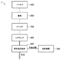
図4は、本実施形態に係る香り提供装置1の一例を示すシステムブロック図である。図4に示したように、バッテリ400及び基板800は電気的に接続されている。そして、スイッチ700が押下されると、基板800に実装されたエアポンプ300を駆動するための駆動回路への通電が行われ、エアポンプ300が駆動される。それにより、エアポンプ300が送風を開始し、エアポンプ300から供給された空気が、香料保持部材200の保持通路210へ送られる。そして、香料保持部材200の保持通路210に保持される香料の気化した成分が蓋100の吐出口110から外部へ吐出される。香料保持部材200の複数の保持通路210のうち空気が導入される保持通路210の回転機構500による切り替えは、手動で行われる。 FIG. 4 is a system block diagram showing an example of the scent providing device 1 according to the present embodiment. As shown in FIG. 4, the battery 400 and the substrate 800 are electrically connected. Then, when the switch 700 is pressed, the drive circuit for driving the air pump 300 mounted on the substrate 800 is energized, and the air pump 300 is driven. As a result, the air pump 300 starts blowing air, and the air supplied from the air pump 300 is sent to the holding passage 210 of the fragrance holding member 200. Then, the vaporized component of the fragrance held in the holding passage 210 of the fragrance holding member 200 is discharged to the outside from the discharge port 110 of the lid 100. Switching among the plurality of holding passages 210 of the fragrance holding member 200 through which the air is introduced by the rotation mechanism 500 is manually performed.

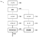
本明細書では、図4を用いて説明したように、空気が導入される保持通路210の回転機構500による切り替えが手動で行われる香り提供装置1を主として説明するが、回転機構500による切り替えの形式は係る例に限定されず、例えば、回転機構500は、モータによって駆動されてもよい。このような他の実施形態に係る香り提供装置1aには回転機構500を駆動させるモータ310と、基板800に実装されるモータ310を駆動させるための駆動回路への通電の切り替えを行うスイッチ710と、が備えられる。香り提供装置1aによれば、例えば、図5に示したように、スイッチ710が押下されると、基板800に実装されるモータ310を駆動させるための駆動回路への通電が行われ、モータ310が駆動される。それにより、モータ310により回転機構500が駆動され、香料保持部材200の複数の保持通路210のうち空気が導入される保持通路210の回転機構500による切り替えが行われる。 In the present specification, as described with reference to FIG. 4, the scent providing device 1 in which the switching of the holding passage 210 into which air is introduced is manually performed by the rotation mechanism 500 will be mainly described. The form is not limited to such an example, and for example, the rotation mechanism 500 may be driven by a motor. In the scent providing device 1a according to such another embodiment, a motor 310 that drives the rotation mechanism 500, and a switch 710 that switches energization to a drive circuit that drives the motor 310 mounted on the substrate 800. , Are provided. According to the scent providing device 1a, for example, as shown in FIG. 5, when the switch 710 is pressed, the drive circuit for driving the motor 310 mounted on the substrate 800 is energized, and the motor 310 is driven. Is driven. Thereby, the rotation mechanism 500 is driven by the motor 310, and the holding mechanism 210 of the plurality of holding passages 210 of the perfume holding member 200 into which air is introduced is switched by the rotation mechanism 500.

<2.回転機構>
[2−1.第1の例]
続いて、図6〜図8を参照して、第1の例に係る回転機構501について説明する。図6及び図7は、第1の例に係る香料保持部材200及び回転機構501の構成の一例を示す説明図である。図6は、エアポンプ300から供給される空気が送られる保持通路210aを通る断面における断面図を示し、図7は、エアポンプ300から供給される空気が送られない保持通路210bを通る断面における断面図を示す。図8は、図6に示したB1−B1断面の一例を示す断面図である。図6及び図7に示したように、第1の例に係る回転機構501は、回転伝達部510と、空気導入部520と、を含む。第1の例に係る回転機構501において、回転伝達部510の回転は、香料保持部材200へ伝達されるように構成される。また、香料保持部材200及び回転伝達部510は、空気導入部520に対して回転可能である。以下、このような回転機構501の詳細について説明する。
<2. Rotation mechanism>
[2-1. First example]
Subsequently, the rotation mechanism 501 according to the first example will be described with reference to FIGS. 6 to 8. 6 and 7 are explanatory diagrams showing an example of the configurations of the fragrance holding member 200 and the rotation mechanism 501 according to the first example. FIG. 6 is a cross-sectional view of a cross section passing through the holding passage 210a to which the air supplied from the air pump 300 is sent, and FIG. 7 is a cross-sectional view of a cross section passing through the holding passage 210b to which the air supplied from the air pump 300 is not sent. Indicates. FIG. 8 is a cross-sectional view showing an example of the B1-B1 cross section shown in FIG. As shown in FIGS. 6 and 7, the rotation mechanism 501 according to the first example includes a rotation transmission unit 510 and an air introduction unit 520. In the rotation mechanism 501 according to the first example, the rotation of the rotation transmission unit 510 is configured to be transmitted to the fragrance holding member 200. Further, the fragrance holding member 200 and the rotation transmitting section 510 can rotate with respect to the air introducing section 520. Hereinafter, the details of the rotating mechanism 501 will be described.

空気導入部520は、後端側に位置する大径部522と、大径部522の先端側の中央部に設けられ先端方向へ突出する小径部524と、を含む。大径部522及び小径部524は、例えば、それぞれ略円柱形状を有する。大径部522には、エアポンプ300から供給される空気を保持通路210aへ導くための流路522aが設けられる。例えば、流路522aの後端部は、図2に示したシャーシ600の流路610の先端部と連通する。それにより、エアポンプ300から供給される空気は、流路610を介して流路522aへ送られる。流路522aの先端部には、保持通路210aと連通し、保持通路210aへエアポンプ300から供給される空気を導入する導入口522bが設けられる。導入口522bは、他の流路を介して保持通路210aと連通してもよく、例えば、図6に示したように、回転伝達部510に設けられる流路514bを介して保持通路210aと連通してもよい。 The air introduction part 520 includes a large diameter part 522 located on the rear end side and a small diameter part 524 provided in the central part on the tip side of the large diameter part 522 and protruding in the tip direction. The large diameter portion 522 and the small diameter portion 524 each have, for example, a substantially cylindrical shape. The large diameter portion 522 is provided with a flow path 522a for guiding the air supplied from the air pump 300 to the holding passage 210a. For example, the rear end of the flow channel 522a communicates with the front end of the flow channel 610 of the chassis 600 shown in FIG. As a result, the air supplied from the air pump 300 is sent to the flow channel 522a via the flow channel 610. An inlet 522b, which communicates with the holding passage 210a and introduces the air supplied from the air pump 300 into the holding passage 210a, is provided at the tip of the flow passage 522a. The introduction port 522b may communicate with the holding passage 210a via another flow passage, and, for example, as shown in FIG. 6, may communicate with the holding passage 210a via a passage 514b provided in the rotation transmission unit 510. You may.

回転伝達部510は、香料保持部材200の後端側の外周部を保持する円筒部512と、円筒部512の後端部の内周側に設けられ香料保持部材200の後端部を保持する底部514と、を含む。円筒部512の内周部には、香料保持部材200が嵌合される。なお、円筒部512の形状は、特に限定されず、香料保持部材200と嵌合可能な形状であればよい。香料保持部材200の回転伝達部510に対する軸方向への移動は、例えば、香料保持部材200の円筒部512への軽圧入によって拘束される。なお、香料保持部材200の回転伝達部510に対する軸方向への移動をより確実に拘束するために、円筒部512の外周部を内周部側へ付勢する機構が適用されてもよい。 The rotation transmitting portion 510 is provided on the cylindrical portion 512 that holds the outer peripheral portion on the rear end side of the fragrance holding member 200 and the inner peripheral side of the rear end portion of the cylindrical portion 512, and holds the rear end portion of the fragrance holding member 200. And a bottom portion 514. The perfume holding member 200 is fitted to the inner peripheral portion of the cylindrical portion 512. The shape of the cylindrical portion 512 is not particularly limited as long as it can be fitted to the flavor holding member 200. The movement of the fragrance holding member 200 in the axial direction with respect to the rotation transmitting portion 510 is restrained by, for example, light press-fitting into the cylindrical portion 512 of the fragrance holding member 200. A mechanism for urging the outer peripheral portion of the cylindrical portion 512 toward the inner peripheral portion may be applied in order to more reliably restrain the movement of the scent holding member 200 in the axial direction with respect to the rotation transmitting portion 510.

底部514の先端部は香料保持部材200の後端部と対向し、底部514の後端部は空気導入部520の大径部522と小径部524との段差部と対向する。底部514の中央には香料保持部材200の内周部と連通する開口部514aが設けられてもよく、底部514の開口部514a及び香料保持部材200の内周部の内側に空気導入部520の小径部524が挿入されてもよい。小径部524は、例えば、香料保持部材200及び回転機構501の組み立てを容易にするためのガイドとして用いられる。ゆえに、回転機構501の構成から小径部524は省略されてもよい。また、小径部524がガイドとして機能する場合には、小径部524は、香料保持部材200及び回転伝達部510と相対的に回転可能な形状であれば、多角柱や楕円柱等の形状であってもよい。底部514には、香料保持部材200の各保持通路210とそれぞれ連通する流路514bが貫通して設けられる。 The front end of the bottom portion 514 faces the rear end portion of the fragrance holding member 200, and the rear end portion of the bottom portion 514 faces the step portion between the large diameter portion 522 and the small diameter portion 524 of the air introduction portion 520. An opening 514a may be provided in the center of the bottom portion 514 so as to communicate with the inner peripheral portion of the fragrance holding member 200, and the air introduction portion 520 may be provided inside the opening 514a of the bottom portion 514 and the inner peripheral portion of the fragrance holding member 200. The small diameter portion 524 may be inserted. The small diameter portion 524 is used, for example, as a guide for facilitating the assembly of the fragrance holding member 200 and the rotation mechanism 501. Therefore, the small diameter portion 524 may be omitted from the configuration of the rotating mechanism 501. When the small-diameter portion 524 functions as a guide, the small-diameter portion 524 has a polygonal column shape, an elliptic column shape, or the like as long as the small-diameter portion 524 can rotate relative to the fragrance holding member 200 and the rotation transmitting section 510. May be. The bottom portion 514 is provided with a flow path 514b that communicates with each holding passage 210 of the fragrance holding member 200.

円筒部512の内周部には、内側向きに突出する係止凸部512aが設けられる。係止凸部512aは、例えば、円筒部512の軸方向に沿って延設される。図6及び図8に示したように、係止凸部512aは、香料保持部材200の外周部に香料保持部材200の軸方向に沿って延設される係止溝230に嵌合される。それにより、回転伝達部510の回転が香料保持部材200へ伝達される。ゆえに、回転伝達部510を回転させることによって、香料保持部材200を導入口522bに対して回転させることができる。なお、円筒部512側に係止溝が設けられ、香料保持部材200側に係止凸部が設けられてもよい。 A locking convex portion 512 a that projects inward is provided on the inner peripheral portion of the cylindrical portion 512. The locking convex portion 512a is provided, for example, extending along the axial direction of the cylindrical portion 512. As shown in FIGS. 6 and 8, the locking protrusion 512 a is fitted into the locking groove 230 that extends along the axial direction of the perfume holding member 200 on the outer peripheral portion of the perfume holding member 200. Thereby, the rotation of the rotation transmission unit 510 is transmitted to the fragrance holding member 200. Therefore, by rotating the rotation transmitting unit 510, the fragrance holding member 200 can be rotated with respect to the introduction port 522b. A locking groove may be provided on the cylindrical portion 512 side, and a locking convex portion may be provided on the flavor holding member 200 side.

円筒部512の係止凸部512a及び香料保持部材200の係止溝230は、回転伝達部510の回転を香料保持部材200へ伝達する機能を有する機構の一例であり、当該機能を実現するための機構は係る例に限定されない。例えば、香料保持部材200を円筒部512へ軽圧入することによって、当該機能が実現されてもよく、その場合には、回転機構501及び香料保持部材200の構成から係止凸部512a及び係止溝230は省略されてもよい。また、当該機能は、香料保持部材200の横断面形状を多角形や楕円等の円以外の形状とし、円筒部512の香料保持部材200と嵌合される部分の形状を香料保持部材200と対応する形状にすることにより、香料保持部材200と円筒部512との相対的な回転を防止することによって、実現されてもよい。 The locking convex portion 512a of the cylindrical portion 512 and the locking groove 230 of the fragrance holding member 200 are an example of a mechanism having a function of transmitting the rotation of the rotation transmission unit 510 to the fragrance holding member 200, and in order to realize the function. The mechanism of is not limited to this example. For example, this function may be realized by lightly press-fitting the fragrance holding member 200 into the cylindrical portion 512. In that case, the locking projection 512a and the locking projection 512a are locked due to the configuration of the rotation mechanism 501 and the fragrance holding member 200. The groove 230 may be omitted. Further, as for the function, the cross-sectional shape of the fragrance holding member 200 is a shape other than a circle such as a polygon or an ellipse, and the shape of the portion of the cylindrical portion 512 to be fitted with the fragrance holding member 200 corresponds to the fragrance holding member 200. It may be realized by preventing the relative rotation between the fragrance holding member 200 and the cylindrical portion 512 by adopting the shape described above.

回転伝達部510の後端面には、空気導入部520の大径部522の先端側の外周部を覆う環状凸部518が突出して設けられる。環状凸部518の内周部に大径部522の先端側の外周部が嵌合される。環状凸部518は、回転伝達部510の空気導入部520に対する回転のガイドとして機能する。また、環状凸部518の内周部の一部には内側に突出する突起部518aが設けられ、突起部518aが大径部522の外周に沿って形成される環状溝部522fに係止される。それにより、回転伝達部510が空気導入部520に対して相対的に軸方向へ移動することなく、香料保持部材200及び回転伝達部510が空気導入部520に対して回転可能となる。 An annular convex portion 518 is provided on the rear end surface of the rotation transmission portion 510 so as to cover the outer peripheral portion of the large diameter portion 522 of the air introduction portion 520 on the tip side. The outer peripheral portion of the large diameter portion 522 on the tip side is fitted into the inner peripheral portion of the annular convex portion 518. The annular convex portion 518 functions as a rotation guide of the rotation transmitting portion 510 with respect to the air introducing portion 520. Further, a protrusion 518a protruding inward is provided on a part of the inner peripheral portion of the annular protrusion 518, and the protrusion 518a is locked in an annular groove 522f formed along the outer periphery of the large diameter portion 522. .. As a result, the rotation transmitting part 510 does not move in the axial direction relative to the air introducing part 520, and the flavor holding member 200 and the rotation transmitting part 510 can rotate with respect to the air introducing part 520.

香料保持部材200及び回転伝達部510の回転の回転軸は、香料保持部材200、回転伝達部510及び空気導入部520の中心軸と略一致する。香料保持部材200、回転伝達部510の円筒部512及び空気導入部520の大径部522が互いに略一致する中心軸の円筒形状又は円柱形状を有することによって、回転機構500による回転における部材の可動範囲を小さくすることができる。ただし、香料保持部材200、回転伝達部510の円筒部512及び空気導入部520の大径部522の形状は特に限定されるものではない。 The rotation axes of rotation of the fragrance holding member 200 and the rotation transmitting part 510 are substantially the same as the central axes of the fragrance holding member 200, the rotation transmitting part 510, and the air introducing part 520. The fragrance holding member 200, the cylindrical portion 512 of the rotation transmitting portion 510, and the large-diameter portion 522 of the air introducing portion 520 have a cylindrical shape or a cylindrical shape with central axes that substantially coincide with each other, so that the rotation mechanism 500 can move the member. The range can be reduced. However, the shapes of the fragrance holding member 200, the cylindrical portion 512 of the rotation transmitting portion 510, and the large diameter portion 522 of the air introducing portion 520 are not particularly limited.

回転伝達部510の空気導入部520に対する回転のガイドとしての機能は、底部514の開口部514a及び香料保持部材200の内周部の内側に挿入される空気導入部520の小径部524によって実現されてもよい。その場合には、小径部524は底部514の開口部514a及び香料保持部材200の内周部に嵌合され、回転機構501の構成から環状凸部518は省略されてもよい。 The function of the rotation transmitting portion 510 as a guide for rotation with respect to the air introducing portion 520 is realized by the opening 514a of the bottom portion 514 and the small diameter portion 524 of the air introducing portion 520 inserted inside the inner peripheral portion of the fragrance holding member 200. May be. In that case, the small diameter portion 524 may be fitted into the opening 514 a of the bottom portion 514 and the inner peripheral portion of the fragrance holding member 200, and the annular convex portion 518 may be omitted from the configuration of the rotating mechanism 501.

第1の例に係る回転機構501は、回転伝達部510を空気導入部520に対して回転可能とし、導入口522bと連通する保持通路210が切り替わるように、香料保持部材200を導入口522bが設けられる部材である空気導入部520に対して回転可能である。香料保持部材200の複数の保持通路210は、例えば、回転機構501による空気導入部520と香料保持部材200との相対的な回転の回転軸まわりの円周上に設けられる。具体的には、香料保持部材200の複数の保持通路210は、香料保持部材200の中心軸まわりの円周上に設けられる。ここで、香料保持部材200は、香料保持部材200の中心軸まわりに回転する。ゆえに、香料保持部材200を空気導入部520に対して回転させることによって、導入口522bと連通する保持通路210を切り替えることができる。 The rotation mechanism 501 according to the first example allows the rotation transmission part 510 to rotate with respect to the air introduction part 520, and the fragrance holding member 200 has the introduction port 522b so that the holding passage 210 communicating with the introduction port 522b is switched. It is rotatable with respect to the air introduction part 520 which is a member provided. The plurality of holding passages 210 of the fragrance holding member 200 are provided, for example, on the circumference around the rotation axis of the relative rotation between the air introducing portion 520 and the fragrance holding member 200 by the rotating mechanism 501. Specifically, the plurality of holding passages 210 of the fragrance holding member 200 are provided on the circumference around the central axis of the fragrance holding member 200. Here, the fragrance holding member 200 rotates around the central axis of the fragrance holding member 200. Therefore, by rotating the fragrance holding member 200 with respect to the air introduction part 520, the holding passage 210 communicating with the introduction port 522b can be switched.

各保持通路210には互いに異なる種類の香料を保持させてもよく、その場合には、導入口522bと連通する保持通路210を切り替えることによって、香り提供装置1によって提供される香りを切り替えることができる。なお、各保持通路210には互いに同一の種類の香料を保持させてもよい。例えば、使用頻度の高い香料ほど多くの保持通路210に保持させることによって、各香料の使用頻度に応じて適切に各香料の持続時間を設定することができる。 Different fragrances may be held in the respective holding passages 210. In that case, the scent provided by the scent providing device 1 can be switched by switching the holding passages 210 communicating with the inlet 522b. it can. The holding passages 210 may hold the same type of fragrance. For example, by holding the more frequently used fragrances in the holding passage 210, the duration of each fragrance can be appropriately set according to the usage frequency of each fragrance.

以上説明したように、本実施形態に係る香り提供装置1によれば、香料をそれぞれ保持する複数の空間の各々への空気の供給を1つの風力源によって実現することができるので、当該空間の数を増加させる場合における風力源の数の増加に伴う装置の大型化を抑制することができる。よって、装置を小型化することが可能である。 As described above, according to the scent providing device 1 according to the present embodiment, it is possible to realize the supply of air to each of the plurality of spaces holding the fragrance by using one wind power source. It is possible to suppress an increase in the size of the device due to an increase in the number of wind power sources when the number is increased. Therefore, the device can be downsized.

なお、蓋100が香料保持部材200に対して固定される場合には、蓋100は香料保持部材200の回転とともに回転する。係る場合には、蓋100には保持通路210と同数の吐出口110が設けられ、各吐出口110は各保持通路210の先端部と連通するように設けられる。一方、蓋100が、回転伝達部510に対して固定される場合には、香料保持部材200が蓋100に対して回転する。係る場合には、蓋100には1つの吐出口110が設けられ、当該1つの吐出口110は導入口522bの先端部と連通する保持通路210aと連通するように設けられる。 When the lid 100 is fixed to the fragrance holding member 200, the lid 100 rotates with the rotation of the fragrance holding member 200. In such a case, the lid 100 is provided with the same number of ejection openings 110 as the holding passages 210, and each ejection opening 110 is provided so as to communicate with the tip end portion of each holding passage 210. On the other hand, when the lid 100 is fixed to the rotation transmission unit 510, the flavor holding member 200 rotates with respect to the lid 100. In this case, the lid 100 is provided with one discharge port 110, and the one discharge port 110 is provided so as to communicate with the holding passage 210a that communicates with the tip portion of the introduction port 522b.

また、上述したように、香料保持部材200は、空気導入部520と香料保持部材200との相対的な回転の回転軸と中心軸が略一致する円筒形状を有する。それにより、導入口522bと連通する保持通路210の切り替えにおける部材の可動範囲を小さくすることができるので、装置をより小型化することができる。 In addition, as described above, the fragrance holding member 200 has a cylindrical shape in which the central axis and the rotation axis of the relative rotation between the air introduction portion 520 and the fragrance holding member 200 are substantially coincident with each other. As a result, the movable range of the member in switching the holding passage 210 communicating with the introduction port 522b can be reduced, so that the device can be further downsized.

回転機構500は、導入口522bが保持通路210と連通するように、空気導入部520と香料保持部材200との相対的な回転の回転角を規定する位置決め機構を備える。具体的には、当該位置決め機構は、空気導入部520又は香料保持部材200を係止する係止部材及び係止部材を付勢する付勢部材を備える。図7に示した鋼球522cは回転伝達部510を介して香料保持部材200を係止する係止部材の一例であり、バネ522dは付勢部材の一例である。 The rotation mechanism 500 includes a positioning mechanism that defines a rotation angle of relative rotation between the air introduction portion 520 and the fragrance holding member 200 so that the introduction port 522b communicates with the holding passage 210. Specifically, the positioning mechanism includes a locking member that locks the air introduction part 520 or the fragrance holding member 200 and a biasing member that biases the locking member. The steel ball 522c shown in FIG. 7 is an example of a locking member that locks the fragrance holding member 200 via the rotation transmission unit 510, and the spring 522d is an example of a biasing member.

図6及び図7に示したように、回転伝達部510の後端面のうち空気導入部520の大径部522と小径部524との段差部と対向する部分には、窪み516が設けられる。また、空気導入部520の大径部522と小径部524との段差部には、鋼球522c及びバネ522dが設けられる。バネ522dは、大径部522と小径部524との段差部に形成された空気導入部520の軸方向に穿孔された孔522eに収容され、バネ522dの先端側に鋼球522cが設けられる。バネ522d及び鋼球522cのペアは、例えば、図7に示したように、2つ設けられる。なお、当該ペアの数は、1以上の他の数であってもよい。窪み516は、各保持通路210についてバネ522d及び鋼球522cのペアの数と同数設けられる。窪み516の配置は、各保持通路210の香料保持部材200における周方向の位置に応じて設定される。 As shown in FIGS. 6 and 7, a recess 516 is provided in a portion of the rear end surface of the rotation transmitting portion 510 facing the step portion between the large diameter portion 522 and the small diameter portion 524 of the air introducing portion 520. Further, a steel ball 522c and a spring 522d are provided at a step portion between the large diameter portion 522 and the small diameter portion 524 of the air introduction portion 520. The spring 522d is housed in a hole 522e formed in the axial direction of the air introduction part 520 formed at the step between the large diameter part 522 and the small diameter part 524, and a steel ball 522c is provided on the tip side of the spring 522d. Two pairs of the spring 522d and the steel ball 522c are provided, for example, as shown in FIG. The number of the pair may be one or more other numbers. The depressions 516 are provided in the same number as the number of pairs of the springs 522d and the steel balls 522c for each holding passage 210. The arrangement of the depressions 516 is set according to the circumferential position of each holding passage 210 in the perfume holding member 200.

具体的には、導入口522bが保持通路210aと連通する状態において、鋼球522cの先端側にいずれかの窪み516が位置するように、回転伝達部510の後端面における窪み516の配置が設定される。ゆえに、導入口522bが複数の保持通路210のいずれかと連通する場合には、鋼球522cがバネ522dの付勢力によって窪み516へ押し付けられることにより、回転伝達部510は空気導入部520に対して位置決めされる。それにより、導入口522bと連通する保持通路210の切り替えをより容易に行うことができる。 Specifically, the arrangement of the depressions 516 on the rear end surface of the rotation transmitting portion 510 is set so that any depressions 516 are located on the tip side of the steel ball 522c in a state where the introduction port 522b communicates with the holding passage 210a. To be done. Therefore, when the introduction port 522b communicates with any one of the plurality of holding passages 210, the steel ball 522c is pressed against the recess 516 by the biasing force of the spring 522d, so that the rotation transmission section 510 moves relative to the air introduction section 520. Positioned. Accordingly, the holding passage 210 communicating with the introduction port 522b can be switched more easily.

一方、導入口522bが複数の保持通路210のいずれとも連通していない状態において、鋼球522cの先端側にいずれの窪み516も位置しないように、回転伝達部510の後端面における窪み516の配置が設定される。ゆえに、導入口522bが複数の保持通路210のいずれとも連通していない場合には、鋼球522cはバネ522dと共に、孔522eの内部に収容されるので、回転伝達部510の空気導入部520に対する回転を円滑に行うことができる。 On the other hand, in a state in which the introduction port 522b is not in communication with any of the plurality of holding passages 210, the arrangement of the recess 516 on the rear end surface of the rotation transmitting unit 510 is arranged so that no recess 516 is located on the tip side of the steel ball 522c. Is set. Therefore, when the introduction port 522b is not in communication with any of the plurality of holding passages 210, the steel ball 522c is housed inside the hole 522e together with the spring 522d, so that the rotation transmission unit 510 is connected to the air introduction unit 520. It can rotate smoothly.

また、係止部材が付勢される方向は、空気導入部520と香料保持部材200との相対的な回転の回転軸に交差する方向であってもよい。例えば、係止部材及び付勢部材が回転伝達部510の外周側に設けられ、回転伝達部510の径方向へ係止部材が付勢されることによって、上記位置決め機構の機能が実現され得る。その場合には、例えば、回転伝達部510の外周部に窪みが設けられ得る。 Further, the direction in which the locking member is biased may be a direction intersecting the rotation axis of the relative rotation between the air introduction portion 520 and the fragrance holding member 200. For example, the locking member and the biasing member are provided on the outer peripheral side of the rotation transmitting portion 510, and the locking member is biased in the radial direction of the rotation transmitting portion 510, whereby the function of the positioning mechanism can be realized. In that case, for example, a depression may be provided on the outer peripheral portion of the rotation transmitting unit 510.

[2−2.第2の例]
以上では、回転機構501が香料保持部材200を導入口522bが設けられる部材である空気導入部520に対して回転可能である第1の例について説明したが、回転機構の構成は係る例に限定されず、回転機構は、導入口が設けられる部材を香料保持部材に対して回転可能であってもよい。以下、図9及び図10を参照して、回転機構によって導入口が設けられる部材を香料保持部材に対して回転可能な第2の例について説明する。
[2-2. Second example]
In the above, the first example in which the rotation mechanism 501 can rotate the fragrance holding member 200 with respect to the air introduction part 520 that is a member provided with the introduction port 522b has been described, but the configuration of the rotation mechanism is limited to such an example. Alternatively, the rotation mechanism may be capable of rotating the member provided with the introduction port with respect to the fragrance holding member. Hereinafter, with reference to FIG. 9 and FIG. 10, a second example in which the member provided with the introduction port by the rotation mechanism can be rotated with respect to the fragrance holding member will be described.

図9及び図10は、第2の例に係る香料保持部材200及び回転機構502の構成の一例を示す説明図である。図9は、蓋100aの記載を省略した説明図であり、図10は、蓋100aの記載を含む説明図である。図9及び図10に示したように、第2の例に係る回転機構502は、空気導入部560と、位置決め部570と、筐体580と、を含む。第2の例に係る回転機構502において、空気導入部560は、香料保持部材200に対して回転可能である。以下、このような回転機構502の詳細について説明する。 9 and 10 are explanatory diagrams showing an example of the configurations of the fragrance holding member 200 and the rotation mechanism 502 according to the second example. 9 is an explanatory diagram in which the description of the lid 100a is omitted, and FIG. 10 is an explanatory diagram including the description of the lid 100a. As shown in FIGS. 9 and 10, the rotation mechanism 502 according to the second example includes an air introduction unit 560, a positioning unit 570, and a housing 580. In the rotation mechanism 502 according to the second example, the air introduction part 560 is rotatable with respect to the fragrance holding member 200. The details of the rotating mechanism 502 will be described below.

空気導入部560は、後端側に位置する大径部562と、大径部562の先端側の中央部に設けられた先端方向へ突出する突出部である小径部564と、を含む。大径部562及び小径部564は、例えば、それぞれ略円筒形状を有する。大径部562にはエアポンプ300から供給される空気を保持通路210aへ導くための流路562aが設けられる。流路562aの後端部は、位置決め部570に設けられる流路572と連通する。また、位置決め部570に設けられる流路572の後端部は、シャーシ600の流路610の先端部と連通する。それにより、エアポンプ300から供給される空気は、流路610及び流路572を介して流路562aへ送られる。流路562aの先端部には、保持通路210aと連通し、保持通路210aへエアポンプ300から供給される空気を導入する導入口562bが設けられる。導入口562bは、他の流路を介して保持通路210aと連通してもよい。 The air introduction portion 560 includes a large diameter portion 562 located on the rear end side and a small diameter portion 564 that is a protrusion portion that is provided in the central portion on the tip end side of the large diameter portion 562 and that protrudes toward the tip end. The large diameter portion 562 and the small diameter portion 564 have, for example, substantially cylindrical shapes. The large diameter portion 562 is provided with a flow path 562a for guiding the air supplied from the air pump 300 to the holding passage 210a. The rear end of the flow channel 562a communicates with the flow channel 572 provided in the positioning unit 570. Further, the rear end of the flow path 572 provided in the positioning portion 570 communicates with the front end of the flow path 610 of the chassis 600. Thereby, the air supplied from the air pump 300 is sent to the flow path 562a via the flow paths 610 and 572. An inlet 562b, which communicates with the holding passage 210a and introduces air supplied from the air pump 300 into the holding passage 210a, is provided at the tip of the flow passage 562a. The introduction port 562b may communicate with the holding passage 210a via another flow path.

また、大径部562の後端部には、外周方向へ突出する鍔部562cが設けられる。シャーシ600には、鍔部562cに対応する形状の凹部が形成されており、鍔部562cがシャーシ600の当該凹部に支持されることにより、空気導入部560の並進方向への移動は拘束される。また、当該凹部は、空気導入部560のシャーシ600に対する回転のガイドとして機能し得る。それにより、空気導入部560は、シャーシ600に対して回転可能となる。 Further, at the rear end of the large diameter portion 562, a collar portion 562c protruding in the outer peripheral direction is provided. A recess having a shape corresponding to the flange 562c is formed in the chassis 600, and the flange 562c is supported by the recess of the chassis 600, whereby movement of the air introducing unit 560 in the translational direction is restricted. .. In addition, the recess can function as a guide for rotation of the air introduction part 560 with respect to the chassis 600. Thereby, the air introduction part 560 can rotate with respect to the chassis 600.

小径部564は、香料保持部材200の内周部の内側に挿入され、香料保持部材200の軸方向に延設される。香料保持部材200を貫通する小径部564の先端部には、図10に示したように、香料保持部材200を外部から離隔する蓋100aの後端面から後端方向へ突出する突起部120が挿入される凹部564aが設けられる。それにより、図10に示したように、蓋100aの突起部120が小径部564の凹部564aに挿入された状態で蓋100aを回転させることによって、空気導入部560を香料保持部材200に対して回転させることができる。 The small diameter portion 564 is inserted inside the inner peripheral portion of the fragrance holding member 200 and extends in the axial direction of the fragrance holding member 200. As shown in FIG. 10, the protrusion 120 protruding from the rear end surface of the lid 100a that separates the fragrance holding member 200 from the outside toward the rear end is inserted into the tip of the small diameter portion 564 that penetrates the fragrance holding member 200. A recessed portion 564a is provided. As a result, as shown in FIG. 10, by rotating the lid 100a with the protrusion 120 of the lid 100a inserted in the recess 564a of the small diameter portion 564, the air introduction portion 560 is moved relative to the flavor holding member 200. It can be rotated.

空気導入部560のシャーシ600に対する回転のガイドとしての機能は、香料保持部材200の内周部の内側に挿入される空気導入部560の小径部564によって実現されてもよい。その場合には、小径部564は香料保持部材200の内周部に嵌合される。 The function of the air introducing portion 560 as a guide for rotation with respect to the chassis 600 may be realized by the small diameter portion 564 of the air introducing portion 560 inserted inside the inner peripheral portion of the fragrance holding member 200. In that case, the small diameter portion 564 is fitted to the inner peripheral portion of the fragrance holding member 200.

筐体580は、香り提供装置を構成する他の部材のうち香料保持部材200の先端側の一部を除く部材を収容する部材であり、シャーシ600は筐体580の内部に固定されている。筐体580の先端部には、蓋100aの後端部が接続される。それにより、蓋100a及び筐体580により、香り提供装置を構成する他の部材が収容される。ここで、蓋100aは筐体580に対して回転自在となるように構成される。 The housing 580 is a member that houses a member other than a part of the fragrance holding member 200 on the tip side of the other members constituting the scent providing device, and the chassis 600 is fixed inside the housing 580. The rear end of the lid 100a is connected to the front end of the housing 580. As a result, the lid 100a and the housing 580 accommodate other components that form the scent providing device. Here, the lid 100 a is configured to be rotatable with respect to the housing 580.

また、図9及び図10に示したように、筐体580の先端部の内周部には、内側向きに突出する係止凸部582が設けられる。係止凸部582は、例えば、香料保持部材200の軸方向に沿って延設される。係止凸部582は、香料保持部材200の外周部に香料保持部材200の軸方向に沿って延設される係止溝230に嵌合される。それにより、空気導入部560を回転させた場合に香料保持部材200が回転することを防止し、空気導入部560を香料保持部材200に対して回転させることができる。ゆえに、空気導入部560の導入口562bを香料保持部材200に対して回転させることができる。なお、筐体580側に係止溝が設けられ、香料保持部材200側に係止凸部が設けられてもよい。 Further, as shown in FIGS. 9 and 10, a locking projection 582 that projects inward is provided on the inner peripheral portion of the tip of the housing 580. The locking protrusion 582 extends, for example, along the axial direction of the fragrance holding member 200. The locking protrusion 582 is fitted into a locking groove 230 that extends along the axial direction of the fragrance holding member 200 on the outer peripheral portion of the fragrance holding member 200. This prevents the fragrance holding member 200 from rotating when the air introducing unit 560 is rotated, and allows the air introducing unit 560 to rotate with respect to the fragrance holding member 200. Therefore, the introduction port 562b of the air introduction unit 560 can be rotated with respect to the fragrance holding member 200. A locking groove may be provided on the housing 580 side and a locking projection may be provided on the flavor holding member 200 side.

筐体580の係止凸部582及び香料保持部材200の係止溝230は、空気導入部560を回転させた場合に香料保持部材200が回転することを防止する機能を有する機構の一例であり、当該機能を実現するための機構は係る例に限定されない。例えば、香料保持部材200を筐体580へ軽圧入することによって、当該機能が実現されてもよく、その場合には、回転機構502及び香料保持部材200の構成から係止凸部582及び係止溝230は省略されてもよい。また、当該機能は、香料保持部材200の横断面形状を多角形や楕円等の円以外の形状とし、筐体580の香料保持部材200と嵌合される部分の形状を香料保持部材200と対応する形状にすることにより、香料保持部材200と筐体580との相対的な回転を防止することによって、実現されてもよい。 The locking projection 582 of the housing 580 and the locking groove 230 of the fragrance holding member 200 are an example of a mechanism having a function of preventing the fragrance holding member 200 from rotating when the air introduction part 560 is rotated. The mechanism for realizing the function is not limited to this example. For example, the function may be realized by lightly press-fitting the fragrance holding member 200 into the housing 580. In that case, from the configuration of the rotating mechanism 502 and the fragrance holding member 200, the locking protrusion 582 and the locking are provided. The groove 230 may be omitted. Further, the function is that the cross-sectional shape of the fragrance holding member 200 is a shape other than a circle such as a polygon or an ellipse, and the shape of the portion of the housing 580 fitted with the fragrance holding member 200 corresponds to the fragrance holding member 200. This may be realized by preventing the relative rotation between the fragrance holding member 200 and the housing 580 by adopting the shape described above.

空気導入部560の回転の回転軸は、香料保持部材200及び空気導入部560の中心軸と略一致する。香料保持部材200、空気導入部560の小径部564及び大径部562が互いに略一致する中心軸の円筒形状又は円柱形状を有することによって、回転機構502による回転における部材の可動範囲を小さくすることができる。ただし、香料保持部材200、空気導入部560の小径部564及び大径部562の形状は特に限定されるものではない。 The rotation axis of rotation of the air introducing portion 560 is substantially coincident with the central axes of the flavor holding member 200 and the air introducing portion 560. The fragrance holding member 200, the small diameter portion 564 and the large diameter portion 562 of the air introduction portion 560 have a cylindrical shape or a cylindrical shape of the central axis that substantially match each other, thereby reducing the movable range of the member in the rotation by the rotation mechanism 502. You can However, the shapes of the fragrance holding member 200, the small diameter portion 564 and the large diameter portion 562 of the air introduction portion 560 are not particularly limited.

第2の例に係る回転機構502は、空気導入部560を香料保持部材200に対して回転可能とし、導入口562bと連通する保持通路210が切り替わるように、導入口562bが設けられる部材である空気導入部560を香料保持部材200に対して回転可能である。香料保持部材200の複数の保持通路210は、例えば、回転機構502による空気導入部560と香料保持部材200との相対的な回転の回転軸まわりの円周上に設けられる。具体的には、香料保持部材200の複数の保持通路210は、香料保持部材200の中心軸まわりの円周上に設けられる。ここで、空気導入部560は、香料保持部材200の中心軸まわりに回転する。ゆえに、空気導入部560を香料保持部材200に対して回転させることによって、導入口562bと連通する保持通路210を切り替えることができる。それにより、各保持通路210に互いに異なる種類の香料を保持させた場合には、香り提供装置1によって提供される香りを切り替えることができる。なお、各保持通路210には互いに同一の種類の香料を保持させてもよい。 The rotation mechanism 502 according to the second example is a member that allows the air introduction part 560 to rotate with respect to the fragrance holding member 200 and has the introduction port 562b so that the holding passage 210 communicating with the introduction port 562b is switched. The air introduction part 560 can be rotated with respect to the fragrance holding member 200. The plurality of holding passages 210 of the fragrance holding member 200 are provided, for example, on the circumference around the rotation axis of the relative rotation between the air introduction part 560 and the fragrance holding member 200 by the rotating mechanism 502. Specifically, the plurality of holding passages 210 of the fragrance holding member 200 are provided on the circumference around the central axis of the fragrance holding member 200. Here, the air introduction part 560 rotates around the central axis of the fragrance holding member 200. Therefore, by rotating the air introduction unit 560 with respect to the fragrance holding member 200, the holding passage 210 communicating with the introduction port 562b can be switched. Thereby, when the holding passages 210 hold different kinds of fragrances, the scent provided by the scent providing device 1 can be switched. The holding passages 210 may hold the same type of fragrance.

位置決め部570は、導入口562bが保持通路210と連通するように、空気導入部560と香料保持部材200との相対的な回転の回転角を規定する位置決め機構としての機能を有する。具体的には、当該位置決め機構としての機能は、空気導入部560又は香料保持部材200を係止する係止部材及び係止部材を付勢する付勢部材により実現される。図9及び図10に示した鋼球576は、空気導入部560を係止する係止部材の一例であり、バネ574は、付勢部材の一例である。 The positioning portion 570 has a function as a positioning mechanism that defines a relative rotation angle between the air introduction portion 560 and the fragrance holding member 200 so that the introduction port 562b communicates with the holding passage 210. Specifically, the function as the positioning mechanism is realized by a locking member that locks the air introduction portion 560 or the fragrance holding member 200 and a biasing member that biases the locking member. The steel ball 576 shown in FIGS. 9 and 10 is an example of a locking member that locks the air introducing portion 560, and the spring 574 is an example of a biasing member.

図9及び図10に示したように、空気導入部560の後端面には、窪み562dが設けられる。また、位置決め部570の先端面には、鋼球576及びバネ574が設けられる。バネ574は、空気導入部560の軸方向に穿孔された孔578に収容され、バネ574の先端側に鋼球576が設けられる。バネ574及び鋼球576のペアは、例えば、図9及び図10に示したように、1つ設けられる。なお、当該ペアの数は、2以上の他の数であってもよい。窪み562dは、各保持通路210についてバネ574及び鋼球576のペアの数と同数設けられる。窪み562dの配置は、各保持通路210の香料保持部材200における周方向の位置に応じて設定される。 As shown in FIGS. 9 and 10, a recess 562d is provided on the rear end surface of the air introducing portion 560. A steel ball 576 and a spring 574 are provided on the tip surface of the positioning portion 570. The spring 574 is housed in a hole 578 formed in the air introduction portion 560 in the axial direction, and a steel ball 576 is provided on the tip side of the spring 574. One pair of the spring 574 and the steel ball 576 is provided, for example, as shown in FIGS. 9 and 10. Note that the number of the pair may be another number of 2 or more. The number of recesses 562d is the same as the number of pairs of springs 574 and steel balls 576 for each holding passage 210. The arrangement of the depressions 562d is set according to the circumferential position of the holding passage 210 in the fragrance holding member 200.

具体的には、導入口562bが保持通路210aと連通する状態において、鋼球576の先端側にいずれかの窪み562dが位置するように、空気導入部560の後端面における窪み562dの配置は設定される。ゆえに、導入口562bが複数の保持通路210のいずれかと連通する場合には、鋼球576がバネ574の付勢力によって窪み562dへ押し付けられることにより、空気導入部560は位置決め部570に対して位置決めされる。ここで、位置決め部570は、シャーシ600に対して固定されている。また、香料保持部材200は、筐体580を介して、シャーシ600に対して固定されている。ゆえに、位置決め部570の位置決め機構としての機能によって、空気導入部560は香料保持部材200に対して位置決めされる。それにより、導入口562bと連通する保持通路210の切り替えをより容易に行うことができる。 Specifically, the arrangement of the depressions 562d on the rear end surface of the air introduction portion 560 is set so that any depressions 562d are located on the tip side of the steel ball 576 when the introduction port 562b communicates with the holding passage 210a. To be done. Therefore, when the introduction port 562b communicates with any of the plurality of holding passages 210, the steel ball 576 is pressed against the recess 562d by the biasing force of the spring 574, so that the air introduction part 560 is positioned with respect to the positioning part 570. To be done. Here, the positioning portion 570 is fixed to the chassis 600. The fragrance holding member 200 is fixed to the chassis 600 via the housing 580. Therefore, the air introduction part 560 is positioned with respect to the fragrance holding member 200 by the function of the positioning part 570 as a positioning mechanism. Thereby, the holding passage 210 communicating with the introduction port 562b can be switched more easily.

一方、導入口562bが複数の保持通路210のいずれとも連通していない状態において、鋼球576の先端側にいずれの窪み562dも位置しないように、空気導入部560の後端面における窪み562dの配置は設定される。ゆえに、導入口562bが複数の保持通路210のいずれとも連通していない場合には、鋼球576はバネ574と共に、孔578の内部に収容されるので、空気導入部560の位置決め部570及び香料保持部材200に対する回転を円滑に行うことができる。 On the other hand, in the state where the introduction port 562b is not in communication with any of the plurality of holding passages 210, the arrangement of the depression 562d on the rear end surface of the air introduction portion 560 so that no depression 562d is located on the tip side of the steel ball 576. Is set. Therefore, when the introduction port 562b is not in communication with any of the plurality of holding passages 210, the steel ball 576 is housed inside the hole 578 together with the spring 574, so that the positioning portion 570 and the fragrance of the air introduction portion 560 are included. The rotation with respect to the holding member 200 can be smoothly performed.

また、係止部材が付勢される方向は、空気導入部560と香料保持部材200との相対的な回転の回転軸に交差する方向であってもよい。例えば、係止部材及び付勢部材が空気導入部560の外周側に設けられ、空気導入部560の径方向へ係止部材が付勢されることによって、上記位置決め機構の機能が実現され得る。その場合には、例えば、空気導入部560の外周部に窪みが設けられ得る。 Further, the direction in which the locking member is biased may be a direction intersecting the rotation axis of the relative rotation between the air introduction portion 560 and the fragrance holding member 200. For example, the locking member and the biasing member are provided on the outer peripheral side of the air introducing portion 560, and the function of the positioning mechanism can be realized by biasing the locking member in the radial direction of the air introducing portion 560. In that case, for example, a recess may be provided in the outer peripheral portion of the air introducing portion 560.

また、位置決め部570には、後端部がシャーシ600の流路610の先端部と連通し、先端部が空気導入部560の流路562aと連通する流路572が設けられる。エアポンプ300から供給される空気は、シャーシ600の流路610から、位置決め部570流路572を介して、空気導入部560の流路562aへ送られる。 Further, the positioning portion 570 is provided with a flow passage 572 having a rear end portion communicating with the front end portion of the flow passage 610 of the chassis 600 and a front end portion communicating with the flow passage 562a of the air introducing portion 560. The air supplied from the air pump 300 is sent from the flow channel 610 of the chassis 600 to the flow channel 562a of the air introduction unit 560 via the positioning unit 570 flow channel 572.

<3.変形例>
続いて、複数の香料のうちのいずれの香料が香り提供装置により提供される香りに対応する香料として選択されているかを容易に認識するための変形例に係る香り提供装置について、図11〜図14を参照して説明する。
<3. Modification>
Next, a scent providing device according to a modification for easily recognizing which one of the plurality of scents is selected as the scent corresponding to the scent provided by the scent providing device, will be described with reference to FIGS. This will be described with reference to FIG.

まず、図11〜図13を参照して、第1の変形例について説明する。第1の変形例では、回転機構として、例えば、香料保持部材を導入口が設けられる部材に対して回転可能な上述した第1の例に係る回転機構501が適用される。図11は、第1の変形例に係るラベル260の構成の一例を示す説明図である。第1の変形例では、香料保持部材200の外周面には、複数の保持通路210の各々に保持された香料の種類が表示される。例えば、図11に示すように、香料保持部材200の外周面には、各保持通路210に保持された香料の種類を表示するラベル260が設けられる。ラベル260には、香料保持部材200において各保持通路210が設けられる周方向の位置と略一致する位置に当該各保持通路210により保持された香料の種類が記載されている。 First, a first modification will be described with reference to FIGS. 11 to 13. In the first modification, for example, the rotation mechanism 501 according to the above-described first example in which the fragrance holding member is rotatable with respect to the member having the introduction port is applied. FIG. 11 is an explanatory diagram showing an example of the configuration of the label 260 according to the first modification. In the first modified example, the type of fragrance held in each of the plurality of holding passages 210 is displayed on the outer peripheral surface of the fragrance holding member 200. For example, as shown in FIG. 11, a label 260 is provided on the outer peripheral surface of the fragrance holding member 200 to display the type of fragrance held in each holding passage 210. The label 260 describes the type of the fragrance held by each holding passage 210 at a position in the fragrance holding member 200 that substantially coincides with the circumferential position where each holding passage 210 is provided.

図12及び図13は、第1の変形例に係る香料保持部材200、蓋100b及び回転機構501の構成の一例を示す説明図である。図12は、香料保持部材200が蓋100bにより覆われる前の状態を示し、図13は、香料保持部材200が蓋100bにより覆われた後の状態を示す。第1の変形例に係る蓋100bの外周部には開口部130が設けられる。蓋100bは、本開示に係るカバー部材の一例である。図13に示したように、香料保持部材200が蓋100bに覆われた後の状態において、開口部130を介して外部からラベル260に記載された香料の種類を視認可能となるように、蓋100bにおける開口部130の位置及び大きさが設定される。蓋100bの外形の形状は、図12及び図13に示したように直方体であってもよいが、特に限定されるものではない。 12 and 13 are explanatory diagrams showing an example of the configurations of the fragrance holding member 200, the lid 100b, and the rotation mechanism 501 according to the first modification. 12 shows a state before the fragrance holding member 200 is covered with the lid 100b, and FIG. 13 shows a state after the fragrance holding member 200 is covered with the lid 100b. An opening 130 is provided on the outer peripheral portion of the lid 100b according to the first modification. The lid 100b is an example of a cover member according to the present disclosure. As shown in FIG. 13, in the state after the fragrance holding member 200 is covered with the lid 100b, the type of the fragrance written on the label 260 can be visually recognized from the outside through the opening 130. The position and size of the opening 130 in 100b are set. The outer shape of the lid 100b may be a rectangular parallelepiped as shown in FIGS. 12 and 13, but is not particularly limited.

第1の変形例では、回転機構501は、蓋100bと香料保持部材200とを相対的に回転可能である。具体的には、第1の変形例では、回転機構501は、香料保持部材200を蓋100bに対して回転可能である。香料保持部材200の外周面には、開口部130と対向する位置に、導入口522bと連通する保持通路210に保持された香料の種類が表示される。それにより、開口部130を介して導入口522bと連通する保持通路210に保持された香料の種類を視認することができるので、複数の香料のうちのいずれの香料が香り提供装置により提供される香りに対応する香料として選択されているかを容易に認識することが可能となる。なお、第1の変形例において、回転機構として、上述した第2の例に係る回転機構502も適用し得る。 In the first modification, the rotation mechanism 501 can relatively rotate the lid 100b and the fragrance holding member 200. Specifically, in the first modification, the rotation mechanism 501 can rotate the fragrance holding member 200 with respect to the lid 100b. On the outer peripheral surface of the fragrance holding member 200, the type of fragrance held in the holding passage 210 communicating with the inlet 522b is displayed at a position facing the opening 130. Thereby, the type of the fragrance held in the holding passage 210 communicating with the introduction port 522b through the opening 130 can be visually recognized, and thus any fragrance among the plurality of fragrances is provided by the scent providing device. It becomes possible to easily recognize whether or not the fragrance is selected as a fragrance. In addition, in the first modification, the rotation mechanism 502 according to the above-described second example can also be applied as the rotation mechanism.

続いて、図14を参照して、回転機構として、導入口が設けられる部材を香料保持部材に対して回転可能な上述した第2の例に係る回転機構502を適用した第2の変形例について説明する。 Subsequently, with reference to FIG. 14, a second modified example in which the rotating mechanism 502 according to the above-described second example capable of rotating the member provided with the introduction port with respect to the fragrance holding member is used as the rotating mechanism. explain.

図14は、第2の変形例に係る香り提供装置1bの構成の一例を示す説明図である。第2の変形例に係る香り提供装置1bにおいて、蓋100cの外周部には、上述した第2の例に係る蓋100aと異なり、開口部130が設けられる。第2の変形例では、回転機構502は、蓋100cを香料保持部材200に対して回転可能である。第2の変形例においても、第1の変形例と同様に、香料保持部材200の外周面には、開口部130と対向する位置に、導入口562bと連通する保持通路210に保持された香料の種類が表示される。それにより、第2の変形例によっても、第1の変形例と同様の効果が得られる。なお、図14に示したように、筐体580の外周部には、スイッチ700を押下するためのボタン584が設けられてもよい。ボタン584を押下することによってスイッチ700が押下されるように構成されている。 FIG. 14: is explanatory drawing which shows an example of a structure of the fragrance provision apparatus 1b which concerns on a 2nd modification. In the scent providing device 1b according to the second modification, an opening 130 is provided on the outer peripheral portion of the lid 100c, unlike the lid 100a according to the second example described above. In the second modification, the rotation mechanism 502 can rotate the lid 100c with respect to the fragrance holding member 200. Also in the second modified example, as in the first modified example, on the outer peripheral surface of the fragrance holding member 200, the fragrance held in the holding passage 210 communicating with the introduction port 562b at a position facing the opening 130. The type of is displayed. Thereby, also in the second modified example, the same effect as in the first modified example can be obtained. Note that, as shown in FIG. 14, a button 584 for pressing the switch 700 may be provided on the outer peripheral portion of the housing 580. The switch 700 is configured to be pressed by pressing the button 584.

<4.まとめ>
以上説明したように、本開示の実施形態によれば、回転機構500は、複数の保持通路210のうちの一部の保持通路210と連通し、一部の保持通路210へエアポンプ300から供給される空気を導入する導入口が設けられる部材と香料保持部材200とを、当該導入口と連通する一部の保持通路210が切り替わるように、相対的に回転可能である。それにより、香料をそれぞれ保持する複数の空間の各々への空気の供給を1つの風力源によって実現することができる。ゆえに、当該空間の数を増加させる場合における風力源の数の増加に伴う装置の大型化を抑制することができる。よって、装置を小型化することが可能である。
<4. Summary>
As described above, according to the embodiment of the present disclosure, the rotation mechanism 500 communicates with some of the holding passages 210 and is supplied from the air pump 300 to some of the holding passages 210. The member provided with the introduction port for introducing the air and the fragrance holding member 200 are relatively rotatable so that a part of the holding passage 210 communicating with the introduction port is switched. Thereby, the supply of air to each of the plurality of spaces holding the fragrances can be realized by one wind power source. Therefore, it is possible to suppress an increase in the size of the device due to an increase in the number of wind power sources when increasing the number of the spaces. Therefore, the device can be downsized.

以上では、複数の保持通路210のうちの1つの保持通路210が、保持通路210へエアポンプ300から供給される空気を導入する導入口と連通する例について説明したが、本開示の技術的範囲は係る例に限定されない。例えば、導入口は、2以上の保持通路210と同時に連通してもよい。 The example in which one of the plurality of holding passages 210 communicates with the inlet for introducing the air supplied from the air pump 300 to the holding passage 210 has been described above, but the technical scope of the present disclosure is not limited to this. It is not limited to such an example. For example, the inlet may communicate with two or more holding passages 210 at the same time.

以上では、導入口と連通する保持通路210の後端部が香料保持部材200の後端面に設けられる例について説明したが、本開示の技術的範囲は係る例に限定されない。例えば、保持通路210の後端部は、香料保持部材200の外周面に形成されてもよい。その場合、エアポンプ300と保持通路210との間の空気の流路は、保持通路210の後端部の配置に対応するように設定される。 The example in which the rear end of the holding passage 210 communicating with the introduction port is provided on the rear end surface of the fragrance holding member 200 has been described above, but the technical scope of the present disclosure is not limited to the example. For example, the rear end of the holding passage 210 may be formed on the outer peripheral surface of the fragrance holding member 200. In that case, the flow path of air between the air pump 300 and the holding passage 210 is set so as to correspond to the arrangement of the rear end portion of the holding passage 210.

以上では、蓋100の吐出口110と連通する保持通路210の先端部が香料保持部材200の先端面に設けられる例について説明したが、本開示の技術的範囲は係る例に限定されない。例えば、保持通路210の先端部は、香料保持部材200の外周面に形成されてもよい。その場合、蓋100の吐出口110の配置は、保持通路210の先端部の配置に対応するように設定される。 The example in which the tip of the holding passage 210 that communicates with the discharge port 110 of the lid 100 is provided on the tip surface of the fragrance holding member 200 has been described above, but the technical scope of the present disclosure is not limited to such an example. For example, the tip of the holding passage 210 may be formed on the outer peripheral surface of the fragrance holding member 200. In that case, the arrangement of the discharge ports 110 of the lid 100 is set so as to correspond to the arrangement of the tip portion of the holding passage 210.

以上、添付図面を参照しながら本開示の好適な実施形態について詳細に説明したが、本開示の技術的範囲は係る例に限定されない。本開示の技術分野における通常の知識を有する者であれば、特許請求の範囲に記載された技術的思想の範疇内において、各種の変更例または修正例に想到し得ることは明らかであり、これらについても、当然に本開示の技術的範囲に属するものと了解される。 The preferred embodiments of the present disclosure have been described above in detail with reference to the accompanying drawings, but the technical scope of the present disclosure is not limited to the examples. It is obvious that a person having ordinary knowledge in the technical field of the present disclosure can come up with various changes or modifications within the scope of the technical idea described in the claims. It is understood that the above also naturally belongs to the technical scope of the present disclosure.

また、本明細書に記載された効果は、あくまで説明的または例示的なものであって限定的ではない。つまり、本開示に係る技術は、上記の効果とともに、または上記の効果に代えて、本明細書の記載から当業者には明らかな他の効果を奏しうる。 Further, the effects described in the present specification are merely illustrative or exemplary, and are not limitative. That is, the technique according to the present disclosure may have other effects that are apparent to those skilled in the art from the description of the present specification, in addition to or instead of the above effects.

なお、以下のような構成も本開示の技術的範囲に属する。
(1)
香料をそれぞれ保持する複数の保持通路が貫通して設けられる香料保持部材と、
前記複数の保持通路のうちの一部の前記保持通路と連通し、前記一部の保持通路へ風力源から供給される空気を導入する導入口が設けられる部材と前記香料保持部材とを、前記導入口と連通する前記一部の保持通路が切り替わるように、相対的に回転可能な回転機構と、
を備える香り提供装置。
(2)
前記複数の保持通路は、前記導入口が設けられる部材と前記香料保持部材との相対的な回転の回転軸まわりの円周上に設けられる、前記(1)に記載の香り提供装置。
(3)
前記香料保持部材は、前記導入口が設けられる部材と前記香料保持部材との相対的な回転の回転軸と中心軸が略一致する円筒形状を有する、前記(1)又は(2)に記載の香り提供装置。
(4)
前記回転機構は、前記香料保持部材を前記導入口が設けられる部材に対して回転可能である、前記(1)〜(3)のいずれか一項に記載の香り提供装置。
(5)
前記回転機構は、前記香料保持部材を保持する回転伝達部及び前記回転伝達部の回転を前記香料保持部材へ伝達する機構を含み、前記香料保持部材及び前記回転伝達部を前記導入口が設けられる部材に対して回転可能である、前記(4)に記載の香り提供装置。
(6)
前記回転機構は、前記導入口が設けられる部材を前記香料保持部材に対して回転可能である、前記(1)〜(3)のいずれか一項に記載の香り提供装置。
(7)
前記導入口が設けられる部材は、前記香料保持部材を貫通する突出部を含み、
前記突出部の先端部には、前記香料保持部材を外部から離隔する蓋に設けられる突起部が挿入される凹部が設けられる、
前記(6)に記載の香り提供装置。
(8)
前記回転機構は、前記導入口が前記一部の保持通路と連通するように、前記導入口が設けられる部材と前記香料保持部材との相対的な回転の回転角を規定する位置決め機構を備える、前記(1)〜(7)のいずれか一項に記載の香り提供装置。
(9)
前記位置決め機構は、前記導入口が設けられる部材又は前記香料保持部材を係止する係止部材及び前記係止部材を付勢する付勢部材を備える、前記(8)に記載の香り提供装置。
(10)
前記香料保持部材を覆い、外周部に開口部が設けられるカバー部材を備え、
前記回転機構は、前記カバー部材と前記香料保持部材とを相対的に回転可能であり、
前記香料保持部材の外周面には、前記開口部と対向する位置に、前記導入口と連通する前記一部の保持通路に保持された前記香料の種類が表示される、
前記(1)〜(9)のいずれか一項に記載の香り提供装置。
The following configurations also belong to the technical scope of the present disclosure.
(1)
A plurality of holding passages respectively holding the perfume, the perfume holding member provided through;
A member which is in communication with a part of the holding passages of the plurality of holding passages and which is provided with an inlet for introducing air supplied from a wind power source to the holding passages; and the fragrance holding member, A rotation mechanism that is relatively rotatable, so that the part of the holding passage communicating with the introduction port is switched,
A scent providing device.
(2)
The scent providing device according to (1), wherein the plurality of holding passages are provided on a circumference around a rotation axis of relative rotation between a member provided with the introduction port and the fragrance holding member.
(3)
The (1) or (2) according to (1) or (2), wherein the flavor holding member has a cylindrical shape in which a rotation axis of relative rotation between the member provided with the introduction port and the flavor holding member is substantially coincident with a central axis. Aroma providing device.
(4)
The scent providing device according to any one of (1) to (3), wherein the rotation mechanism is capable of rotating the fragrance holding member with respect to a member provided with the introduction port.
(5)
The rotation mechanism includes a rotation transmission part that holds the perfume holding member and a mechanism that transmits the rotation of the rotation transmission part to the perfume holding member, and the introduction port is provided for the perfume holding member and the rotation transmission part. The scent providing device according to (4), which is rotatable with respect to the member.
(6)
The said rotation mechanism is a scent provision apparatus as described in any one of said (1)-(3) which can rotate the member provided with the said inlet with respect to the said flavor holding member.
(7)
The member provided with the introduction port includes a protrusion penetrating the flavor holding member,
The tip of the protrusion is provided with a recess into which the protrusion provided on the lid that separates the flavor holding member from the outside is inserted.
The scent providing device according to (6).
(8)
The rotation mechanism includes a positioning mechanism that defines a rotation angle of relative rotation between a member provided with the introduction port and the perfume holding member so that the introduction port communicates with the part of the holding passage. The scent providing device according to any one of (1) to (7).
(9)
The scent providing device according to (8), wherein the positioning mechanism includes a member provided with the introduction port or a locking member that locks the flavor holding member, and a biasing member that biases the locking member.
(10)
A cover member that covers the fragrance holding member and has an opening provided on the outer periphery thereof,
The rotating mechanism is capable of relatively rotating the cover member and the fragrance holding member,
On the outer peripheral surface of the fragrance holding member, the type of the fragrance held in the part of the holding passage communicating with the introduction port is displayed at a position facing the opening.
The scent providing device according to any one of (1) to (9).

1、1a、1b 香り提供装置
100、100a、100b、100c 蓋
110 吐出口
120 突起部
130 開口部
200 香料保持部材
210、210a、210b 保持通路
230 係止溝
260 ラベル
300 エアポンプ
310 モータ
400 バッテリ
500、501、502 回転機構
510 回転伝達部
512 円筒部
512a 係止凸部
514 底部
514a 開口部
514b 流路
518 環状凸部
518a 突起部
520 空気導入部
522 大径部
522a 流路
522b 導入口
522c 鋼球
522d バネ
522e 孔
522f 環状溝部
524 小径部
560 空気導入部
562 大径部
562a 流路
562b 導入口
562c 鍔部
564 小径部
564a 凹部
570 位置決め部
572 流路
574 バネ
576 鋼球
578 孔
580 筐体
582 係止凸部
584 ボタン
600 シャーシ
610 流路
700、710 スイッチ
800 基板
1, 1a, 1b Fragrance providing device 100, 100a, 100b, 100c Lid 110 Discharge port 120 Protrusion 130 Opening 200 Fragrance holding member 210, 210a, 210b Holding passage 230 Locking groove 260 Label 300 Air pump 310 Motor 400 Battery 500, 501, 502 Rotation mechanism 510 Rotation transmission part 512 Cylindrical part 512a Locking convex part 514 Bottom part 514a Opening part 514b Flow path 518 Annular convex part 518a Projection part 520 Air introduction part 522 Large diameter part 522a Flow path 522b Inlet port 522c Steel ball 522d Spring 522e Hole 522f Annular groove 524 Small diameter part 560 Air introduction part 562 Large diameter part 562a Flow path 562b Introduction port 562c Collar part 564 Small diameter part 564a Recess 570 Positioning part 572 Flow path 574 Spring 576 Steel ball 578 Hole 580 Housing 582 Locking Convex portion 584 Button 600 Chassis 610 Flow path 700, 710 Switch 800 Board

Claims (17)

香料をそれぞれ保持する複数の保持通路が貫通して設けられる香料保持部材と、
前記複数の保持通路のうちの一部の前記保持通路と連通し前記一部の保持通路へ風力源から供給される空気を導入する導入口が設けられる部材と、
前記導入口が設けられる部材と前記香料保持部材とを、前記導入口と連通する前記一部の保持通路が切り替わるように、相対的に回転可能な回転機構と、
前記一部の保持通路の先端部と連通する吐出口が設けられ前記香料保持部材を外部から離隔するカバー部材と、
を備え、
前記導入口が設けられる部材は、前記香料保持部材の内周部の内側に挿入されて前記カバー部材と係合され、
前記回転機構は、前記導入口が設けられる部材及び前記カバー部材と前記香料保持部材とを相対的に回転可能であり、前記香料保持部材を前記導入口が設けられる部材に対して回転可能である
香り提供装置。
A plurality of holding passages respectively holding the perfume, the perfume holding member provided through;
A member that is provided with an introduction port that communicates with a part of the holding passages of the plurality of holding passages and that introduces air supplied from a wind power source to the partial holding passages,
A member provided with the introduction port and the fragrance holding member, such that the part of the holding passage communicating with the introduction port is switched, a relatively rotatable rotation mechanism,
A cover member that is provided with a discharge port that communicates with the tip of the part of the holding passage, and that separates the flavor holding member from the outside;
Equipped with
The member provided with the introduction port is inserted inside the inner peripheral portion of the fragrance holding member and engaged with the cover member,
The rotating mechanism, the introduction port Ri relatively rotatable der is a member and the cover member and said perfume holding member provided rotatable said perfume holding member relative to member said inlet is provided There
Aroma providing device.
前記複数の保持通路は、前記導入口が設けられる部材と前記香料保持部材との相対的な回転の回転軸まわりの円周上に設けられる、請求項1に記載の香り提供装置。 The scent providing device according to claim 1, wherein the plurality of holding passages are provided on a circumference around a rotation axis of relative rotation between a member provided with the introduction port and the fragrance holding member. 前記香料保持部材は、前記導入口が設けられる部材と前記香料保持部材との相対的な回転の回転軸と中心軸が略一致する円筒形状を有する、請求項1又は2に記載の香り提供装置。 The fragrance providing device according to claim 1 or 2, wherein the fragrance holding member has a cylindrical shape in which a central axis is substantially coincident with a rotation axis of relative rotation between the member provided with the introduction port and the fragrance holding member. .. 前記回転機構は、前記香料保持部材を保持する回転伝達部及び前記回転伝達部の回転を前記香料保持部材へ伝達する機構を含み、前記香料保持部材及び前記回転伝達部を前記導入口が設けられる部材に対して回転可能である、請求項に記載の香り提供装置。 The rotation mechanism includes a rotation transmission part that holds the perfume holding member and a mechanism that transmits the rotation of the rotation transmission part to the perfume holding member, and the introduction port is provided for the perfume holding member and the rotation transmission part. it is rotatable relative to the member, aroma providing apparatus according to claim 1. 前記導入口が設けられる部材は、前記香料保持部材を貫通する突出部を含み、
前記突出部の先端部には、前記カバー部材に設けられる突起部が挿入される凹部が設けられる、
請求項に記載の香り提供装置。
The member provided with the introduction port includes a protrusion penetrating the flavor holding member,
The tip of the protrusion is provided with a recess into which the protrusion provided on the cover member is inserted.
The scent providing device according to claim 1 .
前記回転機構は、前記導入口が前記一部の保持通路と連通するように、前記導入口が設けられる部材と前記香料保持部材との相対的な回転の回転角を規定する位置決め機構を備える、請求項1〜のいずれか一項に記載の香り提供装置。 The rotation mechanism includes a positioning mechanism that defines a rotation angle of relative rotation between a member provided with the introduction port and the perfume holding member so that the introduction port communicates with the part of the holding passage. aroma providing apparatus according to any one of claims 1-5. 前記位置決め機構は、前記導入口が設けられる部材又は前記香料保持部材を係止する係止部材及び前記係止部材を付勢する付勢部材を備える、請求項に記載の香り提供装置。 The scent providing device according to claim 6 , wherein the positioning mechanism includes a locking member that locks the member provided with the introduction port or the fragrance holding member, and a biasing member that biases the locking member. 前記カバー部材は、前記香料保持部材を覆い、
前記カバー部材の外周部には開口部が設けられ、
前記回転機構は、前記カバー部材と前記香料保持部材とを相対的に回転可能であり、
前記香料保持部材の外周面には、前記開口部と対向する位置に、前記導入口と連通する前記一部の保持通路に保持された前記香料の種類が表示される、
請求項1〜のいずれか一項に記載の香り提供装置。
The cover member covers the fragrance holding member,
An opening is provided in the outer peripheral portion of the cover member,
The rotating mechanism is capable of relatively rotating the cover member and the fragrance holding member,
On the outer peripheral surface of the fragrance holding member, the type of the fragrance held in the part of the holding passage communicating with the introduction port is displayed at a position facing the opening.
Aroma providing apparatus according to any one of claims 1-7.
前記カバー部材には、前記香料保持部材側へ突出する突起部が設けられ、
前記導入口が設けられる部材は、前記香料保持部材の内周部の内側に挿入され前記香料保持部材の軸方向に延設される突出部を含み、
前記突出部の先端部には、前記カバー部材に設けられる前記突起部が係合される、
請求項1〜のいずれか一項に記載の香り提供装置。
The cover member is provided with a protrusion protruding toward the flavor holding member side,
The member provided with the introduction port includes a protruding portion that is inserted inside the inner peripheral portion of the fragrance holding member and extends in the axial direction of the fragrance holding member,
The protrusion provided on the cover member is engaged with the tip of the protrusion.
Aroma providing apparatus according to any one of claims 1-8.
前記香料は、前記保持通路の内表面に付着した状態で保持される、
請求項1〜のいずれか一項に記載の香り提供装置。
The fragrance is held in a state of being attached to the inner surface of the holding passage,
Aroma providing apparatus according to any one of claims 1-9.
前記空気は、前記保持通路の、後端側から先端側へ流れる、
請求項10に記載の香り提供装置。
The air flows from the rear end side to the front end side of the holding passage,
The scent providing device according to claim 10 .
前記香料保持部材の少なくとも一部を収容する収容部材をさらに備え、
前記香料保持部材の外周部には、前記収容部材の内周部と嵌合することによって前記香料保持部材と前記収容部材との相対的な回転を防止する係止凸部又は係止溝が設けられる、
請求項1〜11のいずれか一項に記載の香り提供装置。
Further comprising a housing member for housing at least a part of the fragrance holding member,
A locking protrusion or a locking groove is provided on the outer peripheral portion of the fragrance holding member to prevent relative rotation between the fragrance holding member and the containing member by fitting with the inner peripheral portion of the containing member. Be
Aroma providing apparatus according to any one of claims 1 to 11.
前記複数の保持通路について設けられる複数の窪み部をさらに備え、
前記係止部材が前記付勢部材によって前記窪み部へ押し付けられることによって、前記回転角が固定され、
前記窪み部の配置は、前記複数の保持通路の各々の前記香料保持部材における周方向の位置に応じて設定される、
請求項に記載の香り提供装置。
Further comprising a plurality of recesses provided for the plurality of holding passages,
The rotation angle is fixed by pressing the locking member against the recessed portion by the biasing member,
The arrangement of the recesses is set according to the circumferential position of each of the plurality of holding passages in the flavor holding member,
The scent providing device according to claim 7 .
前記風力源をさらに備え、
前記風力源は、ダイヤフラムを含み、前記ダイヤフラムを変形させることによって送風を行うエアポンプである、
請求項1〜13のいずれか一項に記載の香り提供装置。
Further comprising the wind power source,
The wind power source is an air pump that includes a diaphragm and blows air by deforming the diaphragm.
Aroma providing apparatus according to any one of claims 1 to 13.
貫通して設けられる複数の保持通路に保持される香料を有する香料保持部材のうちの一部の前記保持通路と連通し前記一部の保持通路へ風力源から供給される空気を導入する導入口が設けられる部材と、
前記導入口が設けられる部材と前記香料保持部材とを、前記導入口と連通する前記一部の保持通路が切り替わるように、相対的に回転可能な回転機構と、
を備え、
前記導入口が設けられる部材は、前記香料保持部材の内周部の内側に挿入されて、前記一部の保持通路の先端部と連通する吐出口が設けられ前記香料保持部材を外部から離隔するカバー部材と係合され、
前記回転機構は、前記導入口が設けられる部材及び前記カバー部材と前記香料保持部材とを相対的に回転可能であり、前記香料保持部材を前記導入口が設けられる部材に対して回転可能である
香り提供装置の本体。
Introducing port that communicates with a part of the holding passages of the fragrance holding member having a fragrance held in a plurality of holding passages penetrating therethrough and introduces air supplied from a wind power source into the holding passages. A member provided with,
A member provided with the introduction port and the fragrance holding member, such that the part of the holding passage communicating with the introduction port is switched, a relatively rotatable rotation mechanism,
Equipped with
The member provided with the introduction port is inserted inside the inner peripheral portion of the fragrance holding member, and is provided with a discharge port that communicates with the leading end of the part of the holding passage to separate the fragrance holding member from the outside. Engaged with the cover member,
The rotating mechanism, the introduction port Ri relatively rotatable der is a member and the cover member and said perfume holding member provided rotatable said perfume holding member relative to member said inlet is provided There
The main body of the scent providing device.
前記導入口が設けられる部材は、前記香料保持部材の内周部の内側に挿入され前記香料保持部材の軸方向に延設される突出部を含み、
前記突出部の先端部には、前記カバー部材に前記香料保持部材側へ突出して設けられる突起部が係合される、
請求項15に記載の香り提供装置の本体。
The member provided with the introduction port includes a protruding portion that is inserted inside the inner peripheral portion of the fragrance holding member and extends in the axial direction of the fragrance holding member,
A protrusion provided on the cover member so as to protrude toward the perfume holding member is engaged with the tip of the protrusion.
The main body of the scent providing device according to claim 15 .
前記香料保持部材の少なくとも一部を収容する収容部材をさらに備える、
請求項15又は16に記載の香り提供装置の本体。
Further comprising a storage member that stores at least a part of the fragrance holding member,
The main body of the scent providing device according to claim 15 or 16 .
JP2015208660A 2015-10-23 2015-10-23 Scent providing device Active JP6728629B2 (en)

Priority Applications (5)

Application Number Priority Date Filing Date Title
JP2015208660A JP6728629B2 (en) 2015-10-23 2015-10-23 Scent providing device
PCT/JP2016/071755 WO2017068829A1 (en) 2015-10-23 2016-07-25 Odor presentation device
CN201680060530.2A CN108348630B (en) 2015-10-23 2016-07-25 Fragrance providing device
US15/768,703 US10994043B2 (en) 2015-10-23 2016-07-25 Fragrance providing device
EP16857147.9A EP3366316A4 (en) 2015-10-23 2016-07-25 Odor presentation device

Applications Claiming Priority (1)

Application Number Priority Date Filing Date Title
JP2015208660A JP6728629B2 (en) 2015-10-23 2015-10-23 Scent providing device

Publications (3)

Publication Number Publication Date
JP2017079839A JP2017079839A (en) 2017-05-18
JP2017079839A5 JP2017079839A5 (en) 2018-10-25
JP6728629B2 true JP6728629B2 (en) 2020-07-22

Family

ID=58556919

Family Applications (1)

Application Number Title Priority Date Filing Date
JP2015208660A Active JP6728629B2 (en) 2015-10-23 2015-10-23 Scent providing device

Country Status (5)

Country Link
US (1) US10994043B2 (en)
EP (1) EP3366316A4 (en)
JP (1) JP6728629B2 (en)
CN (1) CN108348630B (en)
WO (1) WO2017068829A1 (en)

Families Citing this family (6)

* Cited by examiner, † Cited by third party
Publication number Priority date Publication date Assignee Title
CN111032096A (en) * 2017-09-15 2020-04-17 索尼公司 Fragrance holding structure, method of manufacturing fragrance holding structure, and fragrance providing apparatus
WO2019111471A1 (en) 2017-12-08 2019-06-13 ソニー株式会社 Information processing device, method for controlling same, and recording medium
JP7446731B2 (en) * 2018-08-24 2024-03-11 キヤノン株式会社 Structure having a flow path and method for manufacturing the same
WO2020039860A1 (en) * 2018-08-24 2020-02-27 キヤノン株式会社 Structure having flow channel, and method for manufacturing same
CN109731203B (en) * 2018-12-12 2022-10-04 浦易(上海)生物技术股份有限公司 Hand-held scent releasing device
DE102020210313A1 (en) * 2020-08-13 2022-02-17 Mahle International Gmbh Scent container of a scenting device

Family Cites Families (16)

* Cited by examiner, † Cited by third party
Publication number Priority date Publication date Assignee Title
JPS481988U (en) * 1971-05-25 1973-01-11
JPS63100048U (en) * 1986-12-17 1988-06-29
JPH0761355B2 (en) * 1990-02-09 1995-07-05 ダイキン工業株式会社 Aroma control device
JPH04208161A (en) * 1990-11-30 1992-07-29 Aichi Kasei Kogyo:Yugen Fragrance generator
JPH04128750U (en) * 1991-05-20 1992-11-25 美喜雄 椛木 scent generator
JP2549242Y2 (en) * 1991-07-19 1997-09-30 高砂香料工業 株式会社 Rotary fragrance device
JPH0556017U (en) * 1991-12-26 1993-07-27 ウェン‐チュン、パイ An aroma machine that can select a fragrance at a fixed time
JPH0582442U (en) * 1992-04-07 1993-11-09 株式会社日立製作所 Fragrance cartridge
US5565148A (en) * 1995-03-16 1996-10-15 Minnesota Mining And Manufacturing Company Device for selectively providing a multiplicity of aromas
JP2002065832A (en) * 2000-09-01 2002-03-05 Akira Takagi Aromatizing device
US8850057B2 (en) 2007-09-20 2014-09-30 Intel Corporation Healthcare semantic interoperability platform
WO2010044611A2 (en) 2008-10-14 2010-04-22 한라공조주식회사 Air freshener generator for vehicle air conditioning apparatus
JP2013094436A (en) * 2011-11-01 2013-05-20 Toppan Printing Co Ltd Aroma providing device
JP5093543B1 (en) 2012-02-15 2012-12-12 独立行政法人情報通信研究機構 Olfactory display
CN203089984U (en) 2012-12-20 2013-07-31 上海工商信息学校 Indoor air freshener separation box
CN204395064U (en) 2013-11-20 2015-06-17 马勒贝洱两合公司 For the fragrance system of motor vehicles

Also Published As

Publication number Publication date
EP3366316A4 (en) 2018-11-14
EP3366316A1 (en) 2018-08-29
US10994043B2 (en) 2021-05-04
CN108348630A (en) 2018-07-31
JP2017079839A (en) 2017-05-18
US20180303964A1 (en) 2018-10-25
WO2017068829A1 (en) 2017-04-27
CN108348630B (en) 2021-10-08

Similar Documents

Publication Publication Date Title
JP6728629B2 (en) Scent providing device
JP2008073514A (en) Microfluidic channels and reservoir in portable electronic devices
WO2014069269A1 (en) Olfactory display and fragrance source cartridge used therein
US20130334337A1 (en) Single scent engine arranged to produce a variable scent output
JP2006334503A (en) Electrostatic atomizing apparatus
JP4415021B2 (en) Electrostatic spraying equipment
JP2016215839A (en) On-board optical sensor mounting bracket and on-board optical sensor unit
US7607589B2 (en) Droplet generation apparatus
WO2020179256A1 (en) Aroma provision device
JP6954124B2 (en) Fragrance holding member and fragrance providing device
WO2021044393A1 (en) Directable mist-delivery device and replaceable bottle therefor
KR101492156B1 (en) Apparatus for generating perfume for vehicle
JP2021058427A (en) Scent display
JP6494976B2 (en) Component release device and amusement equipment
US11285235B2 (en) Aroma display
JP7347485B2 (en) Fragrance providing device
CN217117505U (en) Battery pack and electronic atomization device
CN217938761U (en) Change-over switch and atomizing device
KR100796308B1 (en) Electrostatic spraying device
JP2016217250A (en) air pump
JP2014229349A (en) Static eliminator
JP2023051052A (en) Trigger type discharger
JP5778012B2 (en) Syringe type ejector
KR20230126346A (en) Backpack Sprayer
JP2012066220A (en) Electrostatic atomization device

Legal Events

Date Code Title Description
A521 Request for written amendment filed

Free format text: JAPANESE INTERMEDIATE CODE: A523

Effective date: 20180912

A621 Written request for application examination

Free format text: JAPANESE INTERMEDIATE CODE: A621

Effective date: 20180912

RD04 Notification of resignation of power of attorney

Free format text: JAPANESE INTERMEDIATE CODE: A7424

Effective date: 20190208

RD03 Notification of appointment of power of attorney

Free format text: JAPANESE INTERMEDIATE CODE: A7423

Effective date: 20190214

RD04 Notification of resignation of power of attorney

Free format text: JAPANESE INTERMEDIATE CODE: A7424

Effective date: 20190222

RD02 Notification of acceptance of power of attorney

Free format text: JAPANESE INTERMEDIATE CODE: A7422

Effective date: 20190515

RD04 Notification of resignation of power of attorney

Free format text: JAPANESE INTERMEDIATE CODE: A7424

Effective date: 20190522

A131 Notification of reasons for refusal

Free format text: JAPANESE INTERMEDIATE CODE: A131

Effective date: 20191023

A521 Request for written amendment filed

Free format text: JAPANESE INTERMEDIATE CODE: A523

Effective date: 20191216

TRDD Decision of grant or rejection written
A01 Written decision to grant a patent or to grant a registration (utility model)

Free format text: JAPANESE INTERMEDIATE CODE: A01

Effective date: 20200602

A61 First payment of annual fees (during grant procedure)

Free format text: JAPANESE INTERMEDIATE CODE: A61

Effective date: 20200615

R151 Written notification of patent or utility model registration

Ref document number: 6728629

Country of ref document: JP

Free format text: JAPANESE INTERMEDIATE CODE: R151