JP6727670B2 - Imaging device and imaging method - Google Patents
Imaging device and imaging method Download PDFInfo
- Publication number
- JP6727670B2 JP6727670B2 JP2018559041A JP2018559041A JP6727670B2 JP 6727670 B2 JP6727670 B2 JP 6727670B2 JP 2018559041 A JP2018559041 A JP 2018559041A JP 2018559041 A JP2018559041 A JP 2018559041A JP 6727670 B2 JP6727670 B2 JP 6727670B2
- Authority
- JP
- Japan
- Prior art keywords
- lens
- image pickup
- image
- pickup device
- vignetting
- Prior art date
- Legal status (The legal status is an assumption and is not a legal conclusion. Google has not performed a legal analysis and makes no representation as to the accuracy of the status listed.)
- Active
Links
Images


Classifications
-
- H—ELECTRICITY
- H04—ELECTRIC COMMUNICATION TECHNIQUE
- H04N—PICTORIAL COMMUNICATION, e.g. TELEVISION
- H04N17/00—Diagnosis, testing or measuring for television systems or their details
- H04N17/002—Diagnosis, testing or measuring for television systems or their details for television cameras
-
- G—PHYSICS
- G03—PHOTOGRAPHY; CINEMATOGRAPHY; ANALOGOUS TECHNIQUES USING WAVES OTHER THAN OPTICAL WAVES; ELECTROGRAPHY; HOLOGRAPHY
- G03B—APPARATUS OR ARRANGEMENTS FOR TAKING PHOTOGRAPHS OR FOR PROJECTING OR VIEWING THEM; APPARATUS OR ARRANGEMENTS EMPLOYING ANALOGOUS TECHNIQUES USING WAVES OTHER THAN OPTICAL WAVES; ACCESSORIES THEREFOR
- G03B17/00—Details of cameras or camera bodies; Accessories therefor
- G03B17/02—Bodies
-
- H—ELECTRICITY
- H04—ELECTRIC COMMUNICATION TECHNIQUE
- H04N—PICTORIAL COMMUNICATION, e.g. TELEVISION
- H04N23/00—Cameras or camera modules comprising electronic image sensors; Control thereof
- H04N23/50—Constructional details
- H04N23/55—Optical parts specially adapted for electronic image sensors; Mounting thereof
-
- H—ELECTRICITY
- H04—ELECTRIC COMMUNICATION TECHNIQUE
- H04N—PICTORIAL COMMUNICATION, e.g. TELEVISION
- H04N25/00—Circuitry of solid-state image sensors [SSIS]; Control thereof
- H04N25/60—Noise processing, e.g. detecting, correcting, reducing or removing noise
-
- H—ELECTRICITY
- H04—ELECTRIC COMMUNICATION TECHNIQUE
- H04N—PICTORIAL COMMUNICATION, e.g. TELEVISION
- H04N25/00—Circuitry of solid-state image sensors [SSIS]; Control thereof
- H04N25/60—Noise processing, e.g. detecting, correcting, reducing or removing noise
- H04N25/61—Noise processing, e.g. detecting, correcting, reducing or removing noise the noise originating only from the lens unit, e.g. flare, shading, vignetting or "cos4"
Description
本発明は、撮像装置および撮像方法に関する。 The present invention relates to an imaging device and an imaging method.
近年、安全運転や自動運転に貢献する技術の一つとして車載カメラ装置により得られた画像を用いる運転支援システムが注目されており、例えば、一対の撮像装置(ステレオカメラ)を有する車載カメラ装置で撮像された2つの撮像画像に映し出された対象物に関する水平方向のずれ(視差)を特定し、この特定された視差に基づいて三角測量の原理により対象物までの距離を算出する技術などが用いられている。 In recent years, a driving assistance system using an image obtained by an in-vehicle camera device has been attracting attention as one of the technologies contributing to safe driving and autonomous driving. For example, in an in-vehicle camera device having a pair of imaging devices (stereo camera). A technique is used that specifies the horizontal displacement (parallax) of the target object displayed in the two captured images and calculates the distance to the target object by the principle of triangulation based on the specified parallax. Has been.
このような技術に用いられる車載カメラ装置においては、レンズの光軸と撮像素子の位置の精度が算出される距離やそれを用いる運転支援システムの精度に大きく影響するため、レンズと撮像素子の位置の調整が非常に重要である。そこで、レンズと撮像素子の位置調整に関する技術として、例えば、特許文献1(特開2014−135567号公報)には、レンズからの入射光が結像する範囲であるイメージサークル内を非ケラレ領域とし、前記イメージサークル外をケラレ領域として、撮像画像の撮像領域内に撮像する撮像素子と、前記撮像領域内において互いに平行である複数本の走査線上を走査し、走査線上の画素から前記撮像領域内の前記ケラレ領域と前記非ケラレ領域との境界点として、互いに略直線上にない境界点を3点抽出し、前記イメージサークルの推定結果として、前記抽出した3点の境界点をそれぞれ円周上の点とする推定イメージサークルを計算し、前記撮像素子の撮像中心が前記推定イメージサークルの推定中心と一致するように、前記撮像素子を移動させるデジタル信号処理部とを有する撮像装置が開示されている。 In the in-vehicle camera device used for such a technology, the distance between the optical axis of the lens and the position of the image sensor greatly affects the calculated distance and the accuracy of the driving support system that uses the position of the lens and the image sensor. The adjustment of is very important. Therefore, as a technique related to the position adjustment of the lens and the image pickup device, for example, in Patent Document 1 (JP-A-2014-135567), an image circle, which is a range in which incident light from the lens forms an image, is defined as a non-vignetting region. , An image pickup device for picking up an image in the image pickup region of the picked-up image with the outside of the image circle as a vignetting region, and a plurality of scanning lines which are parallel to each other in the image pickup region are scanned, and pixels on the scanning lines are scanned into the image pickup region. As boundary points between the vignetting area and the non-vignetting area, three boundary points that are not on a substantially straight line are extracted, and as the estimation result of the image circle, the extracted three boundary points are respectively placed on the circumference. And an image pickup apparatus having a digital signal processing unit that moves the image pickup element so that the image pickup center of the image pickup element coincides with the estimated center of the estimated image circle. There is.
ところで、車載カメラ装置は高低音環境下や高湿度環境下などでの使用に対応する必要があり、また、経年によるレンズと撮像素子の位置のズレについても抑制する必要がある。しかしながら、温湿度変化や経年によるレンズと撮像素子の位置のズレを完全に無くすことは不可能であった。 By the way, the vehicle-mounted camera device needs to be used in a high-low tone environment, a high-humidity environment, or the like, and it is also necessary to suppress the positional deviation between the lens and the image sensor due to aging. However, it has been impossible to completely eliminate the positional shift between the lens and the image sensor due to changes in temperature and humidity and aging.
本発明は上記に鑑みてなされたものであり、レンズと撮像素子の位置のズレ量をより正確に把握することができる撮像装置および撮像方法を提供することを目的とする。 The present invention has been made in view of the above, and an object of the present invention is to provide an imaging device and an imaging method capable of more accurately grasping the amount of displacement between the position of the lens and the image sensor.
上記目的を達成するために、本発明は、撮像対象物に対向するレンズと、前記レンズに対して前記撮像対象物と反対側に、前記レンズを介して入射される入射光が結像する範囲であるイメージサークルの外側に位置するケラレ領域を有するように配置された撮像素子とを備えたものとする。 In order to achieve the above object, the present invention provides a lens facing an imaging target and a range in which incident light incident through the lens forms an image on a side opposite to the imaging target with respect to the lens. And an image sensor arranged so as to have a vignetting region located outside the image circle.
本発明によれば、レンズと撮像素子の位置のズレ量をより正確に把握することができる。 According to the present invention, the amount of misalignment between the position of the lens and the image pickup device can be grasped more accurately.
以下、本発明の実施の形態を図面を参照しつつ説明する。 Hereinafter, embodiments of the present invention will be described with reference to the drawings.
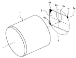
図1は、本実施の形態に係る撮像装置の全体構成を概略的に示す図である。 FIG. 1 is a diagram schematically showing the overall configuration of the image pickup apparatus according to the present embodiment.
図1において、撮像装置100は、撮像対象物に対向するレンズ1と、レンズに対して撮像対象物と反対側に配置された撮像素子2と、撮像素子2で撮像された画像に関する各種処理を行う画像処理部101と、画像処理部101で処理を施された結果としての各種画像やアフィンテーブル等のテーブル、各種変数やその他の情報を記憶する記憶部102とから概略構成されている。
In FIG. 1, an
図8及び図9は、画像処理部における光学歪み補正処理を説明する図であり、図8は光学歪み補正処理に用いるアフィンテーブル作成処理の様子を、図9は光学歪み補正処理の様子をそれぞれ示している。 8 and 9 are diagrams for explaining the optical distortion correction processing in the image processing unit. FIG. 8 shows the affine table creation processing used for the optical distortion correction processing, and FIG. 9 shows the optical distortion correction processing. Showing.
図8において、アフィンテーブル作成処理では、まず、基準の撮像対象物として例えば既知の間隔で作成された格子チャート10を撮像すると、レンズ1による光学歪みを含む画像10aが得られる。画像処理部101では、光学歪みを含む格子チャート10の画像10aに対してアフィン変換を行って光学歪みを補正した画像10bを得ることによりアフィンテーブルを作成する。画像処理部101で作成したアフィンテーブルは記憶部102に記憶される。
In FIG. 8, in the affine table creation process, first, when the
図9において、光学歪み補正処理では、まず、撮像対象物11を撮像し、レンズ1による光学歪みを含む画像11aを取得する。画像処理部101では、記憶部102からアフィンテーブルを読み出し、光学歪みを含む格子チャート10の画像10aに対してアフィンテーブルを使用した光学歪みの補正処理を実施することにより、歪みを大きく低減した撮像対象物11の画像11bを得ることができる。このとき、後述する光軸ズレ量算出処理により得られたレンズ1と撮像素子2の相対位置のズレ量を光学歪み補正処理に適用する(アフィンテーブルをズレ量分オフセットする)ことにより、さらに精度の良い画像11bを得ることができる。
In FIG. 9, in the optical distortion correction process, first, the
図2は、本実施の形態に係る撮像装置のレンズと撮像素子の初期位置における相対的な位置関係を模式的に示す図である。 FIG. 2 is a diagram schematically showing the relative positional relationship between the lens and the image pickup element of the image pickup apparatus according to the present embodiment at the initial positions.
図2に示すように、撮像素子2は初期位置において、レンズ1に対して撮像対象物と反対側に、レンズ1を介して入射される入射光が結像する範囲であるイメージサークル3の外側に位置するケラレ領域4a〜4dを有するように配置されている。ここで、イメージサークル3とは、レンズ1を通った光が結像する光軸1aを中心とする円形の範囲であり、レンズ1の焦点距離や画角により決定される。また、ケラレ領域4a〜4dとは、撮像素子2上におけるイメージサークル3よりも外側に位置する領域であり、レンズ1を介して入射される光が届かない領域である。
As shown in FIG. 2, at the initial position, the
なお、本実施の形態においては、レンズ1と撮像素子2の相対的な初期位置(以下、単に初期位置と称する)におけるケラレ領域4a〜4dが、方形に形成された撮像素子2の4つの角部にそれぞれ位置するように配置される場合を例示している。すなわち、本実施の形態においては、レンズ1により形成されるイメージサークル3の直径が方形に形成された撮像素子2の対角線長よりも小さくなるように、レンズ1及び撮像素子2を構成しており、イメージサークル3と撮像素子2の中心がほぼ一致するように初期位置を設定すると、撮像素子2の4つの角部にケラレ領域4a〜4dが形成される。
In the present embodiment, the
初期位置において、レンズ1の光軸1aが撮像素子2上を通る位置を撮像素子2上の基準位置2aとする。すなわち、初期位置において、撮像素子2の基準位置2aとレンズ1の光軸1aは一致する。なお、撮像素子2の中心と基準位置2aとは必ずしも一致するわけではない。
At the initial position, the position where the
基準位置2aは、画像処理部101において行われる光軸位置算出処理(後に詳述)により算出され、記憶部102に記憶される。光軸位置算出処理は、ケラレ領域4a〜4dの形状に基づいてレンズ1の光軸1aの撮像素子2上の位置を算出する処理である。
The
図3は、撮像装置のレンズと撮像素子の相対位置にズレが生じた場合を示す図である。 FIG. 3 is a diagram showing a case where the relative position between the lens of the image pickup apparatus and the image pickup element is deviated.
図3に示すように、レンズ1と撮像素子2に相対位置のズレが発生した場合、撮像素子2上の基準位置2aとレンズ1の光軸1aの位置、すなわち、イメージサークル3の中心位置とにズレ(光軸ズレ)が生じる。このように、レンズ1と撮像素子2の相対的な位置にズレが生じた後のズレ位置(以下、単にズレ位置と称する)となった場合、撮像素子2上のケラレ領域4e〜4gの形状(場合によっては個数も含む)が初期位置の場合と比較して変化する。本実施の形態では、ズレ位置において光軸位置算出処理を行って撮像素子2上における光軸1aの位置を算出し、初期位置における光軸1aの位置と比較することにより、レンズ1と撮像素子2の相対的な位置のズレ量を算出する(光軸ズレ量算出処理)。
As shown in FIG. 3, when a relative positional deviation occurs between the
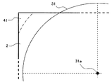
図4及び図5は、画像処理部における光軸位置算出処理の一例を説明する図であり、図4は光軸位置算出処理に用いる仮想円の様子を、図5は光軸位置算出処理の様子をそれぞれ示している。なお、図4及び図5においては、撮像素子2の角部の1つにケラレ領域41が形成された場合を例示して示している。
4 and 5 are diagrams for explaining an example of the optical axis position calculation processing in the image processing unit. FIG. 4 shows a state of a virtual circle used in the optical axis position calculation processing, and FIG. The situation is shown respectively. 4 and 5, the case where the
画像処理部101での光軸位置算出処理は、ケラレ領域4a〜4gの形状に基づいてレンズ1の光軸1aの撮像素子2上の位置を算出する処理である。すなわち、光軸位置算出処理では、レンズ1のイメージサークル3と同径の仮想円31を想定し(図4)、仮想円31とケラレ領域41の外周の円弧形状との一致部分を検出し(図5)、その状態での仮想円31の中心31a位置をズレ位置におけるレンズ1の光軸1aの撮像素子2上の位置として算出され、記憶部102に記憶される。
The optical axis position calculation process in the
また、画像処理部101での光軸ズレ量算出処理では、レンズ1と撮像素子2の初期位置における基準位置2aを記憶部102から読み出し、レンズ1と撮像素子2のズレ位置における光軸1aの位置(イメージサークル3の中心位置)と比較することにより、初期位置に対するズレ位置におけるレンズ1と撮像素子2の相対位置のズレ量を算出する。
Further, in the optical axis shift amount calculation processing in the
以上のように構成した本実施の形態の効果を説明する。 The effects of this embodiment configured as described above will be described.
運転支援システムに用いられる車載カメラ装置は高低音環境下や高湿度環境下などでの使用に対応する必要があり、また、経年によるレンズと撮像素子の位置のズレについても抑制する必要がある。しかしながら、温湿度変化や経年によるレンズと撮像素子の位置のズレを完全に無くすことは不可能であった。 The vehicle-mounted camera device used in the driving support system needs to be used in a high-low sound environment or a high-humidity environment, and it is also necessary to suppress the displacement between the lens and the image sensor due to aging. However, it has been impossible to completely eliminate the positional shift between the lens and the image sensor due to changes in temperature and humidity and aging.
また、レンズには少なからず光学歪みがあり、例えば、一対の撮像装置(ステレオカメラ)で撮像された2つの撮像画像に映し出された対象物に関する水平方向のずれ(視差)を特定し、この特定された視差に基づいて三角測量の原理により対象物までの距離を算出するような技術においては、左右のレンズの光学歪みに偏りが発生していると、対象物までの距離を正確に算出できないばかりか、結果として各撮像装置で撮像した対象物が同一対象物と認識されない状況も考えられる。このため、レンズによる光学歪みを補正する処理を行うが、温湿度変化や経年によってレンズと撮像素子の位置のズレが生じている場合、光学歪みの補正を正確に行うことがでないため、これらの画像を用いた処理の精度が低下してしまうことが考えられる。 Further, the lens has optical distortion to some extent, and for example, the horizontal shift (parallax) of the target object displayed in the two captured images captured by the pair of image capturing devices (stereo cameras) is specified, and this identification is performed. In the technology that calculates the distance to the object by the principle of triangulation based on the disparity that is calculated, if the optical distortion of the left and right lenses is biased, the distance to the object cannot be calculated accurately. Not only that, as a result, it is possible that the objects imaged by the respective imaging devices are not recognized as the same object. For this reason, the process of correcting the optical distortion due to the lens is performed. However, if the position of the lens and the image pickup device is misaligned due to changes in temperature and humidity or aging, it is not possible to correct the optical distortion accurately. It is conceivable that the accuracy of the processing using the image will decrease.
これに対して本実施の形態においては、撮像対象物に対向するレンズ1と、レンズ1に対して撮像対象物と反対側に、レンズ1を介して入射される入射光が結像する範囲であるイメージサークル3の外側に位置するケラレ領域4a〜4dを有するように配置された撮像素子とを備えて構成したので、レンズ1と撮像素子2の位置のズレ量をより正確に把握することができる。すなわち、レンズ1と撮像素子2の相対的な初期位置とレンズ1と撮像素子2の相対的な位置にズレが生じた後のズレ位置とのそれぞれの位置におけるケラレ領域4a〜4gの形状に基づいてレンズ1の光軸の撮像素子2上の位置を算出し、それらの位置を比較することにより、レンズ1と撮像素子2の位置のズレ量をより正確に把握することができる。また、レンズ1と撮像素子2の位置のズレ量をより正確に把握することができるので、光学歪みの補正を正確に行うことができる。また、撮像装置100の作製時におけるレンズ1と撮像素子2との光軸ズレを許容できるとともに、光学歪みの大きさやバラつきの大きさについても許容することができ、撮像装置100の作製コストを抑制することができる。
On the other hand, in the present embodiment, the
なお、本実施の形態においては、撮像素子2の角部の1つに形成されたケラレ領域41に対して光軸位置算出処理を行う例を示したが、これに限られない。ここで、光軸位置算出処理の他の例及びさらに他の例を図6及び図7を参照しつつ説明する。
In the present embodiment, the example in which the optical axis position calculation process is performed on the
図6は、画像処理部における光軸位置算出処理の他の例を説明する図である。 FIG. 6 is a diagram illustrating another example of the optical axis position calculation process in the image processing unit.
図6において、レンズ1と撮像素子2は、レンズ1と撮像素子2の相対的な初期位置におけるケラレ領域42a,42bが方形に形成された撮像素子の4つの角部の少なくとも2つに位置するように配置されている。この場合、画像処理部101は、光軸位置算出処理において、レンズ1のイメージサークル3と同径の仮想円32と、少なくとも2つのケラレ領域42a,42bの外周の円弧形状との一致部分をそれぞれ検出し、少なくとも2つのケラレ領域42a,42bに対応する仮想円32のそれぞれの中心位置(ここでは、説明の簡単のため2つの中心位置を1つの中心位置32aで示している)の平均位置をレンズ1の光軸1aの撮像素子2上の位置として算出する。
In FIG. 6, the
図7は、画像処理部にける光軸位置算出処理のさらに他の例を説明する図である。 FIG. 7 is a diagram illustrating still another example of the optical axis position calculation processing in the image processing unit.
図7において、レンズ1と撮像素子2は、レンズ1と撮像素子2の相対的な初期位置におけるケラレ領域43a〜43dが方形に形成された撮像素子2の4つの角部の少なくとも3つに位置するように配置さている。この場合、画像処理部101は、ケラレ領域43a〜43dのうちの3つのケラレ領域(例えば、ケラレ領域43a〜43c)の外周の円弧形状を直線近似した近似直線5a〜5cとの内接円33を検出し、内接円33の中心位置33aをレンズ1の光軸1aの撮像素子2上の位置として算出する。
In FIG. 7, the
なお、撮像素子2の4つの角部に位置するケラレ領域43a〜43dを用いて光軸位置算出処理を行う場合は、近似直線5a〜5dから3つを選ぶ組合せ数(4C3)から4通りの内接円33が求められるので、こられの内接円33の中心位置33aの平均位置をとれば、さらに正確な光軸1aの位置を算出することができる。
When the optical axis position calculation processing is performed using the
また、本発明は上記した各実施の形態に限定されるものではなく、様々な変形例が含まれる。例えば、上記した実施の形態は本願発明を分かりやすく説明するために詳細に説明したものであり、必ずしも説明した全ての構成を備えるものに限定されるものではない。
また、上記の各構成、機能等は、それらの一部又は全部を、例えば集積回路で設計する等により実現してもよい。また、上記の各構成、機能等は、プロセッサがそれぞれの機能を実現するプログラムを解釈し、実行することによりソフトウェアで実現してもよい。Further, the present invention is not limited to the above-mentioned respective embodiments, but includes various modified examples. For example, the above-described embodiments have been described in detail in order to explain the present invention in an easy-to-understand manner, and are not necessarily limited to those having all the configurations described.
Further, the above-described respective configurations, functions and the like may be realized by partially or entirely designing, for example, an integrated circuit. Further, each of the above-described configurations, functions, and the like may be realized by software by a processor interpreting and executing a program that realizes each function.
1 レンズ、1a 光軸、2 撮像素子、2a 基準位置、3 イメージサークル、4a〜4g ケラレ領域、5a〜5d 近似直線、10 格子チャート、10a,10b 画像、11 撮像対象物、11a,11b 画像、31,32 仮想円、31a 中心、32a,33a 中心位置、33 内接円、41,42a,42b,43a〜43d ケラレ領域、100 撮像装置、101 画像処理部、102 記憶部
DESCRIPTION OF
Claims (6)
前記レンズに対して前記撮像対象物と反対側に、前記レンズを介して入射される入射光が結像する範囲であるイメージサークルの外側に位置するケラレ領域を有するように配置された撮像素子と、
前記レンズと前記撮像素子の相対的な初期位置と前記レンズと前記撮像素子の相対的な位置にズレが生じた後のズレ位置とのそれぞれの位置における前記ケラレ領域の形状に基づいて前記レンズの光軸の前記撮像素子上の位置を算出することにより、前記レンズと前記撮像素子の前記初期位置に対するズレ量を算出する画像処理部と
を備えたことを特徴とする撮像装置。 A lens facing the object to be imaged,
An image pickup element arranged on the side opposite to the image pickup object with respect to the lens so as to have a vignetting region located outside an image circle, which is a range in which incident light incident through the lens forms an image. ,
Based on the shape of the vignetting area at each position of the relative initial position of the lens and the image pickup device and the shift position after the relative position of the lens and the image pickup device has shifted. An image pickup apparatus comprising: an image processing unit that calculates a displacement amount of the lens and the image pickup device with respect to the initial position by calculating a position of an optical axis on the image pickup device.
前記レンズと前記撮像素子は、前記レンズと前記撮像素子の相対的な初期位置における前記ケラレ領域が方形に形成された前記撮像素子の4つの角部に位置するように配置されることを特徴とする撮像装置。 The image pickup apparatus according to claim 1 ,
The lens and the image pickup device are arranged such that the vignetting regions at relative initial positions of the lens and the image pickup device are located at four corners of the image pickup device formed in a rectangular shape. Image pickup device.
前記画像処理部は、前記レンズのイメージサークルと同径の仮想円と前記ケラレ領域の外周の円弧形状との一致部分を検出することにより、前記仮想円の中心位置を前記レンズの光軸の前記撮像素子上の位置として算出することを特徴とする撮像装置。 The imaging device according to claim 1 ,
The image processing unit detects a coincident portion between an imaginary circle having the same diameter as the image circle of the lens and an arc shape of the outer periphery of the vignetting area, and thus the center position of the imaginary circle is set to the optical axis of the lens An image pickup apparatus, which is calculated as a position on an image pickup element.
前記レンズと前記撮像素子は、前記レンズと前記撮像素子の相対的な初期位置における前記ケラレ領域が方形に形成された前記撮像素子の4 つの角部の少なくとも2 つに位置するように配置され、
前記画像処理部は、前記レンズのイメージサークルと同径の仮想円と、前記少なくとも2つの前記ケラレ領域の外周の円弧形状との一致部分をそれぞれ検出し、前記少なくとも2つの前記ケラレ領域に対応する前記仮想円のそれぞれの中心位置の平均位置を前記レンズの光軸の前記撮像素子上の位置として算出することを特徴とする撮像装置。 The imaging device according to claim 1 ,
The lens and the image pickup device are arranged such that the vignetting region at a relative initial position of the lens and the image pickup device is located at least at two corners of the four image pickup devices formed in a rectangular shape,
The image processing unit detects a matching portion between a virtual circle having the same diameter as the image circle of the lens and an arc shape of the outer periphery of the at least two vignetting areas, and corresponds to the at least two vignetting areas. An image pickup apparatus , wherein an average position of respective center positions of the virtual circle is calculated as a position of the optical axis of the lens on the image pickup device .
前記レンズと前記撮像素子は、前記レンズと前記撮像素子の相対的な初期位置における前記ケラレ領域が方形に形成された前記撮像素子の4つの角部の少なくとも3つに位置するように配置され、
前記画像処理部は、前記ケラレ領域のうちの3つのケラレ領域の外周の円弧形状を直線近似した直線との内接円を検出し、前記内接円の中心位置を前記レンズの光軸の前記撮像素子上の位置として算出することを特徴とする撮像装置。 The imaging device according to claim 1 ,
The lens and the image pickup device are arranged such that the vignetting region at a relative initial position of the lens and the image pickup device is located at at least three of four corners of the image pickup device formed in a rectangular shape,
The image processing unit detects an inscribed circle with respect to a straight line obtained by linearly approximating the arc shape of the outer periphery of the three vignetting areas, and sets the center position of the inscribed circle to the optical axis of the lens. An image pickup apparatus, which is calculated as a position on an image pickup element.
前記レンズと前記撮像素子の相対的な初期位置と前記レンズと前記撮像素子の相対的な位置にズレが生じた後のズレ位置とのそれぞれの位置における前記ケラレ領域の形状に基づいて前記レンズの光軸の前記撮像素子上の位置を算出することにより、前記レンズと前記撮像素子の前記初期位置に対するズレ量を算出する手順と
を有することを特徴とする撮像方法。 Imaging is performed on the side opposite to the imaging target with respect to the lens facing the imaging target so as to have a vignetting region located outside an image circle, which is a range in which incident light incident through the lens forms an image. The steps to place the elements,
Based on the shape of the vignetting area at each position of the relative initial position of the lens and the image pickup device and the shift position after the relative position of the lens and the image pickup device has shifted. An image pickup method, comprising: calculating a position of an optical axis on the image pickup device to calculate a shift amount between the lens and the image pickup device with respect to the initial position .
Applications Claiming Priority (3)
| Application Number | Priority Date | Filing Date | Title |
|---|---|---|---|
| JP2016253015 | 2016-12-27 | ||
| JP2016253015 | 2016-12-27 | ||
| PCT/JP2017/045030 WO2018123639A1 (en) | 2016-12-27 | 2017-12-15 | Imaging device and imaging method |
Publications (2)
| Publication Number | Publication Date |
|---|---|
| JPWO2018123639A1 JPWO2018123639A1 (en) | 2019-10-31 |
| JP6727670B2 true JP6727670B2 (en) | 2020-07-22 |
Family
ID=62708068
Family Applications (1)
| Application Number | Title | Priority Date | Filing Date |
|---|---|---|---|
| JP2018559041A Active JP6727670B2 (en) | 2016-12-27 | 2017-12-15 | Imaging device and imaging method |
Country Status (3)
| Country | Link |
|---|---|
| EP (1) | EP3564747B1 (en) |
| JP (1) | JP6727670B2 (en) |
| WO (1) | WO2018123639A1 (en) |
Families Citing this family (2)
| Publication number | Priority date | Publication date | Assignee | Title |
|---|---|---|---|---|
| US11336827B2 (en) | 2017-11-09 | 2022-05-17 | Canon Kabushiki Kaisha | Imaging apparatus and interchangeable lens apparatus that utilize image circle information of an imaging optical system in the interchangeable lens apparatus |
| US20220274526A1 (en) | 2019-07-10 | 2022-09-01 | Sony Semiconductor Solutions Corporation | Abnormality detection device, abnormality detection method, program, and information processing system |
Family Cites Families (5)
| Publication number | Priority date | Publication date | Assignee | Title |
|---|---|---|---|---|
| CN101015197B (en) * | 2004-06-07 | 2010-10-27 | 诺基亚公司 | Method and apparatus for improving image quality |
| US20070211154A1 (en) * | 2006-03-13 | 2007-09-13 | Hesham Mahmoud | Lens vignetting correction algorithm in digital cameras |
| JP2012165206A (en) * | 2011-02-07 | 2012-08-30 | Jvc Kenwood Corp | Setting method of effective pixel region of solid state image sensor and manufacturing method of imaging apparatus |
| JP2013038620A (en) * | 2011-08-09 | 2013-02-21 | Ricoh Co Ltd | Area sensor position adjustment method |
| JP2014135567A (en) | 2013-01-08 | 2014-07-24 | Hitachi Ltd | Imaging apparatus and imaging method |
-
2017
- 2017-12-15 WO PCT/JP2017/045030 patent/WO2018123639A1/en unknown
- 2017-12-15 EP EP17886079.7A patent/EP3564747B1/en active Active
- 2017-12-15 JP JP2018559041A patent/JP6727670B2/en active Active
Also Published As
| Publication number | Publication date |
|---|---|
| EP3564747B1 (en) | 2021-10-27 |
| WO2018123639A1 (en) | 2018-07-05 |
| EP3564747A4 (en) | 2020-08-05 |
| JPWO2018123639A1 (en) | 2019-10-31 |
| EP3564747A1 (en) | 2019-11-06 |
Similar Documents
| Publication | Publication Date | Title |
|---|---|---|
| KR101787304B1 (en) | Calibration method, calibration device, and computer program product | |
| US8619144B1 (en) | Automatic camera calibration | |
| US8593536B2 (en) | Image pickup apparatus with calibration function | |
| US20200177866A1 (en) | Calibration apparatus, chart for calibration, chart pattern generation apparatus, and calibration method | |
| TW201515433A (en) | Image calibration system and calibration method of a stereo camera | |
| JP5365387B2 (en) | Position detection device | |
| JP2003254748A (en) | Stereo image characteristic inspection system | |
| TWI761684B (en) | Calibration method of an image device and related image device and operational device thereof | |
| US10821911B2 (en) | Method and system of camera focus for advanced driver assistance system (ADAS) | |
| JPWO2008053649A1 (en) | Wide-angle image acquisition method and wide-angle stereo camera device | |
| JP6727670B2 (en) | Imaging device and imaging method | |
| JP4260129B2 (en) | Compound eye photographing apparatus and adjustment method thereof | |
| JP2011149931A (en) | Distance image acquisition device | |
| JP2008045983A (en) | Adjustment device for stereo camera | |
| JP5375531B2 (en) | Distance image acquisition device and distance image acquisition processing method | |
| CN110136205B (en) | Parallax calibration method, device and system of multi-view camera | |
| JP3666348B2 (en) | Distance recognition device | |
| JP2011147079A (en) | Image pickup device | |
| TWI526993B (en) | Method of image correction and image capturing device thereof | |
| JP3599255B2 (en) | Environment recognition device for vehicles | |
| JP2008288869A (en) | Calibration device, and calibrating method and program | |
| JP2019168479A (en) | Controller, imaging device, method for control, program, and, and storage medium | |
| JP2008241609A (en) | Distance measuring system and distance measuring method | |
| JP6241083B2 (en) | Imaging apparatus and parallax detection method | |
| WO2021145280A1 (en) | Robot system |
Legal Events
| Date | Code | Title | Description |
|---|---|---|---|
| A621 | Written request for application examination |
Free format text: JAPANESE INTERMEDIATE CODE: A621 Effective date: 20190520 |
|
| A131 | Notification of reasons for refusal |
Free format text: JAPANESE INTERMEDIATE CODE: A131 Effective date: 20200414 |
|
| A521 | Request for written amendment filed |
Free format text: JAPANESE INTERMEDIATE CODE: A523 Effective date: 20200520 |
|
| TRDD | Decision of grant or rejection written | ||
| A01 | Written decision to grant a patent or to grant a registration (utility model) |
Free format text: JAPANESE INTERMEDIATE CODE: A01 Effective date: 20200609 |
|
| A61 | First payment of annual fees (during grant procedure) |
Free format text: JAPANESE INTERMEDIATE CODE: A61 Effective date: 20200626 |
|
| R150 | Certificate of patent or registration of utility model |
Ref document number: 6727670 Country of ref document: JP Free format text: JAPANESE INTERMEDIATE CODE: R150 |
|
| S533 | Written request for registration of change of name |
Free format text: JAPANESE INTERMEDIATE CODE: R313533 |
|
| R350 | Written notification of registration of transfer |
Free format text: JAPANESE INTERMEDIATE CODE: R350 |