JP6722860B2 - Adsorption refrigerator, method for controlling adsorption refrigerator and cooling system - Google Patents
Adsorption refrigerator, method for controlling adsorption refrigerator and cooling system Download PDFInfo
- Publication number
- JP6722860B2 JP6722860B2 JP2017194449A JP2017194449A JP6722860B2 JP 6722860 B2 JP6722860 B2 JP 6722860B2 JP 2017194449 A JP2017194449 A JP 2017194449A JP 2017194449 A JP2017194449 A JP 2017194449A JP 6722860 B2 JP6722860 B2 JP 6722860B2
- Authority
- JP
- Japan
- Prior art keywords
- adsorber
- outlet
- inlet
- heat
- heat medium
- Prior art date
- Legal status (The legal status is an assumption and is not a legal conclusion. Google has not performed a legal analysis and makes no representation as to the accuracy of the status listed.)
- Active
Links
Images


Classifications
-
- F—MECHANICAL ENGINEERING; LIGHTING; HEATING; WEAPONS; BLASTING
- F25—REFRIGERATION OR COOLING; COMBINED HEATING AND REFRIGERATION SYSTEMS; HEAT PUMP SYSTEMS; MANUFACTURE OR STORAGE OF ICE; LIQUEFACTION SOLIDIFICATION OF GASES
- F25B—REFRIGERATION MACHINES, PLANTS OR SYSTEMS; COMBINED HEATING AND REFRIGERATION SYSTEMS; HEAT PUMP SYSTEMS
- F25B17/00—Sorption machines, plants or systems, operating intermittently, e.g. absorption or adsorption type
- F25B17/08—Sorption machines, plants or systems, operating intermittently, e.g. absorption or adsorption type the absorbent or adsorbent being a solid, e.g. salt
-
- F—MECHANICAL ENGINEERING; LIGHTING; HEATING; WEAPONS; BLASTING
- F25—REFRIGERATION OR COOLING; COMBINED HEATING AND REFRIGERATION SYSTEMS; HEAT PUMP SYSTEMS; MANUFACTURE OR STORAGE OF ICE; LIQUEFACTION SOLIDIFICATION OF GASES
- F25B—REFRIGERATION MACHINES, PLANTS OR SYSTEMS; COMBINED HEATING AND REFRIGERATION SYSTEMS; HEAT PUMP SYSTEMS
- F25B41/00—Fluid-circulation arrangements
- F25B41/20—Disposition of valves, e.g. of on-off valves or flow control valves
- F25B41/28—Disposition of valves, e.g. of on-off valves or flow control valves specially adapted for sorption cycles
-
- F—MECHANICAL ENGINEERING; LIGHTING; HEATING; WEAPONS; BLASTING
- F25—REFRIGERATION OR COOLING; COMBINED HEATING AND REFRIGERATION SYSTEMS; HEAT PUMP SYSTEMS; MANUFACTURE OR STORAGE OF ICE; LIQUEFACTION SOLIDIFICATION OF GASES
- F25B—REFRIGERATION MACHINES, PLANTS OR SYSTEMS; COMBINED HEATING AND REFRIGERATION SYSTEMS; HEAT PUMP SYSTEMS
- F25B15/00—Sorption machines, plants or systems, operating continuously, e.g. absorption type
- F25B15/02—Sorption machines, plants or systems, operating continuously, e.g. absorption type without inert gas
- F25B15/025—Liquid transfer means
-
- F—MECHANICAL ENGINEERING; LIGHTING; HEATING; WEAPONS; BLASTING
- F25—REFRIGERATION OR COOLING; COMBINED HEATING AND REFRIGERATION SYSTEMS; HEAT PUMP SYSTEMS; MANUFACTURE OR STORAGE OF ICE; LIQUEFACTION SOLIDIFICATION OF GASES
- F25B—REFRIGERATION MACHINES, PLANTS OR SYSTEMS; COMBINED HEATING AND REFRIGERATION SYSTEMS; HEAT PUMP SYSTEMS
- F25B17/00—Sorption machines, plants or systems, operating intermittently, e.g. absorption or adsorption type
- F25B17/08—Sorption machines, plants or systems, operating intermittently, e.g. absorption or adsorption type the absorbent or adsorbent being a solid, e.g. salt
- F25B17/083—Sorption machines, plants or systems, operating intermittently, e.g. absorption or adsorption type the absorbent or adsorbent being a solid, e.g. salt with two or more boiler-sorbers operating alternately
-
- F—MECHANICAL ENGINEERING; LIGHTING; HEATING; WEAPONS; BLASTING
- F25—REFRIGERATION OR COOLING; COMBINED HEATING AND REFRIGERATION SYSTEMS; HEAT PUMP SYSTEMS; MANUFACTURE OR STORAGE OF ICE; LIQUEFACTION SOLIDIFICATION OF GASES
- F25B—REFRIGERATION MACHINES, PLANTS OR SYSTEMS; COMBINED HEATING AND REFRIGERATION SYSTEMS; HEAT PUMP SYSTEMS
- F25B17/00—Sorption machines, plants or systems, operating intermittently, e.g. absorption or adsorption type
- F25B17/08—Sorption machines, plants or systems, operating intermittently, e.g. absorption or adsorption type the absorbent or adsorbent being a solid, e.g. salt
- F25B17/086—Sorption machines, plants or systems, operating intermittently, e.g. absorption or adsorption type the absorbent or adsorbent being a solid, e.g. salt with two or more boiler-sorber/evaporator units
-
- F—MECHANICAL ENGINEERING; LIGHTING; HEATING; WEAPONS; BLASTING
- F25—REFRIGERATION OR COOLING; COMBINED HEATING AND REFRIGERATION SYSTEMS; HEAT PUMP SYSTEMS; MANUFACTURE OR STORAGE OF ICE; LIQUEFACTION SOLIDIFICATION OF GASES
- F25B—REFRIGERATION MACHINES, PLANTS OR SYSTEMS; COMBINED HEATING AND REFRIGERATION SYSTEMS; HEAT PUMP SYSTEMS
- F25B25/00—Machines, plants or systems, using a combination of modes of operation covered by two or more of the groups F25B1/00 - F25B23/00
- F25B25/005—Machines, plants or systems, using a combination of modes of operation covered by two or more of the groups F25B1/00 - F25B23/00 using primary and secondary systems
-
- F—MECHANICAL ENGINEERING; LIGHTING; HEATING; WEAPONS; BLASTING
- F25—REFRIGERATION OR COOLING; COMBINED HEATING AND REFRIGERATION SYSTEMS; HEAT PUMP SYSTEMS; MANUFACTURE OR STORAGE OF ICE; LIQUEFACTION SOLIDIFICATION OF GASES
- F25B—REFRIGERATION MACHINES, PLANTS OR SYSTEMS; COMBINED HEATING AND REFRIGERATION SYSTEMS; HEAT PUMP SYSTEMS
- F25B49/00—Arrangement or mounting of control or safety devices
- F25B49/04—Arrangement or mounting of control or safety devices for sorption type machines, plants or systems
- F25B49/043—Operating continuously
-
- F—MECHANICAL ENGINEERING; LIGHTING; HEATING; WEAPONS; BLASTING
- F25—REFRIGERATION OR COOLING; COMBINED HEATING AND REFRIGERATION SYSTEMS; HEAT PUMP SYSTEMS; MANUFACTURE OR STORAGE OF ICE; LIQUEFACTION SOLIDIFICATION OF GASES
- F25B—REFRIGERATION MACHINES, PLANTS OR SYSTEMS; COMBINED HEATING AND REFRIGERATION SYSTEMS; HEAT PUMP SYSTEMS
- F25B49/00—Arrangement or mounting of control or safety devices
- F25B49/04—Arrangement or mounting of control or safety devices for sorption type machines, plants or systems
- F25B49/046—Operating intermittently
-
- F—MECHANICAL ENGINEERING; LIGHTING; HEATING; WEAPONS; BLASTING
- F25—REFRIGERATION OR COOLING; COMBINED HEATING AND REFRIGERATION SYSTEMS; HEAT PUMP SYSTEMS; MANUFACTURE OR STORAGE OF ICE; LIQUEFACTION SOLIDIFICATION OF GASES
- F25B—REFRIGERATION MACHINES, PLANTS OR SYSTEMS; COMBINED HEATING AND REFRIGERATION SYSTEMS; HEAT PUMP SYSTEMS
- F25B2315/00—Sorption refrigeration cycles or details thereof
- F25B2315/005—Regeneration
-
- F—MECHANICAL ENGINEERING; LIGHTING; HEATING; WEAPONS; BLASTING
- F25—REFRIGERATION OR COOLING; COMBINED HEATING AND REFRIGERATION SYSTEMS; HEAT PUMP SYSTEMS; MANUFACTURE OR STORAGE OF ICE; LIQUEFACTION SOLIDIFICATION OF GASES
- F25B—REFRIGERATION MACHINES, PLANTS OR SYSTEMS; COMBINED HEATING AND REFRIGERATION SYSTEMS; HEAT PUMP SYSTEMS
- F25B2315/00—Sorption refrigeration cycles or details thereof
- F25B2315/007—Parallel systems therefor
-
- F—MECHANICAL ENGINEERING; LIGHTING; HEATING; WEAPONS; BLASTING
- F25—REFRIGERATION OR COOLING; COMBINED HEATING AND REFRIGERATION SYSTEMS; HEAT PUMP SYSTEMS; MANUFACTURE OR STORAGE OF ICE; LIQUEFACTION SOLIDIFICATION OF GASES
- F25B—REFRIGERATION MACHINES, PLANTS OR SYSTEMS; COMBINED HEATING AND REFRIGERATION SYSTEMS; HEAT PUMP SYSTEMS
- F25B2339/00—Details of evaporators; Details of condensers
- F25B2339/04—Details of condensers
- F25B2339/047—Water-cooled condensers
-
- Y—GENERAL TAGGING OF NEW TECHNOLOGICAL DEVELOPMENTS; GENERAL TAGGING OF CROSS-SECTIONAL TECHNOLOGIES SPANNING OVER SEVERAL SECTIONS OF THE IPC; TECHNICAL SUBJECTS COVERED BY FORMER USPC CROSS-REFERENCE ART COLLECTIONS [XRACs] AND DIGESTS
- Y02—TECHNOLOGIES OR APPLICATIONS FOR MITIGATION OR ADAPTATION AGAINST CLIMATE CHANGE
- Y02A—TECHNOLOGIES FOR ADAPTATION TO CLIMATE CHANGE
- Y02A30/00—Adapting or protecting infrastructure or their operation
- Y02A30/27—Relating to heating, ventilation or air conditioning [HVAC] technologies
-
- Y—GENERAL TAGGING OF NEW TECHNOLOGICAL DEVELOPMENTS; GENERAL TAGGING OF CROSS-SECTIONAL TECHNOLOGIES SPANNING OVER SEVERAL SECTIONS OF THE IPC; TECHNICAL SUBJECTS COVERED BY FORMER USPC CROSS-REFERENCE ART COLLECTIONS [XRACs] AND DIGESTS
- Y02—TECHNOLOGIES OR APPLICATIONS FOR MITIGATION OR ADAPTATION AGAINST CLIMATE CHANGE
- Y02B—CLIMATE CHANGE MITIGATION TECHNOLOGIES RELATED TO BUILDINGS, e.g. HOUSING, HOUSE APPLIANCES OR RELATED END-USER APPLICATIONS
- Y02B30/00—Energy efficient heating, ventilation or air conditioning [HVAC]
- Y02B30/62—Absorption based systems
Landscapes
- Engineering & Computer Science (AREA)
- Physics & Mathematics (AREA)
- Mechanical Engineering (AREA)
- Thermal Sciences (AREA)
- General Engineering & Computer Science (AREA)
- Sorption Type Refrigeration Machines (AREA)
Description
本開示は吸着冷凍機、吸着冷凍機を制御する方法および冷却システムに関する。 The present disclosure relates to adsorption refrigerators, methods for controlling adsorption refrigerators, and cooling systems.
熱式ヒートポンプとして、吸着冷凍機が知られている。吸着冷凍機では、吸着器の容器内に吸着材と呼ばれる材料(例えば、シリカゲル、ゼオライトなどの多孔質材料)が設けられている。この吸着材冷媒である水を吸着・脱着する、すなわちコンプレッサー動作を行うことで冷媒を温度勾配に逆らって移動し、ヒートポンプ作用を奏する。 An adsorption refrigerator is known as a thermal heat pump. In an adsorption refrigerator, a material called an adsorbent (for example, a porous material such as silica gel or zeolite) is provided in the container of the adsorber. By adsorbing and desorbing water which is the adsorbent refrigerant, that is, by performing a compressor operation, the refrigerant moves against the temperature gradient and a heat pump action is achieved.
なお、この吸着器の吸着工程では、容器内は適宜の真空ポンプで減圧状態に制御されているので、低温(例えば、約6℃程度)の蒸気が蒸発器より吸着材に吸着される。また、吸着器の吸着工程では、吸着材が蒸気を吸着すると発熱するので、適宜の熱交換器(例えば、冷却塔)からの冷却水により吸着材の熱が除去される。これにより、吸着材は、その吸着性能に適した温度に維持される。 In the adsorption process of this adsorber, since the inside of the container is controlled to a depressurized state by an appropriate vacuum pump, low-temperature (for example, about 6° C.) vapor is adsorbed by the adsorbent from the evaporator. Further, in the adsorption step of the adsorber, heat is generated when the adsorbent adsorbs vapor, so that the heat of the adsorbent is removed by cooling water from an appropriate heat exchanger (for example, a cooling tower). As a result, the adsorbent is maintained at a temperature suitable for its adsorption performance.
吸着材が乾燥している間は蒸気の吸着が行われるが、やがて、吸着材が水蒸気飽和して蒸気の吸着が止まり、吸着材の再生(回復)が必要となる。 Vapor is adsorbed while the adsorbent is dry, but eventually, the adsorbent is saturated with water vapor and adsorption of vapor is stopped, and regeneration (recovery) of the adsorbent is required.
この吸着器の再生工程では、吸着材が適宜の外部熱源の熱により加熱される。吸着材の加熱により、吸着材が温度上昇すると、吸着材に付着した水分の脱離(脱着)が起こり、吸着材の吸着性能が回復する。吸着材から離脱した蒸気は、凝縮器内で冷却水との熱交換で冷やされ、液体の水として凝縮器に戻される。 In the adsorber regeneration step, the adsorbent is heated by heat from an appropriate external heat source. When the temperature of the adsorbent rises due to the heating of the adsorbent, the water adhering to the adsorbent is desorbed (desorbed), and the adsorption performance of the adsorbent is restored. The vapor separated from the adsorbent is cooled by heat exchange with cooling water in the condenser and returned to the condenser as liquid water.
このように、吸着冷凍機の吸着器では、吸着材の蒸気吸着および再生が交互に行われる。 As described above, in the adsorption device of the adsorption refrigerator, vapor adsorption and regeneration of the adsorbent are alternately performed.
そして、従来の単効用吸着冷凍機は、一般的に、かかる吸着器が対をなして設けられており、一方の吸着器で吸着工程を行う際に、他方の吸着器で再生工程を行うようにし、これを適時に切り替えて、冷凍出力を連続的に生成するように構成されている。 And, in the conventional single-effect adsorption refrigerator, such an adsorber is generally provided as a pair, and when one adsorber performs the adsorption step, the other adsorber performs the regeneration step. The refrigerating output is continuously generated by switching this timely.
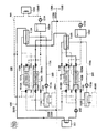
以下、図面を参照しながら、かかる単効用吸着冷凍機の構成および動作を説明する。図1および図2は、従来の単効用吸着冷凍機の一例を示す図である。 Hereinafter, the configuration and operation of the single-effect adsorption refrigerator will be described with reference to the drawings. 1 and 2 are diagrams showing an example of a conventional single-effect adsorption refrigerator.
単効用吸着冷凍機100は、一対の吸着器101、102(以下、吸着器ペア101、102という)と、冷媒系統300と、温熱系統400と、冷却水系統500と、を備える。
The single-
吸着器ペア101、102はそれぞれ、シリカゲル、ゼオライトなどの吸着材が容器に充填されている。なお、吸着器ペア101、102内は、ここでは、図示しない真空ポンプにより、1/100気圧程度に減圧されている。
Each of the
吸着器ペア101、102のそれぞれには、これらの吸着材との間で熱交換が行われる熱媒体(例えば、水など)が流れる流路部材が通過している。つまり、この流路部材が、熱交換フィン、熱交換コイルなどの熱交換部材を備える。
A flow path member through which a heat medium (for example, water) that performs heat exchange with these adsorbents flows is passing through each of the
吸着器101の流路部材の出口および入口の付近には、温熱系統400の循環経路120を循環する高温の温熱媒体を適時に吸着器101に供給し得るとともに、冷却水系統500の循環経路130を循環する冷却水を適時に吸着器101に供給し得るように、三方弁121、123が設けられている。つまり、吸着器101の出口および入口がそれぞれ、三方弁123、121のそれぞれを介して温熱系統400および冷却水系統500の両方に接続されている。よって、単効用吸着冷凍機100は、吸着器101内に、温熱媒体を通過させるか、冷却水を通過させるか選択できるように構成されている。
In the vicinity of the outlet and the inlet of the flow path member of the
また、吸着器102の流路部材の出口および入口の付近には、温熱系統400の循環経路120を循環する高温の温熱媒体を適時に吸着器102に供給し得るとともに、冷却水系統500の循環経路130を循環する低温の冷却水を適時に吸着器102に供給し得るように、三方弁122、124が設けられている。つまり、吸着器102の出口および入口がそれぞれ、三方弁124、122のそれぞれを介して温熱系統400および冷却水系統500の両方に接続されている。よって、単効用吸着冷凍機100は、吸着器102内に、温熱媒体を通過させるか、冷却水を通過させるか選択できるように構成されている。
In addition, near the outlet and the inlet of the flow path member of the
なお、三方弁121、122、123、124として、例えば、電磁式のボールバルブを用いることができる。
As the three-
さらに、吸着器ペア101、102はそれぞれ、二方弁111、112のそれぞれを介して蒸発器115に接続するとともに、二方弁113、114のそれぞれを介して凝縮器116にも接続している。
Further, each of the
なお、二方弁111、112、113、114として、例えば、電磁式または空圧式のバタフライバルブを用いることができる。
As the two-
ここで、図1では、吸着器101で吸着工程が行われ、吸着器102で再生工程が行われている状態が図示されている。図2では、吸着器101で再生工程が行われ、吸着器102で吸着工程が行われている状態が図示されている。つまり、吸着器ペア101、102は、温熱媒体による加熱および冷却水による冷却が交互に行われる。
Here, FIG. 1 illustrates a state in which the adsorption process is performed in the
そこで、図1および図2において、図面の内容が理解しやすくなるよう、便宜上、三方弁121、122、123、124の開放側が黒で図示され、閉止側が白で図示されている。また、開放状態の二方弁111、112、113、114は黒で図示され、閉止状態の二方弁111、112、113、114は白で図示されている。また、連通状態の循環経路130および吸着材に吸着される蒸気の経路を実線で表し、連通状態の循環経路120および再生蒸気の経路を点線で表し、熱媒体が流れていない非連通状態の経路を細い二点鎖線で表している。
Therefore, in FIGS. 1 and 2, for convenience of understanding of the drawings, the open sides of the three-
以下、図1を用いて、吸着器101で吸着工程が行われ、吸着器102で再生工程が行われている場合の単効用吸着冷凍機100についてさらに詳しく説明する。なお、図2の単効用吸着冷凍機100については、以下の説明で容易に理解できるので説明を省略する。また、単効用吸着冷凍機100の冷媒系統300、温熱系統400の温熱媒体には、通常、水が使用される。よって、温熱媒体を水として、単効用吸着冷凍機100の構成および動作を説明する。
Hereinafter, the single-
冷媒系統300、温熱系統400および冷却水系統500の水温は系統毎に相違している。一例として、冷媒系統300の水温は、約15℃程度であり、温熱系統400の水温は、約80℃程度であり、冷却水系統500の水温は、約30℃程度である。
The water temperatures of the
冷媒系統300の水経路110の両端はそれぞれ、蒸発器115および凝縮器116に接続されている。
Both ends of the
蒸発器115では、蒸発器115内の水が蒸発することで冷凍出力が取り出される。つまり、蒸発器115から、水蒸発により冷却された冷水を外部へ送ることができる。
In the
本例では、二方弁111が開放され、二方弁112が閉止されているので、蒸発器115で発生した蒸気は、吸着器101の吸着材に吸着される。
In this example, since the two-
凝縮器116では、再生工程で発生した蒸気が、冷却水系統500の循環経路130を流れる循環水により冷却される。これにより、凝縮器116内で、凝縮水が発生し、この凝縮水が、ポンプ117の動力により上記の蒸発器115へと送られ、蒸発を行うための水として再利用される。本例では、二方弁113が閉止され、二方弁114が開放されているので、吸着器102の再生工程で発生した蒸気が、凝縮器116へ供給されている。
In the
なお、ポンプ117として、例えば、マグネットポンプ、カスケードポンプなどを用いることができる。
As the
温熱系統400の循環経路120上には、熱源熱交換器125、吸着器102、バッファータンク126およびポンプ127が、循環水が流れる方向において、この順に配されている。この熱源熱交換器125では、循環経路120を流れる循環水が受熱流体に用いられているので、適宜の熱源から温熱系統400に熱を取り込み得る(つまり、循環経路120を流れる循環水が加熱される)。本例では、三方弁121、122、123、124の弁操作およびポンプ127の動力により、熱源熱交換器125を通過した後の循環経路120内の高温の循環水は、吸着器102内へと送られる。これにより、吸着器102の吸着材が、高温の循環水との熱交換により加熱され、吸着器102の再生工程が行われる。
The heat
なお、ポンプ127として、例えば、マグネットポンプ、カスケードポンプなどを用いることができる。また、バッファータンク126は、温水を一時的に貯蔵するバッファー用のタンクである。
As the
冷却水系統500の循環経路130上には、熱交換器131(例えば、冷却塔)、ポンプ132、吸着器101および凝縮器116が、循環水が流れる方向において、この順に配されている。熱交換器131では、循環経路130を流れる循環水が加熱流体に用いられているので、循環経路130内の循環水が熱交換器131を通過するとき、循環水から熱が除去される(つまり、循環経路130を流れる循環水が冷却される)。本例では、三方弁121、122、123、124の弁操作およびポンプ132の動力により、熱交換器131を通過した後の循環経路130内の低温の循環水は、吸着器101内へと送られる。これにより、吸着器101の吸着材が、低温の循環水との熱交換により冷却され、吸着工程に適した温度に維持される。吸着器101内を通過した循環水は、上記の凝縮器116において、再生工程で発生した蒸気を冷却するのに使用される。
On the
なお、ポンプ132として、例えば、マグネットポンプ、カスケードポンプなどを用いることができる。
As the
このようにして、単効用吸着冷凍機100は、一方の吸着器101で吸着工程を行う際に、他方の吸着器102で再生工程を行うようにし、これを適時に切り替えて、冷凍出力を連続的に生成している。
In this way, in the single-
なお、上記切り替えは、例えば、予めサイクルタイムを固定する方式でも良いし、吸着器ペア101、102のそれぞれの温度に基づいて制御する方式でも良い。後者の場合、吸着器101の流路部材の出口付近および入口付近のそれぞれに、一対の温度検知器(図示せず)を設け、吸着器102の流路部材の出口付近および入口付近のそれぞれにも、一対の温度検知器(図示せず)を設けると良い。つまり、一対の温度検知器のそれぞれの検知温度の差(以下、検知温度差)から吸着器ペア101、102の吸着工程の状態および再生工程の状態を知ることができる。例えば、吸着材の蒸気吸着が完全に止まった場合、吸着材が完全に再生された場合、検知温度差が理論上ゼロになる。
The switching may be performed by, for example, fixing the cycle time in advance or by controlling based on the temperature of each of the adsorber pairs 101 and 102. In the latter case, a pair of temperature detectors (not shown) are provided near the outlet and the inlet of the flow path member of the
次に、吸着冷凍機の二重効用化(Double-Effect)について説明する。熱式ヒートポンプにおいて、動作温度が高い側の第1吸着冷凍サイクルから得られる排熱を利用することで、動作温度が低い側の第2吸着冷凍サイクルを駆動する方式を、冷凍サイクルの二重効用化と呼ぶ。 Next, double-effect of the adsorption refrigerator will be described. In the heat type heat pump, the exhaust heat obtained from the first adsorption refrigeration cycle on the side with a high operating temperature is used to drive the second adsorption refrigeration cycle on the side with a low operating temperature. Called.
例えば、吸収冷凍機においては、高温再生器から得られる高温の再生蒸気の凝縮熱により低温再生器の再生を行う凝縮熱回収方式の二重効用サイクルが一般的に知られている。この場合、二重効用サイクルの成績係数(COP)は、以下の(式1)の理論式により計算される。 For example, in an absorption refrigerator, a double-effect cycle of a condensation heat recovery system is generally known in which the low temperature regenerator is regenerated by the condensation heat of high temperature regenerated steam obtained from the high temperature regenerator. In this case, the coefficient of performance (COP) of the double-effect cycle is calculated by the following theoretical formula (Formula 1).
(式1) ε0=ε1+(ε1×ε2)=ε1×(1+ε2)
(式1)において、ε0は、二重効用サイクルのCOP、ε1は、第1冷凍サイクルの単効用COP、ε2は、第2冷凍サイクルの単効用COPである。
(Equation 1) ε0=ε1+(ε1×ε2)=ε1×(1+ε2)
In (Equation 1), ε0 is a double-effect cycle COP, ε1 is a single-effect COP of the first refrigeration cycle, and ε2 is a single-effect COP of the second refrigeration cycle.
ここで、単効用吸収冷凍機のCOPはおよそ0.6であるので、第1冷凍サイクル、第2冷凍サイクルの単効用COPがともに0.6である場合には、これを(式1)に代入すると、ε0=0.96と計算される。すなわち、二重効用サイクルは、単効用サイクルに比べて約60%もCOPが向上する。 Here, since the COP of the single-effect absorption refrigerator is approximately 0.6, when both the single-effect COP of the first refrigeration cycle and the second refrigeration cycle are 0.6, this is set to (Equation 1). By substituting, ε0=0.96 is calculated. That is, the COP of the double-effect cycle is improved by about 60% as compared with the single-effect cycle.
上記の吸収冷凍機と同様、吸着冷凍機でも二重効用サイクルが適用可能であることは公知である。なお、この吸着冷凍機では、上記の凝縮熱回収方式による二重効用化の他、吸着熱回収方式による二重効用化が可能である(例えば、非特許文献1参照)。 It is known that the double effect cycle can be applied to the adsorption refrigerator as well as the absorption refrigerator described above. In addition, in this adsorption refrigeration machine, in addition to the double effect by the condensation heat recovery method, the double effect by the adsorption heat recovery method is possible (for example, see Non-Patent Document 1).
そして、非特許文献1では、吸着材の適切な選択により、吸着熱回収方式による二重効用化の方が、凝縮熱回収方式による二重効用化に比べて高効率化が図れることが開示されている。
Then, in
なお、吸着熱とは、吸着冷凍機の吸着器の吸着工程において、吸着材の蒸気吸着に伴って発生する熱である。つまり、吸着熱は、吸着器に吸引された水蒸気が吸着材に吸着されることで、運動エネルギーを失う結果として発生する熱であって、熱量的には、吸着器の再生工程で発生する凝縮熱と等しい。この吸着熱を熱媒体により回収して、熱媒体で回収された熱により第2吸着冷凍サイクルを再生駆動する方式が吸着熱回収方式による二重効用化である。 The heat of adsorption is the heat generated by the vapor adsorption of the adsorbent in the adsorption step of the adsorber of the adsorption refrigerator. That is, the heat of adsorption is the heat generated as a result of the loss of kinetic energy due to the water vapor sucked in the adsorber being adsorbed by the adsorbent, and in terms of calorific value, it is the condensation generated in the regeneration process of the adsorber. Equal to heat. The method of recovering the heat of adsorption by the heat medium and regeneratingly driving the second adsorption refrigeration cycle by the heat recovered by the heat medium is the double effect of the adsorption heat recovery method.
非特許文献1には、吸着器の吸着材として、シリカゲルおよびシリカゲルの組合せを用いる場合、約120℃程度の排熱によりCOPが約1.0程度の二重効用吸着冷凍機を実現可能であることが開示されている。また、吸着材として、三菱樹脂株式会社から上市されている吸着材アクソア「AQSOR(登録商標)-Z02およびAQSOR(登録商標)-Z01」の組合せを用いる場合、約90℃程度の排熱によりCOPが約1.0程度の二重効用吸着冷凍機を実現可能であることが開示されている。
In
しかしながら、非特許文献1は、吸着熱回収方式による二重効用化の動作原理を記載するに過ぎず、このような吸着冷凍機の具体的な構成要素は開示されていない。
However,
本開示の一態様(aspect)は、このような事情に鑑みてなされたものであり、吸着熱回収方式による二重効用化のための具体的な構成要素を具備する吸着冷凍機を提供する。また、本開示の一態様は、このような吸着冷凍機を制御する方法を提供する。また、本開示の一態様は、このような吸着冷凍機を備える冷却システムを提供する。 One aspect (aspect) of the present disclosure has been made in view of such circumstances, and provides an adsorption refrigerating machine including specific constituent elements for dual effect by an adsorption heat recovery system. Moreover, one aspect of the present disclosure provides a method for controlling such an adsorption refrigerator. Moreover, one aspect of the present disclosure provides a cooling system including such an adsorption refrigerator.
本開示の一態様の吸着冷凍機は、以下を具備する:
第1吸着材冷媒を吸着および脱着する第1吸着材を内部に備えた第1吸着器、
前記第1吸着材冷媒を吸着および脱着する第2吸着材を内部に備えた第2吸着器、
減圧下で前記第1吸着材冷媒を蒸発させて第1作動流体を冷却する第1蒸発器、
気体状態の前記第1吸着材冷媒を凝縮させる第1凝縮器、
第2吸着材冷媒を吸着および脱着する第3吸着材を内部に備えた第3吸着器、
前記第2吸着材冷媒を吸着および脱着する第4吸着材を内部に備えた第4吸着器、
減圧下で前記第2吸着材冷媒を蒸発させて第2作動流体を冷却する第2蒸発器、
気体状態の前記第2吸着材冷媒を凝縮させる第2凝縮器、
第1熱媒体に第1熱源から吸収された熱を与える第1熱交換器、
第2熱媒体から熱を除去して放出する第2熱交換器、
第1の状態、第2の状態、第3の状態および第4の状態のいずれかに切り替える制御を行う制御部、ここで、
前記第1の状態において、
前記第1蒸発器は前記第1吸着器に接続され、
前記第2蒸発器は前記第3吸着器に接続され、
前記制御部は、前記第2吸着器の流入口を前記第1熱交換器の流出口に、前記第2吸着器の流出口を前記第1熱交換器の流入口にそれぞれ接続して第1循環経路を形成し、
前記第1熱交換器の流出口から流出した前記第1熱媒体は、前記第2吸着器の流入口に流入し、
前記第2吸着器において、前記第1熱交換器によって加熱された前記第1熱媒体の熱によって、前記第2吸着材に吸着された前記第1吸着材冷媒が脱着され、
前記第2吸着器の流出口から流出した前記第1熱媒体は、前記第1熱交換器の流入口に流入し、
前記制御部は、前記第3吸着器の流入口を前記第2熱交換器の流出口に、前記第3吸着器の流出口を前記第2凝縮器の流入口に、前記第2凝縮器の流出口を前記第1凝縮器の流入口に、前記第1凝縮器の流出口を前記第2熱交換器の流入口にそれぞれ接続して第2循環経路を形成し、
前記第2熱交換器の流出口から流出した前記第2熱媒体は、前記第3吸着器の流入口に流入し、
前記第3吸着器において、前記第2蒸発器によって蒸発された前記第2吸着材冷媒は、前記第3吸着材に吸着され、
前記吸着により前記第2熱媒体は加熱され、
前記第3吸着器の流出口から流出した前記第2熱媒体は、前記第2凝縮器の流入口に流入し、
前記第2凝縮器の流出口から流出した前記第2熱媒体は、前記第1凝縮器の流入口に流入し、
前記第1凝縮器の流出口から流出した前記第2熱媒体は、前記第2熱交換器の流入口に流入し、
前記制御部は、前記第1吸着器の流出口を前記第4吸着器の流入口に、前記第1吸着器の流入口を前記第4吸着器の流出口にそれぞれ接続して第3循環経路を形成し、
前記第1吸着器において、前記第1蒸発器によって蒸発された前記第1吸着材冷媒は前記第1吸着材に吸着され、
前記吸着により第3熱媒体は加熱され、
前記第1吸着器の流出口から流出した前記第3熱媒体は前記第4吸着器の流入口に流入し、
前記第4吸着器において、前記第3熱媒体の熱によって、前記第4吸着材に吸着された前記第2吸着材冷媒が脱着され、
前記第4吸着器の流出口から流出した前記第3熱媒体は、前記第1吸着器の流入口に流入し、
前記第2の状態において、
前記第1蒸発器は前記第2吸着器に接続され、
前記第2蒸発器は前記第4吸着器に接続され、
前記制御部は、前記第1吸着器の流入口を前記第1熱交換器の流出口に、前記第1吸着器の流出口を前記第1熱交換器の流入口にそれぞれ接続して第4循環経路を形成し、
前記第1熱交換器の流出口から流出した前記第1熱媒体は前記第1吸着器の流入口に流入し、
前記第1吸着器において、前記第1熱交換器によって加熱された前記第1熱媒体の熱によって、前記第1吸着材に吸着された前記第1吸着材冷媒が脱着され、
前記第1吸着器の流出口から流出した前記第1熱媒体は、前記第1熱交換器の流入口に流入し、
前記制御部は、前記第4吸着器の流入口を前記第2熱交換器の流出口に、前記第4吸着器の流出口を前記第2凝縮器の流入口に、前記第2凝縮器の流出口を前記第1凝縮器の流入口に、前記第1凝縮器の流出口を前記第2熱交換器の流入口にそれぞれ接続して第5循環経路を形成し、
前記第2熱交換器の流出口から流出した前記第2熱媒体は、前記第4吸着器の流入口に流入し、
前記第4吸着器において、前記第2蒸発器によって蒸発された前記第2吸着材冷媒は、前記第4吸着材に吸着され、
前記吸着により前記第2熱媒体は加熱され、
前記第4吸着器の流出口から流出した前記第2熱媒体は、前記第2凝縮器の流入口に流入し、
前記第2凝縮器の流出口から流出した前記第2熱媒体は、前記第1凝縮器の流入口に流入し、
前記第1凝縮器の流出口から流出した前記第2熱媒体は、前記第2熱交換器の流入口に流入し、
前記制御部は、前記第2吸着器の流出口を前記第3吸着器の流入口に、前記第2吸着器の流入口を前記第3吸着器の流出口にそれぞれ接続して第6循環経路を形成し、
前記第2吸着器において、前記第1蒸発器によって蒸発された前記第1吸着材冷媒は、前記第2吸着材に吸着され、
前記吸着により第3熱媒体は加熱され、
前記第2吸着器の流出口から流出した前記第3熱媒体は、前記第3吸着器の流入口に流入し、
前記第3吸着器において、前記第3熱媒体の熱によって、前記第3吸着材に吸着された前記第2吸着材冷媒が脱着され、
前記第3吸着器の流出口から流出した前記第3熱媒体は、前記第2吸着器の流入口に流入し、
前記第3の状態において、
前記第1蒸発器は前記第1吸着器に接続され、
前記第2蒸発器は前記第4吸着器に接続され、
前記制御部は、前記第2吸着器の流入口を前記第1熱交換器の流出口に、前記第2吸着器の流出口を前記第1熱交換器の流入口にそれぞれ接続して前記第1循環経路を形成し、
前記第2吸着器において、前記第1熱交換器によって加熱された前記第1熱媒体の熱によって、前記第2吸着材に吸着された前記第1吸着材冷媒が脱着され、
前記第1熱交換器の流出口から流出した前記第1熱媒体は前記第2吸着器の流入口に流入し、
前記第2吸着器の流出口から流出した前記第1熱媒体は前記第1熱交換器の流入口に流入し、
前記制御部は、前記第4吸着器の流入口を前記第2熱交換器の流出口に、前記第4吸着器の流出口を前記第2凝縮器の流入口に、前記第2凝縮器の流出口を前記第1凝縮器の流入口に、前記第1凝縮器の流出口を前記第2熱交換器の流入口にそれぞれ接続して前記第5循環経路を形成し、
前記第2熱交換器の流出口から流出した前記第2熱媒体は、前記第4吸着器の流入口に流入し、
前記第4吸着器において、前記第2蒸発器によって蒸発された前記第2吸着材冷媒は、前記第4吸着材に吸着され、
前記吸着により前記第2熱媒体は加熱され、
前記第4吸着器の流出口から流出した前記第2熱媒体は、前記第2凝縮器の流入口に流入し、
前記第2凝縮器の流出口から流出した前記第2熱媒体は、前記第1凝縮器の流入口に流入し、
前記第1凝縮器の流出口から流出した前記第2熱媒体は、前記第2熱交換器の流入口に流入し、
前記制御部は、前記第1吸着器の流出口を前記第3吸着器の流入口に、前記第1吸着器の流入口を前記第3吸着器の流出口にそれぞれ接続して第7循環経路を形成し、
前記第1吸着器において、前記第1蒸発器によって蒸発された前記第1吸着材冷媒は前記第1吸着材に吸着され、
前記吸着により第3熱媒体は加熱され、
前記第1吸着器の流出口から流出した第3熱媒体は、前記第3吸着器の流入口に流入し、
前記第3吸着器において、前記第3熱媒体の熱によって、前記第3吸着材に吸着された前記第2吸着材冷媒が脱着され、
前記第3吸着器の流出口から流出した前記第3熱媒体は、前記第1吸着器の流入口に流入し、
前記第4の状態において、
前記第1蒸発器は前記第2吸着器に接続され、
前記第2蒸発器は前記第4吸着器に接続され、
前記制御部は、前記第1吸着器の流入口を前記第1熱交換器の流出口に、前記第1吸着器の流出口を前記第1熱交換器の流入口にそれぞれ接続して前記第4循環経路を形成し、
前記第1熱交換器の流出口から流出した前記第1熱媒体は、前記第1吸着器の流入口に流入し、
前記第1吸着器において、前記第1熱交換器によって加熱された前記第1熱媒体の熱によって、前記第1吸着材に吸着された前記第1吸着材冷媒が脱着され、
前記第1吸着器の流出口から流出した前記第1熱媒体は、前記第1熱交換器の流入口に流入し、
前記制御部は、前記第3吸着器の流入口を前記第2熱交換器の流出口に、前記第3吸着器の流出口を前記第2凝縮器の流入口に、前記第2凝縮器の流出口を前記第1凝縮器の流入口に、前記第1凝縮器の流出口を前記第2熱交換器の流入口にそれぞれ接続して前記第2循環経路を形成し、
前記第2熱交換器の流出口から流出した前記第2熱媒体は、前記第3吸着器の流入口に流入し、
前記第3吸着器において、前記第2蒸発器によって蒸発された前記第2吸着材冷媒は、前記第3吸着材に吸着され、
前記吸着により前記第2熱媒体は加熱され、
前記第3吸着器の流出口から流出した前記第2熱媒体は、前記第2凝縮器の流入口に流入し、
前記第2凝縮器の流出口から流出した前記第2熱媒体は、前記第1凝縮器の流入口に流入し、
前記第1凝縮器の流出口から流出した前記第2熱媒体は、前記第2熱交換器の流入口に流入し、
前記制御部は、前記第2吸着器の流出口を前記第4吸着器の流入口に、前記第2吸着器の流入口を前記第4吸着器の流出口にそれぞれ接続して第8循環経路を形成し、
前記第2吸着器において、前記第1蒸発器によって蒸発された前記第1吸着材冷媒は、前記第2吸着材に吸着され、
前記吸着により第3熱媒体は加熱され、
前記第2吸着器の流出口から流出した前記第3熱媒体は、前記第4吸着器の流入口に流入し、
前記第4吸着器において、前記第3熱媒体の熱によって、前記第4吸着材に吸着された前記第2吸着材冷媒が脱着され、
前記第4吸着器の流出口から流出した前記第3熱媒体は、前記第2吸着器の流入口に流入する。
An adsorption refrigerator according to one aspect of the present disclosure includes the following:
A first adsorber having therein a first adsorbent for adsorbing and desorbing a first adsorbent refrigerant;
A second adsorber having therein a second adsorbent for adsorbing and desorbing the first adsorbent refrigerant,
A first evaporator for cooling the first working fluid by evaporating the first adsorbent refrigerant under reduced pressure;
A first condenser for condensing the first adsorbent refrigerant in a gas state,
A third adsorber having therein a third adsorbent for adsorbing and desorbing the second adsorbent refrigerant,
A fourth adsorber having therein a fourth adsorbent for adsorbing and desorbing the second adsorbent refrigerant,
A second evaporator that cools the second working fluid by evaporating the second adsorbent refrigerant under reduced pressure;
A second condenser for condensing the second adsorbent refrigerant in a gaseous state,
A first heat exchanger for applying heat absorbed from the first heat source to the first heat medium,
A second heat exchanger that removes and releases heat from the second heat medium,
A control unit that controls to switch to any of the first state, the second state, the third state, and the fourth state, where:
In the first state,
The first evaporator is connected to the first adsorber,
The second evaporator is connected to the third adsorber,
The controller connects the inflow port of the second adsorber to the outflow port of the first heat exchanger, and connects the outflow port of the second adsorber to the inflow port of the first heat exchanger. Forms a circulation path,
The first heat medium flowing out from the outlet of the first heat exchanger flows into the inlet of the second adsorber,
In the second adsorber, the first adsorbent refrigerant adsorbed by the second adsorbent is desorbed by the heat of the first heat medium heated by the first heat exchanger,
The first heat medium flowing out from the outlet of the second adsorber flows into the inlet of the first heat exchanger,
The control unit controls the inlet of the third adsorber to the outlet of the second heat exchanger, the outlet of the third adsorber to the inlet of the second condenser, and the second condenser. An outlet is connected to an inlet of the first condenser, and an outlet of the first condenser is connected to an inlet of the second heat exchanger to form a second circulation path,
The second heat medium flowing out from the outlet of the second heat exchanger flows into the inlet of the third adsorber,
In the third adsorber, the second adsorbent refrigerant evaporated by the second evaporator is adsorbed by the third adsorbent,
The second heat medium is heated by the adsorption,
The second heat medium flowing out of the outlet of the third adsorber flows into the inlet of the second condenser,
The second heat medium flowing out of the outlet of the second condenser flows into the inlet of the first condenser,
The second heat medium flowing out of the outlet of the first condenser flows into the inlet of the second heat exchanger,
The controller connects the outlet of the first adsorber to the inlet of the fourth adsorber and connects the inlet of the first adsorber to the outlet of the fourth adsorber, thereby providing a third circulation path. To form
In the first adsorber, the first adsorbent refrigerant evaporated by the first evaporator is adsorbed by the first adsorbent,
The third heat medium is heated by the adsorption,
The third heat medium flowing out of the outlet of the first adsorber flows into the inlet of the fourth adsorber,
In the fourth adsorber, the second adsorbent refrigerant adsorbed by the fourth adsorbent is desorbed by the heat of the third heat medium,
The third heat medium flowing out from the outlet of the fourth adsorber flows into the inlet of the first adsorber,
In the second state,
The first evaporator is connected to the second adsorber,
The second evaporator is connected to the fourth adsorber,
The controller connects the inflow port of the first adsorber to the outflow port of the first heat exchanger, and connects the outflow port of the first adsorber to the inflow port of the first heat exchanger so as to form a fourth port. Forms a circulation path,
The first heat medium flowing out of the outlet of the first heat exchanger flows into the inlet of the first adsorber,
In the first adsorber, the first adsorbent refrigerant adsorbed by the first adsorbent is desorbed by the heat of the first heat medium heated by the first heat exchanger,
The first heat medium flowing out from the outlet of the first adsorber flows into the inlet of the first heat exchanger,
The control unit sets the inlet of the fourth adsorber to the outlet of the second heat exchanger, the outlet of the fourth adsorber to the inlet of the second condenser, and the controller of the second condenser. An outlet is connected to the inlet of the first condenser, and an outlet of the first condenser is connected to the inlet of the second heat exchanger to form a fifth circulation path,
The second heat medium flowing out of the outlet of the second heat exchanger flows into the inlet of the fourth adsorber,
In the fourth adsorber, the second adsorbent refrigerant evaporated by the second evaporator is adsorbed by the fourth adsorbent,
The second heat medium is heated by the adsorption,
The second heat medium flowing out from the outlet of the fourth adsorber flows into the inlet of the second condenser,
The second heat medium flowing out of the outlet of the second condenser flows into the inlet of the first condenser,
The second heat medium flowing out of the outlet of the first condenser flows into the inlet of the second heat exchanger,
The control unit connects the outlet of the second adsorber to the inlet of the third adsorber and connects the inlet of the second adsorber to the outlet of the third adsorber to form a sixth circulation path. To form
In the second adsorber, the first adsorbent refrigerant evaporated by the first evaporator is adsorbed by the second adsorbent,
The third heat medium is heated by the adsorption,
The third heat medium flowing out from the outlet of the second adsorber flows into the inlet of the third adsorber,
In the third adsorber, the second adsorbent refrigerant adsorbed by the third adsorbent is desorbed by the heat of the third heat medium,
The third heat medium flowing out from the outlet of the third adsorber flows into the inlet of the second adsorber,
In the third state,
The first evaporator is connected to the first adsorber,
The second evaporator is connected to the fourth adsorber,
The controller connects the inflow port of the second adsorber to the outflow port of the first heat exchanger, and connects the outflow port of the second adsorber to the inflow port of the first heat exchanger to connect to the first heat exchanger. Form one circulation path,
In the second adsorber, the first adsorbent refrigerant adsorbed by the second adsorbent is desorbed by the heat of the first heat medium heated by the first heat exchanger,
The first heat medium flowing out of the outlet of the first heat exchanger flows into the inlet of the second adsorber,
The first heat medium flowing out of the outlet of the second adsorber flows into the inlet of the first heat exchanger,
The control unit sets the inlet of the fourth adsorber to the outlet of the second heat exchanger, the outlet of the fourth adsorber to the inlet of the second condenser, and the controller of the second condenser. An outlet is connected to the inlet of the first condenser, and an outlet of the first condenser is connected to the inlet of the second heat exchanger to form the fifth circulation path,
The second heat medium flowing out of the outlet of the second heat exchanger flows into the inlet of the fourth adsorber,
In the fourth adsorber, the second adsorbent refrigerant evaporated by the second evaporator is adsorbed by the fourth adsorbent,
The second heat medium is heated by the adsorption,
The second heat medium flowing out from the outlet of the fourth adsorber flows into the inlet of the second condenser,
The second heat medium flowing out of the outlet of the second condenser flows into the inlet of the first condenser,
The second heat medium flowing out of the outlet of the first condenser flows into the inlet of the second heat exchanger,
The controller connects the outlet of the first adsorber to the inlet of the third adsorber and connects the inlet of the first adsorber to the outlet of the third adsorber to form a seventh circulation path. To form
In the first adsorber, the first adsorbent refrigerant evaporated by the first evaporator is adsorbed by the first adsorbent,
The third heat medium is heated by the adsorption,
The third heat medium flowing out from the outlet of the first adsorber flows into the inlet of the third adsorber,
In the third adsorber, the second adsorbent refrigerant adsorbed by the third adsorbent is desorbed by the heat of the third heat medium,
The third heat medium flowing out from the outlet of the third adsorber flows into the inlet of the first adsorber,
In the fourth state,
The first evaporator is connected to the second adsorber,
The second evaporator is connected to the fourth adsorber,
The controller connects the inflow port of the first adsorber to the outflow port of the first heat exchanger, and connects the outflow port of the first adsorber to the inflow port of the first heat exchanger to connect the first heat exchanger to the first heat exchanger. 4 circulation paths are formed,
The first heat medium flowing out from the outlet of the first heat exchanger flows into the inlet of the first adsorber,
In the first adsorber, the first adsorbent refrigerant adsorbed by the first adsorbent is desorbed by the heat of the first heat medium heated by the first heat exchanger,
The first heat medium flowing out from the outlet of the first adsorber flows into the inlet of the first heat exchanger,
The control unit controls the inlet of the third adsorber to the outlet of the second heat exchanger, the outlet of the third adsorber to the inlet of the second condenser, and the second condenser. An outlet is connected to an inlet of the first condenser, and an outlet of the first condenser is connected to an inlet of the second heat exchanger to form the second circulation path,
The second heat medium flowing out from the outlet of the second heat exchanger flows into the inlet of the third adsorber,
In the third adsorber, the second adsorbent refrigerant evaporated by the second evaporator is adsorbed by the third adsorbent,
The second heat medium is heated by the adsorption,
The second heat medium flowing out of the outlet of the third adsorber flows into the inlet of the second condenser,
The second heat medium flowing out of the outlet of the second condenser flows into the inlet of the first condenser,
The second heat medium flowing out of the outlet of the first condenser flows into the inlet of the second heat exchanger,
The controller connects the outlet of the second adsorber to the inlet of the fourth adsorber, and connects the inlet of the second adsorber to the outlet of the fourth adsorber to form an eighth circulation path. To form
In the second adsorber, the first adsorbent refrigerant evaporated by the first evaporator is adsorbed by the second adsorbent,
The third heat medium is heated by the adsorption,
The third heat medium flowing out from the outlet of the second adsorber flows into the inlet of the fourth adsorber,
In the fourth adsorber, the second adsorbent refrigerant adsorbed by the fourth adsorbent is desorbed by the heat of the third heat medium,
The third heat medium flowing out from the outlet of the fourth adsorber flows into the inlet of the second adsorber.
本開示の一態様によれば、吸着熱回収方式による二重効用化のための具体的な構成要素を具備する吸着冷凍機を適切に得ることができる。また、本開示の一態様によれば、このような吸着冷凍機を制御する方法を得ることができる。また、本開示の一態様によれば、このような吸着冷凍機を備える冷却システムを得ることができる。 According to one aspect of the present disclosure, it is possible to appropriately obtain an adsorption refrigerator that includes specific constituent elements for a dual effect by an adsorption heat recovery system. Moreover, according to one aspect of the present disclosure, a method of controlling such an adsorption refrigerator can be obtained. Further, according to one aspect of the present disclosure, it is possible to obtain a cooling system including such an adsorption refrigerator.
上記のとおり、非特許文献1は、吸着熱回収方式による二重効用吸着冷凍機の具体的な構成について記載されていない。そこで、発明者は、かかる構成について鋭意検討を行い、以下の本開示の一態様に想到した。
As described above,
すわなち、本開示の第1態様の吸着冷凍機は、以下を具備する:
第1吸着材冷媒を吸着および脱着する第1吸着材を内部に備えた第1吸着器、
第1吸着材冷媒を吸着および脱着する第2吸着材を内部に備えた第2吸着器、
減圧下で第1吸着材冷媒を蒸発させて第1作動流体を冷却する第1蒸発器、
気体状態の第1吸着材冷媒を凝縮させる第1凝縮器、
第2吸着材冷媒を吸着および脱着する第3吸着材を内部に備えた第3吸着器、
第2吸着材冷媒を吸着および脱着する第4吸着材を内部に備えた第4吸着器、
減圧下で第2吸着材冷媒を蒸発させて第2作動流体を冷却する第2蒸発器、
気体状態の第2吸着材冷媒を凝縮させる第2凝縮器、
第1熱媒体に第1熱源から吸収された熱を与える第1熱交換器、
第2熱媒体から熱を除去して放出する第2熱交換器、
第1の状態、第2の状態、第3の状態および第4の状態のいずれかに切り替える制御を行う制御部、ここで、
第1の状態において、
第1蒸発器は第1吸着器に接続され、
第2蒸発器は第3吸着器に接続され、
制御部は、第2吸着器の流入口を第1熱交換器の流出口に、第2吸着器の流出口を第1熱交換器の流入口にそれぞれ接続して第1循環経路を形成し、
第1熱交換器の流出口から流出した第1熱媒体は、第2吸着器の流入口に流入し、
第2吸着器において、第1熱交換器によって加熱された第1熱媒体の熱によって、第2吸着材に吸着された第1吸着材冷媒が脱着され、
第2吸着器の流出口から流出した第1熱媒体は、第1熱交換器の流入口に流入し、
制御部は、第3吸着器の流入口を第2熱交換器の流出口に、第3吸着器の流出口を第2凝縮器の流入口に、第2凝縮器の流出口を第1凝縮器の流入口に、第1凝縮器の流出口を第2熱交換器の流入口にそれぞれ接続して第2循環経路を形成し、
第2熱交換器の流出口から流出した第2熱媒体は、第3吸着器の流入口に流入し、
第3吸着器において、第2蒸発器によって蒸発された第2吸着材冷媒は、第3吸着材に吸着され、
吸着により第2熱媒体は加熱され、
第3吸着器の流出口から流出した第2熱媒体は、第2凝縮器の流入口に流入し、
第2凝縮器の流出口から流出した第2熱媒体は、第1凝縮器の流入口に流入し、
第1凝縮器の流出口から流出した第2熱媒体は、第2熱交換器の流入口に流入し、
制御部は、第1吸着器の流出口を第4吸着器の流入口に、第1吸着器の流入口を第4吸着器の流出口にそれぞれ接続して第3循環経路を形成し、
第1吸着器において、第1蒸発器によって蒸発された第1吸着材冷媒は、第1吸着材に吸着され、
吸着により第3熱媒体は加熱され、
第1吸着器の流出口から流出した前記第3熱媒体は、第4吸着器の流入口に流入し、
第4吸着器において、第3熱媒体の熱によって、第4吸着材に吸着された第2吸着材冷媒が脱着され、
第4吸着器の流出口から流出した第3熱媒体は、第1吸着器の流入口に流入し、
第2の状態において、
第1蒸発器は第2吸着器に接続され、
第2蒸発器は第4吸着器に接続され、
制御部は、第1吸着器の流入口を第1熱交換器の流出口に、第1吸着器の流出口を第1熱交換器の流入口にそれぞれ接続して第4循環経路を形成し、
第1熱交換器の流出口から流出した第1熱媒体は、第1吸着器の流入口に流入し、
第1吸着器において、第1熱交換器によって加熱された第1熱媒体の熱によって、第1吸着材に吸着された第1吸着材冷媒が脱着され、
第1吸着器の流出口から流出した第1熱媒体は、第1熱交換器の流入口に流入し、
制御部は、第4吸着器の流入口を第2熱交換器の流出口に、第4吸着器の流出口を第2凝縮器の流入口に、第2凝縮器の流出口を第1凝縮器の流入口に、第1凝縮器の流出口を第2熱交換器の流入口にそれぞれ接続して第5循環経路を形成し、
第2熱交換器の流出口から流出した第2熱媒体は、第4吸着器の流入口に流入し、
第4吸着器において、第2蒸発器によって蒸発された第2吸着材冷媒は、第4吸着材に吸着され、
吸着により第2熱媒体は加熱され、
第4吸着器の流出口から流出した第2熱媒体は、第2凝縮器の流入口に流入し、
第2凝縮器の流出口から流出した第2熱媒体は、第1凝縮器の流入口に流入し、
第1凝縮器の流出口から流出した第2熱媒体は、第2熱交換器の流入口に流入し、
制御部は、第2吸着器の流出口を第3吸着器の流入口に、第2吸着器の流入口を第3吸着器の流出口にそれぞれ接続して第6循環経路を形成し、
第2吸着器において、第1蒸発器によって蒸発された第1吸着材冷媒は、第2吸着材に吸着され、
吸着により第3熱媒体は加熱され、
第2吸着器の流出口から流出した第3熱媒体は、第3吸着器の流入口に流入し、
第3吸着器において、第3熱媒体の熱によって、第3吸着材に吸着された第2吸着材冷媒が脱着され、
第3吸着器の流出口から流出した第3熱媒体は、第2吸着器の流入口に流入し、
第3の状態において、
第1蒸発器は第1吸着器に接続され、
第2蒸発器は第4吸着器に接続され、
制御部は、第2吸着器の流入口を第1熱交換器の流出口に、第2吸着器の流出口を第1熱交換器の流入口にそれぞれ接続して第1循環経路を形成し、
第2吸着器において、第1熱交換器によって加熱された第1熱媒体の熱によって、第2吸着材に吸着された第1吸着材冷媒が脱着され、
第1熱交換器の流出口から流出した第1熱媒体は、第2吸着器の流入口に流入し、
第2吸着器の流出口から流出した第1熱媒体は、第1熱交換器の流入口に流入し、
制御部は、第4吸着器の流入口を第2熱交換器の流出口に、第4吸着器の流出口を第2凝縮器の流入口に、第2凝縮器の流出口を第1凝縮器の流入口に、第1凝縮器の流出口を第2熱交換器の流入口にそれぞれ接続して第5循環経路を形成し、
第2熱交換器の流出口から流出した第2熱媒体は、第4吸着器の流入口に流入し、
第4吸着器において、第2蒸発器によって蒸発された第2吸着材冷媒は、第4吸着材に吸着され、
吸着により第2熱媒体は加熱され、
第4吸着器の流出口から流出した第2熱媒体は、第2凝縮器の流入口に流入し、
第2凝縮器の流出口から流出した第2熱媒体は、第1凝縮器の流入口に流入し、
第1凝縮器の流出口から流出した第2熱媒体は、第2熱交換器の流入口に流入し、
制御部は、第1吸着器の流出口を第3吸着器の流入口に、第1吸着器の流入口を第3吸着器の流出口にそれぞれ接続して第7循環経路を形成し、
第1吸着器において、第1蒸発器によって蒸発された第1吸着材冷媒は、第1吸着材に吸着され、吸着により第3熱媒体は加熱され、
第1吸着器の流出口から流出した第3熱媒体は、第3吸着器の流入口に流入し、
第3吸着器において、第3熱媒体の熱によって、第3吸着材に吸着された第2吸着材冷媒が脱着され、
第3吸着器の流出口から流出した第3熱媒体は、第1吸着器の流入口に流入し、
第4の状態において、
第1蒸発器は第2吸着器に接続され、
第2蒸発器は第3吸着器に接続され、
制御部は、第1吸着器の流入口を第1熱交換器の流出口に、第1吸着器の流出口を第1熱交換器の流入口にそれぞれ接続して第4循環経路を形成し、
第1熱交換器の流出口から流出した第1熱媒体は、第1吸着器の流入口に流入し、
第1吸着器において、第1熱交換器によって加熱された第1熱媒体の熱によって、第1吸着材に吸着された第1吸着材冷媒が脱着され、
第1吸着器の流出口から流出した第1熱媒体は、第1熱交換器の流入口に流入し、
制御部は、第3吸着器の流入口を第2熱交換器の流出口に、第3吸着器の流出口を第2凝縮器の流入口に、第2凝縮器の流出口を第1凝縮器の流入口に、第1凝縮器の流出口を第2熱交換器の流入口にそれぞれ接続して第2循環経路を形成し、
第2熱交換器の流出口から流出した第2熱媒体は、第3吸着器の流入口に流入し、
第3吸着器において、第2蒸発器によって蒸発された第2吸着材冷媒は第3吸着材に吸着され、吸着により第2熱媒体は加熱され、
第3吸着器の流出口から流出した第2熱媒体は、第2凝縮器の流入口に流入し、
第2凝縮器の流出口から流出した第2熱媒体は、第1凝縮器の流入口に流入し、
第1凝縮器の流出口から流出した第2熱媒体は、第2熱交換器の流入口に流入し、
制御部は、第2吸着器の流出口を第4吸着器の流入口に、第2吸着器の流入口を第4吸着器の流出口にそれぞれ接続して第8循環経路を形成し、
第2吸着器において、第1蒸発器によって蒸発された第1吸着材冷媒は、第2吸着材に吸着され、
吸着により第3熱媒体は加熱され、
第2吸着器の流出口から流出した第3熱媒体は、第4吸着器の流入口に流入し、
第4吸着器において、第3熱媒体の熱によって、第4吸着材に吸着された第2吸着材冷媒が脱着され、
第4吸着器の流出口から流出した第3熱媒体は、第2吸着器の流入口に流入する。
That is, the adsorption refrigerator of the first aspect of the present disclosure includes the following:
A first adsorber having therein a first adsorbent for adsorbing and desorbing a first adsorbent refrigerant;
A second adsorber having therein a second adsorbent for adsorbing and desorbing the first adsorbent refrigerant,
A first evaporator that cools the first working fluid by evaporating the first adsorbent refrigerant under reduced pressure;
A first condenser for condensing the first adsorbent refrigerant in a gaseous state,
A third adsorber having therein a third adsorbent for adsorbing and desorbing the second adsorbent refrigerant,
A fourth adsorber having therein a fourth adsorbent for adsorbing and desorbing the second adsorbent refrigerant,
A second evaporator for evaporating the second adsorbent refrigerant under reduced pressure to cool the second working fluid;
A second condenser for condensing the second adsorbent refrigerant in a gas state,
A first heat exchanger for applying heat absorbed from the first heat source to the first heat medium,
A second heat exchanger that removes and releases heat from the second heat medium,
A control unit that controls to switch to any of the first state, the second state, the third state, and the fourth state, where:
In the first state,
The first evaporator is connected to the first adsorber,
The second evaporator is connected to the third adsorber,
The controller connects the inflow port of the second adsorber to the outflow port of the first heat exchanger and the outflow port of the second adsorber to the inflow port of the first heat exchanger to form a first circulation path. ,
The first heat medium flowing out from the outlet of the first heat exchanger flows into the inlet of the second adsorber,
In the second adsorber, the heat of the first heat medium heated by the first heat exchanger desorbs the first adsorbent refrigerant adsorbed by the second adsorbent,
The first heat medium flowing out from the outlet of the second adsorber flows into the inlet of the first heat exchanger,
The controller controls the inlet of the third adsorber to the outlet of the second heat exchanger, the outlet of the third adsorber to the inlet of the second condenser, and the outlet of the second condenser to the first condenser. The outlet of the first condenser is connected to the inlet of the second heat exchanger at the inlet of the vessel to form a second circulation path,
The second heat medium flowing out from the outlet of the second heat exchanger flows into the inlet of the third adsorber,
In the third adsorber, the second adsorbent refrigerant evaporated by the second evaporator is adsorbed by the third adsorbent,
The second heat medium is heated by adsorption,
The second heat medium flowing out from the outlet of the third adsorber flows into the inlet of the second condenser,
The second heat medium flowing out from the outlet of the second condenser flows into the inlet of the first condenser,
The second heat medium flowing out from the outlet of the first condenser flows into the inlet of the second heat exchanger,
The control unit connects the outlet of the first adsorber to the inlet of the fourth adsorber and connects the inlet of the first adsorber to the outlet of the fourth adsorber to form a third circulation path,
In the first adsorber, the first adsorbent refrigerant evaporated by the first evaporator is adsorbed by the first adsorbent,
The third heat medium is heated by the adsorption,
The third heat medium flowing out from the outlet of the first adsorber flows into the inlet of the fourth adsorber,
In the fourth adsorber, the second adsorbent refrigerant adsorbed by the fourth adsorbent is desorbed by the heat of the third heat medium,
The third heat medium flowing out from the outlet of the fourth adsorber flows into the inlet of the first adsorber,
In the second state,
The first evaporator is connected to the second adsorber,
The second evaporator is connected to the fourth adsorber,
The controller connects the inlet of the first adsorber to the outlet of the first heat exchanger and the outlet of the first adsorber to the inlet of the first heat exchanger to form a fourth circulation path. ,
The first heat medium flowing out from the outlet of the first heat exchanger flows into the inlet of the first adsorber,
In the first adsorber, the first adsorbent refrigerant adsorbed by the first adsorbent is desorbed by the heat of the first heat medium heated by the first heat exchanger,
The first heat medium flowing out from the outlet of the first adsorber flows into the inlet of the first heat exchanger,
The control unit sets the inlet of the fourth adsorber to the outlet of the second heat exchanger, the outlet of the fourth adsorber to the inlet of the second condenser, and the outlet of the second condenser to the first condenser. The outlet of the first condenser is connected to the inlet of the second heat exchanger at the inlet of the vessel to form a fifth circulation path,
The second heat medium flowing out from the outlet of the second heat exchanger flows into the inlet of the fourth adsorber,
In the fourth adsorber, the second adsorbent refrigerant evaporated by the second evaporator is adsorbed by the fourth adsorbent,
The second heat medium is heated by adsorption,
The second heat medium flowing out from the outlet of the fourth adsorber flows into the inlet of the second condenser,
The second heat medium flowing out from the outlet of the second condenser flows into the inlet of the first condenser,
The second heat medium flowing out from the outlet of the first condenser flows into the inlet of the second heat exchanger,
The controller connects the outlet of the second adsorber to the inlet of the third adsorber and connects the inlet of the second adsorber to the outlet of the third adsorber to form a sixth circulation path,
In the second adsorber, the first adsorbent refrigerant evaporated by the first evaporator is adsorbed by the second adsorbent,
The third heat medium is heated by the adsorption,
The third heat medium flowing out from the outlet of the second adsorber flows into the inlet of the third adsorber,
In the third adsorber, the second adsorbent refrigerant adsorbed by the third adsorbent is desorbed by the heat of the third heat medium,
The third heat medium flowing out from the outlet of the third adsorber flows into the inlet of the second adsorber,
In the third state,
The first evaporator is connected to the first adsorber,
The second evaporator is connected to the fourth adsorber,
The controller connects the inflow port of the second adsorber to the outflow port of the first heat exchanger and the outflow port of the second adsorber to the inflow port of the first heat exchanger to form a first circulation path. ,
In the second adsorber, the heat of the first heat medium heated by the first heat exchanger desorbs the first adsorbent refrigerant adsorbed by the second adsorbent,
The first heat medium flowing out from the outlet of the first heat exchanger flows into the inlet of the second adsorber,
The first heat medium flowing out from the outlet of the second adsorber flows into the inlet of the first heat exchanger,
The control unit sets the inlet of the fourth adsorber to the outlet of the second heat exchanger, the outlet of the fourth adsorber to the inlet of the second condenser, and the outlet of the second condenser to the first condenser. The outlet of the first condenser is connected to the inlet of the second heat exchanger at the inlet of the vessel to form a fifth circulation path,
The second heat medium flowing out from the outlet of the second heat exchanger flows into the inlet of the fourth adsorber,
In the fourth adsorber, the second adsorbent refrigerant evaporated by the second evaporator is adsorbed by the fourth adsorbent,
The second heat medium is heated by adsorption,
The second heat medium flowing out from the outlet of the fourth adsorber flows into the inlet of the second condenser,
The second heat medium flowing out from the outlet of the second condenser flows into the inlet of the first condenser,
The second heat medium flowing out from the outlet of the first condenser flows into the inlet of the second heat exchanger,
The controller connects the outlet of the first adsorber to the inlet of the third adsorber and connects the inlet of the first adsorber to the outlet of the third adsorber to form a seventh circulation path,
In the first adsorber, the first adsorbent refrigerant evaporated by the first evaporator is adsorbed by the first adsorbent, and the third heat medium is heated by the adsorption,
The third heat medium flowing out from the outlet of the first adsorber flows into the inlet of the third adsorber,
In the third adsorber, the second adsorbent refrigerant adsorbed by the third adsorbent is desorbed by the heat of the third heat medium,
The third heat medium flowing out from the outlet of the third adsorber flows into the inlet of the first adsorber,
In the fourth state,
The first evaporator is connected to the second adsorber,
The second evaporator is connected to the third adsorber,
The controller connects the inlet of the first adsorber to the outlet of the first heat exchanger and the outlet of the first adsorber to the inlet of the first heat exchanger to form a fourth circulation path. ,
The first heat medium flowing out from the outlet of the first heat exchanger flows into the inlet of the first adsorber,
In the first adsorber, the first adsorbent refrigerant adsorbed by the first adsorbent is desorbed by the heat of the first heat medium heated by the first heat exchanger,
The first heat medium flowing out from the outlet of the first adsorber flows into the inlet of the first heat exchanger,
The controller controls the inlet of the third adsorber to the outlet of the second heat exchanger, the outlet of the third adsorber to the inlet of the second condenser, and the outlet of the second condenser to the first condenser. The outlet of the first condenser is connected to the inlet of the second heat exchanger at the inlet of the vessel to form a second circulation path,
The second heat medium flowing out from the outlet of the second heat exchanger flows into the inlet of the third adsorber,
In the third adsorber, the second adsorbent refrigerant evaporated by the second evaporator is adsorbed by the third adsorbent, and the second heat medium is heated by the adsorption,
The second heat medium flowing out from the outlet of the third adsorber flows into the inlet of the second condenser,
The second heat medium flowing out from the outlet of the second condenser flows into the inlet of the first condenser,
The second heat medium flowing out from the outlet of the first condenser flows into the inlet of the second heat exchanger,
The controller connects the outlet of the second adsorber to the inlet of the fourth adsorber and connects the inlet of the second adsorber to the outlet of the fourth adsorber to form an eighth circulation path,
In the second adsorber, the first adsorbent refrigerant evaporated by the first evaporator is adsorbed by the second adsorbent,
The third heat medium is heated by the adsorption,
The third heat medium flowing out from the outlet of the second adsorber flows into the inlet of the fourth adsorber,
In the fourth adsorber, the second adsorbent refrigerant adsorbed by the fourth adsorbent is desorbed by the heat of the third heat medium,
The third heat medium flowing out from the outlet of the fourth adsorber flows into the inlet of the second adsorber.
以上により、本態様によれば、吸着熱回収方式による二重効用化のための具体的な構成要素を具備する吸着冷凍機を適切に得ることができる。 As described above, according to the present aspect, it is possible to appropriately obtain the adsorption refrigerator having the specific constituent elements for the dual effect by the adsorption heat recovery method.
また、本開示の一態様の吸着冷凍機を制御する方法は、以下の工程を具備する:
(a)以下を具備する吸着冷凍機を準備する工程、
第1吸着材冷媒を吸着および脱着する第1吸着材を内部に備えた第1吸着器、
第1吸着材冷媒を吸着および脱着する第2吸着材を内部に備えた第2吸着器、
減圧下で第1吸着材冷媒を蒸発させて第1作動流体を冷却する第1蒸発器、
気体状態の第1吸着材冷媒を凝縮させる第1凝縮器、
第2吸着材冷媒を吸着および脱着する第3吸着材を内部に備えた第3吸着器、
第2吸着材冷媒を吸着および脱着する第4吸着材を内部に備えた第4吸着器、
減圧下で第2吸着材冷媒を蒸発させて冷却能力を発揮する第2蒸発器、
気体状態の第2吸着材冷媒を凝縮させる第2凝縮器、
第1熱媒体に第1熱源から吸収された熱を与える第1熱交換器
第2熱媒体から熱を除去して放出する第2熱交換器
第1の状態、第2の状態、第3の状態および第4の状態のいずれかに切り替える制御を行う制御部、
(b)第1の状態、第2の状態、第3の状態および第4の状態のいずれかに切り替える工程、ここで、
第1の状態において、
第1蒸発器は第1吸着器に接続され、
第2蒸発器は第3吸着器に接続され、
第2吸着器の流入口は第1熱交換器の流出口に、第2吸着器の流出口は第1熱交換器の流入口にそれぞれ接続されて第1循環経路が形成され、
第1熱交換器の流出口から流出した第1熱媒体は、第2吸着器の流入口に流入し、
第2吸着器において、第1熱交換器によって加熱された第1熱媒体の熱によって、第2吸着材に吸着された第1吸着材冷媒が脱着され、
第2吸着器の流出口から流出した第1熱媒体は、第1熱交換器の流入口に流入し、
第3吸着器の流入口は第2熱交換器の流出口に、第3吸着器の流出口は第2凝縮器の流入口に、第2凝縮器の流出口は第1凝縮器の流入口に、第1凝縮器の流出口は第2熱交換器の流入口にそれぞれ接続されて第2循環経路が形成され、
第2熱交換器の流出口から流出した第2熱媒体は、第3吸着器の流入口に流入し、
第3吸着器において、第2蒸発器によって蒸発された第2吸着材冷媒は第3吸着材に吸着され、吸着により第2熱媒体は加熱され、
第3吸着器の流出口から流出した第2熱媒体は、第2凝縮器の流入口に流入し、
第2凝縮器の流出口から流出した第2熱媒体は、第1凝縮器の流入口に流入し、
第1凝縮器の流出口から流出した第2熱媒体は、第2熱交換器の流入口に流入し、
第1吸着器の流出口は第4吸着器の流入口に、第1吸着器の流入口は第4吸着器の流出口にそれぞれ接続されて第3循環経路が形成され、
第1吸着器において、第1蒸発器によって蒸発された第1吸着材冷媒は第1吸着材に吸着され、
吸着により第3熱媒体は加熱され、
第1吸着器の流出口から流出した第3熱媒体は、第4吸着器の流入口に流入し、
第4吸着器において、第3熱媒体の熱によって、第4吸着材に吸着された第2吸着材冷媒が脱着され、
第4吸着器の流出口から流出した第3熱媒体は、第1吸着器の流入口に流入し、
第2の状態において、
第1蒸発器は第2吸着器に接続され、
第2蒸発器は第4吸着器に接続され、
第1吸着器の流入口は第1熱交換器の流出口に、第1吸着器の流出口は第1熱交換器の流入口にそれぞれ接続されて第4循環経路が形成され、
第1熱交換器の流出口から流出した第1熱媒体は、第1吸着器の流入口に流入し、
第1吸着器において、第1熱交換器によって加熱された第1熱媒体の熱によって、第1吸着材に吸着された第1吸着材冷媒が脱着され、
第1吸着器の流出口から流出した第1熱媒体は、第1熱交換器の流入口に流入し、
第4吸着器の流入口は第2熱交換器の流出口に、第4吸着器の流出口は第2凝縮器の流入口に、第2凝縮器の流出口は第1凝縮器の流入口に、第1凝縮器の流出口は第2熱交換器の流入口にそれぞれ接続されて第5循環経路が形成され、
第2熱交換器の流出口から流出した第2熱媒体は、第4吸着器の流入口に流入し、
第4吸着器において、第2蒸発器によって蒸発された第2吸着材冷媒は第4吸着材に吸着され、吸着により第2熱媒体は加熱され、
第4吸着器の流出口から流出した第2熱媒体は、第2凝縮器の流入口に流入し、
第2凝縮器の流出口から流出した第2熱媒体は、第1凝縮器の流入口に流入し、
第1凝縮器の流出口から流出した第2熱媒体は、第2熱交換器の流入口に流入し、
第2吸着器の流出口は第3吸着器の流入口に、第2吸着器の流入口は第3吸着器の流出口にそれぞれ接続されて第6循環経路が形成され、
第2吸着器において、第1蒸発器によって蒸発された第1吸着材冷媒は、第2吸着材に吸着され、
吸着により第3熱媒体は加熱され、
第2吸着器の流出口から流出した第3熱媒体は、第3吸着器の流入口に流入し、
第3吸着器において、第3熱媒体の熱によって、第3吸着材に吸着された第2吸着材冷媒が脱着され、
第3吸着器の流出口から流出した第3熱媒体は、第2吸着器の流入口に流入し、
第3の状態において、
第1蒸発器は第1吸着器に接続され、
第2蒸発器は第4吸着器に接続され、
第2吸着器の流入口は第1熱交換器の流出口に、第2吸着器の流出口は第1熱交換器の流入口にそれぞれ接続されて第1循環経路が形成され、
第2吸着器において、第1熱交換器によって加熱された第1熱媒体の熱によって、第2吸着材に吸着された第1吸着材冷媒が脱着され、
第1熱交換器の流出口から流出した第1熱媒体は、第2吸着器の流入口に流入し、
第2吸着器の流出口から流出した第1熱媒体は、第1熱交換器の流入口に流入し、
第4吸着器の流入口は第2熱交換器の流出口に、第4吸着器の流出口は第2凝縮器の流入口に、第2凝縮器の流出口は第1凝縮器の流入口に、第1凝縮器の流出口は第2熱交換器の流入口にそれぞれ接続されて第5循環経路が形成され、
第2熱交換器の流出口から流出した第2熱媒体は、第4吸着器の流入口に流入し、
第4吸着器において、第2蒸発器によって蒸発された第2吸着材冷媒は、第4吸着材に吸着され、
吸着により第2熱媒体は加熱され、
第4吸着器の流出口から流出した第2熱媒体は、第2凝縮器の流入口に流入し、
第2凝縮器の流出口から流出した第2熱媒体は、第1凝縮器の流入口に流入し、
第1凝縮器の流出口から流出した第2熱媒体は、第2熱交換器の流入口に流入し、
第1吸着器の流出口は第3吸着器の流入口に、第1吸着器の流入口は第3吸着器の流出口にそれぞれ接続されて第7循環経路が形成され、
第1吸着器において、第1蒸発器によって蒸発された第1吸着材冷媒は、第1吸着材に吸着され、
吸着により第3熱媒体は加熱され、
第1吸着器の流出口から流出した第3熱媒体は、第3吸着器の流入口に流入し、
第3吸着器において、第3熱媒体の熱によって、第3吸着材に吸着された前記第2吸着材冷媒が脱着され、
第3吸着器の流出口から流出した第3熱媒体は、第1吸着器の流入口に流入し、
第4の状態において、
第1蒸発器は第2吸着器に接続され、
第2蒸発器は第3吸着器に接続され、
第1吸着器の流入口は第1熱交換器の流出口に、第1吸着器の流出口は第1熱交換器の流入口にそれぞれ接続されて第4循環経路が形成され、
第1熱交換器の流出口から流出した第1熱媒体は、第1吸着器の流入口に流入し、第1吸着器において、
第1熱交換器によって加熱された第1熱媒体の熱によって、第1吸着材に吸着された第1吸着材冷媒が脱着され、
第1吸着器の流出口から流出した第1熱媒体は、第1熱交換器の流入口に流入し、
第3吸着器の流入口は第2熱交換器の流出口に、第3吸着器の流出口は第2凝縮器の流入口に、第2凝縮器の流出口は第1凝縮器の流入口に、第1凝縮器の流出口は第2熱交換器の流入口にそれぞれ接続されて第2循環経路が形成され、
第2熱交換器の流出口から流出した第2熱媒体は、第3吸着器の流入口に流入し、
第3吸着器において、第2蒸発器によって蒸発された第2吸着材冷媒は、第3吸着材に吸着され、
吸着により第2熱媒体は加熱され、
第3吸着器の流出口から流出した第2熱媒体は、第2凝縮器の流入口に流入し、
第2凝縮器の流出口から流出した第2熱媒体は、第1凝縮器の流入口に流入し、
第1凝縮器の流出口から流出した第2熱媒体は、第2熱交換器の流入口に流入し、
第2吸着器の流出口は第4吸着器の流入口に、第2吸着器の流入口は第4吸着器の流出口にそれぞれ接続されて第8循環経路が形成され、
第2吸着器において、第1蒸発器によって蒸発された第1吸着材冷媒は、第2吸着材に吸着され、
吸着により第3熱媒体は加熱され、
第2吸着器の流出口から流出した第3熱媒体は、第4吸着器の流入口に流入し、
第4吸着器において、第3熱媒体の熱によって、第4吸着材に吸着された第2吸着材冷媒が脱着され、
第4吸着器の流出口から流出した第3熱媒体は、第2吸着器の流入口に流入する。
Further, the method for controlling an adsorption refrigerator according to one aspect of the present disclosure includes the following steps:
(A) a step of preparing an adsorption refrigerator comprising:
A first adsorber having therein a first adsorbent for adsorbing and desorbing a first adsorbent refrigerant;
A second adsorber having therein a second adsorbent for adsorbing and desorbing the first adsorbent refrigerant,
A first evaporator that cools the first working fluid by evaporating the first adsorbent refrigerant under reduced pressure;
A first condenser for condensing the first adsorbent refrigerant in a gaseous state,
A third adsorber having therein a third adsorbent for adsorbing and desorbing the second adsorbent refrigerant,
A fourth adsorber having therein a fourth adsorbent for adsorbing and desorbing the second adsorbent refrigerant,
A second evaporator that exhibits cooling capacity by evaporating the second adsorbent refrigerant under reduced pressure;
A second condenser for condensing the second adsorbent refrigerant in a gas state,
A first heat exchanger that applies heat absorbed from the first heat source to the first heat medium, a second heat exchanger that removes heat from the second heat medium, and releases the heat. First state, second state, third state A control unit that performs control to switch between the state and the fourth state,
(B) switching to any of the first state, the second state, the third state, and the fourth state, where:
In the first state,
The first evaporator is connected to the first adsorber,
The second evaporator is connected to the third adsorber,
The inlet of the second adsorber is connected to the outlet of the first heat exchanger, and the outlet of the second adsorber is connected to the inlet of the first heat exchanger to form a first circulation path,
The first heat medium flowing out from the outlet of the first heat exchanger flows into the inlet of the second adsorber,
In the second adsorber, the heat of the first heat medium heated by the first heat exchanger desorbs the first adsorbent refrigerant adsorbed by the second adsorbent,
The first heat medium flowing out from the outlet of the second adsorber flows into the inlet of the first heat exchanger,
The inlet of the third adsorber is the outlet of the second heat exchanger, the outlet of the third adsorber is the inlet of the second condenser, and the outlet of the second condenser is the inlet of the first condenser. In addition, the outlet of the first condenser is connected to the inlet of the second heat exchanger to form a second circulation path,
The second heat medium flowing out from the outlet of the second heat exchanger flows into the inlet of the third adsorber,
In the third adsorber, the second adsorbent refrigerant evaporated by the second evaporator is adsorbed by the third adsorbent, and the second heat medium is heated by the adsorption,
The second heat medium flowing out from the outlet of the third adsorber flows into the inlet of the second condenser,
The second heat medium flowing out from the outlet of the second condenser flows into the inlet of the first condenser,
The second heat medium flowing out from the outlet of the first condenser flows into the inlet of the second heat exchanger,
The outlet of the first adsorber is connected to the inlet of the fourth adsorber, and the inlet of the first adsorber is connected to the outlet of the fourth adsorber to form a third circulation path,
In the first adsorber, the first adsorbent refrigerant evaporated by the first evaporator is adsorbed by the first adsorbent,
The third heat medium is heated by the adsorption,
The third heat medium flowing out from the outlet of the first adsorber flows into the inlet of the fourth adsorber,
In the fourth adsorber, the second adsorbent refrigerant adsorbed by the fourth adsorbent is desorbed by the heat of the third heat medium,
The third heat medium flowing out from the outlet of the fourth adsorber flows into the inlet of the first adsorber,
In the second state,
The first evaporator is connected to the second adsorber,
The second evaporator is connected to the fourth adsorber,
The inlet of the first adsorber is connected to the outlet of the first heat exchanger, the outlet of the first adsorber is connected to the inlet of the first heat exchanger, and a fourth circulation path is formed.
The first heat medium flowing out from the outlet of the first heat exchanger flows into the inlet of the first adsorber,
In the first adsorber, the first adsorbent refrigerant adsorbed by the first adsorbent is desorbed by the heat of the first heat medium heated by the first heat exchanger,
The first heat medium flowing out from the outlet of the first adsorber flows into the inlet of the first heat exchanger,
The inlet of the fourth adsorber is the outlet of the second heat exchanger, the outlet of the fourth adsorber is the inlet of the second condenser, and the outlet of the second condenser is the inlet of the first condenser. In addition, the outlet of the first condenser is connected to the inlet of the second heat exchanger to form a fifth circulation path,
The second heat medium flowing out from the outlet of the second heat exchanger flows into the inlet of the fourth adsorber,
In the fourth adsorber, the second adsorbent refrigerant evaporated by the second evaporator is adsorbed by the fourth adsorbent, and the second heat medium is heated by the adsorption,
The second heat medium flowing out from the outlet of the fourth adsorber flows into the inlet of the second condenser,
The second heat medium flowing out from the outlet of the second condenser flows into the inlet of the first condenser,
The second heat medium flowing out from the outlet of the first condenser flows into the inlet of the second heat exchanger,
The outlet of the second adsorber is connected to the inlet of the third adsorber, and the inlet of the second adsorber is connected to the outlet of the third adsorber to form a sixth circulation path,
In the second adsorber, the first adsorbent refrigerant evaporated by the first evaporator is adsorbed by the second adsorbent,
The third heat medium is heated by the adsorption,
The third heat medium flowing out from the outlet of the second adsorber flows into the inlet of the third adsorber,
In the third adsorber, the second adsorbent refrigerant adsorbed by the third adsorbent is desorbed by the heat of the third heat medium,
The third heat medium flowing out from the outlet of the third adsorber flows into the inlet of the second adsorber,
In the third state,
The first evaporator is connected to the first adsorber,
The second evaporator is connected to the fourth adsorber,
The inlet of the second adsorber is connected to the outlet of the first heat exchanger, and the outlet of the second adsorber is connected to the inlet of the first heat exchanger to form a first circulation path,
In the second adsorber, the heat of the first heat medium heated by the first heat exchanger desorbs the first adsorbent refrigerant adsorbed by the second adsorbent,
The first heat medium flowing out from the outlet of the first heat exchanger flows into the inlet of the second adsorber,
The first heat medium flowing out from the outlet of the second adsorber flows into the inlet of the first heat exchanger,
The inlet of the fourth adsorber is the outlet of the second heat exchanger, the outlet of the fourth adsorber is the inlet of the second condenser, and the outlet of the second condenser is the inlet of the first condenser. In addition, the outlet of the first condenser is connected to the inlet of the second heat exchanger to form a fifth circulation path,
The second heat medium flowing out from the outlet of the second heat exchanger flows into the inlet of the fourth adsorber,
In the fourth adsorber, the second adsorbent refrigerant evaporated by the second evaporator is adsorbed by the fourth adsorbent,
The second heat medium is heated by adsorption,
The second heat medium flowing out from the outlet of the fourth adsorber flows into the inlet of the second condenser,
The second heat medium flowing out from the outlet of the second condenser flows into the inlet of the first condenser,
The second heat medium flowing out from the outlet of the first condenser flows into the inlet of the second heat exchanger,
The outlet of the first adsorber is connected to the inlet of the third adsorber, and the inlet of the first adsorber is connected to the outlet of the third adsorber to form a seventh circulation path,
In the first adsorber, the first adsorbent refrigerant evaporated by the first evaporator is adsorbed by the first adsorbent,
The third heat medium is heated by the adsorption,
The third heat medium flowing out from the outlet of the first adsorber flows into the inlet of the third adsorber,
In the third adsorber, the second adsorbent refrigerant adsorbed by the third adsorbent is desorbed by the heat of the third heat medium,
The third heat medium flowing out from the outlet of the third adsorber flows into the inlet of the first adsorber,
In the fourth state,
The first evaporator is connected to the second adsorber,
The second evaporator is connected to the third adsorber,
The inlet of the first adsorber is connected to the outlet of the first heat exchanger, the outlet of the first adsorber is connected to the inlet of the first heat exchanger, and a fourth circulation path is formed.
The first heat medium flowing out from the outlet of the first heat exchanger flows into the inlet of the first adsorber, and in the first adsorber,
The heat of the first heat medium heated by the first heat exchanger desorbs the first adsorbent refrigerant adsorbed by the first adsorbent,
The first heat medium flowing out from the outlet of the first adsorber flows into the inlet of the first heat exchanger,
The inlet of the third adsorber is the outlet of the second heat exchanger, the outlet of the third adsorber is the inlet of the second condenser, and the outlet of the second condenser is the inlet of the first condenser. In addition, the outlet of the first condenser is connected to the inlet of the second heat exchanger to form a second circulation path,
The second heat medium flowing out from the outlet of the second heat exchanger flows into the inlet of the third adsorber,
In the third adsorber, the second adsorbent refrigerant evaporated by the second evaporator is adsorbed by the third adsorbent,
The second heat medium is heated by adsorption,
The second heat medium flowing out from the outlet of the third adsorber flows into the inlet of the second condenser,
The second heat medium flowing out from the outlet of the second condenser flows into the inlet of the first condenser,
The second heat medium flowing out from the outlet of the first condenser flows into the inlet of the second heat exchanger,
The outlet of the second adsorber is connected to the inlet of the fourth adsorber, and the inlet of the second adsorber is connected to the outlet of the fourth adsorber to form an eighth circulation path,
In the second adsorber, the first adsorbent refrigerant evaporated by the first evaporator is adsorbed by the second adsorbent,
The third heat medium is heated by the adsorption,
The third heat medium flowing out from the outlet of the second adsorber flows into the inlet of the fourth adsorber,
In the fourth adsorber, the second adsorbent refrigerant adsorbed by the fourth adsorbent is desorbed by the heat of the third heat medium,
The third heat medium flowing out from the outlet of the fourth adsorber flows into the inlet of the second adsorber.
以上により、本態様によれば、吸着熱回収方式による二重効用化のための具体的な工程を具備する吸着冷凍機を制御する方法を適切に得ることができる。 As described above, according to this aspect, it is possible to appropriately obtain the method of controlling the adsorption refrigerator having the specific steps for the dual effect by the adsorption heat recovery method.
本開示の第2態様の吸着冷凍機は、第1態様に記載の吸着冷凍機であって、
第3循環経路において第1吸着器の流入口および第4吸着器の流出口の間、第6循環経路において第2吸着器の流入口および第3吸着器の流出口の間、第7循環経路において第1吸着器の流入口および第3吸着器の流出口の間、または、第8循環経路において第2吸着器の流入口および第4吸着器の流出口の間に、バッファータンクをさらに備える。
An adsorption refrigerator according to a second aspect of the present disclosure is the adsorption refrigerator according to the first aspect,
In the third circulation path, between the inlet of the first adsorber and the outlet of the fourth adsorber, in the sixth circulation path, between the inlet of the second adsorber and the outlet of the third adsorber, and the seventh circulation path. In, a buffer tank is further provided between the inlet of the first adsorber and the outlet of the third adsorber, or between the inlet of the second adsorber and the outlet of the fourth adsorber in the eighth circulation path. ..
かかる構成によると、本態様の吸着冷凍機は、第3循環経路、第6循環経路、第7循環経路、または、第8循環経路を流れる第3熱媒体をバッファータンクで一時的に貯留することができる。 According to such a configuration, the adsorption refrigerating machine of this aspect temporarily stores the third heat medium flowing through the third circulation path, the sixth circulation path, the seventh circulation path, or the eighth circulation path in the buffer tank. You can
次に、二重効用吸着冷凍機において、温度が異なる複数の熱源が持っている熱を有効に活用することについて鋭意検討が行われ、以下の知見が得られた。 Next, in a dual-effect adsorption refrigerator, the inventors have made earnest studies on how to effectively utilize the heat of a plurality of heat sources having different temperatures, and have obtained the following findings.
非特許文献1に開示された二重効用吸着冷凍機は、技術的に実現可能でありながらも普及を見ない一因は、約90〜120℃の温度域の単一の熱源を利用することを前提とする方式であって、このような温度域の排熱源が身近に存在しないことが挙げられる。
The double-effect adsorption refrigerator disclosed in
とりわけ、一台の外部機器に温度が異なる2つの熱源が存在する場合、高温側の熱源を、二重効用吸着冷凍機の動作温度が高い冷凍サイクル(以下、第1吸着冷凍サイクル)で活用するとともに、低温側の熱源を、二重効用吸着冷凍機の動作温度が低い冷凍サイクル(第2吸着冷凍サイクル)で活用することにより、二重効用吸着冷凍機の冷凍サイクルの高効率化および冷却能力向上などを図ることができる。 Especially, when two heat sources having different temperatures are present in one external device, the heat source on the high temperature side is utilized in the refrigeration cycle (hereinafter, the first adsorption refrigeration cycle) in which the operating temperature of the dual-effect adsorption refrigerator is high. In addition, by utilizing the heat source on the low temperature side in the refrigeration cycle (second adsorption refrigeration cycle) in which the operating temperature of the double-effect adsorption refrigerator is low, the efficiency of the refrigeration cycle of the dual-effect adsorption refrigerator and the cooling capacity are improved. It is possible to improve.
例えば、外部機器の高温側の熱源の温度が、第1吸着冷凍サイクルの動作温度よりも高く、低温側の熱源の温度が、第1吸着冷凍サイクルの動作温度よりも低いが、第2吸着冷凍サイクルの動作温度よりも高い場合がある。 For example, although the temperature of the heat source on the high temperature side of the external device is higher than the operating temperature of the first adsorption refrigeration cycle and the temperature of the heat source on the low temperature side is lower than the operating temperature of the first adsorption refrigeration cycle, It may be higher than the operating temperature of the cycle.
また、例えば、外部機器の高温側の熱源の温度が、第1吸着冷凍サイクルの動作温度よりも高く、低温側の熱源の温度が、第2吸着冷凍サイクルの動作温度よりも僅かに低いが、第1吸着冷凍サイクルの吸着熱の回収によって、低温側の熱源の熱により第2吸着冷凍サイクルを駆動可能な場合がある。 Further, for example, the temperature of the heat source on the high temperature side of the external device is higher than the operating temperature of the first adsorption refrigeration cycle, and the temperature of the heat source on the low temperature side is slightly lower than the operating temperature of the second adsorption refrigeration cycle, In some cases, the heat of the heat source on the low temperature side can drive the second adsorption refrigeration cycle by recovering the adsorption heat of the first adsorption refrigeration cycle.
以上の場合、第1吸着冷凍サイクルに外部機器の高温側の熱源が持っている熱を付与し、第2吸着冷凍サイクルに外部機器の低温側の熱源が持っている熱を付与とともに、第2吸着冷凍サイクルで第1吸着冷凍サイクルの吸着熱を利用する構成を取ることにより、高温側の熱源および低温側の熱源が両方とも有効に活用できる。 In the above case, the heat of the high temperature side heat source of the external device is applied to the first adsorption refrigeration cycle, and the heat of the low temperature side heat source of the external device is applied to the second adsorption refrigeration cycle. By adopting a configuration in which the adsorption heat of the first adsorption refrigeration cycle is used in the adsorption refrigeration cycle, both the high temperature side heat source and the low temperature side heat source can be effectively utilized.
そうであるにも関わらず、熱源が持っている熱を受け取るための熱交換器が、従来の吸着冷凍機に一つしか設けられていない。よって、この場合、外部機器の高温側の熱源および低温側の熱源のいずれか一方のみが持っている熱を利用可能であり、他方の熱源が持っている熱を廃棄する構成、両方の熱源が持っている熱を混合してわざわざエネルギーを毀損する構成などを取ることが多い。つまり、外部機器の高温側の熱源および低温側の熱源が持っている熱を有効に活用し得る二重効用吸着冷凍機は、未だ開発されていないと考えられる。 Nevertheless, the conventional adsorption refrigerator has only one heat exchanger for receiving the heat of the heat source. Therefore, in this case, the heat possessed by only one of the heat source on the high temperature side and the heat source on the low temperature side of the external device can be used, and the heat possessed by the other heat source is discarded. In many cases, the heat is mixed and the energy is destroyed. That is, it is considered that a dual-effect adsorption refrigerator that can effectively utilize the heat of the heat source on the high temperature side and the heat source on the low temperature side of the external device has not been developed yet.
本開示の第3態様の吸着冷凍機は、以上の知見に基づいて案出できたものであり、第1態様または第2態様に記載の吸着冷凍機であって、
第3循環経路において第1吸着器の流出口および第4吸着器の流入口の間、第6循環経路において第2吸着器の流出口および第3吸着器の流入口の間、第7循環経路において第1吸着器の流出口および第3吸着器の流入口の間、または、第8循環経路において第2吸着器の流出口および第4吸着器の流入口の間に、第3熱媒体に第2熱源から吸収された熱を与える第3熱交換器をさらに具備し、
第3熱交換器によって第3熱媒体は加熱され、加熱された第3熱媒体の熱によって第3吸着材または第4吸着材に吸着された第2吸着材冷媒が脱着される。
The adsorption refrigerator according to the third aspect of the present disclosure has been devised based on the above findings, and is the adsorption refrigerator according to the first aspect or the second aspect,
In the third circulation path, between the outlet of the first adsorber and the inlet of the fourth adsorber, in the sixth circulation path, between the outlet of the second adsorber and the inlet of the third adsorber, and the seventh circulation path. In the third heat transfer medium between the outlet of the first adsorber and the inlet of the third adsorber, or between the outlet of the second adsorber and the inlet of the fourth adsorber in the eighth circulation path. Further comprising a third heat exchanger for providing heat absorbed from the second heat source,
The third heat exchanger heats the third heat medium, and the heat of the heated third heat medium desorbs the second adsorbent refrigerant adsorbed by the third adsorbent or the fourth adsorbent.
かかる構成によると、本態様の吸着冷凍機は、温度が異なる複数の熱源が持っている熱を有効に活用し得る。つまり、吸着冷凍機に、熱源が持っている熱を受け取るための熱交換器が一つしか設けられていない場合、外部機器の高温側の熱源および低温側の熱源が持っている熱を有効に活用できない可能性があるが、本態様の吸着冷凍機では、上記の構成により、このような可能性を低減できる。 According to such a configuration, the adsorption refrigerator of this aspect can effectively utilize the heat of the plurality of heat sources having different temperatures. That is, when the adsorption refrigerator is provided with only one heat exchanger for receiving the heat of the heat source, the heat of the high temperature side heat source and the low temperature side heat source of the external device are effectively used. Although there is a possibility that it cannot be utilized, such a possibility can be reduced in the adsorption refrigerator of this aspect due to the above-mentioned configuration.
具体的には、外部機器の高温側の第1熱源が持っている熱を第1熱交換器により第1熱媒体に付与し、外部機器の低温側の第2熱源が持っている熱を第3熱交換器により第3熱媒体に付与する。そして、第3熱媒体が、第1吸着器または第2吸着器の吸着熱を回収する構成を取ることにより、高温側の第1熱源および低温側の第2熱源が両方とも有効に活用できる。 Specifically, the heat of the first heat source on the high temperature side of the external device is applied to the first heat medium by the first heat exchanger, and the heat of the second heat source on the low temperature side of the external device is changed to the first heat medium. It is applied to the third heat medium by a 3 heat exchanger. The third heat medium has a configuration in which the heat of adsorption of the first adsorber or the second adsorber is recovered, so that both the first heat source on the high temperature side and the second heat source on the low temperature side can be effectively utilized.
また、本態様の吸着冷凍機では、例えば、第3熱交換器に熱を供給する第2熱源の温度が、第3吸着器または第4吸着器の標準的な再生温度よりも十分に高い場合に、仮に、第3熱交換器が、例えば、第3循環経路において第1吸着器の流入口および第4吸着器の流出口の間に設けられると、これらの間の経路を流れる第3熱媒体の過昇温が起きて、第1吸着器の吸着熱を第3熱媒体により適切に回収できない可能性がある。しかし、本態様の吸着冷凍機は、第3熱交換器を上記の経路に設けているので、このような可能性を低減できる。 In the adsorption refrigerating machine of this aspect, for example, when the temperature of the second heat source that supplies heat to the third heat exchanger is sufficiently higher than the standard regeneration temperature of the third adsorber or the fourth adsorber. If, for example, the third heat exchanger is provided between the inlet of the first adsorber and the outlet of the fourth adsorber in the third circulation path, for example, the third heat that flows in the path between them is generated. There is a possibility that the heat of adsorption of the first adsorber cannot be properly recovered by the third heat medium due to excessive temperature rise of the medium. However, in the adsorption refrigerating machine of this aspect, since the third heat exchanger is provided in the above path, such a possibility can be reduced.
さらに、上記の第2熱源の熱を第3吸着器または第4吸着器に流入する直前の第3熱媒体に付与できるので、第3吸着器または第4吸着器の再生温度が十分に高くなり、これらの吸着器の効率を適切に向上させ得る。 Furthermore, since the heat of the second heat source can be applied to the third heat medium immediately before flowing into the third adsorber or the fourth adsorber, the regeneration temperature of the third adsorber or the fourth adsorber becomes sufficiently high. The efficiency of these adsorbers can be improved appropriately.
また、上記の第2熱源の動作において下限温度が存在する場合、仮に、第3熱交換器が、例えば、第3循環経路において第1吸着器の流入口および第4吸着器の流出口の間に設けられると、第2熱源が、吸着熱を回収する前の第3熱媒体との熱交換により過度に熱除去される恐れがある。すると、第2熱源の温度が、下限温度を下回る可能性があるが、本態様の吸着冷凍機は、第3熱交換器を上記の経路に設けているので、このような可能性を低減できる。 When the lower limit temperature is present in the operation of the second heat source, if the third heat exchanger is, for example, between the inlet of the first adsorber and the outlet of the fourth adsorber in the third circulation path. If it is provided in the second heat source, the second heat source may be excessively removed by heat exchange with the third heat medium before the heat of adsorption is recovered. Then, there is a possibility that the temperature of the second heat source will fall below the lower limit temperature, but the adsorption refrigerating machine of this aspect is provided with the third heat exchanger in the above path, so such a possibility can be reduced. ..
本開示の第4態様の吸着冷凍機は、第3態様に記載の吸着冷凍機であって、
第3循環経路、第6循環経路、第7循環経路および第8循環経路に設けられた、第3熱媒体を圧送するためのポンプ、および第6循環経路および第7循環経路のそれぞれにおいて第3熱交換器の流出口および第3吸着器の流入口の間、または、第3循環経路および第8循環経路のそれぞれにおいて第3熱交換器の流出口および第4吸着器の流入口の間に設けられた温度検知器をさらに備え、
制御部は、温度検知器によって検知された第3熱媒体の温度に基づいてポンプの動作を制御する。
An adsorption refrigerator according to a fourth aspect of the present disclosure is the adsorption refrigerator according to the third aspect,
A pump for pumping the third heat medium, which is provided in the third circulation path, the sixth circulation path, the seventh circulation path, and the eighth circulation path, and a third circulation path in each of the sixth circulation path and the seventh circulation path. Between the outlet of the heat exchanger and the inlet of the third adsorber, or between the outlet of the third heat exchanger and the inlet of the fourth adsorber in each of the third circulation path and the eighth circulation path. Further provided with a temperature detector provided,
The control unit controls the operation of the pump based on the temperature of the third heat medium detected by the temperature detector.
かかる構成によると、温度検知器は、第1吸着器または第2吸着器、および、第3熱交換器を通過した後、第3吸着器または第4吸着器に流入する直前の第3熱媒体の温度を検知できる。よって、制御部は、温度検知器の検知温度に基づいて、第3吸着器または第4吸着器の温度を、第3吸着器または第4吸着器の再生工程に必要な適温に維持し得るようにポンプの動作を制御することができる。 According to such a configuration, the temperature detector passes through the first adsorber or the second adsorber and the third heat exchanger, and then immediately before flowing into the third adsorber or the fourth adsorber. The temperature of can be detected. Therefore, the control unit may maintain the temperature of the third adsorber or the fourth adsorber at an appropriate temperature necessary for the regeneration process of the third adsorber or the fourth adsorber based on the temperature detected by the temperature detector. The operation of the pump can be controlled.
本開示の第5態様の吸着冷凍機は、第3態様に記載の吸着冷凍機であって、
第3循環経路、第6循環経路、第7循環経路および第8循環経路に設けられた、第3熱媒体を圧送するためのポンプ、および
第3循環経路、第6循環経路、第7循環経路および第8循環経路において、第3熱交換器の流入口および第1吸着器の流出口の間、または、第3熱交換器の流入口および第2吸着器の流出口の間に設けられた温度検知器をさらに備え、
制御部は、温度検知器によって検知された第3熱媒体の温度に基づいてポンプの動作を制御する。
An adsorption refrigerator according to a fifth aspect of the present disclosure is the adsorption refrigerator according to the third aspect,
A pump for pumping the third heat medium, which is provided in the third circulation path, the sixth circulation path, the seventh circulation path, and the eighth circulation path, and the third circulation path, the sixth circulation path, and the seventh circulation path. And provided in the eighth circulation path between the inlet of the third heat exchanger and the outlet of the first adsorber, or between the inlet of the third heat exchanger and the outlet of the second adsorber. Further equipped with a temperature detector,
The control unit controls the operation of the pump based on the temperature of the third heat medium detected by the temperature detector.
かかる構成によると、温度検知器は、第1吸着器または第2吸着器を通過した後、第3熱交換器に流入する直前の第3熱媒体の温度を検知できる。よって、例えば、第3熱交換器に熱を供給する第2熱源の動作において下限温度が存在する場合に、制御部は、温度検知器の検知温度に基づいて、第2熱源の温度が、第3熱媒体との熱交換により下限温度を下回らないようにポンプの動作を制御することができる。 With such a configuration, the temperature detector can detect the temperature of the third heat medium immediately after flowing through the first adsorber or the second adsorber and immediately before flowing into the third heat exchanger. Therefore, for example, when there is a lower limit temperature in the operation of the second heat source that supplies heat to the third heat exchanger, the control unit determines that the temperature of the second heat source is based on the detected temperature of the temperature detector. (3) The operation of the pump can be controlled so as not to fall below the lower limit temperature by exchanging heat with the heat medium.
本開示の第6態様の吸着冷凍機は、第1態様または第2態様に記載の吸着冷凍機であって、第3循環経路において第1吸着器の流入口および第4吸着器の流出口の間、第6循環経路において第2吸着器の流入口および第3吸着器の流出口の間、第7循環経路において第1吸着器の流入口および第3吸着器の流出口の間、または、第8循環経路において第2吸着器の流入口および第4吸着器の流出口の間に、第3熱媒体に第2熱源から吸収された熱を与える第3熱交換器をさらに具備し、
第3熱交換器によって第3熱媒体は加熱され、第3熱媒体は、第1吸着材または第2吸着材が第1吸着材冷媒を吸着した際に生じる熱によってさらに加熱される。
An adsorption refrigerator according to a sixth aspect of the present disclosure is the adsorption refrigerator according to the first aspect or the second aspect, wherein an inlet of the first adsorber and an outlet of the fourth adsorber are provided in the third circulation path. Between the inlet of the second adsorber and the outlet of the third adsorber in the sixth circulation path, between the inlet of the first adsorber and the outlet of the third adsorber in the seventh circulation path, or In the eighth circulation path, between the inlet of the second adsorber and the outlet of the fourth adsorber, a third heat exchanger that applies heat absorbed from the second heat source to the third heat medium is further provided.
The third heat exchanger heats the third heat medium, and the third heat medium is further heated by the heat generated when the first adsorbent or the second adsorbent adsorbs the first adsorbent refrigerant.
かかる構成によると、本態様の吸着冷凍機は、温度が異なる複数の熱源が持っている熱を有効に活用し得る。なお、本作用効果の詳細は、第3態様の吸着冷凍機と同様である。 According to such a configuration, the adsorption refrigerator of this aspect can effectively utilize the heat of the plurality of heat sources having different temperatures. The details of this operation and effect are the same as those of the adsorption refrigerator of the third aspect.
また、本態様の吸着冷凍機では、第3熱交換器に熱を供給する第2熱源の温度が、例えば、第3吸着器または第4吸着器の標準的な再生温度よりも低い場合でも、第3循環経路、第6循環経路、第7循環経路または第8循環経路を流れる第3熱媒体が、第1吸着器または第2吸着器の吸着熱を回収することにより、この第3熱媒体の温度が第3吸着器または第4吸着器の再生温度を上回るように構成できる。 Further, in the adsorption refrigerator of the present aspect, even when the temperature of the second heat source that supplies heat to the third heat exchanger is lower than the standard regeneration temperature of the third adsorber or the fourth adsorber, for example, The third heat medium flowing through the third circulation path, the sixth circulation path, the seventh circulation path, or the eighth circulation path recovers the heat of adsorption of the first adsorber or the second adsorber, so that the third heat medium Can be configured to exceed the regeneration temperature of the third or fourth adsorber.
また、上記の第2熱源の動作において上限温度が存在する場合、仮に、第3熱交換器が、例えば、第3循環経路において第1吸着器の流出口および第4吸着器の流入口の間の経路に設けられると、第2熱源が、第1吸着器の吸着熱を回収した後の第3熱媒体との熱交換により十分に熱除去できない恐れがある。すると、第2熱源の温度が、上限温度を上回る可能性があるが、本態様の吸着冷凍機は、第3熱交換器を上記の経路に設けているので、このような可能性を低減できる。 Further, when the upper limit temperature exists in the operation of the second heat source, if the third heat exchanger is, for example, between the outlet of the first adsorber and the inlet of the fourth adsorber in the third circulation path. If the second heat source is provided in the path, the second heat source may not be able to sufficiently remove heat due to heat exchange with the third heat medium after the heat of adsorption of the first adsorber is recovered. Then, there is a possibility that the temperature of the second heat source will exceed the upper limit temperature, but the adsorption refrigerating machine of this aspect is provided with the third heat exchanger in the above-mentioned path, so such a possibility can be reduced. ..
本開示の第7態様の吸着冷凍機は、第6態様に記載の吸着冷凍機であって、
第3循環経路、第6循環経路、第7循環経路および第8循環経路に設けられた、第3熱媒体を圧送するためのポンプ、および
第3循環経路において第1吸着器の流出口および第4吸着器の流入口の間、第6循環経路において第2吸着器の流出口および第3吸着器の流入口の間、第7循環経路において第1吸着器の流出口および第3吸着器の流入口の間、または、第8循環経路において第2吸着器の流出口および第4吸着器の流入口の間に設けられた温度検知器をさらに備え、
制御部は、温度検知器によって検知された第3熱媒体の温度に基づいてポンプの動作を制御する。
An adsorption refrigerator according to a seventh aspect of the present disclosure is the adsorption refrigerator according to the sixth aspect,
A pump for pumping the third heat medium, which is provided in the third circulation path, the sixth circulation path, the seventh circulation path, and the eighth circulation path, and in the third circulation path, the outlet of the first adsorber and the first circulation path. Between the inlet of the fourth adsorber, between the outlet of the second adsorber and the inlet of the third adsorber in the sixth circulation path, and between the outlet of the first adsorber and the third adsorber in the seventh circulation path. A temperature detector provided between the inflow ports or between the outflow port of the second adsorber and the inflow port of the fourth adsorber in the eighth circulation path,
The control unit controls the operation of the pump based on the temperature of the third heat medium detected by the temperature detector.
かかる構成によると、温度検知器は、第1吸着器または第2吸着器、および第2熱交換器を通過した後、第3吸着器または第4吸着器に流入する直前の第3熱媒体の温度を検知できる。よって、制御部は、温度検知器の検知温度に基づいて、第3吸着器または第4吸着器の温度を、これらの吸着器の再生工程に必要な適温に維持し得るようにポンプの動作を制御することができる。 According to this structure, the temperature detector detects the temperature of the third heat medium immediately before flowing into the third adsorber or the fourth adsorber after passing through the first adsorber or the second adsorber and the second heat exchanger. Can detect temperature. Therefore, the control unit operates the pump based on the temperature detected by the temperature detector so as to maintain the temperature of the third adsorber or the fourth adsorber at an appropriate temperature necessary for the regeneration process of these adsorbers. Can be controlled.
本開示の第8態様の吸着冷凍機は、第6態様に記載の吸着冷凍機であって、
第3循環経路、第6循環経路、第7循環経路および第8循環経路に設けられた、第3熱媒体を圧送するためのポンプおよび、
第3循環経路および第7循環経路のそれぞれにおいて第3熱交換器の流出口および第1吸着器の流入口の間、または、第6循環経路および第8循環経路のそれぞれにおいて第3熱交換器の流出口および第2吸着器の流入口の間に設けられた温度検知器をさらに備え、
制御部は、温度検知器によって検知された第3熱媒体の温度に基づいてポンプの動作を制御する。
An adsorption refrigerator according to an eighth aspect of the present disclosure is the adsorption refrigerator according to the sixth aspect,
A pump provided in each of the third circulation path, the sixth circulation path, the seventh circulation path, and the eighth circulation path, for pumping the third heat medium, and
A third heat exchanger between the outlet of the third heat exchanger and the inlet of the first adsorber in each of the third circulation path and the seventh circulation path, or in each of the sixth circulation path and the eighth circulation path. Further comprising a temperature detector provided between the outlet of the second adsorber and the inlet of the second adsorber,
The control unit controls the operation of the pump based on the temperature of the third heat medium detected by the temperature detector.
かかる構成によると、温度検知器は、第3熱交換器を通過した直後の第3熱媒体の温度を検知できる。よって、例えば、第3熱交換器に熱を供給する第2熱源の動作において上限温度が存在する場合に、制御部は、温度検知器の検知温度に基づいて、第2熱源の温度が、第3熱媒体との熱交換により上限温度を上回らないようにポンプの動作を制御することができる。 With this configuration, the temperature detector can detect the temperature of the third heat medium immediately after passing through the third heat exchanger. Therefore, for example, when there is an upper limit temperature in the operation of the second heat source that supplies heat to the third heat exchanger, the control unit determines that the temperature of the second heat source is based on the detected temperature of the temperature detector. The operation of the pump can be controlled so that the upper limit temperature is not exceeded by heat exchange with the heat medium.
本開示の第9態様の吸着冷凍機は、第1態様から第8態様のいずれか一つに記載の吸着冷凍機であって、
第1作動流体によって第1冷却対象物は冷却され、
第2作動流体によって第2冷却対象物は冷却される。
An adsorption refrigerator according to a ninth aspect of the present disclosure is the adsorption refrigerator according to any one of the first to eighth aspects,
The first working fluid is cooled by the first working fluid,
The second cooling target is cooled by the second working fluid.
本開示の一態様の冷却システムは、以下を具備する:
請求項3から請求項9のいずれか1項に記載の吸着冷凍機、
第1熱源である第1熱供給デバイス、および
第2熱源である第2熱供給デバイス。
A cooling system according to one aspect of the present disclosure comprises:
An adsorption refrigerator according to any one of claims 3 to 9,
A first heat supply device that is a first heat source, and a second heat supply device that is a second heat source.
かかる構成によると、本態様の冷却システムは、温度が異なる複数の第1熱供給デバイスおよび第2熱供給デバイスが持っている熱を有効に活用し得る。 With such a configuration, the cooling system of the present aspect can effectively utilize the heat of the plurality of first heat supply devices and the plurality of second heat supply devices having different temperatures.
本開示の第10態様の吸着冷凍機は以下を具備する:
第1吸着材冷媒を吸着および脱着する第1吸着材を内部に備えた第1吸着器、
第1吸着材冷媒を吸着および脱着する第2吸着材を内部に備えた第2吸着器、
減圧下で第1吸着材冷媒を蒸発させて第1作動流体を冷却する第1蒸発器、
気体状態の第1吸着材冷媒を凝縮させる第1凝縮器、
第2吸着材冷媒を吸着および脱着する第3吸着材を内部に備えた第3吸着器、
第2吸着材冷媒を吸着および脱着する第4吸着材を内部に備えた第4吸着器、
減圧下で第2吸着材冷媒を蒸発させて第2作動流体を冷却する第2蒸発器、
気体状態の第2吸着材冷媒を凝縮させる第2凝縮器、
第1熱媒体に第1熱源から吸収された熱を与える第1熱交換器、
第2熱媒体から熱を除去して放出する第2熱交換器、
第1吸着器または第2吸着器の吸着駆動により発生した吸着熱の回収を第3熱媒体が行い、第3吸着器または第4吸着器の再生駆動の熱付与を第3熱媒体が行うための熱回収経路、
ここで、熱回収経路は、第1吸着器および第2吸着器のいずれか一方、および、第3吸着器および第4吸着器のいずれか一方を通過する循環経路である。
An adsorption refrigerator according to the tenth aspect of the present disclosure comprises:
A first adsorber having therein a first adsorbent for adsorbing and desorbing a first adsorbent refrigerant;
A second adsorber having therein a second adsorbent for adsorbing and desorbing the first adsorbent refrigerant,
A first evaporator that cools the first working fluid by evaporating the first adsorbent refrigerant under reduced pressure;
A first condenser for condensing the first adsorbent refrigerant in a gaseous state,
A third adsorber having therein a third adsorbent for adsorbing and desorbing the second adsorbent refrigerant,
A fourth adsorber having therein a fourth adsorbent for adsorbing and desorbing the second adsorbent refrigerant,
A second evaporator for evaporating the second adsorbent refrigerant under reduced pressure to cool the second working fluid;
A second condenser for condensing the second adsorbent refrigerant in a gas state,
A first heat exchanger for applying heat absorbed from the first heat source to the first heat medium,
A second heat exchanger that removes and releases heat from the second heat medium,
Since the third heat medium recovers the heat of adsorption generated by the adsorption drive of the first adsorber or the second adsorber, and the third heat medium imparts the heat of the regeneration drive of the third adsorber or the fourth adsorber. Heat recovery path of
Here, the heat recovery path is a circulation path that passes through either one of the first adsorber and the second adsorber, and either one of the third adsorber and the fourth adsorber.
以下、添付図面を参照しつつ、本開示の実施形態について説明する。以下で説明する実施形態は、本開示の一具体例を示すものである。つまり、以下の実施形態で示される数値、形状、材料、構成要素、構成要素の配置位置および接続形態などは、あくまで一例であり、本開示を限定するものではない。また、以下の実施形態における構成要素のうち、本開示の最上位概念を示す独立請求項に記載されていない構成要素については、任意の構成要素として説明される。また、図面において、同じ符号が付いたものは、説明を省略する場合がある。また、図面は理解しやすくするために、それぞれの構成要素を模式的に示したもので、形状および寸法比などについては正確な表示ではない場合がある。 Hereinafter, embodiments of the present disclosure will be described with reference to the accompanying drawings. The embodiment described below shows a specific example of the present disclosure. That is, the numerical values, shapes, materials, constituent elements, arrangement positions of constituent elements, connection forms, and the like shown in the following embodiments are merely examples, and do not limit the present disclosure. Further, among the constituent elements in the following embodiments, constituent elements that are not described in the independent claims showing the highest concept of the present disclosure will be described as arbitrary constituent elements. Further, in the drawings, description of components having the same reference numerals may be omitted. Further, the drawings schematically show the respective constituents for the sake of easy understanding, and the shapes and the dimensional ratios may not be displayed accurately.
(第1実施形態)
[二重効用吸着冷凍機の構成]
図3A、図3B、図3Cおよび図3Dは、第1実施形態の二重効用吸着冷凍機の一例を示す図である。
(First embodiment)
[Configuration of double-effect adsorption refrigerator]
FIG. 3A, FIG. 3B, FIG. 3C, and FIG. 3D are diagrams showing an example of the dual-effect adsorption refrigerator of the first embodiment.
以下、図面を参照しながら、吸着熱回収方式による本実施形態の二重効用吸着冷凍機200の全体構成について説明する。なお、二重効用吸着冷凍機200の配線および配線接続の構成は、図4を参照しながら後で説明する。
Hereinafter, with reference to the drawings, an overall configuration of the dual-
二重効用吸着冷凍機200は、第1吸着材冷媒を吸着および脱着する第1吸着材101AAを内部に備えた第1吸着器101Aと、第1吸着材冷媒を吸着および脱着する第2吸着材102AAを内部に備えた第2吸着器102Aと、減圧下で第1吸着材冷媒を蒸発させて第1作動流体を冷却する第1蒸発器115Aと、気体状態の第1吸着材冷媒を凝縮させる第1凝縮器116Aと、第2吸着材冷媒を吸着および脱着する第3吸着材101BBを内部に備えた第3吸着器101Bと、第2吸着材冷媒を吸着および脱着する第4吸着材102BBを内部に備えた第4吸着器102Bと、減圧下で第2吸着材冷媒を蒸発させて第2作動流体を冷却する第2蒸発器115Bと、気体状態の第2吸着材冷媒を凝縮させる第2凝縮器116Bと、第1熱媒体に第1熱源から吸収された熱を与える第1熱交換器125Aと、第2熱媒体から熱を除去して放出する第2熱交換器231と、第1の状態、第2の状態、第3の状態および第4の状態のいずれかに切り替える制御を行う制御部700と、を備える。
The dual-
このように、二重効用吸着冷凍機200は、第1吸着冷凍サイクル100Aと、第2吸着冷凍サイクル100Bと、を備える。つまり、第1吸着冷凍サイクル100Aは、二重効用吸着冷凍機200の一段目の第1吸着器101Aおよび第2吸着器102Aを備える。第2吸着冷凍サイクル100Bは、二重効用吸着冷凍機200の二段目の第3吸着器101Bおよび第4吸着器102Bを備える。
As described above, the dual-
熱回収経路220は、第1吸着冷凍サイクル100Aの第1吸着器101Aまたは第2吸着器102Aの吸着駆動により発生した吸着熱の回収を第3熱媒体が行い、第2吸着冷凍サイクル100Bの第3吸着器101Bまたは第4吸着器102Bの再生駆動の熱付与を第3熱媒体が行うための経路である。つまり、熱回収経路220は、第1吸着器101Aおよび第2吸着器102Aのいずれか一方、および、第3吸着器101Bおよび第4吸着器102Bのいずれか一方を通過する循環経路である。
In the
なお、第1吸着冷凍サイクル100Aおよび第2吸着冷凍サイクル100Bのそれぞれにおける、単効用吸着冷凍機100と同一または対応する構成要素には、単効用吸着冷凍機100の各構成要素の参照符号の最後に、第1吸着冷凍サイクル100Aでは「A」を付し、第2吸着冷凍サイクル100Bでは「B」を付している。
It should be noted that, in each of the first
ここで、図3Aには、第1吸着器101Aで吸着工程が行われ、第2吸着器102Aで再生工程が行われ、第3吸着器101Bで吸着工程が行われ、第4吸着器102Bで再生工程が行われている二重効用吸着冷凍機200の第1の状態、が図示されている。
Here, in FIG. 3A, the adsorption process is performed in the
図3Bには、第1吸着器101Aで吸着工程が行われ、第2吸着器102Aで再生工程が行われ、第3吸着器101Bで再生工程が行われ、第4吸着器102Bで吸着工程が行われている二重効用吸着冷凍機200の第3の状態、が図示されている。
In FIG. 3B, the adsorption step is performed by the
図3Cには、第1吸着器101Aで再生工程が行われ、第2吸着器102Aで吸着工程が行われて、第3吸着器101Bで再生工程が行われ、第4吸着器102Bで吸着工程が行われている二重効用吸着冷凍機200の第2の状態、が図示されている。
FIG 3C, the regeneration process in the
図3Dには、第1吸着器101Aで再生工程が行われ、第2吸着器102Aで吸着工程が行われ、第3吸着器101Bで吸着工程が行われ、第4吸着器102Bで再生工程が行われている二重効用吸着冷凍機200の第4の状態、が図示されている。
In FIG. 3D, the regeneration process is performed by the
なお、図3A、図3B、図3Cおよび図3Dにおいて、図面の内容が理解しやすくなるよう、便宜上、三方弁121A、122A、123A、124A、121B、122B、123B、124Bの開放側が黒で図示され、閉止側が白で図示されている。開放状態の二方弁111A、111B、112A、112B、113A、113B、114A、114Bは黒で図示され、閉止状態の二方弁111A、111B、112A、112B、113A、113B、114A、114Bは白で図示されている。
Note that, in FIGS. 3A, 3B, 3C, and 3D, the open sides of the three-
また、第1吸着冷凍サイクル100Aおよび第2吸着冷凍サイクル100Bにおいて、吸着工程を行うための低温の第2熱媒体および第3熱媒体(例えば、水)が流れる経路を太い実線で表し、再生工程を行うための高温の第1熱媒体および第3熱媒体(例えば、水)が流れる経路を太い点線で表している。また、これらの熱媒体が流れていない非連通状態の経路を細い二点鎖線で表している。
Also, in the first
第1吸着器101A、第2吸着器102Aおよび第3吸着器101Bおよび第4吸着器102Bの構成は、以下に説明する相違点以外は、単効用吸着冷凍機100と同様であるので、必要に応じて、詳細な説明を省略する場合がある。
The configurations of the
また、第1吸着冷凍サイクル100Aおよび第2吸着冷凍サイクル100Bのそれぞれの冷媒系統300は、単効用吸着冷凍機100と同様であるので詳細な説明を省略する。
The
図3Aを用いて、二重効用吸着冷凍機200の第1の状態についてさらに詳しく説明する。
The first state of the dual-
二重効用吸着冷凍機200の第1の状態において、制御部700は、第2吸着器102Aの流入口を第1熱交換器125Aの流出口に、第2吸着器102Aの流出口を第1熱交換器125Aの流入口にそれぞれ接続して第1循環経路120AAを形成する。すると、第1熱交換器125Aの流出口から流出した第1熱媒体(例えば、水)は第2吸着器102Aの流入口に流入し、第2吸着器102Aにおいて、第1熱交換器125Aによって加熱された第1熱媒体の熱によって、第2吸着材102AAに吸着された第1吸着材冷媒(例えば、水)が脱着され、第2吸着器102Aの流出口から流出した第1熱媒体は第1熱交換器125Aの流入口に流入する。
In the first state of the double-
第1の状態において、制御部700は、第3吸着器101Bの流入口を第2熱交換器231の流出口に、第3吸着器101Bの流出口を第2凝縮器116Bの流入口に、第2凝縮器116Bの流出口を第1凝縮器116Aの流入口に、第1凝縮器116Aの流出口を第2熱交換器231の流入口にそれぞれ接続して第2循環経路230Aを形成する。すると、第2熱交換器231の流出口から流出した第2熱媒体(例えば、水)は第3吸着器101Bの流入口に流入し、第3吸着器101Bにおいて、第2蒸発器115Bによって蒸発された第2吸着材冷媒(例えば、水)は第3吸着材101BBに吸着され、吸着により第2熱媒体は加熱され、第3吸着器101Bの流出口から流出した第2熱媒体は第2凝縮器116Bの流入口に流入し、第2凝縮器116Bの流出口から流出した第2熱媒体は第1凝縮器116Aの流入口に流入し、第1凝縮器116Aの流出口から流出した第2熱媒体は第2熱交換器231の流入口に流入する。
In the first state, the
第1の状態において、制御部700は、第1吸着器101Aの流出口を第4吸着器102Bの流入口に、第1吸着器101Aの流入口を第4吸着器102Bの流出口にそれぞれ接続して第3循環経路220Aを形成する。すると、第1吸着器101Aにおいて、第1蒸発器115Aによって蒸発された第1吸着材冷媒は第1吸着材101AAに吸着され、吸着により第3熱媒体(例えば、水)は加熱され、第1吸着器101Aの流出口から流出した第3熱媒体は第4吸着器102Bの流入口に流入し、第4吸着器102Bにおいて、第3熱媒体の熱によって、第4吸着材102BBに吸着された第2吸着材冷媒が脱着され、第4吸着器102Bの流出口から流出した第3熱媒体は第1吸着器101Aの流入口に流入する。
In the first state, the
第1の状態において、第1蒸発器115Aは第1吸着器101Aに接続され、第2蒸発器115Bは第3吸着器101Bに接続されている。そして、このとき、第1蒸発器115Aからの第1作動流体によって第1冷却対象物800Aは冷却され、第2蒸発器115Bからの第2作動流体によって第2冷却対象物800Bは冷却される。
In the first state, the
図3Bを用いて、二重効用吸着冷凍機200の第3の状態についてさらに詳しく説明する。
The third state of the dual-
二重効用吸着冷凍機200の第3の状態において、制御部700は、第2吸着器102Aの流入口を第1熱交換器125Aの流出口に、第2吸着器102Aの流出口を第1熱交換器125Aの流入口にそれぞれ接続して第1循環経路120AAを形成する。すると、第2吸着器102Aにおいて、第1熱交換器125Aによって加熱された第1熱媒体の熱によって、第2吸着材102AAに吸着された第1吸着材冷媒が脱着され、第1熱交換器125Aの流出口から流出した第1熱媒体は第2吸着器102Aの流入口に流入し、第2吸着器102Aの流出口から流出した第1熱媒体は第1熱交換器125Aの流入口に流入する。
In the third state of the double-
第3の状態において、制御部700は、第4吸着器102Bの流入口を第2熱交換器231の流出口に、第4吸着器102Bの流出口を第2凝縮器116Bの流入口に、第2凝縮器116Bの流出口を第1凝縮器116Aの流入口に、第1凝縮器116Aの流出口を第2熱交換器231の流入口にそれぞれ接続して第5循環経路230Bを形成する。すると、第2熱交換器231の流出口から流出した第2熱媒体は第4吸着器102Bの流入口に流入し、第4吸着器102Bにおいて、第2蒸発器115Bによって蒸発された第2吸着材冷媒は第4吸着材102BBに吸着され、吸着により第2熱媒体は加熱され、第4吸着器102Bの流出口から流出した第2熱媒体は第2凝縮器116Bの流入口に流入し、第2凝縮器116Bの流出口から流出した第2熱媒体は第1凝縮器116Aの流入口に流入し、第1凝縮器116Aの流出口から流出した第2熱媒体は第2熱交換器231の流入口に流入する。
In the third state, the
第3の状態において、制御部700は、第1吸着器101Aの流出口を第3吸着器101Bの流入口に、第1吸着器101Aの流入口を第3吸着器101Bの流出口にそれぞれ接続して第7循環経路220Cを形成する。すると、第1吸着器101Aにおいて、第1蒸発器115Aによって蒸発された第1吸着材冷媒は第1吸着材101AAに吸着され、吸着により第3熱媒体は加熱され、第1吸着器101Aの流出口から流出した第3熱媒体は第3吸着器101Bの流入口に流入し、第3吸着器101Bにおいて、第3熱媒体の熱によって、第3吸着材101BBに吸着された第2吸着材冷媒が脱着され、第3吸着器101Bの流出口から流出した第3熱媒体は第1吸着器101Aの流入口に流入する。
In the third state, the
第3の状態において、第1蒸発器115Aは第1吸着器101Aに接続され、第2蒸発器115Bは第4吸着器102Bに接続されている。そして、このとき、第1蒸発器115Aからの第1作動流体によって第1冷却対象物800Aは冷却され、第2蒸発器115Bからの第2作動流体によって第2冷却対象物800Bは冷却される。
In the third state, the
図3Cを用いて、二重効用吸着冷凍機200の第2の状態についてさらに詳しく説明する。
The second state of the double-
二重効用吸着冷凍機200の第2の状態において、制御部700は、第1吸着器101Aの流入口を第1熱交換器125Aの流出口に、第1吸着器101Aの流出口を第1熱交換器125Aの流入口にそれぞれ接続して第4循環経路120ABを形成する。すると、第1熱交換器125Aの流出口から流出した第1熱媒体は第1吸着器101Aの流入口に流入し、第1吸着器101Aにおいて、第1熱交換器125Aによって加熱された第1熱媒体の熱によって、第1吸着材101AAに吸着された第1吸着材冷媒が脱着され、第1吸着器101Aの流出口から流出した第1熱媒体は第1熱交換器125Aの流入口に流入する。
In the second state of the double-
図3Cを用いて、第2の状態において、制御部700は、第4吸着器102Bの流入口を第2熱交換器231の流出口に、第4吸着器102Bの流出口を第2凝縮器116Bの流入口に、第2凝縮器116Bの流出口を第1凝縮器116Aの流入口に、第1凝縮器116Aの流出口を第2熱交換器231の流入口にそれぞれ接続して第5循環経路230Bを形成する。すると、第2熱交換器231の流出口から流出した第2熱媒体は第4吸着器102Bの流入口に流入し、第4吸着器102Bにおいて、第2蒸発器115Bによって蒸発された第2吸着材冷媒は第4吸着材102BBに吸着され、吸着により第2熱媒体は加熱され、第4吸着器102Bの流出口から流出した第2熱媒体は第2凝縮器116Bの流入口に流入し、第2凝縮器116Bの流出口から流出した第2熱媒体は第1凝縮器116Aの流入口に流入し、第1凝縮器116Aの流出口から流出した第2熱媒体は第2熱交換器231の流入口に流入する。
3C, in the second state, the
第2の状態において、制御部700は、第2吸着器102Aの流出口を第3吸着器101Bの流入口に、第2吸着器102Aの流入口を第3吸着器101Bの流出口にそれぞれ接続して第6循環経路220Bを形成する。すると、第2吸着器102Aにおいて、第1蒸発器115Aによって蒸発された第1吸着材冷媒は第2吸着材102AAに吸着され、吸着により第3熱媒体は加熱され、第2吸着器102Aの流出口から流出した第3熱媒体は第3吸着器101Bの流入口に流入し、第3吸着器101Bにおいて、第3熱媒体の熱によって、第3吸着材101BBに吸着された第2吸着材冷媒が脱着され、第3吸着器101Bの流出口から流出した第3熱媒体は第2吸着器102Aの流入口に流入する。
In the second state, the
第2の状態において、第1蒸発器115Aは第2吸着器102Aに接続され、第2蒸発器115Bは第4吸着器102Bに接続されている。そして、このとき、第1蒸発器115Aからの第1作動流体によって第1冷却対象物800Aは冷却され、第2蒸発器115Bからの第2作動流体によって第2冷却対象物800Bは冷却される。
In the second state, the
図3Dを用いて、二重効用吸着冷凍機200の第4の状態についてさらに詳しく説明する。
The fourth state of the dual-
二重効用吸着冷凍機200の第4の状態において、制御部700は、第1吸着器101Aの流入口を第1熱交換器125Aの流出口に、第1吸着器101Aの流出口を第1熱交換器125Aの流入口にそれぞれ接続して第4循環経路120ABを形成する。すると、第1熱交換器125Aの流出口から流出した第1熱媒体は第1吸着器101Aの流入口に流入し、第1吸着器101Aにおいて、第1熱交換器125Aによって加熱された第1熱媒体の熱によって、第1吸着材101AAに吸着された第1吸着材冷媒が脱着され、第1吸着器101Aの流出口から流出した第1熱媒体は第1熱交換器125Aの流入口に流入する。
In the fourth state of the dual-
第4の状態において、制御部700は、第3吸着器101Bの流入口を第2熱交換器231の流出口に、第3吸着器101Bの流出口を第2凝縮器116Bの流入口に、第2凝縮器116Bの流出口を第1凝縮器116Aの流入口に、第1凝縮器116Aの流出口を第2熱交換器231の流入口にそれぞれ接続して第2循環経路230Aを形成する。すると、第2熱交換器231の流出口から流出した第2熱媒体は第3吸着器101Bの流入口に流入し、第3吸着器101Bにおいて、第2蒸発器115Bによって蒸発された第2吸着材冷媒は第3吸着材101BBに吸着され、吸着により第2熱媒体は加熱され、第3吸着器101Bの流出口から流出した第2熱媒体は第2凝縮器116Bの流入口に流入し、第2凝縮器116Bの流出口から流出した第2熱媒体は第1凝縮器116Aの流入口に流入し、第1凝縮器116Aの流出口から流出した第2熱媒体は第2熱交換器231の流入口に流入する。
In the fourth state, the
第4の状態において、制御部700は、第2吸着器102Aの流出口を第4吸着器102Bの流入口に、第2吸着器102Aの流入口を第4吸着器102Bの流出口にそれぞれ接続して第8循環経路220Dを形成する。すると、第2吸着器102Aにおいて、第1蒸発器115Aによって蒸発された第1吸着材冷媒は第2吸着材102AAに吸着され、吸着により第3熱媒体は加熱され、第2吸着器102Aの流出口から流出した第3熱媒体は第4吸着器102Bの流入口に流入し、第4吸着器102Bにおいて、第3熱媒体の熱によって、第4吸着材102BBに吸着された第2吸着材冷媒が脱着され、第4吸着器102Bの流出口から流出した第3熱媒体は第2吸着器102Aの流入口に流入する。
In the fourth state, the
第4の状態において、第1蒸発器115Aは第2吸着器102Aに接続され、第2蒸発器115Bは第3吸着器101Bに接続されている。そして、このとき、第1蒸発器115Aからの第1作動流体によって第1冷却対象物800Aは冷却され、第2蒸発器115Bからの第2作動流体によって第2冷却対象物800Bは冷却される。
In the fourth state, the
ここで、第1循環経路120AAおよび第4循環経路120ABを流れる第1熱媒体の循環に必要な機器が適宜、設けられている。 Here, the equipment necessary for circulating the first heat medium flowing through the first circulation path 120AA and the fourth circulation path 120AB is appropriately provided.
本例では、第1循環経路120AAにおいて第2吸着器102Aの流出口および第1熱交換器125Aの流入口の間に、バッファータンク126Aおよびポンプ127Aが設けられている。つまり、温熱系統400の第1循環経路120AA上には、第1熱交換器125A、第2吸着器102A、バッファータンク126Aおよびポンプ127Aが、第1熱媒体が流れる方向において、この順に配されている。
In this example, the
第4循環経路120ABにおいて第1吸着器101Aの流出口および第1熱交換器125Aの流入口の間に、バッファータンク126Aおよびポンプ127Aが設けられている。つまり、温熱系統400の第4循環経路120AB上には、第1熱交換器125A、第1吸着器101A、バッファータンク126Aおよびポンプ127Aが、第1熱媒体が流れる方向において、この順に配されている。
A
なお、上記のポンプ127Aは、第1熱媒体を圧送するための装置である。ポンプ127Aとして、例えば、マグネットポンプ、カスケードポンプなどを用いることができる。
The
第2循環経路230Aおよび第5循環経路230Bを流れる第2熱媒体の循環に必要な機器が適宜、設けられている。
Equipment necessary for circulating the second heat medium flowing through the
本例では、第2循環経路230Aにおいて、第2熱交換器231の流出口および第3吸着器101Bの流入口の間に、ポンプ232が設けられている。つまり、冷却水系統500の第2循環経路230A上には、第2熱交換器231(例えば、冷却塔)、ポンプ232、第3吸着器101B、第2凝縮器116Bおよび第1凝縮器116Aが、第2熱媒体が流れる方向において、この順に配されている。
In this example, a
第5循環経路230Bにおいて第2熱交換器231の流出口および第4吸着器102Bの流入口の間に、ポンプ232が設けられている。つまり、冷却水系統500の第5循環経路230B上には、第2熱交換器231(例えば、冷却塔)、ポンプ232、第4吸着器102B、第2凝縮器116Bおよび第1凝縮器116Aが、第2熱媒体が流れる方向において、この順に配されている。
A
なお、上記のポンプ232は、第2熱媒体を圧送するための装置である。
The
第3循環経路220A、第6循環経路220B、第7循環経路220Cおよび第8循環経路220Dを流れる第3熱媒体の循環に必要な機器が適宜、設けられている。
Equipment necessary for circulating the third heat medium flowing through the
本例では、第3循環経路220Aにおいて第1吸着器101Aの流入口および第4吸着器102Bの流出口の間に、バッファータンク126Bおよびポンプ127Bが設けられている。つまり、第3循環経路220A(熱回収経路220)上には、バッファータンク126B、ポンプ127B、第1吸着器101Aおよび第4吸着器102Bが、第3熱媒体が流れる方向において、この順に配されている。
In this example, a
第6循環経路220Bにおいて第2吸着器102Aの流入口および第3吸着器101Bの流出口の間に、バッファータンク126Bおよびポンプ127Bが設けられている。つまり、第6循環経路220B(熱回収経路220)上には、バッファータンク126B、ポンプ127B、第2吸着器102Aおよび第3吸着器101Bが、第3熱媒体が流れる方向において、この順に配されている。
A
第7循環経路220Cにおいて第1吸着器101Aの流入口および第3吸着器101Bの流出口の間に、バッファータンク126Bおよびポンプ127Bが設けられている。つまり、第7循環経路220C(熱回収経路220)上には、バッファータンク126B、ポンプ127B、第1吸着器101Aおよび第3吸着器101Bが、第3熱媒体が流れる方向において、この順に配されている。
A
第8循環経路220Dにおいて第2吸着器102Aの流入口および第4吸着器102Bの流出口の間に、バッファータンク126Bおよびポンプ127Bが設けられている。つまり、第8循環経路220D(熱回収経路220)上には、バッファータンク126B、ポンプ127B、第2吸着器102Aおよび第4吸着器102Bが、第3熱媒体が流れる方向において、この順に配されている。
A
なお、上記のポンプ127Bは、第3熱媒体を圧送するための装置である。ポンプ127Bとして、例えば、マグネットポンプ、カスケードポンプなどを用いることができる。
The
制御部700は、三方弁121A、122A、123A、124A、121B、122B、123B、124Bおよび二方弁111A、111B、112A、112B、113A、113B、114A、114Bの弁操作を制御することで、以上の第1循環経路120AA、第2循環経路230A、第3循環経路220A、第4循環経路120AB、第5循環経路230B、第6循環経路220B、第7循環経路220Cおよび第8循環経路220Dを形成することができる。かかる弁操作の詳細は、図3A、図3B、図3Cおよび図3Dの弁の白黒表記および配線の実線、点線および二点鎖線の表記などを参酌することにより容易に理解できるので、詳細な説明を省略する。
The
また、制御部700が、ポンプ127A、ポンプ232およびポンプ127Bのそれぞれの動力により第1熱媒体、第2熱媒体および第3熱媒体のそれぞれの流量を制御できる。
Further, the
制御部700は、制御機能を有するものであれば、どのような構成であっても良い。制御部700は、例えば、演算回路(図示せず)と、制御プログラムを記憶する記憶回路(図示せず)と、を備える。演算回路として、例えば、MPU、CPUなどを例示できる。記憶回路として、例えば、メモリなどを例示できる。制御部700は、集中制御を行う単独の制御器で構成されていても良いし、互いに協働して分散制御を行う複数の制御器で構成されていても良い。
The
また、第1熱交換器125Aは、上記のとおり、温熱系統400の第1循環経路120AAおよび第4循環経路120ABを流れる第1熱媒体を加熱する機器(例えば、熱源熱交換器)である。つまり、第1熱交換器125Aでは、第1熱媒体が受熱流体に用いられているので、第1熱媒体が第1熱交換器125Aを通過するとき、適宜の第1熱源から温熱系統400に熱を取り込み得る。
As described above, the
第1熱交換器125Aは、第1熱媒体を加熱することができれば、どのような構成であっても良い。つまり、第1熱交換器125Aは、物体間で熱の交換が行われる装置であり、物体が流体のときは、高温の物体および低温の物体をそれぞれ加熱流体および受熱流体と呼ぶことができるが、これに限定されない。物体は、例えば、固体であっても良いし、流体と固体の組合せであっても良い。
The
第2熱交換器231は、上記のとおり、冷却水系統500の第2循環経路230Aおよび第5循環経路230Bを流れる第2熱媒体を冷却する機器(例えば、冷却塔)である。つまり、第2熱交換器231では、第2熱媒体が加熱流体に用いられているので、第2熱媒体が第2熱交換器231を通過するとき、第2熱媒体から熱が除去される。
As described above, the
第2熱交換器231は、第2熱媒体を冷却することができれば、どのような構成であっても良い。つまり、第2熱交換器231は、物体間で熱の交換が行われる装置であり、物体が流体のときは、高温の物体および低温の物体をそれぞれ加熱流体および受熱流体と呼ぶことができるが、これに限定されない。物体は、例えば、固体であっても良いし、流体と固体の組合せであっても良い。
The
なお、以上の第1吸着冷凍サイクル100Aおよび第2吸着冷凍サイクル100Bにおける再生工程および吸着工程は例示であって、本例に限定されない。また、上記のバルブの種類および配置、経路の引き回し方法などは例示であって、本例に限定されない。
The regeneration process and the adsorption process in the first
例えば、冷却水系統500の第2熱媒体は、第2凝縮器116Bおよび第1凝縮器116Aのそれぞれにおいて、第1吸着冷凍サイクル100Aおよび第2吸着冷凍サイクル100Bのそれぞれの再生工程で発生した蒸気を冷却するのに使用される。このとき、本実施形態の冷却水系統500では、第2熱媒体は、上記のとおり、第2凝縮器116Bおよび第1凝縮器116Aをこの順に直列的に通過している。しかし、図示を省略するが、第2熱媒体が、第2凝縮器116Bおよび第1凝縮器116Aのそれぞれに並列的に通過するように循環経路を形成しても良い。
For example, the second heat medium of the cooling
しかしながら、第2吸着冷凍サイクル100Bおよび第1吸着冷凍サイクル100Aのそれぞれの再生工程で発生した蒸気の冷却温度をこの順に高く設定できるので、本実施形態の冷却水系統500の如く構成することにより、第2吸着冷凍サイクル100Bを通過した第2熱媒体を、第1吸着冷凍サイクル100Aの再生工程で発生した蒸気を冷却する際にカスケード的に利用することができる。また、第2熱媒体を第2凝縮器116Bおよび第1凝縮器116Aのそれぞれに並列的に通過させる場合に比べて、ポンプ232が一つで済むので構成簡素化の点で合理的である。
However, since the cooling temperatures of the steam generated in the respective regeneration steps of the second
[二重効用吸着冷凍機の配管および配管接続の構成]
図4は、第1実施形態の二重効用吸着冷凍機の配管および配管接続の構成の一例を示す図である。
[Piping and piping connection of double-effect adsorption refrigerator]
FIG. 4 is a diagram showing an example of the configuration of piping and piping connection of the double-effect adsorption refrigerator of the first embodiment.
図4では、二重効用吸着冷凍機200の第1の状態(図3A)に対応する二重効用吸着冷凍機200の配管および配管接続の構成が示されている。なお、図3Aでは、吸着工程を行うための低温の第2熱媒体および第3熱媒体が流れる経路を太い実線で表し、再生工程を行うための高温の第1熱媒体および第3熱媒体が流れる経路を太い点線で表しているが、図4では、全て太い実線で表している。但し、図4の図示内容が理解しやすくなるよう、配管の符号には下線を付して示している。
In FIG. 4, the structure of the piping and piping connection of the double-
二重効用吸着冷凍機200の第3の状態(図3B)、第2の状態(図3C)および第4の状態(図3D)に対応する二重効用吸着冷凍機200の配管および配管接続の構成は、以下の内容により容易に理解できるので説明を省略する。
The pipes and pipe connections of the double-
第1熱交換器125Aは、第1熱媒体の排出口125AOおよび第1熱媒体の流入口125AIを備える。
The
第2熱交換器231は、第2熱媒体の排出口231Oおよび第2熱媒体の流入口231Iを備える。
The
第1吸着器101Aは、第1吸着材101AAを含有し、かつ、第1接続口101AI、第2接続口101AO、第3接続口101AGおよび第4接続口101AHを備える。
The
第2吸着器102Aは、第2吸着材102AAを含有し、かつ、第1接続口102AI、第2接続口102AO、第3接続口102AGおよび第4接続口102AHを備える。
The
第3吸着器101Bは、第3吸着材101BBを含有し、かつ、第1接続口101BI、第2接続口101BO、第3接続口101BGおよび第4接続口101BHを備える。
The
第4吸着器102Bは、第4吸着材102BBを含有し、かつ、第1接続口102BI、第2接続口102BO、第3接続口102BGおよび第4接続口102BHを備える。
The
第1凝縮器116Aは、第1接続口116AI、第2接続口116AO、第3接続口116AGおよび第4接続口116AHを備える。
The
第2凝縮器116Bは、第1接続口116BI、第2接続口116BO、第3接続口116BGおよび第4接続口116BHを備える。
The
第1蒸発器115Aは、第1接続口115AIおよび第2接続口115AOを備える。
The
第2蒸発器115Bは、第1接続口115BIおよび第2接続口115BOを備える。
The
ここで、温熱系統400の第1循環経路120AAの一部を構成する第1配管401は、第1バルブ装置(ここでは、三方弁121A、122A)の弁操作により、三方弁122Aを介して第1熱交換器125Aの排出口125AOおよび第2吸着器102Aの第1接続口102AIの間を連通する。つまり、第1配管401から分岐して三方弁121Aに至る二点鎖線の経路を構成する配管の連通は、三方弁121Aの弁操作により遮断されている。
Here, the
温熱系統400の第1循環経路120AAの一部を構成する第2配管402は、第2バルブ装置(ここでは、三方弁123A、124A)の弁操作により、三方弁124Aを介して第1熱交換器125Aの流入口125AIおよび第2吸着器102Aの第2接続口102AOの間を連通する(正確には、バッファータンク126Aおよびポンプ127Aが、第2配管402の途中に介在している)。つまり、第2配管402から分岐して三方弁123Aに至る二点鎖線の経路を構成する配管の連通は、三方弁123Aの弁操作により遮断されている。
The
冷却水系統500の第2循環経路230Aの一部を構成する第3配管501は、第3バルブ装置(ここでは、三方弁121B、122B)の弁操作により、三方弁121Bを介して第2熱交換器231の排出口231Oおよび第3吸着器101Bの第1接続口101BIの間を連通する(正確には、ポンプ232が、第3配管501の途中に介在している)。つまり、第3配管501から分岐して三方弁122Bに至る二点鎖線の経路を構成する配管の連通は、三方弁122Bの弁操作により遮断されている。
The
冷却水系統500の第2循環経路230Aの一部を構成する第4配管502は、第4バルブ装置(ここでは、三方弁123B、124B)の弁操作により、三方弁123Bを介して第3吸着器101Bの第2接続口101BOおよび第2凝縮器116Bの第1接続口116BIの間を連通する。つまり、第4配管502から分岐して三方弁124Bに至る二点鎖線の経路を構成する配管の連通は、三方弁124Bの弁操作により遮断されている。
The
冷却水系統500の第2循環経路230Aの一部を構成する第5配管503は、第2凝縮器116Bの第2接続口116BOおよび第1凝縮器116Aの第1接続口116AIの間を連通する。
The
冷却水系統500の第2循環経路230Aの一部を構成する第6配管504は、第1凝縮器116Aの第2接続口116AOおよび第2熱交換器231の流入口231Iの間を連通する。
The
第3循環経路220A(熱回収経路220)の一部を構成する第7配管221は、第2バルブ装置(ここでは、三方弁123A、124A)および第4バルブ装置(ここでは、三方弁123B、124B)の弁操作により、三方弁123A、124Bを介して第4吸着器102Bの第2接続口102BOおよび第1吸着器101Aの第2接続口101AOの間を連通する(正確には、バッファータンク126Bおよびポンプ127Bが、第7配管221の途中に介在している)。つまり、第7配管221から分岐して三方弁124Aに至る二点鎖線の経路を構成する配管の連通は、三方弁124Aの弁操作により遮断されている。第7配管221から分岐して三方弁123Bに至る二点鎖線の経路を構成する配管の連通は、三方弁123Bの弁操作により遮断されている。
The
第3循環経路220A(熱回収経路220)の一部を構成する第8配管222は、第1バルブ装置(ここでは、三方弁121A、122A)および第3バルブ装置(ここでは、三方弁121B、122B)の弁操作により、三方弁121A、122Bを介して第1吸着器101Aの第1接続口101AIおよび第4吸着器102Bの第1接続口102BIの間を連通する。つまり、第8配管222から分岐して三方弁122Aに至る二点鎖線の経路を構成する配管の連通は、三方弁122Aの弁操作により遮断されている。第8配管222から分岐して三方弁121Bに至る二点鎖線の経路を構成する配管の連通は、三方弁121Bの弁操作により遮断されている。
The
第1蒸発器115Aから第1吸着器101Aへの蒸気の通過経路を構成する第9配管601は、第5バルブ装置(ここでは、二方弁111A、112A)の弁操作により、二方弁111Aを介して第1蒸発器115Aの第2接続口115AOおよび第1吸着器101Aの第4接続口101AHの間を連通する。つまり、第9配管601から分岐して第2吸着器102Aの第4接続口102AHに至る二点鎖線の経路を構成する配管の連通は、二方弁112Aの弁操作により遮断されている。
The
第2蒸発器115Bから第3吸着器101Bへの蒸気の通過経路を構成する第10配管602は、第6バルブ装置(ここでは、二方弁111B、112B)の弁操作により、二方弁111Bを介して第2蒸発器115Bの第2接続口115BOおよび第3吸着器101Bの第4接続口101BHの間を連通する。つまり、第10配管602から分岐して第4吸着器102Bの第4接続口102BHに至る二点鎖線の経路を構成する配管の連通は、二方弁112Bの弁操作により遮断されている。
The
第2吸着器102Aから第1凝縮器116Aへの蒸気の通過経路を構成する第11配管603は、第7バルブ装置(ここでは、二方弁113A、114A)の弁操作により、二方弁114Aを介して第2吸着器102Aの第3接続口102AGおよび第1凝縮器116Aの第3接続口116AGの間を連通する。つまり、第11配管603から分岐して第1吸着器101Aの第3接続口101AGに至る二点鎖線の経路を構成する配管の連通は、二方弁113Aの弁操作により遮断されている。
The
第4吸着器102Bから第2凝縮器116Bへの蒸気の通過経路を構成する第12配管604は、第8バルブ装置(ここでは、二方弁113B、114B)の弁操作により、二方弁114Bを介して第4吸着器102Bの第3接続口102BGおよび第2凝縮器116Bの第3接続口116BGの間を連通する。つまり、第12配管604から分岐して第3吸着器101Bの第3接続口101BGに至る二点鎖線の経路を構成する配管の連通は、二方弁113Bの弁操作により遮断されている。
The
冷媒系統300の水経路110Aを構成する第13配管801は、第1凝縮器116Aの第4接続口116AHおよび第1蒸発器115Aの第1接続口115AIの間を連通する(正確には、ポンプ117Aが、第13配管801の途中に介在している)。
The
冷媒系統300の水経路110Bを構成する第14配管802は、第2凝縮器116Bの第4接続口116BHおよび第2蒸発器115Bの第1接続口115BIの間を連通する(正確には、ポンプ117Aが、第13配管801の途中に介在している)。
The
なお、上記のバルブの種類および配置、配管の接続方法および引き回し方法などは例示であって、本例に限定されない。例えば、上記では、第1バルブ装置、第2バルブ装置、第3バルブ装置および第4バルブ装置は、三方弁で構成されているが、これらのバルブ装置は二方弁で構成することもできる。 The above-mentioned types and arrangements of valves, pipe connecting methods, routing methods, etc. are merely examples, and the present invention is not limited to this example. For example, in the above, the first valve device, the second valve device, the third valve device, and the fourth valve device are configured by three-way valves, but these valve devices can also be configured by two-way valves.
以上により、吸着熱回収方式による二重効用化のための具体的な構成要素を具備する二重効用吸着冷凍機200を適切に得ることができる。
As described above, it is possible to appropriately obtain the double-
また、本実施形態の二重効用吸着冷凍機200は、第3循環経路220A、第6循環経路220B、第7循環経路220C、または、第8循環経路220Dを流れる第3熱媒体がバッファータンク126Bで一時的に貯留することができる。
In addition, in the double-
[動作]
以下、図3A、図3B、図3Cおよび図3Dを参照しながら、吸着熱回収方式による本実施形態の二重効用吸着冷凍機200を制御する方法(動作)について説明する。
[motion]
Hereinafter, a method (operation) of controlling the dual-
なお、以下に示す動作は、制御部700の演算回路が、記憶回路から制御プログラムを読み出すことで行われる。ただし、以下の動作を制御部で行うことは、必ずしも必須ではない。操作者が、その一部または全部の動作を行っても構わない。
The operation described below is performed by the arithmetic circuit of the
まず、以下を具備する二重効用吸着冷凍機200を準備する工程が行われる。
First, a step of preparing a double-
すなわち、二重効用吸着冷凍機200は、第1吸着材冷媒を吸着および脱着する第1吸着材101AAを内部に備えた第1吸着器101Aと、第1吸着材冷媒を吸着および脱着する第2吸着材102AAを内部に備えた第2吸着器102Aと、減圧下で第1吸着材冷媒を蒸発させて第1作動流体を冷却する第1蒸発器115Aと、気体状態の第1吸着材冷媒を凝縮させる第1凝縮器116Aと、第2吸着材冷媒を吸着および脱着する第3吸着材101BBを内部に備えた第3吸着器101Bと、第2吸着材冷媒を吸着および脱着する第4吸着材102BBを内部に備えた第4吸着器102Bと、減圧下で第2吸着材冷媒を蒸発させて第2作動流体を冷却する第2蒸発器115B、気体状態の第2吸着材冷媒を凝縮させる第2凝縮器116B、第1熱媒体に第1熱源から吸収された熱を与える第1熱交換器125Aと、第2熱媒体から熱を除去して放出する第2熱交換器231と、第1の状態、第2の状態、第3の状態および第4の状態のいずれかに切り替える制御を行う制御部700と、を備える。
That is, the dual-
次に、第1の状態、第2の状態、第3の状態および第4の状態のいずれかに切り替える工程が行われる。 Next, the step of switching to any of the first state, the second state, the third state, and the fourth state is performed.
ここで、第1の状態において、第2吸着器102Aの流入口は第1熱交換器125Aの流出口に、第2吸着器102Aの流出口は第1熱交換器125Aの流入口にそれぞれ接続されて第1循環経路120AAが形成され、第1熱交換器125Aの流出口から流出した第1熱媒体(例えば、水)は第2吸着器102Aの流入口に流入し、第2吸着器102Aにおいて、第1熱交換器125Aによって加熱された第1熱媒体の熱によって、第2吸着材102AAに吸着された第1吸着材冷媒(例えば、水)が脱着され、第2吸着器102Aの流出口から流出した第1熱媒体は第1熱交換器125Aの流入口に流入する。
Here, in the first state, the inlet of the
また、第1の状態において、第3吸着器101Bの流入口は第2熱交換器231の流出口に、第3吸着器101Bの流出口は第2凝縮器116Bの流入口に、第2凝縮器116Bの流出口は第1凝縮器116Aの流入口に、第1凝縮器116Aの流出口は第2熱交換器231の流入口にそれぞれ接続されて第2循環経路230Aが形成され、第2熱交換器231の流出口から流出した第2熱媒体(例えば、水)は第3吸着器101Bの流入口に流入し、第3吸着器101Bにおいて、第2蒸発器115Bによって蒸発された第2吸着材冷媒(例えば、水)は第3吸着材101BBに吸着され、吸着により第2熱媒体は加熱され、第3吸着器101Bの流出口から流出した第2熱媒体は第2凝縮器116Bの流入口に流入し、第2凝縮器116Bの流出口から流出した第2熱媒体は第1凝縮器116Aの流入口に流入し、第1凝縮器116Aの流出口から流出した第2熱媒体は第2熱交換器231の流入口に流入する。
In the first state, the inlet of the
また、第1の状態において、第1吸着器101Aの流出口は第4吸着器102Bの流入口に、第1吸着器101Aの流入口は第4吸着器102Bの流出口にそれぞれ接続されて第3循環経路220Aが形成され、第1吸着器101Aにおいて、第1蒸発器115Aによって蒸発された第1吸着材冷媒は第1吸着材101AAに吸着され、吸着により第3熱媒体(例えば、水)は加熱され、第1吸着器101Aの流出口から流出した第3熱媒体は第4吸着器102Bの流入口に流入し、第4吸着器102Bにおいて、第3熱媒体の熱によって、第4吸着材102BBに吸着された第2吸着材冷媒が脱着され、第4吸着器102Bの流出口から流出した第3熱媒体は第1吸着器101Aの流入口に流入する。
In the first state, the outlet of the
また、第1の状態において、第1蒸発器115Aは第1吸着器101Aに接続され、第2蒸発器115Bは第3吸着器101Bに接続される。これにより、第1蒸発器115Aからの第1作動流体によって第1冷却対象物800Aは冷却され、第2蒸発器115Bからの第2作動流体によって第2冷却対象物800Bは冷却される。
In the first state, the
第2の状態において、第1吸着器101Aの流入口は第1熱交換器125Aの流出口に、第1吸着器101Aの流出口は第1熱交換器125Aの流入口にそれぞれ接続されて第4循環経路120ABが形成され、第1熱交換器125Aの流出口から流出した第1熱媒体は第1吸着器101Aの流入口に流入し、第1吸着器101Aにおいて、第1熱交換器125Aによって加熱された第1熱媒体の熱によって、第1吸着材101AAに吸着された第1吸着材冷媒が脱着され、第1吸着器101Aの流出口から流出した第1熱媒体は第1熱交換器125Aの流入口に流入する。
In the second state, the inlet of the
また、第2の状態において、第4吸着器102Bの流入口は第2熱交換器231の流出口に、第4吸着器102Bの流出口は第2凝縮器116Bの流入口に、第2凝縮器116Bの流出口は第1凝縮器116Aの流入口に、第1凝縮器116Aの流出口は第2熱交換器231の流入口にそれぞれ接続されて第5循環経路230Bが形成され、第2熱交換器231の流出口から流出した第2熱媒体は第4吸着器102Bの流入口に流入し、第4吸着器102Bにおいて、第2蒸発器115Bによって蒸発された第2吸着材冷媒は第4吸着材102BBに吸着され、吸着により第2熱媒体は加熱され、第4吸着器102Bの流出口から流出した第2熱媒体は第2凝縮器116Bの流入口に流入し、第2凝縮器116Bの流出口から流出した第2熱媒体は第1凝縮器116Aの流入口に流入し、第1凝縮器116Aの流出口から流出した第2熱媒体は第2熱交換器231の流入口に流入する。
Further, in the second state, the inlet of the
また、第2の状態において、第2吸着器102Aの流出口は第3吸着器101Bの流入口に、第2吸着器102Aの流入口は第3吸着器101Bの流出口にそれぞれ接続されて第6循環経路220Bが形成され、第2吸着器102Aにおいて、第1蒸発器115Aによって蒸発された第1吸着材冷媒は第2吸着材102AAに吸着され、吸着により第3熱媒体は加熱され、第2吸着器102Aの流出口から流出した第3熱媒体は第3吸着器101Bの流入口に流入し、第3吸着器101Bにおいて、第3熱媒体の熱によって、第3吸着材101BBに吸着された第2吸着材冷媒が脱着され、第3吸着器101Bの流出口から流出した第3熱媒体は第2吸着器102Aの流入口に流入する。
In the second state, the outlet of the
また、第2の状態において、第1蒸発器115Aは第2吸着器102Aに接続され、第2蒸発器115Bは第4吸着器102Bに接続される。これにより、第1蒸発器115Aからの第1作動流体によって第1冷却対象物800Aは冷却され、第2蒸発器115Bからの第2作動流体によって第2冷却対象物800Bは冷却される。
In the second state, the
第3の状態において、第2吸着器102Aの流入口は第1熱交換器125Aの流出口に、第2吸着器102Aの流出口は第1熱交換器125Aの流入口にそれぞれ接続されて第1循環経路120AAが形成され、第2吸着器102Aにおいて、第1熱交換器125Aによって加熱された第1熱媒体の熱によって、第2吸着材102AAに吸着された第1吸着材冷媒が脱着され、第1熱交換器125Aの流出口から流出した第1熱媒体は第2吸着器102Aの流入口に流入し、第2吸着器102Aの流出口から流出した第1熱媒体は第1熱交換器125Aの流入口に流入する。
In the third state, the inlet of the
また、第3の状態において、第4吸着器102Bの流入口は第2熱交換器231の流出口に、第4吸着器102Bの流出口は第2凝縮器116Bの流入口に、第2凝縮器116Bの流出口は第1凝縮器116Aの流入口に、第1凝縮器116Aの流出口は第2熱交換器231の流入口にそれぞれ接続されて第5循環経路230Bが形成され、第2熱交換器231の流出口から流出した第2熱媒体は第4吸着器102Bの流入口に流入し、第4吸着器102Bにおいて、第2蒸発器115Bによって蒸発された第2吸着材冷媒は第4吸着材102BBに吸着され、吸着により第2熱媒体は加熱され、第4吸着器102Bの流出口から流出した第2熱媒体は第2凝縮器116Bの流入口に流入し、第2凝縮器116Bの流出口から流出した第2熱媒体は第1凝縮器116Aの流入口に流入し、第1凝縮器116Aの流出口から流出した第2熱媒体は第2熱交換器231の流入口に流入する。
In addition, in the third state, the inlet of the
また、第3の状態において、第1吸着器101Aの流出口は第3吸着器101Bの流入口に、第1吸着器101Aの流入口は第3吸着器101Bの流出口にそれぞれ接続されて第7循環経路220Cが形成され、第1吸着器101Aにおいて、第1蒸発器115Aによって蒸発された第1吸着材冷媒は第1吸着材101AAに吸着され、吸着により第3熱媒体は加熱され、第1吸着器101Aの流出口から流出した第3熱媒体は第3吸着器101Bの流入口に流入し、第3吸着器101Bにおいて、第3熱媒体の熱によって、第3吸着材101BBに吸着された第2吸着材冷媒が脱着され、第3吸着器101Bの流出口から流出した第3熱媒体は第1吸着器101Aの流入口に流入する。
In the third state, the outlet of the
また、第3の状態において、第1蒸発器115Aは第1吸着器101Aに接続され、第2蒸発器115Bは第4吸着器102Bに接続される。これにより、第1蒸発器115Aからの第1作動流体によって第1冷却対象物800Aは冷却され、第2蒸発器115Bからの第2作動流体によって第2冷却対象物800Bは冷却される。
In the third state, the
第4の状態において、第1吸着器101Aの流入口は第1熱交換器125Aの流出口に、第1吸着器101Aの流出口は第1熱交換器125Aの流入口にそれぞれ接続されて第4循環経路120ABが形成され、第1熱交換器125Aの流出口から流出した第1熱媒体は第1吸着器101Aの流入口に流入し、第1吸着器101Aにおいて、第1熱交換器125Aによって加熱された第1熱媒体の熱によって、第1吸着材101AAに吸着された第1吸着材冷媒が脱着され、第1吸着器101Aの流出口から流出した第1熱媒体は第1熱交換器125Aの流入口に流入する。
In the fourth state, the inlet of the
また、第4の状態において、第3吸着器101Bの流入口は第2熱交換器231の流出口に、第3吸着器101Bの流出口は第2凝縮器116Bの流入口に、第2凝縮器116Bの流出口は第1凝縮器116Aの流入口に、第1凝縮器116Aの流出口は第2熱交換器231の流入口にそれぞれ接続されて第2循環経路230Aが形成され、第2熱交換器231の流出口から流出した第2熱媒体は第3吸着器101Bの流入口に流入し、第3吸着器101Bにおいて、第2蒸発器115Bによって蒸発された第2吸着材冷媒は第3吸着材に吸着され、吸着により第2熱媒体は加熱され、第3吸着器101Bの流出口から流出した第2熱媒体は第2凝縮器116Bの流入口に流入し、第2凝縮器116Bの流出口から流出した第2熱媒体は第1凝縮器116Aの流入口に流入し、第1凝縮器116Aの流出口から流出した第2熱媒体は第2熱交換器231の流入口に流入する。
Further, in the fourth state, the inlet of the
また、第4の状態において、第2吸着器102Aの流出口は第4吸着器102Bの流入口に、第2吸着器102Aの流入口は第4吸着器102Bの流出口にそれぞれ接続されて第8循環経路220Dが形成され、第2吸着器102Aにおいて、第1蒸発器115Aによって蒸発された第1吸着材冷媒は第2吸着材102AAに吸着され、吸着により第3熱媒体は加熱され、第2吸着器102Aの流出口から流出した第3熱媒体は第4吸着器102Bの流入口に流入し、第4吸着器102Bにおいて、第3熱媒体の熱によって、第4吸着材102BBに吸着された第2吸着材冷媒が脱着され、第4吸着器102Bの流出口から流出した第3熱媒体は第2吸着器102Aの流入口に流入する。
In the fourth state, the outlet of the
また、第4の状態において、第1蒸発器115Aは第2吸着器102Aに接続され、第2蒸発器115Bは第3吸着器101Bに接続される。これにより、第1蒸発器115Aからの第1作動流体によって第1冷却対象物800Aは冷却され、第2蒸発器115Bからの第2作動流体によって第2冷却対象物800Bは冷却される。
In the fourth state, the
以上により、吸着熱回収方式による二重効用化のための具体的な工程を具備する二重効用吸着冷凍機200を制御する方法を適切に得ることができる。
As described above, it is possible to appropriately obtain the method for controlling the double-
(第2実施形態)
図5は、第2実施形態の二重効用吸着冷凍機の一例を示す図である。なお、第1吸着器101A、第2吸着器102A、第3吸着器101Bおよび第4吸着器102Bの動作状態の切り替わりについては、上記の説明で容易に理解できるので、図5中の全ての三方弁および二方弁を白で図示し、全ての経路を実線で図示している。また、熱媒体の流れを表す矢印の図示を省略している。
(Second embodiment)
FIG. 5: is a figure which shows an example of the double effect adsorption refrigerator of 2nd Embodiment. It should be noted that the switching of the operating states of the
ここで、図5の熱回収経路220は、上記のとおり、三方弁121A、122A、123A、124A、121B、122B、123B、124Bの弁操作により、第3循環経路220A(図3A)、第6循環経路220B(図3B)、第7循環経路220C(図3C)および第8循環経路220D(図3D)のいずれかの経路として機能する。
Here, as described above, the
図5に示すように、本実施形態の二重効用吸着冷凍機200は、第1温度検知器241と、第2温度検知器242と、第3熱交換器245(例えば、熱源熱交換器)と、制御部700と、を備える。他の構成要素は、第1実施形態の二重効用吸着冷凍機200と同様であるので説明を省略する場合がある。
As shown in FIG. 5, the double-
第3熱交換器245は、第3循環経路220Aにおいて第1吸着器101Aの流出口および第4吸着器102Bの流入口の間、第6循環経路220Bにおいて第2吸着器102Aの流出口および第3吸着器101Bの流入口の間、第7循環経路220Cにおいて第1吸着器101Aの流出口および第3吸着器101Bの流入口の間、または、第8循環経路220Dにおいて第2吸着器102Aの流出口および第4吸着器102Bの流入口の間に、第3熱媒体に第2熱源から吸収された熱を与える熱交換器である。そして、第3熱交換器245によって第3熱媒体は加熱され、加熱された第3熱媒体の熱によって第3吸着器101Bの第3吸着材101BBまたは第4吸着器102Bの第4吸着材102BBに吸着された第2吸着材冷媒が脱着される。
The
つまり、第3熱交換器245では、第1吸着冷凍サイクル100Aの第1吸着器101Aまたは第2吸着器102Aを通過した後、第2吸着冷凍サイクル100Bの第3吸着器101Bまたは第4吸着器102Bに流入する前の第3熱媒体を受熱流体に用いている。また、第3熱交換器245では、外部機器の低温側の第2熱源から熱が供給されているが、かかる第2熱源の具体例は実施例で説明する。
That is, in the
このように、第3熱交換器245は、熱回収経路220を流れる第3熱媒体を加熱する装置である。第3熱交換器245は、熱回収経路220を流れる第3熱媒体を加熱できれば、どのような構成であっても良い。つまり、第3熱交換器245は、物体間で熱の交換が行われる装置であり、物体が流体のときは、高温の物体および低温の物体をそれぞれ加熱流体および受熱流体と呼ぶことができるが、これに限定されない。物体は、例えば、固体であっても良いし、流体と固体の組合せであっても良い。
Thus, the
第1温度検知器241は、第6循環経路220Bおよび第7循環経路220Cのそれぞれにおいて第3熱交換器245の流出口および第3吸着器101Bの流入口の間、または、第3循環経路220Aおよび第8循環経路220Dのそれぞれにおいて第3熱交換器245の流出口および第4吸着器102Bの流入口の間に設けられている。
The
つまり、第1温度検知器241は、第2吸着冷凍サイクル100Bの再生工程が行われる第3吸着器101Bまたは第4吸着器102Bに流入する直前の第3熱媒体の温度を検知する検知器である。第1温度検知器241は、このような第3熱媒体の温度を直接的または間接的に検知できれば、どのような構成であっても良い。
That is, the
例えば、熱回収経路220内に第1温度検知器241を設けることで、第3熱媒体の温度を直接的に検知しても良いし、第3熱媒体の温度と相関する所定の箇所(例えば、熱回収経路220を構成する配管の表面、その周辺など)に第1温度検知器241を設けることで、第3熱媒体の温度を間接的に検知しても良い。第1温度検知器241として、熱電対またはサーミスタなどを例示できる。
For example, the temperature of the third heat medium may be directly detected by providing the
第2温度検知器242は、第3循環経路220A、第6循環経路220B、第7循環経路220Cおよび第8循環経路220Dにおいて、第3熱交換器245の流入口および第1吸着器101Aの流出口の間、または、第3熱交換器245の流入口および第2吸着器102Aの流出口の間に設けられている。
The
つまり、第2温度検知器242は、第3熱交換器245に流入する直前の第3熱媒体の温度を検知する検知器である。第2温度検知器242は、このような第3熱媒体の温度を直接的または間接的に検知できれば、どのような構成であっても良い。
That is, the
例えば、熱回収経路220内に第2温度検知器242を設けることで、第3熱媒体の温度を直接的に検知しても良いし、第3熱媒体の温度と相関する所定の箇所(例えば、熱回収経路220を構成する配管の表面、その周辺など)に第2温度検知器242を設けることで、熱媒体の温度を間接的に検知しても良い。第2温度検知器242として、熱電対またはサーミスタなどを例示できる。
For example, the temperature of the third heat medium may be directly detected by providing the
ここで、二重効用吸着冷凍機200は、第3循環経路220A、第6循環経路220B、第7循環経路220Cおよび第8循環経路220Dに設けられた、第3熱媒体を圧送するためのポンプ127Bを備える。
Here, the double-
よって、制御部700は、第1温度検知器241によって検知された第3熱媒体の温度に基づいてポンプ127Bの動作を制御する。また、制御部700は、第2温度検知器242によって検知された第3熱媒体の温度に基づいてポンプ127Bの動作を制御する。
Therefore, the
以上により、本実施形態の二重効用吸着冷凍機200は、温度が異なる複数の熱源が持っている熱を有効に活用し得る。つまり、二重効用吸着冷凍機200に、熱源が持っている熱を受け取るための熱交換器が一つしか設けられていない場合、外部機器の高温側の熱源および低温側の熱源が持っている熱を有効に活用できない可能性があるが、本実施形態の二重効用吸着冷凍機200では、上記の構成により、このような可能性を低減できる。
As described above, the dual-
具体的には、外部機器の高温側の第1熱源(例えば、熱供給デバイス)が持っている熱を第1熱交換器125Aにより第1熱媒体に付与し、外部機器の低温側の第2熱源(例えば、熱供給デバイス)が持っている熱を第3熱交換器245により第3熱媒体に付与する。そして、第3熱媒体が、第1吸着器101Aまたは第2吸着器102Aの吸着熱を回収する構成を取ることにより、高温側の第1熱源および低温側の第2熱源が両方とも有効に活用できる。
Specifically, the heat of the first heat source (for example, a heat supply device) on the high temperature side of the external device is applied to the first heat medium by the
また、本実施形態の二重効用吸着冷凍機200では、第1吸着冷凍サイクル100Aの吸着熱が熱回収経路220内の第3熱媒体により適切に回収され得る。
Further, in the dual
例えば、第3熱交換器245に熱を供給する第2熱源の温度が、第3吸着器101Bまたは第4吸着器102Bの標準的な再生温度よりも十分に高い場合に、仮に、第3熱交換器245が、例えば、第3循環経路220Aにおいて第1吸着器101Aの流入口および第4吸着器102Bの流出口の間に設けられると、これらの間の経路を流れる第3熱媒体の過昇温が起きて、第1吸着器101Aの吸着熱を第3熱媒体により適切に回収できない可能性がある。しかし、本実施形態の二重効用吸着冷凍機200は、第3熱交換器245を上記の経路に設けているので、このような可能性を低減できる。
For example, if the temperature of the second heat source that supplies heat to the
さらに、上記の第2熱源の熱を第3吸着器101Bまたは第4吸着器102Bに流入する直前の第3熱媒体に付与できるので、第3吸着器101Bまたは第4吸着器102Bの再生温度が十分に高くなり、これらの第3吸着器101Bおよび第4吸着器102Bの効率を適切に向上させ得る。
Furthermore, since the heat of the second heat source can be applied to the third heat medium immediately before flowing into the
また、上記の第2熱源の動作において下限温度が存在する場合、仮に、第3熱交換器245が、例えば、第3循環経路220Aにおいて第1吸着器101Aの流入口および第4吸着器102Bの流出口の間に設けられると、第2熱源が、吸着熱を回収する前の第3熱媒体との熱交換により過度に熱除去される恐れがある。すると、第2熱源の温度が、下限温度を下回る可能性があるが、本実施形態の二重効用吸着冷凍機200は、第3熱交換器245を上記の経路に設けているので、このような可能性を低減できる。
In addition, when the lower limit temperature exists in the operation of the second heat source described above, the
また、本実施形態の二重効用吸着冷凍機200では、第1温度検知器241は、第1吸着冷凍サイクル100Aの第1吸着器101Aまたは第2吸着器102Aおよび第3熱交換器245を通過した後、第2吸着冷凍サイクル100Bの第3吸着器101Bまたは第4吸着器102Bに流入する直前の第3熱媒体の温度を検知できる。よって、制御部700は、第1温度検知器241の検知温度に基づいて、第2吸着冷凍サイクル100Bの第3吸着器101Bまたは第4吸着器102Bの温度を、第2吸着冷凍サイクル100Bの再生工程に必要な適温に維持し得るようにポンプ127Bの動作を制御することができる。
Further, in the dual
また、第2温度検知器242は、第1吸着冷凍サイクル100Aの第1吸着器101Aまたは第2吸着器102Aを通過した後、第3熱交換器245に流入する直前の第3熱媒体の温度を検知できる。よって、例えば、第3熱交換器245に熱を供給する第2熱源の動作において下限温度が存在する場合に、制御部700は、第2温度検知器242の検知温度に基づいて、第2熱源の温度が、下限温度を下回らないようにポンプ127Bの動作を制御することができる。
In addition, the
本実施形態の二重効用吸着冷凍機200は、上記の特徴以外は、第1実施形態の二重効用吸着冷凍機200と同様に構成しても良い。
The double-
(実施例)
図6は、第2実施形態の実施例の冷凍コージェネレーションシステム(冷却システム)の一例を示す図である。図6には、エンジン発電機と、図5の二重効用吸着冷凍機200とを組み合わせた冷凍コージェネレーションシステム(冷却システム)200Aが示されている。なお、エンジン発電機の構成は公知であるので詳細な説明および図示は省略する。
(Example)
FIG. 6 is a diagram showing an example of the refrigeration cogeneration system (cooling system) of the example of the second embodiment. FIG. 6 shows a refrigeration cogeneration system (cooling system) 200A in which an engine generator and the double-
本例では、冷凍コージェネレーションシステム200Aの第1熱交換器125Aには、エンジン燃焼室から排出される高温(例えば、約200℃程度)の排ガスが加熱流体として供給されている。冷凍コージェネレーションシステム200Aの第3熱交換器245には、ラジエータから供給される所定温度(例えば、約80℃〜85℃程度)の水(温水)が加熱流体として供給されている。よって、この場合、冷凍コージェネレーションシステム200Aは、第1熱交換器125Aにおいて、温熱系統400を流れる第1熱媒体(例えば、水)に熱を供給するエンジンを備える。また、冷凍コージェネレーションシステム200Aは、第3熱交換器245において、第1吸着冷凍サイクル100Aの第1吸着器101Aまたは第2吸着器102Aを通過した後、第2吸着冷凍サイクル100Bの第3吸着器101Bまたは第4吸着器102Bに流入する前の熱回収経路220を流れる第3熱媒体(例えば、水)に熱を供給するラジエータを備える。なお、第3熱交換器245で熱を奪われた水(冷水)は、エンジンを適温に維持するのに用いられる。
In this example, the
一般的にディーゼルエンジン発電機は、約40%の発電効率を備える。このとき、エンジン燃焼室から約200℃程度の排ガスが排出され、この排熱割合は約20%程度である。また、ラジエータから約85℃程度の水(温水)が送出され、この排熱(ラジエータ排熱)の割合は30%である。残りの約10%のエネルギーが回収不能な不可避損失とされている。 Generally, a diesel engine generator has a power generation efficiency of about 40%. At this time, the exhaust gas of about 200° C. is discharged from the engine combustion chamber, and the exhaust heat ratio is about 20%. Further, water (warm water) of about 85° C. is sent from the radiator, and the ratio of this exhaust heat (radiator exhaust heat) is 30%. About 10% of the remaining energy is unavoidable loss that cannot be recovered.
ここで、吸着器の吸着材がシリカゲルの場合、単効用吸着冷凍機の標準的な再生温度は約85℃程度である。また、二重効用化が可能な温度は、約120℃程度とされている。 Here, when the adsorbent of the adsorber is silica gel, the standard regeneration temperature of the single-effect adsorption refrigerator is about 85°C. Further, the temperature at which the dual effect can be achieved is about 120°C.
以上の点から、高温の排ガスの熱により、約120℃の温水、蒸気を生成することは可能であるので、図6に示すように、ディーゼルエンジン発電機の高温の第1熱源および低温の第2熱源が両方とも有効に活用できる。 From the above points, it is possible to generate hot water and steam of about 120° C. by the heat of the high-temperature exhaust gas, so as shown in FIG. 6, the high-temperature first heat source and the low-temperature first heat source of the diesel engine generator are used. Both heat sources can be effectively used.
そこで、以下、本実施例の冷凍コージェネレーションシステム200Aが、一例として、ディーゼルエンジン発電機を備える場合に、冷凍コージェネレーションシステム200Aの性能(冷却能力)と単効用コージェネレーションシステムの性能との比較について説明する。
Therefore, hereinafter, as an example, when the
冷凍コージェネレーションシステム200Aの性能は、ディーゼルエンジン発電機で消費される燃料(ディーゼル油)の燃焼熱量を、例えば、1000kWh、第1吸着冷凍サイクル100Aおよび第2吸着冷凍サイクル100BのCOPを、例えば、0.6とすると、単効用コージェネレーションシステムの性能との比較において、以下のとおり推算される。そして、以下の推算の結果から、本実施例の冷凍コージェネレーションシステム200Aの性能の優位性を容易に理解することができる。
The performance of the
<単効用コージェネレーションシステム>
発電量 1000×40%=400(kWh)
冷凍出力 1000×30%×0.6=180(kWh)
補機動力 180×5%=9(kWh)
よって、本システムの冷却能力は、180(kWh)−9(kWh)=171(kWh)と推算される。
<Single-effect cogeneration system>
Power generation amount 1000 x 40% = 400 (kWh)
Refrigeration output 1000×30%×0.6=180 (kWh)
Auxiliary power 180×5%=9 (kWh)
Therefore, the cooling capacity of this system is estimated to be 180 (kWh)-9 (kWh)=171 (kWh).
<本実施例の冷凍コージェネレーションシステム>
発電量 1000×40%=400(kWh)
冷凍出力
・第1吸着冷凍サイクル:1000×20%×0.6=120(kWh)
・第2吸着冷凍サイクル:(1000×30%+120)×0.6=252(kWh)
・合計 120+252=372(kWh)
補機動力 372×5%=19(kWh)
よって、本システムの冷却能力は、372(kWh)−19(kWh)=353(kWh)と推算される。
<Refrigeration cogeneration system of this embodiment>
Power generation amount 1000 x 40% = 400 (kWh)
Refrigeration output/first adsorption refrigeration cycle: 1000×20%×0.6=120 (kWh)
-Second adsorption refrigeration cycle: (1000 x 30% + 120) x 0.6 = 252 (kWh)
・
Auxiliary power 372×5%=19 (kWh)
Therefore, the cooling capacity of this system is estimated to be 372 (kWh)-19 (kWh)=353 (kWh).
以上により、本実施例の冷凍コージェネレーションシステム(冷却システム)200Aは、温度が異なる複数の熱源(本例では、ディーゼルエンジン発電機のエンジンおよびラジエータ)が持っている熱を有効に活用し得る。 As described above, the refrigeration cogeneration system (cooling system) 200A of the present embodiment can effectively utilize the heat possessed by the plurality of heat sources having different temperatures (in this example, the engine and the radiator of the diesel engine generator).
また、本実施例の冷凍コージェネレーションシステム200Aでは、第2温度検知器242は、第1吸着冷凍サイクル100Aの第1吸着器101Aまたは第2吸着器102Aを通過した後、第3熱交換器245に流入する直前の第3熱媒体の温度を検知できる。よって、第3熱交換器245に流入する直前の第3熱媒体の温度から、第3熱交換器245で熱交換が行われた水がラジエータを通過することによりエンジンのオーバークールが起きて、エンジンの熱効率が下がり発電性能を損なわないかどうかの判定が可能となる。つまり、エンジンの動作においては、エンジンの熱効率が低下しない下限温度が存在するので、制御部700は、第2温度検知器242の検知温度に基づいて、エンジンの温度が、下限温度を下回らないようにポンプ127Bの動作を制御することができる。
Further, in the
このようにして、制御部700は、第1吸着冷凍サイクル100Aの機能および第2吸着冷凍サイクル100Bの機能が損なわれずに、ディーゼルエンジン発電機のエンジンのオーバーヒートおよびオーバークールが起きないように、第1温度検知器241および第2温度検知器242の検知温度に基づいて、ポンプ127Bをフィードバック制御している。
In this way, the
なお、以上の第1温度検知器241および第2温度検知器242の配置などは、あくまで、熱供給デバイスの特性、システム要求などによって適宜、決定されるものであって、必ずしも、本例に限定されない。また、以上の熱媒体の温度、発電効率、冷凍サイクルのCOPなども例示であって、本例に限定されない。
It should be noted that the arrangement of the
本実施例の冷凍コージェネレーションシステム200Aは、上記の特徴以外は、第2実施形態の二重効用吸着冷凍機200と同様に構成しても良い。
The
(第3実施形態)
図7は、第3実施形態の二重効用吸着冷凍機の一例を示す図である。なお、第1吸着器101A、第2吸着器102A、第3吸着器101Bおよび第4吸着器102Bの動作状態の切り替わりについては、上記の説明で容易に理解できるので、図7中の全ての三方弁および二方弁を白で図示し、全ての経路を実線で図示している。また、熱媒体の流れを表す矢印の図示を省略している。
(Third Embodiment)
FIG. 7: is a figure which shows an example of the double effect adsorption refrigerator of 3rd Embodiment. It should be noted that switching of the operating states of the
ここで、図7の熱回収経路220は、上記のとおり、三方弁121A、122A、123A、124A、121B、122B、123B、124Bの弁操作により、第3循環経路220A(図3A)、第6循環経路220B(図3B)、第7循環経路220C(図3C)および第8循環経路220D(図3D)のいずれかの経路として機能する。
Here, as described above, the
図7に示すように、本実施形態の二重効用吸着冷凍機200は、第3温度検知器251と、第4温度検知器252と、第3熱交換器255(例えば、熱源熱交換器)と、制御部700と、を備える。他の構成要素は、第1実施形態の二重効用吸着冷凍機200と同様であるので説明を省略する場合がある。
As shown in FIG. 7, the dual-
第3熱交換器255は、第3循環経路220Aにおいて第1吸着器101Aの流入口および第4吸着器102Bの流出口の間、第6循環経路220Bにおいて第2吸着器102Aの流入口および第3吸着器101Bの流出口の間、第7循環経路220Cにおいて第1吸着器101Aの流入口および第3吸着器101Bの流出口の間、または、第8循環経路220Dにおいて第2吸着器102Aの流入口および第4吸着器102Bの流出口の間に、第3熱媒体に第2熱源から吸収された熱を与える熱交換器である。そして、第3熱交換器255によって第3熱媒体は加熱され、第3熱媒体は、第1吸着器101Aの第1吸着材101AAまたは第2吸着器102Aの第2吸着材102AAが第1吸着材冷媒を吸着した際に生じる熱によってさらに加熱される。
The
つまり、第3熱交換器255では、第2吸着冷凍サイクル100Bの第3吸着器101Bまたは第4吸着器102Bを通過した後、第1吸着冷凍サイクル100Aの第1吸着器101Aまたは第2吸着器102Aに流入する前の第3熱媒体を受熱流体に用いている。また、第3熱交換器255では、外部機器の低温側の第2熱源から熱が供給されているが、かかる第2熱源の具体例は実施例および変形例で説明する。
That is, in the
このように、第3熱交換器255は、熱回収経路220を流れる第3熱媒体を加熱する装置である。第3熱交換器255は、熱回収経路220を流れる第3熱媒体を加熱できれば、どのような構成であっても良い。つまり、第3熱交換器255は、物体間で熱の交換が行われる装置であり、物体が流体のときは、高温の物体および低温の物体をそれぞれ加熱流体および受熱流体と呼ぶことができるが、これに限定されない。物体は、例えば、固体であっても良いし、流体と固体の組合せであっても良い。
Thus, the
第3温度検知器251は、第3循環経路220Aにおいて第1吸着器101Aの流出口および第4吸着器102Bの流入口の間、第6循環経路220Bにおいて第2吸着器102Aの流出口および第3吸着器101Bの流入口の間、第7循環経路220Cにおいて第1吸着器101Aの流出口および第3吸着器101Bの流入口の間、または、第8循環経路220Dにおいて第2吸着器102Aの流出口および第4吸着器102Bの流入口の間に設けられている。
The
つまり、第3温度検知器251は、第2吸着冷凍サイクル100Bの再生工程が行われる第3吸着器101Bまたは第4吸着器102Bに流入する直前の第3熱媒体の温度を検知する検知器である。第3温度検知器251は、このような第3熱媒体の温度を直接的または間接的に検知できれば、どのような構成であっても良い。
That is, the
例えば、熱回収経路220内に第3温度検知器251を設けることで、第3熱媒体の温度を直接的に検知しても良いし、第3熱媒体の温度と相関する所定の箇所(例えば、熱回収経路220を構成する配管の表面、その周辺など)に第3温度検知器251を設けることで、第3熱媒体の温度を間接的に検知しても良い。第3温度検知器251として、熱電対またはサーミスタなどを例示できる。
For example, by providing the
第4温度検知器252は、第3循環経路220Aおよび第7循環経路220Cのそれぞれにおいて第3熱交換器255の流出口および第1吸着器101Aの流入口の間、または、第6循環経路220Bおよび第8循環経路220Dのそれぞれにおいて第3熱交換器255の流出口および第2吸着器102Aの流入口の間に設けられている。
The
つまり、第4温度検知器252は、第3熱交換器255から流出した直後の第3熱媒体の温度を検知する検知器である。第4温度検知器252は、このような第3熱媒体の直接的または間接的に検知できれば、どのような構成であっても良い。
That is, the
例えば、熱回収経路220内に第4温度検知器252を設けることで、第3熱媒体の温度を直接的に検知しても良いし、第3熱媒体の温度と相関する所定の箇所(例えば、熱回収経路220を構成する配管の表面、その周辺など)に第4温度検知器252を設けることで、第3熱媒体の温度を間接的に検知しても良い。第4温度検知器252として、熱電対またはサーミスタなどを例示できる。
For example, the temperature of the third heat medium may be directly detected by providing the
ここで、二重効用吸着冷凍機200は、第3循環経路220A、第6循環経路220B、第7循環経路220Cおよび第8循環経路220Dに設けられた、第3熱媒体を圧送するためのポンプ127Bを備える。
Here, the double-
よって、制御部700は、第3温度検知器251によって検知された第3熱媒体の温度に基づいてポンプ127Bの動作を制御する。また、制御部700は、第4温度検知器252によって検知された第3熱媒体の温度に基づいてポンプ127Bの動作を制御する。
Therefore, the
以上により、本実施形態の二重効用吸着冷凍機200は、温度が異なる複数の熱源が持っている熱を有効に活用し得る。なお、本作用効果の詳細は、第2実施形態の二重効用吸着冷凍機200と同様である。
As described above, the dual-
また、本実施形態の二重効用吸着冷凍機200では、第1吸着冷凍サイクル100Aの吸着熱が熱回収経路220内の第3熱媒体により適切に回収され得る。
Further, in the dual
例えば、本実施形態の二重効用吸着冷凍機200では、第3熱交換器255に熱を供給する第2熱源の温度が、例えば、第3吸着器101Bまたは第4吸着器102Bの標準的な再生温度よりも低い場合でも、第3循環経路220A、第6循環経路220B、第7循環経路220Cまたは第8循環経路220Dを流れる第3熱媒体が、第1吸着器101Aまたは第2吸着器102Aの吸着熱を回収することにより、この第3熱媒体の温度が第3吸着器101Bまたは第4吸着器102Bの再生温度を上回るように構成できる。
For example, in the double-
また、上記の第2熱源の動作において上限温度が存在する場合、仮に、第3熱交換器255が、例えば、第3循環経路220Aにおいて第1吸着器101Aの流出口および第4吸着器102Bの流入口の間の経路に設けられると、第2熱源が、第1吸着器101Aの吸着熱を回収した後の第3熱媒体との熱交換により十分に熱除去できない恐れがある。すると、第2熱源の温度が、上限温度を上回る可能性があるが、本実施形態の二重効用吸着冷凍機200は、第3熱交換器255を上記の経路に設けているので、このような可能性を低減できる。
In addition, when the upper limit temperature exists in the operation of the second heat source described above, the
また、本実施形態の二重効用吸着冷凍機200では、第3温度検知器251は、第1吸着冷凍サイクル100Aの第1吸着器101Aまたは第2吸着器102Aおよび第3熱交換器255を通過した後、第2吸着冷凍サイクル100Bの第3吸着器101Bまたは第4吸着器102Bに流入する直前の第3熱媒体の温度を検知できる。よって、制御部700は、第3温度検知器251の検知温度に基づいて、第2吸着冷凍サイクル100Bの第3吸着器101Bまたは第4吸着器102Bの温度を、第2吸着冷凍サイクル100Bの再生工程に必要な適温に維持し得るようにポンプ127Bの動作を制御することができる。
In addition, in the dual
また、本実施形態の二重効用吸着冷凍機200では、第4温度検知器252は、第3熱交換器255を通過した直後の第3熱媒体の温度を検知できる。よって、例えば、第3熱交換器255に熱を供給する第2熱源の動作において上限温度が存在する場合に、制御部700は、第4温度検知器252の検知温度に基づいて、第2熱源の温度が、上限温度を上回らないようにポンプ127Bの動作を制御することができる。
Further, in the dual
本実施形態の二重効用吸着冷凍機200は、上記の特徴以外は、第1実施形態の二重効用吸着冷凍機200と同様に構成しても良い。
The double-
(実施例)
図8は、第3実施形態の実施例の冷却システムの一例を示す図である。
(Example)
FIG. 8: is a figure which shows an example of the cooling system of the Example of 3rd Embodiment.
図8には、コンピューター(サーバ)と、図7の二重効用吸着冷凍機200とを組み合わせたデータセンタなどの冷却システム200Bが示されている。なお、コンピューター(サーバー)の構成は公知であるので詳細な説明および図示は省略する。
FIG. 8 shows a
近年、コンピュータ(あるいは、コンピュータを集積したサーバ、データセンタ)において、CPU(Central Processing Unit)、または、GPU(Graphic Processing Unit)などの電子デバイスの水冷化が普及している。これは、サーバ、データセンタなどに要求される情報処理能力が年々向上していることに鑑みて、益々、電子デバイスの高速化および高密度化が進展した結果、電子デバイスの発熱量の増え、電子デバイスの水冷が必須化していることが背景にある。 In recent years, water cooling of electronic devices such as a CPU (Central Processing Unit) or a GPU (Graphic Processing Unit) has become widespread in computers (or servers in which computers are integrated, data centers). This is because the information processing capability required for servers, data centers, etc. is improving year by year, and as a result of the progress in speeding up and increasing the density of electronic devices, the amount of heat generated by electronic devices increases. This is because water cooling of electronic devices has become essential.
例えば、現在、高性能CPUの消費電力は、最大で約160W程度、その許容温度は、約60〜70℃程度である。GPUの消費電力は、最大で約350W程度、その許容温度は約90℃〜100℃程度である。よって、サーバの1U(ユニット)に、両者の電子デバイスを搭載する場合、サーバの発熱量は、最大で約500Wを超える。すると、サーバを40U程度集積してなるサーバーラックでは、最大で、約20kW以上の発熱量が発生する。当然のことながら、サーバで発生する熱を除去しつづけなければ、データセンタなどの操業が行えないので、サーバの冷却技術の開発が急務となっている。 For example, at present, the maximum power consumption of a high-performance CPU is about 160 W, and the allowable temperature is about 60 to 70°C. The maximum power consumption of the GPU is about 350 W, and the allowable temperature is about 90°C to 100°C. Therefore, when both electronic devices are mounted in 1 U (unit) of the server, the heat generation amount of the server exceeds about 500 W at the maximum. Then, in a server rack in which about 40 U of servers are integrated, a maximum heat generation amount of about 20 kW or more is generated. As a matter of course, unless the heat generated in the server is continuously removed, the operation of the data center cannot be performed, so that there is an urgent need to develop a cooling technology for the server.
ところで、非特許文献1に記載のとおり、近年、シリカゲルより低い温度範囲、かつ、シリカゲルより狭い相対水蒸気圧範囲で、シリカゲルよりも優れた吸脱着特性を示すゼオライト系吸着材が上市されている。一例として、三菱樹脂株式会社から上市されている吸着材アクソア「AQSOR(登録商標)-Z02」の再生温度が約85℃程度である。また、同吸着材アクソア「AQSOR(登録商標)-Z05」の再生温度は、最低で約60℃程度、好ましくは、約65℃以上である。
By the way, as described in
そこで、発明者は、サーバの冷却技術の開発の過程において、第1吸着冷凍サイクル100Aに上記吸着材アクソア「AQSOR(登録商標)-Z02」を用い、第2吸着冷凍サイクル100Bに上記吸着材アクソア「AQSOR(登録商標)-Z05」を用いるという着想に到達した。
Therefore, the inventor uses the adsorbent Axoa “AQSOR (registered trademark)-Z02” in the first
図8に示す例では、GPUの放熱を、温熱系統400を流れる第1熱媒体が第1熱交換器125Aで回収する構成が取られている。また、CPUの放熱を、第2吸着冷凍サイクル100Bの第3吸着器101Bまたは第4吸着器102Bを通過した後、第1吸着冷凍サイクル100Aの第1吸着器101Aまたは第2吸着器102Aに流入する前の熱回収経路220を流れる第3熱媒体が第3熱交換器255で回収する構成が取られている。これにより、GPUおよびCPUの熱保護を適切に行い得るとともに、GPUおよびCPUの放熱を有効に活用できる高効率なサーバの冷却技術を実現し得る。よって、この場合、冷却システム200Bは、第1熱交換器125Aにおいて、温熱系統400を流れる第1熱媒体に熱を供給するGPUを備える。また、冷却システム200Bは、第3熱交換器255において、第2吸着冷凍サイクル100Bの第3吸着器101Bまたは第4吸着器102Bを通過した後、第1吸着冷凍サイクル100Aの第1吸着器101Aまたは第2吸着器102Aに流入する前の熱回収経路220を流れる第3熱媒体に熱を供給するCPUと、を備える。
In the example shown in FIG. 8, the first heat medium flowing through the
ところで、単効用吸着冷凍機によるコンピュータの冷却技術についてはすでに公知である(例えば、特開2010−2084号公報)。そこで、以下、本実施例の冷却システム200Bが、一例として、データセンタを備える場合に、冷却システム200Bの性能(冷却能力)と単効用吸着冷凍機による冷却システムの性能との比較について説明する。
By the way, a cooling technique for a computer by a single-effect adsorption refrigerator is already known (for example, Japanese Patent Laid-Open No. 2010-2084). Therefore, hereinafter, as an example, when the
冷却システム200Bの性能は、データセンタにサーバが400個(ラックあたり40U×10ラック)集積されると仮定し、吸着材アクソア「AQSOR(登録商標)-Z02」および吸着材アクソア「AQSOR(登録商標)-Z05」を用いる場合の第1吸着冷凍サイクル100Aおよび第2吸着冷凍サイクル100BのCOPを、例えば、0.6とすると、単効用吸着冷凍機による冷却システムの性能との比較において、以下のとおり推算される。そして、以下の推算の結果から、本実施例の冷却システム200Bの性能の優位性を容易に理解することができる。
As for the performance of the
<単効用吸着冷凍機による冷却システム>
CPUの放熱 160W×400個=64000W=64kW
GPUの放熱 350W×400個=140000W=140kW
放熱の合計 (64+140)=204kW
冷却能力 (64+140)×0.6=122.4kW
<本実施例の冷却システム>
CPUの放熱 160W×400個=64000W=64kW
GPUの放熱 350W×400個=140000W=140kW
放熱の合計 (64+140)=204kW
冷却能力
・第1吸着冷凍サイクル:140×0.6=84kW
・第2吸着冷凍サイクル:(84+64)×0.6=88.8(kW)
・合計 84+88.8=172.8(kW)
上記のとおり、本実施例の冷却システム200Bの冷却能力は、単効用吸着冷凍機による冷却システムに比べて4割程度向上している。
<Cooling system with single-effect adsorption refrigerator>
CPU heat dissipation 160W x 400 pieces = 64000W = 64kW
Heat dissipation of GPU 350W x 400 pieces = 140,000W = 140kW
Total heat dissipation (64+140)=204kW
Cooling capacity (64+140)×0.6=122.4kW
<Cooling system of the present embodiment>
CPU heat dissipation 160W x 400 pieces = 64000W = 64kW
Heat dissipation of GPU 350W x 400 pieces = 140,000W = 140kW
Total heat dissipation (64+140)=204kW
Cooling capacity/first adsorption refrigeration cycle: 140×0.6=84kW
-Second adsorption refrigeration cycle: (84+64) x 0.6 = 88.8 (kW)
・Total 84+88.8=172.8 (kW)
As described above, the cooling capacity of the
なお、以上の冷却能力とは、CPUおよびGPUが吸着冷凍機の熱源として、これらの放熱が消費されて除去されることを前提としたうえで、冷却システムが外部に供給可能な能力を意味する。例えば、本冷却能力とは、電源、UPSなどの他のサーバ構成要素の冷却、または、データセンタ建屋の冷却などに利用可能な能力を指す。 Note that the above cooling capacity means the capacity that the cooling system can supply to the outside on the assumption that the CPU and the GPU are consumed as heat sources of the adsorption refrigerator and consumed and removed. .. For example, the cooling capacity refers to a capacity that can be used for cooling a power source, other server components such as UPS, or cooling a data center building.
以上により、本実施例の冷却システム200Bは、温度が異なる複数の熱源(本例では、GPUおよびCPU)が持っている熱を有効に活用し得る。
As described above, the
また、本実施例の冷却システム200Bでは、第4温度検知器252は、第3熱交換器255を通過した直後の第3熱媒体の温度を検知できる。よって、第3熱交換器255を通過した直後の第3熱媒体の温度から、第3熱交換器255において、熱回収経路220を流れる熱媒体との熱交換によりCPUの十分な熱除去を図れるかどうかの判定が可能となる。つまり、CPUにおいては、CPUの動作不良、故障とならない上限温度(許容温度の上限値)が存在するので、制御部700は、第4温度検知器252の検知温度に基づいて、CPUの温度が上限温度を上回らないようにポンプ127Bの動作を制御することができる。
In addition, in the
なお、本実施例の冷却システム200Bの熱回収経路220の構成から容易に理解できることであるが、CPUの放熱を回収した直後の第3熱媒体の温度(第4温度検知器252の検知温度)は、第1吸着冷凍サイクル100Aから吸着熱を回収した直後の第3熱媒体の温度(第3温度検知器251の検知温度)よりも低い。このため、例えば、第3温度検知器251の検知温度が、CPUの許容温度の上限値よりも低い温度(例えば、約65℃程度)である場合は、自動的に、第4温度検知器252の検知温度は65℃以下となる。よって、制御部700は、第3温度検知器251の検知温度に基づいて、CPUの温度が、CPUの許容温度の上限値を上回らないようにポンプ127Bの動作を制御することもできる。しかし、通常、CPUに対する負荷が瞬時に変動する場合がある(例えば、一秒以内に、アイドル状態から最大負荷となることも普通に行われる)。この場合、第3温度検知器251の検知温度が、CPUの温度変化に対して時間的に遅れる可能性があるので、第3温度検知器251の検知温度に基づいてポンプ127Bの動作の制御を行うと、CPUの瞬時の負荷変動に伴うCPUの温度の急激な上昇に追従できない場合がある。そこで、第3温度検知器251の検知温度と第4温度検知器252の検知温度の総合的な情報により、CPUのオーバーヒートが起きないように、CPUを熱保護する方が好ましい。
As can be easily understood from the configuration of the
このようにして、制御部700は、第1吸着冷凍サイクル100Aの機能および第2吸着冷凍サイクル100Bの機能が損なわれずに、CPUのオーバーヒートが起きないように、第3温度検知器251および第4温度検知器252の検知温度に基づいて、ポンプ127Bをフィードバック制御している。
In this way, the
なお、制御部700は、CPUと同様、GPUについてもオーバーヒートが起きないように、図示しない温度検知器の検知温度に基づいて、ポンプ127Aをフィードバック制御しているが、かかる制御内容は、上記から容易に理解し得るので説明を省略する。
Note that, like the CPU, the
また、第3温度検知器251および第4温度検知器252の配置などは、あくまで、熱供給デバイスの特性、システム要求などによって適宜、決定されるものであって、必ずしも、本例に限定されない。また、以上の熱媒体の温度、発電効率、冷凍サイクルのCOPなども例示であって、本例に限定されない。
The arrangement of the
本実施例の冷却システム200Bは、上記の特徴以外は、第3実施形態の二重効用吸着冷凍機200と同様に構成しても良い。
The
(変形例)
図9は、第3実施形態の変形例の冷却システムの一例を示す図である。
(Modification)
FIG. 9: is a figure which shows an example of the cooling system of the modification of 3rd Embodiment.
図9には、第3実施形態の実施例(図8)と同様、コンピューター(サーバ)と、図7の二重効用吸着冷凍機200とを組み合わせたデータセンタなどの冷却システム200Cが示されている。なお、コンピューター(サーバー)の構成は公知であるので詳細な説明および図示は省略する。
Similar to the example of the third embodiment (FIG. 8), FIG. 9 shows a cooling system 200C such as a data center in which a computer (server) and the dual
図9の冷却システム200Cでは、CPUおよびGPUの他、メモリ(例えば、DRAM)が、熱源として追加されている。 In the cooling system 200C of FIG. 9, a memory (for example, DRAM) is added as a heat source in addition to the CPU and GPU.
一般に、DRAMの発熱量はCPUの約1/3程度である。また、DRAMの許容温度は、約85℃〜約90℃程度である。 Generally, the amount of heat generated by DRAM is about 1/3 that of CPU. The allowable temperature of the DRAM is about 85°C to about 90°C.
そこで、図9に示す如く、CPUおよびメモリのうちの許容温度が低いCPUの放熱を、第2吸着冷凍サイクル100Bの第3吸着器101Bまたは第4吸着器102Bを通過した後、第1吸着冷凍サイクル100Aの第1吸着器101Aまたは第2吸着器102Aに流入する前の熱回収経路220を流れる第3熱媒体が第3熱交換器255Bで回収する構成が取られている。また、許容温度が高いメモリの放熱を、第1吸着冷凍サイクル100Aの第1吸着器101Aまたは第2吸着器102Aを通過した後、第2吸着冷凍サイクル100Bの第3吸着器101Bまたは第4吸着器102Bに流入する前の熱回収経路220を流れる第3熱媒体が第3熱交換器255Aで回収する構成が取られている。
Therefore, as shown in FIG. 9, after the heat radiation of the CPU having the lower allowable temperature of the CPU and the memory passes through the
これにより、CPUおよびメモリの熱保護を適切に行い得るとともに、CPUおよびメモリの放熱を有効に活用できる高効率なサーバの冷却技術を実現し得る。よって、この場合、冷却システム200Cは、第1熱交換器125Aにおいて、温熱系統400を流れる第1熱媒体に熱を供給するGPUを備える。また、冷却システム200Cは、第3熱交換器255Bにおいて、第2吸着冷凍サイクル100Bの第3吸着器101Bまたは第4吸着器102Bを通過した後、第1吸着冷凍サイクル100Aの第1吸着器101Aまたは第2吸着器102Aに流入する前の熱回収経路220を流れる第3熱媒体に熱を供給するCPUを備える。また、冷却システム200Cは、第3熱交換器255Aにおいて、第1吸着冷凍サイクル100Aの第1吸着器101Aまたは第2吸着器102Aを通過した後、第2吸着冷凍サイクル100Bの第3吸着器101Bまたは第4吸着器102Bに流入する前の熱回収経路220を流れる第3熱媒体に熱を供給するメモリと、を備える。
As a result, it is possible to appropriately protect the heat of the CPU and the memory and realize a highly efficient cooling technology for the server that can effectively utilize the heat radiation of the CPU and the memory. Therefore, in this case, the cooling system 200C includes a GPU that supplies heat to the first heat medium flowing through the
なお、本変形例の冷却システム200Cでは、図8の第3温度検知器251および第4温度検知器252の他、温度検知器253が、第3熱交換器255Aと第1吸着冷凍サイクル100Aの第1吸着器101Aまたは第2吸着器102Aとの間の熱回収経路220に設けられている。この温度検知器253は、第1吸着冷凍サイクル100Aの第1吸着器101Aまたは第2吸着器102Aを通過した後、第3熱交換器255Aに流入する直前の第3熱媒体の温度を検知できる。よって、制御部700は、温度検知器253の検知温度に基づいて、メモリの温度が、上限温度(許容温度の上限値)を上回らないようにポンプ127Bの動作を制御することができる。
In addition, in the cooling system 200C of the present modification, in addition to the
このようにして、制御部700は、第1吸着冷凍サイクル100Aの機能および第2吸着冷凍サイクル100Bの機能が損なわれずに、CPUおよびメモリのオーバーヒートが起きないように、第3温度検知器251および温度検知器253の検知温度に基づいて、ポンプ127Bをフィードバック制御している。
In this way, the
なお、第3温度検知器251、第4温度検知器252および温度検知器253の配置などは、あくまで、熱供給デバイスの特性、システム要求などによって適宜、決定されるものであって、必ずしも、本例に限定されない。
It should be noted that the arrangement of the
また、本変形例の冷却システム200Cは、上記の特徴以外は、第3実施形態の実施例の冷却システム200Bと同様に構成しても良い。
Further, the cooling system 200C of the present modification may be configured in the same manner as the
なお、第1実施形態、第2実施形態、第2実施形態の実施例、第3実施形態、第3実施形態の実施例および第3実施形態の変形例は、互いに相手を排除しない限り、互いに組み合わせても良い。 Note that the first embodiment, the second embodiment, the example of the second embodiment, the third embodiment, the example of the third embodiment, and the modification of the third embodiment are mutually exclusive unless mutually excluded. May be combined.
また、上記では、二重効用吸着冷凍機200について説明したが、二重効用吸着冷凍機200よりも段数が多い三重効用以上の多重効用吸着冷凍機についても同様の手法で、上段(動作温度が高い側)の吸着器の吸着熱を、下段(動作温度が低い側)の吸着器で利用することが可能である。
Further, although the double-
このように、上記説明から、当業者にとっては、本開示の多くの改良および他の実施形態が明らかである。従って、上記説明は、例示としてのみ解釈されるべきであり、本開示を実行する最良の態様を当業者に教示する目的で提供されたものである。本開示の精神を逸脱することなく、その動作条件、組成、構造および/または機能を実質的に変更できる。 Thus, many modifications and other embodiments of the present disclosure will be apparent to those skilled in the art from the above description. Therefore, the above description should be construed as illustrative only and is provided for the purpose of teaching those skilled in the art the best mode of carrying out the present disclosure. Its operating conditions, composition, structure and/or function may be changed substantially without departing from the spirit of the disclosure.
本開示の一態様は、吸着熱回収方式による二重効用化のための具体的な構成要素を具備する吸着冷凍機に利用できる。 One aspect of the present disclosure can be applied to an adsorption refrigerator having specific components for dual-effect by an adsorption heat recovery system.
100 :単効用吸着冷凍機
100A :第1吸着冷凍サイクル
100B :第2吸着冷凍サイクル
101 :吸着器
101A :第1吸着器
101AA :第1吸着材
101AG :第3接続口
101AH :第4接続口
101AI :第1接続口
101AO :第2接続口
101B :第3吸着器
101BB :第3吸着材
101BG :第3接続口
101BH :第4接続口
101BI :第1接続口
101BO :第2接続口
102 :吸着器
102A :第2吸着器
102AA :第2吸着材
102AG :第3接続口
102AH :第4接続口
102AI :第1接続口
102AO :第2接続口
102B :第4吸着器
102BB :第4吸着材
102BG :第3接続口
102BH :第4接続口
102BI :第1接続口
102BO :第2接続口
110 :水経路
110A :水経路
110B :水経路
111 :二方弁
111A :二方弁
111B :二方弁
112 :二方弁
112A :二方弁
112B :二方弁
113 :二方弁
113A :二方弁
113B :二方弁
114 :二方弁
114A :二方弁
114B :二方弁
115 :蒸発器
115A :第1蒸発器
115AI :第1接続口
115AO :第2接続口
115B :第2蒸発器
115BI :第1接続口
115BO :第2接続口
116 :凝縮器
116A :第1凝縮器
116AG :第3接続口
116AH :第4接続口
116AI :第1接続口
116AO :第2接続口
116B :第2凝縮器
116BG :第3接続口
116BH :第4接続口
116BI :第1接続口
116BO :第2接続口
117 :ポンプ
117A :ポンプ
120 :循環経路
120AA :第1循環経路
120AB :第4循環経路
121 :三方弁
121A :三方弁
121B :三方弁
122 :三方弁
122A :三方弁
122B :三方弁
123 :三方弁
123A :三方弁
123B :三方弁
124 :三方弁
124A :三方弁
124B :三方弁
125 :熱源熱交換器
125A :第1熱交換器
125AI :流入口
125AO :排出口
126 :バッファータンク
126A :バッファータンク
126B :バッファータンク
127 :ポンプ
127A :ポンプ
127B :ポンプ
130 :循環経路
131 :熱交換器
132 :ポンプ
200 :二重効用吸着冷凍機
200A :冷凍コージェネレーションシステム
200B :冷却システム
200C :冷却システム
220 :熱回収経路
220A :第3循環経路
220B :第6循環経路
220C :第7循環経路
220D :第8循環経路
221 :第7配管
222 :第8配管
230A :第2循環経路
230B :第5循環経路
231 :第2熱交換器
231I :流入口
231O :排出口
232 :ポンプ
241 :第1温度検知器
242 :第2温度検知器
245 :第3熱交換器
251 :第3温度検知器
252 :第4温度検知器
253 :温度検知器
255 :第3熱交換器
255A :第3熱交換器
255B :第3熱交換器
300 :冷媒系統
400 :温熱系統
401 :第1配管
402 :第2配管
500 :冷却水系統
501 :第3配管
502 :第4配管
503 :第5配管
504 :第6配管
601 :第9配管
602 :第10配管
603 :第11配管
604 :第12配管
700 :制御部
800A :第1冷却対象物
800B :第2冷却対象物
801 :第13配管
802 :第14配管
100: Single-effect adsorption refrigeration machine 100A: First adsorption refrigeration cycle 100B: Second adsorption refrigeration cycle 101: Adsorption device 101A: First adsorption device 101AA: First adsorption material 101AG: Third connection port 101AH: Fourth connection port 101AI : First connection port 101AO: Second connection port 101B: Third adsorber 101BB: Third adsorbent 101BG: Third connection port 101BH: Fourth connection port 101BI: First connection port 101BO: Second connection port 102: Adsorption Device 102A: Second Adsorber 102AA: Second Adsorbent 102AG: Third Connection Port 102AH: Fourth Connection Port 102AI: First Connection Port 102AO: Second Connection Port 102B: Fourth Adsorption Device 102BB: Fourth Adsorption Material 102BG : Third connection port 102BH: Fourth connection port 102BI: First connection port 102BO: Second connection port 110: Water path 110A: Water path 110B: Water path 111: Two-way valve 111A: Two-way valve 111B: Two-way valve 112: 2-way valve 112A: 2-way valve 112B: 2-way valve 113: 2-way valve 113A: 2-way valve 113B: 2-way valve 114: 2-way valve 114A: 2-way valve 114B: 2-way valve 115: Evaporator 115A : First evaporator 115AI: First connection port 115AO: Second connection port 115B: Second evaporator 115BI: First connection port 115BO: Second connection port 116: Condenser 116A: First condenser 116AG: Third connection Port 116AH: Fourth connection port 116AI: First connection port 116AO: Second connection port 116B: Second condenser 116BG: Third connection port 116BH: Fourth connection port 116BI: First connection port 116BO: Second connection port 117 : Pump 117A: Pump 120: Circulation path 120AA: First circulation path 120AB: Fourth circulation path 121: Three-way valve 121A: Three-way valve 121B: Three-way valve 122: Three-way valve 122A: Three-way valve 122B: Three-way valve 123: Three-way valve 123A : Three-way valve 123B: Three-way valve 124: Three-way valve 124A: Three-way valve 124B: Three-way valve 125: Heat source heat exchanger 125A: First heat exchanger 125AI: Inlet 125AO: Discharge port 126: Buffer tank 126A: Buffer tank 126B: Buffer tank 127: Pump 127A: Pump 127B: Pump 130: Circulation path 131: Heat exchanger 132: Pump 200: Double-effect adsorption refrigerator 200A: Refrigeration cogenerator System 200B: cooling system 200C: cooling system 220: heat recovery path 220A: third circulation path 220B: sixth circulation path 220C: seventh circulation path 220D: eighth circulation path 221: seventh pipe 222: eighth pipe 230A : Second circulation path 230B: Fifth circulation path 231: Second heat exchanger 231I: Inlet port 231O: Discharge port 232: Pump 241: First temperature detector 242: Second temperature detector 245: Third heat exchanger 251: Third temperature detector 252: Fourth temperature detector 253: Temperature detector 255: Third heat exchanger 255A: Third heat exchanger 255B: Third heat exchanger 300: Refrigerant system 400: Heat system 401: 1st piping 402: 2nd piping 500: Cooling water system 501: 3rd piping 502: 4th piping 503: 5th piping 504: 6th piping 601, 9th piping 602: 10th piping 603: 11th piping 604: Twelfth pipe 700: Control unit 800A: First cooling object 800B: Second cooling object 801: Thirteenth pipe 802: Fourteenth pipe
Claims (11)
第1吸着材冷媒を吸着および脱着する第1吸着材を内部に備えた第1吸着器、
前記第1吸着材冷媒を吸着および脱着する第2吸着材を内部に備えた第2吸着器、
減圧下で前記第1吸着材冷媒を蒸発させて第1作動流体を冷却する第1蒸発器、
気体状態の前記第1吸着材冷媒を凝縮させる第1凝縮器、
第2吸着材冷媒を吸着および脱着する第3吸着材を内部に備えた第3吸着器、
前記第2吸着材冷媒を吸着および脱着する第4吸着材を内部に備えた第4吸着器、
減圧下で前記第2吸着材冷媒を蒸発させて第2作動流体を冷却する第2蒸発器、
気体状態の前記第2吸着材冷媒を凝縮させる第2凝縮器、
第1熱媒体に第1熱源から吸収された熱を与える第1熱交換器、
第2熱媒体から熱を除去して放出する第2熱交換器、
第1の状態、第2の状態、第3の状態および第4の状態のいずれかに切り替える制御を行う制御部、ここで、
前記第1の状態において、
前記第1蒸発器は前記第1吸着器に接続され、
前記第2蒸発器は前記第3吸着器に接続され、
前記制御部は、前記第2吸着器の流入口を前記第1熱交換器の流出口に、前記第2吸着器の流出口を前記第1熱交換器の流入口にそれぞれ接続して第1循環経路を形成し、
前記第1熱交換器の流出口から流出した前記第1熱媒体は、前記第2吸着器の流入口に流入し、
前記第2吸着器において、前記第1熱交換器によって加熱された前記第1熱媒体の熱によって、前記第2吸着材に吸着された前記第1吸着材冷媒が脱着され、
前記第2吸着器の流出口から流出した前記第1熱媒体は、前記第1熱交換器の流入口に流入し、
前記制御部は、前記第3吸着器の流入口を前記第2熱交換器の流出口に、前記第3吸着器の流出口を前記第2凝縮器の流入口に、前記第2凝縮器の流出口を前記第1凝縮器の流入口に、前記第1凝縮器の流出口を前記第2熱交換器の流入口にそれぞれ接続して第2循環経路を形成し、
前記第2熱交換器の流出口から流出した前記第2熱媒体は、前記第3吸着器の流入口に流入し、
前記第3吸着器において、前記第2蒸発器によって蒸発された前記第2吸着材冷媒は、
前記第3吸着材に吸着され、
前記吸着により前記第2熱媒体は加熱され、
前記第3吸着器の流出口から流出した前記第2熱媒体は、前記第2凝縮器の流入口に流入し、
前記第2凝縮器の流出口から流出した前記第2熱媒体は、前記第1凝縮器の流入口に流入し、
前記第1凝縮器の流出口から流出した前記第2熱媒体は、前記第2熱交換器の流入口に流入し、 前記制御部は、前記第1吸着器の流出口を前記第4吸着器の流入口に、前記第1吸着器の流入口を前記第4吸着器の流出口にそれぞれ接続して第3循環経路を形成し、
前記第1吸着器において、前記第1蒸発器によって蒸発された前記第1吸着材冷媒は、前記第1吸着材に吸着され、
前記吸着により第3熱媒体は加熱され、
前記第1吸着器の流出口から流出した前記第3熱媒体は、前記第4吸着器の流入口に流入し、
前記第4吸着器において、前記第3熱媒体の熱によって、前記第4吸着材に吸着された前記第2吸着材冷媒が脱着され、
前記第4吸着器の流出口から流出した前記第3熱媒体は、前記第1吸着器の流入口に流入し、
前記第2の状態において、
前記第1蒸発器は前記第2吸着器に接続され、
前記第2蒸発器は前記第4吸着器に接続され、
前記制御部は、前記第1吸着器の流入口を前記第1熱交換器の流出口に、前記第1吸着器の流出口を前記第1熱交換器の流入口にそれぞれ接続して第4循環経路を形成し、
前記第1熱交換器の流出口から流出した前記第1熱媒体は、前記第1吸着器の流入口に流入し、
前記第1吸着器において、前記第1熱交換器によって加熱された前記第1熱媒体の熱によって、前記第1吸着材に吸着された前記第1吸着材冷媒が脱着され、
前記第1吸着器の流出口から流出した前記第1熱媒体は、前記第1熱交換器の流入口に流入し、
前記制御部は、前記第4吸着器の流入口を前記第2熱交換器の流出口に、前記第4吸着器の流出口を前記第2凝縮器の流入口に、前記第2凝縮器の流出口を前記第1凝縮器の流入口に、前記第1凝縮器の流出口を前記第2熱交換器の流入口にそれぞれ接続して第5循環経路を形成し、
前記第2熱交換器の流出口から流出した前記第2熱媒体は、前記第4吸着器の流入口に流入し、
前記第4吸着器において、前記第2蒸発器によって蒸発された前記第2吸着材冷媒は、前記第4吸着材に吸着され、
前記吸着により前記第2熱媒体は加熱され、
前記第4吸着器の流出口から流出した前記第2熱媒体は、前記第2凝縮器の流入口に流入し、
前記第2凝縮器の流出口から流出した前記第2熱媒体は、前記第1凝縮器の流入口に流入し、
前記第1凝縮器の流出口から流出した前記第2熱媒体は、前記第2熱交換器の流入口に流入し、
前記制御部は、前記第2吸着器の流出口を前記第3吸着器の流入口に、前記第2吸着器の流入口を前記第3吸着器の流出口にそれぞれ接続して第6循環経路を形成し、
前記第2吸着器において、前記第1蒸発器によって蒸発された前記第1吸着材冷媒は、前記第2吸着材に吸着され、
前記吸着により第3熱媒体は加熱され、
前記第2吸着器の流出口から流出した第3熱媒体は、前記第3吸着器の流入口に流入し、
前記第3吸着器において、前記第3熱媒体の熱によって、前記第3吸着材に吸着された前記第2吸着材冷媒が脱着され、
前記第3吸着器の流出口から流出した前記第3熱媒体は、前記第2吸着器の流入口に流入し、
前記第3の状態において、
前記第1蒸発器は前記第1吸着器に接続され、
前記第2蒸発器は前記第4吸着器に接続され、
前記制御部は、前記第2吸着器の流入口を前記第1熱交換器の流出口に、前記第2吸着器の流出口を前記第1熱交換器の流入口にそれぞれ接続して前記第1循環経路を形成し、
前記第2吸着器において、前記第1熱交換器によって加熱された前記第1熱媒体の熱によって、前記第2吸着材に吸着された前記第1吸着材冷媒が脱着され、
前記第1熱交換器の流出口から流出した前記第1熱媒体は、前記第2吸着器の流入口に流入し、
前記第2吸着器の流出口から流出した前記第1熱媒体は、前記第1熱交換器の流入口に流入し、
前記制御部は、前記第4吸着器の流入口を前記第2熱交換器の流出口に、前記第4吸着器の流出口を前記第2凝縮器の流入口に、前記第2凝縮器の流出口を前記第1凝縮器の流入口に、前記第1凝縮器の流出口を前記第2熱交換器の流入口にそれぞれ接続して前記第5循環経路を形成し、
前記第2熱交換器の流出口から流出した前記第2熱媒体は、前記第4吸着器の流入口に流入し、
前記第4吸着器において、前記第2蒸発器によって蒸発された前記第2吸着材冷媒は、前記第4吸着材に吸着され、
前記吸着により前記第2熱媒体は加熱され、
前記第4吸着器の流出口から流出した前記第2熱媒体は、前記第2凝縮器の流入口に流入し、
前記第2凝縮器の流出口から流出した前記第2熱媒体は、前記第1凝縮器の流入口に流入し、
前記第1凝縮器の流出口から流出した前記第2熱媒体は、前記第2熱交換器の流入口に流入し、
前記制御部は、前記第1吸着器の流出口を前記第3吸着器の流入口に、前記第1吸着器の流入口を前記第3吸着器の流出口にそれぞれ接続して第7循環経路を形成し、
前記第1吸着器において、前記第1蒸発器によって蒸発された前記第1吸着材冷媒は、前記第1吸着材に吸着され、
前記吸着により第3熱媒体は加熱され、
前記第1吸着器の流出口から流出した第3熱媒体は、前記第3吸着器の流入口に流入し、
前記第3吸着器において、前記第3熱媒体の熱によって、前記第3吸着材に吸着された前記第2吸着材冷媒が脱着され、
前記第3吸着器の流出口から流出した前記第3熱媒体は、前記第1吸着器の流入口に流入し、
前記第4の状態において、
前記第1蒸発器は前記第2吸着器に接続され、
前記第2蒸発器は前記第3吸着器に接続され、
前記制御部は、前記第1吸着器の流入口を前記第1熱交換器の流出口に、前記第1吸着器の流出口を前記第1熱交換器の流入口にそれぞれ接続して前記第4循環経路を形成し、
前記第1熱交換器の流出口から流出した前記第1熱媒体は、前記第1吸着器の流入口に流入し、
前記第1吸着器において、前記第1熱交換器によって加熱された前記第1熱媒体の熱によって、前記第1吸着材に吸着された前記第1吸着材冷媒が脱着され、
前記第1吸着器の流出口から流出した前記第1熱媒体は、前記第1熱交換器の流入口に流入し、
前記制御部は、前記第3吸着器の流入口を前記第2熱交換器の流出口に、前記第3吸着器の流出口を前記第2凝縮器の流入口に、前記第2凝縮器の流出口を前記第1凝縮器の流入口に、前記第1凝縮器の流出口を前記第2熱交換器の流入口にそれぞれ接続して前記第2循環経路を形成し、
前記第2熱交換器の流出口から流出した前記第2熱媒体は、前記第3吸着器の流入口に流入し、
前記第3吸着器において、前記第2蒸発器によって蒸発された前記第2吸着材冷媒は、前記第3吸着材に吸着され、
前記吸着により前記第2熱媒体は加熱され、
前記第3吸着器の流出口から流出した前記第2熱媒体は、前記第2凝縮器の流入口に流入し、
前記第2凝縮器の流出口から流出した前記第2熱媒体は、前記第1凝縮器の流入口に流入し、
前記第1凝縮器の流出口から流出した前記第2熱媒体は、前記第2熱交換器の流入口に流入し、
前記制御部は、前記第2吸着器の流出口を前記第4吸着器の流入口に、前記第2吸着器の流入口を前記第4吸着器の流出口にそれぞれ接続して第8循環経路を形成し、
前記第2吸着器において、前記第1蒸発器によって蒸発された前記第1吸着材冷媒は、前記第2吸着材に吸着され、
前記吸着により第3熱媒体は加熱され、
前記第2吸着器の流出口から流出した前記第3熱媒体は、前記第4吸着器の流入口に流入し、
前記第4吸着器において、前記第3熱媒体の熱によって、前記第4吸着材に吸着された前記第2吸着材冷媒が脱着され、
前記第4吸着器の流出口から流出した前記第3熱媒体は前記第2吸着器の流入口に流入する。 Adsorption refrigerator with:
A first adsorber having therein a first adsorbent for adsorbing and desorbing a first adsorbent refrigerant;
A second adsorber having therein a second adsorbent for adsorbing and desorbing the first adsorbent refrigerant,
A first evaporator for cooling the first working fluid by evaporating the first adsorbent refrigerant under reduced pressure;
A first condenser for condensing the first adsorbent refrigerant in a gas state,
A third adsorber having therein a third adsorbent for adsorbing and desorbing the second adsorbent refrigerant,
A fourth adsorber having therein a fourth adsorbent for adsorbing and desorbing the second adsorbent refrigerant,
A second evaporator that cools the second working fluid by evaporating the second adsorbent refrigerant under reduced pressure;
A second condenser for condensing the second adsorbent refrigerant in a gaseous state,
A first heat exchanger for applying heat absorbed from the first heat source to the first heat medium,
A second heat exchanger that removes and releases heat from the second heat medium,
A control unit that controls to switch to any of the first state, the second state, the third state, and the fourth state, where:
In the first state,
The first evaporator is connected to the first adsorber,
The second evaporator is connected to the third adsorber,
The controller connects the inflow port of the second adsorber to the outflow port of the first heat exchanger, and connects the outflow port of the second adsorber to the inflow port of the first heat exchanger. Forms a circulation path,
The first heat medium flowing out from the outlet of the first heat exchanger flows into the inlet of the second adsorber,
In the second adsorber, the first adsorbent refrigerant adsorbed by the second adsorbent is desorbed by the heat of the first heat medium heated by the first heat exchanger,
The first heat medium flowing out from the outlet of the second adsorber flows into the inlet of the first heat exchanger,
The control unit controls the inlet of the third adsorber to the outlet of the second heat exchanger, the outlet of the third adsorber to the inlet of the second condenser, and the second condenser. An outlet is connected to an inlet of the first condenser, and an outlet of the first condenser is connected to an inlet of the second heat exchanger to form a second circulation path,
The second heat medium flowing out from the outlet of the second heat exchanger flows into the inlet of the third adsorber,
In the third adsorber, the second adsorbent refrigerant evaporated by the second evaporator is
Adsorbed on the third adsorbent,
The second heat medium is heated by the adsorption,
The second heat medium flowing out of the outlet of the third adsorber flows into the inlet of the second condenser,
The second heat medium flowing out of the outlet of the second condenser flows into the inlet of the first condenser,
The second heat medium flowing out from the outlet of the first condenser flows into the inlet of the second heat exchanger, and the controller controls the outlet of the first adsorber to the fourth adsorber. The inlet of the first adsorber is connected to the outlet of the fourth adsorber to form a third circulation path.
In the first adsorber, the first adsorbent refrigerant evaporated by the first evaporator is adsorbed by the first adsorbent,
The third heat medium is heated by the adsorption,
The third heat medium flowing out from the outlet of the first adsorber flows into the inlet of the fourth adsorber,
In the fourth adsorber, the second adsorbent refrigerant adsorbed by the fourth adsorbent is desorbed by the heat of the third heat medium,
The third heat medium flowing out from the outlet of the fourth adsorber flows into the inlet of the first adsorber,
In the second state,
The first evaporator is connected to the second adsorber,
The second evaporator is connected to the fourth adsorber,
The controller connects the inflow port of the first adsorber to the outflow port of the first heat exchanger, and connects the outflow port of the first adsorber to the inflow port of the first heat exchanger so as to form a fourth port. Forms a circulation path,
The first heat medium flowing out from the outlet of the first heat exchanger flows into the inlet of the first adsorber,
In the first adsorber, the first adsorbent refrigerant adsorbed by the first adsorbent is desorbed by the heat of the first heat medium heated by the first heat exchanger,
The first heat medium flowing out from the outlet of the first adsorber flows into the inlet of the first heat exchanger,
The control unit sets the inlet of the fourth adsorber to the outlet of the second heat exchanger, the outlet of the fourth adsorber to the inlet of the second condenser, and the controller of the second condenser. An outlet is connected to the inlet of the first condenser, and an outlet of the first condenser is connected to the inlet of the second heat exchanger to form a fifth circulation path,
The second heat medium flowing out of the outlet of the second heat exchanger flows into the inlet of the fourth adsorber,
In the fourth adsorber, the second adsorbent refrigerant evaporated by the second evaporator is adsorbed by the fourth adsorbent,
The second heat medium is heated by the adsorption,
The second heat medium flowing out from the outlet of the fourth adsorber flows into the inlet of the second condenser,
The second heat medium flowing out of the outlet of the second condenser flows into the inlet of the first condenser,
The second heat medium flowing out of the outlet of the first condenser flows into the inlet of the second heat exchanger,
The control unit connects the outlet of the second adsorber to the inlet of the third adsorber and connects the inlet of the second adsorber to the outlet of the third adsorber to form a sixth circulation path. To form
In the second adsorber, the first adsorbent refrigerant evaporated by the first evaporator is adsorbed by the second adsorbent,
The third heat medium is heated by the adsorption,
The third heat medium flowing out from the outlet of the second adsorber flows into the inlet of the third adsorber,
In the third adsorber, the second adsorbent refrigerant adsorbed by the third adsorbent is desorbed by the heat of the third heat medium,
The third heat medium flowing out from the outlet of the third adsorber flows into the inlet of the second adsorber,
In the third state,
The first evaporator is connected to the first adsorber,
The second evaporator is connected to the fourth adsorber,
The controller connects the inflow port of the second adsorber to the outflow port of the first heat exchanger, and connects the outflow port of the second adsorber to the inflow port of the first heat exchanger to connect to the first heat exchanger. Form one circulation path,
In the second adsorber, the first adsorbent refrigerant adsorbed by the second adsorbent is desorbed by the heat of the first heat medium heated by the first heat exchanger,
The first heat medium flowing out from the outlet of the first heat exchanger flows into the inlet of the second adsorber,
The first heat medium flowing out from the outlet of the second adsorber flows into the inlet of the first heat exchanger,
The control unit sets the inlet of the fourth adsorber to the outlet of the second heat exchanger, the outlet of the fourth adsorber to the inlet of the second condenser, and the controller of the second condenser. An outlet is connected to the inlet of the first condenser, and an outlet of the first condenser is connected to the inlet of the second heat exchanger to form the fifth circulation path,
The second heat medium flowing out of the outlet of the second heat exchanger flows into the inlet of the fourth adsorber,
In the fourth adsorber, the second adsorbent refrigerant evaporated by the second evaporator is adsorbed by the fourth adsorbent,
The second heat medium is heated by the adsorption,
The second heat medium flowing out from the outlet of the fourth adsorber flows into the inlet of the second condenser,
The second heat medium flowing out of the outlet of the second condenser flows into the inlet of the first condenser,
The second heat medium flowing out of the outlet of the first condenser flows into the inlet of the second heat exchanger,
The controller connects the outlet of the first adsorber to the inlet of the third adsorber and connects the inlet of the first adsorber to the outlet of the third adsorber to form a seventh circulation path. To form
In the first adsorber, the first adsorbent refrigerant evaporated by the first evaporator is adsorbed by the first adsorbent,
The third heat medium is heated by the adsorption,
The third heat medium flowing out from the outlet of the first adsorber flows into the inlet of the third adsorber,
In the third adsorber, the second adsorbent refrigerant adsorbed by the third adsorbent is desorbed by the heat of the third heat medium,
The third heat medium flowing out from the outlet of the third adsorber flows into the inlet of the first adsorber,
In the fourth state,
The first evaporator is connected to the second adsorber,
The second evaporator is connected to the third adsorber,
The controller connects the inflow port of the first adsorber to the outflow port of the first heat exchanger, and connects the outflow port of the first adsorber to the inflow port of the first heat exchanger to connect the first heat exchanger to the first heat exchanger. 4 circulation paths are formed,
The first heat medium flowing out from the outlet of the first heat exchanger flows into the inlet of the first adsorber,
In the first adsorber, the first adsorbent refrigerant adsorbed by the first adsorbent is desorbed by the heat of the first heat medium heated by the first heat exchanger,
The first heat medium flowing out from the outlet of the first adsorber flows into the inlet of the first heat exchanger,
The control unit controls the inlet of the third adsorber to the outlet of the second heat exchanger, the outlet of the third adsorber to the inlet of the second condenser, and the second condenser. An outlet is connected to an inlet of the first condenser, and an outlet of the first condenser is connected to an inlet of the second heat exchanger to form the second circulation path,
The second heat medium flowing out from the outlet of the second heat exchanger flows into the inlet of the third adsorber,
In the third adsorber, the second adsorbent refrigerant evaporated by the second evaporator is adsorbed by the third adsorbent,
The second heat medium is heated by the adsorption,
The second heat medium flowing out of the outlet of the third adsorber flows into the inlet of the second condenser,
The second heat medium flowing out of the outlet of the second condenser flows into the inlet of the first condenser,
The second heat medium flowing out of the outlet of the first condenser flows into the inlet of the second heat exchanger,
The controller connects the outlet of the second adsorber to the inlet of the fourth adsorber, and connects the inlet of the second adsorber to the outlet of the fourth adsorber to form an eighth circulation path. To form
In the second adsorber, the first adsorbent refrigerant evaporated by the first evaporator is adsorbed by the second adsorbent,
The third heat medium is heated by the adsorption,
The third heat medium flowing out from the outlet of the second adsorber flows into the inlet of the fourth adsorber,
In the fourth adsorber, the second adsorbent refrigerant adsorbed by the fourth adsorbent is desorbed by the heat of the third heat medium,
The third heat medium flowing out from the outlet of the fourth adsorber flows into the inlet of the second adsorber.
前記第3循環経路において前記第1吸着器の流入口および前記第4吸着器の流出口の間、前記第6循環経路において前記第2吸着器の流入口および前記第3吸着器の流出口の間、前記第7循環経路において前記第1吸着器の流入口および前記第3吸着器の流出口の間、または、前記第8循環経路において前記第2吸着器の流入口および前記第4吸着器の流出口の間に、バッファータンクをさらに備える。 The adsorption refrigerator according to claim 1,
Between the inlet of the first adsorber and the outlet of the fourth adsorber in the third circulation path, and between the inlet of the second adsorber and the outlet of the third adsorber in the sixth circulation path. Between the inlet of the first adsorber and the outlet of the third adsorber in the seventh circulation path, or between the inlet of the second adsorber and the fourth adsorber in the eighth circulation path. A buffer tank is further provided between the outlets.
前記第3循環経路において前記第1吸着器の流出口および前記第4吸着器の流入口の間、前記第6循環経路において前記第2吸着器の流出口および前記第3吸着器の流入口の間、前記第7循環経路において前記第1吸着器の流出口および前記第3吸着器の流入口の間、または、前記第8循環経路において前記第2吸着器の流出口および前記第4吸着器の流入口の間に、前記第3熱媒体に第2熱源から吸収された熱を与える第3熱交換器をさらに具備し、
前記第3熱交換器によって前記第3熱媒体は加熱され、加熱された前記第3熱媒体の熱によって前記第3吸着材または前記第4吸着材に吸着された前記第2吸着材冷媒が脱着される。 The adsorption refrigerator according to claim 1 or 2, wherein
Between the outlet of the first adsorber and the inlet of the fourth adsorber in the third circulation path, and between the outlet of the second adsorber and the inlet of the third adsorber in the sixth circulation path. Between the outlet of the first adsorber and the inlet of the third adsorber in the seventh circulation path, or between the outlet of the second adsorber and the fourth adsorber in the eighth circulation path. Further comprising a third heat exchanger for applying heat absorbed from the second heat source to the third heat medium between the inlets of
The third heat medium is heated by the third heat exchanger, and the second adsorbent refrigerant adsorbed by the third adsorbent or the fourth adsorbent is desorbed by the heat of the heated third heat medium. To be done.
前記第3循環経路、前記第6循環経路、前記第7循環経路および前記第8循環経路に設けられた、前記第3熱媒体を圧送するためのポンプ、および前記第6循環経路および前記第7循環経路のそれぞれにおいて前記第3熱交換器の流出口および前記第3吸着器の流入口の間、または、前記第3循環経路および前記第8循環経路のそれぞれにおいて前記第3熱交換器の流出口および前記第4吸着器の流入口の間に設けられた温度検知器をさらに備え、
前記制御部は、前記温度検知器によって検知された前記第3熱媒体の温度に基づいて前記ポンプの動作を制御する。 The adsorption refrigerator according to claim 3,
A pump for pumping the third heat medium, which is provided in the third circulation path, the sixth circulation path, the seventh circulation path, and the eighth circulation path, and the sixth circulation path and the seventh cycle. The flow of the third heat exchanger between the outlet of the third heat exchanger and the inlet of the third adsorber in each of the circulation paths, or the flow of the third heat exchanger in each of the third circulation path and the eighth circulation path. Further comprising a temperature detector provided between the outlet and the inlet of the fourth adsorber,
The controller controls the operation of the pump based on the temperature of the third heat medium detected by the temperature detector.
前記第3循環経路、前記第6循環経路、前記第7循環経路および前記第8循環経路に設けられた、前記第3熱媒体を圧送するためのポンプ、および
前記第3循環経路、前記第6循環経路、前記第7循環経路および前記第8循環経路において、前記第3熱交換器の流入口および前記第1吸着器の流出口の間、または、前記第3熱交換器の流入口および前記第2吸着器の流出口の間に設けられた温度検知器をさらに備え、
前記制御部は、前記温度検知器によって検知された前記第3熱媒体の温度に基づいて前記ポンプの動作を制御する。 The adsorption refrigerator according to claim 3,
A pump for pumping the third heat medium, which is provided in the third circulation path, the sixth circulation path, the seventh circulation path and the eighth circulation path, and the third circulation path, the sixth In the circulation path, the seventh circulation path, and the eighth circulation path, between the inlet of the third heat exchanger and the outlet of the first adsorber, or the inlet of the third heat exchanger and the A temperature detector provided between the outlets of the second adsorbers,
The controller controls the operation of the pump based on the temperature of the third heat medium detected by the temperature detector.
前記第3循環経路において前記第1吸着器の流入口および前記第4吸着器の流出口の間、前記第6循環経路において前記第2吸着器の流入口および前記第3吸着器の流出口の間、前記第7循環経路において前記第1吸着器の流入口および前記第3吸着器の流出口の間、または、前記第8循環経路において前記第2吸着器の流入口および前記第4吸着器の流出口の間に、前記第3熱媒体に第2熱源から吸収された熱を与える第3熱交換器をさらに具備し、
前記第3熱交換器によって前記第3熱媒体は加熱され、前記第3熱媒体は、前記第1吸着材または前記第2吸着材が前記第1吸着材冷媒を吸着した際に生じる熱によってさらに加熱される。 The adsorption refrigerator according to claim 1 or 2, wherein
Between the inlet of the first adsorber and the outlet of the fourth adsorber in the third circulation path, and between the inlet of the second adsorber and the outlet of the third adsorber in the sixth circulation path. Between the inlet of the first adsorber and the outlet of the third adsorber in the seventh circulation path, or between the inlet of the second adsorber and the fourth adsorber in the eighth circulation path. Further comprising a third heat exchanger for providing the third heat medium with the heat absorbed from the second heat source,
The third heat medium is heated by the third heat exchanger, and the third heat medium is further heated by heat generated when the first adsorbent or the second adsorbent adsorbs the first adsorbent refrigerant. Be heated.
前記第3循環経路、前記第6循環経路、前記第7循環経路および前記第8循環経路に設けられた、前記第3熱媒体を圧送するためのポンプ、および
前記第3循環経路において前記第1吸着器の流出口および前記第4吸着器の流入口の間、前記第6循環経路において前記第2吸着器の流出口および前記第3吸着器の流入口の間、前記第7循環経路において前記第1吸着器の流出口および前記第3吸着器の流入口の間、または、前記第8循環経路において前記第2吸着器の流出口および前記第4吸着器の流入口の間に設けられた温度検知器をさらに備え、
前記制御部は、前記温度検知器によって検知された前記第3熱媒体の温度に基づいて前記ポンプの動作を制御する。 The adsorption refrigerator according to claim 6,
A pump provided in the third circulation path, the sixth circulation path, the seventh circulation path and the eighth circulation path for pumping the third heat medium, and the first circulation path in the first circulation path. Between the outlet of the adsorber and the inlet of the fourth adsorber, between the outlet of the second adsorber and the inlet of the third adsorber in the sixth circulation path, and in the seventh circulation path. It is provided between the outlet of the first adsorber and the inlet of the third adsorber, or between the outlet of the second adsorber and the inlet of the fourth adsorber in the eighth circulation path. Further equipped with a temperature detector,
The controller controls the operation of the pump based on the temperature of the third heat medium detected by the temperature detector.
前記第3循環経路、前記第6循環経路、前記第7循環経路および前記第8循環経路に設けられた、前記第3熱媒体を圧送するためのポンプおよび、
前記第3循環経路および前記第7循環経路のそれぞれにおいて前記第3熱交換器の流出口および前記第1吸着器の流入口の間、または、前記第6循環経路および前記第8循環経路のそれぞれにおいて前記第3熱交換器の流出口および前記第2吸着器の流入口の間に設けられた温度検知器をさらに備え、
前記制御部は、前記温度検知器によって検知された前記第3熱媒体の温度に基づいて前記ポンプの動作を制御する。 The adsorption refrigerator according to claim 6,
A pump provided in the third circulation path, the sixth circulation path, the seventh circulation path, and the eighth circulation path for pumping the third heat medium, and
Between the outlet of the third heat exchanger and the inlet of the first adsorber in each of the third circulation path and the seventh circulation path, or each of the sixth circulation path and the eighth circulation path. In further comprising a temperature detector provided between the outlet of the third heat exchanger and the inlet of the second adsorber,
The controller controls the operation of the pump based on the temperature of the third heat medium detected by the temperature detector.
前記第1作動流体によって第1冷却対象物は冷却され、
前記第2作動流体によって第2冷却対象物は冷却される。 The adsorption refrigerator according to any one of claims 1 to 8,
A first cooling object is cooled by the first working fluid,
The second object to be cooled is cooled by the second working fluid.
(a)以下を具備する前記吸着冷凍機を準備する工程、
第1吸着材冷媒を吸着および脱着する第1吸着材を内部に備えた第1吸着器、
前記第1吸着材冷媒を吸着および脱着する第2吸着材を内部に備えた第2吸着器、
減圧下で前記第1吸着材冷媒を蒸発させて第1作動流体を冷却する第1蒸発器、
気体状態の前記第1吸着材冷媒を凝縮させる第1凝縮器、
第2吸着材冷媒を吸着および脱着する第3吸着材を内部に備えた第3吸着器、
前記第2吸着材冷媒を吸着および脱着する第4吸着材を内部に備えた第4吸着器、
減圧下で前記第2吸着材冷媒を蒸発させて冷却能力を発揮する第2蒸発器、
気体状態の前記第2吸着材冷媒を凝縮させる第2凝縮器、
第1熱媒体に第1熱源から吸収された熱を与える第1熱交換器
第2熱媒体から熱を除去して放出する第2熱交換器
第1の状態、第2の状態、第3の状態および第4の状態のいずれかに切り替える制御を行う制御部、
(b)第1の状態、第2の状態、第3の状態および第4の状態のいずれかに切り替える工程、ここで、
前記第1の状態において、
前記第1蒸発器は前記第1吸着器に接続され、
前記第2蒸発器は前記第3吸着器に接続され、
前記第2吸着器の流入口は前記第1熱交換器の流出口に、前記第2吸着器の流出口は前記第1熱交換器の流入口にそれぞれ接続されて第1循環経路が形成され、
前記第1熱交換器の流出口から流出した前記第1熱媒体は、前記第2吸着器の流入口に流入し、
前記第2吸着器において、前記第1熱交換器によって加熱された前記第1熱媒体の熱によって、前記第2吸着材に吸着された前記第1吸着材冷媒が脱着され、
前記第2吸着器の流出口から流出した前記第1熱媒体は、前記第1熱交換器の流入口に流入し、
前記第3吸着器の流入口は前記第2熱交換器の流出口に、前記第3吸着器の流出口は前記第2凝縮器の流入口に、前記第2凝縮器の流出口は前記第1凝縮器の流入口に、前記第1凝縮器の流出口は前記第2熱交換器の流入口にそれぞれ接続されて第2循環経路が形成され、
前記第2熱交換器の流出口から流出した前記第2熱媒体は、前記第3吸着器の流入口に流入し、
前記第3吸着器において、前記第2蒸発器によって蒸発された前記第2吸着材冷媒は、前記第3吸着材に吸着され、
前記吸着により前記第2熱媒体は加熱され、
前記第3吸着器の流出口から流出した前記第2熱媒体は、前記第2凝縮器の流入口に流入し、
前記第2凝縮器の流出口から流出した前記第2熱媒体は、前記第1凝縮器の流入口に流入し、
前記第1凝縮器の流出口から流出した前記第2熱媒体は、前記第2熱交換器の流入口に流入し、
前記第1吸着器の流出口は前記第4吸着器の流入口に、前記第1吸着器の流入口は前記第4吸着器の流出口にそれぞれ接続されて第3循環経路が形成され、
前記第1吸着器において、前記第1蒸発器によって蒸発された前記第1吸着材冷媒は、前記第1吸着材に吸着され、
前記吸着により第3熱媒体は加熱され、
前記第1吸着器の流出口から流出した前記第3熱媒体は、前記第4吸着器の流入口に流入し、
前記第4吸着器において、前記第3熱媒体の熱によって、前記第4吸着材に吸着された前記第2吸着材冷媒が脱着され、
前記第4吸着器の流出口から流出した前記第3熱媒体は、前記第1吸着器の流入口に流入し、
前記第2の状態において、
前記第1蒸発器は前記第2吸着器に接続され、
前記第2蒸発器は前記第4吸着器に接続され、
前記第1吸着器の流入口は前記第1熱交換器の流出口に、前記第1吸着器の流出口は前記第1熱交換器の流入口にそれぞれ接続されて第4循環経路が形成され、
前記第1熱交換器の流出口から流出した前記第1熱媒体は、前記第1吸着器の流入口に流入し、
前記第1吸着器において、前記第1熱交換器によって加熱された前記第1熱媒体の熱によって、前記第1吸着材に吸着された前記第1吸着材冷媒が脱着され、
前記第1吸着器の流出口から流出した前記第1熱媒体は、前記第1熱交換器の流入口に流入し、
前記第4吸着器の流入口は前記第2熱交換器の流出口に、前記第4吸着器の流出口は前記第2凝縮器の流入口に、前記第2凝縮器の流出口は前記第1凝縮器の流入口に、前記第1凝縮器の流出口は前記第2熱交換器の流入口にそれぞれ接続されて第5循環経路が形成され、
前記第2熱交換器の流出口から流出した前記第2熱媒体は前記第4吸着器の流入口に流入し、
前記第4吸着器において、前記第2蒸発器によって蒸発された前記第2吸着材冷媒は、前記第4吸着材に吸着され、
前記吸着により前記第2熱媒体は加熱され、
前記第4吸着器の流出口から流出した前記第2熱媒体は、前記第2凝縮器の流入口に流入し、
前記第2凝縮器の流出口から流出した前記第2熱媒体は、前記第1凝縮器の流入口に流入し、
前記第1凝縮器の流出口から流出した前記第2熱媒体は、前記第2熱交換器の流入口に流入し、
前記第2吸着器の流出口は前記第3吸着器の流入口に、前記第2吸着器の流入口は前記第3吸着器の流出口にそれぞれ接続されて第6循環経路が形成され、
前記第2吸着器において、前記第1蒸発器によって蒸発された前記第1吸着材冷媒は、前記第2吸着材に吸着され、
前記吸着により第3熱媒体は加熱され、
前記第2吸着器の流出口から流出した第3熱媒体は、前記第3吸着器の流入口に流入し、
前記第3吸着器において、前記第3熱媒体の熱によって、前記第3吸着材に吸着された前記第2吸着材冷媒が脱着され、
前記第3吸着器の流出口から流出した前記第3熱媒体は前記第2吸着器の流入口に流入し、
前記第3の状態において、
前記第1蒸発器は前記第1吸着器に接続され、
前記第2蒸発器は前記第4吸着器に接続され、
前記第2吸着器の流入口は前記第1熱交換器の流出口に、前記第2吸着器の流出口は前記第1熱交換器の流入口にそれぞれ接続されて前記第1循環経路が形成され、
前記第2吸着器において、前記第1熱交換器によって加熱された前記第1熱媒体の熱によって、前記第2吸着材に吸着された前記第1吸着材冷媒が脱着され、
前記第1熱交換器の流出口から流出した前記第1熱媒体は、前記第2吸着器の流入口に流入し、
前記第2吸着器の流出口から流出した前記第1熱媒体は、前記第1熱交換器の流入口に流入し、
前記第4吸着器の流入口は前記第2熱交換器の流出口に、前記第4吸着器の流出口は前記第2凝縮器の流入口に、前記第2凝縮器の流出口は前記第1凝縮器の流入口に、前記第1凝縮器の流出口は前記第2熱交換器の流入口にそれぞれ接続されて前記第5循環経路が形成され、
前記第2熱交換器の流出口から流出した前記第2熱媒体は、前記第4吸着器の流入口に流入し、
前記第4吸着器において、前記第2蒸発器によって蒸発された前記第2吸着材冷媒は、前記第4吸着材に吸着され、
前記吸着により前記第2熱媒体は加熱され、
前記第4吸着器の流出口から流出した前記第2熱媒体は、前記第2凝縮器の流入口に流入し、
前記第2凝縮器の流出口から流出した前記第2熱媒体は、前記第1凝縮器の流入口に流入し、
前記第1凝縮器の流出口から流出した前記第2熱媒体は、前記第2熱交換器の流入口に流入し、
前記第1吸着器の流出口は前記第3吸着器の流入口に、前記第1吸着器の流入口は前記第3吸着器の流出口にそれぞれ接続されて第7循環経路が形成され、
前記第1吸着器において、前記第1蒸発器によって蒸発された前記第1吸着材冷媒は、前記第1吸着材に吸着され、
前記吸着により第3熱媒体は加熱され、
前記第1吸着器の流出口から流出した第3熱媒体は、前記第3吸着器の流入口に流入し、
前記第3吸着器において、前記第3熱媒体の熱によって、前記第3吸着材に吸着された前記第2吸着材冷媒が脱着され、
前記第3吸着器の流出口から流出した前記第3熱媒体は、前記第1吸着器の流入口に流入し、
前記第4の状態において、
前記第1蒸発器は前記第2吸着器に接続され、
前記第2蒸発器は前記第3吸着器に接続され、
前記第1吸着器の流入口は前記第1熱交換器の流出口に、前記第1吸着器の流出口は前記第1熱交換器の流入口にそれぞれ接続されて前記第4循環経路が形成され、
前記第1熱交換器の流出口から流出した前記第1熱媒体は、前記第1吸着器の流入口に流入し、
前記第1吸着器において、前記第1熱交換器によって加熱された前記第1熱媒体の熱によって、前記第1吸着材に吸着された前記第1吸着材冷媒が脱着され、
前記第1吸着器の流出口から流出した前記第1熱媒体は、前記第1熱交換器の流入口に流入し、
前記第3吸着器の流入口は前記第2熱交換器の流出口に、前記第3吸着器の流出口は前記第2凝縮器の流入口に、前記第2凝縮器の流出口は前記第1凝縮器の流入口に、前記第1凝縮器の流出口は前記第2熱交換器の流入口にそれぞれ接続されて前記第2循環経路が形成され、
前記第2熱交換器の流出口から流出した前記第2熱媒体は、前記第3吸着器の流入口に流入し、
前記第3吸着器において、前記第2蒸発器によって蒸発された前記第2吸着材冷媒は、前記第3吸着材に吸着され、
前記吸着により前記第2熱媒体は加熱され、
前記第3吸着器の流出口から流出した前記第2熱媒体は、前記第2凝縮器の流入口に流入し、
前記第2凝縮器の流出口から流出した前記第2熱媒体は、前記第1凝縮器の流入口に流入し、
前記第1凝縮器の流出口から流出した前記第2熱媒体は、前記第2熱交換器の流入口に流入し、
前記第2吸着器の流出口は前記第4吸着器の流入口に、前記第2吸着器の流入口は前記第4吸着器の流出口にそれぞれ接続されて第8循環経路が形成され、
前記第2吸着器において、前記第1蒸発器によって蒸発された前記第1吸着材冷媒は、前記第2吸着材に吸着され、
前記吸着により第3熱媒体は加熱され、
前記第2吸着器の流出口から流出した前記第3熱媒体は、前記第4吸着器の流入口に流入し、
前記第4吸着器において、前記第3熱媒体の熱によって、前記第4吸着材に吸着された前記第2吸着材冷媒が脱着され、
前記第4吸着器の流出口から流出した前記第3熱媒体は、前記第2吸着器の流入口に流入する。 A method of controlling an adsorption refrigerator, comprising the following steps:
(A) a step of preparing the adsorption refrigerator having the following:
A first adsorber having therein a first adsorbent for adsorbing and desorbing a first adsorbent refrigerant;
A second adsorber having therein a second adsorbent for adsorbing and desorbing the first adsorbent refrigerant,
A first evaporator for cooling the first working fluid by evaporating the first adsorbent refrigerant under reduced pressure;
A first condenser for condensing the first adsorbent refrigerant in a gas state,
A third adsorber having therein a third adsorbent for adsorbing and desorbing the second adsorbent refrigerant,
A fourth adsorber having therein a fourth adsorbent for adsorbing and desorbing the second adsorbent refrigerant,
A second evaporator that exhibits cooling ability by evaporating the second adsorbent refrigerant under reduced pressure;
A second condenser for condensing the second adsorbent refrigerant in a gaseous state,
A first heat exchanger that applies heat absorbed from the first heat source to the first heat medium, a second heat exchanger that removes heat from the second heat medium, and releases the heat. First state, second state, third state A control unit that performs control to switch between the state and the fourth state,
(B) switching to any of the first state, the second state, the third state, and the fourth state, where:
In the first state,
The first evaporator is connected to the first adsorber,
The second evaporator is connected to the third adsorber,
The inlet of the second adsorber is connected to the outlet of the first heat exchanger, and the outlet of the second adsorber is connected to the inlet of the first heat exchanger to form a first circulation path. ,
The first heat medium flowing out from the outlet of the first heat exchanger flows into the inlet of the second adsorber,
In the second adsorber, the first adsorbent refrigerant adsorbed by the second adsorbent is desorbed by the heat of the first heat medium heated by the first heat exchanger,
The first heat medium flowing out from the outlet of the second adsorber flows into the inlet of the first heat exchanger,
The inlet of the third adsorber is the outlet of the second heat exchanger, the outlet of the third adsorber is the inlet of the second condenser, and the outlet of the second condenser is the first. In the inlet of the first condenser, the outlet of the first condenser is connected to the inlet of the second heat exchanger to form a second circulation path,
The second heat medium flowing out from the outlet of the second heat exchanger flows into the inlet of the third adsorber,
In the third adsorber, the second adsorbent refrigerant evaporated by the second evaporator is adsorbed by the third adsorbent,
The second heat medium is heated by the adsorption,
The second heat medium flowing out of the outlet of the third adsorber flows into the inlet of the second condenser,
The second heat medium flowing out of the outlet of the second condenser flows into the inlet of the first condenser,
The second heat medium flowing out of the outlet of the first condenser flows into the inlet of the second heat exchanger,
The outlet of the first adsorber is connected to the inlet of the fourth adsorber, and the inlet of the first adsorber is connected to the outlet of the fourth adsorber to form a third circulation path,
In the first adsorber, the first adsorbent refrigerant evaporated by the first evaporator is adsorbed by the first adsorbent,
The third heat medium is heated by the adsorption,
The third heat medium flowing out from the outlet of the first adsorber flows into the inlet of the fourth adsorber,
In the fourth adsorber, the second adsorbent refrigerant adsorbed by the fourth adsorbent is desorbed by the heat of the third heat medium,
The third heat medium flowing out from the outlet of the fourth adsorber flows into the inlet of the first adsorber,
In the second state,
The first evaporator is connected to the second adsorber,
The second evaporator is connected to the fourth adsorber,
The inlet of the first adsorber is connected to the outlet of the first heat exchanger, and the outlet of the first adsorber is connected to the inlet of the first heat exchanger to form a fourth circulation path. ,
The first heat medium flowing out from the outlet of the first heat exchanger flows into the inlet of the first adsorber,
In the first adsorber, the first adsorbent refrigerant adsorbed by the first adsorbent is desorbed by the heat of the first heat medium heated by the first heat exchanger,
The first heat medium flowing out from the outlet of the first adsorber flows into the inlet of the first heat exchanger,
The inlet of the fourth adsorber is the outlet of the second heat exchanger, the outlet of the fourth adsorber is the inlet of the second condenser, and the outlet of the second condenser is the first outlet. A first condenser, an outlet of the first condenser is connected to an inlet of the second heat exchanger, and a fifth circulation path is formed.
The second heat medium flowing out of the outlet of the second heat exchanger flows into the inlet of the fourth adsorber,
In the fourth adsorber, the second adsorbent refrigerant evaporated by the second evaporator is adsorbed by the fourth adsorbent,
The second heat medium is heated by the adsorption,
The second heat medium flowing out from the outlet of the fourth adsorber flows into the inlet of the second condenser,
The second heat medium flowing out of the outlet of the second condenser flows into the inlet of the first condenser,
The second heat medium flowing out of the outlet of the first condenser flows into the inlet of the second heat exchanger,
The outlet of the second adsorber is connected to the inlet of the third adsorber, and the inlet of the second adsorber is connected to the outlet of the third adsorber to form a sixth circulation path,
In the second adsorber, the first adsorbent refrigerant evaporated by the first evaporator is adsorbed by the second adsorbent,
The third heat medium is heated by the adsorption,
The third heat medium flowing out from the outlet of the second adsorber flows into the inlet of the third adsorber,
In the third adsorber, the second adsorbent refrigerant adsorbed by the third adsorbent is desorbed by the heat of the third heat medium,
The third heat medium flowing out from the outlet of the third adsorber flows into the inlet of the second adsorber,
In the third state,
The first evaporator is connected to the first adsorber,
The second evaporator is connected to the fourth adsorber,
The inlet of the second adsorber is connected to the outlet of the first heat exchanger, and the outlet of the second adsorber is connected to the inlet of the first heat exchanger to form the first circulation path. Is
In the second adsorber, the first adsorbent refrigerant adsorbed by the second adsorbent is desorbed by the heat of the first heat medium heated by the first heat exchanger,
The first heat medium flowing out from the outlet of the first heat exchanger flows into the inlet of the second adsorber,
The first heat medium flowing out from the outlet of the second adsorber flows into the inlet of the first heat exchanger,
The inlet of the fourth adsorber is the outlet of the second heat exchanger, the outlet of the fourth adsorber is the inlet of the second condenser, and the outlet of the second condenser is the first outlet. In the inlet of the first condenser, the outlet of the first condenser is connected to the inlet of the second heat exchanger to form the fifth circulation path,
The second heat medium flowing out of the outlet of the second heat exchanger flows into the inlet of the fourth adsorber,
In the fourth adsorber, the second adsorbent refrigerant evaporated by the second evaporator is adsorbed by the fourth adsorbent,
The second heat medium is heated by the adsorption,
The second heat medium flowing out from the outlet of the fourth adsorber flows into the inlet of the second condenser,
The second heat medium flowing out of the outlet of the second condenser flows into the inlet of the first condenser,
The second heat medium flowing out of the outlet of the first condenser flows into the inlet of the second heat exchanger,
The outlet of the first adsorber is connected to the inlet of the third adsorber, and the inlet of the first adsorber is connected to the outlet of the third adsorber to form a seventh circulation path,
In the first adsorber, the first adsorbent refrigerant evaporated by the first evaporator is adsorbed by the first adsorbent,
The third heat medium is heated by the adsorption,
The third heat medium flowing out from the outlet of the first adsorber flows into the inlet of the third adsorber,
In the third adsorber, the second adsorbent refrigerant adsorbed by the third adsorbent is desorbed by the heat of the third heat medium,
The third heat medium flowing out from the outlet of the third adsorber flows into the inlet of the first adsorber,
In the fourth state,
The first evaporator is connected to the second adsorber,
The second evaporator is connected to the third adsorber,
The inlet of the first adsorber is connected to the outlet of the first heat exchanger, and the outlet of the first adsorber is connected to the inlet of the first heat exchanger to form the fourth circulation path. Is
The first heat medium flowing out from the outlet of the first heat exchanger flows into the inlet of the first adsorber,
In the first adsorber, the first adsorbent refrigerant adsorbed by the first adsorbent is desorbed by the heat of the first heat medium heated by the first heat exchanger,
The first heat medium flowing out from the outlet of the first adsorber flows into the inlet of the first heat exchanger,
The inlet of the third adsorber is the outlet of the second heat exchanger, the outlet of the third adsorber is the inlet of the second condenser, and the outlet of the second condenser is the first. In the inlet of the condenser 1, the outlet of the first condenser is connected to the inlet of the second heat exchanger to form the second circulation path,
The second heat medium flowing out from the outlet of the second heat exchanger flows into the inlet of the third adsorber,
In the third adsorber, the second adsorbent refrigerant evaporated by the second evaporator is adsorbed by the third adsorbent,
The second heat medium is heated by the adsorption,
The second heat medium flowing out of the outlet of the third adsorber flows into the inlet of the second condenser,
The second heat medium flowing out of the outlet of the second condenser flows into the inlet of the first condenser,
The second heat medium flowing out of the outlet of the first condenser flows into the inlet of the second heat exchanger,
An outlet of the second adsorber is connected to an inlet of the fourth adsorber, and an inlet of the second adsorber is connected to an outlet of the fourth adsorber to form an eighth circulation path,
In the second adsorber, the first adsorbent refrigerant evaporated by the first evaporator is adsorbed by the second adsorbent,
The third heat medium is heated by the adsorption,
The third heat medium flowing out from the outlet of the second adsorber flows into the inlet of the fourth adsorber,
In the fourth adsorber, the second adsorbent refrigerant adsorbed by the fourth adsorbent is desorbed by the heat of the third heat medium,
The third heat medium flowing out from the outlet of the fourth adsorber flows into the inlet of the second adsorber.
請求項3から請求項8のいずれか1項に記載の吸着冷凍機、
前記第1熱源である第1熱供給デバイス、および
前記第2熱源である第2熱供給デバイス。 Cooling system with:
The adsorption refrigerator according to any one of claims 3 to 8 ,
A first heat supply device that is the first heat source, and a second heat supply device that is the second heat source.
Applications Claiming Priority (2)
| Application Number | Priority Date | Filing Date | Title |
|---|---|---|---|
| JP2017020443 | 2017-02-07 | ||
| JP2017020443 | 2017-02-07 |
Publications (3)
| Publication Number | Publication Date |
|---|---|
| JP2018128242A JP2018128242A (en) | 2018-08-16 |
| JP2018128242A5 JP2018128242A5 (en) | 2019-02-28 |
| JP6722860B2 true JP6722860B2 (en) | 2020-07-15 |
Family
ID=61132251
Family Applications (1)
| Application Number | Title | Priority Date | Filing Date |
|---|---|---|---|
| JP2017194449A Active JP6722860B2 (en) | 2017-02-07 | 2017-10-04 | Adsorption refrigerator, method for controlling adsorption refrigerator and cooling system |
Country Status (4)
| Country | Link |
|---|---|
| US (1) | US10267543B2 (en) |
| EP (1) | EP3358274B1 (en) |
| JP (1) | JP6722860B2 (en) |
| CN (1) | CN108397933B (en) |
Families Citing this family (4)
| Publication number | Priority date | Publication date | Assignee | Title |
|---|---|---|---|---|
| ES2555704B1 (en) * | 2014-05-30 | 2017-10-27 | Consejo Superior De Investigaciones Científicas (Csic) | SMALL POWER ABSORPTION COOLING MACHINE |
| SG11202102186PA (en) * | 2018-09-11 | 2021-04-29 | Nat Univ Singapore | Adsorption chiller |
| JP2022020088A (en) * | 2020-06-26 | 2022-02-01 | キヤノン株式会社 | Cooling device, semiconductor manufacturing apparatus and semiconductor manufacturing method |
| CN114111106A (en) * | 2021-12-08 | 2022-03-01 | 荏原冷热系统(中国)有限公司 | Control method and second-class absorption heat pump |
Family Cites Families (26)
| Publication number | Priority date | Publication date | Assignee | Title |
|---|---|---|---|---|
| US3421984A (en) * | 1967-05-02 | 1969-01-14 | Susquehanna Corp | Purification of fluids by selective adsorption of an impure side stream from a distillation with adsorber regeneration |
| JPS4719666B1 (en) * | 1970-09-25 | 1972-06-05 | ||
| US3831397A (en) * | 1971-09-15 | 1974-08-27 | G Mamiya | Multi-stage absorption refrigeration system |
| US5463879A (en) * | 1994-01-04 | 1995-11-07 | California Institute Of Technology | Heat cascading regenerative sorption heat pump |
| JP3341516B2 (en) * | 1994-09-19 | 2002-11-05 | 株式会社デンソー | Adsorption refrigerator |
| JP3591164B2 (en) * | 1996-03-14 | 2004-11-17 | 株式会社デンソー | Adsorption refrigeration equipment |
| JPH10132416A (en) * | 1996-10-31 | 1998-05-22 | Denso Corp | Adsorption type refrigerating device |
| US5727397A (en) * | 1996-11-04 | 1998-03-17 | York International Corporation | Triple effect absorption refrigeration system |
| US6003331A (en) * | 1998-03-02 | 1999-12-21 | York International Corporation | Recovery of flue gas energy in a triple-effect absorption refrigeration system |
| JP4281180B2 (en) * | 1999-11-10 | 2009-06-17 | 株式会社デンソー | Adsorption type refrigerator |
| US6311513B1 (en) * | 1999-12-28 | 2001-11-06 | York International Corporation | Triple-effect absorption refrigeration system with condensate-to-solution sensible heat exchanger |
| US7464562B2 (en) * | 2004-10-13 | 2008-12-16 | Ebara Corporation | Absorption heat pump |
| DE102006011409B4 (en) * | 2005-12-07 | 2008-02-28 | Sortech Ag | Adsorption machine with heat recovery |
| ES2344432T3 (en) * | 2007-08-09 | 2010-08-26 | Millenium Energy Industries Inc. | REFRIGERATOR UNIT OF AIR ABSORPTION COOLED AT LOW TEMPERATURE IN TWO STAGES. |
| JP2009121740A (en) | 2007-11-14 | 2009-06-04 | Noritz Corp | Adsorption type heat pump and its operation control method |
| JP2010002084A (en) | 2008-06-18 | 2010-01-07 | Fujitsu Ltd | Loop-type heat pipe, computer, and cooling apparatus |
| IT1399062B1 (en) * | 2010-03-22 | 2013-04-05 | Guerra | ABSORPTION HEAT PUMP FOR GENERATOR OVERHEATING OPERATING CONDITIONS |
| JP5431223B2 (en) * | 2010-03-29 | 2014-03-05 | 東洋炭素株式会社 | Gas generator |
| CN101813398B (en) * | 2010-04-16 | 2012-08-29 | 上海交通大学 | Multi-mode thermochemical adsorption refrigeration device based on cascade utilization of energy |
| JP5761205B2 (en) * | 2011-01-24 | 2015-08-12 | 富士通株式会社 | Adsorber and adsorption heat pump |
| JP2013107073A (en) | 2011-10-24 | 2013-06-06 | Mitsubishi Plastics Inc | Adsorbent sheet and method for producing the same, and usage of the same |
| CN102679611B (en) * | 2012-04-24 | 2014-07-30 | 李华玉 | Multi-end heat supply first kind absorption type heat pump |
| CN102679615B (en) * | 2012-05-04 | 2014-09-03 | 李华玉 | Sectional heat return third-class absorption heat pump |
| JP6065882B2 (en) * | 2014-06-30 | 2017-01-25 | 株式会社豊田中央研究所 | Adsorption heat pump system and cold heat generation method |
| EP3218655B1 (en) * | 2014-11-12 | 2022-06-08 | Carrier Corporation | Refrigeration system |
| JP6200911B2 (en) * | 2015-03-03 | 2017-09-20 | 株式会社豊田中央研究所 | HEAT PUMP AND CRYSTAL GENERATION METHOD |
-
2017
- 2017-10-04 JP JP2017194449A patent/JP6722860B2/en active Active
- 2017-12-22 US US15/853,502 patent/US10267543B2/en active Active
-
2018
- 2018-02-01 EP EP18154572.4A patent/EP3358274B1/en active Active
- 2018-02-02 CN CN201810105560.1A patent/CN108397933B/en active Active
Also Published As
| Publication number | Publication date |
|---|---|
| US20180224169A1 (en) | 2018-08-09 |
| EP3358274A2 (en) | 2018-08-08 |
| US10267543B2 (en) | 2019-04-23 |
| JP2018128242A (en) | 2018-08-16 |
| EP3358274B1 (en) | 2019-09-04 |
| EP3358274A3 (en) | 2018-09-12 |
| CN108397933B (en) | 2021-05-07 |
| CN108397933A (en) | 2018-08-14 |
Similar Documents
| Publication | Publication Date | Title |
|---|---|---|
| JP6722860B2 (en) | Adsorption refrigerator, method for controlling adsorption refrigerator and cooling system | |
| JP4089187B2 (en) | Thermoelectric supply system | |
| JP4946894B2 (en) | Waste heat utilization system | |
| JP2008202853A (en) | Absorption type heat pump system | |
| WO2016046882A1 (en) | Refrigeration cycle device | |
| JP2010107156A (en) | Engine-driven heat pump | |
| JP5730028B2 (en) | Heat source system | |
| JP2015048987A (en) | Air conditioner | |
| JP6083123B2 (en) | Adsorption heat pump system and drive method of adsorption heat pump | |
| JP2009121740A (en) | Adsorption type heat pump and its operation control method | |
| JP5762023B2 (en) | Desiccant air conditioning system | |
| JP2005077037A (en) | Hybrid absorption heat pump system | |
| JP2014037936A (en) | Cooling system | |
| JP5747702B2 (en) | Adsorption heat pump and information processing system | |
| JP5471223B2 (en) | Heat recovery device and cooling system | |
| JP2009287805A (en) | Absorption refrigerator | |
| JP2008020094A (en) | Absorption type heat pump device | |
| JPS62218773A (en) | Cold and heat accumulator | |
| JP2005172380A (en) | Adsorption-type heat pump | |
| WO2016199671A1 (en) | Refrigeration system | |
| JP5711680B2 (en) | Absorption refrigerator | |
| JP2000039224A (en) | Air conditioner system | |
| CN110234941A (en) | Absorption refrigerating machine | |
| JP6326899B2 (en) | Evaporator | |
| JP2000111196A (en) | Cooling/heating and hot water supply system |
Legal Events
| Date | Code | Title | Description |
|---|---|---|---|
| A521 | Written amendment |
Free format text: JAPANESE INTERMEDIATE CODE: A523 Effective date: 20190115 |
|
| A621 | Written request for application examination |
Free format text: JAPANESE INTERMEDIATE CODE: A621 Effective date: 20190115 |
|
| A977 | Report on retrieval |
Free format text: JAPANESE INTERMEDIATE CODE: A971007 Effective date: 20191127 |
|
| A131 | Notification of reasons for refusal |
Free format text: JAPANESE INTERMEDIATE CODE: A131 Effective date: 20191203 |
|
| A521 | Written amendment |
Free format text: JAPANESE INTERMEDIATE CODE: A523 Effective date: 20200116 |
|
| TRDD | Decision of grant or rejection written | ||
| A01 | Written decision to grant a patent or to grant a registration (utility model) |
Free format text: JAPANESE INTERMEDIATE CODE: A01 Effective date: 20200512 |
|
| A61 | First payment of annual fees (during grant procedure) |
Free format text: JAPANESE INTERMEDIATE CODE: A61 Effective date: 20200603 |
|
| R151 | Written notification of patent or utility model registration |
Ref document number: 6722860 Country of ref document: JP Free format text: JAPANESE INTERMEDIATE CODE: R151 |