JP6722044B2 - Processing device, image sensor, and system - Google Patents
Processing device, image sensor, and system Download PDFInfo
- Publication number
- JP6722044B2 JP6722044B2 JP2016106555A JP2016106555A JP6722044B2 JP 6722044 B2 JP6722044 B2 JP 6722044B2 JP 2016106555 A JP2016106555 A JP 2016106555A JP 2016106555 A JP2016106555 A JP 2016106555A JP 6722044 B2 JP6722044 B2 JP 6722044B2
- Authority
- JP
- Japan
- Prior art keywords
- image
- output
- sensor
- sensors
- control information
- Prior art date
- Legal status (The legal status is an assumption and is not a legal conclusion. Google has not performed a legal analysis and makes no representation as to the accuracy of the status listed.)
- Active
Links
Images


Classifications
-
- H—ELECTRICITY
- H04—ELECTRIC COMMUNICATION TECHNIQUE
- H04N—PICTORIAL COMMUNICATION, e.g. TELEVISION
- H04N5/00—Details of television systems
- H04N5/04—Synchronising
-
- H—ELECTRICITY
- H04—ELECTRIC COMMUNICATION TECHNIQUE
- H04N—PICTORIAL COMMUNICATION, e.g. TELEVISION
- H04N23/00—Cameras or camera modules comprising electronic image sensors; Control thereof
- H04N23/60—Control of cameras or camera modules
-
- H—ELECTRICITY
- H04—ELECTRIC COMMUNICATION TECHNIQUE
- H04N—PICTORIAL COMMUNICATION, e.g. TELEVISION
- H04N23/00—Cameras or camera modules comprising electronic image sensors; Control thereof
- H04N23/90—Arrangement of cameras or camera modules, e.g. multiple cameras in TV studios or sports stadiums
-
- H—ELECTRICITY
- H04—ELECTRIC COMMUNICATION TECHNIQUE
- H04N—PICTORIAL COMMUNICATION, e.g. TELEVISION
- H04N5/00—Details of television systems
- H04N5/04—Synchronising
- H04N5/06—Generation of synchronising signals
- H04N5/067—Arrangements or circuits at the transmitter end
- H04N5/073—Arrangements or circuits at the transmitter end for mutually locking plural sources of synchronising signals, e.g. studios or relay stations
- H04N5/0733—Arrangements or circuits at the transmitter end for mutually locking plural sources of synchronising signals, e.g. studios or relay stations for distributing synchronisation pulses to different TV cameras
-
- H—ELECTRICITY
- H04—ELECTRIC COMMUNICATION TECHNIQUE
- H04N—PICTORIAL COMMUNICATION, e.g. TELEVISION
- H04N7/00—Television systems
- H04N7/18—Closed-circuit television [CCTV] systems, i.e. systems in which the video signal is not broadcast
-
- H—ELECTRICITY
- H04—ELECTRIC COMMUNICATION TECHNIQUE
- H04N—PICTORIAL COMMUNICATION, e.g. TELEVISION
- H04N7/00—Television systems
- H04N7/18—Closed-circuit television [CCTV] systems, i.e. systems in which the video signal is not broadcast
- H04N7/181—Closed-circuit television [CCTV] systems, i.e. systems in which the video signal is not broadcast for receiving images from a plurality of remote sources
Landscapes
- Engineering & Computer Science (AREA)
- Multimedia (AREA)
- Signal Processing (AREA)
- Studio Devices (AREA)
- Image Processing (AREA)
- Bus Control (AREA)
Description
本開示は、処理装置、画像センサ、およびシステムに関する。 The present disclosure relates to processing devices, image sensors, and systems.
例えばプロセッサとセンサと間の接続などの、デバイス間の接続に係る技術が開発されている。デバイス間の接続に係る技術としては、例えば下記の特許文献1に記載の技術が挙げられる。
Technologies relating to the connection between devices, such as the connection between a processor and a sensor, have been developed. Examples of the technology related to the connection between devices include the technology described in
例えば、電子機器の高機能化、多機能化などに伴い、プロセッサなどの処理装置を備える電子機器の中には、複数の画像センサを備えるものがある。 For example, some electronic devices equipped with a processing device such as a processor are equipped with a plurality of image sensors as the electronic devices become more sophisticated and have more functions.
ここで、プロセッサ(処理装置の一例。以下、同様とする。)と画像センサとをデータバス(信号の伝送路)で接続する規格としては、MIPI(Mobile Industry Processor Interface)アライアンスのCSI−2(Camera Serial Interface 2)規格がある。CSI−2規格は、プロセッサと画像センサとをデータバスで1対1で接続するための規格である。しかしながら、CSI−2規格のような既存の規格では、“データバス上で、プロセッサと複数の画像センサとが接続されること”は、想定されていない。 Here, as a standard for connecting a processor (an example of a processing device; the same applies below) and an image sensor via a data bus (signal transmission path), there is MISI (Mobile Industry Processor Interface) Alliance CSI-2 ( There is a Camera Serial Interface 2) standard. The CSI-2 standard is a standard for connecting a processor and an image sensor on a one-to-one basis with a data bus. However, existing standards such as the CSI-2 standard do not assume that "a processor and a plurality of image sensors are connected to each other on a data bus".
本開示では、処理装置と複数の画像センサとがデータバスで接続される場合に、複数の画像センサそれぞれにおいて所定の期間内に撮像された画像を、データバスにより伝送することが可能な、新規かつ改良された処理装置、画像センサ、およびシステムを提案する。 In the present disclosure, when a processing device and a plurality of image sensors are connected by a data bus, it is possible to transmit an image captured by each of the plurality of image sensors within a predetermined period by the data bus. And an improved processor, image sensor, and system is proposed.
本開示によれば、データバスに接続可能であり、上記データバスに接続される複数の画像センサそれぞれにおいて所定の期間内に撮像された画像の出力制御を行う処理部を備え、上記画像センサそれぞれにおける上記画像の出力タイミングは、上記出力制御が行われることによって変わる、処理装置が、提供される。 According to the present disclosure, a processing unit that is connectable to a data bus and that controls output of images captured within a predetermined period in each of the plurality of image sensors connected to the data bus is provided, and each of the image sensors is provided. There is provided a processing device in which the output timing of the image in 1 changes according to the output control.
また、本開示によれば、他の画像センサが接続されるデータバスに接続可能であり、制御情報に基づく出力タイミングで、所定の期間内に撮像された画像を出力する、画像センサが、提供される。 Further, according to the present disclosure, there is provided an image sensor which is connectable to a data bus to which another image sensor is connected and which outputs an image captured within a predetermined period at an output timing based on control information. To be done.
また、本開示によれば、データバスにそれぞれ接続される複数の画像センサと、上記データバスに接続される処理装置と、を有し、上記処理装置は、複数の上記画像センサそれぞれにおいて所定の期間内に撮像された画像の出力制御を行う処理部を備え、上記画像センサそれぞれにおける上記画像の出力タイミングは、上記出力制御が行われることによって変わる、システムが、提供される。 Further, according to the present disclosure, the image processing device includes a plurality of image sensors each connected to the data bus, and a processing device connected to the data bus, and the processing device has a predetermined number in each of the plurality of image sensors. A system is provided, which includes a processing unit that controls output of an image captured within a period, and the output timing of the image in each of the image sensors is changed by performing the output control.
本開示によれば、処理装置と複数の画像センサとがデータバスで接続される場合に、複数の画像センサそれぞれにおいて所定の期間内に撮像された画像を、データバスにより伝送することができる。 According to the present disclosure, when the processing device and the plurality of image sensors are connected to each other by the data bus, it is possible to transmit the images captured by each of the plurality of image sensors within a predetermined period by the data bus.
なお、上記の効果は必ずしも限定的なものではなく、上記の効果とともに、または上記の効果に代えて、本明細書に示されたいずれかの効果、または本明細書から把握されうる他の効果が奏されてもよい。 Note that the above effects are not necessarily limited, and in addition to or in place of the above effects, any of the effects shown in this specification, or other effects that can be grasped from this specification. May be played.
以下に添付図面を参照しながら、本開示の好適な実施の形態について詳細に説明する。なお、本明細書及び図面において、実質的に同一の機能構成を有する構成要素については、同一の符号を付することにより重複説明を省略する。 Hereinafter, preferred embodiments of the present disclosure will be described in detail with reference to the accompanying drawings. In this specification and the drawings, constituent elements having substantially the same functional configuration are designated by the same reference numerals, and a duplicate description will be omitted.
また、以下では、下記に示す順序で説明を行う。
1.本実施形態に係るシステムの構成
2.本実施形態に係るシステムにおける画像の出力例
3.本実施形態に係るプログラム
Moreover, below, it demonstrates in the order shown below.
1. Configuration of system according to the
(本実施形態に係るシステムの構成)
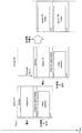
図1は、本実施形態に係るシステム1000の構成の一例を示す説明図である。システム1000としては、例えば、スマートフォンなどの通信装置や、ドローン(遠隔操作による動作、または、自律的な動作が可能な機器)、自動車などの移動体などが挙げられる。なお、システム1000の適用例は、上記に示す例に限られない。システム1000の他の適用例については、後述する。
(Configuration of system according to the present embodiment)
FIG. 1 is an explanatory diagram showing an example of the configuration of a
システム1000は、例えば、プロセッサ100(本実施形態に係る処理装置)と、画像を出力する機能を有する複数のセンサ200A、200B、…(本実施形態に係る画像センサ)と、メモリ300と、表示デバイス400とを有する。以下では、複数のセンサ200A、200B、…を総称して、または、複数のセンサ200A、200B、…のうちの1つのセンサを代表的に示して、「センサ200」と示す場合がある。
The
なお、図1では、2以上のセンサ200を有するシステム1000を示しているが、本実施形態に係るシステムが有するセンサ200の数は、図1に示す例に限られない。例えば、本実施形態に係るシステムは、2つのセンサ200、3つのセンサ200など、2以上の任意の数のセンサ200を有していてもよい。以下では、説明の便宜上、システム1000が有する複数のセンサ200のうちの2つのセンサ200から画像が出力される場合を主に例に挙げる。
Although FIG. 1 shows the
プロセッサ100と複数のセンサ200それぞれとは、1つのデータバスB1により電気的に接続される。データバスB1は、プロセッサ100とセンサ200それぞれとを接続する、一の信号の伝送路である。例えば、センサ200それぞれから出力される画像を示すデータ(以下、「画像データ」と示す場合がある。)が、センサ200からプロセッサ100へとデータバスB1を介して伝送される。
The
システム1000においてデータバスB1により伝送される信号は、例えば、CSI−2規格、PCI Expressなどの、データを時分割多重化して伝送することが可能な任意の規格によって、伝送される。以下では、データバスB1により伝送される信号が、CSI−2規格に従って伝送される例を示す。
The signal transmitted by the data bus B1 in the
また、プロセッサ100と複数のセンサ200それぞれとは、データバスB1とは異なる制御バスB2により電気的に接続される。制御バスB2は、プロセッサ100とセンサ200それぞれとを接続する、他の信号の伝送路である。例えば、プロセッサ100から出力される制御情報(後述する)が、プロセッサ100からセンサ200へと制御バスB2を介して伝送される。以下では、データバスB1と同様に、制御バスB2により伝送される信号が、CSI−2規格に従って伝送される例を示す。なお、図1では、プロセッサ100と複数のセンサ200それぞれとが、1つの制御バスB2により接続される例を示しているが、本実施形態に係るシステムは、センサ200ごとに制御バスが設けられる構成をとることも可能である。また、プロセッサ100と複数のセンサ200それぞれとは、制御バスB2を介して制御情報(後述する)を送受信する構成に限られず、例えば、後述する制御情報の送受信を行うことが可能な任意の通信方式の無線通信によって制御情報(後述する)を送受信する構成であってもよい。
Further, the
[1]システム1000における画像の伝送の概要
システム1000の構成について説明する前に、システム1000における画像の伝送の概要を説明する。
[1] Outline of Image Transmission in
システム1000のように、画像を出力する機能を有する複数のセンサがデータバスに接続されている場合には、データバス上で伝送されるデータの衝突を回避するために、画像を時分割多重化して伝送させることが、考えられる。
When a plurality of sensors having an image output function are connected to the data bus, as in the
図2は、複数のセンサが接続されているデータバスにおいて、画像を時分割多重化して伝送させる場合の一例を示す説明図である。図2は、撮像デバイスをそれぞれ有する2つのセンサ(図2に示すセンサ#1およびセンサ#2)が、撮像直後に画像をデータバスに出力する場合における、時分割多重化による伝送の一例を示している。
FIG. 2 is an explanatory diagram showing an example of a case where an image is time-division multiplexed and transmitted in a data bus to which a plurality of sensors are connected. FIG. 2 shows an example of transmission by time division multiplexing when two sensors (
図2に示すように、センサそれぞれが撮像直後に画像をデータバスに出力する場合には、時分割多重化による伝送を実現するために2つのセンサの露光タイミングを遅延させる必要がある。 As shown in FIG. 2, when each of the sensors outputs an image to the data bus immediately after capturing, it is necessary to delay the exposure timing of the two sensors in order to realize the transmission by time division multiplexing.
よって、図2に示す例では、センサ間で撮像のタイミングが合わないので、2つのセンサにおいて撮像された画像は、同一の時点に撮像された画像(または、同一の時点に撮像されたとみなせる画像)とはならない。 Therefore, in the example shown in FIG. 2, since the timings of image capturing do not match between the sensors, the images captured by the two sensors are images captured at the same time point (or images that can be considered to be imaged at the same time point). ) Is not possible.
そこで、システム1000では、所定の期間内において複数のセンサそれぞれに撮像を行わせ、複数のセンサから画像が出力されるタイミングをセンサ間でずらすことによって、時分割多重化による伝送を実現する。システム1000において、複数のセンサそれぞれにおける撮像の制御と、複数のセンサそれぞれにおける画像の出力タイミングの制御とは、例えばプロセッサ100により行われる。
Therefore, the
ここで、本実施形態に係る所定の期間内としては、例えば、1フレーム期間内や、画像の数ラインのずれに相当する期間内、同時などが挙げられる。なお、本実施形態に係る所定の期間内は、上記に示す例に限られない。本実施形態に係る所定の期間内は、例えば、システム1000の設計者や利用者などが、複数のセンサが同時に撮像したとみなせるとして設定した、任意の期間内であってもよい。
Here, as the predetermined period according to the present embodiment, for example, one frame period, a period corresponding to a shift of several lines of an image, simultaneous, and the like can be mentioned. Note that the predetermined period according to the present embodiment is not limited to the above example. The predetermined period according to the present embodiment may be, for example, an arbitrary period set by the designer or user of the
複数のセンサによる所定の期間内での撮像は、例えば、制御バスB2を介してプロセッサ100が送信する、撮像の制御のための制御情報に基づき制御される。
Imaging by a plurality of sensors within a predetermined period is controlled based on control information for controlling imaging, which is transmitted by the
撮像の制御のための制御情報としては、例えば、撮像命令(処理命令の一例)を含むデータが挙げられる。 The control information for controlling imaging includes, for example, data including an imaging command (an example of a processing command).
また、撮像の制御のための制御情報には、複数のセンサを同期して動作させるための同期信号が含まれていてもよい。同期信号を含む制御情報により、センサにおける撮像が制御される場合、“複数のセンサそれぞれにおいて所定の期間内に撮像された画像は、複数の画像センサが同期して撮像を行った画像である”といえる。なお、後述するように、システム1000において同期信号は、システム1000を構成する複数のセンサ200のうちの、マスタとして機能するセンサ200により送信されてもよい。
Further, the control information for controlling imaging may include a synchronization signal for operating a plurality of sensors in synchronization. When the image pickup by the sensor is controlled by the control information including the synchronization signal, “the image taken by each of the plurality of sensors within a predetermined period is an image taken by a plurality of image sensors in synchronization” Can be said. Note that, as will be described later, in the
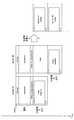
図3は、本実施形態に係るシステム1000における画像の伝送の概要を説明するための説明図である。図3は、撮像デバイスをそれぞれ有する2つのセンサ(図3に示すセンサ#1およびセンサ#2)が、同期信号Vsyncの受信に基づき同期して撮像を行う例を示している。
FIG. 3 is an explanatory diagram for explaining an outline of image transmission in the
ここで、システム1000において、同期信号Vsyncは、例えば制御バスB2を介してプロセッサ100から送信される。同期信号Vsyncが制御バスB2を介してプロセッサ100から送信されることによって、システム1000では、複数のセンサ200を同期して動作させることが実現される。つまり、システム1000では、制御バスB2を介したプロセッサ100による制御によって、例えば複数のセンサ200における撮像と画像の出力とを同期させることができる。
Here, in the
なお、システム1000において複数のセンサ200を同期して動作させる方法は、上記“プロセッサ100がシステム1000を構成する全センサ200に対して同期信号Vsyncを送信する方法”に限られない。
The method for operating the plurality of
例えば、システム1000では、プロセッサ100が制御バスB2を介してセンサ200それぞれの動作開始させた後に、複数のセンサ200のうちのある1つのセンサ200がマスタとして機能することによって、複数のセンサ200が同期して動作してもよい。具体的には、システム1000では、マスタとして機能するセンサ200が、同期信号Vsyncを他のセンサ200(スレーブとして機能するセンサ200)に対して送信する。そして、システム1000では、上記他のセンサ200がマスタとして機能するセンサ200から送信された同期信号Vsyncを受信することによって、複数のセンサ200を同期して動作させることが実現される。ここで、センサ200間における同期信号Vsyncの送受信は、例えばセンサ200間を接続する1ビットの専用線などを介して行われる。
For example, in the
図3に示すように、2つのセンサは、同期信号Vsyncに基づき同期して撮像を行う。そして、2つのセンサそれぞれは、撮像された画像を示すデータがデータバスB1上で衝突しないように、相異なるタイミングで出力される。例えば図3に示す例では、センサ#1は、撮像直後に画像をデータバスに出力し、センサ#2は、撮像後、図3において“Wait”と示されている遅延量分遅延させて画像をデータバスに出力している。
As shown in FIG. 3, the two sensors perform imaging in synchronization with each other based on the synchronization signal Vsync. Then, the two sensors are output at different timings so that the data indicating the captured image does not collide on the data bus B1. For example, in the example shown in FIG. 3, the
よって、図3に示す例では、センサ間で撮像のタイミングが揃った画像(所定の期間内に撮像された画像)を、データバスB1上で時分割多重化して伝送させることができる。 Therefore, in the example shown in FIG. 3, it is possible to time-division-multiplex and transmit an image (images captured within a predetermined period) whose imaging timings are uniform between the sensors on the data bus B1.
以下、図1に示すシステム1000の構成について説明しつつ、図3に示すような伝送を実現するための本実施形態に係る制御に係る処理を、説明する。
Hereinafter, while describing the configuration of the
[2]プロセッサ100(本実施形態に係る処理装置)
プロセッサ100は、MPU(Micro Processing Unit)などの演算回路で構成される、1または2以上のプロセッサや、各種処理回路などで構成される。また、プロセッサ100は、例えば、データバスB1を接続することが可能な端子や、制御バスB2を接続することが可能な端子などの外部バスを接続することが可能な端子を有し、データバスB1などの外部バスに接続可能である。プロセッサ100は、バッテリなどのシステム1000を構成する内部電源(図示せず)から供給される電力、または、システム1000の外部電源から供給される電力によって、駆動する。
[2] Processor 100 (processing device according to the present embodiment)
The
プロセッサ100は、本実施形態に係る処理装置の一例である。本実施形態に係る処理装置は、後述する処理部における処理(本実施形態に係る制御方法に係る処理)を行うことが可能な、任意の回路、任意のデバイスに適用することが可能である。
The
プロセッサ100は、“データバスB1に接続される複数のセンサ200それぞれにおいて所定の期間内に撮像された画像の出力制御(本実施形態に係る制御方法に係る制御)”を行う。
The
画像の出力制御は、例えば、プロセッサ100が備える処理部102において行われる。プロセッサ100では、画像の出力制御を行う特定のプロセッサ(または特定の処理回路)、または、複数のプロセッサ(または複数の処理回路)が、処理部102の役目を果たす。
The output control of the image is performed in the
なお、処理部102は、プロセッサ100における機能を便宜上切り分けたものである。よって、プロセッサ100では、例えば、本実施形態に係る画像の出力制御が、複数の機能ブロックによって行われてもよい。以下では、本実施形態に係る画像の出力制御が、処理部102において行われる場合を例に挙げる。
The
[1−1]本実施形態に係る画像の出力制御の一例
処理部102は、センサ200それぞれに対して制御情報を送信することによって、画像の出力制御を行う。
[1-1] Example of Image Output Control According to the Present Embodiment The
本実施形態に係る制御情報には、例えば、センサ200を示す識別情報と、制御のための情報と、処理命令とが含まれる。本実施形態に係る識別情報としては、例えば、センサ200に設定されているIDなどの、センサ200を特定することが可能な任意のデータが挙げられる。また、本実施形態に係る制御のための情報の具体例については、後述する。
The control information according to the present embodiment includes, for example, identification information indicating the
制御情報は、上述したように、例えば制御バスB2を介して送信される。 The control information is transmitted, for example, via the control bus B2 as described above.
また、処理部102により送信された制御情報は、例えば、センサ200それぞれが備えるレジスタ(記録媒体の一例)に記録される。そして、後述するように、センサ200は、レジスタに記憶されている制御情報に基づく出力タイミングで、所定の期間内に撮像された画像を出力する。
The control information transmitted by the
処理部102は、画像の出力制御として、例えば下記の(1)に示す第1の例に係る制御〜下記の(3)に示す第3の例に係る制御のいずれかの制御を行う。なお、本実施形態に係る画像の出力制御により実現される、システム1000における画像の出力例については、後述する。
As the image output control, the
(1)画像の出力制御の第1の例:遅延の制御
処理部102は、センサ200が画像を出力する際の遅延を制御する。
(1) First Example of Image Output Control: Delay Control The
処理部102は、例えば、画像を出力する際の遅延量を示すデータ(第1出力情報。制御のための情報の一例)を含む制御情報を、センサ200に対して送信することによって、センサ200における画像を出力する際の遅延を制御する。画像を出力する際の遅延量を示すデータ(以下、「遅延量を示すデータ」と示す場合がある。)としては、例えば、遅延時間を示すデータなどの数値などで遅延量を直接的に示すデータや、遅延量に対応付けられているIDなどの、遅延量を間接的に示すデータなどが、挙げられる。
The
(2)画像の出力制御の第2の例:送信間隔の制御
処理部102は、センサ200が画像を出力する際のパケットの出力間隔を制御する。画像を出力する際のパケットとしては、例えば、画像におけるライン単位のデータが、挙げられる。
(2) Second Example of Image Output Control: Control of Transmission Interval The
処理部102は、例えば、画像を出力する際のパケットの出力間隔(データピッチ)を示すデータ(第2出力情報。制御のための情報の一例)を含む制御情報を、センサ200に対して送信することによって、センサ200における画像を出力する際のパケットの出力間隔を制御する。画像を出力する際のパケットの出力間隔を示すデータ(以下、「パケットの出力間隔を示すデータ」と示す場合がある。)としては、例えば、時間間隔を示すデータなどの数値などで出力間隔を直接的に示すデータや、出力間隔に対応付けられているIDなどの、出力間隔を間接的に示すデータなどが、挙げられる。
The
(3)画像の出力制御の第3の例
処理部102は、上記(1)に示す第1の例に係る制御と上記(2)に示す第2の例に係る制御との双方の制御を、行ってもよい。
(3) Third Example of Image Output Control The
処理部102は、画像の出力制御として、例えば上記(1)に示す第1の例に係る制御〜上記(3)に示す第3の例に係る制御を行う。
As the image output control, the
プロセッサ100は、例えば処理部102を備えることによって、上述したような画像の出力制御に係る処理(本実施形態に係る制御方法に係る処理)を行う。
The
ここで、プロセッサ100において上記(1)に示す第1の例に係る制御〜上記(3)に示す第3の例に係る制御が行われることによって、センサ200それぞれでは、画像を出力する際の遅延と、画像を出力する際のパケットの出力間隔との一方または双方が、レジスタなどに記憶される制御情報に基づき制御される。
Here, the control of the first example shown in (1) above to the control of the third example shown in (3) above is performed in the
よって、プロセッサ100は、画像の出力制御に係る処理を行うことによって、センサ200(画像センサ)それぞれにおける画像の出力タイミングを、変えることができる。換言すると、システム1000では、センサ200それぞれにおける画像の出力タイミングは、プロセッサ100において画像の出力制御が行われることによって変わりうる。
Therefore, the
なお、プロセッサ100において行われる処理は、上述したような画像の出力制御に係る処理に限られない。
Note that the processing performed by the
例えば、プロセッサ100は、センサ200それぞれに対して制御情報を送信することによって、出力される画像の制御を行うことが、可能である。出力される画像の制御は、例えば処理部102により行われる。
For example, the
本実施形態に係出力される画像の制御としては、例えば、センサ200それぞれから出力される画像サイズの制御と、複数のセンサ200それぞれから出力される画像のフレームレートの制御との一方または双方が、挙げられる。
As the control of the image output according to the present embodiment, for example, one or both of the control of the image size output from each of the
プロセッサ100は、例えば、画像サイズを示すデータと、フレームレートを示すデータとの一方または双方(制御のための情報の一例)を含む制御情報を、センサ200に対して送信することによって、センサ200から出力される画像を制御する。
The
また、プロセッサ100は、例えば、メモリ300などの記録媒体へのデータバスB1を介して受信された画像データの記録制御に係る処理、表示デバイス400の表示画面への画像の表示制御に係る処理、任意のアプリケーションソフトウェアを実行する処理など、様々な処理を行うことが可能である。記録制御に係る処理としては、例えば“記録命令を含む制御データと記録媒体に記録させるデータとを、メモリ300などの記録媒体に伝達する処理”が、挙げられる。また、表示制御に係る処理としては、例えば“表示命令を含む制御データと表示画面に表示させるデータとを、表示デバイス400などの表示デバイスに伝達する処理”が、挙げられる。
Further, the
[3]センサ200(本実施形態に係る画像センサ)
センサ200は、画像センサである。本実施形態に係る画像センサは、例えば、デジタルスチルカメラやデジタルビデオカメラ、ステレオカメラなどの撮像デバイスや、赤外線センサ、距離画像センサなどの、撮像機能を有する任意のセンサデバイスを含み、撮像により生成された画像を出力する機能を有する。ここで、センサ200において生成される画像は、センサ200におけるセンシング結果を示すデータに該当する。
[3] Sensor 200 (image sensor according to the present embodiment)
The
センサ200は、例えば図1に示すように、他のセンサ200が接続されるデータバスB1に接続される。
The
上述したように、センサ200における撮像は、例えば、制御バスB2を介して受信される制御情報に基づいて行われ、プロセッサ100により制御される。例えばセンサ200における撮像がプロセッサ100により制御されることによって、センサ200における撮像とシステム1000を構成する他のセンサ200における撮像とは、所定の期間内に行われる。
As described above, the image pickup by the
また、センサ200は、制御情報に基づく出力タイミングで画像を出力する。ここで、センサ200における撮像と他のセンサ200における撮像とは、所定の期間内に行われるので、センサ200が制御情報に基づき出力する画像は、所定の期間内に撮像された画像であるといえる。上述したように、制御情報はプロセッサ100から送信され、センサ200は、例えば制御バスB2を介して制御情報を受信する。
Further, the
図4は、本実施形態に係るシステム1000を構成するセンサ200の構成の一例を示す説明図である。センサ200は、例えば、プロセッサ250と、ROM252と、レジスタ254と、センサデバイス256と、通信デバイス258とを有する。また、センサ200における各構成要素は、例えば内部バス260で接続される。また、センサ200は、例えば、データバスB1を接続することが可能な端子や、制御バスB2を接続することが可能な端子などの外部バスを接続することが可能な端子を有し、データバスB1などの外部バスに接続可能である。センサ200は、バッテリなどのシステム1000を構成する内部電源(図示せず)から供給される電力、または、システム1000の外部電源から供給される電力によって、駆動する。
FIG. 4 is an explanatory diagram showing an example of the configuration of the
なお、センサ200の構成は、図4に示す例に限られない。例えば、センサ200は、出力する画像を一時的に保持するための記録媒体を、さらに備えていてもよい。画像を一時的に保持するための記録媒体としては、例えば、RAM(Random Access Memory)などの揮発性メモリや、フラッシュメモリなどの不揮発性メモリなどが挙げられる。
The configuration of the
ここで、後述するセンサデバイス256として機能する撮像デバイスが、グローバルシャッター方式に対応する撮像デバイスである場合には、当該撮像デバイスを構成する、信号電荷を保持するための保持容量を利用して、画像を一時的に保持することが可能である。
Here, when the image pickup device functioning as a
よって、センサ200が、グローバルシャッター方式に対応する撮像デバイスをセンサデバイス256として備える場合には、センサ200は、上記画像を一時的に保持するための記録媒体を、別途備える必要はない。上記画像を一時的に保持するための記録媒体を別途備える必要がない場合には、センサ200の小型化やコストの低減などを図ることができる。
Therefore, when the
プロセッサ250は、センサ200全体を制御する役目を果たす。プロセッサ250による制御としては、例えば、レジスタ254への受信された制御情報の記録の制御、センサデバイス256の動作の制御、通信デバイス258の通信の制御などが挙げられる。
The
受信された制御情報の記録の制御に係る処理としては、例えば、“受信された制御情報に含まれる識別情報と、ROM252に記憶されている識別情報270とを比較し、比較結果に基づいて、受信された制御情報を選択的にレジスタ254に記録する処理”が、挙げられる。プロセッサ250は、例えば、受信された制御情報に含まれる識別情報と、ROM252に記憶されている識別情報270とが一致する場合に、受信された制御情報を選択的にレジスタ254に記録する。
As a process relating to control of recording of the received control information, for example, “the identification information included in the received control information and the
センサデバイス256の動作の制御に係る処理としては、例えば“撮像命令を含む制御情報が受信された場合に、センサデバイス256を動作させる命令を含む制御信号を、センサデバイス256に伝達する処理”が、挙げられる。
As a process related to the control of the operation of the
通信デバイス258の通信の制御に係る処理としては、例えば、“送信命令と送信するデータとを含む制御信号を、通信デバイス258に伝達する処理”が挙げられる。
Examples of the process related to control of communication of the
ROM252は、センサ200が備える一の記録媒体である。ROM252には、例えば、識別情報が記憶される。
The
レジスタ254は、センサ200が備える他の記録媒体である。レジスタ254には、例えば、制御バスB2を介して受信された制御情報が、記憶される。なお、図4では、制御情報がレジスタ254に記憶される例を示しているが、制御情報は、フラッシュメモリなどの不揮発性メモリや、ハードディスクなどの磁気記録媒体などの、他の記録媒体に記憶されてもよい。
The
センサデバイス256は、画像を生成するデバイスである。センサデバイス256としては、例えば、デジタルスチルカメラやデジタルビデオカメラなどの撮像デバイスや、赤外線センサ、距離画像センサなどの、撮像により画像を生成する機能を有する任意のセンサデバイスが、挙げられる。
The
センサデバイス256について一例を挙げて具体的に説明すると、センサデバイス256として機能する撮像デバイスは、例えば、光学系のレンズ(図示せず)と、撮像素子(図示せず)と、撮像素子(図示せず)に対応する画素アレイ(図示せず)と、ドライバ(図示せず)とを有する。
The
本実施形態に係る撮像素子(図示せず)としては、例えば、CMOS(Complementary Metal Oxide Semiconductor)や、CCD(Charge Coupled Device)が挙げられる。また、本実施形態に係る撮像素子(図示せず)は、CMOSにCCDなどの他の構成要素が積層されて構成される、スタック型の撮像素子であってもよい。つまり、撮像デバイスをセンサデバイス256として備えるセンサ200は、グローバルシャッター方式、または、ローリングシャッター方式によって撮像を行うことが可能である。
Examples of the image sensor (not shown) according to the present embodiment include CMOS (Complementary Metal Oxide Semiconductor) and CCD (Charge Coupled Device). Further, the image pickup device (not shown) according to the present embodiment may be a stack type image pickup device configured by stacking other constituent elements such as CCD on a CMOS. That is, the
画素アレイ(図示せず)は、複数の画素回路が行列状に配置される構成を有する。画素回路それぞれは、信号線を介してドライバ(図示せず)と電気的に接続される。画素回路は、例えば、フォトダイオードなどの受光素子やトランジスタ、容量素子などで構成される。画素回路では、ドライバ(図示せず)から信号線を介して伝達される制御信号によって、入射される光に応じた信号電荷の蓄電や、画素回路の初期化などが行われる。 The pixel array (not shown) has a configuration in which a plurality of pixel circuits are arranged in a matrix. Each pixel circuit is electrically connected to a driver (not shown) via a signal line. The pixel circuit is composed of, for example, a light receiving element such as a photodiode, a transistor, a capacitor, and the like. In the pixel circuit, a control signal transmitted from a driver (not shown) via a signal line stores a signal charge according to incident light and initializes the pixel circuit.
画素回路を構成する上記トランジスタとしては、例えば、バイポーラトランジスタや、TFT(Thin Film Transistor)やMOSFET(Metal-Oxide-Semiconductor Field Effect Transistor)などのFET(Field-Effect Transistor)などが、挙げられる。また、画素回路を構成する上記容量素子としては、例えばキャパシタが挙げられる。なお、画素回路を構成する上記容量素子には、配線などの寄生容量が含まれていてもよい。 Examples of the transistor forming the pixel circuit include a bipolar transistor and an FET (Field-Effect Transistor) such as a TFT (Thin Film Transistor) and a MOSFET (Metal-Oxide-Semiconductor Field Effect Transistor). Further, as the above-mentioned capacitive element forming the pixel circuit, for example, a capacitor can be cited. Note that the above-described capacitor element included in the pixel circuit may include a parasitic capacitance such as a wiring.
ドライバ(図示せず)は、画素回路に対して制御信号を伝達することによって、画素回路を駆動させる。 The driver (not shown) drives the pixel circuit by transmitting a control signal to the pixel circuit.
センサデバイス256として機能する撮像デバイスは、例えば上記に示すような構成を有する。なお、撮像デバイスの構成が、上記に示す例に限られないことは、言うまでもない。
The imaging device that functions as the
通信デバイス258は、例えば、データバスB1、制御バスB2などの接続されている外部バスを介して、外部デバイスと通信を行うためのデバイスである。通信デバイス258としては、例えば、CSI−2規格、PCI Expressなどの、データを時分割多重化して伝送することが可能な任意の規格に対応する通信を行うことが可能なデバイスが、挙げられる。
The
センサ200は、例えば図4に示す構成を有することによって、制御情報に基づく出力タイミングで画像を出力する。なお、センサ200の構成が、図4に示す例に限られないことは、言うまでもない。
The
センサ200における制御情報に基づく画像の出力に係る処理について、より具体的に説明する。センサ200は、制御情報に基づく画像の出力に係る処理として、例えば下記の(I)に示す第1の例に係る出力処理と下記の(II)に示す第2の例に係る出力処理のうちの一方または双方を行う。センサ200において、下記に示す制御情報に基づく画像の出力に係る処理は、例えば、センサ200を構成するプロセッサ250がレジスタ254に記憶されている制御情報272を参照することによって、行われる。
The process relating to the output of the image based on the control information in the
(I)第1の例に係る出力処理:制御情報に、画像を出力する際の遅延量を示すデータ(第1出力情報)が含まれる場合
制御情報に、遅延量を示すデータが含まれる場合、センサ200は、遅延量を示すデータが示す遅延量分遅延させて画像を出力する。
(I) Output process according to the first example: When the control information includes data indicating the delay amount when outputting an image (first output information) When the control information includes data indicating the delay amount The
センサ200では、例えば、上述した“画像を一時的に保持するための記録媒体”、または、上述した“センサデバイス256として機能するグローバルシャッター方式に対応する撮像デバイスを構成する保持容量”に、画像が保持されることによって、画像の出力の遅延が実現される。
In the
例えば、遅延量を示すデータが、遅延量を直接的に示すデータである場合、センサ200は、所定の時点から、遅延量を示すデータが示す遅延量に応じた時間が経過したときに、画像を出力する。
For example, when the data indicating the delay amount is the data indicating the delay amount directly, the
所定の時点としては、例えば、撮像命令や同期信号が受信された時点や、撮像における露光が終了した時点などが、挙げられる。所定の時点を示すデータは、例えば、ROM252などに予め記憶されていてもよいし、制御情報に含まれていてもよい。
Examples of the predetermined time point include a time point when an image pickup command and a synchronization signal are received, a time point when the exposure in the image pickup is finished, and the like. The data indicating the predetermined time point may be stored in advance in the
また、例えば、遅延量を示すデータが、遅延量を間接的に示すデータである場合、センサ200は、遅延量を示すデータに基づき遅延量を特定する。例えば、遅延量を間接的に示すデータが、遅延量に対応付けられているIDを示す場合、センサ200は、ROM252などの記録媒体に記憶されている、IDと遅延量とが対応付けられているテーブル(またはデータベース)を参照することによって、遅延量を特定する。そして、センサ200は、所定の時点から、特定された遅延量に応じた時間が経過したときに、画像を出力する。
Further, for example, when the data indicating the delay amount is the data indirectly indicating the delay amount, the
また、第1の例に係る出力処理のみが行われる場合、センサ200は、例えば、設定されている出力間隔に従って、画像のパケットを出力する。センサ200は、例えば、ROM252などの記録媒体に記憶されている出力間隔を示すデータを参照することによって、設定されている出力間隔を特定する。
Further, when only the output process according to the first example is performed, the
(II)第2の例に係る出力処理:制御情報に、画像を出力する際のパケットの出力間隔を示すデータ(第2出力情報)が含まれる場合
制御情報に、パケットの出力間隔を示すデータが含まれる場合、センサ200は、パケットの出力間隔を示すデータが示す出力間隔に従って、画像のパケットを出力する。
(II) Output process according to the second example: When the control information includes data (second output information) indicating the packet output interval when outputting an image The control information includes data indicating the packet output interval , Is included, the
例えば、パケットの出力間隔を示すデータが、出力間隔を直接的に示すデータである場合、センサ200は、一のパケットを出力した後、パケットの出力間隔を示すデータが示す出力間隔に応じた時間が経過したときに、次に出力するパケットを出力する。
For example, when the data indicating the packet output interval is the data directly indicating the output interval, the
また、例えば、パケットの出力間隔を示すデータが、出力間隔を間接的に示すデータである場合、センサ200は、パケットの出力間隔を示すデータに基づき出力間隔を特定する。例えば、出力間隔を間接的に示すデータが、出力間隔に対応付けられているIDを示す場合、センサ200は、ROM252などの記録媒体に記憶されている、IDと出力間隔とが対応付けられているテーブル(またはデータベース)を参照することによって、出力間隔を特定する。そして、センサ200は、一のパケットを出力した後、特定された出力間隔に応じた時間が経過したときに、次に出力するパケットを出力する。
Further, for example, when the data indicating the packet output interval is data indirectly indicating the output interval, the
また、第2の例に係る出力処理のみが行われる場合、センサ200は、例えば、設定されている遅延量分遅延させて、画像を出力する。センサ200は、例えば、ROM252などの記録媒体に記憶されている遅延量を示すデータを参照することによって、設定されている遅延量を特定する。
Further, when only the output process according to the second example is performed, the
センサ200は、例えば上記(I)に示す第1の例に係る出力処理と上記(II)に示す第2の例に係る出力処理のうちの一方または双方を行う。よって、システム1000では、プロセッサ100によりセンサ200に設定された制御情報に基づく出力タイミングで、所定の期間内に撮像された画像がセンサ200から出力される。そして、システム1000では、センサ200それぞれからデータバスB1を介して出力される画像が、プロセッサ100により取得される。
The
なお、本実施形態に係るセンサ200における制御情報に基づく画像の出力に係る処理は、上記(I)に示す第1の例に係る出力処理と上記(II)に示す第2の例に係る出力処理とに限られない。
The process related to the output of the image based on the control information in the
例えば、制御情報に画像サイズを示すデータが含まれる場合、センサ200は、制御情報が示す画像サイズの画像を出力する。
For example, when the control information includes data indicating the image size, the
また、制御情報にフレームレートを示すデータが含まれる場合、センサ200は、制御情報が示すフレームレートで、画像を出力させる。
Further, when the control information includes data indicating the frame rate, the
また、制御情報に、画像サイズを示すデータとフレームレートを示すデータとが含まれる場合、センサ200は、制御情報が示すフレームレートで、制御情報が示す画像サイズの画像を出力させる。
Further, when the control information includes data indicating the image size and data indicating the frame rate, the
[4]メモリ300
メモリ300は、システム1000が有する記録媒体である。メモリ300としては、例えば、RAMなどの揮発性メモリや、フラッシュメモリなどの不揮発性メモリなどが挙げられる。
[4]
The
メモリ300には、例えばセンサ200それぞれから出力された画像が記憶される。メモリ300への画像の記録は、例えばプロセッサ100により制御される。
The images output from the
[5]表示デバイス400
表示デバイス400は、システム1000が有する表示デバイスである。表示デバイス400としては、例えば、液晶ディスプレイ(Liquid Crystal Display)や有機ELディスプレイ(Organic Electro-Luminescence Display。または、OLEDディスプレイ(Organic Light Emitting Diode Display)ともよばれる。)などが挙げられる。
[5]
The
表示デバイス400の表示画面には、例えば、センサ200それぞれから出力された画像や、プロセッサ100において実行されるアプリケーションに係る画面、UI(User Interface)に係る画面など、様々な画像や画面が表示される。表示デバイス400の表示画面への画像などの表示は、例えばプロセッサ100により制御される。
On the display screen of the
[6]システム1000が奏する効果、およびシステム1000の変形例
システム1000は、例えば図1に示す構成を有する。
[6] Effects of
システム1000では、プロセッサ100と複数のセンサ200とが、データバスB1により接続される。また、システム1000において複数のセンサ200における画像の出力は、プロセッサ100により画像の出力制御が行われることによって、制御される。よって、システム1000では、データバスB1に接続された複数のセンサ200が独立に出力する、所定の期間内に撮像された画像が、データバスB1上で時分割多重化して伝送される。そして、プロセッサ100は、複数のセンサ200が独立に出力する画像を、データバスB1を介して受信することができる。
In the
したがって、プロセッサ100(本実施形態に係る処理装置)と複数のセンサ200(本実施形態に係る画像センサ)とがデータバスB1で接続される場合に、複数のセンサ200それぞれにおいて所定の期間内に撮像された画像を、データバスB1により伝送することができる。
Therefore, when the processor 100 (the processing device according to the present embodiment) and the plurality of sensors 200 (the image sensor according to the present embodiment) are connected by the data bus B1, each of the plurality of
また、システム1000により、例えば“撮像のタイミングが同期されている複数のセンサ200(所定の期間内に撮像が行われる複数のセンサ200の一例)がそれぞれ独立に出力する画像を、同一のデータバスB1上で時分割多重化する機構”が、実現される。
In addition, by the
また、システム1000では、プロセッサ100と複数のセンサ200とが、データバスB1により接続されるので、CSI−2規格のような既存の規格を単に利用する場合よりも、プロセッサ100に接続されるデータバスの数を減らすことができる。
Further, in the
また、システム1000では、プロセッサ100に接続されるデータバスの数を減らすことができることによって、下記のような効果が奏される。
・プロセッサ100と複数のセンサ200とを接続する配線領域をより小さくすることができる
・例えばデータバスを接続するための端子数が減ることなどにより、プロセッサ100のハードウェア構成をより簡略化することができる。
Further, in the
-The wiring area connecting the
なお、本実施形態に係るシステムの構成は、図1に示す例に限られない。 The configuration of the system according to this embodiment is not limited to the example shown in FIG.
例えば、システムの外部の記録媒体に複数のセンサ200から出力される画像が記憶される場合、または、複数のセンサ200から出力される画像がプロセッサ100が備えるメモリに記憶される場合には、本実施形態に係るシステムは、図1に示すメモリ300を有していなくてもよい。
For example, when images output from the plurality of
また、本実施形態に係るシステムは、図1に示す表示デバイス400を有さない構成をとることも可能である。
Further, the system according to the present embodiment can also be configured without the
また、本実施形態に係るシステムは、後述する本実施形態に係るシステムが適用される電子機器が有する機能に応じた、任意の構成を有していてもよい。 Further, the system according to the present embodiment may have any configuration according to the function of the electronic device to which the system according to the present embodiment described later is applied.
また、本実施形態に係るシステムは、プロセッサにM本(Mは、センサ200の数よりも小さい整数)のデータバスが接続される構成であってもよい。本実施形態に係るシステムが、プロセッサにM本(Mは、システムが有するセンサ200の数よりも小さい整数)のデータバスが接続される構成であっても、CSI−2規格のような既存の規格を単に利用する場合よりも、プロセッサに接続されるデータバスの数を減らすことができる。
The system according to the present embodiment may have a configuration in which M data buses (M is an integer smaller than the number of sensors 200) are connected to the processor. Even if the system according to the present embodiment has a configuration in which M data buses (M is an integer smaller than the number of
[7]本実施形態に係るシステムの適用例
以上、本実施形態として、システムを挙げて説明したが、本実施形態は、かかる形態に限られない。本実施形態は、例えば、スマートフォンなどの通信装置や、ドローン(遠隔操作による動作、または、自律的な動作が可能な機器)、自動車などの移動体、PC(Personal Computer)などのコンピュータ、タブレット型の装置、ゲーム機など、様々な電子機器に適用することができる。
[7] Application Example of System According to Present Embodiment As described above, the system has been described as the present embodiment, but the present embodiment is not limited to this mode. In the present embodiment, for example, a communication device such as a smartphone, a drone (device capable of remote operation or autonomous operation), a mobile body such as an automobile, a computer such as a PC (Personal Computer), and a tablet type. The present invention can be applied to various electronic devices such as a device, a game machine, and the like.
また、上記では、本実施形態に係るシステムを構成する処理装置として、プロセッサを例に挙げたが、本実施形態に係る処理装置は、上記に示す例に限られない。例えば、本実施形態に係る処理装置は、データバスに接続される複数の画像センサそれぞれから当該データバスを介して出力される画像の出力制御を行うことが可能な、任意の処理回路、または、任意のデバイスに適用することができる。 Further, in the above description, the processor is given as an example of the processing device that configures the system according to the present embodiment, but the processing device according to the present embodiment is not limited to the example described above. For example, the processing device according to the present embodiment is an arbitrary processing circuit capable of performing output control of an image output from each of a plurality of image sensors connected to a data bus via the data bus, or It can be applied to any device.
(本実施形態に係るシステムにおける画像の出力例)
次に、上述したシステム1000における画像の出力例を、説明する。以下では、データバスB1により伝送される信号が、CSI−2規格に従って伝送される例を示す。
(Example of image output in the system according to the present embodiment)
Next, an example of outputting an image in the
図5は、本実施形態に係るシステム1000を構成するセンサ200により撮像された画像データの一例を示している。
FIG. 5 shows an example of image data imaged by the
センサ200により撮像された画像データは、例えばN(Nは、1以上の整数)行のデータで構成され、1行ずつデータバスB1に出力される。
The image data captured by the
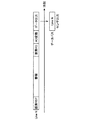
図6は、本実施形態に係るシステム1000を構成するデータバスB1上で伝送される画像データのパケット列の一例を示しており、CSI−2規格に従ったパケット列の一例を示している。図6に示す“FS”は、CSI−2規格におけるFS(Frame Start)パケットを示しており、図6に示す“FE”は、CSI−2規格におけるFE(Frame End)パケットを示している。また、図6に示す“PH”は、パケットヘッダを示しており、図6に示す“PF”は、パケットフッタを示している。
FIG. 6 shows an example of a packet sequence of image data transmitted on the data bus B1 that constitutes the
CSI−2規格では、画像データの先頭にFSパケットP1が発行された後、画像データパケットP2がNパケット発行され、最後にFEパケットP3が発行される。一の画像データパケットP1と他の画像データパケットP1の間隔はラインブランキングBL1とよばれ、FEパケットP3と次のFSパケットP1の間隔はフレームブランキングBL2とよばれる。 According to the CSI-2 standard, an FS packet P1 is issued at the beginning of image data, N packets of image data packets P2 are issued, and an FE packet P3 is finally issued. The interval between one image data packet P1 and another image data packet P1 is called line blanking BL1, and the interval between the FE packet P3 and the next FS packet P1 is called frame blanking BL2.
図7は、本実施形態に係るシステム1000を構成するメモリ300上に確保されたフレームバッファの一例を示している。
FIG. 7 shows an example of a frame buffer secured on the
図6に示すパケット列を受信したプロセッサ100は、受信した画像データを、図7に示すようにメモリ300のフレームバッファに記録させる。
The
センサ200において撮像された画像がCSI−2規格に従って伝送される場合、システム1000では、図6に示すような画像データのパケット列がデータバスB1上で伝送され、プロセッサ100により受信された画像データは、図7に示すようにフレームバッファに記憶される。
When the image captured by the
次に、センサ200が、センサデバイス256として撮像デバイスを備える場合を例に挙げて、センサ200から出力される画像の出力タイミングの例を説明する。
Next, an example of the output timing of the image output from the
[I]対応するシャッター方式に応じた画像の出力例
プロセッサ100による出力制御により実現される、センサ200から出力される画像の出力タイミングの例を説明する前に、センサが備える撮像デバイスが対応するシャッター方式に応じた画像の出力例を説明する。
[I] Example of Output of Image According to Corresponding Shutter Method Before describing an example of output timing of an image output from the
(I−1)撮像デバイスが、ローリングシャッター方式に対応する場合
図8は、ローリングシャッター方式に対応する撮像デバイスを備えるセンサにおける動作の一例を示す説明図である。図8は、ローリングシャッター方式に対応する撮像デバイスを備えるセンサ(以下、「ローリングシャッター方式に対応するセンサ」と示す場合がある。)が、ある1つのNラインを撮像してNラインに対応する画像データを出力するまでの動作を示している。
(I-1) When the image pickup device corresponds to the rolling shutter system FIG. 8 is an explanatory diagram showing an example of the operation of the sensor including the image pickup device corresponding to the rolling shutter system. In FIG. 8, a sensor equipped with an imaging device compatible with the rolling shutter system (hereinafter sometimes referred to as “sensor compatible with the rolling shutter system”) images one N line and corresponds to the N line. The operation until the image data is output is shown.
図8に示す“画素RST”は、画素のリセットを示しており、図8に示す“画素RD”は、入射される光に応じて蓄積された電荷を読み出すことを示している。図8に示す“AD変換”は、アナログ−デジタル変換回路(図示せず)により、読み出された電荷に応じたアナログ信号をデジタル信号に変換することを示している。以下、他の図においても同様とする。 "Pixel RST" shown in FIG. 8 indicates pixel reset, and "Pixel RD" shown in FIG. 8 indicates that charges accumulated in response to incident light are read out. "AD conversion" shown in FIG. 8 indicates that an analog-digital conversion circuit (not shown) converts an analog signal corresponding to the read charges into a digital signal. Hereinafter, the same applies to other figures.
Nラインを撮像する場合、ローリングシャッター方式に対応するセンサでは、Nラインに対応する画素のリセット(図8に示す画素RST)が行われる。ここで、画素のリセットは、撮像デバイスのシャッターを開く動作に該当する。 When imaging the N line, the sensor corresponding to the rolling shutter system resets the pixel corresponding to the N line (pixel RST shown in FIG. 8). Here, resetting the pixel corresponds to the operation of opening the shutter of the image pickup device.
ローリングシャッター方式に対応するセンサでは、画素に入射される光に応じた信号電荷が蓄積され(図8に示す蓄積)、その後、蓄積された電荷が読み出される(図8に示す画素RD)。ここで、蓄積された電荷の読み出しは、撮像デバイスのシャッターを閉じる動作に該当する。 In the sensor corresponding to the rolling shutter system, signal charges corresponding to the light incident on the pixel are accumulated (accumulation shown in FIG. 8), and then the accumulated charges are read out (pixel RD shown in FIG. 8). Here, reading out the accumulated charges corresponds to the operation of closing the shutter of the imaging device.
ローリングシャッター方式に対応するセンサでは、読み出された電荷がアナログ−デジタル変換されることによって(図8に示すAD変換)Nラインに対応するデジタルデータが得られ、当該デジタルデータがデータバスに出力される(図8に示すデータ出力)。 In the sensor corresponding to the rolling shutter system, the read charges are analog-digital converted (AD conversion shown in FIG. 8) to obtain digital data corresponding to the N line, and the digital data is output to the data bus. (Data output shown in FIG. 8).
図9は、ローリングシャッター方式に対応する撮像デバイスを備えるセンサにおける動作の一例を示す説明図であり、図8に示すあるNラインにおける動作が、1ライン〜Nライン(図9において、Nは、4以上の整数)の複数ラインについて、連続して行われる例を示している。 FIG. 9 is an explanatory diagram showing an example of the operation of a sensor including an image pickup device compatible with the rolling shutter system, and the operation at a certain N line shown in FIG. 8 is 1 line to N line (N in FIG. This is an example in which a plurality of lines (an integer of 4 or more) are continuously performed.
ローリングシャッター方式に対応するセンサでは、図9に示すように、各ラインに対応するデジタルデータのデータバスへの出力が衝突しないようにラインごとにタイミングをずらして、画素リセット(図9に示す画素RST)〜データ出力(図9に示すデータ出力)という一連の動作が行われる。 In the sensor corresponding to the rolling shutter system, as shown in FIG. 9, pixel reset (pixels shown in FIG. 9 is performed by shifting the timing for each line so that the output of the digital data corresponding to each line does not collide. A series of operations from RST) to data output (data output shown in FIG. 9) is performed.
図10は、ローリングシャッター方式に対応する撮像デバイスをそれぞれ備える、2つのセンサにおける動作の一例を示す説明図である。図10は、データバス上で画像データが時分割多重化されるように、2つのローリングシャッター方式に対応するセンサ(センサ#1およびセンサ#2)それぞれにおいて図9に示す動作が行われる場合の一例を示している。
FIG. 10 is an explanatory diagram showing an example of the operation of two sensors, each equipped with an imaging device compatible with the rolling shutter method. FIG. 10 shows a case where the operation shown in FIG. 9 is performed in each of the sensors (
データバス上のデータの出力タイミングが、2つのローリングシャッター方式に対応するセンサで重ならないようにするためには、図2を参照して示したように2つのローリングシャッター方式に対応するセンサの撮像のタイミングをずらす必要がある。そのため、図10に示す例では、一のセンサが全てのラインに対応するデータをデータバスへ出力した後に、他のセンサにおける各ラインに対応するデータのデータバスへの出力が行われている。よって、図10に示す例では、2つのローリングシャッター方式に対応するセンサにおいて撮像された画像は、同一の時点に撮像された画像(または、同一の時点に撮像されたとみなせる画像)とはならない。 In order to prevent the output timing of the data on the data bus from overlapping with the sensors corresponding to the two rolling shutter systems, as shown with reference to FIG. 2, the image capturing of the sensors corresponding to the two rolling shutter systems is performed. It is necessary to shift the timing of. Therefore, in the example shown in FIG. 10, one sensor outputs the data corresponding to all the lines to the data bus, and then the data corresponding to each line of the other sensor is output to the data bus. Therefore, in the example illustrated in FIG. 10, the images captured by the sensors corresponding to the two rolling shutter systems are not images captured at the same time point (or images that can be considered to be imaged at the same time point).
(I−2)撮像デバイスが、グローバルシャッター方式に対応する場合
図11は、グローバルシャッター方式に対応する撮像デバイスを備えるセンサにおける動作の一例を示す説明図である。図11は、グローバルシャッター方式に対応する撮像デバイスを備えるセンサ(以下、「グローバルシャッター方式に対応するセンサ」と示す場合がある。)が、ある1つのNラインを撮像してNラインに対応する画像データを出力するまでの動作を示している。
(I-2) When the image pickup device corresponds to the global shutter system FIG. 11 is an explanatory diagram showing an example of the operation of the sensor including the image pickup device corresponding to the global shutter system. In FIG. 11, a sensor including an imaging device compatible with the global shutter system (hereinafter, sometimes referred to as “sensor compatible with the global shutter system”) images one N line and corresponds to the N line. The operation until the image data is output is shown.
Nラインを撮像する場合、グローバルシャッター方式に対応するセンサでは、Nラインに対応する画素のリセット(図11に示す画素RST)が行われる。 When capturing the N line, the sensor corresponding to the global shutter system resets the pixel corresponding to the N line (pixel RST shown in FIG. 11).
グローバルシャッター方式に対応するセンサでは、画素に入射される光に応じた信号電荷が蓄積され(図11に示す蓄積)、その後、蓄積された電荷が読み出される(図11に示す画素RD)。 In the sensor corresponding to the global shutter system, signal charges corresponding to the light incident on the pixel are accumulated (accumulation shown in FIG. 11), and then the accumulated charges are read out (pixel RD shown in FIG. 11).
グローバルシャッター方式に対応するセンサでは、ローリングシャッター方式に対応するセンサと異なり、読み出された電荷は、例えば画素に隣接する容量素子に転送され、当該容量素子で保持される(図11に示す容量保持)。以下では、上記画素に隣接する容量素子のような、読み出された電荷が保持される容量素子を、「保持容量」と示す。 In the sensor corresponding to the global shutter method, unlike the sensor corresponding to the rolling shutter method, the read charges are transferred to, for example, the capacitive element adjacent to the pixel and are held by the capacitive element (the capacitance shown in FIG. 11). Retention). Hereinafter, a capacitive element that holds the read charges, such as a capacitive element adjacent to the pixel, is referred to as a “retention capacitance”.
グローバルシャッター方式に対応するセンサでは、保持容量に保持されている電荷がアナログ−デジタル変換されることによって(図11に示すAD変換)Nラインに対応するデジタルデータが得られ、当該デジタルデータがデータバスに出力される(図11に示すデータ出力)。つまり、グローバルシャッター方式に対応するセンサでは、保持容量に電荷を保持することによって、アナログ−デジタル変換とデータバスへのデータの出力とを、遅らせることが可能である。 In the sensor corresponding to the global shutter system, the electric charge held in the holding capacitor is subjected to analog-digital conversion (AD conversion shown in FIG. 11) to obtain digital data corresponding to the N line, and the digital data corresponds to the data. It is output to the bus (data output shown in FIG. 11). That is, in the sensor corresponding to the global shutter system, the analog-digital conversion and the output of data to the data bus can be delayed by holding the charge in the holding capacitor.
図12は、グローバルシャッター方式に対応する撮像デバイスを備えるセンサにおける動作の一例を示す説明図であり、図12に示すあるNラインにおける動作が、1ライン〜Nライン(図12において、Nは、4以上の整数)の複数ラインについて、連続して行われる例を示している。 FIG. 12 is an explanatory diagram showing an example of the operation of a sensor including an image pickup device compatible with the global shutter system, and the operation of a certain N line shown in FIG. This is an example in which a plurality of lines (an integer of 4 or more) are continuously performed.
グローバルシャッター方式に対応するセンサでは、図12に示すように、画素リセット(図12に示す画素RST)を全てのラインで同時に開始することができる。また、グローバルシャッター方式に対応するセンサでは、例えば図12に示すように、信号電荷の蓄積(図12に示す蓄積)と蓄積された電荷の読み出し(図12に示す画素RD)とが、全てのラインで同時に行われる。なお、グローバルシャッター方式に対応するセンサでは、信号電荷の蓄積(図12に示す蓄積)と蓄積された電荷の読み出し(図12に示す画素RD)とを、ラインごとに変えることも可能である。 In the sensor corresponding to the global shutter system, as shown in FIG. 12, pixel reset (pixel RST shown in FIG. 12) can be simultaneously started in all lines. Further, in the sensor corresponding to the global shutter system, for example, as shown in FIG. 12, the accumulation of signal charges (accumulation shown in FIG. 12) and the readout of accumulated charges (pixel RD shown in FIG. 12) are all performed. At the same time on the line. In the sensor corresponding to the global shutter system, the accumulation of signal charges (accumulation shown in FIG. 12) and the readout of accumulated charges (pixel RD shown in FIG. 12) can be changed for each line.
グローバルシャッター方式に対応するセンサは、各ラインにおいて読み出された電荷を保持容量に転送して保持容量に保持させ(図12に示す容量保持)、保持容量に保持された電荷を1ラインずつ順次にアナログ−デジタル変換して、データバスへとデータを出力する(図12に示すAD変換およびデータ出力)。なお、図12では、ライン1(図12に示すLine1)については、便宜上、読み出された電荷を保持容量に転送して保持容量に保持させることを、省略している(なお、後述する図13、図14においても、図12と同様に省略する。)。
The sensor corresponding to the global shutter system transfers the charges read in each line to a holding capacitor and holds them in the holding capacitor (capacity holding shown in FIG. 12), and sequentially holds the charges held in the holding capacitor line by line. To analog-to-digital conversion and output the data to the data bus (AD conversion and data output shown in FIG. 12). Note that in FIG. 12, for the line 1 (
例えば図12に示すように、グローバルシャッター方式に対応するセンサは、各ラインにおいて読み出された電荷を保持容量に保持させることが可能であるので、各ラインに対応するデータをデータバスへと出力する出力タイミングを、データの衝突が回避されるようにずらすことができる。 For example, as shown in FIG. 12, since the sensor corresponding to the global shutter system can hold the charges read in each line in the holding capacitor, the data corresponding to each line is output to the data bus. It is possible to shift the output timing to be performed so as to avoid data collision.
[II]システム1000におけるセンサ200からの画像の出力例
次に、システム1000におけるセンサ200からの画像の出力例を説明する。
[II] Example of Output of Image from
以下では、システム1000を構成するセンサ200が備えるセンサデバイス256が、グローバルシャッター方式に対応するセンサであり、保持容量を利用して画像を一時的に保持する場合を、主に例に挙げる。上述したように、グローバルシャッター方式に対応するセンサを構成する保持容量を利用して画像を一時的に保持する場合には、センサ200は、RAMなどの画像を一時的に保持するための記録媒体を備えていなくてもよい。また、上述したように、センサ200は、RAMなどの画像を一時的に保持するための記録媒体を備えることによって、画像を一時的に保持することも可能である。
Hereinafter, a case where the
(II−1)第1の出力例
図13は、本実施形態に係るシステム1000におけるセンサ200からの画像の出力の第1の例を示す説明図である。図13は、グローバルシャッター方式に対応するセンサをセンサデバイス256としてそれぞれ備える、センサ200A、200Bにおける動作の一例を示している。センサ200Aとセンサ200Bとは、例えば制御バスB2を介して同期して動作する。
(II-1) First Output Example FIG. 13 is an explanatory diagram showing a first example of image output from the
センサ200A、200Bでは、例えば同期信号Vsyncの受信に基づき同期して画素のリセット(図13に示す画素RST)が行われ、その後、信号電荷の蓄積(図13に示す蓄積)と蓄積された電荷の読み出し(図13に示す画素RD)とが行われる。
In the
また、センサ200A、200Bそれぞれは、図12を参照して示したように、各ラインにおいて読み出された電荷を保持容量に転送して保持容量に保持させ(図13に示す容量保持)、保持容量に保持された電荷を1ラインずつ順次にアナログ−デジタル変換して、データバスB1へとデータを出力する(図13に示すAD変換およびデータ出力)。データバスB1へと出力される各ラインにそれぞれ対応するデータが、「画像のパケット」に該当する。
Further, as shown with reference to FIG. 12, each of the
ここで、上述したように、センサ200A、200Bそれぞれは、例えばレジスタ254に記憶されている制御情報に基づく出力タイミングで、画像を出力する。
Here, as described above, each of the
例えば、遅延量を示すデータが制御情報に含まれる場合、センサ200A、200Bそれぞれは、当該遅延量を示すデータに対応する遅延量分、出力が遅延するように、各ラインにおいて読み出された電荷を保持容量に保持させる。
For example, when the data indicating the delay amount is included in the control information, each of the
また、パケットの出力間隔を示すデータが制御情報に含まれる場合、センサ200A、200Bそれぞれは、当該出力間隔を示すデータが示す出力間隔に従って、各ラインに対応するデータをデータバスB1へ出力する。
When the data indicating the packet output interval is included in the control information, each of the
図13に示す例は、センサ200Bが備えるレジスタ254に記憶されている制御情報が示す遅延量が、センサ200Aが備えるレジスタ254に記憶されている制御情報が示す遅延量よりも大きい例を示している。より具体的には、図13に示す例は、センサ200Aが全てのラインに対応するデータをデータバスB1へ出力した後に、センサ200Bにおける各ラインに対応するデータの出力が行われるような制御情報が、センサ200A、200Bそれぞれのレジスタ254に記憶されている例を示している。
In the example shown in FIG. 13, the delay amount indicated by the control information stored in the
ここで、図13に示す例では、センサ200Aが各ラインに対応するデータ(画像のパケット)を出力する間隔と、センサ200Bが各ラインに対応するデータを出力する間隔とが、同一である例を示しているが、センサ200A、200Bそれぞれがデータを出力する間隔は、図13に示す例に限られない。例えば、センサ200A、200Bそれぞれが、制御情報が示す出力間隔に従って各ラインに対応するデータをデータバスB1へ出力することによって、センサ200Aにおけるデータの出力間隔とセンサ200Bにおけるデータの出力間隔とは、異なっていてもよい。
Here, in the example illustrated in FIG. 13, an example in which the interval at which the
センサ200A、200Bそれぞれが、制御情報に基づく出力タイミングで画像を出力することによって、例えば図13に示すように、センサ200A、200B間で撮像のタイミングが揃った画像(所定の期間内に撮像された画像)を、データバスB1上で時分割多重化して伝送させることができる。
Each of the
(II−2)第2の出力例
図14は、本実施形態に係るシステム1000におけるセンサ200からの画像の出力の第2の例を示す説明図である。図14は、グローバルシャッター方式に対応するセンサをセンサデバイス256としてそれぞれ備える、センサ200A、200Bにおける動作の他の例を示している。センサ200Aとセンサ200Bとは、例えば制御バスB2を介して同期して動作する。
(II-2) Second Output Example FIG. 14 is an explanatory diagram showing a second example of image output from the
図14に示すセンサ200A、200Bそれぞれにおける動作は、図13に示す第1の出力例におけるセンサ200A、200Bの動作と同一である。しかしながら、センサ200A、200Bそれぞれが参照する制御情報が図13に示す例と異なることによって、図14に示す第2の出力例と図13に示す第1の出力例とでは、画像データの出力順序が異なっている。
The operation of each of the
図14に示す例は、センサ200Bが備えるレジスタ254に記憶されている制御情報が示す遅延量が、センサ200Aが備えるレジスタ254に記憶されている制御情報が示す遅延量よりも大きい例を示している。より具体的には、図14に示す例は、センサ200Aにおける各ラインに対応するデータをデータバスB1へ出力と、センサ200Bにおける各ラインに対応するデータをデータバスB1へ出力とが、交互に行われるような制御情報が、センサ200A、200Bそれぞれのレジスタ254に記憶されている例を示している。
In the example shown in FIG. 14, the delay amount indicated by the control information stored in the
ここで、図14に示す例では、センサ200Aが各ラインに対応するデータ(画像のパケット)を出力する間隔と、センサ200Bが各ラインに対応するデータを出力する間隔とが、同一である例を示しているが、センサ200A、200Bそれぞれがデータを出力する間隔は、図14に示す例に限られない。例えば、センサ200A、200Bそれぞれが、制御情報が示す出力間隔に従って各ラインに対応するデータをデータバスB1へ出力することによって、センサ200Aにおけるデータの出力間隔とセンサ200Bにおけるデータの出力間隔とは、(データバスB1上でデータの衝突が発生しない範囲で)異なっていてもよい。
Here, in the example illustrated in FIG. 14, an example in which the interval at which the
センサ200A、200Bそれぞれが、制御情報に基づく出力タイミングで画像を出力することによって、例えば図14に示すように、センサ200A、200B間で撮像のタイミングが揃った画像(所定の期間内に撮像された画像)を、データバスB1上で時分割多重化して伝送させることができる。
Each of the
(II−3)他の出力例
本実施形態に係るシステム1000におけるセンサ200からの画像の出力例は、上記(II−1)に示す第1の出力例と上記(II−2)に示す第2の出力例とに限られない。
(II-3) Other Output Examples An output example of an image from the
例えば、図13に示す第1の出力例および図14に示す第2の出力例では、2つのセンサ200A、200Bにおける画像の出力を例に挙げた。しかしながら、システム1000を構成するセンサ200が3つ以上である場合においても、各センサ200が制御情報に基づく出力タイミングで画像を出力することによって、第1の出力例および第2の出力例と同様に、センサ200それぞれから出力される画像をデータバスB1上で時分割多重化して伝送させることができる。
For example, in the first output example shown in FIG. 13 and the second output example shown in FIG. 14, the output of images from the two
また、図13に示す第1の出力例および図14に示す第2の出力例では、“複数のセンサ200が、グローバルシャッター方式に対応するセンサをセンサデバイス256として備え、保持容量に電荷を保持することによって、データバスB1へのデータの出力タイミングが調整される例”を示した。しかしながら、システム1000では、例えば、センサ200が、RAMなどの画像を一時的に保持するための記録媒体を備え、各ラインに対応するアナログ−デジタル変換されたデータを当該記録媒体に保持するすることによって、センサ200それぞれがデータバスB1へとデータを出力する出力タイミングが、調整されてもよい。
In addition, in the first output example shown in FIG. 13 and the second output example shown in FIG. 14, “a plurality of
センサ200がRAMなどの記録媒体に各ラインに対応するデータを保持する構成であっても、各センサ200が制御情報に基づく出力タイミングで画像を出力することによって、第1の出力例および第2の出力例と同様に、センサ200それぞれから出力される画像をデータバスB1上で時分割多重化して伝送させることができる。また、センサ200がRAMなどの記録媒体に各ラインに対応するデータを保持する構成である場合、センサ200は、例えば、グローバルシャッター方式に対応するセンサや、上述したローリングシャッター方式に対応するセンサなどのグローバルシャッター方式に対応するセンサ以外のセンサデバイスを、センサデバイス256として備えることが可能である。
Even in the configuration in which the
[III]プロセッサ100における画像の出力制御に係る処理(本実施形態に係る制御方法に係る処理)の一例
次に、上述したシステム1000におけるセンサ200からの画像の出力例を実現させることが可能な、プロセッサ100における画像の出力制御に係る処理の一例を説明する。
[III] Example of Process Related to Image Output Control in Processor 100 (Process Related to Control Method According to Present Embodiment) Next, an example of image output from the
図15は、本実施形態に係るシステム1000を構成するプロセッサ100における画像の出力制御に係る処理(本実施形態に係る制御方法に係る処理)の一例を示す流れ図である。図15では、システム1000が、センサ200A、200Bという2つの画像センサを有している場合における、プロセッサ100における画像の出力制御に係る処理の一例を示している。
FIG. 15 is a flow chart showing an example of processing relating to image output control in the
プロセッサ100は、制御対象のセンサ200A、200Bそれぞれの電源をオン状態にし、リセット解除を行う(S100)。ステップS100の処理は、例えばセンサ200A、200Bを初期化する処理の一例に該当する。
The
プロセッサ100は、センサ200Aのレジスタ設定を行う(S102)。プロセッサ100は、制御バスB2を介して制御情報を送信することによって、センサ200Aのレジスタ設定を行う。
The
ここで、プロセッサ100は、例えば、センサ200Aが指定され、かつ、センサ200Aが備えるレジスタのアドレスが指定された制御情報を送信することによって、センサ200Aのレジスタ設定を行う。また、プロセッサ100は、例えば、制御対象の全てのセンサ200が指定され、かつ、センサ200が備えるレジスタのアドレスが指定された制御情報を送信することによって、センサ200Aのレジスタ設定を行うことも可能である。制御対象の全てのセンサ200が指定され、かつ、センサ200が備えるレジスタのアドレスが指定された制御情報が送信されることは、例えば、全てのセンサ200が備えるレジスタに同一のデータを同期して記録させる場合に有効である。
Here, for example, the
プロセッサ100は、センサ200Bのレジスタ設定を行う(S104)。プロセッサ100は、ステップS102と同様に、制御バスB2を介して制御情報を送信することによって、センサ200Bのレジスタ設定を行う。
The
プロセッサ100は、センサ200A、200Bそれぞれに、撮像およびデータバスB1への画像データの出力を行わせる(S106)。プロセッサ100は、制御バスB2を介して制御情報を送信することによって、センサ200A、200Bそれぞれに、撮像およびデータバスB1への画像データの出力を行わせる。
The
プロセッサ100は、画像の出力制御に係る処理として、例えば図15に示す処理を行う。なお、画像の出力制御に係る処理の例が、図15に示す例に限られないことは、言うまでもない。
The
例えば図15に示すようなプロセッサ100による画像の出力制御によって、センサ200が備えるレジスタに制御情報が記録される。また、センサ200は、上述したように、制御情報に基づく出力タイミングで画像を出力する。
For example, control information is recorded in a register included in the
よって、例えば図15に示すようなプロセッサ100による画像の出力制御に係る処理が行われることによって、上述したシステム1000におけるセンサ200からの画像の出力例を実現させることができる。
Therefore, an example of image output from the
(本実施形態に係るプログラム)
コンピュータを、本実施形態に係る処理装置として機能させるためのプログラム(例えば、画像の出力制御に係る処理(本実施形態に係る制御方法に係る処理)を、コンピュータに実行させるプログラム)が、コンピュータにおいてプロセッサなどにより実行されることによって、例えば“撮像のタイミングが同期されている複数の画像センサ(所定の期間内に撮像が行われる複数の画像センサの一例)がそれぞれ独立に出力する画像を、同一のデータバス上で時分割多重化する機構”が、実現される。
(Program according to this embodiment)
A program for causing a computer to function as the processing device according to the present embodiment (for example, a program that causes the computer to execute a process related to image output control (a process related to the control method according to the present embodiment)) By being executed by the processor or the like, for example, the same image is independently output by a plurality of image sensors whose image capturing timings are synchronized (an example of a plurality of image sensors performing image capturing within a predetermined period). A mechanism for time division multiplexing on the data bus is realized.
また、コンピュータを、本実施形態に係る処理装置として機能させるためのプログラムが、コンピュータにおいてプロセッサなどにより実行されることによって、上述した画像の出力制御に係る処理(本実施形態に係る制御方法に係る処理)が行われることによって奏される効果を、奏することができる。 Further, a program for causing a computer to function as the processing device according to the present embodiment is executed by a processor or the like in the computer, thereby performing the above-described processing related to output control of an image (related to the control method according to the present embodiment. The effect produced by performing the processing can be exhibited.
以上、添付図面を参照しながら本開示の好適な実施形態について詳細に説明したが、本開示の技術的範囲はかかる例に限定されない。本開示の技術分野における通常の知識を有する者であれば、特許請求の範囲に記載された技術的思想の範疇内において、各種の変更例または修正例に想到し得ることは明らかであり、これらについても、当然に本開示の技術的範囲に属するものと了解される。 Although the preferred embodiments of the present disclosure have been described above in detail with reference to the accompanying drawings, the technical scope of the present disclosure is not limited to such examples. It is obvious that a person having ordinary knowledge in the technical field of the present disclosure can come up with various changes or modifications within the scope of the technical idea described in the claims. It is understood that the above also naturally belongs to the technical scope of the present disclosure.
例えば、上記では、コンピュータを、本実施形態に係る処理装置として機能させるためのプログラム(コンピュータプログラム)が提供されることを示したが、本実施形態は、さらに、上記プログラムを記憶させた記録媒体も併せて提供することができる。 For example, in the above description, it is shown that a program (computer program) for causing a computer to function as the processing device according to the present embodiment is provided, but in the present embodiment, a recording medium that stores the above program is further provided. Can also be provided together.
上述した構成は、本実施形態の一例を示すものであり、当然に、本開示の技術的範囲に属するものである。 The above-described configuration shows an example of the present embodiment and, of course, belongs to the technical scope of the present disclosure.
また、本明細書に記載された効果は、あくまで説明的または例示的なものであって限定的ではない。つまり、本開示に係る技術は、上記の効果とともに、または上記の効果に代えて、本明細書の記載から当業者には明らかな他の効果を奏しうる。 Further, the effects described in the present specification are merely illustrative or exemplary, and are not limitative. That is, the technique according to the present disclosure may have other effects that are apparent to those skilled in the art from the description of the present specification, in addition to or instead of the above effects.
なお、以下のような構成も本開示の技術的範囲に属する。
(1)
データバスに接続可能であり、前記データバスに接続される複数の画像センサそれぞれにおいて所定の期間内に撮像された画像の出力制御を行う処理部を備え、
前記画像センサそれぞれにおける前記画像の出力タイミングは、前記出力制御が行われることによって変わる、処理装置。
(2)
前記処理部は、前記出力制御として、前記画像センサが前記画像を出力する際の遅延を制御する、(1)に記載の処理装置。
(3)
前記処理部は、前記出力制御として、前記画像センサが前記画像を出力する際のパケットの出力間隔を制御する、(1)、または(2)に記載の処理装置。
(4)
前記処理部は、前記画像センサそれぞれに対して、制御情報を送信することによって、前記出力制御を行う、(1)〜(3)のいずれか1つに記載の処理装置。
(5)
前記制御情報は、前記画像センサそれぞれに接続される、前記データバスと異なる制御バスを介して送信される、(4)に記載の処理装置。
(6)
前記制御情報は、前記画像センサが備えるレジスタに記録される、(4)、または(5)に記載の処理装置。
(7)
前記所定の期間内に撮像された画像は、複数の前記画像センサが同期して撮像を行った画像である、(1)〜(6)のいずれか1つに記載の処理装置。
(8)
他の画像センサが接続されるデータバスに接続可能であり、制御情報に基づく出力タイミングで、所定の期間内に撮像された画像を出力する、画像センサ。
(9)
前記制御情報には、画像を出力する際の遅延量を示す第1出力情報が含まれ、
前記第1出力情報が示す遅延量分遅延させて前記画像を出力する、(8)に記載の画像センサ。
(10)
前記制御情報には、画像を出力する際のパケットの出力間隔を示す第2出力情報が含まれ、
前記第2出力情報が示す出力間隔に従って、前記画像のパケットを出力する、(8)、または(9)に記載の画像センサ。
(11)
前記制御情報は、レジスタに記憶される、(8)〜(10)のいずれか1つに記載の画像センサ。
(12)
データバスにそれぞれ接続される複数の画像センサと、
前記データバスに接続される処理装置と、
を有し、
前記処理装置は、複数の前記画像センサそれぞれにおいて所定の期間内に撮像された画像の出力制御を行う処理部を備え、
前記画像センサそれぞれにおける前記画像の出力タイミングは、前記出力制御が行われることによって変わる、システム。
The following configurations also belong to the technical scope of the present disclosure.
(1)
A processing unit that is connectable to the data bus and that controls the output of images captured within a predetermined period in each of the plurality of image sensors connected to the data bus;
The processing device, wherein the output timing of the image in each of the image sensors is changed by performing the output control.
(2)
The processing unit according to (1), wherein the processing unit controls, as the output control, a delay when the image sensor outputs the image.
(3)
The processing unit according to (1) or (2), wherein as the output control, the processing unit controls an output interval of packets when the image sensor outputs the image.
(4)
The processing unit according to any one of (1) to (3), wherein the processing unit performs the output control by transmitting control information to each of the image sensors.
(5)
The processing device according to (4), wherein the control information is transmitted via a control bus that is connected to each of the image sensors and that is different from the data bus.
(6)
The processing device according to (4) or (5), wherein the control information is recorded in a register included in the image sensor.
(7)
The processing device according to any one of (1) to (6), wherein the image captured within the predetermined period is an image captured by the plurality of image sensors in synchronization.
(8)
An image sensor which is connectable to a data bus to which another image sensor is connected and which outputs an image captured within a predetermined period at an output timing based on control information.
(9)
The control information includes first output information indicating a delay amount when outputting an image,
The image sensor according to (8), wherein the image is output after delaying the delay amount indicated by the first output information.
(10)
The control information includes second output information indicating an output interval of packets when outputting an image,
The image sensor according to (8) or (9), which outputs the packet of the image according to the output interval indicated by the second output information.
(11)
The image sensor according to any one of (8) to (10), wherein the control information is stored in a register.
(12)
Multiple image sensors, each connected to the data bus,
A processing unit connected to the data bus;
Have
The processing device includes a processing unit that controls output of images captured within a predetermined period in each of the plurality of image sensors,
A system in which output timing of the image in each of the image sensors is changed by performing the output control.
100、250 プロセッサ
102 処理部
200、200A、200B センサ
252 ROM
254 レジスタ
256 センサデバイス
258 通信デバイス
260 内部バス
270 識別情報
272 制御情報
300 メモリ
400 表示デバイス
1000 システム
B1 データバス
B2 制御バス
100, 250
254
Claims (13)
前記画像センサそれぞれにおける前記画像の出力タイミングは、前記出力制御が行われることによって変わり、
前記処理部は、
制御情報を送信することによって、前記複数の画像センサを同期して撮像させるとともに、前記出力制御として、前記画像センサの保持容量に前記画像を一時的に保持させることで、前記画像センサが前記画像を出力する際の遅延を制御する、処理装置。 A processing unit that is connectable to a data bus and that is connected to the data bus and that controls the output of an image captured within a predetermined period in each of a plurality of image sensors corresponding to the global shutter system ,
Output timing of the image in each of the image sensors, Ri river by the output control is performed,
The processing unit is
By transmitting control information, the plurality of image sensors are synchronously imaged, and as the output control, the image sensor is configured to temporarily hold the image in a holding capacity of the image sensor, A processor that controls the delay in outputting the .
前記複数の画像センサそれぞれに対して、前記複数の画像センサそれぞれを同期して動作させるための同期信号を含む前記制御情報を送信することによって、前記複数の画像センサを同期して撮像させる、請求項1乃至請求項6の何れか1項に記載の処理装置。 A method for synchronizing imaging of the plurality of image sensors by transmitting the control information including a synchronization signal for operating the plurality of image sensors in synchronization with each of the plurality of image sensors, The processing device according to any one of claims 1 to 6.
前記第1出力情報が示す遅延量分遅延させて前記画像を出力する、請求項8に記載の画像センサ。 The control information includes first output information indicating a delay amount when outputting an image,
The image sensor according to claim 8, wherein the image is output with a delay of the delay amount indicated by the first output information.
前記第2出力情報が示す出力間隔に従って、前記画像のパケットを出力する、請求項8または請求項9に記載の画像センサ。 The control information includes second output information indicating an output interval of packets when outputting an image,
The image sensor according to claim 8 or 9, which outputs the packet of the image according to an output interval indicated by the second output information.
前記データバスに接続される処理装置と、
を有し、
前記処理装置は、複数の前記画像センサそれぞれにおいて所定の期間内に撮像された画像の出力制御を行う処理部を備え、
前記画像センサそれぞれにおける前記画像の出力タイミングは、前記出力制御が行われることによって変わり、
前記処理部は、
制御情報を送信することによって、前記複数の画像センサを同期して撮像させるとともに、前記出力制御として、前記画像センサの保持容量に前記画像を一時的に保持させることで、前記画像センサが前記画像を出力する際の遅延を制御する、システム。 Multiple image sensors, each connected to the data bus and compatible with the global shutter system ,
A processing unit connected to the data bus;
Have
The processing device includes a processing unit that controls output of images captured within a predetermined period in each of the plurality of image sensors,
Output timing of the image in each of the image sensors, Ri river by the output control is performed,
The processing unit is
By transmitting control information, the plurality of image sensors are synchronously imaged, and as the output control, the image sensor is configured to temporarily hold the image in a holding capacity of the image sensor, A system that controls the delay in outputting .
Priority Applications (7)
| Application Number | Priority Date | Filing Date | Title |
|---|---|---|---|
| JP2016106555A JP6722044B2 (en) | 2016-05-27 | 2016-05-27 | Processing device, image sensor, and system |
| KR1020187031825A KR102343629B1 (en) | 2016-05-27 | 2017-04-10 | Processing units, image sensors and systems |
| US16/094,350 US11252305B2 (en) | 2016-05-27 | 2017-04-10 | Processing apparatus, image device and system with image data via single common data bus |
| PCT/JP2017/014726 WO2017203857A1 (en) | 2016-05-27 | 2017-04-10 | Processing apparatus, image sensor, and system |
| EP17721876.5A EP3466045B1 (en) | 2016-05-27 | 2017-04-10 | Processing apparatus, image sensor, and system |
| CN201780031034.9A CN109155814B (en) | 2016-05-27 | 2017-04-10 | Processing device, image sensor and system |
| TW106113210A TWI758286B (en) | 2016-05-27 | 2017-04-20 | Processing apparatus, image sensor, and system |
Applications Claiming Priority (1)
| Application Number | Priority Date | Filing Date | Title |
|---|---|---|---|
| JP2016106555A JP6722044B2 (en) | 2016-05-27 | 2016-05-27 | Processing device, image sensor, and system |
Publications (3)
| Publication Number | Publication Date |
|---|---|
| JP2017212690A JP2017212690A (en) | 2017-11-30 |
| JP2017212690A5 JP2017212690A5 (en) | 2019-06-27 |
| JP6722044B2 true JP6722044B2 (en) | 2020-07-15 |
Family
ID=58671877
Family Applications (1)
| Application Number | Title | Priority Date | Filing Date |
|---|---|---|---|
| JP2016106555A Active JP6722044B2 (en) | 2016-05-27 | 2016-05-27 | Processing device, image sensor, and system |
Country Status (7)
| Country | Link |
|---|---|
| US (1) | US11252305B2 (en) |
| EP (1) | EP3466045B1 (en) |
| JP (1) | JP6722044B2 (en) |
| KR (1) | KR102343629B1 (en) |
| CN (1) | CN109155814B (en) |
| TW (1) | TWI758286B (en) |
| WO (1) | WO2017203857A1 (en) |
Families Citing this family (4)
| Publication number | Priority date | Publication date | Assignee | Title |
|---|---|---|---|---|
| KR102385333B1 (en) * | 2017-09-15 | 2022-04-12 | 삼성전자주식회사 | Electronic device and method for controlling a plurality of image sensors |
| EP3843376A4 (en) * | 2018-08-20 | 2021-09-15 | Sony Semiconductor Solutions Corporation | Image processing device, and image processing system |
| JP2020188323A (en) * | 2019-05-10 | 2020-11-19 | ソニーセミコンダクタソリューションズ株式会社 | Imaging apparatus and imaging method |
| CN111551948B (en) * | 2020-05-20 | 2022-08-16 | 炬佑智能科技(苏州)有限公司 | Control method of TOF equipment and computer storage medium |
Family Cites Families (27)
| Publication number | Priority date | Publication date | Assignee | Title |
|---|---|---|---|---|
| US6590198B1 (en) | 1998-03-16 | 2003-07-08 | Photon Vision Systems, Inc. | Video bus for high speed multi-resolution imagers |
| CN1444825A (en) * | 2000-06-01 | 2003-09-24 | 爱特梅尔股份有限公司 | Dual-mode CMOS integrated imager |
| US6952228B2 (en) * | 2000-10-13 | 2005-10-04 | Canon Kabushiki Kaisha | Image pickup apparatus |
| JP2004023397A (en) * | 2002-06-14 | 2004-01-22 | Matsushita Electric Ind Co Ltd | Image processing system |
| US20060054782A1 (en) * | 2004-08-25 | 2006-03-16 | Olsen Richard I | Apparatus for multiple camera devices and method of operating same |
| US7557849B2 (en) | 2004-10-11 | 2009-07-07 | Mediatek Usa Inc | Processor-controlled timing generator for multiple image sensors |
| JP4899402B2 (en) | 2005-10-05 | 2012-03-21 | 株式会社日立製作所 | Imaging device |
| US20070222879A1 (en) | 2006-03-24 | 2007-09-27 | Intel Corporation | Sub-ranging pixel sample and hold |
| JP2009532082A (en) * | 2006-03-30 | 2009-09-10 | ギブン イメージング リミテッド | In-vivo detection device and method of communication between imager and imager processor |
| JP2010527457A (en) * | 2007-04-18 | 2010-08-12 | 株式会社オプトエレクトロニクス | Imaging method and imaging apparatus for imaging moving object |
| JP5012188B2 (en) * | 2007-05-14 | 2012-08-29 | コニカミノルタホールディングス株式会社 | Solid-state imaging device |
| US7969469B2 (en) * | 2007-11-30 | 2011-06-28 | Omnivision Technologies, Inc. | Multiple image sensor system with shared processing |
| JP5651976B2 (en) | 2010-03-26 | 2015-01-14 | ソニー株式会社 | Solid-state imaging device, manufacturing method thereof, and electronic device |
| US8717422B2 (en) * | 2010-12-22 | 2014-05-06 | Texas Instruments Incorporated | Multi-sensor video frame synchronization apparatus and methods |
| CN103416071B (en) | 2011-03-08 | 2015-11-25 | 瑞萨电子株式会社 | Camera head |
| JP5703132B2 (en) * | 2011-05-30 | 2015-04-15 | 株式会社東芝 | Solid-state imaging device |
| EP2719166B1 (en) | 2011-06-10 | 2018-03-28 | Flir Systems, Inc. | Line based image processing and flexible memory system |
| JP2013066132A (en) * | 2011-09-20 | 2013-04-11 | Fuji Xerox Co Ltd | Image reading apparatus, image forming apparatus, and program |
| CN102447847A (en) * | 2011-11-02 | 2012-05-09 | 北京思比科微电子技术股份有限公司 | Multi-image sensor image processing device with MIPI (Mobile Industry Processor Interface) and method |
| KR101796481B1 (en) * | 2011-11-28 | 2017-12-04 | 삼성전자주식회사 | Method of eliminating shutter-lags with low power consumption, camera module, and mobile device having the same |
| US10256833B2 (en) * | 2013-01-23 | 2019-04-09 | Forza Silicon Corporation | Dual reset branch analog-to-digital conversion |
| US9086966B2 (en) | 2013-03-15 | 2015-07-21 | Intel Corporation | Systems, apparatuses, and methods for handling timeouts |
| US9955142B2 (en) | 2013-07-05 | 2018-04-24 | Mediatek Inc. | On-line stereo camera calibration device and method for generating stereo camera parameters |
| JP6141160B2 (en) | 2013-09-25 | 2017-06-07 | ソニーセミコンダクタソリューションズ株式会社 | Solid-state imaging device and operation method thereof, electronic device and operation method thereof |
| CN203813894U (en) * | 2014-05-09 | 2014-09-03 | 哈尔滨水星电子科技有限公司 | Interface sharing panoramic digital image sensor |
| KR102618490B1 (en) * | 2018-12-13 | 2023-12-27 | 삼성전자주식회사 | Image sensor and method of driving the same |
| US11070754B1 (en) * | 2020-03-24 | 2021-07-20 | Stmicroelectronics Asia Pacific Pte Ltd. | Slew rate control circuit for an image sensor |
-
2016
- 2016-05-27 JP JP2016106555A patent/JP6722044B2/en active Active
-
2017
- 2017-04-10 WO PCT/JP2017/014726 patent/WO2017203857A1/en unknown
- 2017-04-10 US US16/094,350 patent/US11252305B2/en active Active
- 2017-04-10 CN CN201780031034.9A patent/CN109155814B/en active Active
- 2017-04-10 EP EP17721876.5A patent/EP3466045B1/en active Active
- 2017-04-10 KR KR1020187031825A patent/KR102343629B1/en active IP Right Grant
- 2017-04-20 TW TW106113210A patent/TWI758286B/en active
Also Published As
| Publication number | Publication date |
|---|---|
| CN109155814B (en) | 2022-01-11 |
| US11252305B2 (en) | 2022-02-15 |
| TWI758286B (en) | 2022-03-21 |
| WO2017203857A1 (en) | 2017-11-30 |
| CN109155814A (en) | 2019-01-04 |
| EP3466045B1 (en) | 2024-04-03 |
| TW201805891A (en) | 2018-02-16 |
| KR102343629B1 (en) | 2021-12-28 |
| KR20190013728A (en) | 2019-02-11 |
| US20190124235A1 (en) | 2019-04-25 |
| JP2017212690A (en) | 2017-11-30 |
| EP3466045A1 (en) | 2019-04-10 |
Similar Documents
| Publication | Publication Date | Title |
|---|---|---|
| JP6722044B2 (en) | Processing device, image sensor, and system | |
| US9723239B2 (en) | Image sensor and method of outputting data from the image sensor | |
| KR102362138B1 (en) | Image sensor module and image sensor device including the same | |
| KR102396500B1 (en) | Image sensor, and control system | |
| US8896736B2 (en) | Solid-state imaging device, imaging apparatus and signal reading method having photoelectric conversion elements that are targets from which signals are read in the same group | |
| CN110463185B (en) | Image pickup apparatus, image pickup method, and storage medium | |
| US9781369B2 (en) | Image sensor and image processing system including the same | |
| WO2019054031A1 (en) | Image capture control device, image capture device, image capture control method, and image capture control program | |
| KR20160015712A (en) | Apparatus and method for capturing images | |
| JP6928663B2 (en) | Imaging control device, imaging device, imaging control method, and imaging control program | |
| JP6044445B2 (en) | Solid-state imaging device and imaging apparatus | |
| JP6539788B2 (en) | Image pickup apparatus, still image pickup method, and still image pickup program | |
| US8610790B2 (en) | Programmable data readout for an optical sensor | |
| JP7266102B2 (en) | IMAGING DEVICE, IMAGING METHOD, AND IMAGING PROGRAM | |
| JP2000253381A (en) | Communication equipment for picked-up image | |
| WO2021118611A1 (en) | Image sensor with variable exposure time and gain factor | |
| US20130155300A1 (en) | Image pickup apparatus, image pickup method, and computer-readable medium |
Legal Events
| Date | Code | Title | Description |
|---|---|---|---|
| RD04 | Notification of resignation of power of attorney |
Free format text: JAPANESE INTERMEDIATE CODE: A7424 Effective date: 20190208 |
|
| RD02 | Notification of acceptance of power of attorney |
Free format text: JAPANESE INTERMEDIATE CODE: A7422 Effective date: 20190515 |
|
| A521 | Request for written amendment filed |
Free format text: JAPANESE INTERMEDIATE CODE: A523 Effective date: 20190520 |
|
| A621 | Written request for application examination |
Free format text: JAPANESE INTERMEDIATE CODE: A621 Effective date: 20190520 |
|
| RD04 | Notification of resignation of power of attorney |
Free format text: JAPANESE INTERMEDIATE CODE: A7424 Effective date: 20190522 |
|
| A977 | Report on retrieval |
Free format text: JAPANESE INTERMEDIATE CODE: A971007 Effective date: 20200120 |
|
| A131 | Notification of reasons for refusal |
Free format text: JAPANESE INTERMEDIATE CODE: A131 Effective date: 20200128 |
|
| A521 | Request for written amendment filed |
Free format text: JAPANESE INTERMEDIATE CODE: A523 Effective date: 20200313 |
|
| TRDD | Decision of grant or rejection written | ||
| A01 | Written decision to grant a patent or to grant a registration (utility model) |
Free format text: JAPANESE INTERMEDIATE CODE: A01 Effective date: 20200526 |
|
| A61 | First payment of annual fees (during grant procedure) |
Free format text: JAPANESE INTERMEDIATE CODE: A61 Effective date: 20200619 |
|
| R150 | Certificate of patent or registration of utility model |
Ref document number: 6722044 Country of ref document: JP Free format text: JAPANESE INTERMEDIATE CODE: R150 |