JP6721994B2 - Medical signal processing device and medical observation system - Google Patents
Medical signal processing device and medical observation system Download PDFInfo
- Publication number
- JP6721994B2 JP6721994B2 JP2016020284A JP2016020284A JP6721994B2 JP 6721994 B2 JP6721994 B2 JP 6721994B2 JP 2016020284 A JP2016020284 A JP 2016020284A JP 2016020284 A JP2016020284 A JP 2016020284A JP 6721994 B2 JP6721994 B2 JP 6721994B2
- Authority
- JP
- Japan
- Prior art keywords
- transmission
- signal
- optical
- image
- medical
- Prior art date
- Legal status (The legal status is an assumption and is not a legal conclusion. Google has not performed a legal analysis and makes no representation as to the accuracy of the status listed.)
- Active
Links
Images


Landscapes
- Instruments For Viewing The Inside Of Hollow Bodies (AREA)
- Endoscopes (AREA)
Description
本発明は、被検体内部の検査結果に応じた画像信号を入力し当該画像信号を処理する医療用信号処理装置、および当該医療用信号処理装置を備えた医療用観察システムに関する。 The present invention relates to a medical signal processing apparatus that inputs an image signal according to a test result inside a subject and processes the image signal, and a medical observation system including the medical signal processing apparatus.
従来、医療分野においては、患者等の被検体内部の臓器を観察する際に内視鏡装置が用いられている。内視鏡装置は、例えば撮像素子を含む内視鏡(以下、カメラヘッドという)と、カメラヘッドの動作を制御するとともに撮像素子が撮像した画像信号を処理して表示装置に被検体内部の画像を表示させる制御装置と、カメラヘッドおよび制御装置間を電気的に接続し、各種信号を伝送する伝送ケーブルとを備える。 Conventionally, in the medical field, an endoscope apparatus is used when observing an internal organ of a subject such as a patient. An endoscope apparatus controls the operation of an endoscope including an image pickup element (hereinafter referred to as a camera head) and the operation of the camera head, processes an image signal picked up by the image pickup element, and displays an image of the inside of the subject on a display device. And a transmission cable that electrically connects the camera head and the control device and transmits various signals.
近年、より鮮明な画像観察を可能とする高画素数の撮像素子が開発され、該撮像素子の内視鏡装置への適用が検討されている。これに伴い、撮像素子と制御装置との間で大容量の信号を高速に伝送するために、レーザ光を用いて信号を伝送する光伝送システムの採用が検討されている(例えば、特許文献1を参照)。 In recent years, an image pickup device with a high number of pixels that enables clearer image observation has been developed, and application of the image pickup device to an endoscope apparatus is under study. Along with this, the adoption of an optical transmission system that transmits a signal using laser light is being studied in order to transmit a large-capacity signal at high speed between the image sensor and the control device (for example, Patent Document 1). See).
通常、伝送ケーブルは、制御装置から分離可能であって、それぞれのコネクタ同士で接続されるため、内視鏡装置では、カメラヘッド内で光信号に変換した画像信号を、1本の光ケーブルだけで制御装置まで伝送することができない。言い換えると、伝送ケーブル側の光ケーブルと、伝送ケーブルのコネクタにおける光接続部と、制御装置のコネクタにおける光接続部と、制御装置側の光ケーブルとを経由することによって、カメラヘッドから制御装置に光信号が伝送される。ここで、光が通る光接続部の接続面に汚れや曇りがある場合や、光接続部の光の進路に対する角度ずれがあった場合には、光信号が減衰して光信号の伝送不良が生じ、観察に適した画像が表示されないという問題があった。 Usually, the transmission cable is separable from the control device and is connected by the respective connectors. Therefore, in the endoscope device, the image signal converted into the optical signal in the camera head is required by only one optical cable. It cannot be transmitted to the control unit. In other words, the optical signal from the camera head to the control device is passed through the optical cable on the transmission cable side, the optical connection part on the connector of the transmission cable, the optical connection part on the connector of the control device, and the optical cable on the control device side. Is transmitted. Here, if there is dirt or cloudiness on the connection surface of the optical connection part through which light passes, or if there is an angle deviation with respect to the optical path of the optical connection part, the optical signal is attenuated and the optical signal transmission failure occurs. There was a problem that an image suitable for observation was not displayed.
また、経年劣化や使用に伴うケーブルの劣化があった場合にも、光信号の伝送不良が生じる。従来の電気ケーブルでは、経年劣化等があっても、劣化に起因するノイズが徐々に信号に乗って画像ノイズとして現れた後、破断に至るため、操作者は比較的早期に異常状態に気づきやすい。これに対し、光ケーブルでは、光ファイバ部分が突如破断して画像消失に至るため、手技中に画像消失が起こる可能性があるという問題があった。 Also, if there is deterioration over time or deterioration of the cable due to use, optical signal transmission failure will occur. With conventional electric cables, even if there is deterioration over time, the noise caused by deterioration gradually appears on the signal as image noise and then breaks, so the operator is likely to notice an abnormal condition relatively early. .. On the other hand, in the optical cable, the optical fiber portion suddenly breaks and the image disappears, so that there is a problem that the image may disappear during the procedure.
本発明は、上記に鑑みてなされたものであって、光伝送路における伝送不良を検出できるとともに、光伝送路に伝送不良が生じた場合であっても制御装置への画像信号の伝送を継続することができる医療用信号処理装置および医療用観察システムを提供することを目的とする。 The present invention has been made in view of the above, and it is possible to detect a transmission failure in an optical transmission line and continue transmission of an image signal to a control device even when a transmission failure occurs in the optical transmission line. It is an object of the present invention to provide a medical signal processing device and a medical observation system that can be used.
上述した課題を解決し、目的を達成するために、本発明に係る医療用信号処理装置は、複数の信号伝送路を介して医療用制御装置と通信可能に接続されてなり、被検体内部の検査結果に応じた画像信号を処理する医療用信号処理装置であって、前記複数の信号伝送路における信号の伝送不良を示す伝送不良情報に基づいて前記画像信号を分配することによって複数の送信用画像信号を生成する送信信号処理部を備え、前記送信信号処理部は、前記複数の信号伝送路に伝送不良が生じていないときには、前記複数の信号伝送路のすべてに前記送信用画像信号を伝送させるように前記画像信号を分配し、前記複数の信号伝送路に伝送不良が生じたときには、前記伝送不良を生じた信号伝送路以外の信号伝送路に前記送信用画像信号を伝送させるように前記画像信号を分配し、伝送される前記複数の送信用画像信号のトータルの伝送レートが分配の数によらず同一となるように、前記画像信号を分配する数に応じて伝送レートを変更して、前記画像信号を分配することを特徴とする。 In order to solve the above-mentioned problems and achieve the object, the medical signal processing device according to the present invention is communicably connected to the medical control device via a plurality of signal transmission paths. A medical signal processing device for processing an image signal according to an inspection result, wherein a plurality of transmission signals are provided by distributing the image signal based on transmission failure information indicating a signal transmission failure in the plurality of signal transmission paths. A transmission signal processing unit that generates an image signal is provided, and the transmission signal processing unit transmits the transmission image signal to all of the plurality of signal transmission lines when a transmission failure does not occur in the plurality of signal transmission lines. The image signals are distributed so that when there is a transmission failure in the plurality of signal transmission paths, the transmission image signal is transmitted to a signal transmission path other than the signal transmission path in which the transmission failure has occurred. The transmission rate is changed according to the number of the image signals to be distributed so that the total transmission rate of the plurality of transmission image signals to be distributed and transmitted is the same regardless of the number of distributions. The image signal is distributed.
本発明に係る医療用信号処理装置は、上記発明において、前記複数の送信用画像信号に基づく複数の電気信号を複数の光信号にそれぞれ変換し、当該複数の光信号を前記複数の信号伝送路にそれぞれ出力する電光変換部をさらに備えることを特徴とする。 In the above invention, the medical signal processing device according to the present invention converts a plurality of electric signals based on the plurality of transmission image signals into a plurality of optical signals, and converts the plurality of optical signals into the plurality of signal transmission paths. It is further characterized by further comprising an electro-optical conversion unit for outputting the respective signals.
本発明に係る医療用観察システムは、上記の医療用信号処理装置と、前記医療用信号処理装置からの前記複数の送信用画像信号をそれぞれ伝送する複数の信号伝送路と、前記複数の信号伝送路における信号の伝送不良を検出するとともに、前記複数の信号伝送路を介して伝送される前記複数の送信用画像信号に基づいて前記画像信号を復元する受信信号処理部を有する医療用制御装置と、を備え、前記医療用信号処理装置および前記医療用制御装置のいずれかは、前記受信信号処理部における前記伝送不良の検出結果に基づいて前記送信信号処理部による前記画像信号の分配を制御する制御部を有することを特徴とする。 A medical observation system according to the present invention includes the above-mentioned medical signal processing device, a plurality of signal transmission paths for respectively transmitting the plurality of transmission image signals from the medical signal processing device, and the plurality of signal transmissions. And a medical control device having a reception signal processing unit that detects a signal transmission failure in a path and restores the image signal based on the plurality of transmission image signals transmitted through the plurality of signal transmission paths. And the medical signal processing device or the medical control device controls distribution of the image signal by the transmission signal processing unit based on a detection result of the transmission failure in the reception signal processing unit. It is characterized by having a control unit.
本発明に係る医療用観察システムは、上記発明において、前記医療用信号処理装置は、前記複数の送信用画像信号に基づく複数の電気信号を複数の光信号にそれぞれ変換し、当該複数の光信号を前記複数の信号伝送路にそれぞれ出力する電光変換部をさらに有し、前記信号伝送路は、光信号を伝送する光ケーブルを有することを特徴とする。 In the medical observation system according to the present invention, in the above invention, the medical signal processing device converts a plurality of electric signals based on the plurality of transmission image signals into a plurality of optical signals, and the plurality of optical signals. Is further provided to each of the plurality of signal transmission paths, and the signal transmission path includes an optical cable for transmitting an optical signal.
本発明に係る医療用観察システムは、上記発明において、前記医療用制御装置は、前記複数の光信号を複数の電気信号にそれぞれ変換する光電変換部をさらに有することを特徴とする。 The medical observation system according to the present invention is characterized in that, in the above-mentioned invention, the medical control device further includes a photoelectric conversion unit that converts each of the plurality of optical signals into a plurality of electric signals.
本発明に係る医療用観察システムは、上記発明において、前記複数の信号伝送路は、複数の前記光ケーブルと、前記複数の光信号を複数の電気信号にそれぞれ変換する光電変換部と、前記複数の電気信号をそれぞれ伝送する複数の電気配線と、を有することを特徴とする。 In the medical observation system according to the present invention, in the above invention, the plurality of signal transmission paths are a plurality of the optical cables, a photoelectric conversion unit that converts the plurality of optical signals into a plurality of electrical signals, and the plurality of And a plurality of electric wirings for respectively transmitting electric signals.
本発明に係る医療用観察システムは、上記発明において、前記受信信号処理部が前記伝送不良を検出した場合に、該伝送不良が生じたことを示す情報を出力する出力部をさらに備えたことを特徴とする。 In the medical observation system according to the present invention, in the above invention, further includes an output unit that outputs information indicating that the transmission failure has occurred when the reception signal processing unit detects the transmission failure. Characterize.
本発明によれば、光伝送路における伝送不良を検出できるとともに、光伝送路に伝送不良が生じた場合であっても制御装置への画像信号の伝送を継続することができる。 According to the present invention, it is possible to detect a transmission failure in the optical transmission line, and it is possible to continue the transmission of the image signal to the control device even when the transmission failure occurs in the optical transmission line.
以下の説明では、本発明を実施するための形態(以下、「実施の形態」という)として、内視鏡装置について説明する。また、この実施の形態により、この発明が限定されるものではない。さらに、図面の記載において、同一部分には同一の符号を付している。 In the following description, an endoscope apparatus will be described as a mode for carrying out the present invention (hereinafter, referred to as “embodiment”). Further, the present invention is not limited to the embodiments. Further, in the description of the drawings, the same parts are designated by the same reference numerals.
(実施の形態1)
図1は、本発明の実施の形態1に係る医療用観察システムの概略構成を示す模式図である。医療用観察システム1は、医療分野において用いられ、人等の観察対象物の内部(生体内)を観察するシステムである。この医療用観察システム1は、図1に示すように、内視鏡2と、光源装置3と、ライトガイド4と、制御装置5と、表示装置6とを備える。
(Embodiment 1)
1 is a schematic diagram showing a schematic configuration of a medical observation system according to a first embodiment of the present invention. The medical observation system 1 is a system used in the medical field for observing the inside (in-vivo) of an observation target such as a person. As shown in FIG. 1, the medical observation system 1 includes an
内視鏡2は、生体内(被検体内部)を検査して当該検査結果を出力する。この内視鏡2は、図1に示すように、挿入部7と、カメラヘッド8と、伝送ケーブル9と、を備える。
The
挿入部7は、硬質で細長形状を有し、生体内に挿入される。この挿入部7内には、1または複数のレンズを用いて構成され、被写体像を集光する光学系が設けられている。 The insertion part 7 is rigid and has an elongated shape, and is inserted into a living body. An optical system configured to use one or a plurality of lenses and condensing a subject image is provided in the insertion portion 7.
カメラヘッド8は、挿入部7の基端に着脱自在に接続される。そして、カメラヘッド8は、制御装置5による制御の下、挿入部7にて集光された被写体像を撮像し、撮像による画像信号を出力する。カメラヘッド8は、画像信号を光信号に光電変換して出力する。なお、カメラヘッド8の詳細な構成については、後述する。
The
伝送ケーブル9は、一端が制御装置5に着脱自在に接続され、他端がカメラヘッド8に接続される。具体的に、伝送ケーブル9は、最外層である外被の内側に複数の電気配線(図示略)および複数の光ケーブル(図示略)が配設される。複数の電気配線は、制御装置5から出力される制御信号、同期信号、クロック、および電力をカメラヘッド8にそれぞれ伝送するための電気配線である。複数の光ケーブルは、カメラヘッド8から出力される複数の送信用画像信号(光信号)を制御装置5に伝送する。なお、実施の形態1の伝送ケーブル9は、光ケーブル群91を用いて光信号を伝送するとともに、複数の電気配線92を用いて電気信号を伝送する。光ケーブル群91は、4つの信号伝送路のそれぞれ一部をなす4本の光ケーブル91a〜91dで構成される。
The
光源装置3は、ライトガイド4の一端が接続され、当該ライトガイド4の一端に生体内を照明するための光を供給する。
The
ライトガイド4は、一端が光源装置3に着脱自在に接続されるとともに、他端が挿入部7に着脱自在に接続される。そして、ライトガイド4は、光源装置3から供給された光を一端から他端に伝達し、挿入部7に供給する。挿入部7に供給された光は、当該挿入部7の先端から出射され、生体内に照射される。そして、生体内に照射された光(被写体像)は、挿入部7内の光学系により集光される。
One end of the light guide 4 is detachably connected to the
制御装置5は、CPU(Central Processing Unit)等を含んで構成され、カメラヘッド8および表示装置6の動作を統括的に制御する。制御装置5は、カメラヘッド8が撮像した画像信号に対して、所定の画像処理を施す。なお、制御装置5の詳細な構成については、後述する。
The
表示装置6は、制御装置5による制御のもと、制御装置5によって所定の画像処理が施された画像を含む各種情報を表示する。これにより、操作者は、表示装置6が表示する画像(体内画像)を見ながら内視鏡2を操作することにより、被検体内の所望の位置の観察および性状を判定することができる。表示装置6は、液晶または有機EL(Electro Luminescence)を用いた表示ディスプレイ等を用いて構成される。
Under the control of the
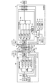
次に、カメラヘッド8、伝送ケーブル9、および、制御装置5の構成について説明する。図2は、内視鏡2のカメラヘッド8、伝送ケーブル9および制御装置5の構成を示すブロック図である。
Next, the configurations of the
カメラヘッド8は、図2に示すように、レンズユニット81と、撮像素子82と、駆動部83と、送信信号処理部84と、E/O変換部85(電光変換部)と、を備える。
As shown in FIG. 2, the
レンズユニット81は、1または複数のレンズを用いて構成され、挿入部7にて集光された被写体像を、撮像素子82の撮像面に結像する。1または複数のレンズは、光軸に沿って移動可能に構成されている。そして、レンズユニット81には、1または複数のレンズを移動させて、画角を変化させる光学ズーム機構(図示略)や焦点を変化させるフォーカス機構(図示略)が設けられている。
The
撮像素子82は、制御装置5による制御のもと、被検体内部を撮像する。撮像素子82は、光が照射された被写体からの光を受光し、受光した光を光電変換して画像信号を生成する複数の画素が行列状に配置された受光部(不図示)と、複数の画素が生成した画像信号(電気信号)を読み出す読み出し部(不図示)と、読み出し部が読み出した画像信号(アナログ)に対してノイズ除去やA/D変換などを行うAFE部(不図示)と、制御装置5から受信した制御信号にしたがって撮像素子82の動作を制御する制御部(不図示)とを有し、デジタルの画像信号を出力する。撮像素子82は、たとえば、水平ラインごとの露光かつ読み出しが可能であるCMOS(Complementary Metal Oxide Semiconductor)撮像素子である。また、撮像素子82は、CCD(Charge Coupled Device)撮像素子であってもよい。撮像素子82が生成した画像信号は、RAW形式のライブ画像信号、あるいは、圧縮率の低い所定形式の画像信号として、送信信号処理部84に出力される。
The
駆動部83は、制御装置5による制御のもと、光学ズーム機構やフォーカス機構を動作させ、レンズユニット81の画角や焦点を変化させる。
Under the control of the
送信信号処理部84は、分配切替部841と、4つのトランスミッタ842〜845とを有する。
The transmission
分配切替部841は、4つの信号伝送路における信号の不良を示す伝送不良情報を制御装置5から受信し、その伝送不良情報に基づいて4つのトランスミッタ842〜845への画像信号の分配方法を切り替えることにより、複数の分配画像信号を生成して出力する。例えば、4つの光ケーブルが全て正常に動作している場合、分配切替部841は4つのトランスミッタに画像信号を分配する。また、m個(m=1,2,3)の信号伝送路で伝送不良が検出された場合、分配切替部841は、その信号伝送路に対応するトランスミッタを除く4−m個のトランスミッタに画像信号を分配する。分配切替部841は、画像信号を分配する数に応じて伝送レートを変更する。この際、分配切替部841は、トータルの伝送レートが分配する数によらず同一となるように分配画像信号の伝送レートを変更する。本実施の形態1において、分配切替部841が分配する画像信号の各々は、パラレル信号である。
The
トランスミッタ842〜845は、分配切替部841から受信した分配画像信号に対してそれぞれ符号化処理およびパラレル/シリアル(P/S)変換処理等を行い、E/O変換部85へ出力する。トランスミッタ842〜845は、例えばNビット/Mビット符号化(N<M)の符号化処理を行う。トランスミッタ842〜845は、入力された分配画像信号に対し、記憶されている変換テーブルをもとに、例えば、8b/10b符号化処理、64b/66b符号化処理または128b/130b符号化処理を施す。トランスミッタ842〜845は、符号化処理した分配画像信号に対し、クロック信号の重畳処理、有効データの開始位置および終了位置へのKコード挿入処理、P/S変換などの処理を施して、E/O変換部85にシリアル出力する。
The
以上説明した送信信号処理部84は、例えば、FPGA(Field Programmable Gate Array)等の専用の集積回路を用いて構成される。
The transmission
E/O変換部85は、トランスミッタ842〜845からそれぞれ入力されたシリアルの分配画像信号を光信号に変換し、変換した各光信号を、対応する光ケーブル91a〜91dに出力する。例えば、4つの画像信号が入力された場合、E/O変換部85は、4つの光信号をそれぞれ対応する4本の光ケーブルに出力する。また、3つの電気信号が入力された場合、E/O変換部85は、3つの光信号をそれぞれ対応する3本の光ケーブルに出力する。E/O変換部85は、例えばレーザダイオード等を用いて構成され、レーザ光等の通信用の光を出射する光出射手段を有する。
The E/
なお、上述した光出射手段は、長時間の駆動に伴う出射光量の低下に起因した光伝送の性能劣化が生じるおそれがある。そこで、医療用観察システム1が光出射手段の交換時期を報知する交換時期報知手段を具備してもよい。交換時期報知手段は、光出射手段への通電時間をカウントする通電時間カウント手段と、この通電時間カウント手段による通電時間情報を格納する不揮発性メモリと、この不揮発性メモリに格納された通電時間情報と、あらかじめ決められた所定の交換時間とを比較する比較手段と、この比較手段により通電時間が交換時間を超えた場合に、その旨を報知する報知手段と、を有する。 Note that the above-described light emitting means may cause performance degradation of optical transmission due to a decrease in the amount of emitted light due to driving for a long time. Therefore, the medical observation system 1 may include a replacement time notification unit that notifies the replacement time of the light emitting unit. The replacement timing informing means includes energization time counting means for counting energization time to the light emitting means, a non-volatile memory for storing energization time information by the energization time counting means, and energization time information stored in the non-volatile memory. And comparison means for comparing a predetermined replacement time with a predetermined replacement time, and notification means for notifying that when the energization time exceeds the replacement time by the comparison means.
報知手段による報知のタイミングは、通電時間が交換時間を超えたタイミングでもよいし、交換時間に所定の時間だけ近づいたタイミングでもよいし、その両方のタイミングでもよい。上述した所定の時間は、報知するタイミングに合わせて適宜設定すればよい。 The timing of the notification by the notification means may be a timing at which the energization time exceeds the replacement time, a timing at which the replacement time is approached by a predetermined time, or both timings. The above-mentioned predetermined time may be set appropriately according to the timing of notification.
また、医療用観察システム1が、通電時間カウント手段の代わりに、光出射手段からの光の少なくとも一部の光量を測定する光量測定手段を具備してもよい。この場合には、その光量が所定値以下となった場合に報知手段が報知するようにすればよい。 Further, the medical observation system 1 may include a light amount measuring unit that measures the light amount of at least a part of the light emitted from the light emitting unit, instead of the energization time counting unit. In this case, the notification means may notify when the amount of light becomes a predetermined value or less.
報知手段による報知を受けた操作者またはサービスマンは、例えば伝送ケーブル9を交換する。なお、交換する部位はこれに限らず、光出射手段自体やE/O変換部85でもよい。また、光出射手段が伝送ケーブル9ではなく、例えばカメラヘッド8に配設されている場合、操作者またはサービスマンはカメラヘッド8を交換する。このようにして、常に性能劣化のない光伝送を実現することが可能となる。
The operator or service person who receives the notification from the notification means replaces the
伝送ケーブル9は、後述する制御装置5のコネクタ50と着脱自在に接続されるコネクタ90(送信側コネクタ)と、4本の光ケーブル91a〜91dで構成される光ケーブル群91と、複数の電気配線92とを有する。
The
光ケーブル91a〜91dは、各先端がそれぞれE/O変換部85に接続するとともに、各基端に光接続部93a〜93d(送信側光接続部)がそれぞれ設けられる。各光接続部93a〜93dは、コネクタ90に設けられる。各光接続部93a〜93dは、それぞれ対応する各光ケーブル91a〜91dの光ファイバ端面と接続するGRINレンズと、このGRINレンズ表面を覆うカバーガラスとを有する。
Each of the
制御装置5は、コネクタ50(受信側コネクタ)と、複数の光ケーブル51a〜51dで構成される光ケーブル群51と、O/E変換部52(光電変換部)と、受信信号処理部53と、画像処理部54と、表示制御部55と、制御部56と、入力部57と、出力部58と、記憶部59と、埃検知部60と、を備える。
The
コネクタ50は、光接続部50a〜50d(受信側光接続部)を有し、各光接続部50a〜50dからは、それぞれ対応する光ケーブル51a〜51dが延伸する。光接続部50a〜50dは、それぞれ対応する光ケーブル51a〜51dの入力側端部である先端に設けられ、外部部材である伝送ケーブル9のコネクタ90における光接続部93a〜93dと分離可能に接続する。各光接続部50a〜50dは、光ケーブル51a〜51dの光ファイバ端面と接続するGRINレンズと、このGRINレンズ表面を覆うカバーガラスとを有する。光接続部50X(X=a,b,c,d。以下、同じ文字が対応)と伝送ケーブル9側の光接続部93Xとは、互いの接続面同士が接触することによって、光ケーブル91Xと光ケーブル51Xとを接続する。光ケーブル51X、91X、および光接続部50X、93Xは、1つの信号伝送路を構成する。なお、本実施の形態1において、信号伝送路の数は4つに限られるわけではなく、2つ、3つまたは5つ以上でもよい。
The
光ケーブル51a〜51dは、それぞれ対応する光接続部50a〜50dに入力された光信号を伝送し、伝送した光信号をO/E変換部52に入力する。
The
O/E変換部52は、光ケーブル51a〜51dによって伝送された複数の光信号のそれぞれを複数のシリアル電気信号に変換し、受信信号処理部53に入力する。
The O/
受信信号処理部53は、O/E変換部52によって変換されたシリアル電気信号をそれぞれ受信する4つのレシーバ531〜534と、レシーバ531〜534の受信状況をもとに伝送不良を検出する伝送不良検出部535と、レシーバ531〜534がそれぞれ出力した信号を統合して出力する統合部536と、を有する。
The reception signal processing unit 53 includes four
レシーバ531〜534は、O/E変換部52から受信したシリアル信号に重畳されたクロック信号を再生するクロックデータリカバリー(CDR)処理、CDR処理後のシリアル信号をパラレル信号に変換するS/P変換処理、S/P変換後のパラレル信号からKコードを検出して有効データを取得するKコード検出処理、S/P変換後のパラレル信号から誤ったデータを受信する確率を算出するビットエラーレート(BER)検出処理、およびKコード検出処理後のパラレル信号に対してMビット/Nビット変換(復号化)を行う復号化処理を実行する。レシーバ531〜534は、CDR処理、Kコード検出処理およびBER検出処理の実行結果を伝送不良検出部535へそれぞれ出力する。
The
伝送不良検出部535は、レシーバ531〜534がそれぞれ実行したCDR処理、Kコード検出処理、およびBER検出処理の実行結果をもとに、複数の信号伝送路における光信号の伝送不良の有無を検出するとともに、伝送不良を生じた信号伝送路を特定する。伝送不良検出部535は、伝送不良情報を制御部56に出力する。伝送不良情報には、少なくとも伝送不良を生じた信号伝送路を示す情報が含まれる。
The transmission
統合部536は、レシーバ531〜534がそれぞれ出力したパラレル電気信号を用いてカメラヘッド8の分配切替部841が行う処理と逆の処理を実行することにより、複数の電気信号を統合する。統合部536は、レシーバ531〜534のうち受信したパラレル電気信号の数に応じて統合処理を行う。なお、4つの信号伝送路のいずれかに伝送不良が生じた場合、統合部536が統合する信号には、伝送不良が生じた分の画像データが失われる欠損が発生する。
The
以上説明した受信信号処理部53は、例えば、送信信号処理部84と同様に、FPGA等の専用の集積回路を用いて構成されている。
The reception signal processing unit 53 described above is configured using a dedicated integrated circuit such as an FPGA, similar to the transmission
画像処理部54は、後述する制御部56の制御のもと、受信信号処理部53から出力された画像信号、すなわち、撮像素子82によって生成されたRAW形式あるいは圧縮率の低い所定形式の画像信号に対し、所定の信号処理を行う。画像処理部54は、この画像信号に対して、オプティカルブラック減算処理、ゲイン調整処理、画像信号の同時化処理、ガンマ補正処理、ホワイトバランス(WB)調整処理、カラーマトリクス演算処理、色再現処理およびエッジ強調処理等を含む各種画像処理を行う。
Under the control of the
表示制御部55は、画像処理部54が処理した画像信号から、表示装置6に表示させるための表示用画像信号を生成する。表示装置6に出力される表示用画像信号は、例えば、SDI,DVI(登録商標)、HDMI(登録商標)形式等のデジタル信号である。表示制御部55は、伝送不良検出部535が信号伝送路の伝送不良を検出した場合には、制御部56の制御のもと、信号伝送路に伝送不良が生じた旨を示すアラーム画像信号を生成し、表示装置6に表示出力させる。また、表示制御部55は、埃検知部60によって検知された埃の蓄積量が一定の閾値を超えた場合には、制御部56の制御のもと、機内温度の異常上昇が発生するおそれがある旨を示すアラーム画像信号を生成し、表示装置6に表示出力させる。
The display control unit 55 generates a display image signal to be displayed on the
制御部56は、例えば、CPU等を用いて実現される。制御部56は、制御装置5の各部の処理動作を制御する。制御部56は、制御装置5の各部に対する指示情報やデータの転送等を行うことによって、制御装置5の動作を制御する。制御装置5は、各ケーブルを介してカメラヘッド8の各構成部位に接続されており、撮像素子82、駆動部83等の動作についても制御を行う。制御部56は、カメラヘッド8の分配切替部841が行う分配切替処理も制御する。
The
制御部56は、伝送不良検出部535における検出結果に応じて、送信信号処理部84が出力する電気信号の数を変更する。制御部56は、伝送不良検出部535によって複数の信号伝送路のうち伝送不良を生じた信号伝送路が特定された場合、伝送不良を生じた信号伝送路以外の信号伝送路に複数の光信号が分配されるように、送信信号処理部84が出力する分配画像信号の数を変更する分配切替制御信号を生成してカメラヘッド8の送信信号処理部84へ送信する。
The
入力部57は、マウス、キーボードおよびタッチパネル等の操作デバイスを用いて実現され、医療用観察システム1の各種指示情報の入力を受け付ける。具体的には、入力部57は、被検体情報(例えばID、生年月日、名前等)、内視鏡2の識別情報(例えばIDや検査対応項目)および検査内容等の各種指示情報の入力を受け付ける。
The
出力部58は、たとえば、スピーカーやプリンタ等を用いて実現され、体内観察に関する各種情報を出力する。出力部58は、制御部56の制御のもと、伝送不良検出部535が伝送不良を検出した場合には、伝送不良が生じた旨を示すアラーム音声を出力する。また、出力部58は、制御部56の制御のもと、埃検知部60によって検知された埃の蓄積量が一定の閾値を超えた場合には、機内温度の異常上昇が発生するおそれがある旨を示すアラーム音声を出力する。
The
記憶部59は、RAM(Random Access Memory)等の揮発性メモリやROM(Read Only Memory)等の不揮発性メモリを用いて実現され、カメラヘッド8や制御装置5等を動作させるための各種プログラムを記憶する。記憶部59は、制御装置5の処理中の情報を一時的に記録する。記憶部59は、撮像素子82によって撮像された画像信号、および、画像処理部54によって画像処理が行われた画像信号を記憶する。記憶部59は、制御装置5の外部から装着されるメモリカード等を用いて構成されてもよい。
The
埃検知部60は、制御装置5内部の埃の蓄積を検知して、検知結果を制御部56に出力する。制御部56は、埃検知部60によって検知された埃の蓄積量が所定の閾値を超えた場合には、ファンロックが発生したおそれや、埃の蓄積による回路のショートや風量の減少によって機内温度の異常上昇が発生するおそれがある旨を示すアラーム情報を、表示装置6または出力部58に出力させる。
The
図3は、制御装置5の内部の一部を示す斜視図である。埃検知部60は、例えばフローセンサであり、制御装置5のファン601の吹き出し口側のフィルタ602外側に複数(図3では2つ)設けられる。図4は、図3に示す制御装置5の内部の一部の右側面図である。埃検知部60は、図4の矢印に示すようにファン601から外部へ吹き出される風の風量を検知する。フィルタ602に埃が蓄積すると風量が減る。そこで、埃検知部60が検知した風量値が一定の閾値を下回った場合、制御部56は、アラーム情報の出力制御処理を行う。
FIG. 3 is a perspective view showing a part of the inside of the
なお、埃検知部60は、光学的に埃を検知する光学センサでもよい。この場合、埃検知部60を埃がたまりやすい場所に設置し、検知した埃量が閾値を上回ったときには、制御部56は、アラーム情報の出力制御処理を行う。また、埃検知部60は、埃検知専用の回路でもよい。この回路が埃によってショートした場合、制御部56は、アラーム情報の出力制御処理を行う。また、埃検知部60をファン601およびフィルタ602の少なくともいずれかの一方の近くに設けるほか、埃が溜まりやすい筐体の角部等に設けてもよい。なお、図3および図4では、埃検知部60を2つ設置した例を示しているが、設置する数は単数でもよいし、3つ以上でもよい。
The
次いで、図2に示す制御装置5における伝送不良検出処理について説明する。図5は、図2に示す制御装置5における伝送不良検出処理の処理手順を示すフローチャートである。
Next, the transmission failure detection process in the
図5に示すように、まず、伝送不良検出部535は、レシーバ531〜534からCDR処理結果を取得し(ステップS1)、各レシーバがCDR処理を実行できたか否かを判断する(ステップS2)。光ファイバ断線時には、該断線した光ファイバを有する光ケーブルからは、受信側の制御装置5に光信号自体が入力されないため、CDR処理も実行されない。このため、伝送不良検出部535は、CDR処理を実行できなかったレシーバがある場合には(ステップS2:No)、そのレシーバに対応する信号伝送路において断線等に起因する伝送不良が生じたことを検出する(ステップS3)。
As shown in FIG. 5, first, the transmission
伝送不良検出部535は、全てのレシーバがCDR処理を実行できたと判断した場合には(ステップS2:Yes)、レシーバ531〜534からKコード検出処理結果を取得する(ステップS4)。伝送不良検出部535は、取得したKコード検出処理結果をもとに、各レシーバがKコードを検出できたか否かを判断する(ステップS5)。光ファイバ断線時には、該断線した光ファイバを有する光ケーブルからは、受信側の制御装置5に光信号自体が入力されないため、Kコードの検出やデータのタイミング検出も実行されない。このため、伝送不良検出部535は、Kコードを検出できなかったレシーバがある場合には(ステップS5:No)、そのレシーバに対応する信号伝送路に伝送不良が生じたことを検出する(ステップS3)。
When determining that all the receivers have been able to execute the CDR processing (step S2: Yes), the transmission
伝送不良検出部535は、全てのレシーバがKコードを検出できたと判断した場合には(ステップS5:Yes)、レシーバ531〜534からBER検出処理結果を取得する(ステップS6)。伝送不良検出部535は、取得したBER検出処理結果をもとに、各レシーバのビットエラーレートが所定の閾値を超えた高ビットエラーレートであるか否かを判断する(ステップS7)。光ケーブルに伝送不良および伝送劣化が生じた場合には、O/E変換部52に入力される光信号の光強度が弱くなり、BER検出処理で検出されるビットエラーレートも高くなる。このため、伝送不良検出部535は、全てのレシーバからのBER検出処理結果におけるビットエラーレートが高ビットエラーレートではない場合には(ステップS7:No)、伝送不良はないと判断し(ステップS8)、この伝送不良検出処理を終了する。
When the transmission
これに対し、伝送不良検出部535は、BER検出処理の結果、高ビットエラーレートであるレシーバがある場合には(ステップS7:Yes)、そのレシーバに対応する信号伝送路に伝送不良が生じたことを検出する(ステップS3)。
On the other hand, if there is a receiver having a high bit error rate as a result of the BER detection processing (step S7: Yes), the transmission
ステップS3の後の処理を説明する。制御部56は、伝送不良検出部535によって特定された光ケーブル以外の光ケーブルに対応するトランスミッタへ画像信号を分配するための分配切替制御信号を送信信号処理部84へ送信する(ステップS9)。
The process after step S3 will be described. The
制御部56は、伝送不良が生じたことを示すアラーム情報を、表示装置6、出力部58に出力させる伝送不良出力処理を行う(ステップS10)。このアラーム情報は、伝送不良が生じた信号伝送路を特定して示すとともに、伝送不良の回復方法についても示す。たとえば、CDR処理不実行或いはKコード検出処理が不実行であった信号伝送路については、光ファイバが断線している可能性が高いため、検査終了後に光ケーブルの交換等のメンテナンスを推奨するメッセージを出力する。また、BER検出処理で高ビットエラーレートが検出された信号伝送路については、コネクタの光接続部に汚れや曇りがある可能性あるため、検査終了後に光接続部の清掃を推奨するメッセージを出力する。そして、この場合には、光接続部の光軸ずれが生じた場合も考えられるため、光軸修正を推奨するメッセージも出力する。
The
例えば、制御装置5では、検査中においても、ステップS1〜ステップS10の処理を行うほか、使用前点検時および検査終了時にステップS1〜ステップS10の処理を行ってもよい。
For example, the
このように、実施の形態1では、手技中に光ケーブルのいずれかに伝送不良が生じた場合であっても、伝送不良が生じていない他の3つの信号伝送路に切り替えられるため、制御装置5への光信号(画像信号)の伝送はそのまま継続される。このため、実施の形態1では、例えば、手技中に信号伝送路に伝送不良が発生した場合であっても、手技中における突然の画像消失を確実に回避でき、手技を適切に継続することができる。また、実施の形態1では、光接続部の汚れや、光軸ずれ、経年劣化による通信不良があった場合であっても、伝送不良による画像ノイズを防止し、ノイズのない明確な画像表示を継続できる。また、実施の形態1では、光接続部の伝送不良を検出した場合にはアラーム情報が出力されるため、伝送不良が放置されることもない。
As described above, in the first embodiment, even if a transmission failure occurs in one of the optical cables during the procedure, the
図6は、制御装置5の筐体内部の要部における平面図の一例である。図7は、図6に示す筐体を筐体内の基板の基板面に鉛直な面で切断した図である。図6および図7に示すように、制御装置5の筐体内部に設けられる基板603には、撮像等の種々の処理を実行するためのデバイスが接続しており、各デバイスは、駆動すると熱を発するのが一般的である。このため、通常は、ファン等を設けて発熱デバイスを冷却しているものの、ファンロックが発生した場合には、基板上のデバイスが発熱で故障するおそれがある。そこで、実施の形態1では、チップごとに専用のファンを設ける代わりに、複数のデバイス604、605を熱伝導性の高い部材であるヒートシンク606で接続し、ヒートシンク606上に設けられたファン601を含む筐体607内の複数のファン601を用いてヒートシンク606を冷却することによって、ファンロックのような冷却手段の単一故障のリスクを回避している。また、ファンロック等の単一故障が発生した場合、制御部56は、アラーム情報の出力制御処理を行う。
FIG. 6 is an example of a plan view of the main part inside the housing of the
なお、上述した冷却手段自体は、カメラヘッド8に対しても適用可能である。カメラヘッド8に適用する場合は、ファンによる冷却ではなく、筐体等に伝熱させ放熱することによって冷却を行うのが好ましい。また、カメラヘッド8の内部で異常な発熱が生じた場合は、その旨をカメラヘッド8から制御装置5に報知する。
The cooling means itself described above is also applicable to the
なお、伝送不良検出部535が4つの信号伝送路のうちの1つに対して伝送不良を検出した場合には、残りの3つの信号伝送路を全て使用する代わりに、所定の2つの信号伝送路を介して光信号を伝送してもよい。
When the transmission
(実施の形態1の変形例1−1)
図8は、実施の形態1の変形例1−1に係る内視鏡のカメラヘッド、伝送ケーブルおよび制御装置の構成を示すブロック図である。図8では、図2に示す構成と比して、伝送ケーブル9Aのコネクタ90AがO/E変換部52を有し、制御装置5AがO/E変換部52を有しない。光ケーブル91a〜91dによってそれぞれ伝送された光信号は、コネクタ90AのO/E変換部52において電気信号に変換されて、4本の電気配線51Aを介して受信信号処理部53に出力される。したがって、図8に示す構成によれば、複数の信号伝送路の途上にO/E変換部52を設けることにより、コネクタ90Aおよび制御装置5A側のコネクタ50Aに、光接続部93a〜93d,50a〜50dを設けなくてもよい。
(Modification 1-1 of Embodiment 1)
FIG. 8 is a block diagram showing the configurations of the camera head, the transmission cable, and the control device of the endoscope according to the modified example 1-1 of the first embodiment. In FIG. 8, compared to the configuration shown in FIG. 2, the
この図8に示す構成のように、伝送ケーブル9A側のコネクタ90AにO/E変換部52を設けた場合には、伝送ケーブル9Aから制御装置5Aに対して、電気配線を用いて信号を伝送できるため、光接続部の光軸ずれや、光接続部の接続面の汚れや曇り等に起因する伝送不良、画像ノイズを抑制することが可能になる。
When the
(実施の形態2)
次に、実施の形態2について説明する。実施の形態2では、光ケーブル群に、予備の光ケーブルを設け、通常使用する光ケーブルのいずれかに伝送不良が生じた場合には、伝送不良が生じた光ケーブルに代えて、予備の光ケーブルを用いて光信号の伝送処理を行う。
(Embodiment 2)
Next, a second embodiment will be described. In the second embodiment, a spare optical cable is provided in the optical cable group, and when a transmission failure occurs in any of the normally used optical cables, the spare optical cable is used instead of the optical cable in which the transmission failure occurs. Performs signal transmission processing.
図9は、実施の形態2に係る内視鏡のカメラヘッド、伝送ケーブルおよび制御装置の構成を示すブロック図である。図9に示すように、実施の形態2における伝送ケーブル209は、光ケーブル群291として、通常使用する3本の光ケーブル91a〜91cに加え、予備の光ケーブル291dを有する。予備の光ケーブル291dは、E/O変換部85が変換した複数の光信号の少なくともいずれか一つを伝送可能である。伝送ケーブル209では、従来使用されていた支持材の代わりに、予備の光ケーブル291dを通して他の光ケーブル91a〜91c間の隙間を埋めている。そして、制御装置5側の光ケーブル群251も、通常使用する3本の光ケーブル51a〜51cに加え、予備の光ケーブル251dを有する。光ケーブル51Y(Y=a,b,c。以下、同じ文字が対応)、91Y、および光接続部50Y、93Yは、通常使用する1つの信号伝送路を構成する。また、光ケーブル51d、91d、および光接続部50d、93dは、予備の信号伝送路を構成する。なお、本実施の形態2において、通常使用する信号伝送路の数は2つまたは4つ以上でもよいし、予備の信号伝送路の数は2つ以上でもよい。
FIG. 9 is a block diagram showing the configurations of the camera head, the transmission cable, and the control device of the endoscope according to the second embodiment. As shown in FIG. 9, the
実施の形態2におけるカメラヘッド208は、送信信号処理部284を有する。送信信号処理部284は、分配切替部2841と、4つのトランスミッタ842〜845とを有する。送信信号処理部284は、本発明に係る医療用信号処理装置として機能する。
The
分配切替部2841は、制御装置5から信号伝送路の伝送不良情報を受信し、その伝送不良情報に基づいて4つのトランスミッタ842〜845への画像信号の分配方法を切り替えることにより、複数の分配画像信号を生成して出力する。例えば、全ての信号伝送路の伝送状態が正常である場合、分配切替部2841は、撮像素子82から出力された画像信号を、通常使用される3つの信号伝送路にそれぞれ対応する3つのトランスミッタ842〜844に分配する。3つの信号伝送路は、光ケーブル91a〜91cをそれぞれ有する。3つの信号伝送路のうちn個(n=1,2)の信号伝送路で伝送不良が検出された場合、分配切替部2841は、その信号伝送路に対応するトランスミッタを除く3−n個のトランスミッタ、および予備の信号伝送路(光ケーブル291dを含む)に対応するトランスミッタ845に対して画像信号を分配する。本実施の形態2においても、分配切替部2841が分配する画像信号の各々は、パラレル信号である。
The
実施の形態2において、制御装置5の受信信号処理部53には、最大3つのシリアル電気信号が光ケーブル群251から入力される。
In the second embodiment, a maximum of three serial electric signals are input from the
実施の形態2において、伝送不良検出部535が、例えば通常使用する信号伝送路のうち光ケーブル91aを含む信号伝送路に伝送不良を検出した場合、制御部56は、カメラヘッド208の分配切替部2841に対し、光ケーブル91aに対応するトランスミッタ842への分配を停止する一方、トランスミッタ843、844に加えて予備の信号伝送路に対応するトランスミッタ845へ分配させる分配切替制御信号を送信する。
In the second embodiment, when the transmission
このように、実施の形態2では、手技中に、3つの信号伝送路のいずれかに伝送不良が生じた場合であっても、伝送不良が生じていない予備の信号伝送路を経由する伝送経路に切り替えられ、光信号の伝送はそのまま継続されるため、実施の形態1と同様の効果を奏する。 As described above, in the second embodiment, even if a transmission failure occurs in any of the three signal transmission paths during the procedure, the transmission path passing through the backup signal transmission path in which the transmission failure does not occur. The optical signal transmission is continued as it is, so that the same effect as that of the first embodiment is obtained.
なお、伝送不良検出部535は、3つの信号伝送路のうちの1つに対して伝送不良を検出した場合、残りの2つの信号伝送路を全て使用する代わりに、所定の1つの信号伝送路を用いるようにしてもよい。
When the transmission
(実施の形態2の変形例2−1)
図10は、実施の形態2の変形例2−1に係る内視鏡のカメラヘッド、伝送ケーブルおよび制御装置の構成を示すブロック図である。図10に示すように、実施の形態2の変形例2−1においては、実施の形態1の変形例1−1に示す構成と同様に、伝送ケーブル209Aのコネクタ90AがO/E変換部52を有し、制御装置5AはO/E変換部52を有しない。この場合も、実施の形態1の変形例1−1と同様に、伝送ケーブル209Aから制御装置5Aに対して、電気配線を用いて信号を伝送できるため、光接続部の光軸ずれや、光接続部の接続面の汚れや曇り等に起因する伝送不良、画像ノイズを抑制することが可能になる。
(Modification 2-1 of Embodiment 2)
FIG. 10 is a block diagram showing a configuration of a camera head, a transmission cable, and a control device of an endoscope according to a modification 2-1 of the second embodiment. As shown in FIG. 10, in the modification 2-1 of the second embodiment, the
(実施の形態3)
次に、本発明の実施の形態3について説明する。以下の説明では、上述した実施の形態1、2と同様の構成には同一符号を付し、その詳細な説明は省略または簡略化する。上述した実施の形態1、2に係る医療用観察システム1では、カメラヘッド8を用いた内視鏡2に本発明を適用していた。これに対して、本実施の形態3に係る医療用観察システムでは、内視鏡の挿入部の先端側に撮像部を有する所謂ビデオスコープに本発明を適用している。
(Embodiment 3)
Next, a third embodiment of the invention will be described. In the following description, the same components as those in the first and second embodiments described above are designated by the same reference numerals, and detailed description thereof will be omitted or simplified. In the medical observation system 1 according to the first and second embodiments described above, the present invention is applied to the
図11は、本発明の実施の形態3に係る医療用観察システムの概略構成を示す図である。本実施の形態3に係る医療用観察システム1Aは、図11に示すように、生体内に挿入部7Aを挿入することによって観察部位の体内画像を撮像して画像信号を生成するとともに、当該画像信号から複数の送信用画像信号を生成する内視鏡2Aと、内視鏡2Aの先端から出射する照明光を発生する光源装置3と、内視鏡2Aにて生成された複数の送信用画像信号を入力し、当該複数の送信用画像信号を処理する制御装置5(上述した実施の形態1または実施の形態2で説明した制御装置)と、制御装置5にて処理された映像信号に基づく画像を表示する表示装置6とを備える。
FIG. 11: is a figure which shows schematic structure of the medical observation system which concerns on
内視鏡2Aは、図11に示すように、可撓性を有する細長形状をなす挿入部7Aと、挿入部7Aの基端側に接続され、各種の操作信号の入力を受け付ける操作部8Aと、操作部8Aから挿入部7Aが延びる方向と異なる方向に延び、光源装置3および制御装置5に接続する各種ケーブルを内蔵するユニバーサルコード10Aとを備える。
As shown in FIG. 11, the
挿入部7Aは、図11に示すように、生体内を撮像して画像信号を生成する撮像部(図示略)を内蔵した先端部71と、複数の湾曲駒によって構成された湾曲自在な湾曲部72と、湾曲部72の基端側に接続され、可撓性を有する長尺状の可撓管部73とを備える。
As shown in FIG. 11, the
そして、操作部8A内部には、具体的な図示は省略したが、上述した実施の形態1で説明した送信信号処理部84およびE/O変換部85と同様の構成が内蔵され、上述した撮像部にて生成された画像信号を当該送信信号処理部にて処理する。また、ユニバーサルコード10Aは、上述した実施の形態1で説明したライトガイド4および伝送ケーブル9とそれぞれ略同様の構成を含む。そして、操作部8A内部(送信信号処理部および電光変換部)にて処理(生成)された複数の送信用画像信号(光信号)は、ユニバーサルコード10Aを介して、制御装置5に出力される。
Although not specifically shown, the
以上説明した本実施の形態3のように軟性内視鏡(内視鏡2A)を用いた場合であっても、上述した実施の形態1と同様の効果を奏する。
Even when the flexible endoscope (
(実施の形態4)
次に、本発明の実施の形態4について説明する。以下の説明では、上述した実施の形態1、2と同様の構成には同一符号を付し、その詳細な説明は省略または簡略化する。上述した実施の形態1,2に係る医療用観察システム1では、カメラヘッド8を用いた内視鏡2に本発明を適用していた。これに対して、本実施の形態4に係る医療用観察システムでは、被検体内(生体内)や被検体表面(生体表面)の所定の視野領域を拡大して撮像する手術用顕微鏡に本発明を適用している。
(Embodiment 4)
Next, a fourth embodiment of the invention will be described. In the following description, the same components as those in the first and second embodiments described above are designated by the same reference numerals, and detailed description thereof will be omitted or simplified. In the medical observation system 1 according to
図12は、本発明の実施の形態4に係る医療用観察システムの概略構成を示す図である。本実施の形態4に係る医療用観察システム1Bは、図12に示すように、被写体を観察するための画像を撮像して画像信号を生成するとともに、当該画像信号から複数の送信用画像信号を生成する手術用顕微鏡2Bと、手術用顕微鏡2Bにて生成された複数の送信用画像信号を入力し、当該複数の送信用画像信号を処理する制御装置5(上述した実施の形態1または実施の形態2で説明した制御装置)と、制御装置5にて処理された映像信号に基づく画像を表示する表示装置6とを備える。
FIG. 12 is a diagram showing a schematic configuration of the medical observation system according to the fourth embodiment of the present invention. As shown in FIG. 12, the
手術用顕微鏡2Bは、図12に示すように、被写体の微小部位を拡大して撮像し、画像信号を生成するとともに、当該画像信号から複数の送信用画像信号を生成する顕微鏡部21と、顕微鏡部21の基端部に接続し、顕微鏡部21を回動可能に支持するアームを含む支持部22と、支持部22の基端部を回動可能に保持し、床面上を移動可能なベース部23とを備える。そして、制御装置5は、図12に示すように、ベース部23に設置されている。なお、ベース部23は、床面上に移動可能に設けるのではなく、天井や壁面等に固定して支持部22を支持する構成としてもよい。また、ベース部23は、手術用顕微鏡2Bから被写体に照射する照明光を生成する光源部を備えていてもよい。
As shown in FIG. 12, the operating
顕微鏡部21は、具体的な図示は省略したが、生体内や生体表面を撮像して画像信号を生成する撮像部と、上述した実施の形態1で説明した送信信号処理部84およびE/O変換部85と同様の構成とが内蔵され、当該撮像部にて生成された画像信号を当該送信信号処理部にて処理する。そして、顕微鏡部21(送信信号処理部および電光変換部)にて処理(生成)された複数の送信用画像信号(光信号)は、支持部22に沿って支持部22の内部に配線された伝送ケーブル9を介して、制御装置5に出力される。
Although not specifically shown, the
以上説明した本実施の形態4のように手術用顕微鏡2Bを用いた場合であっても、上述した実施の形態1と同様の効果を奏する。
Even when the
なお、本発明において、カメラヘッドの送信信号処理部が有する分配切替部の分配切替制御をカメラヘッド側が行ってもよい。この場合、カメラヘッドは、制御装置から受信する伝送不良検出情報に基づいて、分配切替部の分配切替制御を行う。 In the present invention, the camera head side may perform the distribution switching control of the distribution switching unit included in the transmission signal processing unit of the camera head. In this case, the camera head controls the distribution switching of the distribution switching unit based on the transmission failure detection information received from the control device.
また、本発明において、複数の信号伝送路が電気信号をそれぞれ伝送する構成としてもよい。この場合には、上述した光ケーブル、光接続部、E/O変換部およびO/E変換部が不要となり、電気配線および電気配線を接続する接続部を用いて複数の信号伝送路が構成される。 Further, in the present invention, a plurality of signal transmission paths may respectively transmit electric signals. In this case, the above-mentioned optical cable, optical connection part, E/O conversion part, and O/E conversion part are unnecessary, and a plurality of signal transmission lines are configured using the electrical wiring and the connection part for connecting the electrical wiring. ..
また、本発明に係る医療用観察システムは、上述した内視鏡の代わりに、超音波プローブを用いて構成した超音波内視鏡を備えても構わない。 Further, the medical observation system according to the present invention may include an ultrasonic endoscope configured by using an ultrasonic probe instead of the above-described endoscope.
上述したカメラヘッドや制御装置における各処理を実行させるためのプログラムは、インストール可能な形式または実行可能な形式のファイルでCD−ROM、フレキシブルディスク、CD−R、DVD等のコンピュータで読み取り可能な記録媒体に記録して提供してもよい。また、上述したプログラムを、インターネット等のネットワークに接続されたコンピュータ上に格納し、ネットワーク経由でダウンロードさせることにより提供してもよいし、インターネット等のネットワーク経由で提供または配布してもよい。 A program for executing each process in the above-described camera head and control device is a file in an installable format or an executable format, and is a computer-readable record such as a CD-ROM, a flexible disk, a CD-R, a DVD. It may be recorded on a medium and provided. Further, the above program may be provided by being stored in a computer connected to a network such as the Internet and being downloaded via the network, or may be provided or distributed via the network such as the Internet.
1、1A、1B 医療用観察システム
2、2A 内視鏡
2B 手術用顕微鏡
3 光源装置
4 ライトガイド
5、5A 制御装置
6 表示装置
7、7A 挿入部
8、208 カメラヘッド
9、9A、209、209A 伝送ケーブル
10A ユニバーサルコード
21 顕微鏡部
22 支持部
23 ベース部
50、50A、90、90A コネクタ
50a〜50d、93a〜93d 光接続部
51、91、251、291 光ケーブル群
51a〜51d、91a〜91d、251d、291d 光ケーブル
52 O/E変換部
53 受信信号処理部
54 画像処理部
55 表示制御部
56 制御部
57 入力部
58 出力部
59 記憶部
60 埃検知部
71 先端部
72 湾曲部
73 可撓管部
81 レンズユニット
82 撮像素子
83 駆動部
84、284 送信信号処理部
85 E/O変換部
91 光ケーブル群
92 電気配線
531〜534 レシーバ
535 伝送不良検出部
536 統合部
601 ファン
602 フィルタ
603 基板
604、605 デバイス
606 ヒートシンク
607 筐体
841、2841 分配切替部
842〜845 トランスミッタ
1, 1A, 1B
Claims (7)
前記複数の信号伝送路における信号の伝送不良を示す伝送不良情報に基づいて前記画像信号を分配することによって複数の送信用画像信号を生成する送信信号処理部を備え、
前記送信信号処理部は、
前記複数の信号伝送路に伝送不良が生じていないときには、前記複数の信号伝送路のすべてに前記送信用画像信号を伝送させるように前記画像信号を分配し、
前記複数の信号伝送路に伝送不良が生じたときには、前記伝送不良を生じた信号伝送路以外の信号伝送路に前記送信用画像信号を伝送させるように前記画像信号を分配し、
伝送される前記複数の送信用画像信号のトータルの伝送レートが分配の数によらず同一となるように、前記画像信号を分配する数に応じて伝送レートを変更して、前記画像信号を分配することを特徴とする医療用信号処理装置。 A medical signal processing device, which is communicably connected to a medical control device via a plurality of signal transmission paths, and which processes an image signal according to a test result inside a subject,
A transmission signal processing unit for generating a plurality of transmission image signals by distributing the image signals based on transmission failure information indicating transmission failure of signals in the plurality of signal transmission paths,
The transmission signal processing unit,
When no transmission failure occurs in the plurality of signal transmission paths, the image signal is distributed so that the transmission image signal is transmitted to all of the plurality of signal transmission paths,
When a transmission failure occurs in the plurality of signal transmission paths, the image signal is distributed so that the transmission image signal is transmitted to a signal transmission path other than the signal transmission path in which the transmission failure has occurred,
The image signals are distributed by changing the transmission rate according to the number of distributions of the image signals so that the total transmission rate of the plurality of transmission image signals to be transmitted is the same regardless of the number of distributions. A medical signal processing device characterized by:
前記医療用信号処理装置からの前記複数の送信用画像信号をそれぞれ伝送する複数の信号伝送路と、
前記複数の信号伝送路における信号の伝送不良を検出するとともに、前記複数の信号伝送路を介して伝送される前記複数の送信用画像信号に基づいて前記画像信号を復元する受信信号処理部を有する医療用制御装置と、
を備え、
前記医療用信号処理装置および前記医療用制御装置のいずれかは、
前記受信信号処理部における前記伝送不良の検出結果に基づいて前記送信信号処理部による前記画像信号の分配を制御する制御部を有することを特徴とする医療用観察システム。 A medical signal processing apparatus according to claim 1 or 2 ,
A plurality of signal transmission paths for respectively transmitting the plurality of transmission image signals from the medical signal processing device,
A reception signal processing unit that detects a signal transmission failure in the plurality of signal transmission paths and restores the image signal based on the plurality of transmission image signals transmitted through the plurality of signal transmission paths. Medical control device,
Equipped with
Either of the medical signal processing device and the medical control device,
A medical observation system comprising: a control unit that controls distribution of the image signal by the transmission signal processing unit based on a detection result of the transmission failure in the reception signal processing unit.
前記複数の送信用画像信号に基づく複数の電気信号を複数の光信号にそれぞれ変換し、当該複数の光信号を前記複数の信号伝送路にそれぞれ出力する電光変換部をさらに有し、
前記信号伝送路は、
光信号を伝送する光ケーブルを有することを特徴とする請求項3に記載の医療用観察システム。 The medical signal processing device,
A plurality of electric signals based on the plurality of transmission image signals are respectively converted into a plurality of optical signals, further comprising an electro-optical conversion unit that outputs the plurality of optical signals to the plurality of signal transmission paths,
The signal transmission path is
The medical observation system according to claim 3 , further comprising an optical cable that transmits an optical signal.
前記複数の光信号を複数の電気信号にそれぞれ変換する光電変換部をさらに有することを特徴とする請求項4に記載の医療用観察システム。 The medical control device,
The medical observation system according to claim 4 , further comprising a photoelectric conversion unit that converts each of the plurality of optical signals into a plurality of electric signals.
複数の前記光ケーブルと、
前記複数の光信号を複数の電気信号にそれぞれ変換する光電変換部と、
前記複数の電気信号をそれぞれ伝送する複数の電気配線と、
を有することを特徴とする請求項4に記載の医療用観察システム。 The plurality of signal transmission lines,
A plurality of the optical cables,
A photoelectric conversion unit that converts each of the plurality of optical signals into a plurality of electric signals,
A plurality of electric wirings respectively transmitting the plurality of electric signals,
The medical observation system according to claim 4 , further comprising:
Priority Applications (1)
| Application Number | Priority Date | Filing Date | Title |
|---|---|---|---|
| US15/083,488 US10405733B2 (en) | 2015-04-30 | 2016-03-29 | Medical signal processing device and medical observation system |
Applications Claiming Priority (2)
| Application Number | Priority Date | Filing Date | Title |
|---|---|---|---|
| JP2015093675 | 2015-04-30 | ||
| JP2015093675 | 2015-04-30 |
Publications (2)
| Publication Number | Publication Date |
|---|---|
| JP2016209542A JP2016209542A (en) | 2016-12-15 |
| JP6721994B2 true JP6721994B2 (en) | 2020-07-15 |
Family
ID=57550327
Family Applications (1)
| Application Number | Title | Priority Date | Filing Date |
|---|---|---|---|
| JP2016020284A Active JP6721994B2 (en) | 2015-04-30 | 2016-02-04 | Medical signal processing device and medical observation system |
Country Status (1)
| Country | Link |
|---|---|
| JP (1) | JP6721994B2 (en) |
Families Citing this family (2)
| Publication number | Priority date | Publication date | Assignee | Title |
|---|---|---|---|---|
| JP2017202007A (en) * | 2016-05-09 | 2017-11-16 | Hoya株式会社 | Electronic endoscope device |
| WO2018163500A1 (en) * | 2017-03-10 | 2018-09-13 | ソニー・オリンパスメディカルソリューションズ株式会社 | Endoscope device |
Family Cites Families (5)
| Publication number | Priority date | Publication date | Assignee | Title |
|---|---|---|---|---|
| JP2006181021A (en) * | 2004-12-27 | 2006-07-13 | Media Technology:Kk | Electronic endoscope apparatus |
| JP2010161750A (en) * | 2009-01-09 | 2010-07-22 | Sony Corp | Signal transmission apparatus, signal reception device, and signal transmission system |
| JP5642484B2 (en) * | 2010-09-30 | 2014-12-17 | オリンパス株式会社 | Endoscope system |
| JP5155496B2 (en) * | 2010-10-08 | 2013-03-06 | オリンパスメディカルシステムズ株式会社 | Imaging device |
| JP6001209B2 (en) * | 2014-09-01 | 2016-10-05 | オリンパス株式会社 | Optical communication system and endoscope system |
-
2016
- 2016-02-04 JP JP2016020284A patent/JP6721994B2/en active Active
Also Published As
| Publication number | Publication date |
|---|---|
| JP2016209542A (en) | 2016-12-15 |
Similar Documents
| Publication | Publication Date | Title |
|---|---|---|
| JP6001209B2 (en) | Optical communication system and endoscope system | |
| US10405733B2 (en) | Medical signal processing device and medical observation system | |
| US8908022B2 (en) | Imaging apparatus | |
| JP6196900B2 (en) | Endoscope device | |
| JP5869194B1 (en) | Imaging apparatus, endoscope system, and endoscope apparatus | |
| US10313629B2 (en) | Medical observation device | |
| US9445709B2 (en) | Imaging unit and imaging system | |
| JP6721994B2 (en) | Medical signal processing device and medical observation system | |
| JP6087030B2 (en) | Endoscope system | |
| JP2017124128A (en) | Medical signal processor and medical observation system | |
| US10729309B2 (en) | Endoscope system | |
| JP6721993B2 (en) | Medical observation equipment | |
| US10149600B2 (en) | Medical signal processing device and medical observation system | |
| JP5932191B1 (en) | Transmission system and processing device | |
| CN112969402B (en) | Endoscope system, image processing apparatus for endoscope system, and image processing method | |
| JP5889483B2 (en) | Endoscope system | |
| JP7096713B2 (en) | Endoscope system | |
| JP2017124127A (en) | Medical signal processor and medical observation system | |
| JP2015181586A (en) | Endoscope apparatus, camera head, and control apparatus | |
| JP2011087827A (en) | Endoscope system, endoscopic image information processing device, and endoscopic video signal switching device | |
| JP2005198844A (en) | Connector device for endoscope | |
| JP2020103368A (en) | Endoscope, endoscope device, endoscope diagnostic method, and endoscope diagnostic program |
Legal Events
| Date | Code | Title | Description |
|---|---|---|---|
| A621 | Written request for application examination |
Free format text: JAPANESE INTERMEDIATE CODE: A621 Effective date: 20190108 |
|
| A131 | Notification of reasons for refusal |
Free format text: JAPANESE INTERMEDIATE CODE: A131 Effective date: 20191126 |
|
| A977 | Report on retrieval |
Free format text: JAPANESE INTERMEDIATE CODE: A971007 Effective date: 20191129 |
|
| A521 | Written amendment |
Free format text: JAPANESE INTERMEDIATE CODE: A523 Effective date: 20191226 |
|
| A131 | Notification of reasons for refusal |
Free format text: JAPANESE INTERMEDIATE CODE: A131 Effective date: 20200331 |
|
| A521 | Written amendment |
Free format text: JAPANESE INTERMEDIATE CODE: A523 Effective date: 20200414 |
|
| TRDD | Decision of grant or rejection written | ||
| A01 | Written decision to grant a patent or to grant a registration (utility model) |
Free format text: JAPANESE INTERMEDIATE CODE: A01 Effective date: 20200526 |
|
| A61 | First payment of annual fees (during grant procedure) |
Free format text: JAPANESE INTERMEDIATE CODE: A61 Effective date: 20200619 |
|
| R150 | Certificate of patent or registration of utility model |
Ref document number: 6721994 Country of ref document: JP Free format text: JAPANESE INTERMEDIATE CODE: R150 |