JP6719376B2 - Driven elements of robot equipment - Google Patents
Driven elements of robot equipment Download PDFInfo
- Publication number
- JP6719376B2 JP6719376B2 JP2016534838A JP2016534838A JP6719376B2 JP 6719376 B2 JP6719376 B2 JP 6719376B2 JP 2016534838 A JP2016534838 A JP 2016534838A JP 2016534838 A JP2016534838 A JP 2016534838A JP 6719376 B2 JP6719376 B2 JP 6719376B2
- Authority
- JP
- Japan
- Prior art keywords
- drive
- assembly
- preload
- driven
- disc
- Prior art date
- Legal status (The legal status is an assumption and is not a legal conclusion. Google has not performed a legal analysis and makes no representation as to the accuracy of the status listed.)
- Active
Links
Images


Classifications
-
- A—HUMAN NECESSITIES
- A61—MEDICAL OR VETERINARY SCIENCE; HYGIENE
- A61B—DIAGNOSIS; SURGERY; IDENTIFICATION
- A61B34/00—Computer-aided surgery; Manipulators or robots specially adapted for use in surgery
- A61B34/30—Surgical robots
-
- A—HUMAN NECESSITIES
- A61—MEDICAL OR VETERINARY SCIENCE; HYGIENE
- A61B—DIAGNOSIS; SURGERY; IDENTIFICATION
- A61B17/00—Surgical instruments, devices or methods, e.g. tourniquets
- A61B2017/00477—Coupling
-
- A—HUMAN NECESSITIES
- A61—MEDICAL OR VETERINARY SCIENCE; HYGIENE
- A61B—DIAGNOSIS; SURGERY; IDENTIFICATION
- A61B34/00—Computer-aided surgery; Manipulators or robots specially adapted for use in surgery
- A61B34/30—Surgical robots
- A61B2034/302—Surgical robots specifically adapted for manipulations within body cavities, e.g. within abdominal or thoracic cavities
-
- A—HUMAN NECESSITIES
- A61—MEDICAL OR VETERINARY SCIENCE; HYGIENE
- A61B—DIAGNOSIS; SURGERY; IDENTIFICATION
- A61B46/00—Surgical drapes
- A61B46/10—Surgical drapes specially adapted for instruments, e.g. microscopes
Landscapes
- Health & Medical Sciences (AREA)
- Engineering & Computer Science (AREA)
- Life Sciences & Earth Sciences (AREA)
- Surgery (AREA)
- Robotics (AREA)
- Medical Informatics (AREA)
- Biomedical Technology (AREA)
- Heart & Thoracic Surgery (AREA)
- Nuclear Medicine, Radiotherapy & Molecular Imaging (AREA)
- Molecular Biology (AREA)
- Animal Behavior & Ethology (AREA)
- General Health & Medical Sciences (AREA)
- Public Health (AREA)
- Veterinary Medicine (AREA)
- Manipulator (AREA)
- Mechanical Engineering (AREA)
Description
関連出願
本願は、以下の文献について優先権を主張するととともにそれら文献についての優先権の利益を得る:
(2013年8月15日に出願された、Thomas G. Cooperらによる”PRELOADED SURGICAL INSTRUMENT INTERFACE”を開示する)米国仮特許出願第61/866,115号;
(2013年8月15日に出願された、Todd R. Solomonらによる”VARIABLE INSTRUMENT PRELOAD MECHANISM CONTROLLER”を開示する)米国仮特許出願第61/866,117号;
(2013年8月15日に出願された、Thomas G. Cooperらによる”ACTUATOR INTERFACE TO INSTRUMENT STERILE ADAPTER”を開示する)米国仮特許出願第61/866,118号;
(Thomas G. Cooperらによる”INSTRUMENT STERILE ADAPTER DRIVE FEATURES”を開示する)米国仮特許出願第61/866,120号;
(2013年8月15日に出願された、Robert E. Holopらによる”INSTRUMENT STERILE ADAPTER DRIVE INTERFACE”を開示する)米国仮特許出願第61/866,124号;
(2013年8月15日に出願された、Thomas G. Cooperらによる”ROBOTIC INSTRUMENT DRIVEN ELEMENT”を開示する)米国仮特許出願第61/866,125号;
これらそれぞれの文献は、その全体を参照することにより本明細書に組み込まれる。
RELATED APPLICATIONS This application claims priority to and benefits from the following documents:
(Discloses "PRELOADED SURGICAL INSTRUMENT INTERFACE" filed on August 15, 2013 by Thomas G. Cooper et al.) US Provisional Patent Application No. 61/866,115;
(Discloses "VARIABLE INSTRUMENT PRELOAD MECHANISM CONTROLLER" filed on August 15, 2013 by Todd R. Solomon et al.) US Provisional Patent Application No. 61/866,117;
(Discloses "ACTUATOR INTERFACE TO INSTRUMENT STERILE ADAPTER" filed on August 15, 2013 by Thomas G. Cooper et al.) US Provisional Patent Application No. 61/866,118;
(Discloses "INSTRUMENT STERILE ADAPTER DRIVE FEATURES" by Thomas G. Cooper et al.) US Provisional Patent Application No. 61/866,120;
(Disclosure of "INSTRUMENT STERILE ADAPTER DRIVE INTERFACE" filed on August 15, 2013 by Robert E. Holop et al.) US Provisional Patent Application No. 61/866,124;
(Discloses "ROBOTIC INSTRUMENT DRIVEN ELEMENT" filed on August 15, 2013 by Thomas G. Cooper et al.) US Provisional Patent Application No. 61/866,125;
Each of these documents is incorporated herein by reference in its entirety.
本発明は、概して手術用器具及びシステムに関し、具体的には、低バックラッシュ駆動システムを含む手術用器具に関する。 The present invention relates generally to surgical instruments and systems, and more particularly to surgical instruments including low backlash drive systems.
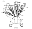
低侵襲性医療処置に用いられるようなロボット制御システムは、比較的小さなツールや器具を正確に制御し且つ駆動するために大規模で複雑な設備を含む。(本明細書で使用する場合に、用語「ロボット」又は「ロボット制御による」等は、遠隔操作又は遠隔ロボット操作の態様を含む。)図1Aは、公知のロボット制御システム100の一例を示す。例えば、Intuitive Surgical, Inc.により市販されているda Vinci(登録商標)手術システムの一部であるシステム100は、複数のアーム130を有する患者側カート110を含む。各アーム130は、器具150を取り付けるとともにこの器具150の操作に機械的な動力を供給するための機械的なインターフェイスを有する駆動システムを一般的に含むようなドッキングポート140を有する。アーム130は、医療処置中に使用され、その処置についてそれぞれ医療器具150を移動させ且つ位置付けすることができる。
Robotic control systems, such as those used in minimally invasive medical procedures, include large and complex equipment to precisely control and drive relatively small tools and instruments. (As used herein, the terms “robot” or “by robot control” and the like include remote control or aspects of remote robot operation.) FIG. 1A illustrates an example of a known
図1Bは、既知の器具150の底面図を示す。器具150は、一般的に、伝達又はバックエンド機構152、バックエンド機構152から延びるメインチューブ154、及びメインチューブ154の先端部に機能チップ156を含む。チップ156は、一般的に、医療処置中に使用されるメス、ハサミ、鉗子、又は焼灼器具等の医療ツールを含む。駆動ケーブルや腱155が、チップ156に接続され、且つメインチューブ154を通ってバックエンド機構152に延びる。バックエンド機構152は、典型的には、器具150の駆動用腱155と駆動システム140の機械的なインターフェイスの電動軸との間に機械的な結合部を提供する。具体的には、ギヤやディスク153は、駆動システム140の機械的なインターフェイス上で相補的な機構に係合するように位置付けされ、サイズ決めされ、且つ成形された突起部や孔等の機構を有する。典型的な器具では、ディスク153の回転によって、それぞれの腱155を引っ張り、且つチップ156内の対応する機械的リンクを作動させる。こうして、システム100は、必要に応じて駆動用腱155の運動及び張力を制御して、チップ156を位置付け、向き合わせ、及び操作することができる。既知の手術システムの更なる詳細は、例えば、(2001年8月13日に出願された、Tierneyらの”Surgical Robotic Tools, Data Architecture, and Use”という標題の)特許文献1に記載されており、この文献は、その全体を参照することにより本明細書に組み込まれる。
FIG. 1B shows a bottom view of
システム100の器具150は、駆動システム140から1つの器具150を取り外し、その後取り外した器具の代わりに他の器具150を設置することにより、交換することができる。一般的に、設置作業は、ディスク153上の機構を駆動システム140の相補的な機構に正確に係合することを必要とする。しかしながら、設置前に、器具150上のディスク153の向きは、一般的に、患者側カート110に伝わっていない。
The
また、患者側カート110等の設備は、大抵の場合、次の医療処置までに複雑な装置をクリーニングし且つ滅菌するのが困難なため、滅菌バリア(例えば、プラスチックシートのドレープ)によって医療処置のために覆われている。この滅菌バリアには、ドッキングポート140と器具のバックエンド152との間に介在する滅菌アダプタが含まれる。例えば、いくつかの例示的な滅菌バリア及びアダプタシステムについて記載する(2006年3月31日に出願された、Andersonらの”Sterile Surgical Adapter”という標題の)特許文献2及び特許文献3を参照されたい。またこれらの文献は、その全体を参照することにより本明細書に組み込まれる。
Also, equipment such as the patient-
器具150の典型的な設置作業は、駆動システム140でのディスク153の向きに関係なく、恐らく介在滅菌アダプタを用いて、バックエンド機構152を取り付けるステップを含む。駆動システム140内の駆動モータは、次に、設置手順の間に複数回前後に回転され、相補的な機構が新しく設置される器具150とかみ合い、この新しく設置された器具150の操作について互いに確実に係合するのを保証する。設置作業中のある時点で、駆動モータは、それぞれのディスク153を回転させるために確実に係合される。
A typical installation operation of the
しかしながら、設置される器具150は、駆動モータが、異なる及び予測不可能なタイミングで器具150のそれぞれのディスク153に積極的に係合するので、設置手順の間に時には予測不可能な態様で移動し得る。特定の用途では、このような予測不可能な動きは、許容できない。一般的には、遮るもののない(clear)又は囲まれたスペースが、設置手順の間に器具チップのランダムな動きに対応するために、器具150の周りに必要とされる。
However, the installed
手術システムは、手術用器具を含み、この手術用器具は、制御されたトルク及び位置を手術用器具に伝達させるのに不利な影響を与えるバックラッシュに敏感である。手術用器具は、機械的なインターフェイスを介して手術用器具マニピュレータアセンブリ内のモータに結合される。機械的なインターフェイスと手術用器具マニピュレータアセンブリとの組合せは、例えば0.7度未満の低バックラッシュを有する。機械的なインターフェイスによって、手術用器具マニピュレータアセンブリ内の駆動インターフェイスを手術用器具の被駆動インターフェイスに結合する。機械的なインターフェイスは、一態様では、外科処置で使用されるトルクレベルについてゼロバックラッシュを有する。 The surgical system includes a surgical instrument that is sensitive to backlash, which adversely affects the transmission of controlled torque and position to the surgical instrument. The surgical instrument is coupled to a motor in the surgical instrument manipulator assembly via a mechanical interface. The combination of mechanical interface and surgical instrument manipulator assembly has a low backlash, eg, less than 0.7 degrees. A mechanical interface couples the drive interface within the surgical instrument manipulator assembly to the driven interface of the surgical instrument. The mechanical interface, in one aspect, has zero backlash for the torque levels used in the surgical procedure.
このように、機器は、手術用器具マニピュレータアセンブリを含む。手術用器具マニピュレータアセンブリは、駆動ユニット及び駆動出力アセンブリを含む。駆動出力アセンブリは、駆動ユニットに結合される。駆動出力アセンブリは、駆動ユニットに結合した低バックラッシュ・カプラを含む。駆動出力ディスクが、低バックラッシュ・カプラに結合される。手術用器具マニピュレータアセンブリのバックラッシュが生じる部分は、駆動ユニット及び駆動出力ディスクを低バックラッシュ・カプラに結合する部分である。 As such, the instrument includes a surgical instrument manipulator assembly. The surgical instrument manipulator assembly includes a drive unit and a drive output assembly. The drive output assembly is coupled to the drive unit. The drive output assembly includes a low backlash coupler coupled to the drive unit. The drive output disk is coupled to the low backlash coupler. The backlash-occurring portion of the surgical instrument manipulator assembly is the portion that couples the drive unit and drive output disk to the low backlash coupler.
一態様では、駆動出力ディスクは、先端面を有する円筒形状本体である。第1の位置合せ要素が、先端面から延びる。第2の位置合せ要素も、先端面から延びる。第1の位置合せ要素は、第2の位置合せ要素から分離される。第1及び第2の位置合せ要素の組合せは、駆動出力ディスク及び別のアセンブリのディスクがかみ合うときに、機器内の別のアセンブリのディスクに対して駆動出力ディスクを向き合わせする。一態様では、第1の位置合せ要素はピンであり、第2の位置合せ要素はタブである。 In one aspect, the drive output disc is a cylindrical body having a tip surface. A first alignment element extends from the tip surface. The second alignment element also extends from the tip surface. The first alignment element is separate from the second alignment element. The combination of the first and second alignment elements orients the drive output disc against the disc of the other assembly in the instrument as the drive output disc and the disc of the other assembly engage. In one aspect, the first alignment element is a pin and the second alignment element is a tab.
この態様では、駆動出力ディスクの先端面は、中心部及び周縁部を有する。複数の駆動ドッグが、先端面から延びる。各駆動ドッグは、中心部から第1の距離に位置付けされた第1エッジ面と、周端部の周りに隣接して位置付けされた第2エッジ面とを含む。第2エッジ面は、第1エッジ面の反対側にある。また、各駆動ドッグは、先端面から延びる3次元矩形構造等の3次元構造である第1部分と、第1部分から延びる第2部分とを含む。第2部分は、第2部分の2つの対向する側面を有する。第2部分の側面のそれぞれは、湾曲面である。一態様では、湾曲面は、円形断面の一部、例えば円筒体の外面の一部である。 In this aspect, the front end surface of the drive output disk has a central portion and a peripheral portion. A plurality of drive dogs extend from the tip surface. Each drive dog includes a first edge surface located at a first distance from the center and a second edge surface adjacently positioned around the peripheral edge. The second edge surface is on the opposite side of the first edge surface. Further, each drive dog includes a first portion that is a three-dimensional structure such as a three-dimensional rectangular structure that extends from the tip end surface, and a second portion that extends from the first portion. The second portion has two opposite sides of the second portion. Each of the side surfaces of the second portion is a curved surface. In one aspect, the curved surface is part of a circular cross section, for example part of the outer surface of a cylinder.
駆動出力アセンブリは、シャフトも含む。第1の予圧ばねが、シャフトに結合される。第1の予圧ばねは、駆動出力ディスクにも結合される。第1の予圧ばねは、第1の予圧ばねが圧縮されたときに、第1の予圧力を駆動出力ディスクに加えるように構成される。 The drive output assembly also includes a shaft. A first preload spring is coupled to the shaft. The first preload spring is also coupled to the drive output disk. The first preload spring is configured to apply a first preload to the drive output disc when the first preload spring is compressed.
駆動出力アセンブリは、シャフトに結合した第2の予圧ばねも含む。第1の予圧ばねと組み合わせた第2の予圧ばねは、第1及び第2の予圧ばねが圧縮されたときに、第2の予圧力を駆動出力ディスクに加えるように構成される。第2の予圧力は、第1の予圧力よりも大きい。 The drive output assembly also includes a second preload spring coupled to the shaft. A second preload spring in combination with the first preload spring is configured to apply a second preload to the drive output disc when the first and second preload springs are compressed. The second preload is greater than the first preload.
手術用器具マニピュレータアセンブリは、複数の駆動ユニットを含むモータパックを有する。複数の駆動ユニットは、前述した駆動ユニットを含む。モータパックは、手術用器具マニピュレータアセンブリのハウジングに移動可能に取り付けられる。モータパックは、複数のハードストップ(hard stop)も含む。複数のハードストップは、モータパックの先端面から延びるように構成される。 The surgical instrument manipulator assembly has a motor pack that includes a plurality of drive units. The plurality of drive units includes the drive unit described above. The motor pack is movably attached to the housing of the surgical instrument manipulator assembly. The motor pack also includes a plurality of hard stops. The plurality of hard stops are configured to extend from the tip surface of the motor pack.
手術用器具マニピュレータアセンブリは、解除ラッチも含む。解除ラッチは、手術用器具マニピュレータアセンブリのハウジングに旋回可能に取り付けられる。ピンが、解除ラッチの基端部からハウジングの内部に延びる。一態様では、ピンは、ばねで付勢されるピンである。 The surgical instrument manipulator assembly also includes a release latch. The release latch is pivotally attached to the housing of the surgical instrument manipulator assembly. A pin extends inside the housing from the proximal end of the release latch. In one aspect, the pin is a spring biased pin.
手術用器具マニピュレータアセンブリのモータパックは、解除ラッチを阻止する解除ラッチ阻止ストップも含む。一態様では、モータパックが、手術用器具マニピュレータアセンブリのハウジングに対して完全な引込み位置にある場合に、解除ラッチの操作は、阻止されない。しかしながら、モータパックがこのハウジングに対して第1の位置にある場合に、ピンが解除ラッチ阻止ストップに接触し、解除ラッチが押された場合に、解除ラッチの旋回を防止する。別の態様では、解除ラッチ阻止ストップは、モータパックが完全な引込み位置にあるときに、手術用器具が滅菌アダプタアセンブリに取り付けられる間、解除ラッチの旋回を防止する。 The motor pack of the surgical instrument manipulator assembly also includes a release latch blocking stop that blocks the release latch. In one aspect, operation of the release latch is not blocked when the motor pack is in the fully retracted position with respect to the housing of the surgical instrument manipulator assembly. However, when the motor pack is in the first position relative to this housing, the pin contacts the release latch blocking stop and prevents pivoting of the release latch when the release latch is pushed. In another aspect, the release latch detent stop prevents pivoting of the release latch while the surgical instrument is attached to the sterile adapter assembly when the motor pack is in the fully retracted position.
別の態様では、機器は、手術用装置アセンブリ、予圧トラック、及び予圧トラックに乗った予圧アセンブリを含む。予圧アセンブリは、手術用装置アセンブリに結合される。挿入アセンブリが、予圧トラックを含む。 In another aspect, the instrument includes a surgical device assembly, a preload track, and a preload assembly mounted on the preload track. The preload assembly is coupled to the surgical device assembly. The insert assembly includes a preload track.
予圧アセンブリが、予圧トラック上の第1の位置に位置付けされるときに、予圧アセンブリは、第1の力を手術用装置アセンブリに加える。予圧アセンブリが、予圧トラック上の第2位置に位置付けされるときに、予圧アセンブリは、第2の力を手術用装置アセンブリに加える。第2の力は、第1の力よりも大きい。 The preload assembly applies a first force to the surgical device assembly when the preload assembly is positioned in a first position on the preload track. The preload assembly exerts a second force on the surgical device assembly when the preload assembly is positioned in the second position on the preload track. The second force is greater than the first force.
一態様では、予圧アセンブリは、カム従動アセンブリ及びアームを含む。カム従動アセンブリは、予圧トラック上に乗っている。アームは、第1端部及び第2端部を有する。第1端部は、手術用装置アセンブリに結合される。アームの第2端部は、カム従動アセンブリに結合される。カム従動アセンブリが予圧トラック上の第1の位置に位置付けされる場合に、アームは、第1の力に比例した力をカム従動アセンブリから手術用装置アセンブリに伝達するように構成される。カム従動アセンブリが予圧トラック上の第2の位置に位置付けされる場合に、アームは、第2の力に比例した力をカム従動アセンブリから手術用装置アセンブリに伝達するように構成される。 In one aspect, the preload assembly includes a cam follower assembly and an arm. The cam follower assembly rides on a preload track. The arm has a first end and a second end. The first end is coupled to the surgical device assembly. The second end of the arm is coupled to the cam follower assembly. The arm is configured to transfer a force proportional to the first force from the cam follower assembly to the surgical device assembly when the cam follower assembly is positioned in the first position on the preload track. The arm is configured to transfer a force proportional to the second force from the cam follower assembly to the surgical device assembly when the cam follower assembly is positioned in the second position on the preload track.
手術用装置アセンブリは、駆動ユニット・ハウジング及びモータパックも含む。モータパックは、駆動ユニット・ハウジングに移動可能に取り付けられる。アームの第1端部は、モータパックに結合される。カム従動アセンブリが予圧トラック上の第1の位置に位置付けされる場合に、アームは、第1の力に比例した力をカム従動アセンブリからモータパックに伝達するように構成される。カム従動アセンブリが予圧トラック上の第2の位置に位置付けされる場合に、アームは、第2の力に比例した力をカム従動アセンブリからモータパックに伝達するように構成される。 The surgical device assembly also includes a drive unit housing and a motor pack. The motor pack is movably mounted in the drive unit housing. The first end of the arm is coupled to the motor pack. The arm is configured to transfer a force from the cam follower assembly to the motor pack when the cam follower assembly is positioned in a first position on the preload track. The arm is configured to transfer a force proportional to the second force from the cam follower assembly to the motor pack when the cam follower assembly is positioned in the second position on the preload track.
別の態様では、機器は、予圧トラックと、この予圧トラック上に乗るように構成された予圧アセンブリとを含む。予圧アセンブリは、手術用装置アセンブリに結合するように構成される。予圧アセンブリは、予圧アセンブリが予圧トラック上の第1の位置に位置付けされる場合に、第1の力を手術用装置アセンブリに加えるように構成される。 In another aspect, the apparatus includes a preload track and a preload assembly configured to ride on the preload track. The preload assembly is configured to couple to the surgical device assembly. The preload assembly is configured to apply a first force to the surgical device assembly when the preload assembly is positioned in the first position on the preload track.
予圧アセンブリは、予圧リセット機構を含む。予圧リセット機構は、予圧アセンブリを予圧トラック上の第1の位置に自動的に位置決めするように構成される。 The preload assembly includes a preload reset mechanism. The preload reset mechanism is configured to automatically position the preload assembly in a first position on the preload track.
さらに別の態様では、機器は、手術用器具マニピュレータアセンブリ、挿入アセンブリ、及び予圧アセンブリを含む。手術用器具マニピュレータアセンブリは、ハウジング及びモータパックを含む。モータパックは、ハウジングに移動可能に取り付けられる。挿入アセンブリは、手術用器具マニピュレータアセンブリに結合される。挿入アセンブリは、予圧トラックも含む。予圧アセンブリは、カム被駆動アセンブリ、アーム、及び予圧リセットアセンブリを含む。アームは、第1端部及び第2端部を含む。アームの第1端部は、カム従動アセンブリに回転可能に接続される。アームの第2端部は、モータパックに結合される。カム従動アセンブリは、予圧トラック上に乗るように構成される。予圧リセットアセンブリは、予圧アセンブリを予圧トラック上の第1の位置に自動的に位置付けするように構成される。第1の位置では、予圧アセンブリは、第1の力をモータパックに加える。 In yet another aspect, the instrument includes a surgical instrument manipulator assembly, an insertion assembly, and a preload assembly. The surgical instrument manipulator assembly includes a housing and a motor pack. The motor pack is movably attached to the housing. The insertion assembly is coupled to the surgical instrument manipulator assembly. The insert assembly also includes a preload track. The preload assembly includes a cam driven assembly, an arm, and a preload reset assembly. The arm includes a first end and a second end. The first end of the arm is rotatably connected to the cam follower assembly. The second end of the arm is coupled to the motor pack. The cam follower assembly is configured to ride on the preload track. The preload reset assembly is configured to automatically position the preload assembly in a first position on the preload track. In the first position, the preload assembly applies a first force to the motor pack.
別の機器は、挿入アセンブリ、器具マニピュレータアセンブリ、手術用装置インターフェイス、及び手術用器具を含む。時には、手術用装置インターフェイスは、手術用装置インターフェイス要素とも呼称される。挿入アセンブリは、先端部及び予圧トラックを含む。器具マニピュレータアセンブリは、挿入アセンブリの先端部に結合される。器具マニピュレータアセンブリは、駆動出力ディスクを含む。駆動出力ディスクは、駆動出力インターフェイスを有する。 Other instruments include insertion assemblies, instrument manipulator assemblies, surgical device interfaces, and surgical instruments. Sometimes the surgical device interface is also referred to as the surgical device interface element. The insert assembly includes a tip and a preload track. The instrument manipulator assembly is coupled to the tip of the insertion assembly. The instrument manipulator assembly includes a drive output disc. The drive output disk has a drive output interface.
手術用装置インターフェイスは、器具マニピュレータアセンブリに取り付けられる。手術用装置インターフェイスは、中間ディスクを含む。中間ディスクは、被駆動中間インターフェイス及び駆動中間インターフェイスを有する。被駆動中間インターフェイスは、駆動出力インターフェイスに結合される。 The surgical device interface is attached to the instrument manipulator assembly. The surgical device interface includes an intermediate disc. The intermediate disc has a driven intermediate interface and a driving intermediate interface. The driven intermediate interface is coupled to the drive output interface.
手術用器具は、手術用装置インターフェイスに取り付けられる。手術用器具は、被駆動ディスクを含む。被駆動ディスクは、被駆動インターフェイスを含む。被駆動インターフェイスは、駆動中間インターフェイスに結合される。 The surgical instrument is attached to the surgical device interface. The surgical instrument includes a driven disc. The driven disk includes a driven interface. The driven interface is coupled to the driving intermediate interface.
第1の力が駆動出力ディスクと中間ディスクとの間の結合部に加えられる場合に、駆動出力ディスクと中間ディスクとの間の結合部は、2つのディスクを位置合わせするために使用されるトルクレベルについて非ゼロバックラッシを有する。第2の力が駆動出力ディスクと中間ディスクとの間の結合部に加えられる場合に、駆動出力ディスクと中間ディスクとの間の結合部は、外科処置で使用されるトルクレベルについてゼロバックラッシュを有する。第2の力は、第1の力よりも大きい。 The joint between the drive output disc and the intermediate disc is a torque used to align the two discs when a first force is applied to the joint between the drive output disc and the intermediate disc. Has a non-zero backlash for the level. When a second force is applied to the joint between the drive output disc and the intermediate disc, the joint between the drive output disc and the intermediate disc provides zero backlash for the torque levels used in the surgical procedure. Have. The second force is greater than the first force.
このように、機器は、駆動出力ディスク及び中間ディスクを含む。駆動出力ディスクは、先端面と、この先端面から延びる複数の駆動ドッグとを含む。複数の駆動ドッグの各駆動ドッグは、先端面から延びる例えば3次元矩形構造等の3次元構造である第1部分と、第1部分から延びる第2部分とを含む。第2部分は、第2部分の2つの対向する側面を含む。第2部分の側面のそれぞれは、湾曲面である。一態様では、湾曲面は、円形断面の一部、例えば円筒体の外面の一部である。中間ディスクは、基端面と、この基端面から中間ディスク内に延びる複数の駆動ドッグ用レセプタクルとを含む。複数の駆動ドッグ用レセプタクルの各駆動ドッグ用レセプタクルは、複数の駆動ドッグのうちの1つを受容するように構成される。複数の駆動ドッグ用レセプタクルの各駆動ドッグ用レセプタクルは、外面から中間ディスク内に延びる対向する側壁を含む第1部分と、駆動ドッグ用レセプタクルの底面である第2部分と、第1部分から第2部分に延びる第3部分とを含む。第3部分は、第3部分の2つの対向する傾斜した側面を有する。 Thus, the instrument includes a drive output disc and an intermediate disc. The drive output disk includes a tip surface and a plurality of drive dogs extending from the tip surface. Each drive dog of the plurality of drive dogs includes a first portion that is a three-dimensional structure, such as a three-dimensional rectangular structure, that extends from the tip surface, and a second portion that extends from the first portion. The second portion includes two opposite sides of the second portion. Each of the side surfaces of the second portion is a curved surface. In one aspect, the curved surface is part of a circular cross section, for example part of the outer surface of a cylinder. The intermediate disc includes a proximal end face and a plurality of drive dog receptacles extending from the proximal end face into the intermediate disc. Each drive dog receptacle of the plurality of drive dog receptacles is configured to receive one of the plurality of drive dogs. Each drive dog receptacle of the plurality of drive dog receptacles includes a first portion including opposing side walls extending from an outer surface into the intermediate disc, a second portion that is a bottom surface of the drive dog receptacle, and first to second portions. A third portion extending to the portion. The third portion has two opposite sloped sides of the third portion.
機器は、駆動出力ディスクに結合した第1の予圧ばねを有する。第1の予圧ばねは、駆動出力ディスクが中間ディスクに結合したときに、圧縮される。第1の予圧ばねの圧縮によって、予圧力が駆動出力ディスクに加えられる。予圧力を駆動出力ディスクに加えるときに、駆動出力ディスクと中間ディスクとの間の結合部は、ディスクを位置合わせするのに必要なトルクレベルについて非ゼロバックラッシュを有する。 The instrument has a first preload spring coupled to the drive output disc. The first preload spring is compressed when the drive output disc is coupled to the intermediate disc. The compression of the first preload spring applies a preload to the drive output disc. When applying a preload to the drive output disc, the connection between the drive output disc and the intermediate disc has a non-zero backlash for the torque level required to align the disc.
機器は、駆動出力ディスクに結合した第2の予圧ばねも含む。予圧アセンブリは、第1及び第2の予圧ばねに結合される。予圧アセンブリが第1及び第2の予圧ばねを圧縮するときに、圧縮された第1ばねと組み合される圧縮された第2ばねは、第2の予圧力を駆動出力ディスクと中間ディスクとの間の結合部に加える。第2の予圧力を結合部に加えるときに、駆動出力ディスクと中間ディスクとの間の結合部は、外科処置で使用されるトルクレベルについてゼロバックラッシュを有する。 The instrument also includes a second preload spring coupled to the drive output disc. The preload assembly is coupled to the first and second preload springs. A second compressed spring is combined with the first compressed spring when the preload assembly compresses the first and second preload springs to provide a second preload between the drive output disc and the intermediate disc. Add to the joint. When applying the second preload to the joint, the joint between the drive output disc and the intermediate disc has zero backlash for the torque level used in the surgical procedure.
さらに別の態様では、機器は、手術用装置インターフェイス要素を含む。手術用装置インターフェイス要素は、複数の中間ディスクと、その内部に回転可能に取り付けられた複数の中間ディスクを有する第1の本体構造とを含む。 In yet another aspect, the instrument includes a surgical device interface element. The surgical device interface element includes a plurality of intermediate discs and a first body structure having a plurality of intermediate discs rotatably mounted therein.
各中間ディスクは、被駆動中間インターフェイス及び駆動中間インターフェイスを含む。駆動中間インターフェイスは、被駆動中間インターフェイスとは反対側にある。 Each intermediate disc includes a driven intermediate interface and a driven intermediate interface. The driving intermediate interface is on the opposite side of the driven intermediate interface.
被駆動中間インターフェイスは、第1の位置合せレセプタクル及び駆動ドッグ用レセプタクルを含む。駆動中間インターフェイスは、駆動ドッグ及び係合構造を含む。 The driven intermediate interface includes a first alignment receptacle and a drive dog receptacle. The drive intermediate interface includes a drive dog and an engagement structure.
第1の位置合せレセプタクルは、手術用器具マニピュレータアセンブリの駆動出力ディスクから延びる第1の位置合せ要素とかみ合うように構成される。被駆動中間インターフェイスは、第2の位置合せレセプタクルも含む。第2の位置合せレセプタクルは、駆動出力ディスクから延びる第2の位置合せ要素とかみ合うように構成される。第1の位置合せレセプタクルは、第2の位置合せレセプタクルから分離される。第1及び第2の位置合せレセプタクルの組合せは、駆動出力ディスク及び中間ディスクが結合する、例えばかみ合うときに、駆動出力ディスクを中間ディスクに向き合わせする。 The first alignment receptacle is configured to mate with a first alignment element extending from the drive output disc of the surgical instrument manipulator assembly. The driven intermediate interface also includes a second alignment receptacle. The second alignment receptacle is configured to mate with a second alignment element extending from the drive output disc. The first alignment receptacle is separate from the second alignment receptacle. The combination of the first and second alignment receptacles orients the drive output disc and the intermediate disc when the drive output disc and the intermediate disc are mated, eg, mated.
第1の本体構造は、複数のハードストップを含む。各中間ディスクは、ハードストップのうちの1つに関連付けられる。各中間ディスクは、その中間ディスクの外側面から延びるハードストップ・タブを有する。中間ディスクの第1の軸線方向位置では、ハードストップ・タブは、中間ディスクを回転させたときに、中間ディスクに関連付けられたハードストップに接触する。中間ディスクの第2の軸線方向位置では、中間ディスクは、中間ディスクに関連付けられたハードストップに接触するハードストップ・タブを用いることなく、自由に回転する。 The first body structure includes a plurality of hard stops. Each intermediate disc is associated with one of the hard stops. Each intermediate disc has a hard stop tab extending from the outer surface of the intermediate disc. In the first axial position of the intermediate disc, the hard stop tab contacts the hard stop associated with the intermediate disc when the intermediate disc is rotated. In the second axial position of the intermediate disc, the intermediate disc is free to rotate without the hard stop tabs contacting the hard stops associated with the intermediate disc.
駆動ドッグ用レセプタクルのそれぞれは、中間ディスクの外面から中間ディスク内に延びる対向した側壁を有する第1部分を含む。駆動ドッグ用レセプタクルの第2部分は、駆動ドッグ用レセプタクルの底面である。駆動ドッグ用レセプタクルの第3部分は、第1部分から第2部分に延びる。第3部分は、第3部分の2つの対向する側面を含む。第3部分の側面のそれぞれは、傾斜面である。一態様では、この傾斜面は、楔形状の側面の一部である。 Each of the drive dog receptacles includes a first portion having opposed sidewalls extending from the outer surface of the intermediate disc into the intermediate disc. The second portion of the drive dog receptacle is the bottom surface of the drive dog receptacle. The third portion of the drive dog receptacle extends from the first portion to the second portion. The third portion includes two opposite sides of the third portion. Each of the side surfaces of the third portion is an inclined surface. In one aspect, the sloped surface is part of a wedge-shaped side surface.
中間ディスクの駆動ドッグのそれぞれは、3次元構造体、例えば3次元矩形構造である第1部分を有する。駆動ドッグの第2部分は、第1部分から延びる。第2部分は、第2部分の2つの対向する側面を有する。第2部分の側面のそれぞれは、湾曲面の一部である。一態様では、湾曲面は、円形断面の一部、例えば円筒体の外面の一部である。 Each drive dog of the intermediate disc has a first part which is a three-dimensional structure, for example a three-dimensional rectangular structure. The second portion of the drive dog extends from the first portion. The second portion has two opposite sides of the second portion. Each of the side surfaces of the second portion is a part of a curved surface. In one aspect, the curved surface is part of a circular cross section, for example part of the outer surface of a cylinder.
中間ディスクの駆動ドッグ用レセプタクルのそれぞれは、駆動ドッグ用レセプタクルのそれぞれが第1平面によって二等分されるように、位置付けされる。中間ディスクの駆動ドッグのそれぞれは、駆動ドッグのそれぞれが第2平面によって二等分されるように、位置付けされる。第1平面は、第2平面に直交する。 Each of the drive dog receptacles of the intermediate disc is positioned such that each of the drive dog receptacles is bisected by the first plane. Each drive dog of the intermediate disc is positioned such that each drive dog is bisected by the second plane. The first plane is orthogonal to the second plane.
手術用装置インターフェイス要素は、第2の本体構造も含む。第1の本体構造は、第2の本体構造に移動可能に取り付けられる。第2の本体構造は、スキッドプレートを含む。 The surgical device interface element also includes a second body structure. The first body structure is movably attached to the second body structure. The second body structure includes a skid plate.
中間ディスクは、先端面も含む。一態様では、係合構造は、先端面から先端方向に延びる開放3次元構造である。開放3次元構造は、略C字形状の構造である。C字形状構造は、高さ、第1端部、及び第2端部を含む。第1及び第2端部は、C字形状構造体の開口部の境界を区切る。中心線が、C字形状構造の中心を通って延びる。中心線は、第1及び第2端部から等距離にある。 The intermediate disc also includes a tip surface. In one aspect, the engagement structure is an open three-dimensional structure extending in the distal direction from the distal end surface. The open three-dimensional structure is a substantially C-shaped structure. The C-shaped structure includes a height, a first end, and a second end. The first and second ends delimit the boundaries of the opening of the C-shaped structure. A centerline extends through the center of the C-shaped structure. The centerline is equidistant from the first and second ends.
開放3次元構造は、第1及び第2端部の一方から延びる壁も含む。この壁は、C字形状構造体の中心線に対して略平行な方向に延びる。壁は、中間ディスクの先端面の外縁に向けても延びる。壁は、C字形状構造体の高さ未満の高さを有する。 The open three dimensional structure also includes a wall extending from one of the first and second ends. The wall extends in a direction substantially parallel to the centerline of the C-shaped structure. The wall also extends towards the outer edge of the tip surface of the intermediate disc. The wall has a height less than the height of the C-shaped structure.
別の態様では、開放3次元構造は、円形トラックである。円形トラックは、第1の高さ、第1端部、及び第2端部を有する第1の周囲部分を含む。円形トラックは、第1の周囲部分の第1端部と第2端部との間に延びる第2の周囲部分も含む。第2の周囲部分は、第2の高さを有する。第2の高さは、第1の高さ未満である。円形トラックの中心線が、円形トラックの中心を通って延びており、且つ第1及び第2端部から等距離にある。C字形状構造は、円形トラックの一例である。この態様では、開放3次元構造は、第1の周囲部分の第1及び第2端部の一方から円形断面の中心線に対して略平行な方向に延びる壁も含む。この壁は、複数の中間ディスクのうちの中間ディスクの先端面の外縁に向けて延びる。この壁は、高さを有する。壁の高さは、第1の周囲部分の第1の高さ未満である。 In another aspect, the open three dimensional structure is a circular track. The circular track includes a first peripheral portion having a first height, a first end and a second end. The circular track also includes a second peripheral portion extending between the first end and the second end of the first peripheral portion. The second peripheral portion has a second height. The second height is less than the first height. A centerline of the circular track extends through the center of the circular track and is equidistant from the first and second ends. The C-shaped structure is an example of a circular track. In this aspect, the open three dimensional structure also includes a wall extending from one of the first and second ends of the first peripheral portion in a direction generally parallel to the centerline of the circular cross section. The wall extends toward the outer edge of the tip surface of the intermediate disc among the plurality of intermediate discs. This wall has a height. The height of the wall is less than the first height of the first peripheral portion.
一態様では、手術用装置インターフェイス要素は、手術用器具マニピュレータアセンブリに取り付けられる。手術用器具マニピュレータアセンブリは、駆動インターフェイスを有する駆動出力ディスクを含む。駆動インターフェイスは、中間ディスクの被駆動中間インターフェイスに結合される。所定の予圧力を駆動出力ディスクに加える際に、中間ディスクと駆動出力ディスクとの間の結合部は、外科処置で使用されるトルクレベルについてゼロバックラッシュを有する。 In one aspect, the surgical device interface element is attached to a surgical instrument manipulator assembly. The surgical instrument manipulator assembly includes a drive output disk having a drive interface. The drive interface is coupled to the driven intermediate interface of the intermediate disc. Upon applying a predetermined preload to the drive output disc, the connection between the intermediate disc and the drive output disc has zero backlash for the torque levels used in the surgical procedure.
別の態様では、手術用器具は、手術用装置インターフェイス要素に取り付けられる。手術用器具は、被駆動インターフェイスを含む被駆動ディスクをさらに有する。被駆動インターフェイスは、中間ディスクの駆動中間インターフェイスに結合される。所定の予圧力を中間ディスクに加える際に、中間ディスクと被駆動ディスクとの間の結合部は、外科処置で使用されるトルクレベルについてゼロバックラッシュを有する。 In another aspect, the surgical instrument is attached to the surgical device interface element. The surgical instrument further has a driven disk that includes a driven interface. The driven interface is coupled to the driving intermediate interface of the intermediate disc. Upon applying a predetermined preload to the intermediate disc, the connection between the intermediate disc and the driven disc has zero backlash for the torque levels used in the surgical procedure.
こうして、一態様では、機器は、中間ディスク及び被駆動ディスクを含む。中間ディスクは、被駆動中間インターフェイス及び駆動中間インターフェイスを含む。駆動中間インターフェイスは、被駆動中間インターフェイスとは反対側にある。 Thus, in one aspect, the device includes an intermediate disc and a driven disc. The intermediate disc includes a driven intermediate interface and a driving intermediate interface. The driving intermediate interface is on the opposite side of the driven intermediate interface.
被駆動中間インターフェイスは、位置合せレセプタクル及び駆動ドッグ用レセプタクルを含む。被駆動中間インターフェイスは、駆動ドッグ及び係合構造を含む。 The driven intermediate interface includes an alignment receptacle and a drive dog receptacle. The driven intermediate interface includes a drive dog and an engagement structure.
被駆動ディスクは、駆動中間インターフェイスとかみ合うように構成された被駆動インターフェイスを含む。被駆動インターフェイスは、係合レセプタクル、駆動ドッグ用レセプタクル、及び回転禁止要素を含む。回転禁止要素は、被駆動ディスクの回転を防止する回転ロック機構を含む。係合レセプタクルは、係合構造が係合レセプタクルと位置合わせされる場合に、係合構造を受容するように構成される。 The driven disc includes a driven interface configured to mate with a drive intermediate interface. The driven interface includes an engagement receptacle, a drive dog receptacle, and a rotation inhibiting element. The rotation inhibiting element includes a rotation lock mechanism that prevents rotation of the driven disk. The engagement receptacle is configured to receive the engagement structure when the engagement structure is aligned with the engagement receptacle.
さらに別の態様では、機器は、手術用器具を含む。手術用器具は、被駆動ディスク用レセプタクルを有する本体を含む。手術用器具内にあるシャフトの基端部は、被駆動ディスク用レセプタクル内に延びる。被駆動ディスクは、被駆動ディスクが被駆動ディスク用レセプタクルに位置付けされるように、シャフトの基端部に取り付けられる。 In yet another aspect, the device comprises a surgical instrument. The surgical instrument includes a body having a driven disk receptacle. The proximal end of the shaft within the surgical instrument extends into the driven disk receptacle. The driven disc is attached to the proximal end of the shaft such that the driven disc is positioned in the driven disc receptacle.
被駆動ディスクは、被駆動インターフェイスを含む。被駆動インターフェイスは、係合レセプタクル、駆動ドッグ用レセプタクル、及び回転禁止要素を含む。回転禁止要素は、回転ロック機構を有する。回転禁止要素の係合の際に、回転ロック機構は、被駆動ディスク用レセプタクルに係合し、被駆動ディスクの回転を防止する。 The driven disk includes a driven interface. The driven interface includes an engagement receptacle, a drive dog receptacle, and a rotation inhibiting element. The rotation inhibiting element has a rotation lock mechanism. When the rotation inhibiting element is engaged, the rotation lock mechanism engages with the driven disk receptacle to prevent rotation of the driven disk.
駆動ドッグ用レセプタクルのそれぞれは、第1部分、第2部分、及び第3部分を含む。第1部分は、被駆動ディスクの基端面から被駆動ディスク内に延びる対向した側壁を含む。第2部分は、駆動ドッグ用レセプタクルの底面である。第3部分は、第1部分から第2部分に延びる。第3部分は、第3部分の2つの対向する側面を有する。第3部分の側面のそれぞれは、傾斜面を含む。一態様では、傾斜面は、楔形状の側面の一部である。一態様では、各駆動ドッグ用レセプタクルは、被駆動ディスクの縦軸から第1の距離に位置付けされた第1エッジ面と、第1エッジ面の反対側の開放した第2エッジ面とを含む。 Each of the drive dog receptacles includes a first portion, a second portion, and a third portion. The first portion includes opposed side walls extending into the driven disk from the proximal end surface of the driven disk. The second part is the bottom surface of the drive dog receptacle. The third portion extends from the first portion to the second portion. The third portion has two opposite sides of the third portion. Each of the side surfaces of the third portion includes an inclined surface. In one aspect, the sloped surface is part of a wedge-shaped side surface. In one aspect, each drive dog receptacle includes a first edge surface positioned at a first distance from a longitudinal axis of the driven disk and an open second edge surface opposite the first edge surface.
係合レセプタクルは、被駆動ディスクの基端面から被駆動ディスク内に延びる溝を含む。溝は、第1端部から第2端部に延びる。溝は、幅及び深さを有する。溝の第1端部は、第1ギャップによって回転禁止要素から分離される。溝の第2端部は、第2ギャップによって回転禁止要素から分離される。溝の幅及び深さは、駆動中間インターフェイスの係合構造を中間ディスク上で受容するようにサイズ決めされる。 The engagement receptacle includes a groove extending from the base end surface of the driven disk into the driven disk. The groove extends from the first end to the second end. The groove has a width and a depth. The first end of the groove is separated from the anti-rotation element by the first gap. The second end of the groove is separated from the anti-rotation element by the second gap. The width and depth of the groove are sized to receive the engagement structure of the drive intermediate interface on the intermediate disk.
一態様では、回転禁止要素は、屈曲部である。回転ロック機構は、屈曲部から延びる。この態様では、回転ロック機構は、タングを含む。 In one aspect, the rotation inhibiting element is a bend. The rotation lock mechanism extends from the bent portion. In this aspect, the rotation lock mechanism includes a tongue.
被駆動ディスク用レセプタクルは、底面を有する。複数の歯が、底面から基端方向に延びる。 The driven disk receptacle has a bottom surface. A plurality of teeth extend proximally from the bottom surface.
機器は、滅菌アダプタアセンブリも含む。手術用器具は、滅菌アダプタアセンブリに取り付けられる。滅菌アダプタアセンブリは、被駆動ディスクの被駆動インターフェイスに結合した駆動中間インターフェイスを有する中間ディスクを含む。所定の予圧力を中間ディスクに加える際に、中間ディスクと被駆動ディスクとの間の結合部は、ゼロバックラッシュを有する。 The instrument also includes a sterile adapter assembly. The surgical instrument is attached to the sterile adapter assembly. The sterile adapter assembly includes an intermediate disc having a drive intermediate interface coupled to the driven interface of the driven disc. The joint between the intermediate disc and the driven disc has zero backlash when a predetermined preload is applied to the intermediate disc.
機器は、手術用器具マニピュレータアセンブリも含む。滅菌アダプタアセンブリは、手術用器具マニピュレータアセンブリに取り付けられる。手術用器具マニピュレータアセンブリは、中間ディスクの被駆動インターフェイスに結合した駆動インターフェイスを有する駆動出力ディスクを含む。所定の予圧力を駆動出力ディスクに加える際に、中間ディスクと駆動出力ディスクとの間の結合部は、外科処置で使用されるトルクレベルについてゼロバックラッシュを有する。 The instrument also includes a surgical instrument manipulator assembly. The sterile adapter assembly is attached to the surgical instrument manipulator assembly. The surgical instrument manipulator assembly includes a drive output disc having a drive interface coupled to a driven interface of the intermediate disc. Upon applying a predetermined preload to the drive output disc, the connection between the intermediate disc and the drive output disc has zero backlash for the torque levels used in the surgical procedure.
図面では、一桁台の図番について、要素の参照符号の最初の数字は、その要素が最初に現れる図面の番号である。二桁台の図番について、要素の参照符号の最初の2桁の数字は、その要素が最初に現れる図面の番号である。 In the drawings, for single-digit drawing numbers, the first digit of an element's reference number is the drawing number in which the element first appears. For a two-digit drawing number, the first two digits of the element's reference number are the drawing number in which the element first appears.
一態様では、手術システム200(図2参照)、例えば低侵襲性の遠隔操作手術システムは、アーム220を有する患者側カート210を含む。エントリガイド・マニピュレータ230が、アーム220の端部にある。マスター器具マニピュレータ280が、エントリガイド・マニピュレータ230に取り付けられ、次に、そのマスター器具マニピュレータ280は、複数の手術用装置アセンブリを支持する。一態様では、手術用装置アセンブリは、手術用器具マニピュレータアセンブリ240、器具滅菌アダプタアセンブリ250、及び手術用器具260を含む。
In one aspect, the surgical system 200 (see FIG. 2), eg, a minimally invasive teleoperated surgical system, includes a
手術用器具マニピュレータアセンブリ240は、時には、器具マニピュレータアセンブリ240と呼称される。器具滅菌アダプタアセンブリ250は、時には、滅菌アダプタアセンブリ250と呼称される。
Surgical
エントリガイド・マニピュレータ230は、手術用装置アセンブリのピッチ及びヨー運動をグループとして変更する。各手術用器具260のメインチューブは、異なるチャネルを通ってシングルポートのエントリガイド270内に延びる。この態様では、シングルポートのエントリガイド270は、カニューレに取り付けられる。シングルポートは、患者内部の手術部位への単一のアクセス位置(例えば、単一の切開部、単一の自然オリフィス等)を指す。
The
本明細書で使用される場合に、カニューレは、患者の体壁を通過し、且つ患者と直接的に接触するチューブである。カニューレは、一般的に、患者に対して出入りするように摺動しないが、カニューレは、運動の遠隔中心と呼称されるその軸線上の点の周りでピッチ及びヨー運動をすることができる。 As used herein, a cannula is a tube that passes through the body wall of a patient and is in direct contact with the patient. The cannula generally does not slide in and out of the patient, but the cannula is capable of pitch and yaw movements about a point on its axis called the distant center of movement.
本明細書で使用される場合に、シングルポートのエントリガイド270は、全ての手術用器具及びカメラ機器が、患者内部の位置に到達するために通過しなければならないチューブである。エントリガイド270は、それぞれの器具について別々の管腔を有する。エントリガイド270は、カニューレを通過し、且つカニューレに対してねじることができる。
As used herein, the single
本明細書で使用される場合に、バックラッシュは、機械的なインターフェイスの接続部を移動させずに、この機械的なインターフェイスの一部を移動してしまう最大角度である。手術用器具260は、制御したトルク及び位置を器具マニピュレータアセンブリ240から手術用器具260に伝達させるのに不利な影響を与えるようなバックラッシュに敏感である。以下でより完全に説明するように、手術用器具260は、機械的なインターフェイスを介して器具マニピュレータアセンブリ240のモータに結合される。機械的なインターフェイスと器具マニピュレータアセンブリ240との組合せは、例えば0.7度未満の低バックラッシュを有する。一態様では、器具マニピュレータアセンブリ240内の出力ディスク(駆動出力ディスク)から手術用器具260の入力ディスク(被駆動ディスク)までで、機械的なインターフェイスは、ゼロバックラッシュを有する。
Backlash, as used herein, is the maximum angle that moves a portion of a mechanical interface without moving the connections of the mechanical interface.
一態様では、機械的なインターフェイスは、滅菌アダプタアセンブリ250を含む。滅菌アダプタアセンブリ250は、滅菌ドレープ(図示せず)を含む。滅菌ドレープは、当技術分野の精通者に知られている構成と同等の態様で構成される。滅菌アダプタアセンブリ250は、使い捨て製品である。従って、滅菌アダプタアセンブリ250に実装された機械的なインターフェイスの部分は、以下でより完全に説明するように、最小の部品点数を含む。
In one aspect, the mechanical interface includes a
手術用器具260の伝達ユニットが、複数の並列入力シャフトを有する。製造のばらつきや公差によって、これらの入力シャフトの全てが、完全に平行に又は正確に配置されるわけでない。このため、機械的なインターフェイスは、手術用器具260を器具マニピュレータアセンブリ240に係合する過程で、シャフト角度及び平面の位置ずれに対応しなければならない。機械的なインターフェイスは、器具の係合プロセスの間に、非常に小さな実質的にゼロの器具チップの動きで、手術用器具260を器具マニピュレータアセンブリ240内の駆動モータに結合する。以下でより完全に説明するように、手術用器具260が器具マニピュレータアセンブリ240内のモータに係合されるまで、器具チップの動きは、阻止される。また、機械的なインターフェイスのバックラッシュが最小化されるまで、手術用器具260の先端部は、カニューレの先端部を越えて延びない。
The transmission unit of
制御装置290が、外科医側制御コンソール(図示せず)及び患者側カート210に接続される。制御装置290は、システム200の各種制御装置を表す。制御装置290は、制御コマンドに応答して、手術用器具260に制御コマンドを送信する。制御コマンドは、外科医による外科医側制御コンソールでのマスターの動きに基づくものである。システム制御装置290の表示モジュールは、スレーブである手術用器具260が制御コマンドに応答して移動すると、外科医側制御コンソールの表示装置によって生成された手術部位の立体ビューも更新する。
A controller 290 is connected to the surgeon's control console (not shown) and the
制御装置290について説明したが、制御装置290は、実際にはハードウェア、プロセッサ上で実行されるソフトウェア、及びファームウェアの任意の組合せによって実現してもよいことを理解されたい。また、その機能は、本明細書で説明するように、1つのユニットによって実行される、又は様々なコンポーネント間で分割されてもよく、各機能は、次に、ハードウェア、プロセッサ上で実行されるソフトウェア、及びファームウェアの任意の組合せによって実施することができる。異なるコンポーネント間で分割されるときに、コンポーネントは、一箇所に集中させてもよく、又は分散処理のためにシステム200に亘って分散させてもよい。プロセッサは、少なくとも論理ユニット及びこの論理ユニットに関連するメモリを含むことを理解すべきである。
Although the controller 290 has been described, it should be understood that the controller 290 may actually be implemented by any combination of hardware, software executing on a processor, and firmware. Also, the functionality may be performed by a single unit, as described herein, or may be split between various components, each functionality then performed on hardware, a processor. Can be implemented by any combination of software and firmware. When split between different components, the components may be centralized in one place or distributed across
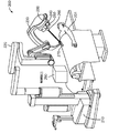
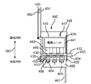
図3A及び図3Bは、エントリガイド・マニピュレータ230に取り付けられた4つの手術装置アセンブリ300を示す。図3Aでは、手術用装置アセンブリ300は、初期位置、例えば第1の位置に位置付けされる。以下でより完全に説明するように、機械的なインターフェイスは、器具マニピュレータアセンブリ240内のモータと手術用器具260の伝達ユニット内のシャフトとの間にディスク・スタックを含む。図3Aの構成では、第1の予圧力が、ディスク・スタックに加えられ、例えば、第1の所定の力が、ディスク・スタックに加えられる。
3A and 3B show four
第1の予圧力は、機械的なインターフェイスのディスク同士の間の相対運動を防止するために、ディスク・スタック内のディスクを一緒に十分緊密にクランプするのに十分ではないため、この第1の予圧力を用いると、機械的なインターフェイスは、ある程度のバックラッシュを有し得る。しかしながら、第1の予圧力と組み合された機械的なインターフェイスのディスク・スタック内のディスクの設計は、バックラッシュが最小化されるまで、ディスク・スタック内のディスクが、係合したままである、例えば部分的に結合したままであることを保証する。 The first pre-load is not sufficient to clamp the disks in the disk stack together tightly enough to prevent relative movement between the disks of the mechanical interface, and thus this first With preload, the mechanical interface may have some backlash. However, the design of the disks in the disk stack of the mechanical interface combined with the first preload causes the disks in the disk stack to remain engaged until backlash is minimized. , For example, ensuring that it remains partially bound.
低予圧力である第1予圧力を用いると、機械的なインターフェイス内のディスクは、第1のトルクレベル、例えば摩擦係数を0.1と仮定して1.17インチポンド(0.1322Nm)までのゼロバックラッシを有する。第1のトルクレベルを超えると、既知の小さなバックラッシュ、例えば1.13度のバックラッシュが存在し得る。以下でより完全に説明するように、ディスクを回転させて摩擦に打ち勝ち且つディスクを動的に素早くかみ合わせるのに十分な力が使用されるので、この力は、典型的には、第1のトルクレベルよりも大きいトルクレベルを供給する。この例では、機械的なインターフェイス内のディスクは、非ゼロバックラッシュを有する。こうして、機械的なインターフェイスは、この場合に、非ゼロバックラッシュを有すると言われる。 With the first preload, which is a low preload, the discs in the mechanical interface can move to a first torque level, eg, up to 1.17 in-lb (0.1322 Nm) assuming a coefficient of friction of 0.1. Has zero backlash. Above the first torque level, there may be a small known backlash, for example 1.13 degree backlash. As described more fully below, this force is typically used because sufficient force is used to rotate the disc to overcome friction and dynamically engage the disc quickly. Supply a torque level that is greater than the torque level. In this example, the disc in the mechanical interface has a non-zero backlash. Thus, the mechanical interface is said to have a non-zero backlash in this case.
図3Bでは、4つの手術用装置アセンブリのうちの3つが先端側に移動されている。矢印390は、先端方向及び基端方向を規定する。ここでは、先端方向は、患者201に向けてマスター器具マニピュレータ280から離れる方向である。基端方向は、患者201から離れてマスター器具マニピュレータ280に向かう方向である。
In Figure 3B, three of the four surgical device assemblies have been moved distally. The
手術用装置アセンブリ300が挿入アセンブリ331上で先端側に移動すると、ディスク・スタック上の予圧力は、第1の予圧力から第2の予圧力に自動的に増加する。第2の予圧力は、第2の所定の力の一例である。第2の予圧力は、外科処置で使用されるトルクレベルについて、機械的なインターフェイスのバックラッシュ、すなわちディスク・スタック内のディスク同士の間のバックラッシュをゼロに低減する。
As the
一態様では、第2の予圧力は、高予圧力、例えば2.3ポンド(1.043kg)である。今説明したように、機械的なインターフェイス内のディスク、従って機械的なインターフェイスは、外科処置で使用されるトルクレベルにおいてゼロバックラッシを有する。一例では、摩擦係数を0.1と仮定した場合に、機械的なインターフェイスは、トルクレベルについて最大4.9インチポンド(0.5537Nm)までゼロバックラッシュを有する。手術で有用な力をエンドエフェクタに加える手術用器具260について、特定のトルクを機械的なインターフェイス内のディスクに加えなければならない。これは、手術で有用なトルクとみなされる。一例では、手術で有用なトルクは、4.425インチポンド(0.5000Nm)であり、それによってこの態様では、機械的なインターフェイスは、外科処置に使用されるトルクレベルについてゼロバックラッシュを有する。
In one aspect, the second preload is a high preload, such as 2.3 pounds (1.043 kg). As just described, the disks within the mechanical interface, and thus the mechanical interface, have zero backlash at the torque levels used in the surgical procedure. In one example, assuming a coefficient of friction of 0.1, the mechanical interface has zero backlash for torque levels up to 4.9 inch pounds (0.5537 Nm). For the
以下でより完全に説明するように、従来技術とは異なり、バックラッシュの制御は、器具マニピュレータアセンブリ240内で行われる。以前では、バックラッシュは、使い捨ての滅菌アダプタアセンブリ内で制御されており、一実施例では、滅菌アダプタアセンブリが弾力特性を有する射出成形部品を含むことを必要としていた。バックラッシュの器具マニピュレータアセンブリ240内での移動制御には、機械加工部品を使用することができ、そのためバックラッシュを低減することができる。
Unlike the prior art, backlash control is performed within the
図4A〜4Gは、滅菌アダプタアセンブリ及び手術用器具を手術用器具マニピュレータアセンブリに取り付ける際のブロック図である。図4A〜図4Gに示される他の態様は、バックラッシュを減らすための予圧機構、器具取外しロックアウト、滅菌アダプタ取外しロックアウト、予圧解放、及び自動予圧リセットの操作を含む。図4A〜図4Gは、縮尺通りではない。図4A及び図4Gの矢印390は、図4A〜図4Gのそれぞれの図面における基端方向及び先端方向を示している。
4A-4G are block diagrams of attaching a sterile adapter assembly and a surgical instrument to a surgical instrument manipulator assembly. Other aspects shown in FIGS. 4A-4G include operations of preload mechanism to reduce backlash, instrument removal lockout, sterilization adapter removal lockout, preload release, and automatic preload reset. Figures 4A-4G are not to scale. The
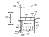
図4Aは、挿入アセンブリ431に固定された手術用器具マニピュレータアセンブリ440を示す。具体的には、器具マニピュレータアセンブリのハウジング448が、挿入アセンブリ431の先端部に固定して取り付けられるので、器具マニピュレータアセンブリのハウジング448は、挿入アセンブリ431の動きに伴って移動する。しかしながら、器具マニピュレータアセンブリのハウジング448内のモータパック446は、レール439上を移動することができる。モータパック446は、器具マニピュレータアセンブリのハウジング448に対して先端方向及び基端方向に移動することができる。モータパック446は、戻しばね447によって、器具マニピュレータアセンブリのハウジング448に結合される。
FIG. 4A shows surgical
モータパック446は、予圧アセンブリ480によって挿入アセンブリ431に移動可能に結合される。予圧アセンブリ480は、挿入アセンブリ431の予圧トラックに乗っている。以下でより完全に説明するように、予圧アセンブリ480が先端方向に移動する際に、予圧アセンブリ480は、先端方向の縦力をモータパック446に供給する。予圧アセンブリ480は、予圧解放ボタン482を含む。
モータパック446は、複数の駆動ユニット441を含む。複数の駆動ユニット441は、複数の駆動モータ及び複数の駆動出力アセンブリを含む。複数の駆動モータ内の各駆動モータは、複数の駆動出力アセンブリ内の対応する駆動出力アセンブリ443に結合される。
The
駆動出力アセンブリ443は、予圧ばねアセンブリ及び駆動出力ディスク445を含む。駆動出力アセンブリ443は、予圧ばねアセンブリと駆動出力ディスク445との間に位置付けされた低バックラッシュ・カプラも含む。駆動出力ディスク445は、入力ピンのセットにより、低バックラッシュ・カプラに結合される。以下でより完全に説明するように、駆動出力ディスク445は、先端面を含む円筒形状のディスクである。各駆動出力ディスク445の先端部は、駆動インターフェイスを有する。駆動インターフェイスは、駆動ドッグ及び位置合せ要素を含む。
駆動ドッグは、先端面から先端方向に延びる。各駆動ドッグは、先端面から延びる3次元構造、例えば3次元矩形構造を含む第1部分と、第1部分から延びる第2部分とを含む。駆動ドッグの第2部分は、第2部分の2つの対向する側面を含み、第2部分の側面のそれぞれは、湾曲面を含む。一態様では、湾曲面は、円形断面の一部、例えば円筒体の外面の一部である。 The drive dog extends from the tip surface in the tip direction. Each drive dog includes a first portion including a three-dimensional structure extending from the tip surface, for example, a three-dimensional rectangular structure, and a second portion extending from the first portion. The second portion of the drive dog includes two opposing sides of the second portion, each side of the second portion including a curved surface. In one aspect, the curved surface is part of a circular cross section, for example part of the outer surface of a cylinder.
モータパック446は、モータパック446の先端面から延びるように構成された複数のハードストップ437を含み、モータパック446は、解除ラッチを阻止する解除ラッチ阻止ストップ438も含む。解除ラッチ阻止ストップ438は、モータパック446の片側から先端方向に延びる。解除ラッチ435が、器具マニピュレータアセンブリのハウジング448の壁に取り付けられる。ラッチピン435Pが、解除ラッチ435の基端部に結合される。
図4Aは、予圧が解放された状態の器具マニピュレータアセンブリ440を示しており、例えばモータパック446は、完全な引込み位置にある。この構成では、戻しばね447が、モータパック446を器具マニピュレータアセンブリのハウジング448内に後退させるので、駆動出力ディスク445を含む複数の駆動出力ディスクは、器具マニピュレータアセンブリのハウジング448の先端面から延びていない。モータパック446の先端面は、完全な引込み位置である位置432にある。
FIG. 4A shows the
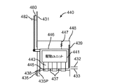
一態様では、モータパック446が完全な引込み位置432に位置するときに、制御装置290によって、挿入アセンブリ431を、予圧アセンブリ480が乗った予圧トラック上を移動させる。予圧トラックの運動によって、予圧アセンブリ480が、縦力をモータパック446に加えることになる。モータパック446上の縦力によって、モータパック446を器具マニピュレータアセンブリのハウジング448に対して先端側に位置433まで移動させ、それによって、図4Bに示されるように、駆動出力ディスク445を含む複数の駆動出力ディスクは、器具マニピュレータアセンブリのハウジング448の先端面から延びる。モータパック446が位置432にあるとすると、戻しばね447は、モータパック446が位置433にあるときに、その初期状態から伸長する。
In one aspect, the controller 290 causes the
手術用装置インターフェイス要素450、例えば滅菌アダプタを、図4Bに示されるように構成された器具マニピュレータアセンブリ440に取り付けることができる。しかしながら、手術用装置インターフェイス要素450をこの構成で取り付けるには、取付け作業中に、予圧ばねアセンブリを含む複数の予圧ばねアセンブリを駆動出力アセンブリ443内で圧縮させる必要がある。
A surgical
従って、一態様では、モータパック446が図4Bに示される位置にある場合に、手術用装置インターフェイス要素450を取り付ける前に、予圧解放ボタン482は、予圧機構408によってモータパック446に加えられた最初の縦力が解放されるように、起動される。結果として、戻しばね447は、図4Aに示されるように、モータパック446を完全な引込み位置432に引っ張る。
Thus, in one aspect, the
モータパック446が完全な引込み位置432にある状態で、一態様では、手術用装置インターフェイス要素450の一端上のタングが、器具マニピュレータアセンブリのハウジング448内の溝に位置付けされ、手術用装置インターフェイス要素450の他端が、図4Cに示されるように、その他端が解除ラッチ435と係合するまで、基端方向に移動される。モータパック446が完全に引き込まれた図4Cの構成では、解除ラッチ435の基端部を押した場合に、解除ラッチ435は、手術用装置インターフェイス要素450を解放し、及び手術用装置インターフェイス要素450を、器具マニピュレータアセンブリ440から取り外すことができる。しかしながら、一態様では、モータパック446が完全な引込み位置432にある間に、手術用器具を手術用装置インターフェイス要素450に取り付けた場合に、解除ラッチ435の操作は、予圧解放ボタン482が押された後まで、例えばこの予圧解放ボタンが起動されるまで、解除ラッチ阻止ストップ438によって阻止される。
With the
従って、この態様では、手術用装置インターフェイス要素450(図4C参照)は、器具マニピュレータアセンブリ440の先端面に取り付けられる。以下でより完全に説明するように、手術用装置インターフェイス要素450は、フレーム451及び可動式本体451Cを含む。可動式本体451Cは、フレーム451内で基端方向及び先端方向に移動することができる。複数の中間ディスクは、これら複数の中間ディスクのそれぞれが、フレーム451に対して回転できるように可動式本体451Cに取り付けられる。この態様では、複数のディスク内の各中間ディスクは同じであるので、中間ディスク453は、複数の中間ディスクのそれぞれのディスクを表す。
Thus, in this aspect, the surgical device interface element 450 (see FIG. 4C) is attached to the distal surface of the
複数の中間ディスクの各中間ディスク453は、被駆動中間インターフェイス455、第1の中間ディスクインターフェイス、及び駆動中間インターフェイス456、第2の中間ディスクインターフェイスを含む。被駆動中間インターフェイス455は、駆動中間インターフェイス456の反対側にあり且つこれから取り外される。一態様では、以下でより完全に説明するように、被駆動中間インターフェイス455は、第1の位置合せレセプタクル及び駆動ドッグ用レセプタクルを含む。駆動中間インターフェイス456は、駆動ドッグ及び係合構造を含む。
Each
被駆動中間インターフェイスの駆動ドッグ用レセプタクルのそれぞれは、被駆動中間インターフェイスの駆動ドッグ用レセプタクルのそれぞれが、第1平面によって二等分されるように、位置付けされる。駆動中間インターフェイスの駆動ドッグのそれぞれは、被駆動中間インターフェイスの駆動ドッグのそれぞれが、第2平面によって二等分されるように、位置付けされる。第1平面は、第2平面に直交する。 Each of the drive dog receptacles of the driven intermediate interface is positioned such that each of the drive dog receptacles of the driven intermediate interface is bisected by the first plane. Each drive dog of the drive intermediate interface is positioned such that each drive dog of the driven intermediate interface is bisected by the second plane. The first plane is orthogonal to the second plane.
被駆動中間インターフェイスの駆動ドッグ用レセプタクルのそれぞれは、外面から中間ディスク内に延びる対向した側壁を含む第1部分、底面を含む第2部分、及び第1部分から第2部分に延びる第3部分を含む。第3部分は、第3部分の2つの対向する側面を含み、第3部分の各側面は、傾斜面を含む。 Each of the drive dog receptacles of the driven intermediate interface includes a first portion including opposed sidewalls extending from the outer surface into the intermediate disc, a second portion including a bottom surface, and a third portion extending from the first portion to the second portion. Including. The third portion includes two opposite side surfaces of the third portion, and each side surface of the third portion includes an inclined surface.
駆動中間インターフェイスの駆動ドッグのそれぞれは、第1部分と、第1部分から延びる第2部分とを含む。第1部分は、3次元構造、例えば3次元矩形構造である。第2部分は、第2部分の2つの対向する側面を含み、第2部分の各側面は、湾曲面を含む。係合構造は、中間ディスクの先端面から先端方向に延びる開放3次元構造を含む。 Each of the drive dogs of the drive intermediate interface includes a first portion and a second portion extending from the first portion. The first portion has a three-dimensional structure, for example, a three-dimensional rectangular structure. The second portion includes two opposing side surfaces of the second portion, each side surface of the second portion including a curved surface. The engagement structure includes an open three-dimensional structure extending in the front direction from the front surface of the intermediate disc.
可動式本体451Cは、複数のハードストップ・レセプタクル457も含む。複数のハードストップ・レセプタクル457は、可動式本体451C内で可動式本体451Cの基端面から先端方向に延びる。
一態様では、器具マニピュレータアセンブリ440は、手術用装置インターフェイス要素450を器具マニピュレータアセンブリ440に取り付けたときの信号を制御装置290に送信するセンサを含む。この信号に応答して、制御装置290によって、挿入アセンブリ431を、予圧アセンブリ480が乗った予圧トラックを移動させ、それによって、予圧アセンブリ480は、リセットされ、且つ予圧アセンブリ480は、縦力をモータパック446に自動的に加える。モータパック446上の縦力によって、モータパック446を器具マニピュレータアセンブリのハウジング448に対して先端側に位置433まで移動させる。
In one aspect,
モータパック446を完全な引込み位置432から位置433に移動する際に、複数の駆動出力ディスクの各駆動出力ディスク445の駆動インターフェイスは、複数の中間ディスクの複数の被駆動中間インターフェイスの対応する被駆動中間インターフェイス455に接触し、次に、各中間ディスク453は、可動式本体451Cに接触する。可動式本体451Cがフレーム451内で可能な限り先端側に移動するときに、駆動出力ディスク445の先端方向の更なる動きが阻止される。
When moving the
結果として、モータパック446が位置433に移動し続けると、縦力に応じて、戻しばね447はさらに伸長され、複数の駆動出力アセンブリの各駆動出力アセンブリ443内の予圧ばねアセンブリは、予圧力が、複数の駆動出力ディスク内の各駆動出力ディスク445に作用するように圧縮される。予圧力によって、駆動出力ディスク445及び対応する被駆動中間インターフェイス455が押圧され、それによって予圧力は、手術用装置インターフェイス要素450内の複数の中間ディスクの各中間ディスク453に伝達される。この構成は、図4Dに示されている。
As a result, as
また、時には手術用装置インターフェイスと呼称される手術用装置インターフェイス要素450を、器具マニピュレータアセンブリ440に最初に取り付けたときに、被駆動中間インターフェイス455の要素は、駆動出力ディスク445上で駆動インターフェイスの対応する要素と位置合わせされないことがある。ディスク453及び445の要素が位置合わせされない場合に、これら2つのディスクは、駆動中間インターフェイス及び被駆動中間インターフェイスの機構によって一緒に部分的に結合されるが、2つのディスクは、互いに結合していない、例えばかみ合っていない。
Also, when the surgical
次に、制御装置290は、駆動出力ディスク445を回転させるための信号を器具マニピュレータアセンブリ440に送る。以下でより完全に説明するように、駆動出力ディスク455の駆動インターフェイスが中間ディスク453の被駆動中間インターフェイス445とかみ合うまで、中間ディスク453の回転が阻止され、駆動出力ディスク445が回転される。また、以下でより完全に説明するように、駆動出力ディスク445上の駆動インターフェイスの要素を中間ディスク453上の被駆動中間インターフェイス455の対応する要素と部分的に結合することによって、これら2つのディスクは、2つのディスクが回転する際に、予圧力の下で部分的に結合したままの状態となることを保証する。一態様では、2つのディスクを結合するときに、別のセンサが、ディスク・スタックの高さ変化を検出し、駆動出力ディスク445の回転を停止させるための信号を制御装置290に送る。2つのディスクのかみ合いを感知するための代替技術について以下で説明する。2つのディスクがかみ合うときに、ディスク・スタックの高さが低下するため、予圧力が低下する。
The controller 290 then sends a signal to the
モータパック446が位置433にあるときに、解除ラッチ阻止ストップ438は、解除ラッチ435に結合されたラッチピン435Pの前方に延びる。従って、誰かが解除ラッチ435の基端部を押して、手術用装置インターフェイス要素450を解放しようとした場合に、手術用装置インターフェイス要素450を解放するために解除ラッチ435を十分に旋回させることができないので、ラッチピン435Pは、手術用装置インターフェイス要素450を解放するのを防止する解除ラッチ阻止ストップ438に接触する。こうして、手術用装置インターフェイス要素450上に予圧力が存在する間は、手術用装置インターフェイス要素450を取り外すことができない。
When the
別の態様では、手術用装置インターフェイス要素450を器具マニピュレータアセンブリ440に取り付けるときに、信号が制御装置に送信されないので、モータパック446は、図4Cに示されるように、完全に解放された位置432に留まる。手術用器具460は、図4Bの構成又は図4Cの構成のいずれかで、器具マニピュレータアセンブリ440に結合される。例示の目的のために、図4Cの構成を使用する。
In another aspect, when the surgical
一態様では、手術用器具460の第1端部は、図4Eに示されるように、手術用器具460が適切な位置に保持されるまで、手術用装置インターフェイス要素450のフレーム451の斜面に沿って摺動される。一態様では、手術用器具460は、本体465及びメインチューブ467を含む。メインチューブ467は、本体465から先端側に延びる。本体465は、被駆動ディスク用レセプタクル463、シャフト466、及び被駆動ディスク464を含む。シャフト466及び被駆動ディスク464は、受け取ったトルクを器具を介して器具の1つ以上の構成要素に伝達する伝達ユニットの一部である。
In one aspect, the first end of
シャフト466の基端部は、被駆動ディスク用レセプタクル463内に延びており、被駆動ディスク464は、被駆動ディスク464が、被駆動ディスク用レセプタクル463に位置付けされるようにシャフト466の基端部に取り付けられる。被駆動ディスク464は、中間ディスク453の駆動中間インターフェイス456とインターフェイス接続する被駆動インターフェイスを含む。
The proximal end of the
被駆動ディスク464の被駆動インターフェイスは、係合レセプタクル、駆動ドッグ用レセプタクル、及び回転禁止要素を含む。駆動ドッグ用レセプタクルは、上述したものと同等である。回転禁止要素は、回転ロック機構を含む。回転禁止要素の係合の際に、回転ロック機構は、被駆動ディスク用レセプタクル464に係合し、且つ被駆動ディスク464の回転を防止する。
The driven interface of driven
手術用器具460を器具マニピュレータアセンブリ440に結合するときに、各被駆動ディスク464は、中間ディスク453が自由に回転できるように、手術用装置インターフェイス要素450内の対応する中間ディスク453を基端側に押圧する。これは、ディスク・スタック上の予圧力を増加させる。しかしながら、手術用器具460を手術用装置インターフェイス要素450に最初に取り付けるときに、駆動中間インターフェイス456の要素は、被駆動ディスク464上で被駆動インターフェイスの対応する要素と位置合わせされないことがある。2つのディスク453及び464の要素が位置合わせされない場合に、これら2つのディスクは、駆動中間インターフェイス456内の及び被駆動インターフェイス内の機構によって一緒に部分的に結合されるが、2つのディスクは、互いにかみ合っていない。
When coupling the
以下でより完全に説明するように、中間ディスク453の駆動中間インターフェイス456が、被駆動ディスク464の対応する被駆動インターフェイスと位置合わせされていない場合に、中間ディスク453の駆動中間インターフェイス456上の係合構造は、手術用器具460の被駆動ディスク464上で回転禁止要素に係合する。回転禁止要素は、回転ロック機構を含む。回転禁止要素の係合の際に、回転ロック機構は、被駆動ディスク用レセプタクル464に係合し、且つ被駆動ディスク464の回転を防止する。
As described more fully below, the engagement on the drive
手術用器具460を器具マニピュレータアセンブリ440に結合させるときに、器具マニピュレータアセンブリ440は、手術用器具460の存在を検出し、信号を制御装置290に送る。この信号に応答して、制御装置290は、駆動出力ディスク445を回転させるための信号を器具マニピュレータアセンブリ440に送る。中間ディスク453の駆動中間インターフェイス456が、所定の位置に固定された被駆動ディスク464と一緒に回転する際に、駆動中間インターフェイス456上の各要素は、被駆動ディスク464の被駆動インターフェイスの対応する要素と位置合わせされるように回転し、この対応する要素とかみ合う。駆動中間インターフェイス456と被駆動ディスク464上の被駆動インターフェイスとの結合によって、被駆動ディスク464上の回転ロックが解放される。こうして、ディスクのスタック、つまりディスク445,453,464は、ユニットとして回転する。ディスク453及び464を結合するときに、センサは、ディスク・スタックの高さ変化を再び検出し、駆動出力ディスク445の回転を停止させる信号を制御装置290に送る。ディスクのスタックがかみ合わされるときに、ディスク・スタックに加えられた予圧力は、第1の縦力、すなわち第1の予圧力と呼称される。
When coupling
上述した説明は、手術用器具460が、図4Dに示される構成で器具マニピュレータアセンブリ440及び手術用装置インターフェイス要素450に一緒に取り付けられると仮定した。しかしながら、別の態様では、器具マニピュレータアセンブリ440及び手術用装置インターフェイス要素450が図4Cに示された構成となる場合であって、手術用器具460を取り付けるときに、上述したように、センサは信号を制御装置に送信し、制御装置は、ディスク445,453,464が予圧力を下回るように予圧力を自動的にリセットする。次に、制御装置は、上述したのと同じ方法で、ディスクのスタックが位置合わせされ、かみ合う状態になり、及びユニットとして回転するように被駆動ディスク445を回転させる。従って、位置432及び433に対するモータパック446の初期位置に拘わらず、手術用器具460を取り付けるときに、得られる構成は、図4Eに示される。
The above description has assumed that
第1の縦力がモータパック446に加えられる図4Eの構成では、手術用装置インターフェイス要素450は、予圧を解放することなく取り外すことはできない。しかしながら、手術用器具460は、依然として取り外すことができる。以下でより完全に説明するように、一態様では、手術用器具460の両側に解除ボタンがある。解除ボタンを係合することによって、手術用器具460内の機構が手術用装置インターフェイス要素450内の可動式本体451Cを基端側に押し、それによって、中間ディスク453及び被駆動ディスク464の係合が解除され、手術用器具460を取り外すことができる。
In the configuration of FIG. 4E where the first longitudinal force is applied to the
挿入アセンブリ431に沿って器具マニピュレータアセンブリ440を移動させることにより、手術用器具460をカニューレ内に挿入する際に、第2の予圧力は、メインチューブ467に結合した端部要素がカニューレの先端部から突出する前に、予圧アセンブリ480によってディスク445,453,464のディスク・スタックに加えられる。特に、手術用器具460が先端側に移動する際に、予圧アセンブリ480は、予圧トラックに沿って先端側に移動する。以下でより完全に説明するように、器具マニピュレータアセンブリ440を所定の距離Zloadだけ先端側に移動するときに、予圧アセンブリ480によって、モータパック446を、所定の距離Zloadに加えて追加の距離Δを移動させ、それによってモータパック446は位置434となる。モータパック446の追加の距離Δの移動によって、複数の駆動出力アセンブリの各駆動出力アセンブリ443内の予圧ばねアセンブリが圧縮され、それによって、第2の予圧力が、複数の駆動出力ディスク内の各駆動出力ディスク545に作用する。第2の予圧力は、手術用器具260の先端部がカニューレから抜け出る前に、駆動ユニット441内のモータシャフトの回転と手術用器具460内のシャフト467の回転との間のバックラッシュを0.7度未満に低減する。
By moving the
モータパック446の追加の距離Δの移動によって、戻しばね447がさらに伸長され、加えて、複数のハードストップ437のそれぞれを、複数のハードストップ・レセプタクル457内の対応するハードストップ・レセプタクルに挿入させる。複数ハードストップ437は、手術用装置インターフェイス要素450内での可動式本体451Cのあらゆる基端側への移動を防止する。複数のハードストップ437及び複数のハードストップ・レセプタクル457の組合せは、手術用器具の取外しインターロックを形成し、手術用器具460の取り外しを防止する。使用者が解除ボタンを手術用器具460に係合しようとする場合に、手術用器具460内の機構は、複数のハードストップ437が、可動式本体451Cの基端側へのあらゆる移動を防止するので、手術用装置インターフェイス要素450内の可動式本体451Cを基端側に押すことはできず、それによって中間ディスク453及び被駆動ディスク464の係合を解除することはできない。
The movement of the
複数のハードストップ・レセプタクル457の使用は、単なる例示であり、限定するものではない。別の態様では、複数のハードストップ・レセプタクル457は、使用されない。代わりに、複数のハードストップ437が、可動式本体451Cの基端面に接触し、可動式本体451Cの基端方向への移動を防止する。
The use of multiple
いくつかの理由で、手術用器具460の先端チップがカニューレの先端部を越えて延びる間に、手術用器具460を取り外す必要がある場合に、使用者は、予圧解放ボタン482を押す。押されたときに、予圧解放ボタン482によって、モータパック446上の縦力が解放される。その結果、戻しばね447は、モータパック446を完全な引込み位置432に引っ張る。
For several reasons, the user depresses the
モータパック446が完全に引き込まれた状態で、複数のハードストップ437は、手術用装置インターフェイス要素450の可動式本体451C内の複数のハードストップ・レセプタクル467から後退され、ディスク453及び464は、もはや予圧力を受けていない。従って、手術用器具460上の解除ボタンを使用して、挿入アセンブリ431の任意の位置で手術用器具460を手術用装置インターフェイス要素450から取り外すことができる。加えて、解除ラッチ阻止ストップ438が引き抜かれ、及び解除ラッチ435を使用して、挿入アセンブリ431の任意の位置で手術用装置インターフェイス要素450を器具マニピュレータアセンブリ440から係合を解除することができる。一態様では、手術用装置インターフェイス要素450の解放は、予圧解放ボタン482が押された後まで阻止され、例えば解除ラッチ阻止ストップ438は、予圧解放ボタン482が押された後まで、解除ラッチ435の操作を阻止する。上述したように、予圧は、自動的にリセットされ、次回の手術用装置インターフェイス要素450が設置され、且つ挿入アセンブリ431が完全な退避位置に移動される。
With the
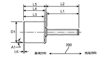
図5〜図13は、図3Aに示される構成を得るための手術用装置アセンブリ300の部品取付けの一態様を示す図である。図5は、器具マニピュレータアセンブリ240の先端部を示す。器具マニピュレータアセンブリ240は、駆動ユニットアセンブリ541及び駆動出力ユニット542を含む。この態様では、駆動出力ユニット542は、複数の駆動出力アセンブリ543P、例えば8つの駆動出力アセンブリを含む。ここで、駆動出力アセンブリ543は、8つの駆動出力アセンブリのいずれか1つを指す。一態様では、8つの駆動出力アセンブリのうちの6つのみが使用される。駆動出力アセンブリ543は、時にはカプラ544と呼称される低バックラッシュ・カプラ544、及び駆動出力ディスク545を含む。図16Aも参照されたい。一態様では、0.3度未満のバックラッシュを有するカプラは、低バックラッシュ・カプラとみなされる。
5 to 13 are views showing one aspect of component attachment of the
駆動出力ディスク545は、出力ピンのセットにより低バックラッシュ・カプラ544に結合される。以下でより完全に説明するように、駆動出力ディスク545は、先端面を含む円筒形状のディスクである。各駆動出力ディスク545の先端部は、駆動インターフェイス557を有する。駆動インターフェイス557は、駆動ドッグ及び位置合せ要素を含む。図5では、駆動ドッグと、第1及び第2の位置合せ要素とが、駆動出力ディスク545の先端面から先端方向に延びる(図16C参照)。
図6は、挿入アセンブリ331に固定され、次に挿入軸線ベースアセンブリ632に取り付けられる器具マニピュレータアセンブリ240を示す。挿入軸線ベースアセンブリ632は、挿入アセンブリ331を移動させるためのモータ及び電力機器を含む。
FIG. 6 shows the
滅菌アダプタアセンブリ250は、滅菌アダプタフレーム651及び滅菌ドレープ(図示せず)を含む。滅菌ドレープは、滅菌アダプタフレーム651に固定して取り付けられる。滅菌アダプタアセンブリ250は、手術用装置インターフェイス要素の一例である。滅菌アダプタフレーム651は、手術用装置インターフェイス要素本体の一例である。より一般的に言うと、手術用装置インターフェイス要素は、駆動システムの駆動インターフェイスと手術用器具の被駆動インターフェイスとの間に機械的なインターフェイスを含む構造である。
The
複数のタング652A,652Bが、滅菌アダプタフレーム651の第1端部651Aから延びる。第1端部651Aは、時には、滅菌アダプタアセンブリ250の及び滅菌アダプタフレーム651の閉鎖端とも呼称される。各タング652A,652Bは、駆動出力ユニット542の複数の溝内の対応する溝647Aと647Bにかみ合うように構成される。滅菌アダプタフレーム651の第2端部651Bは、滅菌アダプタフレーム651を駆動出力ユニット542に取り付けるときに、駆動出力ユニット542の滅菌アダプタ解除ラッチ635と係合するリップ654を含む。第2端部651Bは、時には、滅菌アダプタアセンブリ250の及び滅菌アダプタフレーム651の開放端とも呼称される。
A plurality of
以下でより完全に説明するように、滅菌アダプタフレーム651は、可動式本体651Cを含む。可動式本体651Cは、滅菌アダプタフレーム651内で基端方向及び先端方向に移動することができる。
As described more fully below, the
複数の中間ディスク653Pが、可動式本体651Cの複数の中間ディスクレセプタクルに取り付けられ、それによって、各中間ディスクは、滅菌アダプタフレーム651に対して及び可動式本体651Cに対して回転することができる。こうして、複数の中間ディスク653Pは、滅菌アダプタフレーム651に回転可能に取り付けられる。中間ディスク653は、複数の中間ディスク653P内の各中間ディスクを表す。中間ディスク653は、代表的な中間ディスクである。
A plurality of
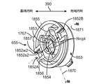
各中間ディスク653は、中間ディスク653の第1の側に被駆動中間インターフェイス655と、中間ディスク653の第2の側に駆動中間インターフェイス756(図7参照)とを含む。第1の側は、第2の側とは反対側にあり、且つ第2の側から取り外される。各中間ディスク653の被駆動中間インターフェイス655は、中間ディスク653が可動式本体651Cの中間ディスクレセプタクルに取り付けられた状態で、図6に確認することができる。被駆動中間インターフェイス655は、駆動出力ユニット542内の駆動出力ディスク545上で駆動インターフェイス557にかみ合うように構成される。
Each
滅菌アダプタアセンブリ250を器具マニピュレータアセンブリ240に取り付けるために、各タング652A,652Bは、駆動出力ユニット542の対応する溝647A,647B内に挿入される。図7Aを参照されたい。次に、滅菌アダプタフレーム651は、リップ654が滅菌アダプタ解除ラッチ635によって係合されるまで、回転される。要素652A,652Bをタングと呼称すること及び要素647A,647Bを溝と呼称することは、単なる例示であり、限定するものではない。あるいはまた、要素652A,652Bは、ほぞ(tenons)又は突出部として表すことができ、要素674A,647Bは、ほぞ穴(mortises)又は空洞として表すことができる。
To attach the
図7Bに示されるように、滅菌アダプタフレーム651を駆動出力ユニット542にラッチ掛けするときに、器具マニピュレータアセンブリ240のプランジャ546が、押し下げられる。プランジャ546が押し下げられるときに、滅菌アダプタアセンブリ250の存在を制御装置290に示す信号が生成される。この信号に応答して、手術システム200の制御装置290は、複数の駆動出力ディスク545P(図5参照)の各駆動出力ディスク545上で予圧力を生成する自動予圧リセット機構(図24B参照)に最初に通電し、次に制御装置は、複数の駆動出力ディスク545Pの各駆動出力ディスク545を回転させるための信号を器具マニピュレータアセンブリ240に送る。
As shown in FIG. 7B, when the
以下でより完全に説明するように、駆動出力ユニット542内の各駆動出力アセンブリ543は、ばねで付勢され、滅菌アダプタアセンブリ250を器具マニピュレータアセンブリ240に取り付けた後に、予圧力が各駆動出力ディスク545に作用するように自動的に位置付けされる。予圧力によって、駆動出力ディスク545、及び滅菌アダプタフレーム651内の中間ディスク653の対応する被駆動中間インターフェイス655が押圧される。
As will be described more fully below, each drive
しかしながら、図7Bでは、滅菌アダプタフレーム651を器具マニピュレータアセンブリ240に最初に取り付けるときに、被駆動中間インターフェイス655の要素は、駆動出力ディスク545上で駆動インターフェイス557の対応する要素と位置合わせされないことがある。2つのディスク653及び545の要素が位置合わせされない場合に、これら2つのディスクは、部分的に結合されるが、2つのディスクは、互いにかみ合わない。こうして、部分的に結合されるディスク545及び653、すなわち第1ディスク及び第2ディスクを含むディスク・スタックは、第1の高さを有する。予圧力がこのディスク・スタックに加えられた後に、制御装置は、駆動出力ディスク545を回転させる。
However, in FIG. 7B, when the
以下でより完全に説明するように、2つのディスクがかみ合うまで、中間ディスク653の回転は阻止されるが、駆動出力ディスク545は回転される。また、以下でより完全に説明するように、駆動出力ディスク545上の駆動インターフェイス557の要素を中間ディスク653上の被駆動中間インターフェイス655の対応する要素と結合することによって、駆動出力ディスク545を回転させながら、2つのディスクが、予圧力の下で部分的に結合したままの状態となることを保証する。一態様では、2つのディスクがかみ合わされたときに、ディスク・スタックの高さは、第2の高さを有し、第2の高さは、第1の高さ未満である。器具マニピュレータアセンブリ240内のセンサは、この高さ変化を検出し、駆動出力ディスク545の回転を停止させるための信号を制御装置290に送る。駆動出力ディスク及び中間ディスクのかみ合いを検出する別の方法ついて、以下で説明する。
The
図7Bは、駆動ユニットアセンブリ541内のモータパックに結合した予圧アセンブリ780も示している。予圧アセンブリ780は、予圧アセンブリ480の一態様のより詳細な例である。
FIG. 7B also shows a
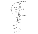
予圧アセンブリ780は、挿入アセンブリ331の予圧トラック(図22Aの予圧トラック2225参照)上に乗る。器具マニピュレータアセンブリのハウジング741及び器具滅菌アダプタアセンブリ250は、挿入アセンブリ331の先端部に固定して取り付けられ、且つ挿入アセンブリ331の先端部と一緒にユニットとして移動する。
The
しかしながら、器具マニピュレータアセンブリのハウジング741内のモータパック(図22A〜図22B参照)は、器具マニピュレータアセンブリのハウジング741に対して先端方向及び基端方向に移動することができる。より完全に説明するように、予圧アセンブリ780が先端方向に移動する際に、予圧アセンブリ780は、先端方向の縦力をモータパックに供給する。縦力は、第2の予圧力を生成する駆動出力アセンブリ543内のばねの圧縮をもたらす。第2の予圧力は、手術用器具260の先端部がカニューレを抜け出る前に、あらゆるバックラッシュを0.7度未満に低減する。
However, the motor pack within the instrument manipulator assembly housing 741 (see FIGS. 22A-22B) can be moved distally and proximally relative to the instrument
図7Aに戻ると、複数の中間ディスク653Pの中間ディスク653の先端側の駆動中間インターフェイス756が、示されている。また、滅菌アダプタフレーム651の内側面から延びる器具挿入スキッドプレート755Bを、図7A及び図7Bに確認することができる。滅菌アダプタフレーム651の反対側の内側面から延びる同様の器具挿入スキッドプレート755Aが存在する。図7A及び図7Bでは、時には、可動式本体651Cのリップ751Bと呼称される側面751Bも確認することができる。側面751Aは、図11に示される。
Returning to FIG. 7A, the drive
図8A〜図8Iは、手術用装置インターフェイス要素450の及び滅菌アダプタアセンブリ250の変形例の滅菌アダプタアセンブリ250Aを示す。滅菌アダプタアセンブリ250Aは、滅菌アダプタフレーム851及び滅菌ドレープ(図示せず)を含む。滅菌ドレープは、滅菌アダプタフレーム851に固定して取り付けられる。滅菌アダプタフレーム851は、手術用装置インターフェイス要素本体の一例である。
8A-8I show a
複数の溝852A,852B(図8H及び図8I参照)が、滅菌アダプタフレーム851の第1端部851内に延びており、第1及び第2のリップ852A1,852B1を形成する。第1端部851Aは、時には、滅菌アダプタアセンブリ250Aの及び滅菌アダプタフレーム851の閉鎖端と呼称される。各溝852A,852Bの深さ及びサイズは、腹側ラッチアセンブリ847の先端部上の対応するフック847A,847Bの面が、対応するリップ852A1,852B1と係合するのを可能にするように構成される。
A plurality of
第1及び第2のリップ852A1,852B1のそれぞれは、第1面及び第2面を含む。第2面は、第1面の反対側にあり、例えば、第1面は基端面であり、第2面は先端面である。リップの第2面は、軸線890に対して直交する方向でリップの第1面よりも長い。リップの第3面は、第1面と第2平面との間に延びており、第1及び第2面の異なる長さを考慮してテーパ形状に形成される。一態様では、第3面は、面取り面である。
Each of the first and second lips 852A1, 852B1 includes a first surface and a second surface. The second surface is on the opposite side of the first surface, for example, the first surface is the base end surface and the second surface is the tip end surface. The second surface of the lip is longer than the first surface of the lip in a direction orthogonal to the
滅菌アダプタフレーム851の第2端部851Bは、滅菌アダプタアセンブリ250Aを駆動出力ユニット542Aに取り付けるときに、駆動出力ユニット542Aの滅菌アダプタ解除ラッチ835の先端部から軸線890に向けて内向きに延びるリップ835Lによって係合されるようなリップ854を含む。第2端部851Bは、時には、滅菌アダプタアセンブリ250Aの及び滅菌アダプタフレーム851の開放端と呼称される。
The
リップ854は、第1面及び第2面を含む。第2面は、第1面の反対側にあり、例えば、第1面は基端面であり、第2面は先端面である。リップ854の第2面は、軸線890に対して直交する方向でリップ854の第1面よりも長い。リップ854の第3面が、第1面と第2面との間に延びており、第1面及び第2面の異なる長さを考慮してテーパ形状に形成される。一態様では、第3面は、面取り面である。
The
以下でより完全に説明するように、滅菌アダプタフレーム851は、可動式本体851Cを含む。可動式本体851Cは、滅菌アダプタフレーム851内で基端方向及び先端方向に移動することができる。器具挿入スキッドプレート855Aが、滅菌アダプタフレーム851の内側面から延びる。滅菌アダプタフレーム851の反対側の内側面から延びる同様の器具挿入スキッドプレート855Bが存在する。図8Aでは、時には可動式本体851Cのリップ851C1と呼称される側面851C1も確認することができる。
As described more fully below, the
可動式本体851Cの機構及び操作は、可動式本体651Cの機構及び操作と同じであるので、可動式本体651Cの機構及び操作についての説明は、可動式本体851Cについてここでは繰り返さない。また、手術用器具の滅菌アダプタ250Aへの取付けは、滅菌アダプタ250Aに関して説明したのと同様であるので、滅菌アダプタ250についての説明を繰り返さない。
Since the mechanism and operation of
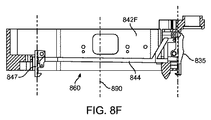
滅菌アダプタアセンブリ250Aを器具マニピュレータアセンブリ240に取り付けるために、滅菌アダプタアセンブリ250Aは、縦軸890に沿って軸線方向の基端方向に移動される、すなわち、以下でより完全に説明するように、滅菌アダプタアセンブリが駆動出力ユニット542Aの機構によって係合されるまで、矢印891(図8A及び図8B参照)によって示される方向に移動される。図8B〜図8Dは、滅菌アダプタアセンブリ250Aを駆動出力ユニット542Aに取り付ける際に使用する要素を示す断面図である。駆動出力ユニット542Aは、駆動出力ユニット542A内に含まれる滅菌アダプタアセンブリ250Aのラッチ機構860を除いて、駆動出力ユニット542と同様である。
To attach the
駆動出力ユニット542Aのフレーム842Fは、フレーム842Fの先端面から延びる、時には第1の位置合せ要素と呼称される第1の滅菌アダプタ位置合せ要素845Aと、フレーム842Fの先端面から延びる、時には第2の位置合せ要素とも呼称される第2の滅菌アダプタ位置合せ要素845Bとを含む。滅菌アダプタ位置合せ要素845Aは、腹側ラッチアセンブリ847に隣接しているがこの内側にあり、滅菌アダプタ位置合せ要素845Bは、滅菌アダプタ解除ラッチ835に隣接しているがこの内側にある。
The
滅菌アダプタアセンブリ250Aが駆動出力ユニット542Aの先端面の近接部に軸線方向に移動する際に、第1の滅菌アダプタ位置合せ要素845Aは、滅菌アダプタフレーム851の第1の滅菌アダプタ位置合せレセプタクル853A(図8H及び図8I参照)に入る、例えばこれと係合する。同様に、第2の滅菌アダプタ位置合せ要素845Bは、滅菌アダプタフレーム851の第2の滅菌アダプタ位置合せレセプタクル853Bに入る、例えばこれと係合する。位置合せ要素及びレセプタクルは、滅菌アダプタアセンブリ250Aを位置合わせするように構成され、それによって、滅菌アダプタアセンブリ250Aの基端方向への更なる運動によって、ラッチ機構860を滅菌アダプタアセンブリ250Aに係合させる。
As the
第1及び第2の位置合せ要素845A,845Bは、複数の滅菌アダプタ位置合せ要素の一例である。第1及び第2の位置合せレセプタクル853A,853Bは、複数の位置合せレセプタクルの一例である。従って、この態様では、駆動出力ユニット542A、従って器具マニピュレータアセンブリ240は、複数の滅菌アダプタ位置合せ要素を含み、滅菌アダプタアセンブリ250Aは、複数の位置合せレセプタクルを含む。あるいはまた、複数のレセプタクルは、駆動出力ユニット542Aに形成することができ、複数の位置合せ要素は、滅菌アダプタフレーム851の基端面から延びることができる。
The first and
滅菌アダプタアセンブリ250Aが基端方向にさらに移動する際に、フック847Aのテーパ面が、滅菌アダプタアセンブリ250Aのリップ852A1のテーパ面に接触し、及びフック847Bのテーパ面が、滅菌アダプタアセンブリ250Aのリップ852B1のテーパ面に接触する。同様に、滅菌アダプタ解除ラッチ835のリップ835Lのテーパ面が、滅菌アダプタアセンブリ250Aのリップ854のテーパ面に接触する。
As the
滅菌アダプタアセンブリ250Aの基端方向への更なる運動によって、滅菌アダプタ解除ラッチ835の先端部を駆動出力ユニット542Aの軸線890から外向きに離れる方向に旋回させ、且つ腹側ラッチアセンブリ847のフック847A,847Bを駆動出力ユニット542Aの軸線890から外向きに離れる方向に旋回させる。フック847A,847B及びリップ835Lがリップ852A1及び852B1を越えて先端側に移動した後であって、リップ835Lがリップ854及びフック847A,847Bを越えて先端側に移動した後に、リップ835Lは、リップ835Lがリップ854に係合し、フック847Aがリップ852A1に係合し、及びフック847Bがリップ852B1に係合するように軸線890に向けて内向きに旋回する。特に、各フックの基端面は、対応するリップの第2面に接触する。こうして、図8Dに示されるように、滅菌アダプタ250Aは、滅菌アダプタアセンブリ250を軸線890に沿って駆動出力ユニット542Aの先端面に向けて移動させることのみによって、駆動出力ユニット542Aに取り付けられる。
Further proximal movement of the
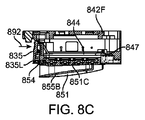
図8E〜図8Gは、滅菌アダプタラッチ機構860を示す断面図である。滅菌アダプタラッチ機構860を理解するために必要とされない要素は、図8E〜図8Gには含められていない。滅菌アダプタラッチ機構860は、駆動出力ユニット542Aのフレーム842Fに移動可能に結合される。滅菌アダプタラッチ機構860は、滅菌アダプタ解除ラッチ835、押込みロッド844、及び腹側ラッチアセンブリ847を含む。押込みロッド844は、滅菌アダプタ解除ラッチ835を腹ラッチアセンブリ847に結合し、それによってラッチ835の運動を腹側ラッチアセンブリ847に伝達させる。こうして、滅菌アダプタラッチ機構は、第1のラッチアセンブリ、第2のラッチアセンブリ、及び第1のラッチアセンブリを第2のラッチアセンブリに結合する押込みロッドを含む。
8E-8G are cross-sectional views showing a sterile
時にはラッチ835と呼称される滅菌アダプタ解除ラッチ835は、基端部(第1端部の一例)、及び先端部(第1端部の反対側の第2端部の一例)を含む。ラッチピン835P(図8B参照)が、ラッチ835の基端部の内面に結合される。ラッチピン835Pは、ラッチ835の内面から内向きに延びる。ラッチピン835Pは、ラッチピン435及びラッチピン2635Pと同様であるので、それらのラッチピンの説明は、ラッチピン835Pに直接的に適用可能であり、逆も同様に適用可能である。リップ835Lは、ラッチ835の先端部から内向きに延びる。この態様では、滅菌アダプタ解除ラッチ835は、フレーム842Fに旋回可能に接続される。この旋回接続は、ばねで付勢され、ラッチ835を旋回させる力が存在しないような係合位置又は係合状態と呼称される位置にラッチ835を維持する。押込みロッド844の第1端部は、ラッチ835の基端部分が内向きに押された、例えば第1方向に押されたときに、その運動が押込みロッド844に伝達されるように、ラッチ835の基端部分に旋回可能に接続される。
A sterile
この態様では、腹側ラッチアセンブリ847の基端部、例えば第1端部は、フレーム842Fに旋回可能に接続される。一態様では、フレーム842Fへの接続は、ばねで付勢され、腹側ラッチアセンブリ847を旋回させる力が存在しないような係合位置又は係合状態と呼称される位置に腹側ラッチアセンブリ847を維持する。2つの脚部が、腹側ラッチアセンブリ847の基端部から先端側に延びる。フック、すなわちフック847A及びフック847Bの一方が、各脚部の先端部に、例えば腹側ラッチアセンブリ847の先端部にある。押込みロッド844は、ラッチアセンブリ847の基端部と脚部の先端部との間で腹側ラッチアセンブリ847の一方の脚部に旋回可能に接続される。
In this aspect, the proximal end of the
この態様では、腹側ラッチアセンブリ847は、クラス3のレバーとして実装され、力点が、支点(フレームへの旋回接続点)と作用点(フック847A及び847B)との間にある。クラス3のレバーの使用は、単なる例示であり、これに限定するものではない。他の態様では、クラス1のレバー又はクラス2のレバーを使用することができる。クラス2のレバーについて、作用点が、支点と力点の間にあり、クラス1のレバーについて、支点が、力点と作用点との間にある。
In this aspect, the
図8Fに示されるように、外力が滅菌アダプタ解除ラッチ835に作用していない第1の状態で、滅菌アダプタ解除ラッチ835と腹側ラッチアセンブリ847との両方が、それぞれの縦軸が縦軸890と位置合わせされる、すなわち軸線890に対して略平行に位置合わせされた状態の安定状態の位置、つまり係合位置にある。ここで、略平行とは、製造公差内で平行であることを意味する。外力892がラッチ835の基端部に加えられる(図8G参照)、又は代替的に、力がリップ835Lに加えられる第2の状態では、ラッチ835の基端部分は、軸線890に向けて内向きに旋回され、及びラッチ835の先端部分は、外向きに旋回される。ラッチ835の動きに応答して、腹側ラッチアセンブリ847の先端部分は、外向きに旋回する。こうして、外力892によって、2つのラッチアセンブリを係合が解除された位置に移動させる、例えば第1の状態とは異なる第2の状態に移動させる。
As shown in FIG. 8F, in a first condition in which no external force is acting on the sterile
図8Hは、滅菌アダプタアセンブリ250Aの底面斜視図である。図8Iは、滅菌アダプタアセンブリ250Aの上面斜視図である。図8H及び図8Iには示されていないが、中間ディスク653は、可動式本体851C内の複数の中間ディスクレセプタクルのそれぞれに取り付けられる。滅菌アダプタアセンブリ250(図6参照)について、複数の中間ディスクは、可動式本体851Cの複数の中間ディスクレセプタクルに取り付けられ、それによって各中間ディスクは、滅菌アダプタフレーム851に対して及び可動式本体851Cに対して回転できるようになる。こうして、複数の中間ディスクは、滅菌アダプタフレーム851に回転可能に取り付けられる。複数の中間ディスクは、複数の中間ディスク653Pと同じであるので、複数の中間ディスクの特徴について、ここでは繰り返さない。また、可動式本体851Cに取り付けられた複数のディスク内の各中間ディスクは、中間ディスク653(図17B参照)と同じであるので、中間ディスク653の説明は、滅菌アダプタアセンブリ250Aに関して繰り返さない。
FIG. 8H is a bottom perspective view of
滅菌アダプタアセンブリ250Aの複数のハードストップ・レセプタクル857は、複数のハードストップ・レセプタクル1757と同じであり、複数のハードストップ・レセプタクル1757について説明したのと同じように動作するので、ここでは説明を繰り返さない。滅菌アダプタアセンブリ250Aは、各中間ディスクに関連付けられた中間ディスクのハードストップ861を有する。滅菌アダプタアセンブリ250Aの各中間ディスクのハードストップ861は、中間ディスクのハードストップ1761(図17B参照)と同じであり、中間ディスクのハードストップ1761について説明したのと同じように動作するので、その説明は、ここでは繰り返さない。
The plurality of
図9Aは、一態様では、手術用器具260のより詳細な図である。この態様では、手術用器具260は、被駆動インターフェイスアセンブリ961、伝達ユニット965、メインチューブ967、平行運動機構968、手首関節969、及びエンドエフェクタ970を含む。手首関節969は、例えば、(2002年6月28日に出願された、”Surgical Tool Having Positively Positionable Tendon-Activated Multi-Disk Wrist Joint”を開示する)米国特許出願公開第2003/0036748号に記載されており、この文献は、参照することにより本明細書に組み込まれる。平行運動機構968は、例えば、(2007年6月13日に出願された、”Surgical Instrument With Parallel Motion Mechanism”を開示する)米国特許第7,942,868号に記載されている。
FIG. 9A is, in one aspect, a more detailed view of
図9Bに示されるように、被駆動インターフェイスアセンブリ961は、複数の被駆動ディスク964Pを含む。複数の駆動ディスク964Pは、被駆動インターフェイス要素の一例である。被駆動ディスク964は、複数の被駆動ディスク964Pの各被駆動ディスクを表す。被駆動ディスク964は、伝達ユニット965のシャフトに取り付けられる。また、各被駆動ディスク964は、被駆動インターフェイスアセンブリ961の本体のレセプタクルに取り付けられる(図19B参照)。
As shown in FIG. 9B, the driven
伝達ユニット965内の機械部品(例えば、ギヤ、レバー、ジンバル、ケーブル等)は、複数の被駆動ディスク964Pからのトルクを、メインチューブ967を介してケーブル、ワイヤー、及び/又はケーブル、ワイヤー、及びハイポチューブの組合せで伝達させて、平行運動機構968、手首関節969、及びエンドエフェクタ970の運動を制御する。メインチューブ967は、実質的に剛性であるが、伝達ユニット967とエントリガイド270との間で僅かに曲げることができる。この屈曲によって、エントリガイド270内の器具本体の複数のチューブボアが、他の方法で可能となる伝達ユニットのサイズよりも互いに接近した状態で離間するのを可能にする。この屈曲は、手術用器具260がガイドチューブ270から引き抜かれるときに(メインチューブには、器具本体のロール運動を妨げるような恒久的な屈曲部が形成されてもよい)、メインチューブ967が直線形状となるような弾力性を有する。
Mechanical components within the transmission unit 965 (eg, gears, levers, gimbals, cables, etc.) transfer torque from the plurality of driven
被駆動インターフェイスアセンブリ961は、両側に取付けウイングのペア(962A1,962B1)及び(962A2,962B2)を有する。また、解除ボタン963A,963Bが、伝達ユニット965の両側にある。取付けウイング962B2及び解除ボタン963Bが、図10に示される。
The driven
手術用器具260を滅菌アダプタフレーム651に取り付けるために、まず、取付けウイング962A1,962A2を、滅菌アダプタフレーム651の開放端でスキッドプレート755A,755B(図10及び図11参照)に配置する。図11は、滅菌アダプタフレーム651の外側面が取り外された状態の図10の断面図である。
To attach the
取付けウイング962A1は、滅菌アダプタフレーム651の第1の側壁から延びるスキッドプレート755A上に載置される。手術用器具260が、スキッドプレート755Aの反対側の端部にある駐機スロット1155Aに向けてスキッドプレート755A上を摺動させる際に(図11参照)、第1の取付けウイング962A1,962A2の上面は、可動式本体651Cを基端方向に移動させるようなリップ751A,751Bの底縁に接触する(図12参照)。可動式本体651Cの基端側の動きは、器具マニピュレータアセンブリ240のプランジャ1246を基端方向に押し下げ、次に、手術用器具260が滅菌アダプタアセンブリ250の方に負荷を受けるような信号を制御装置290に発生させる。
The mounting wing 962A1 is mounted on a
取付けウイング962A1が、滅菌アダプタフレーム651の閉鎖端で駐機スロット1155Aに到達したときに(図13参照)、第1の取付けウイング962A1,962A2の上面は、もはやリップ751A,751Bの底縁と接触していない。その結果、可動式本体651C上の予圧力は、本体651Cを先端方向に移動させ(図13参照)、第1の取付けウイング962A1を所定の位置にロックする。第1の取付けウイング962A1が、滅菌アダプタフレーム651の閉鎖端に到達するときに、第2の取付けウイング962B1は、滅菌アダプタフレーム651の開放端の近くでスキッドプレート755Aの平坦部に載置される。
When the mounting wings 962A1 reach the
滅菌アダプタフレーム651内の各中間ディスク653は、複数の駆動出力ディスク545P上の予圧力によって軸線方向で先端方向に押される。こうして、手術用器具260が滅菌アダプタフレーム651に取り付けられる際に、複数の中間ディスク653Pは、第1の予圧力を可動式本体651Cに伝達し、それによって予圧力が、取付けウイング962A1に加えられる。この予圧力は、手術用器具260を滅菌アダプタフレーム651内で容易に摺動させることができるように、且つ小さな予圧力を全てのディスクで維持するように、選択される。
Each
手術用器具260を滅菌アダプタアセンブリ250に取り付けるときに、器具マニピュレータアセンブリ240は、手術用器具260の存在を検出し、手術用器具260の存在を示す信号を制御装置290に送る。この信号に応答して、手術システム200の制御装置290は、その信号を器具マニピュレータアセンブリ240に送り、複数の駆動出力ディスク545Pの各駆動出力ディスク545を回転させる。
When attaching
以下でより完全に説明するように、駆動出力ユニット542内の各駆動出力アセンブリ543は、ばねで付勢され、滅菌アダプタアセンブリ250を器具マニピュレータアセンブリ240に取り付けた後に、予圧力が各駆動出力ディスク545に作用されるように、自動的に位置付けされる。予圧力によって、駆動出力ディスク545、及び滅菌アダプタフレーム651内の中間ディスク655の対応する被駆動中間インターフェイス653が押圧される。
As will be described more fully below, each drive
しかしながら、図7Bでは、手術用器具260を滅菌アダプタアセンブリ250に最初に取り付けたときに、中間ディスク653の駆動中間インターフェイス765の要素は、被駆動ディスク964上の被駆動インターフェイス980の対応する要素と位置合わせされないことがある。2つのディスク653,964の要素が位置合わせされない場合に、これら2つのディスクは、部分的に結合されるが、2つのディスクは、互いにかみ合っていない。こうして、部分的に結合されたディスク964,653,545、すなわち第3ディスク、第2ディスク、及び第1ディスクを含むディスク・スタックは、第3の高さを有する。
However, in FIG. 7B, when the
手術用器具260を滅菌アダプタフレーム651に取り付けるときに、被駆動インターフェイスアセンブリ961内の各被駆動ディスク964は、滅菌アダプタアセンブリ250内の対応する中間ディスク653を基端側に押し、それによって中間ディスク653は、自由に回転することができる。以下でより完全に説明するように、滅菌アダプタアセンブリ250内の中間ディスク653の駆動中間インターフェイス756が、被駆動インターフェイスアセンブリ961内の被駆動ディスク964の対応する被駆動インターフェイス980と位置合わせされていないときに、中間ディスク653の駆動中間インターフェイス756上の係合構造は、手術用器具260の被駆動ディスク964上の回転禁止要素1980と係合し(図19A参照)、被駆動インターフェイスアセンブリ961内の被駆動ディスク964の回転を防止する。
As the
中間ディスク653の駆動中間インターフェイス756が、所定の位置に固定された被駆動ディスク964と一緒に回転する際に、駆動中間インターフェイス756上の各要素は、被駆動ディスク964の被駆動インターフェイス980の対応する要素と位置合わせするように回転され、この対応する要素とかみ合う。駆動中間インターフェイス756を被駆動インターフェイス980に結合することによって、被駆動ディスク964上の回転ロックが解除される。こうして、ディスクのスタックは、ユニットとして回転する。3つの全てのディスクがかみ合うときに、ディスク・スタックの高さは、第4の高さを有し、第4の高さは、第3の高さ未満である。器具マニピュレータアセンブリ240内のセンサは、この高さ変化を検出して、駆動出力ディスク545の回転を停止させる信号を制御装置に送る。ディスク・スタックの高さ変化を検出する器具マニピュレータアセンブリ240内のセンサは、機械式センサ、光センサ、誘導センサ、容量センサ等とすることができる。
As the drive
図14は、駆動出力ディスク545を中間ディスク653に結合し、中間ディスク653を被駆動ディスク964に結合したときの、ディスク・スタック1400を示す図である。ここで、結合したとは、2つのディスクがかみ合う、すなわち完全に結合するように、インターフェイス接続される2つのディスク上の全ての位置合わせ機構が位置合わせされることを意味する。上述したように、インターフェイス接続される2つのディスク上の一部の位置合せ機構が位置合わせされるが、インターフェイス接続される2つのディスク上の他の位置合せ機構が位置合わせされていないときに、インターフェイス接続される2つのディスクは、部分的に結合される。予圧力は、ある程度のバックラッシュにも拘わらず、全ての位置合せ機構が位置合わせされ且つかみ合うように、2つの部分的に結合したディスクを接触したままの状態にするように選択される。
FIG. 14 is a diagram showing a
ディスク・スタック1400は、図3A及び図3Bに関して先に示したディスク・スタック構成である。駆動出力ディスク545の駆動インターフェイス557は、中間ディスク653の被駆動中間インターフェイス655とかみ合い、中間ディスク653の駆動中間インターフェイス756は、被駆動ディスク964の被駆動インターフェイス980とかみ合う。以下でより完全に説明するように、ディスク1400のスタック上に高い予圧力、すなわち第2の予圧力が存在するときに、シャフト1466が駆動出力ディスク545に結合されたシャフトと正確に位置合わせされていない場合であっても、外科処置で使用されるトルクレベルについてディスク・スタック1400内のディスク同士の間にゼロバックラッシュを有する。ディスク1400のスタック内のディスク545,653,964を第2の予圧力の下でかみ合わせるときに、外科処置で使用されるトルクレベルについてディスク同士の間の結合部ではゼロバックラッシとなる。低バックラッシュ・カプラ544は、空間的な位置ずれを補償し、運動及びトルクをディスク・スタック1400に伝達する。以下でより完全に説明するように、駆動ドッグの設計は、駆動出力ディスク445と被駆動ディスク964との角度ずれを補償する。
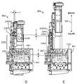
図15Aは、器具マニピュレータアセンブリのハウジング741を取り外した状態の器具マニピュレータアセンブリ240を示す図である。また、駆動ユニットアセンブリ541の要素を示す垂直方向の切断面である。器具マニピュレータアセンブリ240は、モータパック1541を含み、このモータパックは、複数の駆動ユニット1500P及び複数の駆動出力アセンブリ543Pを含む。複数の駆動ユニット1500Pの各駆動ユニット1500は、エンコーダ1501、スロットレス型ブラシレスサーボモータ1502、コンパクトなホール効果センサ1503、及び遊星減速機1504を含む。
FIG. 15A is a diagram showing the
一態様では、スロットレス型ブラシレスサーボモータ1502は、非常に高いモータ定数を有するので、サーボモータ1502は非常に効率的である。スロットレス型ブラシレスサーボモータの使用は、単なる例示であり、複数の駆動ユニット1500P内のモータをこの特定のタイプのモータに限定するものではない。使用される様々なモータは、ブラシ型モータ、ステッピングモータ等を含むことができる。各サーボモータ1502は、モータパック1541内の8つのサーボモータのコンパクトな構成を考慮して、隣接するサーボモータへのトルクリップルを防止するための磁気シールドを含む。
In one aspect, the
コンパクトなホール効果センサ1503を使用して、サーボモータ1502内の永久磁石の位置を検出する。ホール効果センサ1503は、第2のエンコーダとして使用される。エンコーダとホールとの間の(encoder to hall)照合は、エンコーダ1501及びホール効果センサ1503によって報告された回転位置を比較することで行われる。回転位置が著しく異なる場合に、エンコーダ1501、ホール効果センサ1503、又はこれらの間の機構に何らかの不具合がある。この照合が失敗したときに、制御装置内のソフトウェアを実行して、モータの電源を直ぐにオフにする。
A compact
遊星減速機1504は、高耐久性且つ高効率(90%以上)であり、従って、典型的な減速機よりもバック駆動(back-drive)が容易である。バック駆動可能とは、典型的な減速機と比較して、減速機の出力シャフトを比較的低いトルクで回転させることができることを意味する。
The
遊星減速機1504は、一態様では、1度未満のバックラッシュを有しており、別の態様では、例えば0.4度の低バックラッシュを有する。一態様では、4つの遊星減速機は、28:1の入出力比を有しており、標準的な遊星減速機と呼称される。この態様では、4つの遊星減速機は、9:1の入出力比を有しており、高速減速機と呼称される。同様に、標準的な遊星減速機を含む駆動ユニット1500は、標準的な駆動ユニットと呼称される。高速遊星減速機を含む駆動ユニット1500は、高速駆動ユニットと呼称される。
The
図15B〜図15Eは、モータパック1541で使用するのに適した遊星減速機の一例を示す図である。図15Bは、遊星減速機1504の側面図である。図15Cは、遊星減速機1504の先端側の図である。図15Dは、28:1の遊星減速機の基端側の図である。図15Eは、9:1の遊星減速機の基端側の図である。図15B〜図15Eの減速機の寸法の一例が、表1に示される。

図16A〜図16Dは、この態様では、複数の駆動出力アセンブリ543P内の各駆動出力アセンブリを表す駆動出力アセンブリ543のより詳細な図である。駆動出力アセンブリ543は、ボールスプライン1603を含む。軽予圧ばね1601、例えば第1の予圧ばねが、ボールスプライン1603の中央管腔に取り付けられ、且つ駆動出力ディスク545の基端側に取り付けられた一端を有する。ばね1601が圧縮されたときに、軽予圧ばね1601は、第1の予圧力を駆動出力ディスク545に加える。一態様では、第1の予圧力は、0.5重量ポンド(Lbf)(2.224N)である。
16A-16D are more detailed views of the
ボールスプラインナット1604が、ボールスプライン1603に取り付けられる。ボールスプラインナット1604は、ボールスプライン1603からのトルク/運動を伝達しながら、ボールスプライン1603に沿って基端側及び先端側に摺動する、すなわち、第1方向と、第1方向の反対側の第2方向とに摺動する。こうして、トルク/運動は、ボールスプライン1603を介して、時には屈曲部544と呼称される低バックラッシュ・カプラ544に伝達される。ボールスプライン1603は、駆動出力アセンブリ543をボールスプライン1603の縦軸に沿って移動させるのを可能にしながら、トルク/運動を伝達する。ディスクがディスク・スタック1400内で係合し又は係合が解除される際に、駆動出力アセンブリ543は、係合又は係合解除を容易にするためにボールスプライン1603に沿って内外に移動する。ボールスプライン1603は、外科処置で使用されるトルクレベルについてゼロバックラッシュを有する。
A
ボールスプラインナット1604は、重(heavy)予圧ばね1602、つまり第2の予圧ばねが、取り付けられるハウジング1605に挿入される。軽予圧ばね1601と組み合される重予圧ばね1602は、両方のばねが圧縮されたときに、第2の予圧力を駆動出力ディスク545に加える。一態様では、第2の予圧力は、2.3重量ポンド(Lbf)(10.23N)である。
The
屈曲部544は、トルクを駆動ユニットから屈曲部544に伝達する2つのピンによって駆動ユニットに結合される。屈曲部544は、2つのピンによって駆動出力ディスク545にも結合される。こうして、屈曲部544は、トルクを駆動ユニットから駆動出力ディスク545に伝達する。図16Bは、屈曲部544の端面図である。
屈曲部544は、駆動出力ディスク545の基端面から基端側に延びるシリンダ1445C(図14及び図16A参照)に収まる中央管腔1640を有する。屈曲部は、4つのビーム1641A,1641B,1641C,1641Dを有する。4つのビーム1641A,1641B,1641C,1641Dのそれぞれの第1端部は、屈曲部544の本体1642に接続される。4つのビーム1641A,1641B,1641C,1641Dのそれぞれの第2端部は、それぞれ中央ボアを有するシリンダ1643A,1643B,1643C,1643Dに接続される。ビーム1641A,1641B,1641C,1641Dは、中央管腔1640を通る軸線周りのねじりに剛性を有するが、側方オフセットに関して可撓性を有する。
駆動ユニットによって駆動される出力ピンが、シリンダ1643A,1643Bの中央ボアに取り付けられる。駆動出力ディスク545の入力ピンは、シリンダ1643C,1643Dの中央ボアに取り付けられる。
An output pin driven by the drive unit is attached to the central bore of the
一態様では、屈曲部544は、析出硬化型ステンレス鋼17−4H1150で作製された精密機械加工された一体部品である。屈曲部544のバックラッシュは、シリンダの中央ボアと、入力ピン又は出力ピンの外径との間の取付けピンのクリアランスによって決定される。この態様では、手術用装置アセンブリ300のバックラッシュは、器具マニピュレータアセンブリ240によってのみ制御される。これは、バックラッシュが、従来技術の滅菌アダプタ内のオルダム関節により考慮される以前のシステムとは対照的である。従来技術の滅菌アダプタの部品は、射出成形されたものなので、屈曲部544と同じ精度で製造することができない。手術用装置アセンブリ300、例えば器具マニピュレータアセンブリ240の再使用可能な部分でバックラッシュを制御することは、バックラッシュが手術用装置アセンブリ300の各回の使用について一貫しており、且つ従来技術の滅菌アダプタ等の単回使用の使い捨てアセンブリの射出成形部品の製造公差に依存しないことを意味する。
In one aspect,
屈曲部544は、中央管腔1640の軸線に直交する平面内での2つの自由度の動きに対応する。ビーム1641A,1641Bに結合した出力ピンは、軸線1690に沿って移動することができる。その可動域は、シリンダ1643A,1643Bの外面と本体1642の外面との間にギャップによって制限される。同様に、ビーム1641C,1641Dに結合した入力ピンは、軸線1690に直交する軸線1691に沿って移動することができる。その可動域は、シリンダ1643C,1643Dの外面と本体1642の外面との間のギャップによって制限される。一態様では、ビームを軸線1690,1691のうちの一方に沿って0.010インチ(0.254mm)を動かすには、0.66Lbf(2.934N)必要となり、1平方インチストレスあたり29,000ポンド(13154kg)をもたらす。100in-Lbf(11.3Nm)の加えられたトルクでは、ピークストレスは、1平方インチ当たり38,000ポンドであった。
屈曲部544の2つの自由度は、シャフトの位置ずれに対応する。特に、各屈曲部544が、駆動ユニット1500の対応する駆動シャフトと完全に同軸ではないシャフト1466(図14参照)を補償するために屈曲しながら、トルクを駆動出力ディスク545に伝達するため、駆動ユニットアセンブリ541は、モータパック1541内の駆動シャフトと伝達ユニット965内のシャフトとの位置ずれを許容することができる。
The two degrees of freedom of the
図16Cは、駆動出力ディスク545の駆動インターフェイス557、例えば駆動出力ディスク545の先端部の一態様のより詳細な図である。駆動出力ディスク545は、円筒形状の本体を有する。図16Dは、駆動ドッグ1652Aを含む出力ディスク545の断面図である。
FIG. 16C is a more detailed view of one aspect of
2つのボア1651A,1651Bが、駆動出力ディスク545を貫通して延びる。入力ピンが、各ボア1651A,1651Bに嵌合され、屈曲部544のシリンダ1643A,1643Bの対応するボア内に嵌合する。
Two bores 1651A, 1651B extend through the
2つの駆動ドッグ1652A,1652B、第1の位置合せ要素(センターポスト1653及びタブ1654)、第2の位置合せ要素(ピン1655)が、駆動出力ディスク545の先端面1656から先端側に延びる。センターポスト1653は、タブ1654の高さよりも大きい高さを有しているので、中間ディスク653の被駆動中間インターフェイス655内の対応する位置合せレセプタクルに対して駆動出力ディスク545をセンタ出しするのに役立つ。タブ1654は、センターポスト1653から先端面1656の周縁に向けて延びる。中心線1670,1671が、センターポスト1653を通って延びており、且つセンターポスト1653の中心で交差する。センターポスト1653及びタブ1654は、駆動出力ディスク545を中間ディスク653に位置合わせするのを補助する。センターポスト1653及びタブ1654は、かみ合わされたディスクのペアに安定性も提供する。
Two
この態様では、ピン1655は、中心線1670で中心決めされ、且つセンターポスト1653と先端面1656の縁部との間に位置付けされる。ピン1655は、シリンダのセグメントであり、例えばシリンダは、ピン1655の外面の一部が平坦であるが円筒形ではないように、ある面によって垂直に切断される。一態様では、ピン1655は、略3次元D字形状を有する。ここで、略3次元D字形状は、その形状が、3次元D字形状に十分に類似しており、3次元D字形状、例えばピン1655の形状として認識されることを意味する。ピン1655は、中間ディスク653の位置合せレセプタクルとかみ合うように構成される。
In this aspect,
第1及び第2の位置合せ要素の形状及び向きは、単なる例示であり、限定するものではない。位置合せ要素同士の間の他の形状及び位置合せ要素の他の向きは、第2の予圧力の下でバックラッシュが導入されない限り、使用することができ、これら要素は、係合及び係合解除するときに、結び付けられておらず、これらの要素は、かみ合わされたディスクのペアに安定性を提供する。 The shapes and orientations of the first and second alignment elements are merely exemplary and not limiting. Other shapes between the alignment elements and other orientations of the alignment elements can be used as long as backlash is not introduced under the second preload, these elements engaging and engaging Upon disengagement, these elements are untied and provide stability to the mated disc pairs.
駆動インターフェイス557は、2つの駆動ドッグ1652A,1652Bを含む。駆動ドッグ1652A,1652Bのそれぞれは、先端面1656から先端側に延びる。駆動ドッグ1652A,1652Bのぞれぞれは、駆動出力ディスク545の縦軸から同じ半径方向距離Rdogにある。駆動出力ディスク545の縦軸は、センターポスト1653の中心を通って延びる。また、各駆動ドッグ1652A,1652Bは、基端面1656の周縁部に近接している。半径方向に等距離にある駆動ドッグ1652A,1652Bの組合せ及び駆動ドッグ1652A,1652Bの周縁部に隣接した位置決めによって、駆動ドッグ1652A,1652Bが、トルク/運動を中間ディスク653に効率的に伝達するのを可能にする。
The
先端面1656の周縁に対する駆動ドッグ1652A,1652Bの位置は、中間ディスク653上の駆動ドッグ用レセプタクルの位置(図18A参照)によって決定される。中間ディスク653の直径は、滅菌アダプタアセンブリ250の可動式本体651Cに嵌合することができる中間ディスク653の数によって部分的に決定される。駆動ドッグ1652A,1652Bは、以下でより完全に説明するように、駆動ドッグ1652A,1652Bが中間ディスク653内の駆動ドッグ用レセプタクルに係合するようにサイズ決め及び位置付けされ、それによって駆動ドッグ1652A,1652Bは、可動式本体651Cの側壁に接触しない。
The positions of the drive dogs 1652A and 1652B with respect to the peripheral edge of the
図16Cに示されるように、駆動ドッグ1652A,1652Bは、駆動出力ディスク545のy軸1670及び縦軸(図示せず)を含む平面に対して鏡面対称を有する。駆動出力ディスク545の縦軸は、センターポスト1653の中心において軸線1670及び軸線1671の両方に対して直交する。
As shown in FIG. 16C, the drive dogs 1652A, 1652B have mirror symmetry with respect to a plane including the y-
駆動ドッグ1652A,1652Bのそれぞれは、駆動出力ディスク545のx軸1671及び縦軸を含む平面に対して鏡面対称を有する。この平面は、駆動ドッグ1652A,1652Bのそれぞれを二等分する。
Each of the drive dogs 1652A and 1652B has a mirror symmetry with respect to a plane including the
駆動ドッグ1652A,1652Bのサイズは、強度要件に基づいて選択される。この用途の駆動ドッグ1652A,1652Bの(中心から縁部までの半径方向の)長さは、ディスク545の中心での位置合せ機構/回転防止機構のサイズの制約によって決定され、及び駆動ドッグ1652,A1652Bの高さは、第1及び第2の両方の予圧力の下で、中間ディスク653との適切な係合を確保しつつ、機構のサイズ及び重量を低減するために最小化される。
The size of the drive dogs 1652A, 1652B is selected based on strength requirements. The length (in the radial direction from the center to the edge) of the drive dogs 1652A, 1652B for this application is determined by the size constraints of the alignment/anti-rotation mechanism at the center of the
駆動ドッグ1652Aは、駆動ドッグ1652Bと同じであるので、駆動ドッグ1652Aの特徴についてのみ、さらに詳細に検討する。駆動ドッグ1652Aの説明は、駆動ドッグ1652Bに直接的に適用可能であるので、その説明は、駆動ドッグ1652Bについて繰り返さない。
Drive
駆動ドッグ1652Aは、第1部分1652A1及び第2部1652A2を有する。第1部1652A1は、先端面1656から第2部分1652A2に先端側に延びる。第2部分1652A2は、第1部分1652A1から先端方向に延びる。
The
駆動ドッグ1652Aの第1部分1652A1は、3次元矩形構造であるので、先端面1656から延びる4つの直線状の側面、例えば図16Dの側面1652s2,1652s4を有する。本明細書中で、直線状は、駆動ドッグ1652Aの縦軸と、x軸1671及びy軸1670の一方とを含む平面に対して略平行であることを意味する。選択された軸線は、検討される3次元矩形構造の側面に依存する。略平行は、製造公差の範囲内で平行であることを意味する。
The first portion 1652A1 of the
第2部分1652A2(図16D参照)は、湾曲面である2つの対向する側面1652cyl2,1652cyl4を含む。一態様では、湾曲面は、円形断面の一部、例えば、シリンダ1658の外面の一部である。側面1652cyl2,1652cyl4は、エッジ1652e1,165e2を含み且つ図16Dの外側に延びる2つの平行な平面によって交差するシリンダの断面の外面である。従って、側面1652cyl2,1652cyl4は、湾曲面である。
The second portion 1652A2 (see FIG. 16D) includes two opposing side surfaces 1652cyl2 and 1652cyl4 that are curved surfaces. In one aspect, the curved surface is a portion of a circular cross section, eg, a portion of the outer surface of
一態様では、シリンダ1658は、0.125インチ(3.175mm)の直径を有する。シリンダ1658の軸線は、図16Dの外側に延びる。この態様では、第2断面1652A2の他の2つの側壁は、直線状の側面である。
In one aspect, the
一態様では、駆動出力ディスク545は、射出成形されたディスクである。駆動出力ディスク545は、ポリカーボネート、ポリフェニルスルホン(PPSU)、ポリエチレンイミン(PEI)等から作製することができる。
In one aspect, drive
図17Aは、滅菌アダプタアセンブリ250の別の例である。滅菌ドレープ(図示せず)が、リム1751に固定して取り付けられ、例えば、両面テープで貼り付けられる。滅菌ドレープは、公知であるので、さらに詳細には説明しない。例えば(2005年12月20日に出願された)米国特許第7,666,191号、(2006年3月31日に出願された)米国特許第7,699,855号、(2010年8月12日に出願された)米国特許出願公開第2011/0277775号明細書、及び(2010年8月12日に出願された)米国特許出願公開第2011/0277776号明細書を参照されたい。これら全ての文献は、参照することにより本明細書に組み込まれる。滅菌ドレープは、システム200の少なくとも一部をドレープで覆って、外科処置中に滅菌場所を維持する一方、滅菌アダプタアセンブリ250は、手術用器具260とその関連する器具マニピュレータアセンブリ240との間の正確で機械的なインターフェイスと共に、効率的且つシンプルな器具の交換も提供する。
FIG. 17A is another example of a
上述したように、可動式本体651Cは、滅菌アダプタフレーム651に取り付けられ、それによって、可動式本体651Cは、基端方向及び先端方向に移動することができる、すなわち、滅菌アダプタフレームに対して第1方向と、第1方向とは反対側の第2方向に移動することができる。図17Aでは、可動式本体651Cは、最も先端側の位置にある。可動式本体651Cは、複数の中間ディスク653P内の各中間ディスク653についてレセプタクルを含む。可動式本体651Cは、複数のハードストップ・レセプタクル1757も含む。各中間ディスク653は、円筒形状の本体を有する。
As mentioned above, the
一態様では、滅菌アダプタフレーム651、可動式本体651C、及び複数の中間ディスク653Pのそれぞれは、射出成形によって作製される。滅菌アダプタフレーム651、可動式本体651C、及び複数の中間ディスク653Pに適した材料は、ポリカーボネート、ポリフェニルスルホン(PPSU)、ポリエチレンイミン(PEI)等を含む。
In one aspect, each of the
各中間ディスク653は、可動式本体651Cの対応するレセプタクルに取り付けられる。各中間ディスク653は、レセプタクル内で回転することができ、且つレセプタクル内で先端側及び基端側に移動することができる。図17Aでは、中間ディスク653は、最も先端側の位置にある。図17Bは、可動式本体651C部分の拡大図であり、中間ディスク用レセプタクル1766及び中間ディスク653を示す。中間ディスク653は、ディスク653の外側面から延びるとともにディスク653の基端面から延びるタブ1767を有する(図18A参照)。中間ディスク653は、中間ディスクのハードストップ1761に関連付けされると言われる。これは、タブ1767が、ハードストップ1761に接触し、この接触の際に、中間ディスク653の回転が停止されることを意味する。
Each
手術用器具260を滅菌アダプタアセンブリ250に取り付けるときに、中間ディスク653は、可動式本体651Cに対して基端側に変位される。この位置では、タブ1767の最も先端側の部分、つまりタブ1767の底部は、ハードストップ1761の最も基端側の部分、つまりストップ1761の上部より上にあり、それによって中間ディスク653は、自由に回転し、且つハードストップ1761と接触しない。
When attaching
図18A及び18Bは、中間ディスク653の被駆動中間インターフェイス655(図18A参照)及び駆動中間インターフェイス756(図18B参照)を示す図である。被駆動中間インターフェイス655(図18A参照)は、中間ディスク653の基端部にある。被駆動中間インターフェイス655は、第1の位置合せレセプタクル及び第2位置合せレセプタクルを含む。この態様では、第1の位置合せレセプタクルは、センターポスト・レセプタクル1853とタブ・レセプタクル1854との組合せである。第2の位置合せレセプタクルは、ピン・レセプタクル1855である。
18A and 18B are diagrams showing a driven intermediate interface 655 (see FIG. 18A) and a driving intermediate interface 756 (see FIG. 18B) of the
センターピン・レセプタクル1853とタブ・レセプタクル1854との組合せは、ポスト1653及びタブ1654が、それぞれ、レセプタクル1853及びレセプタクル1854に位置合わせされるときに、センターポスト1653とタブ1654との組合せとかみ合うように構成される。同様に、ピン・レセプタクル1855は、それら2つが位置合わせされるときに、ピン1655にかみ合うように構成される。こうして、駆動出力ディスク545は、ディスク545の位置合せ要素が、中間ディスク653の位置合せレセプタクルと位置合わせされるときに、中間ディスク653と一方向でのみかみ合うことができる。
The combination of
被駆動中間インターフェイス655は、2つの駆動ドッグ用レセプタクル1852A,1852Bを含む。図18Aに示されるように、駆動ドッグ用レセプタクル1852A,1852Bは、中間ディスク653のy軸1870及び縦軸(図示せず)含む平面に対して鏡面対称を有する。中間ディスク653の縦軸は、両方の軸線1870及び軸線1871に直交する。
The driven
駆動ドッグ用レセプタクル1852A,1852Bのそれぞれは、中間ディスク653のx軸1671及び縦軸を含む平面に対して鏡面対称を有する。この平面は、駆動ドッグ用レセプタクル1852A,1852Bのそれぞれを二等分する。
Each of the
各駆動ドッグ用レセプタクルは、中間ディスク653の縦軸から同じ距離Rrcptにある内縁面を有する。以下でより完全に説明するように、この内縁面は、駆動ドッグ用レセプタクルの第3側面を形成する。駆動ドッグ用レセプタクル1852Aが駆動ドッグ用レセプタクル1852Bと同じであるため、駆動ドッグ用レセプタクル1852Aの特徴についてのみ、さらに詳細に検討する。駆動ドッグ用レセプタクル1852Aの説明は、駆動ドッグ用レセプタクル1852Bに直接的に適用可能であるので、その説明は、駆動ドッグ用レセプタクル1852Bについて繰り返さない。
Each drive dog receptacle has an inner edge surface at the same distance Rrcpt from the longitudinal axis of the
駆動ドッグ用レセプタクル1852Aは、4つの側面で境界を区切ることができる。一態様では、第1側面は、存在しないので、第1側面は、開放していると言われる。開放側壁の使用は、単なる例示であり、限定するものではない。いくつかの態様では、第1の側壁は、固体(中実)側壁とすることができる。第2側面及び第4側面は、第1側面に対して垂直な壁である。第3側面は、第2側面及び第4側面に対して垂直な壁である。従って、この態様では、駆動ドッグ用レセプタクル1852Aは、中間ディスク653内で中間ディスク653の基端側の外縁面1856から駆動ドッグ用レセプタクル1852Aの底面1857まで先端側に延びる3つの壁によって境界が区切られる。開放側とは反対側の第3の壁は、基端側の外縁面1856から底面1857に延びる直線状の壁である。対向する2つの壁、つまり第2及び第4の壁は、以下で説明するように、2つの部分、つまり直線状の壁部及び傾斜した壁部を有する。
The
図18Cは、x軸1871に直交する中心線に沿って切断された駆動ドッグ用レセプタクル1852Aの断面図である。駆動ドッグ用レセプタクル1852Aは、第1部分1852A1及び第2部分1852A2に分割される。第1部分1852A1は、中間ディスク653内で基端側の外面1856から第2部分1852A2に延びる。第2部分1852A2は、中間ディスク653内で駆動ドッグ用レセプタクル1852Aの第1部分1852A1から底面1857にさらに延びる。
FIG. 18C is a cross-sectional view of the
駆動ドッグ用レセプタクル1852Aの第1部分1852A1の境界を区切る対向する壁は、直線状の壁1852s2,1852s4である。典型的には、第1部分1852A1の高さは、駆動ドッグ1652Aの部分1652A1の高さ未満であり、それによって駆動出力ディスク545の先端側の縁面と中間ディスク653の基端側の縁面との間にある程度の空間が存在する。
The opposing walls that delimit the boundary of the first portion 1852A1 of the
第2部分1852A2(図18C参照)が、楔形状の外側面の一部である2つの対向する側壁1852w2,1852w4によって境界が区切られる、すなわち、側面1852w2,1852w4は、傾斜した平面である。側壁1852w2,1852w4は、角度αを定める。側面1852w1,1852w2は、2つの平行な平面、例えばライン1852e1を含む平面と底面1857を含む平面とにより交差される楔形状の表面部分である。これら両方の平面は、図18Cの外側に延びる。
The second portion 1852A2 (see FIG. 18C) is bounded by two opposing sidewalls 1852w2, 1852w4 that are part of the wedge-shaped outer surface, that is, the sides 1852w2, 1852w4 are sloping planes. The side walls 1852w2, 1852w4 define an angle α. The side surfaces 1852w1 and 1852w2 are wedge-shaped surface portions that are intersected by two parallel planes, for example, a plane including the line 1852e1 and a plane including the
一態様では、楔形状の一部は、駆動ドッグ1652Aの先端部をレセプタクル1852内に完全に挿入したときに、駆動ドッグ1652Aの先端面が底面1857に接触しないように選択され、シリンダ1658の円筒形状の側壁部分は、傾斜した側壁1852w2,1852w4に接触する。一態様では、シリンダ1658の0.125インチ(3.175mm)の直径について、角度αは、30度であるので、側壁1852w2,1852w4は、30度の楔形状の側面の部分となる。
In one aspect, a portion of the wedge shape is selected such that the leading edge of the
滅菌アダプタアセンブリ250を器具マニピュレータアセンブリ240に取り付けるときに、中間ディスク653上の被駆動中間インターフェイス655の向きに対する駆動出力ディスク545上の駆動インターフェイス557の向きは、既知ではない。しかしながら、これら2つのインターフェイスの相対的な向きに関係なく、駆動出力ディスク545上の予圧力は、中間ディスク653が、可動式本体651Cのレセプタクル1766(図17B参照)に最も先端側の部分で位置付けされる、例えば、インターフェイスディスク653が、第1の軸線方向位置となるように、中間ディスク653を先端側に押す。以下でより完全に説明するように、手術用器具260を滅菌アダプタアセンブリ250に取り付けるときに、インターフェイスディスク653は、第2の軸線方向位置に対して基端側に変位される。
The orientation of the
上述したように、滅菌アダプタアセンブリ250を器具マニピュレータアセンブリ240に取り付けることによってプランジャ546が押し下げられた後に、駆動出力ディスク545は、回転される。駆動出力ディスク545及び中間ディスク653が、接触して且つ部分的に結合されるので、駆動出力ディスク545の回転によって、中間ディスク653が回転する。こうして、インターフェイス557及び655は、位置合わせされ且つかみ合わされる、又は中間ディスク653上のタブ1767は、ハードストップ1761に接触する。タブ1767がハードストップ1761に接触するときに、中間ディスク653の回転は、停止される。インターフェイス557及び655がかみ合わされておらず且つ中間ディスク653の回転が停止されるときに、駆動出力ディスク545は、2つのインターフェイスがかみ合うまで回転し続ける。こうして、ディスク545及び653が結合され、駆動出力ディスク545の回転がハードストップ1761で停止されるという結果となる。制御システムは、駆動出力ディスク545の回転の停止を使用して、駆動出力ディスク545の向きを決定する。2つのディスクがハードストップ1761に到達する前にかみ合った場合であって、ハードストップ1761が到達したときに、2つのかみ合わされたディスクの回転は、停止される。
As described above, drive
図18Dは、駆動出力ディスク545上の駆動インターフェイス557が、中間ディスク653上の被駆動中間インターフェイス655と部分的に結合した後に、軽予圧力の下で駆動ドッグ用レセプタクル1852Aに挿入された駆動ドッグ1652Aを示す断面図である。上述したように、駆動ドッグ1652Aは、直線状の側面を含む第1部分1652A1を有する。第1部分1652A1の直線状の側面は、上述したように、第2部分1652A2、つまり円筒形状のチップに融合される。駆動ドッグ用レセプタクル1852Aは、直線状の内側壁を含む第1部分1852A1も有する。第1部分1852A1は、上述したように、テーパ状の内壁を含む第2部分1852A2に融合される。
FIG. 18D illustrates a drive dog inserted into
駆動ドッグ1652Aの先端部の両側の湾曲面、及び駆動ドッグ用レセプタクル1852A2の先端部上の対応する両側の傾斜した摺動壁(傾斜した側壁は、湾曲した側面に接する)は、単なる例示であり、限定するものではない。駆動ドッグ1652Aの先端部上の及び駆動ドッグ用レセプタクル1862の対応する先端壁部上の他の面は、高予圧力、つまり第2の予圧力の下で、外科処置で使用されるトルクレベルについて駆動出力ディスク545と中間ディスク653との間の回転方向でバックラッシゼロである限り、且つ2つのディスク同士の間のインターフェイスが角度ずれを補償する限り、使用することができる。
The curved surfaces on both sides of the tip of the
レセプタクル1852Aのテーパ壁と駆動ドッグ1652Aの先端チップ1652A2上の円筒形状の表面とにより、適切な力が、駆動出力ディスク545及び中間ディスク653を所定の位置に保持するために必要とされ、それによってトルク/運動が駆動出力ディスク545によって加えられるときに、2つのディスクが適切に機能する一方、2つのディスクは、部分的に結合される。この力が存在しない場合には、加えられたトルクはそれら駆動出力ディスク545及び中間ディスク653を離した状態で駆動することができるので、駆動出力ディスク545及び中間ディスク653を分離することができる。
Due to the tapered wall of the
軽予圧力の下でこの分離を防止するために、駆動ドッグ1652A及び駆動ドッグ用レセプタクル1852Aの両方は、上述したように、直線状の壁を含む第1部分を有する。駆動ドッグ1652A及び駆動ドッグ用レセプタクル1852Aがトルクの下で分離を開始する際に、図18Cに示されるように、直線状の壁部は、互いに接触する。この時点で、駆動ドッグ1652A及び駆動ドッグ用レセプタクル1852Aは、もはやこれら駆動ドッグ1652A及び駆動ドッグ用レセプタクル1852Aを離れるように駆動することができず、その動きは、駆動ドッグ1652Aが駆動ドッグ用レセプタクル1852A内に完全に挿入され且つ結合されることなく、既知の又は制御されたバックラッシュレベルで継続することができる。一態様では、軽予圧力の下で、バックラッシュの既知のレベルは、1.13度である。こうして、駆動出力ディスク545と中間ディスク653との間の部分的な結合部は、軽予圧力の下で既知のバックラッシュレベルを有する。
To prevent this separation under light preload, both drive
また、図18Dに示されるように、ディスク545を駆動するシャフトと中間ディスク653によって駆動されるシャフトとの間の少量の位置ずれを許容することができる。また、角度ずれは、図18Dのページの内外にある融合されるシリンダ1658の軸線によって規定される方向に許容することができる。
Also, as shown in FIG. 18D, a small amount of misalignment between the shaft driving the
駆動ドッグ1652A及び駆動ドッグ用レセプタクル1852Aを、高予圧力、例えば第2の予圧力の下で一緒にかみ合わせるときに、以下でより完全に説明するように、2つのディスク同士の間のインターフェイスにはバックラッシュは存在しない。第2の予圧力は、トルク/運動が加えられたときに、駆動ドッグ1652A及び駆動ドッグ用レセプタクル1852Aを物理的に離して後退及び分離するのを維持するのに十分である。こうして、この接合部は、バックラッシュなしに、トルク/運動を伝達することができる。第2の予圧力の下で、駆動出力ディスク545と中間ディスク653との間の結合部は、外科処置で使用されるトルクレベルについてゼロバックラッシュを有する。
When the
図18Bは、中間ディスク653の先端部での駆動中間インターフェイス756のより詳細な図である。駆動中間インターフェイス756は、駆動ドッグ1862A,1862B、及び係合構造1863を含む。
FIG. 18B is a more detailed view of the drive
駆動ドッグ1862A及び1862Bのそれぞれは、駆動ドッグ1652A及び1652Bと同等の構造である。特に、駆動ドッグ1862A,1862Bのそれぞれは、先端面1866から先端側に延びる。駆動ドッグ1862A,1862Bのそれぞれの内縁は、先端面1866の縦軸から同じ半径方向距離にある。また、各駆動ドッグ1862A,1862Bは、先端面1866の周縁に隣接している。半径方向に等距離にある駆動ドッグ1862A,1862Bの組合せ、及び駆動ドッグ1862A,1862Bを周縁部に隣接して位置付けすることによって、駆動ドッグ1862A,1862Bがトルク/運動を被駆動ディスク964に効率的に伝達するのを可能にする。
The drive dogs 1862A and 1862B have the same structure as the drive dogs 1652A and 1652B, respectively. In particular, each of the drive dogs 1862A and 1862B extends from the
図18Bに示されるように、駆動ドッグ1862A,1862Bは、中間ディスク653のx軸1871及び縦軸(図示せず)を含む平面に対して鏡面対称を有する。中間ディスク653の縦軸は、軸線1870及び軸線1871の交点で軸線1870及び軸線1871の両方に直交する。
As shown in FIG. 18B, the drive dogs 1862A and 1862B have mirror symmetry with respect to a plane including the
駆動ドッグ1862A,1862Bのそれぞれは、y軸1870及び縦軸(図示せず)を含む平面に対して鏡面対称を有する。この平面は、駆動ドッグを二等分する。
Each of the drive dogs 1862A and 1862B has a mirror symmetry with respect to a plane including the y-
駆動ドッグ1862Aは、駆動ドッグ1862Bと同じであるので、駆動ドッグ1862Aの特徴についてのみ、さらに詳細に検討する。駆動ドッグ1862Aの説明は、駆動ドッグ1862Bに直接的に適用可能であるので、その説明は、駆動ドッグ1862Bについて繰り返さない。
Drive
駆動ドッグ1862Aの円筒形状の側壁部及び駆動ドッグ1862Bの直線状の壁部は、駆動ドッグ1652Aの対応する部分と同じであるので、これらの部分の説明は、ここでは繰り返さない。図18Bに示されるように、リップ1862Lは、駆動ドッグ1862Aの第2部分の先端部から半径方向外向きに延びる。2つの側壁1862s2,1862s4は、側壁1862s1に対して垂直であり、リップ1862A1は、側壁1862s1から半径方向外向きに延びる。リップ1862Lは、中間ディスク653を可動式本体651C内に保持する保持機構である。
The cylindrical side wall of
この態様では、係合構造1863は、開放3次元構造である。開放3次元構造は、この態様では、中間ディスク653の縦軸及び軸線1871を含む平面に対して鏡面対称を有する。ここでは、開放3次元構造は、閉じた外周を有さない3次元構造を意味する、すなわち、外側面が内側面に合致する開口部がある。図18Dの例では、開放3次元構造は、2つの部品、略3次元の文字C字形状構造1863C及び2つの壁1863A,1863Bを含む。再び、ここで略3次元の文字C字形状構造体は、構造を確認する人が立体的な文字C字形状構造として知覚する3次元構造である。
In this aspect, the
3次元の文字C字形構造1863Cは、高さ、第1端部1863C1、及び第2端部1863C2を有する。構造1863Cの高さは、中間ディスク653の先端面とも呼称される中間ディスク653の先端面1863から構造1863Cの最も先端側の端面、すなわち最も先端側の縁部に先端側に延びる。第1端部1863C1及び第2端部1863C2は、C字形状構造体1863Cの開口部の境界を区切る。この態様では、軸線1871は、第1端部1863C1及び第2端部1863C2から等距離にあり、C字形状構造体1863Cの中心線である。
The three-dimensional letter C-shaped
C字形状構造1863Cは、円形トラックである開放3次元構造の一例である。円形トラックは、第1の高さ、第1端部、及び第2端部を有する第1の周囲部分、例えばC字形状構造の本体を含む。円形トラックは、第1の周囲部分の第1端部と第2端部との間に延びる第2の周囲部分、例えばC字形状構造の端部同士の間のギャップも含む。第2の周囲部分は、第2の高さを有する。第2の高さは、第1の高さ未満である。円形トラックの中心線は、円形トラックの中心を通って延び、且つ第1端部及び第2端部から等距離にある。
The C-shaped
壁1863Aは、第1端部1863C1に当接し、且つ先端面1866の周縁に向けて延びる。壁1863Bは、第2端部1863C2に当接し、先端面1866の周縁に向けて延びる。壁1863A及び壁1863Bは、同じ高さを有する。壁1863A及び壁1863Bの高さは、中間ディスク653の先端面1863から壁1863Aの及び壁1863Bの最も先端側の端面、すなわち最も先端側の縁部に先端側に延びる。壁1863A及び1863Bの高さは、C字形状構造1863Cの高さ未満である。
The
図18A及び図18Bに示されるように、駆動ドッグ用レセプタクル1852A,1852Bを二等分する軸線、すなわちx軸1871は、駆動ドッグ1862A,1862Bを二等分する軸線に対して直交する。全てのディスクがディスク・スタック1400でかみ合わされるときに、中間ディスク653及び被駆動ディスク964について許容された回転軸は、中間ディスク653及び駆動出力ディスク545について許容された回転軸に対して90度となる。別の言い方をすれば、中間ディスク653の駆動ドッグ用レセプタクル1852A,1852Bのそれぞれは、駆動ドッグ用レセプタクル1852A,1852Bのそれぞれが第1平面によって二等分されるように位置付けされる。中間ディスク653の駆動ドッグ1862A,1862Bのそれぞれは、駆動ドッグ1862A,1862Bのそれぞれが第2平面によって二等分されるように位置付けされる。第1平面は、第2平面に直交する。
As shown in FIGS. 18A and 18B, the axis line that bisects the
中間ディスク653と駆動出力ディスク545との間のインターフェイスの結合部は、第1関節を形成する一方、中間ディスク653と被駆動ディスク964との間のインターフェイスの結合部は、第2関節を形成する。システムが回転し、運動/トルクを伝達する際に、これらの2つの関節を一緒に動作させることによって、角度ずれに対応する。2つの関節は、U字形状関節のセットのように動作する。
The interface joint between the
図19Aは、被駆動ディスク964の基端部での被駆動インターフェイス980を示す図である。被駆動インターフェイス980は、係合レセプタクル1963C、駆動ドッグ用レセプタクル1952A,1952B、及び回転禁止要素1980を含む。以下でより完全に説明するように、回転禁止要素1980は、回転ロック機構1981を含む。
FIG. 19A is a diagram showing the driven
駆動ドッグ用レセプタクル1952A,1952Bは、被駆動ディスク964のx軸1971及び縦軸(図示せず)を含む平面に対して鏡面対称を有する。被駆動ディスク964の縦軸は、軸線1970及び軸線1971の交点に対して直交する。駆動ドッグ用レセプタクル1952A,1952Bのそれぞれは、被駆動ディスク964のy軸1970及び縦軸を含む平面に対して鏡面対称を有する。この平面は、駆動ドッグ用レセプタクルを二等分する。各駆動ドッグ用レセプタクルは、被駆動ディスク964の縦軸から同じ距離Rrcpt2にある内縁面を有する。駆動ドッグ用レセプタクル1952Aが、駆動ドッグ用レセプタクル1952Bと同じであるので、駆動ドッグ用レセプタクル1952Bの特徴についてのみ、さらに詳細に検討する。駆動ドッグ用レセプタクル1952Bの説明は、駆動ドッグ用レセプタクル1952Aに直接的に適用可能であるので、その説明を、駆動ドッグ用レセプタクル1952Aについて繰り返さない。
The
駆動ドッグ用レセプタクル1952Bは、4つの側面で境界を区切ることができる。第2側面及び第4側面は、第1側面に対して垂直な壁である。第3側面は、第2側面及び第4側面に対して垂直な壁である。しかしながら、この態様では、4つの側面のうち第1側面を欠いているので、第1の開放面と呼称する。開放側壁の使用は、単なる例示であり、限定するものではない。いくつかの態様では、第1の側壁は、固体(中実)の側壁とすることができる。
The
こうして、この態様では、駆動ドッグ用レセプタクル1952Bは、それぞれが被駆動ディスク964の基端側の外縁面1956から駆動ドッグ用レセプタクル1952Bの底面1957に延びる3つの壁によって境界が区切られる。開放側とは反対側の第3の壁は、基端側の外縁面1956から底面1957に延びる直線状の壁1952s3である。2つの対向する壁、つまり第2及び第4の壁は、2つの部分、つまり直線状の壁部1852s2,1952s4、及び傾斜した壁部1952w2,1952w4を有する。
Thus, in this aspect, the
こうして、駆動ドッグ用レセプタクル1952Bは、第1部分1952B1及び第2部分1952B2に分割される。第1部分1952B1は、被駆動ディスク964内で基端側の外縁面1956から第2部分1952B2に延びる。第2部分1952B2は、被駆動ディスク964内で駆動ドッグ用レセプタクル1952Bの第1部分1952B1から底面1957にさらに延びる。駆動ドッグ用レセプタクル1952Bの他の特徴は、駆動ドッグ用レセプタクル1852Aについて上述した特徴と同様であるので、その説明は、駆動ドッグ用レセプタクル1953Bに適用可能であり、ここでは繰り返さない。
In this way, the
この態様では、係合レセプタクル1963は、被駆動ディスク964の基端部に形成された開放3次元溝を含む。開放3次元溝は、被駆動ディスク964内で基端側の外縁面956から先端側に延びる。ここでは、開放3次元溝は、閉じた内周及び外周を有さない3次元溝を意味する。図19Aの例では、開放3次元溝は、幅及び深さを有する略3次元の文字C字形状溝1963Cである。
In this aspect, the engagement receptacle 1963 includes an open three-dimensional groove formed in the proximal end of the driven
3次元の文字C字形状溝1963Cは、第1端部1963C1及び第2端部1963C2を有する。第1端部1963C1及び第2端部1963C2は、それぞれ第1ギャップ1963A及び第2ギャップ1963Bによって回転禁止要素1980から分離される。
The three-dimensional character C-shaped
この態様では、回転禁止要素1980は、一端に回転ロック機構1981を有する屈曲部1980Fを含む。この態様では、屈曲部1980Fは、被駆動ディスク964の基端部の中央領域から被駆動ディスク964の側壁に向けて半径方向外向きに延びる。中央領域は、C字形状溝1963で境界が区切られる。回転ロック機構1981は、屈曲部1980Fの端部から先端方向に延びる。回転ロック機構1981は、ディスク964の側壁の一部を形成する。この態様では、回転ロック機構1981の最先端部は、タングである。
In this aspect, the
図19Bは、被駆動インターフェイスアセンブリ961の本体1985の一部を示す図である。本体1985は、被駆動ディスク用レセプタクル1986を含む。複数のギヤの歯1987が、被駆動ディスク用レセプタクル1986の底面から基端方向に延びる。本体1985は、複数の被駆動ディスク964P内の各被駆動ディスク964について被駆動ディスク用レセプタクル1986を含む。
FIG. 19B shows a portion of the body 1985 of the driven
伝達ユニット965のシャフト1466は、被駆動ディスク用レセプタクル1986内に延びる基端部を含む。被駆動ディスク964は、シャフト1466の基端部に取り付けられ、それによって、被駆動ディスク964は、被駆動ディスク用レセプタクル1986内に位置付けされ、被駆動ディスク用レセプタクル1986内で回転可能することができる。
The
最初に、手術用器具260を滅菌アダプタアセンブリ250に取り付けるときに、被駆動インターフェイスアセンブリ961内の被駆動ディスク964が、滅菌アダプタアセンブリ250内の中間ディスク653を可動式本体651Cに対して基端側に押し、それによって、中間ディスク653は、自由に回転できる、例えば、中間ディスク653上のタブ1767は、中間ディスク653が回転する際に、タブ1767がもはやハードストップ1761に接触しないように、基端側に移動される。典型的に、最初に、手術用器具260を滅菌アダプタアセンブリ250に取り付けるときに、滅菌アダプタアセンブリ250内の中間ディスク653の駆動インターフェイス756は、被駆動ディスク964の被駆動インターフェイス980と位置合わせされない。従って、中間ディスク653及び被駆動ディスク964は、かみ合わない。図20Aは、中間ディスク653及び被駆動ディスク964が部分的に接触する、すなわち部分的に結合するときの断面図を示す。
Initially, when the
中間ディスク653及び被駆動ディスク964を接触させて部分的に結合させるときに、C字形状構造1863Cは、C字形状溝1963Cに部分的に挿入される。しかしながら、壁1863Aは、ギャップ1963Aと位置合わせされておらず、壁1863Bは、ギャップ1963Bと位置合わせされていない。従って、C字形状構造1863のみが、壁1863A,1863Bが被駆動ディスク964の基端側の外縁面1956に接触するまで、C字形状溝1963C内に入る。
The C-shaped
C字形状構造1863の一部が、屈曲部1980Fに載置され、この屈曲部1980Fを先端方向に歪める。屈曲部1980Fのたわみによって、回転ロック機構1981を先端側に移動させ、それによってタング1981Tが、被駆動ディスク用レセプタクル1986の底面上の歯1987と係合する。タング1981Tを歯1987に係合させることによって、被駆動ディスク964が回転するのを防止する。
A part of the C-shaped
こうして、被駆動ディスク964を静止状態に保持し、且つ中間ディスク653を回転させる際に、壁1863A及び1863Bは、それぞれ、ギャップ1963A及びギャップ1963Bと位置合わせされ、予圧力によって、C字形状構造1863CをC字形状溝1963C内に完全に挿入させ、壁1863A及び1863Bをそれぞれギャップ1963A及びギャップ1963B内に挿入させる。また、駆動ドッグのそれぞれは、対応する駆動ドッグ用レセプタクル内に挿入される。C字形状構造1863Cが、もはや屈曲部1980Tを押していないので、屈曲部1980Tは、歪んでいない状態に戻る(図20B)。これは、タング1981Tを歯1987から係合を解除するので、被駆動ディスク964は、回転することができる。こうして、被駆動ディスク964は、中間ディスク653に結合され、それによって、トルクがシャフト1466に伝達される。
Thus, while holding the driven
屈曲部1980Fは単なる例示であり、限定するものではない。例えば、ばねで付勢されたピンは、中間ディスク653及び被駆動ディスク964が結合されるまで、C字形状構造1863がピンを押し下げるように被駆動ディスク964内に入れることができる。押し下げられたピンは、一端にタングを含む被駆動ディスク964の先端部で屈曲部を押すことができる。タングは、屈曲部上の力が除去されるまで、歯1987と係合する。あるいはまた、ばねで付勢されたピンは、回転を防止するために歯1987と係合することができる。
手術用器具260が滅菌アダプタアセンブリ250に取り付けられ、且つ中間ディスクが被駆動ディスクと結合した後に、運動/トルクは、駆動ユニットアセンブリ541から手術用器具260内の伝達ユニットに伝達させることができる。しかしながら、上述したように、ばね1601の圧縮によって供給された第1の予圧力の下で、ディスク・スタック1400にある程度のバックラッシュが存在する。
After the
第1の予圧力の下で、中間ディスク653と被駆動ディスク964との間の結合部、及び駆動出力ディスク545と中間ディスク653との間の結合部は、2つのディスクを位置合わせするために必要なトルクレベルについて既知の非ゼロバックラッシを有する。しかしながら、低トルクレベルについて、駆動出力ディスク545と中間ディスク653との間の部分的な結合部は、ゼロバックラッシを有する。中間ディスク653と被駆動ディスク964との間の結合部の及び駆動出力ディスク545と中間ディスク653との間の結合部のバックラッシュを外科処置に使用されるトルクレベルについてゼロに低減するために、予圧アセンブリ780を使用して、予圧力を第1の予圧力から第2の予圧力に変化させる。
Under a first preload, the joint between the
図21は、挿入アセンブリ331の一態様のより詳細な図である。挿入アセンブリ331は、フレーム2110、中間キャリッジ2120、及び先端キャリッジ2130を含む。中間キャリッジ2120は、フレーム2110のボールねじ2111上に乗る。一態様では、ボールねじ2111は、6ミリメートル(mm)のピッチを有しており、バック駆動可能である。中間キャリッジ2120は、先端キャリッジ2130を駆動する金属ベルト2121を含む。先端キャリッジ2130は、器具マニピュレータアセンブリ240の器具マニピュレータセンブリのハウジング741に取り付けられる。一態様では、先端キャリッジ2130は、中間キャリッジ2120の2倍の距離範囲まで移動する。
FIG. 21 is a more detailed view of one aspect of
図22A及び図22Bは、予圧アセンブリ780をより詳細に示す図である。図22A及び図22Bでは、手術用器具260は、滅菌アダプタアセンブリ250に取り付けられる。しかしながら、説明を容易にするために、手術用器具260を、図22A及び図22Bには示していない。手術用器具の先端部は、例えば、エントリガイド270内のチャネルへの入口に位置付けさる。
22A and 22B show the
図22Aに示されるように、最初に、予圧アセンブリ780内のカム従動アセンブリ2283が、中間キャリッジ2120上の予圧トラック2225の谷部に位置付けされる、例えば、予圧トラック2225上の第1の位置に位置付けされる。予圧トラック2225は、中間キャリッジ2120上に取り付けられる。その谷部は、予圧トラック2225の基端部に配置される。カム従動アセンブリ2283は、予圧アセンブリ780のアーム2282の第1端部に回転可能に接続される。アーム2282の第2端部は、モータパックのブラケット2281に接続される。モータパックのブラケット2281は、モータパック1541に固定される。こうして、アーム2282は、モータパック1541に結合される。図22A及び図22Bでは、器具マニピュレータアセンブリのハウジング741は、器具マニピュレータアセンブリのハウジング741内の機構及び要素が視認されるように、透明である。上述したように、器具マニピュレータアセンブリのハウジング741は、先端キャリッジ2130に固定される。
As shown in FIG. 22A, the
第1の位置では、各駆動出力アセンブリ543内の軽予圧ばね1601は、圧縮されており、第1の予圧力が、ディスク・スタック1400内の各ディスクに加えられる。手術用装置アセンブリ300が挿入アセンブリ331により第1の位置(図22A参照)から第2の位置(図22B参照)に距離Zloadだけ先端側に移動すると、器具マニピュレータアセンブリのハウジング741は、距離Zloadだけ移動する。
In the first position, the light preload springs 1601 in each
カム従動アセンブリ2283が回転可能に取り付けられた旋回ピン2284は、器具マニピュレータアセンブリ240の器具マニピュレータアセンブリのハウジング741に結合される。こうして、挿入アセンブリ331が器具マニピュレータアセンブリのハウジング741を距離Zloadだけ先端側に移動させると、旋回ピン2284は、カム従動アセンブリ2283を同じ距離Zloadだけ移動させる。一態様では、距離Zloadは、3.85インチ(97.79mm)である。
A
ホイール2283Wが、カム従動アセンブリ2283の第1端部に回転可能に取り付けられ、ホイール2283Wは、予圧トラック2225上に乗る。こうして、カム従動アセンブリ2283が先端側に移動すると、ホイール2283Wは、予圧トラック2225の輪郭をたどる。しかしながら、カム従動アセンブリ2283が先端側に移動すると、予圧トラック2225と旋回点2284との間の距離は、減少する。その結果、カム従動アセンブリ2283が予圧トラック2225の斜面2225Rを乗り上げる際に、カム従動アセンブリ2283は、図22Aに示される第1の位置から図22Bに示されるような第2の位置に回転され、且つ器具マニピュレータアセンブリのハウジング741によって移動した距離よりも大きい距離だけモータパック1541を移動させる。従って、カム従動アセンブリ2283の回転は、器具マニピュレータアセンブリのハウジング741に対して所定の距離だけモータパック1541を先端側に変位させる。
A
カム従動アセンブリ2283に作用する力を理解するために、図22Cの自由体力図を検討する。図22Cは、カム従動アセンブリ2283の一部及び予圧トラック2225の一部を示す。カム従動アセンブリ2283が、ホイール2283Wを予圧トラック2225の斜面2225Rの上に移動させると、予圧トラック2225は、ホイール力Fwheelを予圧トラック2225に作用させる。ホイール力Fwheelは、予圧トラック2225に対して垂直となる。力Fwheelは、2つの直交する力、引込み力Fretract及び縦力Flongで構成される。引込み力Fretractは、ユーザが力を先端方向に加えて手術用装置アセンブリ300を先端側に移動させるような力である。あるいはまた、ユーザが全力を作用させる必要がないように、この力の一部又は全てを、モータによって加えることができる。
To understand the force acting on the
カム従動アセンブリ2283が第1の位置から第2の位置に移動すると、縦力Flongに比例した力が、カム従動アセンブリ2283によってアーム2282に伝達される。縦力Flongに比例した力が、アーム2282及びモータパックのブラケット2281を介してモータパック1541に加えられる。
When the
こうして、カム従動アセンブリ2283がトラック2225に沿って移動する際に、2つの動作がカム従動アセンブリ2282によって実行される。カム従動アセンブリ2283が斜面2225Rの上に移動し且つ回転すると、カム従動アセンブリ2283の回転によって、モータパックを距離Zloadよりも大きい距離だけ先端側に押す、例えば、モータパック1541は、距離(Zload+Δ)を移動する。また、カム従動アセンブリ2283が、斜面2283Wの上に移動する際に、カム従動アセンブリ2283は、縦力Flongに比例する力をモータパック1541に伝達し、次に第1及び第2のばね1601,1602を圧縮し、それによって、第2の予圧力が駆動出力ディスク545上に作用する。第2の予圧力は、圧縮ばね1601,1602によって供給された力の組合せである。圧縮ばね1602によって供給された力は、圧縮ばね1601によって供給された力よりも大きい。駆動出力ディスク545上に作用する第2の予圧力が、ディスク・スタック1400内の他のディスクのそれぞれに加えられる。上述したように、一態様では、第2の予圧力は、3.0Lbf(13.344N)である。当然のことながら、ばねが他に圧縮しないので、手術用器具が設置されている場合にのみ、これは当てはまる。
Thus, as the
図22D及び図22Eは、距離Zloadを移動させた器具マニピュレータアセンブリのハウジング741の上部に対して追加の距離Δを移動したモータパック1541を示している。一態様では、距離Δは、0.212インチ(5.385mm)である。この態様では、図22D及び図22Eは、カム従動アセンブリ2283が回転する際に、アーム2282の基端部が移動する距離が、距離Δであることを示している。これは単なる例示であり、限定するものではない。
22D and 22E show the
他の実施態様では、カム従動アセンブリ2283は、ホイール2283Wが高さΔを有する斜面2225Rを横断するときに、アーム2282、従ってモータパック1541が距離Δよりも大きい距離を移動するように、異なる長さのモーメントアーム2283M1,2283M2(図23参照)を有することができ、あるいはまた、ホイール2283Wが高さΔを有する斜面2225Rを横断するときに、アーム2282、従ってモータパック1541が距離Δよりも小さい距離を移動するように、異なる長さのモーメントアームの2283M1,2283M2(図23参照)を有することができる。最後に、図22Dは、斜面2225Rが高さΔを有することを示し、例えば、ホイール2283が第1の位置から第2の位置へ移動すると、ホイール2283Wは、トラック2225に対して垂直な方向に距離Δだけ変位する。
In another embodiment, the
図22Fは、予圧トラック2225の一態様を示す図である。予圧トラック2225の寸法の一例が、表2に与えられる。
予圧トラック2225は、第1の予圧力から第2の予圧力に予圧力を円滑に上昇させるように構成される。図22Gは、予圧アセンブリ780が予圧トラック2225上の第1の位置から第2の位置に先端側に移動する際の、引込力のグラフである。曲線2280は、各挿入距離での引込力を与える。引込力は、器具マニピュレータアセンブリのハウジング741で基端方向に作用する。
この例では、第1の位置は、0.0インチの挿入距離であり、第2の位置は、3.85インチ(97.79mm)の挿入距離である。引込力は、約0.0〜約0.6インチ(15.24mm)だけ線形的に増加し、次に、減少した傾きで約0.6〜2.2インチ(15.24-55.88mm)だけ線形的に増加し続ける。約2.2〜2.6インチ(55.88-66.04mm)の範囲で、力は増加し且つピークに達し、次に、、約3.85インチ(97.79mm)で先細り的にゼロ力にされる。3.85インチ(97.79mm)の挿入距離で、2.3Lbf(10.23N)の第2の予圧力に達する。この設計では、3.85インチ(97.79mm)の挿入距離で、第2の予圧ばねは、その最大値に圧縮されるので、先端側の運動に追加の抵抗がない。この例では、器具チップは、4.8インチ(121.92mm)以上の挿入深さでカニューレから突出する。こうして、ディスク・スタック1400は、完全に予圧され、器具チップがカニューレを抜け出る前に、バックラッシュは実質的にゼロに減少する。
In this example, the first position has an insertion distance of 0.0 inches and the second position has an insertion distance of 3.85 inches (97.79 mm). The retraction force increases linearly by about 0.0 to about 0.6 inches (15.24 mm), then linearly by about 0.6 to 2.2 inches (15.24-55.88 mm) with a reduced tilt. Continue to increase. In the range of about 2.2 to 2.6 inches (55.88-66.04mm), the force increases and peaks, then taper to zero force at about 3.85 inches (97.79mm). .. With an insertion distance of 3.85 inches (97.79 mm), a second preload of 2.3 Lbf (10.23 N) is reached. With this design, at an insertion distance of 3.85 inches (97.79 mm), the second preload spring is compressed to its maximum value, so there is no additional resistance to distal movement. In this example, the instrument tip projects from the cannula with an insertion depth of 4.8 inches (121.92 mm) or greater. Thus, the
曲線2280を用いて、トラックは、挿入プロフィールに対するこの引込力を供給するように機械加工される。機械加工によって、曲線2280に従って予圧力を円滑に上昇させるような予圧トラックのプロファイルを形成する。曲線2280は、単なる例示であり、限定するものではない。この開示を考慮すれば、当技術分野の精通者は、特定の予圧ばねアセンブリ、特定のカニューレ及び手術用器具について挿入距離に対する引込力を形成することができる。
Using
図23は、予圧アセンブリ780のより詳細な図である。アーム2282は、カム従動アセンブリ2283のL字形本体2283Bの第1端部2283Aに回転可能に接続された第1端部2882Aを有する。アーム2282の第2端部2282Bは、モータパックのブラケット2281に接続される。モータパックのブラケット2281は、モータパック1541に固定される。
FIG. 23 is a more detailed view of
この態様では、第1のモーメントアーム2283M1は、旋回ピン2284において第2のモーメントアーム2283M2に直交し、これと同じ長さを有する。従って、この態様では、縦力Flongがモータパック1541に加えられる。しかしながら、他の態様では、2つのモーメントアームは、直交しないことがある。モーメントアームが直交しない場合に、又はモーメントアームの長さが異なる場合に、モータパック1541に加えられる力は、縦力Flongに比例する。各態様では、本体2283の形状は、2つのモーメントアームを収容し、且つ縦力をモータパックに伝達及び回転させるために必要な強度を提供するように選択される。
In this aspect, the first moment arm 2283M1 is orthogonal to the second moment arm 2283M2 at the
L字形本体2283Bの第2端部2283Bは、ホイール2283Wに回転可能に接続される。ホイール2283Wは、予圧トラック2225上に乗る。L字形本体2283Bの頂点は、旋回ピン2284に回転可能に接続される。旋回ピン2284は、器具マニピュレータアセンブリ240の器具マニピュレータアセンブリのハウジング741に固定して取り付けられる。予圧アセンブリ740の第1モーメントアーム2283M1は、ホイール2283Wの回転中心からL字形本体2283Bの頂点の回転中心に延びる。予圧アセンブリ740の第2のモーメントアーム2283M2は、アーム2282の第1端部2282Aの回転中心からL字形本体2283Bの頂点の回転中心に延びる。旋回ピン2284とトラック2225との間の距離が固定されているので、ホイール2283Aが斜面を先端側に上方に移動する際に、カム従動アセンブリ2283は、図22Bに示されるように回転し、モータパック1541は、器具マニピュレータアセンブリのハウジング741に対して変位し、その結果、縦力Flongが、モータパック1541内のばねアセンブリに加えられる。
The
図23では、予圧アセンブリ780は、予圧解放機構も含む。予圧解放機構は、予圧解放ボタン2382、予圧解放レバー2385、予圧係合アーム2386、及び戻しばね(図示しないが、図4A〜図4Hを参照)を含む。予圧解放ボタン2382は、予圧解放ボタン482の一例である。また、ピン2388と同心であり、予圧解放レバー2385に時計回り(図23に対して時計回り)のトルクを与えるねじりばねは、図23には示されていない。これは、解放ボタン2382が押されない限り、予圧解放レバー2385及び予圧解放ボタン2382を未解放の位置(図示)に維持するために必要である。
In FIG. 23, the
予圧係合アーム2386の第1端部、つまり基端部は、旋回ピン2284Aに回転可能に結合される。回転ピン2386Pは、予圧係合アーム2386の第2端部、つまり先端部に取り付けられる。予圧係合面2386Sが、係合アーム2386の第2端部の回転ピン2386Pの基端側にある。この態様では、予圧係合面2386Sは、予圧トラック2225の平坦部分に垂直となる。予圧係合アーム2386は、直線状レールに結合される。
The first end, or proximal end, of
予圧解放レバー2385の第1端部、つまり基端部のフックが、係合アーム2385の第2端部の回転ピン2386Pと係合する。予圧解放ボタン2382は、予圧解放レバー2385の第2端部、つまり先端部に結合される、例えば、その先端部と接触する。予圧解放レバーの第1端部と第2端部との間で、予圧解放レバー2385は、予圧解放レバー2385の支点として機能する別の旋回ピン2388に回転可能に取り付けられる。
The hook at the first end of the
この例では、支点が、力点(予圧解放ボタン2382によって供給される力)と作用点(フックと回転ピン2386Pとの間の結合部)との間にあるので、予圧解放レバー2385は、クラス1のレバーである。この例では、予圧解放レバー2385は、クラス1のレバーとして実施されているが、これは単なる例示であり、限定するものではない。他の態様では、クラス2のレバー又はクラス3のレバーを使用することができる。クラス2のレバーについて、作用点は、支点と力点との間にあり、クラス3のレバーについて、力点は、支点と作用点との間にある。
In this example, the fulcrum is between the force point (the force provided by the preload release button 2382) and the point of action (the connection between the hook and the
挿入アセンブリ331が詰まった場合に、手術用器具260を取り外すことができるように、高予圧力を解放しなければならない。手術用器具260を取り外すために、ユーザは、予圧解放ボタン2382を押す(図24A参照)。ユーザによって供給される力に応答して、予圧解放ボタン2382は、予圧解放レバー2385の第2端部に力を加える。予圧解放レバー2385の第2端部上の力によって、予圧解放レバー2385を旋回ピン2388の周りに回転させ、予圧係合アーム2386の第2端部に取り付けられた回転ピン2386Pから予圧解放レバー2385の第2端部上のフックの係合を解除する。
The high preload must be released so that the
戻しばねが、器具マニピュレータアセンブリのハウジング741とモータパック1541との間に取り付けられ、高予圧力が加えられたときに伸長されることを思い出して頂きたい。その結果、予圧解放レバー2385が予圧係合アーム2386から係合が解除されたときに、戻しばねが、モータパック1541を完全な引込み位置に後退させる。
Recall that the return spring is mounted between the instrument
完全な引込み位置では、予圧力が存在しておらず、駆動出力ディスク545は、中間ディスク653から係合が解除される。また、解除ラッチ阻止ストップ及び複数のハードストップ2437は、器具滅菌アダプタアセンブリ250及び手術用器具260の両方を取り外すことができるように、引き抜かれる。手術用器具260の先端部が直線状ではない場合には、人が手術用器具を引き抜く際に、予圧力を含まず且つ駆動出力ディスク545が係合していない状態のディスク・スタックがバック駆動可能であるので、カニューレに力を加えて手術用器具260の先端部を直線状にすることができる。
In the fully retracted position, there is no preload and drive
図24Bは、予圧アセンブリ780の自動予圧リセット機構の一実施態様を示す図である。滅菌アダプタアセンブリ250を器具マニピュレータアセンブリ240に取り付けるときに、器具マニピュレータアセンブリ240は、滅菌アダプタアセンブリ250の存在を示す信号を制御装置290に送る。この信号に応答して、制御装置290は、器具マニピュレータアセンブリ240を基端側に移動させるようなモータを作動させる。
FIG. 24B illustrates one embodiment of the automatic preload reset mechanism of
器具マニピュレータアセンブリのハウジング741は、予圧トラック2225上の予圧係合リッジ2326の約2倍の速度範囲で基端側に移動する。これは、先端キャリッジ2130が中間キャリッジ2120の2倍の距離範囲を移動するためである。この態様では、予圧係合リッジ2326は、予圧トラック2225の先端部から延びる。
The instrument
こうして、器具マニピュレータアセンブリのハウジング741が基端側に移動すると、予圧係合リッジ2326は、予圧係合アーム2386及び器具マニピュレータアセンブリのハウジング741の半分の速度で基端側に移動する。従って、器具マニピュレータアセンブリのハウジング741が基端側に移動する際に、予圧係合アーム2386の面2386Sは、予圧トラック2225上で予圧係合リッジ2326と係合する。器具マニピュレータアセンブリのハウジング741が基端側に移動し続ける際に、予圧係合リッジ2326は、予圧係合アーム2386の面2386Sの先端方向に縦力を作用させる。これによって、上述したように、カム従動アセンブリ2283が、モータパック1541に縦力を加える。モータパック1541が縦力によって位置Preload1を越えて基端側に移動すると、予圧解放レバー2385のフック(図24Bでは見えない)は、回転ピン2386Pと係合する。予圧解放レバー2385上のフックが回転ピン2386Pに係合した後に、器具マニピュレータアセンブリのハウジング741は、モータパック1541が位置Preload1となるように、先端側に移動する。この態様では、予圧力の適用は、滅菌アダプタアセンブリ250の取付けの際に自動的に行われるので、予圧力は、滅菌アダプタアセンブリ250の取付け後に、駆動出力ディスク545上に維持される。
Thus, as the instrument
図23、図24A及び図24Bでは、解放機構を理解するのに必要な要素のみが示されていることに留意されたい。図23、図24A、及び図24Bに関連する実際の構成は、図22Aに関して図示及び説明した全ての要素を含む。 Note that in FIGS. 23, 24A and 24B only the elements necessary to understand the release mechanism are shown. The actual configuration associated with Figures 23, 24A, and 24B includes all of the elements shown and described with respect to Figure 22A.
図25は、手術用器具の取外しロックアウト機器を示す手術用装置アセンブリ300の一部分の断面図である。手術用器具取外しロックアウト機器は、予圧力をディスク・スタック1400に加える予圧機構、複数のハードストップ2437、及び複数のハードストップ・レセプタクル1757を含む。複数のハードストップ2437は、複数のハードストップ437の一例である。
FIG. 25 is a cross-sectional view of a portion of
複数のハードストップ2437のそれぞれは、モータパック1541の先端面から先端方向に延びる。図17Aに示されるように、複数のハードストップ・レセプタクルのそれぞれは、滅菌アダプタアセンブリ250の可動式本体651Cの基端面から先端方向に可動式本体651C内に延びる。
Each of the plurality of
滅菌アダプタ250が手術用器具マニピュレータアセンブリ240に取り付けられ、且つ予圧力が、上述したように自動的に係合されたときに、可動式本体251は、滅菌アダプタアセンブリ250の滅菌アダプタフレーム651内の最も先端側の位置にある。この位置では、複数のハードストップ2437は、複数のレセプタクル2437内になく、可動式本体651Cは、滅菌アダプタフレーム651内で自由に移動する。
When the
こうして、上述したように、手術用器具260を滅菌アダプタアセンブリ250に取り付けることができる。しかしながら、第2の予圧力が駆動出力アセンブリ543に加えられ、且つばねアセンブリが完全に圧縮されるときに、複数のハードストップ2437は、複数のレセプタクル2437内に延び、複数のハードストップ2437は、可動式本体651Cが基端方向に移動するのを防止する。手術用器具260の取外しは、可動式本体651Cを基端方向に移動させる。こうして、第2の予圧力がモータパック1541に加えられた場合に、複数のハードストップ2437は、可動式本体651Cが基端側に移動するのを防止し、その結果、手術用器具260の取外しが阻止される。
Thus,
複数のハードストップ・レセプタクル2437の使用は、単なる例示であり、限定するものではない。別の態様では、複数のハードストップ・レセプタクル1757を使用しない。代わりに、複数のハードストップ2437は、可動式本体651Cの基端面と接触し、可動式本体651Cの基端方向の移動を防止する。
The use of multiple
こうして、手術用器具マニピュレータアセンブリ240は、時にはハウジング741と呼称される器具マニピュレータアセンブリのハウジング741、及びモータパック1541を含む。モータパック1541は、ハウジング741に移動可能に結合される。複数のハードストップ2437は、モータパック1541の先端部に取り付けられる。複数のハードストップ2437は、手術用器具マニピュレータアセンブリ240のハウジング741に対して少なくとも第1の位置及び第2の位置に位置付けすることができる。複数のハードストップ2437が第1の位置にあるときに、手術用器具260を器具マニピュレータアセンブリ240に結合し且つこれから分離することができる。複数のハードストップ2437が第2の位置にあるときに、手術用器具260を器具マニピュレータアセンブリ240から分離することができない。
Thus, surgical
図26Aは、滅菌アダプタ解除ラッチ2635のより詳細な断面図である。滅菌アダプタ解除ラッチ2635は、解除ラッチ435の一態様の例である。滅菌アダプタフレーム651の一端上のリップ654は、滅菌アダプタ解除ラッチ2635の先端部から延びるリップ2635Lによって係合される。滅菌アダプタ解除ラッチ2635は、器具マニピュレータアセンブリのハウジング741の壁に取り付けられ、それによって、滅菌アダプタ解除ラッチ2635は、滅菌アダプタ250の滅菌アダプタフレーム651と係合し且つこれから係合解除するように旋回することができる。一態様では、フレームに対する滅菌アダプタ解除ラッチ2635の旋回接続部は、ばねで付勢され、それによってラッチ2635の安定位置が係合位置となる。ラッチピン2635Pは、滅菌アダプタ解除ラッチ2635の基端部に結合される。モータパック1541が位置ホーム(Home)に完全に引き込まれたときに、例えば予圧力がモータパック1541に作用しない状態のときに、ラッチピン2635Pは、滅菌アダプタ解除ラッチ2635が、滅菌アダプタフレーム651と係合し且つこれから係合解除するように旋回するのを防止することができない。
FIG. 26A is a more detailed cross-sectional view of sterilization
滅菌アダプタ250を器具マニピュレータセンブリ240に取り付けるときに、上述したように、自動予圧リセット機構は、予圧力を作用させる、例えば、モータパック1541が、予圧係合機構によって位置Preload1に移動するときに、軽予圧力をモータパック1541に作用させる。モータパック1541が位置Preload1に移動するときに、モータパック1541に取り付けられた解除ラッチ阻止ストップ2638は、先端側に移動する。
When attaching the
モータパック1541が位置Preload1にあるときに、滅菌アダプタ解除ラッチ2635の基端部が押された場合に、ラッチピン2635Pは、解除ラッチ阻止ストップ2638と接触し、滅菌アダプタ解除ラッチ2635が滅菌アダプタフレーム651から係合解除されて旋回するのを防止する。こうして、軽予圧力をモータパック1541上に作用させたときに、滅菌アダプタアセンブリ250の取外しが、阻止される。
When the proximal end of the sterilization
図26Aは、自動予圧リセット機構が通電される場合に、滅菌アダプタ解除ラッチ2635が押し下げられている間の、潜在的な問題を示している。解除ラッチ阻止ストップ2638が先端側に移動する際に、滅菌アダプタ解除ラッチ2635が解除されない場合に、解除ラッチ阻止ストップ2638は、ラッチピン2635Pと衝突するだろう。これは、潜在的に、ラッチピン2635Pを損傷する、例えばラッチピン2635Pを曲げる恐れがあり、そのため、滅菌アダプタ取外し阻止機構が、正常に作動しなくなる。従って、一態様では、ラッチピン2636P(図26B参照)は、滅菌アダプタ解除ラッチ2635の基端部に旋回可能に接続され、その接続は、ばね2634によるばね付勢である。こうして、滅菌アダプタ解除ラッチ2635が押し下げられ且つ自動予圧リセット機構が通電された場合に、ラッチ阻止ストップ2638がラッチピン2635Pと衝突する時に、ラッチピン2635Pは、旋回し、損傷を受けない。滅菌アダプタ解除ラッチ2635が解除されるときに、ばね2634によって、ラッチピン2633Pを元の位置に戻す。
FIG. 26A illustrates a potential problem while the sterile
上述したいくつかの例では、「基端の」又は「基端側に」という用語は、システムの運動の運動連鎖に従ったマニピュレータアームの基部に近い、又はシステムの運動の運動連鎖に従った運動(又は手術部位)の遠隔中心からさらに遠くにある対象物又は要素を説明するために一般的な方法で使用される。同様に、「先端の」又は「先端側の」という用語は、システムの運動の運動連鎖に従ったマニピュレータアームの基部からさらに遠い、又はシステムの運動の運動連鎖に従った運動(又は手術部位)の遠隔中心に近い対象物又は要素を説明するために一般的な方法で使用される。 In some of the examples above, the term "proximal" or "proximal" refers to the base of the manipulator arm following the kinematic chain of motion of the system, or following the kinematic chain of motion of the system. Used in a general way to describe an object or element that is further away from the remote center of motion (or surgical site). Similarly, the term “distal” or “distal” refers to movement (or surgical site) further from the base of the manipulator arm that follows the kinematic chain of motion of the system, or according to the kinematic chain of motion of the system. Used in a general way to describe objects or elements near the remote center of the.
本明細書で使用される場合に、「第1」、「第2」、「第3」、「第4」等は、異なる構成要素又は要素同士を区別するために用いられる形容詞である。従って、「第1」、「第2」、「第3の」、「第4」等は、構成要素又は要素の順序を暗示させるものではない。 As used herein, "first," "second," "third," "fourth," etc. are adjectives used to distinguish different components or elements. Thus, "first", "second", "third", "fourth", etc. do not imply an element or order of elements.
本発明の態様及び実施形態を示す上述した詳細な説明及び添付の図面は、保護される発明を規定する特許請求の範囲を制限するものと解釈すべきではない。種々の機械的な、組成的な、構造的な、電気的な、及び操作上の変更は、本明細書及び特許請求の範囲の精神及び範囲から逸脱することなく行うことができる。いくつかの例では、周知の回路、構造、及び技術は、本発明を不明瞭にすることを避けるために詳細に示していない又は説明していない。 The above detailed description and accompanying drawings illustrating aspects and embodiments of the present invention should not be construed as limiting the claims which define the invention protected. Various mechanical, compositional, structural, electrical, and operational changes may be made without departing from the spirit and scope of the specification and claims. In some instances, well-known circuits, structures, and techniques have not been shown or described in detail to avoid obscuring the invention.
また、この詳細な説明の用語は、本発明を限定するものではない。例えば、「〜の下に(beneath)」、「〜より下の(below)」、「〜の下方の(lower)」、「〜より上の(above)」、「〜の上方の(upper)」、「基端の(proximal)」、「先端の(distal)」等の空間に関連する用語は、図に示される1つの要素又は機構についての別の要素又は機構との関係を説明するために使用される。これらの空間に関連する用語は、図面に示される位置及び向きに加えて、使用又は操作中の装置の異なる位置(すなわち、位置)及び向き(すなわち、回転位置)を包含することを意図している。例えば図面内の装置をひっくり返した場合に、他の要素又は機構「より下の(below)」又は「の下に(beneath)」として説明された要素は、次に、他の要素又は機構「より上の(above)」又は「の上に(over)」となる。従って、例示的な用語「〜より下の(below)」は、「〜より上の(above)」及び「〜より下の(below)」両方の位置及び向きを包含することができる。その装置は、他の方法で向き合わせ(90度回転又は他の向きに)してもよく、本明細書で使用される空間に関連する説明は、それに応じて解釈される。同様に、様々な軸線に沿った及びこの軸線周りの運動の説明は、装置の様々な特別な位置及び向きを含む。 Also, the terms of this detailed description do not limit the invention. For example, "beneath", "below", "lower", "above", "upper" "," "proximal," "distal," and like terms related to space are used to describe one element or mechanism shown in the figures in relation to another element or mechanism. Used for. These space-related terms are intended to encompass, in addition to the positions and orientations shown in the drawings, different positions (ie, positions) and orientations (ie, rotational positions) of the device during use or operation. There is. For example, when the device in the drawing is flipped over, other elements or features described as "below" or "beneath" are then replaced by other elements or features. "Above" or "over". Thus, the exemplary term "below" can encompass both "above" and "below" positions and orientations. The device may be otherwise oriented (rotated 90 degrees or otherwise), and the space related description used herein should be construed accordingly. Similarly, descriptions of movements along and about various axes include various special positions and orientations of the device.
単数形「1つの(a, an)」及び「その(the)」は、文脈が他に指示しない限り、複数形も含むことを意図している。用語「備える、有する、含む(comprises, comprising)」、「含む、有する(including)」等は、説明した特徴、ステップ、操作、要素、及び/又は構成要素の存在を特定するが、1つ以上の他の特徴、ステップ、操作、要素、構成要素、及び/又はグループの存在又は追加を排除するものではない。「結合した」として説明した構成要素は、電気的に又は機械的に直接的に結合されるか、又は1つ以上の中間部品を介して間接的に結合してもよい。 The singular forms "a, an" and "the" are intended to include the plural forms as well, unless the context dictates otherwise. The terms “comprises, comprising”, “including” and the like specify the presence of the described features, steps, operations, elements and/or components, but one or more It does not exclude the presence or addition of other features, steps, operations, elements, components, and/or groups. Components described as "coupled" may be directly coupled electrically or mechanically, or indirectly through one or more intermediate pieces.
全ての実施例及び説明の参照は、非限定的であり、特許請求の範囲を本明細書で説明した特定の実装態様や実施形態及びその等価物に限定するために使用すべきではない。見出しは、単に形式のためであり、1つの見出しの下のテキストは、相互参照することができ、すなわち1つ以上の見出しの下のテキストに適用することができるので、主題をあらゆる方法で制限するように使用すべきではない。最後に、本開示を考慮して、一態様又は実施形態に関連して説明した特定の特徴は、図面に特に示されておらず又は本文中に記載されていないにも拘わらず、本発明の開示された他の態様又は実施形態に適用することができる。 All examples and references in the description are non-limiting and should not be used to limit the claims to the particular implementations or embodiments described herein and their equivalents. Headings are limited in all ways because headings are for format only and text under one heading can be cross-referenced, ie applied to text under more than one heading. Should not be used as Finally, in view of the present disclosure, certain features described in connection with one aspect or embodiment of the invention are not specifically shown in the drawings or described herein. It can be applied to other disclosed aspects or embodiments.
Claims (13)
被駆動ディスク用レセプタクルを含む本体と;
基端部を含むシャフトであって、該シャフトの基端部は、前記被駆動ディスク用レセプタクル内に延びる、シャフトと;
前記シャフトの基端部に取り付けられた被駆動ディスクであって、被駆動インターフェイスを含む前記被駆動ディスクは、前記被駆動ディスク用レセプタクルに位置付けされる、被駆動ディスクと;を備えており、
前記被駆動インターフェイスは、屈曲性の回転禁止要素を含み、
駆動インターフェイスによる前記屈曲性の回転禁止要素の係合の際に、前記屈曲性の回転禁止要素は、前記被駆動ディスク用レセプタクルと係合するように屈曲して前記被駆動ディスクの回転を防止する、
手術用器具。 A surgical instrument, wherein the surgical instrument is:
A body including a driven disk receptacle;
A shaft including a proximal end, the proximal end of the shaft extending into the driven disk receptacle;
A driven disk attached to the proximal end of the shaft, the driven disk including a driven interface, the driven disk being positioned in the driven disk receptacle;
The driven interface includes a flexible anti-rotation element,
Upon engagement of the flexible anti-rotation element by the drive interface, the flexible anti-rotation element bends to engage the driven disk receptacle to prevent rotation of the driven disk. ,
Surgical instruments.
前記屈曲性の回転禁止要素の係合には、前記被駆動ディスク用レセプタクルに係合する前記タングが含まれる、
請求項1に記載の手術用器具。 The flexible anti-rotation element includes a tongue,
Engaging the flexible anti-rotation element includes the tongue engaging the driven disk receptacle.
The surgical instrument according to claim 1.
前記屈曲性の回転禁止要素の係合には、前記複数の歯のうちの1つに係合する前記タングが含まれる、請求項2に記載の手術用器具。 The driven disk receptacle includes a plurality of teeth,
The surgical instrument of claim 2, wherein engagement of the flexible anti-rotation element includes the tongue engaging one of the plurality of teeth.
前記C字形状溝は、第1端部及び第2端部を含み、
前記C字形状溝は、前記駆動インターフェイスの係合構造を受容するようにサイズ決めされ、
前記屈曲性の回転禁止要素は、前記C字形状溝の第1端部と第2端部との間に延びる、
請求項1乃至3のいずれか一項に記載の手術用器具。 The driven disk includes a base end surface and a C-shaped groove extending from the base end surface into the driven disk,
The C-shaped groove includes a first end and a second end,
The C-shaped groove is sized to receive the engagement structure of the drive interface,
The flexible anti-rotation element extends between a first end and a second end of the C-shaped groove,
The surgical instrument according to any one of claims 1 to 3.
該駆動ドッグ用レセプタクルは、2つの対向する傾斜した側壁を含み、
前記対向する傾斜した側壁のそれぞれは、楔形状の側面の一部を含む、
請求項1乃至3のいずれか一項に記載の手術用器具。 A drive dog receptacle is defined within the driven interface,
The drive dog receptacle includes two opposing sloping sidewalls,
Each of the opposite sloped sidewalls includes a portion of a wedge-shaped side surface,
The surgical instrument according to any one of claims 1 to 3.
前記駆動ドッグ用レセプタクルは、2つの対向する傾斜した側壁を含み、
前記対向する傾斜した側壁のそれぞれは、楔形状の側面の一部を含む、
請求項4に記載の手術用器具。 A drive dog receptacle is defined within the driven interface,
The drive dog receptacle includes two opposing sloping sidewalls,
Each of the opposite sloped sidewalls includes a portion of a wedge-shaped side surface,
The surgical instrument according to claim 4.
回転ストップ要素を含む本体と、
該本体の外に延びる、基端部を含むシャフトと、
該シャフトの基端部に取り付けられた被駆動ディスクと、を備えており、
該被駆動ディスクは、係合レセプタクル、複数の駆動ドッグレセプタクル、及び回転禁止要素を含み、
前記回転禁止要素が前記回転ストップ要素と係合すると、前記回転禁止要素は、前記被駆動ディスクの回転を防止し、
前記係合レセプタクルは、前記被駆動ディスク上の第1端部から第2端部に延びる円形溝を含み、
前記円形溝は、前記被駆動ディスクと係合される駆動ディスクの係合構造を受容するようにサイズ決めされる、
手術用器具。 A surgical instrument, the surgical instrument comprising:
A body including a rotation stop element,
A shaft extending out of the body, the shaft including a proximal end,
A driven disk attached to the base end portion of the shaft,
The driven disc includes an engagement receptacle, a plurality of drive dog receptacles, and a rotation inhibiting element,
When the rotation inhibiting element engages with the rotation stop element, the rotation inhibiting element prevents rotation of the driven disk,
The engagement receptacle includes a circular groove extending from a first end to a second end on the driven disk,
The circular groove is sized to receive an engagement structure of a drive disc that is engaged with the driven disc,
Surgical instruments.
前記回転禁止要素は、屈曲部と、該屈曲部の端部のタングとを含み、
前記回転禁止要素と前記回転ストップ要素との係合には、前記回転禁止要素の前記タングと、前記回転ストップ要素の前記複数の歯のうちの1つとの係合が含まれる、
請求項8に記載の手術用器具。 The rotation stop element includes a plurality of teeth,
The rotation inhibiting element includes a bent portion and a tongue at an end of the bent portion,
Engaging the anti-rotation element with the rotation stop element includes engaging the tongue of the anti-rotation element with one of the plurality of teeth of the anti-rotation element.
The surgical instrument according to claim 8.
請求項8又は9に記載の手術用器具。 Before Symbol rotation inhibiting element extends between the first end and the second end portion of the circular groove,
The surgical instrument according to claim 8 or 9.
前記駆動ディスクが前記被駆動ディスクに完全に結合されたときに、前記係合構造は、前記円形溝内にあり、前記係合構造の一部は、前記屈曲部をもはや撓ませない、請求項10に記載の手術用器具。 When the drive disc is partially coupled to the driven disc, a portion of the engagement structure deflects the bend of the anti-rotation element, thereby causing the tongue to move out of the plurality of teeth. Engage one,
The engagement structure is within the circular groove and a portion of the engagement structure no longer causes the flexure to deflect when the drive disc is fully coupled to the driven disc. 10. The surgical instrument according to 10.
Priority Applications (1)
| Application Number | Priority Date | Filing Date | Title |
|---|---|---|---|
| JP2020103520A JP6983951B2 (en) | 2013-08-15 | 2020-06-16 | Driven element of robot equipment |
Applications Claiming Priority (3)
| Application Number | Priority Date | Filing Date | Title |
|---|---|---|---|
| US201361866125P | 2013-08-15 | 2013-08-15 | |
| US61/866,125 | 2013-08-15 | ||
| PCT/US2014/051074 WO2015023853A1 (en) | 2013-08-15 | 2014-08-14 | Robotic instrument driven element |
Related Child Applications (1)
| Application Number | Title | Priority Date | Filing Date |
|---|---|---|---|
| JP2020103520A Division JP6983951B2 (en) | 2013-08-15 | 2020-06-16 | Driven element of robot equipment |
Publications (3)
| Publication Number | Publication Date |
|---|---|
| JP2016533817A JP2016533817A (en) | 2016-11-04 |
| JP2016533817A5 JP2016533817A5 (en) | 2017-09-14 |
| JP6719376B2 true JP6719376B2 (en) | 2020-07-08 |
Family
ID=52468696
Family Applications (2)
| Application Number | Title | Priority Date | Filing Date |
|---|---|---|---|
| JP2016534838A Active JP6719376B2 (en) | 2013-08-15 | 2014-08-14 | Driven elements of robot equipment |
| JP2020103520A Active JP6983951B2 (en) | 2013-08-15 | 2020-06-16 | Driven element of robot equipment |
Family Applications After (1)
| Application Number | Title | Priority Date | Filing Date |
|---|---|---|---|
| JP2020103520A Active JP6983951B2 (en) | 2013-08-15 | 2020-06-16 | Driven element of robot equipment |
Country Status (6)
| Country | Link |
|---|---|
| US (3) | US10016244B2 (en) |
| EP (2) | EP3730087A1 (en) |
| JP (2) | JP6719376B2 (en) |
| KR (1) | KR102313240B1 (en) |
| CN (2) | CN105611892B (en) |
| WO (1) | WO2015023853A1 (en) |
Families Citing this family (64)
| Publication number | Priority date | Publication date | Assignee | Title |
|---|---|---|---|---|
| US9155544B2 (en) | 2002-03-20 | 2015-10-13 | P Tech, Llc | Robotic systems and methods |
| US9259274B2 (en) | 2008-09-30 | 2016-02-16 | Intuitive Surgical Operations, Inc. | Passive preload and capstan drive for surgical instruments |
| US9339342B2 (en) | 2008-09-30 | 2016-05-17 | Intuitive Surgical Operations, Inc. | Instrument interface |
| EP3597135B1 (en) * | 2013-08-15 | 2021-12-15 | Intuitive Surgical Operations, Inc. | Variable instrument preload mechanism controller |
| JP6513670B2 (en) | 2013-08-15 | 2019-05-15 | インテュイティブ サージカル オペレーションズ, インコーポレイテッド | Instrument sterilization adapter drive configuration |
| CN108784838B (en) | 2013-08-15 | 2021-06-08 | 直观外科手术操作公司 | Instrument sterile adapter drive interface |
| CN109247987B (en) | 2013-08-15 | 2021-07-23 | 直观外科手术操作公司 | Preloaded surgical instrument interface |
| CN114587606A (en) | 2013-08-15 | 2022-06-07 | 直观外科手术操作公司 | Actuator interface to instrument sterile adapter |
| KR102313240B1 (en) | 2013-08-15 | 2021-10-18 | 인튜어티브 서지컬 오퍼레이션즈 인코포레이티드 | Robotic instrument driven element |
| US9937626B2 (en) | 2013-12-11 | 2018-04-10 | Covidien Lp | Wrist and jaw assemblies for robotic surgical systems |
| US10011018B2 (en) | 2014-08-15 | 2018-07-03 | Intuitive Surgical Operations, Inc. | Entry guide manipulator with a roll system and an instrument manipulator positioning system |
| EP3258874B1 (en) | 2015-02-19 | 2024-01-17 | Covidien LP | Input device for robotic surgical system |
| KR102602379B1 (en) | 2015-02-20 | 2023-11-16 | 스트리커 코포레이션 | Sterile barrier assembly, mounting system, and method for coupling surgical components |
| CA2977413A1 (en) | 2015-03-10 | 2016-09-15 | Covidien Lp | Measuring health of a connector member of a robotic surgical system |
| KR102493816B1 (en) * | 2015-06-11 | 2023-02-01 | 인튜어티브 서지컬 오퍼레이션즈 인코포레이티드 | Systems and methods for instrument engagement |
| CN107771064B (en) * | 2015-06-19 | 2021-07-27 | 柯惠Lp公司 | Robotic surgical assembly |
| CN107820412B (en) | 2015-06-23 | 2021-01-15 | 柯惠Lp公司 | Robotic surgical assembly |
| WO2017053363A1 (en) | 2015-09-25 | 2017-03-30 | Covidien Lp | Robotic surgical assemblies and instrument drive connectors thereof |
| WO2017087439A1 (en) | 2015-11-19 | 2017-05-26 | Covidien Lp | Optical force sensor for robotic surgical system |
| US11141227B2 (en) | 2016-01-11 | 2021-10-12 | Mazor Robotics Ltd. | Surgical robotic system |
| US11576562B2 (en) | 2016-04-07 | 2023-02-14 | Titan Medical Inc. | Camera positioning method and apparatus for capturing images during a medical procedure |
| WO2017210499A1 (en) | 2016-06-03 | 2017-12-07 | Covidien Lp | Control arm for robotic surgical systems |
| EP3463162A4 (en) | 2016-06-03 | 2020-06-24 | Covidien LP | Systems, methods, and computer-readable program products for controlling a robotically delivered manipulator |
| WO2018013316A1 (en) | 2016-07-14 | 2018-01-18 | Intuitive Surgical Operations, Inc. | Geared roll drive for medical instrument |
| US11007024B2 (en) | 2016-07-14 | 2021-05-18 | Intuitive Surgical Operations, Inc. | Geared grip actuation for medical instruments |
| CN109640865B (en) * | 2016-07-14 | 2022-06-17 | 直观外科手术操作公司 | Surgical device including sterile adapter with mechanical lockout |
| US11559363B2 (en) | 2016-07-14 | 2023-01-24 | Intuitive Surgical Operations, Inc. | Controller controlled instrument preload mechanism |
| WO2018013187A1 (en) | 2016-07-14 | 2018-01-18 | Intuitive Surgical Operations, Inc. | Instrument release |
| US11020190B2 (en) | 2016-07-14 | 2021-06-01 | Intuitive Surgical Operations, Inc. | Automated instrument preload engage/disengage mechanism |
| GB2552541A (en) * | 2016-07-29 | 2018-01-31 | Cambridge Medical Robotics Ltd | Drive transfer |
| EP3517050B1 (en) * | 2016-08-31 | 2023-10-11 | Beijing Surgerii Robotics Company Limited | Flexible surgical instrument system |
| CN108472029B (en) | 2016-12-20 | 2021-08-06 | 威博外科公司 | Sterile adapter control system and communication interface for robotic surgical system |
| AU2018221456A1 (en) | 2017-02-15 | 2019-07-11 | Covidien Lp | System and apparatus for crush prevention for medical robot applications |
| CN110650705B (en) | 2017-05-24 | 2023-04-28 | 柯惠Lp公司 | Presence detection of electrosurgical tools in robotic systems |
| JP2020520745A (en) | 2017-05-25 | 2020-07-16 | コヴィディエン リミテッド パートナーシップ | Robotic surgical system with automatic guidance |
| CA3074443A1 (en) | 2017-09-05 | 2019-03-14 | Covidien Lp | Collision handling algorithms for robotic surgical systems |
| US10731687B2 (en) * | 2017-11-22 | 2020-08-04 | Medos International Sarl | Instrument coupling interfaces and related methods |
| WO2019136062A1 (en) | 2018-01-04 | 2019-07-11 | Covidien Lp | Systems and assemblies for mounting a surgical accessory to robotic surgical systems, and providing access therethrough |
| US11497567B2 (en) | 2018-02-08 | 2022-11-15 | Intuitive Surgical Operations, Inc. | Jointed control platform |
| US11118661B2 (en) | 2018-02-12 | 2021-09-14 | Intuitive Surgical Operations, Inc. | Instrument transmission converting roll to linear actuation |
| WO2019204013A1 (en) | 2018-04-20 | 2019-10-24 | Covidien Lp | Systems and methods for surgical robotic cart placement |
| CN110384557B (en) * | 2018-04-20 | 2021-03-30 | 赛诺微医疗科技(浙江)有限公司 | Combined positioning mechanism, instrument clamping hand adopting same and surgical operation robot |
| CN110384556B (en) * | 2018-04-20 | 2021-04-02 | 赛诺微医疗科技(浙江)有限公司 | Quick change mechanism, instrument clamping hand adopting same and surgical operation robot |
| WO2020009830A1 (en) | 2018-07-03 | 2020-01-09 | Covidien Lp | Systems, methods, and computer-readable media for detecting image degradation during surgical procedures |
| JP2020005784A (en) * | 2018-07-05 | 2020-01-16 | リバーフィールド株式会社 | Medical manipulator system |
| AU2019391083A1 (en) | 2018-12-04 | 2021-06-10 | Mako Surgical Corp. | Mounting system with sterile barrier assembly for use in coupling surgical components |
| CN112839605A (en) * | 2018-12-06 | 2021-05-25 | 柯惠Lp公司 | An adapter configured to hold a surgical tool in a predetermined pose when disconnected from a drive unit |
| CN113194846A (en) | 2018-12-21 | 2021-07-30 | 直观外科手术操作公司 | Surgical instrument with reinforced staple cartridge |
| CN113194847A (en) | 2018-12-21 | 2021-07-30 | 直观外科手术操作公司 | Actuation mechanism for a surgical instrument |
| EP3897402A4 (en) | 2018-12-21 | 2023-02-08 | Intuitive Surgical Operations, Inc. | Surgical instruments having mechanisms for identifying and/or deactivating stapler cartridges |
| US11576733B2 (en) | 2019-02-06 | 2023-02-14 | Covidien Lp | Robotic surgical assemblies including electrosurgical instruments having articulatable wrist assemblies |
| EP3955831A4 (en) | 2019-04-15 | 2022-12-28 | Intuitive Surgical Operations, Inc. | Staple cartridge for a surgical instrument |
| EP3975875A4 (en) | 2019-05-31 | 2023-02-01 | Intuitive Surgical Operations, Inc. | Staple cartridge for a surgical instrument |
| CN112957128B (en) * | 2019-08-30 | 2022-07-01 | 上海微创医疗机器人(集团)股份有限公司 | Transmission, drive, aseptic, apparatus box subassembly and surgical instruments system, robot |
| JP7184728B2 (en) * | 2019-10-21 | 2022-12-06 | 株式会社メディカロイド | Robotic Surgical Devices and Surgical Instruments |
| WO2021080623A1 (en) * | 2019-10-23 | 2021-04-29 | Verb Surgical, Inc. | Engagement and/or homing of a surgical tool in a surigical robotic system |
| US11644053B2 (en) | 2019-11-26 | 2023-05-09 | Medos International Sarl | Instrument coupling interfaces and related methods |
| US20210177500A1 (en) | 2019-12-12 | 2021-06-17 | Intuitive Surgical Operations, Inc. | Surgical instruments having non-linear cam slots |
| CN111000636B (en) * | 2019-12-30 | 2021-08-27 | 上海微创医疗机器人(集团)股份有限公司 | Transmission assembly, drive box, surgical instrument system and robot system |
| WO2021139457A1 (en) * | 2020-01-07 | 2021-07-15 | 深圳市精锋医疗科技有限公司 | Method for joining surgical instrument and drive device, joining device, and surgical robot |
| USD963851S1 (en) | 2020-07-10 | 2022-09-13 | Covidien Lp | Port apparatus |
| EP4274491A1 (en) | 2021-01-08 | 2023-11-15 | Intuitive Surgical Operations, Inc. | Surgical stapling instruments |
| DE202021000992U1 (en) | 2021-03-05 | 2021-06-21 | lNTUITIVE SURGICAL OPERATIONS,INC. | Electrosurgical instruments for sealing and dissection |
| US11948226B2 (en) | 2021-05-28 | 2024-04-02 | Covidien Lp | Systems and methods for clinical workspace simulation |
Family Cites Families (169)
| Publication number | Priority date | Publication date | Assignee | Title |
|---|---|---|---|---|
| US793510A (en) | 1905-03-27 | 1905-06-27 | Stuart W Cramer | Machine for dyeing, &c. |
| US3596498A (en) | 1968-12-27 | 1971-08-03 | Textron Inc | Press |
| US4117359A (en) | 1974-01-30 | 1978-09-26 | Teldix Gmbh | Bearing and drive structure for spinning turbine |
| FR2434685A1 (en) | 1978-09-04 | 1980-03-28 | Commissariat Energie Atomique | MOTORIZED MANIPULATOR |
| US4281447A (en) | 1979-03-01 | 1981-08-04 | Mcdonnell Douglas Corporation | Detachable tool interface system for a robot |
| US4259876A (en) | 1979-10-02 | 1981-04-07 | Belyanin Petr N | Mechanical arm |
| US4724713A (en) | 1985-11-01 | 1988-02-16 | Federal Products Corp. | Drive system for air bearing machines |
| US4696524A (en) | 1986-03-03 | 1987-09-29 | Custom Tool & Mfg. Co. | Robot arm coupling apparatus |
| DE3762360D1 (en) | 1986-09-24 | 1990-05-23 | Siemens Ag | TRANSMISSION ARRANGEMENT, ESPECIALLY FOR MOTOR VEHICLE WINDOW REGULATORS. |
| US4911399A (en) | 1989-06-06 | 1990-03-27 | Anglo-American, Inc. | Cam valve for regulation of fluid flow through flexible tubing |
| JPH06114000A (en) | 1992-09-30 | 1994-04-26 | Olympus Optical Co Ltd | Medical manipulator |
| ES2114405B1 (en) | 1994-08-11 | 1999-02-16 | Daumal Castellon Melchor | FAST FIXATION SYSTEM. |
| US5528955A (en) * | 1994-09-08 | 1996-06-25 | Hannaford; Blake | Five axis direct-drive mini-robot having fifth actuator located at non-adjacent joint |
| US5814038A (en) | 1995-06-07 | 1998-09-29 | Sri International | Surgical manipulator for a telerobotic system |
| DE19541458C1 (en) * | 1995-11-07 | 1997-03-06 | Siemens Ag | Flexible actuator e.g. for domestic appliances |
| US5855583A (en) | 1996-02-20 | 1999-01-05 | Computer Motion, Inc. | Method and apparatus for performing minimally invasive cardiac procedures |
| US5792135A (en) | 1996-05-20 | 1998-08-11 | Intuitive Surgical, Inc. | Articulated surgical instrument for performing minimally invasive surgery with enhanced dexterity and sensitivity |
| US6132368A (en) | 1996-12-12 | 2000-10-17 | Intuitive Surgical, Inc. | Multi-component telepresence system and method |
| US6331181B1 (en) | 1998-12-08 | 2001-12-18 | Intuitive Surgical, Inc. | Surgical robotic tools, data architecture, and use |
| US7666191B2 (en) | 1996-12-12 | 2010-02-23 | Intuitive Surgical, Inc. | Robotic surgical system with sterile surgical adaptor |
| US7727244B2 (en) | 1997-11-21 | 2010-06-01 | Intuitive Surgical Operation, Inc. | Sterile surgical drape |
| US7699855B2 (en) | 1996-12-12 | 2010-04-20 | Intuitive Surgical Operations, Inc. | Sterile surgical adaptor |
| US8206406B2 (en) * | 1996-12-12 | 2012-06-26 | Intuitive Surgical Operations, Inc. | Disposable sterile surgical adaptor |
| JP3578375B2 (en) | 1997-03-17 | 2004-10-20 | 技術研究組合医療福祉機器研究所 | Robot arm drive and robot hand |
| US6139245A (en) | 1997-07-11 | 2000-10-31 | Brooks Automation Inc. | Robot arm relocation system |
| US20020087048A1 (en) | 1998-02-24 | 2002-07-04 | Brock David L. | Flexible instrument |
| US6459926B1 (en) | 1998-11-20 | 2002-10-01 | Intuitive Surgical, Inc. | Repositioning and reorientation of master/slave relationship in minimally invasive telesurgery |
| US6394998B1 (en) | 1999-01-22 | 2002-05-28 | Intuitive Surgical, Inc. | Surgical tools for use in minimally invasive telesurgical applications |
| FR2792865B1 (en) | 1999-04-27 | 2001-06-15 | Cie Generale De Participations | DEVICE FOR REMOTE CONTROL OF MOTION, IN PARTICULAR OF GRIPPING MEMBERS |
| US7594912B2 (en) * | 2004-09-30 | 2009-09-29 | Intuitive Surgical, Inc. | Offset remote center manipulator for robotic surgery |
| US6829455B2 (en) | 2000-10-20 | 2004-12-07 | Canon Kabushiki Kaisha | Driving force transmission mechanism, image forming apparatus equipped with such a mechanism, and process unit of such an apparatus |
| JP2002200091A (en) | 2000-12-27 | 2002-07-16 | Mizuho Co Ltd | Loosening correction mechanism for drive wire in operative instrument operation |
| US20020096885A1 (en) | 2001-01-22 | 2002-07-25 | Benito Gomez | Pinion assembly |
| US6994708B2 (en) | 2001-04-19 | 2006-02-07 | Intuitive Surgical | Robotic tool with monopolar electro-surgical scissors |
| DE10119334C1 (en) | 2001-04-20 | 2002-03-14 | Porsche Ag | Friction clutch for automobile engine has friction device between drive transfer disc and drive cog used for damping rotary vibration |
| US6817974B2 (en) | 2001-06-29 | 2004-11-16 | Intuitive Surgical, Inc. | Surgical tool having positively positionable tendon-actuated multi-disk wrist joint |
| JP2003024336A (en) | 2001-07-16 | 2003-01-28 | Hitachi Ltd | Operation instrument |
| JP4776823B2 (en) | 2001-07-23 | 2011-09-21 | Hoya株式会社 | Gear backlash removal mechanism and motor drive device |
| US7428855B2 (en) | 2002-05-22 | 2008-09-30 | Duval Eugene F | Counter balance system and method with one or more mechanical arms |
| AT413420B (en) | 2002-06-07 | 2006-02-15 | Techmo Entw & Vertriebs Gmbh | METHOD AND ARRANGEMENT FOR BREAKING CONNECTING AND RELEASING COMPOUND ELEMENTS |
| CN2573759Y (en) | 2002-08-20 | 2003-09-17 | 樊明月 | Belt pulley coupling and uncoupling device |
| US7331967B2 (en) * | 2002-09-09 | 2008-02-19 | Hansen Medical, Inc. | Surgical instrument coupling mechanism |
| JP3680050B2 (en) | 2002-09-18 | 2005-08-10 | 株式会社東芝 | Medical manipulator and control method thereof |
| EP2591820B1 (en) * | 2003-05-21 | 2015-02-18 | The Johns Hopkins University | Devices and systems for minimally invasive surgery of the throat and other portions of mammalian body |
| US9002518B2 (en) | 2003-06-30 | 2015-04-07 | Intuitive Surgical Operations, Inc. | Maximum torque driving of robotic surgical tools in robotic surgical systems |
| WO2005039835A1 (en) | 2003-10-24 | 2005-05-06 | The University Of Western Ontario | Force reflective robotic control system and minimally invasive surgical device |
| ITPI20030107A1 (en) | 2003-11-14 | 2005-05-15 | Massimo Bergamasco | DEVICE FOR PERFORMING OPERATIONS |
| US8021326B2 (en) | 2004-03-05 | 2011-09-20 | Hansen Medical, Inc. | Instrument driver for robotic catheter system |
| US8052636B2 (en) | 2004-03-05 | 2011-11-08 | Hansen Medical, Inc. | Robotic catheter system and methods |
| JP2005288590A (en) | 2004-03-31 | 2005-10-20 | Hiroshi Kinoshita | Multi-joint manipulator |
| US7377906B2 (en) | 2004-06-15 | 2008-05-27 | Biosense Webster, Inc. | Steering mechanism for bi-directional catheter |
| JP4373879B2 (en) | 2004-08-26 | 2009-11-25 | 株式会社日立製作所 | Surgical instruments |
| US7763015B2 (en) | 2005-01-24 | 2010-07-27 | Intuitive Surgical Operations, Inc. | Modular manipulator support for robotic surgery |
| US7837674B2 (en) * | 2005-01-24 | 2010-11-23 | Intuitive Surgical Operations, Inc. | Compact counter balance for robotic surgical systems |
| CN100435713C (en) * | 2005-04-07 | 2008-11-26 | 中国科学院合肥智能机械研究所 | External magnetic field driving system of in vivo microrobot |
| US8800838B2 (en) * | 2005-08-31 | 2014-08-12 | Ethicon Endo-Surgery, Inc. | Robotically-controlled cable-based surgical end effectors |
| KR101337278B1 (en) * | 2005-12-20 | 2013-12-09 | 인튜어티브 서지컬 인코포레이티드 | Instrument interface of a robotic surgical system |
| KR101293648B1 (en) | 2006-01-13 | 2013-08-13 | 보르그워너 인코퍼레이티드 | Friction plate and method of fabricating friction plate |
| US8162926B2 (en) * | 2006-01-25 | 2012-04-24 | Intuitive Surgical Operations Inc. | Robotic arm with five-bar spherical linkage |
| EP1815950A1 (en) | 2006-02-03 | 2007-08-08 | The European Atomic Energy Community (EURATOM), represented by the European Commission | Robotic surgical system for performing minimally invasive medical procedures |
| JP5124096B2 (en) * | 2006-03-03 | 2013-01-23 | 川崎重工業株式会社 | Clean space robot system |
| US7823330B2 (en) | 2006-03-09 | 2010-11-02 | Strattec Power Access Llc | Apparatus and method for drums in a sliding door mechanism |
| US20070225562A1 (en) * | 2006-03-23 | 2007-09-27 | Ethicon Endo-Surgery, Inc. | Articulating endoscopic accessory channel |
| US9675375B2 (en) * | 2006-03-29 | 2017-06-13 | Ethicon Llc | Ultrasonic surgical system and method |
| US20070232858A1 (en) | 2006-03-31 | 2007-10-04 | Boston Scientific Scimed, Inc. | Steering system tension control devices |
| US20080065101A1 (en) | 2006-06-13 | 2008-03-13 | Intuitive Surgical, Inc. | Minimally invasive surgical apparatus with side exit instruments |
| US8597280B2 (en) | 2006-06-13 | 2013-12-03 | Intuitive Surgical Operations, Inc. | Surgical instrument actuator |
| EP2040635A1 (en) | 2006-06-14 | 2009-04-01 | MacDonald Dettwiler & Associates Inc. | Surgical manipulator with right-angle pulley drive mechanisms |
| US8151661B2 (en) | 2006-06-30 | 2012-04-10 | Intuituve Surgical Operations, Inc. | Compact capstan |
| US7736254B2 (en) * | 2006-10-12 | 2010-06-15 | Intuitive Surgical Operations, Inc. | Compact cable tension tender device |
| JP2008104854A (en) * | 2006-10-25 | 2008-05-08 | Terumo Corp | Manipulator for medical use |
| EP1915963A1 (en) | 2006-10-25 | 2008-04-30 | The European Atomic Energy Community (EURATOM), represented by the European Commission | Force estimation for a minimally invasive robotic surgery system |
| US8157793B2 (en) | 2006-10-25 | 2012-04-17 | Terumo Kabushiki Kaisha | Manipulator for medical use |
| US7935130B2 (en) | 2006-11-16 | 2011-05-03 | Intuitive Surgical Operations, Inc. | Two-piece end-effectors for robotic surgical tools |
| US9084621B2 (en) * | 2006-12-01 | 2015-07-21 | Boston Scientific Scimed, Inc. | Guide tube systems and methods |
| CN100571606C (en) * | 2006-12-21 | 2009-12-23 | 中国科学院电工研究所 | A kind of microrobot and external guidance system thereof |
| US8684253B2 (en) | 2007-01-10 | 2014-04-01 | Ethicon Endo-Surgery, Inc. | Surgical instrument with wireless communication between a control unit of a robotic system and remote sensor |
| US8945148B2 (en) | 2007-06-13 | 2015-02-03 | Intuitive Surgical Operations, Inc. | Surgical system instrument manipulator |
| US8444631B2 (en) | 2007-06-14 | 2013-05-21 | Macdonald Dettwiler & Associates Inc | Surgical manipulator |
| US9050120B2 (en) | 2007-09-30 | 2015-06-09 | Intuitive Surgical Operations, Inc. | Apparatus and method of user interface with alternate tool mode for robotic surgical tools |
| WO2009079781A1 (en) | 2007-12-21 | 2009-07-02 | Macdonald Dettwiler & Associates Inc. | Surgical manipulator |
| US9179912B2 (en) | 2008-02-14 | 2015-11-10 | Ethicon Endo-Surgery, Inc. | Robotically-controlled motorized surgical cutting and fastening instrument |
| KR100975047B1 (en) | 2008-02-15 | 2010-08-11 | (주)미래컴퍼니 | Coupling structure of surgical instrument |
| US7886743B2 (en) | 2008-03-31 | 2011-02-15 | Intuitive Surgical Operations, Inc. | Sterile drape interface for robotic surgical instrument |
| US8333755B2 (en) | 2008-03-31 | 2012-12-18 | Intuitive Surgical Operations, Inc. | Coupler to transfer controller motion from a robotic manipulator to an attached instrument |
| CN102014759B (en) * | 2008-06-11 | 2012-12-26 | 韩商未来股份有限公司 | Instrument of surgical robot arm |
| US20140100558A1 (en) | 2012-10-05 | 2014-04-10 | Gregory P. Schmitz | Micro-articulated surgical instruments using micro gear actuation |
| US8771270B2 (en) | 2008-07-16 | 2014-07-08 | Intuitive Surgical Operations, Inc. | Bipolar cautery instrument |
| US9204923B2 (en) | 2008-07-16 | 2015-12-08 | Intuitive Surgical Operations, Inc. | Medical instrument electronically energized using drive cables |
| US9386983B2 (en) | 2008-09-23 | 2016-07-12 | Ethicon Endo-Surgery, Llc | Robotically-controlled motorized surgical instrument |
| US9259274B2 (en) | 2008-09-30 | 2016-02-16 | Intuitive Surgical Operations, Inc. | Passive preload and capstan drive for surgical instruments |
| US9339342B2 (en) | 2008-09-30 | 2016-05-17 | Intuitive Surgical Operations, Inc. | Instrument interface |
| US8720448B2 (en) * | 2008-11-07 | 2014-05-13 | Hansen Medical, Inc. | Sterile interface apparatus |
| US8161838B2 (en) * | 2008-12-22 | 2012-04-24 | Intuitive Surgical Operations, Inc. | Method and apparatus for reducing at least one friction force opposing an axial force exerted through an actuator element |
| US8602031B2 (en) * | 2009-01-12 | 2013-12-10 | Hansen Medical, Inc. | Modular interfaces and drive actuation through barrier |
| US8306656B1 (en) * | 2009-01-12 | 2012-11-06 | Titan Medical Inc. | Method and system for performing medical procedure |
| JP2010220955A (en) | 2009-03-25 | 2010-10-07 | Fujifilm Corp | Medical manipulator and initialization method for the same |
| KR101037069B1 (en) | 2009-09-23 | 2011-05-26 | 주식회사 이턴 | Sterile adapter |
| WO2011037394A2 (en) * | 2009-09-23 | 2011-03-31 | 주식회사 이턴 | Sterile adapter, fastening structure of wheels, and fastening structure of surgical instrument |
| NL1037348C2 (en) | 2009-10-02 | 2011-04-05 | Univ Eindhoven Tech | Surgical robot, instrument manipulator, combination of an operating table and a surgical robot, and master-slave operating system. |
| KR101924394B1 (en) * | 2009-11-13 | 2018-12-03 | 인튜어티브 서지컬 오퍼레이션즈 인코포레이티드 | Motor interface for parallel drive shafts within an independently rotating member |
| US7752937B1 (en) | 2009-12-21 | 2010-07-13 | Winzeler Gear, Inc | Anti-backlash gear |
| US8887595B2 (en) * | 2009-12-22 | 2014-11-18 | Intuitive Surgical Operations, Inc. | Instrument wrist with cycloidal surfaces |
| US8449569B2 (en) * | 2009-12-30 | 2013-05-28 | MiT Capital Partners, LLC | Apparatus for manipulation of implantable medical device and associated method |
| US8644988B2 (en) | 2010-05-14 | 2014-02-04 | Intuitive Surgical Operations, Inc. | Drive force control in medical instrument providing position measurements |
| AT508701B1 (en) | 2010-06-23 | 2011-05-15 | Miba Sinter Austria Gmbh | GEAR ARRANGEMENT |
| US8512199B2 (en) | 2010-07-26 | 2013-08-20 | Rethink Robotics, Inc. | Minimizing backlash utilizing series elastic elements |
| US8978511B2 (en) | 2010-11-09 | 2015-03-17 | Shimano Inc. | Position control mechanism |
| US9101379B2 (en) | 2010-11-12 | 2015-08-11 | Intuitive Surgical Operations, Inc. | Tension control in actuation of multi-joint medical instruments |
| US8740021B2 (en) | 2010-11-15 | 2014-06-03 | Milwaukee Electric Tool Corporation | Powered dispensing tool |
| KR101854707B1 (en) * | 2010-11-15 | 2018-05-04 | 인튜어티브 서지컬 오퍼레이션즈 인코포레이티드 | Decoupling instrument shaft roll and end effector actuation in a surgical instrument |
| US8578810B2 (en) * | 2011-02-14 | 2013-11-12 | Intuitive Surgical Operations, Inc. | Jointed link structures exhibiting preferential bending, and related methods |
| US9259277B2 (en) | 2011-05-13 | 2016-02-16 | Intuitive Surgical Operations, Inc. | Instrument actuation interface |
| US8978497B2 (en) | 2011-05-26 | 2015-03-17 | Tolomatic, Inc. | Linear actuator with anti-rotation mechanism |
| US9072535B2 (en) | 2011-05-27 | 2015-07-07 | Ethicon Endo-Surgery, Inc. | Surgical stapling instruments with rotatable staple deployment arrangements |
| JP5879773B2 (en) | 2011-06-30 | 2016-03-08 | 日産自動車株式会社 | Coupling device |
| JP6000641B2 (en) * | 2011-08-04 | 2016-10-05 | オリンパス株式会社 | Manipulator system |
| JP6081061B2 (en) * | 2011-08-04 | 2017-02-15 | オリンパス株式会社 | Surgery support device |
| JP6005950B2 (en) * | 2011-08-04 | 2016-10-12 | オリンパス株式会社 | Surgery support apparatus and control method thereof |
| JP5931497B2 (en) * | 2011-08-04 | 2016-06-08 | オリンパス株式会社 | Surgery support apparatus and assembly method thereof |
| JP5936914B2 (en) * | 2011-08-04 | 2016-06-22 | オリンパス株式会社 | Operation input device and manipulator system including the same |
| JP5841451B2 (en) * | 2011-08-04 | 2016-01-13 | オリンパス株式会社 | Surgical instrument and control method thereof |
| JP6009840B2 (en) * | 2011-08-04 | 2016-10-19 | オリンパス株式会社 | Medical equipment |
| FR2984979B1 (en) | 2011-12-22 | 2017-01-27 | Valeo Materiaux De Friction | FRICTION DEVICE FOR A CLUTCH |
| WO2013119545A1 (en) | 2012-02-10 | 2013-08-15 | Ethicon-Endo Surgery, Inc. | Robotically controlled surgical instrument |
| CN104349742B (en) | 2012-06-01 | 2017-06-23 | 直观外科手术操作公司 | The redundancy axis and the free degree of the limited remote center's robotic manipulator of hardware |
| BR112014032776B1 (en) | 2012-06-28 | 2021-09-08 | Ethicon Endo-Surgery, Inc | SURGICAL INSTRUMENT SYSTEM AND SURGICAL KIT FOR USE WITH A SURGICAL INSTRUMENT SYSTEM |
| US9364230B2 (en) | 2012-06-28 | 2016-06-14 | Ethicon Endo-Surgery, Llc | Surgical stapling instruments with rotary joint assemblies |
| US9028494B2 (en) * | 2012-06-28 | 2015-05-12 | Ethicon Endo-Surgery, Inc. | Interchangeable end effector coupling arrangement |
| JP6038589B2 (en) | 2012-10-17 | 2016-12-07 | Ntn株式会社 | Linear motion guide device |
| US9095367B2 (en) | 2012-10-22 | 2015-08-04 | Ethicon Endo-Surgery, Inc. | Flexible harmonic waveguides/blades for surgical instruments |
| BR112015022187A2 (en) | 2013-03-14 | 2017-07-18 | Stanford Res Inst Int | minimally invasive surgical tools |
| US9408669B2 (en) * | 2013-03-15 | 2016-08-09 | Hansen Medical, Inc. | Active drive mechanism with finite range of motion |
| EP3597135B1 (en) | 2013-08-15 | 2021-12-15 | Intuitive Surgical Operations, Inc. | Variable instrument preload mechanism controller |
| JP6513670B2 (en) | 2013-08-15 | 2019-05-15 | インテュイティブ サージカル オペレーションズ, インコーポレイテッド | Instrument sterilization adapter drive configuration |
| CN109247987B (en) | 2013-08-15 | 2021-07-23 | 直观外科手术操作公司 | Preloaded surgical instrument interface |
| CN114587606A (en) | 2013-08-15 | 2022-06-07 | 直观外科手术操作公司 | Actuator interface to instrument sterile adapter |
| CN108784838B (en) | 2013-08-15 | 2021-06-08 | 直观外科手术操作公司 | Instrument sterile adapter drive interface |
| KR102313240B1 (en) | 2013-08-15 | 2021-10-18 | 인튜어티브 서지컬 오퍼레이션즈 인코포레이티드 | Robotic instrument driven element |
| CN110882058B (en) * | 2014-03-17 | 2023-06-20 | 直观外科手术操作公司 | System and method for confirming disc engagement |
| WO2015142788A1 (en) * | 2014-03-17 | 2015-09-24 | Intuitive Surgical Operations, Inc. | Method for engaging surgical instrument with teleoperated actuator |
| CN106455916A (en) * | 2014-03-19 | 2017-02-22 | 恩达马斯特有限公司 | Master-slave flexible robotic endoscopy system |
| US10201364B2 (en) | 2014-03-26 | 2019-02-12 | Ethicon Llc | Surgical instrument comprising a rotatable shaft |
| US10011018B2 (en) * | 2014-08-15 | 2018-07-03 | Intuitive Surgical Operations, Inc. | Entry guide manipulator with a roll system and an instrument manipulator positioning system |
| JP6433595B2 (en) | 2014-12-11 | 2018-12-05 | タイタン メディカル インコーポレイテッドTitan Medical Inc. | Tool device, drive device and method for operating a tool device |
| US11039820B2 (en) | 2014-12-19 | 2021-06-22 | Distalmotion Sa | Sterile interface for articulated surgical instruments |
| EP3851062A1 (en) * | 2015-05-11 | 2021-07-21 | Covidien LP | Coupling instrument drive unit and robotic surgical instrument |
| WO2016194868A1 (en) * | 2015-06-01 | 2016-12-08 | オリンパス株式会社 | Medical manipulator |
| CN107771063B (en) * | 2015-06-19 | 2020-12-04 | 柯惠Lp公司 | Robotic surgical assembly |
| EP3310288A4 (en) * | 2015-06-19 | 2019-03-06 | Covidien LP | Controlling robotic surgical instruments with bidirectional coupling |
| CN107771064B (en) * | 2015-06-19 | 2021-07-27 | 柯惠Lp公司 | Robotic surgical assembly |
| CN113229942A (en) * | 2015-09-09 | 2021-08-10 | 奥瑞斯健康公司 | Surgical instrument device manipulator |
| GB201521803D0 (en) | 2015-12-10 | 2016-01-27 | Cambridge Medical Robotics Ltd | Surgical instrument articulation |
| DE102016111737A1 (en) | 2016-06-27 | 2017-12-28 | avateramedical GmBH | Instrument carrier device for a manipulator of a robotic surgical system |
| US11559363B2 (en) | 2016-07-14 | 2023-01-24 | Intuitive Surgical Operations, Inc. | Controller controlled instrument preload mechanism |
| US20190290310A1 (en) | 2016-07-14 | 2019-09-26 | Intuitive Surgical Operations, Inc. | Surgical instruments with electrically isolated actuation members, related devices, and related methods |
| CN109640865B (en) | 2016-07-14 | 2022-06-17 | 直观外科手术操作公司 | Surgical device including sterile adapter with mechanical lockout |
| US10660651B2 (en) * | 2016-10-31 | 2020-05-26 | Covidien Lp | Endoscopic reposable surgical clip applier |
| US10398460B2 (en) | 2016-12-20 | 2019-09-03 | Ethicon Llc | Robotic endocutter drivetrain with bailout and manual opening |
| US11925373B2 (en) | 2017-10-30 | 2024-03-12 | Cilag Gmbh International | Surgical suturing instrument comprising a non-circular needle |
| WO2019118368A1 (en) * | 2017-12-11 | 2019-06-20 | Auris Health, Inc. | Systems and methods for instrument based insertion architectures |
| US20190192148A1 (en) | 2017-12-21 | 2019-06-27 | Ethicon Llc | Stapling instrument comprising a tissue drive |
| US10595887B2 (en) * | 2017-12-28 | 2020-03-24 | Ethicon Llc | Systems for adjusting end effector parameters based on perioperative information |
| US10758310B2 (en) * | 2017-12-28 | 2020-09-01 | Ethicon Llc | Wireless pairing of a surgical device with another device within a sterile surgical field based on the usage and situational awareness of devices |
| WO2020005348A1 (en) * | 2018-06-27 | 2020-01-02 | Auris Health, Inc. | Alignment and attachment systems for medical instruments |
| DE102018115435A1 (en) | 2018-06-27 | 2020-01-02 | avateramedical GmBH | Trokarhalterung |
| US10531883B1 (en) | 2018-07-20 | 2020-01-14 | Syntheon 2.0, LLC | Aspiration thrombectomy system and methods for thrombus removal with aspiration catheter |
| EP3856001A4 (en) * | 2018-09-28 | 2022-06-22 | Auris Health, Inc. | Devices, systems, and methods for manually and robotically driving medical instruments |
| JP6831415B2 (en) | 2019-03-28 | 2021-02-17 | 株式会社メディカロイド | adapter |
-
2014
- 2014-08-14 KR KR1020167006765A patent/KR102313240B1/en active IP Right Grant
- 2014-08-14 EP EP20179278.5A patent/EP3730087A1/en active Pending
- 2014-08-14 WO PCT/US2014/051074 patent/WO2015023853A1/en active Application Filing
- 2014-08-14 CN CN201480055204.3A patent/CN105611892B/en active Active
- 2014-08-14 EP EP14836283.3A patent/EP3033030B1/en active Active
- 2014-08-14 US US14/911,508 patent/US10016244B2/en active Active
- 2014-08-14 CN CN201910046185.2A patent/CN109602496B/en active Active
- 2014-08-14 JP JP2016534838A patent/JP6719376B2/en active Active
-
2018
- 2018-06-05 US US16/000,543 patent/US10695138B2/en active Active
-
2020
- 2020-06-02 US US16/890,555 patent/US10993775B2/en active Active
- 2020-06-16 JP JP2020103520A patent/JP6983951B2/en active Active
Also Published As
| Publication number | Publication date |
|---|---|
| US20160184033A1 (en) | 2016-06-30 |
| CN105611892A (en) | 2016-05-25 |
| US10016244B2 (en) | 2018-07-10 |
| US10993775B2 (en) | 2021-05-04 |
| EP3033030A4 (en) | 2017-10-04 |
| KR20160043081A (en) | 2016-04-20 |
| US20200289214A1 (en) | 2020-09-17 |
| WO2015023853A1 (en) | 2015-02-19 |
| US20180280097A1 (en) | 2018-10-04 |
| EP3730087A1 (en) | 2020-10-28 |
| CN109602496A (en) | 2019-04-12 |
| EP3033030B1 (en) | 2020-07-22 |
| JP2020151524A (en) | 2020-09-24 |
| JP6983951B2 (en) | 2021-12-17 |
| JP2016533817A (en) | 2016-11-04 |
| CN105611892B (en) | 2019-02-19 |
| US10695138B2 (en) | 2020-06-30 |
| CN109602496B (en) | 2021-07-20 |
| EP3033030A1 (en) | 2016-06-22 |
| KR102313240B1 (en) | 2021-10-18 |
Similar Documents
| Publication | Publication Date | Title |
|---|---|---|
| JP6719376B2 (en) | Driven elements of robot equipment | |
| JP7145808B2 (en) | Instrument sterilization adapter drive configuration | |
| JP6830940B2 (en) | Actuator interface to sterilizer adapter | |
| JP6659798B2 (en) | Variable appliance preload mechanism controller | |
| KR102313242B1 (en) | Instrument sterile adapter drive interface | |
| KR102384055B1 (en) | Preloaded surgical instrument interface |
Legal Events
| Date | Code | Title | Description |
|---|---|---|---|
| A521 | Request for written amendment filed |
Free format text: JAPANESE INTERMEDIATE CODE: A523 Effective date: 20170803 |
|
| A621 | Written request for application examination |
Free format text: JAPANESE INTERMEDIATE CODE: A621 Effective date: 20170803 |
|
| A977 | Report on retrieval |
Free format text: JAPANESE INTERMEDIATE CODE: A971007 Effective date: 20180628 |
|
| A131 | Notification of reasons for refusal |
Free format text: JAPANESE INTERMEDIATE CODE: A131 Effective date: 20180731 |
|
| A601 | Written request for extension of time |
Free format text: JAPANESE INTERMEDIATE CODE: A601 Effective date: 20181031 |
|
| A521 | Request for written amendment filed |
Free format text: JAPANESE INTERMEDIATE CODE: A523 Effective date: 20181225 |
|
| A131 | Notification of reasons for refusal |
Free format text: JAPANESE INTERMEDIATE CODE: A131 Effective date: 20190528 |
|
| A521 | Request for written amendment filed |
Free format text: JAPANESE INTERMEDIATE CODE: A523 Effective date: 20190828 |
|
| A131 | Notification of reasons for refusal |
Free format text: JAPANESE INTERMEDIATE CODE: A131 Effective date: 20200128 |
|
| A521 | Request for written amendment filed |
Free format text: JAPANESE INTERMEDIATE CODE: A523 Effective date: 20200313 |
|
| TRDD | Decision of grant or rejection written | ||
| A01 | Written decision to grant a patent or to grant a registration (utility model) |
Free format text: JAPANESE INTERMEDIATE CODE: A01 Effective date: 20200519 |
|
| A61 | First payment of annual fees (during grant procedure) |
Free format text: JAPANESE INTERMEDIATE CODE: A61 Effective date: 20200616 |
|
| R150 | Certificate of patent or registration of utility model |
Ref document number: 6719376 Country of ref document: JP Free format text: JAPANESE INTERMEDIATE CODE: R150 |
|
| R250 | Receipt of annual fees |
Free format text: JAPANESE INTERMEDIATE CODE: R250 |